US10851307B2 - System and method for pyrolysis using a liquid metal catalyst - Google Patents
System and method for pyrolysis using a liquid metal catalystDownload PDFInfo
- Publication number
- US10851307B2 US10851307B2US15/681,522US201715681522AUS10851307B2US 10851307 B2US10851307 B2US 10851307B2US 201715681522 AUS201715681522 AUS 201715681522AUS 10851307 B2US10851307 B2US 10851307B2
- Authority
- US
- United States
- Prior art keywords
- reactor
- alloy
- molten metal
- carbon
- hydrocarbon
- Prior art date
- Legal status (The legal status is an assumption and is not a legal conclusion. Google has not performed a legal analysis and makes no representation as to the accuracy of the status listed.)
- Active
Links
Images


Classifications
- C—CHEMISTRY; METALLURGY
- C10—PETROLEUM, GAS OR COKE INDUSTRIES; TECHNICAL GASES CONTAINING CARBON MONOXIDE; FUELS; LUBRICANTS; PEAT
- C10B—DESTRUCTIVE DISTILLATION OF CARBONACEOUS MATERIALS FOR PRODUCTION OF GAS, COKE, TAR, OR SIMILAR MATERIALS
- C10B49/00—Destructive distillation of solid carbonaceous materials by direct heating with heat-carrying agents including the partial combustion of the solid material to be treated
- C10B49/14—Destructive distillation of solid carbonaceous materials by direct heating with heat-carrying agents including the partial combustion of the solid material to be treated with hot liquids, e.g. molten metals
- B—PERFORMING OPERATIONS; TRANSPORTING
- B01—PHYSICAL OR CHEMICAL PROCESSES OR APPARATUS IN GENERAL
- B01J—CHEMICAL OR PHYSICAL PROCESSES, e.g. CATALYSIS OR COLLOID CHEMISTRY; THEIR RELEVANT APPARATUS
- B01J10/00—Chemical processes in general for reacting liquid with gaseous media other than in the presence of solid particles, or apparatus specially adapted therefor
- B01J10/005—Chemical processes in general for reacting liquid with gaseous media other than in the presence of solid particles, or apparatus specially adapted therefor carried out at high temperatures in the presence of a molten material
- B—PERFORMING OPERATIONS; TRANSPORTING
- B01—PHYSICAL OR CHEMICAL PROCESSES OR APPARATUS IN GENERAL
- B01J—CHEMICAL OR PHYSICAL PROCESSES, e.g. CATALYSIS OR COLLOID CHEMISTRY; THEIR RELEVANT APPARATUS
- B01J23/00—Catalysts comprising metals or metal oxides or hydroxides, not provided for in group B01J21/00
- B01J23/70—Catalysts comprising metals or metal oxides or hydroxides, not provided for in group B01J21/00 of the iron group metals or copper
- B01J23/76—Catalysts comprising metals or metal oxides or hydroxides, not provided for in group B01J21/00 of the iron group metals or copper combined with metals, oxides or hydroxides provided for in groups B01J23/02 - B01J23/36
- B01J23/825—Catalysts comprising metals or metal oxides or hydroxides, not provided for in group B01J21/00 of the iron group metals or copper combined with metals, oxides or hydroxides provided for in groups B01J23/02 - B01J23/36 with gallium, indium or thallium
- B01J35/0006—
- B01J35/12—
- B—PERFORMING OPERATIONS; TRANSPORTING
- B01—PHYSICAL OR CHEMICAL PROCESSES OR APPARATUS IN GENERAL
- B01J—CHEMICAL OR PHYSICAL PROCESSES, e.g. CATALYSIS OR COLLOID CHEMISTRY; THEIR RELEVANT APPARATUS
- B01J35/00—Catalysts, in general, characterised by their form or physical properties
- B01J35/19—Catalysts containing parts with different compositions
- B—PERFORMING OPERATIONS; TRANSPORTING
- B01—PHYSICAL OR CHEMICAL PROCESSES OR APPARATUS IN GENERAL
- B01J—CHEMICAL OR PHYSICAL PROCESSES, e.g. CATALYSIS OR COLLOID CHEMISTRY; THEIR RELEVANT APPARATUS
- B01J35/00—Catalysts, in general, characterised by their form or physical properties
- B01J35/20—Catalysts, in general, characterised by their form or physical properties characterised by their non-solid state
- B01J35/27—Catalysts, in general, characterised by their form or physical properties characterised by their non-solid state in a liquid or molten state
- C—CHEMISTRY; METALLURGY
- C01—INORGANIC CHEMISTRY
- C01B—NON-METALLIC ELEMENTS; COMPOUNDS THEREOF; METALLOIDS OR COMPOUNDS THEREOF NOT COVERED BY SUBCLASS C01C
- C01B3/00—Hydrogen; Gaseous mixtures containing hydrogen; Separation of hydrogen from mixtures containing it; Purification of hydrogen
- C01B3/02—Production of hydrogen or of gaseous mixtures containing a substantial proportion of hydrogen
- C01B3/22—Production of hydrogen or of gaseous mixtures containing a substantial proportion of hydrogen by decomposition of gaseous or liquid organic compounds
- C01B3/24—Production of hydrogen or of gaseous mixtures containing a substantial proportion of hydrogen by decomposition of gaseous or liquid organic compounds of hydrocarbons
- C01B3/26—Production of hydrogen or of gaseous mixtures containing a substantial proportion of hydrogen by decomposition of gaseous or liquid organic compounds of hydrocarbons using catalysts
- C—CHEMISTRY; METALLURGY
- C01—INORGANIC CHEMISTRY
- C01B—NON-METALLIC ELEMENTS; COMPOUNDS THEREOF; METALLOIDS OR COMPOUNDS THEREOF NOT COVERED BY SUBCLASS C01C
- C01B32/00—Carbon; Compounds thereof
- C01B32/05—Preparation or purification of carbon not covered by groups C01B32/15, C01B32/20, C01B32/25, C01B32/30
- C—CHEMISTRY; METALLURGY
- C22—METALLURGY; FERROUS OR NON-FERROUS ALLOYS; TREATMENT OF ALLOYS OR NON-FERROUS METALS
- C22C—ALLOYS
- C22C19/00—Alloys based on nickel or cobalt
- C22C19/007—Alloys based on nickel or cobalt with a light metal (alkali metal Li, Na, K, Rb, Cs; earth alkali metal Be, Mg, Ca, Sr, Ba, Al Ga, Ge, Ti) or B, Si, Zr, Hf, Sc, Y, lanthanides, actinides, as the next major constituent
- C—CHEMISTRY; METALLURGY
- C22—METALLURGY; FERROUS OR NON-FERROUS ALLOYS; TREATMENT OF ALLOYS OR NON-FERROUS METALS
- C22C—ALLOYS
- C22C38/00—Ferrous alloys, e.g. steel alloys
- C—CHEMISTRY; METALLURGY
- C22—METALLURGY; FERROUS OR NON-FERROUS ALLOYS; TREATMENT OF ALLOYS OR NON-FERROUS METALS
- C22C—ALLOYS
- C22C9/00—Alloys based on copper
- D—TEXTILES; PAPER
- D01—NATURAL OR MAN-MADE THREADS OR FIBRES; SPINNING
- D01F—CHEMICAL FEATURES IN THE MANUFACTURE OF ARTIFICIAL FILAMENTS, THREADS, FIBRES, BRISTLES OR RIBBONS; APPARATUS SPECIALLY ADAPTED FOR THE MANUFACTURE OF CARBON FILAMENTS
- D01F9/00—Artificial filaments or the like of other substances; Manufacture thereof; Apparatus specially adapted for the manufacture of carbon filaments
- D01F9/08—Artificial filaments or the like of other substances; Manufacture thereof; Apparatus specially adapted for the manufacture of carbon filaments of inorganic material
- D01F9/12—Carbon filaments; Apparatus specially adapted for the manufacture thereof
- D01F9/127—Carbon filaments; Apparatus specially adapted for the manufacture thereof by thermal decomposition of hydrocarbon gases or vapours or other carbon-containing compounds in the form of gas or vapour, e.g. carbon monoxide, alcohols
- C—CHEMISTRY; METALLURGY
- C01—INORGANIC CHEMISTRY
- C01B—NON-METALLIC ELEMENTS; COMPOUNDS THEREOF; METALLOIDS OR COMPOUNDS THEREOF NOT COVERED BY SUBCLASS C01C
- C01B2203/00—Integrated processes for the production of hydrogen or synthesis gas
- C01B2203/02—Processes for making hydrogen or synthesis gas
- C01B2203/0266—Processes for making hydrogen or synthesis gas containing a decomposition step
- C01B2203/0277—Processes for making hydrogen or synthesis gas containing a decomposition step containing a catalytic decomposition step
- C—CHEMISTRY; METALLURGY
- C01—INORGANIC CHEMISTRY
- C01B—NON-METALLIC ELEMENTS; COMPOUNDS THEREOF; METALLOIDS OR COMPOUNDS THEREOF NOT COVERED BY SUBCLASS C01C
- C01B2203/00—Integrated processes for the production of hydrogen or synthesis gas
- C01B2203/10—Catalysts for performing the hydrogen forming reactions
- C01B2203/1041—Composition of the catalyst
- C01B2203/1047—Group VIII metal catalysts
- C01B2203/1052—Nickel or cobalt catalysts
- C01B2203/1058—Nickel catalysts
- C—CHEMISTRY; METALLURGY
- C01—INORGANIC CHEMISTRY
- C01B—NON-METALLIC ELEMENTS; COMPOUNDS THEREOF; METALLOIDS OR COMPOUNDS THEREOF NOT COVERED BY SUBCLASS C01C
- C01B2203/00—Integrated processes for the production of hydrogen or synthesis gas
- C01B2203/10—Catalysts for performing the hydrogen forming reactions
- C01B2203/1041—Composition of the catalyst
- C01B2203/1076—Copper or zinc-based catalysts
- C—CHEMISTRY; METALLURGY
- C01—INORGANIC CHEMISTRY
- C01B—NON-METALLIC ELEMENTS; COMPOUNDS THEREOF; METALLOIDS OR COMPOUNDS THEREOF NOT COVERED BY SUBCLASS C01C
- C01B32/00—Carbon; Compounds thereof
- C01B32/15—Nano-sized carbon materials
- C01B32/158—Carbon nanotubes
- C—CHEMISTRY; METALLURGY
- C01—INORGANIC CHEMISTRY
- C01B—NON-METALLIC ELEMENTS; COMPOUNDS THEREOF; METALLOIDS OR COMPOUNDS THEREOF NOT COVERED BY SUBCLASS C01C
- C01B32/00—Carbon; Compounds thereof
- C01B32/15—Nano-sized carbon materials
- C01B32/182—Graphene
- C—CHEMISTRY; METALLURGY
- C01—INORGANIC CHEMISTRY
- C01B—NON-METALLIC ELEMENTS; COMPOUNDS THEREOF; METALLOIDS OR COMPOUNDS THEREOF NOT COVERED BY SUBCLASS C01C
- C01B32/00—Carbon; Compounds thereof
- C01B32/20—Graphite
- C—CHEMISTRY; METALLURGY
- C01—INORGANIC CHEMISTRY
- C01B—NON-METALLIC ELEMENTS; COMPOUNDS THEREOF; METALLOIDS OR COMPOUNDS THEREOF NOT COVERED BY SUBCLASS C01C
- C01B32/00—Carbon; Compounds thereof
- C01B32/25—Diamond
- C—CHEMISTRY; METALLURGY
- C09—DYES; PAINTS; POLISHES; NATURAL RESINS; ADHESIVES; COMPOSITIONS NOT OTHERWISE PROVIDED FOR; APPLICATIONS OF MATERIALS NOT OTHERWISE PROVIDED FOR
- C09C—TREATMENT OF INORGANIC MATERIALS, OTHER THAN FIBROUS FILLERS, TO ENHANCE THEIR PIGMENTING OR FILLING PROPERTIES ; PREPARATION OF CARBON BLACK ; PREPARATION OF INORGANIC MATERIALS WHICH ARE NO SINGLE CHEMICAL COMPOUNDS AND WHICH ARE MAINLY USED AS PIGMENTS OR FILLERS
- C09C1/00—Treatment of specific inorganic materials other than fibrous fillers; Preparation of carbon black
- C09C1/44—Carbon
- C09C1/48—Carbon black
- Y—GENERAL TAGGING OF NEW TECHNOLOGICAL DEVELOPMENTS; GENERAL TAGGING OF CROSS-SECTIONAL TECHNOLOGIES SPANNING OVER SEVERAL SECTIONS OF THE IPC; TECHNICAL SUBJECTS COVERED BY FORMER USPC CROSS-REFERENCE ART COLLECTIONS [XRACs] AND DIGESTS
- Y02—TECHNOLOGIES OR APPLICATIONS FOR MITIGATION OR ADAPTATION AGAINST CLIMATE CHANGE
- Y02E—REDUCTION OF GREENHOUSE GAS [GHG] EMISSIONS, RELATED TO ENERGY GENERATION, TRANSMISSION OR DISTRIBUTION
- Y02E50/00—Technologies for the production of fuel of non-fossil origin
- Y02E50/10—Biofuels, e.g. bio-diesel
Definitions
- H 2 production technologyThe U.S. and the broader international community continue to lack a scalable emission-free, energy-efficient, low-cost H 2 production technology.
- the promise of the H 2 economy for mitigating climate changehinges upon the rapid development of clean H 2 production, storage, delivery, and utilization.
- the global consumption of H 2is estimated to be greater than 50 million tons per year (MT year ⁇ 1 ), and global H 2 sales are projected to reach $152 billion year ⁇ 1 by 2021.
- H 2 production using fossil fuelsremains the preferred method; however, this requires a staggering 11 quads of energy annually, with an estimated 550 million tons of emitted CO 2 .
- the need for scalable, cost-competitive, carbon-free H 2 productionhas never been greater.
- An alternativeis to produce hydrogen through decomposition (pyrolysis) of hydrocarbons without oxidizing the carbon atoms.
- the pyrolytic decomposition of methanehas been discussed for the generation of hydrogen from natural gas and for avoiding the cogeneration of CO 2 .
- Such a routeis presented as an alternative to the methane steam reforming (MSR) process and was initially achieved using a supported metal catalyst or thermolytic decomposition.
- MSRmethane steam reforming
- Existing literaturedescribes the use of alumina-supported transitional metal catalysts (Ni, Cu, Co, Fe) to accelerate the decomposition of methane at temperatures as low as 525° C. While the use of catalysts reduces the activation barrier, the catalyst surface is rapidly coked by an inseparable carbon layer which slows the reaction rate.
- the catalystsare deactivated as a result of carbon buildup on the catalyst site, or coking.
- the thermal decomposition of methanenecessitates very high temperatures in excess of 1500° C., due to slow hydrocarbon decomposition on carbon. Examples of this include the Kvaerner process to produce carbon black and hydrogen which is associated with a higher capital cost.
- the present disclosurerelates to systems and methods for decomposing hydrocarbons into a hydrogen-rich gas phase and a carbon phase.
- a processfor decomposing a hydrocarbon-containing composition which includes feeding the hydrocarbon-containing composition to a reactor containing a catalytically active molten metal or a catalytically active molten metal alloy, wherein the metal or alloy catalyzes a decomposition reaction of the hydrocarbon-containing composition into a hydrogen-rich gas phase and a solid carbon phase.
- the carbon phaseis minimally soluble in the metal or alloy.
- the reactormay be operated at a temperature of less than 1000° C., including less than 800° C.; and the process may achieve a conversion efficiency of greater than 50%.
- the reactoris a bubble column reactor.
- the bubble column reactormay have a height to diameter ratio of less than 3:1.
- a bubble column reactoris a reactor designed to generate and control gas-liquid reactions.
- the bubble column reactormay include a vertically-oriented cylindrical column.
- the columnmay be fully or partially filled with a liquid.
- Gascan be introduced via a sparger.
- the spargermay be horizontally oriented or vertically oriented. When vertically oriented, the sparger may be introduced into the reactor vessel via the top or via the bottom. In some embodiments, multiple sparger elements are included.
- the reactormay be a shallow film reactor.
- the shallow film reactormay have a molten metal depth of less than 1 meter.
- the reactoris a slurry reactor.
- the carbon phaseforms a floating slag in the reactor; and the process further includes removing (e.g., continuously removing) the floating slag.
- the reactormay be connected to a gravity settler.
- the reactoris connected to a cyclone separator.
- the carbon phasemay include carbon fibers, graphene, diamond, glassy carbon, high-purity graphite, carbon nanotubes, carbon black, coke, or activated charcoal.
- the alloycomprises at least one catalyst element selected from the group consisting of nickel, iron, copper, zinc, and palladium.
- the alloymay include at least one carrier element selected from the group consisting of gallium, tin, zinc, and bismuth.
- One or more elementsmay be included to either improve the solubility of the catalyst metal or to reduce the melting point of the alloy.
- Non-limiting examples of these elementsinclude indium, zinc, aluminum, and tin.
- the addition of these phasesmay lead to the formation of binary, ternary, quaternary, or other multicomponent alloys. In some embodiments, these alloys is that they would all have a melting point less than 800° C.
- the alloyis a nickel-gallium alloy, a copper-gallium alloy, or a copper-nickel-tin alloy.
- the alloymay be a nickel-gallium alloy, a copper-gallium alloy, an iron-gallium alloy, or any combination thereof.
- the alloyis a copper-tin alloy, a nickel-tin alloy, or any combination thereof.
- the catalytically active phasemay be molten zinc metal.
- the metal or alloyhas a melting point of less than 800° C.
- the hydrocarbon-containing compositionmay be fed to the reactor through a porous diffuser (e.g., a nanoporous membrane).
- a porous diffusere.g., a nanoporous membrane
- the porous diffuseris used to produce bubbles that have an average diameter in the range of from about 100 nm to about 10 mm.
- materials used in the porous diffusermay include ceramics such as glass, silica, alumina, zirconia; or metals such as tungsten, and tantalum.
- the material of the diffusermay exhibit immiscibility with the molten metal at the operating temperature and a high boiling point.
- the porous diffusermay be used to produce bubbles with an average diameter in the range of from about 100 nm to about 10 mm.
- the hydrocarbon-containing compositionmay be selected from the group consisting of natural gas, liquefied petroleum gas, naphtha, light crude oil, heavy crude oil, oil sands, shale oil, wood, biomass, and other organic waste streams.
- the hydrocarbon-containing compositionis selected from the group consisting of straight or branched chain alkanes, alkenes, alkynes, arenes, or any combination thereof with a chain length of C 1 to C 20 .
- a processfor decomposing a hydrocarbon-containing composition which includes feeding the hydrocarbon-containing composition to a reactor containing a catalytically active molten metal or a catalytically active molten metal alloy, wherein the metal or alloy catalyzes a decomposition reaction of the hydrocarbon-containing composition into a hydrogen-rich gas phase and a solid carbon phase; and controlling an interfacial tension within the reactor by maintaining a dynamic equilibrium of oxide to optimize bubble surface area.
- the carbon phaseis minimally soluble in the metal or alloy.
- the interfacial tensionis controlled by maintaining a selected degree of oxidation of the molten metal using at least one of the following: (i) applying an electric field between a reactor wall of the reactor and the metal or alloy; (ii) doping the hydrocarbon-containing composition with an oxidant; and (iii) adding a solid oxidizing agent to the metal or alloy.
- Non-limiting examples of such oxidesinclude metal or multi-metal oxides chosen from the elements in the periodic table.
- the reactorWhen the electric field is applied, the reactor may be lined with an oxide ion donor.
- the oxide ion donorincludes at least one material selected from the group consisting of yttria, zirconia, ceria, scandia, and gadolinia.
- the oxidantcan be oxygen and/or ozone.
- a system for decomposinge.g., continuously decomposing
- the systemincludes a reactor having an internal volume for holding a catalytically active molten metal or a catalytically active molten metal alloy; a member for delivering the hydrocarbon to the internal volume; and an outlet for recovering a hydrogen-rich gas phase.
- the systemfurther includes a device for recovering a solid carbon phase. The device may be fluidly connected to the reactor via a first conduit and a second conduit.
- the reactormay be a bubble column reactor (optionally with a height to diameter ratio of less than 3:1), a shallow film reactor (optionally with a molten metal depth of less than 1 meter), or a slurry reactor.
- the reactorcontains the catalytically active molten metal alloy and the alloy is a nickel-gallium alloy, a copper-gallium alloy, an iron-gallium alloy, or any combination thereof.
- the reactormay contain the catalytically active molten metal alloy wherein the alloy is a copper-tin alloy, a nickel-tin alloy, or any combination thereof.
- the reactorcontains the catalytically active molten metal and the metal is zinc.
- the hydrocarbon-containing compositionmay be selected from the group consisting of natural gas, liquefied petroleum gas, naphtha, light crude oil, heavy crude oil, oil sands, shale oil, wood, biomass, and other organic waste streams.
- the hydrocarbon-containing compositionis selected from the group consisting of straight or branched chain alkanes, alkenes, alkynes, arenes, or any combination thereof with a chain length of C 1 to C 20 .
- the systemmay further include a high aspect ratio structure within the reactor upon which gas can attach to optimize bubble size and/or to seed carbon deposition for efficient removal.
- the structuremay be a string or wire that can be pulled through the molten metal to serve as a bubble guide.
- the structurecomprises silicon carbide, alumina, or quartz.
- the structuremay be a vertical wire and may ensure elongated bubble shape and higher surface area, while also preventing premature bubble coalescence. This structure may be pulled out continuously to harvest solid carbon product (spool-to-spool wire wrapping with carbon removal system between spools) or may be removed and harvested intermittently.
- the reactoris lined with an oxidant donor.
- the systemmay further include a porous diffuser for controlling gas stream diameter.
- the interfacial areais controlled using a porous separator material made of sintered particles.
- the particlesmay be selected from alumina, silicon carbide, yttria, scandia, gadolinia, zirconia, ceria, titania, magnesia, and silica.
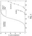
- FIG. 1is a graph showing conversion efficiency (%) as a function of temperature (° C.) for a pyrolytic decomposition method using a nickel-gallium eutectic alloy in accordance with some embodiments of the present disclosure in comparison to reported experimental data for molten tin, non-catalytic and equilibrium processes.
- FIG. 2is a process flow diagram illustrating an exemplary hydrocarbon decomposition method to produce H 2 and solid carbon in accordance with some embodiments of the present disclosure.
- FIG. 3is a graph showing preliminary thermo-gravimetric data for pyrolytic reforming of a methane deed in accordance with some embodiments of the present disclosure.
- FIG. 4is a scanning electron microscopy (SEM) micrograph showing carbon fibers that were produced as a floating slag on the surface of a molten metal in accordance with some embodiments of the present disclosure.
- FIG. 5schematically illustrates a hydrocarbon decomposition system in accordance with some embodiments of the present disclosure.
- the term “comprising”may include the embodiments “consisting of” and “consisting essentially of.”
- the terms “comprise(s),” “include(s),” “having,” “has,” “can,” “contain(s),” and variants thereof, as used herein,are intended to be open-ended transitional phrases that require the presence of the named ingredients or steps and permit the presence of other ingredients or steps.
- compositions, mixtures, or processesas “consisting of” and “consisting essentially of” the enumerated ingredients or steps, which allows the presence of only the named ingredients or steps, along with any impurities that might result therefrom, and excludes other ingredients or steps.
- approximating languagemay be applied to modify any quantitative representation that may vary without resulting in a change in the basic function to which it is related. Accordingly, a value modified by a term or terms, such as “about” and “substantially,” may not be limited to the precise value specified, in some cases.
- the modifier “about”should also be considered as disclosing the range defined by the absolute values of the two endpoints. For example, the expression “from about 2 to about 4” also discloses the range “from 2 to 4.”
- the term “about”may refer to plus or minus 10% of the indicated number. For example, “about 10%” may indicate a range of 9% to 11%, and “about 1” may mean from 0.9-1.1.
- each intervening number there between with the same degree of precisionis explicitly contemplated.
- the numbers 7 and 8are contemplated in addition to 6 and 9, and for the range 6.0-7.0, the number 6.0, 6.1, 6.2, 6.3, 6.4, 6.5, 6.6, 6.7, 6.8, 6.9, and 7.0 are explicitly contemplated.
- the term “minimally soluble”encompasses insolubility and very low levels of solubility.
- the solubilityis less than 20 g/L, including less than 15 g/L, less than 10 g/L, less than 8 g/L, less than 5 g/L, less than 3 g/L, and less than 1 g/L.
- a process for hydrocarbon pyrolysis in a liquid metal alloyincludes catalytically decomposing it into a mixture of hydrogen-rich gas phase and a carbon phase.
- the processmay be a continuous process of a batch process.
- a hydrogen-rich hydrocarbon feedis catalytically decomposed into a mixture of lower chain hydrocarbons.
- the hydrogen generated during decompositionmay be used in situ for the further cracking of carbon-hydrogen bonds.
- This methodmay be used to crack crude oil to produce lower chain hydrocarbons.
- the distribution of reaction productsdepends on the reactor operating conditions. The operating conditions can be varied to obtain a more favorable yield of a particular hydrocarbon phase.
- the alloymay include at least one catalyst element and at least one carrier element.
- the catalyst elementmay be nickel, iron, copper, and/or palladium.
- the carrier elementmay be gallium, tin, and/or bismuth.
- the carrier elementis gallium or tin and the catalyst element is nickel in an amount of from a trace amount to about 20 wt %.
- the carrier elementis gallium and the catalyst element is iron in an amount of from a trace amount to about 15 wt %.
- the carrier elementis gallium and/or tin and the catalyst element is copper in an amount of from a trace amount to about 60 wt %.
- the molten and catalyst elementsmight be the same. Non-limiting examples of such a phase include zinc, nickel, or copper operating at a temperature in excess of their melting point.
- the catalytically active liquid metal alloyincludes active material loading up to 10% (Ni—Ga alloy) and 40% (Cu—Ga alloy).
- active material loadingup to 10% (Ni—Ga alloy) and 40% (Cu—Ga alloy).
- hydrocarbonis sparged into a pyrolytic reactor operating at about 600 to 1000° C., including about 800° C.
- the use of a liquid metaladdresses the problem of coking observed in solid catalysts. Since the solid carbon phase is insoluble in the liquid metal or alloy, it readily separates out and can be removed in the form of a floating slag. The continual removal of the carbon phase ensures extended operations without catalyst deactivation.
- the alloy compositionmay further include a solvent component.
- the catalytic componentmay be highly soluble in the solvent. Selective non-limiting examples of this may be use of bismuth, indium, or tin to form a ternary, quaternary, or multi-element alloy with a melting point less than 800° C.
- Non-limiting examples of solvent componentsinclude the metals indium, bismuth, and tin.
- the alloy compositionmay further include a component for reducing the melting temperature of the alloy and/or forming a eutectic.
- the melting temperaturemay be less than 1,000° C., including less than 900° C., less than 850° C., and less than 800° C.
- the foaming properties of the alloymay be controlled to achieve a high void fraction of the gas phase while ensuring maximal gas-molten metal contact. This may be achieved by controlling the rheological properties such as viscosity and non-Newtonian behavior such as shear thickening. Approaches to achieve this include adjusting the concentration of dissolved phase within the molten metal to achieve an appropriately high viscosity necessary to produce a metal foam.
- the dissolved phasemay be a catalyst phase.
- the bubble diameter and bubble pressuremay be controlled using a porous diffuser and flow controller to achieve an adequate shear rate sufficient to modulate the shear-thickening properties of the molten metal.
- the surface tension of the liquid metalis reduced by doping with a small amount of an oxidant (e.g., oxygen or ozone).
- an oxidante.g., oxygen or ozone.
- the molten metal and system designmay improve hydrocarbon conversion to near-equilibrium values by using catalytically-active eutectic metal alloys.
- This approachaddresses the limitations of current pyrolysis processes: coking of supported catalysts and poor catalytic activity of non-transition molten metals. Carbon's low solubility in most molten metals and lower density enables its removal in the form of a floating slag. Low-melting eutectics of known hydrocarbon decomposition catalysts (Mn, Co, Cu, Zn, Ni, Fe) improve the catalytic activity, and a single-pass conversion of 90% at 800° C. is expected, which approaches the thermodynamic limit for methane pyrolysis.
- 1is a graph showing conversion efficiency (%) as a function of temperature (° C.) for a pyrolytic decomposition method using a nickel-gallium eutectic alloy in accordance with some embodiments of the present disclosure in comparison to reported experimental data for molten tin, non-catalytic and equilibrium processes.
- the specific catalyst areacan be enhanced by reducing the hydrocarbon bubble diameter using two approaches. In some embodiments, this is achieved by using a porous diffuser (e.g., a nanoporous membrane) to constrain bubble size, and/or controlling of interfacial tension by maintaining a dynamic-equilibrium of metal oxide by the application of an applied electric field or by the addition of a small amount of oxidant (e.g., O 2 ) to the incoming feed stream.
- a porous diffusere.g., a nanoporous membrane
- the porous diffusermay be used to produce bubbles with diameter in the range of from about 100 nm to about 10 mm.
- the diffuseris an anodized alumina porous membrane.
- the average bubble sizemay be greater than 100 nm, greater than 1 ⁇ m, greater than 10 ⁇ m, greater than 100 ⁇ m, or greater than 1 mm.
- the porous diffusermay have an average pore size in the range of from about 20 nm to about 1 mm.
- the diffuseris an anodized alumina porous membrane.
- the average pore sizemay be greater than 30 nm, greater than 50 nm, greater than 75 nm, greater than 100 nm, or greater than 200 nm.
- the average pore sizeis less than 8 ⁇ m, including less than 50 nm, less than 100 nm, less than 1 ⁇ m, less than 10 ⁇ m, less than 100 ⁇ m, and less than 1000 ⁇ m.
- the reaction vesselmay be lined with a layer of an oxide ion donor.
- oxide ion donorsinclude yttria, zirconia, ceria, scandia, gadolinia, and mixtures thereof.
- the reactor wallacts as an oxide ion donor, and a small electric field is applied between the reactor wall and the molten metal pool. This causes a small amount of oxide ion present in the liner to migrate into the liquid metal, which is adequate to lower the interfacial tension.
- the linercan be regenerated by reversal of polarity of the applied electric field, in the presence of a small amount of oxide dopant in the feed gas.
- the oxide dopantmay be added either continuously or periodically.
- the technologyrepresents a revolutionary process for efficiently converting hydrocarbons into H 2 gas and solid carbon with pyrolytic reformation. If all H 2 production in the U.S. is supplied by this process (15 MT year ⁇ 1 in 2020), then annual savings of 1 quad of energy and 160 MT CO 2 emissions would be achieved. While accomplishing this level of energy savings and emissions reductions would require historic rates of adoption, the projected cost of $1.02 kg ⁇ 1 H 2 or less make such a scenario plausible. Furthermore, the baseline cost, even assuming zero carbon revenue or tax credits, is much lower than water electrolysis using renewables, and is competitive with traditional steam methane reforming.
- the residual carbon product(45 MT year ⁇ 1 in 2020) may have value either as coke (88 MT year ⁇ 1 produced in US), or may supply the entire global markets for carbon black and graphite (25 and 20 MT year ⁇ 1 respectively), further improving H 2 economics.
- the processmay enable net negative emissions through simultaneous biochar and energy production from agricultural waste.
- FIG. 2A non-limiting example of a system and method 100 for H 2 production is shown in FIG. 2 . While natural gas is the typical feedstock, the process is capable of handling longer chain hydrocarbons as well.
- a hydrocarbon feed 110is continually injected into a reactor 120 (e.g., a molten metal bubble column reactor) where C—H bonds are catalytically cracked.
- the reactor temperaturee.g., 600-1000° C.
- the temperaturecan also be maintained via a temperature control system 130 (e.g., a reactor).
- Hydrogen 170 produced during the reactionexits the top of the reactor 120 and is used to preheat the feed gas 145 at a first heat exchanger 150 .
- Preheated hydrocarbon gas 155is provided to the reactor 120 .
- a separator 180e.g., a pressure-swing adsorption unit
- hydrocarbon(s) 185is separated from the cooled gas 175 , to yield high purity hydrogen 190 (e.g., greater than 99% purity).
- Use of higher hydrocarbonswould allow the process to be operated at temperatures below 600° C., but with a reduced production rate.
- the carbon phasehas poor solubility in the molten metal, and can be separated gravimetrically.
- the continuous removal of the carbon residue 160ensures that the high catalytic activity of the molten metal is sustained for extended durations.
- the carbon residue 160can be concentrated using a carbon removal system and periodically or continuously removed for further processing or sequestration.
- the hot carbon 160can be used to heat the hydrocarbon feed gas 110 at a second heat exchanger 140 .
- the carbon product 165may be highly pure (e.g., greater than 99% pure).
- ECONOMIC MODELINGEconomic modeling was performed to assess the technology disclosed herein in comparison with existing technologies using existing methane-reforming cost models. The economic model assumes 90% hydrocarbon conversion in the process, including annual replacement of the molten metal.
- the specific reactor cost of the dehydrogenation processis analogous to basic oxygen furnace steelmaking, with an assessed capital cost of less than $600 tpa ⁇ 1 H 2 .
- One of the benefits of this processis the low capital cost relative to competing technologies. This is due in part to the higher space velocity achievable in a bubble column reactor and ambient pressure operation, as well as the absence of an expensive CO 2 capture system ($60 ton ⁇ 1 CO 2 ). No CO 2 credits are included in the cost models.
- the baseline hydrogen production costis $1.13 kg ⁇ 1 H 2 , which is competitive with existing technologies such as steam reforming ($1.18 kg ⁇ 1 H 2 ), and is dominated by amortized capital and methane feedstock.
- FIG. 5schematically illustrates a hydrocarbon decomposition system 200 in accordance with some embodiments of the present disclosure.
- the system 200includes a reactor 220 and a carbon settler 295 .
- the reactor 220 and carbon settler 295are fluidly connected via a first conduit 292 and a second conduit 294 . These conduits 292 , 294 allow for liquid metal recirculation.
- the reactor 220contains a catalytic liquid alloy 298 . Hydrocarbons are fed into the alloy 298 via hydrocarbon feed 210 .
- the hydrocarbon gas 212forms bubbles 296 in the catalytic alloy 298 .
- a hydrogen-rich gas streamis recovered via outlet 270 and a carbon product is recovered via outlet 260 .
- the systemincludes a bubble column reactor with a gravity separator to ensure the continuous separation and removal of the carbon phase.
- the reactorcan be optimized (e.g., reactor sizing, liner materials and design of the feed sparger) depending on the desired products.
- the systemfurther includes at least one internal structure upon which gas can attach.
- the structuremay be a high aspect ratio structure.
- the structurecomprises silicon carbide, alumina, or quartz.
- the structuremay be a vertical wire and may ensure elongated bubble shape and higher surface area.
- the aspect ratio of the structuremay be greater than 3:1, including greater than 5:1, greater than 7:1, greater than 10:1, and greater than 20:1.
- the high aspect ratio structurecould be continuously pulled through the molten metal to serve as a bubble guide (vertical wire ensures elongated bubble shape, higher surface area) and a component for harvesting solid carbon.
- the internal structureis a silicon carbide string or wire.
- the carbon removal systemmay include a gravity settler (e.g., for heavy particles) and/or a cyclone separator (e.g., for lighter/entrained particles).
- the typical size of the heavy particlesis determined from the largest carbon particle that would be neutrally buoyant in the gas space velocity.
- the carrier gascan be hydrogen at 800° C. (density 23 g L ⁇ 1 ).
- the drag or lift force exerted by the gas onto the particleis equated to the particle mass for neutrally buoyant masses.
- the typical particle sizeis 50 nm (1 cm s ⁇ 1 ), 5 ⁇ m (10 cm s ⁇ 1 ), and 500 ⁇ m (1 m s ⁇ 1 ).
- the precise particle sizeis determined by the carbon particle shape. In this particular scenario, particles under 1 ⁇ m would be considered lighter particles and those over 100 ⁇ m would be considered heavy particles.
- the interfacial tension of the liquid metalis controlled by doping the feed gas with an oxidant (e.g., O 2 ).
- an oxidante.g., O 2
- the oxidantmay also be selected from one or more metal oxides or mixed metal oxides.
- the alloy composition and operating conditionscan be adjusted for the production of high-value carbon phases such as carbon fibers, graphene, battery-grade graphite, and/or CNTs.
- the carbon phase particleshave an average aspect ratio in the range of from about 1 to about 500, including from about 1 to about 50, from about 2 to about 40, and from about 3 to about 25.
- the hydrocarbon feedcontains one or more hydrocarbons selected from alkanes, alkenes, arenes, and alkynes.
- the number of carbon atoms in the hydrocarbon chainmay range from a single carbon atom (C 1 ) to a 70 carbon arrangement (C 70 ), including C 1 to C 20 .
- the systems and methods of the present disclosureprovide various advantages over the prior art. For example, the systems and methods prevent coking of catalysts and ensure long-term steady operation. Additionally, the systems and methods may ensure near-equilibrium conversion of hydrocarbons. Operation at elevated temperatures is not required. The co-production of a high value carbon phase greatly improves economic efficiency. Additionally, the systems and methods are environmentally friendly with reduced carbon dioxide emissions. Furthermore, the reactor design may ensure high gas hourly space velocities, thereby ensuring a low capital cost.
- the alloyis a eutectic composition having a fixed melting point of (e.g., about ⁇ 30° C.).
- the reactoris a column reactor with hydrocarbon bubbled through a porous (e.g., nanoporous) sparger with O 2 gas mixed in the feed stream to chemically modify the molten metal surface tension.
- the reactorincludes a liner made of an oxygen donor (e.g., ceria and/or yttria-stabilized zirconia).
- an oxygen donore.g., ceria and/or yttria-stabilized zirconia.
- the reactorincludes vertical strings to allow a high bubble density while preventing coalescence, while simultaneously nucleating the formation of carbon particles.
- the aspect ratio of the carbon particlesmay be controlled by the choice of catalyst and the partial pressure of hydrogen in the feed gas.
- the use of copper catalysts or an increased hydrogen partial pressure in the feed gaspromotes the formation of graphitic planar morphologies.
- the use of nickelpromotes the formation of higher aspect ratio carbon fibers.
- the aspect ratio of the carbon fibers thus formedcan be controlled to within a target value by adjusting the relative loading of Ni and Cu, or by optimizing the feed gas pressure.
- the carbon removal systemmay rely on the gravimetric separation between the particulate carbon phase and the molten metal.
- the slurry of carbon particles in molten metalis transported to a separate settling tank and the particle free molten metal is transported back into the reaction vessel.
- the carbon particlesform a slag layer on the molten metal within the reactor. This can be scraped away to ensure continuous removal of heavy carbon.
- the lighter particles carried away in the gas streammay be separated using a cyclone or electrostatic separator.
- the reaction vesselmay be a bubble column reactor with a modest aspect ratio (e.g., having a length:diameter ratio of less than 3).
- the molten metal contained in the reactormay fill no higher than 40% of the volume.
- the reactormay have sufficient head space (e.g., up to 20%) to accommodate ancillary units such as agitators or carbon removal scrapers and feed gas lances as required.
- the inside of the reactormay be lined with an oxide-conducting mixed metal oxide which provides a limited supply of oxygen to modulate the surface tension of the molten metal.
- the oxide layeralso serves the purposed of protecting the reaction vessel from corrosion by the molten metal.
- the thickness of this layermay be from about 50 ⁇ m to about 1 cm, including from about 100 ⁇ m to about 500 ⁇ m.
- the feed gasis sparged into the reactor at a modest partial pressure (e.g., 0.1 to 10 bar), high temperature (e.g., 600 to 1000° C.) and high space velocity that is substantially higher than the state of the art steam reforming process (GHSV greater than 3,000 h ⁇ 1 ).
- Electric fieldsmay be used to enhance the rate of catalytic reactions.
- One such exampleis the methane steam reforming reaction where an electric field (e.g., about 1.25 to about 1.5 eV) is applied to tune the catalyst selectivity.
- the electric fieldis negative in sign and serves the purpose of providing dopant oxygen atoms to reduce the surface tension of the molten metal and enhance its catalytically active surface area.
- the applied fieldis oxidizing in nature.
- a positive electric fieldmay be considered for removal of the oxide species.
- the catalytic hydrocrackingis performed on hydrocarbons from naphtha, liquefied petroleum gas, heavy crude oil or oil sands, wood, and/or dehydrated biomass with a low oxygen content.
- the carbon-hydrogen bondsare cleaved to produce shorter carbon chain species.
- the hydrogen produced as a result of the cracking reactionmay be used for the in-situ saturation of alkenes, alkynes and arenes to alkanes, alkenes and cycloalkanes respectively.
- syngas and bio-oilmay be non-limiting pyrolysis products in addition to carbon and hydrogen.
- One non-limiting potential applicationincludes the use of the pyrolysis of cellulosic biomass such as lignin, which is a component of the waste stream produced by the pulp and paper industry.
- the systems of the present disclosuremay be integrated with a natural gas flare site and chemical processing to produce ammonia.
- the produced hydrogenmay be used at a fueling station for transportation applications, as a reactant for chemical synthesis (ammonia production, crude oil refining), or it may be converted to electricity.
- the solid carboncan be easily separated and sequestered far more easily than gaseous or supercritical CO 2 , or it may be used as a manufacturing material (petroleum coke, synthetic graphite).
- the processis a minimum-emission (less than 0.50 kg CO 2 kg ⁇ 1 H 2 ), low-cost ($1.13 kg ⁇ 1 H 2 ) alternative to conventional hydrogen production processes such as steam reforming ($1.18 kg ⁇ 1 H 2 ), and could be used instead of petroleum cokers for the environmentally-friendly cracking of bituminous oil to produce synthetic crude oil, which is easier to transport.
- DSCDifferential scanning calorimetry
- FIG. 3is a graph showing preliminary thermo-gravimetric data for pyrolytic reforming of a methane feed.
- FIG. 4is a SEM micrograph showing carbon fibers that were produced as a floating slag on the surface of a molten metal.
Landscapes
- Chemical & Material Sciences (AREA)
- Organic Chemistry (AREA)
- Engineering & Computer Science (AREA)
- Materials Engineering (AREA)
- Chemical Kinetics & Catalysis (AREA)
- Metallurgy (AREA)
- Mechanical Engineering (AREA)
- Inorganic Chemistry (AREA)
- Combustion & Propulsion (AREA)
- Oil, Petroleum & Natural Gas (AREA)
- General Chemical & Material Sciences (AREA)
- Physics & Mathematics (AREA)
- Thermal Sciences (AREA)
- General Health & Medical Sciences (AREA)
- Health & Medical Sciences (AREA)
- Textile Engineering (AREA)
- Production Of Liquid Hydrocarbon Mixture For Refining Petroleum (AREA)
- Catalysts (AREA)
Abstract
Description
| Global demand | |||
| (MT year−1) | Reference | ||
| Hydrogen | >50 | https://www.hydrogen.energy.gov/pdfs/hpep_report_2013.pdf |
| Coke | 651 | https://www.statista.com/statistics/267891/global-coke-production-since-1993/ |
| Graphite | 1.2 | http://www.csaglobal.com/wp-content/uploads/2016/03/Paydirt-Media-14-March-2016.pdf |
| Carbon black | >15 (projected) | http://www.ceresana.com/en/market-studies/chemicals/carbon-black/ |
| Carbon fiber | 0.2 (projected) | http://www.grandviewresearch.com/industry-analysis/carbon-fiber-market-analysis |
| CNT | 0.013 | http://www.nanowerk.com/spotlight/spotid=23118.php |
| Coal | |||
| Steam Reforming | Gasification | Present | |
| Technical Metric | (State of the Art) | (Conventional) | Application |
| Production Cost | 1.18 | 2.10 | 1.13 (0.42 if |
| ($ kg−1H2) | C is sold | ||
| Specific Capital | 1,200 | 4,400 | 600 |
| Cost ($ tpa−1H2) | |||
| Specific CO2 | 7.5 | 18 | ≤0.50 |
| emissions (kg | |||
| CO2per kg H2) | |||
| Energy Efficiency | 74 | 60 | 58 |
| (%) | |||
| GHSV (h−1) | 3-30,000 | 2,000 (WGS) | >10,000 |
| Overall Reaction | CH4+ 2H2O −> | C + 2H2O −> | CH4−> C + 2H2 |
| CO2+ 4H2 | CO2+ 2H2 | ||
Claims (11)
Priority Applications (3)
| Application Number | Priority Date | Filing Date | Title |
|---|---|---|---|
| US15/681,522US10851307B2 (en) | 2017-08-21 | 2017-08-21 | System and method for pyrolysis using a liquid metal catalyst |
| EP18185524.8AEP3446780B1 (en) | 2017-08-21 | 2018-07-25 | System and method for pyrolysis using a liquid metal catalyst |
| CA3014935ACA3014935C (en) | 2017-08-21 | 2018-08-17 | System and method for pyrolysis using a liquid metal catalyst |
Applications Claiming Priority (1)
| Application Number | Priority Date | Filing Date | Title |
|---|---|---|---|
| US15/681,522US10851307B2 (en) | 2017-08-21 | 2017-08-21 | System and method for pyrolysis using a liquid metal catalyst |
Publications (2)
| Publication Number | Publication Date |
|---|---|
| US20190055173A1 US20190055173A1 (en) | 2019-02-21 |
| US10851307B2true US10851307B2 (en) | 2020-12-01 |
Family
ID=63047235
Family Applications (1)
| Application Number | Title | Priority Date | Filing Date |
|---|---|---|---|
| US15/681,522ActiveUS10851307B2 (en) | 2017-08-21 | 2017-08-21 | System and method for pyrolysis using a liquid metal catalyst |
Country Status (3)
| Country | Link |
|---|---|
| US (1) | US10851307B2 (en) |
| EP (1) | EP3446780B1 (en) |
| CA (1) | CA3014935C (en) |
Cited By (5)
| Publication number | Priority date | Publication date | Assignee | Title |
|---|---|---|---|---|
| US11577955B2 (en)* | 2018-08-30 | 2023-02-14 | ExxonMobil Technology and Engineering Company | Systems and processes for molten media pyrolysis |
| US11591212B2 (en)* | 2018-08-30 | 2023-02-28 | ExxonMobil Technology and Engineering Company | Systems and processes for molten media pyrolysis |
| RU2798837C1 (en)* | 2022-12-19 | 2023-06-28 | Алексей Леонидович Торопов | Reactor for producing hydrogen and solid carbon from hydrocarbon gases |
| IT202200014503A1 (en) | 2022-07-08 | 2024-01-08 | Nextchem Tech S P A | PROCESS AND APPARATUS FOR THE SEPARATION, REMOVAL AND PURIFICATION OF SOLID CARBON FROM A HYDROGEN PRODUCTION REACTOR BY CRACKING METHANE AND/OR LOW-CO2 EMISSION HYDROCARBONS |
| US12390781B2 (en) | 2022-09-15 | 2025-08-19 | Xerox Corporation | Systems and methods for hydrocarbon pyrolysis |
Families Citing this family (30)
| Publication number | Priority date | Publication date | Assignee | Title |
|---|---|---|---|---|
| US11453584B2 (en)* | 2018-06-29 | 2022-09-27 | Palo Alto Research Center Incorporated | High throughput methane pyrolysis reactor for low-cost hydrogen production |
| CN109999813A (en)* | 2019-03-15 | 2019-07-12 | 上海大学 | A kind of methane catalytic decomposition catalyst for preparing hydrogen and preparation method thereof |
| CN110358940B (en)* | 2019-07-04 | 2021-02-12 | 天津大学 | Preparation method of 3D printing in situ synthesis of three-dimensional graphene-reinforced nickel-based composites |
| CN110343555A (en)* | 2019-08-26 | 2019-10-18 | 河南科技学院 | A kind of liquid alloy catalytic pyrolysis biomass prepares the method and system of high Hydrogen fuel |
| US11680299B2 (en) | 2019-09-04 | 2023-06-20 | Palo Alto Research Center Incorporated | Process and system for steel and hydrogen production using recycled ferrous scrap and natural gas |
| AU2020372186A1 (en)* | 2019-10-21 | 2022-04-21 | Newsouth Innovations Pty Limited | Catalysts or catalytic systems comprising liquid metals and uses thereof |
| CN110885955B (en)* | 2019-10-31 | 2020-12-22 | 成都工业学院 | A kind of copper matrix composite material and preparation method thereof |
| US11987497B2 (en) | 2019-12-06 | 2024-05-21 | Palo Alto Research Center Incorporated | Liquid metal condensate catalyzed hydrocarbon pyrolysis |
| CN111057899B (en)* | 2019-12-23 | 2021-07-20 | 湖南碳材科技有限公司 | Graphene/silicon carbide reinforced copper-based composite material and preparation method thereof |
| CN111056548A (en)* | 2019-12-24 | 2020-04-24 | 中国科学院上海微系统与信息技术研究所 | Co-production method and device of few-layer graphene and hydrogen |
| CN111235421B (en)* | 2020-01-16 | 2021-11-09 | 长安大学 | Method for preparing SiC particle reinforced Cu-based composite material with high volume fraction by non-pressure infiltration |
| CA3171206A1 (en)* | 2020-03-13 | 2021-09-16 | Samuel SHANER | Methods of pneumatic carbon removal |
| CN111302648B (en)* | 2020-03-24 | 2022-11-01 | 上海交通大学医学院附属第九人民医院 | Alloy material and water mist prevention treatment method |
| US20230219814A1 (en)* | 2020-05-19 | 2023-07-13 | The University Of British Columbia | Hydrogen production from hydrocarbons without carbon dioxide emissions |
| CN111807346B (en)* | 2020-07-20 | 2023-03-14 | 山东理工大学 | Preparation method of broadband efficient wave-absorbing macroporous thin-layer carbon material |
| CN114135367B (en)* | 2020-09-03 | 2023-03-28 | 长城汽车股份有限公司 | Methane conversion gas generation device and automobile |
| US11560645B2 (en)* | 2020-09-25 | 2023-01-24 | Palo Alto Research Center Incorporated | Carbon fiber fabrication systems and methods |
| CN112582629B (en)* | 2020-12-09 | 2022-02-15 | 江南大学 | Ultrathin carbon nanosheet loaded nano high-entropy alloy electrocatalyst and preparation method thereof |
| CN112705208A (en)* | 2021-01-29 | 2021-04-27 | 福州大学 | Nickel-gallium alloy catalyst and preparation method and application thereof |
| GB2605797A (en)* | 2021-04-13 | 2022-10-19 | Hiiroc X Developments Ltd | Liquid metal reactor and reaction method |
| CN112938895A (en)* | 2021-04-22 | 2021-06-11 | 成都启川新能源科技有限公司 | System and method for producing hydrogen by cracking natural gas through liquid metal |
| CN113233447A (en)* | 2021-06-07 | 2021-08-10 | 湖北犇星新材料股份有限公司 | Method for continuously synthesizing doped graphene |
| WO2023279034A1 (en)* | 2021-06-29 | 2023-01-05 | Do Robert T | Methods, processes and systems for the production of hydrogen & carbon from waste, biogenic waste and biomass |
| JP2025500009A (en)* | 2021-11-10 | 2025-01-07 | ロイヤル・メルボルン・インスティテュート・オブ・テクノロジー | Method for reducing gaseous carbon oxide |
| WO2023168533A1 (en)* | 2022-03-11 | 2023-09-14 | Acceleware Ltd. | System and method for pyrolysis using an electromagnetic reactor |
| AU2022445160A1 (en)* | 2022-03-11 | 2024-09-26 | Montanuniversität Leoben | Processing a hydrocarbon using pyrolysis, method and apparatus. |
| CN114832729B (en)* | 2022-03-29 | 2023-05-09 | 清华大学 | Device and method for simultaneous production of carbon nanotubes and graphene |
| CN115404346B (en)* | 2022-09-20 | 2023-06-02 | 安徽工程大学 | A kind of copper gallium alloy and its synthesis method and application |
| CN115611236A (en)* | 2022-11-17 | 2023-01-17 | 罗托布斯特(上海)氢能科技有限公司 | Catalytic pyrolysis offshore facility and ship short-flow hydrogen production method, system and system implementation method |
| CN120268408B (en)* | 2025-06-11 | 2025-08-22 | 西南石油大学 | Melting catalyst for preparing carbon material from sludge pyrolysis gas and preparation method and application thereof |
Citations (27)
| Publication number | Priority date | Publication date | Assignee | Title |
|---|---|---|---|---|
| US1107926A (en) | 1913-03-14 | 1914-08-18 | Albert Rudolph Frank | Process of producing hydrogen. |
| US1418385A (en) | 1920-07-17 | 1922-06-06 | Julian M Gerard | Method of manufacturing carbon black, lampblack, and hydrogen |
| US1756877A (en) | 1915-05-03 | 1930-04-29 | Jr Auguste Jean Paris | Process of producing lampblack |
| US1803221A (en)* | 1929-01-25 | 1931-04-28 | Ici Ltd | Production of hydrogen |
| US2760847A (en) | 1951-11-13 | 1956-08-28 | Houdry Process Corp | Production of hydrogen and carbon |
| US2882216A (en) | 1956-05-28 | 1959-04-14 | Exxon Research Engineering Co | Circulatory process for treatment of hydrocarbons with in situ production of hydrogen |
| US3156734A (en) | 1961-05-22 | 1964-11-10 | Happel John | Pyrolysis of methane-hydrogen mixtures |
| US3625026A (en)* | 1969-04-17 | 1971-12-07 | Pilkington Brothers Ltd | Removing dissolved oxygen from molten tin in a glass ribbon float bath |
| US3965252A (en) | 1973-01-20 | 1976-06-22 | Ashland Oil, Inc. | Hydrogen production |
| US4983278A (en) | 1987-11-03 | 1991-01-08 | Western Research Institute & Ilr Services Inc. | Pyrolysis methods with product oil recycling |
| US5537940A (en)* | 1993-06-08 | 1996-07-23 | Molten Metal Technology, Inc. | Method for treating organic waste |
| WO1998022385A1 (en) | 1996-11-22 | 1998-05-28 | Ashland Inc. | Molten metal reactor and process |
| US6110239A (en) | 1996-05-31 | 2000-08-29 | Marathon Ashland Petroleum Llc | Molten metal hydrocarbon gasification process |
| US6350289B1 (en) | 1995-04-13 | 2002-02-26 | Marathon Ashland Petroleum Llc | Two-zone molten metal hydrogen-rich and carbon monoxide-rich gas generation process |
| US20030072705A1 (en) | 2001-03-06 | 2003-04-17 | Kindig James Kelly | Method for the production of hydrogen and applications thereof |
| WO2003045841A1 (en) | 2001-11-29 | 2003-06-05 | Wisconsin Alumni Research Foundation | Low-temperature hydrogen production from oxygenated hydrocarbons |
| US20030130360A1 (en) | 2001-03-06 | 2003-07-10 | Kindig James Kelly | Method for the production of hydrogen-containing gaseous mixtures |
| US6653005B1 (en) | 2000-05-10 | 2003-11-25 | University Of Central Florida | Portable hydrogen generator-fuel cell apparatus |
| US6670058B2 (en) | 2000-04-05 | 2003-12-30 | University Of Central Florida | Thermocatalytic process for CO2-free production of hydrogen and carbon from hydrocarbons |
| US6682714B2 (en) | 2001-03-06 | 2004-01-27 | Alchemix Corporation | Method for the production of hydrogen gas |
| US6719047B2 (en) | 2000-04-24 | 2004-04-13 | Shell Oil Company | In situ thermal processing of a hydrocarbon containing formation in a hydrogen-rich environment |
| EP1462170A1 (en) | 2003-03-28 | 2004-09-29 | European Community | Gas-phase chemical reactions using a molten metal catalyst |
| US7052661B1 (en)* | 2002-01-31 | 2006-05-30 | Envi Res Llc | Method for abatement of mercury emissions from combustion gases |
| US7588746B1 (en) | 2006-05-10 | 2009-09-15 | University Of Central Florida Research Foundation, Inc. | Process and apparatus for hydrogen and carbon production via carbon aerosol-catalyzed dissociation of hydrocarbons |
| US20110089377A1 (en)* | 2009-10-19 | 2011-04-21 | Battelle Energy Alliance, Llc | Molten metal reactor and method of forming hydrogen, carbon monoxide and carbon dioxide using the molten alkaline metal reactor |
| US20110088320A1 (en)* | 2007-04-24 | 2011-04-21 | Dietenberger Mark A | Method and apparatus to produce synthesis gas via flash pyrolysis and gasification in a molten liquid |
| US8034321B2 (en) | 2005-02-10 | 2011-10-11 | Electrovac Ag | Hydrogen production |
- 2017
- 2017-08-21USUS15/681,522patent/US10851307B2/enactiveActive
- 2018
- 2018-07-25EPEP18185524.8Apatent/EP3446780B1/enactiveActive
- 2018-08-17CACA3014935Apatent/CA3014935C/enactiveActive
Patent Citations (29)
| Publication number | Priority date | Publication date | Assignee | Title |
|---|---|---|---|---|
| US1107926A (en) | 1913-03-14 | 1914-08-18 | Albert Rudolph Frank | Process of producing hydrogen. |
| US1756877A (en) | 1915-05-03 | 1930-04-29 | Jr Auguste Jean Paris | Process of producing lampblack |
| US1418385A (en) | 1920-07-17 | 1922-06-06 | Julian M Gerard | Method of manufacturing carbon black, lampblack, and hydrogen |
| US1803221A (en)* | 1929-01-25 | 1931-04-28 | Ici Ltd | Production of hydrogen |
| US2760847A (en) | 1951-11-13 | 1956-08-28 | Houdry Process Corp | Production of hydrogen and carbon |
| US2882216A (en) | 1956-05-28 | 1959-04-14 | Exxon Research Engineering Co | Circulatory process for treatment of hydrocarbons with in situ production of hydrogen |
| US3156734A (en) | 1961-05-22 | 1964-11-10 | Happel John | Pyrolysis of methane-hydrogen mixtures |
| US3625026A (en)* | 1969-04-17 | 1971-12-07 | Pilkington Brothers Ltd | Removing dissolved oxygen from molten tin in a glass ribbon float bath |
| US3965252A (en) | 1973-01-20 | 1976-06-22 | Ashland Oil, Inc. | Hydrogen production |
| US4983278A (en) | 1987-11-03 | 1991-01-08 | Western Research Institute & Ilr Services Inc. | Pyrolysis methods with product oil recycling |
| US5537940A (en)* | 1993-06-08 | 1996-07-23 | Molten Metal Technology, Inc. | Method for treating organic waste |
| US6350289B1 (en) | 1995-04-13 | 2002-02-26 | Marathon Ashland Petroleum Llc | Two-zone molten metal hydrogen-rich and carbon monoxide-rich gas generation process |
| US6110239A (en) | 1996-05-31 | 2000-08-29 | Marathon Ashland Petroleum Llc | Molten metal hydrocarbon gasification process |
| WO1998022385A1 (en) | 1996-11-22 | 1998-05-28 | Ashland Inc. | Molten metal reactor and process |
| US6670058B2 (en) | 2000-04-05 | 2003-12-30 | University Of Central Florida | Thermocatalytic process for CO2-free production of hydrogen and carbon from hydrocarbons |
| US6719047B2 (en) | 2000-04-24 | 2004-04-13 | Shell Oil Company | In situ thermal processing of a hydrocarbon containing formation in a hydrogen-rich environment |
| US6653005B1 (en) | 2000-05-10 | 2003-11-25 | University Of Central Florida | Portable hydrogen generator-fuel cell apparatus |
| US20030072705A1 (en) | 2001-03-06 | 2003-04-17 | Kindig James Kelly | Method for the production of hydrogen and applications thereof |
| US6663681B2 (en) | 2001-03-06 | 2003-12-16 | Alchemix Corporation | Method for the production of hydrogen and applications thereof |
| US20030130360A1 (en) | 2001-03-06 | 2003-07-10 | Kindig James Kelly | Method for the production of hydrogen-containing gaseous mixtures |
| US6682714B2 (en) | 2001-03-06 | 2004-01-27 | Alchemix Corporation | Method for the production of hydrogen gas |
| US6685754B2 (en) | 2001-03-06 | 2004-02-03 | Alchemix Corporation | Method for the production of hydrogen-containing gaseous mixtures |
| WO2003045841A1 (en) | 2001-11-29 | 2003-06-05 | Wisconsin Alumni Research Foundation | Low-temperature hydrogen production from oxygenated hydrocarbons |
| US7052661B1 (en)* | 2002-01-31 | 2006-05-30 | Envi Res Llc | Method for abatement of mercury emissions from combustion gases |
| EP1462170A1 (en) | 2003-03-28 | 2004-09-29 | European Community | Gas-phase chemical reactions using a molten metal catalyst |
| US8034321B2 (en) | 2005-02-10 | 2011-10-11 | Electrovac Ag | Hydrogen production |
| US7588746B1 (en) | 2006-05-10 | 2009-09-15 | University Of Central Florida Research Foundation, Inc. | Process and apparatus for hydrogen and carbon production via carbon aerosol-catalyzed dissociation of hydrocarbons |
| US20110088320A1 (en)* | 2007-04-24 | 2011-04-21 | Dietenberger Mark A | Method and apparatus to produce synthesis gas via flash pyrolysis and gasification in a molten liquid |
| US20110089377A1 (en)* | 2009-10-19 | 2011-04-21 | Battelle Energy Alliance, Llc | Molten metal reactor and method of forming hydrogen, carbon monoxide and carbon dioxide using the molten alkaline metal reactor |
Non-Patent Citations (14)
| Title |
|---|
| A. Abanades et al, "Thermal cracking of methane into Hydrogen for a CO2-free utilization of natural gas", International Journal of Hydrogen Energy 38, 2013, pp. 8491-8496. |
| A. Abanades et al., "Technological challenges for industrial development of hydrogen production based on methane cracking", Energy 46, 2012, pp. 359-363. |
| Alberto Abanades et al, "Development of methane decarbonisation based on liquid metal technology for CO2-free production of hydrogen", International Journal of Hydrogen Energy 41, 2016, pp. 8159-8167. |
| Alejandro A. Munera Parra et al., "Molten metal capillary reactor for the high-temperature pyrolysis of methane", International Journal of Hydrogen Energy 42, 2017, pp. 13641-13648. |
| Brett Parkinson et al, "Techno-Economic Analysis of Methane Pyrolysis in Molten Metals: Decarbonizing Natural Gas", Chem. Eng. Technol., 2017, 40, No. 6, pp. 1022-1030. |
| D. Paxman et al., "Initial experimental and theoretical investigation of solar molten media methane cracking for hydrogen production," Energy Procedia 49, 2014, pp. 2027-2036. |
| European Patent Office, European Search Report in related application No. 18185524.8 (dated Jan. 15, 2019). |
| James E. Funk, "Thermochemical hydrogen production: past and present", International Journal of Hydrogen Energy 26, 2001 pp. 185-190. |
| M. Plevan et al, "Thermal cracking of methane in a liquid metal bubble column reactor: Experiments and kinetic analysis", International Journal of Hydrogen Energy 40, 2015, pp. 8020-8033. |
| M. Steinberg, "Fossil fuel decarbonization technology for mitigating global warming", International Journal of Hydrogen Energy 13, 1999, pp. 771-777. |
| R. M. Navarro et al, "Hydrogen Production Reactions from Carbon Feedstocks: Fossil Fuels and Biomass", Chem. Rev., 2007, 107, pp. 3952-3991. |
| Sageman, "Surface tension of molten metal using the sessile drop method", Retrospective Theses and Dissertations, Iowa State University, 1972, pp. 1-107. (Year: 1972).* |
| Sylvain Rodat et al, "Experimental Evaluation of Indirect Heating Tubular Reactors for Solar Methane Pyrolysis", International Journal of Chemical Reactor Engineering, vol. 8, 2010, Article A25, 22 pages. |
| Sylvain Rodat et al, "Kinetic modelling of methane decomposition in a tubular solar reactor", Chemical Engineering Journal 146, 2009, pp. 120-127. |
Cited By (5)
| Publication number | Priority date | Publication date | Assignee | Title |
|---|---|---|---|---|
| US11577955B2 (en)* | 2018-08-30 | 2023-02-14 | ExxonMobil Technology and Engineering Company | Systems and processes for molten media pyrolysis |
| US11591212B2 (en)* | 2018-08-30 | 2023-02-28 | ExxonMobil Technology and Engineering Company | Systems and processes for molten media pyrolysis |
| IT202200014503A1 (en) | 2022-07-08 | 2024-01-08 | Nextchem Tech S P A | PROCESS AND APPARATUS FOR THE SEPARATION, REMOVAL AND PURIFICATION OF SOLID CARBON FROM A HYDROGEN PRODUCTION REACTOR BY CRACKING METHANE AND/OR LOW-CO2 EMISSION HYDROCARBONS |
| US12390781B2 (en) | 2022-09-15 | 2025-08-19 | Xerox Corporation | Systems and methods for hydrocarbon pyrolysis |
| RU2798837C1 (en)* | 2022-12-19 | 2023-06-28 | Алексей Леонидович Торопов | Reactor for producing hydrogen and solid carbon from hydrocarbon gases |
Also Published As
| Publication number | Publication date |
|---|---|
| US20190055173A1 (en) | 2019-02-21 |
| EP3446780A1 (en) | 2019-02-27 |
| CA3014935C (en) | 2022-05-31 |
| CA3014935A1 (en) | 2019-02-21 |
| EP3446780B1 (en) | 2021-02-24 |
Similar Documents
| Publication | Publication Date | Title |
|---|---|---|
| US10851307B2 (en) | System and method for pyrolysis using a liquid metal catalyst | |
| CN103146413B (en) | The method in the presence of coming from the hydrogen of non-fossil sources, carbon-based material being converted by the hydridization approach that direct liquefaction and indirect liquefaction combine | |
| US8816137B2 (en) | Efficient and environmentally friendly processing of heavy oils to methanol and derived products | |
| Jafarian et al. | Steam reforming of bagasse to hydrogen and synthesis gas using ruthenium promoted NiFe/γAl2O3nano-catalysts | |
| CN109135798B (en) | Enhanced fischer-tropsch process for producing hydrocarbon fuels in a GTL environment | |
| WO2021185869A1 (en) | Production of hydrocarbons | |
| JP2014515779A5 (en) | ||
| JP5801417B2 (en) | Fischer-Tropsch process enhancement for hydrocarbon fuel preparation | |
| US7001928B2 (en) | Slurry activation of Fischer-Tropsch catalyst with carbon monoxide co-feed | |
| JP2014515779A (en) | How to improve the quality of heavy oil and bitumen | |
| US20150175417A1 (en) | Method for modifying carbon dioxide using carbon black catalyst | |
| JP2018083954A (en) | Improvement of fischer-tropsch process for hydrocarbon fuel formulation in a gtl environment | |
| US20130090393A1 (en) | Process for producing hydrocarbons from syngas | |
| JP5301574B2 (en) | Method for refining FT synthetic oil and mixed crude oil | |
| US9074148B2 (en) | Hydrogen and carbon utilization in synthetic fuels production plants | |
| CA2872194C (en) | Process for co-producing commercially valuable products from byproducts of fischer-tropsch process for hydrocarbon fuel formulation in a gtl environment | |
| CN101220288A (en) | Liquefaction method for integrating moulded coal | |
| EP1920836A1 (en) | Process for regenerating a cobalt catalyst | |
| Rytter et al. | Biomass‐to‐Liquids by the Fischer–Tropsch Process | |
| CN111566042B (en) | Precious metal catalysts and methods for reforming methane and other hydrocarbons | |
| CN102031170A (en) | Novel method for preparing urban gas from coal mine gas | |
| Alhassan et al. | Emerging trends in hydrogen and synfuel generation: a state-of-the-art review | |
| WO2014112510A1 (en) | Hydrocarbon synthesis reaction apparatus | |
| Wahyudi et al. | Tailoring catalyst support with bicontinuous concentric lamellar morphology for dry reforming of methane | |
| Homs et al. | Biohydrogen and biomethane production |
Legal Events
| Date | Code | Title | Description |
|---|---|---|---|
| AS | Assignment | Owner name:PALO ALTO RESEARCH CENTER INCORPORATED, CALIFORNIA Free format text:ASSIGNMENT OF ASSIGNORS INTEREST;ASSIGNORS:DESAI, DIVYARAJ;RIVEST, JESSICA LOUIS BAKER;REEL/FRAME:043341/0738 Effective date:20170817 | |
| STPP | Information on status: patent application and granting procedure in general | Free format text:RESPONSE TO NON-FINAL OFFICE ACTION ENTERED AND FORWARDED TO EXAMINER | |
| STPP | Information on status: patent application and granting procedure in general | Free format text:FINAL REJECTION MAILED | |
| STPP | Information on status: patent application and granting procedure in general | Free format text:DOCKETED NEW CASE - READY FOR EXAMINATION | |
| STPP | Information on status: patent application and granting procedure in general | Free format text:NON FINAL ACTION MAILED | |
| STPP | Information on status: patent application and granting procedure in general | Free format text:RESPONSE TO NON-FINAL OFFICE ACTION ENTERED AND FORWARDED TO EXAMINER | |
| STPP | Information on status: patent application and granting procedure in general | Free format text:FINAL REJECTION MAILED | |
| STPP | Information on status: patent application and granting procedure in general | Free format text:RESPONSE AFTER FINAL ACTION FORWARDED TO EXAMINER | |
| STPP | Information on status: patent application and granting procedure in general | Free format text:ADVISORY ACTION MAILED | |
| STPP | Information on status: patent application and granting procedure in general | Free format text:PUBLICATIONS -- ISSUE FEE PAYMENT RECEIVED | |
| STCF | Information on status: patent grant | Free format text:PATENTED CASE | |
| AS | Assignment | Owner name:XEROX CORPORATION, CONNECTICUT Free format text:ASSIGNMENT OF ASSIGNORS INTEREST;ASSIGNOR:PALO ALTO RESEARCH CENTER INCORPORATED;REEL/FRAME:064038/0001 Effective date:20230416 | |
| AS | Assignment | Owner name:CITIBANK, N.A., AS COLLATERAL AGENT, NEW YORK Free format text:SECURITY INTEREST;ASSIGNOR:XEROX CORPORATION;REEL/FRAME:064760/0389 Effective date:20230621 | |
| AS | Assignment | Owner name:XEROX CORPORATION, CONNECTICUT Free format text:CORRECTIVE ASSIGNMENT TO CORRECT THE REMOVAL OF US PATENTS 9356603, 10026651, 10626048 AND INCLUSION OF US PATENT 7167871 PREVIOUSLY RECORDED ON REEL 064038 FRAME 0001. ASSIGNOR(S) HEREBY CONFIRMS THE ASSIGNMENT;ASSIGNOR:PALO ALTO RESEARCH CENTER INCORPORATED;REEL/FRAME:064161/0001 Effective date:20230416 | |
| AS | Assignment | Owner name:JEFFERIES FINANCE LLC, AS COLLATERAL AGENT, NEW YORK Free format text:SECURITY INTEREST;ASSIGNOR:XEROX CORPORATION;REEL/FRAME:065628/0019 Effective date:20231117 | |
| AS | Assignment | Owner name:XEROX CORPORATION, CONNECTICUT Free format text:TERMINATION AND RELEASE OF SECURITY INTEREST IN PATENTS RECORDED AT RF 064760/0389;ASSIGNOR:CITIBANK, N.A., AS COLLATERAL AGENT;REEL/FRAME:068261/0001 Effective date:20240206 Owner name:CITIBANK, N.A., AS COLLATERAL AGENT, NEW YORK Free format text:SECURITY INTEREST;ASSIGNOR:XEROX CORPORATION;REEL/FRAME:066741/0001 Effective date:20240206 | |
| MAFP | Maintenance fee payment | Free format text:PAYMENT OF MAINTENANCE FEE, 4TH YEAR, LARGE ENTITY (ORIGINAL EVENT CODE: M1551); ENTITY STATUS OF PATENT OWNER: LARGE ENTITY Year of fee payment:4 | |
| AS | Assignment | Owner name:U.S. BANK TRUST COMPANY, NATIONAL ASSOCIATION, AS COLLATERAL AGENT, CONNECTICUT Free format text:FIRST LIEN NOTES PATENT SECURITY AGREEMENT;ASSIGNOR:XEROX CORPORATION;REEL/FRAME:070824/0001 Effective date:20250411 | |
| AS | Assignment | Owner name:U.S. BANK TRUST COMPANY, NATIONAL ASSOCIATION, AS COLLATERAL AGENT, CONNECTICUT Free format text:SECOND LIEN NOTES PATENT SECURITY AGREEMENT;ASSIGNOR:XEROX CORPORATION;REEL/FRAME:071785/0550 Effective date:20250701 |