US10850869B2 - Spacecraft servicing devices and related assemblies, systems, and methods - Google Patents
Spacecraft servicing devices and related assemblies, systems, and methodsDownload PDFInfo
- Publication number
- US10850869B2 US10850869B2US16/041,709US201816041709AUS10850869B2US 10850869 B2US10850869 B2US 10850869B2US 201816041709 AUS201816041709 AUS 201816041709AUS 10850869 B2US10850869 B2US 10850869B2
- Authority
- US
- United States
- Prior art keywords
- spacecraft
- servicing
- target
- pod
- orbit
- Prior art date
- Legal status (The legal status is an assumption and is not a legal conclusion. Google has not performed a legal analysis and makes no representation as to the accuracy of the status listed.)
- Active, expires
Links
Images


Classifications
- B—PERFORMING OPERATIONS; TRANSPORTING
- B64—AIRCRAFT; AVIATION; COSMONAUTICS
- B64G—COSMONAUTICS; VEHICLES OR EQUIPMENT THEREFOR
- B64G1/00—Cosmonautic vehicles
- B64G1/10—Artificial satellites; Systems of such satellites; Interplanetary vehicles
- B64G1/1078—Maintenance satellites
- B64G1/007—
- B—PERFORMING OPERATIONS; TRANSPORTING
- B64—AIRCRAFT; AVIATION; COSMONAUTICS
- B64G—COSMONAUTICS; VEHICLES OR EQUIPMENT THEREFOR
- B64G1/00—Cosmonautic vehicles
- B64G1/22—Parts of, or equipment specially adapted for fitting in or to, cosmonautic vehicles
- B64G1/24—Guiding or controlling apparatus, e.g. for attitude control
- B64G1/242—Orbits and trajectories
- B64G1/2427—Transfer orbits
- B—PERFORMING OPERATIONS; TRANSPORTING
- B64—AIRCRAFT; AVIATION; COSMONAUTICS
- B64G—COSMONAUTICS; VEHICLES OR EQUIPMENT THEREFOR
- B64G1/00—Cosmonautic vehicles
- B64G1/22—Parts of, or equipment specially adapted for fitting in or to, cosmonautic vehicles
- B64G1/24—Guiding or controlling apparatus, e.g. for attitude control
- B64G1/26—Guiding or controlling apparatus, e.g. for attitude control using jets
- B64G1/262—Guiding or controlling apparatus, e.g. for attitude control using jets having adjustable angles, e.g. gimbaled thrusters
- B64G1/264—Guiding or controlling apparatus, e.g. for attitude control using jets having adjustable angles, e.g. gimbaled thrusters mounted on adjustable booms or the like
- B—PERFORMING OPERATIONS; TRANSPORTING
- B64—AIRCRAFT; AVIATION; COSMONAUTICS
- B64G—COSMONAUTICS; VEHICLES OR EQUIPMENT THEREFOR
- B64G1/00—Cosmonautic vehicles
- B64G1/22—Parts of, or equipment specially adapted for fitting in or to, cosmonautic vehicles
- B64G1/40—Arrangements or adaptations of propulsion systems
- B64G1/402—Propellant tanks; Feeding propellants
- B64G1/4024—Propellant tanks; Feeding propellants refuelling in space
- B—PERFORMING OPERATIONS; TRANSPORTING
- B64—AIRCRAFT; AVIATION; COSMONAUTICS
- B64G—COSMONAUTICS; VEHICLES OR EQUIPMENT THEREFOR
- B64G1/00—Cosmonautic vehicles
- B64G1/22—Parts of, or equipment specially adapted for fitting in or to, cosmonautic vehicles
- B64G1/64—Systems for coupling or separating cosmonautic vehicles or parts thereof, e.g. docking arrangements
- B64G1/641—Interstage or payload connectors
- B64G1/643—Interstage or payload connectors for arranging multiple satellites in a single launcher
- B—PERFORMING OPERATIONS; TRANSPORTING
- B64—AIRCRAFT; AVIATION; COSMONAUTICS
- B64G—COSMONAUTICS; VEHICLES OR EQUIPMENT THEREFOR
- B64G1/00—Cosmonautic vehicles
- B64G1/22—Parts of, or equipment specially adapted for fitting in or to, cosmonautic vehicles
- B64G1/64—Systems for coupling or separating cosmonautic vehicles or parts thereof, e.g. docking arrangements
- B64G1/646—Docking or rendezvous systems
- B64G1/6462—Docking or rendezvous systems characterised by the means for engaging other vehicles
- B64G1/6464—Docking probes and receivers
- B—PERFORMING OPERATIONS; TRANSPORTING
- B64—AIRCRAFT; AVIATION; COSMONAUTICS
- B64G—COSMONAUTICS; VEHICLES OR EQUIPMENT THEREFOR
- B64G1/00—Cosmonautic vehicles
- B64G1/22—Parts of, or equipment specially adapted for fitting in or to, cosmonautic vehicles
- B64G1/64—Systems for coupling or separating cosmonautic vehicles or parts thereof, e.g. docking arrangements
- B64G1/648—Tethers
- B—PERFORMING OPERATIONS; TRANSPORTING
- B64—AIRCRAFT; AVIATION; COSMONAUTICS
- B64G—COSMONAUTICS; VEHICLES OR EQUIPMENT THEREFOR
- B64G1/00—Cosmonautic vehicles
- B64G1/22—Parts of, or equipment specially adapted for fitting in or to, cosmonautic vehicles
- B64G1/24—Guiding or controlling apparatus, e.g. for attitude control
- B64G1/242—Orbits and trajectories
- B64G1/2429—Station keeping
Definitions
- Embodiments of the present disclosuregenerally relate to servicing devices for spacecraft (e.g., satellites).
- embodiments of the present disclosurerelate to servicing devices including one or more detachable servicing devices (e.g., pods or modules) and related devices, systems, assemblies, and methods.
- detachable servicing devicese.g., pods or modules
- spacecraftorbit the Earth for performing various functions including, for example, telecommunication, GPS navigation, weather forecasting, and mapping.
- spacecraftperiodically require servicing to extend their functioning life span.
- Servicingmay include, for example, component repair, refueling, orbit raising, station-keeping, momentum balancing, or other maintenance.
- a servicing spacecraftmay be sent into orbit to dock with a client spacecraft requiring maintenance, and subsequent to docking, perform life extending maintenance on the client spacecraft. Without life extension maintenance, these spacecraft may fall out of service, and replacement is generally extraordinarily expensive and can have a lead time of years.
- Embodiments of the present disclosureinclude a spacecraft servicing device including a body configured to be deployed from a host spacecraft at a location adjacent a target spacecraft, where the host spacecraft houses a plurality of spacecraft servicing devices, and at least one spacecraft servicing component configured to perform at least one servicing operation on the target spacecraft while being coupled to the target spacecraft.
- the at least one spacecraft servicing componentcomprises a thruster assembly configured to alter at least one of an orbit, a velocity, or a momentum of the target spacecraft.
- the thruster assemblycomprises at least one thruster.
- the spacecraft servicing devicefurther includes a communication device configured to receive data relating to the at least one of an orbit, a velocity, or a momentum of the target spacecraft from a location remote from the spacecraft servicing device.
- Embodiments of the present disclosurefurther include a spacecraft servicing pod having a body configured to be deployed from a host spacecraft, a thruster assembly coupled to the body, the thruster assembly configured to alter at least one of an orbit, a velocity, or a momentum of the target spacecraft after being coupled to the target spacecraft, and a communication device configured to receive data relating to the at least one of an orbit, a velocity, or a momentum of the target spacecraft from a location remote from the spacecraft servicing device.
- Embodiments of the present disclosurefurther include a spacecraft servicing pod having a body configured to be deployed from a host spacecraft housing a plurality of spacecraft servicing pods at a location adjacent a target spacecraft, a coupling mechanism coupled to the body and configured to couple the pod to the target spacecraft at the location adjacent the target spacecraft, and at least one spacecraft servicing component configured to perform at least one servicing operation on the target spacecraft.
- the coupling mechanismcomprises at least one movable coupling configured to rotate the body relative to the target spacecraft when the spacecraft servicing pod is coupled to the target spacecraft.
- Embodiments of the present disclosurefurther include a spacecraft servicing system comprising a body configured to be deployed from a host spacecraft, a coupling mechanism attached to the body and configured to couple the pod to a target spacecraft, and a thruster assembly positioned on a single boom arm extending away from the body configured to alter at least one of an orbit, a velocity, or a momentum of the target spacecraft.
- Embodiments of the present disclosurefurther include a spacecraft servicing device including a body configured to be deployed from a host spacecraft at a location adjacent a target spacecraft, where the host spacecraft houses a plurality of spacecraft servicing devices, and a thruster assembly coupled to the body.
- the thruster assemblyis configured to alter at least one of an orbit, a velocity, or a momentum of the target spacecraft when coupled to the target spacecraft.
- Embodiments of the present disclosurefurther include a spacecraft servicing pod having a body configured to be deployed from a host spacecraft housing a plurality of spacecraft servicing pods at a location adjacent a target spacecraft, a coupling mechanism coupled to the body and configured to couple the pod to the target spacecraft at the location adjacent the target spacecraft, and at least one spacecraft servicing component configured to perform at least one servicing operation on the target spacecraft.
- a total mass of the spacecraft servicing podis less than 500 kg.
- Embodiments of the present disclosurefurther include a method of servicing a spacecraft.
- the methodincludes transferring a pod of a spacecraft servicing device to the spacecraft with the spacecraft servicing device, coupling the pod to the spacecraft while the pod is in contact with the spacecraft servicing device, after being coupled to the spacecraft, altering at least one of an orbit or a velocity of the spacecraft with a thruster assembly of the spacecraft servicing device, and receiving data relating to the at least one of an orbit, a velocity, or a momentum of the spacecraft from a location remote from the pod with a communications device.
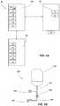
- FIG. 1Ais a simplified schematic view of a spacecraft servicing system and a target spacecraft to be serviced according to one or more embodiments of the present disclosure.
- FIG. 1Bdepicts an embodiment of a fuel tank supply device that may be implemented on one or more devices of the spacecraft servicing system of FIG. 1A .
- FIG. 2Ais a simplified schematic view of a spacecraft servicing device according to one or more embodiments of the present disclosure.
- FIG. 2Bis a simplified schematic view of a spacecraft servicing device according to one or more embodiments of the present disclosure.
- FIGS. 2C through 2Kdepict various embodiments of coupling mechanisms according to one or more embodiments of the present disclosure.
- FIG. 2Lis a perspective view of a spacecraft servicing device according to one or more embodiments of the present disclosure.
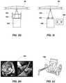
- FIG. 3is a simplified schematic view of a mission extension pod according to one or more embodiments of the present disclosure.
- FIG. 4is a simplified schematic view of a mission extension pod attached to a spacecraft in two thrust vector orientations according to one or more embodiments of the present disclosure.
- FIG. 5is another simplified schematic view of a mission extension pod attached to a spacecraft in two thrust vector orientations according to one or more embodiments of the present disclosure.
- FIG. 6is a simplified schematic view of a resupply device of a spacecraft servicing system according to one or more embodiments of the present disclosure.
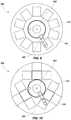
- FIGS. 7 through 10depict various embodiments of spacecraft servicing devices including a number of pods coupled to the spacecraft servicing devices according to one or more embodiments of the present disclosure.
- the term “substantially” in reference to a given parametermeans and includes to a degree that one skilled in the art would understand that the given parameter, property, or condition is met with a small degree of variance, such as within acceptable manufacturing tolerances.
- a parameter that is substantially metmay be at least about 90% met, at least about 95% met, or even at least about 99% met.
- Embodiments of the disclosurerelate generally to spacecraft (e.g., satellite or other vehicle) servicing devices for providing life extending service to spacecraft (otherwise referred to as “clients”).
- the spacecraft servicing systems, assemblies, or devicesmay include one or more deployable spacecraft servicing devices, pods, or modules (e.g., a mission extension pod (MEP)) that are initially attached to the spacecraft servicing device (e.g., a MEP mother ship (MEPM) or mission robotic vehicle (MRV)).
- MEPmission extension pod
- the spacecraft servicing devicemay then transfer the pods to/from the client spacecraft.
- a spacecraft servicing resupply devicemay provide additional pods for the spacecraft servicing device.
- the podsmay be provided to the target spacecraft (e.g., may be individually deployed and/or attached to the spacecraft) in order to supply life extending service to spacecraft including, for example, component repair, refueling, orbit raising or other modifications (e.g., deorbit), relocation, inclination pull-down, station-keeping, momentum balancing, momentum adjustment, replenishment of supplies, providing new supplies or componentry, and/or other maintenance.
- the podsmay be utilized to adjust the velocity, positioning, and/or orbit of a spacecraft including station-keeping, inclination pull-down, orbit relocation, and disposal.
- the podsmay be used to manage the momentum and provide attitude control of a spacecraft.
- the podsmay supply replacement or additional components.
- the podsmay be equipped with components (e.g., flight control components, avionic components, such as a reaction wheel, motor components, communication components, power system components, sensor components, optic components, thermal control components, telemetry components, combinations thereof, etc.) that may be utilized to replace failing componentry, supplement existing componentry, and/or add componentry and selected functioning and features to the spacecraft.
- the podsmay include telemetric features, such as, for example, an optical device that measures the position of stars using photocells or a camera (e.g., a star tracker). Such a device or devices may be supplied on the pod to monitor and/or modify characteristics of travel of the spacecraft (e.g., attitude).
- the spacecraft servicing devicemay deploy and attach one or more of the pods to the spacecraft in need of service using robotic spacecraft servicing devices (e.g., one or more robotic arms capable of one or more degrees of freedom with one or more end effectors for various tasks) for in-orbit satellite servicing.
- robotic spacecraft servicing devicese.g., one or more robotic arms capable of one or more degrees of freedom with one or more end effectors for various tasks
- the spacecraft servicing devicemay deploy and attach one or more of the pods to a portion of the spacecraft (e.g., a separation ring, an engine, external appendage, or any other suitable mechanical attachment or coupling structure, or any other suitable mechanical attachment or coupling structure).
- the spacecraft servicing deviceitself may perform some servicing tasks before, during, and/or after deployment of the pod to the spacecraft.
- the spacecraft servicing devicetravels in space to and between spacecraft and may install a mission extension pod onto spacecraft in need of servicing.
- the spacecraft servicing devicemay attach the pod to the spacecraft and leave the pod attached for servicing.
- the podmay be permanently attached to the spacecraft and essentially become another component of the spacecraft, which may or may not be in communication with the existing system of the spacecraft.
- the podmay be configured to provide service over a selected amount of time (e.g., for short-term servicing and/or long-term servicing, such as, over minutes, weeks, months, years, or combinations thereof)).
- the spacecraft servicing device or another similar devicemay remove, replenish (e.g., refuel), and/or replace the pod after a selected amount of servicing.
- a portion of the servicing systemse.g., the spacecraft servicing device or another portion, such as the resupply device discussed below
- the spacecraft servicing devicemay attach an additional device (e.g., tank) with such consumables to the pod.
- the spacecraft servicing devicemay detach the pod from a spacecraft, replenish and/or refurbish the pod reinstall it (e.g., reuse it) on the same or another spacecraft.
- the podmay be activated and provide, for example, orbit maintenance by altering the velocity (e.g., by providing a ⁇ V) including, for example, altering direction of the spacecraft (e.g., by altering the orbit, position, or another orientation of the spacecraft).
- the mission extension podmay extend the spacecraft's in-orbit life, for example, by replacing (e.g., completely replacing the propulsive functions of the spacecraft or by reducing the rate of spacecraft fuel consumption needed to maintain the desired velocity, position, and orbit.
- the mission extension podmay provide such a change in velocity to the spacecraft according to a schedule that is provided from data relating to the spacecraft.
- data needed for the maneuver schedulemay be pre-programmed into the mission extension pod.
- schedule and other datamay be transmitted to the mission extension pod after the pod has been launched and/or coupled to the spacecraft.
- the podmay be configured to only provide a thrust force (e.g., a relatively low-magnitude thrust force) to the spacecraft without otherwise interacting with other systems or attributes of the spacecraft.
- the podmay be configured to provide a torque about the spacecraft so that the spacecraft is able to adjust its momentum.
- the podmay provide other services (e.g., as discussed herein) and/or may be in at least partial communication with one or more systems or subsystems of the spacecraft.
- a satellite servicing systemmay be configured to supply or resupply the spacecraft servicing device with pods, for example, once the number of pods on the spacecraft servicing device have been decreased or depleted with a mission extension pod supply or resupply device (MEPR). For example, once the supply of mission extension pods is decreased or depleted, the spacecraft servicing device may acquire a new supply of pods (e.g., five pods, six pods, ten pods, fifteen pods, or more) to continue offering life extension services to potential spacecraft.
- MPRmission extension pod supply or resupply device
- the mission extension pod resupply devicemay carry a number (e.g., 2, 3, 4, 5, or more pods) in order to rendezvous with the spacecraft servicing device and to supply the pods to the device.
- the pod resupply device with the mission extension podsmay be placed in a geosynchronous orbit (GEO) or other orbits while the spacecraft servicing device rendezvous to its location.
- GEOgeosynchronous orbit
- one or more devices on the spacecraft servicing device and/or the pod resupply devicee.g., robotic arms of the spacecraft servicing device
- the pod resupply devicemay be configured to travel to the spacecraft servicing device.
- one or more devices on the pod resupply devicemay be configured to supply the pods to the spacecraft servicing device or the pod resupply device and the spacecraft servicing device may be configured to couple together or otherwise be placed in physical communication in order to transfer one or more of the pods.
- the mission extension pod resupply devicemay provide additional supplies to or servicing of the spacecraft servicing device.
- the pod resupply devicemay provide additional propellant for the spacecraft servicing device maneuvering as needed.
- the pod resupply devicemay transfer propellant to the spacecraft servicing device by a refueling operation and/or by transferring tanks loaded with propellant from the resupply device to the servicing device (e.g., with one or more robotic arms on one or more of the spacecraft servicing device and the resupply device).
- one or more of the spacecraft servicing device and the spacecraft for mission extension pod deliveriesmay be conducted with and/or comprise an Evolved Expendable Launch Vehicle (EELV) Secondary Payload Adaptor (ESPA or ESPA ring) class spacecraft, for example, such as those developed by Northrup Grumman, of Falls Church, Va., known as ESPAStar, or any other suitable type device, spacecraft, or launch vehicle that may be possible in an appropriate geosynchronous orbit or another orbits.
- ESPAStarEvolved Expendable Launch Vehicle
- ESPAStarEvolved Expendable Launch Vehicle
- any other suitable type device, spacecraft, or launch vehiclethat may be possible in an appropriate geosynchronous orbit or another orbits.
- one or more devices or components of the satellite servicing systemmay be disposed of, for example, by transporting them from a select geosynchronous orbit to a geosynchronous graveyard orbit (e.g., for the spacecraft servicing device and/or mission extension pod resupply device) or by abandoning in place on the spacecraft (e.g., for the mission extension pods).
- FIG. 1Adepicts a simplified schematic view of a spacecraft servicing system 10 where at least a portion of the spacecraft servicing system 10 may be operated to approach, capture, dock to, and/or service a device (e.g., another vehicle or spacecraft 20 ).
- a spacecraft servicing device 100may be configured to approach the spacecraft 20 and to transfer one or more modules or pods 102 (e.g., mission extension pods 102 ) to the spacecraft 20 , as discussed below in greater detail.
- modules or pods 102e.g., mission extension pods 102
- Spacecraft 20may be in low earth orbit, medium earth orbit, geosynchronous orbit, beyond geosynchronous orbit, or in another orbit around a body such as Earth.
- Spacecraft 20may include components, such as, for example, an engine, a separation ring, and any other type of feature known and/or implemented in spacecraft fields (e.g., a propulsion device or system 22 , a fuel tank 24 , etc.), which can be used to provide for mechanical coupling of the pod 102 to the spacecraft 20 .
- the enginemay be a liquid apogee engine, solid fuel motor, thruster, or other type of engine or motor.
- the enginemay be positioned on the zenith deck of the spacecraft 20 , which, in the case of a spacecraft orbiting the Earth, is a deck of the spacecraft substantially positioned opposite the Earth.
- the spacecraft servicing device 100may be a separate spacecraft designed to approach and service the spacecraft 20 .
- Spacecraft servicing device 100may facilitate providing services to the spacecraft 20 including station-keeping, orbital raising, momentum adjustment (e.g., unloading momentum about one or more axes), attitude control, relocation, deorbit, refueling, repair, inclination pull-down, or other services that may be provided on-orbit.
- the spacecraft servicing device 100includes one or more deployable pods or modules 102 that are initially attached to the spacecraft servicing device 100 .
- the pods 102may be provided to spacecraft 20 (e.g., may be deployed and/or attached to the spacecraft) and may include servicing componentry 103 (e.g., only shown in one instant of the pods 102 for clarity) in order to service (e.g., to supply life extending service to spacecraft 20 ) including, for example, component repair, replacement, and/or addition, refueling, orbit raising, station-keeping, momentum balancing, replenishment of supplies, providing new supplies, and/or other maintenance.
- servicing componentry 103e.g., only shown in one instant of the pods 102 for clarity
- At least one podmay be provided from the spacecraft servicing device 100 and coupled to the spacecraft 20 (e.g., proximate or along an axis extending through the center of mass of the spacecraft) in order to supply such servicing.
- the spacecraft servicing system 10may include a mission extension pod supply or resupply device 30 configured to supply or resupply the spacecraft servicing device 100 with pods 102 , for example, once the number of pods 102 on the spacecraft servicing device 100 have been decreased or depleted. For example, once the supply of mission extension pods 102 is decreased or depleted, the spacecraft servicing device 100 may acquire a new supply of pods 102 (e.g., five pods, ten pods, fifteen pods, or more) to continue offering life extension services to potential spacecraft 20 .
- the pod resupply device 30 with the mission extension pods 102may be placed in a geosynchronous orbit (GEO) while spacecraft servicing device 100 rendezvous to its location.
- GEOgeosynchronous orbit
- one or more devices on one or both of the spacecraft servicing device 100 and the pod resupply device 30may relocate one or more of the mission extension pods 102 from the mission extension pod resupply device 30 to the spacecraft servicing device 100 .
- one of the pod resupply device 30 and the spacecraft servicing device 100may be configured to retain the other in order to relocate the mission extension pods 102 .
- the spacecraft servicing device 100may approach the pod resupply device 30 and dock or otherwise engage with the resupply device 30 .
- the spacecraft servicing device 100may transfer one or more of pods 102 (e.g., using the robotic arms) from the resupply device 30 to the spacecraft servicing device 100 .
- the spacecraft servicing device 100may then undock and deploy more pods to other devices.
- the pod resupply device 30may be configured to travel to the spacecraft servicing device 100 .
- one or more devices on the pod resupply device 30e.g., robotic arms
- the spacecraft servicing device 100may position and store the pods 102 within reach of one or more mechanisms 122 ( FIG. 2A ) configured to the position, move, and/or install the pods.
- the mechanismmay comprise one or more robotic arms 122 and/or another type of deployment device (e.g., coupling mechanism), such as an extendable and/or expandable boom, similar to deployment device 160 discussed below, that is configured to secure the spacecraft servicing device 100 to the pods 102 as discussed below.
- the one or more robotic arms 122may comprise one or more degrees of freedom enabling movement of the arm 122 along one or more axes of movement.
- the arm 122may comprise an extendable boom in some embodiments (e.g., similar to the deployment device 160 discussed below) that is translatable along one axis of movement or a device being capable of rotating and/or translating along one or more axes of movement. If reach is insufficient with a first single mechanism (e.g., an arm), optionally, a second mechanism (e.g., a second arm or some other device capable of moving or reorienting the pods 102 ) may be implemented to move the pods 102 within reach of the first mechanism used to install pod 102 onto the target spacecraft 20 .
- a first single mechanisme.g., an arm
- a second mechanisme.g., a second arm or some other device capable of moving or reorienting the pods 102
- the pods 102may be positioned on or in structure of the spacecraft servicing device 100 within reach of the robotic arm(s). If reach is insufficient with a single arm, an optional second arm or other device is used to move pod 102 within reach of the other robotic arm used to install pod 102 onto the target spacecraft 20 .
- the pods 102may be positioned on one or more separable structures within reach of the robotic arm(s). Once the pods 102 are depleted (e.g., entirely depleted) the separable structures may be detached from the spacecraft servicing device 100 . In such an embodiment, the fuel consumption of the spacecraft servicing device 100 may be reduced for later rendezvous and servicing activities.
- the pods 102may be carried on another device (e.g., a pod resupply device 30 that launches with the spacecraft servicing device 100 ) and then the pods 102 may be transferred to the spacecraft servicing device 100 after launch.
- the spacecraft servicing device 100may be used to tug the pod resupply device 30 to a geosynchronous orbit or other orbits and then the vehicles may separate.
- the spacecraft servicing device 100may dock with the pod resupply device 30 using a docking mechanism on the spacecraft servicing device 100 and complementary structure or devices on the pod resupply device 30 .
- robotic arm(s) on the spacecraft servicing device 100may transfer one or more pods 102 from the pod resupply device 30 to stow locations on the spacecraft servicing device 100 .
- the total mass of the spacecraft servicing device 100is minimized for its recurring transits and rendezvous with target spacecraft 20 resulting in minimized fuel use over the life cycle of the mission.
- the pod resupply device 30may be cooperatively controlled to place it in desired orbit locations for the spacecraft servicing device 100 to return and resupply the pods 102 .
- a portion of the system 10may couple with another portion of the system 10 or to an external device (e.g., the pods 102 , the spacecraft servicing device 100 , and/or the spacecraft 20 ) to supply (e.g., refill, replenish, supplement, etc.) the device with one or more consumables (e.g., fuel, gas, componentry, etc.).
- an external devicee.g., the pods 102 , the spacecraft servicing device 100 , and/or the spacecraft 20
- supplye.g., refill, replenish, supplement, etc.
- the devicee.g., fuel, gas, componentry, etc.
- consumablese.g., fuel, gas, componentry, etc.
- such suppliesmay be supplied in an additional external tank attached to the device and/or may be supplied through a replacement (e.g., refueling) proceeding using existing components.
- Spacecraftwill generally use a propellant (e.g., xenon, hydrazine) to maintain positioning and pointing during mission life. Depletion of this propellant generally results in end of mission life.
- a propellante.g., xenon, hydrazine
- the spacecraft servicing device 100 , the pods 102 , and/or the resupply device 30may provide additional propellant to another portion of the system 10 or to an external device (e.g., the pods 102 , the spacecraft servicing device 100 , and/or the spacecraft 20 (a “target device”)).
- the fuel supply devicemay act to supply other fuels or fluids, such as, for example, a tank of high pressure xenon, hydrazine, helium, nitrogen tetroxide (NTO), a green propellant, combinations thereof, or any other suitable fuel.
- the selection of propellant or fuelmay be based on the application of the pod 102 (e.g., based on the configuration of the spacecraft 20 ).
- FIG. 1Bdepicts an embodiment of such a fuel tank supply device 140 of the fuel supply device that may be implemented on one or more devices of the system 10 ( FIG. 1A ).
- tubing 142 on the fuel tank supply device 140may supply the fuel (e.g., high pressure xenon) in a tank 141 to a regulator 143 (e.g., a mechanical and/or electrical regulator).
- the regulator 143may control (e.g., reduce) the pressure to a level that can be used by the system of the target device.
- Additional tubing 144may be positioned downstream of the regulator 143 and may be connected to a mating adapter 145 .
- the mating adapter 145may connect to a coupling (e.g., a service port valve) of the target device that is in communication with the fuel of the target device.
- a couplinge.g., a service port valve
- such mating adapters 145 of the fuel supply devicemay include connection fittings (e.g., quick disconnect fittings, cooperative service valves, and/or a simple mechanical service valve) for coupling with a tank of the target device.
- a mating adapter 145may comprise a valve (e.g., a rotating valve or nut) that opens and closes the flow path.
- the mating adapter 145may include a coupling member (e.g., a female coupling member) that may be attached to a coupling (e.g., valve port) of the target device (e.g., a complementary male coupling member).
- the mating adapter 145may be prepared by removing a cap or plug and the target device may be prepared by removing any structure (e.g., blankets and/or a cap or plug) over the coupling of the target device.
- the mating adapter 145is mechanically attached to the service valve of the target device and one or more valves (e.g., on the target device and the fuel tank supply device 140 ) may be opened and the pressure monitored (e.g., the pressure detecting in the systems of the target device). Decrease in this pressure may indicate that there is an incorrect mating between the adapter of the fuel tank supply device 140 and the mating adapter 145 of the fuel tank supply device 140 .
- valve upstream of the mating adapter 145may be moved to the open position and the tank 141 will supply fuel to the tank of the target device.
- systems of the target devicemay be utilized to monitor fuel use to determine if the tank 141 of the fuel tank supply device 140 is reaching depletion.
- the tank 141 of the fuel tank supply device 140may be removed from communication by closing the valve upstream of the mating adapter 145 and the target device and a new tank may be connected to the target device (e.g., on the same fuel tank supply device 140 by replacing a previous tank or on a different fuel tank supply device, which may enable a previous tank to remain connected).
- a fuel tank supply device 140may include a service valve 146 to initially pressurize the system, mechanical supports for equipment and attachment to the target device, grappling appendages, and/or passive thermal control.
- FIG. 2Adepicts a simplified schematic view of an embodiment of a spacecraft servicing device 100 (e.g., the spacecraft servicing device 100 of FIG. 1A ).
- the spacecraft servicing device 100includes the one or more deployable pods or modules 102 that are initially attached to the spacecraft servicing device 100 .
- the spacecraft servicing device 100may be a satellite or other spacecraft situated in orbit around a body.
- the spacecraft servicing device 100may include a chemical or another type of reaction engine and/or may include an electrically powered propulsion system.
- the spacecraft servicing device 100may include one or more thrusters 104 , a power system including chemical and/or electric propulsion sources (e.g., fuel tanks 106 housing a xenon propellant for an ion thruster and/or a hydrazine propellant), and power processing units 108 .
- the propulsion system of the spacecraft servicing device 100may enable the spacecraft servicing device 100 to move in one or more axes of movement (e.g., three axis of translation and three axes of rotation for a total of six axes of movement).
- the spacecraft servicing device 100may include solar arrays 110 (e.g., directable solar arrays), batteries 112 , power regulation electronics, such as, a power distribution assembly 114 ), control subsystems 116 (e.g., command and data handling, thermal controls, guidance, navigation, and control), communication subsystems 118 (e.g., radio frequency (RF) communications with associated antenna 120 ), and accessory tools 121 (e.g., service componentry and/or end effector for the robotic arm(s) discussed below).
- solar arrays 110e.g., directable solar arrays
- batteries 112e.g., power regulation electronics, such as, a power distribution assembly 114
- control subsystems 116e.g., command and data handling, thermal controls, guidance, navigation, and control
- communication subsystems 118e.g., radio frequency (RF) communications with associated antenna 120
- accessory tools 121e.g., service componentry and/or end effector for the robotic arm(s) discussed below.
- the spacecraft servicing device 100may include deployment and/or removal devices (e.g., one or more movable arms, for example, robotic arms 122 having one, two, three, four, five, or six degrees of freedom, a lance and/or extendable deployment device, as discussed below, that may be coupled to a portion of the pods 102 , such as an internal portion of the engine) with an associated imaging system (e.g., camera 124 ) and control and power systems (e.g., robotic avionics 126 and power supply 128 ).
- deployment and/or removal devicese.g., one or more movable arms, for example, robotic arms 122 having one, two, three, four, five, or six degrees of freedom, a lance and/or extendable deployment device, as discussed below, that may be coupled to a portion of the pods 102 , such as an internal portion of the engine
- an associated imaging systeme.g., camera 124
- control and power systemse.g., robotic avionics 126
- one or more of the robotic arms 122may be used to couple to one pod 102 (e.g., with an end effector) and to move that pod 102 into proximity of the target spacecraft, to attach the pod 102 to the spacecraft, and to release the pod 102 after attachment.
- one pod 102e.g., with an end effector
- the spacecraft servicing device 100itself may be oriented relative to the spacecraft to place a selected pod 102 in contact with the spacecraft, the spacecraft servicing device 100 itself may capture or otherwise retain the spacecraft while applying the pod 102 , the pods 102 may include one or more onboard systems for controlling and attaching the pods 102 , the spacecraft servicing device 100 may include a reusable and separately controllable unit with a propulsion unit control configured to deliver the pods 102 , or combinations thereof.
- the spacecraft servicing device 100may deliver, attach, and/or retrieve the pods 102 to the spacecraft without the use of a robotic arm. For example, with one or more pods 102 attached, the spacecraft servicing device 100 may rendezvous with the target spacecraft (e.g., utilizing sensors to detect the position and/or orientation of the target spacecraft, such as those discussed below). While the pod 102 is attached to the spacecraft servicing device 100 , a coupling mechanism of the pod 102 , as also discussed below, may be deployed and engaged with the target spacecraft. The pod 102 may be released from the spacecraft servicing device 100 and, before, during, and/or after the release, any remaining docking procedures may be completed in order to secure the pod 102 to the target spacecraft.
- the target spacecrafte.g., utilizing sensors to detect the position and/or orientation of the target spacecraft, such as those discussed below.
- a coupling mechanism of the pod 102may be deployed and engaged with the target spacecraft.
- the pod 102may be released from the spacecraft servicing
- the spacecraft servicing device 100may be configured to directly deliver (e.g., via mechanism and/or features) the pods 102 to a location at the target spacecraft using one or more portions of the spacecraft servicing device 100 .
- the spacecraft servicing device 100may deploy, attach, and/or retrieve the pods 102 using only the deployment mechanism and/or features (e.g., robotic arm(s) 122 , an extendable and/or expandable docking mechanism, etc.) that are resident on (e.g., part of) the spacecraft servicing device 100 .
- the deployment mechanism and/or features that are resident on the spacecraft servicing device 100are utilized while any maneuvering (e.g., propulsion) devices on the pods 102 are not utilized.
- the pods 102may be directly manipulated by the spacecraft servicing device 100 while not independently maneuvering and/or manipulating the pods 102 under their own power or propulsion to a location adjacent the target spacecraft.
- a mechanism and/or feature of the spacecraft servicing device 100e.g., robotic arm(s) 122 , an extendable and/or expandable docking mechanism
- a feature of the pods 102e.g., a coupling mechanism, such as deployment device 160
- the pod 102may be secured to the target spacecraft while the pod 102 remains in at least partial contact with the spacecraft servicing device 100 .
- the pod 102may be released from the spacecraft servicing device 100 .
- the spacecraft servicing device 100includes sensor assemblies such as rendezvous and proximity operations 130 (e.g., light detection and ranging 132 , infrared sensors 134 , and/or visible light sensors 136 ). Such components may enable the spacecraft servicing device 100 to monitor and/or detect other objects (e.g., the pods 102 , other spacecraft when servicing related functions are performed). For example, one or more of the sensors (e.g., light detection and ranging 132 , infrared sensors 134 , and/or visible light sensors 136 ) may enable the spacecraft servicing device 100 to facilitate rendezvous and proximity operations relative to the target spacecraft 20 ( FIG. 1A ) in order to deploy, install, and/or remove the pod 102 ( FIG. 1A ).
- rendezvous and proximity operations 130e.g., light detection and ranging 132 , infrared sensors 134 , and/or visible light sensors 136 .
- the one or more of the sensorsmay enable the spacecraft servicing device 100 to detect one or more features of the target spacecraft 20 ( FIG. 1A ).
- the one or more of the sensors of the spacecraft servicing device 100may detect a docking feature (e.g., a docking, berthing, or coupling mechanism) of the target spacecraft 20 or other features (e.g., structural characteristics) of the target spacecraft 20 in order to determine the manner through which the pod 102 should be attached to the target spacecraft 20 .
- a docking featuree.g., a docking, berthing, or coupling mechanism
- other featurese.g., structural characteristics
- the spacecraft servicing device 100may be at least partially reconfigurable to facilitate operations performed by the spacecraft servicing device 100 .
- device 100may relocate (e.g., stow, unstow) various structures and/or components (e.g., stanchions used for docking with the spacecraft 20 ).
- structures and/or componentsmay be detached by one or more tools (e.g., the robotic arm 122 ) and placed in a temporary storage location.
- the structures and/or componentsmay be attached when the spacecraft servicing device 100 is docking (e.g., and servicing) the target spacecraft 20 .
- features on the spacecraft servicing device 100may be used to reconfigure other device (e.g., spacecraft).
- one or more toolse.g., the robotic arm 122
- the spacecraft servicing device 100may be used to remove structures that facilitate the stacking of secondary payloads above the spacecraft servicing device 100 after launch.
- the spacecraft servicing device 100e.g., and the attached pods 102 ( FIG. 1A )
- the robotic arm 122may detach and relocate pods 102 to storage locations and then detach accessory structure used during the launch disposal or temporary storage.
- FIG. 2Bdepicts a simplified schematic view of an embodiment of a spacecraft servicing device 150 , which may be substantially similar to the spacecraft servicing device 100 of FIG. 2A and, as depicted, may include some, a majority of, or all of the components of the spacecraft servicing device 100 .
- the spacecraft servicing device 150includes a coupling mechanism 152 (e.g., a docking, berthing, retaining, or otherwise attaching mechanism) for coupling to other devices (e.g., other spacecraft, such as spacecraft 20 , the pods 102 , the resupply device 30 , etc.).
- a coupling mechanism 152e.g., a docking, berthing, retaining, or otherwise attaching mechanism
- the spacecraft servicing device 100travels from target spacecraft 20 ( FIG. 1A ) to target spacecraft 20 to install pods 102 .
- the spacecraft servicing device 100may employ additional control techniques to hold at an optimal position relative to the spacecraft 20 to permit installation (e.g., robotic installation) of the pods 102 .
- This optimal positionmay be centered or not centered on the spacecraft 20 and may stand back from the spacecraft 20 a select distance so that there is room for the pods 102 and the robotic arm 122 to be moved onto the spacecraft.
- Data from the rendezvous sensorsmay be sent to the robotics control computers on spacecraft servicing device 100 so that machine vision and robotic motion control algorithms may have a prior knowledge of the relative positions and motions of the two spacecraft.
- FIGS. 2C through 2Kdepict various embodiments of coupling mechanisms according to one or more embodiments of the present disclosure.
- the coupling mechanism 152may comprise an expandable docking mechanism 160 (e.g., having a spear shape) configured to be received in a receiving portion (e.g., engine 156 ) of at least one of the spacecraft 20 (e.g., a portion of an engine or any other portion to which a mechanical coupling may be made).
- the expandable docking mechanism 160is guided into position either entirely by the spacecraft servicing device 100 ( FIG. 2A ) or by having a robotic arm guide the final docking while the spacecraft servicing device 100 holds the position relative to the spacecraft 20 .
- one or more expandable portionsmay deploy and contact the receiving portion 156 in order to secure the expandable docking mechanism 160 to the spacecraft 20 .
- the expandable docking mechanism 160may be inserted within the engine 156 of the spacecraft 20 as shown in FIG. 2C . Once inserted in the engine 156 , one or more portions of the expandable docking mechanism 160 may be moved (e.g., expanded, extended) in order to contact the engine 156 and secure the expandable docking mechanism 160 to the engine 156 , thereby, securing the pod 102 ( FIG. 1A ) to the spacecraft 20 . Before, after, and/or during the securing, the expandable docking mechanism 160 may include an extension arm that is retracted to place the pod 102 ( FIG. 1A ) into closer proximity to the spacecraft 20 .
- the coupling mechanism 152may comprise an expandable and/or retractable docking mechanism 162 (e.g., having the shape of a chuck) configured to engage with the receiving portion 156 of the spacecraft 20 .
- the docking mechanism 162may be guided into position in a manner similar to that described above. Once in place, docking mechanism 162 may either retract or expand in order to secure the expandable docking mechanism 162 to the spacecraft 20 .
- the coupling mechanism 152may comprise a snare docking mechanism 164 (e.g., including a plurality of wires, for example, braided metal wires, positioned at an opening of a cavity).
- the snare docking mechanism 164may be guided into position in a manner similar to that described above.
- the snare docking mechanism 164is configured to engage with the receiving portion 156 of the spacecraft 20 by enabling the receiving portion 156 to enter through an opening in the wires.
- the snare docking mechanism 164may move (e.g., rotate) such that the wires at least partially restrict the opening defined by the wires to secure the snare docking mechanism 164 to the spacecraft 20 .
- the coupling mechanism 152may comprise a clamping docking mechanism 166 (e.g., a three-point clamping mechanism including a movable member and two stationary members) configured to engage with the receiving portion 156 of the spacecraft 20 .
- the docking mechanism 166may be guided into position in a manner similar to that described above. Once in place, the movable member or members of the docking mechanism 166 may move toward the stationary member or members in order to secure the expandable docking mechanism 166 to the spacecraft 20 .
- the coupling mechanism 152may comprise an inflatable clamping docking mechanism 168 (e.g., one or more inflatable bags configured to be received on an exterior portion and/or an interior portion of the receiving portion 156 ) configured to engage with the receiving portion 156 of the spacecraft 20 .
- the docking mechanism 168may be guided into position in a manner similar to that described above.
- the inflatable bage.g., an annular bag
- bagse.g., two opposing bags
- the bagmay be filled with a fluid (e.g., liquid) that will at least partially solidify to form an at least partially rigid connection between the structures.
- FIG. 2Lis a perspective view of a spacecraft servicing device 180 that may be similar to those discussed above.
- the spacecraft servicing device 180may include a body 182 comprising an ESPA ring with pods 102 coupled about the body 182 .
- Each pod 102may include a coupling mechanism 184 for coupling with a target spacecraft 20 ( FIG. 1A ) and an optional solar array 186 .
- the coupling mechanism 184may comprise a spear-shaped extendable device configured to engage with the engine of the target spacecraft 20 .
- a structural portion of the pods 102may be utilized to the dock with the spacecraft 20 .
- a robotic arm or other featuree.g., a non-robotic method
- the spacecraft servicing device 100may then dock to the spacecraft 20 using the structural portion of the pod 102 .
- the structural portion of the pod 102may be secured to the spacecraft 20 (e.g., by actuating a clamp or otherwise rigidizing the coupling via an electronic command through the robotic interface or via electromechanical drive power from the robotic interface).
- a portion of the spacecraft servicing device 100e.g., the robotic arm
- the spacecraft servicing device 100may then release the pod 102 and the spacecraft servicing device 100 may undock from the spacecraft 20 leaving behind the pod 102 installed on the spacecraft 20 (e.g., on a separation ring).
- a portion of the spacecraft servicing device 100may reach out and place the pods 102 on a portion of the spacecraft (e.g., a separation ring or other compatible mechanical feature of the spacecraft 20 ).
- An electronic command to the pod 102 or spacecraft 20 to actuate a coupling mechanism or electromechanical drive on either devicemay then be used to secure the pod 102 in place on the spacecraft 20 .
- the robotic arm 122may employ techniques related to docking mechanism 166 that minimize zero gravity contact dynamics between the two vehicles. Such techniques include, but are not limited to, minimizing friction at contact interfaces, minimizing the time between first contact and rigidization (e.g., completion of docking or other coupling), and providing compliance in the path.
- passive and active first contact electrostatic discharge (ESD) mitigation techniquesmay be employed in the design of the pods 102 , the robotic arm 122 , the spacecraft servicing device 100 , and the resupply device 30 to ensure that first contact ESD is minimized or eliminated.
- both the spacecraft 20 and the spacecraft servicing device 100may be in free drift together for only a brief period of time (e.g., seconds to minutes) in which the installation of the pod 102 is established and the spacecraft servicing device 100 releases the pod 102 to break the mechanical connection between the two vehicles.
- the spacecraft servicing device 100 propulsion systemmay then be reactivated and the spacecraft servicing device 100 may retreat to a safe location.
- the spacecraft 20 attitude control systemmay be reactivated shortly thereafter so that the target spacecraft 20 can reacquire its positioning.
- the pods 102may be activated via, for example: a ground command to a transceiver in the pod 102 , an electrical command from the robotic arm 122 , e.g., with a timer, sensor (e.g., a break-wire timer or similar sensor) that enables the pod 102 to sense that it is no longer connected to any of the spacecraft servicing device 100 , the resupply device 30 , or the robotic arm 122 .
- a timer, sensore.g., a break-wire timer or similar sensor
- such sensorsmay include one or more mechanical limit switches activated by the completion of the docking or installation mechanical activity.
- the pods 102may be activated via a feature incorporated into the interface between the spacecraft servicing device 100 and the pod 102 .
- a portion of the deployment device of the spacecraft servicing device 100e.g., the tool drive mechanism or end effector on the robotic arm 122
- the deployment device of the spacecraft servicing device 100may assist in the activation and/or initial deployment of appendages on the pods 102 .
- Such a techniquewould potentially simplify the pod 102 mechanisms by taking advantage of the functionality of the robotic arm 122 of the spacecraft servicing device 100 (e.g., an end effector of the arm 122 ) to perform deployment and initiation of the pods 102 (e.g., one-time actuations on the pods 102 ).
- the robotic arm 122 and/or components and tools thereofmay perform at least partial in-orbit assembly of the pods 102 .
- use of the robotic arm 122 for final assembly of appendages onto the pods 102may allow for simplified, lighter, and/or lower cost packaging of the pods 102 components for launch.
- FIG. 3depicts a simplified schematic view of an embodiment of a pod (e.g., mission extension pod 102 of FIG. 1A ) of the spacecraft servicing device 100 .
- the mission extension pod 102includes one or more devices for controlling (e.g., orienting and moving) the pod 102 and any other structure attached to a main body 201 of the pod 102 .
- the pod 102may include a chemical or another type of reaction engine and/or may include an electrically powered propulsion system.
- one or more thruster assemblies 200may include one or more thrusters 202 (e.g., electric propulsion (EP) thrusters) attached (e.g., movably attached) to the pod 102 with a movable (e.g., rotatable) coupling (e.g., gimbal 204 and a boom 206 ).
- the positioning of the thrusters 202 relative to the main body 201may be selected based on one or more characteristics (e.g., size, dimensions, mass, center of mass, combinations thereof, etc.) of the spacecraft to which the pod is to be attached.
- the thrusters 202may provide relatively low acceleration to minimize or avoid disturbances due to the propellant moving around in a propellant tank.
- the pod 102may include multiple thruster assemblies on multiple booms (e.g., two, three, or more thruster assemblies and accompanying booms).
- two thruster assembliesmay be provided on two booms where one thruster assembly substantially mirrors the other thruster assembly.
- multiple thruster assembliesmay be provided on a single boom. In such an embodiment, multiple thrusters may be implemented to ensure that the lifetime throughput capability of the system is adequately realized or the desired thrust levels are reached.
- one or more thruster assemblies 200may not be provided on a boom, but installed directly on the pod 102 .
- one thruster assembly 200may be used for life extension services, including spacecraft relocation, station keeping, inclination pull-down, momentum adjustments, and/or end of life (EOL) disposal.
- multiple thruster assemblies 200may each be used for all life extension services or may be divided for different life extension services.
- one or more thruster assemblies 200may be provided on one or more booms for station keeping services, while one or more thruster assemblies 200 may be installed on the pod for orbit relocation, inclination pull-down, and EOL disposal.
- antenna 208may be positioned on the thruster assembly 200 . In some embodiments, antenna 208 may be positioned on a separate deployable boom. In some embodiments, additional solar cells to generate power may be placed on the thruster boom assembly 200 .
- the pod 102may include a power and propulsion system 210 including one or more power sources and associated componentry (e.g., where at least a portion of the power system may be an electric propulsion power system).
- the power system and propulsion system 210may include one or more propellant tanks (e.g., housing a xenon propellant or any other suitable propellant for electric or chemical propulsion systems), thrusters (e.g., electronic thrusters) and associated power processing units.
- the pod 102may include a solar array 212 and one or more batteries 214 .
- the solar array 212may be rigidly coupled to the main body 201 or attached with a movable (e.g., rotatable) coupling with one or more axes of motion (e.g., one or more gimbals 216 or other movable joints and a boom 218 providing movement about one, two, or more axes) to direct the solar array 212 toward the sun.
- a movablee.g., rotatable
- one or more axes of motione.g., one or more gimbals 216 or other movable joints and a boom 218 providing movement about one, two, or more axes
- the gimbaled solar array 212may provide many advantages over a similar rigid array.
- the gimbaled solar array 212enables the solar array 212 to be removed from/spaced from thrusters of the target spacecraft 20 so that the target spacecraft 20 may perform orbit maintenance while minimizing concerns of the thrusters of the target spacecraft 20 pluming onto the solar arrays of the pod 102 .
- the gimbaled solar array 212may further decouple the pod 102 thermally from the target spacecraft 20 and increase the effectiveness of the solar array 212 by enabling it to track the Sun.
- An increase in effectiveness of the gimbaled solar array 212enables the thrusters of the pod 102 to fire longer and it also enables the use of smaller, lighter, and more inexpensive batteries.
- a longer firing propulsion systemmay facilitate the servicing of heavier target spacecraft 20 .
- the gimbaled solar array 212may be articulated in a way to conserve momentum (e.g., where no net momentum is imparted) upon the target spacecraft 20 over an orbit.
- the solar array 212may track the sun utilizing stored logic on the pod 102 during the sunlit portions of the satellite servicing in order to maximize solar array 212 power generation, thereby minimizing the solar array 212 and battery size.
- the movement of the solar array 212may be limited, for example, to simplify the mechanical design and to eliminate or minimize the shadowing of the spacecraft arrays, impingement from thruster plumes on the pod 102 and/or spacecraft 20 , interference with sensors or antennae on the pod 102 and/or spacecraft 20 , or other system constraints.
- the solar array 212may include two separate wings with one or two axes of motion.
- the gimbaled solar array 212may include one axis of movement configured to counteract the rotation of the pod 102 .
- Embodiments of the pod 102may provide spacecraft servicing in a relatively physically small package and light footprint on the spacecraft vehicle 20 ( FIG. 1A ) by using low power (e.g., electric) propulsion systems, such as gridded ion thrusters, Hall effect thrusters, colloidal/field effect thrusters, arcjets, and resistojets.
- low power propulsion systemssuch as gridded ion thrusters, Hall effect thrusters, colloidal/field effect thrusters, arcjets, and resistojets.
- Such an electric propulsion systemmay produce the required amount of thrust over a selected time period for one or more burns to adjust positioning of the spacecraft 20 (e.g., burning twice in a twenty-four hour period) where each thrust lasts a select period of time.
- the pod 102may be positioned on the zenith (e.g., anti-earth) facing side of the spacecraft and the solar array 212 of the pod 102 in order to experience unobscured sunlight for at least twelve hours per day.
- one thruster burnmay occur while the solar array 212 of the pod 102 is fully illuminated, while a second thruster burn occurs with the solar array 212 of the pod 102 completely obscured by the spacecraft body.
- each thruster burn during a twenty-four hour periodmay occur while the solar array 212 of the pod 102 is obscured by the spacecraft 20 body. In some embodiments, each thruster burn during a twenty-four hour period may occur while the solar array 202 of the pod 102 is fully illuminated.
- a batterye.g., battery 214 , such as a lithium-ion battery
- the battery 214may be sized to support the pod 102 bus power draw as well as a thruster burn power during the periods of no sunlight.
- the thruster burnsare performed with chemical thrusters.
- the propellant of the power and propulsion system 210 of the pod 102may include an amount of propellant (e.g., around 25 kg, 50 kg, 100 kg, 150 kg or more) to support station keeping (e.g., maneuvering and momentum adjustment requirements) of the spacecraft 20 ( FIG. 1A ) for a selected period of time (e.g., at least a number of years).
- the pod 102may be loaded with the propellant prior to launch so that no propellant transfer is required once in orbit.
- the pod 102 thrust schedule and positioncan be adjusted to deliver change in velocity in the orbit velocity direction of the spacecraft 20 to move the spacecraft 20 to a different orbit, orbit location, or combination thereof, for purpose of operational life extension or end-of-life disposal.
- the fuel or propellant of the pod 102may be utilized to service the spacecraft 20 without relying on one or more systems of the spacecraft 20 .
- the propellant of the pod 102may be utilized to service the spacecraft 20 (e.g., maneuvering and/or adjusting at least one momentum, including attitude, of the spacecraft 20 ).
- the fuel tank 24 of the spacecraft 20may be bypassed (e.g., not be utilized) to service the spacecraft 20 .
- the propellant of the pod 102e.g., supplied from tank 141 in a configuration similar to that shown in FIG. 1B , supplied from a tank of the propulsion system 210 of the pod 102
- the propellant of the pod 102may supplied (e.g., directly supplied) to a portion of a propellant system 22 of the target spacecraft 20 (e.g., while bypassing the fuel tank 24 of the spacecraft 20 ).
- the propellant of the pod 102may be utilized to service the spacecraft 20 without transferring (e.g., refueling) the propellant to the tank 24 of the spacecraft 20 (e.g., through a refueling procedure).
- the propellant of the pod 102may be coupled (e.g., fluidly coupled via coupling mechanism 152 , mating adapter 145 ( FIG. 1B ), etc.) to a portion of the fuel system of the spacecraft 20 .
- such an existing connectionmay exist on the spacecraft 20 .
- one or more of the spacecraft servicing device 100 and the pod 102may install at least a portion of the connection on the spacecraft 20 .
- Propellant from the pod 102may be transferred into the propellant system 22 of the target spacecraft 20 and be utilized to service the spacecraft 20 (e.g., maneuvering and/or adjusting at least one of an orbit, a velocity, or a momentum of the spacecraft 20 ) using, for example, one or more thrusters of the propellant system 22 .
- the pod 102may lack propulsion devices for independently moving the pod 102 .
- the pod 102may have a relatively low overall mass, such as, for example, less than 700 kilograms (kg) (e.g., less than 600 kg, 500 kg, 400 kg, 350 kg, 300 kg, 200 kg, 100 kg, or less).
- kg700 kilograms
- the pods 102are configured to remain permanently on the spacecraft 20 and are not recovered or replaced. In some embodiments, the pods 102 may be detached from the spacecraft 20 and used on a different client spacecraft. In some embodiments, the pods 102 may be detached from the spacecraft 20 , refueled by the spacecraft servicing device 100 or resupply device 30 , and reattached to the spacecraft 20 .
- the pod 102may include power controls (e.g., a single circuit board of power controls 220 ) and flight controls (e.g., a single circuit board of avionic controls 222 ) provided on any suitable type and number of electronic devices.
- power controlse.g., a single circuit board of power controls 220
- flight controlse.g., a single circuit board of avionic controls 222
- the pod 102may include a communication subsystem 224 (e.g., radio frequency (RF) communications in communication with the antenna 208 and a transceiver (XCVR).
- the communication subsystem 224 of the pod 102may be designed to operate with commercially available communications services with a periodic contact rather than continuous contact requirement.
- a communication device of the pod 102may receive data relating to the at least one of an orbit or a velocity of the target spacecraft 20 ( FIG. 1A ) (e.g., relating to a momentum of the spacecraft 20 ). Such data may be transmitted or otherwise transferred to the pod 102 from a location remote from the pod 102 (e.g., directly or indirectly through the ground station, a satellite relay, direct transmission, and/or an electrical connection, such as, directly from the target spacecraft 20 ). Such data may include calculations for a related burn and/or systems of the pod 102 may preform calculations for the burn based on the data.
- the telemetry datamay be provided from the target spacecraft 20 to the pod 102 (e.g., through a radio frequency link), either directly or indirectly through a ground station. In some embodiments, the telemetry data may be provided from one or more of the target spacecraft 20 , the spacecraft servicing device 100 , or from a ground station to the pod 102 , either directly or indirectly.
- the telemetry datamay be updated at selected intervals in a closed loop system and subsequent burns may be calculated based on the updated data.
- the predetermined burn schedulemay be provided to the pod 102 or another portion of the system 10 .
- the pod 102may lack any independent systems for determining the telemetry data (e.g., velocity, attitude, momentum, position, orbit, etc.) of the pod 102 and/or the target spacecraft 20 and may need to rely on an exterior source (e.g., the target spacecraft 20 , a ground station, the servicing mother ship device 100 ) for such information.
- an exterior sourcee.g., the target spacecraft 20 , a ground station, the servicing mother ship device 100
- Pod 102may store telemetry data over a time period (e.g., eight to twelve hour period) and return this data to the communications network when polled on a selected schedule (e.g., two or three times daily).
- the total data setmay be relatively small, resulting in a relatively short contact time, which provides a relatively low cost footprint for operating numerous pods 102 over a period of multiple years.
- the pod 102may be positioned on the non-earth-facing side of the target spacecraft 20 ( FIG. 1A ).
- the transceiver antenna 208may be positioned on the same boom carrying the thruster assembly 200 to provide a clear line of sight.
- pod 102may forward and return data at relatively low data rates (e.g., less than one kb/s, less than a few kb/s).
- the pod 102is capable of receiving a limited set of commands to adjust its thrust schedule and boom pointing in accordance with adjustments specified by the spacecraft 20 spacecraft operators from Earth.
- one or more portions of the system 10may utilize a flexible frequency transceiver, which may enable the pod 102 to be in communication with a ground station associated with the spacecraft 20 .
- a flexible frequency transceivermay not require any additional regulatory agency licensing or third party services to establish command and telemetry connectivity between the pod 102 and the ground station for the spacecraft 20 . This may enable an operator of the spacecraft 20 to establish control (e.g., full control) over the pod 102 at relatively minimized additional investment with little to no regulatory disclosures or licensing necessary.
- the launched pods 102may be configured with either C-band or Ku-band transceivers. Prelaunch coordination may establish the ratio of pods 102 with either C-band or Ku-band based communication systems that would be launched on either the initial capability or in the resupply spacecraft. If a target spacecraft 20 does not utilize C-band or Ku-band communications, the pods 102 may be configured to implement the type of communication system to substantially match that of the target spacecraft 20 or a C-band or Ku-band pod 102 may still be utilized with the target spacecraft 20 having a differing type of communication system. In some embodiments, a pod 102 may store its telemetry data over a select time period (e.g., eight to twelve hours) and may return this data to the communications network when polled (e.g., two or three times daily).
- a select time periode.g., eight to twelve hours
- the flexible frequency transceivermay enable the pod 102 to mate with a variety of target spacecraft 20 as frequencies of the flexible frequency transceiver may be modified based on the target spacecraft 20 in orbit (e.g., to utilize an unused portion of one or more bands of frequencies utilized by the target spacecraft 20 ).
- a space-to-space command and telemetry link between the pods 102 and spacecraft servicing device 100may be implemented to utilize the relatively larger gain and power of the spacecraft servicing device 100 to connect the pods 102 to the ground system of the spacecraft 20 .
- this techniquemay be employed while the spacecraft servicing device 100 is in fairly close proximity with pods 102 and/or may be implanted for long-term operations where the pods 102 thruster burn schedule may only require occasional adjustments (e.g., adjustments performed weekly, monthly, or a longer intervals).
- a communication system of the pods 102may use a transceiver that is designed to take advantage of the close proximity of the antenna of the pods 102 to the uplink antenna of the spacecraft 20 to feed a spread spectrum telemetry signal from the pods 102 into the uplink of the spacecraft 20 . That signal then receives a high gain boost by the communications system of the spacecraft 20 to send telemetry from the pod 102 to the ground.
- the various communication systems in the pods 102 disclosed hereinmay enable monitoring of the functions of and results achieved from the pod 102 in near real time, with time lag only due to speed of light from geosynchronous orbit to ground. Such configurations may enable the pod 102 to perform a number of functions (e.g., such as those described above) where those functions can return performance data to the ground station.
- Software in the ground station as well as in the target spacecraft 20 or the pod 102may also be utilized to “close the loop” with speed of light lag such that data from pod 102 or the target spacecraft 20 may be delivered into the software associated with the target spacecraft 20 or the pod 102 to control the target spacecraft 20 .
- the pod 102may not be required to directly communicate with the spacecraft 20 that hosts the pod 102 and may communicate with the spacecraft 20 via the speed of light round trip time lag through the ground station.
- this complex functionalitymay include the ability to manage three axes of momentum of the spacecraft 20 with the thruster assemblies 200 of the pod 102 by means of a gimbal control logic resident in ground software or pod software using telemetered data from the spacecraft 20 .
- the pod 102may include an attachment feature (e.g., a coupling mechanism 226 configured for one or more of docking with, berthing to, attaching to, retaining, or combinations thereof, a target spacecraft 20 ) configured to attach to the spacecraft 20 and/or one or more coupling features (e.g., grapple mechanism 228 ) that may be engaged by a feature of the spacecraft servicing device 100 ( FIG. 2A ) (e.g., a robotic arm 122 ).
- the coupling mechanism 226may be movably mounted to the main body 201 (e.g., with gimbal 230 ).
- the thruster assembly 200 of the pod 102may be positioned on a multi-axis actuator system (e.g., defined by a number of gimbals and/or other translation or rotation devices).
- gimbal 204may be configured to move the thruster assembly 200 in a first axis of direction and gimbal 205 may be configured to move the thruster assembly 200 in a second axis of direction that is transverse to the first axis of direction.
- the gimbals 204 , 205may be collocated at the thruster assembly 200 .
- the gimbals 204 , 205may be separated by a boom.
- the pod 102may include a third gimbal 230 (e.g., for rotating the main body 201 relative to the spacecraft 20 ( FIG. 1A )) for positioning gimbals 204 , 205 relative to the spacecraft body.
- the pod 102may include a third gimbal 230 proximate gimbal 204 (e.g., between the main body 201 and the boom 206 ).
- Such a third gimbal 230may act in cooperation with gimbals 204 , 205 to create three degrees of freedom (e.g., three rotational degrees of freedom).
- the grapple mechanism 228may be spaced from the main body 201 with one or more structures 232 to facilitate coupling with the robotic arms 122 of the of the spacecraft servicing device 100 ( FIG. 2A ).
- the pod 102may include a mechanism utilized to secure the pod 102 to the spacecraft servicing device 100 ( FIG. 2A ).
- the pod 102may include stow mechanism 234 (e.g., which may be spaced from the main body 201 with the structure 232 ) that couples with a portion of the spacecraft servicing device 100 .
- stow mechanism 234e.g., which may be spaced from the main body 201 with the structure 232
- one or more of the above existing featurese.g., the coupling mechanism 226 and/or the grapple mechanism 228
- another featuremay be used to secure the pod 102 to the spacecraft servicing device 100 .
- the pod 102may be configured to deliver a change in orbital velocity (e.g., station keeping, relocation, EOL disposal) to the spacecraft 20 ( FIG. 1A ), for example, while being separated from (e.g., not in communication with) the control systems of the spacecraft 20 .
- the pod 102alone may alter the trajectory (e.g., orbit) of the spacecraft 20 while being attached to the spacecraft 20 , but not being in communication with the control systems of the spacecraft 20 .
- the change in velocitymay be supplied from the thrusters 202 (e.g., ion thruster, Hall current thruster, gridded ion thruster, Hall effect thruster, or any other suitable type of electric or chemical thruster that generates any suitable level of thrust).
- the pod 102may function, at least partially, as an auxiliary fuel tank (e.g., a tank of high pressure xenon, hydrazine, helium, nitrogen tetroxide (NTO), a green propellant, combinations thereof, or any other suitable fuel) that is coupled to spacecraft 20 (e.g., FIG. 1A ) (e.g., to an exterior of the spacecraft 20 ).
- auxiliary fuel tanke.g., a tank of high pressure xenon, hydrazine, helium, nitrogen tetroxide (NTO), a green propellant, combinations thereof, or any other suitable fuel
- spacecraft 20e.g., FIG. 1A
- the pod 102may include one or more of such tanks in the power and propulsion system 210 .
- the pod 102may comprise only the fuel tank along with associated componentry configured to attach to and place the tank in communication with the spacecraft 20 .
- the pod 102may essentially only comprise an auxiliary tank system and may not include a majority or any of the above-described components.
- Such an auxiliary tank system pod 102may include a service valve to initially pressurize the system, mechanical supports for equipment and attachment to the spacecraft, grappling appendages, and/or passive thermal control.
- a deployment devicee.g., a robotic arm
- the target spacecraft 20 for this transfer tank system pod 102may either have cooperatively designed interfaces for gas and fluid transfer or, when the spacecraft 20 lacks such interfaces, the auxiliary tank pod 102 may include an interface configured to adapt to varying sizes and configurations of fittings on such spacecraft 20 .
- FIG. 4is a simplified schematic view of a pod 102 attached to a spacecraft 20 in a first configuration 300 with a first thrust vector orientation 301 and in a second configuration 302 with a second thrust vector orientation 303 .
- the gimbals 204 , 205 , 230may provide a select number of degrees of freedom (e.g., two degrees of freedom, three degrees of freedom) for pointing the thrust force vector through the center of mass of the spacecraft 20 .
- Thrustmay be generated on command (e.g., from a remote ground station) and/or on a schedule (e.g., a predetermined schedule and/or a schedule actively transmitted to the pod 102 ) based on the initial position of the spacecraft 20 in orbit and may reduce or even remove the burden of station keeping and momentum unloading from the propulsion subsystem of the spacecraft 20 .
- the amount of thrust and/or thrust force vectorsmay be transmitted to the pod 102 via a communications link to the pod 102 on any desirable schedule.
- the thrust forcemay be applied in a predominately southern direction, or anti-normal to the spacecraft orbital direction.
- the thrust forcemay be applied in a predominately northern direction, or normal to the spacecraft orbital direction.
- each configurationmay include a component of the thrust vector in the positive or negative direction of the orbital velocity.
- the thrust vector in each configurationalso has a sizeable component in the orbit radial direction of the spacecraft.
- Slight variations in the thruster vector and burn duration on commande.g., from a remote ground station
- a schedulee.g., a predetermined schedule and/or a schedule actively transmitted to the pod 102
- the thrust vectormay be applied at different locations around the spacecraft and at different times in the orbit to optimize the control of the spacecraft orbital elements and management of the spacecraft momentum.
- This additional thrust from the pod 102may reduce the rate of propellant consumption from the spacecraft 20 by, for example, 90% or higher, up to 100% and, thereby, acts to extend the mission life of the spacecraft 20 .
- the pod 102may induce a small directional velocity on the spacecraft 20 in one or more orbital directions (e.g., orbit radial, normal, anti-normal, in-plane) with each thruster activation period and through the combination of multiple activation periods achieve control of all orbital elements of the spacecraft 20 .
- the pod 102 thrust schedulemay be planned for selected intervals over a single orbital revolution (e.g., two twelve hour time periods over a day) and for different orbital revolutions over the period of a week, two weeks, three weeks, one month, or longer.
- Such a schedulemay provide pairing thruster burns and associated gimbal angles that create velocity changes that control some or all orbit elements and adjust spacecraft momentum concurrent with the velocity changes or separate from the velocity changes.
- FIG. 5provides another simplified schematic view of the pod 102 (e.g., rotated 90 degrees from the view in FIG. 4 ) attached to the spacecraft 20 in a first configuration 304 with first thrust vector orientation 305 and in a second configuration 306 with second thrust vector orientation 307 .
- the gimbals 204 , 205may provide the two degrees of freedom for pointing the thrust force vectors 305 , 307 through the center of mass 158 of the spacecraft 20 .
- the pod 102 thrust schedulemay be planned for two time periods on twelve hour intervals over a day (or any interval that provides the desired result for the target spacecraft 20 ). Such a schedule may provide pairing thruster burns 305 , 307 that create velocity changes that may cancel each other out or be used to control the eccentricity of the spacecraft orbit.
- a thrusting command and/or schedulemay be developed and communicated to the pod 102 in order to provide the desired orbit, position, and/or velocity of the spacecraft 20 based, at least in part, on the characteristics of the spacecraft 20 .
- a coupling portion 310 of the pod 102may include a movable (e.g., rotatable) joint.
- the rotatable coupling portion 310may secure the pod 102 to the target spacecraft 20 (e.g., by wedging against a portion of an engine 314 of the target spacecraft) while enabling the pod 102 to rotate relative to the target spacecraft 20 .
- Such a configurationmay enable a degree of freedom of a thruster boom arm 312 (e.g., eliminating the need for a separate movable joint, such as, the third gimbal 230 ( FIG. 3 )), and eliminating the need for two or more thruster gimbal assemblies.
- FIG. 6is a simplified schematic view of a resupply device of a spacecraft servicing system (e.g., the resupply device 30 of the spacecraft servicing system 10 ( FIG. 1A )).
- the resupply device 30may include a number of pods 102 attached to and/or contained within a structure 400 (e.g., an ESPA ring).
- each pod 102may include a respective attachment mechanism 401 for coupling to the structure 400 .
- the structure 400may include a number of couplings.
- a first and second coupling 402 , 404for connecting to one of a payload of a launch vehicle and/or the launch vehicle itself.
- the structure 400may include a bus 406 comprising one or more spacecraft systems for controlling, monitoring, powering, etc., the resupply device 30 .
- the structure 400may include a grappling feature 408 configured for coupling with another portion of the system 10 ( FIG. 1A ) (e.g., the spacecraft servicing device 100 ( FIG. 2A )).
- the grappling feature 408may comprise a structure to which the robotic arm 122 of the spacecraft servicing device 100 may couple (see FIG. 2A ).
- the structure of the resupply device 30may include simulated features (e.g., similarly shaped and/or configured structures) of a separation ring and/or a spacecraft engine so the spacecraft servicing device 100 may dock to it.
- FIGS. 7 through 10depict various embodiments of spacecraft servicing devices including a number of pods coupled to the spacecraft servicing device according to one or more embodiments of the present disclosure.
- a spacecraft servicing device 500may be defined by one or more annular structures 502 (e.g., two ESPA rings axially stacked on each other).
- the pods 102may be coupled about (e.g., around in a stack of at least two pods 102 ) the annular structures 502 .
- a pod 102may be coupled to each port defined around the annual structures 502 .
- a toole.g., robotic arm 506
- the spacecraft servicing device 500may have a differing configuration of pods 102 coupled about the annular structures 502 .
- pods 102may be coupled to each port defined around the annual structures 502 .
- a second row of pods 102may be coupled to a respective pod 102 that is positioned next to (e.g., adjacent and/or coupled to) the annular structure 502 .
- Another set of pods 102may be positioned (e.g., coupled) in between the sets of two pods 102 extending from the annular structure 502 .
- a select amount of clearancee.g., including no clearance
- outermost pods 102may be configured to be positioned within, extend to, or extend beyond, a diameter of a portion of a launch vehicle (e.g., a payload fairing).
- the spacecraft servicing device 500may have a differing configuration of pods 102 coupled about the annular structures 502 .
- pods 102may be coupled to, but spaced from, each port defined around the annual structures 502 .
- a second row of pods 102may be positioned adjacent (e.g., coupled to) a respective pod 102 that is positioned next to the annular structure 502 .
- Another set of pods 102may be positioned (e.g., coupled) in between the sets of two pods 102 extending from the annular structure 502 .
- the spacecraft servicing device 500may have a differing configuration of pods 102 coupled about the annular structures 502 .
- a select amount of pods 102e.g., three pods 102
- a second row of pods 102may be positioned adjacent (e.g., coupled to) a respective pod 102 that is positioned next to the annular structure 502 .
- Another set of pods 102may be positioned (e.g., coupled) on either side of the each respective pod 102 that is positioned next to the annular structure 502 .
Landscapes
- Engineering & Computer Science (AREA)
- Remote Sensing (AREA)
- Aviation & Aerospace Engineering (AREA)
- Combustion & Propulsion (AREA)
- Chemical & Material Sciences (AREA)
- General Physics & Mathematics (AREA)
- Physics & Mathematics (AREA)
- Astronomy & Astrophysics (AREA)
- Radar, Positioning & Navigation (AREA)
- Control Of Position, Course, Altitude, Or Attitude Of Moving Bodies (AREA)
- Automatic Assembly (AREA)
- Navigation (AREA)
- Pivots And Pivotal Connections (AREA)
- Prostheses (AREA)
- Mobile Radio Communication Systems (AREA)
- Manipulator (AREA)
Abstract
Description
Claims (31)
Priority Applications (3)
| Application Number | Priority Date | Filing Date | Title |
|---|---|---|---|
| US16/041,709US10850869B2 (en) | 2017-07-21 | 2018-07-20 | Spacecraft servicing devices and related assemblies, systems, and methods |
| US17/107,095US11685554B2 (en) | 2017-07-21 | 2020-11-30 | Spacecraft servicing devices and related assemblies, systems, and methods |
| US18/206,592US12415622B2 (en) | 2017-07-21 | 2023-06-06 | Spacecraft servicing devices and related assemblies, systems, and methods |
Applications Claiming Priority (2)
| Application Number | Priority Date | Filing Date | Title |
|---|---|---|---|
| US201762535747P | 2017-07-21 | 2017-07-21 | |
| US16/041,709US10850869B2 (en) | 2017-07-21 | 2018-07-20 | Spacecraft servicing devices and related assemblies, systems, and methods |
Related Child Applications (1)
| Application Number | Title | Priority Date | Filing Date |
|---|---|---|---|
| US17/107,095ContinuationUS11685554B2 (en) | 2017-07-21 | 2020-11-30 | Spacecraft servicing devices and related assemblies, systems, and methods |
Publications (2)
| Publication Number | Publication Date |
|---|---|
| US20190023422A1 US20190023422A1 (en) | 2019-01-24 |
| US10850869B2true US10850869B2 (en) | 2020-12-01 |
Family
ID=63143396
Family Applications (9)
| Application Number | Title | Priority Date | Filing Date |
|---|---|---|---|
| US16/041,690Active2039-08-12US10994867B2 (en) | 2017-07-21 | 2018-07-20 | Spacecraft servicing devices and related assemblies, systems, and methods |
| US16/041,709Active2039-03-28US10850869B2 (en) | 2017-07-21 | 2018-07-20 | Spacecraft servicing devices and related assemblies, systems, and methods |
| US16/041,701Active2040-01-11US11124318B2 (en) | 2017-07-21 | 2018-07-20 | Spacecraft servicing devices and related assemblies, systems, and methods |
| US17/107,095Active2039-03-15US11685554B2 (en) | 2017-07-21 | 2020-11-30 | Spacecraft servicing devices and related assemblies, systems, and methods |
| US17/229,812Active2039-03-14US11718420B2 (en) | 2017-07-21 | 2021-04-13 | Spacecraft servicing devices and related assemblies, systems, and methods |
| US17/476,303ActiveUS11724826B2 (en) | 2017-07-21 | 2021-09-15 | Spacecraft servicing devices and related assemblies, systems, and methods |
| US18/141,979ActiveUS12240630B2 (en) | 2017-07-21 | 2023-05-01 | Spacecraft servicing devices and related assemblies, systems, and methods |
| US18/206,592Active2039-01-08US12415622B2 (en) | 2017-07-21 | 2023-06-06 | Spacecraft servicing devices and related assemblies, systems, and methods |
| US18/225,137ActiveUS12434860B2 (en) | 2017-07-21 | 2023-07-23 | Spacecraft servicing devices and related assemblies, systems, and methods |
Family Applications Before (1)
| Application Number | Title | Priority Date | Filing Date |
|---|---|---|---|
| US16/041,690Active2039-08-12US10994867B2 (en) | 2017-07-21 | 2018-07-20 | Spacecraft servicing devices and related assemblies, systems, and methods |
Family Applications After (7)
| Application Number | Title | Priority Date | Filing Date |
|---|---|---|---|
| US16/041,701Active2040-01-11US11124318B2 (en) | 2017-07-21 | 2018-07-20 | Spacecraft servicing devices and related assemblies, systems, and methods |
| US17/107,095Active2039-03-15US11685554B2 (en) | 2017-07-21 | 2020-11-30 | Spacecraft servicing devices and related assemblies, systems, and methods |
| US17/229,812Active2039-03-14US11718420B2 (en) | 2017-07-21 | 2021-04-13 | Spacecraft servicing devices and related assemblies, systems, and methods |
| US17/476,303ActiveUS11724826B2 (en) | 2017-07-21 | 2021-09-15 | Spacecraft servicing devices and related assemblies, systems, and methods |
| US18/141,979ActiveUS12240630B2 (en) | 2017-07-21 | 2023-05-01 | Spacecraft servicing devices and related assemblies, systems, and methods |
| US18/206,592Active2039-01-08US12415622B2 (en) | 2017-07-21 | 2023-06-06 | Spacecraft servicing devices and related assemblies, systems, and methods |
| US18/225,137ActiveUS12434860B2 (en) | 2017-07-21 | 2023-07-23 | Spacecraft servicing devices and related assemblies, systems, and methods |
Country Status (10)
| Country | Link |
|---|---|
| US (9) | US10994867B2 (en) |
| EP (6) | EP4151537A1 (en) |
| JP (9) | JP7092864B2 (en) |
| CN (9) | CN118182877A (en) |
| AU (4) | AU2018304706B2 (en) |
| CA (3) | CA3070496A1 (en) |
| IL (7) | IL301521B2 (en) |
| RU (6) | RU2022100790A (en) |
| SG (3) | SG11202000583WA (en) |
| WO (3) | WO2019018819A1 (en) |
Cited By (10)
| Publication number | Priority date | Publication date | Assignee | Title |
|---|---|---|---|---|
| US20210253277A1 (en)* | 2017-07-21 | 2021-08-19 | Northrop Grumman Systems Corporation | Spacecraft servicing devices and related assemblies, systems, and methods |
| US11492143B2 (en)* | 2019-08-08 | 2022-11-08 | Atomos Nuclear and Space Corporation | Multi-Orbital Transfer Vehicle constellation and method of use |
| US11530053B2 (en)* | 2017-11-09 | 2022-12-20 | Skycorp, Inc. | Systems and methods for spacecraft reprovisioning |
| US20220402631A1 (en)* | 2019-10-18 | 2022-12-22 | Thales Alenia Space Italia S.P.A. Con Unico Socio | End-to-End On-Orbit Servicing |
| US12097979B1 (en) | 2023-03-01 | 2024-09-24 | Astroscale Israel, Ltd. | Satellite for rendezvous and docking using electric propulsion thrusters |
| US12116148B2 (en) | 2017-09-10 | 2024-10-15 | Orbit Fab, Inc. | Systems and methods for delivering, storing, and processing materials in space |
| US12187466B2 (en) | 2020-03-25 | 2025-01-07 | Orbit Fab, Inc. | Material transfer interfaces for space vehicles, and associated systems and methods |
| US12195204B2 (en) | 2021-07-14 | 2025-01-14 | Orbit Fab, Inc. | Material transfer interfaces for space vehicles, and associated systems and methods |
| US12202632B2 (en) | 2021-04-19 | 2025-01-21 | Roopnarine | Capture and docking mechanisms for spacecrafts |
| US12202631B2 (en) | 2021-04-19 | 2025-01-21 | Roopnarine | Servicing systems for on-orbit spacecrafts |
Families Citing this family (35)
| Publication number | Priority date | Publication date | Assignee | Title |
|---|---|---|---|---|
| EP3604144B1 (en)* | 2017-03-31 | 2021-07-28 | IHI Aerospace Co., Ltd. | Docking device |
| WO2019051432A1 (en) | 2017-09-10 | 2019-03-14 | Space Arena, Inc. | Enclosures for facilitating activities in space, and associated systems and methods |
| US11034235B2 (en) | 2017-12-06 | 2021-06-15 | Orbit Fab, Inc. | Systems and methods for creating and automating an enclosed volume with a flexible fuel tank and propellant metering for machine operations |
| US11016166B1 (en)* | 2018-09-27 | 2021-05-25 | United States Of America As Represented By The Administrator Of Nasa | Ultra-compact star scanner |
| JP2022517269A (en) | 2019-01-15 | 2022-03-07 | ノースロップ グラマン システムズ コーポレーション | Spacecraft working devices, as well as related assemblies, systems, and methods. |
| US20200262589A1 (en)* | 2019-02-15 | 2020-08-20 | Space Systems/Loral, Llc | Attitude rate mitigation of spacecraft in close proximity |
| WO2020256792A1 (en)* | 2019-06-17 | 2020-12-24 | The Board Of Trustees Of The University Of Illinois | Multifunctional structures for attitude control |
| US11292618B2 (en)* | 2019-07-03 | 2022-04-05 | Mitsubishi Electric Research Laboratories, Inc. | Nonlinear model predictive control of coupled celestial system |
| US11643227B2 (en)* | 2019-09-24 | 2023-05-09 | Astroscale Israel, Ltd. | In-orbit spacecraft servicing through umbilical connectors |
| IL269920B2 (en)* | 2019-10-10 | 2024-10-01 | Israel Aerospace Ind Ltd | missile direction |
| CN111252269B (en)* | 2020-01-21 | 2020-12-18 | 上海宇航系统工程研究所 | On-orbit transfer device |
| US12030674B2 (en)* | 2020-03-07 | 2024-07-09 | Voyager Space Ip Holdings, Llc | Fluid transfer interface |
| US12371195B2 (en) | 2020-05-04 | 2025-07-29 | Northrop Grumman Systems Corporation | Vehicle capture assemblies and related devices, systems, and methods |
| US11827386B2 (en) | 2020-05-04 | 2023-11-28 | Northrop Grumman Systems Corporation | Vehicle capture assemblies and related devices, systems, and methods |
| US20240308694A1 (en)* | 2020-11-05 | 2024-09-19 | Katalyst Space Technologies, Llc | Attachment systems for augmenting satellites |
| EP4240652A4 (en)* | 2020-11-05 | 2024-08-28 | Katalyst Space Technologies, LLC | SATELLITE AUGMENTATION DEVICES, SYSTEMS AND METHODS |
| US11981457B1 (en) | 2020-12-14 | 2024-05-14 | Bae Systems Space & Mission Systems Inc. | Multipurpose spacecraft structure and propulsion system |
| WO2022153619A1 (en) | 2021-01-15 | 2022-07-21 | Astroscale Holdings Inc. | Method and system for multi-object space debris removal |
| CN113001558B (en)* | 2021-02-23 | 2022-08-26 | 上海宇航系统工程研究所 | Modularized quick-change maintenance integrated platform suitable for space operation |
| CN113341775B (en)* | 2021-06-02 | 2022-04-12 | 天津云圣智能科技有限责任公司 | Pod dispatching method, device and system |
| CN113353295A (en)* | 2021-06-29 | 2021-09-07 | 杨德安 | Solid fuel space capsule |
| WO2023154153A1 (en)* | 2022-02-14 | 2023-08-17 | Maxar Space Llc | Satellite boom end effector |
| US12246857B2 (en)* | 2022-02-14 | 2025-03-11 | Maxar Space Llc | Satellite boom end effector |
| EP4306433A1 (en) | 2022-07-12 | 2024-01-17 | ClearSpace SA | Spacecraft docking system and method |
| CN115384815B (en)* | 2022-07-18 | 2024-11-29 | 北京空间飞行器总体设计部 | A spacecraft fluid circuit inter-cabin coupling structure |
| CN115231002B (en)* | 2022-08-17 | 2025-03-14 | 西北工业大学 | Inertial release device and method for micro-nano satellite accompanying space station based on mother-and-child satellite |
| CN115352659B (en)* | 2022-08-22 | 2023-05-12 | 哈尔滨工业大学(深圳) | On-orbit construction system based on primary and secondary spacecraft |
| CN115924138B (en)* | 2022-08-30 | 2025-08-01 | 北京空间飞行器总体设计部 | Maintenance device for on-orbit disassembly and assembly of space manipulator joints |
| WO2024096876A1 (en)* | 2022-11-02 | 2024-05-10 | Green David L | Satellite rescue system and method |
| US12338006B2 (en) | 2022-11-18 | 2025-06-24 | Northrop Grumman Systems Corporation | Movable platforms for vehicle capture assemblies and related devices, assemblies, systems, and methods |
| CN115817867B (en)* | 2022-12-30 | 2023-11-24 | 中国科学院空间应用工程与技术中心 | An online maintenance operation box for space station payloads |
| CN116588358B (en)* | 2023-04-17 | 2025-07-25 | 南京航空航天大学 | Active unlocking and separating device for two-stage in-orbit aircraft |
| CN116513491B (en)* | 2023-07-05 | 2023-09-15 | 北京未来宇航空间科技研究院有限公司 | Superior and space replenishment system |
| CN116534279B (en)* | 2023-07-05 | 2023-09-08 | 北京未来宇航空间科技研究院有限公司 | Satellite orbital deployer and its components |
| CN118770585A (en)* | 2024-07-11 | 2024-10-15 | 哈尔滨工业大学 | A space non-cooperative target orbit transfer system and method based on tether momentum isolation |
Citations (145)
| Publication number | Priority date | Publication date | Assignee | Title |
|---|---|---|---|---|
| US3268091A (en)* | 1961-06-01 | 1966-08-23 | Gen Mills Inc | Reaction thrust operated manipulator |
| US3508723A (en) | 1967-12-26 | 1970-04-28 | Nasa | Method and apparatus for securing to a spacecraft |
| US3662973A (en) | 1970-07-31 | 1972-05-16 | Nasa | Flight control system |
| US4219171A (en) | 1979-02-06 | 1980-08-26 | The United States Of America As Represented By The Administrator Of The National Aeronautics And Space Administration | Device for coupling a first vehicle to a second vehicle |
| US4298178A (en) | 1980-01-10 | 1981-11-03 | General Dynamics | Roving geosynchronous orbit satellite maintenance system |
| US4381092A (en) | 1981-05-01 | 1983-04-26 | Martin Marietta Corporation | Magnetic docking probe for soft docking of space vehicles |
| US4391423A (en) | 1981-03-30 | 1983-07-05 | The United States Of America As Represented By The Administrator Of The National Aeronautics And Space Administration | Satellite retrieval system |
| US4431333A (en) | 1982-04-14 | 1984-02-14 | The United States Of America As Represented By The Administrator Of The National Aeronautics And Space Administration | Apparatus for releasably connecting first and second objects in predetermined space relationship |
| US4449684A (en) | 1979-07-03 | 1984-05-22 | Spar Aerospace Limited | Satellite servicing |
| US4588150A (en) | 1982-04-23 | 1986-05-13 | Erno-Raumfahrttechnik Gmbh | Docking device for space vehicle |
| US4657211A (en) | 1984-11-20 | 1987-04-14 | Rca Corporation | Spacecraft to shuttle docking method and apparatus |
| US4664344A (en) | 1985-11-07 | 1987-05-12 | The United States Of America As Represented By The Administrator Of The National Aeronautics And Space Administration | Apparatus and method of capturing an orbiting spacecraft |
| WO1987004992A1 (en) | 1986-02-18 | 1987-08-27 | Hughes Aircraft Company | Low pressure reaction control propulsion system for a spacecraft |
| US4750692A (en) | 1987-04-07 | 1988-06-14 | Howard Thomas R | Satellite retrieval apparatus |
| JPH01282098A (en) | 1988-05-09 | 1989-11-13 | Ishikawajima Harima Heavy Ind Co Ltd | Disconnecting device for apparatus |
| US4880187A (en)* | 1986-01-16 | 1989-11-14 | Trw Inc. | Multipurpose modular spacecraft |
| US4898348A (en) | 1988-12-30 | 1990-02-06 | The United States Of America As Represented By The Administrator Of The National Aeronautics And Space Administration | Docking system for spacecraft |
| JPH02182599A (en) | 1989-01-06 | 1990-07-17 | Natl Space Dev Agency Japan<Nasda> | Docking mechanism |
| US4955559A (en) | 1988-01-26 | 1990-09-11 | Trw Inc. | Thrust vector control system for aerospace vehicles |
| US5005786A (en) | 1989-03-01 | 1991-04-09 | National Aerospace Laboratory Of Science & Technology Agency | Docking and active damping device for space structures |
| US5040749A (en) | 1989-02-22 | 1991-08-20 | Space Industries, Inc. | Spacecraft berthing mechanism with discrete impact attennation means |
| US5094410A (en) | 1989-10-31 | 1992-03-10 | Space Industries, Inc. | Capture/berthing system for spacecraft |
| US5104070A (en) | 1989-06-01 | 1992-04-14 | Space Industries, Inc. | Structural latch for vehicle coupling mechanisms |
| US5125601A (en) | 1991-12-26 | 1992-06-30 | The United States Of America As Represented By The Administrator, National Aeronautics And Space Administration | Payload retention device |
| US5169094A (en) | 1990-02-26 | 1992-12-08 | Aerospatiale Societe Nationale Industrielle | Geostationary earth observation satellite incorporating liquid propellant apogee maneuver system and hollow antennas |
| US5299764A (en)* | 1991-10-23 | 1994-04-05 | Scott David R | In-space servicing of spacecraft employing artificial life robotics |
| US5349532A (en) | 1992-04-28 | 1994-09-20 | Space Systems/Loral | Spacecraft attitude control and momentum unloading using gimballed and throttled thrusters |
| US5364046A (en) | 1992-02-24 | 1994-11-15 | Environmental Research Institute Of Michigan | Automatic compliant capture and docking mechanism for spacecraft |
| US5372340A (en) | 1991-11-05 | 1994-12-13 | Hitachi, Ltd. | Spacecraft system |
| WO1994029927A1 (en) | 1993-06-11 | 1994-12-22 | Teledesic Corporation | Modular communication satellite |
| US5449211A (en) | 1990-12-31 | 1995-09-12 | The United States Of America As Represented By The Administrator Of The National Aeronautics And Space Administration | Grapple fixture for use with electromagnetic attachment mechanism |
| US5490075A (en) | 1994-08-01 | 1996-02-06 | The United States Of America As Represented By The Administrator Of The National Aeronautics And Space Administration | Global positioning system synchronized active light autonomous docking system |
| US5511748A (en) | 1993-11-12 | 1996-04-30 | Scott; David R. | Method for extending the useful life of a space satellite |
| US5735488A (en) | 1996-05-28 | 1998-04-07 | The United States Of America As Represented By The Administrator Of The National Aeronautics And Space Administration | Method and apparatus for coupling space vehicles |
| US5803407A (en) | 1993-11-12 | 1998-09-08 | Scott; David R. | Apparatus and methods for in-space satellite operations |
| US5806802A (en) | 1993-11-12 | 1998-09-15 | Scott; David D. | Apparatus and methods for in-space satellite operations |
| US5813632A (en) | 1995-10-02 | 1998-09-29 | Taylor; Thomas C. | Salvage hardware apparatus and method for orbiting objects |
| EP0937644A2 (en) | 1998-02-23 | 1999-08-25 | Space Systems/Loral, Inc. | Space craft axis stabilizer apparatus, system and method |
| US6017000A (en) | 1998-08-02 | 2000-01-25 | Scott; David R. | Apparatus and methods for in-space satellite operations |
| US6045094A (en) | 1996-11-04 | 2000-04-04 | Rivera; Ramon L. | Gyroscopic space ship/station with docking mechanism |
| US6082678A (en) | 1990-02-26 | 2000-07-04 | Aerospatiale Societe Nationale Industrielle | Geostationary earth observation satellite incorporating multiple thruster liquid propellant apogee maneuver system |
| US6275751B1 (en)* | 2000-04-17 | 2001-08-14 | The United States Of America As Represented By The Secretary Of The Air Force | Smart docking surface for space serviceable nano and micro satellites |
| US6272751B1 (en) | 1997-01-29 | 2001-08-14 | Dana Corporation | Bearing assembly and manufacturing method |
| US20010017337A1 (en) | 1999-04-06 | 2001-08-30 | Planetary Systems Corporation | Reusable, separable, structural connector assembly |
| US6296207B1 (en) | 1999-01-27 | 2001-10-02 | Space Systems/Loral, Inc. | Combined stationkeeping and momentum management |
| US6299107B1 (en) | 1998-12-04 | 2001-10-09 | Honeybee Robotics, Ltd. | Spacecraft capture and docking system |
| US6322023B1 (en) | 1998-04-01 | 2001-11-27 | Trw Inc. | Evolvable propulsion module |
| US6354540B1 (en) | 1998-09-29 | 2002-03-12 | The United States Of America As Represented By The Administrator Of The National Aeronautics And Space Administration | Androgynous, reconfigurable closed loop feedback controlled low impact docking system with load sensing electromagnetic capture ring |
| US6378810B1 (en) | 1999-02-16 | 2002-04-30 | Matra Marconi Space France | Satellite having a solar generator on a deployable arm, and method of bringing such a satellite on station |
| US20020063188A1 (en) | 2000-09-22 | 2002-05-30 | Frank Steinsiek | Arrangement for recovering spacecraft |
| US6565043B1 (en) | 2001-12-21 | 2003-05-20 | The Boeing Company | Redundant system for satellite inclination control with electric thrusters |
| US20030192995A1 (en) | 2001-11-01 | 2003-10-16 | Pete Tchoryk | Autonomous satellite docking system |
| US6669148B2 (en)* | 2001-03-07 | 2003-12-30 | Constellation Services International, Inc. | Method and apparatus for supplying orbital space platforms using payload canisters via intermediate orbital rendezvous and docking |
| EP0741655B1 (en) | 1994-11-14 | 2004-02-04 | SCOTT, David R. | Apparatus and methods for in-space satellite operations |
| US20040026571A1 (en) | 1993-11-12 | 2004-02-12 | Scott David D. | Apparatus and methods for in-space satellite operations |
| US6742745B2 (en) | 2001-11-01 | 2004-06-01 | Michigan Aerospace Corporation | Autonomous satellite docking system |
| US20040245404A1 (en) | 2003-04-09 | 2004-12-09 | Lothar Kerstein | Apparatus and method for servicing and inspecting small free-flying platforms in orbit in space |
| US20050001102A1 (en) | 2003-06-13 | 2005-01-06 | Schubert Peter J. | System and method for attitude control and station keeping |
| US6840481B1 (en) | 2003-09-30 | 2005-01-11 | The Aerospace Corporation | Adjustable multipoint docking system |
| US6845303B1 (en) | 2002-11-05 | 2005-01-18 | Lockheed Martin Corporation | Micro-satellite and satellite formation for inverse and distributed proximity operations |
| US20050040282A1 (en)* | 2003-08-15 | 2005-02-24 | Wingo Dennis Ray | Apparatus for a geosynchronous life extension spacecraft |
| US6866232B1 (en) | 2002-10-18 | 2005-03-15 | Lockheed Martin Corporation | Automated docking of space vehicle |
| US20050103940A1 (en)* | 2003-09-17 | 2005-05-19 | Bernd Bischof | Apparatus for grasping objects in space |
| WO2005110847A1 (en) | 2004-05-13 | 2005-11-24 | Astrokeys Inc. | Spacecraft capturing apparatus |
| US20050258311A1 (en) | 1993-11-12 | 2005-11-24 | Scott David D | Apparatus and methods for in-space satellite operations |
| US6969030B1 (en) | 2004-07-14 | 2005-11-29 | Macdonald Dettwiler Space And Associates Inc. | Spacecraft docking mechanism |
| WO2005118394A1 (en) | 2004-06-04 | 2005-12-15 | Intersecure Logic Limited | Propulsion unit for spacecraft, servicing system for providing in-space service operations, and modular spacecraft |
| US7070151B2 (en) | 2004-01-09 | 2006-07-04 | Iostar Corporation | In orbit space transportation and recovery system |
| US20060145023A1 (en) | 2004-12-20 | 2006-07-06 | Honeywell International, Inc. | Geometrically encoded magnetic latch intercontact face |
| US20060145024A1 (en) | 2002-12-18 | 2006-07-06 | Intersecure Logic Limited | Service vehicle for performing in-space operations on a target spacecraft, servicing system and method for using a service vehicle |
| US7114682B1 (en) | 2004-02-18 | 2006-10-03 | Kistler Walter P | System and method for transportation and storage of cargo in space |
| US7163179B1 (en)* | 2003-02-14 | 2007-01-16 | Taylor Thomas C | Commercial service platform in space |
| US20070051854A1 (en)* | 2005-09-07 | 2007-03-08 | The Boeing Company | Space depot for spacecraft resupply |
| US7216833B2 (en) | 2001-07-30 | 2007-05-15 | Iostar Corporation | In orbit space transportation and recovery system |
| US7216834B2 (en) | 2001-07-30 | 2007-05-15 | Iostar Corporation | Orbit space transportation and recovery system |
| US7240879B1 (en)* | 2005-05-06 | 2007-07-10 | United States of America as represented by the Administration of the National Aeronautics and Space Administration | Method and associated apparatus for capturing, servicing and de-orbiting earth satellites using robotics |
| US20070228219A1 (en)* | 2006-03-31 | 2007-10-04 | Behrens John W | Two part spacecraft servicing vehicle system with universal docking adaptor |
| US20070228220A1 (en)* | 2006-03-31 | 2007-10-04 | Behrens John W | Two part spacecraft servicing vehicle system with adaptors, tools, and attachment mechanisms |
| US20080060460A1 (en) | 2003-07-31 | 2008-03-13 | Smith David S | Propulsion device employing conversion of rotary motion into a unidirectional linear force |
| US20080078886A1 (en) | 2006-08-22 | 2008-04-03 | The Boeing Company | Launch vehicle cargo carrier |
| US20080121759A1 (en)* | 2005-09-07 | 2008-05-29 | The Boeing Company | Remotely located cryocooler |
| WO2008109993A1 (en) | 2007-03-09 | 2008-09-18 | Macdonald Dettwiler & Associates Inc. | Satellite refuelling system and method |
| US20080237400A1 (en)* | 2007-03-09 | 2008-10-02 | Lawrence Gryniewski | Satellite refuelling system and method |
| US20080265098A1 (en)* | 2007-04-27 | 2008-10-30 | Connelly Michael V | Configuration and method of use of optimized cooperative space vehicles |
| US20090001221A1 (en) | 2007-06-29 | 2009-01-01 | Honeywell International, Inc. | Spacecraft grapple assembly and docking system employing the same |
| US7484690B2 (en) | 2004-02-17 | 2009-02-03 | Iostar Corporation | In orbit space transportation and recovery system |
| US20100038491A1 (en)* | 2007-11-09 | 2010-02-18 | U.S.A. as Represented by the Administrator of the National Aeronautics & Space Admi | System and method for transferring cargo containers in space |
| US7815149B1 (en) | 2005-04-01 | 2010-10-19 | The United States Of America As Represented By The Administrator Of The National Aeronautics And Space Administration | Magnetic capture docking mechanism |
| US7828249B2 (en) | 2004-03-18 | 2010-11-09 | Michigan Aerospace Corporation | Docking system |
| US7857261B2 (en) | 2001-11-01 | 2010-12-28 | Michigan Aerospace Corporation | Docking system |
| US7861974B2 (en) | 2004-03-18 | 2011-01-04 | Michigan Aerospace Corporation | Docking system |
| US20110121139A1 (en) | 2009-11-25 | 2011-05-26 | Poulos Air & Space | Stabilization of unstable space debris |
| US20110192936A1 (en)* | 2010-02-10 | 2011-08-11 | Astrium Gmbh | Towing Apparatus for a Spacecraft when in Orbit and a Towing Spacecraft |
| US8006937B1 (en) | 2009-02-06 | 2011-08-30 | The United States Of America As Represented By The Secretary Of The Navy | Spacecraft docking interface mechanism |
| US8016242B2 (en) | 2007-12-06 | 2011-09-13 | Deutsches Zentrum für Luft- und Raumfahrt e.V. | Space shuttle with a device for docking to a satellite |
| US8052092B2 (en) | 2009-01-30 | 2011-11-08 | The Boeing Company | Method and apparatus for satellite orbital change using space debris |
| US8205838B2 (en) | 2009-08-13 | 2012-06-26 | Moorer Jr Daniel F | Electrostatic spacecraft reorbiter |
| US8240613B2 (en) | 2004-03-18 | 2012-08-14 | Michigan Aerospace Corporation | Docking system |
| US8245370B2 (en) | 2004-03-18 | 2012-08-21 | Michigan Aerospace Corporation | Docking system |
| EP2522577A1 (en) | 2011-05-09 | 2012-11-14 | Astrium GmbH | Device for capturing space debris |
| US20120292449A1 (en) | 2011-05-20 | 2012-11-22 | Levin Eugene M | In-space processing and delivery system |
| US8412391B2 (en) | 2007-08-17 | 2013-04-02 | Princeton Satelitte Systems | Proximity spacecraft maneuvering |
| US20130103193A1 (en) | 2011-10-13 | 2013-04-25 | Macdonald Dettwiler & Associates Inc. | Robotic servicing multifunctional tool |
| JP2013121126A (en) | 2011-12-08 | 2013-06-17 | Mitsubishi Electric Corp | Antenna device and satellite acquisition method |
| US20130292516A1 (en) | 2012-05-03 | 2013-11-07 | Thales | Propulsion System for Satellite Orbit Control and Attitude Control |
| US20140027577A1 (en) | 2012-07-26 | 2014-01-30 | Alliant Techsystems Inc. | Imaging satellite system and method |
| WO2014024199A1 (en) | 2012-08-08 | 2014-02-13 | Halsband Arie | Low volume micro satellite with flexible winded panels expandable after launch |
| CN104071357A (en) | 2014-07-08 | 2014-10-01 | 上海新跃仪表厂 | Space rendezvous docking assembly |
| US8899527B2 (en) | 2011-11-15 | 2014-12-02 | Macdonald, Dettwiler And Associates Inc. | Propellant transfer system and method for resupply of propellant to on-orbit spacecraft |
| US20140361123A1 (en) | 2013-06-07 | 2014-12-11 | Thales | Propulsion system in two modules for satellite orbit control and attitude control |
| US20150008290A1 (en) | 2013-07-08 | 2015-01-08 | Bigelow Aerospace LLC | Docking node transporter tug |
| US20150008288A1 (en) | 2013-07-08 | 2015-01-08 | Bigelow Aerospace LLC | Standard Transit Tug |
| US20150053823A1 (en) | 2013-08-22 | 2015-02-26 | Bigelow Aerospace LLC | Spacecraft capture tug |
| US20150097084A1 (en)* | 2013-10-04 | 2015-04-09 | Busek Co., Inc. | Spacecraft system for debris disposal and other operations and methods pertaining to the same |
| US9108747B2 (en) | 2011-12-05 | 2015-08-18 | Macdonald, Dettwiler And Associates Inc. | Tool for accessing satellite fill/drain valves during propellant resupply |
| US20150314893A1 (en) | 2014-05-02 | 2015-11-05 | Macdonald Dettwiler & Associates Inc. | Spacecraft capture mechanism |
| WO2015190527A1 (en) | 2014-06-13 | 2015-12-17 | 国立研究開発法人宇宙航空研究開発機構 | Method and system for space debris orbit descent, and method and system for changing orbit of artificial satellite |
| WO2016030890A1 (en) | 2014-08-26 | 2016-03-03 | Effective Space Solutions Ltd | Docking system and method for satellites |
| US9302793B2 (en) | 2014-03-21 | 2016-04-05 | The Boeing Company | Spacecraft docking system |
| US9321175B2 (en) | 2013-02-28 | 2016-04-26 | Mda U.S. Systems, Llc | Robotic manipulator articulation techniques |
| US20160207641A1 (en) | 2015-01-21 | 2016-07-21 | Gateway Galactic, Inc. | Fuel depot in space |
| US9399295B2 (en) | 2012-03-19 | 2016-07-26 | Macdonald, Dettwiler And Associates Inc. | Spacecraft capture mechanism |
| US9434485B1 (en)* | 2013-01-25 | 2016-09-06 | Stephen C. Lehocki | Multi-purpose cargo delivery and space debris removal system |
| US20160257435A1 (en) | 2013-07-08 | 2016-09-08 | Airbus Defence & Space Sas | Propulsion unit for reusable launch vehicle |
| WO2016181079A1 (en) | 2015-05-12 | 2016-11-17 | Airbus Defence And Space Sas | Method and system for detecting a breakdown in a propulsion arm of a spacecraft such as a satellite |
| EP3083406B1 (en) | 2014-08-05 | 2017-02-08 | Airbus Defence and Space SAS | Method and system for transferring a satellite from an initial orbit into a mission orbit |
| US9573703B2 (en) | 2012-05-25 | 2017-02-21 | Thales | Propulsion system for controlling the orbit and controlling the attitude of a satellite |
| US20170113818A1 (en)* | 2014-09-30 | 2017-04-27 | Ihi Corporation | Debris removal device and debris removal method |
| US20170129627A1 (en) | 2014-06-19 | 2017-05-11 | Airbus Defence And Space Sas | Method for controlling the orbit of a satellite in earth orbit, satellite and system for controlling the orbit of such a satellite |
| US9663250B1 (en) | 2012-09-28 | 2017-05-30 | Ball Aerospace & Technologies Corp. | Method and apparatus for passively slowing the spin rate of orbital objects |
| US20170283096A1 (en) | 2016-04-05 | 2017-10-05 | Orbital Atk, Inc. | Liquid storage tanks and systems and propulsion systems for space vehicles and related methods |
| US9809327B2 (en) | 2011-07-18 | 2017-11-07 | D-Orbit S.R.L. | Device for moving or removing artificial satellites |
| KR101808553B1 (en) | 2016-08-23 | 2017-12-13 | 전남대학교산학협력단 | A spacecraft docking system using a cable-driven parallel robot structure |
| US9878806B2 (en) | 2015-03-09 | 2018-01-30 | Space Systems/Loral, Llc | On-orbit assembly of communication satellites |
| US9914550B1 (en) | 2014-12-01 | 2018-03-13 | Lockheed Martin Corporation | Reusable resupply systems and methods |
| US20180072436A1 (en) | 2015-03-31 | 2018-03-15 | Mitsubishi Heavy Industries, Ltd. | Propellant tank for spacecraft and spacecraft |
| US20180087683A1 (en) | 2016-09-29 | 2018-03-29 | U.S.A. As Represented By The Administrator Of The National Aeronautics And Space Administration | Cooperative service valve for satellite media transfer |
| US20180118377A1 (en) | 2016-10-28 | 2018-05-03 | Nxtrac | Sequential rendezvous of spacecraft with target objects |
| US20180251240A1 (en) | 2017-03-06 | 2018-09-06 | Effective Space Solutions Ltd. | Service satellite for providing in-orbit services using variable thruster control |
| US20180251242A1 (en) | 2015-09-23 | 2018-09-06 | Conopco, Inc., D/B/A Unilever | Apparatus and process for manufacturing of a packaging sachet |
| US20180297723A1 (en)* | 2017-04-13 | 2018-10-18 | Orbital Atk, Inc. | Systems for capturing a client vehicle |
| US20180297722A1 (en)* | 2017-04-13 | 2018-10-18 | Orbital Atk, Inc. | Electrostatic discharge mitigation for a first spacecraft operating in proximity to a second spacecraft |
| EP3248737B1 (en) | 2016-05-23 | 2018-12-26 | Przemyslowy Instytut Automatyki i Pomiarów PIAP | Satellites gripper |
| US20190023420A1 (en)* | 2017-07-21 | 2019-01-24 | Northrop Grumman Innovation Systems, Inc. | Spacecraft servicing devices and related assemblies, systems, and methods |
| US10577130B1 (en)* | 2016-12-07 | 2020-03-03 | Space Systems/Loral, Llc | Flexible radio frequency converters for digital payloads |
Family Cites Families (40)
| Publication number | Priority date | Publication date | Assignee | Title |
|---|---|---|---|---|
| JPH01500531A (en)* | 1986-06-19 | 1989-02-23 | ヒユーズ・エアクラフト・カンパニー | Complex spacecraft control system |
| JP3355669B2 (en) | 1991-11-05 | 2002-12-09 | 株式会社日立製作所 | Spacecraft system |
| US5429328A (en)* | 1992-11-16 | 1995-07-04 | Environmental Research Institute Of Michigan | Spacecraft payload exchange system |
| JPH08216999A (en) | 1995-02-16 | 1996-08-27 | Toshiba Corp | Spacecraft maintenance management system |
| JPH09179235A (en) | 1995-12-27 | 1997-07-11 | Konica Corp | Silver halide photographic sensitive material and processing method therefor |
| US6789767B2 (en)* | 2001-04-23 | 2004-09-14 | Kistler Aerospace Corporation | Active satellite dispenser for reusable launch vehicle |
| US20030029969A1 (en) | 2001-07-23 | 2003-02-13 | Turner Andrew E. | System and method for orbiting spacecraft servicing |
| KR100755779B1 (en) | 2006-04-13 | 2007-09-05 | (주)그린토스 | Soil modifier provided only with natural minerals and its use |
| US7559508B1 (en) | 2006-12-07 | 2009-07-14 | Taylor Thomas C | Propellant depot in space |
| US7559509B1 (en)* | 2007-02-12 | 2009-07-14 | Thomas C. Taylor | Large cryogenic tank logistics for in-space vehicles |
| US20090166476A1 (en)* | 2007-12-10 | 2009-07-02 | Spacehab, Inc. | Thruster system |
| FR2954284B1 (en) | 2009-12-18 | 2012-05-04 | Thales Sa | DEVICE FOR DEPLOYING AND POINTING STRUCTURING ELEMENTS IN A SPATIAL ENVIRONMENT |
| US9187189B2 (en)* | 2012-10-12 | 2015-11-17 | The Aerospace Corporation | System, apparatus, and method for active debris removal |
| US9027889B2 (en)* | 2013-02-28 | 2015-05-12 | The Boeing Comapny | Modular core structure for dual-manifest spacecraft launch |
| CN103274060B (en)* | 2013-04-27 | 2015-04-22 | 中国空间技术研究院 | Spacecraft energy-complementing system based on sunlight reflection |
| CN103245335B (en)* | 2013-05-21 | 2015-11-04 | 北京理工大学 | An ultra-close-range visual pose measurement method for autonomous on-orbit service spacecraft |
| FR3006671B1 (en)* | 2013-06-07 | 2015-05-29 | Thales Sa | FOUR-MODULE PROPULSION SYSTEM FOR ORBIT CONTROL AND SATELLITE ATTITUDE CONTROL |
| CN103587726B (en) | 2013-10-17 | 2015-11-11 | 航天东方红卫星有限公司 | A kind of umbrella rod-type non-cooperative target docking capture mechanism |
| US10183765B2 (en)* | 2014-03-12 | 2019-01-22 | Lockheed Martin Corporation | Thruster arrangement for geosynchronous orbit spacecraft |
| JP6472600B2 (en) | 2014-03-18 | 2019-02-20 | 株式会社アストロスケール | Space device, debris removal system, and debris removal method |
| CN103950554B (en)* | 2014-04-10 | 2016-05-04 | 中国运载火箭技术研究院 | A kind of spacecraft propulsion agent loading system and method in-orbit |
| RU2586437C1 (en)* | 2014-11-26 | 2016-06-10 | Алексей Игоревич Салмин | Method of mining on asteroid using artificial light |
| US9663251B2 (en)* | 2014-12-22 | 2017-05-30 | Space Systems/Loral, Llc | Thruster support mechanism for satellite propulsion |
| US10472099B2 (en) | 2014-12-31 | 2019-11-12 | John Jeffrey Blincow | Method for constructing structural bodies in a zero gravity environment |
| FR3032427B1 (en)* | 2015-02-10 | 2017-03-10 | Airbus Defence & Space Sas | SATELLITE HAVING ELECTRICAL PROPULSION MEANS, METHOD OF POSTING SUCH A SATELLITE AND METHOD FOR MAINTAINING SATELLITE |
| CN105083592B (en)* | 2015-07-24 | 2017-01-11 | 北京空间飞行器总体设计部 | Integrated docking and adding device and docking method |
| CN105059569B (en)* | 2015-07-24 | 2017-05-10 | 北京控制工程研究所 | An on-orbit supplementary gas-liquid interface device |
| RU2601522C1 (en)* | 2015-07-31 | 2016-11-10 | Акционерное общество "Военно-промышленная корпорация "Научно-производственное объединение машиностроения" | Spacecraft for servicing on-orbit automatic spacecraft and method for docking servicing spacecraft with faulty rotating spacecraft |
| US10046867B2 (en) | 2015-09-18 | 2018-08-14 | Orbital Atk, Inc. | Maneuvering system for earth orbiting satellites with electric thrusters |
| CN106882401A (en)* | 2015-12-16 | 2017-06-23 | 北京空间技术研制试验中心 | Multi-function service transfer vehicle device |
| US10569909B2 (en)* | 2016-03-30 | 2020-02-25 | The Boeing Company | Systems and methods for satellite orbit and momentum control |
| US10634094B2 (en)* | 2016-05-27 | 2020-04-28 | The Boeing Company | Methods, systems and apparatuses for combustible lead for high triple point propellants |
| CN105966644B (en)* | 2016-06-07 | 2018-02-09 | 中国人民解放军国防科学技术大学 | Analog service star for in-orbit service technical identification |
| EP3521178B1 (en)* | 2016-09-29 | 2021-04-07 | Mitsubishi Electric Corporation | Satellite, and satellite propulsion method |
| US10464694B1 (en)* | 2017-03-23 | 2019-11-05 | Space Systems/Loral, Llc | Asymmetric thruster gimbal configuration |
| EP4234415A1 (en)* | 2017-09-10 | 2023-08-30 | Orbit Fab, Inc. | Systems and methods for delivering, storing, and processing materials in space |
| US11530053B2 (en)* | 2017-11-09 | 2022-12-20 | Skycorp, Inc. | Systems and methods for spacecraft reprovisioning |
| US11440685B2 (en)* | 2018-02-06 | 2022-09-13 | Altius Space Machines Inc. | Robotic capture interface |
| JP2022517269A (en)* | 2019-01-15 | 2022-03-07 | ノースロップ グラマン システムズ コーポレーション | Spacecraft working devices, as well as related assemblies, systems, and methods. |
| US12030674B2 (en)* | 2020-03-07 | 2024-07-09 | Voyager Space Ip Holdings, Llc | Fluid transfer interface |
- 2018
- 2018-07-20EPEP22206028.7Apatent/EP4151537A1/enactivePending
- 2018-07-20WOPCT/US2018/043180patent/WO2019018819A1/ennot_activeCeased
- 2018-07-20CNCN202410309404.2Apatent/CN118182877A/enactivePending
- 2018-07-20WOPCT/US2018/043188patent/WO2019018826A1/ennot_activeCeased
- 2018-07-20JPJP2020502129Apatent/JP7092864B2/enactiveActive
- 2018-07-20AUAU2018304706Apatent/AU2018304706B2/enactiveActive
- 2018-07-20CNCN201880053948.XApatent/CN111356641B/enactiveActive
- 2018-07-20WOPCT/US2018/043182patent/WO2019018821A1/ennot_activeCeased
- 2018-07-20ILIL301521Apatent/IL301521B2/enunknown
- 2018-07-20ILIL311055Apatent/IL311055A/enunknown
- 2018-07-20SGSG11202000583WApatent/SG11202000583WA/enunknown
- 2018-07-20EPEP23208269.3Apatent/EP4296171A3/enactivePending
- 2018-07-20ILIL310545Apatent/IL310545A/enunknown
- 2018-07-20CNCN202311333466.9Apatent/CN117141747A/enactivePending
- 2018-07-20CNCN202311336841.5Apatent/CN117246529A/enactivePending
- 2018-07-20CACA3070496Apatent/CA3070496A1/enactivePending
- 2018-07-20CNCN201880053949.4Apatent/CN111247070B/enactiveActive
- 2018-07-20SGSG11202000586XApatent/SG11202000586XA/enunknown
- 2018-07-20AUAU2018304554Apatent/AU2018304554B2/enactiveActive
- 2018-07-20CNCN201880053947.5Apatent/CN111406022B/enactiveActive
- 2018-07-20RURU2022100790Apatent/RU2022100790A/enunknown
- 2018-07-20RURU2022100861Apatent/RU2022100861A/enunknown
- 2018-07-20CNCN202311333293.0Apatent/CN117208228A/enactivePending
- 2018-07-20CNCN202410309407.6Apatent/CN118163964A/enactivePending
- 2018-07-20EPEP18752360.0Apatent/EP3655328B1/enactiveActive
- 2018-07-20AUAU2018304704Apatent/AU2018304704C1/enactiveActive
- 2018-07-20SGSG11202000591VApatent/SG11202000591VA/enunknown
- 2018-07-20USUS16/041,690patent/US10994867B2/enactiveActive
- 2018-07-20JPJP2020502155Apatent/JP7144505B2/enactiveActive
- 2018-07-20EPEP18752362.6Apatent/EP3655329B1/enactiveActive
- 2018-07-20EPEP22204775.5Apatent/EP4147981A1/enactivePending
- 2018-07-20CACA3069541Apatent/CA3069541A1/enactivePending
- 2018-07-20ILIL283640Apatent/IL283640B2/enunknown
- 2018-07-20JPJP2020502142Apatent/JP7104773B2/enactiveActive
- 2018-07-20RURU2022100795Apatent/RU2022100795A/enunknown
- 2018-07-20CACA3070501Apatent/CA3070501A1/enactivePending
- 2018-07-20CNCN202311337169.1Apatent/CN117262238A/enactivePending
- 2018-07-20RURU2020107465Apatent/RU2765065C2/enactive
- 2018-07-20RURU2020107463Apatent/RU2765040C2/enactive
- 2018-07-20EPEP18752363.4Apatent/EP3655330B1/enactiveActive
- 2018-07-20RURU2020107468Apatent/RU2765021C2/enactive
- 2018-07-20USUS16/041,709patent/US10850869B2/enactiveActive
- 2018-07-20USUS16/041,701patent/US11124318B2/enactiveActive
- 2020
- 2020-01-13ILIL272009Apatent/IL272009A/enunknown
- 2020-01-13ILIL272011Apatent/IL272011B/enactiveIP Right Grant
- 2020-01-13ILIL272010Apatent/IL272010B/enactiveIP Right Grant
- 2020-11-30USUS17/107,095patent/US11685554B2/enactiveActive
- 2021
- 2021-04-13USUS17/229,812patent/US11718420B2/enactiveActive
- 2021-09-15USUS17/476,303patent/US11724826B2/enactiveActive
- 2022
- 2022-06-15JPJP2022096469Apatent/JP7297986B2/enactiveActive
- 2022-07-07JPJP2022109631Apatent/JP7297988B2/enactiveActive
- 2022-09-14JPJP2022145726Apatent/JP7326566B2/enactiveActive
- 2023
- 2023-05-01USUS18/141,979patent/US12240630B2/enactiveActive
- 2023-06-06USUS18/206,592patent/US12415622B2/enactiveActive
- 2023-06-13JPJP2023096691Apatent/JP7561236B2/enactiveActive
- 2023-06-13JPJP2023096988Apatent/JP7561237B2/enactiveActive
- 2023-07-23USUS18/225,137patent/US12434860B2/enactiveActive
- 2023-08-01JPJP2023125300Apatent/JP7561244B2/enactiveActive
- 2024
- 2024-09-17AUAU2024219789Apatent/AU2024219789A1/enactivePending
Patent Citations (203)
| Publication number | Priority date | Publication date | Assignee | Title |
|---|---|---|---|---|
| US3268091A (en)* | 1961-06-01 | 1966-08-23 | Gen Mills Inc | Reaction thrust operated manipulator |
| US3508723A (en) | 1967-12-26 | 1970-04-28 | Nasa | Method and apparatus for securing to a spacecraft |
| US3662973A (en) | 1970-07-31 | 1972-05-16 | Nasa | Flight control system |
| US4219171A (en) | 1979-02-06 | 1980-08-26 | The United States Of America As Represented By The Administrator Of The National Aeronautics And Space Administration | Device for coupling a first vehicle to a second vehicle |
| US4449684A (en) | 1979-07-03 | 1984-05-22 | Spar Aerospace Limited | Satellite servicing |
| US4298178A (en) | 1980-01-10 | 1981-11-03 | General Dynamics | Roving geosynchronous orbit satellite maintenance system |
| US4391423A (en) | 1981-03-30 | 1983-07-05 | The United States Of America As Represented By The Administrator Of The National Aeronautics And Space Administration | Satellite retrieval system |
| US4381092A (en) | 1981-05-01 | 1983-04-26 | Martin Marietta Corporation | Magnetic docking probe for soft docking of space vehicles |
| US4431333A (en) | 1982-04-14 | 1984-02-14 | The United States Of America As Represented By The Administrator Of The National Aeronautics And Space Administration | Apparatus for releasably connecting first and second objects in predetermined space relationship |
| US4588150A (en) | 1982-04-23 | 1986-05-13 | Erno-Raumfahrttechnik Gmbh | Docking device for space vehicle |
| US4657211A (en) | 1984-11-20 | 1987-04-14 | Rca Corporation | Spacecraft to shuttle docking method and apparatus |
| US4664344A (en) | 1985-11-07 | 1987-05-12 | The United States Of America As Represented By The Administrator Of The National Aeronautics And Space Administration | Apparatus and method of capturing an orbiting spacecraft |
| US4880187A (en)* | 1986-01-16 | 1989-11-14 | Trw Inc. | Multipurpose modular spacecraft |
| WO1987004992A1 (en) | 1986-02-18 | 1987-08-27 | Hughes Aircraft Company | Low pressure reaction control propulsion system for a spacecraft |
| US4750692A (en) | 1987-04-07 | 1988-06-14 | Howard Thomas R | Satellite retrieval apparatus |
| US4955559A (en) | 1988-01-26 | 1990-09-11 | Trw Inc. | Thrust vector control system for aerospace vehicles |
| JPH01282098A (en) | 1988-05-09 | 1989-11-13 | Ishikawajima Harima Heavy Ind Co Ltd | Disconnecting device for apparatus |
| US4898348A (en) | 1988-12-30 | 1990-02-06 | The United States Of America As Represented By The Administrator Of The National Aeronautics And Space Administration | Docking system for spacecraft |
| JPH02182599A (en) | 1989-01-06 | 1990-07-17 | Natl Space Dev Agency Japan<Nasda> | Docking mechanism |
| US5040749A (en) | 1989-02-22 | 1991-08-20 | Space Industries, Inc. | Spacecraft berthing mechanism with discrete impact attennation means |
| US5005786A (en) | 1989-03-01 | 1991-04-09 | National Aerospace Laboratory Of Science & Technology Agency | Docking and active damping device for space structures |
| US5104070A (en) | 1989-06-01 | 1992-04-14 | Space Industries, Inc. | Structural latch for vehicle coupling mechanisms |
| US5094410A (en) | 1989-10-31 | 1992-03-10 | Space Industries, Inc. | Capture/berthing system for spacecraft |
| US6264145B1 (en) | 1990-02-26 | 2001-07-24 | Aerospatiale Societe Nationale Industrielle | Geostationary earth observation satellite incorporating multiple thruster liquid propellant apogee maneuver system |
| US5169094A (en) | 1990-02-26 | 1992-12-08 | Aerospatiale Societe Nationale Industrielle | Geostationary earth observation satellite incorporating liquid propellant apogee maneuver system and hollow antennas |
| US6082678A (en) | 1990-02-26 | 2000-07-04 | Aerospatiale Societe Nationale Industrielle | Geostationary earth observation satellite incorporating multiple thruster liquid propellant apogee maneuver system |
| US5449211A (en) | 1990-12-31 | 1995-09-12 | The United States Of America As Represented By The Administrator Of The National Aeronautics And Space Administration | Grapple fixture for use with electromagnetic attachment mechanism |
| US5299764A (en)* | 1991-10-23 | 1994-04-05 | Scott David R | In-space servicing of spacecraft employing artificial life robotics |
| EP0541052B1 (en) | 1991-11-05 | 1996-02-07 | Hitachi, Ltd. | Spacecraft system |
| US5372340A (en) | 1991-11-05 | 1994-12-13 | Hitachi, Ltd. | Spacecraft system |
| US5125601A (en) | 1991-12-26 | 1992-06-30 | The United States Of America As Represented By The Administrator, National Aeronautics And Space Administration | Payload retention device |
| US5364046A (en) | 1992-02-24 | 1994-11-15 | Environmental Research Institute Of Michigan | Automatic compliant capture and docking mechanism for spacecraft |
| US5349532A (en) | 1992-04-28 | 1994-09-20 | Space Systems/Loral | Spacecraft attitude control and momentum unloading using gimballed and throttled thrusters |
| WO1994029927A1 (en) | 1993-06-11 | 1994-12-22 | Teledesic Corporation | Modular communication satellite |
| US5806802A (en) | 1993-11-12 | 1998-09-15 | Scott; David D. | Apparatus and methods for in-space satellite operations |
| US5803407A (en) | 1993-11-12 | 1998-09-08 | Scott; David R. | Apparatus and methods for in-space satellite operations |
| US20050258311A1 (en) | 1993-11-12 | 2005-11-24 | Scott David D | Apparatus and methods for in-space satellite operations |
| US6843446B2 (en) | 1993-11-12 | 2005-01-18 | David D. Scott | Apparatus and methods for in-space satellite operations |
| US20040026571A1 (en) | 1993-11-12 | 2004-02-12 | Scott David D. | Apparatus and methods for in-space satellite operations |
| US5511748A (en) | 1993-11-12 | 1996-04-30 | Scott; David R. | Method for extending the useful life of a space satellite |
| US7370834B2 (en) | 1993-11-12 | 2008-05-13 | The Baron Company, Ltd. | Apparatus and methods for in-space satellite operations |
| US6330987B1 (en) | 1993-11-12 | 2001-12-18 | David R. Scott | Apparatus and methods for in-space satellite operations |
| US5490075A (en) | 1994-08-01 | 1996-02-06 | The United States Of America As Represented By The Administrator Of The National Aeronautics And Space Administration | Global positioning system synchronized active light autonomous docking system |
| US6484973B1 (en) | 1994-11-14 | 2002-11-26 | David R. Scott | Apparatus and methods for in-space satellite operations |
| EP0741655B1 (en) | 1994-11-14 | 2004-02-04 | SCOTT, David R. | Apparatus and methods for in-space satellite operations |
| US5813632A (en) | 1995-10-02 | 1998-09-29 | Taylor; Thomas C. | Salvage hardware apparatus and method for orbiting objects |
| US5735488A (en) | 1996-05-28 | 1998-04-07 | The United States Of America As Represented By The Administrator Of The National Aeronautics And Space Administration | Method and apparatus for coupling space vehicles |
| US6045094A (en) | 1996-11-04 | 2000-04-04 | Rivera; Ramon L. | Gyroscopic space ship/station with docking mechanism |
| US6272751B1 (en) | 1997-01-29 | 2001-08-14 | Dana Corporation | Bearing assembly and manufacturing method |
| US6032904A (en) | 1998-02-23 | 2000-03-07 | Space Systems/Loral, Inc. | Multiple usage thruster mounting configuration |
| EP0937644A2 (en) | 1998-02-23 | 1999-08-25 | Space Systems/Loral, Inc. | Space craft axis stabilizer apparatus, system and method |
| US6322023B1 (en) | 1998-04-01 | 2001-11-27 | Trw Inc. | Evolvable propulsion module |
| US6017000A (en) | 1998-08-02 | 2000-01-25 | Scott; David R. | Apparatus and methods for in-space satellite operations |
| US6354540B1 (en) | 1998-09-29 | 2002-03-12 | The United States Of America As Represented By The Administrator Of The National Aeronautics And Space Administration | Androgynous, reconfigurable closed loop feedback controlled low impact docking system with load sensing electromagnetic capture ring |
| US6299107B1 (en) | 1998-12-04 | 2001-10-09 | Honeybee Robotics, Ltd. | Spacecraft capture and docking system |
| US6296207B1 (en) | 1999-01-27 | 2001-10-02 | Space Systems/Loral, Inc. | Combined stationkeeping and momentum management |
| US6378810B1 (en) | 1999-02-16 | 2002-04-30 | Matra Marconi Space France | Satellite having a solar generator on a deployable arm, and method of bringing such a satellite on station |
| US20010017337A1 (en) | 1999-04-06 | 2001-08-30 | Planetary Systems Corporation | Reusable, separable, structural connector assembly |
| US6275751B1 (en)* | 2000-04-17 | 2001-08-14 | The United States Of America As Represented By The Secretary Of The Air Force | Smart docking surface for space serviceable nano and micro satellites |
| US20020063188A1 (en) | 2000-09-22 | 2002-05-30 | Frank Steinsiek | Arrangement for recovering spacecraft |
| US6523784B2 (en) | 2000-09-22 | 2003-02-25 | Astrium Gmbh | Arrangement for recovering spacecraft |
| US6669148B2 (en)* | 2001-03-07 | 2003-12-30 | Constellation Services International, Inc. | Method and apparatus for supplying orbital space platforms using payload canisters via intermediate orbital rendezvous and docking |
| US7461818B2 (en) | 2001-07-30 | 2008-12-09 | Iostar Corporation | In orbit space transportation and recovery system |
| US7611096B2 (en) | 2001-07-30 | 2009-11-03 | Iostar Corporation | In orbit space transportation and recovery system |
| US7588213B2 (en) | 2001-07-30 | 2009-09-15 | Iostar Corporation | In orbit space transportation and recovery system |
| US7216833B2 (en) | 2001-07-30 | 2007-05-15 | Iostar Corporation | In orbit space transportation and recovery system |
| US20070114334A1 (en) | 2001-07-30 | 2007-05-24 | D Ausilio Robert F | Orbit space transportation & recovery system |
| US7611097B2 (en) | 2001-07-30 | 2009-11-03 | Iostar Corporation | In orbit space transportation and recovery system |
| US20110180670A1 (en) | 2001-07-30 | 2011-07-28 | D Ausilio Robert F | In orbit space transportation & recovery system |
| US7575199B2 (en) | 2001-07-30 | 2009-08-18 | Iostar Corporation | Orbit space transportation and recovery system |
| US7624950B2 (en) | 2001-07-30 | 2009-12-01 | Iostar Corporation | In orbit space transportation and recovery system |
| US7216834B2 (en) | 2001-07-30 | 2007-05-15 | Iostar Corporation | Orbit space transportation and recovery system |
| US7104505B2 (en) | 2001-11-01 | 2006-09-12 | Michigan Aerospace Corporation | Autonomous satellite docking system |
| US6742745B2 (en) | 2001-11-01 | 2004-06-01 | Michigan Aerospace Corporation | Autonomous satellite docking system |
| US7857261B2 (en) | 2001-11-01 | 2010-12-28 | Michigan Aerospace Corporation | Docking system |
| US20030192995A1 (en) | 2001-11-01 | 2003-10-16 | Pete Tchoryk | Autonomous satellite docking system |
| US7992824B2 (en) | 2001-11-01 | 2011-08-09 | Michigan Aerospace Corporation | Docking system |
| US6565043B1 (en) | 2001-12-21 | 2003-05-20 | The Boeing Company | Redundant system for satellite inclination control with electric thrusters |
| US6866232B1 (en) | 2002-10-18 | 2005-03-15 | Lockheed Martin Corporation | Automated docking of space vehicle |
| US6845303B1 (en) | 2002-11-05 | 2005-01-18 | Lockheed Martin Corporation | Micro-satellite and satellite formation for inverse and distributed proximity operations |
| US20060151671A1 (en) | 2002-12-18 | 2006-07-13 | Charalampos Kosmas | Actuator arm for use in a spacecraft |
| US20060145024A1 (en) | 2002-12-18 | 2006-07-06 | Intersecure Logic Limited | Service vehicle for performing in-space operations on a target spacecraft, servicing system and method for using a service vehicle |
| US7163179B1 (en)* | 2003-02-14 | 2007-01-16 | Taylor Thomas C | Commercial service platform in space |
| US20040245404A1 (en) | 2003-04-09 | 2004-12-09 | Lothar Kerstein | Apparatus and method for servicing and inspecting small free-flying platforms in orbit in space |
| US7118075B2 (en) | 2003-06-13 | 2006-10-10 | Schubert Peter J | System and method for attitude control and station keeping |
| US20050001102A1 (en) | 2003-06-13 | 2005-01-06 | Schubert Peter J. | System and method for attitude control and station keeping |
| US20080060460A1 (en) | 2003-07-31 | 2008-03-13 | Smith David S | Propulsion device employing conversion of rotary motion into a unidirectional linear force |
| US20050040282A1 (en)* | 2003-08-15 | 2005-02-24 | Wingo Dennis Ray | Apparatus for a geosynchronous life extension spacecraft |
| US6945500B2 (en) | 2003-08-15 | 2005-09-20 | Skycorp, Inc. | Apparatus for a geosynchronous life extension spacecraft |
| EP1654159B1 (en) | 2003-08-15 | 2010-06-02 | Skycorp., Inc. | Apparatus for a geosynchronous life extension spacecraft |
| US20050103940A1 (en)* | 2003-09-17 | 2005-05-19 | Bernd Bischof | Apparatus for grasping objects in space |
| US7207525B2 (en)* | 2003-09-17 | 2007-04-24 | Eads Space Transportation Gmbh | Apparatus for grasping objects in space |
| US6840481B1 (en) | 2003-09-30 | 2005-01-11 | The Aerospace Corporation | Adjustable multipoint docking system |
| US7070151B2 (en) | 2004-01-09 | 2006-07-04 | Iostar Corporation | In orbit space transportation and recovery system |
| US7484690B2 (en) | 2004-02-17 | 2009-02-03 | Iostar Corporation | In orbit space transportation and recovery system |
| US7114682B1 (en) | 2004-02-18 | 2006-10-03 | Kistler Walter P | System and method for transportation and storage of cargo in space |
| US7828249B2 (en) | 2004-03-18 | 2010-11-09 | Michigan Aerospace Corporation | Docking system |
| US7861974B2 (en) | 2004-03-18 | 2011-01-04 | Michigan Aerospace Corporation | Docking system |
| US8333347B2 (en) | 2004-03-18 | 2012-12-18 | Michigan Aerospace Corporation | Docking system |
| US8056864B2 (en) | 2004-03-18 | 2011-11-15 | Michigan Aerospace Corporation | Docking system |
| US8240613B2 (en) | 2004-03-18 | 2012-08-14 | Michigan Aerospace Corporation | Docking system |
| US8245370B2 (en) | 2004-03-18 | 2012-08-21 | Michigan Aerospace Corporation | Docking system |
| WO2005110847A1 (en) | 2004-05-13 | 2005-11-24 | Astrokeys Inc. | Spacecraft capturing apparatus |
| WO2005118394A1 (en) | 2004-06-04 | 2005-12-15 | Intersecure Logic Limited | Propulsion unit for spacecraft, servicing system for providing in-space service operations, and modular spacecraft |
| US6969030B1 (en) | 2004-07-14 | 2005-11-29 | Macdonald Dettwiler Space And Associates Inc. | Spacecraft docking mechanism |
| US20060145023A1 (en) | 2004-12-20 | 2006-07-06 | Honeywell International, Inc. | Geometrically encoded magnetic latch intercontact face |
| US7815149B1 (en) | 2005-04-01 | 2010-10-19 | The United States Of America As Represented By The Administrator Of The National Aeronautics And Space Administration | Magnetic capture docking mechanism |
| US7438264B2 (en) | 2005-05-06 | 2008-10-21 | United States Of America As Represented By The Administrator Of The National Aeronautics And Space Administration | Method and associated apparatus for capturing, servicing and de-orbiting earth satellites using robotics |
| US7293743B2 (en) | 2005-05-06 | 2007-11-13 | United States Of America As Represented By The Administrator Of The National Aeronautics And Space Administration | Method and associated apparatus for capturing, servicing, and de-orbiting earth satellites using robotics |
| US7513459B2 (en) | 2005-05-06 | 2009-04-07 | The United States Of America As Represented By The Administrator Of The National Aeronautics And Space Administration | Method and associated apparatus for capturing, servicing, and de-orbiting earth satellites using robotics |
| US7513460B2 (en) | 2005-05-06 | 2009-04-07 | The United States Of America As Represented By The Administrator Of The National Aeronautics And Space Administration | Method and associated apparatus for capturing, servicing, and de-orbiting earth satellites using robotics |
| US7240879B1 (en)* | 2005-05-06 | 2007-07-10 | United States of America as represented by the Administration of the National Aeronautics and Space Administration | Method and associated apparatus for capturing, servicing and de-orbiting earth satellites using robotics |
| US20070164164A1 (en) | 2005-05-06 | 2007-07-19 | Nasa Headquarters | Method and Associated Apparatus for Capturing, Servicing, and De-Orbiting Earth Satellites Using Robotics |
| US7575200B2 (en)* | 2005-09-07 | 2009-08-18 | The Boeing Company | Space depot for spacecraft resupply |
| US20070051854A1 (en)* | 2005-09-07 | 2007-03-08 | The Boeing Company | Space depot for spacecraft resupply |
| US20080121759A1 (en)* | 2005-09-07 | 2008-05-29 | The Boeing Company | Remotely located cryocooler |
| US20070228220A1 (en)* | 2006-03-31 | 2007-10-04 | Behrens John W | Two part spacecraft servicing vehicle system with adaptors, tools, and attachment mechanisms |
| US7823837B2 (en)* | 2006-03-31 | 2010-11-02 | The Boeing Company | Two part spacecraft servicing vehicle system with adaptors, tools, and attachment mechanisms |
| US7861975B2 (en)* | 2006-03-31 | 2011-01-04 | The Boeing Company | Two part spacecraft servicing vehicle system with universal docking adaptor |
| US20070228219A1 (en)* | 2006-03-31 | 2007-10-04 | Behrens John W | Two part spacecraft servicing vehicle system with universal docking adaptor |
| US8006938B2 (en) | 2006-03-31 | 2011-08-30 | The Boeing Company | Spacecraft servicing vehicle with adaptors, tools and attachment mechanisms |
| US20080078886A1 (en) | 2006-08-22 | 2008-04-03 | The Boeing Company | Launch vehicle cargo carrier |
| EP2134606A1 (en) | 2007-03-09 | 2009-12-23 | MacDonald Dettwiler & Associates Inc. | Satellite refuelling system and method |
| WO2008109993A1 (en) | 2007-03-09 | 2008-09-18 | Macdonald Dettwiler & Associates Inc. | Satellite refuelling system and method |
| US8448904B2 (en) | 2007-03-09 | 2013-05-28 | Macdonald Dettwiler & Associates Inc. | Robotic satellite refuelling tool |
| US20120325972A1 (en) | 2007-03-09 | 2012-12-27 | Macdonald Dettwiler & Associates Inc. | Robotic satellite refuelling tool |
| US20080237400A1 (en)* | 2007-03-09 | 2008-10-02 | Lawrence Gryniewski | Satellite refuelling system and method |
| US8074935B2 (en)* | 2007-03-09 | 2011-12-13 | Macdonald Dettwiler & Associates Inc. | Satellite refuelling system and method |
| US20120112009A1 (en) | 2007-03-09 | 2012-05-10 | Macdonald Dettwiler & Associates Inc. | Satellite refuelling system and method |
| US8181911B1 (en) | 2007-03-09 | 2012-05-22 | Macdonald Dettwiler & Associates Inc. | Satellite refuelling system and method |
| US8196870B2 (en) | 2007-03-09 | 2012-06-12 | Macdonald Dettwiler & Associates Inc. | Robotic satellite refueling tool |
| US20080265098A1 (en)* | 2007-04-27 | 2008-10-30 | Connelly Michael V | Configuration and method of use of optimized cooperative space vehicles |
| US20090001221A1 (en) | 2007-06-29 | 2009-01-01 | Honeywell International, Inc. | Spacecraft grapple assembly and docking system employing the same |
| US8412391B2 (en) | 2007-08-17 | 2013-04-02 | Princeton Satelitte Systems | Proximity spacecraft maneuvering |
| US20100038491A1 (en)* | 2007-11-09 | 2010-02-18 | U.S.A. as Represented by the Administrator of the National Aeronautics & Space Admi | System and method for transferring cargo containers in space |
| US8016242B2 (en) | 2007-12-06 | 2011-09-13 | Deutsches Zentrum für Luft- und Raumfahrt e.V. | Space shuttle with a device for docking to a satellite |
| US8052092B2 (en) | 2009-01-30 | 2011-11-08 | The Boeing Company | Method and apparatus for satellite orbital change using space debris |
| US8006937B1 (en) | 2009-02-06 | 2011-08-30 | The United States Of America As Represented By The Secretary Of The Navy | Spacecraft docking interface mechanism |
| US8205838B2 (en) | 2009-08-13 | 2012-06-26 | Moorer Jr Daniel F | Electrostatic spacecraft reorbiter |
| US8226046B2 (en) | 2009-11-25 | 2012-07-24 | Poulos Air & Space | Stabilization of unstable space debris |
| US8628044B2 (en) | 2009-11-25 | 2014-01-14 | Poulos Air & Space | Stabilization of unstable space debris |
| US20110121139A1 (en) | 2009-11-25 | 2011-05-26 | Poulos Air & Space | Stabilization of unstable space debris |
| US20120286098A1 (en) | 2009-11-25 | 2012-11-15 | Poulos Air & Space | Stabilization of unstable space debris |
| US20110192936A1 (en)* | 2010-02-10 | 2011-08-11 | Astrium Gmbh | Towing Apparatus for a Spacecraft when in Orbit and a Towing Spacecraft |
| EP2522577A1 (en) | 2011-05-09 | 2012-11-14 | Astrium GmbH | Device for capturing space debris |
| US20120292449A1 (en) | 2011-05-20 | 2012-11-22 | Levin Eugene M | In-space processing and delivery system |
| US9809327B2 (en) | 2011-07-18 | 2017-11-07 | D-Orbit S.R.L. | Device for moving or removing artificial satellites |
| US20130103193A1 (en) | 2011-10-13 | 2013-04-25 | Macdonald Dettwiler & Associates Inc. | Robotic servicing multifunctional tool |
| US10005180B2 (en) | 2011-10-13 | 2018-06-26 | Macdonald, Dettwiler And Associates Inc. | Robotic servicing multifunctional tool |
| US9950424B2 (en) | 2011-10-13 | 2018-04-24 | Macdonald, Dettwiler And Associates Inc. | Robotic servicing multifunctional tool |
| US8899527B2 (en) | 2011-11-15 | 2014-12-02 | Macdonald, Dettwiler And Associates Inc. | Propellant transfer system and method for resupply of propellant to on-orbit spacecraft |
| US9108747B2 (en) | 2011-12-05 | 2015-08-18 | Macdonald, Dettwiler And Associates Inc. | Tool for accessing satellite fill/drain valves during propellant resupply |
| US20160039543A1 (en) | 2011-12-05 | 2016-02-11 | Macdonald, Dettwiler And Associates Inc. | System and tool for accessing satellite fill/drain valves during propellant resupply |
| US20160039544A1 (en) | 2011-12-05 | 2016-02-11 | Macdonald, Dettwiler And Associates Inc. | System and tool for accessing satellite fill/drain valves during propellant resupply |
| JP2013121126A (en) | 2011-12-08 | 2013-06-17 | Mitsubishi Electric Corp | Antenna device and satellite acquisition method |
| US9399295B2 (en) | 2012-03-19 | 2016-07-26 | Macdonald, Dettwiler And Associates Inc. | Spacecraft capture mechanism |
| US9527607B2 (en) | 2012-05-03 | 2016-12-27 | Thales | Propulsion system for satellite orbit control and attitude control |
| US20130292516A1 (en) | 2012-05-03 | 2013-11-07 | Thales | Propulsion System for Satellite Orbit Control and Attitude Control |
| US9573703B2 (en) | 2012-05-25 | 2017-02-21 | Thales | Propulsion system for controlling the orbit and controlling the attitude of a satellite |
| US20140027577A1 (en) | 2012-07-26 | 2014-01-30 | Alliant Techsystems Inc. | Imaging satellite system and method |
| WO2014024199A1 (en) | 2012-08-08 | 2014-02-13 | Halsband Arie | Low volume micro satellite with flexible winded panels expandable after launch |
| US9663250B1 (en) | 2012-09-28 | 2017-05-30 | Ball Aerospace & Technologies Corp. | Method and apparatus for passively slowing the spin rate of orbital objects |
| US9434485B1 (en)* | 2013-01-25 | 2016-09-06 | Stephen C. Lehocki | Multi-purpose cargo delivery and space debris removal system |
| US9321175B2 (en) | 2013-02-28 | 2016-04-26 | Mda U.S. Systems, Llc | Robotic manipulator articulation techniques |
| US20140361123A1 (en) | 2013-06-07 | 2014-12-11 | Thales | Propulsion system in two modules for satellite orbit control and attitude control |
| US20150008290A1 (en) | 2013-07-08 | 2015-01-08 | Bigelow Aerospace LLC | Docking node transporter tug |
| US9284073B2 (en) | 2013-07-08 | 2016-03-15 | Bigelow Aerospace | Standard transit tug |
| US20150008288A1 (en) | 2013-07-08 | 2015-01-08 | Bigelow Aerospace LLC | Standard Transit Tug |
| US20160257435A1 (en) | 2013-07-08 | 2016-09-08 | Airbus Defence & Space Sas | Propulsion unit for reusable launch vehicle |
| US9463883B2 (en) | 2013-08-22 | 2016-10-11 | Bigelow Aerospace, LLC | Spacecraft capture tug |
| US20150053823A1 (en) | 2013-08-22 | 2015-02-26 | Bigelow Aerospace LLC | Spacecraft capture tug |
| US20150097084A1 (en)* | 2013-10-04 | 2015-04-09 | Busek Co., Inc. | Spacecraft system for debris disposal and other operations and methods pertaining to the same |
| US9302793B2 (en) | 2014-03-21 | 2016-04-05 | The Boeing Company | Spacecraft docking system |
| US20150314893A1 (en) | 2014-05-02 | 2015-11-05 | Macdonald Dettwiler & Associates Inc. | Spacecraft capture mechanism |
| WO2015190527A1 (en) | 2014-06-13 | 2015-12-17 | 国立研究開発法人宇宙航空研究開発機構 | Method and system for space debris orbit descent, and method and system for changing orbit of artificial satellite |
| EP3156335A1 (en) | 2014-06-13 | 2017-04-19 | Japan Aerospace Exploration Agency | Method and system for space debris orbit descent, and method and system for changing orbit of artificial satellite |
| US20170129627A1 (en) | 2014-06-19 | 2017-05-11 | Airbus Defence And Space Sas | Method for controlling the orbit of a satellite in earth orbit, satellite and system for controlling the orbit of such a satellite |
| CN104071357A (en) | 2014-07-08 | 2014-10-01 | 上海新跃仪表厂 | Space rendezvous docking assembly |
| CN104071357B (en) | 2014-07-08 | 2016-04-27 | 上海新跃仪表厂 | A kind of Technique in Rendezvous and Docking device |
| US20180186476A1 (en) | 2014-08-05 | 2018-07-05 | Airbus Defence And Space Sas | Method and system for transferring a satellite from an intial orbit into a mission orbit |
| EP3083406B1 (en) | 2014-08-05 | 2017-02-08 | Airbus Defence and Space SAS | Method and system for transferring a satellite from an initial orbit into a mission orbit |
| US20180148197A1 (en) | 2014-08-26 | 2018-05-31 | Effective Space Solutions Ltd. | Docking system and method for satellites |
| EP3186151A1 (en) | 2014-08-26 | 2017-07-05 | Effective Space Solutions Ltd | Docking system and method for satellites |
| WO2016030890A1 (en) | 2014-08-26 | 2016-03-03 | Effective Space Solutions Ltd | Docking system and method for satellites |
| US10407184B2 (en)* | 2014-09-30 | 2019-09-10 | Ihi Corporation | Debris removal device and debris removal method |
| US20170113818A1 (en)* | 2014-09-30 | 2017-04-27 | Ihi Corporation | Debris removal device and debris removal method |
| US9914550B1 (en) | 2014-12-01 | 2018-03-13 | Lockheed Martin Corporation | Reusable resupply systems and methods |
| US20160207641A1 (en) | 2015-01-21 | 2016-07-21 | Gateway Galactic, Inc. | Fuel depot in space |
| US9878806B2 (en) | 2015-03-09 | 2018-01-30 | Space Systems/Loral, Llc | On-orbit assembly of communication satellites |
| US20180072436A1 (en) | 2015-03-31 | 2018-03-15 | Mitsubishi Heavy Industries, Ltd. | Propellant tank for spacecraft and spacecraft |
| WO2016181079A1 (en) | 2015-05-12 | 2016-11-17 | Airbus Defence And Space Sas | Method and system for detecting a breakdown in a propulsion arm of a spacecraft such as a satellite |
| US20180251242A1 (en) | 2015-09-23 | 2018-09-06 | Conopco, Inc., D/B/A Unilever | Apparatus and process for manufacturing of a packaging sachet |
| US20170283096A1 (en) | 2016-04-05 | 2017-10-05 | Orbital Atk, Inc. | Liquid storage tanks and systems and propulsion systems for space vehicles and related methods |
| EP3248737B1 (en) | 2016-05-23 | 2018-12-26 | Przemyslowy Instytut Automatyki i Pomiarów PIAP | Satellites gripper |
| KR101808553B1 (en) | 2016-08-23 | 2017-12-13 | 전남대학교산학협력단 | A spacecraft docking system using a cable-driven parallel robot structure |
| US20180087683A1 (en) | 2016-09-29 | 2018-03-29 | U.S.A. As Represented By The Administrator Of The National Aeronautics And Space Administration | Cooperative service valve for satellite media transfer |
| US20180118377A1 (en) | 2016-10-28 | 2018-05-03 | Nxtrac | Sequential rendezvous of spacecraft with target objects |
| US10577130B1 (en)* | 2016-12-07 | 2020-03-03 | Space Systems/Loral, Llc | Flexible radio frequency converters for digital payloads |
| US20180251240A1 (en) | 2017-03-06 | 2018-09-06 | Effective Space Solutions Ltd. | Service satellite for providing in-orbit services using variable thruster control |
| US20180297723A1 (en)* | 2017-04-13 | 2018-10-18 | Orbital Atk, Inc. | Systems for capturing a client vehicle |
| US20180297722A1 (en)* | 2017-04-13 | 2018-10-18 | Orbital Atk, Inc. | Electrostatic discharge mitigation for a first spacecraft operating in proximity to a second spacecraft |
| US20190023420A1 (en)* | 2017-07-21 | 2019-01-24 | Northrop Grumman Innovation Systems, Inc. | Spacecraft servicing devices and related assemblies, systems, and methods |
| US20190023421A1 (en)* | 2017-07-21 | 2019-01-24 | Northrop Grumman Innovation Systems, Inc. | Spacecraft servicing devices and related assemblies, systems, and methods |
Non-Patent Citations (16)
| Title |
|---|
| DLR, iBOSS—intelligent Building Blocks for On-Orbit Satellite Servicing and Assembly; German Aerospace Center (DLR) Space Administration, 2 pages. |
| Fehse "Automated Rendezvous and Docking of Spacecraft", 15 pages, Cambridge University Press 2003. |
| IBOSS—a modular approach towards enhanced future space systems and flexibility, http://www.iboss-satellites.com/iboss/, http://exchange.ciros-engineering.com/download/public/iBOSS_IAC-2017.wmv. |
| International Search Report for International Application No. PCT/US2018/043180 dated Oct. 12, 2018, 5 pages. |
| International Search Report for International Application No. PCT/US2018/043182 dated Sep. 24, 2018, 5 pages. |
| International Search Report for International Application No. PCT/US2018/043188 dated Oct. 17, 2018, 5 pages. |
| Medina et al., "Towards a standardized grasping and refuelling on-orbit servicing for geo spacecraft", Acta Astronautica, vol. 134, 2017, pp. 1-10. |
| Mukherjee, "Robotic Assembly of Space Assets; Architectures and Technologies" Future In-Space Operations (FISO) Teleconference, Jun. 27, 2018, 2018 NASA Jet Propulsion Laboratory California Institute of Technology, 41 pages. |
| Reintsema et al., "DEOS—The In-Flight Technology Demonstration of German'Srobotics Approach to Dispose Malfunctioned Satellites", 8 pages. |
| Sellmaier et al., "On-Orbit Servicing Missions: Challenges and Solutions for Spacecraft Operations", SpaceOps 2010 Conference, AIAA 2010-2159, 2010. |
| U.S. Appl. No. 15/829,758, filed Dec. 1, 2017, titled Electrostatic Discharge Mitigation for a First Spacecraft Operating in Proximity to a Second Spacecraft. |
| U.S. Appl. No. 15/829,807, filed Dec. 1, 2017, titled "Systems for Capturing a Client Vehicle". |
| Weise et al., "An Intelligent Builging Blocks Concept for On-Orbit-Satellite Servcing", Turin, Italy, Sep. 4-6, 2012, 8 pages. |
| Written Opinion of the International Search Authority for International Application No. PCT/US2018/043180 dated Oct. 12, 2018, 8 pages. |
| Written Opinion of the International Search Authority for International Application No. PCT/US2018/043182 dated Sep. 24, 2018, 7 pages. |
| Written Opinion of the International Search Authority for International Application No. PCT/US2018/043188 dated Oct. 17, 2018, 8 pages. |
Cited By (17)
| Publication number | Priority date | Publication date | Assignee | Title |
|---|---|---|---|---|
| US12434860B2 (en) | 2017-07-21 | 2025-10-07 | Northrop Grumman Systems Corporation | Spacecraft servicing devices and related assemblies, systems, and methods |
| US20210253277A1 (en)* | 2017-07-21 | 2021-08-19 | Northrop Grumman Systems Corporation | Spacecraft servicing devices and related assemblies, systems, and methods |
| US12415622B2 (en) | 2017-07-21 | 2025-09-16 | Northrop Grumman Systems Corporation | Spacecraft servicing devices and related assemblies, systems, and methods |
| US11685554B2 (en)* | 2017-07-21 | 2023-06-27 | Northrop Grumman Systems Corporation | Spacecraft servicing devices and related assemblies, systems, and methods |
| US11718420B2 (en)* | 2017-07-21 | 2023-08-08 | Northrop Grumman Systems Corporation | Spacecraft servicing devices and related assemblies, systems, and methods |
| US12240630B2 (en) | 2017-07-21 | 2025-03-04 | Northrop Grumman Systems Corporation | Spacecraft servicing devices and related assemblies, systems, and methods |
| US12116148B2 (en) | 2017-09-10 | 2024-10-15 | Orbit Fab, Inc. | Systems and methods for delivering, storing, and processing materials in space |
| US20240182187A1 (en)* | 2017-11-09 | 2024-06-06 | Skycorp, Inc. | Systems and methods for spacecraft reprovisioning |
| US11530053B2 (en)* | 2017-11-09 | 2022-12-20 | Skycorp, Inc. | Systems and methods for spacecraft reprovisioning |
| US11492143B2 (en)* | 2019-08-08 | 2022-11-08 | Atomos Nuclear and Space Corporation | Multi-Orbital Transfer Vehicle constellation and method of use |
| US12024314B2 (en)* | 2019-10-18 | 2024-07-02 | Thales Alenia Space Italia S.P.A. Con Unico Socio | End-to-end on-orbit servicing |
| US20220402631A1 (en)* | 2019-10-18 | 2022-12-22 | Thales Alenia Space Italia S.P.A. Con Unico Socio | End-to-End On-Orbit Servicing |
| US12187466B2 (en) | 2020-03-25 | 2025-01-07 | Orbit Fab, Inc. | Material transfer interfaces for space vehicles, and associated systems and methods |
| US12202632B2 (en) | 2021-04-19 | 2025-01-21 | Roopnarine | Capture and docking mechanisms for spacecrafts |
| US12202631B2 (en) | 2021-04-19 | 2025-01-21 | Roopnarine | Servicing systems for on-orbit spacecrafts |
| US12195204B2 (en) | 2021-07-14 | 2025-01-14 | Orbit Fab, Inc. | Material transfer interfaces for space vehicles, and associated systems and methods |
| US12097979B1 (en) | 2023-03-01 | 2024-09-24 | Astroscale Israel, Ltd. | Satellite for rendezvous and docking using electric propulsion thrusters |
Also Published As
Similar Documents
| Publication | Publication Date | Title |
|---|---|---|
| US12434860B2 (en) | Spacecraft servicing devices and related assemblies, systems, and methods | |
| US12358655B2 (en) | Method of servicing a spacecraft using a pod secured by another spacecraft |
Legal Events
| Date | Code | Title | Description |
|---|---|---|---|
| FEPP | Fee payment procedure | Free format text:ENTITY STATUS SET TO UNDISCOUNTED (ORIGINAL EVENT CODE: BIG.); ENTITY STATUS OF PATENT OWNER: LARGE ENTITY | |
| AS | Assignment | Owner name:NORTHROP GRUMMAN INNOVATION SYSTEMS, INC., MINNESOTA Free format text:ASSIGNMENT OF ASSIGNORS INTEREST;ASSIGNORS:NICHOLSON, JAMES GARRET;TREACHLER, DANIEL CARL;ORTIZ, OLIVER BENJAMIN;AND OTHERS;SIGNING DATES FROM 20180719 TO 20180802;REEL/FRAME:046587/0508 Owner name:NORTHROP GRUMMAN INNOVATION SYSTEMS, INC., MINNESO Free format text:ASSIGNMENT OF ASSIGNORS INTEREST;ASSIGNORS:NICHOLSON, JAMES GARRET;TREACHLER, DANIEL CARL;ORTIZ, OLIVER BENJAMIN;AND OTHERS;SIGNING DATES FROM 20180719 TO 20180802;REEL/FRAME:046587/0508 | |
| STPP | Information on status: patent application and granting procedure in general | Free format text:APPLICATION DISPATCHED FROM PREEXAM, NOT YET DOCKETED | |
| STPP | Information on status: patent application and granting procedure in general | Free format text:DOCKETED NEW CASE - READY FOR EXAMINATION | |
| STPP | Information on status: patent application and granting procedure in general | Free format text:NON FINAL ACTION MAILED | |
| STPP | Information on status: patent application and granting procedure in general | Free format text:FINAL REJECTION MAILED | |
| STPP | Information on status: patent application and granting procedure in general | Free format text:NOTICE OF ALLOWANCE MAILED -- APPLICATION RECEIVED IN OFFICE OF PUBLICATIONS | |
| STCF | Information on status: patent grant | Free format text:PATENTED CASE | |
| AS | Assignment | Owner name:NORTHROP GRUMMAN SYSTEMS CORPORATION, VIRGINIA Free format text:ASSIGNMENT OF ASSIGNORS INTEREST;ASSIGNOR:NORTHROP GRUMMAN INNOVATION SYSTEMS LLC;REEL/FRAME:055084/0729 Effective date:20210111 Owner name:NORTHROP GRUMMAN INNOVATION SYSTEMS LLC, VIRGINIA Free format text:CONVERSION;ASSIGNOR:NORTHROP GRUMMAN INNOVATION SYSTEMS, INC.;REEL/FRAME:055174/0366 Effective date:20200731 | |
| MAFP | Maintenance fee payment | Free format text:PAYMENT OF MAINTENANCE FEE, 4TH YEAR, LARGE ENTITY (ORIGINAL EVENT CODE: M1551); ENTITY STATUS OF PATENT OWNER: LARGE ENTITY Year of fee payment:4 |