US10849770B2 - Bend-capable tubular prosthesis - Google Patents
Bend-capable tubular prosthesisDownload PDFInfo
- Publication number
- US10849770B2 US10849770B2US15/966,120US201815966120AUS10849770B2US 10849770 B2US10849770 B2US 10849770B2US 201815966120 AUS201815966120 AUS 201815966120AUS 10849770 B2US10849770 B2US 10849770B2
- Authority
- US
- United States
- Prior art keywords
- regular
- stagger
- stent
- tubular prosthesis
- inflection point
- Prior art date
- Legal status (The legal status is an assumption and is not a legal conclusion. Google has not performed a legal analysis and makes no representation as to the accuracy of the status listed.)
- Active, expires
Links
Images


Classifications
- A—HUMAN NECESSITIES
- A61—MEDICAL OR VETERINARY SCIENCE; HYGIENE
- A61F—FILTERS IMPLANTABLE INTO BLOOD VESSELS; PROSTHESES; DEVICES PROVIDING PATENCY TO, OR PREVENTING COLLAPSING OF, TUBULAR STRUCTURES OF THE BODY, e.g. STENTS; ORTHOPAEDIC, NURSING OR CONTRACEPTIVE DEVICES; FOMENTATION; TREATMENT OR PROTECTION OF EYES OR EARS; BANDAGES, DRESSINGS OR ABSORBENT PADS; FIRST-AID KITS
- A61F2/00—Filters implantable into blood vessels; Prostheses, i.e. artificial substitutes or replacements for parts of the body; Appliances for connecting them with the body; Devices providing patency to, or preventing collapsing of, tubular structures of the body, e.g. stents
- A61F2/82—Devices providing patency to, or preventing collapsing of, tubular structures of the body, e.g. stents
- A61F2/86—Stents in a form characterised by the wire-like elements; Stents in the form characterised by a net-like or mesh-like structure
- A61F2/90—Stents in a form characterised by the wire-like elements; Stents in the form characterised by a net-like or mesh-like structure characterised by a net-like or mesh-like structure
- A61F2/91—Stents in a form characterised by the wire-like elements; Stents in the form characterised by a net-like or mesh-like structure characterised by a net-like or mesh-like structure made from perforated sheets or tubes, e.g. perforated by laser cuts or etched holes
- A61F2/915—Stents in a form characterised by the wire-like elements; Stents in the form characterised by a net-like or mesh-like structure characterised by a net-like or mesh-like structure made from perforated sheets or tubes, e.g. perforated by laser cuts or etched holes with bands having a meander structure, adjacent bands being connected to each other
- A—HUMAN NECESSITIES
- A61—MEDICAL OR VETERINARY SCIENCE; HYGIENE
- A61F—FILTERS IMPLANTABLE INTO BLOOD VESSELS; PROSTHESES; DEVICES PROVIDING PATENCY TO, OR PREVENTING COLLAPSING OF, TUBULAR STRUCTURES OF THE BODY, e.g. STENTS; ORTHOPAEDIC, NURSING OR CONTRACEPTIVE DEVICES; FOMENTATION; TREATMENT OR PROTECTION OF EYES OR EARS; BANDAGES, DRESSINGS OR ABSORBENT PADS; FIRST-AID KITS
- A61F2/00—Filters implantable into blood vessels; Prostheses, i.e. artificial substitutes or replacements for parts of the body; Appliances for connecting them with the body; Devices providing patency to, or preventing collapsing of, tubular structures of the body, e.g. stents
- A61F2/82—Devices providing patency to, or preventing collapsing of, tubular structures of the body, e.g. stents
- A61F2/86—Stents in a form characterised by the wire-like elements; Stents in the form characterised by a net-like or mesh-like structure
- A61F2/89—Stents in a form characterised by the wire-like elements; Stents in the form characterised by a net-like or mesh-like structure the wire-like elements comprising two or more adjacent rings flexibly connected by separate members
- A—HUMAN NECESSITIES
- A61—MEDICAL OR VETERINARY SCIENCE; HYGIENE
- A61F—FILTERS IMPLANTABLE INTO BLOOD VESSELS; PROSTHESES; DEVICES PROVIDING PATENCY TO, OR PREVENTING COLLAPSING OF, TUBULAR STRUCTURES OF THE BODY, e.g. STENTS; ORTHOPAEDIC, NURSING OR CONTRACEPTIVE DEVICES; FOMENTATION; TREATMENT OR PROTECTION OF EYES OR EARS; BANDAGES, DRESSINGS OR ABSORBENT PADS; FIRST-AID KITS
- A61F2/00—Filters implantable into blood vessels; Prostheses, i.e. artificial substitutes or replacements for parts of the body; Appliances for connecting them with the body; Devices providing patency to, or preventing collapsing of, tubular structures of the body, e.g. stents
- A61F2/82—Devices providing patency to, or preventing collapsing of, tubular structures of the body, e.g. stents
- A61F2/86—Stents in a form characterised by the wire-like elements; Stents in the form characterised by a net-like or mesh-like structure
- A61F2/90—Stents in a form characterised by the wire-like elements; Stents in the form characterised by a net-like or mesh-like structure characterised by a net-like or mesh-like structure
- A61F2/91—Stents in a form characterised by the wire-like elements; Stents in the form characterised by a net-like or mesh-like structure characterised by a net-like or mesh-like structure made from perforated sheets or tubes, e.g. perforated by laser cuts or etched holes
- A61F2/915—Stents in a form characterised by the wire-like elements; Stents in the form characterised by a net-like or mesh-like structure characterised by a net-like or mesh-like structure made from perforated sheets or tubes, e.g. perforated by laser cuts or etched holes with bands having a meander structure, adjacent bands being connected to each other
- A61F2002/91508—Stents in a form characterised by the wire-like elements; Stents in the form characterised by a net-like or mesh-like structure characterised by a net-like or mesh-like structure made from perforated sheets or tubes, e.g. perforated by laser cuts or etched holes with bands having a meander structure, adjacent bands being connected to each other the meander having a difference in amplitude along the band
- A—HUMAN NECESSITIES
- A61—MEDICAL OR VETERINARY SCIENCE; HYGIENE
- A61F—FILTERS IMPLANTABLE INTO BLOOD VESSELS; PROSTHESES; DEVICES PROVIDING PATENCY TO, OR PREVENTING COLLAPSING OF, TUBULAR STRUCTURES OF THE BODY, e.g. STENTS; ORTHOPAEDIC, NURSING OR CONTRACEPTIVE DEVICES; FOMENTATION; TREATMENT OR PROTECTION OF EYES OR EARS; BANDAGES, DRESSINGS OR ABSORBENT PADS; FIRST-AID KITS
- A61F2/00—Filters implantable into blood vessels; Prostheses, i.e. artificial substitutes or replacements for parts of the body; Appliances for connecting them with the body; Devices providing patency to, or preventing collapsing of, tubular structures of the body, e.g. stents
- A61F2/82—Devices providing patency to, or preventing collapsing of, tubular structures of the body, e.g. stents
- A61F2/86—Stents in a form characterised by the wire-like elements; Stents in the form characterised by a net-like or mesh-like structure
- A61F2/90—Stents in a form characterised by the wire-like elements; Stents in the form characterised by a net-like or mesh-like structure characterised by a net-like or mesh-like structure
- A61F2/91—Stents in a form characterised by the wire-like elements; Stents in the form characterised by a net-like or mesh-like structure characterised by a net-like or mesh-like structure made from perforated sheets or tubes, e.g. perforated by laser cuts or etched holes
- A61F2/915—Stents in a form characterised by the wire-like elements; Stents in the form characterised by a net-like or mesh-like structure characterised by a net-like or mesh-like structure made from perforated sheets or tubes, e.g. perforated by laser cuts or etched holes with bands having a meander structure, adjacent bands being connected to each other
- A61F2002/91516—Stents in a form characterised by the wire-like elements; Stents in the form characterised by a net-like or mesh-like structure characterised by a net-like or mesh-like structure made from perforated sheets or tubes, e.g. perforated by laser cuts or etched holes with bands having a meander structure, adjacent bands being connected to each other the meander having a change in frequency along the band
- A—HUMAN NECESSITIES
- A61—MEDICAL OR VETERINARY SCIENCE; HYGIENE
- A61F—FILTERS IMPLANTABLE INTO BLOOD VESSELS; PROSTHESES; DEVICES PROVIDING PATENCY TO, OR PREVENTING COLLAPSING OF, TUBULAR STRUCTURES OF THE BODY, e.g. STENTS; ORTHOPAEDIC, NURSING OR CONTRACEPTIVE DEVICES; FOMENTATION; TREATMENT OR PROTECTION OF EYES OR EARS; BANDAGES, DRESSINGS OR ABSORBENT PADS; FIRST-AID KITS
- A61F2/00—Filters implantable into blood vessels; Prostheses, i.e. artificial substitutes or replacements for parts of the body; Appliances for connecting them with the body; Devices providing patency to, or preventing collapsing of, tubular structures of the body, e.g. stents
- A61F2/82—Devices providing patency to, or preventing collapsing of, tubular structures of the body, e.g. stents
- A61F2/86—Stents in a form characterised by the wire-like elements; Stents in the form characterised by a net-like or mesh-like structure
- A61F2/90—Stents in a form characterised by the wire-like elements; Stents in the form characterised by a net-like or mesh-like structure characterised by a net-like or mesh-like structure
- A61F2/91—Stents in a form characterised by the wire-like elements; Stents in the form characterised by a net-like or mesh-like structure characterised by a net-like or mesh-like structure made from perforated sheets or tubes, e.g. perforated by laser cuts or etched holes
- A61F2/915—Stents in a form characterised by the wire-like elements; Stents in the form characterised by a net-like or mesh-like structure characterised by a net-like or mesh-like structure made from perforated sheets or tubes, e.g. perforated by laser cuts or etched holes with bands having a meander structure, adjacent bands being connected to each other
- A61F2002/91525—Stents in a form characterised by the wire-like elements; Stents in the form characterised by a net-like or mesh-like structure characterised by a net-like or mesh-like structure made from perforated sheets or tubes, e.g. perforated by laser cuts or etched holes with bands having a meander structure, adjacent bands being connected to each other within the whole structure different bands showing different meander characteristics, e.g. frequency or amplitude
- A—HUMAN NECESSITIES
- A61—MEDICAL OR VETERINARY SCIENCE; HYGIENE
- A61F—FILTERS IMPLANTABLE INTO BLOOD VESSELS; PROSTHESES; DEVICES PROVIDING PATENCY TO, OR PREVENTING COLLAPSING OF, TUBULAR STRUCTURES OF THE BODY, e.g. STENTS; ORTHOPAEDIC, NURSING OR CONTRACEPTIVE DEVICES; FOMENTATION; TREATMENT OR PROTECTION OF EYES OR EARS; BANDAGES, DRESSINGS OR ABSORBENT PADS; FIRST-AID KITS
- A61F2/00—Filters implantable into blood vessels; Prostheses, i.e. artificial substitutes or replacements for parts of the body; Appliances for connecting them with the body; Devices providing patency to, or preventing collapsing of, tubular structures of the body, e.g. stents
- A61F2/82—Devices providing patency to, or preventing collapsing of, tubular structures of the body, e.g. stents
- A61F2/86—Stents in a form characterised by the wire-like elements; Stents in the form characterised by a net-like or mesh-like structure
- A61F2/90—Stents in a form characterised by the wire-like elements; Stents in the form characterised by a net-like or mesh-like structure characterised by a net-like or mesh-like structure
- A61F2/91—Stents in a form characterised by the wire-like elements; Stents in the form characterised by a net-like or mesh-like structure characterised by a net-like or mesh-like structure made from perforated sheets or tubes, e.g. perforated by laser cuts or etched holes
- A61F2/915—Stents in a form characterised by the wire-like elements; Stents in the form characterised by a net-like or mesh-like structure characterised by a net-like or mesh-like structure made from perforated sheets or tubes, e.g. perforated by laser cuts or etched holes with bands having a meander structure, adjacent bands being connected to each other
- A61F2002/91533—Stents in a form characterised by the wire-like elements; Stents in the form characterised by a net-like or mesh-like structure characterised by a net-like or mesh-like structure made from perforated sheets or tubes, e.g. perforated by laser cuts or etched holes with bands having a meander structure, adjacent bands being connected to each other characterised by the phase between adjacent bands
- A—HUMAN NECESSITIES
- A61—MEDICAL OR VETERINARY SCIENCE; HYGIENE
- A61F—FILTERS IMPLANTABLE INTO BLOOD VESSELS; PROSTHESES; DEVICES PROVIDING PATENCY TO, OR PREVENTING COLLAPSING OF, TUBULAR STRUCTURES OF THE BODY, e.g. STENTS; ORTHOPAEDIC, NURSING OR CONTRACEPTIVE DEVICES; FOMENTATION; TREATMENT OR PROTECTION OF EYES OR EARS; BANDAGES, DRESSINGS OR ABSORBENT PADS; FIRST-AID KITS
- A61F2/00—Filters implantable into blood vessels; Prostheses, i.e. artificial substitutes or replacements for parts of the body; Appliances for connecting them with the body; Devices providing patency to, or preventing collapsing of, tubular structures of the body, e.g. stents
- A61F2/82—Devices providing patency to, or preventing collapsing of, tubular structures of the body, e.g. stents
- A61F2/86—Stents in a form characterised by the wire-like elements; Stents in the form characterised by a net-like or mesh-like structure
- A61F2/90—Stents in a form characterised by the wire-like elements; Stents in the form characterised by a net-like or mesh-like structure characterised by a net-like or mesh-like structure
- A61F2/91—Stents in a form characterised by the wire-like elements; Stents in the form characterised by a net-like or mesh-like structure characterised by a net-like or mesh-like structure made from perforated sheets or tubes, e.g. perforated by laser cuts or etched holes
- A61F2/915—Stents in a form characterised by the wire-like elements; Stents in the form characterised by a net-like or mesh-like structure characterised by a net-like or mesh-like structure made from perforated sheets or tubes, e.g. perforated by laser cuts or etched holes with bands having a meander structure, adjacent bands being connected to each other
- A61F2002/9155—Adjacent bands being connected to each other
- A61F2002/91558—Adjacent bands being connected to each other connected peak to peak
- A—HUMAN NECESSITIES
- A61—MEDICAL OR VETERINARY SCIENCE; HYGIENE
- A61F—FILTERS IMPLANTABLE INTO BLOOD VESSELS; PROSTHESES; DEVICES PROVIDING PATENCY TO, OR PREVENTING COLLAPSING OF, TUBULAR STRUCTURES OF THE BODY, e.g. STENTS; ORTHOPAEDIC, NURSING OR CONTRACEPTIVE DEVICES; FOMENTATION; TREATMENT OR PROTECTION OF EYES OR EARS; BANDAGES, DRESSINGS OR ABSORBENT PADS; FIRST-AID KITS
- A61F2230/00—Geometry of prostheses classified in groups A61F2/00 - A61F2/26 or A61F2/82 or A61F9/00 or A61F11/00 or subgroups thereof
- A61F2230/0002—Two-dimensional shapes, e.g. cross-sections
- A61F2230/0028—Shapes in the form of latin or greek characters
- A61F2230/0054—V-shaped
- A—HUMAN NECESSITIES
- A61—MEDICAL OR VETERINARY SCIENCE; HYGIENE
- A61F—FILTERS IMPLANTABLE INTO BLOOD VESSELS; PROSTHESES; DEVICES PROVIDING PATENCY TO, OR PREVENTING COLLAPSING OF, TUBULAR STRUCTURES OF THE BODY, e.g. STENTS; ORTHOPAEDIC, NURSING OR CONTRACEPTIVE DEVICES; FOMENTATION; TREATMENT OR PROTECTION OF EYES OR EARS; BANDAGES, DRESSINGS OR ABSORBENT PADS; FIRST-AID KITS
- A61F2230/00—Geometry of prostheses classified in groups A61F2/00 - A61F2/26 or A61F2/82 or A61F9/00 or A61F11/00 or subgroups thereof
- A61F2230/0063—Three-dimensional shapes
- A61F2230/0069—Three-dimensional shapes cylindrical
- A—HUMAN NECESSITIES
- A61—MEDICAL OR VETERINARY SCIENCE; HYGIENE
- A61F—FILTERS IMPLANTABLE INTO BLOOD VESSELS; PROSTHESES; DEVICES PROVIDING PATENCY TO, OR PREVENTING COLLAPSING OF, TUBULAR STRUCTURES OF THE BODY, e.g. STENTS; ORTHOPAEDIC, NURSING OR CONTRACEPTIVE DEVICES; FOMENTATION; TREATMENT OR PROTECTION OF EYES OR EARS; BANDAGES, DRESSINGS OR ABSORBENT PADS; FIRST-AID KITS
- A61F2250/00—Special features of prostheses classified in groups A61F2/00 - A61F2/26 or A61F2/82 or A61F9/00 or A61F11/00 or subgroups thereof
- A61F2250/0014—Special features of prostheses classified in groups A61F2/00 - A61F2/26 or A61F2/82 or A61F9/00 or A61F11/00 or subgroups thereof having different values of a given property or geometrical feature, e.g. mechanical property or material property, at different locations within the same prosthesis
- A61F2250/0029—Special features of prostheses classified in groups A61F2/00 - A61F2/26 or A61F2/82 or A61F9/00 or A61F11/00 or subgroups thereof having different values of a given property or geometrical feature, e.g. mechanical property or material property, at different locations within the same prosthesis differing in bending or flexure capacity
Definitions
- This inventionrelates to tubular medical prostheses that are expandable from a radially compact disposition to a radially expanded disposition.
- the prosthesiscan by delivered to its operational site in the body, typically trans-luminally and percutaneously, using a delivery system which is a sort of catheter.
- a delivery systemwhich is a sort of catheter.
- exemplary of this class of prosthesisis a nickel titanium shape memory alloy stent for a bodily lumen which is often but not always an arterial lumen. See for example the disclosure of applicant's earlier WO 01/32102.
- Bodily soft tissueis remarkably flexible and needs generally to be flexible. It is difficult for a metal stent to match bodily tissue for flexibility.
- WO 01/32102is concerned with flexibility of the stent during its journey, from outside the body to the operational site within the body, as for example the catheter delivery system advances along a tortuous path from the point of entry in the body.
- metal stentsand other prostheses
- the prosthesiscould be made more tolerant of severe bending after placement, that would be attractive to doctors and their patients.
- WO 01/32102shows what could be termed a “classic” self-expanding stent structure of zig-zag stenting rings composed of struts interspersed by points of inflection and with adjacent stenting rings linked axially by connector portions.
- the struts of the zig-zag ringsare more or less parallel to each other so that each point of inflection represents a change of direction for the material of the stenting ring of more or less 180°.
- the radius of the stenting ringexpands by movement of the struts away from each other so that gaps open up between adjacent struts, and the adjacent points of inflection move further apart (but nevertheless remain spaced at equal intervals to each other around the circumference of the stenting ring).
- the connectorsserve to restrain relative circumferential movement of the zig-zag rings relative to each other.
- the points of inflection of adjacent stenting ringsare facing each other in the compact delivery disposition of the stent, as in WO 01/32102, then so will be these points of inflection still facing each other in the expanded disposition of the stent.
- an expanded stentis subject, in the body, to extreme bending, so that the longitudinal axis of the stent is no longer a straight line but a pronounced curve (as in a banana), then the facing points of inflection on the inside of the bend approach each other. The more extreme the bending, the closer the facing points of inflection become until, in the end, these facing “peaks” abut each other or rub past each other.
- abutment or rubbingis undesirable.
- One way to guard against itis to choose a stent design that can be classified as a “peak-to-valley” design rather than a “peak-to-peak” design as seen in applicant's WO 01/32102.
- the artis replete with suggestions for peak-to-valley designs in which the peaks of any one zig-zag stenting ring do not face corresponding peaks of the next adjacent stenting ring but, instead, are circumferentially offset to the peaks of the next adjacent stenting ring by half of the gap between two adjacent peaks of the same ring, in the expanded disposition of the stent.
- any particular peak on the inside of the bendcan advance into the V-shaped space between two peaks of the next adjacent stenting ring, without any abutment or rubbing on any portion of the material of the next adjacent stenting ring.
- the present inventionis concerned with the above-explained problem. It seeks to improve the in situ bend capability of stents including those seen in WO 01/32102. However, the invention also seeks to achieve this performance enhancement without sacrificing other attractive qualities of stents such as disclosed in WO 01/32102. For example, simplicity of modelling of stress distributions within the stent is attractive in the management of fatigue performance of metal stents. Manufacturing simplicity of course facilitates management of cost which should improve access to stents, for those people who need them.
- the problem addressed in the present invention, and the solution here disclosedis useful in all classes of stenting prostheses. That is to say, it works with a stent matrix that exhibits the (spiral) turns around the axis of a helical stent, as well as with a stent that features a stack of endless stenting rings. It works with balloon-expandable stents and resilient self-expanding stents as well as with nickel titanium shape memory alloy stents.
- each stenting ringat least one location (we call it a “stagger zone”) where the gap between adjacent points of inflection is smaller (but it could be greater) than the otherwise constant (or near constant) “wavelength” around the circumference of the prosthesis for that particular stenting ring.
- stagger zoneany particular pair of adjacent stenting rings, even just one such abnormal gap (stagger zone) could be enough to set up a circumferential offset between the otherwise facing “peak-to-peak” points of inflection that we see in, for example, FIG. 4 of WO 01/32102.
- stagger zonea design with only one stagger zone on the circumference might not be enough to deliver the desired circumferential offset all around the circumference, especially in designs that feature a large number of struts, in any one turn around the axis of the prosthesis.
- Four stagger zonesare likely to be enough. Designs with two, three or four such zones are presently preferred, but up to 6 stagger zones per turn are readily conceivable, the more so with stent design with a notably small mesh size in their matrix.
- a stagger zonecan be created in a number of different ways.
- a classic stentsuch as shown in WO 01/32102 could be modified by inclusion in it of judiciously placed “pieces of string” from biologically compatible material, in order to restrain two adjacent struts of selected stenting rings of the prosthesis from opening to the full extent that occurs for all the other struts of that particular stenting ring.
- a shape memory alloy stentis given its “remembered” configuration by a heat treatment.
- that heat treatmentis given with the points of inflection arranged “peak-to-peak”.
- the heat treatmentis with the inflection points arranged as intended, therefore, not peak to peak, but in the circumferentially staggered arrangement brought about by the stagger zone(s).
- each connector portion 24is the intersection of two straight lines in the form of an “X” shape and this is not what is envisaged with the present invention.
- the stent matrix to which it is to be appliedmust be capable of bending without buckling, to the extent needed to bring the benefits of the present invention into play.
- the sparser the population of connectorsthe more capacity the lattice will have to bend without buckling.
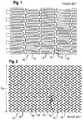
- FIGS. 1 and 2show, respectively content of FIGS. 6 and 2 of US/2003/0055485, being a tubular stent structure opened out flat, seen in plan view, in respectively the radially compact and radially expanded dispositions;
- FIG. 3is a reproduction of FIG. 5 of U.S. Pat. No. 7,223,283, being a portion of a tubular stent structure, opened out flat, and in a radially expanded configuration;
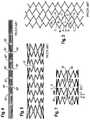
- FIGS. 4 and 5reproduce drawing FIGS. 3 and 4 of applicant's WO 01/32102, being respectively side views of a stent structure in the radially compact and radially expanded dispositions;
- FIGS. 6 and 7are corresponding views of a stent structure in accordance with the present invention.
- FIGS. 8 and 9are views corresponding to those of FIGS. 4 and 5 , or FIGS. 6 and 7 , showing another embodiment of the present invention.
- FIGS. 1 to 5give only the most cursory impression of the wealth of stent strut matrix proposals contained within the state of the art. However, they provide enough disclosure to set the advantages of the present invention in the context of relevant prior art.
- FIGS. 1 and 2we see an example of a stent 10 which utilises circumferential support structures 12 in the form of zig-zag stenting rings. These are spaced apart along the long axis of the stent. They are made up of struts 12 interspersed by points of inflection 18 which US/2003/0055485 designates “apex portions”. These apex portions are mostly free to take up positions, in the expanded FIG. 2 disposition of the stent, which are governed only by the stresses transmitted through the struts of that particular stenting ring, or transmitted to that stenting ring by the bodily tissue that presses against it.
- connecting struts 16each of which joins a selected one of the apex portions of one stenting ring with a selected apex portion of an adjacent stenting ring. From FIG. 1 , we see that the connecting struts have length direction that is in the circumferential direction of the stent tube, so that the opposite ends of each particular connecting strut 16 are circumferentially spaced from each other. In the radially compact disposition of FIG. 1 , the circumferentially extending connecting strut 16 spans an intervening apex portion between its two ends. However, when the stent expands into its radially expanded configuration represented by FIG.
- the circumferential length of the connecting strut 16is not enough to span across an intervening apex portion, because the apex portions arranged around the circumference of any particular stenting ring have moved away from each other by an amount greater than the length of the connecting strut.
- the facing apex portions on the inside of the bend, or that approach each other as the stent is longitudinally compresseddo not butt up against each other but, instead, move into the free gap between two spaced apart apex portions of the other of the two facing stenting rings.
- FIG. 3corresponds to FIG. 5 of U.S. Pat. No. 7,223,283.
- the connector portions between adjacent zig-zag stenting ringshave a very simple construction. They are remarkably short in length but, to the extent that they have a length direction, it is parallel to the longitudinal axis of the stent, rather than in a circumferential direction. Accordingly, there is no circumferential offset between the apex portions facing each other and connected by the connector strut 24 .
- each connector 24is at the apex of a first pair of relatively long struts and a second pair of relatively short struts.
- Each stenting ringfeatures struts of three different lengths, namely A) short, B) intermediate length and C) long.
- FIG. 3how the strut length progresses around the circumference of each stenting ring in a sequence ABCCBA.
- the apex portions at the open end of a bifurcation between two A-strutsboth fall within a single gap between two C-struts of the adjacent stenting ring. This overlap occurs periodically around the circumference of the prosthesis, on each occasion midway between two adjacent connector portions 24 .
- apex portionsare “head-to-head” or “peak-to-peak” all the way around the circumference of the stenting cylinder, not just at those locations where a connector portion 24 lies between the head-to-head apex portions.
- there is reduced flexibility in the compact delivery disposition of the stent devicecomparable with that of the device of FIG. 1 described above. Again, it is not immediately evident how the device delivers bent flexibility in the compact delivery disposition.
- the present applicantseeks in self-expanding stent devices that are formed from a tubular workpiece of nickel titanium shape memory alloy (“NITINOL” trademark).
- the tubeis formed into a stent precursor by forming in it a multiplicity of slits (cut by a laser) that it is convenient to provide all mutually parallel to each other and to the long axis of the tubular workpiece.
- NITINOLnickel titanium shape memory alloy
- FIG. 4This corresponding to FIG. 3 of applicant's earlier publication WO 01/32102, the contents of which are hereby incorporated by reference.
- Reference to the WO documentwill reveal how, following laser cutting, portions of the tubular workpiece are removed to leave “holes” in the slitted tube, indicated by reference 60 in FIG. 4 .
- FIG. 5shows the expanded disposition of the FIG. 4 stent construction.
- a pattern of zig-zag stenting rings connected by short connecting portions 62can be readily recognised and it can also be seen that the apex portions (here in designated “points of inflection”) of adjacent zig-zag stenting rings are facing each other, not only across the connected 62 but also elsewhere around the circumference of the stenting device.
- points of inflectionhere in designated “points of inflection”
- FIG. 6shows a distribution of slits in a tubular workpiece opened out flat, and the similarity with the slit distribution of FIG. 4 is immediately apparent.
- FIG. 4is a view from the side of the workpiece, and does not show the workpiece opened out flat
- FIG. 6shows the entire circumference of the tubular workpiece, laid out flat on the page.
- FIG. 6there are two connecting struts 80 connecting any two adjacent stenting rings 82 .
- the terminal stenting ring 84which has a longer slit length and is also evident in FIG. 4 .
- FIG. 4shows the entire length of the stent whereas FIG.
- FIG. 6shows only a portion of the length of the stent.
- the connectors 80are interspersed by voids 60 just as in FIG. 4 , there are no voids between the increased length end stenting ring 84 and its next adjacent normal length stenting ring 82 ′.
- there are two connector portions 80 between the normal length stenting ringsthere are 14 connectors 86 between the end stenting ring 84 and its neighbour 82 ′.
- FIG. 6Noteworthy in FIG. 6 is the pattern of length of the individual slits cut by the laser.
- the slitshave a single length, but there are two exceptions.
- the first exceptionis that the slit length is longer at the end of the tubular workpiece, to form the end stenting ring 84 .
- One such slitis marked in FIG. 6 with reference 88 .
- the second exceptionis the length of the slit that terminates at one end of each connector portion 80 .
- One such slit, of shorter length then the others,is designated in FIG. 6 with reference 90 .
- FIG. 7We need to look at FIG. 7 to appreciate the consequence of short struts 90 .
- FIG. 7reveals two of the many connector portions 80 .
- Each connector 80sits between two adjacent stenting rings at the points of inflection 92 of any one stenting ring are all to be found on a notional circular locus that is transverse to the longitudinal axis of the stent.
- a gap “t”exists between any particular such circular loci D and E facing each other at periodical intervals down the length of the stent.
- the origin of the circumferential offsetcan be seen in the opposing relationship of the points of inflection 92 A, B, C and D.
- the gap between apex 92 B and 92 C on the stenting ring that includes circle Gis the regular gap between two struts of “normal” length.
- the circumferential gap between points of inflection 92 A and 92 Dis abnormally small so that both points of inflection 92 A and 92 D “fit” in the normal sized gap between apex 92 B and 92 C of circle G.
- the zone that includes points of inflection 92 A, B, C and Dis designated a stagger zone. From FIG. 7 it is immediately evident that providing such a stagger zone by using an abnormally short slit length has a disadvantage, namely, that the gap between points of inflection 92 A and 92 D is shorter than the regular gaps between other points of inflection spaced around circle F. It hardly need be stated that optimal use of material within a stent matrix calls for a regular matrix of struts, with a minimal amount of material in the radially compact delivery disposition, and a uniformed distribution of that material in the expanded configuration (all gaps the same size) so as to achieve a maximum ratio of expanded diameter to radially compress delivery diameter. Deliberately accepting a plurality of unnecessarily small gaps around the circumference of each stenting ring will have an adverse effect on this ratio of diameters and is therefore not something of itself desirable to stent designers.
- the present inventionis attractive, when taken in the context of balancing conflicting constraints on the stent designer.
- FIG. 6one can see the evident simplicity of the stent strut and slit arrangement.
- the government regulatory authoritiesimpose stringent quality requirements on stent manufacturers.
- stentsmust meet stringent metal fatigue requirements.
- Finite element analysis of stent designsis of crucial importance.
- a design that is inherently simpleshould lend itself to reliable prediction of its properties in service. Being able to predict how a stent will perform after it has been installed in a human body is a significant advantage for stent manufacturers that compete to provide the stents most attractive to doctors and medical services.
- FIGS. 8 and 9These have been annotated with references the same as are used in FIGS. 6 and 7 , to identify corresponding features. Noteworthy is that there are four connectors rather than two, connecting adjacent stenting rings. Clearly, each stent ring comprises pairs of struts which are unconnected to any pairs of struts of an adjacent stent ring. Further is clear that a number of adjacent stent rings are spaced from each other.
- FIG. 8shows the left-hand end of the stent whereas FIG. 9 shows the full length. Actually, the FIG. 9 stent is not the same as the FIG. 8 stent because FIG. 8 shows longer struts in the two end rings but FIG. 9 does not.
- connectors 80 A and 80 Bhave the asymmetric shape of all the other connectors of zig-zag rings 82 .
- the latterhas an X shape because it is part of the transition from the stagger zone rings 82 to the end ring 84 that lacks any stagger zone. Shown is that the closest end points of a pair of struts of one stent ring and a pair of struts of another stent ring are connected.
- FIGS. 6 to 9represent only one of a multitude of ways to bring about an angle between struts that is different from the otherwise regular angle between struts around the remainder of the circumference of any particular stenting ring.
- Above-mentioned WO 01/32102contemplates manual removal of individual scrap portions to create voids 60 . There are voids 60 in FIG. 6 .
- the materialcould be modified in its composition, by local application of a substance to cause a chemical reaction, or by local application of a substance to modify the microstructure of the material at that point, or by local application of heat or cooling to give the material at that location a different thermal history of that of the material of the remainder of the stenting ring.
- the realityis that, as stent designs become ever more sophisticated, so the range of applications for stents becomes ever greater and, with that, the demand for stents to mimic ever more closely the flexible behaviour of the original bodily tissue, especially when called upon, from time to time, to bend tightly along its length.
- the challengeis to build a stent that is strong enough to perform the stenting function which is after all the reason for its surgical implantation in the body while, at the same time, rendering the prosthesis as soft and bendy as possible in all other aspects.
- the present inventionmakes a valuable contribution to this objective.
- Stentsneed not be made of nickel titanium alloy. Another biologically compatible material familiar to stent designers is stainless steel. Great efforts are currently being made to use other materials such as biologically compatible polymers. All such stents can benefit from the present invention regardless how they are formed. The illustrated embodiments are not limiting.
- Stentsneed not display the same strut matrix over their entire length.
Landscapes
- Health & Medical Sciences (AREA)
- Engineering & Computer Science (AREA)
- Biomedical Technology (AREA)
- Heart & Thoracic Surgery (AREA)
- Life Sciences & Earth Sciences (AREA)
- Cardiology (AREA)
- Oral & Maxillofacial Surgery (AREA)
- Transplantation (AREA)
- Veterinary Medicine (AREA)
- Vascular Medicine (AREA)
- Public Health (AREA)
- Animal Behavior & Ethology (AREA)
- General Health & Medical Sciences (AREA)
- Optics & Photonics (AREA)
- Physics & Mathematics (AREA)
- Media Introduction/Drainage Providing Device (AREA)
- Prostheses (AREA)
Abstract
Description
This application is a continuation of U.S. patent application Ser. No. 14/881,043, filed Oct. 12, 2015, now U.S. Pat. No. 9,956,098, which is a continuation of U.S. patent application Ser. No. 13/849,312, filed Mar. 22, 2013, now U.S. Pat. No. 9,155,642, which is a continuation of U.S. patent application Ser. No. 12/300,985, filed as a U.S. national stage application under 35 USC § 371 of International Application No. PCT/EP2007/004407, filed May 16, 2007, now U.S. Pat. No. 8,403,978, which claims priority to United Kingdom Patent Application No. 0609841.2, filed May 17, 2006, each of which is incorporated by reference in its entirety into this application.
This invention relates to tubular medical prostheses that are expandable from a radially compact disposition to a radially expanded disposition. In the compact disposition, the prosthesis can by delivered to its operational site in the body, typically trans-luminally and percutaneously, using a delivery system which is a sort of catheter. Exemplary of this class of prosthesis is a nickel titanium shape memory alloy stent for a bodily lumen which is often but not always an arterial lumen. See for example the disclosure of applicant's earlier WO 01/32102.
Bodily soft tissue is remarkably flexible and needs generally to be flexible. It is difficult for a metal stent to match bodily tissue for flexibility. WO 01/32102 is concerned with flexibility of the stent during its journey, from outside the body to the operational site within the body, as for example the catheter delivery system advances along a tortuous path from the point of entry in the body. However, there is also a need for metal stents (and other prostheses) that are destined to be installed at a location in the body where severe bending is to be expected. If the prosthesis could be made more tolerant of severe bending after placement, that would be attractive to doctors and their patients.
WO 01/32102 shows what could be termed a “classic” self-expanding stent structure of zig-zag stenting rings composed of struts interspersed by points of inflection and with adjacent stenting rings linked axially by connector portions. In the compact delivery disposition of the stent (FIG. 3 of WO 01/32102) the struts of the zig-zag rings are more or less parallel to each other so that each point of inflection represents a change of direction for the material of the stenting ring of more or less 180°. As the stent expands to its deployed configuration (FIG. 4 of WO 01/32102) the radius of the stenting ring expands by movement of the struts away from each other so that gaps open up between adjacent struts, and the adjacent points of inflection move further apart (but nevertheless remain spaced at equal intervals to each other around the circumference of the stenting ring).
The connectors serve to restrain relative circumferential movement of the zig-zag rings relative to each other. Thus, if the points of inflection of adjacent stenting rings are facing each other in the compact delivery disposition of the stent, as in WO 01/32102, then so will be these points of inflection still facing each other in the expanded disposition of the stent. When an expanded stent is subject, in the body, to extreme bending, so that the longitudinal axis of the stent is no longer a straight line but a pronounced curve (as in a banana), then the facing points of inflection on the inside of the bend approach each other. The more extreme the bending, the closer the facing points of inflection become until, in the end, these facing “peaks” abut each other or rub past each other.
Any such abutment or rubbing is undesirable. One way to guard against it is to choose a stent design that can be classified as a “peak-to-valley” design rather than a “peak-to-peak” design as seen in applicant's WO 01/32102. The art is replete with suggestions for peak-to-valley designs in which the peaks of any one zig-zag stenting ring do not face corresponding peaks of the next adjacent stenting ring but, instead, are circumferentially offset to the peaks of the next adjacent stenting ring by half of the gap between two adjacent peaks of the same ring, in the expanded disposition of the stent. Then, under extreme bending, any particular peak on the inside of the bend can advance into the V-shaped space between two peaks of the next adjacent stenting ring, without any abutment or rubbing on any portion of the material of the next adjacent stenting ring.
The present invention is concerned with the above-explained problem. It seeks to improve the in situ bend capability of stents including those seen in WO 01/32102. However, the invention also seeks to achieve this performance enhancement without sacrificing other attractive qualities of stents such as disclosed in WO 01/32102. For example, simplicity of modelling of stress distributions within the stent is attractive in the management of fatigue performance of metal stents. Manufacturing simplicity of course facilitates management of cost which should improve access to stents, for those people who need them.
Looking at WO 01/32102, one can quickly see that performance in extreme bending could be enhanced by extending the length of the portions that connect adjacent zig-zag stenting rings. The longer these “bridges” then the more the stent can bend without abutment of peaks on the inside of the bend. However, large axial gaps between adjacent stenting rings are not desirable, for then the tissue of the lumen that is being stented by the prosthesis is relatively unsupported, at least between adjacent stenting rings.
For the same reason, one seeks as far as possible to distribute the metallic material of the stent as evenly as possible over the length and circumference of the tubular envelope of the stent so that support for the stented tissue is as even and uninterrupted as possible. This of course indicates that all gaps between all adjacent struts and points of inflection of the stent matrix should be as constant as possible. Generally, one does not modulate the strut matrix of a stent, over the length and circumference of the stent, to suit tissue variations within the stenting site. Generally, one does not seek to place a particular point on the circumference of the stent in opposition to a particular zone of tissue within the stenting site. For these reasons alone, one seeks a stent matrix that is everywhere the same over the length and circumference of the prosthesis.
In principle, the problem addressed in the present invention, and the solution here disclosed, is useful in all classes of stenting prostheses. That is to say, it works with a stent matrix that exhibits the (spiral) turns around the axis of a helical stent, as well as with a stent that features a stack of endless stenting rings. It works with balloon-expandable stents and resilient self-expanding stents as well as with nickel titanium shape memory alloy stents.
Nevertheless, according to the present invention, it is contemplated to depart from the prior good design practice, and deliberately configure the stent matrix so that it is locally different, at one point at least, around the circumference of at least every second stenting ring within the prosthesis. In short, we envisage within each stenting ring at least one location (we call it a “stagger zone”) where the gap between adjacent points of inflection is smaller (but it could be greater) than the otherwise constant (or near constant) “wavelength” around the circumference of the prosthesis for that particular stenting ring.
It will be appreciated that, for any particular pair of adjacent stenting rings, even just one such abnormal gap (stagger zone) could be enough to set up a circumferential offset between the otherwise facing “peak-to-peak” points of inflection that we see in, for example, FIG. 4 of WO 01/32102. In practice, however, a design with only one stagger zone on the circumference might not be enough to deliver the desired circumferential offset all around the circumference, especially in designs that feature a large number of struts, in any one turn around the axis of the prosthesis. Four stagger zones are likely to be enough. Designs with two, three or four such zones are presently preferred, but up to 6 stagger zones per turn are readily conceivable, the more so with stent design with a notably small mesh size in their matrix.
As mentioned above, it is the connectors between adjacent stenting rings that prevent adjacent stenting rings from rotating around the long axis of the prosthesis relative to each other and thereby preserve the designed intended relationship between facing stenting rings and their respective points of inflection. Generally, it will be convenient to incorporate the design variation that creates the abnormal gap between adjacent points of inflection with the design of the connector zone between two adjacent turns. Thus, in perhaps the simplest case, we can envisage a connector from which two struts extend into a stenting ring or turn on one side of the connector, and two other struts extend in the other axial direction, into the next adjacent stenting ring or turn. If the angle between the first two struts is “normal” for that stenting ring, but the angle between the opposite pair of struts, in the other of the two stenting rings, is much smaller than “normal”, then the points of inflection circumferentially on either side of the connector, that would be facing each other in the classic construction of WO 01/32102, will be circumferentially offset from each other, because of the different angle of the struts each side of the connector. Think of the connector as the trunk of a human body, with the legs of the body slightly open and the two arms of the body. Imagine the angle between the upwardly outstretched arms significantly greater than the angle between the legs.
Rather than set out a string of statements of invention, and then repeat them in a set of claims, we opt for economy of text, refrain from reciting statements of invention, and present various aspects of the above explained inventive concept in claims appended to this description.
We have stated that setting up a “peak-to-valley” configuration of otherwise facing inflection zones is conveniently incorporated in the design of portions that connect adjacent stenting rings (or helical turns). However, one can readily envisage that the necessary offset can be created in a stagger zone that is circumferentially spaced from connectors. There is no imperative that the stagger zone must be coincident with the connector zone.
It will be evident that a stagger zone can be created in a number of different ways. One can locally manipulate the mechanical properties of the material of the stagger zone, not just be local modulation of the dimensions of the inflection points or struts within the stagger zone, relative to the rest of the circumference of the stenting ring, but could also contemplate manipulation of the mechanical properties of the material in the stagger zone by local heat treatment or even chemical treatment. It is even possible to envisage adding components to an otherwise “classic” stenting ring structure as in WO 01/32102, such as a flexible “tie” between the two struts that are destined to deliver a smaller than usual gap between adjacent points of inflection. When a painter erects an easel, there is a “piece of string” that runs between the front frame of the easel, and the rear strut of the easel, not far above the ground, where the gap between the front legs of the easel and the single rear leg of the easel rest on the ground. A classic stent such as shown in WO 01/32102 could be modified by inclusion in it of judiciously placed “pieces of string” from biologically compatible material, in order to restrain two adjacent struts of selected stenting rings of the prosthesis from opening to the full extent that occurs for all the other struts of that particular stenting ring. (We mention this possibility not with any expectation that it will be a preferred construction, but in the recognition that competitors stimulated by the present disclosure might be obliged to turn to such constructions in the hope of avoiding the inventive concept of the present application). The motto “keep it simple” is rather powerful and the present inventors are proud of a contribution to the art that is essentially simple but should deliver a powerful enhancement of performance.
At this juncture, it is worth noting that a shape memory alloy stent is given its “remembered” configuration by a heat treatment. In the case of WO 01/32102, that heat treatment is given with the points of inflection arranged “peak-to-peak”. With shape memory alloy stents embodying the present invention, however, the heat treatment is with the inflection points arranged as intended, therefore, not peak to peak, but in the circumferentially staggered arrangement brought about by the stagger zone(s).
In the context of the present invention, attention is directed to the disclosure of U.S. Pat. No. 7,223,283 and, in particular, drawingsFIGS. 4 and 5 and the associated text. We see adjacent zig-zag stenting rings with points of inflection that are more or less “peak-to-peak” in the compact configuration of drawingFIG. 4 , but not so much peak-to-peak in the expanded configuration of drawingFIG. 5 . However, the struts of any particular zig-zag stenting ring are not all the same length. Some are relatively long, some are relatively short, and some are of intermediate length. By contrast, it appears that the angle that opens up between any two struts that diverge from any particular point of inflection is always the same, so that any technical effect of circumferential displacement of peak-to-peak points of inflection is accomplished not by local variation of an angle between two adjacent struts but, rather, by modulations of the length of adjacent struts in each of the stenting rings. Putting it another way, eachconnector portion 24 is the intersection of two straight lines in the form of an “X” shape and this is not what is envisaged with the present invention.
Thinking about the bend capability of any particular stent design, this might be limited by peak to peak abutment on the inside of the (banana) bend but could also be restricted by incipient buckling of the stent matrix at some point on the matrix. Clearly, to obtain benefit from the present invention, the stent matrix to which it is to be applied must be capable of bending without buckling, to the extent needed to bring the benefits of the present invention into play. In general, the sparser the population of connectors, the more capacity the lattice will have to bend without buckling.
For a better understanding of the present invention, and to show more clearly how the same may be carried into effect, reference will now be made, by way of example, to the accompanying drawings, in which:
Looking first atFIGS. 1 and 2 , we see an example of astent 10 which utilisescircumferential support structures 12 in the form of zig-zag stenting rings. These are spaced apart along the long axis of the stent. They are made up ofstruts 12 interspersed by points ofinflection 18 which US/2003/0055485 designates “apex portions”. These apex portions are mostly free to take up positions, in the expandedFIG. 2 disposition of the stent, which are governed only by the stresses transmitted through the struts of that particular stenting ring, or transmitted to that stenting ring by the bodily tissue that presses against it. However, there are also connectingstruts 16 each of which joins a selected one of the apex portions of one stenting ring with a selected apex portion of an adjacent stenting ring. FromFIG. 1 , we see that the connecting struts have length direction that is in the circumferential direction of the stent tube, so that the opposite ends of each particular connectingstrut 16 are circumferentially spaced from each other. In the radially compact disposition ofFIG. 1 , the circumferentially extending connectingstrut 16 spans an intervening apex portion between its two ends. However, when the stent expands into its radially expanded configuration represented byFIG. 2 , the circumferential length of the connectingstrut 16 is not enough to span across an intervening apex portion, because the apex portions arranged around the circumference of any particular stenting ring have moved away from each other by an amount greater than the length of the connecting strut. By selecting a connecting strut length that is approximately half the distance between two adjacent apex portions of the same stenting ring, in the expanded configuration of the stent, one can achieve a “staggering” of the evenly spaced apex portions of one stenting ring, relative to the equal spacing of the apex portions of the next adjacent stenting ring that “faces” the stenting ring of the other end of the connecting strut.
In consequence, when the stent in its expanded configuration is subject to longitudinal compression, or when it is bent sharply (so that its longitudinal axis is not longer straight but arcuate) the facing apex portions on the inside of the bend, or that approach each other as the stent is longitudinally compressed do not butt up against each other but, instead, move into the free gap between two spaced apart apex portions of the other of the two facing stenting rings.
In US/2003/0055485, paragraph 0031, it is stated that the geometry of the stent in the radially compact delivery disposition ofFIG. 1 is “highly flexible” so that it can tolerate axial compression on the inside of a bend as described above. Looking atFIG. 1 (FIG. 6 of the US publication) it is not immediately evident how the stated flexibility is provided.
We turn now toFIG. 3 , which corresponds to FIG. 5 of U.S. Pat. No. 7,223,283. In this case, one can see that the connector portions between adjacent zig-zag stenting rings have a very simple construction. They are remarkably short in length but, to the extent that they have a length direction, it is parallel to the longitudinal axis of the stent, rather than in a circumferential direction. Accordingly, there is no circumferential offset between the apex portions facing each other and connected by theconnector strut 24.
Nevertheless, we see fromFIG. 3 , that there is a circumferential offset between unconnected apex portions of adjacent stenting rings.
The offset is accomplished by providing a range of different strut lengths in any particular stenting ring. In particular, eachconnector 24 is at the apex of a first pair of relatively long struts and a second pair of relatively short struts. Each stenting ring features struts of three different lengths, namely A) short, B) intermediate length and C) long. And we see fromFIG. 3 how the strut length progresses around the circumference of each stenting ring in a sequence ABCCBA. We can see how the apex portions at the open end of a bifurcation between two A-struts both fall within a single gap between two C-struts of the adjacent stenting ring. This overlap occurs periodically around the circumference of the prosthesis, on each occasion midway between twoadjacent connector portions 24.
In the compact disposition of the stent ofFIG. 3 , apex portions are “head-to-head” or “peak-to-peak” all the way around the circumference of the stenting cylinder, not just at those locations where aconnector portion 24 lies between the head-to-head apex portions. In this respect, there is reduced flexibility in the compact delivery disposition of the stent device, comparable with that of the device ofFIG. 1 described above. Again, it is not immediately evident how the device delivers bent flexibility in the compact delivery disposition.
The present applicant specialises in self-expanding stent devices that are formed from a tubular workpiece of nickel titanium shape memory alloy (“NITINOL” trademark). The tube is formed into a stent precursor by forming in it a multiplicity of slits (cut by a laser) that it is convenient to provide all mutually parallel to each other and to the long axis of the tubular workpiece. One such construction can be seen inFIG. 4 , this corresponding toFIG. 3 of applicant's earlier publication WO 01/32102, the contents of which are hereby incorporated by reference. Reference to the WO document will reveal how, following laser cutting, portions of the tubular workpiece are removed to leave “holes” in the slitted tube, indicated byreference 60 inFIG. 4 . It will be grasped by the skilled reader that provision of these voids in the slitted tube endows the tube, in its delivery system, confined by a sheath that prevents premature self-expansion, greater flexibility for the sheath to advance along a tortuous delivery path to a site of stenting in the body.
One embodiment of the present invention, which does succeed in setting the facing points of inflection of adjacent stenting rings circumferentially offset from each other, will now be described be reference to drawingsFIGS. 6 and 7 .
Noteworthy inFIG. 6 is the pattern of length of the individual slits cut by the laser. In general, the slits have a single length, but there are two exceptions. The first exception is that the slit length is longer at the end of the tubular workpiece, to form theend stenting ring 84. One such slit is marked inFIG. 6 withreference 88. The second exception is the length of the slit that terminates at one end of eachconnector portion 80. One such slit, of shorter length then the others, is designated inFIG. 6 withreference 90. We need to look atFIG. 7 to appreciate the consequence ofshort struts 90.
Turning our attention to the next adjacent pair of facing circles F and G inFIG. 7 , the origin of the circumferential offset can be seen in the opposing relationship of the points of inflection92A, B, C and D. The gap between apex92B and92C on the stenting ring that includes circle G is the regular gap between two struts of “normal” length. However, because of the reducedslit length 90, the circumferential gap between points of inflection92A and92D is abnormally small so that both points of inflection92A and92D “fit” in the normal sized gap between apex92B and92C of circle G. In the terminology adopted in the present specification, the zone that includes points of inflection92A, B, C and D is designated a stagger zone. FromFIG. 7 it is immediately evident that providing such a stagger zone by using an abnormally short slit length has a disadvantage, namely, that the gap between points of inflection92A and92D is shorter than the regular gaps between other points of inflection spaced around circle F. It hardly need be stated that optimal use of material within a stent matrix calls for a regular matrix of struts, with a minimal amount of material in the radially compact delivery disposition, and a uniformed distribution of that material in the expanded configuration (all gaps the same size) so as to achieve a maximum ratio of expanded diameter to radially compress delivery diameter. Deliberately accepting a plurality of unnecessarily small gaps around the circumference of each stenting ring will have an adverse effect on this ratio of diameters and is therefore not something of itself desirable to stent designers.
Nevertheless, the present invention is attractive, when taken in the context of balancing conflicting constraints on the stent designer. Looking atFIG. 6 , one can see the evident simplicity of the stent strut and slit arrangement. The government regulatory authorities impose stringent quality requirements on stent manufacturers. For example, stents must meet stringent metal fatigue requirements. Finite element analysis of stent designs is of crucial importance. A design that is inherently simple should lend itself to reliable prediction of its properties in service. Being able to predict how a stent will perform after it has been installed in a human body is a significant advantage for stent manufacturers that compete to provide the stents most attractive to doctors and medical services.
Reference is now made toFIGS. 8 and 9 . These have been annotated with references the same as are used inFIGS. 6 and 7 , to identify corresponding features. Noteworthy is that there are four connectors rather than two, connecting adjacent stenting rings. Clearly, each stent ring comprises pairs of struts which are unconnected to any pairs of struts of an adjacent stent ring. Further is clear that a number of adjacent stent rings are spaced from each other.FIG. 8 shows the left-hand end of the stent whereasFIG. 9 shows the full length. Actually, theFIG. 9 stent is not the same as theFIG. 8 stent becauseFIG. 8 shows longer struts in the two end rings butFIG. 9 does not.
InFIG. 9 , it is helpful to considerconnectors 80A and80B. The former has the asymmetric shape of all the other connectors of zig-zag rings82. The latter has an X shape because it is part of the transition from the stagger zone rings82 to theend ring 84 that lacks any stagger zone. Shown is that the closest end points of a pair of struts of one stent ring and a pair of struts of another stent ring are connected.
The embodiments illustrated inFIGS. 6 to 9 represent only one of a multitude of ways to bring about an angle between struts that is different from the otherwise regular angle between struts around the remainder of the circumference of any particular stenting ring. For example, one could locally modify the material of the stenting ring, either in the points of inflection at one or both ends of the struts that are to form the abnormal size gap, or by judicious modification of the dimensions of those points of inflection or the two struts running between them. Above-mentioned WO 01/32102 contemplates manual removal of individual scrap portions to createvoids 60. There arevoids 60 inFIG. 6 . If manual intervention is to be relied upon to create thevoids 60 in an embodiment of the present invention, then it would not be beyond the bounds of imagination to intervene locally, and manually, at portions of the abluminal surface of the workpiece where the properties of the material are to be modified locally in order to deliver a gap of different size, or angle of different size, between two adjacent struts of any particular stenting ring. One envisages that the material could be modified in its composition, by local application of a substance to cause a chemical reaction, or by local application of a substance to modify the microstructure of the material at that point, or by local application of heat or cooling to give the material at that location a different thermal history of that of the material of the remainder of the stenting ring.
In this context, we incorporate, by reference to it, the disclosure of WO2001/076508, from the present applicant, which explains how particular strut configurations can be created by using a jig to hold the workpiece in a particular desired configuration during the heat treatment which “sets” the “remembered” configuration of the struts in the shape memory alloy. Thinking along these lines, one could use instead of struts of different lengths a jig that holds the struts in a configuration such as is shown inFIG. 7 , when giving the workpiece its “remembered” configuration, so that it should open up at the stenting site to the remembered disposition even if the length ofslit 90 is just the same as the length of all the other slits in the stenting ring.
When thinking of workpieces of every day household dimensions, such as how to prevent a door opening too far, one would use a strut between the door and the frame that has a set length corresponding to the maximum opening that one wishes to impose on the door. In the same way, one could envisage some sort of collapsing tie to impose a maximum size on the gap between points of inflection92A and92D, that extends between the respective struts between theslit 90. Of course, stents are very small, but by no means as small as the nanometer dimensions that are in the minds of designers of medical devices, so there seems no justification for dismissing such tie pieces as impracticable. The reality is that, as stent designs become ever more sophisticated, so the range of applications for stents becomes ever greater and, with that, the demand for stents to mimic ever more closely the flexible behaviour of the original bodily tissue, especially when called upon, from time to time, to bend tightly along its length. The challenge is to build a stent that is strong enough to perform the stenting function which is after all the reason for its surgical implantation in the body while, at the same time, rendering the prosthesis as soft and bendy as possible in all other aspects. The present invention makes a valuable contribution to this objective.
Stents need not be made of nickel titanium alloy. Another biologically compatible material familiar to stent designers is stainless steel. Great efforts are currently being made to use other materials such as biologically compatible polymers. All such stents can benefit from the present invention regardless how they are formed. The illustrated embodiments are not limiting.
Stents need not display the same strut matrix over their entire length. We envisage embodiments in which only part of the length of the prosthesis is given the high flexibility of the present invention. Thus, there may be some turns of the stent matrix that include stagger zones, to deliver flexibility, and other parts of the length of the stent (e.g. end zones, or a mid-length portion) where high flexibility is contra-indicated, and so no stagger zones need be provided in these parts of the stent matrix.
Claims (19)
1. A tubular prosthesis comprising:
at least two helical turns or discrete stenting rings, comprising:
at least two regular struts connected by a regular inflection point forming a regular gap between the regular struts, the regular gap having a first size; and
at least two stagger struts connected by a stagger inflection point forming a stagger gap, the stagger gap having a second size shorter than the first size; and
a bridge linking the at least two helical turns or discrete stenting rings, the bridge connected to the stagger inflection point.
2. The tubular prosthesis ofclaim 1 , wherein the regular inflection point adjacent to the stagger inflection point on a first helical turn or stenting ring is offset from a corresponding regular inflection point on an adjacent helical turn or stenting ring.
3. The tubular prosthesis ofclaim 1 , wherein the bridge is parallel to a longitudinal axis of the tubular prosthesis.
4. The tubular prosthesis ofclaim 3 , wherein a regular strut of the at least two regular struts has a different size than a stagger strut of the at least two stagger struts.
5. The tubular prosthesis ofclaim 4 , wherein the regular inflection point adjacent to the stagger inflection point on a first helical turn or stenting ring is offset from a corresponding regular inflection point on an adjacent helical turn or stenting ring.
6. The tubular prosthesis ofclaim 5 , wherein the tubular prosthesis is a stent.
7. The tubular prosthesis ofclaim 6 , wherein the stent is a self-expanding stent.
8. The tubular prosthesis ofclaim 7 , wherein the stagger inflection point or stagger strut comprises material different from the regular inflection point or regular strut.
9. The tubular prosthesis ofclaim 8 , wherein the difference is a difference in chemical composition.
10. The tubular prosthesis ofclaim 8 , wherein the difference is a difference in crystalline microstructure.
11. The tubular prosthesis ofclaim 5 , wherein the stagger inflection point or stagger strut comprises material different from the regular inflection point or regular strut.
12. The tubular prosthesis ofclaim 11 , wherein the difference is a difference in chemical composition.
13. The tubular prosthesis ofclaim 11 , wherein the difference is a difference in crystalline microstructure.
14. The tubular prosthesis ofclaim 3 , wherein the regular inflection point adjacent to the stagger inflection point on a first helical turn or stenting ring is offset from a corresponding regular inflection point on an adjacent helical turn or stenting ring.
15. The tubular prosthesis ofclaim 14 , wherein the tubular prosthesis is a stent.
16. The tubular prosthesis ofclaim 15 , wherein the stent is a self-expanding stent.
17. The tubular prosthesis ofclaim 16 , wherein the stagger inflection point or stagger strut comprises material different from the regular inflection point or regular strut.
18. The tubular prosthesis ofclaim 17 , wherein the difference is a difference in chemical composition.
19. The tubular prosthesis ofclaim 17 , wherein the difference is a difference in crystalline microstructure.
Priority Applications (1)
| Application Number | Priority Date | Filing Date | Title |
|---|---|---|---|
| US15/966,120US10849770B2 (en) | 2006-05-17 | 2018-04-30 | Bend-capable tubular prosthesis |
Applications Claiming Priority (7)
| Application Number | Priority Date | Filing Date | Title |
|---|---|---|---|
| GB0609841.2 | 2006-05-17 | ||
| GBGB0609841.2AGB0609841D0 (en) | 2006-05-17 | 2006-05-17 | Bend-capable tubular prosthesis |
| PCT/EP2007/004407WO2007131798A1 (en) | 2006-05-17 | 2007-05-16 | Bend-capable tubular prosthesis |
| US30098510A | 2010-08-06 | 2010-08-06 | |
| US13/849,312US9155642B2 (en) | 2006-05-17 | 2013-03-22 | Bend-capable tubular prosthesis |
| US14/881,043US9956098B2 (en) | 2006-05-17 | 2015-10-12 | Bend-capable tubular prosthesis |
| US15/966,120US10849770B2 (en) | 2006-05-17 | 2018-04-30 | Bend-capable tubular prosthesis |
Related Parent Applications (1)
| Application Number | Title | Priority Date | Filing Date |
|---|---|---|---|
| US14/881,043ContinuationUS9956098B2 (en) | 2006-05-17 | 2015-10-12 | Bend-capable tubular prosthesis |
Publications (2)
| Publication Number | Publication Date |
|---|---|
| US20180271684A1 US20180271684A1 (en) | 2018-09-27 |
| US10849770B2true US10849770B2 (en) | 2020-12-01 |
Family
ID=36660371
Family Applications (4)
| Application Number | Title | Priority Date | Filing Date |
|---|---|---|---|
| US12/300,985Active2028-10-17US8403978B2 (en) | 2006-05-17 | 2007-05-16 | Bend-capable tubular prosthesis |
| US13/849,312Active2028-04-13US9155642B2 (en) | 2006-05-17 | 2013-03-22 | Bend-capable tubular prosthesis |
| US14/881,043Active2027-07-06US9956098B2 (en) | 2006-05-17 | 2015-10-12 | Bend-capable tubular prosthesis |
| US15/966,120Active2027-12-10US10849770B2 (en) | 2006-05-17 | 2018-04-30 | Bend-capable tubular prosthesis |
Family Applications Before (3)
| Application Number | Title | Priority Date | Filing Date |
|---|---|---|---|
| US12/300,985Active2028-10-17US8403978B2 (en) | 2006-05-17 | 2007-05-16 | Bend-capable tubular prosthesis |
| US13/849,312Active2028-04-13US9155642B2 (en) | 2006-05-17 | 2013-03-22 | Bend-capable tubular prosthesis |
| US14/881,043Active2027-07-06US9956098B2 (en) | 2006-05-17 | 2015-10-12 | Bend-capable tubular prosthesis |
Country Status (6)
| Country | Link |
|---|---|
| US (4) | US8403978B2 (en) |
| EP (1) | EP2020966B1 (en) |
| JP (1) | JP4827965B2 (en) |
| CA (1) | CA2652214C (en) |
| GB (1) | GB0609841D0 (en) |
| WO (1) | WO2007131798A1 (en) |
Families Citing this family (42)
| Publication number | Priority date | Publication date | Assignee | Title |
|---|---|---|---|---|
| GB0020491D0 (en) | 2000-08-18 | 2000-10-11 | Angiomed Ag | Stent with attached element and method of making such a stent |
| US6878162B2 (en) | 2002-08-30 | 2005-04-12 | Edwards Lifesciences Ag | Helical stent having improved flexibility and expandability |
| US20060074480A1 (en) | 2004-09-01 | 2006-04-06 | Pst, Llc | Stent and method for manufacturing the stent |
| JP2009526572A (en)* | 2006-02-14 | 2009-07-23 | アンギオメット ゲゼルシャフト ミット ベシュレンクテル ハフツング ウント コムパニー メディツィンテヒニク コマンデイトゲゼルシャフト | Highly flexible stent and manufacturing method |
| GB0609841D0 (en) | 2006-05-17 | 2006-06-28 | Angiomed Ag | Bend-capable tubular prosthesis |
| GB0609911D0 (en)* | 2006-05-18 | 2006-06-28 | Angiomed Ag | Bend-capable stent prosthesis |
| GB0616579D0 (en) | 2006-08-21 | 2006-09-27 | Angiomed Ag | Self-expanding stent |
| GB0616999D0 (en) | 2006-08-29 | 2006-10-04 | Angiomed Ag | Annular mesh |
| EP2063824B1 (en) | 2006-09-07 | 2020-10-28 | Angiomed GmbH & Co. Medizintechnik KG | Helical implant having different ends |
| GB0622465D0 (en) | 2006-11-10 | 2006-12-20 | Angiomed Ag | Stent |
| GB0624419D0 (en) | 2006-12-06 | 2007-01-17 | Angiomed Ag | Stenting ring with marker |
| GB0706499D0 (en) | 2007-04-03 | 2007-05-09 | Angiomed Ag | Bendable stent |
| GB0717481D0 (en) | 2007-09-07 | 2007-10-17 | Angiomed Ag | Self-expansible stent with radiopaque markers |
| US10166127B2 (en) | 2007-12-12 | 2019-01-01 | Intact Vascular, Inc. | Endoluminal device and method |
| US9375327B2 (en) | 2007-12-12 | 2016-06-28 | Intact Vascular, Inc. | Endovascular implant |
| US7896911B2 (en) | 2007-12-12 | 2011-03-01 | Innovasc Llc | Device and method for tacking plaque to blood vessel wall |
| US10022250B2 (en) | 2007-12-12 | 2018-07-17 | Intact Vascular, Inc. | Deployment device for placement of multiple intraluminal surgical staples |
| US9603730B2 (en) | 2007-12-12 | 2017-03-28 | Intact Vascular, Inc. | Endoluminal device and method |
| US8128677B2 (en) | 2007-12-12 | 2012-03-06 | Intact Vascular LLC | Device and method for tacking plaque to a blood vessel wall |
| EP2349129B1 (en)* | 2008-10-10 | 2016-05-04 | Veryan Medical Limited | A stent suitable for deployment in a blood vessel |
| US9149377B2 (en) | 2008-10-10 | 2015-10-06 | Veryan Medical Ltd. | Stent suitable for deployment in a blood vessel |
| US20120022578A1 (en)* | 2010-07-20 | 2012-01-26 | Cook Medical Technologies Llc | Frame-based vena cava filter |
| EP2658485B1 (en)* | 2010-12-28 | 2016-10-26 | Boston Scientific Scimed, Inc. | Stent |
| US10285831B2 (en) | 2011-06-03 | 2019-05-14 | Intact Vascular, Inc. | Endovascular implant |
| CN110464520A (en) | 2012-01-25 | 2019-11-19 | 因特脉管有限公司 | Intracavitary unit and method |
| DE102012220129B4 (en)* | 2012-11-05 | 2022-12-15 | Optimed Medizinische Lnstrumente Gmbh | stent |
| US9566633B2 (en)* | 2012-11-15 | 2017-02-14 | Vactronix Scientific, Inc. | Stents having a hybrid pattern and methods of manufacture |
| US9180031B2 (en)* | 2013-03-15 | 2015-11-10 | Covidien Lp | Stent with varying radius between struts |
| US9259335B2 (en) | 2013-03-15 | 2016-02-16 | Covidien Lp | Stent |
| JP6373831B2 (en)* | 2013-05-23 | 2018-08-15 | 学校法人東海大学 | Stent |
| US20150105852A1 (en)* | 2013-10-16 | 2015-04-16 | Covidien Lp | Vascular Stent |
| DE102015100932A1 (en) | 2015-01-22 | 2016-07-28 | Aesculap Ag | Stent retractor / distractor |
| US9433520B2 (en) | 2015-01-29 | 2016-09-06 | Intact Vascular, Inc. | Delivery device and method of delivery |
| US9375336B1 (en) | 2015-01-29 | 2016-06-28 | Intact Vascular, Inc. | Delivery device and method of delivery |
| WO2016210363A1 (en)* | 2015-06-24 | 2016-12-29 | Endologix, Inc. | Endoluminal prosthesis systems and methods |
| KR101810294B1 (en) | 2015-08-31 | 2018-01-25 | 롯데첨단소재(주) | Thermoplastic resin composition having paper texture and molded article produced therefrom |
| US10993824B2 (en) | 2016-01-01 | 2021-05-04 | Intact Vascular, Inc. | Delivery device and method of delivery |
| DE102016118605A1 (en)* | 2016-09-30 | 2018-04-05 | Aesculap Ag | Retractor with puzzle connection |
| US11660218B2 (en) | 2017-07-26 | 2023-05-30 | Intact Vascular, Inc. | Delivery device and method of delivery |
| US10932927B2 (en)* | 2018-08-29 | 2021-03-02 | DePuy Synthes Products, Inc. | Stent with longitudinal variable width struts |
| US20230172731A1 (en)* | 2021-02-25 | 2023-06-08 | Polyrey Medical Tech.(Suzhou) Co., Ltd. | Peripheral vascular stent and prepartion method thereof and application thereof |
| WO2023178090A1 (en)* | 2022-03-15 | 2023-09-21 | Merit Medical Systems, Inc. | Non-foreshortening balloon expandable stent frame |
Citations (168)
| Publication number | Priority date | Publication date | Assignee | Title |
|---|---|---|---|---|
| GB453944A (en) | 1935-04-10 | 1936-09-22 | John Walter Anderson | Improvements in couplings for vehicles |
| US3749878A (en) | 1967-03-16 | 1973-07-31 | Nat Res Dev | Gas assisted laser cutting apparatus |
| US3943324A (en) | 1970-12-14 | 1976-03-09 | Arthur D. Little, Inc. | Apparatus for forming refractory tubing |
| FR2626046A1 (en) | 1988-01-18 | 1989-07-21 | Caoutchouc Manuf Plastique | Device for joining panels or for producing conduits and its applications |
| US5091205A (en) | 1989-01-17 | 1992-02-25 | Union Carbide Chemicals & Plastics Technology Corporation | Hydrophilic lubricious coatings |
| EP0481365A1 (en) | 1990-10-13 | 1992-04-22 | Angiomed Ag | Device for expanding a stenosis in a body duct |
| DE4130431A1 (en) | 1991-09-13 | 1993-03-18 | Liselotte Dr Sachse | Plastics urethral prosthesis - consists of tube and reinforced with metal rings placed in tube mould or fitted within plastics layers of tube |
| US5195984A (en) | 1988-10-04 | 1993-03-23 | Expandable Grafts Partnership | Expandable intraluminal graft |
| WO1994017754A1 (en) | 1993-02-04 | 1994-08-18 | Angiomed Ag | Stent |
| US5345057A (en) | 1993-03-25 | 1994-09-06 | Lasag Ag | Method of cutting an aperture in a device by means of a laser beam |
| WO1995003010A1 (en) | 1993-07-23 | 1995-02-02 | Cook Incorporated | A flexible stent having a pattern formed from a sheet of material |
| US5464419A (en) | 1993-03-22 | 1995-11-07 | Industrial Research B.V. | Expandable hollow sleeve for the local support and/or reinforcement of a body vessel, and method for the fabrication thereof |
| JPH07315147A (en) | 1994-05-23 | 1995-12-05 | Nishikawa Rubber Co Ltd | Drip weather strip mounting structure |
| EP0709068A2 (en) | 1994-10-27 | 1996-05-01 | Medinol Ltd. | X-ray visible stent |
| US5527353A (en) | 1993-12-02 | 1996-06-18 | Meadox Medicals, Inc. | Implantable tubular prosthesis |
| WO1996026689A1 (en) | 1995-03-01 | 1996-09-06 | Scimed Life Systems, Inc. | Improved longitudinally flexible expandable stent |
| US5591223A (en) | 1992-11-23 | 1997-01-07 | Children's Medical Center Corporation | Re-expandable endoprosthesis |
| DE29621207U1 (en) | 1996-12-06 | 1997-01-30 | MAN Roland Druckmaschinen AG, 63075 Offenbach | Fastening a heat sink on a printed circuit board |
| US5645532A (en) | 1996-03-04 | 1997-07-08 | Sil-Med Corporation | Radiopaque cuff peritoneal dialysis catheter |
| WO1997033534A1 (en) | 1996-03-13 | 1997-09-18 | Medtronic, Inc. | Radiopaque stent markers |
| EP0800800A1 (en) | 1996-04-10 | 1997-10-15 | Variomed AG | Stent for transluminal implantation in a hollow organ |
| US5725572A (en) | 1994-04-25 | 1998-03-10 | Advanced Cardiovascular Systems, Inc. | Radiopaque stent |
| US5741327A (en) | 1997-05-06 | 1998-04-21 | Global Therapeutics, Inc. | Surgical stent featuring radiopaque markers |
| WO1998020810A1 (en) | 1996-11-12 | 1998-05-22 | Medtronic, Inc. | Flexible, radially expansible luminal prostheses |
| US5759192A (en) | 1994-11-28 | 1998-06-02 | Advanced Cardiovascular Systems, Inc. | Method and apparatus for direct laser cutting of metal stents |
| EP0847733A1 (en) | 1996-12-10 | 1998-06-17 | BIOTRONIK Mess- und Therapiegeräte GmbH & Co Ingenieurbüro Berlin | Stent |
| US5800511A (en) | 1993-01-19 | 1998-09-01 | Schneider (Usa) Inc | Clad composite stent |
| EP0870483A2 (en) | 1997-03-14 | 1998-10-14 | Nozomu Kanesaka | Flexible stent |
| US5824059A (en) | 1997-08-05 | 1998-10-20 | Wijay; Bandula | Flexible stent |
| US5824042A (en) | 1996-04-05 | 1998-10-20 | Medtronic, Inc. | Endoluminal prostheses having position indicating markers |
| US5843175A (en) | 1997-06-13 | 1998-12-01 | Global Therapeutics, Inc. | Enhanced flexibility surgical stent |
| US5843118A (en) | 1995-12-04 | 1998-12-01 | Target Therapeutics, Inc. | Fibered micro vaso-occlusive devices |
| DE19728337A1 (en) | 1997-07-03 | 1999-01-07 | Inst Mikrotechnik Mainz Gmbh | Implantable stent |
| US5858556A (en) | 1997-01-21 | 1999-01-12 | Uti Corporation | Multilayer composite tubular structure and method of making |
| US5868783A (en) | 1997-04-16 | 1999-02-09 | Numed, Inc. | Intravascular stent with limited axial shrinkage |
| US5876449A (en) | 1995-04-01 | 1999-03-02 | Variomed Ag | Stent for the transluminal implantation in hollow organs |
| WO1999015108A2 (en) | 1997-09-24 | 1999-04-01 | Med Institute, Inc. | Radially expandable stent |
| DE29904817U1 (en) | 1999-03-16 | 1999-05-27 | amg Handelsgesellschaft für angewandte Medizin- und Gesundheitstechnik mbH, 46348 Raesfeld | Blood vessel support device |
| US5922020A (en) | 1996-08-02 | 1999-07-13 | Localmed, Inc. | Tubular prosthesis having improved expansion and imaging characteristics |
| WO1999038457A1 (en) | 1998-02-03 | 1999-08-05 | Jang G David | Tubular stent consisting of horizontal expansion struts and contralaterally attached diagonal-connectors |
| WO1999049928A1 (en) | 1998-03-30 | 1999-10-07 | Conor Medsystems, Inc. | Expandable medical device with ductile hinges |
| WO1999055253A1 (en) | 1998-04-27 | 1999-11-04 | Microval (S.A.R.L.) | Tubular and flexible vascular prosthesis |
| US6022374A (en) | 1997-12-16 | 2000-02-08 | Cardiovasc, Inc. | Expandable stent having radiopaque marker and method |
| US6053940A (en) | 1995-10-20 | 2000-04-25 | Wijay; Bandula | Vascular stent |
| US6056187A (en) | 1996-06-25 | 2000-05-02 | International Business Machines Corporation | Modular wire band stent |
| US6086611A (en) | 1997-09-25 | 2000-07-11 | Ave Connaught | Bifurcated stent |
| US6099561A (en) | 1996-10-21 | 2000-08-08 | Inflow Dynamics, Inc. | Vascular and endoluminal stents with improved coatings |
| WO2000045742A1 (en) | 1999-02-02 | 2000-08-10 | C.R. Bard, Inc. | Covered stent with encapsulated ends |
| EP1029517A2 (en) | 1999-01-14 | 2000-08-23 | Medtronic Inc. | Staggered endoluminal stent |
| WO2000049971A1 (en) | 1999-02-26 | 2000-08-31 | Advanced Cardiovascular Systems, Inc. | Stent with customized flexibility |
| EP1034751A2 (en) | 1999-03-05 | 2000-09-13 | Terumo Kabushiki Kaisha | Implanting stent and dilating device |
| WO2000064375A1 (en) | 1999-04-22 | 2000-11-02 | Advanced Cardiovascular Systems, Inc. | Radiopaque stents |
| WO2001001889A1 (en) | 1999-07-02 | 2001-01-11 | Scimed Life Systems, Inc. | Spiral wound stent |
| US6174329B1 (en) | 1996-08-22 | 2001-01-16 | Advanced Cardiovascular Systems, Inc. | Protective coating for a stent with intermediate radiopaque coating |
| WO2001032102A1 (en) | 1999-10-29 | 2001-05-10 | Angiomed Gmbh & Co. Medizintechnik Kg | Method of making a stent |
| WO2001058384A1 (en) | 2000-02-14 | 2001-08-16 | Angiomed Gmbh & Co. Medizintechnik Kg | Stent matrix |
| WO2001076508A2 (en) | 2000-04-12 | 2001-10-18 | Angiomed Gmbh & Co. Medizintechnik Kg | Self-expanding memory metal stent and method of making it |
| EP1157673A2 (en) | 2000-05-26 | 2001-11-28 | Variomed AG | Stent, position's element and delivery catheter |
| US6325825B1 (en) | 1999-04-08 | 2001-12-04 | Cordis Corporation | Stent with variable wall thickness |
| US20020007212A1 (en) | 1995-03-01 | 2002-01-17 | Brown Brian J. | Longitudinally flexible expandable stent |
| WO2002015820A2 (en) | 2000-08-18 | 2002-02-28 | Angiomed Gmbh & Co. Medizintechnik Kg | Implant with attached element and method of making such an implant |
| EP1190685A2 (en) | 2000-09-22 | 2002-03-27 | Cordis Corporation | Stent with optimal strength and radiopacity characteristics |
| US6379381B1 (en) | 1999-09-03 | 2002-04-30 | Advanced Cardiovascular Systems, Inc. | Porous prosthesis and a method of depositing substances into the pores |
| US6387123B1 (en) | 1999-10-13 | 2002-05-14 | Advanced Cardiovascular Systems, Inc. | Stent with radiopaque core |
| EP1212991A2 (en) | 2000-12-07 | 2002-06-12 | Cordis Corporation | An intravascular device with improved radiopacity |
| WO2002049544A1 (en) | 2000-12-19 | 2002-06-27 | Vascular Architects, Inc. | Biologically active agent delivery apparatus and method |
| US20020116044A1 (en) | 2000-05-22 | 2002-08-22 | Cottone, Robert John | Self-expanding stent |
| US20020116051A1 (en) | 1992-02-21 | 2002-08-22 | Cragg Andrew H. | Intraluminal stent and graft |
| US20020120323A1 (en) | 2001-02-26 | 2002-08-29 | Intratherapeutics, Inc. | Implant delivery system with interlock |
| US6451047B2 (en) | 1995-03-10 | 2002-09-17 | Impra, Inc. | Encapsulated intraluminal stent-graft and methods of making same |
| US20020138136A1 (en) | 2001-03-23 | 2002-09-26 | Scimed Life Systems, Inc. | Medical device having radio-opacification and barrier layers |
| EP1245203A2 (en) | 2001-03-30 | 2002-10-02 | Terumo Kabushiki Kaisha | Stent |
| US6471721B1 (en) | 1999-12-30 | 2002-10-29 | Advanced Cardiovascular Systems, Inc. | Vascular stent having increased radiopacity and method for making same |
| US6475233B2 (en) | 1997-04-08 | 2002-11-05 | Interventional Technologies, Inc. | Stent having tapered struts |
| US6478816B2 (en) | 1998-07-08 | 2002-11-12 | Scimed Life Systems, Inc. | Stent |
| US20020193867A1 (en) | 2001-06-19 | 2002-12-19 | Gladdish Bennie W. | Low profile improved radiopacity intraluminal medical device |
| US20020198589A1 (en) | 2001-06-22 | 2002-12-26 | Leong Veronica Jade | Tessellated stent and method of manufacture |
| US20030055485A1 (en) | 2001-09-17 | 2003-03-20 | Intra Therapeutics, Inc. | Stent with offset cell geometry |
| US6540777B2 (en) | 2001-02-15 | 2003-04-01 | Scimed Life Systems, Inc. | Locking stent |
| US6547818B1 (en) | 2000-10-20 | 2003-04-15 | Endotex Interventional Systems, Inc. | Selectively thinned coiled-sheet stents and methods for making them |
| US6585757B1 (en) | 1999-09-15 | 2003-07-01 | Advanced Cardiovascular Systems, Inc. | Endovascular stent with radiopaque spine |
| WO2003055414A1 (en) | 2001-10-18 | 2003-07-10 | Advanced Stent Technologies, Inc. | Stent for vessel support, coverage and side branch accessibility |
| US20030135254A1 (en) | 1997-01-09 | 2003-07-17 | Maria Curcio | Stent for angioplasty and a production process therefor |
| US20030144729A1 (en) | 2002-01-30 | 2003-07-31 | Scimed Life Systems, Inc. | Stent with wishbone connectors and serpentine bands |
| DE10201151A1 (en) | 2002-01-15 | 2003-07-31 | Qualimed Innovative Med Prod | Surgical stent design of metal strut framework integrates marker between frame struts and of equal or lesser thickness than struts to identifiy stent position throughout service. |
| US6605110B2 (en) | 2001-06-29 | 2003-08-12 | Advanced Cardiovascular Systems, Inc. | Stent with enhanced bendability and flexibility |
| WO2003075797A2 (en) | 2002-03-14 | 2003-09-18 | Angiomed Gmbh & Co. Medizintechnik Kg | Mri compatible stent and method of manufacturing the same_______ |
| US6629994B2 (en) | 2001-06-11 | 2003-10-07 | Advanced Cardiovascular Systems, Inc. | Intravascular stent |
| US20030216807A1 (en) | 2002-05-16 | 2003-11-20 | Jones Donald K. | Intravascular stent device |
| US6652572B2 (en) | 1998-10-05 | 2003-11-25 | Cordis Corporation | Endovascular graft system |
| US20030225448A1 (en) | 2002-05-28 | 2003-12-04 | Scimed Life Systems, Inc. | Polar radiopaque marker for stent |
| US20040015229A1 (en) | 2002-07-22 | 2004-01-22 | Syntheon, Llc | Vascular stent with radiopaque markers |
| US20040034402A1 (en) | 2002-07-26 | 2004-02-19 | Syntheon, Llc | Helical stent having flexible transition zone |
| US20040044401A1 (en) | 2002-08-30 | 2004-03-04 | Bales Thomas O. | Helical stent having improved flexibility and expandability |
| WO2004019820A1 (en) | 2002-08-30 | 2004-03-11 | Advanced Cardiovascular Systems, Inc. | Stent with nested rings |
| US20040054400A1 (en) | 1999-11-12 | 2004-03-18 | Granada Vuan Fernando | Conformable vascular stent |
| WO2004028408A1 (en) | 2002-09-26 | 2004-04-08 | Cardiovasc, Inc. | Stent graft assembly with attached security rings and method of use |
| US20040073291A1 (en) | 2002-10-09 | 2004-04-15 | Brian Brown | Intraluminal medical device having improved visibility |
| US20040073290A1 (en) | 2002-10-09 | 2004-04-15 | Scimed Life Systems, Inc. | Stent with improved flexibility |
| US20040093072A1 (en) | 2002-05-06 | 2004-05-13 | Jeff Pappas | Endoprosthesis for controlled contraction and expansion |
| US20040093073A1 (en)* | 2002-05-08 | 2004-05-13 | David Lowe | Endoprosthesis having foot extensions |
| US20040117002A1 (en) | 2002-12-16 | 2004-06-17 | Scimed Life Systems, Inc. | Flexible stent with improved axial strength |
| EP1433438A2 (en) | 1994-02-09 | 2004-06-30 | Boston Scientific Limited | Endoluminal prosthesis having radiopaque marker |
| WO2004058384A1 (en) | 2002-12-17 | 2004-07-15 | Fluor Corporation | Configurations and methods for acid gas and contaminant removal with near zero emission |
| US6770089B1 (en) | 2000-12-28 | 2004-08-03 | Advanced Cardiovascular Systems, Inc. | Hybrid stent fabrication using metal rings and polymeric links |
| US20040230293A1 (en) | 2003-05-15 | 2004-11-18 | Yip Philip S. | Intravascular stent |
| US20040236409A1 (en) | 2003-05-20 | 2004-11-25 | Pelton Alan R. | Radiopacity intraluminal medical device |
| US6827734B2 (en) | 1994-07-25 | 2004-12-07 | Advanced Cardiovascular Systems, Inc. | High strength member for intracorporeal use |
| US20040254637A1 (en) | 2003-06-16 | 2004-12-16 | Endotex Interventional Systems, Inc. | Sleeve stent marker |
| US20050010275A1 (en) | 2002-10-11 | 2005-01-13 | Sahatjian Ronald A. | Implantable medical devices |
| DE202004014789U1 (en) | 2004-09-22 | 2005-01-27 | Campus Medizin & Technik Gmbh | Stent for implantation into or onto a hollow organ comprises a cutout serving as receptacle for a conical marker element which is X-ray opaque and is oriented radially relative to the stent axis |
| US20050049682A1 (en) | 2003-05-23 | 2005-03-03 | Scimed Life Systems, Inc. | Stents with attached looped ends |
| US20050060025A1 (en) | 2003-09-12 | 2005-03-17 | Mackiewicz David A. | Radiopaque markers for medical devices |
| US6896696B2 (en) | 1998-11-20 | 2005-05-24 | Scimed Life Systems, Inc. | Flexible and expandable stent |
| US20050149168A1 (en) | 2003-12-30 | 2005-07-07 | Daniel Gregorich | Stent to be deployed on a bend |
| WO2005067816A1 (en) | 2004-01-12 | 2005-07-28 | Angiomed Gmbh & Co. Medizintechnik Kg | Mri compatible implant comprising electrically conductive closed loops |
| WO2005072652A1 (en) | 2004-01-27 | 2005-08-11 | Med Institute, Inc. | Anchoring barb for attachment to a medical prosthesis |
| US20050172471A1 (en) | 2004-02-09 | 2005-08-11 | Vietmeier Kristopher H. | Process method for attaching radio opaque markers to shape memory stent |
| US20050182477A1 (en) | 2001-12-20 | 2005-08-18 | White Geoffrey H. | Intraluminal stent and graft |
| US20050184277A1 (en) | 2004-02-19 | 2005-08-25 | Chung Shan Institute Of Science & Technology | Method for preparing arylphosphonite antioxidant |
| US20050222667A1 (en) | 2004-03-31 | 2005-10-06 | Hunt James B | Stent-graft with graft to graft attachment |
| WO2005104991A1 (en) | 2004-05-05 | 2005-11-10 | Invatec S.R.L. | Endoluminal prosthesis |
| US20050278019A1 (en) | 2004-06-09 | 2005-12-15 | Boston Scientific Scimed, Inc. | Overlapped stents for scaffolding, flexibility and MRI compatibility |
| US6979346B1 (en) | 2001-08-08 | 2005-12-27 | Advanced Cardiovascular Systems, Inc. | System and method for improved stent retention |
| WO2006010636A1 (en) | 2004-07-30 | 2006-02-02 | Angiomed Gmbh & Co. Medizintechnik Kg | Flexible intravascular implant |
| WO2006010638A1 (en) | 2004-07-30 | 2006-02-02 | Angiomed Gmbh & Co. Medizintechnik Kg | Medical implant such as a stent |
| US20060030934A1 (en) | 2002-12-24 | 2006-02-09 | Novostent Corporation | Vascular prosthesis having improved flexibility and nested cell delivery configuration |
| WO2006014768A1 (en) | 2004-07-28 | 2006-02-09 | Cook Incorporated | Stent with an end member having a lateral extension |
| WO2006026778A2 (en) | 2004-09-01 | 2006-03-09 | Pst, Llc | Stent and method for manufacturing the stent |
| WO2006025847A2 (en) | 2004-01-09 | 2006-03-09 | United Technologies Corporation | Fanned trailing edge teardrop array |
| US20060054604A1 (en) | 2004-09-10 | 2006-03-16 | Saunders Richard J | Laser process to produce drug delivery channel in metal stents |
| US20060064153A1 (en) | 2004-09-03 | 2006-03-23 | Carl Baasel Lasertechnik Gmbh & Co. Kg | Intravascular stent and method for producing the stent |
| DE102004045994A1 (en) | 2004-09-22 | 2006-03-30 | Campus Gmbh & Co. Kg | Stent for implantation in or around a hollow organ with marker elements made from a radiopaque material |
| WO2006036912A2 (en) | 2004-09-27 | 2006-04-06 | Echobio Llc | Systems, apparatus and methods related to helical, non-helical or removable stents with rectilinear ends |
| US7060093B2 (en) | 2000-10-30 | 2006-06-13 | Advanced Cardiovascular Systems, Inc. | Increased drug-loading and reduced stress drug delivery device |
| WO2006064153A1 (en) | 2004-12-14 | 2006-06-22 | Saint-Gobain Glass France | Complex partition glass consisting of at least two adjacent glass elements, and method for producing said complex partition glass |
| US20060216431A1 (en) | 2005-03-28 | 2006-09-28 | Kerrigan Cameron K | Electrostatic abluminal coating of a stent crimped on a balloon catheter |
| US20060241741A1 (en) | 2003-06-02 | 2006-10-26 | Daniel Lootz | connecting system for connecting a stent to a radiopaque marker and a process for the production of a connection between a stent and two or more radiopaque markers |
| US7135038B1 (en) | 2002-09-30 | 2006-11-14 | Advanced Cardiovascular Systems, Inc. | Drug eluting stent |
| US20060265049A1 (en) | 2005-05-19 | 2006-11-23 | Gray Robert W | Stent and MR imaging process and device |
| US7175654B2 (en) | 2003-10-16 | 2007-02-13 | Cordis Corporation | Stent design having stent segments which uncouple upon deployment |
| EP1767240A1 (en) | 2004-06-25 | 2007-03-28 | Zeon Corporation | Stent |
| US20070112421A1 (en) | 2005-11-14 | 2007-05-17 | O'brien Barry | Medical device with a grooved surface |
| WO2007073413A1 (en) | 2005-12-23 | 2007-06-28 | Boston Scientific Limited | Stent |
| US7273494B2 (en) | 1997-04-29 | 2007-09-25 | Sorin Biomedica Cardio S.R.L. | Stents for angioplasty |
| WO2007131798A1 (en) | 2006-05-17 | 2007-11-22 | Angiomed Gmbh & Co. Medizintechnik Kg | Bend-capable tubular prosthesis |
| CA2651447A1 (en) | 2006-05-18 | 2007-11-29 | Angiomed GmbH & Co. Medizintechnik KG. | Bend-capable stent prosthesis |
| WO2008006830A1 (en) | 2006-07-10 | 2008-01-17 | Angiomed Gmbh & Co. Medizintechnik Kg | Tubular metal prosthesis and method of making it |
| US20080051885A1 (en) | 2000-09-29 | 2008-02-28 | Llanos Gerard H | Medical Devices, Drug Coatings and Methods for Maintaining the Drug Coatings Thereon |
| WO2008022950A1 (en) | 2006-08-23 | 2008-02-28 | Angiomed Gmbh & Co. Medizintechnik Kg | Method of welding a component to a shape memory alloy workpiece with provision of an extra cut for compensating the variations of dimension of workpiece and component |
| WO2008022949A1 (en) | 2006-08-21 | 2008-02-28 | Angiomed Gmbh & Co. Kg Medizintechnik Kg | Self-expanding stent |
| WO2008025762A1 (en) | 2006-08-29 | 2008-03-06 | Angiomed Gmbh & Co. Medizintechnik Kg | Annular mesh |
| WO2008028964A2 (en) | 2006-09-07 | 2008-03-13 | Angiomed Gmbh & Co. Medizintechnik Kg | Helical implant having different ends |
| WO2008055980A1 (en) | 2006-11-10 | 2008-05-15 | Angiomed Gmbh & Co. Medizintechnik Kg | Stent |
| WO2008068279A1 (en) | 2006-12-06 | 2008-06-12 | Angiomed Gmbh & Co. Medizintechnik Kg | Stenting ring with marker |
| US20080188924A1 (en) | 2002-04-01 | 2008-08-07 | Advanced Cardiovascular Systems, Inc. | Hybrid stent and method of making |
| WO2008101987A1 (en) | 2007-02-21 | 2008-08-28 | Angiomed Gmbh & Co. Medizintechnik Kg | Stent with radiopaque marker |
| WO2008119837A2 (en) | 2007-04-03 | 2008-10-09 | Angiomed Gmbh & Co. Medizintechnik Kg | Bendable stent |
| US7479157B2 (en) | 2003-08-07 | 2009-01-20 | Boston Scientific Scimed, Inc. | Stent designs which enable the visibility of the inside of the stent during MRI |
| WO2009030748A2 (en) | 2007-09-07 | 2009-03-12 | Angiomed Gmbh & Co. Medizintechnik Kg | Self-expansible stent with radiopaque markers and method of making such a stent |
| US20090204203A1 (en) | 2008-02-07 | 2009-08-13 | Medtronic Vascular, Inc. | Bioabsorbable Stent Having a Radiopaque Marker |
| US20090264982A1 (en) | 2004-10-15 | 2009-10-22 | Krause Arthur A | Stent with auxiliary treatment structure |
| US7771463B2 (en) | 2003-03-26 | 2010-08-10 | Ton Dai T | Twist-down implant delivery technologies |
| US7772659B2 (en) | 2006-10-23 | 2010-08-10 | Commissariat A L'energie Atomique | Magnetic device having perpendicular magnetization and interaction compensating interlayer |
| US20100204784A1 (en) | 2005-05-16 | 2010-08-12 | Boston Scientific Scimed, Inc. | Medical devices including metallic films |
| US20110245905A1 (en) | 2010-04-06 | 2011-10-06 | Boston Scientific Scimed, Inc. | Endoprosthesis |
| US20110319977A1 (en) | 2010-06-21 | 2011-12-29 | Zorion Medical, Inc. | Bioabsorbable implants |
| US20140014530A1 (en) | 2012-07-13 | 2014-01-16 | Abbott Cardiovascular Systems, Inc. | Methods for passivating metallic implantable medical devices including radiopaque markers |
Family Cites Families (5)
| Publication number | Priority date | Publication date | Assignee | Title |
|---|---|---|---|---|
| US6602281B1 (en)* | 1995-06-05 | 2003-08-05 | Avantec Vascular Corporation | Radially expansible vessel scaffold having beams and expansion joints |
| DE69937415T2 (en)* | 1998-11-20 | 2008-02-14 | Boston Scientific Ltd., St. Michael | Longitudinally flexible and expandable stent |
| US20010047200A1 (en)* | 1999-10-13 | 2001-11-29 | Raymond Sun | Non-foreshortening intraluminal prosthesis |
| JP2005501651A (en)* | 2001-09-10 | 2005-01-20 | メディノール リミテッド | Longitudinal flexible stent [Related application] This application is a continuation-in-part of application No. 09 / 864,389, filed on May 25, 2001, and is filed on February 28, 2001. No. 09 / 795,794, a continuation-in-part application, which is an application of application No. 09 / 516,753 filed on Mar. 1, 2000. Claims priority of provisional application 60 / 202,723 of monthly application. |
| US7618445B2 (en) | 2005-03-30 | 2009-11-17 | Terumo Kabushiki Kaisha | Flexible stent |
- 2006
- 2006-05-17GBGBGB0609841.2Apatent/GB0609841D0/ennot_activeCeased
- 2007
- 2007-05-16JPJP2009510356Apatent/JP4827965B2/enactiveActive
- 2007-05-16CACA2652214Apatent/CA2652214C/enactiveActive
- 2007-05-16WOPCT/EP2007/004407patent/WO2007131798A1/enactiveApplication Filing
- 2007-05-16USUS12/300,985patent/US8403978B2/enactiveActive
- 2007-05-16EPEP07725322Apatent/EP2020966B1/enactiveActive
- 2013
- 2013-03-22USUS13/849,312patent/US9155642B2/enactiveActive
- 2015
- 2015-10-12USUS14/881,043patent/US9956098B2/enactiveActive
- 2018
- 2018-04-30USUS15/966,120patent/US10849770B2/enactiveActive
Patent Citations (260)
| Publication number | Priority date | Publication date | Assignee | Title |
|---|---|---|---|---|
| GB453944A (en) | 1935-04-10 | 1936-09-22 | John Walter Anderson | Improvements in couplings for vehicles |
| US3749878A (en) | 1967-03-16 | 1973-07-31 | Nat Res Dev | Gas assisted laser cutting apparatus |
| US3943324A (en) | 1970-12-14 | 1976-03-09 | Arthur D. Little, Inc. | Apparatus for forming refractory tubing |
| FR2626046A1 (en) | 1988-01-18 | 1989-07-21 | Caoutchouc Manuf Plastique | Device for joining panels or for producing conduits and its applications |
| US5195984A (en) | 1988-10-04 | 1993-03-23 | Expandable Grafts Partnership | Expandable intraluminal graft |
| US5091205A (en) | 1989-01-17 | 1992-02-25 | Union Carbide Chemicals & Plastics Technology Corporation | Hydrophilic lubricious coatings |
| EP0481365A1 (en) | 1990-10-13 | 1992-04-22 | Angiomed Ag | Device for expanding a stenosis in a body duct |
| DE4130431A1 (en) | 1991-09-13 | 1993-03-18 | Liselotte Dr Sachse | Plastics urethral prosthesis - consists of tube and reinforced with metal rings placed in tube mould or fitted within plastics layers of tube |
| US20020116051A1 (en) | 1992-02-21 | 2002-08-22 | Cragg Andrew H. | Intraluminal stent and graft |
| US5591223A (en) | 1992-11-23 | 1997-01-07 | Children's Medical Center Corporation | Re-expandable endoprosthesis |
| US5800511A (en) | 1993-01-19 | 1998-09-01 | Schneider (Usa) Inc | Clad composite stent |
| US5824077A (en) | 1993-01-19 | 1998-10-20 | Schneider (Usa) Inc | Clad composite stent |
| WO1994017754A1 (en) | 1993-02-04 | 1994-08-18 | Angiomed Ag | Stent |
| US5464419A (en) | 1993-03-22 | 1995-11-07 | Industrial Research B.V. | Expandable hollow sleeve for the local support and/or reinforcement of a body vessel, and method for the fabrication thereof |
| US5345057A (en) | 1993-03-25 | 1994-09-06 | Lasag Ag | Method of cutting an aperture in a device by means of a laser beam |
| US6409752B1 (en) | 1993-07-23 | 2002-06-25 | Cook Incorporated | Flexible stent having a pattern formed from a sheet of material |
| WO1995003010A1 (en) | 1993-07-23 | 1995-02-02 | Cook Incorporated | A flexible stent having a pattern formed from a sheet of material |
| US5527353A (en) | 1993-12-02 | 1996-06-18 | Meadox Medicals, Inc. | Implantable tubular prosthesis |
| EP1433438A2 (en) | 1994-02-09 | 2004-06-30 | Boston Scientific Limited | Endoluminal prosthesis having radiopaque marker |
| US5725572A (en) | 1994-04-25 | 1998-03-10 | Advanced Cardiovascular Systems, Inc. | Radiopaque stent |
| JPH07315147A (en) | 1994-05-23 | 1995-12-05 | Nishikawa Rubber Co Ltd | Drip weather strip mounting structure |
| US6827734B2 (en) | 1994-07-25 | 2004-12-07 | Advanced Cardiovascular Systems, Inc. | High strength member for intracorporeal use |
| EP0709068A2 (en) | 1994-10-27 | 1996-05-01 | Medinol Ltd. | X-ray visible stent |
| US5780807A (en) | 1994-11-28 | 1998-07-14 | Advanced Cardiovascular Systems, Inc. | Method and apparatus for direct laser cutting of metal stents |
| US5759192A (en) | 1994-11-28 | 1998-06-02 | Advanced Cardiovascular Systems, Inc. | Method and apparatus for direct laser cutting of metal stents |
| US6776793B2 (en) | 1995-03-01 | 2004-08-17 | Scimed Life Systems, Inc. | Longitudinally flexible expandable stent |
| WO1996026689A1 (en) | 1995-03-01 | 1996-09-06 | Scimed Life Systems, Inc. | Improved longitudinally flexible expandable stent |
| US20020007212A1 (en) | 1995-03-01 | 2002-01-17 | Brown Brian J. | Longitudinally flexible expandable stent |
| US20040236400A1 (en) | 1995-03-10 | 2004-11-25 | Bard Peripheral Vascular, Inc. | Diametrically adaptable encapsulated stent and methods for deployment thereof |
| US20090125092A1 (en) | 1995-03-10 | 2009-05-14 | C.R. Bard, Inc. | Methods for making an encapsulated stent and intraluminal delivery thereof |
| US20110196473A1 (en) | 1995-03-10 | 2011-08-11 | Bard Peripheral Vascular, Inc. | Methods for making an encapsulated stent and intraluminal delivery thereof |
| US6797217B2 (en) | 1995-03-10 | 2004-09-28 | Bard Peripheral Vascular, Inc. | Methods for making encapsulated stent-grafts |
| US6451047B2 (en) | 1995-03-10 | 2002-09-17 | Impra, Inc. | Encapsulated intraluminal stent-graft and methods of making same |
| US7468071B2 (en) | 1995-03-10 | 2008-12-23 | C. R. Bard, Inc. | Diametrically adaptable encapsulated stent and methods for deployment thereof |
| US5876449A (en) | 1995-04-01 | 1999-03-02 | Variomed Ag | Stent for the transluminal implantation in hollow organs |
| US6053940A (en) | 1995-10-20 | 2000-04-25 | Wijay; Bandula | Vascular stent |
| US5843118A (en) | 1995-12-04 | 1998-12-01 | Target Therapeutics, Inc. | Fibered micro vaso-occlusive devices |
| US5645532A (en) | 1996-03-04 | 1997-07-08 | Sil-Med Corporation | Radiopaque cuff peritoneal dialysis catheter |
| WO1997033534A1 (en) | 1996-03-13 | 1997-09-18 | Medtronic, Inc. | Radiopaque stent markers |
| US6334871B1 (en) | 1996-03-13 | 2002-01-01 | Medtronic, Inc. | Radiopaque stent markers |
| US5824042A (en) | 1996-04-05 | 1998-10-20 | Medtronic, Inc. | Endoluminal prostheses having position indicating markers |
| US5861027A (en) | 1996-04-10 | 1999-01-19 | Variomed Ag | Stent for the transluminal implantation in hollow organs |
| EP0800800A1 (en) | 1996-04-10 | 1997-10-15 | Variomed AG | Stent for transluminal implantation in a hollow organ |
| US6056187A (en) | 1996-06-25 | 2000-05-02 | International Business Machines Corporation | Modular wire band stent |
| US5922020A (en) | 1996-08-02 | 1999-07-13 | Localmed, Inc. | Tubular prosthesis having improved expansion and imaging characteristics |
| US6174329B1 (en) | 1996-08-22 | 2001-01-16 | Advanced Cardiovascular Systems, Inc. | Protective coating for a stent with intermediate radiopaque coating |
| US6099561A (en) | 1996-10-21 | 2000-08-08 | Inflow Dynamics, Inc. | Vascular and endoluminal stents with improved coatings |
| WO1998020810A1 (en) | 1996-11-12 | 1998-05-22 | Medtronic, Inc. | Flexible, radially expansible luminal prostheses |
| US6270524B1 (en) | 1996-11-12 | 2001-08-07 | Medtronic, Inc. | Flexible, radially expansible luminal prostheses |
| DE29621207U1 (en) | 1996-12-06 | 1997-01-30 | MAN Roland Druckmaschinen AG, 63075 Offenbach | Fastening a heat sink on a printed circuit board |
| EP0847733A1 (en) | 1996-12-10 | 1998-06-17 | BIOTRONIK Mess- und Therapiegeräte GmbH & Co Ingenieurbüro Berlin | Stent |
| US6312456B1 (en) | 1996-12-10 | 2001-11-06 | Biotronik Mass-Und Therapiegeraete Gmbh & Co. Ingenieurbuero Berlin | Biocompatible stent with radiopaque markers |
| US20030135254A1 (en) | 1997-01-09 | 2003-07-17 | Maria Curcio | Stent for angioplasty and a production process therefor |
| US5858556A (en) | 1997-01-21 | 1999-01-12 | Uti Corporation | Multilayer composite tubular structure and method of making |
| EP0870483A2 (en) | 1997-03-14 | 1998-10-14 | Nozomu Kanesaka | Flexible stent |
| US6475233B2 (en) | 1997-04-08 | 2002-11-05 | Interventional Technologies, Inc. | Stent having tapered struts |
| US5868783A (en) | 1997-04-16 | 1999-02-09 | Numed, Inc. | Intravascular stent with limited axial shrinkage |
| US7273494B2 (en) | 1997-04-29 | 2007-09-25 | Sorin Biomedica Cardio S.R.L. | Stents for angioplasty |
| US5741327A (en) | 1997-05-06 | 1998-04-21 | Global Therapeutics, Inc. | Surgical stent featuring radiopaque markers |
| US6293966B1 (en) | 1997-05-06 | 2001-09-25 | Cook Incorporated | Surgical stent featuring radiopaque markers |
| US5843175A (en) | 1997-06-13 | 1998-12-01 | Global Therapeutics, Inc. | Enhanced flexibility surgical stent |
| DE19728337A1 (en) | 1997-07-03 | 1999-01-07 | Inst Mikrotechnik Mainz Gmbh | Implantable stent |
| US5824059A (en) | 1997-08-05 | 1998-10-20 | Wijay; Bandula | Flexible stent |
| WO1999015108A2 (en) | 1997-09-24 | 1999-04-01 | Med Institute, Inc. | Radially expandable stent |
| US6086611A (en) | 1997-09-25 | 2000-07-11 | Ave Connaught | Bifurcated stent |
| US6022374A (en) | 1997-12-16 | 2000-02-08 | Cardiovasc, Inc. | Expandable stent having radiopaque marker and method |
| WO1999038457A1 (en) | 1998-02-03 | 1999-08-05 | Jang G David | Tubular stent consisting of horizontal expansion struts and contralaterally attached diagonal-connectors |
| WO1999049928A1 (en) | 1998-03-30 | 1999-10-07 | Conor Medsystems, Inc. | Expandable medical device with ductile hinges |
| US6241762B1 (en) | 1998-03-30 | 2001-06-05 | Conor Medsystems, Inc. | Expandable medical device with ductile hinges |
| US6562065B1 (en) | 1998-03-30 | 2003-05-13 | Conor Medsystems, Inc. | Expandable medical device with beneficial agent delivery mechanism |
| WO1999055253A1 (en) | 1998-04-27 | 1999-11-04 | Microval (S.A.R.L.) | Tubular and flexible vascular prosthesis |
| US6478816B2 (en) | 1998-07-08 | 2002-11-12 | Scimed Life Systems, Inc. | Stent |
| US6652572B2 (en) | 1998-10-05 | 2003-11-25 | Cordis Corporation | Endovascular graft system |
| US6896696B2 (en) | 1998-11-20 | 2005-05-24 | Scimed Life Systems, Inc. | Flexible and expandable stent |
| US6355057B1 (en) | 1999-01-14 | 2002-03-12 | Medtronic, Inc. | Staggered endoluminal stent |
| EP1029517A2 (en) | 1999-01-14 | 2000-08-23 | Medtronic Inc. | Staggered endoluminal stent |
| WO2000045742A1 (en) | 1999-02-02 | 2000-08-10 | C.R. Bard, Inc. | Covered stent with encapsulated ends |
| WO2000049971A1 (en) | 1999-02-26 | 2000-08-31 | Advanced Cardiovascular Systems, Inc. | Stent with customized flexibility |
| EP1034751A2 (en) | 1999-03-05 | 2000-09-13 | Terumo Kabushiki Kaisha | Implanting stent and dilating device |
| DE29904817U1 (en) | 1999-03-16 | 1999-05-27 | amg Handelsgesellschaft für angewandte Medizin- und Gesundheitstechnik mbH, 46348 Raesfeld | Blood vessel support device |
| US6325825B1 (en) | 1999-04-08 | 2001-12-04 | Cordis Corporation | Stent with variable wall thickness |
| WO2000064375A1 (en) | 1999-04-22 | 2000-11-02 | Advanced Cardiovascular Systems, Inc. | Radiopaque stents |
| WO2001001889A1 (en) | 1999-07-02 | 2001-01-11 | Scimed Life Systems, Inc. | Spiral wound stent |
| US6379381B1 (en) | 1999-09-03 | 2002-04-30 | Advanced Cardiovascular Systems, Inc. | Porous prosthesis and a method of depositing substances into the pores |
| US6585757B1 (en) | 1999-09-15 | 2003-07-01 | Advanced Cardiovascular Systems, Inc. | Endovascular stent with radiopaque spine |
| US6387123B1 (en) | 1999-10-13 | 2002-05-14 | Advanced Cardiovascular Systems, Inc. | Stent with radiopaque core |
| US6676700B1 (en) | 1999-10-13 | 2004-01-13 | Advanced Cardiovascular Systems, Inc. | Stent with radiopaque core |
| WO2001032102A1 (en) | 1999-10-29 | 2001-05-10 | Angiomed Gmbh & Co. Medizintechnik Kg | Method of making a stent |
| US20040054400A1 (en) | 1999-11-12 | 2004-03-18 | Granada Vuan Fernando | Conformable vascular stent |
| US6471721B1 (en) | 1999-12-30 | 2002-10-29 | Advanced Cardiovascular Systems, Inc. | Vascular stent having increased radiopacity and method for making same |
| US20020193869A1 (en) | 1999-12-30 | 2002-12-19 | Kenny Dang | Vascular stent having increased radiopacity and method for making same |
| US7462190B2 (en) | 2000-02-14 | 2008-12-09 | Angiomed Gmbh & Co. Medizintechnik Kg | Stent matrix |
| US20030144725A1 (en) | 2000-02-14 | 2003-07-31 | Sylvie Lombardi | Stent matrix |
| EP1255507A1 (en) | 2000-02-14 | 2002-11-13 | Angiomed GmbH & Co. Medizintechnik KG | Stent matrix |
| WO2001058384A1 (en) | 2000-02-14 | 2001-08-16 | Angiomed Gmbh & Co. Medizintechnik Kg | Stent matrix |
| WO2001076508A2 (en) | 2000-04-12 | 2001-10-18 | Angiomed Gmbh & Co. Medizintechnik Kg | Self-expanding memory metal stent and method of making it |
| US20020116044A1 (en) | 2000-05-22 | 2002-08-22 | Cottone, Robert John | Self-expanding stent |
| EP1157673A2 (en) | 2000-05-26 | 2001-11-28 | Variomed AG | Stent, position's element and delivery catheter |
| US20120041542A1 (en) | 2000-08-17 | 2012-02-16 | Angiomed Gmbh & Co. Medizintechnik Kg | Implant with attached element and method of making such an implant |
| US8900290B2 (en) | 2000-08-17 | 2014-12-02 | Angiomed Gmbh & Co. Medizintechnik Kg | Implant with attached element and method of making such an implant |
| US20150073532A1 (en) | 2000-08-17 | 2015-03-12 | Angiomed Gmbh & Co. Medizintechnik Kg | Implant with Attached Element and Method of Making Such an Implant |
| US10213327B2 (en) | 2000-08-17 | 2019-02-26 | Angiomed Gmbh & Co. Medizintechnik Kg | Implant with attached element and method of making such an implant |
| US20040015228A1 (en) | 2000-08-17 | 2004-01-22 | Sylvie Lombardi | Implant with attached element and method of making such an implant |
| US8043364B2 (en) | 2000-08-18 | 2011-10-25 | Angiomed Gmbh & Co. Medizintechnik Kg | Implant with attached element and method of making such an implant |
| WO2002015820A2 (en) | 2000-08-18 | 2002-02-28 | Angiomed Gmbh & Co. Medizintechnik Kg | Implant with attached element and method of making such an implant |
| JP4933018B2 (en) | 2000-08-18 | 2012-05-16 | アンギオメット ゲゼルシャフト ミット ベシュレンクテル ハフツング ウント コムパニー メディツィンテヒニク コマンデイトゲゼルシャフト | Implant with attached element and method of manufacturing the same |
| JP2004506477A (en) | 2000-08-18 | 2004-03-04 | アンギオメット ゲゼルシャフト ミット ベシュレンクテル ハフツング ウント コムパニー メディツィンテヒニク コマンデイトゲゼルシャフト | IMPLANT WITH MOUNTED ELEMENT AND METHOD OF MANUFACTURING THE SAME |
| EP1190685A2 (en) | 2000-09-22 | 2002-03-27 | Cordis Corporation | Stent with optimal strength and radiopacity characteristics |
| US20080051885A1 (en) | 2000-09-29 | 2008-02-28 | Llanos Gerard H | Medical Devices, Drug Coatings and Methods for Maintaining the Drug Coatings Thereon |
| US6547818B1 (en) | 2000-10-20 | 2003-04-15 | Endotex Interventional Systems, Inc. | Selectively thinned coiled-sheet stents and methods for making them |
| US7060093B2 (en) | 2000-10-30 | 2006-06-13 | Advanced Cardiovascular Systems, Inc. | Increased drug-loading and reduced stress drug delivery device |
| EP1212991A2 (en) | 2000-12-07 | 2002-06-12 | Cordis Corporation | An intravascular device with improved radiopacity |
| WO2002049544A1 (en) | 2000-12-19 | 2002-06-27 | Vascular Architects, Inc. | Biologically active agent delivery apparatus and method |
| US6770089B1 (en) | 2000-12-28 | 2004-08-03 | Advanced Cardiovascular Systems, Inc. | Hybrid stent fabrication using metal rings and polymeric links |
| US6540777B2 (en) | 2001-02-15 | 2003-04-01 | Scimed Life Systems, Inc. | Locking stent |
| US20020120323A1 (en) | 2001-02-26 | 2002-08-29 | Intratherapeutics, Inc. | Implant delivery system with interlock |
| US20020138136A1 (en) | 2001-03-23 | 2002-09-26 | Scimed Life Systems, Inc. | Medical device having radio-opacification and barrier layers |
| EP1245203A2 (en) | 2001-03-30 | 2002-10-02 | Terumo Kabushiki Kaisha | Stent |
| US6629994B2 (en) | 2001-06-11 | 2003-10-07 | Advanced Cardiovascular Systems, Inc. | Intravascular stent |
| US20020193867A1 (en) | 2001-06-19 | 2002-12-19 | Gladdish Bennie W. | Low profile improved radiopacity intraluminal medical device |
| US20020198589A1 (en) | 2001-06-22 | 2002-12-26 | Leong Veronica Jade | Tessellated stent and method of manufacture |
| US6605110B2 (en) | 2001-06-29 | 2003-08-12 | Advanced Cardiovascular Systems, Inc. | Stent with enhanced bendability and flexibility |
| US6979346B1 (en) | 2001-08-08 | 2005-12-27 | Advanced Cardiovascular Systems, Inc. | System and method for improved stent retention |
| US20030055485A1 (en) | 2001-09-17 | 2003-03-20 | Intra Therapeutics, Inc. | Stent with offset cell geometry |
| WO2003055414A1 (en) | 2001-10-18 | 2003-07-10 | Advanced Stent Technologies, Inc. | Stent for vessel support, coverage and side branch accessibility |
| US20050182477A1 (en) | 2001-12-20 | 2005-08-18 | White Geoffrey H. | Intraluminal stent and graft |
| DE10201151A1 (en) | 2002-01-15 | 2003-07-31 | Qualimed Innovative Med Prod | Surgical stent design of metal strut framework integrates marker between frame struts and of equal or lesser thickness than struts to identifiy stent position throughout service. |
| US20030144729A1 (en) | 2002-01-30 | 2003-07-31 | Scimed Life Systems, Inc. | Stent with wishbone connectors and serpentine bands |
| WO2003075797A2 (en) | 2002-03-14 | 2003-09-18 | Angiomed Gmbh & Co. Medizintechnik Kg | Mri compatible stent and method of manufacturing the same_______ |
| US20080188924A1 (en) | 2002-04-01 | 2008-08-07 | Advanced Cardiovascular Systems, Inc. | Hybrid stent and method of making |
| US20110198327A1 (en) | 2002-04-01 | 2011-08-18 | Abbott Cardiovascular Systems Inc. | Hybrid stent and method of making |
| US7691461B1 (en) | 2002-04-01 | 2010-04-06 | Advanced Cardiovascular Systems, Inc. | Hybrid stent and method of making |
| EP1356789A1 (en) | 2002-04-22 | 2003-10-29 | Cordis Corporation | Intraluminal medical device with radiopaque markers |
| US20040093072A1 (en) | 2002-05-06 | 2004-05-13 | Jeff Pappas | Endoprosthesis for controlled contraction and expansion |
| US7637935B2 (en) | 2002-05-06 | 2009-12-29 | Abbott Laboratories | Endoprosthesis for controlled contraction and expansion |
| US7128756B2 (en) | 2002-05-08 | 2006-10-31 | Abbott Laboratories | Endoprosthesis having foot extensions |
| US20040093073A1 (en)* | 2002-05-08 | 2004-05-13 | David Lowe | Endoprosthesis having foot extensions |
| US20030216807A1 (en) | 2002-05-16 | 2003-11-20 | Jones Donald K. | Intravascular stent device |
| US20030225448A1 (en) | 2002-05-28 | 2003-12-04 | Scimed Life Systems, Inc. | Polar radiopaque marker for stent |
| WO2003101343A1 (en) | 2002-05-28 | 2003-12-11 | Scimed Life Systems, Inc. | Polar radiopaque marker for stent |
| US20040015229A1 (en) | 2002-07-22 | 2004-01-22 | Syntheon, Llc | Vascular stent with radiopaque markers |
| US20040034402A1 (en) | 2002-07-26 | 2004-02-19 | Syntheon, Llc | Helical stent having flexible transition zone |
| US20040044401A1 (en) | 2002-08-30 | 2004-03-04 | Bales Thomas O. | Helical stent having improved flexibility and expandability |
| US6878162B2 (en) | 2002-08-30 | 2005-04-12 | Edwards Lifesciences Ag | Helical stent having improved flexibility and expandability |
| WO2004019820A1 (en) | 2002-08-30 | 2004-03-11 | Advanced Cardiovascular Systems, Inc. | Stent with nested rings |
| WO2004028408A1 (en) | 2002-09-26 | 2004-04-08 | Cardiovasc, Inc. | Stent graft assembly with attached security rings and method of use |
| US7135038B1 (en) | 2002-09-30 | 2006-11-14 | Advanced Cardiovascular Systems, Inc. | Drug eluting stent |
| US7331986B2 (en) | 2002-10-09 | 2008-02-19 | Boston Scientific Scimed, Inc. | Intraluminal medical device having improved visibility |
| US8038705B2 (en) | 2002-10-09 | 2011-10-18 | Boston Scientific Scimed, Inc. | Intraluminal medical device having improved visibility |
| US20070219624A1 (en) | 2002-10-09 | 2007-09-20 | Boston Scientific Scimed, Inc. | Intraluminal medical device having improved visibility |
| US20040073291A1 (en) | 2002-10-09 | 2004-04-15 | Brian Brown | Intraluminal medical device having improved visibility |
| US20040073290A1 (en) | 2002-10-09 | 2004-04-15 | Scimed Life Systems, Inc. | Stent with improved flexibility |
| WO2004032802A2 (en) | 2002-10-09 | 2004-04-22 | Scimed Life Systems, Inc. | Stent with improved flexibility |
| US20050010275A1 (en) | 2002-10-11 | 2005-01-13 | Sahatjian Ronald A. | Implantable medical devices |
| US8105373B2 (en) | 2002-12-16 | 2012-01-31 | Boston Scientific Scimed, Inc. | Flexible stent with improved axial strength |
| US20040117002A1 (en) | 2002-12-16 | 2004-06-17 | Scimed Life Systems, Inc. | Flexible stent with improved axial strength |
| WO2004058384A1 (en) | 2002-12-17 | 2004-07-15 | Fluor Corporation | Configurations and methods for acid gas and contaminant removal with near zero emission |
| US20060030934A1 (en) | 2002-12-24 | 2006-02-09 | Novostent Corporation | Vascular prosthesis having improved flexibility and nested cell delivery configuration |
| US7771463B2 (en) | 2003-03-26 | 2010-08-10 | Ton Dai T | Twist-down implant delivery technologies |
| US6846323B2 (en) | 2003-05-15 | 2005-01-25 | Advanced Cardiovascular Systems, Inc. | Intravascular stent |
| US20040230293A1 (en) | 2003-05-15 | 2004-11-18 | Yip Philip S. | Intravascular stent |
| US20040236409A1 (en) | 2003-05-20 | 2004-11-25 | Pelton Alan R. | Radiopacity intraluminal medical device |
| US20050049682A1 (en) | 2003-05-23 | 2005-03-03 | Scimed Life Systems, Inc. | Stents with attached looped ends |
| US7655039B2 (en) | 2003-05-23 | 2010-02-02 | Boston Scientific Scimed, Inc. | Stents with attached looped ends |
| US20060241741A1 (en) | 2003-06-02 | 2006-10-26 | Daniel Lootz | connecting system for connecting a stent to a radiopaque marker and a process for the production of a connection between a stent and two or more radiopaque markers |
| US20040254637A1 (en) | 2003-06-16 | 2004-12-16 | Endotex Interventional Systems, Inc. | Sleeve stent marker |
| EP1488763A2 (en) | 2003-06-16 | 2004-12-22 | Endotex Interventional Systems, Inc. | Stent with attached sleeve marker |
| US20090125099A1 (en) | 2003-08-07 | 2009-05-14 | Boston Scientific Scimed, Inc. | Stent designs which enable the visibility of the inside of the stent during mri |
| US7479157B2 (en) | 2003-08-07 | 2009-01-20 | Boston Scientific Scimed, Inc. | Stent designs which enable the visibility of the inside of the stent during MRI |
| WO2005032403A2 (en) | 2003-09-12 | 2005-04-14 | Guidant Endovascular Solutions | Radiopaque markers for medical devices |
| WO2005032403A3 (en) | 2003-09-12 | 2005-12-01 | Guidant Endovascular Solutions | Radiopaque markers for medical devices |
| JP2007504891A (en) | 2003-09-12 | 2007-03-08 | ガイダント エンドヴァスキュラー ソリューションズ | Radiopaque markers for medical devices |
| US20050060025A1 (en) | 2003-09-12 | 2005-03-17 | Mackiewicz David A. | Radiopaque markers for medical devices |
| US7175654B2 (en) | 2003-10-16 | 2007-02-13 | Cordis Corporation | Stent design having stent segments which uncouple upon deployment |
| US20050149168A1 (en) | 2003-12-30 | 2005-07-07 | Daniel Gregorich | Stent to be deployed on a bend |
| WO2006025847A2 (en) | 2004-01-09 | 2006-03-09 | United Technologies Corporation | Fanned trailing edge teardrop array |
| WO2005067816A1 (en) | 2004-01-12 | 2005-07-28 | Angiomed Gmbh & Co. Medizintechnik Kg | Mri compatible implant comprising electrically conductive closed loops |
| WO2005072652A1 (en) | 2004-01-27 | 2005-08-11 | Med Institute, Inc. | Anchoring barb for attachment to a medical prosthesis |
| US20050172471A1 (en) | 2004-02-09 | 2005-08-11 | Vietmeier Kristopher H. | Process method for attaching radio opaque markers to shape memory stent |
| US7243408B2 (en) | 2004-02-09 | 2007-07-17 | Boston Scientific Scimed, Inc. | Process method for attaching radio opaque markers to shape memory stent |
| US20050184277A1 (en) | 2004-02-19 | 2005-08-25 | Chung Shan Institute Of Science & Technology | Method for preparing arylphosphonite antioxidant |
| US20050222667A1 (en) | 2004-03-31 | 2005-10-06 | Hunt James B | Stent-graft with graft to graft attachment |
| WO2005104991A1 (en) | 2004-05-05 | 2005-11-10 | Invatec S.R.L. | Endoluminal prosthesis |
| US20050278019A1 (en) | 2004-06-09 | 2005-12-15 | Boston Scientific Scimed, Inc. | Overlapped stents for scaffolding, flexibility and MRI compatibility |
| EP1767240A1 (en) | 2004-06-25 | 2007-03-28 | Zeon Corporation | Stent |
| WO2006014768A1 (en) | 2004-07-28 | 2006-02-09 | Cook Incorporated | Stent with an end member having a lateral extension |
| WO2006010638A1 (en) | 2004-07-30 | 2006-02-02 | Angiomed Gmbh & Co. Medizintechnik Kg | Medical implant such as a stent |
| WO2006010636A1 (en) | 2004-07-30 | 2006-02-02 | Angiomed Gmbh & Co. Medizintechnik Kg | Flexible intravascular implant |
| WO2006026778A2 (en) | 2004-09-01 | 2006-03-09 | Pst, Llc | Stent and method for manufacturing the stent |
| WO2006026778A3 (en) | 2004-09-01 | 2007-11-22 | Pst Llc | Stent and method for manufacturing the stent |
| US20060064153A1 (en) | 2004-09-03 | 2006-03-23 | Carl Baasel Lasertechnik Gmbh & Co. Kg | Intravascular stent and method for producing the stent |
| US20060054604A1 (en) | 2004-09-10 | 2006-03-16 | Saunders Richard J | Laser process to produce drug delivery channel in metal stents |
| DE202004014789U1 (en) | 2004-09-22 | 2005-01-27 | Campus Medizin & Technik Gmbh | Stent for implantation into or onto a hollow organ comprises a cutout serving as receptacle for a conical marker element which is X-ray opaque and is oriented radially relative to the stent axis |
| WO2006047977A1 (en) | 2004-09-22 | 2006-05-11 | Campus Gmbh & Co. Kg | Stent to be implanted in or around a hollow organ, comprising marker elements made of an x-ray opaque material |
| DE102004045994A1 (en) | 2004-09-22 | 2006-03-30 | Campus Gmbh & Co. Kg | Stent for implantation in or around a hollow organ with marker elements made from a radiopaque material |
| WO2006036912A2 (en) | 2004-09-27 | 2006-04-06 | Echobio Llc | Systems, apparatus and methods related to helical, non-helical or removable stents with rectilinear ends |
| US20090264982A1 (en) | 2004-10-15 | 2009-10-22 | Krause Arthur A | Stent with auxiliary treatment structure |
| WO2006064153A1 (en) | 2004-12-14 | 2006-06-22 | Saint-Gobain Glass France | Complex partition glass consisting of at least two adjacent glass elements, and method for producing said complex partition glass |
| US20060216431A1 (en) | 2005-03-28 | 2006-09-28 | Kerrigan Cameron K | Electrostatic abluminal coating of a stent crimped on a balloon catheter |
| US20100204784A1 (en) | 2005-05-16 | 2010-08-12 | Boston Scientific Scimed, Inc. | Medical devices including metallic films |
| US20060265049A1 (en) | 2005-05-19 | 2006-11-23 | Gray Robert W | Stent and MR imaging process and device |
| US20070112421A1 (en) | 2005-11-14 | 2007-05-17 | O'brien Barry | Medical device with a grooved surface |
| WO2007073413A1 (en) | 2005-12-23 | 2007-06-28 | Boston Scientific Limited | Stent |
| US7381217B2 (en) | 2005-12-23 | 2008-06-03 | Boston Scientific Scimed, Inc. | Serpentine stent pattern |
| US20100298921A1 (en) | 2006-05-17 | 2010-11-25 | C. R. Bard, Inc. | Bend-capable tubular prosthesis |
| US20160030213A1 (en) | 2006-05-17 | 2016-02-04 | C. R. Bard, Inc. | Bend-Capable Tubular Prosthesis |
| US20130218260A1 (en) | 2006-05-17 | 2013-08-22 | C. R. Bard, Inc. | Bend-Capable Tubular Prosthesis |
| US8403978B2 (en) | 2006-05-17 | 2013-03-26 | C. R. Bard, Inc. | Bend-capable tubular prosthesis |
| WO2007131798A1 (en) | 2006-05-17 | 2007-11-22 | Angiomed Gmbh & Co. Medizintechnik Kg | Bend-capable tubular prosthesis |
| US9155642B2 (en) | 2006-05-17 | 2015-10-13 | C.R. Bard, Inc. | Bend-capable tubular prosthesis |
| JP4827965B2 (en) | 2006-05-17 | 2011-11-30 | アンジオメト・ゲーエムベーハー・ウント・コンパニー・メディツィンテクニク・カーゲー | Bendable tubular prosthesis |
| US9364353B2 (en) | 2006-05-18 | 2016-06-14 | C.R. Bard, Inc. | Bend-capable stent prosthesis |
| US20090204201A1 (en) | 2006-05-18 | 2009-08-13 | C. R. Bard, Inc. | Bend-capable stent prosthesis |
| CA2651447A1 (en) | 2006-05-18 | 2007-11-29 | Angiomed GmbH & Co. Medizintechnik KG. | Bend-capable stent prosthesis |
| US20140067045A1 (en) | 2006-05-18 | 2014-03-06 | C. R. Bard, Inc. | Bend-Capable Stent Prosthesis |
| WO2007135090A1 (en) | 2006-05-18 | 2007-11-29 | Angiomed Gmbh & Co. Medizintechnik Kg | Bend-capable stent prosthesis |
| US8574286B2 (en) | 2006-05-18 | 2013-11-05 | C. R. Bard, Inc. | Bend-capable stent prosthesis |
| US20160256299A1 (en) | 2006-05-18 | 2016-09-08 | C. R. Bard, Inc. | Bend-Capable Stent Prosthesis |
| US10231854B2 (en) | 2006-05-18 | 2019-03-19 | C. R. Bard, Inc. | Bend-capable stent prosthesis |
| WO2008006830A1 (en) | 2006-07-10 | 2008-01-17 | Angiomed Gmbh & Co. Medizintechnik Kg | Tubular metal prosthesis and method of making it |
| WO2008022949A1 (en) | 2006-08-21 | 2008-02-28 | Angiomed Gmbh & Co. Kg Medizintechnik Kg | Self-expanding stent |
| US20100234936A1 (en) | 2006-08-21 | 2010-09-16 | Martin Schlun | Self-expanding stent |
| US8152842B2 (en) | 2006-08-21 | 2012-04-10 | C. R. Bard, Inc. | Self-expanding stent |
| WO2008022950A1 (en) | 2006-08-23 | 2008-02-28 | Angiomed Gmbh & Co. Medizintechnik Kg | Method of welding a component to a shape memory alloy workpiece with provision of an extra cut for compensating the variations of dimension of workpiece and component |
| US20090200360A1 (en) | 2006-08-23 | 2009-08-13 | C.R. Bard, Inc. | Method of welding a component to a shape memory alloy workpiece with provision of an extra cut for compensating the variations of dimension of workpiece and component |
| US8322593B2 (en) | 2006-08-23 | 2012-12-04 | C. R. Bard, Inc. | Method of welding a component to a shape memory alloy workpiece with provision of an extra cut for compensating the variations of dimension of workpiece and component |
| US20160151181A1 (en) | 2006-08-29 | 2016-06-02 | C.R. Bard, Inc. | Annular Mesh |
| US20100016949A1 (en) | 2006-08-29 | 2010-01-21 | C.R.Bard, Inc. | Annular mesh |
| US9254207B2 (en) | 2006-08-29 | 2016-02-09 | C.R. Bard, Inc. | Annular mesh |
| WO2008025762A1 (en) | 2006-08-29 | 2008-03-06 | Angiomed Gmbh & Co. Medizintechnik Kg | Annular mesh |
| US9770348B2 (en) | 2006-08-29 | 2017-09-26 | C.R. Bard, Inc. | Annular mesh |
| US8500793B2 (en) | 2006-09-07 | 2013-08-06 | C. R. Bard, Inc. | Helical implant having different ends |
| WO2008028964A2 (en) | 2006-09-07 | 2008-03-13 | Angiomed Gmbh & Co. Medizintechnik Kg | Helical implant having different ends |
| US7772659B2 (en) | 2006-10-23 | 2010-08-10 | Commissariat A L'energie Atomique | Magnetic device having perpendicular magnetization and interaction compensating interlayer |
| US8551156B2 (en) | 2006-11-10 | 2013-10-08 | C. R. Bard, Inc. | Stent |
| US20100249903A1 (en) | 2006-11-10 | 2010-09-30 | C. R. Bard, Inc. | Stent |
| WO2008055980A1 (en) | 2006-11-10 | 2008-05-15 | Angiomed Gmbh & Co. Medizintechnik Kg | Stent |
| US9084691B2 (en) | 2006-11-10 | 2015-07-21 | C. R. Bard, Inc. | Stent |
| US9872783B2 (en) | 2006-11-10 | 2018-01-23 | C. R. Bard, Inc. | Stent |
| US20140033790A1 (en) | 2006-11-10 | 2014-02-06 | C. R. Bard, Inc. | Stent |
| US10500075B2 (en) | 2006-11-10 | 2019-12-10 | C. R. Bard, Inc. | Stent |
| US8475520B2 (en) | 2006-12-06 | 2013-07-02 | C. R. Bard, Inc. | Stenting ring with marker |
| WO2008068279A1 (en) | 2006-12-06 | 2008-06-12 | Angiomed Gmbh & Co. Medizintechnik Kg | Stenting ring with marker |
| US20100070021A1 (en) | 2006-12-06 | 2010-03-18 | C.R. Bard, Inc | Stenting Ring with Marker |
| US8292950B2 (en) | 2007-02-21 | 2012-10-23 | C. R. Bard, Inc. | Stent with radiopaque marker |
| WO2008101987A1 (en) | 2007-02-21 | 2008-08-28 | Angiomed Gmbh & Co. Medizintechnik Kg | Stent with radiopaque marker |
| US20100114298A1 (en) | 2007-02-21 | 2010-05-06 | C.R. Bard, Inc. | Stent with radiopaque marker |
| US20100211161A1 (en) | 2007-04-03 | 2010-08-19 | C. R. Bard, Inc. | Bendable Stent |
| EP2134301A2 (en) | 2007-04-03 | 2009-12-23 | Angiomed GmbH & Co. Medizintechnik KG | Bendable stent |
| WO2008119837A2 (en) | 2007-04-03 | 2008-10-09 | Angiomed Gmbh & Co. Medizintechnik Kg | Bendable stent |
| US8518101B2 (en) | 2007-04-03 | 2013-08-27 | C. R. Bard, Inc. | Bendable stent |
| US20100191321A1 (en) | 2007-09-07 | 2010-07-29 | C.R. Bard ,Inc. | Self-expansible stent with radiopaque markers and method of making such a stent |
| WO2009030748A2 (en) | 2007-09-07 | 2009-03-12 | Angiomed Gmbh & Co. Medizintechnik Kg | Self-expansible stent with radiopaque markers and method of making such a stent |
| US20140239050A1 (en) | 2007-09-07 | 2014-08-28 | C. R. Bard, Inc. | Self-Expansible Stent with Radiopaque Markers and Method of Making Such a Stent |
| US8721709B2 (en) | 2007-09-07 | 2014-05-13 | C. R. Bard, Inc. | Self-expansible stent with radiopaque markers and method of making such a stent |
| US20090204203A1 (en) | 2008-02-07 | 2009-08-13 | Medtronic Vascular, Inc. | Bioabsorbable Stent Having a Radiopaque Marker |
| US20110245905A1 (en) | 2010-04-06 | 2011-10-06 | Boston Scientific Scimed, Inc. | Endoprosthesis |
| US20110319977A1 (en) | 2010-06-21 | 2011-12-29 | Zorion Medical, Inc. | Bioabsorbable implants |
| US8992761B2 (en) | 2012-07-13 | 2015-03-31 | Abbott Cardiovascular Systems, Inc. | Methods for passivating metallic implantable medical devices including radiopaque markers |
| US20140014530A1 (en) | 2012-07-13 | 2014-01-16 | Abbott Cardiovascular Systems, Inc. | Methods for passivating metallic implantable medical devices including radiopaque markers |
Non-Patent Citations (113)
| Title |
|---|
| Database Wikipedia, Sep. 11, 2007, "Lumen (anatomy)" XP 002453737 abstract. |
| EP 07787316.4 filed Jul. 10, 2007 Examination Report dated Dec. 23, 2011. |
| EP 07802603.6 filed Aug. 14, 2007 Office Action dated Dec. 13, 2010. |
| EP 07820066.4 filed Mar. 31, 2009 Examination Report dated Dec. 27, 2011. |
| EP 09177588 filed Aug. 14, 2007 Search Report dated Aug. 12, 2011. |
| EP 12174308.2 filed Apr. 3, 2008 European Search Report dated Sep. 10, 2012. |
| JP 2010-523512 filed Sep. 5, 2008 Office Action dated Sep. 25, 2012. |
| PCT/EP2001/009467 International Preliminary Examination Report dated Sep. 17, 2002. |
| PCT/EP2001/009467 International Search Report dated Feb. 18, 2002. |
| PCT/EP2007/004407 filed May 16, 2007 International Preliminary Report on Patentability dated Sep. 29, 2008. |
| PCT/EP2007/004407 filed May 16, 2007 Search Report dated Sep. 26, 2007. |
| PCT/EP2007/004407 filed May 16, 2007 Written Opinion dated Sep. 26, 2007. |
| PCT/EP2007/054822 filed on May 18, 2007 International Preliminary Report on Patentability dated Nov. 18, 2008. |
| PCT/EP2007/054822 filed on May 18, 2007 Search Report dated Sep. 18, 2007. |
| PCT/EP2007/054822 filed on May 18, 2007 Written Opinion dated Nov. 18, 2008. |
| PCT/EP2007/057041 filed Jul. 10, 2007 International Preliminary Report on Patentability dated Jan. 13, 2009. |
| PCT/EP2007/057041 filed Jul. 10, 2007 International Search Report dated Oct. 18, 2007. |
| PCT/EP2007/057041 filed Jul. 10, 2007 Written Opinion dated Jan. 10, 2009. |
| PCT/EP2007/058415 filed on Aug. 14, 2007 International Preliminary Report on Patentability dated Feb. 24, 2009. |
| PCT/EP2007/058415 filed on Aug. 14, 2007 Search Report dated Nov. 30, 2007. |
| PCT/EP2007/058415 filed on Aug. 14, 2007 Written Opinion dated Nov. 30, 2007. |
| PCT/EP2007/058416 filed Aug. 14, 2007 International Preliminary Report on Patentability dated Feb. 24, 2009. |
| PCT/EP2007/058416 filed Aug. 14, 2007 International Search Report dated Nov. 22, 2007. |
| PCT/EP2007/058416 filed Aug. 14, 2007 Written Opinion dated Feb. 23, 2009. |
| PCT/EP2007/058912 filed on Aug. 28, 2007 International Preliminary Report on Patentability dated Nov. 5, 2008. |
| PCT/EP2007/058912 filed on Aug. 28, 2007 Search Report dated Nov. 12, 2007. |
| PCT/EP2007/058912 filed on Aug. 28, 2007 Written Opinion dated Nov. 12, 2007. |
| PCT/EP2007/059407 filed Sep. 7, 2007 International Preliminary Report on Patentability and Written Opinion dated Mar. 10, 2009. |
| PCT/EP2007/059407 filed Sep. 7, 2007 International Search Report dated Jul. 3, 2008. |
| PCT/EP2007/059407 filed Sep. 7, 2007 Written Opinion dated Mar. 10, 2009. |
| PCT/EP2007/062155 filed on Nov. 9, 2007 International Preliminary Report on Patentability dated Oct. 15, 2008. |
| PCT/EP2007/062155 filed on Nov. 9, 2007 Search Report dated Mar. 12. 2008. |
| PCT/EP2007/062155 filed on Nov. 9, 2007 Written Opinion dated Mar. 12, 2009. |
| PCT/EP2007/063347 filed Dec. 5, 2007 Search Report dated Jun. 10, 2009. |
| PCT/EP2007/063347 filed Dec. 5, 2007 Written Opinion dated Jun. 10, 2009. |
| PCT/EP2007/063347 filed on Dec. 5, 2007 Search Report dated Feb. 4, 2008. |
| PCT/EP2008/052121 filed Feb. 21, 2008 International Preliminary Report on Patentability dated Aug. 26, 2009. |
| PCT/EP2008/052121 filed Feb. 21, 2008 International Search Report dated May 19, 2008. |
| PCT/EP2008/052121 filed Feb. 21, 2008 Written Opinion dated May 9, 2008. |
| PCT/EP2008/054007 filed Apr. 3, 2008 International Preliminary Report on Patentability dated Jul. 27, 2009. |
| PCT/EP2008/054007 filed Apr. 3, 2008 Search Report dated Jan. 30, 2009. |
| PCT/EP2008/054007 filed Apr. 3, 2008 Written Opinion dated Jan. 30, 2009. |
| PCT/EP2008/061775 filed Sep. 5, 2008 International Search Report dated Apr. 22, 2009. |
| PCT/EP2008/061775 filed Sep. 5, 2008 Written Opinion dated Apr. 22, 2009. |
| U.S. Appl. No. 10/362,040, filed Jun. 27, 2003 Advisory Action dated Dec. 16, 2010. |
| U.S. Appl. No. 10/362,040, filed Jun. 27, 2003 Advisory Action dated Jan. 9, 2009. |
| U.S. Appl. No. 10/362,040, filed Jun. 27, 2003 Advisory Action dated Nov. 29, 2006. |
| U.S. Appl. No. 10/362,040, filed Jun. 27, 2003 Final Office Action dated Aug. 30, 2010. |
| U.S. Appl. No. 10/362,040, filed Jun. 27, 2003 Notice of Allowance dated Jun. 22, 2011. |
| U.S. Appl. No. 10/362,040, filed Jun. 27, 2003 Office Action dated Aug. 18, 2008. |
| U.S. Appl. No. 10/362,040, filed Jun. 27, 2003 Office Action dated Aug. 2, 2006. |
| U.S. Appl. No. 10/362,040, filed Jun. 27, 2003 Office Action dated Dec. 10, 2007. |
| U.S. Appl. No. 10/362,040, filed Jun. 27, 2003 Office Action dated Feb. 23, 2010. |
| U.S. Appl. No. 10/362,040, filed Jun. 27, 2003 Office Action dated Jan. 10, 2006. |
| U.S. Appl. No. 10/362,040, filed Jun. 27, 2003 Office Action dated Jul. 15, 2009. |
| U.S. Appl. No. 10/362,040, filed Jun. 27, 2003 Office Action dated Jun. 23, 2005. |
| U.S. Appl. No. 10/362,040, filed Jun. 27, 2003 Office Action dated Jun. 5, 2007. |
| U.S. Appl. No. 12/300,985, filed Aug. 6, 2010 Final Office Action dated Aug. 15, 2012. |
| U.S. Appl. No. 12/300,985, filed Aug. 6, 2010 Non-Final Office Action dated Mar. 15, 2012. |
| U.S. Appl. No. 12/300,985, filed Aug. 6, 2010 Notice of Allowance dated Nov. 16, 2012. |
| U.S. Appl. No. 12/301,019, filed Feb. 2, 2009 Advisory Action dated Apr. 27, 2011. |
| U.S. Appl. No. 12/301,019, filed Feb. 2, 2009 Final Office Action dated Feb. 7, 2011. |
| U.S. Appl. No. 12/301,019, filed Feb. 2, 2009 Non-Final Office Action dated Sep. 3, 2010. |
| U.S. Appl. No. 12/373,116, filed Jul. 14, 2009 Advisory Action dated Jul. 26, 201t. |
| U.S. Appl. No. 12/373,116, filed Jul. 14, 2009 Examiner's Answer dated Jan. 3, 2013. |
| U.S. Appl. No. 12/373,116, filed Jul. 14, 2009 Final Office Action dated Apr. 27, 2011. |
| U.S. Appl. No. 12/373,116, filed Jul. 14, 2009 Final Office Action dated Mar. 29, 2012. |
| U.S. Appl. No. 12/373,116, filed Jul. 14, 2009 Non-Final Office Action dated Nov. 10, 2010. |
| U.S. Appl. No. 12/373,116, filed Jul. 14, 2009 Non-Final Office Action dated Nov. 18, 2011. |
| U.S. Appl. No. 12/373,116, filed Jul. 14, 2009 Notice of Panel Decision dated Aug. 20, 2012. |
| U.S. Appl. No. 12/438,102, filed Feb. 19, 2009 Non-Final Office Action dated Nov. 15, 2010. |
| U.S. Appl. No. 12/438,330, filed Feb. 20, 2009 Advisory Action dated Oct. 14, 2010. |
| U.S. Appl. No. 12/438,330, filed Feb. 20, 2009 Advisory Action dated Oct. 20, 2011. |
| U.S. Appl. No. 12/438,330, filed Feb. 20, 2009 Final Office Action dated Aug. 11, 2011. |
| U.S. Appl. No. 12/438,330, filed Feb. 20, 2009 Non-Final Office Action dated Jun. 7, 2012. |
| U.S. Appl. No. 12/438,330, filed Feb. 20, 2009 Notice of Allowance dated Sep. 25, 2012. |
| U.S. Appl. No. 12/438,330, filed Feb. 20, 2009 Office Action dated Aug. 5, 2010. |
| U.S. Appl. No. 12/438,330, filed Feb. 20, 2009 Office Action dated Mar. 16, 2010. |
| U.S. Appl. No. 12/438,330, filed Feb. 20, 2009 Office Action dated Mar. 4, 2011. |
| U.S. Appl. No. 12/438,527, filed Feb. 23, 2009 Advisory Action dated May 24, 2012. |
| U.S. Appl. No. 12/438,527, filed Feb. 23, 2009 Final Office Action dated Mar. 7, 2012. |
| U.S. Appl. No. 12/438,527, filed Feb. 23, 2009 Non-Final Office Action dated Jul. 11, 2011. |
| U.S. Appl. No. 12/440,415, filed Mar. 6, 2009 Final Office Action dated Jan. 10, 2013. |
| U.S. Appl. No. 12/440,415, filed Mar. 6, 2009 Non-Final Office Action dated Jul. 2, 2012. |
| U.S. Appl. No. 12/440,415, filed Mar. 6, 2009 Notice of Allowance dated Apr. 3, 2013. |
| U.S. Appl. No. 12/514,177, filed May 8, 2009 Advisory Action dated Sep. 10, 2012. |
| U.S. Appl. No. 12/514,177, filed May 8, 2009 Final Office Action dated Apr. 27, 2011. |
| U.S. Appl. No. 12/514,177, filed May 8, 2009 Final Office Action dated Jul. 11, 2012. |
| U.S. Appl. No. 12/514,177, filed May 8, 2009 Non-Final Office Action dated Jan. 5, 2011. |
| U.S. Appl. No. 12/514,177, filed May 8, 2009 Non-Final Office Action dated Mar. 13, 2012. |
| U.S. Appl. No. 12/517,096, filed Jun. 1, 2009 Final Office Action dated Oct. 31, 2011. |
| U.S. Appl. No. 12/517,096, filed Jun. 1, 2009 Non-Final Office Action dated Jun. 18, 2012. |
| U.S. Appl. No. 12/517,096, filed Jun. 1, 2009 Non-Final Office Action dated May 6, 2011. |
| U.S. Appl. No. 12/517,096, filed Jun. 1, 2009 Non-Final Office Action dated Nov. 28, 2012. |
| U.S. Appl. No. 12/517,096, filed Jun. 1, 2009 Notice of Panel Decision dated Mar. 23, 2012. |
| U.S. Appl. No. 12/528,289, filed Aug. 26, 2009 Non-Final Office Action dated Jan. 27, 2012. |
| U.S. Appl. No. 12/594,531, filed Oct. 2, 2009 Advisory Action dated Jan. 10, 2012. |
| U.S. Appl. No. 12/594,531, filed Oct. 2, 2009 Final Office Action dated Nov. 4, 201t. |
| U.S. Appl. No. 12/594,531, filed Oct. 2, 2009 Non-Final Office Action dated Dec. 17, 2010. |
| U.S. Appl. No. 12/594,531, filed Oct. 2, 2009 Non-Final Office Action dated May 12, 201t. |
| U.S. Appl. No. 12/594,531, filed Oct. 2, 2009 Non-Final Office Action dated Oct. 2, 2012. |
| U.S. Appl. No. 12/676,584, filed Mar. 4, 2010 Non-Final Office Action dated May 24, 2013. |
| U.S. Appl. No. 12/676,584, filed Mar. 4, 2010 Notice of Allowance dated Dec. 27, 2013. |
| U.S. Appl. No. 13/279,189, filed Oct. 21, 2011 Examiner's Answer dated Feb. 14, 2014. |
| U.S. Appl. No. 13/279,189, filed Oct. 21, 2011 Final Office Action dated May 2, 2013. |
| U.S. Appl. No. 13/279,189, filed Oct. 21, 2011 Non-Final Office Action dated Oct. 17, 2012. |
| U.S. Appl. No. 13/975,147, filed Aug. 23, 2013 Non-Final Office Action dated May 15, 2014. |
| U.S. Appl. No. 15/153,643, filed May 12, 2016 Final Office Action dated Sep. 18, 2018. |
| U.S. Appl. No. 15/153,643, filed May 12, 2016 Notice of Allowance dated Nov. 26, 2018. |
| U.S. Appl. No. 15/269,866, filed Sep. 19, 2016 Final Office Action dated Jul. 3, 2019. |
| U.S. Appl. No. 15/337,448, filed Oct. 28, 2016 Notice of Allowance dated Oct. 23, 2018. |
| U.S. Appl. No. 15/436,634, filed Feb. 17, 2017 Non-Final Office Action dated Apr. 26, 2017. |
| U.S. Appl. No. 15/436,634, filed Feb. 17, 2017 Notice of Allowance dated Jul. 25, 2019. |
Also Published As
| Publication number | Publication date |
|---|---|
| WO2007131798A1 (en) | 2007-11-22 |
| US9956098B2 (en) | 2018-05-01 |
| JP4827965B2 (en) | 2011-11-30 |
| US8403978B2 (en) | 2013-03-26 |
| US20100298921A1 (en) | 2010-11-25 |
| US9155642B2 (en) | 2015-10-13 |
| EP2020966B1 (en) | 2012-02-22 |
| US20130218260A1 (en) | 2013-08-22 |
| US20160030213A1 (en) | 2016-02-04 |
| CA2652214C (en) | 2015-12-15 |
| EP2020966A1 (en) | 2009-02-11 |
| GB0609841D0 (en) | 2006-06-28 |
| US20180271684A1 (en) | 2018-09-27 |
| CA2652214A1 (en) | 2007-11-22 |
| JP2009537192A (en) | 2009-10-29 |
Similar Documents
| Publication | Publication Date | Title |
|---|---|---|
| US10849770B2 (en) | Bend-capable tubular prosthesis | |
| JP5925654B2 (en) | Hybrid stent having a backbone made of fiber or wire | |
| JP6431866B2 (en) | Hybrid stent | |
| US10231854B2 (en) | Bend-capable stent prosthesis | |
| EP1059894B1 (en) | Stent having variable properties | |
| EP2193766B1 (en) | Self-expanding Stent | |
| AU739109B2 (en) | Endoprosthesis having multiple bridging junctions and procedure | |
| EP1005843A2 (en) | Controlled detachment stents | |
| WO2001076508A2 (en) | Self-expanding memory metal stent and method of making it | |
| EP2088963B1 (en) | Bifurcation stent design with over expansion capability | |
| GB2499211A (en) | Bioabsorbable stent assembly and implantable device | |
| AU2005237199A1 (en) | Stent | |
| AU2014284216B2 (en) | Stent with deflecting connector | |
| EP2178472B1 (en) | Radially expansible stent | |
| CA2761759C (en) | Stent |
Legal Events
| Date | Code | Title | Description |
|---|---|---|---|
| FEPP | Fee payment procedure | Free format text:ENTITY STATUS SET TO UNDISCOUNTED (ORIGINAL EVENT CODE: BIG.); ENTITY STATUS OF PATENT OWNER: LARGE ENTITY | |
| STPP | Information on status: patent application and granting procedure in general | Free format text:DOCKETED NEW CASE - READY FOR EXAMINATION | |
| STPP | Information on status: patent application and granting procedure in general | Free format text:NON FINAL ACTION MAILED | |
| STPP | Information on status: patent application and granting procedure in general | Free format text:RESPONSE TO NON-FINAL OFFICE ACTION ENTERED AND FORWARDED TO EXAMINER | |
| STPP | Information on status: patent application and granting procedure in general | Free format text:NON FINAL ACTION MAILED | |
| STPP | Information on status: patent application and granting procedure in general | Free format text:NOTICE OF ALLOWANCE MAILED -- APPLICATION RECEIVED IN OFFICE OF PUBLICATIONS | |
| STPP | Information on status: patent application and granting procedure in general | Free format text:PUBLICATIONS -- ISSUE FEE PAYMENT VERIFIED | |
| STCF | Information on status: patent grant | Free format text:PATENTED CASE | |
| MAFP | Maintenance fee payment | Free format text:PAYMENT OF MAINTENANCE FEE, 4TH YEAR, LARGE ENTITY (ORIGINAL EVENT CODE: M1551); ENTITY STATUS OF PATENT OWNER: LARGE ENTITY Year of fee payment:4 |