US10849764B2 - Interbody spacer - Google Patents
Interbody spacerDownload PDFInfo
- Publication number
- US10849764B2 US10849764B2US16/039,701US201816039701AUS10849764B2US 10849764 B2US10849764 B2US 10849764B2US 201816039701 AUS201816039701 AUS 201816039701AUS 10849764 B2US10849764 B2US 10849764B2
- Authority
- US
- United States
- Prior art keywords
- orifices
- channel
- cross
- interbody spacer
- orifice
- Prior art date
- Legal status (The legal status is an assumption and is not a legal conclusion. Google has not performed a legal analysis and makes no representation as to the accuracy of the status listed.)
- Active
Links
Images


Classifications
- A—HUMAN NECESSITIES
- A61—MEDICAL OR VETERINARY SCIENCE; HYGIENE
- A61F—FILTERS IMPLANTABLE INTO BLOOD VESSELS; PROSTHESES; DEVICES PROVIDING PATENCY TO, OR PREVENTING COLLAPSING OF, TUBULAR STRUCTURES OF THE BODY, e.g. STENTS; ORTHOPAEDIC, NURSING OR CONTRACEPTIVE DEVICES; FOMENTATION; TREATMENT OR PROTECTION OF EYES OR EARS; BANDAGES, DRESSINGS OR ABSORBENT PADS; FIRST-AID KITS
- A61F2/00—Filters implantable into blood vessels; Prostheses, i.e. artificial substitutes or replacements for parts of the body; Appliances for connecting them with the body; Devices providing patency to, or preventing collapsing of, tubular structures of the body, e.g. stents
- A61F2/02—Prostheses implantable into the body
- A61F2/30—Joints
- A61F2/44—Joints for the spine, e.g. vertebrae, spinal discs
- A61F2/4455—Joints for the spine, e.g. vertebrae, spinal discs for the fusion of spinal bodies, e.g. intervertebral fusion of adjacent spinal bodies, e.g. fusion cages
- A61F2/447—Joints for the spine, e.g. vertebrae, spinal discs for the fusion of spinal bodies, e.g. intervertebral fusion of adjacent spinal bodies, e.g. fusion cages substantially parallelepipedal, e.g. having a rectangular or trapezoidal cross-section
- A—HUMAN NECESSITIES
- A61—MEDICAL OR VETERINARY SCIENCE; HYGIENE
- A61F—FILTERS IMPLANTABLE INTO BLOOD VESSELS; PROSTHESES; DEVICES PROVIDING PATENCY TO, OR PREVENTING COLLAPSING OF, TUBULAR STRUCTURES OF THE BODY, e.g. STENTS; ORTHOPAEDIC, NURSING OR CONTRACEPTIVE DEVICES; FOMENTATION; TREATMENT OR PROTECTION OF EYES OR EARS; BANDAGES, DRESSINGS OR ABSORBENT PADS; FIRST-AID KITS
- A61F2/00—Filters implantable into blood vessels; Prostheses, i.e. artificial substitutes or replacements for parts of the body; Appliances for connecting them with the body; Devices providing patency to, or preventing collapsing of, tubular structures of the body, e.g. stents
- A61F2/02—Prostheses implantable into the body
- A61F2/30—Joints
- A61F2/30767—Special external or bone-contacting surface, e.g. coating for improving bone ingrowth
- A61F2/30771—Special external or bone-contacting surface, e.g. coating for improving bone ingrowth applied in original prostheses, e.g. holes or grooves
- A—HUMAN NECESSITIES
- A61—MEDICAL OR VETERINARY SCIENCE; HYGIENE
- A61F—FILTERS IMPLANTABLE INTO BLOOD VESSELS; PROSTHESES; DEVICES PROVIDING PATENCY TO, OR PREVENTING COLLAPSING OF, TUBULAR STRUCTURES OF THE BODY, e.g. STENTS; ORTHOPAEDIC, NURSING OR CONTRACEPTIVE DEVICES; FOMENTATION; TREATMENT OR PROTECTION OF EYES OR EARS; BANDAGES, DRESSINGS OR ABSORBENT PADS; FIRST-AID KITS
- A61F2/00—Filters implantable into blood vessels; Prostheses, i.e. artificial substitutes or replacements for parts of the body; Appliances for connecting them with the body; Devices providing patency to, or preventing collapsing of, tubular structures of the body, e.g. stents
- A61F2/02—Prostheses implantable into the body
- A61F2/30—Joints
- A61F2/44—Joints for the spine, e.g. vertebrae, spinal discs
- A61F2/4455—Joints for the spine, e.g. vertebrae, spinal discs for the fusion of spinal bodies, e.g. intervertebral fusion of adjacent spinal bodies, e.g. fusion cages
- A61F2/446—Joints for the spine, e.g. vertebrae, spinal discs for the fusion of spinal bodies, e.g. intervertebral fusion of adjacent spinal bodies, e.g. fusion cages having a circular or elliptical cross-section substantially parallel to the axis of the spine, e.g. cylinders or frustocones
- A—HUMAN NECESSITIES
- A61—MEDICAL OR VETERINARY SCIENCE; HYGIENE
- A61F—FILTERS IMPLANTABLE INTO BLOOD VESSELS; PROSTHESES; DEVICES PROVIDING PATENCY TO, OR PREVENTING COLLAPSING OF, TUBULAR STRUCTURES OF THE BODY, e.g. STENTS; ORTHOPAEDIC, NURSING OR CONTRACEPTIVE DEVICES; FOMENTATION; TREATMENT OR PROTECTION OF EYES OR EARS; BANDAGES, DRESSINGS OR ABSORBENT PADS; FIRST-AID KITS
- A61F2/00—Filters implantable into blood vessels; Prostheses, i.e. artificial substitutes or replacements for parts of the body; Appliances for connecting them with the body; Devices providing patency to, or preventing collapsing of, tubular structures of the body, e.g. stents
- A61F2/02—Prostheses implantable into the body
- A61F2/30—Joints
- A61F2/44—Joints for the spine, e.g. vertebrae, spinal discs
- A61F2/4455—Joints for the spine, e.g. vertebrae, spinal discs for the fusion of spinal bodies, e.g. intervertebral fusion of adjacent spinal bodies, e.g. fusion cages
- A61F2/4465—Joints for the spine, e.g. vertebrae, spinal discs for the fusion of spinal bodies, e.g. intervertebral fusion of adjacent spinal bodies, e.g. fusion cages having a circular or kidney shaped cross-section substantially perpendicular to the axis of the spine
- A—HUMAN NECESSITIES
- A61—MEDICAL OR VETERINARY SCIENCE; HYGIENE
- A61F—FILTERS IMPLANTABLE INTO BLOOD VESSELS; PROSTHESES; DEVICES PROVIDING PATENCY TO, OR PREVENTING COLLAPSING OF, TUBULAR STRUCTURES OF THE BODY, e.g. STENTS; ORTHOPAEDIC, NURSING OR CONTRACEPTIVE DEVICES; FOMENTATION; TREATMENT OR PROTECTION OF EYES OR EARS; BANDAGES, DRESSINGS OR ABSORBENT PADS; FIRST-AID KITS
- A61F2/00—Filters implantable into blood vessels; Prostheses, i.e. artificial substitutes or replacements for parts of the body; Appliances for connecting them with the body; Devices providing patency to, or preventing collapsing of, tubular structures of the body, e.g. stents
- A61F2/02—Prostheses implantable into the body
- A61F2/30—Joints
- A61F2/30767—Special external or bone-contacting surface, e.g. coating for improving bone ingrowth
- A61F2/30771—Special external or bone-contacting surface, e.g. coating for improving bone ingrowth applied in original prostheses, e.g. holes or grooves
- A61F2002/30772—Apertures or holes, e.g. of circular cross section
- A61F2002/30777—Oblong apertures
- A—HUMAN NECESSITIES
- A61—MEDICAL OR VETERINARY SCIENCE; HYGIENE
- A61F—FILTERS IMPLANTABLE INTO BLOOD VESSELS; PROSTHESES; DEVICES PROVIDING PATENCY TO, OR PREVENTING COLLAPSING OF, TUBULAR STRUCTURES OF THE BODY, e.g. STENTS; ORTHOPAEDIC, NURSING OR CONTRACEPTIVE DEVICES; FOMENTATION; TREATMENT OR PROTECTION OF EYES OR EARS; BANDAGES, DRESSINGS OR ABSORBENT PADS; FIRST-AID KITS
- A61F2/00—Filters implantable into blood vessels; Prostheses, i.e. artificial substitutes or replacements for parts of the body; Appliances for connecting them with the body; Devices providing patency to, or preventing collapsing of, tubular structures of the body, e.g. stents
- A61F2/02—Prostheses implantable into the body
- A61F2/30—Joints
- A61F2/30767—Special external or bone-contacting surface, e.g. coating for improving bone ingrowth
- A61F2/30771—Special external or bone-contacting surface, e.g. coating for improving bone ingrowth applied in original prostheses, e.g. holes or grooves
- A61F2002/30772—Apertures or holes, e.g. of circular cross section
- A61F2002/30784—Plurality of holes
- A—HUMAN NECESSITIES
- A61—MEDICAL OR VETERINARY SCIENCE; HYGIENE
- A61F—FILTERS IMPLANTABLE INTO BLOOD VESSELS; PROSTHESES; DEVICES PROVIDING PATENCY TO, OR PREVENTING COLLAPSING OF, TUBULAR STRUCTURES OF THE BODY, e.g. STENTS; ORTHOPAEDIC, NURSING OR CONTRACEPTIVE DEVICES; FOMENTATION; TREATMENT OR PROTECTION OF EYES OR EARS; BANDAGES, DRESSINGS OR ABSORBENT PADS; FIRST-AID KITS
- A61F2/00—Filters implantable into blood vessels; Prostheses, i.e. artificial substitutes or replacements for parts of the body; Appliances for connecting them with the body; Devices providing patency to, or preventing collapsing of, tubular structures of the body, e.g. stents
- A61F2/02—Prostheses implantable into the body
- A61F2/30—Joints
- A61F2/30767—Special external or bone-contacting surface, e.g. coating for improving bone ingrowth
- A61F2/30771—Special external or bone-contacting surface, e.g. coating for improving bone ingrowth applied in original prostheses, e.g. holes or grooves
- A61F2002/30772—Apertures or holes, e.g. of circular cross section
- A61F2002/3079—Stepped or enlarged apertures, e.g. having discrete diameter changes
- A—HUMAN NECESSITIES
- A61—MEDICAL OR VETERINARY SCIENCE; HYGIENE
- A61F—FILTERS IMPLANTABLE INTO BLOOD VESSELS; PROSTHESES; DEVICES PROVIDING PATENCY TO, OR PREVENTING COLLAPSING OF, TUBULAR STRUCTURES OF THE BODY, e.g. STENTS; ORTHOPAEDIC, NURSING OR CONTRACEPTIVE DEVICES; FOMENTATION; TREATMENT OR PROTECTION OF EYES OR EARS; BANDAGES, DRESSINGS OR ABSORBENT PADS; FIRST-AID KITS
- A61F2/00—Filters implantable into blood vessels; Prostheses, i.e. artificial substitutes or replacements for parts of the body; Appliances for connecting them with the body; Devices providing patency to, or preventing collapsing of, tubular structures of the body, e.g. stents
- A61F2/02—Prostheses implantable into the body
- A61F2/30—Joints
- A61F2/30767—Special external or bone-contacting surface, e.g. coating for improving bone ingrowth
- A61F2/30771—Special external or bone-contacting surface, e.g. coating for improving bone ingrowth applied in original prostheses, e.g. holes or grooves
- A61F2002/3082—Grooves
- A—HUMAN NECESSITIES
- A61—MEDICAL OR VETERINARY SCIENCE; HYGIENE
- A61F—FILTERS IMPLANTABLE INTO BLOOD VESSELS; PROSTHESES; DEVICES PROVIDING PATENCY TO, OR PREVENTING COLLAPSING OF, TUBULAR STRUCTURES OF THE BODY, e.g. STENTS; ORTHOPAEDIC, NURSING OR CONTRACEPTIVE DEVICES; FOMENTATION; TREATMENT OR PROTECTION OF EYES OR EARS; BANDAGES, DRESSINGS OR ABSORBENT PADS; FIRST-AID KITS
- A61F2/00—Filters implantable into blood vessels; Prostheses, i.e. artificial substitutes or replacements for parts of the body; Appliances for connecting them with the body; Devices providing patency to, or preventing collapsing of, tubular structures of the body, e.g. stents
- A61F2/02—Prostheses implantable into the body
- A61F2/30—Joints
- A61F2/30767—Special external or bone-contacting surface, e.g. coating for improving bone ingrowth
- A61F2/30771—Special external or bone-contacting surface, e.g. coating for improving bone ingrowth applied in original prostheses, e.g. holes or grooves
- A61F2002/30904—Special external or bone-contacting surface, e.g. coating for improving bone ingrowth applied in original prostheses, e.g. holes or grooves serrated profile, i.e. saw-toothed
- A—HUMAN NECESSITIES
- A61—MEDICAL OR VETERINARY SCIENCE; HYGIENE
- A61F—FILTERS IMPLANTABLE INTO BLOOD VESSELS; PROSTHESES; DEVICES PROVIDING PATENCY TO, OR PREVENTING COLLAPSING OF, TUBULAR STRUCTURES OF THE BODY, e.g. STENTS; ORTHOPAEDIC, NURSING OR CONTRACEPTIVE DEVICES; FOMENTATION; TREATMENT OR PROTECTION OF EYES OR EARS; BANDAGES, DRESSINGS OR ABSORBENT PADS; FIRST-AID KITS
- A61F2/00—Filters implantable into blood vessels; Prostheses, i.e. artificial substitutes or replacements for parts of the body; Appliances for connecting them with the body; Devices providing patency to, or preventing collapsing of, tubular structures of the body, e.g. stents
- A61F2/02—Prostheses implantable into the body
- A61F2/30—Joints
- A61F2/46—Special tools for implanting artificial joints
- A61F2002/4688—Special tools for implanting artificial joints having operating or control means
- A61F2002/4692—Special tools for implanting artificial joints having operating or control means fluid
Definitions
- FIG. 21is a side, cross-sectional view, of still another family of shapes for a channel defined through an interbody spacer in accordance with the present disclosure
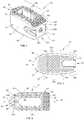
- top and bottom surfaces 22 , 24 and opposed side surfaces 26 , 28may include the same or different surface roughness's (i.e., the surface roughness of top surface 22 may be different than the surface roughness of bottom surface 24 ), or top and bottom surfaces 22 , 24 and opposed side surfaces 26 , 28 may not include a surface roughness; rather, top and bottom surfaces 22 , 24 and opposed side surfaces 26 , 28 may be smooth. In embodiments top and bottom surfaces 22 , 24 and opposed side surfaces 26 , 28 may include any combination of surface roughness or smooth surface.
- body portion 12includes a plurality of orifices 44 and 46 defined through top and bottom surfaces 22 , 24 and opposed side surfaces 26 , 28 , respectively, configured to promote bone ingrowth.
Landscapes
- Health & Medical Sciences (AREA)
- Engineering & Computer Science (AREA)
- Biomedical Technology (AREA)
- Orthopedic Medicine & Surgery (AREA)
- Neurology (AREA)
- Heart & Thoracic Surgery (AREA)
- Oral & Maxillofacial Surgery (AREA)
- Transplantation (AREA)
- Cardiology (AREA)
- Vascular Medicine (AREA)
- Life Sciences & Earth Sciences (AREA)
- Animal Behavior & Ethology (AREA)
- General Health & Medical Sciences (AREA)
- Public Health (AREA)
- Veterinary Medicine (AREA)
- Prostheses (AREA)
Abstract
Description
Claims (6)
Priority Applications (2)
| Application Number | Priority Date | Filing Date | Title |
|---|---|---|---|
| US16/039,701US10849764B2 (en) | 2015-01-27 | 2018-07-19 | Interbody spacer |
| US17/084,074US11382763B2 (en) | 2015-01-27 | 2020-10-29 | Interbody spacer |
Applications Claiming Priority (5)
| Application Number | Priority Date | Filing Date | Title |
|---|---|---|---|
| US201562108197P | 2015-01-27 | 2015-01-27 | |
| US201562196371P | 2015-07-24 | 2015-07-24 | |
| US201562240662P | 2015-10-13 | 2015-10-13 | |
| US15/007,879US10028841B2 (en) | 2015-01-27 | 2016-01-27 | Interbody spacer |
| US16/039,701US10849764B2 (en) | 2015-01-27 | 2018-07-19 | Interbody spacer |
Related Parent Applications (1)
| Application Number | Title | Priority Date | Filing Date |
|---|---|---|---|
| US15/007,879ContinuationUS10028841B2 (en) | 2015-01-27 | 2016-01-27 | Interbody spacer |
Related Child Applications (1)
| Application Number | Title | Priority Date | Filing Date |
|---|---|---|---|
| US17/084,074ContinuationUS11382763B2 (en) | 2015-01-27 | 2020-10-29 | Interbody spacer |
Publications (2)
| Publication Number | Publication Date |
|---|---|
| US20180325692A1 US20180325692A1 (en) | 2018-11-15 |
| US10849764B2true US10849764B2 (en) | 2020-12-01 |
Family
ID=56433031
Family Applications (3)
| Application Number | Title | Priority Date | Filing Date |
|---|---|---|---|
| US15/007,879ActiveUS10028841B2 (en) | 2015-01-27 | 2016-01-27 | Interbody spacer |
| US16/039,701ActiveUS10849764B2 (en) | 2015-01-27 | 2018-07-19 | Interbody spacer |
| US17/084,074Active2036-04-13US11382763B2 (en) | 2015-01-27 | 2020-10-29 | Interbody spacer |
Family Applications Before (1)
| Application Number | Title | Priority Date | Filing Date |
|---|---|---|---|
| US15/007,879ActiveUS10028841B2 (en) | 2015-01-27 | 2016-01-27 | Interbody spacer |
Family Applications After (1)
| Application Number | Title | Priority Date | Filing Date |
|---|---|---|---|
| US17/084,074Active2036-04-13US11382763B2 (en) | 2015-01-27 | 2020-10-29 | Interbody spacer |
Country Status (1)
| Country | Link |
|---|---|
| US (3) | US10028841B2 (en) |
Cited By (3)
| Publication number | Priority date | Publication date | Assignee | Title |
|---|---|---|---|---|
| US11058550B2 (en) | 2019-10-04 | 2021-07-13 | Pain TEQ, LLC | Allograft implant for fusing a sacroiliac joint |
| US11083511B2 (en) | 2013-03-15 | 2021-08-10 | Orthocision Inc. | Method and implant system for sacroiliac joint fixation and fusion |
| US11382763B2 (en)* | 2015-01-27 | 2022-07-12 | K2M, Inc. | Interbody spacer |
Families Citing this family (47)
| Publication number | Priority date | Publication date | Assignee | Title |
|---|---|---|---|---|
| US9220547B2 (en) | 2009-03-27 | 2015-12-29 | Spinal Elements, Inc. | Flanged interbody fusion device |
| US20160213405A1 (en)* | 2015-01-27 | 2016-07-28 | K2M, Inc. | Vertebral plate systems and methods of use |
| US20180338838A1 (en)* | 2016-02-03 | 2018-11-29 | Globus Medical, Inc. | Intervertebral Spinal Implants, Associated Instruments, And Methods Thereof |
| US10292825B2 (en)* | 2016-06-27 | 2019-05-21 | Globus Medical, Inc. | Intervertebral spacer with chamfered edges |
| US10292834B2 (en)* | 2016-06-27 | 2019-05-21 | Globus Medical, Inc. | Intervertebral spacer with chamfered edges |
| WO2018112050A2 (en)* | 2016-12-13 | 2018-06-21 | Aurora Spine, Inc. | Body density scan result-matched orthopedic implants and methods of use |
| US20210186710A1 (en)* | 2016-12-13 | 2021-06-24 | Aurora Spine, Inc. | Bone density scan result-matched orthopedic implants and methods of use |
| US20220160519A1 (en)* | 2016-12-13 | 2022-05-26 | Aurora Spine, Inc. | Bone density scan result-matched orthopedic implants and methods of use |
| US10624760B2 (en)* | 2017-05-22 | 2020-04-21 | Warsaw Orthopedic, Inc. | Spinal implant system and method |
| US10987142B2 (en) | 2017-08-04 | 2021-04-27 | K2M, Inc. | Pelvic wedge |
| WO2019051260A1 (en) | 2017-09-08 | 2019-03-14 | Pioneer Surgical Technology, Inc. | Intervertebral implants, instruments, and methods |
| US11039933B2 (en) | 2017-12-15 | 2021-06-22 | Innovasis, Inc. | Interbody spinal fusion implant with support struts |
| CN108056845A (en)* | 2017-12-15 | 2018-05-22 | 深圳清华大学研究院 | A kind of dypass lumbar intervertebral fusion device |
| US20210077267A1 (en) | 2018-02-26 | 2021-03-18 | K2M, Inc. | Spinal Implants With Custom Density And 3-D Printing Of Spinal Implants |
| USD870888S1 (en) | 2018-03-02 | 2019-12-24 | Restor3D, Inc. | Accordion airway stent |
| USD871577S1 (en) | 2018-03-02 | 2019-12-31 | Restor3D, Inc. | Studded airway stent |
| USD870890S1 (en) | 2018-03-02 | 2019-12-24 | Restor3D, Inc. | Spiral airway stent |
| USD870889S1 (en) | 2018-03-02 | 2019-12-24 | Restor3D, Inc. | Cutout airway stent |
| US10183442B1 (en) | 2018-03-02 | 2019-01-22 | Additive Device, Inc. | Medical devices and methods for producing the same |
| US10531962B2 (en)* | 2018-05-08 | 2020-01-14 | Globus Medical, Inc. | Intervertebral spinal implant |
| US11090094B2 (en) | 2018-06-01 | 2021-08-17 | Ehsan JAZINI | System and method for facilitating osteotomy of the pelvic |
| AU2019342137A1 (en) | 2018-09-20 | 2021-03-25 | Spinal Elements, Inc. | Spinal implant device |
| WO2020072469A1 (en) | 2018-10-01 | 2020-04-09 | K2M, Inc. | Graft scaffold |
| US11185423B2 (en)* | 2019-01-09 | 2021-11-30 | Osseus Fusion Systems | Highly radiographically opaque metal based interbody |
| US11298244B2 (en) | 2019-01-31 | 2022-04-12 | K2M, Inc. | Interbody implants and instrumentation |
| US10889053B1 (en) | 2019-03-25 | 2021-01-12 | Restor3D, Inc. | Custom surgical devices and method for manufacturing the same |
| US11857436B1 (en)* | 2019-07-31 | 2024-01-02 | Zavation Medical Products, Llc | Porous spinal implant |
| US11051953B2 (en)* | 2019-07-31 | 2021-07-06 | Zavation Medical Products, Llc | Porous spinal implant |
| USD930160S1 (en)* | 2019-09-11 | 2021-09-07 | L&K Biomed Co., Ltd. | End plate for a spinal fusion cage |
| USD929594S1 (en)* | 2019-09-11 | 2021-08-31 | L&K Biomed Co., Ltd. | End plate for a spinal fusion cage |
| US11534307B2 (en) | 2019-09-16 | 2022-12-27 | K2M, Inc. | 3D printed cervical standalone implant |
| USD950060S1 (en)* | 2019-12-24 | 2022-04-26 | PrinterPrezz, Inc. | Posterior lumbar interbody fusion device |
| USD920515S1 (en) | 2020-01-08 | 2021-05-25 | Restor3D, Inc. | Spinal implant |
| US10772732B1 (en) | 2020-01-08 | 2020-09-15 | Restor3D, Inc. | Sheet based triply periodic minimal surface implants for promoting osseointegration and methods for producing same |
| USD920516S1 (en) | 2020-01-08 | 2021-05-25 | Restor3D, Inc. | Osteotomy wedge |
| USD920517S1 (en) | 2020-01-08 | 2021-05-25 | Restor3D, Inc. | Osteotomy wedge |
| US11166825B1 (en)* | 2020-07-01 | 2021-11-09 | Warsaw Orthopedic, Inc. | Spinal implant |
| US20230380983A1 (en) | 2020-10-14 | 2023-11-30 | K2M, Inc. | Spinal Interbody Implants |
| US11911284B2 (en) | 2020-11-19 | 2024-02-27 | Spinal Elements, Inc. | Curved expandable interbody devices and deployment tools |
| WO2022133456A1 (en) | 2020-12-17 | 2022-06-23 | Spinal Elements, Inc. | Spinal implant device |
| TWI779675B (en) | 2021-06-18 | 2022-10-01 | 國立臺灣大學 | Intervertebral fusion device |
| US11850144B1 (en) | 2022-09-28 | 2023-12-26 | Restor3D, Inc. | Ligament docking implants and processes for making and using same |
| US11806028B1 (en) | 2022-10-04 | 2023-11-07 | Restor3D, Inc. | Surgical guides and processes for producing and using the same |
| USD1051384S1 (en) | 2023-03-24 | 2024-11-12 | Restor3D, Inc. | Bone fixation pin |
| USD1053353S1 (en) | 2023-03-24 | 2024-12-03 | Restor3D, Inc. | Orthopedic screw |
| USD1052732S1 (en) | 2023-05-25 | 2024-11-26 | Restor3D, Inc. | Subtalar wedge |
| US11960266B1 (en) | 2023-08-23 | 2024-04-16 | Restor3D, Inc. | Patient-specific medical devices and additive manufacturing processes for producing the same |
Citations (164)
| Publication number | Priority date | Publication date | Assignee | Title |
|---|---|---|---|---|
| US2375116A (en)* | 1943-06-09 | 1945-05-01 | John A Larkin | Riveted construction |
| WO1990000037A1 (en) | 1988-06-28 | 1990-01-11 | Michelson Gary K | Artificial spinal fusion implants |
| US5192327A (en) | 1991-03-22 | 1993-03-09 | Brantigan John W | Surgical prosthetic implant for vertebrae |
| WO1994019174A1 (en) | 1993-02-19 | 1994-09-01 | Eos Gmbh Electro Optical Systems | Process for producing a three-dimensional object |
| WO1995010248A1 (en) | 1993-10-12 | 1995-04-20 | Danek Medical, Inc. | Anterior interbody fusion device |
| WO1995032673A1 (en) | 1994-05-27 | 1995-12-07 | Michelson Gary K | Apparatus and method, delivery of electrical current |
| WO1996008360A1 (en) | 1994-09-16 | 1996-03-21 | Eos Gmbh Electro Optical Systems | Process for producing a three-dimensional object |
| US5534031A (en) | 1992-01-28 | 1996-07-09 | Asahi Kogaku Kogyo Kabushiki Kaisha | Prosthesis for spanning a space formed upon removal of an intervertebral disk |
| WO1996028117A1 (en) | 1995-03-13 | 1996-09-19 | Board Of Regents, The University Of Texas System | Biodegradable implant for fracture nonunions |
| WO1996040019A1 (en) | 1995-06-07 | 1996-12-19 | Michelson Gary K | Frusto-conical interbody spinal fusion implants |
| WO1996040015A1 (en) | 1995-06-07 | 1996-12-19 | Michelson Gary K | Lordotic interbody spinal fusion implants |
| US5595703A (en) | 1994-03-10 | 1997-01-21 | Materialise, Naamloze Vennootschap | Method for supporting an object made by means of stereolithography or another rapid prototype production method |
| US5634926A (en) | 1995-04-25 | 1997-06-03 | Jobe; Richard P. | Surgical bone fixation apparatus |
| WO1997034546A1 (en) | 1996-03-19 | 1997-09-25 | Axel Kirsch | Process for producing a bone substitute material |
| US5702449A (en) | 1995-06-07 | 1997-12-30 | Danek Medical, Inc. | Reinforced porous spinal implants |
| US5733286A (en) | 1997-02-12 | 1998-03-31 | Third Millennium Engineering, Llc | Rod securing polyaxial locking screw and coupling element assembly |
| US5768134A (en) | 1994-04-19 | 1998-06-16 | Materialise, Naamloze Vennootschap | Method for making a perfected medical model on the basis of digital image information of a part of the body |
| US5786134A (en) | 1997-05-15 | 1998-07-28 | Eastman Kodak Company | Motion picture print film |
| US5943235A (en) | 1995-09-27 | 1999-08-24 | 3D Systems, Inc. | Rapid prototyping system and method with support region data processing |
| US5968098A (en) | 1996-10-22 | 1999-10-19 | Surgical Dynamics, Inc. | Apparatus for fusing adjacent bone structures |
| US6010502A (en) | 1995-12-19 | 2000-01-04 | Spine-Tech, Inc. | Method and apparatus for conjoining bone bodies |
| US6039762A (en) | 1995-06-07 | 2000-03-21 | Sdgi Holdings, Inc. | Reinforced bone graft substitutes |
| WO2000025707A1 (en) | 1998-10-30 | 2000-05-11 | Michelson Gary K | Self-broaching, rotatable, push-in interbody fusion implant and method for deployment thereof |
| WO2000040177A1 (en) | 1999-01-05 | 2000-07-13 | Lifenet | Composite bone graft, method of making and using same |
| US6129730A (en) | 1999-02-10 | 2000-10-10 | Depuy Acromed, Inc. | Bi-fed offset pitch bone screw |
| US6143033A (en) | 1998-01-30 | 2000-11-07 | Synthes (Usa) | Allogenic intervertebral implant |
| WO2000066045A1 (en) | 1999-05-05 | 2000-11-09 | Michelson Gary K | Spinal fusion implants with opposed locking screws |
| US6245108B1 (en) | 1999-02-25 | 2001-06-12 | Spineco | Spinal fusion implant |
| US20010047208A1 (en) | 1999-12-08 | 2001-11-29 | Michelson Gary K. | Spinal implant surface configuration |
| WO2002002151A2 (en) | 2000-07-01 | 2002-01-10 | Bagby George W | Self-aligning and tapping bone joining implant |
| US6342055B1 (en) | 1999-04-29 | 2002-01-29 | Theken Surgical Llc | Bone fixation system |
| WO2002030337A2 (en) | 2000-10-11 | 2002-04-18 | Mason Michael D | Graftless spinal fusion device |
| US6391058B1 (en) | 1989-07-06 | 2002-05-21 | Sulzer Spine-Tech Inc. | Threaded spinal implant with convex trailing surface |
| US6409765B1 (en) | 1997-06-03 | 2002-06-25 | Sdgi Holdings, Inc. | Open intervertebral spacer |
| US6432107B1 (en) | 2000-01-15 | 2002-08-13 | Bret A. Ferree | Enhanced surface area spinal fusion devices |
| US20020120334A1 (en) | 1997-04-25 | 2002-08-29 | Yves Crozet | Intersomatic implants in two parts |
| US20020128714A1 (en) | 1999-06-04 | 2002-09-12 | Mark Manasas | Orthopedic implant and method of making metal articles |
| US6454811B1 (en) | 1998-10-12 | 2002-09-24 | Massachusetts Institute Of Technology | Composites for tissue regeneration and methods of manufacture thereof |
| WO2002080820A1 (en) | 2001-02-20 | 2002-10-17 | Howmedica Osteonics Corp. | Apparatus for fusing adjacent bone structures |
| US6520996B1 (en) | 1999-06-04 | 2003-02-18 | Depuy Acromed, Incorporated | Orthopedic implant |
| US6530956B1 (en) | 1998-09-10 | 2003-03-11 | Kevin A. Mansmann | Resorbable scaffolds to promote cartilage regeneration |
| US6530955B2 (en) | 1999-06-08 | 2003-03-11 | Osteotech, Inc. | Ramp-shaped intervertebral implant |
| US20030135276A1 (en) | 2002-01-17 | 2003-07-17 | Concept Matrix, Llc | Vertebral defect device |
| US20040034352A1 (en) | 2002-08-16 | 2004-02-19 | Needham Dusty Anna | Systems, instrumentation and techniques for retaining fasteners relative to a bone plate |
| US6716247B2 (en) | 2000-02-04 | 2004-04-06 | Gary K. Michelson | Expandable push-in interbody spinal fusion implant |
| US6730127B2 (en) | 2000-07-10 | 2004-05-04 | Gary K. Michelson | Flanged interbody spinal fusion implants |
| US6758849B1 (en) | 1995-02-17 | 2004-07-06 | Sdgi Holdings, Inc. | Interbody spinal fusion implants |
| EP1464307A1 (en) | 2003-03-31 | 2004-10-06 | DePuy Spine, Inc. | Intervertebral fusion implant |
| US20040243237A1 (en) | 2001-08-11 | 2004-12-02 | Paul Unwin | Surgical implant |
| US20040249471A1 (en) | 2003-06-05 | 2004-12-09 | Bindseil James J. | Fusion implant and method of making same |
| US20050010226A1 (en) | 2003-05-30 | 2005-01-13 | Grady Mark P. | Bone plate |
| US20050021151A1 (en) | 2001-05-29 | 2005-01-27 | Klaus Landis | Bone implant |
| US6855167B2 (en)* | 2001-12-05 | 2005-02-15 | Osteotech, Inc. | Spinal intervertebral implant, interconnections for such implant and processes for making |
| US20050055099A1 (en) | 2003-09-09 | 2005-03-10 | Ku David N. | Flexible spinal disc |
| US20050112397A1 (en) | 2003-07-24 | 2005-05-26 | Rolfe Jonathan L. | Assembled non-random foams |
| US20050137597A1 (en) | 2003-12-22 | 2005-06-23 | Life Spine | Dynamic cervical plates and cervical plate constructs |
| US20050149192A1 (en) | 2003-11-20 | 2005-07-07 | St. Francis Medical Technologies, Inc. | Intervertebral body fusion cage with keels and implantation method |
| US20050165400A1 (en) | 2004-01-26 | 2005-07-28 | Fernandez Alberto A. | Variable angle locked bone fixation system |
| US20050177238A1 (en) | 2001-05-01 | 2005-08-11 | Khandkar Ashok C. | Radiolucent bone graft |
| US20050246021A1 (en) | 2004-04-29 | 2005-11-03 | Ringeisen Timothy A | Compressed porous materials suitable for implant |
| US7018416B2 (en) | 2000-07-06 | 2006-03-28 | Zimmer Spine, Inc. | Bone implants and methods |
| WO2006101837A2 (en) | 2005-03-17 | 2006-09-28 | Spinal Elements, Inc. | Flanged interbody fusion device |
| US20060247772A1 (en) | 2005-04-29 | 2006-11-02 | Mckay William F | Synthetic loadbearing collagen-mineral composites useful for spinal implants, and methods of manufacture |
| US20060264946A1 (en) | 2003-03-26 | 2006-11-23 | Young Robert A | Locking bone plate |
| US7238206B2 (en) | 2003-10-17 | 2007-07-03 | Co-Ligne Ag | Fusion implant |
| US20070233272A1 (en) | 1999-02-23 | 2007-10-04 | Boyce Todd M | Shaped load-bearing osteoimplant and methods of making same |
| US20070260324A1 (en) | 2006-05-05 | 2007-11-08 | Joshi Ashok V | Fully or Partially Bioresorbable Orthopedic Implant |
| US20070270965A1 (en) | 2006-04-28 | 2007-11-22 | Joe Ferguson | Orthopedic support locating or centering feature and method |
| US20070270812A1 (en) | 2006-04-14 | 2007-11-22 | Sdgi Holdings, Inc. | Fixation plate and method of use |
| US20080097444A1 (en) | 2006-07-21 | 2008-04-24 | Merlot Orthopedix | Apparatus and method for body tissue fixation |
| US20080154379A1 (en) | 2006-12-22 | 2008-06-26 | Musculoskeletal Transplant Foundation | Interbody fusion hybrid graft |
| US20080312743A1 (en) | 2007-06-15 | 2008-12-18 | Thierry Vila | Nucleus Prostheses |
| US20090018584A1 (en) | 2007-01-29 | 2009-01-15 | Polaris Biotechnology, Inc. | Vertebra attachment method and system |
| US20090048675A1 (en) | 2007-04-25 | 2009-02-19 | Bhatnagar Mohit K | Spinal Fusion Implants with Selectively Applied Bone Growth Promoting Agent |
| US20090054930A1 (en) | 2007-08-20 | 2009-02-26 | Kamran Aflatoon | Anterior cervical staple |
| US7509183B2 (en) | 2003-04-23 | 2009-03-24 | The Regents Of The University Of Michigan | Integrated global layout and local microstructure topology optimization approach for spinal cage design and fabrication |
| US20090093881A1 (en) | 2007-10-05 | 2009-04-09 | Washington State University | Modified metal materials, surface modifications to improve cell interactions and antimicrobial properties, and methods for modifying metal surface properties |
| WO2009068021A1 (en) | 2007-11-27 | 2009-06-04 | Kloss, Henning | Intervertebral implant |
| US20090270986A1 (en) | 2005-12-08 | 2009-10-29 | Fbcdevice Aps | Disc Implant |
| US20090291308A1 (en) | 2008-05-21 | 2009-11-26 | Eos Gmbh Electro Optical Systems | Method and device of layerwise manufacturing a three-dimensional object of a powdery material |
| DE102008024288A1 (en) | 2008-05-20 | 2009-12-03 | Eos Gmbh Electro Optical Systems | Preparing a three-dimensional object from a powder, comprising polymer or copolymer containing an aromatic group that non-linearly links to the main chain, comprises selective sintering of the powder by electromagnetic radiation |
| US20090295042A1 (en) | 2008-05-20 | 2009-12-03 | Eos Gmbh Electro Optical Systems | Selective sintering of structurally modified polymers |
| DE102008024281A1 (en) | 2008-05-20 | 2009-12-03 | Eos Gmbh Electro Optical Systems | Producing a three-dimensional object by selectively sintering a polymer powder comprises using a polymer that has a branching group in the main chain, has a modified terminal group and/or has a bulky group in the main chain |
| US20100004747A1 (en) | 2008-07-07 | 2010-01-07 | Jin-Fu Lin | Trans-Vertebral and Intra-Vertebral Plate and Fusion Cage Device for Spinal Interbody Fusion and Method of Operation |
| US7645301B2 (en) | 2006-01-13 | 2010-01-12 | Zimmer Spine, Inc. | Devices and methods for disc replacement |
| EP1905391B1 (en) | 2006-09-27 | 2010-01-13 | K2M, Inc. | Spinal interbody spacer |
| US7665979B2 (en) | 2002-08-02 | 2010-02-23 | Eos Gmbh Electro Optical Systems | Device and method for the production of three-dimensional objects by means of generative production method |
| US20100100131A1 (en) | 2008-10-21 | 2010-04-22 | K2M, Inc. | Spinal buttress plate |
| US20100137990A1 (en) | 2007-02-20 | 2010-06-03 | National University Of Ireland, Galway | Porous Substrates for Implantation |
| US20100228369A1 (en) | 2007-10-10 | 2010-09-09 | Materialise Nv | Method and apparatus for automatic support generation for an object made by means of a rapid prototype production method |
| USD623749S1 (en) | 2009-10-23 | 2010-09-14 | Horton Kenneth L | Cervical spinal implant |
| US20100234966A1 (en) | 2006-05-24 | 2010-09-16 | Orthogem Limited | Bone repair or augmentation device |
| US20100268339A1 (en)* | 2007-07-10 | 2010-10-21 | Malinin Theodore I | Intervertebral Spinal Implant and Method of Making the Same |
| WO2011030017A1 (en) | 2009-09-09 | 2011-03-17 | Obl (Société Anonyme) | Porous structure having a controlled pattern, repeated in space, for producing surgical implants |
| US7909872B2 (en) | 2005-06-03 | 2011-03-22 | Zipnick Richard I | Minimally invasive apparatus to manipulate and revitalize spinal column disc |
| US20110144752A1 (en) | 2008-08-14 | 2011-06-16 | Defelice Scott F | Customized implants for bone replacement |
| US20110165340A1 (en) | 2010-01-05 | 2011-07-07 | Eos Gmbh Electro Optical Systems | Device for generatively manufacturing a three-dimensional object with continuous heat supply |
| US20110168091A1 (en) | 2010-01-05 | 2011-07-14 | Eos Gmbh Electro Optical Systems | Device of Generatively Manufacturing Three-Dimensional Objects with Insulated Building Field |
| US20110190888A1 (en) | 2010-02-01 | 2011-08-04 | Bertele Theodore P | Composite Interbody Device And Method of Manufacture |
| US20110190904A1 (en) | 2009-12-30 | 2011-08-04 | Beat Lechmann | Integrated multi-material implants and methods of manufacture |
| US20110301709A1 (en) | 2010-06-03 | 2011-12-08 | Kilian Kraus | Intervertebral implant |
| US20120046750A1 (en) | 2009-03-05 | 2012-02-23 | Dsm Ip Assets B.V. | Spinal fusion cage |
| EP2457538A1 (en) | 2009-07-22 | 2012-05-30 | Next21 K.K. | Artificial bone constructing unit and artificial bone constructing system |
| US20120143334A1 (en) | 1999-02-23 | 2012-06-07 | Warsaw Orthopedic, Inc. | Shaped load-bearing osteoimplant and methods of making the same |
| US20120158062A1 (en) | 2010-12-17 | 2012-06-21 | K2M, Inc. | Interbody spacer |
| US20120179261A1 (en) | 2011-01-07 | 2012-07-12 | K2M, Inc. | Interbody spacer |
| USD664252S1 (en) | 2011-01-27 | 2012-07-24 | Advanced Medical Technologies Ag | Wave oblique |
| US20120191189A1 (en) | 2011-01-20 | 2012-07-26 | Huang meng-feng | Spinal implant with padded bone engaging projections |
| US20120191188A1 (en)* | 2011-01-20 | 2012-07-26 | Huang meng-feng | Spinal implant with bone engaging projections |
| US20120203229A1 (en) | 2010-08-13 | 2012-08-09 | Andreas Appenzeller | Bone Stabilization Device |
| US8275594B2 (en) | 2006-10-30 | 2012-09-25 | The Regents Of The University Of Michigan | Engineered scaffolds for intervertebral disc repair and regeneration and for articulating joint repair and regeneration |
| US8287541B2 (en)* | 2005-05-18 | 2012-10-16 | Sonoma Orthopedic Products, Inc. | Fracture fixation device, tools and methods |
| US20120303128A1 (en) | 2005-05-06 | 2012-11-29 | Titan Spine, Llc | Spinal implant and integration plate for optimizing vertebral endplate contact load-bearing edges |
| US20120310364A1 (en) | 2011-05-06 | 2012-12-06 | Zimmer, Inc. | Patient-specific manufacturing of porous metal prostheses |
| US20120316650A1 (en) | 2005-05-06 | 2012-12-13 | Titan Spine, Llc | Implants having three distinct surfaces |
| WO2013017647A1 (en) | 2011-08-02 | 2013-02-07 | Materialise Nv | Additive manufacturing of openings with reduced dimensions |
| US20130046345A1 (en) | 2010-08-20 | 2013-02-21 | K2M, Inc. | Spinal fixation system |
| US20130110243A1 (en) | 2011-11-01 | 2013-05-02 | Titan Spine Llc | Microstructured implant surfaces |
| US20130116793A1 (en)* | 2010-07-23 | 2013-05-09 | Privelop-Spine Ag | Surgical implant |
| US8439977B2 (en) | 2008-10-08 | 2013-05-14 | K2M, Inc. | Spinal interbody spacer |
| US8449585B2 (en) | 2009-11-05 | 2013-05-28 | K2M, Inc. | Semi-constrained bone screw |
| US8449463B2 (en) | 2010-10-08 | 2013-05-28 | K2M, Inc. | Lateral access system and method of use |
| US20130150893A1 (en) | 2005-07-29 | 2013-06-13 | X-Spine Systems, Inc. | Capless multiaxial screw and spinal fixation assembly and method |
| US20130171019A1 (en) | 2010-09-03 | 2013-07-04 | Eos Gmbh Electro Optical Systems | Method of manufacturing a three-dimensional object having an internal structure |
| US20130184765A1 (en) | 2012-01-16 | 2013-07-18 | Carbofix Orthopedics Ltd. | Multi-axial bone plate fixation |
| WO2013155500A1 (en) | 2012-04-13 | 2013-10-17 | Conformis, Inc. | Devices and methods for additive manufacturing of implant components |
| US20130273131A1 (en) | 2009-04-08 | 2013-10-17 | Arkema France, SA | Method of Manufacturing a Three-Dimensional Object by Use of Synthetic Powder Having Anti-Microbial Properties, and Synthetic Powder Having Anti-Microbial Properties for Such a Method |
| WO2013156545A1 (en) | 2012-04-18 | 2013-10-24 | Materialise N.V. | Orthopedic bone fixation systems and methods |
| US8585761B2 (en) | 2008-03-28 | 2013-11-19 | K2M, Inc. | Expandable cage with locking device |
| US8590157B2 (en) | 2005-01-25 | 2013-11-26 | Layerwise N.V. | Procedure for design and production of implant-based frameworks for complex dental prostheses |
| US8597359B2 (en) | 2006-09-14 | 2013-12-03 | Life Spine, Inc. | Cervical and lumbar spinal interbody devices |
| CN103445883A (en) | 2012-06-04 | 2013-12-18 | 合硕生技股份有限公司 | Medical implant with hollowed-out net frame |
| US8669043B2 (en)* | 1998-11-13 | 2014-03-11 | Rti Surgical, Inc. | Cyclic implant perfusion, cleaning and passivation process and implant produced thereby |
| US8673011B2 (en) | 2008-03-28 | 2014-03-18 | K2M, Inc. | Expandable cage |
| US20140088716A1 (en) | 2012-09-21 | 2014-03-27 | Zimmer, Inc. | Variable density implant and method |
| US20140107786A1 (en) | 2012-10-11 | 2014-04-17 | Rhausler, Inc. | Fusion cage implant with lattice structure |
| US20140107785A1 (en) | 2012-10-11 | 2014-04-17 | Rhausler, Inc. | Bone plate and fusion cage interface |
| US20140172111A1 (en) | 2012-09-20 | 2014-06-19 | Conformis, Inc. | Solid freeform fabrication of implant components |
| WO2014096294A1 (en) | 2012-12-21 | 2014-06-26 | Materialise N.V. | Method for manufacturing objects by selective sintering |
| US8784721B2 (en) | 2007-11-27 | 2014-07-22 | Eos Gmbh Electro Optical Systems | Method of manufacturing three-dimensional objects by laser sintering |
| US8814919B2 (en) | 2007-10-23 | 2014-08-26 | K2M, Inc. | Posterior pedicle screw having a taper lock |
| US20140277491A1 (en) | 2013-03-15 | 2014-09-18 | Blackstone Medical, Inc. | Composite spinal interbody device and method |
| US8843229B2 (en) | 2012-07-20 | 2014-09-23 | Biomet Manufacturing, Llc | Metallic structures having porous regions from imaged bone at pre-defined anatomic locations |
| US8870957B2 (en) | 2009-03-04 | 2014-10-28 | Amendia, Inc. | Implant for mammalian bony segment stabilization |
| US20150018956A1 (en) | 2012-06-21 | 2015-01-15 | Renovis Surgical, Inc. | Surgical implant devices incorporating porous surfaces |
| US20150045924A1 (en) | 2013-08-12 | 2015-02-12 | Materialise Nv | Data processing |
| US8967990B2 (en) | 2006-05-18 | 2015-03-03 | Eos Gmbh Electro Optical Systems | Device and method for a layerwise manufacturing of a 3-dimensional object from a building material in powder form |
| US8999711B2 (en) | 2005-12-14 | 2015-04-07 | The Invention Science Fund I, Llc | Bone delivery device |
| US9011982B2 (en) | 2007-05-25 | 2015-04-21 | Eos Gmbh Electro Optical Systems | Method for a layer-wise manufacturing of a three-dimensional object |
| US20150134063A1 (en) | 2012-06-21 | 2015-05-14 | Renovis Surgical Technologies, Inc. | Surgical implant devices incorporating porous surfaces and a locking plate |
| US20150142158A1 (en) | 2012-07-06 | 2015-05-21 | Eos Gmbh Electro Optical Systems | Method and Device for Producing a Three-Dimensional Object in Layers |
| EP1772108B1 (en) | 2005-06-30 | 2015-11-11 | Kasios | Wedge for tibial or femoral osteotomy |
| US20160022431A1 (en) | 2014-07-28 | 2016-01-28 | Warsaw Orthopedic, Inc. | Spinal implant system and method |
| US9247970B2 (en)* | 2009-08-19 | 2016-02-02 | DePuy Synthes Products, Inc. | Method and apparatus for augmenting bone |
| US20160038301A1 (en) | 2014-08-08 | 2016-02-11 | Warsaw Orthopedic, Inc. | Spinal implant system and method |
| US20160058575A1 (en) | 2013-03-14 | 2016-03-03 | K2M, Inc. | Spinal fixation device |
| US9283078B2 (en) | 2012-09-21 | 2016-03-15 | Materialise N.V. | Patient-specific intraluminal implants |
| US20160199193A1 (en) | 2015-01-14 | 2016-07-14 | Stryker European Holdings I, Llc | Spinal implant with porous and solid surfaces |
| US20160213488A1 (en) | 2015-01-27 | 2016-07-28 | K2M, Inc. | Interbody spacer |
| US20160213485A1 (en) | 2015-01-27 | 2016-07-28 | K2M, Inc. | Interbody spacer |
| USD786434S1 (en) | 2015-12-04 | 2017-05-09 | ACES Ing.-GmbH | Spinal implant |
| US9700431B2 (en) | 2008-08-13 | 2017-07-11 | Smed-Ta/Td, Llc | Orthopaedic implant with porous structural member |
| US20190298542A1 (en) | 2010-07-23 | 2019-10-03 | Privelop-Spine Ag | Surgical implant |
| US20190328546A1 (en) | 2018-03-21 | 2019-10-31 | Life Spine, Inc. | Steerable TLIF Spine Implant, Installer, and Method of Installation |
Family Cites Families (1)
| Publication number | Priority date | Publication date | Assignee | Title |
|---|---|---|---|---|
| US11058550B2 (en)* | 2019-10-04 | 2021-07-13 | Pain TEQ, LLC | Allograft implant for fusing a sacroiliac joint |
- 2016
- 2016-01-27USUS15/007,879patent/US10028841B2/enactiveActive
- 2018
- 2018-07-19USUS16/039,701patent/US10849764B2/enactiveActive
- 2020
- 2020-10-29USUS17/084,074patent/US11382763B2/enactiveActive
Patent Citations (184)
| Publication number | Priority date | Publication date | Assignee | Title |
|---|---|---|---|---|
| US2375116A (en)* | 1943-06-09 | 1945-05-01 | John A Larkin | Riveted construction |
| WO1990000037A1 (en) | 1988-06-28 | 1990-01-11 | Michelson Gary K | Artificial spinal fusion implants |
| EP0425542B1 (en) | 1988-06-28 | 1995-03-01 | Karlin Technology, Inc. | Artificial spinal fusion implants |
| US5609635A (en) | 1988-06-28 | 1997-03-11 | Michelson; Gary K. | Lordotic interbody spinal fusion implants |
| US6391058B1 (en) | 1989-07-06 | 2002-05-21 | Sulzer Spine-Tech Inc. | Threaded spinal implant with convex trailing surface |
| US5192327A (en) | 1991-03-22 | 1993-03-09 | Brantigan John W | Surgical prosthetic implant for vertebrae |
| WO1994005235A1 (en) | 1991-03-22 | 1994-03-17 | Brantigan John W | Surgical prosthetic implant for vertebrae |
| US5534031A (en) | 1992-01-28 | 1996-07-09 | Asahi Kogaku Kogyo Kabushiki Kaisha | Prosthesis for spanning a space formed upon removal of an intervertebral disk |
| WO1994019174A1 (en) | 1993-02-19 | 1994-09-01 | Eos Gmbh Electro Optical Systems | Process for producing a three-dimensional object |
| WO1995010248A1 (en) | 1993-10-12 | 1995-04-20 | Danek Medical, Inc. | Anterior interbody fusion device |
| US5595703A (en) | 1994-03-10 | 1997-01-21 | Materialise, Naamloze Vennootschap | Method for supporting an object made by means of stereolithography or another rapid prototype production method |
| US5768134A (en) | 1994-04-19 | 1998-06-16 | Materialise, Naamloze Vennootschap | Method for making a perfected medical model on the basis of digital image information of a part of the body |
| US20040024400A1 (en) | 1994-05-27 | 2004-02-05 | Michelson Gary Karlin | Method for the delivery of electrical current to promote bone growth between adjacent bone masses |
| WO1995032673A1 (en) | 1994-05-27 | 1995-12-07 | Michelson Gary K | Apparatus and method, delivery of electrical current |
| WO1996008360A1 (en) | 1994-09-16 | 1996-03-21 | Eos Gmbh Electro Optical Systems | Process for producing a three-dimensional object |
| US6758849B1 (en) | 1995-02-17 | 2004-07-06 | Sdgi Holdings, Inc. | Interbody spinal fusion implants |
| WO1996028117A1 (en) | 1995-03-13 | 1996-09-19 | Board Of Regents, The University Of Texas System | Biodegradable implant for fracture nonunions |
| US5634926A (en) | 1995-04-25 | 1997-06-03 | Jobe; Richard P. | Surgical bone fixation apparatus |
| US6039762A (en) | 1995-06-07 | 2000-03-21 | Sdgi Holdings, Inc. | Reinforced bone graft substitutes |
| WO1996040015A1 (en) | 1995-06-07 | 1996-12-19 | Michelson Gary K | Lordotic interbody spinal fusion implants |
| US20030040798A1 (en) | 1995-06-07 | 2003-02-27 | Michelson Gary Karlin | Lordotic interbody spinal fusion implants |
| WO1996040019A1 (en) | 1995-06-07 | 1996-12-19 | Michelson Gary K | Frusto-conical interbody spinal fusion implants |
| US5702449A (en) | 1995-06-07 | 1997-12-30 | Danek Medical, Inc. | Reinforced porous spinal implants |
| US5943235A (en) | 1995-09-27 | 1999-08-24 | 3D Systems, Inc. | Rapid prototyping system and method with support region data processing |
| US6010502A (en) | 1995-12-19 | 2000-01-04 | Spine-Tech, Inc. | Method and apparatus for conjoining bone bodies |
| WO1997034546A1 (en) | 1996-03-19 | 1997-09-25 | Axel Kirsch | Process for producing a bone substitute material |
| US5968098A (en) | 1996-10-22 | 1999-10-19 | Surgical Dynamics, Inc. | Apparatus for fusing adjacent bone structures |
| US5733286A (en) | 1997-02-12 | 1998-03-31 | Third Millennium Engineering, Llc | Rod securing polyaxial locking screw and coupling element assembly |
| US20020120334A1 (en) | 1997-04-25 | 2002-08-29 | Yves Crozet | Intersomatic implants in two parts |
| US5786134A (en) | 1997-05-15 | 1998-07-28 | Eastman Kodak Company | Motion picture print film |
| US6409765B1 (en) | 1997-06-03 | 2002-06-25 | Sdgi Holdings, Inc. | Open intervertebral spacer |
| US6143033A (en) | 1998-01-30 | 2000-11-07 | Synthes (Usa) | Allogenic intervertebral implant |
| US6530956B1 (en) | 1998-09-10 | 2003-03-11 | Kevin A. Mansmann | Resorbable scaffolds to promote cartilage regeneration |
| US6454811B1 (en) | 1998-10-12 | 2002-09-24 | Massachusetts Institute Of Technology | Composites for tissue regeneration and methods of manufacture thereof |
| WO2000025707A1 (en) | 1998-10-30 | 2000-05-11 | Michelson Gary K | Self-broaching, rotatable, push-in interbody fusion implant and method for deployment thereof |
| US20010047207A1 (en) | 1998-10-30 | 2001-11-29 | Michelson Gary K. | Self-broaching, rotatable, push-in interbody spinal fusion implant and method for deployment thereof |
| US8669043B2 (en)* | 1998-11-13 | 2014-03-11 | Rti Surgical, Inc. | Cyclic implant perfusion, cleaning and passivation process and implant produced thereby |
| WO2000040177A1 (en) | 1999-01-05 | 2000-07-13 | Lifenet | Composite bone graft, method of making and using same |
| US6129730A (en) | 1999-02-10 | 2000-10-10 | Depuy Acromed, Inc. | Bi-fed offset pitch bone screw |
| US20120143334A1 (en) | 1999-02-23 | 2012-06-07 | Warsaw Orthopedic, Inc. | Shaped load-bearing osteoimplant and methods of making the same |
| US20070233272A1 (en) | 1999-02-23 | 2007-10-04 | Boyce Todd M | Shaped load-bearing osteoimplant and methods of making same |
| US6245108B1 (en) | 1999-02-25 | 2001-06-12 | Spineco | Spinal fusion implant |
| US6342055B1 (en) | 1999-04-29 | 2002-01-29 | Theken Surgical Llc | Bone fixation system |
| US8403986B2 (en) | 1999-05-05 | 2013-03-26 | Warsaw Orthopedic, Inc. | Push-in interbody spinal fusion implant with multi-lock for locking opposed screws and method for use thereof |
| WO2000066045A1 (en) | 1999-05-05 | 2000-11-09 | Michelson Gary K | Spinal fusion implants with opposed locking screws |
| US6520996B1 (en) | 1999-06-04 | 2003-02-18 | Depuy Acromed, Incorporated | Orthopedic implant |
| US20020128714A1 (en) | 1999-06-04 | 2002-09-12 | Mark Manasas | Orthopedic implant and method of making metal articles |
| US6530955B2 (en) | 1999-06-08 | 2003-03-11 | Osteotech, Inc. | Ramp-shaped intervertebral implant |
| US20010047208A1 (en) | 1999-12-08 | 2001-11-29 | Michelson Gary K. | Spinal implant surface configuration |
| US6432107B1 (en) | 2000-01-15 | 2002-08-13 | Bret A. Ferree | Enhanced surface area spinal fusion devices |
| US6716247B2 (en) | 2000-02-04 | 2004-04-06 | Gary K. Michelson | Expandable push-in interbody spinal fusion implant |
| WO2002002151A2 (en) | 2000-07-01 | 2002-01-10 | Bagby George W | Self-aligning and tapping bone joining implant |
| US7018416B2 (en) | 2000-07-06 | 2006-03-28 | Zimmer Spine, Inc. | Bone implants and methods |
| US6730127B2 (en) | 2000-07-10 | 2004-05-04 | Gary K. Michelson | Flanged interbody spinal fusion implants |
| WO2002030337A2 (en) | 2000-10-11 | 2002-04-18 | Mason Michael D | Graftless spinal fusion device |
| WO2002080820A1 (en) | 2001-02-20 | 2002-10-17 | Howmedica Osteonics Corp. | Apparatus for fusing adjacent bone structures |
| US20050177238A1 (en) | 2001-05-01 | 2005-08-11 | Khandkar Ashok C. | Radiolucent bone graft |
| US20050021151A1 (en) | 2001-05-29 | 2005-01-27 | Klaus Landis | Bone implant |
| US20040243237A1 (en) | 2001-08-11 | 2004-12-02 | Paul Unwin | Surgical implant |
| US6855167B2 (en)* | 2001-12-05 | 2005-02-15 | Osteotech, Inc. | Spinal intervertebral implant, interconnections for such implant and processes for making |
| US20030135276A1 (en) | 2002-01-17 | 2003-07-17 | Concept Matrix, Llc | Vertebral defect device |
| US7665979B2 (en) | 2002-08-02 | 2010-02-23 | Eos Gmbh Electro Optical Systems | Device and method for the production of three-dimensional objects by means of generative production method |
| US20040034352A1 (en) | 2002-08-16 | 2004-02-19 | Needham Dusty Anna | Systems, instrumentation and techniques for retaining fasteners relative to a bone plate |
| US20060264946A1 (en) | 2003-03-26 | 2006-11-23 | Young Robert A | Locking bone plate |
| EP1464307A1 (en) | 2003-03-31 | 2004-10-06 | DePuy Spine, Inc. | Intervertebral fusion implant |
| US7509183B2 (en) | 2003-04-23 | 2009-03-24 | The Regents Of The University Of Michigan | Integrated global layout and local microstructure topology optimization approach for spinal cage design and fabrication |
| US9931148B2 (en) | 2003-05-30 | 2018-04-03 | DePuy Synthes Products, Inc. | Bone plate |
| US20050010226A1 (en) | 2003-05-30 | 2005-01-13 | Grady Mark P. | Bone plate |
| US20040249471A1 (en) | 2003-06-05 | 2004-12-09 | Bindseil James J. | Fusion implant and method of making same |
| US20050112397A1 (en) | 2003-07-24 | 2005-05-26 | Rolfe Jonathan L. | Assembled non-random foams |
| US20050055099A1 (en) | 2003-09-09 | 2005-03-10 | Ku David N. | Flexible spinal disc |
| US7238206B2 (en) | 2003-10-17 | 2007-07-03 | Co-Ligne Ag | Fusion implant |
| US20050149192A1 (en) | 2003-11-20 | 2005-07-07 | St. Francis Medical Technologies, Inc. | Intervertebral body fusion cage with keels and implantation method |
| US20050137597A1 (en) | 2003-12-22 | 2005-06-23 | Life Spine | Dynamic cervical plates and cervical plate constructs |
| US20050165400A1 (en) | 2004-01-26 | 2005-07-28 | Fernandez Alberto A. | Variable angle locked bone fixation system |
| US20050246021A1 (en) | 2004-04-29 | 2005-11-03 | Ringeisen Timothy A | Compressed porous materials suitable for implant |
| US8590157B2 (en) | 2005-01-25 | 2013-11-26 | Layerwise N.V. | Procedure for design and production of implant-based frameworks for complex dental prostheses |
| US20060235403A1 (en) | 2005-03-17 | 2006-10-19 | Jason Blain | Flanged interbody fusion device with locking plate |
| WO2006101837A2 (en) | 2005-03-17 | 2006-09-28 | Spinal Elements, Inc. | Flanged interbody fusion device |
| US20060247772A1 (en) | 2005-04-29 | 2006-11-02 | Mckay William F | Synthetic loadbearing collagen-mineral composites useful for spinal implants, and methods of manufacture |
| US20120316650A1 (en) | 2005-05-06 | 2012-12-13 | Titan Spine, Llc | Implants having three distinct surfaces |
| US20120303128A1 (en) | 2005-05-06 | 2012-11-29 | Titan Spine, Llc | Spinal implant and integration plate for optimizing vertebral endplate contact load-bearing edges |
| US8287541B2 (en)* | 2005-05-18 | 2012-10-16 | Sonoma Orthopedic Products, Inc. | Fracture fixation device, tools and methods |
| US7909872B2 (en) | 2005-06-03 | 2011-03-22 | Zipnick Richard I | Minimally invasive apparatus to manipulate and revitalize spinal column disc |
| EP1772108B1 (en) | 2005-06-30 | 2015-11-11 | Kasios | Wedge for tibial or femoral osteotomy |
| US20130150893A1 (en) | 2005-07-29 | 2013-06-13 | X-Spine Systems, Inc. | Capless multiaxial screw and spinal fixation assembly and method |
| US20090270986A1 (en) | 2005-12-08 | 2009-10-29 | Fbcdevice Aps | Disc Implant |
| US8999711B2 (en) | 2005-12-14 | 2015-04-07 | The Invention Science Fund I, Llc | Bone delivery device |
| US7645301B2 (en) | 2006-01-13 | 2010-01-12 | Zimmer Spine, Inc. | Devices and methods for disc replacement |
| US20070270812A1 (en) | 2006-04-14 | 2007-11-22 | Sdgi Holdings, Inc. | Fixation plate and method of use |
| US7806911B2 (en) | 2006-04-14 | 2010-10-05 | Warsaw Orthopedic, Inc. | Fixation plate and method of use |
| US20070270965A1 (en) | 2006-04-28 | 2007-11-22 | Joe Ferguson | Orthopedic support locating or centering feature and method |
| US20070260324A1 (en) | 2006-05-05 | 2007-11-08 | Joshi Ashok V | Fully or Partially Bioresorbable Orthopedic Implant |
| US8967990B2 (en) | 2006-05-18 | 2015-03-03 | Eos Gmbh Electro Optical Systems | Device and method for a layerwise manufacturing of a 3-dimensional object from a building material in powder form |
| US20100234966A1 (en) | 2006-05-24 | 2010-09-16 | Orthogem Limited | Bone repair or augmentation device |
| US20080097444A1 (en) | 2006-07-21 | 2008-04-24 | Merlot Orthopedix | Apparatus and method for body tissue fixation |
| US8597359B2 (en) | 2006-09-14 | 2013-12-03 | Life Spine, Inc. | Cervical and lumbar spinal interbody devices |
| EP1905391B1 (en) | 2006-09-27 | 2010-01-13 | K2M, Inc. | Spinal interbody spacer |
| US8801791B2 (en) | 2006-09-27 | 2014-08-12 | K2M, Inc. | Spinal interbody spacer |
| US8275594B2 (en) | 2006-10-30 | 2012-09-25 | The Regents Of The University Of Michigan | Engineered scaffolds for intervertebral disc repair and regeneration and for articulating joint repair and regeneration |
| US20080154379A1 (en) | 2006-12-22 | 2008-06-26 | Musculoskeletal Transplant Foundation | Interbody fusion hybrid graft |
| US20090018584A1 (en) | 2007-01-29 | 2009-01-15 | Polaris Biotechnology, Inc. | Vertebra attachment method and system |
| US20100137990A1 (en) | 2007-02-20 | 2010-06-03 | National University Of Ireland, Galway | Porous Substrates for Implantation |
| US20090048675A1 (en) | 2007-04-25 | 2009-02-19 | Bhatnagar Mohit K | Spinal Fusion Implants with Selectively Applied Bone Growth Promoting Agent |
| US9011982B2 (en) | 2007-05-25 | 2015-04-21 | Eos Gmbh Electro Optical Systems | Method for a layer-wise manufacturing of a three-dimensional object |
| US20080312743A1 (en) | 2007-06-15 | 2008-12-18 | Thierry Vila | Nucleus Prostheses |
| US20100268339A1 (en)* | 2007-07-10 | 2010-10-21 | Malinin Theodore I | Intervertebral Spinal Implant and Method of Making the Same |
| US20090054930A1 (en) | 2007-08-20 | 2009-02-26 | Kamran Aflatoon | Anterior cervical staple |
| US20090093881A1 (en) | 2007-10-05 | 2009-04-09 | Washington State University | Modified metal materials, surface modifications to improve cell interactions and antimicrobial properties, and methods for modifying metal surface properties |
| US8903533B2 (en) | 2007-10-10 | 2014-12-02 | Materialise Nv | Method and apparatus for automatic support generation for an object made by means of a rapid prototype production method |
| US20100228369A1 (en) | 2007-10-10 | 2010-09-09 | Materialise Nv | Method and apparatus for automatic support generation for an object made by means of a rapid prototype production method |
| US8814919B2 (en) | 2007-10-23 | 2014-08-26 | K2M, Inc. | Posterior pedicle screw having a taper lock |
| WO2009068021A1 (en) | 2007-11-27 | 2009-06-04 | Kloss, Henning | Intervertebral implant |
| US8932356B2 (en) | 2007-11-27 | 2015-01-13 | Henning Kloss | Intervertebral implant |
| US8784721B2 (en) | 2007-11-27 | 2014-07-22 | Eos Gmbh Electro Optical Systems | Method of manufacturing three-dimensional objects by laser sintering |
| US8673011B2 (en) | 2008-03-28 | 2014-03-18 | K2M, Inc. | Expandable cage |
| US8585761B2 (en) | 2008-03-28 | 2013-11-19 | K2M, Inc. | Expandable cage with locking device |
| US20090295042A1 (en) | 2008-05-20 | 2009-12-03 | Eos Gmbh Electro Optical Systems | Selective sintering of structurally modified polymers |
| EP2145913A1 (en) | 2008-05-20 | 2010-01-20 | EOS GmbH Electro Optical Systems | Selective sintering of structurally modified polymers |
| DE102008024281A1 (en) | 2008-05-20 | 2009-12-03 | Eos Gmbh Electro Optical Systems | Producing a three-dimensional object by selectively sintering a polymer powder comprises using a polymer that has a branching group in the main chain, has a modified terminal group and/or has a bulky group in the main chain |
| DE102008024288A1 (en) | 2008-05-20 | 2009-12-03 | Eos Gmbh Electro Optical Systems | Preparing a three-dimensional object from a powder, comprising polymer or copolymer containing an aromatic group that non-linearly links to the main chain, comprises selective sintering of the powder by electromagnetic radiation |
| US20090291308A1 (en) | 2008-05-21 | 2009-11-26 | Eos Gmbh Electro Optical Systems | Method and device of layerwise manufacturing a three-dimensional object of a powdery material |
| US20100004747A1 (en) | 2008-07-07 | 2010-01-07 | Jin-Fu Lin | Trans-Vertebral and Intra-Vertebral Plate and Fusion Cage Device for Spinal Interbody Fusion and Method of Operation |
| US9700431B2 (en) | 2008-08-13 | 2017-07-11 | Smed-Ta/Td, Llc | Orthopaedic implant with porous structural member |
| US20110144752A1 (en) | 2008-08-14 | 2011-06-16 | Defelice Scott F | Customized implants for bone replacement |
| US8439977B2 (en) | 2008-10-08 | 2013-05-14 | K2M, Inc. | Spinal interbody spacer |
| US20100100131A1 (en) | 2008-10-21 | 2010-04-22 | K2M, Inc. | Spinal buttress plate |
| US8870957B2 (en) | 2009-03-04 | 2014-10-28 | Amendia, Inc. | Implant for mammalian bony segment stabilization |
| US20120046750A1 (en) | 2009-03-05 | 2012-02-23 | Dsm Ip Assets B.V. | Spinal fusion cage |
| US20130273131A1 (en) | 2009-04-08 | 2013-10-17 | Arkema France, SA | Method of Manufacturing a Three-Dimensional Object by Use of Synthetic Powder Having Anti-Microbial Properties, and Synthetic Powder Having Anti-Microbial Properties for Such a Method |
| EP2457538A1 (en) | 2009-07-22 | 2012-05-30 | Next21 K.K. | Artificial bone constructing unit and artificial bone constructing system |
| US9247970B2 (en)* | 2009-08-19 | 2016-02-02 | DePuy Synthes Products, Inc. | Method and apparatus for augmenting bone |
| WO2011030017A1 (en) | 2009-09-09 | 2011-03-17 | Obl (Société Anonyme) | Porous structure having a controlled pattern, repeated in space, for producing surgical implants |
| US8697231B2 (en) | 2009-09-09 | 2014-04-15 | Obl | Porous structure having a controlled pattern, repeated in space, for producing surgical implants |
| USD623749S1 (en) | 2009-10-23 | 2010-09-14 | Horton Kenneth L | Cervical spinal implant |
| US8449585B2 (en) | 2009-11-05 | 2013-05-28 | K2M, Inc. | Semi-constrained bone screw |
| US20110190904A1 (en) | 2009-12-30 | 2011-08-04 | Beat Lechmann | Integrated multi-material implants and methods of manufacture |
| US20110168091A1 (en) | 2010-01-05 | 2011-07-14 | Eos Gmbh Electro Optical Systems | Device of Generatively Manufacturing Three-Dimensional Objects with Insulated Building Field |
| US20110165340A1 (en) | 2010-01-05 | 2011-07-07 | Eos Gmbh Electro Optical Systems | Device for generatively manufacturing a three-dimensional object with continuous heat supply |
| US20110190888A1 (en) | 2010-02-01 | 2011-08-04 | Bertele Theodore P | Composite Interbody Device And Method of Manufacture |
| US20110301709A1 (en) | 2010-06-03 | 2011-12-08 | Kilian Kraus | Intervertebral implant |
| US20190298542A1 (en) | 2010-07-23 | 2019-10-03 | Privelop-Spine Ag | Surgical implant |
| US20130116793A1 (en)* | 2010-07-23 | 2013-05-09 | Privelop-Spine Ag | Surgical implant |
| US20120203229A1 (en) | 2010-08-13 | 2012-08-09 | Andreas Appenzeller | Bone Stabilization Device |
| US20130046345A1 (en) | 2010-08-20 | 2013-02-21 | K2M, Inc. | Spinal fixation system |
| US20130171019A1 (en) | 2010-09-03 | 2013-07-04 | Eos Gmbh Electro Optical Systems | Method of manufacturing a three-dimensional object having an internal structure |
| US8449463B2 (en) | 2010-10-08 | 2013-05-28 | K2M, Inc. | Lateral access system and method of use |
| US20120158062A1 (en) | 2010-12-17 | 2012-06-21 | K2M, Inc. | Interbody spacer |
| US20120179261A1 (en) | 2011-01-07 | 2012-07-12 | K2M, Inc. | Interbody spacer |
| US20120191189A1 (en) | 2011-01-20 | 2012-07-26 | Huang meng-feng | Spinal implant with padded bone engaging projections |
| US20120191188A1 (en)* | 2011-01-20 | 2012-07-26 | Huang meng-feng | Spinal implant with bone engaging projections |
| USD664252S1 (en) | 2011-01-27 | 2012-07-24 | Advanced Medical Technologies Ag | Wave oblique |
| US20120310364A1 (en) | 2011-05-06 | 2012-12-06 | Zimmer, Inc. | Patient-specific manufacturing of porous metal prostheses |
| WO2013017647A1 (en) | 2011-08-02 | 2013-02-07 | Materialise Nv | Additive manufacturing of openings with reduced dimensions |
| US20130110243A1 (en) | 2011-11-01 | 2013-05-02 | Titan Spine Llc | Microstructured implant surfaces |
| US20130184765A1 (en) | 2012-01-16 | 2013-07-18 | Carbofix Orthopedics Ltd. | Multi-axial bone plate fixation |
| WO2013155500A1 (en) | 2012-04-13 | 2013-10-17 | Conformis, Inc. | Devices and methods for additive manufacturing of implant components |
| WO2013156545A1 (en) | 2012-04-18 | 2013-10-24 | Materialise N.V. | Orthopedic bone fixation systems and methods |
| CN103445883A (en) | 2012-06-04 | 2013-12-18 | 合硕生技股份有限公司 | Medical implant with hollowed-out net frame |
| US20150134063A1 (en) | 2012-06-21 | 2015-05-14 | Renovis Surgical Technologies, Inc. | Surgical implant devices incorporating porous surfaces and a locking plate |
| US20150018956A1 (en) | 2012-06-21 | 2015-01-15 | Renovis Surgical, Inc. | Surgical implant devices incorporating porous surfaces |
| US20150142158A1 (en) | 2012-07-06 | 2015-05-21 | Eos Gmbh Electro Optical Systems | Method and Device for Producing a Three-Dimensional Object in Layers |
| US8843229B2 (en) | 2012-07-20 | 2014-09-23 | Biomet Manufacturing, Llc | Metallic structures having porous regions from imaged bone at pre-defined anatomic locations |
| US20140172111A1 (en) | 2012-09-20 | 2014-06-19 | Conformis, Inc. | Solid freeform fabrication of implant components |
| US20140088716A1 (en) | 2012-09-21 | 2014-03-27 | Zimmer, Inc. | Variable density implant and method |
| US9283078B2 (en) | 2012-09-21 | 2016-03-15 | Materialise N.V. | Patient-specific intraluminal implants |
| US20140107786A1 (en) | 2012-10-11 | 2014-04-17 | Rhausler, Inc. | Fusion cage implant with lattice structure |
| US20140107785A1 (en) | 2012-10-11 | 2014-04-17 | Rhausler, Inc. | Bone plate and fusion cage interface |
| US20150367575A1 (en) | 2012-12-21 | 2015-12-24 | Materialise N.V. | Method for manufacturing objects by selective sintering |
| WO2014096294A1 (en) | 2012-12-21 | 2014-06-26 | Materialise N.V. | Method for manufacturing objects by selective sintering |
| US20160058575A1 (en) | 2013-03-14 | 2016-03-03 | K2M, Inc. | Spinal fixation device |
| US20140277491A1 (en) | 2013-03-15 | 2014-09-18 | Blackstone Medical, Inc. | Composite spinal interbody device and method |
| US20150045924A1 (en) | 2013-08-12 | 2015-02-12 | Materialise Nv | Data processing |
| US20160022431A1 (en) | 2014-07-28 | 2016-01-28 | Warsaw Orthopedic, Inc. | Spinal implant system and method |
| US20160038301A1 (en) | 2014-08-08 | 2016-02-11 | Warsaw Orthopedic, Inc. | Spinal implant system and method |
| US20160199193A1 (en) | 2015-01-14 | 2016-07-14 | Stryker European Holdings I, Llc | Spinal implant with porous and solid surfaces |
| US20160213487A1 (en) | 2015-01-27 | 2016-07-28 | K2M, Inc. | Spinal implant |
| US20160213486A1 (en) | 2015-01-27 | 2016-07-28 | K2M, Inc. | Interbody spacer |
| US20160213485A1 (en) | 2015-01-27 | 2016-07-28 | K2M, Inc. | Interbody spacer |
| US9987051B2 (en) | 2015-01-27 | 2018-06-05 | K2M, Inc. | Interbody spacer |
| US10028841B2 (en) | 2015-01-27 | 2018-07-24 | K2M, Inc. | Interbody spacer |
| US20160213488A1 (en) | 2015-01-27 | 2016-07-28 | K2M, Inc. | Interbody spacer |
| USD786434S1 (en) | 2015-12-04 | 2017-05-09 | ACES Ing.-GmbH | Spinal implant |
| US20190328546A1 (en) | 2018-03-21 | 2019-10-31 | Life Spine, Inc. | Steerable TLIF Spine Implant, Installer, and Method of Installation |
Non-Patent Citations (32)
| Title |
|---|
| Akamaru et al., Healing of Autologous Bone in a Titanium Mesh Cage Used in Anterior Column Reconstruction After Total Spondylectomy; SPINE vol. 27, No. 13, pp. E329-E333, 2002. |
| Akamaru et al., Healing of Autologous Bone in a Titanium Mesh Cage Used in Anterior Column Reconstruction After Total Spondylectomy; SPINE vol. 27, No. 13, pp. E329-E333, Jan. 2002. |
| Australian Examination Report for Application No. 2016200443 dated Sep. 11, 2019, 4 pages. |
| Bridwell et al.., Specialty Update, What's New in Spine Surgery, The Journal of Bone and Joint Surgery, Incorporated, pp. 1022-1030, Core 1st page of article, 2015. |
| Bridwell et al.., Specialty Update, What's New in Spine Surgery, The Journal of Bone and Joint Surgery, Incorporated, pp. 1022-1030, Core 1st page of article, Jun. 2015. |
| Cheung et al., Spinal Instrumentation Overview in Lumbar Degenerative Disorders: Cages, Lumbar Spine: Official Publication of the International Society for the Study of Lumbar Spine (3), pp. 286-291, 2004. |
| Chong et al., The design evolution of interbody cages in anterior cervical discectomy and fusion: a systematic review; BMC Musculoskeletal Disorders 2015 16:99, pp. 1-20. |
| Chong et al., The design evolution of interbody cages in anterior cervical discectomy and fusion: a systematic review; BMC Musculoskeletal Disorders Apr. 2015 16:99, pp. 1-20. |
| Costa et al., Stand-alone cage for posterior lumbar interbody fusion in the treatment of high-degree degenerative disc disease: design of a new device for an "old" technique. A prospective study on a series of 116 patients, Eur Spine J, May 2011: 20 (Suppl 1), pp. 46-56. |
| Cunningham et al, Design of Interbody Fusion Cages: Historical Considerations and Current Perspectives in Cage Technology; Surgical Techniques, Spinal Implants, pp. 421-465, 2006. |
| EBI Spine Flyer, North American Spine Society 20th Annual Meeting, Sep. 27-Oct. 1, 2005. |
| EBI Spine, Promotional flyer, 1 page 2005. |
| Extended European Search Report for EP 16 15 2952 dated Jul. 1, 2016. |
| Extended European Search Report including the Written Opinion for Application No. EP 16856190.0 dated May 28, 2019. |
| Fukuda A, Takemoto M, Tanaka K, Fujibayashi S, Pattanayak DK, Matsushita T, Sasaki K, Nishida N, Kokubo T, Nakamura T. Bone ingrowth into pores of lotus stem-type bioactive titanium implants fabricated using rapid prototyping technique. Bioceramics Development and Applications. Jan. 1, 2011;1, 3 pages. |
| Fukuda, et al., Bone Ingrowth into Pores of Lotus Stem-Type Bioactive Titanium Implants Fabricated Using Rapid Prototyping Technique, Bioceramics Development and Applications, vol. 1 (2011), Article ID D110125, 3 pages. |
| International Search Report and Written Opinion for PCT/US16/56834 dated Jan. 12, 2017. |
| Kim et al. Spinal Instrumentation Surgical Techniques, Thieme Medical publishers, 2004, pp. 232-245, 518-524, 532-537, 736-743, 795-800. |
| Kim et al. Spinal Instrumentation Surgical Techniques, Thieme Medical publishers, 2004, pp. 232-245, 518-524, p. 32-537, 736-743, 795-800. |
| Kuslich, Lumbar Interbody Cage Fusion for Back Pain: An Update on the Bak (Bagby and Kuslich) System, SPINE: State of the Art Reviews; vol. 13, No. 2, May 1999, pp. 295-311. |
| Lin et al., Interbody Fusion Cage Design Using Integrated Global Layout and Local Microstructure Topology Optimization; SPINE, vol. 29, No. 16, pp. 1747-1754, 2004. |
| Lin et al., Interbody Fusion Gage Design Using Integrated Global Layout and Local Microstructure Topology Optimization; SPINE, vol. 29, No. 16, pp. 1747-1754,2004. |
| Lin, et al. Structural and mechanical evaluations of a topology optimized titanium interbody fusion cage fabricated by selective laser melting process, Journal of Biomedical Materials Research Part A DOI 10.1 002/jbm.a, pp. 272-279, Apr. 2007. |
| McAfee, Interbody Fusion Cages in Reconstructive Operations on the Spine, The Journal of Bone and Joint Surgery Incorporated, vol. 81A, No. 6, Jun. 1999, pp. 859-880. |
| Sasso, Screws, Cages or Both?, <http://www.spineuniverse.com/professional/technology/surgical/thoracic/>, pp. 1-11, Sep. 2012. |
| Sasso, Screws, Cages or Both?, <http:/1IVI/VI/II.spineuniverse.com/professional/technology/surgical/t- horacic/>, pp. 1-11 Sep. 2012. |
| Sofamar Danek Interfix Thread Fusion Device, pp. 32-45, 1999. |
| Sofamor Danek Interim Thread Fusion Device, pp. 32-45, 1999. |
| Stryker, Ttritanium basic science summary, technical monograph, pp. 1-2, 2016. |
| Synthes Contact Fusion Cage, Technique Guide, 2007, pp. 1-16. |
| Williams et al., CT Evaluation of Lumbar Interbody Fusion: Current Concepts, AJNR Am J Neuroradiol 26:2057-2066, Sep. 2005. |
| Zdeblick, et al., L T-CAGE Lumbar Tapered Fusion Device Surgical Technique, Medtronic, pp. 1-25, 2000. |
Cited By (3)
| Publication number | Priority date | Publication date | Assignee | Title |
|---|---|---|---|---|
| US11083511B2 (en) | 2013-03-15 | 2021-08-10 | Orthocision Inc. | Method and implant system for sacroiliac joint fixation and fusion |
| US11382763B2 (en)* | 2015-01-27 | 2022-07-12 | K2M, Inc. | Interbody spacer |
| US11058550B2 (en) | 2019-10-04 | 2021-07-13 | Pain TEQ, LLC | Allograft implant for fusing a sacroiliac joint |
Also Published As
| Publication number | Publication date |
|---|---|
| US20180325692A1 (en) | 2018-11-15 |
| US11382763B2 (en) | 2022-07-12 |
| US20210038407A1 (en) | 2021-02-11 |
| US10028841B2 (en) | 2018-07-24 |
| US20160213488A1 (en) | 2016-07-28 |
Similar Documents
| Publication | Publication Date | Title |
|---|---|---|
| US11382763B2 (en) | Interbody spacer | |
| US11638651B2 (en) | Spinal implant | |
| US11357632B2 (en) | Interbody spacer for spinal fusion | |
| AU2016338401B2 (en) | Interbody spacer | |
| JP4381798B2 (en) | New banana cage | |
| EP3288501B1 (en) | Coiled implants | |
| US7137997B2 (en) | Spinal fusion implant | |
| US6572654B1 (en) | Intervertebral spacer | |
| US8603177B2 (en) | Interbody implant | |
| US7850736B2 (en) | Vertebral fusion implants and methods of use | |
| US20190247197A1 (en) | Dual position cage systems and methods | |
| US20150057753A1 (en) | Expandable spinal implant | |
| US20010047207A1 (en) | Self-broaching, rotatable, push-in interbody spinal fusion implant and method for deployment thereof | |
| US11969350B2 (en) | Spinal implant with surface projections | |
| US20130178940A1 (en) | Expandable cage spinal implant | |
| US20070233263A1 (en) | Intervertebral implants with radial teeth and methods of use | |
| US20210077267A1 (en) | Spinal Implants With Custom Density And 3-D Printing Of Spinal Implants | |
| US9241810B1 (en) | Fusion device and associated methods | |
| HK40077861A (en) | Spinal implant with surface projections |
Legal Events
| Date | Code | Title | Description |
|---|---|---|---|
| FEPP | Fee payment procedure | Free format text:ENTITY STATUS SET TO UNDISCOUNTED (ORIGINAL EVENT CODE: BIG.); ENTITY STATUS OF PATENT OWNER: LARGE ENTITY | |
| AS | Assignment | Owner name:K2M, INC., VIRGINIA Free format text:ASSIGNMENT OF ASSIGNORS INTEREST;ASSIGNORS:MOORE, JENNIFER;CARNES, MEGAN;WALLENSTEIN, TODD;AND OTHERS;SIGNING DATES FROM 20160226 TO 20160229;REEL/FRAME:046437/0720 | |
| STPP | Information on status: patent application and granting procedure in general | Free format text:DOCKETED NEW CASE - READY FOR EXAMINATION | |
| STPP | Information on status: patent application and granting procedure in general | Free format text:NON FINAL ACTION MAILED | |
| STPP | Information on status: patent application and granting procedure in general | Free format text:RESPONSE TO NON-FINAL OFFICE ACTION ENTERED AND FORWARDED TO EXAMINER | |
| STPP | Information on status: patent application and granting procedure in general | Free format text:FINAL REJECTION MAILED | |
| STPP | Information on status: patent application and granting procedure in general | Free format text:NON FINAL ACTION MAILED | |
| STCF | Information on status: patent grant | Free format text:PATENTED CASE | |
| MAFP | Maintenance fee payment | Free format text:PAYMENT OF MAINTENANCE FEE, 4TH YEAR, LARGE ENTITY (ORIGINAL EVENT CODE: M1551); ENTITY STATUS OF PATENT OWNER: LARGE ENTITY Year of fee payment:4 | |
| AS | Assignment | Owner name:STRYKER CORPORATION, MICHIGAN Free format text:ASSIGNMENT OF ASSIGNORS INTEREST;ASSIGNOR:K2M, INC.;REEL/FRAME:071271/0170 Effective date:20250328 | |
| AS | Assignment | Owner name:VB SPINE US OPCO LLC, DELAWARE Free format text:ASSIGNMENT OF ASSIGNORS INTEREST;ASSIGNOR:STRYKER CORPORATION;REEL/FRAME:071312/0356 Effective date:20250505 | |
| AS | Assignment | Owner name:ANKURA TRUST COMPANY, LLC, AS COLLATERAL AGENT, CONNECTICUT Free format text:PATENT SECURITY AGREEMENT;ASSIGNORS:K2M, INC.;VB SPINE US OPCO LLC;VB SPINE LLC;REEL/FRAME:071682/0116 Effective date:20250616 |