US10849738B2 - Intraocular lens injector - Google Patents
Intraocular lens injectorDownload PDFInfo
- Publication number
- US10849738B2 US10849738B2US15/756,565US201615756565AUS10849738B2US 10849738 B2US10849738 B2US 10849738B2US 201615756565 AUS201615756565 AUS 201615756565AUS 10849738 B2US10849738 B2US 10849738B2
- Authority
- US
- United States
- Prior art keywords
- intraocular lens
- tip end
- pushing member
- injector
- end part
- Prior art date
- Legal status (The legal status is an assumption and is not a legal conclusion. Google has not performed a legal analysis and makes no representation as to the accuracy of the status listed.)
- Active, expires
Links
Images


Classifications
- A—HUMAN NECESSITIES
- A61—MEDICAL OR VETERINARY SCIENCE; HYGIENE
- A61F—FILTERS IMPLANTABLE INTO BLOOD VESSELS; PROSTHESES; DEVICES PROVIDING PATENCY TO, OR PREVENTING COLLAPSING OF, TUBULAR STRUCTURES OF THE BODY, e.g. STENTS; ORTHOPAEDIC, NURSING OR CONTRACEPTIVE DEVICES; FOMENTATION; TREATMENT OR PROTECTION OF EYES OR EARS; BANDAGES, DRESSINGS OR ABSORBENT PADS; FIRST-AID KITS
- A61F2/00—Filters implantable into blood vessels; Prostheses, i.e. artificial substitutes or replacements for parts of the body; Appliances for connecting them with the body; Devices providing patency to, or preventing collapsing of, tubular structures of the body, e.g. stents
- A61F2/02—Prostheses implantable into the body
- A61F2/14—Eye parts, e.g. lenses or corneal implants; Artificial eyes
- A61F2/16—Intraocular lenses
- A61F2/1662—Instruments for inserting intraocular lenses into the eye
- A61F2/167—Instruments for inserting intraocular lenses into the eye with pushable plungers
- A—HUMAN NECESSITIES
- A61—MEDICAL OR VETERINARY SCIENCE; HYGIENE
- A61F—FILTERS IMPLANTABLE INTO BLOOD VESSELS; PROSTHESES; DEVICES PROVIDING PATENCY TO, OR PREVENTING COLLAPSING OF, TUBULAR STRUCTURES OF THE BODY, e.g. STENTS; ORTHOPAEDIC, NURSING OR CONTRACEPTIVE DEVICES; FOMENTATION; TREATMENT OR PROTECTION OF EYES OR EARS; BANDAGES, DRESSINGS OR ABSORBENT PADS; FIRST-AID KITS
- A61F2/00—Filters implantable into blood vessels; Prostheses, i.e. artificial substitutes or replacements for parts of the body; Appliances for connecting them with the body; Devices providing patency to, or preventing collapsing of, tubular structures of the body, e.g. stents
- A61F2/02—Prostheses implantable into the body
- A61F2/14—Eye parts, e.g. lenses or corneal implants; Artificial eyes
- A61F2/16—Intraocular lenses
- A61F2/1662—Instruments for inserting intraocular lenses into the eye
- A61F2/1667—Instruments for inserting intraocular lenses into the eye with rotatable plungers
- A—HUMAN NECESSITIES
- A61—MEDICAL OR VETERINARY SCIENCE; HYGIENE
- A61F—FILTERS IMPLANTABLE INTO BLOOD VESSELS; PROSTHESES; DEVICES PROVIDING PATENCY TO, OR PREVENTING COLLAPSING OF, TUBULAR STRUCTURES OF THE BODY, e.g. STENTS; ORTHOPAEDIC, NURSING OR CONTRACEPTIVE DEVICES; FOMENTATION; TREATMENT OR PROTECTION OF EYES OR EARS; BANDAGES, DRESSINGS OR ABSORBENT PADS; FIRST-AID KITS
- A61F2/00—Filters implantable into blood vessels; Prostheses, i.e. artificial substitutes or replacements for parts of the body; Appliances for connecting them with the body; Devices providing patency to, or preventing collapsing of, tubular structures of the body, e.g. stents
- A61F2/02—Prostheses implantable into the body
- A61F2/14—Eye parts, e.g. lenses or corneal implants; Artificial eyes
- A61F2/16—Intraocular lenses
- A61F2/1662—Instruments for inserting intraocular lenses into the eye
- A61F2/1672—Instruments for inserting intraocular lenses into the eye with a two-stage plunger, e.g. rotatable and pushable or rotatable at different speeds
- A—HUMAN NECESSITIES
- A61—MEDICAL OR VETERINARY SCIENCE; HYGIENE
- A61F—FILTERS IMPLANTABLE INTO BLOOD VESSELS; PROSTHESES; DEVICES PROVIDING PATENCY TO, OR PREVENTING COLLAPSING OF, TUBULAR STRUCTURES OF THE BODY, e.g. STENTS; ORTHOPAEDIC, NURSING OR CONTRACEPTIVE DEVICES; FOMENTATION; TREATMENT OR PROTECTION OF EYES OR EARS; BANDAGES, DRESSINGS OR ABSORBENT PADS; FIRST-AID KITS
- A61F2/00—Filters implantable into blood vessels; Prostheses, i.e. artificial substitutes or replacements for parts of the body; Appliances for connecting them with the body; Devices providing patency to, or preventing collapsing of, tubular structures of the body, e.g. stents
- A61F2/02—Prostheses implantable into the body
- A61F2/14—Eye parts, e.g. lenses or corneal implants; Artificial eyes
- A61F2/16—Intraocular lenses
- A61F2/1662—Instruments for inserting intraocular lenses into the eye
- A61F2/1678—Instruments for inserting intraocular lenses into the eye with a separate cartridge or other lens setting part for storage of a lens, e.g. preloadable for shipping
- A—HUMAN NECESSITIES
- A61—MEDICAL OR VETERINARY SCIENCE; HYGIENE
- A61F—FILTERS IMPLANTABLE INTO BLOOD VESSELS; PROSTHESES; DEVICES PROVIDING PATENCY TO, OR PREVENTING COLLAPSING OF, TUBULAR STRUCTURES OF THE BODY, e.g. STENTS; ORTHOPAEDIC, NURSING OR CONTRACEPTIVE DEVICES; FOMENTATION; TREATMENT OR PROTECTION OF EYES OR EARS; BANDAGES, DRESSINGS OR ABSORBENT PADS; FIRST-AID KITS
- A61F9/00—Methods or devices for treatment of the eyes; Devices for putting in contact-lenses; Devices to correct squinting; Apparatus to guide the blind; Protective devices for the eyes, carried on the body or in the hand
- A61F9/007—Methods or devices for eye surgery
- A61F9/00736—Instruments for removal of intra-ocular material or intra-ocular injection, e.g. cataract instruments
Definitions
- the present inventionrelates to an intraocular lens injector used for injecting an intraocular lens into an eye.
- a cataract surgeryit is widely practiced to extract a white cloudy lens by ultrasonic emulsification and suction and then inject the intraocular lens into the eye. Further, in recent years, in order to realize minimally invasive cataract surgery with less burden on an eye, a one-piece type intraocular lens made of a soft material such as silicone elastomer or soft acrylic is injected into the eye in a small folded state.
- the one-piece type intraocular lenshas an optical portion that performs a lens function and a pair of support portions that extend from the optical portion, and an entire intraocular lens is made of a flexible material.
- an intraocular lens injectorfor handling the one-piece type intraocular lens
- an injectorhaving a function of folding an intraocular lens so as to embrace a pair of support portions with an optical portion in order to improve operability for a surgeon to inject the intraocular lens as much as possible
- this type of intraocular lens injectorit is necessary to fold the optical portion roundly in a state that tip end parts of the respective support portions are placed on a surface of the optical portion.
- conventional intraocular lens injectorsinclude the one having a pushing member which pushes out an intraocular lens and which folds the intraocular lens when the intraocular lens is pushed out by the pushing member.
- Patent Document 1Japanese Unexamined Patent Publication No. 2011-255029
- the conventional intraocular lens injectorinvolves a problem that when the intraocular lens is pushed out by the pushing member, the tip end part of the support portion is caught on an edge of the optical portion or the like, and the tip end part of the support portion is not placed smoothly on the surface of the optical portion.
- a main object of the present inventionis to provide an intraocular lens injector capable of surely placing the tip end part of the support portion on the surface of the optical portion when the intraocular lens is folded so as to embrace the support portion with the optical portion.
- an intraocular lens injectorconfigured to inject an intraocular lens having an optical portion and support portions extending from the optical portion into an eye, including:
- an injector main bodyhaving a lens setting portion on which the intraocular lens is placed;
- a pushing memberthat pushes out the intraocular lens from the lens setting portion by moving in a direction of a central axis of the injector main body
- a guide mechanismthat guides the movement of the pushing member when the pushing member moves in the direction of the central axis of the injector main body
- the guide mechanismguides the movement of the pushing member so that the tip end part of the pushing member is displaced in a direction intersecting the central axis of the injector main body.
- the intraocular lens injector of the first aspectwherein the guide mechanism includes a guide slope that guides the movement of the pushing member, and the tip end part of the pushing member is displaced in a vertical direction along the guide slope.
- the intraocular lens injector of the second aspectwherein the guide mechanism guides the movement of the pushing member so that the tip end part of the pushing member pushes the support portions while being displaced upward.
- the intraocular lens injector of the second or third aspectwherein the guide mechanism includes:
- a lower guide slopehaving an inclined portion inclined obliquely upward from an upstream side to a downstream side in a moving direction of the pushing member
- an upper guide slopehaving an inclined portion inclined obliquely downward from the upstream side to the downstream side in the moving direction of the pushing member.
- the intraocular lens injector of any one of the second to fourth aspectswherein the guide mechanism includes a restraining portion that suppresses a lateral shake of the tip end part of the pushing member that moves in the direction of the central axis of the injector main body.
- the intraocular lens injector of the first aspectwherein the guide mechanism has a guide groove for guiding the movement of the pushing member, and the tip end part of the pushing member is displaced in a left-right direction along the guide groove.
- the intraocular lens injector of the sixth aspectwherein the guide mechanism guides the movement of the pushing member, so that the tip end part of the pushing member comes into contact with the tip end part of the support portions at a position deviated from the position of the central axis of the injector main body in one of the left and right directions, and thereafter the tip end part of the pushing member is displaced to the other side in the left-right direction and comes into contact with the optical portion at the position of the central axis of the injector main body.
- the intraocular lens injector of any one of the first to seventh aspectsfurther including:
- a pair of left and right side wallguides that guide the movement of the optical portion of the intraocular lens pushed out from the lens setting portion by the pushing member
- pair of left and right side wall guideshave a guide surface for guiding the optical portion of the intraocular lens pushed out from the lens setting portion by the pushing member, and have a protrusion for temporarily stopping the optical portion moving along the guide surface.
- the intraocular lens injector of the eighth aspectswherein a movement start position at which the optical portion of the intraocular lens starts moving is set in the lens setting portion, and the protrusion is disposed so as to come into contact with the optical portion when the optical portion is moved by a predetermined amount from the movement start position.
- the intraocular lens injector of the ninth aspectwherein the predetermined amount is 0.5 mm or more and 1.0 mm or less.
- the intraocular lens injector of any one of the eighth to tenth aspectswherein a protruding dimension of the protrusion is 0.1 mm or more and 0.5 mm or less.
- the intraocular lens injector of any one of the first to eleventh aspectswherein the intraocular lens is a pre-load type in which the intraocular lens is preset on the lens setting portion.
- the intraocular lens injector of any one of the first to twelfth aspectswherein the intraocular lens is set on the lens setting portion in a no-load state.
- the tip end part of the support portionswhen folding the intraocular lens so as to embrace the support portions with the optical portion, the tip end part of the support portions can be securely placed on the surface of the optical portion.
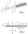
- FIG. 1is a perspective view showing an overall structure of an intraocular lens injector according to an embodiment of the present invention.
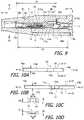
- FIG. 2is a side sectional view showing the overall structure of the intraocular lens injector according to an embodiment of the present invention.
- FIG. 3is a perspective view showing a state in which the intraocular lens injector of the embodiment of the present invention is housed in a case.
- FIG. 4is a perspective view showing a state in which the intraocular lens injector of the embodiment of the present invention is taken out from the case.
- FIG. 5(A)is a plan sectional view showing a structure of an essential part of the intraocular lens injector according to an embodiment of the present invention
- FIG. 5Bis a side sectional view showing the structure of the essential part
- FIG. 5Cis a partially enlarged view of FIG. 5B .
- FIGS. 6A to 6Dare views showing time-sequentially a state of a movement of a pushing member in accordance with a rotation operation of the operation portion.
- FIGS. 7A to 7Dare plan sectional views showing a state in which the intraocular lens is pushed out by the pushing member, in a chronological order.
- FIGS. 8A to 8Dare side sectional views showing a state in which the intraocular lens is pushed out by the pushing member, in a chronological order.
- FIG. 9is a sectional view showing an essential part of the intraocular lens injector according to a second embodiment of the present invention.
- FIGS. 10A to 10Dare views for explaining the structure of a lower groove and an upper groove
- FIG. 10Ais a schematic view when the upper groove is viewed from a position of a central axis of the injector main body
- FIG. 10Bis a schematic view when the lower groove is viewed from the position of the central axis of the injector main body
- FIG. 10Cis a view showing a sectional structure of the upper groove at a position V 1 -V 1 of FIG. 10A
- FIG. 10Dis a view showing the sectional structure of the lower groove at a position V 2 -V 2 of FIG. 10B .
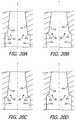
- FIGS. 11A to 11Care views (part 1 ) for explaining an operation of the intraocular lens injector according to the second embodiment of the present invention.
- FIGS. 12A and 12Bare views (part 2 ) for explaining the operation of the intraocular lens injector according to the second embodiment of the present invention.
- FIG. 13is an enlarged plan view of the essential structure of the intraocular lens injector according to a third embodiment of the present invention.
- FIGS. 14A to 14Care plan sectional views (part 1 ) showing time-sequentially a state of pushing out the intraocular lens in the intraocular lens injector, using a pushing member according to the third embodiment of the present invention.
- FIGS. 15A to 15Care plan sectional views (part 2 ) showing time-sequentially the state of pushing out the intraocular lens in the intraocular lens injector using the pushing member according to the third embodiment of the present invention.
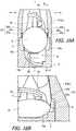
- FIGS. 16A and 16Bshow an internal structure of a joint portion between the injector main body and an injection tube as an essential part of the intraocular lens injector according to a comparative embodiment of the present invention, where FIG. 16A is a view of the internal structure of the joint portion viewed from above, and FIG. 16B is a perspective view of the internal structure of the joint portion viewed from backside.
- FIGS. 17(A) and 17(B)are views showing a state of the movement of the intraocular lens in an intraocular lens injector according to a comparative embodiment of the present invention.
- FIGS. 18A and 18Bthe internal structure of the joint portion between the injector main body and the injection tube as the essential part of the intraocular lens injector according to a fourth embodiment of the present invention, where FIG. 18A is a view of the internal structure of the joint portion viewed from above, and FIG. 18B is a perspective view of the internal structure of the joint portion viewed from the backside.
- FIGS. 19A and 19Bare views showing a state of the movement of the intraocular lens in an intraocular lens injector according to a fourth embodiment of the present invention.
- FIGS. 20A to 20Dare views showing an example of the structure of a protrusion according to a fourth embodiment of the present invention.
- FIG. 1is a perspective view showing an overall structure of an intraocular lens injector according to an embodiment of the present invention
- FIG. 2is a side sectional view showing the overall structure of the intraocular lens injector according to an embodiment of the present invention.
- An intraocular lens injector 1 shown in the figureis provided as a disposable product, and is used when injecting the intraocular lens into the eye.
- the intraocular lens injector 1is of a preload type in which an intraocular lens is preset.
- the intraocular lensis preset on the lens setting portion described later in the stage of shipping the intraocular lens injector 1 from a factory.
- X 1 directionis set as a tip end side (front side)
- X 2 directionis set as a rear end side (rear side)
- Y 1 directionis set as a right side (right side)
- Y 2 directionis set as a left side (left side)
- Z 1 directionis set as an upper side (upper side)
- Z 2 directionis set as a lower side (lower side).
- the X 1 direction and the X 2 directioncorrespond to a direction of a central axis of the intraocular lens injector 1 (hereinafter also referred to simply as a “central axis direction”)
- the Y 1 direction and the Y 2 directioncorrespond to a width direction (left-right direction) of the intraocular lens injector 1
- the Z 1 direction and the Z 2 directioncorrespond to a height direction (vertical direction) of the intraocular lens injector 1
- a plane parallel to the X 1 direction, the X 2 direction, the Y 1 direction and the Y 2 directionis set as a horizontal plane
- a plane perpendicular to the horizontal planeis set as a vertical plane.
- Reference symbol J in the figureindicates the central axis of the intraocular lens injector 1 .
- the intraocular lens injector 1is provided to a user in a state of being housed in a case 100 .
- the case 100is made of resin.
- the case 100is structured to open upward so that the intraocular lens injector 1 can be attached and detached.
- the case 100is formed with an opening/closing cover 101 for partially closing an upper part of the case 100 and an injection cover 102 for opening/closing together with the opening/closing cover 101 .
- the case 100has a space capable of housing the intraocular lens injector 1 , in which the intraocular lens injector 1 is housed.
- the opening/closing cover 101is in a closed state ( FIG. 3 ), and when the intraocular lens injector 1 is taken out from the case 100 , the opening/closing cover 101 is in an open state ( FIG. 4 ).
- the opening/closing cover 101is in a closed state, the intraocular lens injector 1 housed in the case 100 is pressed from above by the opening/closing cover 101 .
- the opening/closing cover 101is in an open state, the upper part of the case 100 is opened.
- An opening/closing operation of the opening/closing cover 101is performed by a manufacturer or the user of the intraocular lens injector 1 .
- the opening/closing cover 101includes a hooking portion 103 .
- the hooking portion 103is a portion for hooking a user's finger when opening/closing the opening/closing cover 101 .
- a slit 104is formed in the opening/closing cover 101 .
- the slit 104is formed in the vicinity of the hooking portion 103 .
- a protrusion 105is formed in the case 100 as shown in FIG. 4 . The protrusion 105 is engaged with the slit 104 when the opening/closing cover 101 is closed, thereby holding the opening/closing cover 101 in a closed state.
- the injection lid 102is for injecting a viscoelastic substance.
- a small holeis formed in the injection lid 102 , and a part of the injection lid 102 is formed in a funnel shape around this hole.
- the injection lid 102is partially connected to the opening/closing cover 101 so as to move together with the opening/closing cover 101 .
- the case 100is marked with numbers 106 , 107 , and 108 .
- Numbers attached to each of the marks 106 , 107 , and 108indicate procedures of work to be performed by the user when taking out the intraocular lens injector 1 from the case 100 .
- arrows attached to the marks 107 and 108indicate directions of work to be performed by the user.
- the mark 106 with the number “1” attached theretoindicates that the operation of injecting the viscoelastic substance through the injection lid 102 should be performed.
- the mark 107 with the numeral “2” attached theretoindicates that the operation of opening the opening/closing cover 101 in the direction of the arrow should be performed
- the mark 108 with the numeral “3” attached theretoindicates that the operation of taking out the intraocular lens injector 1 in the direction of the arrow should be performed.
- the intraocular lens injector 1roughly includes an injector main body 2 , an operation part 3 , an injection tube 4 , and a pushing member 5 .
- Each part of the intraocular lens injector 1is made of resin.
- the injector main body 2is formed in a tubular shape as a whole.
- a hollow portion that allows the movement of the pushing member 5 in the X 1 direction and the X 2 directionis formed inside of the injector main body 2 .
- a lens setting portion 6is provided at a tip end part of the injector main body 2 .
- the lens setting portion 6is formed so as to protrude forward from an outer circumferential wall on a lower side of the injector main body 2 .
- the intraocular lens 7is set on the lens setting portion 6 (see FIGS. 5A to 5C ).
- a central axis J of the intraocular lens injector 1coincides with each central axis of the injector main body 2 , the operation part 3 , and the injection tube 4 .
- one-piece type intraocular lens 7made of a soft material such as silicone elastomer or soft acrylic is to be handled.
- the intraocular lens 7has an optical portion 8 that performs an optical function and a pair (two) support portions 9 a , 9 b extending outwardly from the outer peripheral edge of the optical portion 8 in an arc shape.
- the optical portion 8is formed in a circular shape in plan view.
- Each of the pair of support portions 9 a , 9 bis formed in an elongated arm shape.
- a guide slope 11is formed on an upper surface of the lens setting portion 6 .
- the guide slope 11constitutes a guide mechanism for guiding the movement of the pushing member 5 when the pushing member 5 moves in the central axis direction of the injector main body 2 .
- the guide slope 11is formed on a moving path of the pushing member 5 in a state in which a part of the lens setting portion 6 is protruded (raised) upward.
- the guide slope 11has an inclined portion 11 a inclined with respect to a horizontal plane, a top portion 11 b not inclined, and a step portion 11 c perpendicular to the horizontal plane.
- the inclined portion 11 ais inclined in a state in which the inclined portion 11 a gradually becomes higher from the back of the lens setting portion 6 toward the front.
- the inclined portion 11 ais inclined obliquely upward from the upstream side to the downstream side in the moving direction of the pushing member 5 .
- the top portion 11 bis formed to extend horizontally from an uppermost portion of the inclined portion 11 a .
- the step portion 11 cis formed in a state of falling vertically from the tip end of the top portion 11 b.
- a pair of right and left recessed groovesare formed in the lens setting portion 6 .
- the pair of recessed groovesare formed on the left and right side walls defining the lens setting portion 6 of the injector main body 2 so as to face each other.
- the intraocular lens 7is set on the lens setting portion 6 having the abovementioned structure, in a state in which one of the support portions 9 a is disposed in front of the lens setting portion 6 and the other support portion 9 b is disposed behind the lens setting portion 6 . Further, the intraocular lens 7 is approximately horizontally set (placed) on the lens setting portion 6 in a state in which a rear edge of the optical portion 8 faces the step portion 11 c of the guide slope 11 . In FIG. 2 , the notation of the intraocular lens 7 is omitted.
- the operation portion 3is coaxially connected to the rear end part of the injector main body 2 . In this connected state, the operation portion 3 is supported so as to be rotatable around the central axis of the injector main body 2 .
- the operation portion 3is formed into a tubular shape.
- a plurality of protrusions 3 aare formed on the outer peripheral surface of the operation portion 3 . Each protrusion 3 a is formed in parallel to a longitudinal direction of the operation portion 3 .
- the operation portion 3is a portion rotated by a user such as an operator when the intraocular lens 7 is pushed out using the pushing member 5 .
- an initial statewhich is a state of the intraocular lens injector 1 .
- a first screw portion 3 bis formed on the inner peripheral surface of the operation portion 3 .
- the first screw portion 3 bconstitutes a female screw.
- the first screw portion 3 bis formed substantially throughout the central axis direction of the operation portion 3 .
- An abutting portion 3 cis formed at a rear end part of the operation portion 3 .
- the abutting portion 3 cis formed by bending inward so as to narrow an opening diameter of the rear end part of the operation portion 3 .
- the abutting portion 3 cis a portion where the rear end part of a plunger portion 17 abuts so that the plunger portion 17 does not protrude rearward from the rear end part of the operation portion 3 .
- An injection tube 4functions to guide the intraocular lens 7 set on the lens setting portion 6 into an eye in a state that the intraocular lens 7 is folded into a small size when the intraocular lens 7 is injected into the eye.
- the injection tube 4integrally has a hollow injection tube main body 4 a and a narrow tubular nozzle portion 4 b .
- the injection tube 4is attached to a tip end part of the injector main body 2 . In this attachment state, the lens setting portion 6 of the injector main body 2 is housed in the injection tube main body 4 a of the injection tube 4 .
- the space inside of the injection tube main body 4 ais gradually narrowed toward the nozzle portion 4 b , for small folding of the intraocular lens 7 pushed out from the lens setting portion 6 to the injection tube 4 .
- the intraocular lens 7is finally rounded and folded so as to embrace the pair of support portions 9 a and 9 b with the optical portion 8 .
- the nozzle portion 4 bis formed at the tip end part of the injection tube 4 .
- the tip end part of the nozzle portion 4 bopens with an oblique incision. Therefore, the opening of the nozzle portion 4 b faces obliquely downward.
- the tip end part of the nozzle portion 4 bis a portion to be inserted into an incisional wound of the eyeball when the intraocular lens 7 is injected into the eye using the intraocular lens injector 1 .
- An injection portion 4 cis formed on an upper wall of the injection tube main body 4 a , and a through hole 4 d is formed on a lower wall of the injection tube main body 4 a .
- the injection portion 4 cis a portion for injecting a viscoelastic substance (for example, sodium hyaluronate etc.).
- the through hole 4 dis a portion into which a pin (not shown) provided vertically erect on the bottom of the abovementioned case 100 is inserted. Such a pin is disposed to protrude through the through hole 4 d in the vicinity of a base end portion of the support portion 9 b , when the intraocular lens injector 1 incorporating the intraocular lens 7 therein, is housed in the case 100 .
- the pushing member 5is provided movably in the central axis direction of the injector main body 2 .
- the pushing member 5functions to push out the intraocular lens 7 form the lens setting portion 6 by moving in the central axis direction (X 1 direction) of the injector main body 2 .
- the pushing member 5moves in the hollow portion formed by the injector main body 2 , the operation portion 3 , and the injection tube 4 .
- the pushing member 5has the plunger portion 17 and a rod portion 18 .
- the plunger portion 17 and the rod portion 18may constitute the pushing member 5 in a unitary structure, or the plunger portion 17 and the rod portion 18 may have separate structures and they may be mutually assembled to constitute the pushing member 5 .
- the plunger portion 17is disposed relatively rearwardly, and the rod portion 18 is disposed relatively forward in the direction of the central axis of the intraocular lens injector 1 . Therefore, the tip end part of the pushing member 5 corresponds to the tip end part of the rod portion 18 .
- the plunger portion 17is formed into a rod shape. In the initial state before use, the plunger portion 17 is disposed in a state of being inserted into the operation portion 3 so as not to protrude from the rear end part of the operation portion 3 .
- a second screw portion 17 ais formed at the rear end part of the plunger portion 17 .
- the second screw portion 17 aconstitutes a male screw.
- the second screw portion 17 ais engaged with the first screw portion 3 b inside of the operation portion 3 .
- the operation portion 3is operated so as to rotate around the central axis of the injector main body 2 , thereby moving the entire pushing member 5 in a forward direction.
- a movement start position of the plunger portion 17 at that timeis uniquely determined by abutting the rear end part of the plunger portion 17 against the abutting portion 3 c of the operation portion 3 .
- the pushing member 5moves in the central axis direction of the injector main body 2 , and in this state, the rod portion 18 functions to release the intraocular lens 7 from the opening of the nozzle portion 4 b of the injection tube 4 , by pushing out the intraocular lens 7 forward, which is set on the lens setting portion 6 is pushed out.
- the rod portion 18is formed into a rod shape thinner than the plunger portion 17 .
- the rod portion 18is configured to be elastically deformable so as to have moderate flexibility.
- a first contact portion 18 a and a second contact portion 18 bare formed at the tip end part of the rod portion 18 .
- the first contact portion 18 acomes into contact with the support portion 9 b and the second contact portion 18 b comes into contact with the optical portion 8 .
- the upper end portion of the second contact portion 18 bprotrudes like a canopy so as to grip the edge of the optical portion 8 .
- the lower surface of the tip end side of the rod portion 18is an inclined surface 18 c gently inclined rearward from the second contact portion 18 b .
- the inclined surface 18 cis formed to displace the tip end part of the rod portion 18 upward along the inclined portion 11 a of the guide slope 11 in the middle of the movement, and thereafter displace the tip end part of the rod portion 18 downward using the inclination of the inclined surface 18 c.
- the pushing member 5is attached to the operation portion 3 .
- the tip end opening part of the operation portion 3is engaged with the rear end part of the plunger portion 17 of the pushing member 5 so as to cover this opening part, so that the operation portion 3 is rotated.
- the first screw portion 3 b formed on the inner peripheral surface of the operation portion 3 and the second screw portion 17 a provided at the rear end part of the plunger portion 17are engaged with each other. Therefore, when the operation portion 3 is rotated while restricting the rotation of the pushing member 5 , the plunger portion 17 is inserted into the operation portion 3 in accordance with the rotation of the operation portion 3 . At this time, the operation portion 3 is rotated until the rear end part of the plunger portion 17 abuts against the abutting portion 3 c of the operation portion 3 .
- the injector main body 2is attached to the operation portion 3 .
- the rod portion 18 of the pushing member 5is inserted into the hollow portion of the injector main body 2 .
- the tip end parts ( 18 a , 18 b ) of the rod portion 18are disposed slightly in front of the lens setting portion 6 .
- the separately prepared intraocular lens 7is horizontally set on the lens setting portion 6 of the injector main body 2 .
- the optical portion 8 of the intraocular lens 7is disposed slightly forward of the step portion 11 c of the guide slope 11 .
- one support portion 9 ais disposed frontward and the other support portion 9 b is disposed rearward.
- the tip end side of the support portion 9 bis disposed to block the moving direction of the rod portion 18 .
- the intraocular lens 7is set in a no-load state.
- the no-load staterefers to a state in which almost no load (pressure) is applied to the intraocular lens, that is, a state in which the intraocular lens maintains its original shape.
- the original shape of the intraocular lensrefers to the shape in the stage of finishing manufacturing the intraocular lens.
- the injection tube 4is attached to the tip end part of the injector main body 2 .
- the assembly of the intraocular lens injector 1 incorporating the intraocular lens 7is completed.
- the structure for connecting the injector main body 2 and the operation portion 3 and the structure for connecting the injector main body 2 and the injection tube 4for example, the structure described in the specification of Japanese Patent Application No. 2014-55761 and drawings (Japanese Patent Application Laid-open No. 2015-177845) may be adopted, or any other connecting structure may be adopted.
- the intraocular lens injector 1After the assembly of the intraocular lens injector 1 is completed as described above, the intraocular lens injector 1 is housed in the case 100 , and the opening/closing cover 101 is closed. At this time, the injection lid 102 of the case 100 is placed over the injection part 4 c of the intraocular lens injector 1 . In this state, the intraocular lens injector 1 is stored in a sterilized bag or the like together with the case 100 .
- the usertakes out the intraocular lens injector 1 from a sterilized bag or the like together with the case 100 .
- the userinjects the viscoelastic substance from the injection lid 102 in accordance with an instruction of the mark 106 .
- the viscoelastic substanceis injected (supplied) from the injection lid 102 through the injection portion 4 c to the intraocular lens 7 set on the lens setting portion 6 .
- the useropens the opening/closing cover 101 in accordance with the instruction of the mark 107 . Then, it is possible to obtain a state in which the mark 108 hidden by the opening/closing cover 101 is visible. Therefore, the user takes out the intraocular lens injector 1 from the case 100 in accordance with the instruction of the mark 108 .
- the pushing member 5moves forward by the engagement between the first screw portion 3 b and the second screw portion 17 a .
- the plunger portion 17 of the pushing member 5moves straight in the central axis direction (X 1 direction) of the injector main body 2 while engaging with the hollow portion of the injector main body 2 .
- the pushing member 5moves as shown in FIGS. 6A to 6D in accordance with the rotation operation of the operation portion 3 .
- FIG. 6Ashows a stage in which the tip end part of the rod portion 18 of the pushing member 5 is advanced to the tip end part of the lens setting portion 6
- FIG. 6Bshows a stage in which the tip end part of the rod portion 18 is advanced to the injection tube main body 4 a of the injection tube 4
- FIG. 6Cshows a stage in which the tip end part of the rod portion 18 is advanced to the nozzle portion 4 b of the injection tube 4
- FIG. 7Dshows a stage in which the tip end part of the rod portion 18 protrudes forward from the nozzle portion 4 b of the injection tube 4 .
- the tip end part of the rod portion 18moves forward so as to push out the intraocular lens 7 from the lens setting portion 6 .
- the tip end part of the rod portion 18pass the lens setting portion 6 mainly through four stages, by being guided by the guide slope 11 . This state is shown in a plane sectional view of FIGS. 7A to 7D and a side sectional view of FIGS. 8A to 8D . Each stage will be described hereafter in detail.
- the first stageis the stage in which the tip end part of the rod portion 18 comes into contact with the support portion 9 b as shown in FIGS. 7A and 8A .
- the first contact portion 18 a at the tip end of the rod portion 18comes into contact with the tip end side of the support portion 9 b .
- the tip end side of the support portion 9 bis supported in a manner of riding onto the first contact portion 18 a.
- the second stageis the stage of pushing the support portion 9 b while the tip end part of the rod portion 18 comes into contact with the support portion 9 b , as shown in FIGS. 7B and 8B .
- the tip end part of the rod portion 18reaches the inclined portion 11 a of the guide slope 11 .
- an upward forceis applied to the tip end part of the rod portion 18 .
- the tip end part of the rod portion 18is displaced upward due to an elastic deformation of the rod portion 18 itself. Therefore, the tip end part of the rod portion 18 moves forward so as to push the support portion 9 b while being displaced upward along the inclined portion 11 a of the guide slope 11 .
- the support portion 9 bis gradually bent. Further, the tip end side of the support portion 9 b is gradually raised.
- the pair of support portions 9 a and 9 bare made of a material which is soft and easily elastically deformed, even if the support portion 9 b is pushed in by the tip end part of the rod portion 18 , the pushing force is absorbed by deformation of the support portion 9 b . Therefore, even if the support portion 9 b is pushed in by the tip end part of the rod portion 18 , the position of the optical portion 8 hardly changes from an initial state.
- the third stageis the stage in which the tip end part of the rod portion 18 comes into contact with the optical portion 8 , as shown in FIGS. 7C and 8C .
- the tip end part of the rod portion 18comes into contact with the optical portion 8 by reaching the top portion 11 b of the guide slope 11 and passing therethrough.
- the second contact portion 18 b formed at the tip end part of the rod portion 18comes into contact with the edge of the optical portion 8 .
- the support portion 9 bis further bent by the forward movement of the rod portion 18 .
- the support portion 9 b as a wholeis bent toward the optical portion 8 so as to form a substantially U-shape.
- the tip end side of the support portion 9 bis properly raised before the tip end part of the rod portion 18 comes into contact with the optical portion 8 . Therefore, the tip end part of the support portion 9 b is less likely to catch on the edge of the optical portion 8 , and in this situation, the tip end part of the support portion 9 b rides onto the surface of the optical portion 8 .
- the fourth stageis the stage in which the tip end part of the rod portion 18 pushes the entire intraocular lens 7 while coming into contact with the support portion 9 b and the optical portion 8 , as shown in FIGS. 7D and 8D .
- a downward forceis exerted on the tip end part of the rod portion 18 by a reaction force due to the elastic deformation of the rod portion 18 itself, and therefore the inclined surface 18 c of the rod portion 18 is pushed against the edge portion (the upper end of the step portion 11 c ) of the lower guide slope 11 . Therefore, the tip end part of the rod portion 18 is gradually displaced downward in accordance with the inclination of the inclined surface 18 c immediately after passing through the step portion 11 c of the guide slope 11 , and finally returns to an original height position.
- the intraocular lens 7thus pushed out from the lens setting portion 6 , is subsequently pushed by the rod portion 18 and moves forward in the injection tube 4 .
- the optical portion 8 of the intraocular lens 7is rounded from the left and right by the inner wall of the injection tube main body 4 a having a tapered shape, and is finally folded so as to embrace the pair of support portions 9 a , 9 b .
- the support portion 9 ais bent in conformity with the shape of the gradually narrowed space in the injection tube 4 (see FIG. 7D ).
- the intraocular lens 7 thus foldedis pushed out from the nozzle portion 4 b of the injection tube 4 by the rod portion 18 .
- the intraocular lens 7can be injected into the eye.
- the tip end part of the rod portion 18is guided by the guide mechanism so as to be displaced in a direction (vertical direction in this embodiment) intersecting the central axis of the injector main body 2 , when the pushing member 5 moves in the central axis direction of the injector main body 2 .
- the guide slope 11 in the injector main body 2by forming the guide slope 11 in the injector main body 2 and displacing the tip end part of the rod portion 18 in the vertical direction along the guide slope 11 , it is possible to raise the tip end side of the support portion 9 b upward. Therefore, it is possible to create a situation in which the tip end part of the support portion 9 b is easy to ride on the surface of the optical portion 8 .
- the tip end part of the rod portion 18pushes the support portion 9 b while being displaced upward along the inclined portion 11 a of the guide slope 11 . Therefore, it is possible to perform the operation of bending the support portion 9 b and the operation of raising the support portion 9 b in parallel in a series of pushing operations by the pushing member 5 .
- FIGS. 1 to 8Dthe abovementioned embodiment
- the other embodimentsare referred to as a second embodiment, a third embodiment and the like, respectively.
- the same reference numeralsare given to the same parts as those of the embodiment (the first embodiment) described above.
- the structure of the guide mechanism for guiding the movement of the pushing member 5is different from that of the abovementioned first embodiment.
- the guide slope 11is formed on the lens setting portion 6 of the injector body 2 , and the guide mechanism is constituted by this guide slope 11 .
- guide slopesare respectively provided on the upper side and the lower side of a moving path of the pushing member 5 , and the guide mechanism is constituted by these guide slopes.
- the guide mechanism of the second embodimentincludes a suppressing portion for suppressing a lateral shake of the tip end part of the pushing member 5 .
- FIG. 9is a sectional view showing an essential part of the intraocular lens injector according to the second embodiment of the present invention.
- FIG. 9is a view obtained by vertically sectioning the essential part of the intraocular lens injector on the central axis J ( FIG. 1 ), wherein a left direction corresponds to the X 1 direction, a right direction corresponds to the X 2 direction, an upward direction corresponds to the Z 1 direction, and a downward direction corresponds to the Z 2 direction in the figure.
- the guide mechanism for guiding the movement of the pushing member 5is constituted by the lower guide slope 11 and the upper guide slope 12 .
- the lower guide slope 11is constituted by the inclined portion 11 a , the top portion 11 b and the step portion 11 c .
- the upper guide slope 12is constituted by the inclined portion 12 a .
- the lower guide slope 11is formed on the lens setting portion 6 of the injector main body 2
- the upper guide slope 12is formed on the inner wall of the injection tube 4 .
- the inclined portion 12 a of the upper guide slope 12is disposed on the downstream side of the inclined portion 11 a of the lower guide slope 11 .
- the lower guide slope 11displaces the tip end part of the rod portion 18 of the pushing member 5 upward using the inclined portion 11 a
- the upper guide slope 12displaces the tip end part of the rod portion 18 downward using the inclined portion 12 a . Therefore, the inclined portion 11 a of the lower guide slope 11 is inclined obliquely upward from the upstream side toward the downstream side in the moving direction (X 1 direction) of the pushing member 5
- the inclined portion 12 a of the upper guide slope 12is inclined obliquely downward from the upstream side to the downstream side in the moving direction (X 1 direction) of the pushing member 5 .
- grooves 13 , 14are formed in pairs at upper and lower positions on the lens setting portion 6 of the injector main body 2 , and the upper wall portion inside of the insertion tube 4 opposed to the lens setting portion 6 .
- the groves 13 and 14constitute a suppressing portion for suppressing the lateral shake of the tip end part of the pushing member 5 when the pushing member 5 moves in the central axis direction of the injector main body 2 .
- the term “lateral shake of the tip end part of the pushing member 5 ”refers to a situation that the tip end part of the rod portion 18 swings in the left-right direction when the pushing member 5 waiting behind the lens installing portion 6 is moved in the X 1 direction by the rotation operation of the operation portion 3 .
- the tip end part of the pushing member 5swings horizontally, the tip end part of the rod portion 18 cannot be stably brought into contact with a target position of the intraocular lens 7 .
- the groove 13is formed on the lower side of the movement path of the rod portion 18
- the groove 14is formed on the upper side of the movement path of the rod portion 18 . Therefore, the groove 13 and the groove 14 are opposed to each other in a vertical direction interposing the movement path of the rod portion 18 .
- the lower groove 13is referred to as a lower groove 13
- the upper groove 14is referred to as an upper groove 14 .
- FIGS. 10A to 10Dare views for explaining the structure of the lower groove and the upper groove
- FIG. 10Ais a schematic view when the upper groove is viewed from the position of the central axis of the injector main body
- FIG. 10Bis a schematic view when the lower groove is viewed from the position of the central axis of the injector main body
- FIG. 10Cis a view showing a sectional structure of the upper groove at the position V 1 -V 1 of FIG. 10A
- FIG. 10Dis a view showing a sectional structure of the lower groove at the position V 2 -V 2 of FIG. 10B .
- the lower groove 13 and the upper groove 14are formed so as to be engaged with the tip end part of the rod portion 18 of the pushing member 5 in order to suppress the lateral shake of the tip end part of the pushing member 5 .
- the lower groove 13is recessed downward and the upper groove 14 is recessed upward.
- a width W 1 of the lower groove 13is set corresponding to a width of the tip end part of the rod portion 18
- a width W 2 of the upper groove 14is also set corresponding to a width dimension of the tip end part of the rod portion 18 .
- FIG. 9shows a state before the operation portion 3 of the intraocular lens injector 1 is rotated, namely, shows an initial state. In this initial state, the tip end part of the rod portion 18 receives a downward force.
- This downward forcecan be generated, for example, by elastically deforming the rod portion 18 itself so as to press the tip end part of the rod portion 18 downward. This point is the same in the first embodiment as well. Further, in the initial state, the lower side of the tip end part of the rod portion 18 is engaged with the lower groove 13 .
- a range S 1 for forming the lower groove 13is a range from a tip end 13 a to a rear end 13 b of the lower groove 13
- a range S 2 for forming the upper groove 14is a range from a tip end 14 a to a rear end 14 b of the upper groove 14
- the lower guide slope 11is included in the range S 1 of the lower groove 13
- the upper guide slope 12is included in the range S 2 of the upper groove 14
- the lower groove 13 and the upper groove 14are formed linearly respectively along the central axis direction of the intraocular lens injector 1 .
- the lower guide slope 11is formed in the middle of the lower groove 13
- the upper guide slope 12is formed in the middle of the upper groove 14 .
- the tip end 13 a of the lower groove 13is disposed at substantially the same position as the tip end 14 a of the upper groove 14
- the rear end 13 b of the lower groove 13is disposed at a position displaced rearward from the rear end 14 b of the upper groove 14 . Therefore, the range S 1 of the lower groove 13 is wider (longer) than the range S 2 of the upper groove 14 .
- the lower groove 13is partly interrupted by the protrusion of the lower guide slope 11 .
- the upper groove 14is continuously formed in the middle of the range S 2 without interruption.
- a depth D 1 of the lower groove 13is substantially uniform throughout the range S 1 .
- the depth D 1 of the lower groove 13gradually becomes shallow.
- a depth D 2 of the upper groove 14is deeper on the upstream side than the downstream side of the upper side guide slope 12 . Further, in the portion where the upper guide slope 12 is formed, the depth D 2 of the upper groove 14 is continuously changed in accordance with the inclination of the inclined portion 12 a.
- FIG. 11Ashows a stage in which the tip end part of the rod portion 18 of the pushing member 5 moves to a position in front of the lower guide slope 11
- FIG. 8Bshows a stage in which the tip end part of the rod portion 18 moves to the inclined portion 11 a of the lower guide slope 11
- FIG. 5Cshows a stage in which the tip end part of the rod portion 18 is moved to the top portion 11 b of the lower guide slope 11
- FIG. 12Ashows a stage in which the tip end part of the rod portion 18 moves forward of the lower guide slope 11
- FIG. 8Bshows a stage in which the tip end part of the rod portion 18 moves forward of the upper guide slope 12 .
- the tip end part of the rod portion 18moves forward while being engaged with the lower groove 13 , and during this movement, the first contact portion 18 a of the rod portion 18 comes into contact with the support portion 9 b of the intraocular lens 7 . Thereby, the tip end side of the support portion 9 b is supported in a manner of riding onto the first contact portion 18 a . Further, the tip end part of the rod portion 18 also engages with the upper groove 14 in the middle of the movement.
- the tip end part of the rod portion 18moves while displacing upward along the inclined portion 11 a of the lower guide slope 11 .
- the tip end part of the rod portion 18moves so as to push the support portion 9 b while displacing upward by the elastic deformation of the rod portion 18 itself.
- the support portion 9 bis gradually bent.
- the tip end side of the support portion 9 bis gradually raised.
- the tip end part of the rod portion 18reaches the top portion 11 b while displacing upward along the inclined portion 11 a of the lower guide slope 11 , and thereafter moves along the top portion 11 b .
- the tip end part of the rod portion 18moves while being engaged with the upper groove 14 .
- the second contact portion 18 b of the rod portion 18comes into contact with the edge of the optical portion 8 in the middle of or immediately after passing through the top portion 11 b.
- the tip end part of the rod portion 18moves while being displaced downward along the inclined portion 12 a of the upper guide slope 12 .
- the tip end part of the rod portion 18moves while being engaged with the upper groove 14 , and passes through the lower guide slope 11 , and thereafter is engaged with the lower groove 13 again, and returns to an original height position.
- the tip end parts ( 18 a , 18 b ) of the rod portion 18push the entire intraocular lens 7 while being in contact with the support portion 9 b and the optical portion 8 . Therefore, the intraocular lens 7 further moves forward from the initial state.
- the guide slope 11 similar to that of the first embodimentis formed, and therefore even if the upper guide slope 12 is not formed, it is possible to displace the tip end part of the rod portion 18 downward by the same principle as in the first embodiment.
- a reaction force due to the elastic deformation of the rod portion 18becomes weaker, and therefore there is a possibility that the operation of the rod portion 18 becomes unstable when the tip end part of the rod portion 18 rides onto the lower guide slope 11 . Accordingly, in order to operate the rod portion 18 more stably, it is preferable to form the upper guide slope 12 .
- the upper end of the tip end part of the rod portion 18approaches or comes into contact with the inclined portion 12 a of the upper guide slope 12 , immediately after the tip end part of the rod portion 18 passes through the step portion 11 c of the lower guide slope 11 . Therefore, the tip end part of the rod portion 18 is forcibly displaced downward along the inclined portion 12 a of the upper guide slope 12 . Accordingly, the displacement operation of the rod portion 18 becomes more stable.
- the tip end part of the rod portion 18moves while being engaged with both the lower groove 13 and the upper groove 14 .
- the tip end parts ( 18 a , 18 b ) of the rod portion 18further push the entire intraocular lens 7 while coming into contact with the support portion 9 b and the optical portion 8 .
- the tip end part of the rod portion 18moves further forward while being engaged with both the lower groove 13 and the upper groove 14 .
- the tip end part of the rod portion 18disengages from the lower groove 13 at the stage of passing through the distal end 13 a of the lower groove 13 , and disengages from the upper groove 14 at the stage of passing through the tip end 14 a of the upper groove 14 . Therefore, the tip end part of the rod portion 18 moves while being engaged with both the lower groove 13 and the upper groove 14 except when it passes through the portion of the lower guide slope 11 . Further, the tip end part of the rod portion 18 moves while being engaged with the upper groove 14 when it passes through the portion of the lower guide slope 11 . Accordingly, the end portion of the rod portion 18 is continuously suppressed from the lateral shake due to the engagement with at least one of the grooves 13 , 14 until the end of the passage through the ranges S 1 , S 2 of the grooves 13 , 14 .
- the guide mechanism for guiding the movement of the pushing member 5is constituted by the lower guide slope 11 and the upper guide slope 12 . Therefore, it is possible to more stably perform the operation of vertically displacing the tip end part of the rod portion 18 of the pushing member 5 .
- the lateral shake of the tip end part of the rod portion 18is suppressed by the upper and lower grooves 13 and 14 when the tip end part of the rod portion 18 of the pushing member 5 is displaced in the vertical direction. Therefore, the tip end part of the rod portion 18 can be advanced straight. Accordingly, it is possible to bring the tip end part of the rod portion 18 into stable contact with the target position of the intraocular lens 7 .
- the lower groove 13 and the upper groove 14are formed in order to suppress the lateral shake of the tip end part of the pushing member 5 .
- a structure other than the groovemay be adopted as long as it exhibits the same function.
- the one-piece type intraocular lens 7is made of a very soft material, and therefore when the support portion 9 b is pushed in by the rod portion 18 , there is a possibility that the shape of the support portion 9 b is largely collapsed because the support portion 9 b does not bend into a shape as expected by design. When such a phenomenon occurs, even if the support portion 9 b is pushed by the rod portion 18 , the tip end part of the support portion 9 b can not be placed on the surface of the optical portion 8 as specified.
- the intraocular lens injector 1suitable for handling the one-piece type intraocular lens 7 in which the entire intraocular lens 7 is made of a soft material.
- the intraocular lens injector 1 according to the third embodiment of the present inventioncan also be applied to a case of handling intraocular lenses other than the one-piece type.
- the structure of the lens setting portion 6 of the injector main body 2is different, compared to the first embodiment described above.
- the structure of the lens setting portion 6will be described hereafter in detail with reference to FIG. 13 .
- a guide groove 21is formed in the lens setting portion 6 .
- the guide groove 21constitutes a guide mechanism for guiding the movement of the tip end part of the pushing member 5 , when the pushing member 5 moves in the central axis direction of the injector main body 2 .
- the guide groove 21is formed in such a manner that the upper surface of the lens setting portion 6 is recessed in a concave shape in front of a region where the optical portion 8 is disposed in the lens setting portion 6 .
- the guide groove 21is curved with respect to the central axis J when the lens setting portion 6 is viewed from above.
- the upstream side (the right side in the figure) of the guide groove 21curves in the right direction Y 1 so as to be away from the position of the central axis J
- the downstream side (the left side in the figure) of the guide groove 21is curved in the left direction Y 2 so as to approach the position of the central axis J.
- the tip end part of the rod portion 18is engaged with the guide groove 21 .
- the tip end part of the rod portion 18is configured to move along the guide groove 21 while being engaged with the guide groove 21 . Further, when the tip end part of the rod portion 18 moves along the guide groove 21 , a starting end portion 21 a of the guide groove 21 which is a starting side of the movement is located on the central axis J in the left-right direction, and an end point 21 b of the guide groove 21 on the opposite side is also located on the central axis J in the left-right direction.
- the tip end part of the support portion 9 bis disposed so as to block a movement path of the rod portion 18 moving along the guide groove 21 , when the intraocular lens 7 is set on the lens setting portion 6 .
- the tip end part of the support portion 9 bis disposed at an middle point 21 c in a longitudinal direction of the guide groove 21 .
- a curved direction of the guide groove 21is switched from the right direction Y 1 to the left direction Y 2 , and the tip end part of the support portion 9 b is disposed in this portion.
- the tip end part of the rod portion 18moves as follows by being guided by the guide groove 21 .
- the tip end part of the rod portion 18starts to move from a starting point 21 a of the guide groove 21 located on the central axis J (see FIG. 13 ).
- the tip end part of the rod portion 18moves from the starting point 21 a to the middle point 21 c of the guide groove 21 (see FIG. 13 ) along the guide groove 21 .
- the tip end part of the rod portion 18moves (advances) while displacing to the right direction Y 1 , due to the elastic deformation of the rod portion 18 itself.
- the tip end part of the rod portion 18comes into contact with the tip end part of the support portion 9 b at a position where it reaches the middle point 21 c of the guide groove 21 (in other words, at a position deviated from the position of the central axis J in the right direction Y 1 ).
- the first contact portion 18 a formed at the tip end part of the rod portion 18comes into contact with the tip end part of the support portion 9 b .
- the tip end part of the support portion 9 bis supported in a manner of riding onto the first contact portion 18 a.
- the tip end part of the rod portion 18pushes the support portion 9 b while moving along the guide groove 21 .
- the support portion 9 bis gradually bent by the forward movement of the rod portion 18 .
- the tip end part of the rod portion 18moves (forwards) while displacing in the left direction Y 2 in accordance with the curve of the guide groove 21 .
- the tip end part of the rod portion 18comes into contact with the optical portion 8 when it reaches the end point 21 b (see FIG. 13 ) of the guide groove 21 located on the central axis J.
- the tip end part of the rod portion 18comes into contact with the optical portion 8 at the position of the central axis J passing through substantially the center of the optical portion 8 .
- the second contact portion 18 b formed at the tip end part of the rod portion 18comes into contact with the edge of the optical portion 8 .
- the support portion 9 bis further bent by the forward movement of the rod portion 18 along the guide groove 21 .
- the support portion 9 b as a wholeis bent toward the optical portion 8 so as to form a substantially U-shape.
- the tip end part of the rod portion 18pushes the entire intraocular lens 7 while being in contact with the support portion 9 b and the optical portion 8 .
- the tip end part of the rod portion 18has passed through the guide groove 21 . Therefore, the tip end part of the rod portion 18 moves straight along the central axis J.
- the descriptionis omitted since it is the same as the first embodiment described above.
- the tip end part of the rod portion 18is guided by the guide mechanism so as to be displaced in a direction crossing the central axis of the injector main body 2 (in the left-right direction in this embodiment).
- the position where the tip end part of the rod portion 18 comes into contact with the support portion 9 bis positioned closer to the middle point in the longitudinal direction of the support portion 9 b , as compared with the third embodiment.
- a risk that the tip end side of the support portion 9 b is bent in a direction different from an expected direction by designis increased when the support portion 9 b is pushed in by the tip end part of the rod portion 18 .
- the tip end part of the support portion 9 bcannot be placed on the surface of the optical portion 8 as specified.
- the tip end part of the rod portion 18is brought into contact with the tip end part of the support portion 9 b at a position deviated in the right direction Y 1 from the position of the central axis J, and thereafter the tip end part of the rod portion 18 is displaced in the left direction Y 2 and is brought into contact with the optical portion 8 at the position of the central axis J. Therefore, the tip end side of the support portion 9 b can be bent in the shape as expected by design when the support portion 9 b is pushed in by the tip end part of the rod portion 18 . Accordingly, the support portion 9 b can be bent into a shape as expected. As a result, it is possible to reliably place the tip end part of the support portion 9 b on the surface of the optical portion 8 .
- the guide groove 21 in the injector main body 2by forming the guide groove 21 in the injector main body 2 and displacing the tip end part of the rod portion 18 in the left-right direction along the guide groove 21 , it is possible to suppress the shape collapse of the support portion 9 b . Thereby, it is possible to bend the tip end side of the support portion 9 b into a shape as expected and place the tip end part of the support portion 9 b on the surface of the optical portion 8 .
- the structure of the injector main body 2 and the injection tube 4are different, as compared to the abovementioned first embodiment.
- a comparative embodiment of the present inventionwill be described, and thereafter the fourth embodiment of the present invention will be described.
- FIGS. 16A and 16Bshow an internal structure of a joint portion between the injector main body and an injection tube as an essential part of the intraocular lens injector according to a comparative embodiment of the present invention, where FIG. 16A is a view of the internal structure of the joint portion viewed from above, and FIG. 16B is a perspective view of the internal structure of the joint portion viewed from backside.
- Edge portions 15 a , 15 b for positioning the intraocular lens 7 placed thereonare formed in the lens setting portion 6 of the injector main body 2 .
- the edge portion 15 ais formed in a shape conforming to an outer shape of the optical portion 8
- the edge portion 15 bis formed in a shape conforming to an outer shape of the support portion 9 b .
- a stepis provided on each of the edge portions 15 a and 15 b , and positioning of the intraocular lens 7 can be performed by using this step difference.
- the optical portion 8is disposed along the edge portion 15 a , and the support portion 9 b is disposed along the edge portion 15 b , to thereby determine a setting position (hereinafter referred to as “an initial position”) of the intraocular lens 7 in an initial state.
- a position of the optical portion 8 at the time of setting the intraocular lens 7 at the initial positionis a position where the optical portion 8 starts moving when the intraocular lens 7 is pushed out by the pushing member 5 . Therefore, the movement start position of the optical portion 8 in the lens setting portion 6 is set using the edge portion 15 a.
- a pair of right and left side wall guides 22 , 22are formed from the lens setting portion 6 to the inside of the injection tube 4 in the central axis direction of the intraocular lens injector 1 .
- the pair of side wall guides 22have guide surfaces 22 a and 22 b respectively that regulate the position in the right and left direction of the optical portion 8 by bringing the optical portion 8 close to or in contact with the left and right edges of the optical portion 8 .
- One guide surface 22 ais formed in the lens setting portion 6 and the other guide surface 22 b is formed inside of the injection tube 4 .
- one guide surface 22 ais referred to as a first guide surface 22 a
- the other guide surface 22 bis referred to as a second guide surface 22 b.
- the first guide surface 22 ais formed on the lens setting portion 6 so as to be smoothly connected to the edge portion 15 a .
- the first guide surface 22 ais formed straight along the central axis J of the intraocular lens injector 1 .
- the second guide surface 22 bis formed on the side wall portion of the injection tube 4 so as to smoothly connect to the first guide surface 22 a .
- the second guide surface 22 bhas an inclination with respect to the central axis J of the intraocular lens injector 1 .
- the second guide surface 22 bis gradually inclined inward (toward the central axis J of the intraocular lens injector 1 ) from a joint portion 22 c between the first guide surface 22 a and the second guide surface 22 b .
- a distance in the left-right direction of the pair of side wall guides 22 , 22is as follows. First, in the portion where the first guide surface 22 a is formed, the distance is equal to or slightly larger than an outer diameter of the optical portion 8 . In contrast, in the portion where the second guide surface 22 b is formed, the diameter is gradually decreased from the joint portion 22 c with the first guide surface 22 a toward the nozzle portion 4 b ( FIG. 1 ) of the injection tube 4 .
- the intraocular lens 7when the intraocular lens 7 set on the lens setting portion 6 , is pushed out by the rod portion 18 of the pushing member 5 , the intraocular lens 7 starts moving from the initial position.
- the optical portion 8moves forward (in the X 1 direction) while being guided by the left and right first guide surfaces 22 a .
- the left and right edges of the optical portion 8reach the joint portion 22 c between the first guide surface 22 a and the second guide surface 22 b .
- the first guide surface 22 a and the second guide surface 22 bare smoothly connected. Therefore, the optical portion 8 moves forward without being caught by the joint portion 22 c.
- the second guide surface 22 bis slightly outwardly disposed as compared with the first guide surface 22 a so that the optical portion 8 is not caught by the joint portion 22 c .
- FIGS. 17A and 17Bin order to easily understand how much the intraocular lens 7 has moved from the initial position shown in FIGS. 16A and 16B , the shape of the rear support portion 9 b is shown in the same manner as in FIGS. 16A and 16B . However, actually the support portion 9 b is pushed by the rod portion 18 and set in a bent state.
- the optical portion 8moves further forward while being guided by the left and right second guide surfaces 22 b .
- the distance between the left and right second guide surfaces 22 bis gradually decreased toward the front, and accordingly, the space inside of the injection tube 4 is also gradually narrowed. Therefore, when the intraocular lens 7 is pushed out by the rod portion 18 , the optical portion 8 is gradually bent while being guided by the left and right second guide surfaces 22 b , and ultimately it is rounded small and folded.
- the first guide surface 22 a and the second guide surface 22 b of each side wall guide 22are smoothly connected. Therefore, the optical portion 8 of the intraocular lens 7 moves along the first guide surface 22 a and the second guide surface 22 b without stopping at the joint portion 22 c . In such a case, depending on the physical characteristics of the intraocular lens 7 , there is a possibility that the following troubles occurs.
- the pair of support portions 9 a , 9 bhave appropriate flexural rigidity to support the optical portion 8 in the eye. Therefore, depending on the intensity of the flexural rigidity of each of the support portions 9 a , 9 b , there is a possibility that the optical portion 8 starts to move in a state in which the bending deformation of the support portion 9 b is insufficient, namely, at a timing earlier than expected when the support portion 9 b is pushed in by the first contact portion 18 a of the rod portion 18 .
- the tip end part of the support portion 9 bis easily caught on the edge of the optical portion 8 .
- the reasonis as follows. A pair of right and left recessed grooves for limiting a vertical displacement amount of the optical portion 8 is formed in the lens setting portion 6 . Then in the initial state, the left and right outer peripheral parts of the optical portion 8 are disposed in the corresponding recessed grooves, thereby restricting the movement of the optical portion 8 in the vertical direction.
- FIGS. 18A and 18Bshow the internal structure of the joint portion between the injector main body and the injection tube as the essential part of the intraocular lens injector according to a fourth embodiment of the present invention
- FIG. 18Ais a view of the internal structure of the joint portion viewed from above
- FIG. 18Bis a perspective view of the internal structure of the joint portion viewed from the backside.
- the fourth embodimentis intended to solve the problem which may occur in the above comparative embodiment.
- the difference between the fourth embodiment and the comparative embodimentlies in the structure of the pair of side wall guides 22 , 22 .
- the first guide surface 22 a and the second guide surface 22 b of each side wall guide 22are smoothly connected.
- the first guide surface 22 a and the second guide surface 22 bare not connected smoothly but the protrusion 22 d is formed on the joint portion 22 c.
- the protrusion 22 dtemporarily stops the optical portion 8 of the intraocular lens 7 pushed out by the pushing member 5 .
- the protrusion 22 dis formed at the joint portion 22 c so that the second guide surface 22 b protrudes inward from the first guide surface 22 a (a side close to the central axis J of the intraocular lens injector 1 ) by a predetermined dimension Ly.
- the distance between the left and right side wall guides 22 , 22is shorter than the diameter of the optical portion 8 due to the protrusion of the protrusion 22 d . Therefore, when the intraocular lens 7 set at the initial position of the lens setting portion 6 is pushed out by the pushing member 5 , the left and right edges of the optical portion 8 are caught on the corresponding protrusion 22 d.
- the protruding dimension Ly of the protrusion 22 dcorresponds to the amount of positional deviation in the left-right direction between the first guide surface 22 a and the second guide surface 22 b at the joint portion 22 c , and it is preferably 0.1 mm or more and 0.5 mm or less. Since the protrusion 22 d exists on both the left and right sides, for example, when the protruding dimension of the protrusion 22 d is set to 0.2 mm, the distance between the left and right side wall guides 22 and 22 is shortened to 0.4 mm in total (0.2 mm on each side).
- the protrusion 22 dis disposed so that when the optical portion 8 is disposed at the movement start position, it does not contact the optical portion 8 , and when the optical portion 8 moves from the movement start position by a predetermined amount M (see FIG. 19A ), it comes into contact with the optical portion 8 .
- the predetermined amount Mis preferably 0.5 mm or more and 1.0 mm or less, and more preferably 0.6 mm or more and 0.8 mm or less.
- the predetermined amount Mis set to be shorter than a moving distance of the optical portion 8 until the outer peripheral part of the optical portion 8 is disengaged from the left and right recessed grooves. Thereby, the optical portion 8 can be brought into contact with the protrusion 22 d before the outer peripheral part of the optical portion 8 is disengaged from the recessed groove.
- the distance between the left and right side wall guides 22 , 22is as follows. First, in the portion where the first guide surface 22 a is formed, the above distance is the same as or slightly larger than the outer diameter of the optical portion 8 in the same manner as in the abovementioned comparative embodiment. In contrast, in the portion where the second guide surface 22 b is formed, the above distance is gradually decreased from the protrusion 22 d formed in the connecting portion 22 c toward the nozzle portion 4 b of the injection tube 4 .
- the intraocular lens 7when the intraocular lens 7 set on the lens setting portion 6 is pushed forward by the rod portion 18 of the pushing member 5 , the intraocular lens 7 starts moving from its initial position.
- the optical portion 8moves forward (in the X 1 direction) while being guided by the left and right first guide surfaces 22 a .
- the left and right edges of the optical portion 8reach the joint portion 22 c between the first guide surface 22 a and the second guide surface 22 b .
- the protrusion 22 dis formed on this joint portion 22 c . Therefore, as shown in FIGS. 19A and 19B , the left and right edges of the optical portion 8 come into contact with and hooked on the corresponding protrusion 22 d respectively, and the optical portion 8 is temporarily stopped by this hooking.
- the support portion 9 bcan be sufficiently bent at the tip end part of the rod portion 18 while the optical portion 8 is temporarily stopped so that the tip end part of the support portion 9 b can be placed on the surface of the optical portion 8 .
- the tip end part of the rod portion 18can be brought into contact with the edge of the optical portion 8 , while limiting the amount of displacement in the vertical direction (in particular, upward direction) of the optical section 8 by the recessed groove. Therefore, the tip end part of the support portion 9 b can be placed on the surface of the optical portion 8 without being hooked on the edge of the optical portion 8 .
- the optical portion 8moves forward while being guided by the left and right second guide surfaces 22 b .
- the distance between the left and right second guide surfaces 22 bis gradually decreased toward the front, and accordingly, the space inside of the injection tube 4 is also gradually narrowed. Therefore, when the intraocular lens 7 is pushed out by the rod portion 18 , the optical portion 8 is gradually bent while being guided by the left and right second guide surfaces 22 b , and ultimately it is rounded small and folded.
- the tip end part of the support portion 9 brides on the surface of the optical portion 8 , the optical portion 8 is likely to bend in a direction to embrace the support portion 9 b .
- the optical portion 8is easily deformed to the side on which the support portion 9 b is placed, whereas the optical portion 8 is hardly deformed on the opposite side. Therefore, even when the optical portion 8 starts to move at an earlier timing than expected, the direction in which the optical portion 8 is bent can be determined in one direction (the direction in which the support portion 9 b is embraced).
- any structuremay be adopted as long as the structure of the protrusion 22 d is such that the optical portion 8 can be temporarily stopped.
- the protrusion 22 dmay be formed so as to form a right angle with respect to the first guide surface 22 a as shown in FIG. 20A
- the protrusion 22 dmay be formed so as to form an obtuse angle with respect to the first guide surface 22 a as shown in FIG. 20B
- the projecting portion 22 dmay be formed in a round shape from the first guide surface 22 a to the second guide surface 22 b as shown in FIGS. 20C and 20D .
- the protrusion 22 dis formed at the joint portion 22 c between the first guide surface 22 a and the second guide surface 22 b .
- the present inventionis not limited thereto, and the protrusion 22 d may be formed in the middle of the first guide surface 22 a or in the middle of the second guide surface 22 b for the same purpose as described above.
- the preload type intraocular lens injector 1is given as an example.
- the present inventionis not limited thereto, and the present invention may be applied to an intraocular lens injector of the type in which the user using the intraocular lens injector sets the intraocular lens each time.
- the pushing member 5is moved forward by the rotating operation of the operation portion 3 .
- the present inventionis not limited thereto, and it is also acceptable to adopt a structure in which the pushing member is pushed directly using a finger.
- the rod portion 18 of the pushing member 5is configured to be elastically deformable, and when the pushing member 5 is moved forward, the tip end part of the rod portion 18 is displaced in a predetermined direction (vertical direction, left-right direction) by the elastic deformation of the rod portion 18 .
- the present inventionis not limited thereto, and for example it is also acceptable to adopt a structure in which the plunger portion 17 and the rod portion 18 are connected to each other and the rod portion 18 is rotatably supported by the joint portion between the plunger portion 17 and the rod portion 18 .
- a pair of right and left recessed groovesare formed in the lens setting portion 6 .
- the other structuremay be acceptable.
- the pressing portionsmay be disposed above the right and left outer peripheral parts of the optical portion 8 interposing an appropriate gap.
- FIGS. 9 to 12Bthe following structure is adopted for your reference: a pressing portion 16 is formed inside of the injection tube 4 and the vertical displacement amount of the optical portion 8 is limited by the pressing portion 16 .
- the abovementioned first embodiment and the second embodimentadopt a structure in which the tip end portion of the rod portion 18 is displaced in the vertical direction
- the third embodimentadopt a structure in which the tip end portion of the rod portion 18 is displaced in the left-right direction.
- the present inventionis not limited thereto, and for example it is also acceptable to adopt a structure in which the tip end portion of the rod portion 18 is displaced in both the vertical direction and the left-right direction by appropriately combining the above embodiments. By adopting this structure, it is possible to more surely place the tip end portion of the support portion 9 b on the surface of the optical portion 8 .
- the guide groove 21is curved in the right direction Y 1 at a part from the starting point 21 a to the middle point 21 c of the guide groove 21 .
- the present inventionis not limited thereto, and the starting point 21 a of the guide groove 21 may be disposed deviated in the rightward direction Y 1 from the central axis J, and a part extending from the starting point 21 a to the middle point 21 c may be formed straight along the central axis J.
- the tip end part of the rod portion 18moves straight through a part from the starting point 21 a to the middle point 21 c of the guide groove 21 , and moves through a part from the middle point 21 c to the end point 21 b of the guide groove 21 while displacing in the left direction Y 2 .
- the structure of the fourth embodimentmay be applied to an intraocular lens injector not including the guide mechanism of guiding the movement of the pushing member.
- Preferable aspects in this caseare supplementary described as follows.
- an intraocular lens injectorconfigured to inject an intraocular lens having an optical portion and support portions extending from the optical portion into an eye, including:
- an injector main bodyhaving a lens setting portion on which the intraocular lens is set
- a pushing memberthat pushes out the intraocular lens from the lens setting portion by moving in a direction of a central axis of the injector main body
- a pair of left and right side wallguides that guide a movement of the optical portion of the intraocular lens pushed out from the lens setting portion by the pushing member
- the pair of right and left side wall guideshas a guide surface for guiding the optical portion of the intraocular lens pushed out from the lens setting portion by the pushing member, and has a protrusion for temporarily stopping the optical portion moving along the guide surface.
Landscapes
- Health & Medical Sciences (AREA)
- Ophthalmology & Optometry (AREA)
- Public Health (AREA)
- Life Sciences & Earth Sciences (AREA)
- Veterinary Medicine (AREA)
- Engineering & Computer Science (AREA)
- Biomedical Technology (AREA)
- Heart & Thoracic Surgery (AREA)
- Vascular Medicine (AREA)
- General Health & Medical Sciences (AREA)
- Animal Behavior & Ethology (AREA)
- Oral & Maxillofacial Surgery (AREA)
- Cardiology (AREA)
- Transplantation (AREA)
- Nuclear Medicine, Radiotherapy & Molecular Imaging (AREA)
- Surgery (AREA)
- Prostheses (AREA)
Abstract
Description
- 1 Intraocular lens injector
- 2 Injector main body
- 3 Operation portion
- 4 Injection tube
- 5 Pushing member
- 6 Lens setting portion
- 7 Intraocular lens
- 8 Optical portion
- 9aSupport portion (front support portion)
- 9bSupport portion (rear support portion)
- 11 Guide slope (lower guide slope)
- 12 Upper guide slope
- 13 Lower groove
- 14 Upper groove
- 18 Rod portion
- 21 Guide groove
- 22 Side wall guide
- 22aFirst guide surface
- 22bSecond guide surface
- 22cJoint portion
- 22dProtrusion
Claims (16)
Applications Claiming Priority (3)
| Application Number | Priority Date | Filing Date | Title |
|---|---|---|---|
| JP2015-182568 | 2015-09-16 | ||
| JP2015182568 | 2015-09-16 | ||
| PCT/JP2016/077327WO2017047714A1 (en) | 2015-09-16 | 2016-09-15 | Intraocular lens insertion tool |
Publications (2)
| Publication Number | Publication Date |
|---|---|
| US20180250125A1 US20180250125A1 (en) | 2018-09-06 |
| US10849738B2true US10849738B2 (en) | 2020-12-01 |
Family
ID=58288996
Family Applications (1)
| Application Number | Title | Priority Date | Filing Date |
|---|---|---|---|
| US15/756,565Active2037-03-01US10849738B2 (en) | 2015-09-16 | 2016-09-15 | Intraocular lens injector |
Country Status (8)
| Country | Link |
|---|---|
| US (1) | US10849738B2 (en) |
| EP (1) | EP3351212B2 (en) |
| JP (1) | JPWO2017047714A1 (en) |
| KR (1) | KR20180056634A (en) |
| CN (1) | CN107920891A (en) |
| AU (1) | AU2016324545A1 (en) |
| SG (1) | SG11201801775TA (en) |
| WO (1) | WO2017047714A1 (en) |
Cited By (5)
| Publication number | Priority date | Publication date | Assignee | Title |
|---|---|---|---|---|
| US11033382B2 (en) | 2016-06-28 | 2021-06-15 | Hoya Corporation | Intraocular lens injector |
| US11617643B2 (en) | 2007-05-30 | 2023-04-04 | Hoya Corporation | Intraocular lens insertion device |
| US12076231B2 (en) | 2018-05-25 | 2024-09-03 | Hoya Corporation | Intraocular lens injector |
| US12257145B2 (en) | 2018-05-16 | 2025-03-25 | HOYA Medical Singapore Pte. Ltd. | Intraocular lens injector with container |
| US12414852B2 (en) | 2016-06-28 | 2025-09-16 | HOYA Medical Singapore Pte. Ltd. | Intraocular lens injector |
Families Citing this family (10)
| Publication number | Priority date | Publication date | Assignee | Title |
|---|---|---|---|---|
| JP5254669B2 (en) | 2008-06-05 | 2013-08-07 | Hoya株式会社 | Intraocular lens insertion device and cartridge |
| JP6276619B2 (en) | 2014-03-19 | 2018-02-07 | Hoya株式会社 | Intraocular lens insertion device and intraocular lens insertion device |
| JP6646987B2 (en) | 2015-09-16 | 2020-02-14 | Hoya株式会社 | Intraocular lens insertion device |
| CN108272535B (en)* | 2018-03-23 | 2020-05-15 | 魏捷 | Intraocular lens taking and placing device for ophthalmology |
| EP3915518A4 (en) | 2019-01-25 | 2022-10-26 | Eyebright Medical Technology (Beijing) Co., Ltd. | INTRAOCULAR LENS IMPLANT DEVICE AND PRE-LOADED INTRAOCULAR LENS IMPLANT DEVICE |
| CN111481321B (en)* | 2019-01-25 | 2025-05-23 | 爱博诺德(苏州)医疗器械有限公司 | Pre-installed intraocular lens implant device |
| JP7327956B2 (en)* | 2019-03-13 | 2023-08-16 | Hoya株式会社 | Intraocular lens insertion device |
| DE102022109691B3 (en)* | 2022-04-21 | 2023-04-27 | Carl Zeiss Meditec Ag | INJECTOR WITH HANDLE TO TAKE A FRONT AND A REAR TRANSFER MECHANISM |
| CN115919506B (en)* | 2022-12-28 | 2025-09-09 | 天津世纪康泰生物医学工程有限公司 | Intraocular lens preassembling type rotary injector |
| CN119326553B (en)* | 2024-12-17 | 2025-03-25 | 天津世纪康泰生物医学工程有限公司 | A detachable semi-preassembled intraocular lens implantation system |
Citations (249)
| Publication number | Priority date | Publication date | Assignee | Title |
|---|---|---|---|---|
| US2761446A (en) | 1955-03-30 | 1956-09-04 | Chemical Specialties Co Inc | Implanter and cartridge |
| US3212685A (en) | 1960-11-02 | 1965-10-19 | Engis Equipment Company | Syringes for dispensing paste or the like |
| US4205747A (en) | 1978-09-05 | 1980-06-03 | Cilco, Inc. | Lens storage device |
| US4269307A (en) | 1979-08-09 | 1981-05-26 | Iolab Corporation | Intraocular lens storage assembly |
| US4423809A (en) | 1982-02-05 | 1984-01-03 | Staar Surgical Company, Inc. | Packaging system for intraocular lens structures |
| US4573998A (en) | 1982-02-05 | 1986-03-04 | Staar Surgical Co. | Methods for implantation of deformable intraocular lenses |
| US4608049A (en) | 1982-06-28 | 1986-08-26 | Kelman Charles D | Intraocular lens and method of inserting an intraocular lens into an eye |
| US4634423A (en) | 1984-04-30 | 1987-01-06 | Bailey Jr Paul F | Ophthalmological method and instrument for implantation of posterior chamber intraocular lens |
| US4681102A (en) | 1985-09-11 | 1987-07-21 | Bartell Michael T | Apparatus and method for insertion of an intra-ocular lens |
| DE3610925A1 (en) | 1986-03-24 | 1987-10-01 | Michael Ulrich Prof D Dardenne | Method and device for folding and introducing an implant, made of a soft plastic, of a biconvex or plano-convex lens with lateral plastic haptic plates |
| US4697697A (en) | 1986-08-18 | 1987-10-06 | Coopervision, Inc. | Method and apparatus for packaging an intraocular lens |
| US4699140A (en) | 1985-07-10 | 1987-10-13 | Iolab Corporation | Instrument for inserting an intraocular lens |
| US4702244A (en) | 1982-02-05 | 1987-10-27 | Staar Surgical Company | Surgical device for implantation of a deformable intraocular lens |
| US4715373A (en) | 1985-09-27 | 1987-12-29 | Mazzocco Thomas R | Devices for implantation of deformable intraocular lens structures |
| US4747404A (en) | 1986-11-10 | 1988-05-31 | Kresge Eye Institute Of Wayne State University | Foldable intraocular lens inserter |
| US4750498A (en) | 1986-02-21 | 1988-06-14 | Coopervision, Inc. | Method and tool for inserting an intraocular lens |
| US4759359A (en) | 1987-08-31 | 1988-07-26 | Allergan, Inc. | Lens implantation instrument |
| US4763650A (en) | 1987-01-20 | 1988-08-16 | Hauser Stephen G | Instrument for inserting a deformable lens into the eye |
| JPS63197453A (en) | 1986-11-07 | 1988-08-16 | ザ・クーパー・カンパニー・インク | Instrument and method for inserting compressive intraocular lens |
| US4765329A (en) | 1987-10-19 | 1988-08-23 | Cumming, Redwitz & Wilson, Inc. | Intraocular lens insertion instrument |
| US4769034A (en) | 1987-03-26 | 1988-09-06 | Poley Brooks J | Folded intraocular lens, method of implanting folded intraocular lens |
| US4781719A (en) | 1987-07-28 | 1988-11-01 | Kelman Charles D | Method of inserting an intraocular lens into an eye |
| US4787904A (en) | 1984-07-06 | 1988-11-29 | Severin Sanford L | Hydrophillic intraocular lens |
| US4810249A (en) | 1987-03-12 | 1989-03-07 | Habley Medical Technology Corp. | Linear and Vernier-type syringe |
| US4819631A (en) | 1987-03-26 | 1989-04-11 | Poley Brooks J | Folded intraocular lens, method of implanting it, retainer, and apparatus for folding lens |
| US4834094A (en) | 1987-10-07 | 1989-05-30 | Patton Medical Technologies, Inc. | "Canoe" apparatus for inserting intra-ocular lens into the eye |
| US4836201A (en) | 1988-03-24 | 1989-06-06 | Patton Medical Technologies, Inc. | "Envelope" apparatus for inserting intra-ocular lens into the eye |
| US4862885A (en) | 1988-05-25 | 1989-09-05 | Cumming J Stuart | Instrument for inserting a deformable intraocular lens into the eye |
| US4880000A (en) | 1987-12-15 | 1989-11-14 | Iolab Corporation | Lens insertion instrument |
| EP0363213A2 (en) | 1988-10-07 | 1990-04-11 | Ioptex Research Inc. | Intraocular lens insertion instrument |
| US4919130A (en) | 1986-11-07 | 1990-04-24 | Nestle S.A. | Tool for inserting compressible intraocular lenses into the eye and method |
| US4934363A (en) | 1987-12-15 | 1990-06-19 | Iolab Corporation | Lens insertion instrument |
| US4955889A (en) | 1989-02-06 | 1990-09-11 | Allergan, Inc. | Apparatus for inserting a lens into an eye and method for using same |
| US4976716A (en) | 1989-01-23 | 1990-12-11 | Cumming J Stuart | Intraocular lens insertion device |
| US4988352A (en) | 1987-03-26 | 1991-01-29 | Poley Brooks J | Method and apparatus for folding, freezing and implanting intraocular lens |
| US4994028A (en) | 1987-03-18 | 1991-02-19 | Endocon, Inc. | Injector for inplanting multiple pellet medicaments |
| US5066297A (en) | 1989-01-23 | 1991-11-19 | Cumming J Stuart | Intraocular lens insertion device |
| US5098439A (en) | 1989-04-12 | 1992-03-24 | Allergan, Inc. | Small incision intraocular lens insertion apparatus |
| US5123905A (en) | 1991-06-07 | 1992-06-23 | Kelman Charles D | Intraocular lens injector |
| US5139501A (en) | 1990-12-07 | 1992-08-18 | Dieter Klaas | Device for folding an elastic rubber intraocular lens |
| DE4110278A1 (en) | 1991-03-28 | 1992-10-01 | Geuder Hans Gmbh | Surgical instrument for implanting soft lenses in eye - has guide sleeve attached to handle by quick-action coupling |
| US5171241A (en) | 1989-06-09 | 1992-12-15 | Ioptex Research Inc. | Device for folding an intraocular lens and holding it in the folded state |
| US5176686A (en) | 1987-03-26 | 1993-01-05 | Poley Brooks J | Apparatus for packaging, folding, rigidifying and inserting an intraocular lens |
| US5190553A (en) | 1991-03-14 | 1993-03-02 | Adatomed Pharmazeutisch Und Medizintechnische Gesellschaft Mbh | Method and apparatus for folding a resilient intraocular lens |
| US5190552A (en) | 1992-02-04 | 1993-03-02 | Kelman Charles D | Slotted tube injector for an intraocular lens |
| JPH05103809A (en) | 1991-06-14 | 1993-04-27 | Canon Star Kk | Transplantation device of intraocular lens |
| JPH05103808A (en) | 1991-06-13 | 1993-04-27 | Canon Star Kk | Transplantation device of intraocular lens |
| US5222972A (en) | 1989-04-12 | 1993-06-29 | Allergan, Inc. | Small incision intraocular lens insertion apparatus |
| US5242450A (en) | 1992-05-18 | 1993-09-07 | Henry H. McDonald | Eye implantable lens haptics twist apparatus |
| US5259395A (en) | 1992-01-15 | 1993-11-09 | Siemens Pacesetter, Inc. | Pacemaker lead with extendable retractable lockable fixing helix |
| US5275604A (en) | 1992-12-03 | 1994-01-04 | Kabi Pharmacia Ophthalmics, Inc. | Contoured duct apparatus and method for insertion of flexible intraocular lens |
| US5281227A (en) | 1992-11-09 | 1994-01-25 | Allergan, Inc. | Lens case with IOL folding device |
| WO1994007436A1 (en) | 1992-09-30 | 1994-04-14 | Vladimir Feingold | Intraocular lens insertion system |
| US5304182A (en) | 1992-09-23 | 1994-04-19 | Kabi Pharmacia Ophthalmics, Inc. | Apparatus and method for curling and inserting flexible intraocular lenses |
| US5354333A (en) | 1990-09-26 | 1994-10-11 | Adatomed Pharmazeutische Und Medizintechnische Gesellschaft Mbh | Apparatus for implanting a folding intraocular lens |
| US5395378A (en) | 1992-05-18 | 1995-03-07 | Henry H. McDonald | Eye implantable lens haptics insertion and twist apparatus |
| WO1995013022A1 (en) | 1993-11-12 | 1995-05-18 | Iovision, Inc. | Improved intraocular lens injector |
| US5454818A (en) | 1994-07-26 | 1995-10-03 | Alcon Laboratories, Inc. | Intraocular lens folder |
| US5468246A (en) | 1993-07-02 | 1995-11-21 | Iovision, Inc. | Intraocular lens injector |
| US5474562A (en) | 1993-03-09 | 1995-12-12 | Chiron Vision Corporation | Apparatus and method for preparing an intraocular lens for insertion |
| JPH0824282A (en) | 1994-07-18 | 1996-01-30 | Canon Star Kk | Insertion apparatus for deformable intraocular implant |
| US5496328A (en) | 1993-07-15 | 1996-03-05 | Canon Staar Co., Inc. | Inserting device for deformable intraocular lens |
| US5499987A (en) | 1992-09-30 | 1996-03-19 | Staar Surgical Company | Deformable intraocular lens cartridge |
| WO1996028122A1 (en) | 1995-03-14 | 1996-09-19 | Wolf John R | Deformable intraocular lens injecting device |
| US5562676A (en) | 1993-11-18 | 1996-10-08 | Allergan | Deformable lens insertion apparatus and method |
| US5571113A (en) | 1992-05-18 | 1996-11-05 | Henry H. McDonald | Surgical probe with tips for plastic lens implantation in the eye |
| US5578042A (en) | 1994-03-14 | 1996-11-26 | Cumming; J. Stuart | Ophthalmic kit and method for lens insertion |
| US5582613A (en) | 1993-11-18 | 1996-12-10 | Allergan | Apparatus and methods for controlled insertion of intraocular lenses |
| US5584304A (en) | 1993-11-18 | 1996-12-17 | Allergan, Inc. | Method of inserting an IOL using a forceps inside a folding tube |
| US5616148A (en) | 1992-09-30 | 1997-04-01 | Staar Surgical Company, Inc. | Transverse hinged deformable intraocular lens injecting apparatus |
| US5620450A (en) | 1992-09-30 | 1997-04-15 | Staar Surgical Company, Inc. | Transverse hinged deformable intraocular lens injecting apparatus |
| WO1997015253A1 (en) | 1995-10-25 | 1997-05-01 | Staar Surgical Company, Inc. | Deformable intraocular lens injecting apparatus with deformable tip plunger |
| DE19544119A1 (en) | 1995-11-27 | 1997-05-28 | Wolfram Dr Wehner | Intra=ocular lens implanting tool |
| JPH09506285A (en) | 1994-08-05 | 1997-06-24 | カイロン ビジョン コーポレイション | Device for inserting a flexible intraocular lens |
| US5643276A (en) | 1995-10-10 | 1997-07-01 | Allergan | Apparatus and method for providing desired rotational orientation to an intraocular lens |
| US5645534A (en) | 1994-06-24 | 1997-07-08 | Becton Dickinson And Company | Time of last injection indicator for medication delivery pen |
| US5653753A (en) | 1994-04-29 | 1997-08-05 | Allergan | Method and apparatus for folding of intraocular lenses |
| FR2749752A1 (en) | 1996-06-17 | 1997-12-19 | Moria Sa | Folding device for intra-ocular lens implant |
| US5702441A (en) | 1994-02-09 | 1997-12-30 | Kabi Pharmacia Ophthalmics, Inc. | Method for rapid implantation of shape transformable optical lenses |
| US5716364A (en) | 1996-07-10 | 1998-02-10 | Allergan | IOL insertion apparatus and method for making and using same |
| US5728102A (en) | 1992-09-30 | 1998-03-17 | Staar Surgical Company, Inc. | Disposable intraocular lens insertion system |
| US5728075A (en) | 1993-10-29 | 1998-03-17 | Pharmacia & Upjohn Aktiebolag | Injection devices |
| WO1998012969A1 (en) | 1996-09-26 | 1998-04-02 | Bausch & Lomb Surgical, Inc. | Method and apparatus for inserting a flexible membrane into an eye |
| US5735858A (en) | 1996-01-26 | 1998-04-07 | Allergan | IOL insertion apparatus and method for using same |
| US5766181A (en) | 1996-08-02 | 1998-06-16 | Staar Surgical Company, Inc. | Spring biased deformable intraocular injecting apparatus |
| US5776138A (en) | 1996-01-26 | 1998-07-07 | Allergan | Apparatus and methods for IOL insertion |
| US5800442A (en) | 1992-09-30 | 1998-09-01 | Staar Surgical Company, Inc. | Deformable intraocular lens injecting system |
| US5803925A (en) | 1995-01-17 | 1998-09-08 | Allergan | IOL insertion apparatus with covalently bonded lubricant |
| US5807400A (en) | 1992-09-30 | 1998-09-15 | Staar Surgical Company, Inc. | Deformable intraocular lens insertion system |
| US5810834A (en) | 1996-10-07 | 1998-09-22 | Chiron Vision Corporation | Tip formation for inserting a flexible membrane into an eye |
| US5860984A (en) | 1992-09-30 | 1999-01-19 | Staar Surgical Company, Inc. | Spring biased deformable intraocular injecting apparatus |
| US5876406A (en) | 1996-08-02 | 1999-03-02 | Staar Surgical Company, Inc. | Deformable intraocular lens injecting apparatus with transverse hinged lens cartridge |
| US5876440A (en) | 1992-09-30 | 1999-03-02 | Staar Surgical Company, Inc. | Methods of implantation of deformable intraocular lens |
| JPH11113939A (en) | 1997-08-11 | 1999-04-27 | Canon Star Kk | Tool for inserting intraocular lens |
| US5902307A (en) | 1992-09-30 | 1999-05-11 | Starr Surgical Company, Inc. | Method of loading an intraocular lens into a lens injecting apparatus, and implanting the intraocular lens through a small incision made in an eye |
| US5919197A (en) | 1997-05-05 | 1999-07-06 | Surgical Concepts, Inc. | Insertion of multiple folded lens into the eye |
| US5921989A (en) | 1998-02-12 | 1999-07-13 | Allergan | Lens protector for intraocular lens inserter |
| US5928245A (en) | 1992-09-30 | 1999-07-27 | Staar Surgical Company, Inc. | Deformable intraocular lens injecting apparatus with transverse hinged lens cartridge |
| US5941886A (en) | 1992-09-30 | 1999-08-24 | Staar Surgical Company, Inc. | Hingeless lens cartridges for insertion of deformable intraocular lens |
| US5947974A (en) | 1997-12-09 | 1999-09-07 | Allergan | Folding device and method for an intraocular lens |
| US5947975A (en) | 1997-03-07 | 1999-09-07 | Canon Staar Co., Inc. | Inserting device for deformable intraocular lens |
| US5957896A (en) | 1997-08-11 | 1999-09-28 | Becton, Dickinson And Company | Medication delivery pen |
| US5957748A (en) | 1996-12-13 | 1999-09-28 | Triumph International (Japan), Ltd. | Women's clothing |
| WO1999058086A1 (en) | 1998-05-11 | 1999-11-18 | Cumming J Stuart | Intraocular lens insertion instrument |
| WO1999059668A1 (en) | 1998-05-19 | 1999-11-25 | Bausch & Lomb Surgical, Inc. | Device for inserting a flexible intraocular lens |
| US6001107A (en) | 1992-09-30 | 1999-12-14 | Staar Surgical Company, Inc. | Deformable intraocular lens injecting apparatus |
| US6010510A (en) | 1998-06-02 | 2000-01-04 | Alcon Laboratories, Inc. | Plunger |
| US6048348A (en) | 1992-09-30 | 2000-04-11 | Staar Surgical Company, Inc. | Deformable intraocular lens injection system, and method thereof |
| US6050999A (en) | 1997-12-18 | 2000-04-18 | Keravision, Inc. | Corneal implant introducer and method of use |
| US6056757A (en) | 1992-09-30 | 2000-05-02 | Staar Surgical Company, Inc. | Implantation device with deformable nozzle tip for implanting a deformable intraocular lens |
| US6083230A (en) | 1997-07-30 | 2000-07-04 | Allergan | Method for making IOL insertion apparatus |
| WO2000045746A1 (en) | 1999-02-03 | 2000-08-10 | Helmut Binder | Injector for implanting a folded intraocular lens, container for storing and transporting the injector and method for ejecting the lens in a folded state |
| US6129733A (en) | 1999-04-15 | 2000-10-10 | Allergan Sales, Inc. | Apparatus for holding intraocular lenses and injectors, and methods for using same |
| WO2000062712A1 (en) | 1999-04-19 | 2000-10-26 | Alcon Laboratories, Inc. | Asymmetric intraocular lens injection cartridge |
| US6174315B1 (en) | 1994-02-15 | 2001-01-16 | Staar Surgical Company, Inc. | Spring biased deformable intraocular injecting apparatus |
| JP2001104347A (en) | 1999-10-06 | 2001-04-17 | Canon Star Kk | System for inserting intraocular insertion lens |
| US6248111B1 (en) | 1999-08-06 | 2001-06-19 | Allergan Sales, Inc. | IOL insertion apparatus and methods for using same |
| US6251114B1 (en) | 1999-10-29 | 2001-06-26 | Allergan Sales, Inc. | Rotatable IOL insertion apparatus and method for using same |
| US6283976B1 (en) | 2000-05-05 | 2001-09-04 | Allergan Sales Inc. | Intraocular lens implanting instrument |
| US6283975B1 (en) | 1996-07-10 | 2001-09-04 | Allergan Sales, Inc. | IOL insertion apparatus and method for making and using same |
| US6312433B1 (en) | 1999-10-22 | 2001-11-06 | Staar Surgical Company, Inc. | Deformable intraocular lens injecting apparatus and method |
| US6386357B1 (en) | 1999-07-12 | 2002-05-14 | Hoya Healthcare Corporation | Soft intraocular lens-folding device and storage case |
| US6387101B1 (en) | 1999-10-22 | 2002-05-14 | Staar Surgical Company, Inc. | Deformable intraocular lens injecting apparatus and method |
| US20020103490A1 (en) | 2001-01-26 | 2002-08-01 | Allergan Sales, Inc. | Apparatus and method for multiply folding and inserting an intraocular lens in an eye |
| US6447520B1 (en) | 2001-03-19 | 2002-09-10 | Advanced Medical Optics, Inc. | IOL insertion apparatus with IOL engagement structure and method for using same |
| WO2002071982A1 (en) | 2001-01-26 | 2002-09-19 | Advanced Medical Optics, Inc. | Tepped oil insertion cartridge |
| US20020151904A1 (en) | 1994-11-18 | 2002-10-17 | Staar Surgical Company, Inc. | Disposable intraocular lens insertion system |
| US6468282B2 (en) | 1999-10-05 | 2002-10-22 | Canon Staar Co., Inc. | Insertion system for intraocular lens |
| US6471708B2 (en) | 2000-12-21 | 2002-10-29 | Bausch & Lomb Incorporated | Intraocular lens and additive packaging system |
| US20020165610A1 (en) | 2000-05-13 | 2002-11-07 | Waldock Terence Arnold | Ophthalmic lens injectors |
| WO2002096322A1 (en) | 2001-05-25 | 2002-12-05 | Hoya Healthcare Corporation | Storage container having soft intraocular lens folding function |
| JP2002355268A (en) | 2001-06-01 | 2002-12-10 | Nidek Co Ltd | Intraocular lens inserter |
| US6500181B1 (en) | 2000-10-17 | 2002-12-31 | Valdemar Portney | Instrument for folding and inserting anterior chamber intraocular lenses |
| US6506195B2 (en) | 1992-09-30 | 2003-01-14 | Staar Surgical Company, Inc. | Deformable intraocular lens insertion system |
| US20030036765A1 (en) | 2001-08-17 | 2003-02-20 | Van Noy Stephen J. | Intraocular lens shipping case and injection cartridge |
| US20030040755A1 (en) | 2001-08-23 | 2003-02-27 | Anton Meyer & Co., Ag | Device for inserting a lens into an eye |
| US6558395B2 (en) | 1999-11-30 | 2003-05-06 | Pharmacia Ab | Intraocular lens implanter |
| US20030088253A1 (en) | 2001-11-07 | 2003-05-08 | Seil Randolph L | Dual action ophthalmic implant extractor |
| JP3412106B2 (en) | 1994-07-07 | 2003-06-03 | キヤノンスター株式会社 | Deformable intraocular lens insertion device |
| US20030139749A1 (en) | 2002-01-23 | 2003-07-24 | Toshikazu Kikuchi | Insertion device for deformable intraocular lens |
| US6605093B1 (en) | 1997-10-24 | 2003-08-12 | Tekia, Inc. | Device and method for use with an ophthalmologic insertor apparatus |
| US20030181921A1 (en) | 2000-09-28 | 2003-09-25 | Lionel Jeannin | Flexible intraocular implant injector |
| US20030195522A1 (en) | 2002-04-12 | 2003-10-16 | Allergan Sales, Inc. | Intraocular lens insertion apparatus |
| EP1360947A1 (en) | 2002-05-08 | 2003-11-12 | Canon-Staar Co., Inc. | Insertion System for Intraocular Lens |
| US20030212406A1 (en) | 2002-05-08 | 2003-11-13 | Kenichi Kobayashi | Insertion device for intraocular lens |
| US20030212409A1 (en) | 2002-05-08 | 2003-11-13 | Kenichi Kobayashi | Insertion device for intraocular lens |
| US20030212407A1 (en) | 2002-05-08 | 2003-11-13 | Toshikazu Kikuchi | Insertion system for intraocular lens |
| JP2003325569A (en) | 2002-05-08 | 2003-11-18 | Canon Star Kk | System for inserting intraocular insertion lens |
| JP2004024854A (en) | 2002-05-08 | 2004-01-29 | Canon Star Kk | Insertion implement for inserting intraocular lens |
| US6712848B1 (en) | 1992-09-30 | 2004-03-30 | Staar Surgical Company, Inc. | Deformable intraocular lens injecting apparatus with transverse hinged lens cartridge |
| US6723104B2 (en) | 2002-03-13 | 2004-04-20 | Advanced Medical Optics, Inc. | IOL insertion apparatus and method for using same |
| US20040111094A1 (en) | 2002-12-09 | 2004-06-10 | Rolf Meyer | Plunger needle for an intraocular lens injector |
| US20040117012A1 (en) | 2001-03-16 | 2004-06-17 | Patrice Vincent | Injector for an intraocular lens |
| US20040147938A1 (en) | 2002-09-25 | 2004-07-29 | Microsurgical Technology | System for IOL insertion |
| US6793674B2 (en) | 1999-09-24 | 2004-09-21 | Scieran Technologies, Inc. | Eye endoplant for the reattachment of a retina |
| US20040186428A1 (en) | 2002-09-11 | 2004-09-23 | Utpal Ray | Auto-destructible syringe |
| US20040243141A1 (en) | 2003-05-28 | 2004-12-02 | Kyle Brown | Lens delivery system |
| US20040238392A1 (en) | 2003-06-02 | 2004-12-02 | Peterson Rod T. | Intraocular lens and cartridge packaging with lens-loading function |
| US20050033308A1 (en) | 2003-04-11 | 2005-02-10 | Callahan Wayne B. | Intraocular lens storage and insertion device and method of use thereof |
| US20050049605A1 (en) | 2003-08-28 | 2005-03-03 | Edward Vaquero | Preloaded IOL injector |
| US20050049606A1 (en) | 2003-08-28 | 2005-03-03 | Edward Vaquero | Preloaded IOL injector |
| US20050055011A1 (en) | 2001-01-05 | 2005-03-10 | Christian Enggaard | Automatic injection device with reset feature |
| US20050125000A1 (en) | 2001-12-12 | 2005-06-09 | Philippe Tourrette | Cassette and injector for flexible intraocular lens and method for injecting such lenses |
| US20050143750A1 (en) | 2003-12-30 | 2005-06-30 | Edward Vaquero | IOL inserter plunger |
| US6923815B2 (en) | 2002-05-14 | 2005-08-02 | Advanced Medical Optics, Inc. | Intraocular lens insertion apparatus |
| WO2005070341A1 (en) | 2004-01-27 | 2005-08-04 | Hoya Corporation | Intraocular lens inserting device and cartridge thereof |
| US20050182419A1 (en) | 2004-02-02 | 2005-08-18 | George Tsai | Injector for intraocular lens system |
| WO2005084588A1 (en) | 2004-03-02 | 2005-09-15 | Advanced Medical Optics | Devices and methods for storing, loading, and delivering an intraocular lens |
| US20050222578A1 (en) | 2004-03-31 | 2005-10-06 | Edward Vaquero | IOL injector |
| US6976989B1 (en) | 1999-02-22 | 2005-12-20 | Laboratoire de Contactologie Appliquée-LCA | Device for injecting an intraocular lens made of flexible material |
| US7025782B2 (en) | 2001-09-04 | 2006-04-11 | Canon-Staar Co., Inc. | Insertion device for deformable intraocular lens |
| US20060085013A1 (en) | 2004-10-20 | 2006-04-20 | Vaclav Dusek | Intraocular lens inserter |
| US7037312B2 (en) | 2001-09-07 | 2006-05-02 | Canon-Staar Co., Inc. | Insertion device for deformable intraocular lens |
| US20060142781A1 (en) | 2004-12-29 | 2006-06-29 | Joel Pynson | Preloaded IOL injector and method |
| WO2006070628A1 (en) | 2004-12-27 | 2006-07-06 | Hoya Corporation | Intraocular lens implanting device |
| US7074227B2 (en) | 2002-12-12 | 2006-07-11 | Valdemar Portney | IOL insertion tool with forceps |
| JP2006181269A (en) | 2004-12-28 | 2006-07-13 | Hoya Corp | Intraocular lens insertion device |
| US20060167466A1 (en) | 2005-01-21 | 2006-07-27 | Vaclav Dusek | Intraocular lens inserter system components |
| WO2006080191A1 (en) | 2005-01-26 | 2006-08-03 | Hoya Corporation | Intraocular lens insertion device |
| WO2006090531A1 (en) | 2005-02-24 | 2006-08-31 | Hoya Corporation | Intraocular lens inserting instrument |
| US20060200167A1 (en) | 2005-03-02 | 2006-09-07 | Peterson Rod T | Devices and methods for storing, loading, and delivering an intraocular lens |
| US20060229633A1 (en) | 2005-04-08 | 2006-10-12 | Shepherd David J | Methods and apparatus for inserting an intraocular lens into an eye |
| US20060235429A1 (en) | 2005-04-15 | 2006-10-19 | Lee Ngee J | Multi-action device for inserting an intraocular lens into an eye |
| JP2006333924A (en) | 2005-05-31 | 2006-12-14 | Nidek Co Ltd | Intraocular lens inserter |
| JP2006333981A (en) | 2005-05-31 | 2006-12-14 | Canon Star Kk | Insertion implement for intraocular lens |
| US20060293694A1 (en) | 2003-05-27 | 2006-12-28 | Hoya Corporation | Injector |
| US20070005135A1 (en) | 2005-07-01 | 2007-01-04 | Harish Makker | Intraocular lens insertion plunger with low stimulus soft tip |
| WO2007037223A1 (en) | 2005-09-28 | 2007-04-05 | Hoya Corporation | Instrument for inserting intraocular lens |
| JP2007152010A (en) | 2005-12-08 | 2007-06-21 | Hoya Corp | Intraocular lens insertion device |
| WO2007080869A1 (en) | 2006-01-13 | 2007-07-19 | Hoya Corporation | Instrument for inserting intraocular lens |
| JP2007181604A (en) | 2006-01-10 | 2007-07-19 | Hoya Corp | Intraocular lens insertion device |
| WO2007097221A1 (en) | 2006-02-22 | 2007-08-30 | Hoya Corporation | Intraocular lens inserter |
| JP2007244570A (en) | 2006-03-15 | 2007-09-27 | Canon Star Kk | Intraocular lens insertion instrument |
| US20070270945A1 (en) | 2006-05-18 | 2007-11-22 | Kenichi Kobayashi | Insertion device for intraocular lens |
| JP2007307168A (en) | 2006-05-18 | 2007-11-29 | Canon Star Kk | Instrument for inserting intraocular lens to be inserted |
| US20080033449A1 (en) | 2005-02-11 | 2008-02-07 | Advanced Medical Optics, Inc. | Intraocular lens insertion apparatus and lens case |
| US20080058830A1 (en) | 2005-02-11 | 2008-03-06 | Advanced Medical Optics, Inc. | Rapid exchange iol insertion apparatus and methods of using |
| US20080097459A1 (en) | 2004-04-22 | 2008-04-24 | Advanced Vision Science, Inc. | Device For The Insertion Of Deformable Intra-Ocular Lenses |
| JP2008521535A (en) | 2004-11-30 | 2008-06-26 | ボシュ・アンド・ロム・インコーポレイテッド | Two-stage plunger for intraocular lens insertion device |
| US20080221584A1 (en) | 2007-03-06 | 2008-09-11 | Downer David A | Lens Delivery System |
| WO2008149794A1 (en) | 2007-05-30 | 2008-12-11 | Hoya Corporation | Intraocular lens inserting tool |
| WO2008149795A1 (en) | 2007-05-30 | 2008-12-11 | Hoya Corporation | Intraocular lens inserting tool |
| US7476230B2 (en) | 2003-10-01 | 2009-01-13 | Staar Japan Inc. | Insertion device for an intraocular lens |
| US7494505B2 (en) | 2002-07-26 | 2009-02-24 | Advanced Medical Optics, Inc. | Method and device for manipulation of an intraocular lens |
| US20090112223A1 (en) | 2007-10-30 | 2009-04-30 | Downer David A | Lens Delivery System |
| US20090125034A1 (en) | 2004-12-29 | 2009-05-14 | Joel Pynson | Preloaded IOL Injector |
| US20090138022A1 (en) | 2001-04-07 | 2009-05-28 | Glaukos Corporation | Ocular implant delivery system and method thereof |
| EP2074961A1 (en) | 2007-12-29 | 2009-07-01 | Nidek Co., Ltd. | Intraocular lens injection instrument |
| US20090270876A1 (en) | 2008-04-28 | 2009-10-29 | Advanced Medical Optics, Inc. | Back loaded iol insertion cartridge |
| US20090292293A1 (en)* | 2008-05-20 | 2009-11-26 | Advanced Medical Optics, Inc. | Plungers for intraocular lens injectors |
| WO2009148091A1 (en) | 2008-06-05 | 2009-12-10 | Hoya株式会社 | Intraocular lens inserting instrument and cartridge |
| US20100094309A1 (en) | 2008-10-13 | 2010-04-15 | Mikhail Boukhny | Automated Intraocular Lens Injector Device |
| US20100106160A1 (en) | 2008-10-24 | 2010-04-29 | George Tsai | Intraocular lens injection systems and methods |
| US20100161049A1 (en) | 2007-07-11 | 2010-06-24 | Hoya Corporation | Intraocular lens insertion device and method for controlling movement of the intraocular lens |
| EP2255751A1 (en) | 2009-05-29 | 2010-12-01 | Nidek Co., Ltd | Intraocular lens injection instrument |
| US20100331808A1 (en) | 2001-10-16 | 2010-12-30 | Daniel Py | Dispenser and Method for Storing and Dispensing Sterile Product |
| EP2286763A1 (en) | 2009-08-18 | 2011-02-23 | Carl Zeiss Meditec SAS | Cassette for an intraocular lens, injector device with such a cassette, method for storing an intraocular lens in a cassette and method for advancing an intraocular lens out of a cassette |
| EP2286764A1 (en) | 2009-08-18 | 2011-02-23 | Carl Zeiss Meditec SAS | Cassette for receiving an intraocular lens, lens injector device and method for advancing an intraocular lens out of a cassette |
| US20110098717A1 (en) | 2008-06-17 | 2011-04-28 | Hoya Corporation | Intraocular Lens Insertion Device |
| US20110144654A1 (en) | 2006-09-22 | 2011-06-16 | Lenstec, Inc. | System and Method for Storing, Shipping and Injecting Ocular Devices |
| US20110172676A1 (en) | 2008-10-13 | 2011-07-14 | Bill Chen | Plunger tip coupling device for intraocular lens injector |
| WO2011126144A1 (en) | 2010-04-08 | 2011-10-13 | Hoya Corporation | Ocular implant insertion apparatus and methods |
| US20110264101A1 (en) | 2008-09-04 | 2011-10-27 | Hoya Corporation | Intraocular Lens Insertion Device |
| US20110270264A1 (en) | 2008-08-21 | 2011-11-03 | Hoya Corporation | Intraocular lens inserting device |
| US20110288557A1 (en) | 2009-01-07 | 2011-11-24 | Hoya Corporation | Intraocular Lens Insertion Device |
| WO2011155636A1 (en) | 2010-06-10 | 2011-12-15 | Hoya Corporation | Ocular implant insertion apparatus and methods |
| US20120022548A1 (en) | 2010-07-25 | 2012-01-26 | Jaime Zacharias | Dual Mode Automated Intraocular Lens Injector Device |
| US20120123438A1 (en) | 2010-11-15 | 2012-05-17 | Aquesys, Inc. | Methods for intra-tenon's shunt placement |
| WO2012086797A1 (en) | 2010-12-22 | 2012-06-28 | 興和株式会社 | Intraocular lens-inserting instrument |
| US8273122B2 (en) | 2008-06-23 | 2012-09-25 | Abbott Medical Optics Inc. | Pre-loaded IOL insertion system |
| WO2012155887A1 (en) | 2011-05-18 | 2012-11-22 | Iolution Gmbh | Injector for implanting an intraocular lens |
| EP2574308A2 (en) | 2011-09-30 | 2013-04-03 | Nidek Co., Ltd. | Intraocular lens injection instrument |
| US8475526B2 (en) | 2005-12-22 | 2013-07-02 | Bausch & Lomb Incorporated | Apparatus and methods for loading of an IOL injector |
| JP2014050484A (en) | 2012-09-05 | 2014-03-20 | Kowa Company Ltd | Intraocular lens insertion instrument, and auxiliary device therefor |
| US20140276901A1 (en) | 2012-06-04 | 2014-09-18 | Altaviz, Llc | Intraocular lens inserters |
| WO2015012312A1 (en) | 2013-07-24 | 2015-01-29 | 興和株式会社 | Intraocular lens-inserting instrument |
| EP2853236A2 (en) | 2013-09-04 | 2015-04-01 | Duckworth & Kent Limited | Device for use in delivery of ophthalmic lenses |
| US20150327992A1 (en) | 2012-12-27 | 2015-11-19 | Santen Pharmaceutical Co., Ltd. | Intraocular Lens Injector |
| US20160000556A1 (en) | 2013-02-21 | 2016-01-07 | Singapore Health Services Pte Ltd | Device for single handled injection of an intraocular lens |
| JP2016137122A (en) | 2015-01-28 | 2016-08-04 | 株式会社ニデック | Intraocular lens insertion instrument |
| US20160256316A1 (en) | 2015-03-04 | 2016-09-08 | Novartis Ag | Intraocular lens injector |
| US20160270907A1 (en) | 2013-11-15 | 2016-09-22 | Attinger Technik Ag | Intraocular Lens Injector, Method For Folding An Intraocular Lens And Intraocular Lens Injector System |
| US20160331587A1 (en) | 2014-02-20 | 2016-11-17 | Santen Pharmaceutical Co., Ltd. | Injector for intraocular lens |
| US20170079772A1 (en) | 2014-03-19 | 2017-03-23 | Hoya Corporation | Intraocular lens injector and intraocular lens injection device |
| US9687340B2 (en) | 2010-08-24 | 2017-06-27 | Abbott Medical Optics Inc. | Protective cap for an insertion device and other insertion device features |
| US9998081B2 (en) | 2010-05-12 | 2018-06-12 | Nokia Technologies Oy | Method and apparatus for processing an audio signal based on an estimated loudness |
| US20180353287A1 (en) | 2015-09-16 | 2018-12-13 | Hoya Corporation | Intraocular lens injector |
| US20190151078A1 (en) | 2016-06-28 | 2019-05-23 | Hoya Corporation | Intraocular lens injector |
| US20190192284A1 (en) | 2016-06-28 | 2019-06-27 | Hoya Corporation | Intraocular lens injector |
Family Cites Families (1)
| Publication number | Priority date | Publication date | Assignee | Title |
|---|---|---|---|---|
| PL2368526T3 (en) | 2008-12-01 | 2019-07-31 | Kowa Company Ltd. | Intraocular lens insertion tool |
- 2016
- 2016-09-15EPEP16846585.4Apatent/EP3351212B2/enactiveActive
- 2016-09-15SGSG11201801775TApatent/SG11201801775TA/enunknown
- 2016-09-15KRKR1020187003739Apatent/KR20180056634A/ennot_activeWithdrawn
- 2016-09-15JPJP2017539981Apatent/JPWO2017047714A1/enactivePending
- 2016-09-15AUAU2016324545Apatent/AU2016324545A1/ennot_activeAbandoned
- 2016-09-15USUS15/756,565patent/US10849738B2/enactiveActive
- 2016-09-15CNCN201680048412.XApatent/CN107920891A/enactivePending
- 2016-09-15WOPCT/JP2016/077327patent/WO2017047714A1/ennot_activeCeased
Patent Citations (410)
| Publication number | Priority date | Publication date | Assignee | Title |
|---|---|---|---|---|
| US2761446A (en) | 1955-03-30 | 1956-09-04 | Chemical Specialties Co Inc | Implanter and cartridge |
| US3212685A (en) | 1960-11-02 | 1965-10-19 | Engis Equipment Company | Syringes for dispensing paste or the like |
| US4205747A (en) | 1978-09-05 | 1980-06-03 | Cilco, Inc. | Lens storage device |
| US4269307A (en) | 1979-08-09 | 1981-05-26 | Iolab Corporation | Intraocular lens storage assembly |
| US4423809A (en) | 1982-02-05 | 1984-01-03 | Staar Surgical Company, Inc. | Packaging system for intraocular lens structures |
| US4573998A (en) | 1982-02-05 | 1986-03-04 | Staar Surgical Co. | Methods for implantation of deformable intraocular lenses |
| JPH04212350A (en) | 1982-02-05 | 1992-08-03 | Thomas R Mazzocco | Deformable intraocular implant grafting apparatus |
| US4702244A (en) | 1982-02-05 | 1987-10-27 | Staar Surgical Company | Surgical device for implantation of a deformable intraocular lens |
| US4608049A (en) | 1982-06-28 | 1986-08-26 | Kelman Charles D | Intraocular lens and method of inserting an intraocular lens into an eye |
| US4634423A (en) | 1984-04-30 | 1987-01-06 | Bailey Jr Paul F | Ophthalmological method and instrument for implantation of posterior chamber intraocular lens |
| US4787904A (en) | 1984-07-06 | 1988-11-29 | Severin Sanford L | Hydrophillic intraocular lens |
| US4699140A (en) | 1985-07-10 | 1987-10-13 | Iolab Corporation | Instrument for inserting an intraocular lens |
| US4681102A (en) | 1985-09-11 | 1987-07-21 | Bartell Michael T | Apparatus and method for insertion of an intra-ocular lens |
| US4715373A (en) | 1985-09-27 | 1987-12-29 | Mazzocco Thomas R | Devices for implantation of deformable intraocular lens structures |
| US4750498A (en) | 1986-02-21 | 1988-06-14 | Coopervision, Inc. | Method and tool for inserting an intraocular lens |
| DE3610925A1 (en) | 1986-03-24 | 1987-10-01 | Michael Ulrich Prof D Dardenne | Method and device for folding and introducing an implant, made of a soft plastic, of a biconvex or plano-convex lens with lateral plastic haptic plates |
| US4697697A (en) | 1986-08-18 | 1987-10-06 | Coopervision, Inc. | Method and apparatus for packaging an intraocular lens |
| JPS63197453A (en) | 1986-11-07 | 1988-08-16 | ザ・クーパー・カンパニー・インク | Instrument and method for inserting compressive intraocular lens |
| US4919130A (en) | 1986-11-07 | 1990-04-24 | Nestle S.A. | Tool for inserting compressible intraocular lenses into the eye and method |
| US4747404A (en) | 1986-11-10 | 1988-05-31 | Kresge Eye Institute Of Wayne State University | Foldable intraocular lens inserter |
| US4763650A (en) | 1987-01-20 | 1988-08-16 | Hauser Stephen G | Instrument for inserting a deformable lens into the eye |
| US4810249A (en) | 1987-03-12 | 1989-03-07 | Habley Medical Technology Corp. | Linear and Vernier-type syringe |
| US4994028A (en) | 1987-03-18 | 1991-02-19 | Endocon, Inc. | Injector for inplanting multiple pellet medicaments |
| US4819631A (en) | 1987-03-26 | 1989-04-11 | Poley Brooks J | Folded intraocular lens, method of implanting it, retainer, and apparatus for folding lens |
| US4988352A (en) | 1987-03-26 | 1991-01-29 | Poley Brooks J | Method and apparatus for folding, freezing and implanting intraocular lens |
| US5176686A (en) | 1987-03-26 | 1993-01-05 | Poley Brooks J | Apparatus for packaging, folding, rigidifying and inserting an intraocular lens |
| US4769034A (en) | 1987-03-26 | 1988-09-06 | Poley Brooks J | Folded intraocular lens, method of implanting folded intraocular lens |
| US4781719A (en) | 1987-07-28 | 1988-11-01 | Kelman Charles D | Method of inserting an intraocular lens into an eye |
| US4759359A (en) | 1987-08-31 | 1988-07-26 | Allergan, Inc. | Lens implantation instrument |
| US4834094A (en) | 1987-10-07 | 1989-05-30 | Patton Medical Technologies, Inc. | "Canoe" apparatus for inserting intra-ocular lens into the eye |
| US4765329A (en) | 1987-10-19 | 1988-08-23 | Cumming, Redwitz & Wilson, Inc. | Intraocular lens insertion instrument |
| US4880000A (en) | 1987-12-15 | 1989-11-14 | Iolab Corporation | Lens insertion instrument |
| US4934363A (en) | 1987-12-15 | 1990-06-19 | Iolab Corporation | Lens insertion instrument |
| US4836201A (en) | 1988-03-24 | 1989-06-06 | Patton Medical Technologies, Inc. | "Envelope" apparatus for inserting intra-ocular lens into the eye |
| US4862885A (en) | 1988-05-25 | 1989-09-05 | Cumming J Stuart | Instrument for inserting a deformable intraocular lens into the eye |
| EP0363213A2 (en) | 1988-10-07 | 1990-04-11 | Ioptex Research Inc. | Intraocular lens insertion instrument |
| US4976716A (en) | 1989-01-23 | 1990-12-11 | Cumming J Stuart | Intraocular lens insertion device |
| US5066297A (en) | 1989-01-23 | 1991-11-19 | Cumming J Stuart | Intraocular lens insertion device |
| US4955889A (en) | 1989-02-06 | 1990-09-11 | Allergan, Inc. | Apparatus for inserting a lens into an eye and method for using same |
| US5098439A (en) | 1989-04-12 | 1992-03-24 | Allergan, Inc. | Small incision intraocular lens insertion apparatus |
| US5222972A (en) | 1989-04-12 | 1993-06-29 | Allergan, Inc. | Small incision intraocular lens insertion apparatus |
| US5171241A (en) | 1989-06-09 | 1992-12-15 | Ioptex Research Inc. | Device for folding an intraocular lens and holding it in the folded state |
| US5354333A (en) | 1990-09-26 | 1994-10-11 | Adatomed Pharmazeutische Und Medizintechnische Gesellschaft Mbh | Apparatus for implanting a folding intraocular lens |
| US5139501A (en) | 1990-12-07 | 1992-08-18 | Dieter Klaas | Device for folding an elastic rubber intraocular lens |
| US5190553A (en) | 1991-03-14 | 1993-03-02 | Adatomed Pharmazeutisch Und Medizintechnische Gesellschaft Mbh | Method and apparatus for folding a resilient intraocular lens |
| DE4110278A1 (en) | 1991-03-28 | 1992-10-01 | Geuder Hans Gmbh | Surgical instrument for implanting soft lenses in eye - has guide sleeve attached to handle by quick-action coupling |
| US5123905A (en) | 1991-06-07 | 1992-06-23 | Kelman Charles D | Intraocular lens injector |
| JPH05103808A (en) | 1991-06-13 | 1993-04-27 | Canon Star Kk | Transplantation device of intraocular lens |
| JPH05103809A (en) | 1991-06-14 | 1993-04-27 | Canon Star Kk | Transplantation device of intraocular lens |
| US5259395A (en) | 1992-01-15 | 1993-11-09 | Siemens Pacesetter, Inc. | Pacemaker lead with extendable retractable lockable fixing helix |
| US5190552A (en) | 1992-02-04 | 1993-03-02 | Kelman Charles D | Slotted tube injector for an intraocular lens |
| US5242450A (en) | 1992-05-18 | 1993-09-07 | Henry H. McDonald | Eye implantable lens haptics twist apparatus |
| US5571113A (en) | 1992-05-18 | 1996-11-05 | Henry H. McDonald | Surgical probe with tips for plastic lens implantation in the eye |
| US5395378A (en) | 1992-05-18 | 1995-03-07 | Henry H. McDonald | Eye implantable lens haptics insertion and twist apparatus |
| US5304182A (en) | 1992-09-23 | 1994-04-19 | Kabi Pharmacia Ophthalmics, Inc. | Apparatus and method for curling and inserting flexible intraocular lenses |
| US6629979B1 (en) | 1992-09-30 | 2003-10-07 | Staar Surgical Company, Inc. | Implantation device with deformable nozzle tip for implanting a deformable intraocular lens |
| US20050261703A1 (en) | 1992-09-30 | 2005-11-24 | Vladimir Feingold | Disposable intraocular lens insertion system |
| US6022358A (en) | 1992-09-30 | 2000-02-08 | Staar Surgical Company, Inc. | Deformable intraocular lens injecting device |
| US6048348A (en) | 1992-09-30 | 2000-04-11 | Staar Surgical Company, Inc. | Deformable intraocular lens injection system, and method thereof |
| US6056757A (en) | 1992-09-30 | 2000-05-02 | Staar Surgical Company, Inc. | Implantation device with deformable nozzle tip for implanting a deformable intraocular lens |
| US5941886A (en) | 1992-09-30 | 1999-08-24 | Staar Surgical Company, Inc. | Hingeless lens cartridges for insertion of deformable intraocular lens |
| US6059791A (en) | 1992-09-30 | 2000-05-09 | Staar Surgical Company, Inc. | Deformable intraocular lens injection system, and method thereof |
| US5928245A (en) | 1992-09-30 | 1999-07-27 | Staar Surgical Company, Inc. | Deformable intraocular lens injecting apparatus with transverse hinged lens cartridge |
| US5494484A (en) | 1992-09-30 | 1996-02-27 | Staar Surgical Company | Deformable intraocular lens injecting device |
| US6143000A (en) | 1992-09-30 | 2000-11-07 | Staar Surgical Company, Inc. | Hingeless intraocular lens microcartridges |
| US5499987A (en) | 1992-09-30 | 1996-03-19 | Staar Surgical Company | Deformable intraocular lens cartridge |
| JPH08505540A (en) | 1992-09-30 | 1996-06-18 | ファインゴールド・ブラディミール | Intraocular lens insertion system |
| US6162229A (en) | 1992-09-30 | 2000-12-19 | Staar Surgical Company, Inc. | Deformable intraocular lens injecting apparatus with deformable tip plunger |
| US5902307A (en) | 1992-09-30 | 1999-05-11 | Starr Surgical Company, Inc. | Method of loading an intraocular lens into a lens injecting apparatus, and implanting the intraocular lens through a small incision made in an eye |
| US5891152A (en) | 1992-09-30 | 1999-04-06 | Staar Surgical Company, Inc. | Intraocular lens insertion device |
| US5728102A (en) | 1992-09-30 | 1998-03-17 | Staar Surgical Company, Inc. | Disposable intraocular lens insertion system |
| US5876440A (en) | 1992-09-30 | 1999-03-02 | Staar Surgical Company, Inc. | Methods of implantation of deformable intraocular lens |
| US5582614A (en) | 1992-09-30 | 1996-12-10 | Staar Surgical Company, Inc. | Intraocular lens insertion system |
| US6241737B1 (en) | 1992-09-30 | 2001-06-05 | Staar Surgical Company, Inc. | Hingeless intraocular lens microcartridges |
| US6406481B2 (en) | 1992-09-30 | 2002-06-18 | Starr Surgical Company, Inc. | Method preloading a deformable intraocular lens into injecting apparatus for storage and/or shipment |
| US5616148A (en) | 1992-09-30 | 1997-04-01 | Staar Surgical Company, Inc. | Transverse hinged deformable intraocular lens injecting apparatus |
| US5620450A (en) | 1992-09-30 | 1997-04-15 | Staar Surgical Company, Inc. | Transverse hinged deformable intraocular lens injecting apparatus |
| WO1994007436A1 (en) | 1992-09-30 | 1994-04-14 | Vladimir Feingold | Intraocular lens insertion system |
| US5868751A (en) | 1992-09-30 | 1999-02-09 | Staar Surgical Company, Inc. | Intraocular lens insertion system |
| US5860984A (en) | 1992-09-30 | 1999-01-19 | Staar Surgical Company, Inc. | Spring biased deformable intraocular injecting apparatus |
| US6712848B1 (en) | 1992-09-30 | 2004-03-30 | Staar Surgical Company, Inc. | Deformable intraocular lens injecting apparatus with transverse hinged lens cartridge |
| US5807400A (en) | 1992-09-30 | 1998-09-15 | Staar Surgical Company, Inc. | Deformable intraocular lens insertion system |
| US5800442A (en) | 1992-09-30 | 1998-09-01 | Staar Surgical Company, Inc. | Deformable intraocular lens injecting system |
| US6506195B2 (en) | 1992-09-30 | 2003-01-14 | Staar Surgical Company, Inc. | Deformable intraocular lens insertion system |
| US5772666A (en) | 1992-09-30 | 1998-06-30 | Staar Surgical Company, Inc. | Deformable intraocular lens injecting apparatus with deformable tip plunger |
| US6001107A (en) | 1992-09-30 | 1999-12-14 | Staar Surgical Company, Inc. | Deformable intraocular lens injecting apparatus |
| US5281227A (en) | 1992-11-09 | 1994-01-25 | Allergan, Inc. | Lens case with IOL folding device |
| US5275604A (en) | 1992-12-03 | 1994-01-04 | Kabi Pharmacia Ophthalmics, Inc. | Contoured duct apparatus and method for insertion of flexible intraocular lens |
| US6214015B1 (en) | 1993-03-09 | 2001-04-10 | Bausch & Lomb Surgical, Inc. | Apparatus and method for preparing an intraocular lens for insertion |
| US5653715A (en) | 1993-03-09 | 1997-08-05 | Chiron Vision Corporation | Apparatus for preparing an intraocular lens for insertion |
| US5474562A (en) | 1993-03-09 | 1995-12-12 | Chiron Vision Corporation | Apparatus and method for preparing an intraocular lens for insertion |
| US5860986A (en) | 1993-03-09 | 1999-01-19 | Chiron Vision Corporation | Apparatus and method for preparing an intraocular lens for insertion |
| US5468246A (en) | 1993-07-02 | 1995-11-21 | Iovision, Inc. | Intraocular lens injector |
| US5425734A (en) | 1993-07-02 | 1995-06-20 | Iovision, Inc. | Intraocular lens injector |
| US5772667A (en) | 1993-07-02 | 1998-06-30 | Pharmacia Iovision, Inc. | Method of using an intraocular lens injector |
| US5643275A (en) | 1993-07-02 | 1997-07-01 | Pharmacia Iovision, Inc. | Intraocular lens injector |
| US5496328A (en) | 1993-07-15 | 1996-03-05 | Canon Staar Co., Inc. | Inserting device for deformable intraocular lens |
| US5728075A (en) | 1993-10-29 | 1998-03-17 | Pharmacia & Upjohn Aktiebolag | Injection devices |
| EP0727966A1 (en) | 1993-11-12 | 1996-08-28 | Iovision Inc. | Improved intraocular lens injector |
| WO1995013022A1 (en) | 1993-11-12 | 1995-05-18 | Iovision, Inc. | Improved intraocular lens injector |
| US5810833A (en) | 1993-11-18 | 1998-09-22 | Allergan | Deformable lens insertion apparatus |
| US5584304A (en) | 1993-11-18 | 1996-12-17 | Allergan, Inc. | Method of inserting an IOL using a forceps inside a folding tube |
| US5582613A (en) | 1993-11-18 | 1996-12-10 | Allergan | Apparatus and methods for controlled insertion of intraocular lenses |
| US5562676A (en) | 1993-11-18 | 1996-10-08 | Allergan | Deformable lens insertion apparatus and method |
| US5702441A (en) | 1994-02-09 | 1997-12-30 | Kabi Pharmacia Ophthalmics, Inc. | Method for rapid implantation of shape transformable optical lenses |
| US6174315B1 (en) | 1994-02-15 | 2001-01-16 | Staar Surgical Company, Inc. | Spring biased deformable intraocular injecting apparatus |
| US5578042A (en) | 1994-03-14 | 1996-11-26 | Cumming; J. Stuart | Ophthalmic kit and method for lens insertion |
| US5653753A (en) | 1994-04-29 | 1997-08-05 | Allergan | Method and apparatus for folding of intraocular lenses |
| US5702402A (en) | 1994-04-29 | 1997-12-30 | Allergal | Method and apparatus for folding of intraocular lens |
| US5645534A (en) | 1994-06-24 | 1997-07-08 | Becton Dickinson And Company | Time of last injection indicator for medication delivery pen |
| JP3412106B2 (en) | 1994-07-07 | 2003-06-03 | キヤノンスター株式会社 | Deformable intraocular lens insertion device |
| JPH0824282A (en) | 1994-07-18 | 1996-01-30 | Canon Star Kk | Insertion apparatus for deformable intraocular implant |
| US5454818A (en) | 1994-07-26 | 1995-10-03 | Alcon Laboratories, Inc. | Intraocular lens folder |
| US20040127911A1 (en) | 1994-08-05 | 2004-07-01 | Figueroa Dennis Alexander | Device for inserting a flexible intraocular lens |
| US6336932B1 (en) | 1994-08-05 | 2002-01-08 | Bausch & Lomb Surgical, Inc. | Device for inserting a flexible intraocular lens |
| US5873879A (en) | 1994-08-05 | 1999-02-23 | Chiron Vision Corporation | Device for inserting a flexible intraocular lens |
| JPH09506285A (en) | 1994-08-05 | 1997-06-24 | カイロン ビジョン コーポレイション | Device for inserting a flexible intraocular lens |
| EP1338254A1 (en) | 1994-08-05 | 2003-08-27 | Bausch & Lomb Incorporated | A method of packaging an intraocular lens |
| US6685740B2 (en) | 1994-08-05 | 2004-02-03 | Bausch & Lomb Incorporated | Device for inserting a flexible intraocular lens |
| US6921405B2 (en) | 1994-11-18 | 2005-07-26 | Staar Surgical Company | Disposable intraocular lens insertion system |
| US20020151904A1 (en) | 1994-11-18 | 2002-10-17 | Staar Surgical Company, Inc. | Disposable intraocular lens insertion system |
| US5803925A (en) | 1995-01-17 | 1998-09-08 | Allergan | IOL insertion apparatus with covalently bonded lubricant |
| JPH11506357A (en) | 1995-03-14 | 1999-06-08 | スター・サージカル・カンパニー,インコーポレイテッド | Deformable intraocular lens injection device |
| WO1996028122A1 (en) | 1995-03-14 | 1996-09-19 | Wolf John R | Deformable intraocular lens injecting device |
| JP2006297146A (en) | 1995-03-14 | 2006-11-02 | Staar Surgical Co | Deformable intraocular lens injection device |
| US5643276A (en) | 1995-10-10 | 1997-07-01 | Allergan | Apparatus and method for providing desired rotational orientation to an intraocular lens |
| WO1997015253A1 (en) | 1995-10-25 | 1997-05-01 | Staar Surgical Company, Inc. | Deformable intraocular lens injecting apparatus with deformable tip plunger |
| DE19544119A1 (en) | 1995-11-27 | 1997-05-28 | Wolfram Dr Wehner | Intra=ocular lens implanting tool |
| US5876407A (en) | 1996-01-26 | 1999-03-02 | Allergan | IOL insertion apparatus and method for using same |
| US6334862B1 (en) | 1996-01-26 | 2002-01-01 | Allergan | Apparatus and methods for IOL insertion |
| US5868752A (en) | 1996-01-26 | 1999-02-09 | Allergan | IOL insertion apparatus and method for using same |
| US6056758A (en) | 1996-01-26 | 2000-05-02 | Allergan | Apparatus and methods for IOL insertion |
| US6254607B1 (en) | 1996-01-26 | 2001-07-03 | Allergan | IOL insertion apparatus and method for using same |
| US5776138A (en) | 1996-01-26 | 1998-07-07 | Allergan | Apparatus and methods for IOL insertion |
| US5735858A (en) | 1996-01-26 | 1998-04-07 | Allergan | IOL insertion apparatus and method for using same |
| US6093193A (en) | 1996-01-26 | 2000-07-25 | Allergan | IOL insertion apparatus and method for using same |
| FR2749752A1 (en) | 1996-06-17 | 1997-12-19 | Moria Sa | Folding device for intra-ocular lens implant |
| US5716364A (en) | 1996-07-10 | 1998-02-10 | Allergan | IOL insertion apparatus and method for making and using same |
| US6398788B1 (en) | 1996-07-10 | 2002-06-04 | Allergan | Method for making and using IOL insertion apparatus |
| US7348038B2 (en) | 1996-07-10 | 2008-03-25 | Advanced Medical Optics, Inc. | IOL insertion apparatus and method for making and using same |
| US6283975B1 (en) | 1996-07-10 | 2001-09-04 | Allergan Sales, Inc. | IOL insertion apparatus and method for making and using same |
| US6679891B2 (en) | 1996-07-10 | 2004-01-20 | Advanced Medical Optics, Inc. | IOL insertion apparatus and method for making and using same |
| US5942277A (en) | 1996-07-10 | 1999-08-24 | Allergan | IOL insertion apparatus and method for making and using same |
| US5876406A (en) | 1996-08-02 | 1999-03-02 | Staar Surgical Company, Inc. | Deformable intraocular lens injecting apparatus with transverse hinged lens cartridge |
| JP2000516487A (en) | 1996-08-02 | 2000-12-12 | スター・サージカル・カンパニー,インコーポレイテッド | Spring-biased deformable intraocular lens injection device |
| JP2000516488A (en) | 1996-08-02 | 2000-12-12 | スター・サージカル・カンパニー,インコーポレイテッド | Deformable intraocular lens infusion device having a laterally hinged lens cartridge |
| US6074397A (en) | 1996-08-02 | 2000-06-13 | Staar Surgical Company, Inc. | Spring biased deformable intraocular injecting apparatus |
| US5766181A (en) | 1996-08-02 | 1998-06-16 | Staar Surgical Company, Inc. | Spring biased deformable intraocular injecting apparatus |
| US5944725A (en) | 1996-09-26 | 1999-08-31 | Bausch & Lomb Surgical, Inc. | Method and apparatus for inserting a flexible membrane into an eye |
| JP2001502563A (en) | 1996-09-26 | 2001-02-27 | ボシュ アンド ロム サージカル,インコーポレイテッド | Method and apparatus for inserting a flexible membrane into the eye |
| WO1998012969A1 (en) | 1996-09-26 | 1998-04-02 | Bausch & Lomb Surgical, Inc. | Method and apparatus for inserting a flexible membrane into an eye |
| US6491697B1 (en) | 1996-09-26 | 2002-12-10 | Bausch & Lomb | Method and apparatus for inserting a flexible membrane into an eye |
| US5810834A (en) | 1996-10-07 | 1998-09-22 | Chiron Vision Corporation | Tip formation for inserting a flexible membrane into an eye |
| US6051000A (en) | 1996-10-07 | 2000-04-18 | Bausch & Lomb Surgical, Inc. | Tip formation for inserting a flexible membrane into an eye |
| US5957748A (en) | 1996-12-13 | 1999-09-28 | Triumph International (Japan), Ltd. | Women's clothing |
| US6355046B2 (en) | 1997-03-07 | 2002-03-12 | Canon Staar Co., Inc. | Inserting device for deformable intraocular lens |
| US5947975A (en) | 1997-03-07 | 1999-09-07 | Canon Staar Co., Inc. | Inserting device for deformable intraocular lens |
| US5919197A (en) | 1997-05-05 | 1999-07-06 | Surgical Concepts, Inc. | Insertion of multiple folded lens into the eye |
| US6083230A (en) | 1997-07-30 | 2000-07-04 | Allergan | Method for making IOL insertion apparatus |
| JPH11113939A (en) | 1997-08-11 | 1999-04-27 | Canon Star Kk | Tool for inserting intraocular lens |
| US5957896A (en) | 1997-08-11 | 1999-09-28 | Becton, Dickinson And Company | Medication delivery pen |
| US6605093B1 (en) | 1997-10-24 | 2003-08-12 | Tekia, Inc. | Device and method for use with an ophthalmologic insertor apparatus |
| US5947974A (en) | 1997-12-09 | 1999-09-07 | Allergan | Folding device and method for an intraocular lens |
| US6142999A (en) | 1997-12-09 | 2000-11-07 | Allergan | Folding device and method for an intraocular lens |
| US6050999A (en) | 1997-12-18 | 2000-04-18 | Keravision, Inc. | Corneal implant introducer and method of use |
| US6267768B1 (en) | 1998-02-12 | 2001-07-31 | Allergan | Lens protector for intraocular lens inserter |
| US5921989A (en) | 1998-02-12 | 1999-07-13 | Allergan | Lens protector for intraocular lens inserter |
| WO1999058086A1 (en) | 1998-05-11 | 1999-11-18 | Cumming J Stuart | Intraocular lens insertion instrument |
| US6497708B1 (en) | 1998-05-11 | 2002-12-24 | Medevec Licensing, B.V. | Intraocular lens insertion instrument |
| US6371960B2 (en) | 1998-05-19 | 2002-04-16 | Bausch & Lomb Surgical, Inc. | Device for inserting a flexible intraocular lens |
| WO1999059668A1 (en) | 1998-05-19 | 1999-11-25 | Bausch & Lomb Surgical, Inc. | Device for inserting a flexible intraocular lens |
| JP2002516709A (en) | 1998-06-02 | 2002-06-11 | アルコン ラボラトリーズ,インコーポレイティド | Improved plunger |
| US6010510A (en) | 1998-06-02 | 2000-01-04 | Alcon Laboratories, Inc. | Plunger |
| US6607537B1 (en) | 1999-02-03 | 2003-08-19 | Helmut Binder | Injector for implanting a folded intraocular lens, container for storing and transporting the injector and method for ejecting the lens in a folded state |
| WO2000045746A1 (en) | 1999-02-03 | 2000-08-10 | Helmut Binder | Injector for implanting a folded intraocular lens, container for storing and transporting the injector and method for ejecting the lens in a folded state |
| US6976989B1 (en) | 1999-02-22 | 2005-12-20 | Laboratoire de Contactologie Appliquée-LCA | Device for injecting an intraocular lens made of flexible material |
| US6129733A (en) | 1999-04-15 | 2000-10-10 | Allergan Sales, Inc. | Apparatus for holding intraocular lenses and injectors, and methods for using same |
| US6447519B1 (en) | 1999-04-15 | 2002-09-10 | Allergan Sales, Inc. | Apparatus for holding intraocular lenses and injectors, and methods for using same |
| JP2002541912A (en) | 1999-04-19 | 2002-12-10 | アルコン ラボラトリーズ,インコーポレイティド | Asymmetric intraocular lens injection cartridge |
| WO2000062712A1 (en) | 1999-04-19 | 2000-10-26 | Alcon Laboratories, Inc. | Asymmetric intraocular lens injection cartridge |
| US6386357B1 (en) | 1999-07-12 | 2002-05-14 | Hoya Healthcare Corporation | Soft intraocular lens-folding device and storage case |
| US6248111B1 (en) | 1999-08-06 | 2001-06-19 | Allergan Sales, Inc. | IOL insertion apparatus and methods for using same |
| US6793674B2 (en) | 1999-09-24 | 2004-09-21 | Scieran Technologies, Inc. | Eye endoplant for the reattachment of a retina |
| US6468282B2 (en) | 1999-10-05 | 2002-10-22 | Canon Staar Co., Inc. | Insertion system for intraocular lens |
| US20010007942A1 (en) | 1999-10-06 | 2001-07-12 | Cannon Staar Co., Inc. | Insertion system for intraocular lens |
| JP2001104347A (en) | 1999-10-06 | 2001-04-17 | Canon Star Kk | System for inserting intraocular insertion lens |
| US6387101B1 (en) | 1999-10-22 | 2002-05-14 | Staar Surgical Company, Inc. | Deformable intraocular lens injecting apparatus and method |
| US6312433B1 (en) | 1999-10-22 | 2001-11-06 | Staar Surgical Company, Inc. | Deformable intraocular lens injecting apparatus and method |
| US6251114B1 (en) | 1999-10-29 | 2001-06-26 | Allergan Sales, Inc. | Rotatable IOL insertion apparatus and method for using same |
| US6558395B2 (en) | 1999-11-30 | 2003-05-06 | Pharmacia Ab | Intraocular lens implanter |
| US6428545B2 (en) | 2000-05-05 | 2002-08-06 | Allergan Sales, Inc | Intraocular lens implanting instrument |
| US6283976B1 (en) | 2000-05-05 | 2001-09-04 | Allergan Sales Inc. | Intraocular lens implanting instrument |
| US20020165610A1 (en) | 2000-05-13 | 2002-11-07 | Waldock Terence Arnold | Ophthalmic lens injectors |
| US20030181921A1 (en) | 2000-09-28 | 2003-09-25 | Lionel Jeannin | Flexible intraocular implant injector |
| US6500181B1 (en) | 2000-10-17 | 2002-12-31 | Valdemar Portney | Instrument for folding and inserting anterior chamber intraocular lenses |
| US6471708B2 (en) | 2000-12-21 | 2002-10-29 | Bausch & Lomb Incorporated | Intraocular lens and additive packaging system |
| US20050055011A1 (en) | 2001-01-05 | 2005-03-10 | Christian Enggaard | Automatic injection device with reset feature |
| WO2002071982A1 (en) | 2001-01-26 | 2002-09-19 | Advanced Medical Optics, Inc. | Tepped oil insertion cartridge |
| US6554839B2 (en) | 2001-01-26 | 2003-04-29 | Advanced Medical Optics, Inc. | Stepped IOL insertion cartridge for inserting an intraocular lens in an eye |
| US6540754B2 (en) | 2001-01-26 | 2003-04-01 | Advanced Medical Optics, Inc. | Apparatus and method for multiply folding and inserting an intraocular lens in an eye |
| US7033366B2 (en) | 2001-01-26 | 2006-04-25 | Advanced Medical Optics, Inc. | Stepped IOL insertion cartridge inserting an intraocular lens in an eye |
| US20020103490A1 (en) | 2001-01-26 | 2002-08-01 | Allergan Sales, Inc. | Apparatus and method for multiply folding and inserting an intraocular lens in an eye |
| US20030050647A1 (en) | 2001-01-26 | 2003-03-13 | Allergan Sales, Inc. | Stepped IOL insertion cartridge inserting an intraocular lens in an eye |
| US20040117012A1 (en) | 2001-03-16 | 2004-06-17 | Patrice Vincent | Injector for an intraocular lens |
| US20020193805A1 (en) | 2001-03-19 | 2002-12-19 | Allergan Sales, Inc. | IOL insertion apparatus with IOL engagement structure and method for using same |
| US6447520B1 (en) | 2001-03-19 | 2002-09-10 | Advanced Medical Optics, Inc. | IOL insertion apparatus with IOL engagement structure and method for using same |
| US20090138022A1 (en) | 2001-04-07 | 2009-05-28 | Glaukos Corporation | Ocular implant delivery system and method thereof |
| WO2002096322A1 (en) | 2001-05-25 | 2002-12-05 | Hoya Healthcare Corporation | Storage container having soft intraocular lens folding function |
| JP2002355268A (en) | 2001-06-01 | 2002-12-10 | Nidek Co Ltd | Intraocular lens inserter |
| US20030036765A1 (en) | 2001-08-17 | 2003-02-20 | Van Noy Stephen J. | Intraocular lens shipping case and injection cartridge |
| US6537283B2 (en) | 2001-08-17 | 2003-03-25 | Alcon, Inc. | Intraocular lens shipping case and injection cartridge |
| US20030040755A1 (en) | 2001-08-23 | 2003-02-27 | Anton Meyer & Co., Ag | Device for inserting a lens into an eye |
| US7097649B2 (en) | 2001-08-23 | 2006-08-29 | Anton Meyer & Co. Ag | Device for inserting a lens into an eye |
| JP2003144480A (en) | 2001-08-23 | 2003-05-20 | Anton Meyer & Co Ag | Appliance for inserting lens in eye |
| US7025782B2 (en) | 2001-09-04 | 2006-04-11 | Canon-Staar Co., Inc. | Insertion device for deformable intraocular lens |
| US7037312B2 (en) | 2001-09-07 | 2006-05-02 | Canon-Staar Co., Inc. | Insertion device for deformable intraocular lens |
| US20100331808A1 (en) | 2001-10-16 | 2010-12-30 | Daniel Py | Dispenser and Method for Storing and Dispensing Sterile Product |
| US20030088253A1 (en) | 2001-11-07 | 2003-05-08 | Seil Randolph L | Dual action ophthalmic implant extractor |
| US20050125000A1 (en) | 2001-12-12 | 2005-06-09 | Philippe Tourrette | Cassette and injector for flexible intraocular lens and method for injecting such lenses |
| US6666871B2 (en) | 2002-01-23 | 2003-12-23 | Canon-Staar Co. Inc. | Insertion device for deformable intraocular lens |
| US20030139749A1 (en) | 2002-01-23 | 2003-07-24 | Toshikazu Kikuchi | Insertion device for deformable intraocular lens |
| JP2003210498A (en) | 2002-01-23 | 2003-07-29 | Canon Star Kk | Intraocular lens implanting instrument |
| US6723104B2 (en) | 2002-03-13 | 2004-04-20 | Advanced Medical Optics, Inc. | IOL insertion apparatus and method for using same |
| US6733507B2 (en) | 2002-04-12 | 2004-05-11 | Advanced Medical Optics, Inc. | Intraocular lens insertion apparatus |
| US20030195522A1 (en) | 2002-04-12 | 2003-10-16 | Allergan Sales, Inc. | Intraocular lens insertion apparatus |
| US20030212408A1 (en) | 2002-05-08 | 2003-11-13 | Kobayashi Kenichi | Insertion system for intraocular lens |
| EP1360947A1 (en) | 2002-05-08 | 2003-11-12 | Canon-Staar Co., Inc. | Insertion System for Intraocular Lens |
| JP2004024854A (en) | 2002-05-08 | 2004-01-29 | Canon Star Kk | Insertion implement for inserting intraocular lens |
| US7131976B2 (en) | 2002-05-08 | 2006-11-07 | Canon-Staar Co. Inc. | Insertion device for intraocular lens |
| US6858033B2 (en) | 2002-05-08 | 2005-02-22 | Canon-Staar Co., Inc. | Insertion system for intraocular lens |
| US20030212407A1 (en) | 2002-05-08 | 2003-11-13 | Toshikazu Kikuchi | Insertion system for intraocular lens |
| US20030212406A1 (en) | 2002-05-08 | 2003-11-13 | Kenichi Kobayashi | Insertion device for intraocular lens |
| US7014641B2 (en) | 2002-05-08 | 2006-03-21 | Canon-Staar Co., Inc. | Insertion device for intraocular lens |
| JP2003325570A (en) | 2002-05-08 | 2003-11-18 | Canon Star Kk | System for inserting intraocular insertion lens |
| JP2003325569A (en) | 2002-05-08 | 2003-11-18 | Canon Star Kk | System for inserting intraocular insertion lens |
| US20030212409A1 (en) | 2002-05-08 | 2003-11-13 | Kenichi Kobayashi | Insertion device for intraocular lens |
| JP2003325572A (en) | 2002-05-08 | 2003-11-18 | Canon Star Kk | System for inserting intraocular insertion lens |
| US6923815B2 (en) | 2002-05-14 | 2005-08-02 | Advanced Medical Optics, Inc. | Intraocular lens insertion apparatus |
| US7494505B2 (en) | 2002-07-26 | 2009-02-24 | Advanced Medical Optics, Inc. | Method and device for manipulation of an intraocular lens |
| US20040186428A1 (en) | 2002-09-11 | 2004-09-23 | Utpal Ray | Auto-destructible syringe |
| US20040147938A1 (en) | 2002-09-25 | 2004-07-29 | Microsurgical Technology | System for IOL insertion |
| JP2004188194A (en) | 2002-12-09 | 2004-07-08 | Anton Meyer & Co Ag | Piston needle for intraocular lens injector |
| US20040111094A1 (en) | 2002-12-09 | 2004-06-10 | Rolf Meyer | Plunger needle for an intraocular lens injector |
| US7074227B2 (en) | 2002-12-12 | 2006-07-11 | Valdemar Portney | IOL insertion tool with forceps |
| US20050033308A1 (en) | 2003-04-11 | 2005-02-10 | Callahan Wayne B. | Intraocular lens storage and insertion device and method of use thereof |
| US20060293694A1 (en) | 2003-05-27 | 2006-12-28 | Hoya Corporation | Injector |
| JP2004351196A (en) | 2003-05-28 | 2004-12-16 | Alcon Inc | Lens delivery system |
| US7156854B2 (en) | 2003-05-28 | 2007-01-02 | Alcon, Inc. | Lens delivery system |
| US20040243141A1 (en) | 2003-05-28 | 2004-12-02 | Kyle Brown | Lens delivery system |
| US20040238392A1 (en) | 2003-06-02 | 2004-12-02 | Peterson Rod T. | Intraocular lens and cartridge packaging with lens-loading function |
| US7429263B2 (en) | 2003-08-28 | 2008-09-30 | Bausch & Lomb Incorporated | Preloaded IOL injector |
| US20050049606A1 (en) | 2003-08-28 | 2005-03-03 | Edward Vaquero | Preloaded IOL injector |
| US7422604B2 (en) | 2003-08-28 | 2008-09-09 | Bausch & Lomb Incorporated | Preloaded IOL injector |
| JP2007503872A (en) | 2003-08-28 | 2007-03-01 | ボシュ・アンド・ロム・インコーポレイテッド | Preloaded IOL injector |
| WO2005023154A2 (en) | 2003-08-28 | 2005-03-17 | Bausch & Lomb Incorporated | Preloaded iol injector |
| US20050049605A1 (en) | 2003-08-28 | 2005-03-03 | Edward Vaquero | Preloaded IOL injector |
| US7476230B2 (en) | 2003-10-01 | 2009-01-13 | Staar Japan Inc. | Insertion device for an intraocular lens |
| US20050143750A1 (en) | 2003-12-30 | 2005-06-30 | Edward Vaquero | IOL inserter plunger |
| WO2005070341A1 (en) | 2004-01-27 | 2005-08-04 | Hoya Corporation | Intraocular lens inserting device and cartridge thereof |
| US7645300B2 (en) | 2004-02-02 | 2010-01-12 | Visiogen, Inc. | Injector for intraocular lens system |
| US20050182419A1 (en) | 2004-02-02 | 2005-08-18 | George Tsai | Injector for intraocular lens system |
| JP2007526091A (en) | 2004-03-02 | 2007-09-13 | アドバンスト メディカル オプティクス, インコーポレーテッド | Devices and methods for storing, loading and delivering intraocular lenses |
| WO2005084588A1 (en) | 2004-03-02 | 2005-09-15 | Advanced Medical Optics | Devices and methods for storing, loading, and delivering an intraocular lens |
| US20050222578A1 (en) | 2004-03-31 | 2005-10-06 | Edward Vaquero | IOL injector |
| US20080097459A1 (en) | 2004-04-22 | 2008-04-24 | Advanced Vision Science, Inc. | Device For The Insertion Of Deformable Intra-Ocular Lenses |
| US20060085013A1 (en) | 2004-10-20 | 2006-04-20 | Vaclav Dusek | Intraocular lens inserter |
| US20090216244A1 (en) | 2004-11-30 | 2009-08-27 | Joel Pynson | Two Stage Plunger for Intraocular Lens Injector |
| JP2008521535A (en) | 2004-11-30 | 2008-06-26 | ボシュ・アンド・ロム・インコーポレイテッド | Two-stage plunger for intraocular lens insertion device |
| WO2006070628A1 (en) | 2004-12-27 | 2006-07-06 | Hoya Corporation | Intraocular lens implanting device |
| US8460311B2 (en) | 2004-12-27 | 2013-06-11 | Hoya Corporation | Intraocular lens implanting device |
| US20080086146A1 (en) | 2004-12-27 | 2008-04-10 | Hoya Corporation | Intraocular Lens Implanting Device |
| EP1832247A1 (en) | 2004-12-27 | 2007-09-12 | Hoya Corporation | Intraocular lens implanting device |
| JP2006181269A (en) | 2004-12-28 | 2006-07-13 | Hoya Corp | Intraocular lens insertion device |
| US20090125034A1 (en) | 2004-12-29 | 2009-05-14 | Joel Pynson | Preloaded IOL Injector |
| US20060142781A1 (en) | 2004-12-29 | 2006-06-29 | Joel Pynson | Preloaded IOL injector and method |
| US20060167466A1 (en) | 2005-01-21 | 2006-07-27 | Vaclav Dusek | Intraocular lens inserter system components |
| WO2006080191A1 (en) | 2005-01-26 | 2006-08-03 | Hoya Corporation | Intraocular lens insertion device |
| US20140180299A1 (en) | 2005-01-26 | 2014-06-26 | Hoya Corporation | Intraocular Lens Insertion Device |
| US8545512B2 (en) | 2005-01-26 | 2013-10-01 | Hoya Corporation | Intraocular lens insertion device |
| US9220593B2 (en) | 2005-01-26 | 2015-12-29 | Hoya Corporation | Intraocular lens insertion device |
| US20090043313A1 (en) | 2005-01-26 | 2009-02-12 | Hoya Corporation | Intraocular lens insertion device |
| US20080033449A1 (en) | 2005-02-11 | 2008-02-07 | Advanced Medical Optics, Inc. | Intraocular lens insertion apparatus and lens case |
| US20080058830A1 (en) | 2005-02-11 | 2008-03-06 | Advanced Medical Optics, Inc. | Rapid exchange iol insertion apparatus and methods of using |
| US20130345713A1 (en) | 2005-02-11 | 2013-12-26 | Abbott Medical Optics Inc. | Rapid exchange iol insertion apparatus and methods of using |
| US20140081284A1 (en) | 2005-02-24 | 2014-03-20 | Hoya Corporation | Intraocular Lens Inserting Instrument |
| WO2006090531A1 (en) | 2005-02-24 | 2006-08-31 | Hoya Corporation | Intraocular lens inserting instrument |
| US9364320B2 (en) | 2005-02-24 | 2016-06-14 | Hoya Corporation | Intraocular lens inserting instrument |
| US8523877B2 (en) | 2005-02-24 | 2013-09-03 | Hoya Corporation | Intraocular lens inserting instrument |
| US20090204122A1 (en) | 2005-02-24 | 2009-08-13 | Hoya Corporation | Intraocular lens inserting instrument |
| US20060200167A1 (en) | 2005-03-02 | 2006-09-07 | Peterson Rod T | Devices and methods for storing, loading, and delivering an intraocular lens |
| US7458976B2 (en) | 2005-03-02 | 2008-12-02 | Advanced Medical Optics, Inc. | Devices and methods for storing, loading, and delivering an intraocular lens |
| US20060229633A1 (en) | 2005-04-08 | 2006-10-12 | Shepherd David J | Methods and apparatus for inserting an intraocular lens into an eye |
| US20060235429A1 (en) | 2005-04-15 | 2006-10-19 | Lee Ngee J | Multi-action device for inserting an intraocular lens into an eye |
| JP2006333924A (en) | 2005-05-31 | 2006-12-14 | Nidek Co Ltd | Intraocular lens inserter |
| JP2006333981A (en) | 2005-05-31 | 2006-12-14 | Canon Star Kk | Insertion implement for intraocular lens |
| US20070005135A1 (en) | 2005-07-01 | 2007-01-04 | Harish Makker | Intraocular lens insertion plunger with low stimulus soft tip |
| US20090036898A1 (en) | 2005-09-28 | 2009-02-05 | Takashi Ichinohe | Instrument For Inserting Intraocular Lens |
| US20140180300A1 (en) | 2005-09-28 | 2014-06-26 | Hoya Corporation | Intraocular Lens Insertion Device |
| US8574239B2 (en) | 2005-09-28 | 2013-11-05 | Hoya Corporation | Intraocular lens insertion device |
| US9114007B2 (en) | 2005-09-28 | 2015-08-25 | Hoya Corporation | Intraocular lens insertion device |
| WO2007037223A1 (en) | 2005-09-28 | 2007-04-05 | Hoya Corporation | Instrument for inserting intraocular lens |
| JP2007152010A (en) | 2005-12-08 | 2007-06-21 | Hoya Corp | Intraocular lens insertion device |
| US20090248031A1 (en)* | 2005-12-08 | 2009-10-01 | Hoya Corporation | Instrument for inserting intraocular lens |
| US8523941B2 (en) | 2005-12-08 | 2013-09-03 | Hoya Corporation | Instrument for inserting intraocular lens |
| US8968328B2 (en) | 2005-12-08 | 2015-03-03 | Hoya Corporation | Instrument for inserting intraocular lens |
| US20140107660A1 (en) | 2005-12-08 | 2014-04-17 | Hoya Corporation | Instrument For Inserting Intraocular Lens |
| US8475526B2 (en) | 2005-12-22 | 2013-07-02 | Bausch & Lomb Incorporated | Apparatus and methods for loading of an IOL injector |
| JP2007181604A (en) | 2006-01-10 | 2007-07-19 | Hoya Corp | Intraocular lens insertion device |
| WO2007080869A1 (en) | 2006-01-13 | 2007-07-19 | Hoya Corporation | Instrument for inserting intraocular lens |
| US20100286704A1 (en) | 2006-01-13 | 2010-11-11 | Hoya Corporation | Intraocular lens insertion device |
| WO2007097221A1 (en) | 2006-02-22 | 2007-08-30 | Hoya Corporation | Intraocular lens inserter |
| JP2007244570A (en) | 2006-03-15 | 2007-09-27 | Canon Star Kk | Intraocular lens insertion instrument |
| JP2007307168A (en) | 2006-05-18 | 2007-11-29 | Canon Star Kk | Instrument for inserting intraocular lens to be inserted |
| US20070270945A1 (en) | 2006-05-18 | 2007-11-22 | Kenichi Kobayashi | Insertion device for intraocular lens |
| US20110144654A1 (en) | 2006-09-22 | 2011-06-16 | Lenstec, Inc. | System and Method for Storing, Shipping and Injecting Ocular Devices |
| JP2008212689A (en) | 2007-03-06 | 2008-09-18 | Alcon Manufacturing Ltd | Lens delivery system |
| US20080221584A1 (en) | 2007-03-06 | 2008-09-11 | Downer David A | Lens Delivery System |
| US8747465B2 (en) | 2007-05-30 | 2014-06-10 | Hoya Corporation | Intraocular lens insertion device |
| US20120071887A1 (en) | 2007-05-30 | 2012-03-22 | Hoya Corporation | Intraocular lens insertion device |
| US20170202662A1 (en) | 2007-05-30 | 2017-07-20 | Hoya Corporation | Intraocular lens insertion device |
| US20200113674A1 (en) | 2007-05-30 | 2020-04-16 | Hoya Corporation | Intraocular lens insertion device |
| US20100185206A1 (en) | 2007-05-30 | 2010-07-22 | Takashi Ichinohe | Intraocular Lens Insertion Device |
| US20160346077A1 (en) | 2007-05-30 | 2016-12-01 | Hoya Corporation | Intraocular lens insertion device |
| US10390940B2 (en) | 2007-05-30 | 2019-08-27 | Hoya Corporation | Intraocular lens insertion device |
| US8475528B2 (en) | 2007-05-30 | 2013-07-02 | Hoya Corporation | Intraocular lens insertion device |
| US10405971B2 (en) | 2007-05-30 | 2019-09-10 | Hoya Corporation | Intraocular lens insertion device |
| WO2008149795A1 (en) | 2007-05-30 | 2008-12-11 | Hoya Corporation | Intraocular lens inserting tool |
| US20100217273A1 (en) | 2007-05-30 | 2010-08-26 | Hoya Corporation | Intraocular Lens Insertion Device |
| US8535375B2 (en) | 2007-05-30 | 2013-09-17 | Hoya Corporation | Intraocular lens insertion device |
| US20120022549A1 (en) | 2007-05-30 | 2012-01-26 | Kenji Someya | Intraocular lens insertion device |
| US9289288B2 (en) | 2007-05-30 | 2016-03-22 | Hoya Corporation | Intraocular lens insertion device |
| WO2008149794A1 (en) | 2007-05-30 | 2008-12-11 | Hoya Corporation | Intraocular lens inserting tool |
| US9907647B2 (en) | 2007-07-11 | 2018-03-06 | Hoya Corporation | Intraocular lens insertion device and method for controlling movement of the intraocular lens |
| US20100161049A1 (en) | 2007-07-11 | 2010-06-24 | Hoya Corporation | Intraocular lens insertion device and method for controlling movement of the intraocular lens |
| US9114006B2 (en) | 2007-07-11 | 2015-08-25 | Hoya Corporation | Intraocular lens insertion device and method for controlling movement of the intraocular lens |
| US20160113759A1 (en) | 2007-07-11 | 2016-04-28 | Hoya Corporation | Intraocular lens insertion device and method for controlling movement of the intraocular lens |
| US20090112223A1 (en) | 2007-10-30 | 2009-04-30 | Downer David A | Lens Delivery System |
| WO2009058929A1 (en) | 2007-10-30 | 2009-05-07 | Alcon, Inc. | Lens delivery system |
| EP2074961A1 (en) | 2007-12-29 | 2009-07-01 | Nidek Co., Ltd. | Intraocular lens injection instrument |
| US20090270876A1 (en) | 2008-04-28 | 2009-10-29 | Advanced Medical Optics, Inc. | Back loaded iol insertion cartridge |
| US20090292293A1 (en)* | 2008-05-20 | 2009-11-26 | Advanced Medical Optics, Inc. | Plungers for intraocular lens injectors |
| US20170151056A1 (en) | 2008-06-05 | 2017-06-01 | Hoya Corporation | Intraocular lens insertion device and cartridge |
| US10517717B2 (en) | 2008-06-05 | 2019-12-31 | Hoya Corporation | Intraocular lens insertion device and cartridge |
| US20110082463A1 (en) | 2008-06-05 | 2011-04-07 | Hoya Corporation | Intraocular lens inserting instrument and cartridge |
| US9554894B2 (en) | 2008-06-05 | 2017-01-31 | Hoya Corporation | Intraocular lens insertion device and cartridge |
| WO2009148091A1 (en) | 2008-06-05 | 2009-12-10 | Hoya株式会社 | Intraocular lens inserting instrument and cartridge |
| US9186246B2 (en) | 2008-06-17 | 2015-11-17 | Hoya Corporation | Intraocular lens insertion devices and methods |
| US20130245635A1 (en) | 2008-06-17 | 2013-09-19 | Hoya Corporation | Intraocular lens insertion instrument |
| US8382769B2 (en) | 2008-06-17 | 2013-02-26 | Hoya Corporation | Intraocular lens insertion device |
| US20110098717A1 (en) | 2008-06-17 | 2011-04-28 | Hoya Corporation | Intraocular Lens Insertion Device |
| US8273122B2 (en) | 2008-06-23 | 2012-09-25 | Abbott Medical Optics Inc. | Pre-loaded IOL insertion system |
| US20130018460A1 (en) | 2008-06-23 | 2013-01-17 | Abbott Medical Optics Inc. | Pre-loaded iol insertion system |
| US20110270264A1 (en) | 2008-08-21 | 2011-11-03 | Hoya Corporation | Intraocular lens inserting device |
| US8702795B2 (en) | 2008-08-21 | 2014-04-22 | Hoya Corporation | Intraocular lens inserting device |
| US8470032B2 (en) | 2008-09-04 | 2013-06-25 | Hoya Corporation | Intraocular lens insertion device |
| US20110264101A1 (en) | 2008-09-04 | 2011-10-27 | Hoya Corporation | Intraocular Lens Insertion Device |
| US20110172676A1 (en) | 2008-10-13 | 2011-07-14 | Bill Chen | Plunger tip coupling device for intraocular lens injector |
| US20100094309A1 (en) | 2008-10-13 | 2010-04-15 | Mikhail Boukhny | Automated Intraocular Lens Injector Device |
| US20100106160A1 (en) | 2008-10-24 | 2010-04-29 | George Tsai | Intraocular lens injection systems and methods |
| US8603103B2 (en) | 2009-01-07 | 2013-12-10 | Hoya Corporation | Intraocular lens insertion device |
| US20110288557A1 (en) | 2009-01-07 | 2011-11-24 | Hoya Corporation | Intraocular Lens Insertion Device |
| US9901442B2 (en) | 2009-01-07 | 2018-02-27 | Hoya Corporation | Intraocular lens insertion device |
| US20140194890A1 (en) | 2009-01-07 | 2014-07-10 | Hoya Corporation | Intraocular lens insertion device |
| US9877826B2 (en) | 2009-01-07 | 2018-01-30 | Hoya Corporation | Intraocular lens insertion device |
| US20170252149A1 (en) | 2009-01-07 | 2017-09-07 | Hoya Corporation | Intraocular lens insertion device |
| US20170252150A1 (en) | 2009-01-07 | 2017-09-07 | Hoya Corporation | Intraocular lens insertion device |
| US9655718B2 (en) | 2009-01-07 | 2017-05-23 | Hoya Corporation | Intraocular lens insertion device |
| EP2255751A1 (en) | 2009-05-29 | 2010-12-01 | Nidek Co., Ltd | Intraocular lens injection instrument |
| US20110046633A1 (en) | 2009-08-18 | 2011-02-24 | Dmitry Pankin | Cassette For An Intraocular Lens, Injector Device With Such A Cassette, Method For Storing An Intraocular Lens In A Cassette and Method For Advancing An Intraocular Lens Out Of A Cassette |
| US20110046635A1 (en) | 2009-08-18 | 2011-02-24 | Dmitry Pankin | Cassette For Receiving An Intraocular Lens, Injector Device And Method For Advancing An Intraocular Lens Out Of A Cassette |
| EP2286763A1 (en) | 2009-08-18 | 2011-02-23 | Carl Zeiss Meditec SAS | Cassette for an intraocular lens, injector device with such a cassette, method for storing an intraocular lens in a cassette and method for advancing an intraocular lens out of a cassette |
| EP2286764A1 (en) | 2009-08-18 | 2011-02-23 | Carl Zeiss Meditec SAS | Cassette for receiving an intraocular lens, lens injector device and method for advancing an intraocular lens out of a cassette |
| US9326847B2 (en) | 2010-04-08 | 2016-05-03 | Hoya Corporation | Ocular implant insertion apparatus and methods |
| WO2011126144A1 (en) | 2010-04-08 | 2011-10-13 | Hoya Corporation | Ocular implant insertion apparatus and methods |
| US20130006259A1 (en) | 2010-04-08 | 2013-01-03 | Demas Sanger | Detailed description of exemplary embodiments |
| US9998081B2 (en) | 2010-05-12 | 2018-06-12 | Nokia Technologies Oy | Method and apparatus for processing an audio signal based on an estimated loudness |
| US20140114323A1 (en) | 2010-06-10 | 2014-04-24 | Hoya Corporation | Ocular implant insertion apparatus and methods |
| US20130226193A1 (en) | 2010-06-10 | 2013-08-29 | Hoya Corporation | Ocular implant insertion apparatus and methods |
| US10039668B2 (en) | 2010-06-10 | 2018-08-07 | Hoya Corporation | Ocular implant insertion apparatus and methods |
| US9314373B2 (en) | 2010-06-10 | 2016-04-19 | Hoya Corporation | Ocular implant insertion apparatus and methods |
| US20160193038A1 (en) | 2010-06-10 | 2016-07-07 | Hoya Corporation | Ocular implant insertion apparatus and methods |
| WO2011155636A1 (en) | 2010-06-10 | 2011-12-15 | Hoya Corporation | Ocular implant insertion apparatus and methods |
| US9572710B1 (en) | 2010-06-10 | 2017-02-21 | Hoya Corporation | Ocular implant insertion apparatus and methods |
| US20170258582A1 (en) | 2010-06-10 | 2017-09-14 | Hoya Corporation | Ocular implant insertion apparatus and methods |
| US8647382B2 (en) | 2010-06-10 | 2014-02-11 | Hoya Corporation | Ocular implant insertion apparatus and methods |
| US20120022548A1 (en) | 2010-07-25 | 2012-01-26 | Jaime Zacharias | Dual Mode Automated Intraocular Lens Injector Device |
| US20170354493A1 (en) | 2010-08-24 | 2017-12-14 | Abbott Medical Optics Inc. | Protective cap for an insertion device and other insertion device features |
| US9687340B2 (en) | 2010-08-24 | 2017-06-27 | Abbott Medical Optics Inc. | Protective cap for an insertion device and other insertion device features |
| US20120123438A1 (en) | 2010-11-15 | 2012-05-17 | Aquesys, Inc. | Methods for intra-tenon's shunt placement |
| WO2012086797A1 (en) | 2010-12-22 | 2012-06-28 | 興和株式会社 | Intraocular lens-inserting instrument |
| US20140135784A1 (en) | 2011-05-18 | 2014-05-15 | Christoph Maroscheck | Injector for implanting an intraocular lens |
| WO2012155887A1 (en) | 2011-05-18 | 2012-11-22 | Iolution Gmbh | Injector for implanting an intraocular lens |
| US20130085507A1 (en) | 2011-09-30 | 2013-04-04 | Nidek Co., Ltd. | Intraocular lens injection instrument |
| EP2574308A2 (en) | 2011-09-30 | 2013-04-03 | Nidek Co., Ltd. | Intraocular lens injection instrument |
| US20140276901A1 (en) | 2012-06-04 | 2014-09-18 | Altaviz, Llc | Intraocular lens inserters |
| JP2014050484A (en) | 2012-09-05 | 2014-03-20 | Kowa Company Ltd | Intraocular lens insertion instrument, and auxiliary device therefor |
| US20150327992A1 (en) | 2012-12-27 | 2015-11-19 | Santen Pharmaceutical Co., Ltd. | Intraocular Lens Injector |
| US20160000556A1 (en) | 2013-02-21 | 2016-01-07 | Singapore Health Services Pte Ltd | Device for single handled injection of an intraocular lens |
| US20160151150A1 (en) | 2013-07-24 | 2016-06-02 | Kowa Company, Ltd. | Intraocular lens-inserting instrument |
| WO2015012312A1 (en) | 2013-07-24 | 2015-01-29 | 興和株式会社 | Intraocular lens-inserting instrument |
| EP2853236A2 (en) | 2013-09-04 | 2015-04-01 | Duckworth & Kent Limited | Device for use in delivery of ophthalmic lenses |
| US20160270907A1 (en) | 2013-11-15 | 2016-09-22 | Attinger Technik Ag | Intraocular Lens Injector, Method For Folding An Intraocular Lens And Intraocular Lens Injector System |
| US20160331587A1 (en) | 2014-02-20 | 2016-11-17 | Santen Pharmaceutical Co., Ltd. | Injector for intraocular lens |
| US10383723B2 (en) | 2014-03-19 | 2019-08-20 | Hoya Corporation | Intraocular lens injector and intraocular lens injection device |
| US20170079772A1 (en) | 2014-03-19 | 2017-03-23 | Hoya Corporation | Intraocular lens injector and intraocular lens injection device |
| JP2016137122A (en) | 2015-01-28 | 2016-08-04 | 株式会社ニデック | Intraocular lens insertion instrument |
| US20160256316A1 (en) | 2015-03-04 | 2016-09-08 | Novartis Ag | Intraocular lens injector |
| US20180353287A1 (en) | 2015-09-16 | 2018-12-13 | Hoya Corporation | Intraocular lens injector |
| US20190151078A1 (en) | 2016-06-28 | 2019-05-23 | Hoya Corporation | Intraocular lens injector |
| US20190192284A1 (en) | 2016-06-28 | 2019-06-27 | Hoya Corporation | Intraocular lens injector |
Non-Patent Citations (52)
| Title |
|---|
| EPO Extended European Search Report dated May 14, 2019 for EPO App. Ser. No. 16846585.4. |
| PCT Search Report dated Dec. 13, 2016 for PCT App. Ser. No. PCT/JP2016/077327. |
| U.S. Appl. No. 11/722,601, filed Apr. 10, 2008, U.S. Pat. No. 8,460,311. |
| U.S. Appl. No. 11/814,508, filed Jul. 23, 2007, U.S. Pat. No. 8,545,512. |
| U.S. Appl. No. 11/816,676, filed Aug. 20, 2007, U.S. Pat. No. 8,523,877. |
| U.S. Appl. No. 12/088,328, filed Mar. 27, 2008, U.S. Pat. No. 8,574,239. |
| U.S. Appl. No. 12/095,172, filed May 28, 2008, U.S. Pat. No. 8,523,941. |
| U.S. Appl. No. 12/602,442, filed Dec. 15, 2009, U.S. Pat. No. 8,747,465. |
| U.S. Appl. No. 12/602,454, filed Dec. 15, 2009, U.S. Pat. No. 8,475,528. |
| U.S. Appl. No. 12/667,510, filed Dec. 31, 2009, U.S. Pat. No. 9,114,006. |
| U.S. Appl. No. 12/995,263, filed Dec. 15, 2010, U.S. Pat. No. 9,554,894. |
| U.S. Appl. No. 12/997,651, filed Dec. 13, 2010, U.S. Pat. No. 8,382,769. |
| U.S. Appl. No. 13/059,401, filed Feb. 16, 2011, U.S. Pat. No. 8,702,795. |
| U.S. Appl. No. 13/061,143, filed Feb. 26, 2011, U.S. Pat. No. 8,470,032. |
| U.S. Appl. No. 13/143,322, filed Jul. 5, 2011, U.S. Pat. No. 8,603,103. |
| U.S. Appl. No. 13/244,449, filed Sep. 24, 2011, U.S. Pat. No. 9,289,288. |
| U.S. Appl. No. 13/244,452, filed Sep. 24, 2011, U.S. Pat. No. 8,535,375. |
| U.S. Appl. No. 13/583,216, filed Apr. 6, 2011, U.S. Pat. No. 9,326,847. |
| U.S. Appl. No. 13/699,708, filed Jun. 8, 2011, U.S. Pat. No. 8,647,382. |
| U.S. Appl. No. 13/757,790, filed Feb. 2, 2012, U.S. Pat. No. 9,186,246. |
| U.S. Appl. No. 13/966,209, filed Aug. 13, 2013, U.S. Pat. No. 9,364,320. |
| U.S. Appl. No. 14/011,018, filed Aug. 27, 2013, U.S. Pat. No. 8,968,328. |
| U.S. Appl. No. 14/033,888, filed Sep. 23, 2013, U.S. Pat. No. 9,220,593. |
| U.S. Appl. No. 14/065,365, filed Oct. 28, 2013, U.S. Pat. No. 9,114,007. |
| U.S. Appl. No. 14/099,989, filed Dec. 8, 2013, U.S. Pat. No. 9,655,718. |
| U.S. Appl. No. 14/145,846, filed Dec. 31, 2013, U.S. Pat. No. 9,314,373. |
| U.S. Appl. No. 14/812,104, filed Jul. 29, 2015, U.S. Pat. No. 9,907,647. |
| U.S. Appl. No. 15/063,395, filed Mar. 7, 2016, U.S. Pat. No. 10,390,940. |
| U.S. Appl. No. 15/063,395, filed Mar. 7, 2016, US 20160346077A1. |
| U.S. Appl. No. 15/071,880, filed Mar. 16, 2016, U.S. Pat. No. 10,039,668. |
| U.S. Appl. No. 15/071,880, filed Mar. 16, 2016, US 20160193038A1. |
| U.S. Appl. No. 15/126,277, filed Sep. 14, 2016, U.S. Pat. No. 10,383,723. |
| U.S. Appl. No. 15/126,277, filed Sep. 14, 2016, US 20170079772A1. |
| U.S. Appl. No. 15/336,678, filed Oct. 27, 2016, U.S. Pat. No. 9,572,710. |
| U.S. Appl. No. 15/382,377, filed Dec. 16, 2016, US 20170151056A1. |
| U.S. Appl. No. 15/476,717, filed Mar. 31, 2017, U.S. Pat. No. 10,405,971. |
| U.S. Appl. No. 15/476,717, filed Mar. 31, 2017, US 20170202662A1. |
| U.S. Appl. No. 15/600,679, filed May 19, 2017, U.S. Pat. No. 9,877,826. |
| U.S. Appl. No. 15/600,684, filed May 19, 2017, U.S. Pat. No. 9,901,442. |
| U.S. Appl. No. 15/608,895, filed May 30, 2017, U.S. Pat. No. 9,980,811. |
| U.S. Appl. No. 15/756,565, filed Feb. 28, 2018, US 20180250125A1. |
| U.S. Appl. No. 15/756,565, filed Feb. 28, 2018. |
| U.S. Appl. No. 15/756,569, filed Feb. 28, 2018, US 20180353287A1. |
| U.S. Appl. No. 15/756,569, filed Feb. 28, 2018. |
| U.S. Appl. No. 15/870,979, filed Jan. 14, 2018. |
| U.S. Appl. No. 15/888,078, filed Feb. 4, 2018. |
| U.S. Appl. No. 16/313,180, filed Dec. 26, 2018, US 20190192284A1. |
| U.S. Appl. No. 16/313,180, filed Dec. 26, 2018. |
| U.S. Appl. No. 16/313,184, filed Dec. 26, 2018, US 20190151078A1. |
| U.S. Appl. No. 16/313,184, filed Dec. 26, 2018. |
| U.S. Appl. No. 16/550,144, filed Aug. 23, 2019, US 20200113674A1. |
| U.S. Appl. No. 16/550,144, filed Aug. 23, 2019. |
Cited By (6)
| Publication number | Priority date | Publication date | Assignee | Title |
|---|---|---|---|---|
| US11617643B2 (en) | 2007-05-30 | 2023-04-04 | Hoya Corporation | Intraocular lens insertion device |
| US11938019B2 (en) | 2007-05-30 | 2024-03-26 | Hoya Corporation | Intraocular lens insertion device |
| US11033382B2 (en) | 2016-06-28 | 2021-06-15 | Hoya Corporation | Intraocular lens injector |
| US12414852B2 (en) | 2016-06-28 | 2025-09-16 | HOYA Medical Singapore Pte. Ltd. | Intraocular lens injector |
| US12257145B2 (en) | 2018-05-16 | 2025-03-25 | HOYA Medical Singapore Pte. Ltd. | Intraocular lens injector with container |
| US12076231B2 (en) | 2018-05-25 | 2024-09-03 | Hoya Corporation | Intraocular lens injector |
Also Published As
| Publication number | Publication date |
|---|---|
| EP3351212A4 (en) | 2019-06-12 |
| EP3351212B1 (en) | 2020-08-05 |
| KR20180056634A (en) | 2018-05-29 |
| CN107920891A (en) | 2018-04-17 |
| AU2016324545A1 (en) | 2018-04-12 |
| EP3351212A1 (en) | 2018-07-25 |
| JPWO2017047714A1 (en) | 2018-07-05 |
| US20180250125A1 (en) | 2018-09-06 |
| SG11201801775TA (en) | 2018-04-27 |
| EP3351212B2 (en) | 2023-08-23 |
| WO2017047714A1 (en) | 2017-03-23 |
Similar Documents
| Publication | Publication Date | Title |
|---|---|---|
| US10849738B2 (en) | Intraocular lens injector | |
| US10799339B2 (en) | Intraocular lens injector | |
| US9980811B2 (en) | Ocular implant insertion apparatus and methods | |
| TWI626932B (en) | Injector for intraocular lens | |
| JP5254669B2 (en) | Intraocular lens insertion device and cartridge | |
| CN101677853A (en) | Intraocular lens inserting tool | |
| JPWO2018003853A1 (en) | Intraocular lens inserter | |
| JP7327956B2 (en) | Intraocular lens insertion device | |
| JP5602437B2 (en) | Intraocular lens insertion device | |
| JP5545606B2 (en) | Intraocular lens insertion device and cartridge | |
| CN111481321B (en) | Pre-installed intraocular lens implant device | |
| CN210204985U (en) | Pre-assembled intraocular lens implantation device | |
| CN104414774A (en) | Preset intraocular lens implanter | |
| US20220117725A1 (en) | Intraocular lens implanter and preloaded type intraocular lens implantation device | |
| US20240415634A1 (en) | Intraocular lens injector | |
| HK1241687B (en) | Intraocular lens insertion tool |
Legal Events
| Date | Code | Title | Description |
|---|---|---|---|
| FEPP | Fee payment procedure | Free format text:ENTITY STATUS SET TO UNDISCOUNTED (ORIGINAL EVENT CODE: BIG.); ENTITY STATUS OF PATENT OWNER: LARGE ENTITY | |
| AS | Assignment | Owner name:HOYA CORPORATION, JAPAN Free format text:ASSIGNMENT OF ASSIGNORS INTEREST;ASSIGNOR:KUDO, KAZUNORI;REEL/FRAME:045138/0945 Effective date:20180305 | |
| STPP | Information on status: patent application and granting procedure in general | Free format text:DOCKETED NEW CASE - READY FOR EXAMINATION | |
| STPP | Information on status: patent application and granting procedure in general | Free format text:NON FINAL ACTION MAILED | |
| STPP | Information on status: patent application and granting procedure in general | Free format text:FINAL REJECTION MAILED | |
| STPP | Information on status: patent application and granting procedure in general | Free format text:NOTICE OF ALLOWANCE MAILED -- APPLICATION RECEIVED IN OFFICE OF PUBLICATIONS | |
| STPP | Information on status: patent application and granting procedure in general | Free format text:PUBLICATIONS -- ISSUE FEE PAYMENT VERIFIED | |
| STCF | Information on status: patent grant | Free format text:PATENTED CASE | |
| MAFP | Maintenance fee payment | Free format text:PAYMENT OF MAINTENANCE FEE, 4TH YEAR, LARGE ENTITY (ORIGINAL EVENT CODE: M1551); ENTITY STATUS OF PATENT OWNER: LARGE ENTITY Year of fee payment:4 | |
| AS | Assignment | Owner name:HOYA MEDICAL SINGAPORE PTE. LTD., SINGAPORE Free format text:ASSIGNMENT OF ASSIGNORS INTEREST;ASSIGNOR:HOYA CORPORATION;REEL/FRAME:069753/0200 Effective date:20241217 |