US10849698B2 - Robotics tool bailouts - Google Patents
Robotics tool bailoutsDownload PDFInfo
- Publication number
- US10849698B2 US10849698B2US15/238,219US201615238219AUS10849698B2US 10849698 B2US10849698 B2US 10849698B2US 201615238219 AUS201615238219 AUS 201615238219AUS 10849698 B2US10849698 B2US 10849698B2
- Authority
- US
- United States
- Prior art keywords
- bailout
- end effector
- tool
- housing
- surgical
- Prior art date
- Legal status (The legal status is an assumption and is not a legal conclusion. Google has not performed a legal analysis and makes no representation as to the accuracy of the status listed.)
- Active, expires
Links
- 230000007246mechanismEffects0.000claimsabstractdescription81
- 239000012636effectorSubstances0.000claimsabstractdescription78
- 230000006870functionEffects0.000abstractdescription14
- 238000010304firingMethods0.000abstractdescription8
- 238000000034methodMethods0.000description28
- 230000033001locomotionEffects0.000description21
- 230000008878couplingEffects0.000description16
- 238000010168coupling processMethods0.000description16
- 238000005859coupling reactionMethods0.000description16
- 230000000712assemblyEffects0.000description12
- 238000000429assemblyMethods0.000description12
- 238000003860storageMethods0.000description9
- 238000004891communicationMethods0.000description7
- 230000015654memoryEffects0.000description7
- 238000001356surgical procedureMethods0.000description7
- 230000003287optical effectEffects0.000description5
- 238000004590computer programMethods0.000description4
- 230000000670limiting effectEffects0.000description4
- 230000005855radiationEffects0.000description4
- 230000004397blinkingEffects0.000description3
- 238000004140cleaningMethods0.000description3
- 230000007257malfunctionEffects0.000description3
- 238000002432robotic surgeryMethods0.000description3
- 230000001954sterilising effectEffects0.000description3
- 230000001052transient effectEffects0.000description3
- 241001631457CannulaSpecies0.000description2
- 210000000683abdominal cavityAnatomy0.000description2
- 230000009471actionEffects0.000description2
- 238000004026adhesive bondingMethods0.000description2
- 230000004888barrier functionEffects0.000description2
- 230000008901benefitEffects0.000description2
- 230000006835compressionEffects0.000description2
- 238000007906compressionMethods0.000description2
- 238000005520cutting processMethods0.000description2
- 230000003993interactionEffects0.000description2
- 210000000056organAnatomy0.000description2
- 230000036961partial effectEffects0.000description2
- 230000037361pathwayEffects0.000description2
- 238000012545processingMethods0.000description2
- 238000013515scriptMethods0.000description2
- 238000013519translationMethods0.000description2
- 210000000707wristAnatomy0.000description2
- 241000894006BacteriaSpecies0.000description1
- IAYPIBMASNFSPL-UHFFFAOYSA-NEthylene oxideChemical compoundC1CO1IAYPIBMASNFSPL-UHFFFAOYSA-N0.000description1
- 239000004775TyvekSubstances0.000description1
- 229920000690TyvekPolymers0.000description1
- 210000001015abdomenAnatomy0.000description1
- 210000003815abdominal wallAnatomy0.000description1
- 230000003213activating effectEffects0.000description1
- 230000004913activationEffects0.000description1
- 210000003484anatomyAnatomy0.000description1
- 238000003491arrayMethods0.000description1
- 238000002788crimpingMethods0.000description1
- 238000007688edgingMethods0.000description1
- 238000002674endoscopic surgeryMethods0.000description1
- 238000005516engineering processMethods0.000description1
- 238000003384imaging methodMethods0.000description1
- 230000002262irrigationEffects0.000description1
- 238000003973irrigationMethods0.000description1
- 238000002357laparoscopic surgeryMethods0.000description1
- 239000007788liquidSubstances0.000description1
- 239000004973liquid crystal related substanceSubstances0.000description1
- 238000012423maintenanceMethods0.000description1
- 238000004519manufacturing processMethods0.000description1
- 238000002324minimally invasive surgeryMethods0.000description1
- 238000012978minimally invasive surgical procedureMethods0.000description1
- 238000012986modificationMethods0.000description1
- 230000004048modificationEffects0.000description1
- 238000002355open surgical procedureMethods0.000description1
- 230000002085persistent effectEffects0.000description1
- 230000002980postoperative effectEffects0.000description1
- 238000003825pressingMethods0.000description1
- 238000011084recoveryMethods0.000description1
- 230000002829reductive effectEffects0.000description1
- 230000000284resting effectEffects0.000description1
- 230000000717retained effectEffects0.000description1
- 239000000523sampleSubstances0.000description1
- 230000037390scarringEffects0.000description1
- 230000001953sensory effectEffects0.000description1
- 230000003068static effectEffects0.000description1
- 238000004659sterilization and disinfectionMethods0.000description1
- 230000001360synchronised effectEffects0.000description1
- 230000001225therapeutic effectEffects0.000description1
- 238000012546transferMethods0.000description1
- 238000002604ultrasonographyMethods0.000description1
- 230000000007visual effectEffects0.000description1
- 238000003466weldingMethods0.000description1
Images


Classifications
- A—HUMAN NECESSITIES
- A61—MEDICAL OR VETERINARY SCIENCE; HYGIENE
- A61B—DIAGNOSIS; SURGERY; IDENTIFICATION
- A61B34/00—Computer-aided surgery; Manipulators or robots specially adapted for use in surgery
- A61B34/30—Surgical robots
- A—HUMAN NECESSITIES
- A61—MEDICAL OR VETERINARY SCIENCE; HYGIENE
- A61B—DIAGNOSIS; SURGERY; IDENTIFICATION
- A61B34/00—Computer-aided surgery; Manipulators or robots specially adapted for use in surgery
- A61B34/70—Manipulators specially adapted for use in surgery
- A61B34/71—Manipulators operated by drive cable mechanisms
- A—HUMAN NECESSITIES
- A61—MEDICAL OR VETERINARY SCIENCE; HYGIENE
- A61B—DIAGNOSIS; SURGERY; IDENTIFICATION
- A61B34/00—Computer-aided surgery; Manipulators or robots specially adapted for use in surgery
- A61B34/30—Surgical robots
- A61B2034/305—Details of wrist mechanisms at distal ends of robotic arms
- A—HUMAN NECESSITIES
- A61—MEDICAL OR VETERINARY SCIENCE; HYGIENE
- A61B—DIAGNOSIS; SURGERY; IDENTIFICATION
- A61B34/00—Computer-aided surgery; Manipulators or robots specially adapted for use in surgery
- A61B34/70—Manipulators specially adapted for use in surgery
- A61B34/71—Manipulators operated by drive cable mechanisms
- A61B2034/715—Cable tensioning mechanisms for removing slack
- A—HUMAN NECESSITIES
- A61—MEDICAL OR VETERINARY SCIENCE; HYGIENE
- A61B—DIAGNOSIS; SURGERY; IDENTIFICATION
- A61B90/00—Instruments, implements or accessories specially adapted for surgery or diagnosis and not covered by any of the groups A61B1/00 - A61B50/00, e.g. for luxation treatment or for protecting wound edges
- A61B90/03—Automatic limiting or abutting means, e.g. for safety
- A61B2090/031—Automatic limiting or abutting means, e.g. for safety torque limiting
Definitions
- Methods and devicesare provided for robotic surgery, and in particular for retracting and/or bailing out robotic tools.
- MISMinimally invasive surgical
- Laparoscopic surgeryis one type of MIS procedure in which one or more small incisions are formed in the abdomen and a trocar is inserted through the incision to form a pathway that provides access to the abdominal cavity.
- the trocaris used to introduce various instruments and tools into the abdominal cavity, as well as to provide insufflation to elevate the abdominal wall above the organs.
- the instruments and toolscan be used to engage and/or treat tissue in a number of ways to achieve a diagnostic or therapeutic effect.
- Endoscopic surgeryis another type of MIS procedure in which elongate flexible shafts are introduced into the body through a natural orifice.
- Various methods and devicesare provided that include a bailout mechanism for retracting an actuator on a surgical tool when a failure is encountered.
- the methods and devicesare particularly useful in connection with electrosurgical tools used with surgical robots, as the methods and devices are effective to disengage the actuator from the drive assembly and they allow direct retraction of the actuator.
- a surgical toolin one embodiment, includes a housing configured to couple to a plurality of motors on a tool driver of a surgical robot.
- An elongate shaftextends distally from the housing and has an end effector coupled to a distal end thereof.
- a drive assemblyis disposed within the housing and is configured to be driven by a motor on a tool driver of a surgical robot.
- An actuatorextends through the elongate shaft and is operatively coupled between the drive assembly and the end effector for actuating the end effector.
- the devicealso includes a bailout mechanism directly coupled to the actuator and configured to apply a proximal force to the actuator to retract the actuator.
- the bailout mechanismis configured to disengage the actuator from the drive assembly.
- the bailout mechanismcan include a bailout plate that is coupled to a proximal end of the actuator and that is configured to disengage the actuator from the drive assembly when the bailout plate is pulled proximally by the bailout mechanism to retract the actuator.
- the bailout mechanismcan include a cable having a terminal end mated to a proximal end of the actuator.
- the bailout mechanismcan also include a rotatable wheel disposed within the housing and configured to be rotated to apply a proximal force to the actuator.
- a crank armcan be provided for manually rotating the rotatable wheel.
- the assemblycan also include a pawl coupled to the crank arm and engageable with the rotatable wheel.
- the pawlcan be configured to rotate the wheel in a direction that causes retraction of the actuator.
- the toolcan also include a pawl engaged with the rotatable wheel and configured to limit rotation of the rotatable wheel in only one direction.
- the actuatorcan be a first actuator and the bailout mechanism can be a first bailout mechanism.
- the devicecan include a second bailout mechanism extending from the housing into the elongate shaft.
- the second bailout mechanismcan be directly coupled to a second actuator extending through the elongate shaft and operatively coupled between the drive assembly and the end effector for actuating the end effector.
- the second bailout mechanismcan be configured to apply a proximal force thereto to the second actuator to retract the actuator.
- the actuatorcan be an articulation cable extending through the elongate shaft and configured to articulate the end effector.
- a surgical toolin another embodiment, includes an elongate shaft, and an end effector coupled to a distal end of the elongate shaft.
- the end effectorcan include first and second jaws movable between an open position in which the first and second jaws are spaced apart from one another, and a closed position in which the first and second jaws are configured to engage tissue therebetween.
- a plurality of actuation memberscan extend distally through the elongate shaft for operating on the end effector.
- a plurality of driving memberscan each be coupled to a corresponding actuation member. Each driving member can be configured to actuate the corresponding actuation member.
- the plurality of actuation memberscan have a first configuration in which the plurality of actuation members are engaged with the corresponding drive members, and a second configuration in which the plurality of actuation members are disengaged from the corresponding drive members and are configured to be retracted proximally.
- the surgical toolin certain aspects can include at least one bailout mechanism coupled to at least one of the plurality of actuation members.
- the at least one bailout mechanismcan be configured to move the at least one of the plurality of actuation members from the first position to the second position.
- the devicecan include at least one crank arm coupled to at least one of the plurality of actuation members.
- the at least one crank armcan be configured to move the at least one actuation member from the first configuration to the second configuration and to proximally retract the at least one actuation member.
- the devicecan include at least one pawl coupled to the at least one crank arm.
- the at least one pawlcan be engageable with at least one gear coupled to a corresponding actuation member, and the at least one pawl can be configured to allow rotation of the at least one gear in only one direction when the at least one pawl is engaged with the gear.
- a first pawlcan be coupled to each of the at least one crank arms and engageable with a gear coupled to the actuation member
- a second pawlcan be coupled to a housing of the surgical tool and engageable with the gear.
- the second pawlcan be configured to slide longitudinally along the housing.
- the devicecan include other features such as an indicator disposed on the elongate shaft and configured to indicate if there is a failure in at least one of the plurality of actuation members.
- the plurality of driving membersare disposed within a housing and are configured to couple to a plurality of motors on a tool driver of a surgical system.
- Surgical methodsinclude activating at least one motor on a surgical robot to drive a driver disposed within a tool housing of a tool coupled to the surgical robot, the driver advancing an actuator through an elongate shaft of the tool to actuate an end effector coupled to a distal end of the elongate shaft.
- the methodcan also include manually actuating at least one bailout lever on the tool to disengage the actuator from the driver and to apply a force directly to the actuator to proximally retract the actuator.
- Actuating the at least one levercan include pivoting a crank arm coupled to the actuator until the actuator disengages from the driver and is proximally retracted.
- FIG. 1is a perspective view of one embodiment of a surgical robotic system having one or more features consistent with the present description
- FIG. 2is a perspective view of another embodiment of a surgical robotic system
- FIG. 3is a perspective view of an interior of a tool housing and a tool driver of the surgical robotic system of FIG. 2 ;
- FIG. 4is a cross-sectional side view of one embodiment of part of a surgical tool with an elongate shaft and a bailout mechanism;
- FIG. 5is a cross-sectional side view of the surgical tool of FIG. 4 ;
- FIG. 6is another cross-sectional side view of the surgical tool of FIG. 4 ;
- FIG. 7 ais a top down view of a driving member of the surgical tool of FIG. 6 ;
- FIG. 7 bis a top down view of another driving member of the surgical tool of FIG. 6 ;
- FIG. 8is a partially transparent perspective view of another embodiment of a bailout mechanism on a surgical tool
- FIG. 9is a perspective view of another embodiment of a bailout mechanism on a surgical tool.
- FIG. 10is a side view that has been partially cut away of another embodiment of a bailout mechanism on a surgical tool
- FIG. 11is a perspective view of an embodiment of a bailout mechanism on a surgical tool
- FIG. 12is a perspective view that has been partially cut away of an embodiment of a bailout mechanism on a surgical tool
- FIG. 13is a partially cross-sectional side view of an embodiment of an adapter with a robotic arm and a surgical tool
- FIG. 14is a partially cross-sectional side view of an embodiment of an adapter with a robotic arm and a surgical tool.
- FIG. 15illustrates one exemplary embodiment of a computer system having one or more features consistent with the present description.
- like-named components of the embodimentsgenerally have similar features, and thus within a particular embodiment each feature of each like-named component is not necessarily fully elaborated upon.
- linear or circular dimensionsare used in the description of the disclosed systems, devices, and methods, such dimensions are not intended to limit the types of shapes that can be used in conjunction with such systems, devices, and methods.
- a person skilled in the artwill recognize that an equivalent to such linear and circular dimensions can easily be determined for any geometric shape. Sizes and shapes of the systems and devices, and the components thereof, can depend at least on the anatomy of the subject in which the systems and devices will be used, the size and shape of components with which the systems and devices will be used, and the methods and procedures in which the systems and devices will be used.
- Robotic surgical toolsgenerally have a housing and an elongate tool shaft extending from the housing and having an end effector on a distal end thereof.
- the housinghas a plurality of drivers that are coupled to actuators extending through the tool shaft for causing various functions of the end effector, such as rotation, articulation, clamping, firing, stapling, etc.
- the housingattaches to a tool driver on a robotic arm that electromechanically drives the drivers and thereby the actuators to control the end effector.
- bailout mechanismsin the housing for retracting an actuator in the event of a failure.
- bailout mechanisms utilized in robotic surgical toolscan present challenges, as they often require significant force to complete a bailout due to the coupling between the motors, drivers, and actuators.
- Various bailout mechanismsare therefore provided that allow direct engagement with one or more actuators to provide rapid and effective bailout (such as release, reversal, and/or retraction), while minimizing the amount of force and/or time to complete the bailout.
- the systems, devices, and methods disclosed hereincan be implemented using a robotic surgical system.
- electronic communication between various components of a robotic surgical systemcan be wired or wireless.
- a person skilled in the artwill also appreciate that all electronic communication in the system can be wired, all electronic communication in the system can be wireless, or some portions of the system can be in wired communication and other portions of the system can be in wireless communication.
- FIG. 1is a perspective view of one embodiment of a surgical robotic system 300 that includes a patient-side portion 310 that is positioned adjacent to a patient 312 , and a user-side portion 311 that is located a distance from the patient, either in the same room and/or in a remote location.
- the patient-side portion 310generally includes one or more robotic arms 320 and one or more tool assemblies 330 that are configured to releasably couple to a robotic arm 320 .
- the user-side portion 311generally includes a vision system 313 for viewing the patient 312 and/or surgical site, and a control system 315 for controlling the movement of the robotic arms 320 and each tool assembly 330 during a surgical procedure.
- the control system 315can have a variety of configurations and it can be located adjacent to the patient, e.g., in the operating room, remote from the patient, e.g., in a separate control room, or it can be distributed at two or more locations.
- a dedicated system control consolecan be located in the operating room, and a separate console can be located in a remote location.
- the control system 315can include components that enable a user to view a surgical site of a patient 312 being operated on by the patient-side portion 310 and/or to control one or more parts of the patient-side portion 310 (e.g., to perform a surgical procedure at the surgical site 312 ).
- control system 315can also include one or more manually-operated input devices, such as a joystick, exoskeletal glove, a powered and gravity-compensated manipulator, or the like. These input devices can control teleoperated motors which, in turn, control the movement of the surgical system, including the robotic arms 320 and tool assemblies 330 .
- manually-operated input devicessuch as a joystick, exoskeletal glove, a powered and gravity-compensated manipulator, or the like.
- These input devicescan control teleoperated motors which, in turn, control the movement of the surgical system, including the robotic arms 320 and tool assemblies 330 .
- the patient-side portioncan also have a variety of configurations. As depicted in FIG. 1 , the patient-side portion 310 can couple to an operating table 314 . However, in some embodiments, the patient-side portion 310 can be mounted to a wall, to the ceiling, to the floor, or to other operating room equipment. Further, while the patient-side portion 310 is shown as including two robotic arms 320 , more or fewer robotic arms 320 may be included. Furthermore, the patient-side portion 310 can include separate robotic arms 320 mounted in various positions, such as relative to the surgical table 314 (as shown in FIG. 1 ). Alternatively, the patient-side portion 310 can include a single assembly that includes one or more robotic arms 320 extending therefrom.
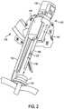
- FIG. 2illustrates another embodiment of a robotic arm 1120 and a tool assembly 1130 releasably coupled to the robotic arm 1120 .
- the robotic arm 1120can support and move the associated tool assembly 1130 along one or more mechanical degrees of freedom (e.g., all six Cartesian degrees of freedom, five or fewer Cartesian degrees of freedom, etc.).
- the robotic arm 1120includes a tool driver 1140 at a distal end of the robotic arm 1120 , which can assist with controlling features associated with the tool assembly 1130 .
- the robotic arm 1120also include a tool guide 1132 that couples to a trocar T that is mated to a distal end feature 1133 (e.g., a ring) of the tool guide 1132 .
- the tool guide 1130holds the trocar to allow the shaft of the tool assembly 1130 , which extends generally parallel to a threaded shaft of the tool guide 1132 , to be advanced through and retracted from the trocar.
- the tool driver 1140generally includes one or more motors, e.g., seven motors, that control a variety of movements and actions associated with the tool assembly 1130 .
- Each motorcan be configured to couple to a drive assembly in the tool driver to thereby cause movement of a corresponding actuator, which in turn actuates the end effector.
- actuation of one of the motorscan rotate one or more gear assemblies, which in turn can cause linear and/or rotational movement of at least one actuator (e.g., gears, cables) extending through the tool shaft.
- Each actuatorcan cause actuation of the end effector, e.g., clamping, firing, rotating, articulation, etc.
- the tool assembly 1130can be loaded from a top side of the driver 1140 with the shaft of the tool assembly 1130 being positioned in a shaft-receiving channel 1144 formed along the side of the driver 1140 .
- the shaft-receiving channel 1144allows the shaft, which extends along a central axis of the tool assembly 1130 , to extend along a central axis of the driver 1140 when the tool assembly 1130 is coupled to the driver 1140 .
- the shaftcan extend through on opening in the tool driver 1140 , or the two components can mate in various other configurations.
- the tool assembly 1130includes a housing 1135 coupled to a proximal end of a shaft 1136 and an end effector 1138 coupled to a distal end of the shaft 1136 .
- the housing 1135can include coupling features that assist with releasably coupling the housing 1135 to the tool driver 1140 of the robotic arm 1120 .
- the housing 1135can include drivers (e.g., gears, shafts, cables etc.) that can be directly or indirectly actuated by the one or more motors in the tool driver.
- Each driving member in the housing 1135can cause rotation or translation of an actuator (e.g., shaft, cable) extending through the elongate shaft and coupled to the end effector.
- Movement of the actuatorscan control the operation of various features associated with the end effector 1138 (e.g., clamping, firing, rotation, articulation, etc.), as well as control the movement of the shaft 1136 (e.g., rotation and/or articulation of the shaft).
- the shaft 1136can be releasably coupled to the housing 1135 such that the shaft 1136 can be interchangeable with other shafts. This can allow a single housing 1135 to be adaptable to various shafts 1136 having different end effectors 1138 .
- the shaft 1136can also include one or more joints or wrists 1137 that allow a part of the shaft 1136 or the end effector 1138 to rotate and/or articulate relative to the longitudinal axis of the shaft 1136 . This can allow for fine movements and various angulation of the end effector 1138 relative to the longitudinal axis of the shaft 1136 .
- the end effector 1138can include any of a variety of surgical tools, such as a stapler, a clip applier, forceps, a needle driver, a cautery device, a cutting tool, a pair of jaws, an imaging device (e.g., an endoscope or ultrasound probe), or a combined device that includes a combination of two or more various tools.
- surgical toolssuch as a stapler, a clip applier, forceps, a needle driver, a cautery device, a cutting tool, a pair of jaws, an imaging device (e.g., an endoscope or ultrasound probe), or a combined device that includes a combination of two or more various tools.
- FIG. 3illustrates a portion of the housing 1135 coupled to a portion of the driver 1140 with the motors being configured to drive the drivers in the housing 1135 .
- the tool driver 1140has a first motor (not shown) that drives rotation of a lead screw L 1 , which in turn causing an actuator A 1 , which is threadably coupled to lead screw L 1 , to linearly advance in the proximal direction (towards and into the housing 1135 ).
- Actuator A 1can include an extension threadably coupled to the lead screw L 1 .
- the extensioncan be coupled to or integrated with a partial cylindrical shaft that extends along the longitudinal axis of the tool housing 1135 and the tool driver 1140 .
- the partial cylindrical shaft of the actuator A 1can engage with driving member D 1 such that when the actuator A 1 is linearly advanced, the driving member D 1 is caused to linearly advance in the same direction.
- Driving member D 1can be coupled to an actuator extending through the tool shaft, such as cable C 1 , such that when driving member D 1 is advanced in the proximal direction, cable C 1 is pulled in the proximal direction.
- Cable C 1extends along the shaft of the tool assembly 1130 and is operatively coupled to a part of the end effector 1138 thereby controlling a function of the end effector 1138 (e.g., opening and closing of jaws, articulation, firing of one or more staples, etc.) when the cable is C 1 translated in either the proximal or distal direction.
- actuators in the tool driver and in the tool shaftare described as being linearly translated, the actuators can be linearly translated and/or rotationally moved as a result of actuation of a respective motor. Any number of motors can be included in the driver 1140 for actuating various aspects of the tool assembly 1130 .
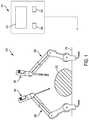
- FIGS. 4-6illustrate a bailout assembly 2000 mounted to a proximal end of a tool housing, which can have the same configuration as tool housing 1135 of FIGS. 2-3 .
- the tool housingincludes actuation members or actuators, e.g., cables 2006 , 2008 (similar to cable C 1 of FIG. 3 ) that extend through the elongate shaft and couple to a feature associated with either the shaft 2010 or an end effector disposed on a distal end thereof, the cables 2006 , 2008 to thereby control operation of various features associated with the shaft 2010 and/or an end effector.
- a proximal end of each cable 2006 , 2008is coupled to a driving member or driver 2002 , 2004 (similar to the driver D 1 of FIG. 3 ).
- the drivers 2002 , 2004can each be engaged with an actuator of the tool driver (such as actuator A 1 of FIG. 3 ) such that actuation of a motor causes actuation of the drivers 2002 , 2004 .
- an actuator of the tool driversuch as actuator A 1 of FIG. 3
- actuation of a motorcauses actuation of the drivers 2002 , 2004 .
- proximal end of each driving member 2002 , 2004being coupled to a proximal end of a cable 2006 , 2008
- proximal movement of the driving members 2002 , 2004pulls the cable 2006 , 2008 coupled thereto proximally, to thereby actuate the end effector.
- the cables 2006 , 2008can be articulation cables that are coupled to opposite sides of the end effector adjacent to a pivot joint or wrist.
- Proximal movement of one of the cables 2006will cause the end effector to articulate in a first direction, and proximal movement of the other cable 2008 will cause the end effector to articulate in a second, opposite direction.
- the cables 2006 , 2008can control articulation in a single plane.
- the devicecan include any number of articulation cables for causing articulation in any number of directions.
- the actuation memberscan have a variety of other configurations and can be used to affect any number of different motions of the end effector and/or shaft.
- one of the actuation memberscan be coupled to a jaw of an end effector and proximal translation of the actuation member can be configured to pull the jaw from the open position to the closed position.
- the bailout mechanism 2000is mounted on the tool housing and includes a housing 2001 having one or more bailout levers in the form of crank arms 2018 coupled thereto.
- the devicecan include any number of bailout levers, and the number of levers will depend on the number of actuators in which mechanical bailout may be decided.
- Each bailout lever 2018is configured to apply a direct force to an actuator extending through the tool shaft to thereby pull the actuator proximally, thus manually retracting the actuator and reversing a motion of the end effector.
- the actuatoris an articulation cable
- the bailout leverwill be effective to retract the cable and return the end effector to a straight, non-articulated configuration.
- the bailout leverwill be effective to retractor the drive shaft and thereby pull the sled back to the initial position.
- the actuatoris a closure tube that advances to close opposed jaws of an end effector
- the bailout leverwill be effective to retractor the closure tube thereby allowing the jaws to open.
- the bailout levercan be used for any number of actuation assemblies.
- the bailout assembly 2000includes longitudinally slidable side walls 2012 disposed on opposite sides of the housing 2001 .
- the side walls 2012can be longitudinally slidably coupled to the housing 2001 by any number of mechanisms, such as grooves, channels, edging, tabs, etc.
- a first pawl 2014is rotatably disposed on a proximal end of each of the slidable side walls 2012 .
- Each of the first pawls 2014engages a rotatable wheel or gear 2016 disposed within the housing 2001 adjacent to the proximal end of the tool housing 2010 .
- the gears 2016are each only rotatable in one direction, e.g.
- the crank arms 2018have a home position illustrated in FIG. 4 where each crank arm 2018 is approximately parallel to a longitudinal axis of the shaft 2010 , an outward position illustrated in FIG. 5 where the crank arm 2018 is rotated to an approximately perpendicular position away from the shaft 2010 , and an inward position illustrated in FIG. 6 where the crank arm 2018 is rotated toward the shaft 2010 .
- Bailout cables 2022are coupled on a proximal end thereof to the gears 2018 and are each wound around the gears 2018 .
- the bailout cables 2022extend distally into the tool housing 2010 through an opening in a proximal end of the tool housing 2010 and are coupled on a distal end thereof to bailout plates 2024 that in turn couple to the proximal end of one of the cables 2006 , 2008 .
- the bailout cables 2022cross each other such that they extend from the gears 2018 to an opposite side of the longitudinal axis of the shaft 2010 to mate to the bailout plates 2024 .
- the bailout plates 2024extend along a proximal surface of each of the driving members 2002 , 2004 prior to activation of the bailing assembly.
- the bailout cables 2022are configured to translate linearly along the longitudinal axis of the shaft 2010 .
- the bailout plates 2024 of the bailout cables 2022are non-removably coupled to each of the cables 2006 , 2008 .
- the cables 2006 , 2008can pass through a hole in the plates 2024 and can include a bulge 2006 a , 2008 a on a proximal end thereof that is too large to pass through the hole.
- a variety of coupling meansare possible, such as crimping, tying, pressing, welding, etc.
- each driving member 2002 , 2004is removably coupled to the proximal end of each cable 2006 , 2008 .
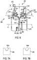
- the proximal end of each driving member 2002 , 2004can include a u-shaped notch 2002 a , 2004 a , as illustrated in FIGS. 7 a and 7 b .
- Each cable 2006 , 2008can be positioned within the u-shaped notch 2002 a , 2004 a with each corresponding bailout plate 2024 resting on top of the proximal ends of each driving member 2002 , 2004 during normal operation of the device.
- LED lights 2026can be disposed at a distal end of the bailout mechanism 2000 , and each LED light 2026 can be electronically coupled to the device.
- the LED lights 2026can be coupled to a control system, such as the control system 315 discussed herein.
- the LED lightscan be configured to indicate a status of the driving members 2002 , 2004 .
- the LED lights 2026can be configured to blink or otherwise indicate a location of the failure and/or error. Error locations can be identified in a variety of ways, as further explained in U.S. patent application Ser. No. 15/131,963, filed on Apr. 18, 2016 and entitled “Method for Operating a Surgical Instrument,” which is hereby incorporated herein by reference in its entirety.
- the driving members 2002 , 2004can translate linearly to manipulate the cables 2002 , 2004 , thereby actuating the end effector.
- the bailout cables 2022have enough slack to translate with the driving members 2002 , 2004 and the cables 2002 , 2004 .
- driving member 2002 and actuation cable 2006are advanced distally from a home position H 1 while driving member 2004 and actuation cable 2008 are retracted proximally from the home position F 11 , for example while performing articulation of the shaft 2010 .
- the bailout cables 2022move distally and proximally with the corresponding driving members 2002 , 2004 and cables 2006 , 2008 .
- the bailout mechanism 2000can be used to bailout the device.
- the crank arm 2018can be repeatedly rotated to the outward position to cause the second pawl 2020 coupled thereto to rotate the gear 2016 , e.g., in the clockwise direction.
- Turning the gear 2016causes the bailout cable 2022 to wind around the gear and thereby retract proximally. This will in turn apply a proximal force to the bailout plate 2024 , causing an end of the plate 2024 (opposite to the end having the bailout cable 2022 attached thereto) to be pulled upward such that the plate 2024 pivots, as shown in FIG. 5 .
- the gear 2016can either be released to free a retracted cable, or rotated to retract an advanced cable.
- the crank arm 2018 coupled theretocan be rotated toward the shaft 2010 into the inward position, as shown in FIG. 6 , to cause the second pawl 2020 to disengage from the gear 2016 .
- the side wall 2012can be manually moved proximally, disengaging the first pawl 2014 from the gear 2016 .
- the crank arm 2018 coupled theretocan then be repeatedly rotated toward the shaft 2010 to rotate the gear 2016 and wind up the bailout cable 202 , thereby pulling the advanced actuation cable 2006 coupled thereto back to the home position.
- the pawls 2014 , 2020will work in unison to prevent the gear 2016 from rotating in an opposite direction.
- the corresponding LED light 2026can indicate when each cable 2006 , 2008 is in the home position. Accordingly, the bailout assembly allows an actuator to be disengaged from the drive assembly and to be directly manually retracted.
- FIG. 8illustrates another embodiment of a bailout mechanism 3000 coupled to a tool housing 3001
- FIG. 9illustrates a similar bailout mechanism 4000 coupled to a tool housing 4001
- the tool housings 3001 , 4001can be similar to the tool housing 1135 of FIGS. 2-3
- the tool housing 3001includes drive assemblies disposed therein and configured to couple to one or more motors in the tool driver (e.g., tool driver 1140 of FIG. 2 ). In the illustrated embodiment, there are seven drive assemblies (only two are shown) that couple to several motors in the tool driver.
- Each drive assemblyis configured to control an actuation member extending through the elongate shaft for actuating the end effector and/or the shaft, e.g., for causing rotation, articulation, clamping, firing, etc.
- the tool housingcan include any number of drive assemblies, and the number may vary depending on the particular tool and the actuation members needed to operate the end effector.
- a first drive assembly 3004includes a coupling 3004 d for connecting to a motor M 1 .
- a second drive assembly 3046includes a coupling 3046 d for connecting to a lead screw L 2 .
- the bailout mechanism 3000there are two bailouts illustrated, one for the first drive assembly 3004 with a drive shaft 3004 s and the other for the second drive assembly 3046 with a drive shaft 3046 s . Separate bailouts can be provided for each function (e.g. clamping, firing, rotation, actuation, etc.), and the two illustrated bailouts are exemplary bailouts that can be applied to any or all drive assemblies.
- the bailout mechanism 3000has a removable cover 3020 and an inner cover 3022 .
- a hand crank 3024Extending through a proximal surface of the inner cover 3022 is a hand crank 3024 .
- the hand crank 3024engages a gear which engages a first primary bailout drive gear 3026 , which in turn is non-removably coupled to a second primary bailout drive gear 3028 by a drive shaft 3027 .
- rotation of the hand crank 3024ultimately causes rotation of the second primary bailout drive gear 3028 .
- a spur gear 3030is located on a proximal end of the drive shaft 3004 s .
- a bailout switch 3032extends through the inner cover 3022 and is coupled to the drive shaft 3004 s .
- the bailout switch 3032is longitudinally slidably disposed within grooves formed in the cover 3022 .
- the switch 3032couples to the drive shaft 3004 s by a perpendicular extension 3032 p that extends between the cover 3022 and the drive shaft 3004 s .
- the perpendicular extension 3032 p of the switch 3032has a notch 3032 n on an end thereof through which the drive shaft 3004 s passes.
- the drive shaft 3004 shas a circular portion 3004 c with a diameter greater than the rest of the drive shaft 3004 s and greater than a diameter of the notch 3032 n of the switch 3032 such that the circular portion 3004 c engages and rests distally to the perpendicular extension 3032 p of the switch 3032 .
- An LED light 3033can be disposed on the inner cover 3022 adjacent to the bailout switch 3032 through a variety of means, such as gluing, screwing, or embedding by compression fit the LED light 3033 through a hole in the cover 3022 .
- the LED light 3033can be coupled to a control system, such as the control system 315 discussed herein.
- a gear 3034is fixed on the drive shaft 3004 s and has teeth thereon that engage an actuator 3010 that extends through a shaft 3040 and that can actuate various features associated with the shaft 3040 and/or an end effector that can be disposed on a distal end of the shaft 3040 , similar to a functionality of the cable C 1 of FIG. 3 .
- a spring 3036is disposed on a distal end of the drive shaft 3004 s , and the drive shaft 3004 s couples to the motor M 1 at a distalmost end thereof through the coupling 3004 d .
- a tooth on the motor M 1engages a groove on the coupling 3004 d .
- the spring 3036biases the drive shaft 3004 s proximally.
- the spring 3036is kept in a compressed state, and the bailout switch 3032 is configured to apply distal pressure to the drive shaft 3004 s to keep the drive shaft 3004 s engaged with the motor M 1 .
- the drive shaft 3004 swill rotate with rotation of the motor M 1 , which will cause rotation of the gear 3034 and subsequently cause driving of the actuator 3010 through one or more additional gears.
- the switch 3032applies distal pressure by the perpendicular extension 3032 p and the notch 3032 n of the switch 3032 applying distal force to the circular portion 3004 c on the drive shaft 3004 s .
- the LED light 3033can indicate a normal status of the bailout switch 3032 (i.e.
- the switch 3032When bailout is desired, the switch 3032 is actuated by manually sliding the switch 3032 proximally.
- the perpendicular extension 3032 p and the notch 3032 n of the switch 3032will slide proximally, which will allow the circular portion 3004 c on the drive shaft 3004 s to move proximally because the spring 3036 will force the drive shaft 3004 s proximally as the spring 3036 decompresses and biases the drive shaft 3004 s proximally.
- Proximal movement of the drive shaft 3004 smoves the coupling 3004 d out of engagement with the motor M 1 . So any further rotation of the motor M 1 will no longer rotate the drive shaft 3004 s .
- the gear 3034 on the drive shaft 3004 swill remain engaged with the actuator 3010 even with proximal movement because the gear 3034 is generally elongate in length such that the teeth of the gear 3034 will move proximally along the actuator 3010 while remaining engaged therewith.
- the spur gear 3030will move proximally with the drive shaft 3004 s , bringing the spur gear 3030 into engagement with the second primary bailout drive gear 3028 .
- the bailout hand crank 3024can then be manually rotated to apply rotational movement to the first primary bailout drive gear 3026 , which will rotate the drive shaft 3027 and the second primary bailout drive gear 3028 .
- the second primary bailout drive gear 3028will in turn rotate the spur gear 3030 .
- Rotation of the spur gear 3030will rotate the drive shaft 3004 s , which will rotate the gear 3034 .
- the gear 3034will rotate the actuator 3010 and subsequently cause retraction and/or reversal of various features associated with the shaft 3040 and/or the end effector that can be disposed on the distal end of the shaft 3040 , similar to the functionality of the cable C 1 of FIG. 3 .
- rotation of the drive shaft 3004 scan cause reversal through bailout of actuators driven by a motor and responsible for a variety of functions, such as cutting and/or grasping tissue.
- the LED light 3033can optionally be used to indicate an error status of the bailout switch 3032 (i.e.
- a top bailout rod 3048is disposed in the inner cover 3022 directly proximal to a bottom bailout rod 3046 s .
- a spur gear 3050On a proximal end of the top bailout rod 3048 is a spur gear 3050 .
- a spring 3051is disposed on the bailout rod 3048 .
- a bailout switch 3052is coupled to the top bailout rod 3048 and is configured to apply a proximal force on the top bailout rod 3048 .
- the bailout switch 3052extends through the inner cover 3022 .
- the bailout switch 3052is longitudinally slidably disposed within a groove formed in the cover 3022 .
- the switch 3052couples to the top bailout rod 3048 by a perpendicular extension 3052 p that extends between the cover 3022 and the top bailout rod 3048 .
- the perpendicular extension 3052 p of the switch 3052has a notch 3052 n on an end thereof through which the top bailout rod 3048 passes.
- the top bailout rod 3048has a circular portion 3048 c with a diameter greater than the rest of the top bailout rod 3048 and greater than a diameter of the notch 3052 n of the switch 3052 such that the circular portion 3048 c engages and rests proximally to the perpendicular extension 3052 p of the switch 3052 .
- An LED light 3053can be disposed on the inner cover 3022 adjacent to the bailout switch 3052 through a variety of means, such as gluing, screwing, or embedding by compression fit the LED light 3053 through a hole in the cover 3022 .
- the LED light 3053can be coupled to a control system, such as the control system 315 discussed herein.
- the top bailout rod 3048has a coupling mechanism 3048 m in the form of a groove on a distal end thereof that is configured to engage a coupling mechanism 3046 t in the form of a tooth on a proximal end of the bottom bailout rod 3046 s .
- the coupling 3046 d in the form of a groove on a distalmost end of the bottom bailout rod 3046 sis configured to engage a tooth of the lead screw L 2 .
- the spring 3051is kept in a compressed state, and the bailout switch 3052 is configured to apply proximal pressure to the circular portion 3048 c of the top bailout rod 3048 to keep the spur gear 3050 held proximally and thus disengaged from the second primary bailout drive gear 3028 .
- the top bailout rod 3048held proximally by the bailout switch 3052 , the top bailout rod 3048 is disengaged with the bottom bailout rod 3046 s , and the bottom bailout rod 3046 s is disengaged from the lead screw L 2 .
- the switch 3052When bailout is desired, the switch 3052 is actuated by manually sliding the switch 3052 distally.
- the perpendicular extension 3052 p and the notch 3052 n of the switch 3052will move distally, which will allow the circular portion 3048 c of the top bailout rod 3048 to move distally because the spring 3056 will force the top bailout rod 3048 distally as the spring 3056 decompresses and biases the top bailout rod 3048 distally.
- Distal movement of the top bailout rod 3048moves the coupling mechanism 3048 m distally into engagement with the coupling mechanism 3046 t of the bottom bailout rod 3046 s while forcing the bottom bailout rod 3046 s distally itself.
- the coupling 3046 d on the distalmost end of the bottom bailout rod 3046 sis then brought into engagement with the lead screw L 2 as the bottom bailout rod 3046 s moves distally.
- the spur gear 3050will thus move distally with the top bailout rod 3048 , bringing the spur gear 3050 into engagement with the second primary bailout drive gear 3028 .
- the bailout hand crank 3024can then be manually rotated to apply rotational movement to the first primary bailout drive gear 3026 , which will rotate the drive shaft 3027 and the second primary bailout drive gear 3028 .
- the second primary bailout drive gear 3028will in turn rotate the spur gear 3050 .
- a lead screwcan cause linear and/or rotational movement of at least one actuator responsible for controlling one or more actions and movements, such as articulation, which can be reversed through bailout.
- the LED light 3053can optionally be used to indicate an error status of the bailout switch 3052 (i.e.
- FIG. 9further illustrates a hand crank 4010 , a removable outer cover 4012 , an inner cover 4014 , and LED lights 4016 similar to the bailout mechanism 3000 of FIG. 8 , and the bailout mechanism 4000 can operate similar to the bailout mechanism 3000 of FIG. 8 .
- the bailout mechanisms 3000 , 4000are selective bailout mechanisms, allowing individual actuators to be bailed out. Thus select features and functions of any shaft and/or any end effector disposed on a distal end of the shaft can be reversed, retracted, and/or bailed out.
- FIGS. 10-13illustrate additional embodiments of bailout mechanism 5000 , 6000 , and 7000 .
- the bailout mechanisms 5000 , 6000 , and 7000can be coupled to a tool housing actuation assembly, such as the tool housing actuation assembly contained within the housing 1135 of FIGS. 2-3 .
- the bailout mechanisms 5000 , 6000 , and 7000are similar to the bailout mechanisms 3000 , 4000 of FIGS. 8-9 but provide single-actuator (and often single-function) bailout mechanisms rather than allowing selection of actuator(s) as in the bailout mechanisms 3000 , 4000 .
- FIG. 10illustrates a bailout mechanism 5000 on a tool housing 5001 with an elongate shaft 5003 and a bailout lever 5002 coupled to a large motor 5004 and an actuator 5006 .
- the motor 5004has gear teeth that engage with a gear 5006 g attached to a proximal end of the actuator 5006 .
- the bailout lever 5002has two positions, a first position in which the lever 5002 is held in a recessed part of a housing 5001 c of the tool housing 5001 and a second position in which the lever 5002 is pivoted away from the housing 5001 c about a pivot 5002 p .
- the lever 5002passes through the housing 5001 c of the tool housing 5001 and has a ratchet and gear mechanism 5002 g with teeth that engage the gear 5006 g upon pivoting the lever 5002 into the second position.
- the lever 5002is configured to be pivoted back and forth about the pivot 5002 p to provide rotation to the gear 5006 g .
- the lever 5002is in the first position recessed in the housing 5001 c .
- the motor 5004can be driven, which will thus rotate the gear 5006 g and the actuator 5006 and cause actuation of a function on a distal end of the elongate shaft 5003 and/or an end effector (not shown) on a distal end of the elongate shaft 5003 .
- the bailout lever 5002can be pivoted into the second position. Manually pivoting the bailout lever 5002 will cause the ratchet and gear mechanism 5002 g to rotate the gear 5006 g , thus rotating and reversing the actuator 5006 .
- the functionality actuated by the actuator 5006is thus reversed as long as a user continues to pivot the bailout lever 5002 .
- the bailout mechanism 6000 of FIG. 11is on a tool housing 6001 and is similar to the bailout mechanism 5000 of FIG. 10 , containing a bailout lever 6002 and a plurality of actuators 6004 .
- the bailout lever 6002under normal operation the bailout lever 6002 is recessed in a housing 6001 c of the tool housing 6001 and a motor and gear combination (not shown but similar to that of FIG. 10 ) rotate the actuators 6004 to perform various functions on an elongate shaft (not shown) and/or an end effector (not shown).
- the bailout lever 6002is manually pivoted away from the housing 6001 c .
- a ratchet and gear mechanism(not shown but similar to that of FIG. 10 ) rotates one of the actuators 6004 , causing the one or more functions of the actuator 6004 to be reversed.
- the bailout mechanism 7000 of FIG. 12is on a tool housing 7001 and is similar to the bailout mechanisms 5000 , 6000 , containing a bailout lever 7003 and a plurality of drivers 7010 a .
- a tool 7002is configured to be received in a channel 7001 d of the tool housing 7001 .
- the tool 7002has actuators 7010 b configured to engage the drivers 7010 a through a groove and tooth engagement and configured to perform various functions on an elongate shaft 7012 and/or an end effector (not shown) on a distal end of the elongate shaft 7012 .
- An alignment feature 7004can be formed in the tool housing 7001 and configured to mate with a corresponding alignment feature 7006 on the tool 7002 that is configured to be mated with the tool housing 7001 and has a coupling ring 7008 and a shaft 7012 on a distal end thereof.
- the bailout lever 7002is recessed in a housing 7001 c of the tool housing 7001 and a motor and gear combination (not shown but similar to that of FIG. 10 ) rotate the drivers 7010 a , which rotate the actuators 7010 b to perform various functions on the elongate shaft 7012 and/or the end effector.
- the bailout lever 7002is manually pivoted away from the housing 7001 c .
- a ratchet and gear mechanism(not shown but similar to that of FIG. 10 ) rotates one of the drivers 7010 a , which rotates one of the actuators 7010 b and causes the one or more functions of the one actuator 7010 b to be reversed.
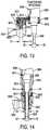
- FIG. 13illustrates a lateral adapter 8000 .
- a robotic arm 8002(similar to the robotic arm 1120 ) and a tool assembly 8004 (similar to the tool assembly 1130 ) are provided, but the robotic arm 8002 and the tool assembly 8004 cannot be releasably coupled together under normal circumstances.
- the tool assembly 8004has an elongate shaft 8006 with a head having a distal diameter X 3 .
- the robotic arm 8002has an opening 8003 configured to receive a shaft of a tool assembly with a maximum diameter X 1 , which is less than X 3 .
- the lateral adapter 8000is thus provided having a receiving portion 8020 configured to receive the tool assembly 8004 at a location displaced laterally from an extension portion 8022 of the adapter 8000 that is configured to couple to and extend at least partially through the opening 8003 of the robotic arm 8002 .
- the robotic armhas cables 8010 that couple at a contact point 8012 to cables 8011 in the adapter 8000 , which in turn couple at a contact point 8014 to cables 8008 within the tool assembly 8004 .
- Any control signals and/or powercan travel between the robotic arm 8002 and the tool assembly 8004 along the cables 8008 , 8010 , 8011 .
- a sterile barrier 8030can be provided between the robotic arm 8002 on one side and the adapter 8000 and the tool assembly 8004 on another side in order to provide a sterile operation area while using the surgical system.
- the lateral adapter 8000may allow the tool assembly 8004 and the robotic arm 8002 to couple together even though, as discussed, the robotic arm 8002 and the tool assembly 8004 cannot be releasably coupled together by passing the tool assembly 8004 through the robotic arm 8002 .
- FIG. 14illustrates another embodiment of an adaptor.
- the adaptoris a vertical adapter 9000 , rather than a lateral adapter.
- a tool assembly 9004has an elongate shaft 9006 with a head having a distal diameter X 2 and a body having a diameter X 5 .
- a robotic arm 9002(similar to the robotic arm 8002 ) has an opening 9003 configured to receive a shaft of a tool assembly with a maximum diameter X 4 .
- the adapter 9000has a receiving portion 9020 configured to receive the tool assembly 9004 .
- the receiving portion 9020is displaced vertically from an extension portion 9022 of the adapter 9000 that is configured to couple to and extend at least partially through the opening 9003 of the robotic arm 9002 .
- the robotic armhas cables 9010 that couple at a contact point 9012 to cables 9011 in the adapter 9000 that in turn couple at a contact point 9014 to cables 9008 within the tool assembly 9004 .
- Any control signals and/or powercan travel between the robotic arm 9002 and the tool assembly 9004 along the cables 9008 , 9010 , 9011 .
- a sterile barrier 9030can be provided between the robotic arm 9002 on one side and the adapter 9000 and the tool assembly 9004 on another side in order to provide a sterile operation area while using the surgical system.
- the diameter X 2 of the head of the tool assembly 9004can be less than the diameter X 4 of the opening 9003 of the robotic arm 9002 , thus allowing the head of the tool assembly 9004 to pass through the opening 9003 of the robotic arm 9002 .
- the diameter X 5 of the body of the tool assembly 9004is greater than the diameter X 4 , however, thus preventing the tool assembly 9004 from fully engaging with the robotic arm 9002 .
- the vertical adapter 9000may consequently allow the tool assembly 9004 and the robotic arm 9002 to couple together even though, as provided, the robotic arm 9002 and the tool assembly 9004 cannot be releasbly coupled together by sitting the tool assembly 8004 fully into the opening 9003 of the robotic arm 9002 .
- an end effectoris the part of a surgical instrument or assembly that performs a specific surgical function, e.g., forceps/graspers, needle drivers, scissors, electrocautery hooks, staplers, clip appliers/removers, suction tools, irrigation tools, etc. Any end effector can be utilized with the surgical systems described herein. Further, in exemplary embodiments, an end effector can be configured to be manipulated by a user input tool.
- the input toolcan be any tool that allows successful manipulation of the end effector, whether it be a tool similar in shape and style to the end effector, such as an input tool of scissors similar to end effector scissors, or a tool that is different in shape and style to the end effector, such as an input tool of a glove dissimilar to end effector graspers, and such as an input tool of a joystick dissimilar to end effector graspers.
- the input toolcan be a larger scaled version of the end effector to facilitate ease of use.
- Such a larger scale input toolcan have finger loops or grips of a size suitable for a user to hold.
- the end effector and the input toolcan have any relative size.
- a slave tool, e.g., a surgical instrument, of the surgical systemcan be positioned inside a patient's body cavity through an access point in a tissue surface for minimally invasive surgical procedures.
- cannulassuch as trocars are used to provide a pathway through a tissue surface and/or to prevent a surgical instrument or guide tube from rubbing on patient tissue.
- Cannulascan be used for both incisions and natural orifices.
- Some surgical proceduresrequire insufflation, and the cannula can include one or more seals to prevent excess insufflation gas leakage past the instrument or guide tube.
- the cannulacan have a housing coupled thereto with two or more sealed ports for receiving various types of instruments besides the slave assembly.
- any of the surgical system components disclosed hereincan have a functional seal disposed thereon, therein, and/or therearound to prevent and/or reduce insufflation leakage while any portion of the surgical system is disposed through a surgical access port, such as a cannula.
- the surgical systemscan also be used in open surgical procedures.
- a surgical access pointis a point at which the slave tool enters a body cavity through a tissue surface, whether through a cannula in a minimally invasive procedure or through an incision in an open procedure.
- the systems, devices, and methods disclosed hereincan be implemented using one or more computer systems, which may also be referred to herein as digital data processing systems and programmable systems.
- One or more aspects or features of the subject matter described hereincan be realized in digital electronic circuitry, integrated circuitry, specially designed application specific integrated circuits (ASICs), field programmable gate arrays (FPGAs) computer hardware, firmware, software, and/or combinations thereof.
- ASICsapplication specific integrated circuits
- FPGAsfield programmable gate arrays
- These various aspects or featurescan include implementation in one or more computer programs that are executable and/or interpretable on a programmable system including at least one programmable processor, which can be special or general purpose, coupled to receive data and instructions from, and to transmit data and instructions to, a storage system, at least one input device, and at least one output device.
- the programmable system or computer systemmay include clients and servers.
- a client and serverare generally remote from each other and typically interact through a communication network. The relationship of client and server arises by virtue of computer programs running on the respective computers and having a client-server relationship to each other.
- the computer programswhich can also be referred to as programs, software, software applications, applications, components, or code, include machine instructions for a programmable processor, and can be implemented in a high-level procedural language, an object-oriented programming language, a functional programming language, a logical programming language, and/or in assembly/machine language.
- machine-readable mediumrefers to any computer program product, apparatus and/or device, such as for example magnetic discs, optical disks, memory, and Programmable Logic Devices (PLDs), used to provide machine instructions and/or data to a programmable processor, including a machine-readable medium that receives machine instructions as a machine-readable signal.
- machine-readable signalrefers to any signal used to provide machine instructions and/or data to a programmable processor.
- the machine-readable mediumcan store such machine instructions non-transitorily, such as for example as would a non-transient solid-state memory or a magnetic hard drive or any equivalent storage medium.
- the machine-readable mediumcan alternatively or additionally store such machine instructions in a transient manner, such as for example as would a processor cache or other random access memory associated with one or more physical processor cores.
- one or more aspects or features of the subject matter described hereincan be implemented on a computer having a display device, such as for example a cathode ray tube (CRT) or a liquid crystal display (LCD) or a light emitting diode (LED) monitor for displaying information to the user and a keyboard and a pointing device, e.g., a mouse, a trackball, etc., by which the user may provide input to the computer.
- a display devicesuch as for example a cathode ray tube (CRT) or a liquid crystal display (LCD) or a light emitting diode (LED) monitor for displaying information to the user and a keyboard and a pointing device, e.g., a mouse, a trackball, etc.
- CTRcathode ray tube
- LCDliquid crystal display
- LEDlight emitting diode
- a keyboard and a pointing devicee.g., a mouse, a trackball, etc.
- Other kinds of devices
- feedback provided to the usercan be any form of sensory feedback, such as for example visual feedback, auditory feedback, or tactile feedback; and input from the user may be received in any form, including, but not limited to, acoustic, speech, or tactile input.
- Other possible input devicesinclude, but are not limited to, touch screens or other touch-sensitive devices such as single or multi-point resistive or capacitive trackpads, voice recognition hardware and software, optical scanners, optical pointers, digital image capture devices and associated interpretation software, and the like.
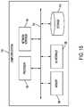
- FIG. 15illustrates one exemplary embodiment of a computer system 100 .
- the computer system 100includes one or more processors 102 which can control the operation of the computer system 100 .
- processorsare also referred to herein as “controllers.”
- the processor(s) 102can include any type of microprocessor or central processing unit (CPU), including programmable general-purpose or special-purpose microprocessors and/or any one of a variety of proprietary or commercially available single or multi-processor systems.
- the computer system 100can also include one or more memories 104 , which can provide temporary storage for code to be executed by the processor(s) 102 or for data acquired from one or more users, storage devices, and/or databases.
- the memory 104can include read-only memory (ROM), flash memory, one or more varieties of random access memory (RAM) (e.g., static RAM (SRAM), dynamic RAM (DRAM), or synchronous DRAM (SDRAM)), and/or a combination of memory technologies.
- ROMread-only memory
- flash memoryone or more varieties of random access memory (RAM) (e.g., static RAM (SRAM), dynamic RAM (DRAM), or synchronous DRAM (SDRAM)), and/or a combination of memory technologies.
- RAMrandom access memory
- SRAMstatic RAM
- DRAMdynamic RAM
- SDRAMsynchronous DRAM
- the various elements of the computer system 100can be coupled to a bus system 112 .
- the illustrated bus system 112is an abstraction that represents any one or more separate physical busses, communication lines/interfaces, and/or multi-drop or point-to-point connections, connected by appropriate bridges, adapters, and/or controllers.
- the computer system 100can also include one or more network interface(s) 106 , one or more input/output (TO) interface(s) 108 , and one or more storage device(s) 110 .
- TOinput/output
- the network interface(s) 106can enable the computer system 100 to communicate with remote devices, e.g., other computer systems, over a network, and can be, for non-limiting example, remote desktop connection interfaces, Ethernet adapters, and/or other local area network (LAN) adapters.
- the TO interface(s) 108can include one or more interface components to connect the computer system 100 with other electronic equipment.
- the TO interface(s) 108can include high speed data ports, such as universal serial bus (USB) ports, 1394 ports, Wi-Fi, Bluetooth, etc.
- the computer system 100can be accessible to a human user, and thus the TO interface(s) 108 can include displays, speakers, keyboards, pointing devices, and/or various other video, audio, or alphanumeric interfaces.
- the storage device(s) 110can include any conventional medium for storing data in a non-volatile and/or non-transient manner. The storage device(s) 110 can thus hold data and/or instructions in a persistent state, i.e., the value(s) are retained despite interruption of power to the computer system 100 .
- the storage device(s) 110can include one or more hard disk drives, flash drives, USB drives, optical drives, various media cards, diskettes, compact discs, and/or any combination thereof and can be directly connected to the computer system 100 or remotely connected thereto, such as over a network.
- the storage device(s)can include a tangible or non-transitory computer readable medium configured to store data, e.g., a hard disk drive, a flash drive, a USB drive, an optical drive, a media card, a diskette, a compact disc, etc.
- FIG. 15can be some or all of the elements of a single physical machine. In addition, not all of the illustrated elements need to be located on or in the same physical machine.
- Exemplary computer systemsinclude conventional desktop computers, workstations, minicomputers, laptop computers, tablet computers, personal digital assistants (PDAs), mobile phones, and the like.
- PDAspersonal digital assistants
- the computer system 100can include a web browser for retrieving web pages or other markup language streams, presenting those pages and/or streams (visually, aurally, or otherwise), executing scripts, controls and other code on those pages/streams, accepting user input with respect to those pages/streams (e.g., for purposes of completing input fields), issuing HyperText Transfer Protocol (HTTP) requests with respect to those pages/streams or otherwise (e.g., for submitting to a server information from the completed input fields), and so forth.
- the web pages or other markup languagecan be in HyperText Markup Language (HTML) or other conventional forms, including embedded Extensible Markup Language (XML), scripts, controls, and so forth.
- the computer system 100can also include a web server for generating and/or delivering the web pages to client computer systems.
- the computer system 100can be provided as a single unit, e.g., as a single server, as a single tower, contained within a single housing, etc.
- the single unitcan be modular such that various aspects thereof can be swapped in and out as needed for, e.g., upgrade, replacement, maintenance, etc., without interrupting functionality of any other aspects of the system.
- the single unitcan thus also be scalable with the ability to be added to as additional modules and/or additional functionality of existing modules are desired and/or improved upon.
- a computer systemcan also include any of a variety of other software and/or hardware components, including by way of non-limiting example, operating systems and database management systems. Although an exemplary computer system is depicted and described herein, it will be appreciated that this is for sake of generality and convenience. In other embodiments, the computer system may differ in architecture and operation from that shown and described here.
- the devices disclosed hereincan also be designed to be disposed of after a single use, or they can be designed to be used multiple times. In either case, however, the device can be reconditioned for reuse after at least one use. Reconditioning can include any combination of the steps of disassembly of the device, followed by cleaning or replacement of particular pieces and subsequent reassembly. In particular, the device can be disassembled, and any number of the particular pieces or parts of the device can be selectively replaced or removed in any combination. Upon cleaning and/or replacement of particular parts, the device can be reassembled for subsequent use either at a reconditioning facility, or by a surgical team immediately prior to a surgical procedure.
- reconditioning of a devicecan utilize a variety of techniques for disassembly, cleaning/replacement, and reassembly. Use of such techniques, and the resulting reconditioned device, are all within the scope of the present application.
- components of the invention described hereinwill be processed before use.
- a new or used instrumentis obtained and if necessary cleaned.
- the instrumentcan then be sterilized.
- the instrumentis placed in a closed and sealed container, such as a plastic or TYVEK bag.
- the container and instrumentare then placed in a field of radiation that can penetrate the container, such as gamma radiation, x-rays, or high energy electrons.
- the radiationkills bacteria on the instrument and in the container.
- the sterilized instrumentcan then be stored in the sterile container.
- the sealed containerkeeps the instrument sterile until it is opened in the medical facility.
- the deviceis sterilized. This can be done by any number of ways known to those skilled in the art including beta or gamma radiation, ethylene oxide, steam, and a liquid bath (e.g., cold soak).
- a liquid bathe.g., cold soak.
- An exemplary embodiment of sterilizing a device including internal circuitryis described in more detail in U.S. Pat. No. 8,114,345 filed Feb. 8, 2008 and entitled “System And Method Of Sterilizing An Implantable Medical Device.” It is preferred that device, if implanted, is hermetically sealed. This can be done by any number of ways known to those skilled in the art.
Landscapes
- Health & Medical Sciences (AREA)
- Engineering & Computer Science (AREA)
- Surgery (AREA)
- Life Sciences & Earth Sciences (AREA)
- Medical Informatics (AREA)
- Robotics (AREA)
- Biomedical Technology (AREA)
- Heart & Thoracic Surgery (AREA)
- Nuclear Medicine, Radiotherapy & Molecular Imaging (AREA)
- Molecular Biology (AREA)
- Animal Behavior & Ethology (AREA)
- General Health & Medical Sciences (AREA)
- Public Health (AREA)
- Veterinary Medicine (AREA)
- General Engineering & Computer Science (AREA)
- Surgical Instruments (AREA)
- Mechanical Engineering (AREA)
Abstract
Description
Claims (14)
Priority Applications (1)
| Application Number | Priority Date | Filing Date | Title |
|---|---|---|---|
| US15/238,219US10849698B2 (en) | 2016-08-16 | 2016-08-16 | Robotics tool bailouts |
Applications Claiming Priority (1)
| Application Number | Priority Date | Filing Date | Title |
|---|---|---|---|
| US15/238,219US10849698B2 (en) | 2016-08-16 | 2016-08-16 | Robotics tool bailouts |
Publications (2)
| Publication Number | Publication Date |
|---|---|
| US20180051780A1 US20180051780A1 (en) | 2018-02-22 |
| US10849698B2true US10849698B2 (en) | 2020-12-01 |
Family
ID=61191475
Family Applications (1)
| Application Number | Title | Priority Date | Filing Date |
|---|---|---|---|
| US15/238,219Active2039-01-08US10849698B2 (en) | 2016-08-16 | 2016-08-16 | Robotics tool bailouts |
Country Status (1)
| Country | Link |
|---|---|
| US (1) | US10849698B2 (en) |
Cited By (1)
| Publication number | Priority date | Publication date | Assignee | Title |
|---|---|---|---|---|
| WO2023111815A1 (en) | 2021-12-15 | 2023-06-22 | Cilag Gmbh International | Robotic surgical instruments having onboard generators |
Families Citing this family (288)
| Publication number | Priority date | Publication date | Assignee | Title |
|---|---|---|---|---|
| US20070084897A1 (en) | 2003-05-20 | 2007-04-19 | Shelton Frederick E Iv | Articulating surgical stapling instrument incorporating a two-piece e-beam firing mechanism |
| US9060770B2 (en) | 2003-05-20 | 2015-06-23 | Ethicon Endo-Surgery, Inc. | Robotically-driven surgical instrument with E-beam driver |
| US9072535B2 (en) | 2011-05-27 | 2015-07-07 | Ethicon Endo-Surgery, Inc. | Surgical stapling instruments with rotatable staple deployment arrangements |
| US11890012B2 (en) | 2004-07-28 | 2024-02-06 | Cilag Gmbh International | Staple cartridge comprising cartridge body and attached support |
| US7934630B2 (en) | 2005-08-31 | 2011-05-03 | Ethicon Endo-Surgery, Inc. | Staple cartridges for forming staples having differing formed staple heights |
| US11246590B2 (en) | 2005-08-31 | 2022-02-15 | Cilag Gmbh International | Staple cartridge including staple drivers having different unfired heights |
| US7669746B2 (en) | 2005-08-31 | 2010-03-02 | Ethicon Endo-Surgery, Inc. | Staple cartridges for forming staples having differing formed staple heights |
| US10159482B2 (en) | 2005-08-31 | 2018-12-25 | Ethicon Llc | Fastener cartridge assembly comprising a fixed anvil and different staple heights |
| US11484312B2 (en) | 2005-08-31 | 2022-11-01 | Cilag Gmbh International | Staple cartridge comprising a staple driver arrangement |
| US20070106317A1 (en) | 2005-11-09 | 2007-05-10 | Shelton Frederick E Iv | Hydraulically and electrically actuated articulation joints for surgical instruments |
| US20120292367A1 (en) | 2006-01-31 | 2012-11-22 | Ethicon Endo-Surgery, Inc. | Robotically-controlled end effector |
| US8186555B2 (en) | 2006-01-31 | 2012-05-29 | Ethicon Endo-Surgery, Inc. | Motor-driven surgical cutting and fastening instrument with mechanical closure system |
| US20110295295A1 (en) | 2006-01-31 | 2011-12-01 | Ethicon Endo-Surgery, Inc. | Robotically-controlled surgical instrument having recording capabilities |
| US7845537B2 (en) | 2006-01-31 | 2010-12-07 | Ethicon Endo-Surgery, Inc. | Surgical instrument having recording capabilities |
| US11278279B2 (en) | 2006-01-31 | 2022-03-22 | Cilag Gmbh International | Surgical instrument assembly |
| US8708213B2 (en) | 2006-01-31 | 2014-04-29 | Ethicon Endo-Surgery, Inc. | Surgical instrument having a feedback system |
| US7753904B2 (en) | 2006-01-31 | 2010-07-13 | Ethicon Endo-Surgery, Inc. | Endoscopic surgical instrument with a handle that can articulate with respect to the shaft |
| US8820603B2 (en) | 2006-01-31 | 2014-09-02 | Ethicon Endo-Surgery, Inc. | Accessing data stored in a memory of a surgical instrument |
| US11793518B2 (en) | 2006-01-31 | 2023-10-24 | Cilag Gmbh International | Powered surgical instruments with firing system lockout arrangements |
| US8992422B2 (en) | 2006-03-23 | 2015-03-31 | Ethicon Endo-Surgery, Inc. | Robotically-controlled endoscopic accessory channel |
| US10568652B2 (en) | 2006-09-29 | 2020-02-25 | Ethicon Llc | Surgical staples having attached drivers of different heights and stapling instruments for deploying the same |
| US11980366B2 (en) | 2006-10-03 | 2024-05-14 | Cilag Gmbh International | Surgical instrument |
| US8684253B2 (en) | 2007-01-10 | 2014-04-01 | Ethicon Endo-Surgery, Inc. | Surgical instrument with wireless communication between a control unit of a robotic system and remote sensor |
| US8632535B2 (en) | 2007-01-10 | 2014-01-21 | Ethicon Endo-Surgery, Inc. | Interlock and surgical instrument including same |
| US11291441B2 (en) | 2007-01-10 | 2022-04-05 | Cilag Gmbh International | Surgical instrument with wireless communication between control unit and remote sensor |
| US20080169333A1 (en) | 2007-01-11 | 2008-07-17 | Shelton Frederick E | Surgical stapler end effector with tapered distal end |
| US7673782B2 (en) | 2007-03-15 | 2010-03-09 | Ethicon Endo-Surgery, Inc. | Surgical stapling instrument having a releasable buttress material |
| US8931682B2 (en) | 2007-06-04 | 2015-01-13 | Ethicon Endo-Surgery, Inc. | Robotically-controlled shaft based rotary drive systems for surgical instruments |
| US11564682B2 (en) | 2007-06-04 | 2023-01-31 | Cilag Gmbh International | Surgical stapler device |
| US7753245B2 (en) | 2007-06-22 | 2010-07-13 | Ethicon Endo-Surgery, Inc. | Surgical stapling instruments |
| US11849941B2 (en) | 2007-06-29 | 2023-12-26 | Cilag Gmbh International | Staple cartridge having staple cavities extending at a transverse angle relative to a longitudinal cartridge axis |
| US11986183B2 (en) | 2008-02-14 | 2024-05-21 | Cilag Gmbh International | Surgical cutting and fastening instrument comprising a plurality of sensors to measure an electrical parameter |
| JP5410110B2 (en) | 2008-02-14 | 2014-02-05 | エシコン・エンド−サージェリィ・インコーポレイテッド | Surgical cutting / fixing instrument with RF electrode |
| US7866527B2 (en) | 2008-02-14 | 2011-01-11 | Ethicon Endo-Surgery, Inc. | Surgical stapling apparatus with interlockable firing system |
| US8636736B2 (en) | 2008-02-14 | 2014-01-28 | Ethicon Endo-Surgery, Inc. | Motorized surgical cutting and fastening instrument |
| US8573465B2 (en) | 2008-02-14 | 2013-11-05 | Ethicon Endo-Surgery, Inc. | Robotically-controlled surgical end effector system with rotary actuated closure systems |
| US9179912B2 (en) | 2008-02-14 | 2015-11-10 | Ethicon Endo-Surgery, Inc. | Robotically-controlled motorized surgical cutting and fastening instrument |
| US7819298B2 (en) | 2008-02-14 | 2010-10-26 | Ethicon Endo-Surgery, Inc. | Surgical stapling apparatus with control features operable with one hand |
| US9585657B2 (en) | 2008-02-15 | 2017-03-07 | Ethicon Endo-Surgery, Llc | Actuator for releasing a layer of material from a surgical end effector |
| US8210411B2 (en) | 2008-09-23 | 2012-07-03 | Ethicon Endo-Surgery, Inc. | Motor-driven surgical cutting instrument |
| US9386983B2 (en) | 2008-09-23 | 2016-07-12 | Ethicon Endo-Surgery, Llc | Robotically-controlled motorized surgical instrument |
| US9005230B2 (en) | 2008-09-23 | 2015-04-14 | Ethicon Endo-Surgery, Inc. | Motorized surgical instrument |
| US11648005B2 (en) | 2008-09-23 | 2023-05-16 | Cilag Gmbh International | Robotically-controlled motorized surgical instrument with an end effector |
| US8608045B2 (en) | 2008-10-10 | 2013-12-17 | Ethicon Endo-Sugery, Inc. | Powered surgical cutting and stapling apparatus with manually retractable firing system |
| US8220688B2 (en) | 2009-12-24 | 2012-07-17 | Ethicon Endo-Surgery, Inc. | Motor-driven surgical cutting instrument with electric actuator directional control assembly |
| US11298125B2 (en) | 2010-09-30 | 2022-04-12 | Cilag Gmbh International | Tissue stapler having a thickness compensator |
| US9016542B2 (en) | 2010-09-30 | 2015-04-28 | Ethicon Endo-Surgery, Inc. | Staple cartridge comprising compressible distortion resistant components |
| US9351730B2 (en) | 2011-04-29 | 2016-05-31 | Ethicon Endo-Surgery, Llc | Tissue thickness compensator comprising channels |
| US9788834B2 (en) | 2010-09-30 | 2017-10-17 | Ethicon Llc | Layer comprising deployable attachment members |
| US12213666B2 (en) | 2010-09-30 | 2025-02-04 | Cilag Gmbh International | Tissue thickness compensator comprising layers |
| US11925354B2 (en) | 2010-09-30 | 2024-03-12 | Cilag Gmbh International | Staple cartridge comprising staples positioned within a compressible portion thereof |
| US9386988B2 (en) | 2010-09-30 | 2016-07-12 | Ethicon End-Surgery, LLC | Retainer assembly including a tissue thickness compensator |
| US9629814B2 (en) | 2010-09-30 | 2017-04-25 | Ethicon Endo-Surgery, Llc | Tissue thickness compensator configured to redistribute compressive forces |
| US10945731B2 (en) | 2010-09-30 | 2021-03-16 | Ethicon Llc | Tissue thickness compensator comprising controlled release and expansion |
| US11812965B2 (en) | 2010-09-30 | 2023-11-14 | Cilag Gmbh International | Layer of material for a surgical end effector |
| US8695866B2 (en) | 2010-10-01 | 2014-04-15 | Ethicon Endo-Surgery, Inc. | Surgical instrument having a power control circuit |
| AU2012250197B2 (en) | 2011-04-29 | 2017-08-10 | Ethicon Endo-Surgery, Inc. | Staple cartridge comprising staples positioned within a compressible portion thereof |
| US11207064B2 (en) | 2011-05-27 | 2021-12-28 | Cilag Gmbh International | Automated end effector component reloading system for use with a robotic system |
| BR112014024098B1 (en) | 2012-03-28 | 2021-05-25 | Ethicon Endo-Surgery, Inc. | staple cartridge |
| MX358135B (en) | 2012-03-28 | 2018-08-06 | Ethicon Endo Surgery Inc | Tissue thickness compensator comprising a plurality of layers. |
| US9101358B2 (en) | 2012-06-15 | 2015-08-11 | Ethicon Endo-Surgery, Inc. | Articulatable surgical instrument comprising a firing drive |
| BR112014032776B1 (en) | 2012-06-28 | 2021-09-08 | Ethicon Endo-Surgery, Inc | SURGICAL INSTRUMENT SYSTEM AND SURGICAL KIT FOR USE WITH A SURGICAL INSTRUMENT SYSTEM |
| US9289256B2 (en) | 2012-06-28 | 2016-03-22 | Ethicon Endo-Surgery, Llc | Surgical end effectors having angled tissue-contacting surfaces |
| US9282974B2 (en) | 2012-06-28 | 2016-03-15 | Ethicon Endo-Surgery, Llc | Empty clip cartridge lockout |
| US20140001231A1 (en) | 2012-06-28 | 2014-01-02 | Ethicon Endo-Surgery, Inc. | Firing system lockout arrangements for surgical instruments |
| US9408606B2 (en) | 2012-06-28 | 2016-08-09 | Ethicon Endo-Surgery, Llc | Robotically powered surgical device with manually-actuatable reversing system |
| US12383267B2 (en) | 2012-06-28 | 2025-08-12 | Cilag Gmbh International | Robotically powered surgical device with manually-actuatable reversing system |
| BR112015021082B1 (en) | 2013-03-01 | 2022-05-10 | Ethicon Endo-Surgery, Inc | surgical instrument |
| RU2672520C2 (en) | 2013-03-01 | 2018-11-15 | Этикон Эндо-Серджери, Инк. | Hingedly turnable surgical instruments with conducting ways for signal transfer |
| US9629629B2 (en) | 2013-03-14 | 2017-04-25 | Ethicon Endo-Surgey, LLC | Control systems for surgical instruments |
| US9826976B2 (en) | 2013-04-16 | 2017-11-28 | Ethicon Llc | Motor driven surgical instruments with lockable dual drive shafts |
| BR112015026109B1 (en) | 2013-04-16 | 2022-02-22 | Ethicon Endo-Surgery, Inc | surgical instrument |
| US9775609B2 (en) | 2013-08-23 | 2017-10-03 | Ethicon Llc | Tamper proof circuit for surgical instrument battery pack |
| MX369362B (en) | 2013-08-23 | 2019-11-06 | Ethicon Endo Surgery Llc | Firing member retraction devices for powered surgical instruments. |
| US10013049B2 (en) | 2014-03-26 | 2018-07-03 | Ethicon Llc | Power management through sleep options of segmented circuit and wake up control |
| US12232723B2 (en) | 2014-03-26 | 2025-02-25 | Cilag Gmbh International | Systems and methods for controlling a segmented circuit |
| US20150272580A1 (en) | 2014-03-26 | 2015-10-01 | Ethicon Endo-Surgery, Inc. | Verification of number of battery exchanges/procedure count |
| BR112016021943B1 (en) | 2014-03-26 | 2022-06-14 | Ethicon Endo-Surgery, Llc | SURGICAL INSTRUMENT FOR USE BY AN OPERATOR IN A SURGICAL PROCEDURE |
| CN106456176B (en) | 2014-04-16 | 2019-06-28 | 伊西康内外科有限责任公司 | Fastener Cartridge Including Extensions With Different Configurations |
| US10327764B2 (en) | 2014-09-26 | 2019-06-25 | Ethicon Llc | Method for creating a flexible staple line |
| US20150297225A1 (en) | 2014-04-16 | 2015-10-22 | Ethicon Endo-Surgery, Inc. | Fastener cartridges including extensions having different configurations |
| BR112016023825B1 (en) | 2014-04-16 | 2022-08-02 | Ethicon Endo-Surgery, Llc | STAPLE CARTRIDGE FOR USE WITH A SURGICAL STAPLER AND STAPLE CARTRIDGE FOR USE WITH A SURGICAL INSTRUMENT |
| CN106456159B (en) | 2014-04-16 | 2019-03-08 | 伊西康内外科有限责任公司 | Fastener Cartridge Assembly and Nail Retainer Cover Arrangement |
| BR112017004361B1 (en) | 2014-09-05 | 2023-04-11 | Ethicon Llc | ELECTRONIC SYSTEM FOR A SURGICAL INSTRUMENT |
| US11311294B2 (en) | 2014-09-05 | 2022-04-26 | Cilag Gmbh International | Powered medical device including measurement of closure state of jaws |
| US10135242B2 (en) | 2014-09-05 | 2018-11-20 | Ethicon Llc | Smart cartridge wake up operation and data retention |
| US10105142B2 (en) | 2014-09-18 | 2018-10-23 | Ethicon Llc | Surgical stapler with plurality of cutting elements |
| US11523821B2 (en) | 2014-09-26 | 2022-12-13 | Cilag Gmbh International | Method for creating a flexible staple line |
| US9924944B2 (en) | 2014-10-16 | 2018-03-27 | Ethicon Llc | Staple cartridge comprising an adjunct material |
| US10517594B2 (en) | 2014-10-29 | 2019-12-31 | Ethicon Llc | Cartridge assemblies for surgical staplers |
| US11141153B2 (en) | 2014-10-29 | 2021-10-12 | Cilag Gmbh International | Staple cartridges comprising driver arrangements |
| US9844376B2 (en) | 2014-11-06 | 2017-12-19 | Ethicon Llc | Staple cartridge comprising a releasable adjunct material |
| US10736636B2 (en) | 2014-12-10 | 2020-08-11 | Ethicon Llc | Articulatable surgical instrument system |
| US9844374B2 (en) | 2014-12-18 | 2017-12-19 | Ethicon Llc | Surgical instrument systems comprising an articulatable end effector and means for adjusting the firing stroke of a firing member |
| US10085748B2 (en) | 2014-12-18 | 2018-10-02 | Ethicon Llc | Locking arrangements for detachable shaft assemblies with articulatable surgical end effectors |
| MX389118B (en) | 2014-12-18 | 2025-03-20 | Ethicon Llc | SURGICAL INSTRUMENT WITH AN ANVIL THAT CAN BE SELECTIVELY MOVED ON A DISCRETE, NON-MOBILE AXIS RELATIVE TO A STAPLE CARTRIDGE. |
| US9987000B2 (en) | 2014-12-18 | 2018-06-05 | Ethicon Llc | Surgical instrument assembly comprising a flexible articulation system |
| US9844375B2 (en) | 2014-12-18 | 2017-12-19 | Ethicon Llc | Drive arrangements for articulatable surgical instruments |
| US9943309B2 (en) | 2014-12-18 | 2018-04-17 | Ethicon Llc | Surgical instruments with articulatable end effectors and movable firing beam support arrangements |
| US11154301B2 (en) | 2015-02-27 | 2021-10-26 | Cilag Gmbh International | Modular stapling assembly |
| US10441279B2 (en) | 2015-03-06 | 2019-10-15 | Ethicon Llc | Multiple level thresholds to modify operation of powered surgical instruments |
| US10548504B2 (en) | 2015-03-06 | 2020-02-04 | Ethicon Llc | Overlaid multi sensor radio frequency (RF) electrode system to measure tissue compression |
| US9993248B2 (en) | 2015-03-06 | 2018-06-12 | Ethicon Endo-Surgery, Llc | Smart sensors with local signal processing |
| JP2020121162A (en) | 2015-03-06 | 2020-08-13 | エシコン エルエルシーEthicon LLC | Time dependent evaluation of sensor data to determine stability element, creep element and viscoelastic element of measurement |
| US10433844B2 (en) | 2015-03-31 | 2019-10-08 | Ethicon Llc | Surgical instrument with selectively disengageable threaded drive systems |
| US10105139B2 (en) | 2015-09-23 | 2018-10-23 | Ethicon Llc | Surgical stapler having downstream current-based motor control |
| US10238386B2 (en) | 2015-09-23 | 2019-03-26 | Ethicon Llc | Surgical stapler having motor control based on an electrical parameter related to a motor current |
| US10299878B2 (en) | 2015-09-25 | 2019-05-28 | Ethicon Llc | Implantable adjunct systems for determining adjunct skew |
| US10433846B2 (en) | 2015-09-30 | 2019-10-08 | Ethicon Llc | Compressible adjunct with crossing spacer fibers |
| US10478188B2 (en) | 2015-09-30 | 2019-11-19 | Ethicon Llc | Implantable layer comprising a constricted configuration |
| US11890015B2 (en) | 2015-09-30 | 2024-02-06 | Cilag Gmbh International | Compressible adjunct with crossing spacer fibers |
| US10265068B2 (en) | 2015-12-30 | 2019-04-23 | Ethicon Llc | Surgical instruments with separable motors and motor control circuits |
| US10292704B2 (en) | 2015-12-30 | 2019-05-21 | Ethicon Llc | Mechanisms for compensating for battery pack failure in powered surgical instruments |
| BR112018016098B1 (en) | 2016-02-09 | 2023-02-23 | Ethicon Llc | SURGICAL INSTRUMENT |
| US11213293B2 (en) | 2016-02-09 | 2022-01-04 | Cilag Gmbh International | Articulatable surgical instruments with single articulation link arrangements |
| US11224426B2 (en) | 2016-02-12 | 2022-01-18 | Cilag Gmbh International | Mechanisms for compensating for drivetrain failure in powered surgical instruments |
| US10448948B2 (en) | 2016-02-12 | 2019-10-22 | Ethicon Llc | Mechanisms for compensating for drivetrain failure in powered surgical instruments |
| US10426467B2 (en) | 2016-04-15 | 2019-10-01 | Ethicon Llc | Surgical instrument with detection sensors |
| US10492783B2 (en) | 2016-04-15 | 2019-12-03 | Ethicon, Llc | Surgical instrument with improved stop/start control during a firing motion |
| US11607239B2 (en) | 2016-04-15 | 2023-03-21 | Cilag Gmbh International | Systems and methods for controlling a surgical stapling and cutting instrument |
| US10828028B2 (en) | 2016-04-15 | 2020-11-10 | Ethicon Llc | Surgical instrument with multiple program responses during a firing motion |
| US10357247B2 (en) | 2016-04-15 | 2019-07-23 | Ethicon Llc | Surgical instrument with multiple program responses during a firing motion |
| US10363037B2 (en) | 2016-04-18 | 2019-07-30 | Ethicon Llc | Surgical instrument system comprising a magnetic lockout |
| US11317917B2 (en) | 2016-04-18 | 2022-05-03 | Cilag Gmbh International | Surgical stapling system comprising a lockable firing assembly |
| US20170296173A1 (en) | 2016-04-18 | 2017-10-19 | Ethicon Endo-Surgery, Llc | Method for operating a surgical instrument |
| US10500000B2 (en) | 2016-08-16 | 2019-12-10 | Ethicon Llc | Surgical tool with manual control of end effector jaws |
| JP2020501815A (en) | 2016-12-21 | 2020-01-23 | エシコン エルエルシーEthicon LLC | Surgical stapling system |
| US10542982B2 (en) | 2016-12-21 | 2020-01-28 | Ethicon Llc | Shaft assembly comprising first and second articulation lockouts |
| US10813638B2 (en) | 2016-12-21 | 2020-10-27 | Ethicon Llc | Surgical end effectors with expandable tissue stop arrangements |
| JP7010957B2 (en) | 2016-12-21 | 2022-01-26 | エシコン エルエルシー | Shaft assembly with lockout |
| US11090048B2 (en) | 2016-12-21 | 2021-08-17 | Cilag Gmbh International | Method for resetting a fuse of a surgical instrument shaft |
| JP6983893B2 (en) | 2016-12-21 | 2021-12-17 | エシコン エルエルシーEthicon LLC | Lockout configuration for surgical end effectors and replaceable tool assemblies |
| US10582928B2 (en) | 2016-12-21 | 2020-03-10 | Ethicon Llc | Articulation lock arrangements for locking an end effector in an articulated position in response to actuation of a jaw closure system |
| US11419606B2 (en) | 2016-12-21 | 2022-08-23 | Cilag Gmbh International | Shaft assembly comprising a clutch configured to adapt the output of a rotary firing member to two different systems |
| JP7010956B2 (en) | 2016-12-21 | 2022-01-26 | エシコン エルエルシー | How to staple tissue |
| US10973516B2 (en) | 2016-12-21 | 2021-04-13 | Ethicon Llc | Surgical end effectors and adaptable firing members therefor |
| US20180168615A1 (en) | 2016-12-21 | 2018-06-21 | Ethicon Endo-Surgery, Llc | Method of deforming staples from two different types of staple cartridges with the same surgical stapling instrument |
| US20180168625A1 (en) | 2016-12-21 | 2018-06-21 | Ethicon Endo-Surgery, Llc | Surgical stapling instruments with smart staple cartridges |
| MX2019007295A (en) | 2016-12-21 | 2019-10-15 | Ethicon Llc | Surgical instrument system comprising an end effector lockout and a firing assembly lockout. |
| US11517325B2 (en) | 2017-06-20 | 2022-12-06 | Cilag Gmbh International | Closed loop feedback control of motor velocity of a surgical stapling and cutting instrument based on measured displacement distance traveled over a specified time interval |
| US10881399B2 (en) | 2017-06-20 | 2021-01-05 | Ethicon Llc | Techniques for adaptive control of motor velocity of a surgical stapling and cutting instrument |
| US10779820B2 (en) | 2017-06-20 | 2020-09-22 | Ethicon Llc | Systems and methods for controlling motor speed according to user input for a surgical instrument |
| US10307170B2 (en) | 2017-06-20 | 2019-06-04 | Ethicon Llc | Method for closed loop control of motor velocity of a surgical stapling and cutting instrument |
| US11653914B2 (en) | 2017-06-20 | 2023-05-23 | Cilag Gmbh International | Systems and methods for controlling motor velocity of a surgical stapling and cutting instrument according to articulation angle of end effector |
| US11382638B2 (en) | 2017-06-20 | 2022-07-12 | Cilag Gmbh International | Closed loop feedback control of motor velocity of a surgical stapling and cutting instrument based on measured time over a specified displacement distance |
| US10993716B2 (en) | 2017-06-27 | 2021-05-04 | Ethicon Llc | Surgical anvil arrangements |
| US11324503B2 (en) | 2017-06-27 | 2022-05-10 | Cilag Gmbh International | Surgical firing member arrangements |
| US11266405B2 (en) | 2017-06-27 | 2022-03-08 | Cilag Gmbh International | Surgical anvil manufacturing methods |
| USD906355S1 (en) | 2017-06-28 | 2020-12-29 | Ethicon Llc | Display screen or portion thereof with a graphical user interface for a surgical instrument |
| US10758232B2 (en) | 2017-06-28 | 2020-09-01 | Ethicon Llc | Surgical instrument with positive jaw opening features |
| US10765427B2 (en) | 2017-06-28 | 2020-09-08 | Ethicon Llc | Method for articulating a surgical instrument |
| US11564686B2 (en) | 2017-06-28 | 2023-01-31 | Cilag Gmbh International | Surgical shaft assemblies with flexible interfaces |
| US11484310B2 (en) | 2017-06-28 | 2022-11-01 | Cilag Gmbh International | Surgical instrument comprising a shaft including a closure tube profile |
| EP3420947B1 (en) | 2017-06-28 | 2022-05-25 | Cilag GmbH International | Surgical instrument comprising selectively actuatable rotatable couplers |
| US10932772B2 (en) | 2017-06-29 | 2021-03-02 | Ethicon Llc | Methods for closed loop velocity control for robotic surgical instrument |
| US11974742B2 (en)* | 2017-08-03 | 2024-05-07 | Cilag Gmbh International | Surgical system comprising an articulation bailout |
| US11471155B2 (en) | 2017-08-03 | 2022-10-18 | Cilag Gmbh International | Surgical system bailout |
| US11304695B2 (en) | 2017-08-03 | 2022-04-19 | Cilag Gmbh International | Surgical system shaft interconnection |
| US11944300B2 (en) | 2017-08-03 | 2024-04-02 | Cilag Gmbh International | Method for operating a surgical system bailout |
| US10743872B2 (en) | 2017-09-29 | 2020-08-18 | Ethicon Llc | System and methods for controlling a display of a surgical instrument |
| US11134944B2 (en) | 2017-10-30 | 2021-10-05 | Cilag Gmbh International | Surgical stapler knife motion controls |
| US10842490B2 (en) | 2017-10-31 | 2020-11-24 | Ethicon Llc | Cartridge body design with force reduction based on firing completion |
| US10779826B2 (en) | 2017-12-15 | 2020-09-22 | Ethicon Llc | Methods of operating surgical end effectors |
| US10835330B2 (en) | 2017-12-19 | 2020-11-17 | Ethicon Llc | Method for determining the position of a rotatable jaw of a surgical instrument attachment assembly |
| US12336705B2 (en) | 2017-12-21 | 2025-06-24 | Cilag Gmbh International | Continuous use self-propelled stapling instrument |
| US11311290B2 (en) | 2017-12-21 | 2022-04-26 | Cilag Gmbh International | Surgical instrument comprising an end effector dampener |
| US11179151B2 (en) | 2017-12-21 | 2021-11-23 | Cilag Gmbh International | Surgical instrument comprising a display |
| US11207065B2 (en) | 2018-08-20 | 2021-12-28 | Cilag Gmbh International | Method for fabricating surgical stapler anvils |
| US20200054321A1 (en) | 2018-08-20 | 2020-02-20 | Ethicon Llc | Surgical instruments with progressive jaw closure arrangements |
| US11291440B2 (en) | 2018-08-20 | 2022-04-05 | Cilag Gmbh International | Method for operating a powered articulatable surgical instrument |
| US11324501B2 (en) | 2018-08-20 | 2022-05-10 | Cilag Gmbh International | Surgical stapling devices with improved closure members |
| WO2020172214A1 (en)* | 2019-02-19 | 2020-08-27 | Material Handling Systems, Inc. | End effector for engaging the flexible packaging materials of parcels |
| US11696761B2 (en) | 2019-03-25 | 2023-07-11 | Cilag Gmbh International | Firing drive arrangements for surgical systems |
| US11903581B2 (en) | 2019-04-30 | 2024-02-20 | Cilag Gmbh International | Methods for stapling tissue using a surgical instrument |
| US11471157B2 (en) | 2019-04-30 | 2022-10-18 | Cilag Gmbh International | Articulation control mapping for a surgical instrument |
| US11452528B2 (en) | 2019-04-30 | 2022-09-27 | Cilag Gmbh International | Articulation actuators for a surgical instrument |
| US11426251B2 (en) | 2019-04-30 | 2022-08-30 | Cilag Gmbh International | Articulation directional lights on a surgical instrument |
| US11648009B2 (en) | 2019-04-30 | 2023-05-16 | Cilag Gmbh International | Rotatable jaw tip for a surgical instrument |
| US11253254B2 (en) | 2019-04-30 | 2022-02-22 | Cilag Gmbh International | Shaft rotation actuator on a surgical instrument |
| US11432816B2 (en) | 2019-04-30 | 2022-09-06 | Cilag Gmbh International | Articulation pin for a surgical instrument |
| US11376098B2 (en) | 2019-06-28 | 2022-07-05 | Cilag Gmbh International | Surgical instrument system comprising an RFID system |
| US11291451B2 (en) | 2019-06-28 | 2022-04-05 | Cilag Gmbh International | Surgical instrument with battery compatibility verification functionality |
| US11464601B2 (en) | 2019-06-28 | 2022-10-11 | Cilag Gmbh International | Surgical instrument comprising an RFID system for tracking a movable component |
| US11627959B2 (en) | 2019-06-28 | 2023-04-18 | Cilag Gmbh International | Surgical instruments including manual and powered system lockouts |
| US11660163B2 (en) | 2019-06-28 | 2023-05-30 | Cilag Gmbh International | Surgical system with RFID tags for updating motor assembly parameters |
| US11241235B2 (en) | 2019-06-28 | 2022-02-08 | Cilag Gmbh International | Method of using multiple RFID chips with a surgical assembly |
| US11478241B2 (en) | 2019-06-28 | 2022-10-25 | Cilag Gmbh International | Staple cartridge including projections |
| US11684434B2 (en) | 2019-06-28 | 2023-06-27 | Cilag Gmbh International | Surgical RFID assemblies for instrument operational setting control |
| US11298127B2 (en) | 2019-06-28 | 2022-04-12 | Cilag GmbH Interational | Surgical stapling system having a lockout mechanism for an incompatible cartridge |
| US11771419B2 (en) | 2019-06-28 | 2023-10-03 | Cilag Gmbh International | Packaging for a replaceable component of a surgical stapling system |
| US12004740B2 (en) | 2019-06-28 | 2024-06-11 | Cilag Gmbh International | Surgical stapling system having an information decryption protocol |
| US11361176B2 (en) | 2019-06-28 | 2022-06-14 | Cilag Gmbh International | Surgical RFID assemblies for compatibility detection |
| US11298132B2 (en) | 2019-06-28 | 2022-04-12 | Cilag GmbH Inlernational | Staple cartridge including a honeycomb extension |
| US11523822B2 (en) | 2019-06-28 | 2022-12-13 | Cilag Gmbh International | Battery pack including a circuit interrupter |
| US11399837B2 (en) | 2019-06-28 | 2022-08-02 | Cilag Gmbh International | Mechanisms for motor control adjustments of a motorized surgical instrument |
| US11426167B2 (en) | 2019-06-28 | 2022-08-30 | Cilag Gmbh International | Mechanisms for proper anvil attachment surgical stapling head assembly |
| US11497492B2 (en) | 2019-06-28 | 2022-11-15 | Cilag Gmbh International | Surgical instrument including an articulation lock |
| US11553971B2 (en) | 2019-06-28 | 2023-01-17 | Cilag Gmbh International | Surgical RFID assemblies for display and communication |
| US11853835B2 (en) | 2019-06-28 | 2023-12-26 | Cilag Gmbh International | RFID identification systems for surgical instruments |
| US11638587B2 (en) | 2019-06-28 | 2023-05-02 | Cilag Gmbh International | RFID identification systems for surgical instruments |
| US11701111B2 (en) | 2019-12-19 | 2023-07-18 | Cilag Gmbh International | Method for operating a surgical stapling instrument |
| US11464512B2 (en) | 2019-12-19 | 2022-10-11 | Cilag Gmbh International | Staple cartridge comprising a curved deck surface |
| US11529137B2 (en) | 2019-12-19 | 2022-12-20 | Cilag Gmbh International | Staple cartridge comprising driver retention members |
| US11291447B2 (en) | 2019-12-19 | 2022-04-05 | Cilag Gmbh International | Stapling instrument comprising independent jaw closing and staple firing systems |
| US11911032B2 (en) | 2019-12-19 | 2024-02-27 | Cilag Gmbh International | Staple cartridge comprising a seating cam |
| US11529139B2 (en) | 2019-12-19 | 2022-12-20 | Cilag Gmbh International | Motor driven surgical instrument |
| US11607219B2 (en) | 2019-12-19 | 2023-03-21 | Cilag Gmbh International | Staple cartridge comprising a detachable tissue cutting knife |
| US12035913B2 (en) | 2019-12-19 | 2024-07-16 | Cilag Gmbh International | Staple cartridge comprising a deployable knife |
| US11559304B2 (en) | 2019-12-19 | 2023-01-24 | Cilag Gmbh International | Surgical instrument comprising a rapid closure mechanism |
| US11304696B2 (en) | 2019-12-19 | 2022-04-19 | Cilag Gmbh International | Surgical instrument comprising a powered articulation system |
| US11446029B2 (en) | 2019-12-19 | 2022-09-20 | Cilag Gmbh International | Staple cartridge comprising projections extending from a curved deck surface |
| US11844520B2 (en) | 2019-12-19 | 2023-12-19 | Cilag Gmbh International | Staple cartridge comprising driver retention members |
| US11576672B2 (en) | 2019-12-19 | 2023-02-14 | Cilag Gmbh International | Surgical instrument comprising a closure system including a closure member and an opening member driven by a drive screw |
| US11504122B2 (en) | 2019-12-19 | 2022-11-22 | Cilag Gmbh International | Surgical instrument comprising a nested firing member |
| USD976401S1 (en) | 2020-06-02 | 2023-01-24 | Cilag Gmbh International | Staple cartridge |
| USD975278S1 (en) | 2020-06-02 | 2023-01-10 | Cilag Gmbh International | Staple cartridge |
| USD967421S1 (en) | 2020-06-02 | 2022-10-18 | Cilag Gmbh International | Staple cartridge |
| USD975851S1 (en) | 2020-06-02 | 2023-01-17 | Cilag Gmbh International | Staple cartridge |
| USD966512S1 (en) | 2020-06-02 | 2022-10-11 | Cilag Gmbh International | Staple cartridge |
| USD975850S1 (en) | 2020-06-02 | 2023-01-17 | Cilag Gmbh International | Staple cartridge |
| USD974560S1 (en) | 2020-06-02 | 2023-01-03 | Cilag Gmbh International | Staple cartridge |
| US11871925B2 (en) | 2020-07-28 | 2024-01-16 | Cilag Gmbh International | Surgical instruments with dual spherical articulation joint arrangements |
| US11617577B2 (en) | 2020-10-29 | 2023-04-04 | Cilag Gmbh International | Surgical instrument comprising a sensor configured to sense whether an articulation drive of the surgical instrument is actuatable |
| US12053175B2 (en) | 2020-10-29 | 2024-08-06 | Cilag Gmbh International | Surgical instrument comprising a stowed closure actuator stop |
| US11452526B2 (en) | 2020-10-29 | 2022-09-27 | Cilag Gmbh International | Surgical instrument comprising a staged voltage regulation start-up system |
| US11931025B2 (en) | 2020-10-29 | 2024-03-19 | Cilag Gmbh International | Surgical instrument comprising a releasable closure drive lock |
| US11517390B2 (en) | 2020-10-29 | 2022-12-06 | Cilag Gmbh International | Surgical instrument comprising a limited travel switch |
| USD980425S1 (en) | 2020-10-29 | 2023-03-07 | Cilag Gmbh International | Surgical instrument assembly |
| USD1013170S1 (en) | 2020-10-29 | 2024-01-30 | Cilag Gmbh International | Surgical instrument assembly |
| US11844518B2 (en) | 2020-10-29 | 2023-12-19 | Cilag Gmbh International | Method for operating a surgical instrument |
| US11717289B2 (en) | 2020-10-29 | 2023-08-08 | Cilag Gmbh International | Surgical instrument comprising an indicator which indicates that an articulation drive is actuatable |
| US11896217B2 (en) | 2020-10-29 | 2024-02-13 | Cilag Gmbh International | Surgical instrument comprising an articulation lock |
| US11779330B2 (en) | 2020-10-29 | 2023-10-10 | Cilag Gmbh International | Surgical instrument comprising a jaw alignment system |
| US11534259B2 (en) | 2020-10-29 | 2022-12-27 | Cilag Gmbh International | Surgical instrument comprising an articulation indicator |
| US11744581B2 (en) | 2020-12-02 | 2023-09-05 | Cilag Gmbh International | Powered surgical instruments with multi-phase tissue treatment |
| US11678882B2 (en) | 2020-12-02 | 2023-06-20 | Cilag Gmbh International | Surgical instruments with interactive features to remedy incidental sled movements |
| US11849943B2 (en) | 2020-12-02 | 2023-12-26 | Cilag Gmbh International | Surgical instrument with cartridge release mechanisms |
| US11653920B2 (en) | 2020-12-02 | 2023-05-23 | Cilag Gmbh International | Powered surgical instruments with communication interfaces through sterile barrier |
| US11737751B2 (en) | 2020-12-02 | 2023-08-29 | Cilag Gmbh International | Devices and methods of managing energy dissipated within sterile barriers of surgical instrument housings |
| US11627960B2 (en) | 2020-12-02 | 2023-04-18 | Cilag Gmbh International | Powered surgical instruments with smart reload with separately attachable exteriorly mounted wiring connections |
| US11944296B2 (en) | 2020-12-02 | 2024-04-02 | Cilag Gmbh International | Powered surgical instruments with external connectors |
| US11653915B2 (en) | 2020-12-02 | 2023-05-23 | Cilag Gmbh International | Surgical instruments with sled location detection and adjustment features |
| US11890010B2 (en) | 2020-12-02 | 2024-02-06 | Cllag GmbH International | Dual-sided reinforced reload for surgical instruments |
| US12102402B2 (en)* | 2021-02-11 | 2024-10-01 | Cilag Gmbh International | Slipper clutch for surgical tool bailout |
| US11723657B2 (en) | 2021-02-26 | 2023-08-15 | Cilag Gmbh International | Adjustable communication based on available bandwidth and power capacity |
| US11950779B2 (en) | 2021-02-26 | 2024-04-09 | Cilag Gmbh International | Method of powering and communicating with a staple cartridge |
| US11696757B2 (en) | 2021-02-26 | 2023-07-11 | Cilag Gmbh International | Monitoring of internal systems to detect and track cartridge motion status |
| US11749877B2 (en) | 2021-02-26 | 2023-09-05 | Cilag Gmbh International | Stapling instrument comprising a signal antenna |
| US11925349B2 (en) | 2021-02-26 | 2024-03-12 | Cilag Gmbh International | Adjustment to transfer parameters to improve available power |
| US11793514B2 (en) | 2021-02-26 | 2023-10-24 | Cilag Gmbh International | Staple cartridge comprising sensor array which may be embedded in cartridge body |
| US11751869B2 (en) | 2021-02-26 | 2023-09-12 | Cilag Gmbh International | Monitoring of multiple sensors over time to detect moving characteristics of tissue |
| US11980362B2 (en) | 2021-02-26 | 2024-05-14 | Cilag Gmbh International | Surgical instrument system comprising a power transfer coil |
| US11812964B2 (en) | 2021-02-26 | 2023-11-14 | Cilag Gmbh International | Staple cartridge comprising a power management circuit |
| US11730473B2 (en) | 2021-02-26 | 2023-08-22 | Cilag Gmbh International | Monitoring of manufacturing life-cycle |
| US12324580B2 (en) | 2021-02-26 | 2025-06-10 | Cilag Gmbh International | Method of powering and communicating with a staple cartridge |
| US11950777B2 (en) | 2021-02-26 | 2024-04-09 | Cilag Gmbh International | Staple cartridge comprising an information access control system |
| US12108951B2 (en) | 2021-02-26 | 2024-10-08 | Cilag Gmbh International | Staple cartridge comprising a sensing array and a temperature control system |
| US11744583B2 (en) | 2021-02-26 | 2023-09-05 | Cilag Gmbh International | Distal communication array to tune frequency of RF systems |
| US11701113B2 (en) | 2021-02-26 | 2023-07-18 | Cilag Gmbh International | Stapling instrument comprising a separate power antenna and a data transfer antenna |
| US11723658B2 (en) | 2021-03-22 | 2023-08-15 | Cilag Gmbh International | Staple cartridge comprising a firing lockout |
| US11717291B2 (en) | 2021-03-22 | 2023-08-08 | Cilag Gmbh International | Staple cartridge comprising staples configured to apply different tissue compression |
| US11737749B2 (en) | 2021-03-22 | 2023-08-29 | Cilag Gmbh International | Surgical stapling instrument comprising a retraction system |
| US11826012B2 (en) | 2021-03-22 | 2023-11-28 | Cilag Gmbh International | Stapling instrument comprising a pulsed motor-driven firing rack |
| US11759202B2 (en) | 2021-03-22 | 2023-09-19 | Cilag Gmbh International | Staple cartridge comprising an implantable layer |
| US11806011B2 (en) | 2021-03-22 | 2023-11-07 | Cilag Gmbh International | Stapling instrument comprising tissue compression systems |
| US11826042B2 (en) | 2021-03-22 | 2023-11-28 | Cilag Gmbh International | Surgical instrument comprising a firing drive including a selectable leverage mechanism |
| US11786239B2 (en) | 2021-03-24 | 2023-10-17 | Cilag Gmbh International | Surgical instrument articulation joint arrangements comprising multiple moving linkage features |
| US11849944B2 (en) | 2021-03-24 | 2023-12-26 | Cilag Gmbh International | Drivers for fastener cartridge assemblies having rotary drive screws |
| US11896218B2 (en) | 2021-03-24 | 2024-02-13 | Cilag Gmbh International | Method of using a powered stapling device |
| US11744603B2 (en) | 2021-03-24 | 2023-09-05 | Cilag Gmbh International | Multi-axis pivot joints for surgical instruments and methods for manufacturing same |
| US11786243B2 (en) | 2021-03-24 | 2023-10-17 | Cilag Gmbh International | Firing members having flexible portions for adapting to a load during a surgical firing stroke |
| US11896219B2 (en) | 2021-03-24 | 2024-02-13 | Cilag Gmbh International | Mating features between drivers and underside of a cartridge deck |
| US11832816B2 (en) | 2021-03-24 | 2023-12-05 | Cilag Gmbh International | Surgical stapling assembly comprising nonplanar staples and planar staples |
| US11793516B2 (en) | 2021-03-24 | 2023-10-24 | Cilag Gmbh International | Surgical staple cartridge comprising longitudinal support beam |
| US11903582B2 (en) | 2021-03-24 | 2024-02-20 | Cilag Gmbh International | Leveraging surfaces for cartridge installation |
| US12102323B2 (en) | 2021-03-24 | 2024-10-01 | Cilag Gmbh International | Rotary-driven surgical stapling assembly comprising a floatable component |
| US11849945B2 (en) | 2021-03-24 | 2023-12-26 | Cilag Gmbh International | Rotary-driven surgical stapling assembly comprising eccentrically driven firing member |
| US11944336B2 (en) | 2021-03-24 | 2024-04-02 | Cilag Gmbh International | Joint arrangements for multi-planar alignment and support of operational drive shafts in articulatable surgical instruments |
| US11857183B2 (en) | 2021-03-24 | 2024-01-02 | Cilag Gmbh International | Stapling assembly components having metal substrates and plastic bodies |
| US11826047B2 (en) | 2021-05-28 | 2023-11-28 | Cilag Gmbh International | Stapling instrument comprising jaw mounts |
| US12089842B2 (en)* | 2021-08-16 | 2024-09-17 | Cilag Gmbh International | Firing bailout system for powered surgical stapler |
| US11957337B2 (en) | 2021-10-18 | 2024-04-16 | Cilag Gmbh International | Surgical stapling assembly with offset ramped drive surfaces |
| US11980363B2 (en) | 2021-10-18 | 2024-05-14 | Cilag Gmbh International | Row-to-row staple array variations |
| US12239317B2 (en) | 2021-10-18 | 2025-03-04 | Cilag Gmbh International | Anvil comprising an arrangement of forming pockets proximal to tissue stop |
| US11877745B2 (en) | 2021-10-18 | 2024-01-23 | Cilag Gmbh International | Surgical stapling assembly having longitudinally-repeating staple leg clusters |
| US11937816B2 (en) | 2021-10-28 | 2024-03-26 | Cilag Gmbh International | Electrical lead arrangements for surgical instruments |
| US12432790B2 (en) | 2021-10-28 | 2025-09-30 | Cilag Gmbh International | Method and device for transmitting UART communications over a security short range wireless communication |
| US12089841B2 (en) | 2021-10-28 | 2024-09-17 | Cilag CmbH International | Staple cartridge identification systems |
Citations (14)
| Publication number | Priority date | Publication date | Assignee | Title |
|---|---|---|---|---|
| US20080081948A1 (en) | 2006-10-03 | 2008-04-03 | Ethicon Endo-Surgery, Inc. | Apparatus for cleaning a distal scope end of a medical viewing scope |
| US20080237298A1 (en)* | 2007-03-28 | 2008-10-02 | Schall Christopher J | Surgical stapling and cutting instrument with manually retractable firing member |
| US20100089970A1 (en)* | 2008-10-10 | 2010-04-15 | Ethicon Endo-Surgery, Inc. | Powered surgical cutting and stapling apparatus with manually retractable firing system |
| US20110118778A1 (en) | 2009-11-13 | 2011-05-19 | Intuitive Surgical Operations, Inc. | End effector with redundant closing mechanisms |
| US20110118709A1 (en) | 2009-11-13 | 2011-05-19 | Intuitive Surgical Operations, Inc. | Surgical tool with a two degree of freedom wrist |
| US8114345B2 (en) | 2008-02-08 | 2012-02-14 | Ethicon Endo-Surgery, Inc. | System and method of sterilizing an implantable medical device |
| US20130282052A1 (en) | 2011-10-25 | 2013-10-24 | Covidien Lp | Apparatus for endoscopic procedures |
| US20140005718A1 (en) | 2012-06-28 | 2014-01-02 | Ethicon Endo-Surgery, Inc. | Multi-functional powered surgical device with external dissection features |
| US8882792B2 (en) | 2009-08-14 | 2014-11-11 | Ethicon Endo-Surgery, Inc. | Ultrasonic surgical apparatus with silicon waveguide |
| US8915842B2 (en) | 2008-07-14 | 2014-12-23 | Ethicon Endo-Surgery, Inc. | Methods and devices for maintaining visibility and providing irrigation and/or suction during surgical procedures |
| US8931682B2 (en) | 2007-06-04 | 2015-01-13 | Ethicon Endo-Surgery, Inc. | Robotically-controlled shaft based rotary drive systems for surgical instruments |
| US20150025571A1 (en)* | 2012-04-12 | 2015-01-22 | Karl Storz Gmbh & Co. Kg | Medical Manipulator |
| US8945098B2 (en) | 2009-12-07 | 2015-02-03 | Deutsches Zentrum Fuer Luft-Und Raumfahrt E.V. | Surgical manipulation instrument |
| US20180153629A1 (en)* | 2015-06-23 | 2018-06-07 | Covidien Lp | Surgical end effectors with mechanical advantage |
- 2016
- 2016-08-16USUS15/238,219patent/US10849698B2/enactiveActive
Patent Citations (14)
| Publication number | Priority date | Publication date | Assignee | Title |
|---|---|---|---|---|
| US20080081948A1 (en) | 2006-10-03 | 2008-04-03 | Ethicon Endo-Surgery, Inc. | Apparatus for cleaning a distal scope end of a medical viewing scope |
| US20080237298A1 (en)* | 2007-03-28 | 2008-10-02 | Schall Christopher J | Surgical stapling and cutting instrument with manually retractable firing member |
| US8931682B2 (en) | 2007-06-04 | 2015-01-13 | Ethicon Endo-Surgery, Inc. | Robotically-controlled shaft based rotary drive systems for surgical instruments |
| US8114345B2 (en) | 2008-02-08 | 2012-02-14 | Ethicon Endo-Surgery, Inc. | System and method of sterilizing an implantable medical device |
| US8915842B2 (en) | 2008-07-14 | 2014-12-23 | Ethicon Endo-Surgery, Inc. | Methods and devices for maintaining visibility and providing irrigation and/or suction during surgical procedures |
| US20100089970A1 (en)* | 2008-10-10 | 2010-04-15 | Ethicon Endo-Surgery, Inc. | Powered surgical cutting and stapling apparatus with manually retractable firing system |
| US8882792B2 (en) | 2009-08-14 | 2014-11-11 | Ethicon Endo-Surgery, Inc. | Ultrasonic surgical apparatus with silicon waveguide |
| US20110118778A1 (en) | 2009-11-13 | 2011-05-19 | Intuitive Surgical Operations, Inc. | End effector with redundant closing mechanisms |
| US20110118709A1 (en) | 2009-11-13 | 2011-05-19 | Intuitive Surgical Operations, Inc. | Surgical tool with a two degree of freedom wrist |
| US8945098B2 (en) | 2009-12-07 | 2015-02-03 | Deutsches Zentrum Fuer Luft-Und Raumfahrt E.V. | Surgical manipulation instrument |
| US20130282052A1 (en) | 2011-10-25 | 2013-10-24 | Covidien Lp | Apparatus for endoscopic procedures |
| US20150025571A1 (en)* | 2012-04-12 | 2015-01-22 | Karl Storz Gmbh & Co. Kg | Medical Manipulator |
| US20140005718A1 (en) | 2012-06-28 | 2014-01-02 | Ethicon Endo-Surgery, Inc. | Multi-functional powered surgical device with external dissection features |
| US20180153629A1 (en)* | 2015-06-23 | 2018-06-07 | Covidien Lp | Surgical end effectors with mechanical advantage |
Non-Patent Citations (3)
| Title |
|---|
| Correlated Solutions, "Principle of Digital Image Correlation," 2013 (http://correlatedsolutions.com/digital-image-correlation/). |
| U.S. Appl. No. 15/131,963 entitled "Method for Operating a Surgical Instrument" filed on Apr. 18, 2016. |
| U.S. Appl. No. 15/177,430 entitled "Surgical Instrument With User Adaptable Techniques" filed on Jun. 9, 2016. |
Cited By (1)
| Publication number | Priority date | Publication date | Assignee | Title |
|---|---|---|---|---|
| WO2023111815A1 (en) | 2021-12-15 | 2023-06-22 | Cilag Gmbh International | Robotic surgical instruments having onboard generators |
Also Published As
| Publication number | Publication date |
|---|---|
| US20180051780A1 (en) | 2018-02-22 |
Similar Documents
| Publication | Publication Date | Title |
|---|---|---|
| US10849698B2 (en) | Robotics tool bailouts | |
| US10945798B2 (en) | Methods, systems, and devices for causing end effector motion with a robotic surgical system | |
| US10478256B2 (en) | Robotics tool bailouts | |
| US10080622B2 (en) | Robotics tool bailouts | |
| US10149726B2 (en) | Methods, systems, and devices for initializing a surgical tool | |
| US10390895B2 (en) | Control of advancement rate and application force based on measured forces | |
| US10531929B2 (en) | Control of robotic arm motion based on sensed load on cutting tool | |
| US10709513B2 (en) | Control of the rate of actuation of tool mechanism based on inherent parameters | |
| US10485618B2 (en) | Methods, systems, and devices for limiting torque in robotic surgical tools | |
| US10709511B2 (en) | Control of jaw or clamp arm closure in concert with advancement of device | |
| US10327854B2 (en) | Robotic surgical system and methods for articulation calibration | |
| WO2018034965A1 (en) | Modular surgical robotic tools | |
| US10307215B2 (en) | Locking articulating robotic surgical tools | |
| US20220160388A1 (en) | Resisting torque in articulating surgical tools |
Legal Events
| Date | Code | Title | Description |
|---|---|---|---|
| AS | Assignment | Owner name:ETHICON ENDO-SURGERY, LLC, PUERTO RICO Free format text:ASSIGNMENT OF ASSIGNORS INTEREST;ASSIGNORS:SHELTON, FREDERICK E., IV;HARRIS, JASON L.;SIGNING DATES FROM 20160907 TO 20160912;REEL/FRAME:040117/0513 | |
| AS | Assignment | Owner name:ETHICON LLC, PUERTO RICO Free format text:CHANGE OF NAME;ASSIGNOR:ETHICON ENDO-SURGERY, LLC;REEL/FRAME:045604/0713 Effective date:20161230 | |
| STPP | Information on status: patent application and granting procedure in general | Free format text:NON FINAL ACTION MAILED | |
| STPP | Information on status: patent application and granting procedure in general | Free format text:RESPONSE TO NON-FINAL OFFICE ACTION ENTERED AND FORWARDED TO EXAMINER | |
| STPP | Information on status: patent application and granting procedure in general | Free format text:FINAL REJECTION MAILED | |
| STPP | Information on status: patent application and granting procedure in general | Free format text:ADVISORY ACTION MAILED | |
| STPP | Information on status: patent application and granting procedure in general | Free format text:DOCKETED NEW CASE - READY FOR EXAMINATION | |
| STPP | Information on status: patent application and granting procedure in general | Free format text:NOTICE OF ALLOWANCE MAILED -- APPLICATION RECEIVED IN OFFICE OF PUBLICATIONS | |
| STPP | Information on status: patent application and granting procedure in general | Free format text:PUBLICATIONS -- ISSUE FEE PAYMENT RECEIVED | |
| STCF | Information on status: patent grant | Free format text:PATENTED CASE | |
| AS | Assignment | Owner name:CILAG GMBH INTERNATIONAL, SWITZERLAND Free format text:ASSIGNMENT OF ASSIGNORS INTEREST;ASSIGNOR:ETHICON LLC;REEL/FRAME:056983/0569 Effective date:20210405 | |
| MAFP | Maintenance fee payment | Free format text:PAYMENT OF MAINTENANCE FEE, 4TH YEAR, LARGE ENTITY (ORIGINAL EVENT CODE: M1551); ENTITY STATUS OF PATENT OWNER: LARGE ENTITY Year of fee payment:4 |