US10849681B2 - Vessel sealer and divider - Google Patents
Vessel sealer and dividerDownload PDFInfo
- Publication number
- US10849681B2 US10849681B2US15/927,189US201815927189AUS10849681B2US 10849681 B2US10849681 B2US 10849681B2US 201815927189 AUS201815927189 AUS 201815927189AUS 10849681 B2US10849681 B2US 10849681B2
- Authority
- US
- United States
- Prior art keywords
- jaw members
- tissue
- handle
- assembly
- movable handle
- Prior art date
- Legal status (The legal status is an assumption and is not a legal conclusion. Google has not performed a legal analysis and makes no representation as to the accuracy of the status listed.)
- Expired - Fee Related, expires
Links
- 230000033001locomotionEffects0.000claimsdescription54
- 230000037361pathwayEffects0.000claimsdescription19
- 230000000694effectsEffects0.000abstractdescription13
- 238000007789sealingMethods0.000description88
- 238000005520cutting processMethods0.000description55
- 239000012636effectorSubstances0.000description49
- 230000004913activationEffects0.000description38
- 239000000463materialSubstances0.000description35
- 230000006835compressionEffects0.000description28
- 238000007906compressionMethods0.000description28
- 238000000034methodMethods0.000description28
- 230000007246mechanismEffects0.000description24
- 238000000576coating methodMethods0.000description17
- 239000012212insulatorSubstances0.000description15
- 239000011248coating agentSubstances0.000description14
- PXHVJJICTQNCMI-UHFFFAOYSA-NNickelChemical compound[Ni]PXHVJJICTQNCMI-UHFFFAOYSA-N0.000description11
- 238000010438heat treatmentMethods0.000description11
- 230000008569processEffects0.000description11
- XAGFODPZIPBFFR-UHFFFAOYSA-NaluminiumChemical compound[Al]XAGFODPZIPBFFR-UHFFFAOYSA-N0.000description9
- 229910052751metalInorganic materials0.000description9
- 239000002184metalSubstances0.000description9
- 229920000147Styrene maleic anhydridePolymers0.000description8
- 230000001276controlling effectEffects0.000description8
- 229910045601alloyInorganic materials0.000description7
- 239000000956alloySubstances0.000description7
- 230000008901benefitEffects0.000description7
- 210000004204blood vesselAnatomy0.000description7
- 238000004519manufacturing processMethods0.000description7
- 229910052782aluminiumInorganic materials0.000description6
- 229910001055inconels 600Inorganic materials0.000description6
- 229910052759nickelInorganic materials0.000description6
- 238000013461designMethods0.000description5
- 238000000926separation methodMethods0.000description5
- 238000001356surgical procedureMethods0.000description5
- 241001631457CannulaSpecies0.000description4
- 230000007797corrosionEffects0.000description4
- 238000005260corrosionMethods0.000description4
- 230000002093peripheral effectEffects0.000description4
- -1polytetrafluoroethylenePolymers0.000description4
- 230000002028prematureEffects0.000description4
- 230000009466transformationEffects0.000description4
- 230000002792vascularEffects0.000description4
- 230000000007visual effectEffects0.000description4
- YCKRFDGAMUMZLT-UHFFFAOYSA-NFluorine atomChemical compound[F]YCKRFDGAMUMZLT-UHFFFAOYSA-N0.000description3
- 239000004677NylonSubstances0.000description3
- SJKRCWUQJZIWQB-UHFFFAOYSA-Nazane;chromiumChemical compoundN.[Cr]SJKRCWUQJZIWQB-UHFFFAOYSA-N0.000description3
- 230000000740bleeding effectEffects0.000description3
- 239000000919ceramicSubstances0.000description3
- 238000006243chemical reactionMethods0.000description3
- 238000005345coagulationMethods0.000description3
- 230000015271coagulationEffects0.000description3
- 230000001627detrimental effectEffects0.000description3
- 238000012976endoscopic surgical procedureMethods0.000description3
- 230000008713feedback mechanismEffects0.000description3
- 229910052731fluorineInorganic materials0.000description3
- 239000011737fluorineSubstances0.000description3
- 230000006870functionEffects0.000description3
- 230000035876healingEffects0.000description3
- 238000001746injection mouldingMethods0.000description3
- 230000015654memoryEffects0.000description3
- 238000012986modificationMethods0.000description3
- 230000004048modificationEffects0.000description3
- CLDVQCMGOSGNIW-UHFFFAOYSA-Nnickel tinChemical compound[Ni].[Sn]CLDVQCMGOSGNIW-UHFFFAOYSA-N0.000description3
- 229920001778nylonPolymers0.000description3
- 238000002355open surgical procedureMethods0.000description3
- 229920000642polymerPolymers0.000description3
- 229920001343polytetrafluoroethylenePolymers0.000description3
- 239000004810polytetrafluoroethyleneSubstances0.000description3
- 230000000750progressive effectEffects0.000description3
- 230000001105regulatory effectEffects0.000description3
- 239000000758substrateSubstances0.000description3
- 238000007514turningMethods0.000description3
- 238000012800visualizationMethods0.000description3
- VYZAMTAEIAYCRO-UHFFFAOYSA-NChromiumChemical compound[Cr]VYZAMTAEIAYCRO-UHFFFAOYSA-N0.000description2
- 229920006362Teflon®Polymers0.000description2
- 229910010037TiAlNInorganic materials0.000description2
- ATJFFYVFTNAWJD-UHFFFAOYSA-NTinChemical compound[Sn]ATJFFYVFTNAWJD-UHFFFAOYSA-N0.000description2
- 230000009471actionEffects0.000description2
- 230000003213activating effectEffects0.000description2
- 239000000853adhesiveSubstances0.000description2
- 230000001070adhesive effectEffects0.000description2
- 210000003484anatomyAnatomy0.000description2
- 210000001367arteryAnatomy0.000description2
- 238000005452bendingMethods0.000description2
- 230000001112coagulating effectEffects0.000description2
- 230000006378damageEffects0.000description2
- 238000000151depositionMethods0.000description2
- 238000005516engineering processMethods0.000description2
- 238000010304firingMethods0.000description2
- 239000012530fluidSubstances0.000description2
- 229910001026inconelInorganic materials0.000description2
- 238000003780insertionMethods0.000description2
- 230000037431insertionEffects0.000description2
- 229910001000nickel titaniumInorganic materials0.000description2
- HLXZNVUGXRDIFK-UHFFFAOYSA-Nnickel titaniumChemical compound[Ti].[Ti].[Ti].[Ti].[Ti].[Ti].[Ti].[Ti].[Ti].[Ti].[Ti].[Ni].[Ni].[Ni].[Ni].[Ni].[Ni].[Ni].[Ni].[Ni].[Ni].[Ni].[Ni].[Ni].[Ni]HLXZNVUGXRDIFK-UHFFFAOYSA-N0.000description2
- 150000004767nitridesChemical class0.000description2
- 210000000056organAnatomy0.000description2
- 238000005240physical vapour depositionMethods0.000description2
- 230000009467reductionEffects0.000description2
- 239000010935stainless steelSubstances0.000description2
- 229910001220stainless steelInorganic materials0.000description2
- 230000000451tissue damageEffects0.000description2
- 231100000827tissue damageToxicity0.000description2
- 238000012546transferMethods0.000description2
- 102000008186CollagenHuman genes0.000description1
- 108010035532CollagenProteins0.000description1
- RYGMFSIKBFXOCR-UHFFFAOYSA-NCopperChemical compound[Cu]RYGMFSIKBFXOCR-UHFFFAOYSA-N0.000description1
- 241000237503PectinidaeSpecies0.000description1
- 208000031737Tissue AdhesionsDiseases0.000description1
- HCHKCACWOHOZIP-UHFFFAOYSA-NZincChemical compound[Zn]HCHKCACWOHOZIP-UHFFFAOYSA-N0.000description1
- 230000000712assemblyEffects0.000description1
- 238000000429assemblyMethods0.000description1
- 229910001566austeniteInorganic materials0.000description1
- CXOWYMLTGOFURZ-UHFFFAOYSA-NazanylidynechromiumChemical compound[Cr]#NCXOWYMLTGOFURZ-UHFFFAOYSA-N0.000description1
- 230000009286beneficial effectEffects0.000description1
- 230000005540biological transmissionEffects0.000description1
- 230000015556catabolic processEffects0.000description1
- 229910010293ceramic materialInorganic materials0.000description1
- 230000008859changeEffects0.000description1
- 239000011651chromiumSubstances0.000description1
- 229920001436collagenPolymers0.000description1
- 238000010276constructionMethods0.000description1
- 229910052802copperInorganic materials0.000description1
- 239000010949copperSubstances0.000description1
- 239000013078crystalSubstances0.000description1
- 238000009799cystectomyMethods0.000description1
- 230000001419dependent effectEffects0.000description1
- 230000008021depositionEffects0.000description1
- 238000011161developmentMethods0.000description1
- 239000012799electrically-conductive coatingSubstances0.000description1
- 239000007772electrode materialSubstances0.000description1
- 239000011888foilSubstances0.000description1
- 230000023597hemostasisEffects0.000description1
- 239000002874hemostatic agentSubstances0.000description1
- 238000002347injectionMethods0.000description1
- 239000007924injectionSubstances0.000description1
- 208000014674injuryDiseases0.000description1
- 238000009413insulationMethods0.000description1
- 238000002357laparoscopic surgeryMethods0.000description1
- 238000003754machiningMethods0.000description1
- 229910000734martensiteInorganic materials0.000description1
- 230000003446memory effectEffects0.000description1
- 150000002739metalsChemical class0.000description1
- 239000000203mixtureSubstances0.000description1
- 230000017074necrotic cell deathEffects0.000description1
- 229910052755nonmetalInorganic materials0.000description1
- 239000005416organic matterSubstances0.000description1
- 230000003647oxidationEffects0.000description1
- 238000007254oxidation reactionMethods0.000description1
- 229920000052poly(p-xylylene)Polymers0.000description1
- 230000036316preloadEffects0.000description1
- 238000012545processingMethods0.000description1
- 238000011471prostatectomyMethods0.000description1
- 230000002441reversible effectEffects0.000description1
- 235000020637scallopNutrition0.000description1
- 231100000241scarToxicity0.000description1
- 229910001285shape-memory alloyInorganic materials0.000description1
- 238000010008shearingMethods0.000description1
- 239000007787solidSubstances0.000description1
- 125000006850spacer groupChemical group0.000description1
- 238000005507sprayingMethods0.000description1
- 239000000126substanceSubstances0.000description1
- 229910000601superalloyInorganic materials0.000description1
- 238000007751thermal sprayingMethods0.000description1
- 230000007704transitionEffects0.000description1
- 238000013519translationMethods0.000description1
- 230000008733traumaEffects0.000description1
- 238000007740vapor depositionMethods0.000description1
- 210000003462veinAnatomy0.000description1
- 230000035899viabilityEffects0.000description1
- 238000003466weldingMethods0.000description1
- 229910052725zincInorganic materials0.000description1
- 239000011701zincSubstances0.000description1
Images


Classifications
- A—HUMAN NECESSITIES
- A61—MEDICAL OR VETERINARY SCIENCE; HYGIENE
- A61B—DIAGNOSIS; SURGERY; IDENTIFICATION
- A61B18/00—Surgical instruments, devices or methods for transferring non-mechanical forms of energy to or from the body
- A61B18/04—Surgical instruments, devices or methods for transferring non-mechanical forms of energy to or from the body by heating
- A61B18/12—Surgical instruments, devices or methods for transferring non-mechanical forms of energy to or from the body by heating by passing a current through the tissue to be heated, e.g. high-frequency current
- A61B18/14—Probes or electrodes therefor
- A61B18/1442—Probes having pivoting end effectors, e.g. forceps
- A61B18/1445—Probes having pivoting end effectors, e.g. forceps at the distal end of a shaft, e.g. forceps or scissors at the end of a rigid rod
- A—HUMAN NECESSITIES
- A61—MEDICAL OR VETERINARY SCIENCE; HYGIENE
- A61B—DIAGNOSIS; SURGERY; IDENTIFICATION
- A61B18/00—Surgical instruments, devices or methods for transferring non-mechanical forms of energy to or from the body
- A61B18/04—Surgical instruments, devices or methods for transferring non-mechanical forms of energy to or from the body by heating
- A61B18/08—Surgical instruments, devices or methods for transferring non-mechanical forms of energy to or from the body by heating by means of electrically-heated probes
- A61B18/082—Probes or electrodes therefor
- A61B18/085—Forceps, scissors
- A—HUMAN NECESSITIES
- A61—MEDICAL OR VETERINARY SCIENCE; HYGIENE
- A61B—DIAGNOSIS; SURGERY; IDENTIFICATION
- A61B18/00—Surgical instruments, devices or methods for transferring non-mechanical forms of energy to or from the body
- A61B18/04—Surgical instruments, devices or methods for transferring non-mechanical forms of energy to or from the body by heating
- A61B18/12—Surgical instruments, devices or methods for transferring non-mechanical forms of energy to or from the body by heating by passing a current through the tissue to be heated, e.g. high-frequency current
- A61B18/14—Probes or electrodes therefor
- A61B18/1482—Probes or electrodes therefor having a long rigid shaft for accessing the inner body transcutaneously in minimal invasive surgery, e.g. laparoscopy
- A—HUMAN NECESSITIES
- A61—MEDICAL OR VETERINARY SCIENCE; HYGIENE
- A61B—DIAGNOSIS; SURGERY; IDENTIFICATION
- A61B18/00—Surgical instruments, devices or methods for transferring non-mechanical forms of energy to or from the body
- A61B18/04—Surgical instruments, devices or methods for transferring non-mechanical forms of energy to or from the body by heating
- A61B18/12—Surgical instruments, devices or methods for transferring non-mechanical forms of energy to or from the body by heating by passing a current through the tissue to be heated, e.g. high-frequency current
- A61B18/14—Probes or electrodes therefor
- A61B18/1485—Probes or electrodes therefor having a short rigid shaft for accessing the inner body through natural openings
- A—HUMAN NECESSITIES
- A61—MEDICAL OR VETERINARY SCIENCE; HYGIENE
- A61B—DIAGNOSIS; SURGERY; IDENTIFICATION
- A61B17/00—Surgical instruments, devices or methods
- A61B17/12—Surgical instruments, devices or methods for ligaturing or otherwise compressing tubular parts of the body, e.g. blood vessels or umbilical cord
- A61B17/12009—Implements for ligaturing other than by clamps or clips, e.g. using a loop with a slip knot
- A—HUMAN NECESSITIES
- A61—MEDICAL OR VETERINARY SCIENCE; HYGIENE
- A61B—DIAGNOSIS; SURGERY; IDENTIFICATION
- A61B17/00—Surgical instruments, devices or methods
- A61B17/28—Surgical forceps
- A61B17/2812—Surgical forceps with a single pivotal connection
- A61B17/282—Jaws
- A—HUMAN NECESSITIES
- A61—MEDICAL OR VETERINARY SCIENCE; HYGIENE
- A61B—DIAGNOSIS; SURGERY; IDENTIFICATION
- A61B17/00—Surgical instruments, devices or methods
- A61B17/32—Surgical cutting instruments
- A61B17/320016—Endoscopic cutting instruments, e.g. arthroscopes, resectoscopes
- A—HUMAN NECESSITIES
- A61—MEDICAL OR VETERINARY SCIENCE; HYGIENE
- A61B—DIAGNOSIS; SURGERY; IDENTIFICATION
- A61B17/00—Surgical instruments, devices or methods
- A61B2017/00831—Material properties
- A61B2017/00929—Material properties isolating electrical current
- A—HUMAN NECESSITIES
- A61—MEDICAL OR VETERINARY SCIENCE; HYGIENE
- A61B—DIAGNOSIS; SURGERY; IDENTIFICATION
- A61B17/00—Surgical instruments, devices or methods
- A61B17/28—Surgical forceps
- A61B17/29—Forceps for use in minimally invasive surgery
- A61B2017/2926—Details of heads or jaws
- A61B2017/2927—Details of heads or jaws the angular position of the head being adjustable with respect to the shaft
- A61B2017/2929—Details of heads or jaws the angular position of the head being adjustable with respect to the shaft with a head rotatable about the longitudinal axis of the shaft
- A—HUMAN NECESSITIES
- A61—MEDICAL OR VETERINARY SCIENCE; HYGIENE
- A61B—DIAGNOSIS; SURGERY; IDENTIFICATION
- A61B17/00—Surgical instruments, devices or methods
- A61B17/28—Surgical forceps
- A61B17/29—Forceps for use in minimally invasive surgery
- A61B2017/2926—Details of heads or jaws
- A61B2017/2932—Transmission of forces to jaw members
- A61B2017/2933—Transmission of forces to jaw members camming or guiding means
- A—HUMAN NECESSITIES
- A61—MEDICAL OR VETERINARY SCIENCE; HYGIENE
- A61B—DIAGNOSIS; SURGERY; IDENTIFICATION
- A61B17/00—Surgical instruments, devices or methods
- A61B17/28—Surgical forceps
- A61B17/29—Forceps for use in minimally invasive surgery
- A61B2017/2946—Locking means
- A—HUMAN NECESSITIES
- A61—MEDICAL OR VETERINARY SCIENCE; HYGIENE
- A61B—DIAGNOSIS; SURGERY; IDENTIFICATION
- A61B18/00—Surgical instruments, devices or methods for transferring non-mechanical forms of energy to or from the body
- A61B2018/00053—Mechanical features of the instrument of device
- A61B2018/00059—Material properties
- A61B2018/00071—Electrical conductivity
- A61B2018/00083—Electrical conductivity low, i.e. electrically insulating
- A—HUMAN NECESSITIES
- A61—MEDICAL OR VETERINARY SCIENCE; HYGIENE
- A61B—DIAGNOSIS; SURGERY; IDENTIFICATION
- A61B18/00—Surgical instruments, devices or methods for transferring non-mechanical forms of energy to or from the body
- A61B2018/00053—Mechanical features of the instrument of device
- A61B2018/00107—Coatings on the energy applicator
- A61B2018/0013—Coatings on the energy applicator non-sticking
- A—HUMAN NECESSITIES
- A61—MEDICAL OR VETERINARY SCIENCE; HYGIENE
- A61B—DIAGNOSIS; SURGERY; IDENTIFICATION
- A61B18/00—Surgical instruments, devices or methods for transferring non-mechanical forms of energy to or from the body
- A61B2018/00315—Surgical instruments, devices or methods for transferring non-mechanical forms of energy to or from the body for treatment of particular body parts
- A61B2018/00345—Vascular system
- A61B2018/00404—Blood vessels other than those in or around the heart
- A—HUMAN NECESSITIES
- A61—MEDICAL OR VETERINARY SCIENCE; HYGIENE
- A61B—DIAGNOSIS; SURGERY; IDENTIFICATION
- A61B18/00—Surgical instruments, devices or methods for transferring non-mechanical forms of energy to or from the body
- A61B2018/00571—Surgical instruments, devices or methods for transferring non-mechanical forms of energy to or from the body for achieving a particular surgical effect
- A61B2018/00601—Cutting
- A—HUMAN NECESSITIES
- A61—MEDICAL OR VETERINARY SCIENCE; HYGIENE
- A61B—DIAGNOSIS; SURGERY; IDENTIFICATION
- A61B18/00—Surgical instruments, devices or methods for transferring non-mechanical forms of energy to or from the body
- A61B2018/00571—Surgical instruments, devices or methods for transferring non-mechanical forms of energy to or from the body for achieving a particular surgical effect
- A61B2018/00619—Welding
- A—HUMAN NECESSITIES
- A61—MEDICAL OR VETERINARY SCIENCE; HYGIENE
- A61B—DIAGNOSIS; SURGERY; IDENTIFICATION
- A61B18/00—Surgical instruments, devices or methods for transferring non-mechanical forms of energy to or from the body
- A61B2018/00571—Surgical instruments, devices or methods for transferring non-mechanical forms of energy to or from the body for achieving a particular surgical effect
- A61B2018/0063—Sealing
- A—HUMAN NECESSITIES
- A61—MEDICAL OR VETERINARY SCIENCE; HYGIENE
- A61B—DIAGNOSIS; SURGERY; IDENTIFICATION
- A61B18/00—Surgical instruments, devices or methods for transferring non-mechanical forms of energy to or from the body
- A61B2018/0091—Handpieces of the surgical instrument or device
- A61B2018/00916—Handpieces of the surgical instrument or device with means for switching or controlling the main function of the instrument or device
- A61B2018/00922—Handpieces of the surgical instrument or device with means for switching or controlling the main function of the instrument or device by switching or controlling the treatment energy directly within the hand-piece
- A—HUMAN NECESSITIES
- A61—MEDICAL OR VETERINARY SCIENCE; HYGIENE
- A61B—DIAGNOSIS; SURGERY; IDENTIFICATION
- A61B18/00—Surgical instruments, devices or methods for transferring non-mechanical forms of energy to or from the body
- A61B2018/00982—Surgical instruments, devices or methods for transferring non-mechanical forms of energy to or from the body combined with or comprising means for visual or photographic inspections inside the body, e.g. endoscopes
- A—HUMAN NECESSITIES
- A61—MEDICAL OR VETERINARY SCIENCE; HYGIENE
- A61B—DIAGNOSIS; SURGERY; IDENTIFICATION
- A61B18/00—Surgical instruments, devices or methods for transferring non-mechanical forms of energy to or from the body
- A61B18/04—Surgical instruments, devices or methods for transferring non-mechanical forms of energy to or from the body by heating
- A61B18/12—Surgical instruments, devices or methods for transferring non-mechanical forms of energy to or from the body by heating by passing a current through the tissue to be heated, e.g. high-frequency current
- A61B18/14—Probes or electrodes therefor
- A61B2018/1405—Electrodes having a specific shape
- A61B2018/1412—Blade
- A—HUMAN NECESSITIES
- A61—MEDICAL OR VETERINARY SCIENCE; HYGIENE
- A61B—DIAGNOSIS; SURGERY; IDENTIFICATION
- A61B18/00—Surgical instruments, devices or methods for transferring non-mechanical forms of energy to or from the body
- A61B18/04—Surgical instruments, devices or methods for transferring non-mechanical forms of energy to or from the body by heating
- A61B18/12—Surgical instruments, devices or methods for transferring non-mechanical forms of energy to or from the body by heating by passing a current through the tissue to be heated, e.g. high-frequency current
- A61B18/14—Probes or electrodes therefor
- A61B2018/1405—Electrodes having a specific shape
- A61B2018/144—Wire
- A—HUMAN NECESSITIES
- A61—MEDICAL OR VETERINARY SCIENCE; HYGIENE
- A61B—DIAGNOSIS; SURGERY; IDENTIFICATION
- A61B18/00—Surgical instruments, devices or methods for transferring non-mechanical forms of energy to or from the body
- A61B18/04—Surgical instruments, devices or methods for transferring non-mechanical forms of energy to or from the body by heating
- A61B18/12—Surgical instruments, devices or methods for transferring non-mechanical forms of energy to or from the body by heating by passing a current through the tissue to be heated, e.g. high-frequency current
- A61B18/14—Probes or electrodes therefor
- A61B18/1442—Probes having pivoting end effectors, e.g. forceps
- A61B2018/1452—Probes having pivoting end effectors, e.g. forceps including means for cutting
- A61B2018/1455—Probes having pivoting end effectors, e.g. forceps including means for cutting having a moving blade for cutting tissue grasped by the jaws
- A—HUMAN NECESSITIES
- A61—MEDICAL OR VETERINARY SCIENCE; HYGIENE
- A61B—DIAGNOSIS; SURGERY; IDENTIFICATION
- A61B18/00—Surgical instruments, devices or methods for transferring non-mechanical forms of energy to or from the body
- A61B18/18—Surgical instruments, devices or methods for transferring non-mechanical forms of energy to or from the body by applying electromagnetic radiation, e.g. microwaves
- A61B18/1815—Surgical instruments, devices or methods for transferring non-mechanical forms of energy to or from the body by applying electromagnetic radiation, e.g. microwaves using microwaves
- A61B2018/1861—Surgical instruments, devices or methods for transferring non-mechanical forms of energy to or from the body by applying electromagnetic radiation, e.g. microwaves using microwaves with an instrument inserted into a body lumen or cavity, e.g. a catheter
- A—HUMAN NECESSITIES
- A61—MEDICAL OR VETERINARY SCIENCE; HYGIENE
- A61B—DIAGNOSIS; SURGERY; IDENTIFICATION
- A61B90/00—Instruments, implements or accessories specially adapted for surgery or diagnosis and not covered by any of the groups A61B1/00 - A61B50/00, e.g. for luxation treatment or for protecting wound edges
- A61B90/03—Automatic limiting or abutting means, e.g. for safety
- A61B2090/033—Abutting means, stops, e.g. abutting on tissue or skin
- A61B2090/034—Abutting means, stops, e.g. abutting on tissue or skin abutting on parts of the device itself
Definitions
- the present disclosurerelates to an electrosurgical instrument and method for performing endoscopic surgical procedures and more particularly, the present disclosure relates to an open or endoscopic bipolar electrosurgical forceps and method for sealing and/or cutting tissue.
- a hemostat or forcepsis a simple plier-like tool which uses mechanical action between its jaws to constrict vessels and is commonly used in open surgical procedures to grasp, dissect and/or clamp tissue. Electrosurgical forceps utilize both mechanical clamping action and electrical energy to effect hemostasis by heating the tissue and blood vessels to coagulate, cauterize and/or seal tissue.
- endoscopic instrumentsare inserted into the patient through a cannula, or port, that has been made with a trocar.
- Typical sizes for cannulasrange from three millimeters to twelve millimeters. Smaller cannulas are usually preferred, which, as can be appreciated, ultimately presents a design challenge to instrument manufacturers who must find ways to make surgical instruments that fit through the cannulas.
- Certain endoscopic surgical proceduresrequire cutting blood vessels or vascular tissue.
- surgeonscan have difficulty suturing vessels or performing other traditional methods of controlling bleeding, e.g., clamping and/or tying-off transected blood vessels.
- Blood vesselsin the range below two millimeters in diameter, can often be closed using standard electrosurgical techniques.
- a surgeoncan either cauterize, coagulate/desiccate and/or simply reduce or slow bleeding, by controlling the intensity, frequency and duration of the electrosurgical energy applied through the jaw members to the tissue.
- the electrode of each jaw memberis charged to a different electric potential such that when the jaw members grasp tissue, electrical energy can be selectively transferred through the tissue.
- the pressure applied to the tissuetends to become less relevant whereas the gap distance between the electrically conductive surfaces becomes more significant for effective sealing. In other words, the chances of the two electrically conductive surfaces touching during activation increases as the vessels become smaller.
- Electrosurgical methodsmay be able to seal larger vessels using an appropriate electrosurgical power curve, coupled with an instrument capable of applying a large closure force to the vessel walls. It is thought that the process of coagulating small vessels is fundamentally different than electrosurgical vessel sealing.
- coagulationis defined as a process of desiccating tissue wherein the tissue cells are ruptured and dried.
- Vessel sealingis defined as the process of liquefying the collagen in the tissue so that it reforms into a fused mass. Thus, coagulation of small vessels is sufficient to permanently close them. Larger vessels need to be sealed to assure permanent closure.
- Increasing the closure forces between electrodesmay have other undesirable effects, e.g., it may cause the opposing electrodes to come into close contact with one another which may result in a short circuit and a small closure force may cause pre-mature movement of the issue during compression and prior to activation.
- U.S. Pat. No. 5,674,220 to Fox et al.discloses a transparent vessel sealing instrument which includes a longitudinally reciprocating knife which severs the tissue once sealed.
- the instrumentincludes a plurality of openings which enable direct visualization of the tissue during the sealing and severing process. This direct visualization allows a user to visually and manually regulate the closure force and gap distance between jaw members to reduce and/or limit certain undesirable visual effects known to occur when sealing vessels, thermal spread, charring, etc.
- U.S. Pat. No. 5,702,390 to Austin et al.discloses a vessel sealing instrument which includes a triangularly-shaped electrode which is rotatable from a first position to seal tissue to a second position to cut tissue. Again, the user must rely on direct visualization and expertise to control the various effects of sealing and cutting tissue.
- the present disclosurerelates to an endoscopic bipolar forceps includes an elongated shaft having opposing jaw members at a distal end thereof.
- the jaw membersare movable relative to one another from a first position wherein the jaw members are disposed in spaced relation relative to one another to a second position wherein the jaw members cooperate to grasp tissue therebetween.
- the forcepsalso includes a source of electrical energy connected to each jaw member such that the jaw members are capable of conducting energy through tissue held therebetween to effect a seal.
- a generally tube-like cutteris included which is slidably engaged about the elongated shaft and which is selectively movable about the elongated shaft to engage and cut tissue on at least one side of the jaw members while the tissue is engaged between jaw members.
- the cutterincludes a U-shaped notched blade and the blade is recessed from the outer periphery of the cutter.
- the bladeincludes a bevel having opposing sharp edges disposed within the proximal most portion of the U-shaped blade.
- the U-shaped bladeincludes opposing serrated edges to facilitate severing the tissue.
- the U-shaped notchcan include opposing substantially dull edges and the cutter is rapidly advanced through the tissue under a spring pressure, hydraulic pressure, electrical actuator or the like.
- the cutterincludes a remotely operable actuator for selectively deploying the cutter to sever tissue.
- the actuatoris a trigger.
- the cutterrotates as the cutter severs tissue on at least one side of the jaw members while the tissue is engaged between jaw members.
- the cuttermay be designed to mechanically cut tissue, electromechanically cut tissue (i.e., RF energy, ultrasonic energy)and/or thermo-mechanically cut tissue depending upon a particular purpose.
- the cutteris connected to a source of electrosurgical energy and the cutter severs tissue in a mechanical and electrosurgical manner.
- the cutterincludes a cutting area having a U-shaped notched blade at a proximal end thereof and a pair of arms at a distal end thereof.
- the armsare dimensioned to feed tissue into the cutting area into contact with the U-shaped notched blade upon distal movement of the cutter.
- Another embodiment of the present inventionincludes an elongated shaft having opposing jaw members at a distal end thereof.
- One of the jaw membersis movable relative to the other jaw member from a first position wherein the jaw members are disposed in spaced relation relative to one another to a second position wherein the jaw members cooperate to grasp tissue therebetween.
- An electrically conductive outer sleeveis included which at least partially surrounds the shaft. The outer sleeve mechanically cooperates with the movable jaw member to pivot the movable jaw member from the first to second positions.
- the forcepsalso includes an actuator for selectively moving the outer sleeve to electrosurgically energize and pivot the jaw members.
- the jaw membersmay be closed and energized simultaneously or independently by the actuator.
- the movable jaw memberincludes a protrusion which mechanically interfaces with the outer sleeve such that when the sleeve moves in a first direction, the movable jaw member pivots to the first position and is electrically isolated from the outer sleeve. Moreover, when the sleeve moves in a second direction, the movable jaw member pivots into the second position and the outer sleeve electrosurgically energizes the movable jaw member.
- At least one of the jaw membersincludes a knife channel for reciprocating a knife therethrough and the distal end of the elongated shaft houses the knife within a corresponding knife cavity.
- the knifeis prevented from reciprocating through the knife channel when the jaw member is in the first position and the knife channel and the knife cavity are out of alignment.
- the jaw membersinclude opposing conductive sealing surfaces disposed on the inner facing surfaces of the jaw members and at least one of the jaw members is made from a hard anodized aluminum having high dielectric properties.
- Each jaw memberincludes an outer peripheral surface coated with a material which reduces tissue adherence. The coating is selected from a group of materials consisting of: TiN, ZrN, TiAlN, CrN, Ni200, Ni201, inconel 600, and resinous fluorine containing polymers or polytetrafluoroethylene.
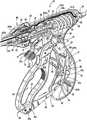
- FIG. 1Ais a left, perspective view of an endoscopic bipolar forceps showing a housing, a shaft and an end effector assembly according to the present disclosure
- FIG. 1Bis a left, perspective of an open bipolar forceps according to the present disclosure
- FIG. 2is a top view of the forceps of FIG. 1 ;
- FIG. 3is a right, side view of the forceps of FIG. 1 ;
- FIG. 4is a right, perspective view of the forceps of FIG. 1 showing the rotation of the end effector assembly about a longitudinal axis “A”;
- FIG. 5is a front view of the forceps of FIG. 1 ;
- FIGS. 6is an enlarged view of the indicated area of detail of FIG. 5 showing an enhanced view of the end effector assembly detailing a pair of opposing jaw members;
- FIG. 7is an enlarged, left perspective view of the indicated area of detail of FIG. 1 showing another enhanced view of the end effector assembly;
- FIG. 8is an enlarged, right side view of the indicated area of detail of FIG. 3 with a pair of cam slots of the end effector assembly shown in phantom;
- FIG. 9is a slightly-enlarged, cross-section of the forceps of FIG. 3 showing the internal working components of the housing;
- FIG. 10is an enlarged, cross-section of the indicated area of detail of FIG. 9 showing the initial position of a knife assembly disposed within the end effector assembly;
- FIG. 11is an enlarged, left perspective view showing the housing without a cover plate and the internal working components of the forceps disposed therein;
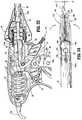
- FIG. 12is an exploded, perspective view of the end effector assembly, the knife assembly and the shaft;
- FIG. 13is an exploded, perspective view of the housing and the internal working components thereof with the attachment of the shaft and end effector assembly to the housing shown in broken line illustration;
- FIG. 14is greatly-enlarged, top perspective view of the end effector assembly with parts separated showing a feed path for an electrical cable through the top jaw member;
- FIG. 15is a longitudinal, cross-section of the indicated area of detail of FIG. 9 ;
- FIG. 16is an enlarged, top perspective view of the end effector assembly showing the feed path for the electrical cable through the opposing jaw members and the proximal attachment of the knife assembly to a longitudinally-reciprocating knife tube disposed within the shaft;
- FIG. 17is an enlarged, top perspective view of the end effector assembly showing the feed path for the electrical cable along a longitudinally-disposed channel defined within the outer periphery of the shaft;
- FIG. 18Ais a greatly-enlarged, side perspective view of the housing without the cover plate showing the feed path for the electrical cable through a rotating assembly adjacent to a distal end of the housing;
- FIG. 18Bis a greatly-enlarged, side perspective view of the housing without the cover plate showing the feed path for the electrical cable through a rotating assembly with the shaft mounted within the housing;
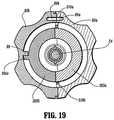
- FIG. 19is a greatly-enlarged, rear view of the rotating assembly showing an internally-disposed stop member
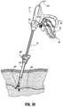
- FIG. 20is a perspective view of the forceps of the present disclosure shown in position to grasp and seal a tubular vessel or bundle through a cannula;
- FIG. 21is a slightly-enlarged, cross-section of the internal, cooperative movements of a four-bar handle assembly disposed within the housing which effects movement of the jaw members relative to one another;
- FIG. 22is a greatly-enlarged, cross-section showing the initial movement of a flange upon activation of the four-bar handle assembly shown in phantom illustration;
- FIG. 23is a greatly-enlarged, side view showing the resulting compression movement of a coil spring in reaction to the movement of the four-bar handle assembly;
- FIG. 24is a greatly-enlarged, side view showing the proximal movement of a cam-like drive pin of the end effector assembly as a result of the proximal compression of the coil spring of FIG. 23 which, in turn, moves the opposing jaw members into a closed configuration;
- FIG. 25is a greatly-enlarged, cross-section showing the knife assembly poised for activation within a cannula
- FIG. 26is a top perspective view showing the opposing jaw members in closed configuration with a tubular vessel compressed therebetween;
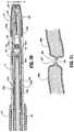
- FIG. 27is an enlarged perspective view of a sealed site of a tubular vessel showing a preferred cutting line “B-B” for dividing the tubular vessel after sealing;
- FIG. 28is a longitudinal cross-section of the sealed site taken along line 28 - 28 of FIG. 27 ;
- FIG. 29is a side view of the housing without a cover plate showing the longitudinal reciprocation of the knife tube upon activation of a trigger assembly
- FIG. 30is a greatly-enlarged, cross-section of the distal end of the instrument showing longitudinal reciprocation of the knife assembly upon activation of the trigger assembly;
- FIG. 31is a longitudinal cross-section of the tubular vessel after reciprocation of the knife assembly through the sealing site along preferred cutting line “B-B” of FIG. 28 ;
- FIG. 32is a greatly-enlarged, side view showing movement of the flange upon re-initiation of the handle assembly along a predefined exit path which, in turn, opens the opposing jaw members and releases the tubular vessel;
- FIG. 33is a greatly enlarged, perspective view showing one particular stop member configuration on one of the vessel sealing surfaces of one of the jaw members;
- FIG. 34Ais an internal side view of the housing showing one embodiment of a handswitch for use with the present disclosure
- FIG. 34Bis a schematic illustration of an alternate embodiment of the handswitch according to the present disclosure.
- FIG. 34Cis a schematic illustration of another embodiment of the handswitch according to the present disclosure.
- FIGS. 35A and 35Bare schematic illustrations of heating blocks according to the present disclosure.
- FIGS. 35C and 35Dare schematic illustrations jaw members with intermittent sealing surface patterns
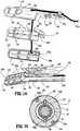
- FIG. 36shows one embodiment of a slide tube cutter in accordance with the present invention
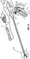
- FIG. 37Ashows one embodiment of a laparoscopic forceps with the slide tube cutter of FIG. 36 wherein the slide tube cutter is poised for longitudinal reciprocation of U-shaped notched blade through a vessel along a seal plane “B-B”;
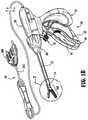
- FIG. 37Bshows another embodiment of a laparoscopic forceps with the slide tube cutter of FIG. 36 wherein the slide tube cutter is poised for longitudinal reciprocation and rotation of U-shaped notched blade through a vessel along a seal plane “B-B”;
- FIGS. 38A and 38Bshow tow alternate embodiments of the slide tube cutter in accordance with the present disclosure
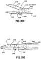
- FIG. 39Ashows a laparoscopic forceps having a unilateral closure mechanism shown in open configuration
- FIG. 39Bshows a laparoscopic forceps having a unilateral closure mechanism shown in closed configuration
- FIG. 39Cshows a laparoscopic forceps having a unilateral closure mechanism shown in open configuration with a knife blade and corresponding knife channel shown in phantom;
- FIG. 39Dshows a laparoscopic forceps having a unilateral closure mechanism shown in closed configuration with a knife blade and corresponding knife channel shown in phantom;
- FIG. 40is an enlarged, cross-section of the end effector assembly showing a hot wire poised for selective reciprocation to cut tissue.
- a bipolar forceps 10for use with various surgical procedures and generally includes a housing 20 , a handle assembly 30 , a rotating assembly 80 , a trigger assembly 70 and an end effector assembly 100 which mutually cooperate to grasp, seal and divide tubular vessels and vascular tissue 420 ( FIG. 20 ).
- an open forceps 10 ′is also contemplated for use in connection with traditional open surgical procedures and is shown by way of example in FIG. 1A .
- the endoscopic versionis discussed in detail, however, it is contemplated that open forceps 10 ′ also includes the same or similar operating components and features as described below.
- forceps 10includes a shaft 12 which has a distal end 14 dimensioned to mechanically engage the end effector assembly 100 and a proximal end 16 which mechanically engages the housing 20 .
- shaft 12is bifurcated at the distal end 14 thereof to form ends 14 a and 14 b which are dimensioned to receive the end effector assembly 100 as best seen in FIGS. 7 and 12 .
- the proximal end 16 of shaft 12includes notches 17 a (See FIGS. 23 and 29 ) and 17 b (See FIGS. 11, 12 and 13 ) which are dimensioned to mechanically engage corresponding detents 83 a ( FIG. 18A ) and 83 b ( FIG.
- proximalas is traditional, will refer to the end of the forceps 10 which is closer to the user, while the term “distal” will refer to the end which is further from the user.
- forceps 10also includes an electrical interface or plug 300 which connects the forceps 10 to a source of electrosurgical energy, e.g., a generator (not shown).
- Plug 300includes a pair of prong members 302 a and 302 b which are dimensioned to mechanically and electrically connect the forceps 10 to the source of electrosurgical energy.
- An electrical cable 310extends from the plug 300 to a sleeve 99 which securely connects the cable 310 to the forceps 10 .
- cable 310is internally divided into cable lead 310 a and 310 b which each transmit electrosurgical energy through their respective feed paths through the forceps 10 to the end effector assembly 100 as explained in more detail below.
- Handle assembly 30includes a fixed handle 50 and a movable handle 40 .
- Fixed handle 50is integrally associated with housing 20 and handle 40 is movable relative to fixed handle 50 as explained in more detail below with respect to the operation of the forceps 10 .
- Rotating assembly 80is preferably attached to a distal end 303 ( FIG. 18A ) of housing 20 and is rotatable approximately 180 degrees in either direction about a longitudinal axis “A”.
- housing 20is formed from two (2) housing halves 20 a and 20 b which each include a plurality of interfaces 307 a, 307 b and 307 c ( FIG. 13 ) which are dimensioned to mechanically align and engage one another to form housing 20 and enclose the internal working components of forceps 10 .
- fixed handle 50which, as mentioned above is integrally associated with housing 20 , takes shape upon the assembly of the housing halves 20 a and 20 b.
- housing halves 20 a and 20 bmay be assembled together in any fashion known in the art.
- alignment pins, snap-like interfaces, tongue and groove interfaces, locking tabs, adhesive ports, etc.may all be utilized either alone or in combination for assembly purposes.
- rotating assembly 80includes two halves 80 a and 80 b which, when assembled, enclose and engage the proximal end 16 of shaft 12 to permit selective rotation of the end effector assembly 100 as needed.
- Half 80 aincludes a pair of detents 89 a ( FIG. 13 ) which are dimensioned to engage a pair of corresponding sockets 89 b (shown in phantom in FIG. 13 ) disposed within half 80 b.
- Movable handle 40 and trigger assembly 70are preferably of unitary construction and are operatively connected to the housing 20 and the fixed handle 50 during the assembly process.
- end effector assembly 100is attached to the distal end 14 of shaft 12 and includes a pair of opposing jaw members 110 and 120 .
- Movable handle 40 of handle assembly 30is ultimately connected to a drive rod 32 which, together, mechanically cooperate to impart movement of the jaw members 110 and 120 from an open position wherein the jaw members 110 and 120 are disposed in spaced relation relative to one another, to a clamping or closed position wherein the jaw members 110 and 120 cooperate to grasp tissue 420 ( FIG. 20 ) therebetween. This is explained in more detail below with respect to FIGS. 9-11 and 20-29 .
- the forceps 10may be designed such that it is fully or partially disposable depending upon a particular purpose or to achieve a particular result.
- end effector assembly 100may be selectively and releasably engageable with the distal end 14 of the shaft 12 and/or the proximal end 16 of shaft 12 may be selectively and releasably engageable with the housing 20 and the handle assembly 30 .
- the forceps 10would be considered “partially disposable” or “reposable”, i.e., a new or different end effector assembly 100 (or end effector assembly 100 and shaft 12 ) selectively replaces the old end effector assembly 100 as needed.
- movable handle 40includes an aperture 42 defined therethrough which enables a user to grasp and move the handle 40 relative to the fixed handle 50 .
- Handle 40also includes an ergonomically-enhanced gripping element 45 disposed along the inner peripheral edge of aperture 42 which is designed to facilitate gripping of the movable handle 40 during activation.
- gripping element 45may include one or more protuberances, scallops and/or ribs 43 a, 43 b and 43 c , respectively, to facilitate gripping of handle 40 .
- movable handle 40is selectively moveable about a pivot 69 from a first position relative to fixed handle 50 to a second position in closer proximity to the fixed handle 50 which, as explained below, imparts movement of the jaw members 110 and 120 relative to one another.
- housing 20encloses a drive assembly 21 which cooperates with the movable handle 40 to impart movement of the jaw members 110 and 120 from an open position wherein the jaw members 110 and 120 are disposed in spaced relation relative to one another, to a clamping or closed position wherein the jaw members 110 and 120 cooperate to grasp tissue therebetween.
- the handle assembly 30can generally be characterized as a four-bar mechanical linkage composed of the following elements: movable handle 40 , a link 65 , a cam-like link 36 and a base link embodied by fixed handle 50 and a pair of pivot points 37 and 67 b.
- Movement of the handle 40activates the four-bar linkage which, in turn, actuates the drive assembly 21 for imparting movement of the opposing jaw members 110 and 120 relative to one another to grasp tissue therebetween. It is envisioned that employing a four-bar mechanical linkage will enable the user to gain a significant mechanical advantage when compressing the jaw members 110 and 120 against the tissue 420 as explained in further detail below with respect the operating parameters of the drive assembly 21 . Although shown as a four-bar mechanical linkage, the present disclosure contemplates other linkages to effect relative motion of the jaw members 110 and 120 as is known in the art.
- fixed handle 50includes a channel 54 defined therein which is dimensioned to receive a flange 92 which extends proximally from movable handle 40 .
- flange 92includes a fixed end 90 which is affixed to movable handle 40 and a t-shaped free end 93 which is dimensioned for facile reception within channel 54 of handle 50 . It is envisioned that flange 92 may be dimensioned to allow a user to selectively, progressively and/or incrementally move jaw members 110 and 120 relative to one another from the open to closed positions.
- flange 92may include a ratchet-like interface which lockingly engages the movable handle 40 and, therefore, jaw members 110 and 120 at selective, incremental positions relative to one another depending upon a particular purpose.
- Other mechanismsmay also be employed to control and/or limit the movement of handle 40 relative to handle 50 (and jaw members 110 and 120 ) such as, e.g., hydraulic, semi-hydraulic, linear actuator(s), gas-assisted mechanisms and/or gearing systems.
- housing halves 20 a and 20 b of housing 20when assembled, form an internal cavity 52 which predefines the channel 54 within fixed handle 50 such that an entrance pathway 53 and an exit pathway 58 are formed for reciprocation of the t-shaped flange end 93 therein.
- two generally triangular-shaped members 57 a and 57 bare positioned in close abutment relative to one another to define a rail or track 59 therebetween.
- the t-shaped end 93rides along track 59 between the two triangular members 57 a and 57 b according to the particular dimensions of the triangularly-shaped members 57 a and 57 b, which, as can be appreciated, predetermines part of the overall pivoting motion of handle 40 relative to fixed handle 50 .
- handle 40moves in a generally arcuate fashion towards fixed handle 50 about pivot 69 which causes link 65 to rotate proximally about pivots 67 a and 67 b which, in turn, cause cam-like link 36 to rotate about pivots 37 and 69 in a generally proximal direction. Movement of the cam-like link 36 imparts movement to the drive assembly 21 as explained in more detail below. Moreover, proximal rotation of the link 65 about pivots 67 a and 67 b also causes a distal end 63 of link 65 to release, i.e., “unlock”, the trigger assembly 70 for selective actuation. This feature is explained in detail with reference to FIGS. 21-29 and the operation of the knife assembly 200 .
- FIG. 12shows an exploded view of the shaft 12 and end effector assembly 100 .
- shaft 12includes distal and proximal ends 14 and 16 , respectively.
- the distal end 14is bifurcated and includes ends 14 a and 14 b which, together, define a cavity 18 for receiving the end effector assembly 100 .
- the proximal end 16includes a pair of notches 17 a ( FIG. 29 ) and 17 b ( FIG. 11 ) which are dimensioned to engage corresponding detents 83 a and 83 b ( FIG. 13 ) of the rotating assembly 80 .
- actuation of the rotation assembly 80rotates the shaft 12 which, in turn, rotates the end effector assembly 100 to manipulate and grasp tissue 420 .
- Shaft 12also includes a pair of longitudinally-oriented channels 19 a ( FIG. 15 ) and 19 b ( FIG. 12 ) which are each dimensioned to carry an electrosurgical cable lead 310 a and 310 b, respectively, therein for ultimate connection to each jaw member 120 and 110 , respectively, as explained in more detail with reference to FIGS. 14-17 below.
- Shaft 12also includes a pair of longitudinally oriented slots 197 a and 197 b disposed on ends 14 a and 14 b, respectively. Slots 197 a and 197 b are preferable dimensioned to allow longitudinal reciprocation of a cam pin 170 therein which, as explained below with reference to FIGS. 23 and 24 , causes movement of the opposing jaw member 110 and 120 from the open to closed positions.
- Shaft 12also includes a pair of sockets 169 a and 169 b disposed at distal ends 14 a and 14 b which are dimensioned to receive a corresponding pivot pin 160 .
- pivot pin 160secures jaws 110 and 120 to the shaft 12 between bifurcated distal ends 14 a and 14 b and mounts the jaw members 110 and 120 such that longitudinal reciprocation of the cam pin 170 rotates jaw members 110 and 120 about pivot pin 160 from the open to closed positions.
- Knife tube 34includes a rim 35 located at a proximal end thereof and a pair of opposing notches 230 a and 230 b ( FIGS. 25 and 30 ) located at a distal end 229 thereof. As best shown in FIG.
- rim 35is dimensioned to engage a corresponding sleeve 78 disposed at a distal end of the trigger assembly 70 such that distal movement of the sleeve 78 translates the knife tube 34 which, in turn, actuates the knife assembly 200 .
- a seal 193may be mounted atop the knife tube 34 and positioned between the knife tube 34 and the shaft 12 . It is envisioned that the seal 193 may be dimensioned to facilitate reciprocation of the knife tube 34 within the shaft 12 and/or to protect the other, more sensitive, internal operating components of the forceps from undesirable fluid inundation during surgery. Seal 193 may also be employed to control/regulate pneumo-peritoneal pressure leakage through forceps 10 during surgery. Seal 193 preferably includes a pair of opposing bushings 195 a and 195 b which assure consistent and accurate reciprocation of the knife tube 34 within shaft 12 (See FIG. 15 ).
- Notches 230 a and 230 bare preferably dimensioned to engage a corresponding key-like interface 211 of the knife assembly 200 which includes a pair of opposing detents 212 a and 212 b and a pair of opposing steps 214 a and 214 b.
- each detent and step arrangemente.g., 212 a and 214 a , respectively, securely engages a corresponding notch, e.g., 230 a, such that the distal end of the step 214 a abuts the distal end 229 of the knife tube 34 . It is envisioned that engaging the knife tube 34 to the knife assembly 200 in this manner will assure consistent and accurate distal translation of the knife tube 34 through the tissue 420 .
- the knife tube 34 and knife assembly 200are preferably assembled to operate independently from the operation of the drive assembly 21 .
- knife assembly 200is dependent on the drive assembly 21 for activation purposes, i.e., the activation/movement of the drive assembly 21 (via handle assembly 30 and the internal working components thereof) “unlocks” the knife assembly 200 for selective, separation of the tissue.
- the drive assembly 21consists of both the drive rod 32 and the compression mechanism 24 which includes a number of cooperative elements which are described below with reference to FIG. 13 . It is envisioned that arranging the drive assembly 21 in this fashion will enable facile, selective engagement of the drive rod 32 within the compression mechanism 24 for assembly purposes.
- the housing 20may include a release mechanism (not shown) which enables selectively replacement of the drive rod 32 for disposal purposes.
- the forcepswill be considered “partially disposable” or “reposable”, i.e., the shaft 12 , end effector assembly 100 and knife assembly 200 are disposable and/or replaceable whereas the housing 20 and handle assembly 30 are re-usable.
- drive rod 32includes a pair of chamfered or beveled edges 31 a and 31 b at a distal end thereof which are preferably dimensioned to allow facile reciprocation of the drive rod 32 through a knife carrier or guide 220 which forms a part of the knife assembly 200 .
- a pin slot 39is disposed at the distal tip of the drive rod 32 and is dimensioned to house the cam pin 170 such that longitudinal reciprocation of the drive rod 32 within the knife tube 34 translates the cam pin 170 , which, in turn, rotates the jaw members 110 and 120 about pivot pin 160 .
- the cam pin 170rides within slots 172 and 174 of the jaw members 110 and 120 , respectively, which causes the jaw members 110 and 120 to rotate from the open to closed positions about the tissue 420 .
- the proximal end of the drive rod 32includes a tab 33 which is preferably dimensioned to engage a corresponding compression sleeve 28 disposed within the compression mechanism 24 .
- Proximal movement of the sleeve 28(as explained below with respect to FIGS. 21-24 ) reciprocates (i.e., pulls) the drive rod 32 which, in turn, pivots the jaw members 110 and 120 from the open to closed positions.
- Drive rod 32also includes a donut-like spacer or o-ring 95 which is dimensioned to maintain pneumo-peritoneal pressure during endoscopic procedures. It is also envisioned that o-ring 95 may also prevent the inundation of surgical fluids which may prove detrimental to the internal operating components of the forceps 10 .
- O-ring 95is made also be made from a material having a low coefficient of friction to facilitate uniform and accurate reciprocation of the drive rod 32 within the knife tube 34 .
- Knife assembly 200is disposed between opposing jaw members 110 and 120 of the end effector assembly 100 .
- the knife assembly 200 and the end effector assembly 100are independently operable, i.e., the trigger assembly 70 actuates the knife assembly 200 and the handle assembly 30 actuates the end effector assembly 100 .
- Knife assembly 200includes a bifurcated knife bar or rod 210 having two forks 210 a and 210 b and a knife carrier or guide 220 .
- Knife forks 210 a and 210 binclude the above-described key-like interfaces 211 (composed of steps 214 a, 214 b and detents 212 a, 212 b, respectively) disposed at the proximal end thereof for engaging the knife tube 34 (as described above) and a common distal end 206 which carries a blade 205 thereon for severing tissue 420 .
- each fork 210 a and 210 bincludes a taper 213 a and 213 b , respectively, which converge to form common distal end 206 .
- the tapers 213 a and 213 bfacilitate reciprocation of the knife blade 205 through the end effector assembly 100 as described in more detail below and as best illustrated in FIG. 30 .
- Each fork 210 a and 210 balso includes a tapered shoulder portion 221 a and 221 b disposed along the outer periphery thereof which is dimensioned to engage a corresponding slot 223 a and 223 b, respectively, disposed in the knife carrier or guide 220 (See FIG. 16 ). It is envisioned that this shoulder portion 221 a, 221 b and slot 223 a, 223 b arrangement may be designed to restrict and/or regulate the overall distal movement of the blade 205 after activation.
- Each fork 210 a and 210 balso includes an arcuately-shaped notch 215 a and 215 b, respectively disposed along the inward edge thereof which is dimensioned to facilitate insertion of a roller or bushing 216 disposed between the jaw members 110 and 120 during assembly.
- knife assembly 200also includes a knife carrier or guide 220 which includes opposing spring tabs 222 a and 222 b at a proximal end thereof and upper and lower knife guides 224 a and 224 b, respectively, at the distal end thereof.
- the inner facing surface of each spring tab, e.g., 222 b,is preferably dimensioned to matingly engage a corresponding chamfered edge, e.g., 31 b of the drive rod 32 ( FIG. 16 ) and the outer facing surface is preferably dimensioned for friction-fit engagement with the inner periphery of the shaft 12 .
- a knife carrier or guide 220which includes opposing spring tabs 222 a and 222 b at a proximal end thereof and upper and lower knife guides 224 a and 224 b, respectively, at the distal end thereof.
- the inner facing surface of each spring tab, e.g., 222 bis preferably dimensioned to matingly engage a corresponding chamf
- knife carrier 220also includes a drive rod channel 225 defined therethrough which is dimensioned to allow reciprocation of the drive rod 32 during the opening and closing of the jaw members 110 and 120 .
- Knife guide 220also includes rests 226 a and 226 b which extend laterally therefrom which abut the proximal ends 132 , 134 of the jaw members 110 and 120 when disposed in the closed position.
- Knife guides 224 a and 224 bpreferably include slots 223 a and 223 b , respectively, located therein which guide the knife forks 210 a and 210 b therealong during activation to provide consistent and accurate reciprocation of the knife blade 205 through the tissue 420 . It is envisioned that slots 223 a and 223 b also restrict undesirable lateral movements of the knife assembly 200 during activation.
- the knife carrier 220is positioned at a point slightly beyond the shoulder portions 221 a and 221 b when assembled.
- the knife assembly 200also includes a roller or bushing 216 which is dimensioned to mate with the inner peripheral edge of each fork 210 a and 210 b such that, during activation, the forks 210 a and 210 b glide over the roller or bushing 216 to assure facile and accurate reciprocation of the knife assembly 200 through the tissue 420 .
- Bushing 216is also dimensioned to seat between opposing jaw members 110 and 120 and is preferably secured therebetween by pivot pin 160 . As mentioned above, the arcuately-shaped notches 215 a and 215 b facilitate insertion of the bushing 216 during assembly.
- the end effector assembly 100includes opposing jaw members 110 and 120 which are seated within cavity 18 defined between bifurcated ends 14 a and 14 b of shaft 12 .
- Jaw members 110 and 120are generally symmetrical and include similar component features which cooperate to permit facile rotation about pivot pin 160 to effect the sealing and dividing of tissue 420 .
- jaw member 110 and the operative features associated therewithare describe in detail herein but as can be appreciated, many of these features apply to jaw member 120 as well.
- jaw member 110includes a pivot flange 166 which has an arcuately-shaped inner surface 167 which is dimensioned to allow rotation of jaw member 110 about bushing 216 and pivot pin 160 upon reciprocation of drive rod 32 as described above.
- Pivot flange 166also includes a cam slot 172 which is dimensioned to engage cam pin 170 such that longitudinal movement of the drive rod 32 causes the cam pin 170 to ride along cam slot 172 .
- cam slot 172may be dimensioned to allow different rotational paths depending upon a particular purpose or to achieve a particular result.
- commonly assigned, co-pending U.S. application Ser. No. 09/177,950which is hereby incorporated by reference in its entirety herein, describes a two-stage cam slot arrangement which, as can be appreciated, provides a unique rotational path for the jaw members about the pivot point.
- Pivot flange 166also includes a recess 165 which is preferably dimensioned to secure one free end of the bushing 216 between jaw members 110 and 120 .
- the inner periphery of recess 165is preferably dimensioned to receive pivot pin 160 therethrough to secure the jaw member 110 to the shaft 12 .
- Jaw member 120includes a similar recess 175 ( FIG. 14 ) which secures the opposite end of bushing 216 and jaw member 120 to shaft 12 .
- Jaw member 110also includes a jaw housing 116 , an insulative substrate or insulator 114 and an electrically conducive surface 112 .
- Jaw housing 116includes a groove (not shown—See groove 179 of jaw member 120 ) defined therein which is dimensioned to engage a ridge-like interface 161 disposed along the outer periphery of insulator 114 .
- Insulator 114is preferably dimensioned to securely engage the electrically conductive sealing surface 112 . This may be accomplished by stamping, by overmolding, by overmolding a stamped electrically conductive sealing plate and/or by overmolding a metal injection molded seal plate.
- All of these manufacturing techniquesproduce an electrode having an electrically conductive surface 112 which is substantially surrounded by an insulating substrate 114 .
- the insulator 114 , electrically conductive sealing surface 112 and the outer, non-conductive jaw housing 116are preferably dimensioned to limit and/or reduce many of the known undesirable effects related to tissue sealing, e.g., flashover, thermal spread and stray current dissipation.
- the jaw members 110 and 120may be manufactured from a ceramic-like material and the electrically conductive surface(s) 112 are coated onto the ceramic-like jaw members 110 and 120 .
- the electrically conductive sealing surface 112may also include a pinch trim 119 ( FIG. 25 ) which facilitates secure engagement of the electrically conductive surface 112 to the insulating substrate 114 and also simplifies the overall manufacturing process. It is envisioned that the electrically conductive sealing surface 112 may also include an outer peripheral edge which has a radius and the insulator 114 meets the electrically conductive sealing surface 112 along an adjoining edge which is generally tangential to the radius and/or meets along the radius. Preferably, at the interface, the electrically conductive surface 112 is raised relative to the insulator 114 .
- Insulator 114also includes an inwardly facing finger 162 which abuts pivot flange 166 and is designed to restrict/reduce proximal tissue spread and/or isolate the electrically conductive sealing surface 112 from the remaining end effector assembly 100 during activation.
- the electrically conductive surface 112 and the insulator 114when assembled, form a longitudinally-oriented channel 168 a, 168 b defined therethrough for reciprocation of the knife blade 205 . More particularly, and as best illustrated in FIG. 14 , insulator 114 includes a first channel 168 b which aligns with a second channel 168 a on electrically conductive sealing surface 112 to form the complete knife channel.
- the knife channel 168 a, 168 bfacilitates longitudinal reciprocation of the knife blade 205 along a preferred cutting plane “B-B” to effectively and accurately separate the tissue 420 along the formed tissue seal 425 (See FIGS. 27, 28 and 31 .
- jaw member 120include similar elements which include: a pivot flange 176 which has an arcuately-shaped inner surface 177 , a cam slot 174 , and a recess 175 ; a jaw housing 126 which includes a groove 179 which is dimensioned to engage a ridge-like interface 171 disposed along the outer periphery of an insulator 124 ; the insulator 124 which includes an inwardly facing finger 172 which abuts pivot flange 176 ; and an electrically conducive sealing surface 122 which is dimensioned to securely engage the insulator 124 .
- the electrically conductive surface 122 and the insulator 124when assembled, form a longitudinally-oriented channel 178 a, 178 b defined therethrough for reciprocation of the knife blade 205 .
- each jaw membere.g., 110
- each jaw memberincludes a uniquely-designed electrosurgical cable path disposed therethrough which transmits electrosurgical energy to the electrically conductive sealing surfaces 112 , 122 .
- jaw member 110includes a cable guide 181 a disposed atop pivot flange 166 which directs cable lead 310 a towards an aperture 188 disposed through jaw housing 116 .
- Aperture 188directs cable lead 310 a towards electrically conductive sealing surface 112 through a window 182 disposed within insulator 114 .
- a second cable guide 181 bsecures cable lead 310 a along the predefined cable path through window 182 and directs a terminal end 310 a ′ of the cable lead 310 a into crimp-like electrical connector 183 disposed on an opposite side of the electrically conductive sealing surface 112 .
- cable lead 310 ais held loosely but securely along the cable path to permit rotation of the jaw member 110 about pivot 169 .
- Jaw member 120includes a similar cable path disposed therein and therethrough which includes similarly dimensioned cable guides, apertures and electrical connectors which are not shown in the accompanying illustrations.
- FIGS. 15-17also show the presently disclosed feed path for both electrosurgical cable leads 310 a and 310 b along the outer periphery of the shaft 12 and through each jaw member 110 and 120 . More particularly, FIG. 15 shows a cross section of the electrosurgical cable leads 310 a and 310 b disposed within channels 19 a and 19 b , respectively, along shaft 12 . FIGS. 16 and 17 show the feed path of the cable leads 310 a and 310 b from the opposite channels 19 a and 19 b of the shaft 12 through the pivot flanges 166 and 176 of the jaw members 110 and 120 , respectively.
- this unique cable feed path for cable leads 310 a and 310 b from the shaft 12 to the jaw members 110 and 120not only electrically isolates each jaw member 100 and 120 but also allows the jaw members 110 and 120 to pivot about pivot pin 160 without unduly straining or possibly tangling the cable leads 310 a and 310 b.
- the crimp-like electrical connector 183(and the corresponding connector in jaw member 120 ) greatly facilitates the manufacturing and assembly process and assures a consistent and tight electrical connection for the transfer of energy through the tissue 420 . As best shown in FIG.
- the outer surface of shaft 12may be covered by heat shrink tubing 500 or the like which protects the cable leads 310 a and 310 b from undue wear and tear and secures cable leads 310 a and 310 b within their respective channels 19 a and 19 b.
- FIGS. 18A and 18Bshow the feed path of the cable leads 310 a and 310 b through the rotating assembly 80 which, again, allows the user added flexibility during the use of the forceps 10 due to the uniqueness of the feed path. More particularly, FIG. 18A shows the feed path of cable lead 310 a through half 80 a of the rotating assembly 80 and FIG. 18B shows the path of cable leads 310 a and 310 b as the cable leads 310 a and 310 b feed through the instrument housing 20 a, through half 80 a of the rotating assembly 80 and to the channels 19 a and 19 b of the shaft 12 .
- FIG. 18Ashows the feed path of cable lead 310 a through half 80 a of the rotating assembly 80
- FIG. 18Bshows the path of cable leads 310 a and 310 b as the cable leads 310 a and 310 b feed through the instrument housing 20 a, through half 80 a of the rotating assembly 80 and to the channels 19 a and 19 b of the shaft 12 .
- each cable leade.g., 310 a
- each cable leadis looped through each half 80 a of the rotating assembly 80 to form slack-loops 321 a and 321 b which traverse either side of longitudinal axis “A”.
- Slack-loop 321 aredirects cable lead 310 a across one side of axis “A” and slack-loop 321 b returns cable lead 310 a across axis “A”. It is envisioned that feeding the cable leads 310 a and 310 b through the rotating assembly 80 in this fashion allows the user to rotate the shaft 12 and the end effector assembly 100 without unduly straining or tangling the cable leads 310 a and 310 b which may prove detrimental to effective sealing. Preferably, this loop-like cable feed path allows the user to rotate the end effector assembly 100 about 180 degrees in either direction without straining the cable leads 310 a and 310 b. The presently disclosed cable lead feed path is envisioned to rotate the cable leads 310 a and 310 b approximately 178 degrees in either direction.
- FIG. 19shows an internal view of half 80 a of the rotating assembly 80 as viewed along axis “A” to highlight the internal features thereof. More particularly, at least one stop 88 is preferably positioned within each rotating half 80 a and 80 b which operates to control the overall rotational movement of the rotating assembly 80 to about 180 degree in either direction.
- the stop member 88is dimensioned to interface with a corresponding notch 309 c disposed along the periphery of outer flange 309 to prevent unintended over-rotation of the rotating assembly 80 which may unduly strain one or both of the cable leads 310 a and 310 b.
- FIG. 18Bshows the feed path of the electrical cable leads 310 a and 310 b from the housing 20 a, through the rotating assembly 80 and to the shaft 12 .
- the cable leads 310 a and 310 bare directed through each part of the forceps 10 via a series of cable guide members 311 a - 311 g disposed at various positions through the housing 20 and rotating assembly 80 .
- a series of mechanical interfacese.g., 309 a, 309 b ( FIG. 13 ) and 323 a , 323 b ( FIG. 13 ) may also be dimensioned to contribute in guiding cables 310 a and 310 b through the housing 20 and rotating assembly 80 .
- FIG. 13shows the exploded view of the housing 20 , rotating assembly 80 , trigger assembly 70 and handle assembly 30 , it is envisioned that all of these various component parts along with the shaft 12 and the end effector assembly 100 are assembled during the manufacturing process to form a partially and/or fully disposable forceps 10 .
- the shaft 12 and/or end effector assembly 100may be disposable and, therefore, selectively/releasably engagable with the housing 20 and rotating assembly 80 to form a partially disposable forceps 10 and/or the entire forceps 10 may be disposable after use.
- Housing 20is preferably formed from two housing halves 20 a and 20 b which engage one another via a series of mechanical interfaces 307 a, 307 b, 307 c and 308 a , 308 b, 308 c respectively, to form an internal cavity 300 for housing the hereindescribed internal working components of the forceps 10 .
- housing halves 20 a and 20are generally symmetrical and, unless otherwise noted, a component described with respect to housing half 20 a will have a similar component which forms a part of housing half 20 b.
- Housing half 20 aincludes proximal and distal ends 301 a and 303 a , respectively.
- Proximal end 301 ais preferably dimensioned to receive an electrical sleeve 99 which secures the electrosurgical cable 310 ( FIG. 1 ) within the housing 20 .
- paired cable 310splits into two electrosurgical cable leads 310 a and 310 b which are subsequently fed through the housing 20 to ultimately transmit different electrical potentials to the opposing jaw members 110 and 120 .
- various cable guides 311 a - 311 gare positioned throughout the housing 20 and the rotating assembly 80 to direct the cable leads 310 a and 310 b to the channels 19 a and 19 b disposed along the outer periphery of the shaft 12 .
- the distal end 303 ais generally arcuate in shape such that, when assembled, distal ends 303 a and 303 b form a collar 303 ( FIG. 13 ) which extends distally from the housing 20 .
- Each distal end 303 a, 303 b of the collar 303includes an outer flange 309 a , 309 b and a recess 323 a, 323 b which cooperate to engage corresponding mechanical shoulders 84 a, 84 b ( FIG. 29 ) and flanges 87 a, 87 b, respectively, disposed within the rotating assembly 80 .
- the interlocking engagement of the flanges 309 a, 309 b with the shoulders 84 a, 84 b and the recesses 323 a, 323 b with the flanges 87 a, 87 bare dimensioned to allow free rotation about of the rotating assembly 80 about collar 303 when assembled.
- the stop member(s) 88 and the notch(es)mechanically cooperate to limit rotational movement of the rotating assembly 80 to avoid straining cable leads 310 a and 310 b.
- Each distal end 303 a, 303 b of collar 303also includes an inner cavity 317 a and 317 b ( FIGS. 9 and 21 ), respectively, defined therein which is dimensioned to permit free rotation of the shaft 12 , knife tube 34 and cable leads 310 a and 310 b housed therein.
- a plurality of detents 89 a located within rotating assembly 80engage a corresponding plurality of sockets 89 b ( FIG. 13 ) disposed within rotating half 80 b to poise the rotating assembly 80 in rotational relationship atop collar 303 .
- Housing half 20 aalso includes a plurality of hub-like pivot mounts 329 a , 331 a and 333 a which as explained in more detail below with respect to the operation of the instrument, cooperate with opposite hub-like pivot mounts (shown in phantom in FIG. 13 ) disposed on housing half 20 b to engage the free ends of pivot pins 37 , 67 b and 77 , respectively, which are associated with the different operating components described below.
- each of these mounts 329 a, 331 a and 333 aprovide a fixed point of rotation for each pivoting element, namely, cam link 36 , handle link 65 and trigger assembly 70 , respectively.
- fixed handle 50which takes shape upon the assembly of housing 20 includes a scallop-like outer surface 51 and an internal cavity 52 defined therein. As mentioned above with respect to the discussion of FIG. 11 , these elements and the other internal elements of the fixed handle 50 cooperate with movable handle 40 to activates the four-bar mechanical linkage which, in turn, actuates the drive assembly 21 for imparting movement of the opposing jaw members 110 and 120 relative to one another to grasp tissue 420 therebetween.
- the handle assembly 30which includes the above-mentioned fixed handle 50 and movable handle 40 also includes the cam link 36 which is generally triangular in shape.
- the cam linkincludes an upper piston 38 , a fixed pivot 37 and a handle pivot 69 .
- Cam linkis assembled within the internal cavity 300 of housing 20 between housing halves 20 a and 20 b. More particularly, fixed pivot 37 is rotatingly mounted within fixed mounts 329 a and 329 b between opposing housing halves 20 a and 20 b and the handle pivot 69 is rotatingly mounted within the bifurcated end of handle 40 through apertures 68 a and 68 b .
- Link 65is also associated with the handle assembly 30 and forms an integral part of the four-bar mechanical linkage.
- Link 65includes a distal end 63 and two pivot pins 67 a and 67 b.
- Pivot pin 67 aengages apertures 68 a and 68 b disposed within the movable handle 40 and pivot 67 b engages fixed mounts 331 a and 331 b between housing halves 20 a and 20 b such that movement of the handle 40 towards fixed handle 50 pivots link 65 about pivots 67 a and 67 b.
- distal end 63acts as a lockout for the trigger assembly 70 .
- Movable handle 40includes a flange 92 which is preferably mounted to the movable handle 40 by pins 46 a and 46 b which engage apertures 41 a and 41 b disposed within handle 40 and apertures 91 a and 91 b disposed within flange 92 , respectively. Other methods of engagement are also contemplated, snap-lock, spring tab, etc.
- Flange 92also includes a t-shaped distal end 93 which, as mentioned above with respect to FIG. 11 , rides within a predefined channel 54 disposed within fixed handle 50 . Additional features with respect to the t-shaped end 93 are explained below in the detailed discussion of the operational features of the forceps 10 .
- a drive assembly 21is preferably positioned within the housing 20 between housing halves 20 a and 20 b.
- the drive assembly 21includes the previously described drive rod 32 and the compression mechanism 24 .
- Compression mechanism 24includes a compression sleeve 27 which is telescopically and/or slidingly disposed within a spring mount 26 .
- the distal end 28 of the compression sleeve 27is preferably C-shaped and dimensioned to engage the tab 33 disposed at the proximal end of drive rod 32 such that longitudinal movement of the compression sleeve 27 actuates the drive rod 32 .
- the proximal end of the compression sleeve 27is dimensioned to engage a barbell-shaped compression tab 25 which is disposed within a longitudinal slot 25 s of the spring mount 26 .
- the compression sleeve 27also includes a longitudinal slot or channel 25 c which is longitudinally aligned with slot 25 s and is dimensioned to receive the cam piston 38 of the cam link 36 described above.
- the proximal end of spring mount 26includes a circular flange 23 which is dimensioned to bias the compression spring 22 once the compression mechanism 24 is assembled and seated within housing 20 ( FIG. 11 ).
- the distal end of spring mount 26includes a flange 25 f which restricts distal movement of the tab 25 to within the slot 25 s of the spring mount 26 and biases the opposite end the spring 22 .
- spring 22is poised for compression atop spring mount 26 upon actuation of the handle assembly 30 . More particularly, movement of the cam piston 38 within slot 25 c (via movement of handle assembly 30 ) moves the tab 25 atop slot 25 s and reciprocates the compression sleeve 27 within the spring mount 26 to compress the spring 22 . Proximal movement of the compression sleeve 27 imparts proximal movement to the drive rod 32 which closes jaw members 110 and 120 about tissue 420 ( FIG. 26 ). Compression of the spring 22 may be viewed through one or more windows 340 disposed within the housing halves, e.g., 20 b.
- FIG. 13also shows the trigger assembly 70 which activates the knife assembly 200 as described above with respect to FIG. 12 .
- trigger assembly 70includes an actuator 73 having a cuff-like distal end 78 which is dimensioned to receive the proximal rim 35 of the knife tube 34 .
- a drive pin 74extends laterally from the proximal end of actuator 73 .
- Trigger assembly 70also includes an ergonomically enhanced finger tab 72 having opposing wing-like flanges 72 a and 72 b which are envisioned to facilitate gripping and firing of the trigger assembly during surgery.
- the compression sleeve 27is dimensioned to slide internally within actuator 73 when the forceps 10 is assembled.
- the actuator 73when activated, can slide distally along the outer periphery of compression sleeve 27 to actuate the knife assembly 200 as described above with respect to FIG. 12 .
- the drive pin 74is dimensioned to ride along a pair of guide rails 71 a and 71 b disposed within a bifurcated tail portion of finger tab 72 which includes ends 76 a and 76 b , respectively.
- a hinge or pivot pin 77mounts the finger tab 72 between housing halves 20 a and 20 within mounts 333 a and 333 b.
- a torsion spring 75may also be incorporated within the trigger assembly 70 to facilitate progressive and consistent longitudinal reciprocation of the actuator 73 and knife tube 34 to assure reliable separation along the tissue seal 425 ( FIGS. 27 and 28 ).
- the trigger assembly 70is configured in a proximal, “pre-loaded” configuration prior to activation. This assures accurate and intentional reciprocation of the knife assembly 200 .
- the “pre-load” configuration of the torsion spring 75acts as an automatic recoil of the knife assembly 200 to permit repeated reciprocation through the tissue as needed.
- a plurality of gripping elements 71is preferably incorporated atop the finger tab 72 and wing flanges 72 a and 72 b to enhance gripping of the finger tab 72 .
- the trigger assembly 70is initially prevented from firing due to the unique configuration of the distal end 63 of the link 65 which abuts against the finger tab 72 and “locks” the trigger assembly 70 prior to actuation of the handle assembly 30 .
- the opposing jaw members 110 and 120may be rotated and partially opened and closed without unlocking the trigger assembly 70 which, as can be appreciated, allows the user to grip and manipulate the tissue 420 without premature activation of the knife assembly 200 .
- FIGS. 21-29The operating features and relative movements of the internal working components of the forceps 10 are shown by phantom representation and directional arrows and are best illustrated in FIGS. 21-29 .
- a predefined channel 54is formed within the cavity 52 of fixed handle 50 .
- the channel 54includes entrance pathway 53 and an exit pathway 58 for reciprocation of the flange 92 and the t-shaped end 93 therein.
- the two generally triangular-shaped members 57 a and 57 bare positioned in close abutment relative to one another and define track 59 disposed therebetween.
- FIGS. 21 and 22show the initial actuation of handle 40 towards fixed handle 50 which causes the free end 93 of flange 92 to move generally proximally and upwardly along entrance pathway 53 .
- the t-shaped end 93rides along track 59 between the two triangular members 57 a and 57 b.
- the utilization of a four-bar linkagewill enable the user to selectively compress the coil spring 22 a specific distance which, in turn, imparts a specific load on the drive rod 32 .
- the drive rod 32 loadis converted to a torque about the jaw pivot 160 by way of cam pin 170 .
- a specific closure forcecan be transmitted to the opposing jaw members 110 and 120 .
- window 340 disposed in the housing 20may include graduations, visual markings or other indicia which provide feedback to the user during compression of the handle assembly 30 .
- the usercan thus selectively regulate the progressive closure forces applied to the tissue 420 to accomplish a particular purpose or achieve a particular result.
- the window 340may include a specific visual indicator which relates to the proximal-most position of flange 93 prior to engagement within the catch basin 62 .
- the jaw members 110 and 120may be opened, closed and rotated to manipulate tissue 420 until sealing is desired without unlocking the trigger assembly 70 .
- Thisenables the user to position and re-position the forceps 10 prior to activation and sealing. More particularly, as illustrated in FIG. 4 , the end effector assembly 100 is rotatable about longitudinal axis “A” through rotation of the rotating assembly 80 .
- the unique feed path of the cable leads 310 a and 310 b through the rotating assembly 80 , along shaft 12 and, ultimately, through the jaw members 110 and 120enable the user to rotate the end effector assembly 100 about 180 degrees in both the clockwise and counterclockwise direction without tangling or causing undue strain on the cable leads 310 a and 310 b. As can be appreciated, this facilitates the grasping and manipulation of tissue 420 .
- a series of stop members 150 a - 150 fare preferably employed on the inner facing surfaces of the electrically conductive sealing surfaces 112 and 122 to facilitate gripping and manipulation of tissue and to define a gap “G” ( FIG. 24 ) between opposing jaw members 110 and 120 during sealing and cutting of tissue.
- a detailed discussion of these and other envisioned stop members 150 a - 150 f as well as various manufacturing and assembling processes for attaching and/or affixing the stop members 150 a - 150 f to the electrically conductive sealing surfaces 112 , 122are described in commonly-assigned, co-pending U.S. Application Ser. No. PCT/US01/11413 entitled “VESSEL SEALER AND DIVIDER WITH NON-CONDUCTIVE STOP MEMBERS” by Dycus et al. which is hereby incorporated by reference in its entirety herein.
- handle 40may be compressed fully such that the t-shaped end 93 of flange 92 clears a predefined rail edge 61 located atop the triangular-shaped members 57 a and 57 b. Once end 93 clears edge 61 , distal movement of the handle 40 and flange 92 , i.e., release, is redirected by edge 61 into a catch basin 62 located within the exit pathway 58 . More particularly, upon a slight reduction in the closing pressure of handle 40 against handle 50 , the handle 40 returns slightly distally towards entrance pathway 53 but is re-directed towards exit pathway 58 .
- end effector assembly 100 and/or the jaw members 110 and 120may be dimensioned to off-load some of the excessive clamping forces to prevent mechanical failure of certain internal operating elements of the end effector 100 .
- the combination of the four-bar mechanical advantage along with the compressive force associated with the compression spring 22facilitate and assure consistent, uniform and accurate closure pressure about the tissue 420 .
- the usercan either cauterize, coagulate/desiccate, seal and/or simply reduce or slow bleeding.
- two mechanical factorsplay an important role in determining the resulting thickness of the sealed tissue and effectiveness of the seal 425 , i.e., the pressure applied between opposing jaw members 110 and 120 and the gap distance “G” between the opposing sealing surfaces 112 , 122 of the jaw members 110 and 120 during the sealing process.
- thickness of the resulting tissue seal 425cannot be adequately controlled by force alone. In other words, too much force and the two jaw members 110 and 120 would touch and possibly short resulting in little energy traveling through the tissue 420 thus resulting in a bad tissue seal 425 . Too little force and the seal 425 would be too thick.
- Applying the correct forceis also important for other reasons: to oppose the walls of the vessel; to reduce the tissue impedance to a low enough value that allows enough current through the tissue 420 ; and to overcome the forces of expansion during tissue heating in addition to contributing towards creating the required end tissue thickness which is an indication of a good seal 425 .
- the electrically conductive sealing surfaces 112 , 122 of the jaw members 110 , 120are relatively flat to avoid current concentrations at sharp edges and to avoid arcing between high points.
- jaw members 110 and 120are preferably manufactured to resist bending.
- the jaw members 110 and 120may be tapered along the width thereof which is advantageous for two reasons: 1) the taper will apply constant pressure for a constant tissue thickness at parallel; 2) the thicker proximal portion of the jaw members 110 and 120 will resist bending due to the reaction force of the tissue 420 .
- the jaw members 110 and 120may be curved in order to reach specific anatomical structures.
- dimensioning the jaw members 110 and 120 at an angle of about 50 degrees to about 70 degreesis preferred for accessing and sealing specific anatomical structures relevant to prostatectomies and cystectomies, e.g., the dorsal vein complex and the lateral pedicles.
- the knife assembly 200(or one or more of the components thereof) may be made from a semi-compliant material or may be multi-segmented to assure consistent, facile and accurate cutting through the above envisioned curved jaw member 110 and 120 .
- At least one jaw member, e.g., 110may include a stop member, e.g., 150 a, which limits the movement of the two opposing jaw members 110 and 120 relative to one another ( FIGS. 6 and 7 ).
- the stop member, e.g., 150 aextends from the sealing surface 112 , 122 a predetermined distance according to the specific material properties (e.g., compressive strength, thermal expansion, etc.) to yield a consistent and accurate gap distance “G” during sealing ( FIG. 24 ).
- the gap distance between opposing sealing surfaces 112 and 122 during sealingranges from about 0.001 inches to about 0.005 inches and, more preferably, between about 0.002 and about 0.003 inches.
- stop members 150 a - 150 fare made from an insulative material, e.g., parylene, nylon and/or ceramic and are dimensioned to limit opposing movement of the jaw members 110 and 120 to within the above mentioned gap range. It is envisioned that the stop members 150 a - 150 f may be disposed one or both of the jaw members 110 and 120 depending upon a particular purpose or to achieve a particular result. Many different configurations for the stop members 150 a - 150 f are discussed in detail in commonly-assigned, co-pending U.S. Application Ser. No. PCT/US01/11413 entitled “VESSEL SEALER AND DIVIDER WITH NON-CONDUCTIVE STOP MEMBERS” by Dycus et al. which is hereby incorporated by reference in its entirety herein.
- FIG. 33shows a single, circular stop member 150 d disposed on either side of the knife channel 178 a near the proximal-most portion of one of the sealing surfaces, e.g., 112 .
- Two sets of circular stop member pairs 150 eare disposed in the middle portion of sealing surface 112 on either side of the knife channel 178 a and a single, circular stop member 150 f is disposed at the distal-most portion of sealing surface 112 on either side of the knife channel 178 a.
- any of the various stop member configurations contemplated hereinmay be disposed on one or both sealing surfaces 112 , 122 depending upon a particular purpose or to achieve a particular result.
- the stop members 150 a - 150 fmay be disposed on one side of the knife channel 178 a according to a specific purpose.
- the non-conductive stop members 150 a - 150 fare molded onto the jaw members 110 and 120 (e.g., overmolding, injection molding, etc.), stamped onto the jaw members 110 and 120 or deposited (e.g., deposition) onto the jaw members 110 and 120 .
- one techniqueinvolves thermally spraying a ceramic material onto the surface of the jaw member 110 and 120 to form the stop members 150 a - 150 f.
- thermal spraying techniquesare contemplated which involve depositing a broad range of heat resistant and insulative materials on various surfaces to create stop members for controlling the gap distance between electrically conductive surfaces 112 , 122 .
- Other techniques for disposing the stop members 150 a - 150 f on the electrically conductive surfaces 112 and 122are also contemplated, e.g., slide-on, snap-on, adhesives, molds, etc.
- the stop members 150 a - 150 fprotrude about 0.001 inches to about 0.005 inches and preferably about 0.002 inches to about 0.003 inches from the inner-facing surfaces 112 , 122 of the jaw member 110 and 120 , in some cases it may be preferable to have the stop members 150 a - 150 f protrude more or less depending upon a particular purpose.
- the type of material used for the stop members 150 a - 150 f and that material's ability to absorb the large compressive closure forces between jaw members 110 and 120will vary and, therefore, the overall dimensions of the stop members 150 a - 150 f may vary as well to produce the desired gap distance “G”.
- the compressive strength of the material along with the desired or ultimate gap distance “G” required (desirable) for effective sealingare parameters which are carefully considered when forming the stop members 150 a - 150 f and one material may have to be dimensioned differently from another material to achieve the same gap distance or desired result.
- the compressive strength of nylonis different from ceramic and, therefore, the nylon material may have to be dimensioned differently, e.g., thicker, to counteract the closing force of the opposing jaw members 110 and 120 and to achieve the same desired gap distance “G′” when utilizing a ceramic stop member.
- a tissue seal 425forms isolating two tissue halves 420 a and 420 b.
- the usermust remove and replace the forceps 10 with a cutting instrument (not shown) to divide the tissue halves 420 a and 420 b along the tissue seal 425 .
- thisis both time consuming and tedious and may result in inaccurate tissue division across the tissue seal 425 due to misalignment or misplacement of the cutting instrument along the ideal tissue cutting plane “B-B”.
- the present disclosureincorporates a knife assembly 200 which, when activated via the trigger assembly 70 , progressively and selectively divides the tissue 420 along the ideal tissue plane “B-B” in an accurate and precise manner to effectively and reliably divide the tissue 420 into two sealed halves 420 a and 420 b ( FIG. 31 ) with a tissue gap 430 therebetween.
- the reciprocating knife assembly 200allows the user to quickly separate the tissue 420 immediately after sealing without substituting a cutting instrument through a cannula or trocar port 410 .
- accurate sealing and dividing of tissue 420is accomplished with the same forceps.
- knife blade 205may also be coupled to the same or an alternative electrosurgical energy source to facilitate separation of the tissue 420 along the tissue seal 425 (Not shown).
- the angle of the blade tip 207 of the knife blade 205may be dimensioned to provide more or less aggressive cutting angles depending upon a particular purpose.
- the blade tip 207may be positioned at an angle which reduces “tissue wisps” associated with cutting.
- the blade tip 207may be designed having different blade geometries such as serrated, notched, perforated, hollow, concave, convex etc. depending upon a particular purpose or to achieve a particular result.
- the blade tip 207may have a relatively sharp leading edge, it is also envisioned that the blade tip 207 may be substantially blunt or dull. More particularly, it is contemplated that the combination of the closure force between the jaw members 110 and 120 together with the uniquely designed stop members 150 a - 150 f grip and hold the tissue firmly between the jaw members 110 and 120 to permit cutting of the tissue by blade tip 207 even if tip 207 is substantially blunt. As can be appreciated, designing the blade tip 207 blunt eliminates concerns relating to utilizing sharp objects with the surgical field.
- the jaw members 110 and 120may be opened by re-grasping the handle 40 as explained below.
- the knife assembly 200generally cuts in a progressive, uni-directional fashion (i.e., distally), however, it is contemplated that the knife blade may dimensioned to cut bi-directionally as well depending upon a particular purpose.
- the force associated with the recoil of the trigger spring 75may be utilized to with a second blade (not shown) which is designed to cut stray tissue wisps or dangling tissue upon recoil of the knife assembly.
- re-initiation or re-grasping of the handle 40again moves t-shaped end 93 of flange 92 generally proximally along exit pathway 58 until end 93 clears a lip 61 disposed atop triangular-shaped members 57 a, 57 b along exit pathway 58 .
- lip 61is sufficiently cleared, handle 40 and flange 92 are fully and freely releasable from handle 50 along exit pathway 58 upon the reduction of grasping/gripping pressure which, in turn, returns the jaw members 110 and 120 to the open, pre-activated position.
- the forceps 10may include a sensor or feedback mechanism (not shown) which automatically selects the appropriate amount of electrosurgical energy to effectively seal the particularly-sized tissue grasped between the jaw members 110 and 120 .
- the sensor or feedback mechanismmay also measure the impedance across the tissue during sealing and provide an indicator (visual and/or audible) that an effective seal has been created between the jaw members 110 and 120 .
- the trigger assembly 70may include other types of recoil mechanism which are designed to accomplish the same purpose, e.g., gas-actuated recoil, electrically-actuated recoil (i.e., solenoid), etc. It is also envisioned that the forceps 10 may be used to dive/cut tissue without sealing. Alternatively, the knife assembly may be coupled to the same or alternate electrosurgical energy source to facilitate cutting of the tissue.
- one of the jaw membersmay include a cam-actuated blade member which is seated within one of the jaw members which, upon reciprocation of a cam member, is biased to cut tissue along a plane substantially perpendicular to the longitudinal axis “A”.
- a shape memory alloymay be employed to cut the tissue upon transformation from an austenitic state to a martenistic state with a change in temperature or stress.
- SMAsare a family of alloys having anthropomorphic qualities of memory and trainability and are particularly well suited for use with medical instruments. SMAs have been applied to such items as actuators for control systems, steerable catheters and clamps.
- One of the most common SMAsis Nitinol which can retain shape memories for two different physical configurations and changes shape as a function of temperature.
- SMAshave been developed based on copper, zinc and aluminum and have similar shape memory retaining features.
- SMAsundergo a crystalline phase transition upon applied temperature and/or stress variations.
- a particularly useful attribute of SMAsis that after it is deformed by temperature/stress, it can completely recover its original shape on being returned to the original temperature. This transformation is referred to as a thermoelastic martenistic transformation.
- thermoelastic martenistic transformationoccurs over a temperature range which varies with the composition of the alloy, itself, and the type of thermal-mechanical processing by which it was manufactured.
- the temperature at which a shape is “memorized” by an SMAis a function of the temperature at which the martensite and austenite crystals form in that particular alloy.
- Nitinol alloyscan be fabricated so that the shape memory effect will occur over a wide range of temperatures, e.g., ⁇ 2700 to +1000 Celsius.
- jaw members as shown and described hereindepict the jaw members movable in a pivotable manner relative to one another to grasp tissue therebetween, it is envisioned that the forceps may be designed such that the jaw members are mounted in any manner which move one or both jaw members from a first juxtaposed position relative to one another to second contact position against the tissue.
- the outer surface of the end effectorsmay include a nickel-based material, coating, stamping, metal injection molding which is designed to reduce adhesion between the end effectors (or components thereof) with the surrounding tissue during activation and sealing.
- the tissue contacting surfaces 112 and 122 of the end effectorsmay be manufactured from one (or a combination of one or more) of the following materials: nickel-chrome, chromium nitride, MedCoat 2000 manufactured by The Electrolizing Corporation of OHIO, inconel 600 and tin-nickel.
- the tissue contacting surfacesmay also be coated with one or more of the above materials to achieve the same result, i.e., a “non-stick surface”.
- the non-stick materialsare of a class of materials that provide a smooth surface to prevent mechanical tooth adhesions. As can be appreciated, reducing the amount that the tissue “sticks” during sealing improves the overall efficacy of the instrument.
- Tissue pressures within a working range of about 3 kg/cm2 to about 16 kg/cm2 and, preferably, within a working range of 7 kg/cm2 to 13 kg/cm2have been shown to be effective for sealing arteries and vascular bundles.
- the four-bar handle assembly 30 , spring 22 and drive assemblyare manufactured and dimensioned such that the cooperation of these working elements, i.e., the four-bar handle assembly 30 (and the internal working components thereof), the spring 22 and drive assembly 21 , maintain tissue pressures within the above working ranges.
- the handle assembly 30 , the spring 22 or the drive assembly 30may be manufactured and dimensioned to produce tissue pressures within the above working range independently of the dimensions and characteristic of the other of these working elements.
- the tissue sealing surfaces 112 and 122 of the jaw members 110 and 120can be made from or coated with these non-stick materials.
- these materialsprovide an optimal surface energy for eliminating sticking due in part to surface texture and susceptibility to surface breakdown due electrical effects and corrosion in the presence of biologic tissues. It is envisioned that these materials exhibit superior non-stick qualities over stainless steel and should be utilized on the forceps 10 in areas where the exposure to pressure and electrosurgical energy can create localized “hot spots” more susceptible to tissue adhesion. As can be appreciated, reducing the amount that the tissue “sticks” during sealing improves the overall efficacy of the instrument.
- the non-stick materialsmay be manufactured from one (or a combination of one or more) of the following “non-stick” materials: nickel-chrome, chromium nitride, MedCoat 2000, Inconel 600 and tin-nickel.
- nickel-chromenickel-chrome
- chromium nitrideMedCoat 2000, Inconel 600
- tin-nickelhigh nickel chrome alloys, Ni200, Ni201 ( ⁇ 100% Ni) may be made into electrodes or sealing surfaces by metal injection molding, stamping, machining or any like process.
- the tissue sealing surfaces 112 and 122may also be “coated” with one or more of the above materials to achieve the same result, i.e., a “non-stick surface”.
- Nitride coatings(or one or more of the other above-identified materials) may be deposited as a coating on another base material (metal or nonmetal) using a vapor deposition manufacturing technique.
- nitride coatingswhich include, but not are not limited to: TiN, ZrN, TiAlN, and CrN are preferred materials used for non-stick purposes. CrN has been found to be particularly useful for non-stick purposes due to its overall surface properties and optimal performance. Other classes of materials have also been found to reducing overall sticking. For example, high nickel/chrome alloys with a Ni/Cr ratio of approximately 5:1 have been found to significantly reduce sticking in bipolar instrumentation.
- One particularly useful non-stick material in this classis Inconel 600. Bipolar instrumentation having sealing surfaces 112 and 122 made from or coated with Ni200, Ni201 ( ⁇ 100% Ni) also showed improved non-stick performance over typical bipolar stainless steel electrodes.
- chromium nitridemay be applied using a physical vapor deposition (PVD) process that applies a thin uniform coating to the entire electrode surface.
- PVDphysical vapor deposition
- This coatingproduces several effects: 1) the coating fills in the microstructures on the metal surface that contribute to mechanical adhesion of tissue to electrodes; 2) the coating is very hard and is a non-reactive material which minimizes oxidation and corrosion; and 3) the coating tends to be more resistive than the base material causing electrode surface heating which further enhances desiccation and seal quality.
- the Inconel 600 coatingis a so-called “super alloy” which is manufactured by Special Metals, Inc. located in Conroe Tex.
- the alloyis primarily used in environments which require resistance to corrosion and heat.
- the high Nickel content of Inconelmakes the material especially resistant to organic corrosion. As can be appreciated, these properties are desirable for bipolar electrosurgical instruments which are naturally exposed to high temperatures, high RF energy and organic matter.
- the resistivity of Inconelis typically higher than the base electrode material which further enhances desiccation and seal quality.
- the present inventionrelates to the transfer of electrosurgical energy though opposing electrically conductive sealing surfaces having different electrical potentials to effect vessel sealing.
- the presently disclosed embodiments discussed hereinmay be designed to seal the tissue structure using so-called “resistive heating” whereby the surfaces 112 and 122 are not necessarily electrically conductive surfaces. Rather, each of the surfaces 112 and 122 is heated much like a conventional “hot plate” such that the surfaces 112 and 122 cooperate to seal the tissue upon contact (or upon activation of a switch (not shown) which selectively heats each surface 112 and 122 upon activation).
- the resistive heatingis achieved using large heating blocks 1500 (See FIGS.
- resistive heating wireBy controlling the temperature between a range of about 125 to about 150 degrees Celsius, controlling the pressure between a range of about 100 psi to about 200 psi, and regulating the and gap distance.
- the tissuemay be sealed and/or fused using radio frequency (RF) energy.
- RFradio frequency
- the electrodes which transmit the RF energymay be configured as a large solid blocks or a multiple smaller blocks separated by an insulator. More particularly, the surgeon can selectively regulate the transmission of RF energy to a pair of thermally isolated jaw members 110 and 120 which, in turn, transmits the RF energy through the tissue which acts as a resistive medium. By regulating the RF energy, the temperature of the tissue is easily controlled.
- the closing pressure between the jaw members 110 and 120may be selectively regulated as well by adjusting one or more of the elements of the handle assembly 30 , e.g., movable handle 40 , fixed handle 50 , flange 92 , track 54 , etc.
- the closing pressureis in the range of about 100 to about 200 psi. It has been determined that by controlling the RF energy and pressure and maintaining a gap distance “G” in the range of about 0.005 millimeters to about 0.015 millimeters between the conductive surfaces 112 and 122 , effective and consistent tissue sealing may be achieved in a broad range of tissue types.
- the forceps 10may employ any combination of one or more of the above heating technologies and a switch (not shown) which allows the surgeon the option of the different heating technology.
- one envisioned embodiment of the present disclosureincludes a reduced-diameter shaft 12 and end effector assembly 100 which is specifically dimensioned to fit through a 5 mm cannula.
- utilizing a smaller-sized surgical instrumentcan be extremely beneficial to the patient (i.e., reduced trauma, healing and scar tissue).
- FIGS. 34A and 34Bshow an alternate embodiment of the present disclosure wherein the forceps is activates via a handswitch 1200 located on the trigger assembly 70 .
- handswitch 1200includes a pair of wafer switches 1210 which are disposed on either side of the trigger 70 .
- the wafer switches 1210cooperate with an electrical connector 1220 disposed within the housing 20 . It is envisioned that the wafer switches 1210 are mounted relative to pivot pin 77 such that upon activation of the trigger assembly 70 the wafer switches 1210 are intentionally moved out of electrical contact with connector 1220 .
- other safety measuresmay also be employed, e.g., a cover plate which insulates the switches 1210 from the connector 1220 upon actuation of the trigger assembly 70 , a cut-off switch, etc.
- the knife blade 205may be energized. It is envisioned that the wafer switches could be reconfigured such that in one position, the wafer switches activate the jaw members 110 and 120 upon actuation and in another position, the wafer switches activate the knife blade 205 . Alternatively, the wafer switches may be designed as mentioned upon (i.e., with a single electrical connector 1220 ) which energizes both the blade 205 and the jaw members 110 and 120 simultaneously. In this case, the blade 205 may need to be insulated to prevent shorting.
- the handswitchreduces the amount of electrical cable in the operating room and eliminates the possibility of activating the wrong instrument during a surgical procedure due to “line-of-sight” activation. Moreover, decommissioning the handswitch 1200 when the trigger is actuated eliminates unintentionally activating the device during the cutting process.
- the handswitch 1200may be disposed on another part of the forceps 10 , e.g., the handle assembly 30 , rotating assembly, housing 20 , etc.
- wafer switchesare shown in the drawings, other types of switches employed which allow the surgeon to selectively control the amount of electrosurgical energy to the jaw members or the blade 205 , e.g., toggle switches, rocker switches, flip switches, etc.
- the present disclosuremay include a so-called “hot-wire” 305 ( FIG. 40 ) interdisposed between the two jaw members 110 and 120 which is selectively activatable by the user to divide the tissue after sealing. More particularly, a separate wire 305 is mounted between the jaw members, e.g., 110 and 120 , and is selectively movable and energizable upon activation of the trigger assembly 70 , a handswitch 1200 , etc. It is also envisioned that the “hot wire” 305 may be configured such that the user can move the wire 305 in an inactivated or activated state which as can be appreciated would allow the user to cut the tissue on a reverse stroke if desired.
- the hot wire 305may be secured to one jaw member, e.g., 110 , and held in friction fit engagement against the other jaw member, e.g., 120 , to allow the tissue or vessel to pass between the jaw members 110 , 120 when grasping and/or when moving the hot wire 305 in an inactivated state distally. Once sealed, the user retracts the wire 305 while energizing the hot wire 305 to cut the tissue on the revises stroke.
- the hot wire 305may be segmented with each end secured to a respective jaw member 110 , 120 (not shown). This would allow the two opposing hot wires to freely pivot in one direction (i.e., to allow through movement of the tissue between the jaw members 110 , 120 in one direction, e.g., upon retraction) and limit the through movement of the tissue in the opposite direction.
- the hot wire 305may include a hot (i.e., uninsulated) leading edge and an insulated trailing edge which will prevent charring on the return stroke.
- the presently disclosed jaw members 110 and 120can include intermittent sealing patterns 1460 a (See FIG. 35C ) and 1460 b (See FIG. 35D ). It is contemplated that the intermittent sealing patterns 1460 a, 1460 b promote healing by maintaining tissue viability and reducing collateral damage to tissue outside the tissue sealing area. It is know that reduced tissue damage promotes healing by reducing the chance of tissue necrosis through continued vascularization.
- the intermittent sealing patterns 1460 a, 1460 b of FIGS. 35A and 35Brespectively, deliver thermal energy to controlled regions, isolated by insulation from neighboring seal regions. The patterns are preferably designed to maximize seal strength yet provide a feasible path for vascularization.
- FIGS. 36-38Bshow an alternate embodiment of the present disclosure wherein the forceps 10 includes a longitudinally reciprocating tube-like cutter 2000 disposed about the outer periphery of shaft 12 .
- the cutter 2000is preferably designed to cut tissue 420 along the above-identified ideal seal plane “B-B” after the tissue 420 is sealed which, as can be appreciated, typically requires the surgeon to re-grasp the tissue 420 to align the tube cutter 2000 to longitudinally reciprocate along the intended cutting path of seal plane “B-B”.
- the tube cutter 2000includes an elongate tube 2012 having an interior chamber 2032 which slidingly reciprocates shaft 12 and a cutting portion 2014 having a generally U-shaped notched blade 2020 .
- the tube cutter 2000is generally thin-walled having a thickness of approximately 1.0-5.0 mm.
- a recessed or offset cutting area 2018is provided adjacent the U-shaped blade 2020 and includes a pair of adjacent cutting edges 2022 a and 2022 b for cutting tissue 420 clamped by jaws members 110 and 120 .
- the adjacent cutting edges 2022 a and 2022 bare disposed along the inner periphery of the U-shaped blade 2020 .
- the recessed cutting area 2018i.e., the U-shaped blade 2020
- the recessed cutting area 2018includes a chamfered or beveled surface 2024 which bevels inwardly from the outer surface of tube 2012 to avoid incidental contact with surrounding tissue during manipulation and handling, i.e., the inwardly-angled beveled surface 2024 avoids undesirable blade 2020 to tissue contact before intentional activation by the surgeon.
- intended cutting area 2018is recessed, forceps 10 can still be used for positioning vessels or tissue 420 being held between jaw members 110 and 120 without the fear of cutting or nicking the tissue or vessels 420 during use.
- the beveled surface 2024is beveled at approximately a 30-45 degree angle from the outer surface of elongate tube 2012 .
- the cutting area 2014also includes two arms 2025 a and 2025 b which extend distally from blade 2020 .
- the two arms 2025 a and 2025 blie in substantially the same plane as the outer periphery of the elongated tube 2012 and are dimensioned to facilitate introduction or “feeding” of the tissue 420 into the recessed or offset cutting area 2018 .
- each arm 2025 a and 2025 bincludes a straight portion 2030 a and 2030 b, respectively, which both cooperate to introduce tissue 420 into the cutting are 2018 upon distal movement of the tube cutter 2000 towards the tissue 420 .
- a rounded distal end 2033 a and 2033 bmay be included on one or both of the distal ends of the straight portions 2030 a and 2030 b, respectively, to facilitate delicate positioning the tissue 420 within the cutting area 2018 .
- the tissue 420is initially introduced into the cutting area 2018 between distal ends 2033 a and 2033 b.
- the tissue 420is guided by the straight portions 2030 a and 2030 b into the cutting area 2018 and into contact with the cutting edges 2022 a and 2022 b.
- the cutter 2000includes a mechanical actuator 2050 which activates the cutting 2000 once the tissue 420 is grasped and/or grasped and sealed between the jaw members 110 and 120 .
- the mechanical actuator 2050can be manually (e.g., trigger) or automatically activated depending upon a particular purpose or upon activation of a particular event or timed sequence.
- the mechanical actuator 2050may include one or more safety features, e.g., lockout tabs, electrical circuits, sensor feedback mechanisms (not shown) to prevent accidental activation of the cutter 2000 during grasping or sealing. Simply, the cutter 2000 may be prevented from activation if the jaw members 110 and 120 are disposed in an open configuration.
- the cutter 2000may be activated prior to or after vessel sealing depending upon a particular purpose.
- the cutter 2000may be coupled to a source of electrosurgical energy, e.g., RF, ultrasonic, etc., or resistively heated to facilitate cutting.
- a second electrosurgical generator 2060(or the same generator which energizes the jaw members 110 and 120 ) may be coupled to a lead 2062 which supplies electrosurgical energy to the cutter 2000 .
- the cutter 2000may simply mechanically cut tissue 420 .
- the cutter 2000may include serrated cutting edges 2128 a and 2128 b to enhance cutting.
- the cutting edges 2028 a and 2028 bmay be substantially dull and yet still cut the tissue 420 one sealed.
- the cutter 2000may include a spring-like actuator (not shown) which rapidly advances the cutting edges 2028 a and 2028 b (or 2022 a and 2022 b ) through the tissue 420 with a predetermined force which is enough to cut the tissue 420 along the seal plane “B-B” or between two seals.
- the cuttermay include a coating 2222 to facilitate cutting the tissue 420 .
- the coatingcan include a resinous fluorine containing polymers or polytetrafluoroethylene commonly sold under the trademark Teflon® (or other Teflon-like substance) to facilitate mechanical cutting or may be an electrically conductive coating to facilitate electrosurgical cutting.
- the coating 2222could also be electrically insulative in nature to reduce flashover or thermal spread during activation, or may be designed to reduce sticking. Many of these coatings are described in Applicants' co-pending earlier applications which are all incorporated by reference in their entirely herein, namely, U.S. application Ser. No. 10/116,944, PCT Application Ser. No. PCT/US02/01890 and PCT Application Ser. No. PCT/US01/11340.
- the tube cutter 2000is designed to longitudinally reciprocate along longitudinal axis “AA” to cut tissue 420 adjacent the jaw members 110 and 120 along the tissue seal plane “B-B”. As can be appreciated, this typically requires re-grasping the tissue 420 such that the tissue sealing plane “B-B” is disposed on the cutting side of jaw members 110 and 120 .
- the cutter 2000may be designed to rotate in a cork-screw-like manner as it moves distally through the tissue 420 . This may enhance the cutting process.
- a cutter 2000may be designed such that the cutter 2000 is disposed within a recessed portion of one of the two jaw members, e.g., 110 , such that the cutter 2000 simply rotates through the tissue 420 or around the jaw member 110 without moving along the longitudinal axis “AA” (or only moving minimally along axis “AA”).
- the tube cutter 2000also includes an elongated channel 2040 disposed on the opposite side of the u-shaped blade 2020 .
- the channel 2040is necessary to facilitate unimpeded distal movement of the cutter 2000 over the jaw members 110 and 120 and allow the opposite (i.e., uncut) end of the tissue 420 to move freely proximally past the jaw members 110 and 120 during the cutting process.
- the cutter 2000may be designed such that the cutter 2000 is generally arcuate or sleeve-like and is not tubular in fashion. This design also allows free proximal movement of the uncut tissue 420 end past the jaw members 110 and 120 during cutting.
- FIGS. 39A and 39Bshows yet another embodiment of the forceps 3000 of the present disclosure wherein a unilateral jaw closure mechanism 3010 is utilized to grasp tissue 420 .
- the forceps 3000includes a first or upper jaw member 3110 and a second or lower jaw member 3120 disposed at the distal end of an elongated shaft 3012 .
- the unilateral closure mechanism 3010is designed for use with laparoscopic, bipolar or monopolar electrosurgical devices as described herein.
- the unilateral closure mechanism 3010includes one stationary jaw member 3120 mounted to the shaft 3012 and pivoting jaw member 3110 mounted about a pivot pin 3160 attached to the shaft 3012 .
- a reciprocating sleeve 3130is disposed about the outer periphery of the shaft 3012 and is preferably remotely operable by a user.
- the pivoting jaw 3110includes a detent or protrusion 3140 which extends from jaw member 3110 through an aperture 3150 disposed within the outer sleeve 3130 .
- the pivoting jaw 3110is actuated by sliding the sleeve 3130 axially along the outside of shaft 3012 such that the aperture 3150 abuts against the detent 3140 on the pivoting jaw 3110 . Pulling the sleeve proximally closes the jaw members 3110 and 3120 about tissue 420 grasped therebetween and pushing the sleeve 3130 distally open the jaw members 3110 and 3120 for approximation.
- a blade or knife channel 3170runs through the center of the jaw members 3110 and 3120 such that a blade 3190 can cut the tissue 420 grasped between the jaw members 3110 and 3120 only while the jaws are closed. More particularly, the blade 3190 can only be advanced through the tissue 420 when the jaw members 3110 and 3120 are closed thus preventing accidental or premature activation of the blade 3190 through the tissue 420 . Put simply, the knife channel 3170 is blocked when the jaws members 3110 and 3120 are opened and aligned for activation when the jaw members 3110 and 3120 are closed.
- the unilateral closure mechanism 3010can be structured such that electrical energy can be routed through the sleeve 3130 at the protrusion contact 3180 point with the sleeve 3130 or using a “brush” or lever (not shown) to contact the back of the moving jaw 3110 when the jaw closes. It is envisioned that the jaw member 3110 may be closed and energized simultaneously or independently by a separate actuator (not shown).
- the proximal most portion of the aperture 3150abuts against the protrusion to pivot the jaw member 3110 into the open configuration.
- the point of contact 3155 between the aperture and the protrusion 3140is insulated to prevent premature activation of the forceps 3000 .
- the distal most portion of the sleeveabuts against the protrusion 3140 and closes the jaw member 3110 .
- the distal most contact 3180and provides electrical continuity to the jaw members 3110 and 3120 through the sleeve 3130 for sealing purposes.
- these designsprovide at least two important safety features: 1) the blade 3190 cannot extend while the jaw members 3110 and 3120 are opened; and 2) electrical continuity to the jaw members 3110 and 3120 is made only when the jaws are closed.
- the moving jaw 3110may also function as the blade 3190 with mechanical energy, electrical energy or a combination of both used for cutting.
- the blade channel 3170could include a mechanical cutting mechanism or an electromechanical cutting mechanism (as described elsewhere herein) which is separately actuated once the jaw members 3110 and 3120 are closed about the tissue 420 .
- the sleeve 3130may be biased against a spring assembly (not shown) to provide increased mechanical advantage during activation.
- various mechanismsmay be employed to provide a mechanical advantage to increase the closure force between jaw members 3110 and 3120 , e.g., two, three and/or four-bar linkages, hydraulic mechanisms, electro-assisted actuators, cam mechanisms, gear assemblies, etc.
- FIGS. 39A and 39BAnother embodiment of the present disclosure includes the use of a hard anodized aluminum 3200 with or without the use of a synthetic sealed coating 3300 (See FIGS. 39A and 39B ) made from a resinous fluorine containing polymers or polytetrafluoroethylene commonly sold under the trademark Teflon® on electrically non-conductive components of one or both of the jaw members 3110 and 3120 (i.e., the areas surrounding the conductive surfaces) to control the electrical path between the two jaw members 3110 and 3120 during electrosurgical activation and reduce sticking.
- Other materials which tend to reduce tissue adherenceinclude: nickel-chrome, chromium nitride, Ni200, Ni201, inconel 600, tin-nickel.
- utilizing a hard anodized aluminum 3200 on at least one jaw member's 3110 non-sealing surfaceelectrically isolates the jaw members 3110 and 3120 from one another and confines the electrosurgical energy between the conductive sealing surfaces.
- the non-stick coating 3300reduces undesirable sticking of tissue 420 to jaw components during the sealing process.
- the hard anodized aluminum 3200has a high dielectric strength and good wear properties and has a thickness of about 0.001 to about 0.003 inches. It has been found that electrically insulating the aluminum jaws 3110 and 3120 from other surrounding components confines the electrical path to between the jaw members 3110 and 3120 and eliminates alternate current paths which can result in collateral tissue damage.
Landscapes
- Health & Medical Sciences (AREA)
- Surgery (AREA)
- Engineering & Computer Science (AREA)
- Life Sciences & Earth Sciences (AREA)
- Biomedical Technology (AREA)
- Otolaryngology (AREA)
- Nuclear Medicine, Radiotherapy & Molecular Imaging (AREA)
- Plasma & Fusion (AREA)
- Physics & Mathematics (AREA)
- Heart & Thoracic Surgery (AREA)
- Medical Informatics (AREA)
- Molecular Biology (AREA)
- Animal Behavior & Ethology (AREA)
- General Health & Medical Sciences (AREA)
- Public Health (AREA)
- Veterinary Medicine (AREA)
- Surgical Instruments (AREA)
Abstract
Description
Claims (16)
Priority Applications (4)
| Application Number | Priority Date | Filing Date | Title |
|---|---|---|---|
| US15/927,189US10849681B2 (en) | 2001-04-06 | 2018-03-21 | Vessel sealer and divider |
| US16/895,718US10881453B1 (en) | 2001-04-06 | 2020-06-08 | Vessel sealer and divider |
| US16/926,482US10918436B2 (en) | 2002-06-25 | 2020-07-10 | Vessel sealer and divider |
| US16/926,568US10835309B1 (en) | 2002-06-25 | 2020-07-10 | Vessel sealer and divider |
Applications Claiming Priority (9)
| Application Number | Priority Date | Filing Date | Title |
|---|---|---|---|
| PCT/US2001/011340WO2002080795A1 (en) | 2001-04-06 | 2001-04-06 | Vessel sealer and divider |
| PCT/US2002/001890WO2002080799A1 (en) | 2001-04-06 | 2002-01-22 | Vessel sealer and divider |
| US10/116,944US7083618B2 (en) | 2001-04-06 | 2002-04-05 | Vessel sealer and divider |
| US10/179,863US7101371B2 (en) | 2001-04-06 | 2002-06-25 | Vessel sealer and divider |
| US11/513,979US7255697B2 (en) | 2001-04-06 | 2006-08-31 | Vessel sealer and divider |
| US11/827,297US8540711B2 (en) | 2001-04-06 | 2007-07-10 | Vessel sealer and divider |
| US14/034,659US9737357B2 (en) | 2001-04-06 | 2013-09-24 | Vessel sealer and divider |
| US14/719,564US10568682B2 (en) | 2001-04-06 | 2015-05-22 | Vessel sealer and divider |
| US15/927,189US10849681B2 (en) | 2001-04-06 | 2018-03-21 | Vessel sealer and divider |
Related Parent Applications (1)
| Application Number | Title | Priority Date | Filing Date |
|---|---|---|---|
| US14/719,564ContinuationUS10568682B2 (en) | 2001-04-06 | 2015-05-22 | Vessel sealer and divider |
Related Child Applications (3)
| Application Number | Title | Priority Date | Filing Date |
|---|---|---|---|
| US16/895,718ContinuationUS10881453B1 (en) | 2001-04-06 | 2020-06-08 | Vessel sealer and divider |
| US16/926,568ContinuationUS10835309B1 (en) | 2002-06-25 | 2020-07-10 | Vessel sealer and divider |
| US16/926,482ContinuationUS10918436B2 (en) | 2002-06-25 | 2020-07-10 | Vessel sealer and divider |
Publications (2)
| Publication Number | Publication Date |
|---|---|
| US20180206907A1 US20180206907A1 (en) | 2018-07-26 |
| US10849681B2true US10849681B2 (en) | 2020-12-01 |
Family
ID=72944280
Family Applications (4)
| Application Number | Title | Priority Date | Filing Date |
|---|---|---|---|
| US15/927,189Expired - Fee RelatedUS10849681B2 (en) | 2001-04-06 | 2018-03-21 | Vessel sealer and divider |
| US16/895,718Expired - Fee RelatedUS10881453B1 (en) | 2001-04-06 | 2020-06-08 | Vessel sealer and divider |
| US16/926,568Expired - Fee RelatedUS10835309B1 (en) | 2002-06-25 | 2020-07-10 | Vessel sealer and divider |
| US16/926,482Expired - Fee RelatedUS10918436B2 (en) | 2002-06-25 | 2020-07-10 | Vessel sealer and divider |
Family Applications After (3)
| Application Number | Title | Priority Date | Filing Date |
|---|---|---|---|
| US16/895,718Expired - Fee RelatedUS10881453B1 (en) | 2001-04-06 | 2020-06-08 | Vessel sealer and divider |
| US16/926,568Expired - Fee RelatedUS10835309B1 (en) | 2002-06-25 | 2020-07-10 | Vessel sealer and divider |
| US16/926,482Expired - Fee RelatedUS10918436B2 (en) | 2002-06-25 | 2020-07-10 | Vessel sealer and divider |
Country Status (1)
| Country | Link |
|---|---|
| US (4) | US10849681B2 (en) |
Families Citing this family (10)
| Publication number | Priority date | Publication date | Assignee | Title |
|---|---|---|---|---|
| CA3120184A1 (en)* | 2018-11-15 | 2020-05-22 | Applied Medical Resources Corporation | Laparoscopic grasper with force-limiting grasping mechanism |
| US11524398B2 (en) | 2019-03-19 | 2022-12-13 | Covidien Lp | Gear drive mechanisms for surgical instruments |
| AU2020253238B2 (en) | 2019-03-29 | 2025-03-06 | Gyrus Acmi, Inc. D/B/A Olympus Surgical Technologies America | Forceps motion transfer assembly |
| US12049706B2 (en)* | 2019-12-21 | 2024-07-30 | Covidien Lp | Thermal cutting elements, electrosurgical instruments including thermal cutting elements, and methods of manufacturing |
| BR112022020988A2 (en)* | 2020-04-22 | 2022-12-06 | Boston Scientific Medical Device Limited | LACERATION SYSTEM AND DEVICE AND METHODS FOR LACERATION |
| USD1024323S1 (en) | 2020-09-11 | 2024-04-23 | Bolder Surgical, Llc | Handle for a combined sealer, divider and dissector device |
| US20220079662A1 (en)* | 2020-09-14 | 2022-03-17 | Covidien Lp | End effector assemblies for surgical instruments |
| US11925406B2 (en) | 2020-09-14 | 2024-03-12 | Covidien Lp | End effector assemblies for surgical instruments |
| US20220346864A1 (en)* | 2021-05-03 | 2022-11-03 | Covidien Lp | Energy activation switch for vessel sealer |
| GB202213950D0 (en)* | 2022-09-23 | 2022-11-09 | Creo Medical Ltd | Electrosurgical instruments |
Citations (609)
| Publication number | Priority date | Publication date | Assignee | Title |
|---|---|---|---|---|
| US371664A (en) | 1887-10-18 | stone | ||
| US702472A (en) | 1898-08-08 | 1902-06-17 | Louis M Pignolet | Surgical forceps. |
| US728883A (en) | 1902-07-29 | 1903-05-26 | Andrew J Downes | Electrothermic instrument. |
| US1586645A (en) | 1925-07-06 | 1926-06-01 | Bierman William | Method of and means for treating animal tissue to coagulate the same |
| US1813902A (en) | 1928-01-18 | 1931-07-14 | Liebel Flarsheim Co | Electrosurgical apparatus |
| US2002594A (en) | 1933-03-24 | 1935-05-28 | Wappler Frederick Charles | Instrument for electro-surgical treatment of tissue |
| US2011169A (en) | 1932-04-13 | 1935-08-13 | Wappler Frederick Charles | Forcipated surgical electrode |
| US2031682A (en) | 1932-11-18 | 1936-02-25 | Wappler Frederick Charles | Method and means for electrosurgical severance of adhesions |
| US2176479A (en) | 1937-03-20 | 1939-10-17 | David A Willis | Apparatus for finding and removing metal particles from human and animal bodies |
| US2279753A (en) | 1940-03-25 | 1942-04-14 | Knapp Monarch Co | Switch |
| US2305156A (en) | 1941-04-17 | 1942-12-15 | Weck & Co Edward | Box lock pivot and method of assembling same |
| US2632661A (en) | 1948-08-14 | 1953-03-24 | Cristofv Cristjo | Joint for surgical instruments |
| US2668538A (en) | 1952-01-30 | 1954-02-09 | George P Pilling & Son Company | Surgical clamping means |
| US2688538A (en) | 1949-07-15 | 1954-09-07 | Ici Ltd | Photographic elements and process of color correction utilizing styryl dyes as couplers |
| SU101367A1 (en) | 1954-12-02 | 1955-11-30 | Я.И. Гуревич | The device butt joint reinforcing beams |
| US2796065A (en) | 1955-05-12 | 1957-06-18 | Karl A Kapp | Surgical clamping means |
| US3459187A (en) | 1967-03-09 | 1969-08-05 | Weck & Co Inc Edward | Surgical instrument and method of manufacture |
| US3643663A (en) | 1968-10-16 | 1972-02-22 | F L Fischer | Coagulating instrument |
| US3651811A (en) | 1969-10-10 | 1972-03-28 | Aesculap Werke Ag | Surgical cutting instrument |
| US3720896A (en) | 1970-06-23 | 1973-03-13 | Siemens Ag | Handle for high frequency electrodes |
| SU401367A1 (en) | 1971-10-05 | 1973-10-12 | Тернопольский государственный медицинский институт | BIAKTIVNYE ELECTRO SURGICAL INSTRUMENT |
| JPS502328B1 (en) | 1970-11-17 | 1975-01-25 | ||
| US3862830A (en) | 1973-07-18 | 1975-01-28 | Rca Corp | Method of forming vitreous enclosures for liquid crystal cells |
| US3863339A (en) | 1972-05-26 | 1975-02-04 | Stanley Tools Ltd | Retractable blade knife |
| US3866610A (en) | 1967-08-28 | 1975-02-18 | Harold D Kletschka | Cardiovascular clamps |
| DE2415263A1 (en) | 1974-03-29 | 1975-10-02 | Aesculap Werke Ag | Surgical H.F. coagulation probe has electrode tongs - with exposed ends of insulated conductors forming tong-jaws |
| US3911766A (en) | 1974-05-15 | 1975-10-14 | Pilling Co | Box lock surgical instrument and method of its manufacture |
| US3920021A (en) | 1973-05-16 | 1975-11-18 | Siegfried Hiltebrandt | Coagulating devices |
| US3921641A (en) | 1973-12-14 | 1975-11-25 | Research Corp | Controlling forceps |
| US3937222A (en) | 1973-11-09 | 1976-02-10 | Surgical Design Corporation | Surgical instrument employing cutter means |
| US3938527A (en) | 1973-07-04 | 1976-02-17 | Centre De Recherche Industrielle De Quebec | Instrument for laparoscopic tubal cauterization |
| US3952749A (en) | 1974-05-15 | 1976-04-27 | Pilling Co. | Box lock surgical instrument |
| US3970088A (en) | 1974-08-28 | 1976-07-20 | Valleylab, Inc. | Electrosurgical devices having sesquipolar electrode structures incorporated therein |
| DE2627679A1 (en) | 1975-06-26 | 1977-01-13 | Marcel Lamidey | HEMATISTIC HIGH FREQUENCY EXTRACTOR FORCEPS |
| US4005714A (en) | 1975-05-03 | 1977-02-01 | Richard Wolf Gmbh | Bipolar coagulation forceps |
| US4041952A (en) | 1976-03-04 | 1977-08-16 | Valleylab, Inc. | Electrosurgical forceps |
| US4043342A (en) | 1974-08-28 | 1977-08-23 | Valleylab, Inc. | Electrosurgical devices having sesquipolar electrode structures incorporated therein |
| US4074718A (en) | 1976-03-17 | 1978-02-21 | Valleylab, Inc. | Electrosurgical instrument |
| US4088134A (en) | 1976-08-05 | 1978-05-09 | Joseph A. Caprini | Forceps |
| US4112950A (en) | 1976-10-22 | 1978-09-12 | Aspen Laboratories | Medical electronic apparatus and components |
| US4127222A (en) | 1976-11-26 | 1978-11-28 | Adams Roberta V | Sewing thimble |
| US4128099A (en) | 1976-09-22 | 1978-12-05 | Richard Wolf Gmbh | Single-pole coagulation forceps |
| US4165746A (en) | 1977-06-30 | 1979-08-28 | Burgin Kermit H | Plastic forceps |
| US4167944A (en) | 1977-06-27 | 1979-09-18 | Surgical Design Corp. | Rotatable surgical cutting instrument with improved cutter blade wear |
| JPS55106B1 (en) | 1975-04-03 | 1980-01-05 | ||
| US4233734A (en) | 1979-01-22 | 1980-11-18 | The Stanley Works | Retractable blade knife |
| US4300564A (en) | 1978-11-09 | 1981-11-17 | Olympus Optical Co., Ltd. | Forceps for extracting stones in the pelvis of a kidney |
| USD263020S (en) | 1980-01-22 | 1982-02-16 | Rau Iii David M | Retractable knife |
| EP0051930A2 (en) | 1980-10-30 | 1982-05-19 | INTERNATIONAL PAINT public limited company | Marine paint |
| US4370980A (en) | 1981-03-11 | 1983-02-01 | Lottick Edward A | Electrocautery hemostat |
| US4375218A (en) | 1981-05-26 | 1983-03-01 | Digeronimo Ernest M | Forceps, scalpel and blood coagulating surgical instrument |
| US4416276A (en) | 1981-10-26 | 1983-11-22 | Valleylab, Inc. | Adaptive, return electrode monitoring system |
| US4418692A (en) | 1978-11-17 | 1983-12-06 | Guay Jean Louis | Device for treating living tissue with an electric current |
| US4452246A (en) | 1981-09-21 | 1984-06-05 | Bader Robert F | Surgical instrument |
| USD276790S (en) | 1982-02-08 | 1984-12-18 | Sailerbrau Franz Sailer | Bottle |
| US4492231A (en) | 1982-09-17 | 1985-01-08 | Auth David C | Non-sticking electrocautery system and forceps |
| US4552143A (en) | 1981-03-11 | 1985-11-12 | Lottick Edward A | Removable switch electrocautery instruments |
| US4574804A (en) | 1984-02-27 | 1986-03-11 | Board Of Regents, The University Of Texas System | Optic nerve clamp |
| JPS61501068A (en) | 1984-01-30 | 1986-05-29 | ハルコフスキイ ナウチノ−イススレドワテルスキイ インスチチユ−ト オブスチエイ イ ネオトロジノイ ヒルルギイ | bipolar electrosurgical instrument |
| US4597379A (en) | 1979-05-16 | 1986-07-01 | Cabot Medical Corporation | Method of coagulating muscle tissue |
| US4600007A (en) | 1983-09-13 | 1986-07-15 | Fritz Gegauf AG Bernina-Nahmaschinenfab. | Parametrium cutting forceps |
| US4655215A (en) | 1985-03-15 | 1987-04-07 | Harold Pike | Hand control for electrosurgical electrodes |
| US4655216A (en) | 1985-07-23 | 1987-04-07 | Alfred Tischer | Combination instrument for laparoscopical tube sterilization |
| US4657016A (en) | 1984-08-20 | 1987-04-14 | Garito Jon C | Electrosurgical handpiece for blades, needles and forceps |
| US4662372A (en) | 1985-08-12 | 1987-05-05 | Acme United Corporation | Disposable surgical instrument and method of forming |
| US4685459A (en) | 1985-03-27 | 1987-08-11 | Fischer Met Gmbh | Device for bipolar high-frequency coagulation of biological tissue |
| DE8712328U1 (en) | 1987-09-11 | 1988-02-18 | Jakoubek, Franz, 7201 Emmingen-Liptingen | Endoscopy forceps |
| USD295893S (en) | 1985-09-25 | 1988-05-24 | Acme United Corporation | Disposable surgical clamp |
| USD295894S (en) | 1985-09-26 | 1988-05-24 | Acme United Corporation | Disposable surgical scissors |
| US4754892A (en) | 1986-01-22 | 1988-07-05 | Retief Charles T | Closure for a container |
| US4763669A (en) | 1986-01-09 | 1988-08-16 | Jaeger John C | Surgical instrument with adjustable angle of operation |
| WO1989000757A1 (en) | 1987-07-10 | 1989-01-26 | Raychem Limited | Electrical wire |
| US4827929A (en) | 1983-08-29 | 1989-05-09 | Joseph Hodge | Angulated surgical instrument |
| US4846171A (en) | 1986-10-06 | 1989-07-11 | Gv Medical, Inc. | Laser catheter adjustable control apparatus |
| US4850354A (en) | 1987-08-13 | 1989-07-25 | Baxter Travenol Laboratories, Inc. | Surgical cutting instrument |
| GB2213416A (en) | 1987-12-11 | 1989-08-16 | Stanley Works Ltd | Blade-carriers for retractable bladeknives |
| GB2214430A (en) | 1988-01-20 | 1989-09-06 | Nigel Mark Goble | Diathermy unit |
| US4887612A (en) | 1988-04-27 | 1989-12-19 | Esco Precision, Inc. | Endoscopic biopsy forceps |
| JPH022328Y2 (en) | 1982-05-07 | 1990-01-19 | ||
| US4938761A (en) | 1989-03-06 | 1990-07-03 | Mdt Corporation | Bipolar electrosurgical forceps |
| US4985030A (en) | 1989-05-27 | 1991-01-15 | Richard Wolf Gmbh | Bipolar coagulation instrument |
| US5007908A (en) | 1989-09-29 | 1991-04-16 | Everest Medical Corporation | Electrosurgical instrument having needle cutting electrode and spot-coag electrode |
| US5007917A (en) | 1990-03-08 | 1991-04-16 | Stryker Corporation | Single blade cutter for arthroscopic surgery |
| US5026370A (en) | 1981-03-11 | 1991-06-25 | Lottick Edward A | Electrocautery instrument |
| US5035695A (en) | 1987-11-30 | 1991-07-30 | Jaroy Weber, Jr. | Extendable electrocautery surgery apparatus and method |
| US5084057A (en) | 1989-07-18 | 1992-01-28 | United States Surgical Corporation | Apparatus and method for applying surgical clips in laparoscopic or endoscopic procedures |
| US5099840A (en) | 1988-01-20 | 1992-03-31 | Goble Nigel M | Diathermy unit |
| WO1992004873A1 (en) | 1990-09-13 | 1992-04-02 | Noord Andrew J Van | Electrosurgical knife |
| US5106364A (en) | 1989-07-07 | 1992-04-21 | Kabushiki Kaisha Topcon | Surgical cutter |
| WO1992006642A1 (en) | 1990-10-17 | 1992-04-30 | Boston Scientific Corporation | Surgical instrument and method |
| US5116332A (en) | 1981-03-11 | 1992-05-26 | Lottick Edward A | Electrocautery hemostat |
| US5146921A (en) | 1987-11-27 | 1992-09-15 | Vance Products Inc. | Biopsy instrument stylet and cannula assembly |
| US5147357A (en) | 1991-03-18 | 1992-09-15 | Rose Anthony T | Medical instrument |
| US5151102A (en) | 1989-05-31 | 1992-09-29 | Kyocera Corporation | Blood vessel coagulation/stanching device |
| US5176695A (en) | 1991-07-08 | 1993-01-05 | Davinci Medical, Inc. | Surgical cutting means |
| US5196009A (en) | 1991-09-11 | 1993-03-23 | Kirwan Jr Lawrence T | Non-sticking electrosurgical device having nickel tips |
| US5197964A (en) | 1991-11-12 | 1993-03-30 | Everest Medical Corporation | Bipolar instrument utilizing one stationary electrode and one movable electrode |
| EP0541930A1 (en) | 1991-10-17 | 1993-05-19 | Acufex Microsurgical Inc. | Transmission link for use in surgical instruments |
| US5215101A (en) | 1990-05-10 | 1993-06-01 | Symbiosis Corporation | Sharply angled kelly (Jacobs's) clamp |
| US5217460A (en) | 1991-03-22 | 1993-06-08 | Knoepfler Dennis J | Multiple purpose forceps |
| US5217458A (en) | 1992-04-09 | 1993-06-08 | Everest Medical Corporation | Bipolar biopsy device utilizing a rotatable, single-hinged moving element |
| US5217457A (en) | 1990-03-15 | 1993-06-08 | Valleylab Inc. | Enhanced electrosurgical apparatus |
| US5219354A (en) | 1989-07-13 | 1993-06-15 | Choudhury Vijay K | Dissecting-cum haemostapling scissors |
| US5244462A (en) | 1990-03-15 | 1993-09-14 | Valleylab Inc. | Electrosurgical apparatus |
| US5250063A (en) | 1992-01-24 | 1993-10-05 | Leonard Bloom | Surgical scalpel with retractable guard |
| US5250047A (en) | 1991-10-21 | 1993-10-05 | Everest Medical Corporation | Bipolar laparoscopic instrument with replaceable electrode tip assembly |
| JPH0540112Y2 (en) | 1987-03-03 | 1993-10-12 | ||
| US5258001A (en) | 1991-09-05 | 1993-11-02 | Baylor College Of Medicine | Retractable scalpel with blade-activated lock |
| US5258006A (en) | 1992-08-21 | 1993-11-02 | Everest Medical Corporation | Bipolar electrosurgical forceps |
| US5261918A (en) | 1992-04-27 | 1993-11-16 | Edward Weck Incorporated | Sheathed surgical instrument and applicator kit |
| EP0572131A1 (en) | 1992-05-21 | 1993-12-01 | Everest Medical Corporation | Surgical scissors with bipolar coagulation feature |
| US5275609A (en) | 1990-06-22 | 1994-01-04 | Vance Products Incorporated | Surgical cutting instrument |
| US5275615A (en) | 1992-09-11 | 1994-01-04 | Anthony Rose | Medical instrument having gripping jaws |
| US5277201A (en) | 1992-05-01 | 1994-01-11 | Vesta Medical, Inc. | Endometrial ablation apparatus and method |
| US5282799A (en) | 1990-08-24 | 1994-02-01 | Everest Medical Corporation | Bipolar electrosurgical scalpel with paired loop electrodes |
| CA2104423A1 (en) | 1992-08-24 | 1994-02-25 | Boris Zvenyatsky | Handle for endoscopic instruments and jaw structure |
| EP0589453A2 (en) | 1992-09-23 | 1994-03-30 | United States Surgical Corporation | Bipolar surgical forceps |
| US5304203A (en) | 1992-10-20 | 1994-04-19 | Numed Technologies, Inc. | Tissue extracting forceps for laparoscopic surgery |
| WO1994008524A1 (en) | 1992-10-09 | 1994-04-28 | Hemostatix Corporation | Electrosurgical instruments having a detachable working end |
| US5308357A (en) | 1992-08-21 | 1994-05-03 | Microsurge, Inc. | Handle mechanism for manual instruments |
| US5312433A (en) | 1991-09-19 | 1994-05-17 | Richard Wolf Gmbh | Surgical forceps |
| US5312423A (en) | 1992-10-01 | 1994-05-17 | Advanced Surgical Intervention, Inc. | Apparatus and method for laparaoscopic ligation |
| US5314445A (en) | 1991-02-15 | 1994-05-24 | Heidmueller Elke | Surgical instrument |
| US5318589A (en) | 1992-04-15 | 1994-06-07 | Microsurge, Inc. | Surgical instrument for endoscopic surgery |
| US5324289A (en) | 1991-06-07 | 1994-06-28 | Hemostatic Surgery Corporation | Hemostatic bi-polar electrosurgical cutting apparatus and methods of use |
| US5326806A (en) | 1991-12-26 | 1994-07-05 | General Electric Company | Reinforced flame-retardant polyester resin compositions |
| US5334215A (en) | 1993-09-13 | 1994-08-02 | Chen Shih Chieh | Pincers having disposable end members |
| US5334183A (en) | 1985-08-28 | 1994-08-02 | Valleylab, Inc. | Endoscopic electrosurgical apparatus |
| US5336220A (en) | 1992-10-09 | 1994-08-09 | Symbiosis Corporation | Tubing for endoscopic electrosurgical suction-irrigation instrument |
| US5336221A (en) | 1992-10-14 | 1994-08-09 | Premier Laser Systems, Inc. | Method and apparatus for applying thermal energy to tissue using a clamp |
| US5342381A (en) | 1993-02-11 | 1994-08-30 | Everest Medical Corporation | Combination bipolar scissors and forceps instrument |
| US5342359A (en) | 1993-02-05 | 1994-08-30 | Everest Medical Corporation | Bipolar coagulation device |
| US5342393A (en) | 1992-08-27 | 1994-08-30 | Duke University | Method and device for vascular repair |
| US5344424A (en) | 1993-03-12 | 1994-09-06 | Roberts Philip L | Selectively retractable, disposable surgical knife |
| WO1994020025A1 (en) | 1993-03-04 | 1994-09-15 | Microsurge, Inc. | Surgical instrument |
| US5352222A (en) | 1994-03-15 | 1994-10-04 | Everest Medical Corporation | Surgical scissors with bipolar coagulation feature |
| US5354271A (en) | 1993-08-05 | 1994-10-11 | Voda Jan K | Vascular sheath |
| US5356408A (en) | 1993-07-16 | 1994-10-18 | Everest Medical Corporation | Bipolar electrosurgical scissors having nonlinear blades |
| EP0624348A2 (en) | 1993-05-06 | 1994-11-17 | United States Surgical Corporation | Bipolar electrosurgical instruments |
| US5368600A (en) | 1993-07-23 | 1994-11-29 | Ethicon, Inc. | Steerable bulldog clamp applier |
| JPH06343644A (en) | 1993-05-04 | 1994-12-20 | Gyrus Medical Ltd | Surgical peritoneoscope equipment |
| US5376089A (en) | 1993-08-02 | 1994-12-27 | Conmed Corporation | Electrosurgical instrument |
| US5383897A (en) | 1992-10-19 | 1995-01-24 | Shadyside Hospital | Method and apparatus for closing blood vessel punctures |
| WO1995002369A1 (en) | 1993-07-12 | 1995-01-26 | Gyrus Medical Limited | An electrosurgical generator |
| DE4303882C2 (en) | 1993-02-10 | 1995-02-09 | Kernforschungsz Karlsruhe | Combination instrument for separation and coagulation for minimally invasive surgery |
| US5389104A (en) | 1992-11-18 | 1995-02-14 | Symbiosis Corporation | Arthroscopic surgical instruments |
| US5389098A (en) | 1992-05-19 | 1995-02-14 | Olympus Optical Co., Ltd. | Surgical device for stapling and/or fastening body tissues |
| US5391183A (en) | 1990-09-21 | 1995-02-21 | Datascope Investment Corp | Device and method sealing puncture wounds |
| US5396900A (en) | 1991-04-04 | 1995-03-14 | Symbiosis Corporation | Endoscopic end effectors constructed from a combination of conductive and non-conductive materials and useful for selective endoscopic cautery |
| WO1995007662A1 (en) | 1993-09-14 | 1995-03-23 | Microsurge, Inc. | Endoscopic surgical instrument with guided jaws and ratchet control |
| US5403312A (en) | 1993-07-22 | 1995-04-04 | Ethicon, Inc. | Electrosurgical hemostatic device |
| US5409013A (en) | 1989-11-06 | 1995-04-25 | Mectra Labs, Inc. | Tissue removal assembly |
| US5411519A (en) | 1992-09-23 | 1995-05-02 | United States Surgical Corporation | Surgical apparatus having hinged jaw structure |
| US5411520A (en) | 1991-11-08 | 1995-05-02 | Kensey Nash Corporation | Hemostatic vessel puncture closure system utilizing a plug located within the puncture tract spaced from the vessel, and method of use |
| US5413571A (en) | 1992-07-16 | 1995-05-09 | Sherwood Medical Company | Device for sealing hemostatic incisions |
| US5415657A (en) | 1992-10-13 | 1995-05-16 | Taymor-Luria; Howard | Percutaneous vascular sealing method |
| US5422567A (en) | 1993-12-27 | 1995-06-06 | Valleylab Inc. | High frequency power measurement |
| WO1995015124A1 (en) | 1993-12-02 | 1995-06-08 | Cabot Technology Corporation | Cutting and coagulating forceps |
| US5423810A (en) | 1992-02-27 | 1995-06-13 | G2 Design Limited | Cauterising apparatus |
| US5425739A (en) | 1989-03-09 | 1995-06-20 | Avatar Design And Development, Inc. | Anastomosis stent and stent selection system |
| US5425690A (en) | 1994-04-20 | 1995-06-20 | Chang; Sreter | Wrist exerciser |
| US5429616A (en) | 1994-05-31 | 1995-07-04 | Schaffer; David I. | Occludable catheter |
| US5431672A (en) | 1994-05-09 | 1995-07-11 | Becton, Dickinson And Company | Surgical scalpel with retractable blade |
| US5431674A (en) | 1993-09-07 | 1995-07-11 | Pa Consulting Group | Compound motion cutting device |
| US5437292A (en) | 1993-11-19 | 1995-08-01 | Bioseal, Llc | Method for sealing blood vessel puncture sites |
| US5441517A (en) | 1991-11-08 | 1995-08-15 | Kensey Nash Corporation | Hemostatic puncture closure system and method of use |
| US5443464A (en) | 1993-02-16 | 1995-08-22 | Memphis Orthopaedic Design, Inc. | External fixator apparatus |
| US5443463A (en) | 1992-05-01 | 1995-08-22 | Vesta Medical, Inc. | Coagulating forceps |
| US5445638A (en) | 1993-03-08 | 1995-08-29 | Everest Medical Corporation | Bipolar coagulation and cutting forceps |
| US5445658A (en) | 1993-03-16 | 1995-08-29 | Krupp Koppers Gmbh | Gasification apparatus for a finely divided combustible material |
| US5451224A (en) | 1992-02-27 | 1995-09-19 | G2 Design Limited | Apparatus for radio frequency bipolar electrosurgery |
| US5456684A (en) | 1994-09-08 | 1995-10-10 | Hutchinson Technology Incorporated | Multifunctional minimally invasive surgical instrument |
| JPH07265328A (en) | 1993-11-01 | 1995-10-17 | Gyrus Medical Ltd | Electrode assembly for electric surgery device and electric surgery device using it |
| US5460629A (en) | 1991-02-06 | 1995-10-24 | Advanced Surgical, Inc. | Electrosurgical device and method |
| US5462546A (en) | 1993-02-05 | 1995-10-31 | Everest Medical Corporation | Bipolar electrosurgical forceps |
| US5472443A (en) | 1991-06-07 | 1995-12-05 | Hemostatic Surgery Corporation | Electrosurgical apparatus employing constant voltage and methods of use |
| US5478351A (en) | 1992-06-24 | 1995-12-26 | Microsurge, Inc. | Endoscopic surgical tool with handle and detachable tool assembly |
| US5480409A (en) | 1994-05-10 | 1996-01-02 | Riza; Erol D. | Laparoscopic surgical instrument |
| US5482054A (en) | 1990-05-10 | 1996-01-09 | Symbiosis Corporation | Edoscopic biopsy forceps devices with selective bipolar cautery |
| US5484436A (en) | 1991-06-07 | 1996-01-16 | Hemostatic Surgery Corporation | Bi-polar electrosurgical instruments and methods of making |
| EP0364216B1 (en) | 1988-10-13 | 1996-01-17 | Gyrus Medical Limited | Screening and monitoring instrument |
| JPH0856955A (en) | 1994-06-29 | 1996-03-05 | Gyrus Medical Ltd | Electric surgical apparatus |
| US5496312A (en) | 1993-10-07 | 1996-03-05 | Valleylab Inc. | Impedance and temperature generator control |
| US5496347A (en) | 1993-03-30 | 1996-03-05 | Olympus Optical Co., Ltd. | Surgical instrument |
| US5499997A (en) | 1992-04-10 | 1996-03-19 | Sharpe Endosurgical Corporation | Endoscopic tenaculum surgical instrument |
| US5509922A (en) | 1990-10-05 | 1996-04-23 | United States Surgical Corporation | Endoscopic surgical instrument |
| US5514134A (en) | 1993-02-05 | 1996-05-07 | Everest Medical Corporation | Bipolar electrosurgical scissors |
| WO1996013218A1 (en) | 1994-10-28 | 1996-05-09 | Desai Ashvin H | Endoscopic surgical instrument |
| US5527332A (en) | 1994-11-02 | 1996-06-18 | Mectra Labs, Inc. | Tissue cutter for surgery |
| US5531744A (en) | 1991-11-01 | 1996-07-02 | Medical Scientific, Inc. | Alternative current pathways for bipolar surgical cutting tool |
| US5536251A (en) | 1993-02-22 | 1996-07-16 | Heartport, Inc. | Thoracoscopic devices and methods for arresting the heart |
| WO1996022056A1 (en) | 1995-01-20 | 1996-07-25 | Inbae Yoon | Multifunctional instrument with interchangeable operating units for performing endoscopic procedures |
| US5540685A (en) | 1995-01-06 | 1996-07-30 | Everest Medical Corporation | Bipolar electrical scissors with metal cutting edges and shearing surfaces |
| US5540684A (en) | 1994-07-28 | 1996-07-30 | Hassler, Jr.; William L. | Method and apparatus for electrosurgically treating tissue |
| US5540693A (en) | 1992-02-12 | 1996-07-30 | Sierra Surgical, Inc. | Surgical instrument for cutting hard tissue and method of use |
| US5542945A (en) | 1993-10-05 | 1996-08-06 | Delma Elektro-U. Medizinische Apparatebau Gesellschaft Mbh | Electro-surgical radio-frequency instrument |
| US5558672A (en) | 1994-06-24 | 1996-09-24 | Vidacare, Inc. | Thin layer ablation apparatus |
| US5558671A (en) | 1993-07-22 | 1996-09-24 | Yates; David C. | Impedance feedback monitor for electrosurgical instrument |
| JPH08252263A (en) | 1994-12-21 | 1996-10-01 | Gyrus Medical Ltd | Electronic surgical incision instrument and electronic surgical incision device using the same |
| US5562699A (en) | 1994-03-30 | 1996-10-08 | Richard Wolf Gmbh | Forceps |
| US5569243A (en) | 1993-07-13 | 1996-10-29 | Symbiosis Corporation | Double acting endoscopic scissors with bipolar cautery capability |
| US5571100A (en) | 1993-11-01 | 1996-11-05 | Gyrus Medical Limited | Electrosurgical apparatus |
| US5573424A (en) | 1995-02-09 | 1996-11-12 | Everest Medical Corporation | Apparatus for interfacing a bipolar electrosurgical instrument to a monopolar generator |
| US5573535A (en) | 1994-09-23 | 1996-11-12 | United States Surgical Corporation | Bipolar surgical instrument for coagulation and cutting |
| DE29616210U1 (en) | 1996-09-18 | 1996-11-14 | Olympus Winter & Ibe Gmbh, 22045 Hamburg | Handle for surgical instruments |
| US5575805A (en) | 1994-10-07 | 1996-11-19 | Li Medical Technologies, Inc. | Variable tip-pressure surgical grasper |
| US5578052A (en) | 1992-10-27 | 1996-11-26 | Koros; Tibor | Insulated laparoscopic grasper with removable shaft |
| US5585896A (en) | 1993-11-09 | 1996-12-17 | Ricoh Company, Ltd. | Image forming apparatus with a contact member contacting an image carrier |
| WO1997000647A1 (en) | 1995-06-23 | 1997-01-09 | Gyrus Medical Limited | An electrosurgical instrument |
| WO1997000646A1 (en) | 1995-06-23 | 1997-01-09 | Gyrus Medical Limited | An electrosurgical instrument |
| JPH0910223A (en) | 1995-06-23 | 1997-01-14 | Gyrus Medical Ltd | Generator and system for electric operation |
| US5601601A (en) | 1991-12-13 | 1997-02-11 | Unisurge Holdings, Inc. | Hand held surgical device |
| US5603711A (en) | 1995-01-20 | 1997-02-18 | Everest Medical Corp. | Endoscopic bipolar biopsy forceps |
| US5603723A (en) | 1995-01-11 | 1997-02-18 | United States Surgical Corporation | Surgical instrument configured to be disassembled for cleaning |
| US5611798A (en) | 1995-03-02 | 1997-03-18 | Eggers; Philip E. | Resistively heated cutting and coagulating surgical instrument |
| WO1997010764A1 (en) | 1995-09-19 | 1997-03-27 | Valleylab Inc. | Vascular tissue sealing pressure control and method |
| US5620453A (en) | 1993-11-05 | 1997-04-15 | Nallakrishnan; Ravi | Surgical knife with retractable blade and depth of cut control |
| DE19608716C1 (en) | 1996-03-06 | 1997-04-17 | Aesculap Ag | Bipolar surgical holding instrument |
| US5624452A (en) | 1995-04-07 | 1997-04-29 | Ethicon Endo-Surgery, Inc. | Hemostatic surgical cutting or stapling instrument |
| US5626578A (en) | 1995-05-08 | 1997-05-06 | Tihon; Claude | RF valvulotome |
| US5626609A (en) | 1990-10-05 | 1997-05-06 | United States Surgical Corporation | Endoscopic surgical instrument |
| US5637110A (en) | 1995-01-31 | 1997-06-10 | Stryker Corporation | Electrocautery surgical tool with relatively pivoted tissue engaging jaws |
| US5638003A (en) | 1995-05-23 | 1997-06-10 | Underwriters Laboratories, Inc. | Method and apparatus for testing surface breakdown of dielectric materials caused by electrical tracking |
| US5643294A (en) | 1993-03-01 | 1997-07-01 | United States Surgical Corporation | Surgical apparatus having an increased range of operability |
| WO1997024073A1 (en) | 1995-12-29 | 1997-07-10 | Gyrus Medical Limited | An electrosurgical instrument and an electrosurgical electrode assembly |
| US5647871A (en) | 1995-03-10 | 1997-07-15 | Microsurge, Inc. | Electrosurgery with cooled electrodes |
| WO1997024993A1 (en) | 1996-01-09 | 1997-07-17 | Gyrus Medical Limited | An electrosurgical instrument |
| US5649959A (en) | 1995-02-10 | 1997-07-22 | Sherwood Medical Company | Assembly for sealing a puncture in a vessel |
| WO1997027880A1 (en) | 1996-01-31 | 1997-08-07 | Elena Borisovna Ivanova | Disinfectant compound 'veltolene' |
| US5658281A (en) | 1995-12-04 | 1997-08-19 | Valleylab Inc | Bipolar electrosurgical scissors and method of manufacture |
| US5662667A (en) | 1995-09-19 | 1997-09-02 | Ethicon Endo-Surgery, Inc. | Surgical clamping mechanism |
| US5667526A (en) | 1995-09-07 | 1997-09-16 | Levin; John M. | Tissue retaining clamp |
| US5674220A (en) | 1995-09-29 | 1997-10-07 | Ethicon Endo-Surgery, Inc. | Bipolar electrosurgical clamping device |
| US5681282A (en) | 1992-01-07 | 1997-10-28 | Arthrocare Corporation | Methods and apparatus for ablation of luminal tissues |
| US5688270A (en) | 1993-07-22 | 1997-11-18 | Ethicon Endo-Surgery,Inc. | Electrosurgical hemostatic device with recessed and/or offset electrodes |
| US5693051A (en) | 1993-07-22 | 1997-12-02 | Ethicon Endo-Surgery, Inc. | Electrosurgical hemostatic device with adaptive electrodes |
| US5700261A (en) | 1996-03-29 | 1997-12-23 | Ethicon Endo-Surgery, Inc. | Bipolar Scissors |
| US5702390A (en) | 1996-03-12 | 1997-12-30 | Ethicon Endo-Surgery, Inc. | Bioplar cutting and coagulation instrument |
| US5707369A (en) | 1995-04-24 | 1998-01-13 | Ethicon Endo-Surgery, Inc. | Temperature feedback monitor for hemostatic surgical instrument |
| US5709680A (en) | 1993-07-22 | 1998-01-20 | Ethicon Endo-Surgery, Inc. | Electrosurgical hemostatic device |
| US5720744A (en) | 1995-06-06 | 1998-02-24 | Valleylab Inc | Control system for neurosurgery |
| US5722421A (en) | 1995-09-15 | 1998-03-03 | Symbiosis Corporation | Clevis having deflection limiting stops for use in an endoscopic biopsy forceps instrument |
| US5725536A (en) | 1996-02-20 | 1998-03-10 | Richard-Allen Medical Industries, Inc. | Articulated surgical instrument with improved articulation control mechanism |
| US5730752A (en) | 1996-10-29 | 1998-03-24 | Femrx, Inc. | Tubular surgical cutters having aspiration flow control ports |
| US5735848A (en) | 1993-07-22 | 1998-04-07 | Ethicon, Inc. | Electrosurgical stapling device |
| US5735849A (en) | 1996-11-07 | 1998-04-07 | Everest Medical Corporation | Endoscopic forceps with thumb-slide lock release mechanism |
| US5741287A (en) | 1996-11-01 | 1998-04-21 | Femrx, Inc. | Surgical tubular cutter having a tapering cutting chamber |
| US5755717A (en) | 1996-01-16 | 1998-05-26 | Ethicon Endo-Surgery, Inc. | Electrosurgical clamping device with improved coagulation feedback |
| US5766130A (en) | 1994-08-16 | 1998-06-16 | Selmonosky; Carlos A. | Vascular testing method |
| US5766166A (en) | 1995-03-07 | 1998-06-16 | Enable Medical Corporation | Bipolar Electrosurgical scissors |
| US5772670A (en) | 1995-10-18 | 1998-06-30 | Brosa; Ramon Bofill | Forceps for the surgical introduction of catheters and the like |
| US5772655A (en) | 1995-05-19 | 1998-06-30 | Richard Wolf Gmbh | Medical instrument with a tilting distal end |
| WO1998027880A1 (en) | 1996-12-20 | 1998-07-02 | Gyrus Medical Limited | Electrosurgical generator and system for underwater operation |
| WO1998027860A2 (en) | 1996-12-20 | 1998-07-02 | Garfield Development Corporation | Suture needle grasping and manipulating device |
| US5779701A (en) | 1995-04-27 | 1998-07-14 | Symbiosis Corporation | Bipolar endoscopic surgical scissor blades and instrument incorporating the same |
| US5779647A (en) | 1995-06-07 | 1998-07-14 | Chau; Sonny | Automated biopsy instruments |
| USH1745H (en) | 1995-09-29 | 1998-08-04 | Paraschac; Joseph F. | Electrosurgical clamping device with insulation limited bipolar electrode |
| US5792137A (en) | 1995-10-27 | 1998-08-11 | Lacar Microsystems, Inc. | Coagulating microsystem |
| US5792177A (en) | 1996-04-01 | 1998-08-11 | Kaseda; Shizuka | Forceps |
| US5797938A (en) | 1995-10-20 | 1998-08-25 | Ethicon Endo-Surgery, Inc. | Self protecting knife for curved jaw surgical instruments |
| US5797941A (en) | 1995-02-01 | 1998-08-25 | Ethicon Endo-Surgery, Inc. | Surgical instrument with expandable cutting element |
| US5797927A (en) | 1995-09-22 | 1998-08-25 | Yoon; Inbae | Combined tissue clamping and suturing instrument |
| US5797958A (en) | 1989-12-05 | 1998-08-25 | Yoon; Inbae | Endoscopic grasping instrument with scissors |
| US5800449A (en) | 1997-03-11 | 1998-09-01 | Ethicon Endo-Surgery, Inc. | Knife shield for surgical instruments |
| US5807393A (en) | 1992-12-22 | 1998-09-15 | Ethicon Endo-Surgery, Inc. | Surgical tissue treating device with locking mechanism |
| US5810877A (en) | 1994-02-14 | 1998-09-22 | Heartport, Inc. | Endoscopic microsurgical instruments and methods |
| US5810811A (en) | 1993-07-22 | 1998-09-22 | Ethicon Endo-Surgery, Inc. | Electrosurgical hemostatic device |
| US5814043A (en) | 1996-09-06 | 1998-09-29 | Mentor Ophthalmics, Inc. | Bipolar electrosurgical device |
| US5817093A (en) | 1993-07-22 | 1998-10-06 | Ethicon Endo-Surgery, Inc. | Impedance feedback monitor with query electrode for electrosurgical instrument |
| US5817083A (en) | 1993-05-31 | 1998-10-06 | Migda Inc. | Mixing device and clamps useful therein |
| US5820630A (en) | 1996-10-22 | 1998-10-13 | Annex Medical, Inc. | Medical forceps jaw assembly |
| US5827548A (en) | 1997-01-14 | 1998-10-27 | Lisco, Inc. | Golf ball injection mold |
| US5827271A (en) | 1995-09-19 | 1998-10-27 | Valleylab | Energy delivery system for vessel sealing |
| US5827281A (en) | 1996-01-05 | 1998-10-27 | Levin; John M. | Insulated surgical scissors |
| US5827323A (en) | 1993-07-21 | 1998-10-27 | Charles H. Klieman | Surgical instrument for endoscopic and general surgery |
| US5827279A (en) | 1996-12-06 | 1998-10-27 | Ethicon Endo-Surgery, Inc. | Knife coupler mechanism for an endoscopic instrument |
| EP0878169A1 (en) | 1997-05-14 | 1998-11-18 | Ethicon Endo-Surgery, Inc. | Improved electrosurgical hemostatic device including an anvil |
| US5843080A (en) | 1996-10-16 | 1998-12-01 | Megadyne Medical Products, Inc. | Bipolar instrument with multi-coated electrodes |
| US5849022A (en) | 1994-07-29 | 1998-12-15 | Olympus Optical Co., Ltd. | Medical instrument for use in combination with endoscopes |
| US5860976A (en) | 1996-01-30 | 1999-01-19 | Utah Medical Products, Inc. | Electrosurgical cutting device |
| WO1999003408A1 (en) | 1997-07-18 | 1999-01-28 | Gyrus Medical Limited | An electrosurgical instrument |
| WO1999003407A1 (en) | 1997-07-18 | 1999-01-28 | Gyrus Medical Limited | An electrosurgical instrument |
| WO1999003409A1 (en) | 1997-07-18 | 1999-01-28 | Gyrus Medical Limited | An electrosurgical instrument |
| JPH1147149A (en) | 1997-08-04 | 1999-02-23 | Olympus Optical Co Ltd | Endoscopic surgery appliance |
| US5873886A (en) | 1995-04-04 | 1999-02-23 | United States Surgical Corporation | Surgical cutting apparatus |
| US5882567A (en) | 1996-02-16 | 1999-03-16 | Acushnet Company | Method of making a golf ball having multiple layers |
| WO1999012488A1 (en) | 1997-09-10 | 1999-03-18 | Sherwood Services Ag | Bipolar instrument for vessel fusion |
| US5891142A (en) | 1996-12-06 | 1999-04-06 | Eggers & Associates, Inc. | Electrosurgical forceps |
| US5891141A (en) | 1997-09-02 | 1999-04-06 | Everest Medical Corporation | Bipolar electrosurgical instrument for cutting and sealing tubular tissue structures |
| US5893863A (en) | 1989-12-05 | 1999-04-13 | Yoon; Inbae | Surgical instrument with jaws and movable internal hook member for use thereof |
| US5893875A (en) | 1994-10-07 | 1999-04-13 | Tnco, Inc. | Surgical instrument with replaceable jaw assembly |
| US5893877A (en) | 1996-04-10 | 1999-04-13 | Synergetics, Inc. | Surgical instrument with offset handle |
| US5902301A (en) | 1998-02-23 | 1999-05-11 | Everest Medical Corporation | Cutting/coagulating forceps with interleaved electrodes |
| DE19751108A1 (en) | 1997-11-18 | 1999-05-20 | Beger Frank Michael Dipl Desig | Electrosurgical operation tool, especially for diathermy |
| US5906630A (en) | 1998-06-30 | 1999-05-25 | Boston Scientific Limited | Eccentric surgical forceps |
| US5908432A (en) | 1998-03-27 | 1999-06-01 | Pan; Huai C. | Scalpel with retractable blade |
| US5908420A (en) | 1997-10-03 | 1999-06-01 | Everest Medical Corporation | Surgical scissors with bipolar distal electrodes |
| US5911719A (en) | 1997-06-05 | 1999-06-15 | Eggers; Philip E. | Resistively heating cutting and coagulating surgical instrument |
| US5913874A (en) | 1997-09-25 | 1999-06-22 | Cabot Technology Corporation | Cartridge for a surgical instrument |
| EP0923907A1 (en) | 1997-12-19 | 1999-06-23 | Gyrus Medical Limited | An electrosurgical instrument |
| US5921984A (en) | 1994-11-30 | 1999-07-13 | Conmed Corporation | Bipolar electrosurgical instrument with coagulation feature |
| US5925056A (en) | 1996-04-12 | 1999-07-20 | Surgical Dynamics, Inc. | Surgical cutting device removably connected to a rotary drive element |
| US5925043A (en) | 1997-04-30 | 1999-07-20 | Medquest Products, Inc. | Electrosurgical electrode with a conductive, non-stick coating |
| US5935126A (en) | 1994-05-10 | 1999-08-10 | Riza; Erol D. | Surgical instrument with jaws having electrical contacts |
| WO1999040657A1 (en) | 1998-02-07 | 1999-08-12 | Rittal-Werk Rudolf Loh Gmbh & Co. Kg | Control cabinet with cooling device |
| WO1999040881A2 (en) | 1998-02-13 | 1999-08-19 | Gunther Bastert | Specific antibodies against mammary tumor-associated mucin, method for production and use |
| WO1999040857A1 (en) | 1998-02-12 | 1999-08-19 | Consortium Management Services Group, Inc. | Bonding of soft biological tissues by passing high frequency electric current therethrough |
| WO1999040861A1 (en) | 1998-02-17 | 1999-08-19 | Baker James A | Radiofrequency medical instrument for vessel welding |
| US5951549A (en) | 1996-12-20 | 1999-09-14 | Enable Medical Corporation | Bipolar electrosurgical scissors |
| US5954720A (en) | 1996-10-28 | 1999-09-21 | Endoscopic Concepts, Inc. | Bipolar electrosurgical end effectors |
| US5957923A (en) | 1995-04-20 | 1999-09-28 | Symbiosis Corporation | Loop electrodes for electrocautery probes for use with a resectoscope |
| US5961514A (en) | 1997-05-14 | 1999-10-05 | Ethicon Endo-Surger, Inc. | Cordless electrosurgical instrument |
| US5960544A (en) | 1996-04-03 | 1999-10-05 | Beyers; Greg L. | Double-ended dual mechanism retractable blade utility knife |
| US5964758A (en) | 1997-09-18 | 1999-10-12 | Dresden; Scott | Laparoscopic electrosurgical instrument |
| US5964777A (en) | 1997-12-11 | 1999-10-12 | Smith & Nephew, Inc. | Surgical cutting instrument |
| WO1999051158A1 (en) | 1998-04-03 | 1999-10-14 | Gyrus Medical Limited | An electrode assembly for an electrosurgical instrument |
| US5976132A (en) | 1997-10-10 | 1999-11-02 | Morris; James R. | Bipolar surgical shears |
| US5984939A (en) | 1989-12-05 | 1999-11-16 | Yoon; Inbae | Multifunctional grasping instrument with cutting member and operating channel for use in endoscopic and non-endoscopic procedures |
| US5987344A (en) | 1996-08-08 | 1999-11-16 | Medtronic, Inc. | Handle for catheter assembly with multifunction wire |
| US5989277A (en) | 1998-01-30 | 1999-11-23 | Lemaire, Iii; Norman J. | Surgical instrument with offset jaw actuator |
| US5997565A (en) | 1997-01-16 | 1999-12-07 | Asahi Kogaku Kogyo Kabushiki Kaisha | Forceps for an endoscopic operation |
| US6004335A (en) | 1994-08-02 | 1999-12-21 | Ethicon Endo-Surgery, Inc. | Ultrasonic hemostatic and cutting instrument |
| WO1999066850A1 (en) | 1998-06-22 | 1999-12-29 | Lina Medical Aps | An electrosurgical device for coagulating and for making incisions, a method of severing blood vessels and a method of coagulating and for making incisions in or severing tissue |
| US6010516A (en) | 1998-03-20 | 2000-01-04 | Hulka; Jaroslav F. | Bipolar coaptation clamps |
| US6024744A (en) | 1997-08-27 | 2000-02-15 | Ethicon, Inc. | Combined bipolar scissor and grasper |
| US6030384A (en) | 1998-05-01 | 2000-02-29 | Nezhat; Camran | Bipolar surgical instruments having focused electrical fields |
| US6033399A (en) | 1997-04-09 | 2000-03-07 | Valleylab, Inc. | Electrosurgical generator with adaptive power control |
| US6050996A (en) | 1997-11-12 | 2000-04-18 | Sherwood Services Ag | Bipolar electrosurgical instrument with replaceable electrodes |
| US6053933A (en) | 1996-08-10 | 2000-04-25 | Deutsches Zentrum Fur Luft- Und Raumfahrt E.V. | Gripping unit for application in minimally invasive surgery |
| US6053914A (en) | 1998-06-29 | 2000-04-25 | Ethicon, Inc. | Pivot screw for bipolar surgical instruments |
| WO2000024331A1 (en) | 1998-10-23 | 2000-05-04 | Sherwood Services Ag | Endoscopic bipolar electrosurgical forceps |
| WO2000024330A1 (en) | 1998-10-23 | 2000-05-04 | Sherwood Services Ag | Open vessel sealing forceps with disposable electrodes |
| USD424694S (en) | 1998-10-23 | 2000-05-09 | Sherwood Services Ag | Forceps |
| US6059782A (en) | 1995-11-20 | 2000-05-09 | Storz Endoskop Gmbh | Bipolar high-frequency surgical instrument |
| USD425201S (en) | 1998-10-23 | 2000-05-16 | Sherwood Services Ag | Disposable electrode assembly |
| US6074386A (en) | 1995-12-29 | 2000-06-13 | Gyrus Medical Limited | Electrosurgical instrument and an electrosurgical electrode assembly |
| US6083223A (en) | 1997-08-28 | 2000-07-04 | Baker; James A. | Methods and apparatus for welding blood vessels |
| US6086586A (en) | 1998-09-14 | 2000-07-11 | Enable Medical Corporation | Bipolar tissue grasping apparatus and tissue welding method |
| US6090107A (en) | 1998-10-20 | 2000-07-18 | Megadyne Medical Products, Inc. | Resposable electrosurgical instrument |
| WO2000041638A1 (en) | 1999-01-15 | 2000-07-20 | Gyrus Medical Limited | An electrosurgical system |
| US6096037A (en) | 1997-07-29 | 2000-08-01 | Medtronic, Inc. | Tissue sealing electrosurgery device and methods of sealing tissue |
| US6096031A (en) | 1995-04-17 | 2000-08-01 | Coherent, Inc. | High repetition rate erbium:YAG laser for tissue ablation |
| JP2000210296A (en) | 1999-01-25 | 2000-08-02 | Olympus Optical Co Ltd | Medical treatment tool |
| US6099550A (en) | 1989-12-05 | 2000-08-08 | Yoon; Inbae | Surgical instrument having jaws and an operating channel and method for use thereof |
| US6102909A (en) | 1997-08-26 | 2000-08-15 | Ethicon, Inc. | Scissorlike electrosurgical cutting instrument |
| WO2000047124A1 (en) | 1999-02-11 | 2000-08-17 | Medical Scientific, Inc. | Seal and cut electrosurgical instrument |
| US6110171A (en) | 1999-03-09 | 2000-08-29 | Everest Medical Corporation | Electrosurgical cutting and coagulating instrument for open surgery |
| US6113596A (en) | 1996-12-30 | 2000-09-05 | Enable Medical Corporation | Combination monopolar-bipolar electrosurgical instrument system, instrument and cable |
| US6117158A (en) | 1999-07-07 | 2000-09-12 | Ethicon Endo-Surgery, Inc. | Ratchet release mechanism for hand held instruments |
| EP1034748A1 (en) | 1999-03-05 | 2000-09-13 | Gyrus Medical Limited | UHF electrosurgery system |
| EP1034747A1 (en) | 1999-03-05 | 2000-09-13 | Gyrus Medical Limited | Electrosurgery system and instrument |
| WO2000053112A2 (en) | 1999-03-05 | 2000-09-14 | Gyrus Medical Limited | Dual frequency electrosurgery system |
| US6123701A (en) | 1997-10-09 | 2000-09-26 | Perfect Surgical Techniques, Inc. | Methods and systems for organ resection |
| US6126658A (en) | 1998-02-19 | 2000-10-03 | Baker; James A. | Radiofrequency medical instrument and methods for vessel welding |
| USH1904H (en) | 1997-05-14 | 2000-10-03 | Ethicon Endo-Surgery, Inc. | Electrosurgical hemostatic method and device |
| EP1053720A1 (en) | 1999-05-21 | 2000-11-22 | Gyrus Medical Limited | Electrosurgery system and method |
| EP1053719A1 (en) | 1999-05-21 | 2000-11-22 | Gyrus Medical Limited | Electrosurgery system and instrument |
| US6152923A (en) | 1999-04-28 | 2000-11-28 | Sherwood Services Ag | Multi-contact forceps and method of sealing, coagulating, cauterizing and/or cutting vessels and tissue |
| EP1055400A1 (en) | 1999-05-28 | 2000-11-29 | Gyrus Medical Limited | An electrosurgical instrument |
| EP1055399A1 (en) | 1999-05-28 | 2000-11-29 | Gyrus Medical Limited | An electrosurgical generator and system |
| US6159179A (en) | 1999-03-12 | 2000-12-12 | Simonson; Robert E. | Cannula and sizing and insertion method |
| US6179837B1 (en) | 1995-03-07 | 2001-01-30 | Enable Medical Corporation | Bipolar electrosurgical scissors |
| JP2001029356A (en) | 1999-06-11 | 2001-02-06 | Gyrus Medical Ltd | Electric and surgical signal generator |
| US6187003B1 (en) | 1997-11-12 | 2001-02-13 | Sherwood Services Ag | Bipolar electrosurgical instrument for sealing vessels |
| US6190386B1 (en) | 1999-03-09 | 2001-02-20 | Everest Medical Corporation | Electrosurgical forceps with needle electrodes |
| US6193718B1 (en) | 1998-06-10 | 2001-02-27 | Scimed Life Systems, Inc. | Endoscopic electrocautery instrument |
| EP1082944A1 (en) | 1995-06-23 | 2001-03-14 | Gyrus Medical Limited | An electrosurgical generator and system |
| WO2001017448A2 (en) | 1999-09-03 | 2001-03-15 | Conmed Corporation | Electrosurgical coagulating and cutting instrument |
| US6217602B1 (en) | 1995-04-12 | 2001-04-17 | Henry A. Redmon | Method of performing illuminated subcutaneous surgery |
| US6221039B1 (en) | 1998-10-26 | 2001-04-24 | Scimed Life Systems, Inc. | Multi-function surgical instrument |
| US6224593B1 (en) | 1999-01-13 | 2001-05-01 | Sherwood Services Ag | Tissue sealing using microwaves |
| US6228083B1 (en) | 1997-11-14 | 2001-05-08 | Sherwood Services Ag | Laparoscopic bipolar electrosurgical instrument |
| US6267761B1 (en) | 1997-09-09 | 2001-07-31 | Sherwood Services Ag | Apparatus and method for sealing and cutting tissue |
| WO2001054604A1 (en) | 2000-01-25 | 2001-08-02 | Aesculap Ag & Co. Kg | Bipolar gripping device |
| US6270508B1 (en) | 1998-10-26 | 2001-08-07 | Charles H. Klieman | End effector and instrument for endoscopic and general surgery needle control |
| US6270497B1 (en) | 1998-08-27 | 2001-08-07 | Olympus Optical Co., Ltd. | High-frequency treatment apparatus having control mechanism for incising tissue after completion of coagulation by high-frequency treatment tool |
| US6273887B1 (en) | 1998-01-23 | 2001-08-14 | Olympus Optical Co., Ltd. | High-frequency treatment tool |
| US6277117B1 (en) | 1998-10-23 | 2001-08-21 | Sherwood Services Ag | Open vessel sealing forceps with disposable electrodes |
| US6280458B1 (en) | 1997-07-22 | 2001-08-28 | Karl Storz Gmbh & Co. Kg | Surgical grasping and holding forceps |
| US6283961B1 (en) | 1996-07-16 | 2001-09-04 | Arthrocare Corporation | Apparatus for electrosurgical spine surgery |
| US6299625B1 (en) | 1998-08-12 | 2001-10-09 | Karl Storz Gmbh & Co. Kg | Handle for a medical instrument |
| US6302424B1 (en) | 1999-12-09 | 2001-10-16 | Holland Hitch Company | Force-sensing fifth wheel |
| USD449886S1 (en) | 1998-10-23 | 2001-10-30 | Sherwood Services Ag | Forceps with disposable electrode |
| US6319451B1 (en) | 1998-12-17 | 2001-11-20 | Acushnet Company | Method of molding a layer around a body |
| US6325795B1 (en) | 1996-03-12 | 2001-12-04 | Sherwood Services Ag | Replaceable accessory cord and handswitch |
| EP1159926A2 (en) | 2000-06-03 | 2001-12-05 | Aesculap Ag | Scissor- or forceps-like surgical instrument |
| US6334860B1 (en) | 1998-12-18 | 2002-01-01 | Karl Storz Gmbh & Co. Kg | Bipolar medical instrument |
| WO2002007627A1 (en) | 2000-07-21 | 2002-01-31 | Sherwood Services Ag | Bipolar electrosurgical forceps with non-conductive stop members |
| US20020013583A1 (en) | 1998-05-01 | 2002-01-31 | Nezhat Camran | Bipolar surgical instruments having focused electrical fields |
| US6345532B1 (en) | 1997-01-31 | 2002-02-12 | Canon Kabushiki Kaisha | Method and device for determining the quantity of product present in a reservoir, a product reservoir and a device for processing electrical signals intended for such a determination device |
| US6352536B1 (en) | 2000-02-11 | 2002-03-05 | Sherwood Services Ag | Bipolar electrosurgical instrument for sealing vessels |
| US6358268B1 (en) | 2000-03-06 | 2002-03-19 | Robert B. Hunt | Surgical instrument |
| US20020049442A1 (en) | 1999-07-27 | 2002-04-25 | Roberts Troy W. | Biopsy sampler |
| US6387094B1 (en) | 1998-10-30 | 2002-05-14 | Karl Storz Gmbh & Co. Kg | Medical instrument for dissecting tissue |
| US6391035B1 (en) | 2000-03-24 | 2002-05-21 | Timothy Appleby | Hemostatic clip removal instrument |
| USD457958S1 (en) | 2001-04-06 | 2002-05-28 | Sherwood Services Ag | Vessel sealer and divider |
| USD457959S1 (en) | 2001-04-06 | 2002-05-28 | Sherwood Services Ag | Vessel sealer |
| US6398779B1 (en) | 1998-10-23 | 2002-06-04 | Sherwood Services Ag | Vessel sealing system |
| US6402747B1 (en) | 1997-07-21 | 2002-06-11 | Sherwood Services Ag | Handswitch cord and circuit |
| US6409728B1 (en) | 1999-08-25 | 2002-06-25 | Sherwood Services Ag | Rotatable bipolar forceps |
| US20020099372A1 (en) | 2001-01-24 | 2002-07-25 | Schulze Dale R. | Electrosurgical instrument with an operational sequencing element |
| US6425896B1 (en) | 1999-07-28 | 2002-07-30 | Forschungszentrum Karlsruhe Gmbh | Endoscopically useable instrument for coagulation by means of high frequency and for the serving of coagulated tissue areas |
| US20020107517A1 (en) | 2001-01-26 | 2002-08-08 | Witt David A. | Electrosurgical instrument for coagulation and cutting |
| US20020111624A1 (en) | 2001-01-26 | 2002-08-15 | Witt David A. | Coagulating electrosurgical instrument with tissue dam |
| US6440144B1 (en) | 2000-04-19 | 2002-08-27 | Karl Storz Gmbh & Co. Kg | Medical instrument having a lockable force transmitting element |
| US6443970B1 (en) | 2001-01-24 | 2002-09-03 | Ethicon, Inc. | Surgical instrument with a dissecting tip |
| WO2002067798A1 (en) | 2001-02-26 | 2002-09-06 | Ntero Surgical, Inc. | System and method for reducing post-surgical complications |
| US6458128B1 (en) | 2001-01-24 | 2002-10-01 | Ethicon, Inc. | Electrosurgical instrument with a longitudinal element for conducting RF energy and moving a cutting element |
| US6458125B1 (en) | 1995-07-10 | 2002-10-01 | I. C. Medical, Inc. | Electro-surgical unit pencil apparatus and method therefor |
| US6464702B2 (en) | 2001-01-24 | 2002-10-15 | Ethicon, Inc. | Electrosurgical instrument with closing tube for conducting RF energy and moving jaws |
| US6464701B1 (en) | 1995-03-07 | 2002-10-15 | Enable Medical Corporation | Bipolar electrosurgical scissors |
| WO2002080763A2 (en) | 2001-04-06 | 2002-10-17 | B. Braun Medical Inc. | Blood testing device |
| WO2002080796A1 (en) | 2001-04-06 | 2002-10-17 | Sherwood Services Ag | Vessel sealer and divider with non-conductive stop members |
| WO2002080793A1 (en) | 2001-04-06 | 2002-10-17 | Sherwood Services Ag | Vessel sealing forceps with disposable electrodes |
| WO2002080799A1 (en) | 2001-04-06 | 2002-10-17 | Sherwood Services Ag | Vessel sealer and divider |
| WO2002080783A1 (en) | 2001-04-06 | 2002-10-17 | Sherwood Services Ag | Vessel sealer and divider |
| WO2002080786A1 (en) | 2001-04-06 | 2002-10-17 | Sherwood Services Ag | Electrosurgical instrument which reduces collateral damage to adjacent tissue |
| WO2002080785A1 (en) | 2001-04-06 | 2002-10-17 | Sherwood Services Ag | Electrosurgical instrument reducing flashover |
| WO2002080798A1 (en) | 2001-04-06 | 2002-10-17 | Sherwood Services Ag | Molded insulating hinge for bipolar instruments |
| WO2002080797A1 (en) | 1998-10-23 | 2002-10-17 | Sherwood Services Ag | Vessel sealing instrument |
| WO2002081170A1 (en) | 2001-04-06 | 2002-10-17 | Sherwood Services Ag | Retractable overmolded insert retention apparatus |
| WO2002080794A1 (en) | 2001-04-06 | 2002-10-17 | Sherwood Services Ag | Vessel sealer and divider |
| WO2002080784A1 (en) | 1999-09-01 | 2002-10-17 | Sherwood Services Ag | Electrosurgical instrument reducing thermal spread |
| US20020188294A1 (en) | 2001-04-06 | 2002-12-12 | Couture Gary M. | Vessel sealer and divider |
| US6500176B1 (en) | 2000-10-23 | 2002-12-31 | Csaba Truckai | Electrosurgical systems and techniques for sealing tissue |
| US6503248B1 (en) | 2000-10-30 | 2003-01-07 | Seedling Enterprises, Llc | Cooled, non-sticking electrosurgical devices |
| US6506189B1 (en) | 1995-05-04 | 2003-01-14 | Sherwood Services Ag | Cool-tip electrode thermosurgery system |
| US20030014052A1 (en) | 1997-11-14 | 2003-01-16 | Buysse Steven P. | Laparoscopic bipolar electrosurgical instrument |
| US6508815B1 (en) | 1998-05-08 | 2003-01-21 | Novacept | Radio-frequency generator for powering an ablation device |
| US20030018331A1 (en) | 2001-04-06 | 2003-01-23 | Dycus Sean T. | Vessel sealer and divider |
| US20030018332A1 (en) | 2001-06-20 | 2003-01-23 | Schmaltz Dale Francis | Bipolar electrosurgical instrument with replaceable electrodes |
| US6511480B1 (en) | 1998-10-23 | 2003-01-28 | Sherwood Services Ag | Open vessel sealing forceps with disposable electrodes |
| US6514251B1 (en) | 1998-08-14 | 2003-02-04 | K.U. Leuven Research & Development | Cooled-wet electrode |
| JP2003050732A (en) | 2001-08-06 | 2003-02-21 | Isa Co Ltd | Method for coping with tampering of public contents, open contents provision system, public contents server, network connection device, unauthorized access preventing device, switching device, program for public contents server, program for the network connection device, program for unauthorized access preventing device and program for the switching device |
| US6527771B1 (en) | 2001-09-28 | 2003-03-04 | Ethicon, Inc. | Surgical device for endoscopic vein harvesting |
| US6544264B2 (en) | 1995-03-10 | 2003-04-08 | Seedling Enterprises, Llc | Electrosurgery with cooled electrodes |
| US20030069571A1 (en) | 1997-03-05 | 2003-04-10 | Treat Michael R. | Electrothermal instrument for sealing and joining or cutting tissue |
| US20030078578A1 (en) | 2001-10-22 | 2003-04-24 | Csaba Truckai | Electrosurgical instrument and method of use |
| US6558385B1 (en) | 2000-09-22 | 2003-05-06 | Tissuelink Medical, Inc. | Fluid-assisted medical device |
| US6569162B2 (en) | 2001-03-29 | 2003-05-27 | Ding Sheng He | Passively self-cooled electrode design for ablation catheters |
| US20030109875A1 (en) | 1999-10-22 | 2003-06-12 | Tetzlaff Philip M. | Open vessel sealing forceps with disposable electrodes |
| US20030114851A1 (en) | 2001-12-13 | 2003-06-19 | Csaba Truckai | Electrosurgical jaws for controlled application of clamping pressure |
| US20030139741A1 (en) | 2000-10-31 | 2003-07-24 | Gyrus Medical Limited | Surgical instrument |
| US20030139742A1 (en) | 2002-01-23 | 2003-07-24 | Wampler Scott D. | Feedback light apparatus and method for use with an electrosurgical instrument |
| US6602252B2 (en) | 2002-01-03 | 2003-08-05 | Starion Instruments Corporation | Combined dissecting, cauterizing, and stapling device |
| US20030158549A1 (en) | 2002-02-19 | 2003-08-21 | Swanson David K. | Apparatus for securing an electrophysiology probe to a clamp |
| US6616658B2 (en) | 2001-11-08 | 2003-09-09 | Leonard Ineson | Electrosurgical pencil |
| US6616661B2 (en) | 2001-09-28 | 2003-09-09 | Ethicon, Inc. | Surgical device for clamping, ligating, and severing tissue |
| US20030171747A1 (en) | 1999-01-25 | 2003-09-11 | Olympus Optical Co., Ltd. | Medical treatment instrument |
| US20030199869A1 (en) | 1998-10-23 | 2003-10-23 | Johnson Kristin D. | Vessel sealing instrument |
| US6641595B1 (en) | 1999-08-20 | 2003-11-04 | Surgical Innovations Ltd. | Laparoscopic forceps handle |
| WO2003090630A2 (en) | 2002-04-25 | 2003-11-06 | Tyco Healthcare Group, Lp | Surgical instruments including micro-electromechanical systems (mems) |
| US20030216732A1 (en) | 2002-05-20 | 2003-11-20 | Csaba Truckai | Medical instrument with thermochromic or piezochromic surface indicators |
| US6652514B2 (en) | 2001-09-13 | 2003-11-25 | Alan G. Ellman | Intelligent selection system for electrosurgical instrument |
| US6652521B2 (en) | 2001-01-24 | 2003-11-25 | Ethicon, Inc. | Surgical instrument with a bi-directional cutting element |
| US20030220637A1 (en) | 2001-10-22 | 2003-11-27 | Csaba Truckai | Electrosurgical working end with replaceable cartridges |
| US6656177B2 (en) | 2000-10-23 | 2003-12-02 | Csaba Truckai | Electrosurgical systems and techniques for sealing tissue |
| US6660072B2 (en) | 2001-12-21 | 2003-12-09 | Hewlett-Packard Development Company, L.P. | Reduced-corrosion inkjet inks and methods for making same |
| US20030229344A1 (en) | 2002-01-22 | 2003-12-11 | Dycus Sean T. | Vessel sealer and divider and method of manufacturing same |
| WO2003101311A1 (en) | 2002-05-30 | 2003-12-11 | Niti Medical Technologies Ltd. | Surgical clip applicator device |
| US20030236325A1 (en) | 2002-05-30 | 2003-12-25 | Michela Bonora | Agricultural articles |
| US6669696B2 (en) | 1999-08-27 | 2003-12-30 | Karl Storz Gmbh & Co. Kg | Bipolar medical instrument |
| US6679882B1 (en) | 1998-06-22 | 2004-01-20 | Lina Medical Aps | Electrosurgical device for coagulating and for making incisions, a method of severing blood vessels and a method of coagulating and for making incisions in or severing tissue |
| US6682527B2 (en) | 2001-03-13 | 2004-01-27 | Perfect Surgical Techniques, Inc. | Method and system for heating tissue with a bipolar instrument |
| US6685724B1 (en) | 1999-08-24 | 2004-02-03 | The Penn State Research Foundation | Laparoscopic surgical instrument and method |
| US6689131B2 (en) | 2001-03-08 | 2004-02-10 | Tissuelink Medical, Inc. | Electrosurgical device having a tissue reduction sensor |
| US20040030330A1 (en) | 2002-04-18 | 2004-02-12 | Brassell James L. | Electrosurgery systems |
| US20040030332A1 (en) | 1996-01-05 | 2004-02-12 | Knowlton Edward W. | Handpiece with electrode and non-volatile memory |
| US6702810B2 (en) | 2000-03-06 | 2004-03-09 | Tissuelink Medical Inc. | Fluid delivery system and controller for electrosurgical devices |
| US20040049185A1 (en) | 2002-07-02 | 2004-03-11 | Gyrus Medical, Inc. | Bipolar electrosurgical instrument for cutting desiccating and sealing tissue |
| US20040064151A1 (en) | 2002-09-27 | 2004-04-01 | Starion Instruments Corporation | Ultrasonic forceps |
| WO2004032776A1 (en) | 2002-10-04 | 2004-04-22 | Sherwood Services Ag | Electrosurgical instrument for sealing vessels |
| WO2004032777A1 (en) | 2002-10-04 | 2004-04-22 | Sherwood Services Ag | Electrode assembly for sealing and cutting tissue and method for performing same |
| US6726068B2 (en) | 2001-04-09 | 2004-04-27 | Dennis J. Miller | Elastomeric thimble |
| US6726686B2 (en) | 1997-11-12 | 2004-04-27 | Sherwood Services Ag | Bipolar electrosurgical instrument for sealing vessels |
| US20040082952A1 (en) | 2001-04-06 | 2004-04-29 | Dycus Sean T. | Vessel sealer and divider |
| US20040087943A1 (en) | 2001-04-06 | 2004-05-06 | Dycus Sean T. | Vessel sealer an divider |
| US6733498B2 (en) | 2002-02-19 | 2004-05-11 | Live Tissue Connect, Inc. | System and method for control of tissue welding |
| US6736813B2 (en) | 1998-01-23 | 2004-05-18 | Olympus Optical Co., Ltd. | High-frequency treatment tool |
| US20040116924A1 (en) | 2001-04-06 | 2004-06-17 | Dycus Sean T. | Vessel sealer and divider |
| US20040116979A1 (en) | 2002-10-01 | 2004-06-17 | Surgrx | Electrosurgical instrument and method of use |
| US20040115296A1 (en) | 2002-04-05 | 2004-06-17 | Duffin Terry M. | Retractable overmolded insert retention apparatus |
| WO2004052221A1 (en) | 2002-06-06 | 2004-06-24 | Sherwood Services Ag | Laparoscopic bipolar electrosurgical instrument |
| US6757977B2 (en) | 2001-11-20 | 2004-07-06 | Jai Surgicals Limited | Disposable surgical safety scalpel |
| US20040143263A1 (en) | 2002-11-14 | 2004-07-22 | Schechter David A. | Compressible jaw configuration with bipolar RF output electrodes for soft tissue fusion |
| US6770072B1 (en) | 2001-10-22 | 2004-08-03 | Surgrx, Inc. | Electrosurgical jaw structure for controlled energy delivery |
| US6773434B2 (en) | 2001-09-18 | 2004-08-10 | Ethicon, Inc. | Combination bipolar forceps and scissors instrument |
| US6773409B2 (en) | 2001-09-19 | 2004-08-10 | Surgrx Llc | Surgical system for applying ultrasonic energy to tissue |
| US20040162557A1 (en) | 1998-10-23 | 2004-08-19 | Tetzlaff Philip M. | Vessel sealing instrument |
| WO2004073488A2 (en) | 2003-02-20 | 2004-09-02 | Sherwood Services Ag | System and method for connecting an electrosurgical instrument to a generator |
| WO2004073753A2 (en) | 2003-02-20 | 2004-09-02 | Sherwood Services Ag | Motion detector for controlling electrosurgical output |
| US6796981B2 (en) | 1999-09-30 | 2004-09-28 | Sherwood Services Ag | Vessel sealing system |
| WO2004082495A1 (en) | 2003-03-13 | 2004-09-30 | Sherwood Services Ag | Bipolar concentric electrode assembly for soft tissue fusion |
| USD496997S1 (en) | 2003-05-15 | 2004-10-05 | Sherwood Services Ag | Vessel sealer and divider |
| US6802843B2 (en) | 2001-09-13 | 2004-10-12 | Csaba Truckai | Electrosurgical working end with resistive gradient electrodes |
| US6808525B2 (en) | 2001-08-27 | 2004-10-26 | Gyrus Medical, Inc. | Bipolar electrosurgical hook probe for cutting and coagulating tissue |
| EP1472984A1 (en) | 2003-05-01 | 2004-11-03 | Sherwood Services AG | Method and control system for performing electrosurgical procedures |
| WO2004096383A1 (en) | 2003-04-04 | 2004-11-11 | Benolt, Llc | Golf swing training method and apparatus |
| US6818000B2 (en) | 1997-09-04 | 2004-11-16 | Celon Ag Medical Instruments | Electrode arrangement for electrothermal treatment of human or animal bodies |
| US20040230189A1 (en) | 2002-12-10 | 2004-11-18 | Keppel David S. | Circuit for controlling arc energy from an electrosurgical generator |
| US20040236325A1 (en) | 2001-04-06 | 2004-11-25 | Tetzlaff Philip M. | Vesel sealing forceps with disposable electrodes |
| USD499181S1 (en) | 2003-05-15 | 2004-11-30 | Sherwood Services Ag | Handle for a vessel sealer and divider |
| WO2004103156A2 (en) | 2003-05-15 | 2004-12-02 | Sherwood Services Ag | Tissue sealer with non-conductive variable stop members and method of sealing tissue |
| US20040243125A1 (en) | 2001-04-06 | 2004-12-02 | Sean Dycus | Vessel sealer and divider |
| US20040249374A1 (en) | 1998-10-23 | 2004-12-09 | Tetzlaff Philip M. | Vessel sealing instrument |
| EP1486177A2 (en) | 2003-06-13 | 2004-12-15 | Sherwood Services AG | Method of manufacturing jaw assembly |
| US20040254573A1 (en) | 2003-06-13 | 2004-12-16 | Dycus Sean T. | Vessel sealer and divider for use with small trocars and cannulas |
| US20040260281A1 (en) | 2002-09-19 | 2004-12-23 | Baxter Chester O. | Finger tip electrosurgical medical device |
| US20050004564A1 (en) | 2003-05-01 | 2005-01-06 | Wham Robert H. | Method and system for programming and controlling an electrosurgical generator system |
| US20050004570A1 (en) | 2003-05-01 | 2005-01-06 | Chapman Troy J. | Electrosurgical instrument which reduces thermal damage to adjacent tissue |
| WO2005004735A1 (en) | 2003-06-13 | 2005-01-20 | Sherwood Services Ag | Vessel sealer and divider for use with small trocars and cannulas |
| WO2005004734A1 (en) | 2003-06-13 | 2005-01-20 | Sherwood Services Ag | Vessel sealer and divider for use with small trocars and cannulas |
| US20050021026A1 (en) | 2003-05-01 | 2005-01-27 | Ali Baily | Method of fusing biomaterials with radiofrequency energy |
| US20050021025A1 (en) | 1997-11-12 | 2005-01-27 | Buysse Steven P. | Electrosurgical instruments which reduces collateral damage to adjacent tissue |
| US20050033278A1 (en) | 2001-09-05 | 2005-02-10 | Mcclurken Michael | Fluid assisted medical devices, fluid delivery systems and controllers for such devices, and methods |
| US6887240B1 (en) | 1995-09-19 | 2005-05-03 | Sherwood Services Ag | Vessel sealing wave jaw |
| US20050096645A1 (en) | 2003-10-31 | 2005-05-05 | Parris Wellman | Multitool surgical device |
| US20050101952A1 (en) | 1999-10-18 | 2005-05-12 | Lands Michael J. | Vessel sealing wave jaw |
| US20050101951A1 (en) | 1998-10-23 | 2005-05-12 | Robert Wham | Vessel sealing system |
| EP1530952A1 (en) | 2003-11-17 | 2005-05-18 | Sherwood Services AG | Bipolar forceps having monopolar extension |
| US20050107785A1 (en) | 2003-06-13 | 2005-05-19 | Dycus Sean T. | Vessel sealer and divider having elongated knife stroke and safety for cutting mechanism |
| US20050107784A1 (en) | 2003-11-19 | 2005-05-19 | Moses Michael C. | Open vessel sealing instrument with cutting mechanism and distal lockout |
| EP1532932A1 (en) | 2003-11-19 | 2005-05-25 | Sherwood Services AG | Open vessel sealing instrument with cutting mechanism |
| US20050113819A1 (en) | 2003-11-21 | 2005-05-26 | Wham Robert H. | Automatic control system for an electrosurgical generator |
| US20050113827A1 (en) | 2003-11-17 | 2005-05-26 | Dumbauld Patrick L. | Bipolar forceps having monopolar extension |
| US20050113826A1 (en) | 2002-10-04 | 2005-05-26 | Johnson Kristin D. | Vessel sealing instrument with electrical cutting mechanism |
| US20050113828A1 (en) | 2003-11-20 | 2005-05-26 | Chelsea Shields | Electrically conductive/insulative over-shoe for tissue fusion |
| US20050113818A1 (en) | 2003-11-20 | 2005-05-26 | Sartor Joe D. | Connector systems for electrosurgical generator |
| US20050149151A1 (en) | 2003-10-30 | 2005-07-07 | Orszulak James H. | Switched resonant ultrasonic power amplifier system |
| US20050149017A1 (en) | 2001-04-06 | 2005-07-07 | Dycus Sean T. | Movable handle for vessel sealer |
| US6926716B2 (en) | 2001-11-09 | 2005-08-09 | Surgrx Inc. | Electrosurgical instrument |
| US6929644B2 (en) | 2001-10-22 | 2005-08-16 | Surgrx Inc. | Electrosurgical jaw structure for controlled energy delivery |
| US6934134B2 (en) | 2002-03-11 | 2005-08-23 | Omron Corporation | Direct current load breaking contact point constitution and switching mechanism therewith |
| US6932816B2 (en) | 2002-02-19 | 2005-08-23 | Boston Scientific Scimed, Inc. | Apparatus for converting a clamp into an electrophysiology device |
| US20050187547A1 (en) | 2004-02-25 | 2005-08-25 | Yoshihiko Sugi | High frequency treatment device having a pair of jaws with electrodes |
| US6936061B2 (en) | 2000-04-27 | 2005-08-30 | Olympus Corporation | Surgical operation instrument |
| US20050197659A1 (en) | 2004-03-02 | 2005-09-08 | Bahney Timothy J. | Vessel sealing system using capacitive RF dielectric heating |
| US6942662B2 (en) | 2001-12-27 | 2005-09-13 | Gyrus Group Plc | Surgical Instrument |
| US20050203504A1 (en) | 1998-10-23 | 2005-09-15 | Wham Robert H. | Method and system for controlling output of RF medical generator |
| US6953461B2 (en) | 2002-05-16 | 2005-10-11 | Tissuelink Medical, Inc. | Fluid-assisted medical devices, systems and methods |
| US6958070B2 (en) | 1999-10-05 | 2005-10-25 | Witt David A | Curved clamp arm tissue pad attachment for use with ultrasonic surgical instruments |
| US6964662B2 (en) | 2002-04-09 | 2005-11-15 | Pentax Corporation | Endoscopic forceps instrument |
| US6966907B2 (en) | 2001-08-27 | 2005-11-22 | Gyrus Medical Limited | Electrosurgical generator and system |
| WO2005110264A2 (en) | 2004-05-14 | 2005-11-24 | Erbe Elektromedizin Gmbh | Electrosurgical instrument |
| US6977495B2 (en) | 2000-10-20 | 2005-12-20 | Ethicon Endo-Surgery, Inc. | Detection circuitry for surgical handpiece system |
| US6979786B2 (en) | 2004-03-18 | 2005-12-27 | Delphi Technologies, Inc. | Contact structures for sliding switches |
| US6994709B2 (en) | 2001-08-30 | 2006-02-07 | Olympus Corporation | Treatment device for tissue from living tissues |
| US7011657B2 (en) | 2001-10-22 | 2006-03-14 | Surgrx, Inc. | Jaw structure for electrosurgical instrument and method of use |
| US20060064085A1 (en) | 2004-09-21 | 2006-03-23 | Schechter David A | Articulating bipolar electrosurgical instrument |
| US20060074417A1 (en) | 2003-11-19 | 2006-04-06 | Cunningham James S | Spring loaded reciprocating tissue cutting mechanism in a forceps-style electrosurgical instrument |
| EP1645238A1 (en) | 2004-10-08 | 2006-04-12 | Sherwood Services AG | Mechanism for dividing tissue in a hemostat-style instrument |
| EP1645240A2 (en) | 2004-10-08 | 2006-04-12 | Sherwood Services AG | Open vessel sealing instrument with hourglass cutting mechanism and over-ratchet safety |
| US20060079890A1 (en) | 2004-10-08 | 2006-04-13 | Paul Guerra | Bilateral foot jaws |
| US7033354B2 (en) | 2002-12-10 | 2006-04-25 | Sherwood Services Ag | Electrosurgical electrode having a non-conductive porous ceramic coating |
| US7052496B2 (en) | 2001-12-11 | 2006-05-30 | Olympus Optical Co., Ltd. | Instrument for high-frequency treatment and method of high-frequency treatment |
| US7070597B2 (en) | 2001-10-18 | 2006-07-04 | Surgrx, Inc. | Electrosurgical working end for controlled energy delivery |
| USD525361S1 (en) | 2004-10-06 | 2006-07-18 | Sherwood Services Ag | Hemostat style elongated dissecting and dividing instrument |
| US20060167450A1 (en) | 2005-01-14 | 2006-07-27 | Johnson Kristin D | Vessel sealer and divider with rotating sealer and cutter |
| US20060167452A1 (en) | 2005-01-14 | 2006-07-27 | Moses Michael C | Open vessel sealing instrument |
| US20060169981A1 (en) | 2005-01-31 | 2006-08-03 | In-Su Joo | Thin film transistor array panel for organic electro luminescent display |
| US7090689B2 (en) | 2001-04-18 | 2006-08-15 | Olympus Corporation | Surgical instrument |
| US20060190035A1 (en) | 2004-10-08 | 2006-08-24 | Sherwood Services Ag | Latching mechanism for forceps |
| US7112199B2 (en) | 1996-09-20 | 2006-09-26 | Ioan Cosmescu | Multifunctional telescopic monopolar/bipolar surgical device and method therefore |
| US20060217709A1 (en) | 2003-05-01 | 2006-09-28 | Sherwood Services Ag | Electrosurgical instrument that directs energy delivery and protects adjacent tissue |
| EP1707143A1 (en) | 2005-03-31 | 2006-10-04 | Sherwood Services AG | Electrosurgical forceps with slow closure sealing plates and method of sealing tissue |
| USD531311S1 (en) | 2004-10-06 | 2006-10-31 | Sherwood Services Ag | Pistol grip style elongated dissecting and dividing instrument |
| US20060271038A1 (en) | 2002-10-04 | 2006-11-30 | Sherwood Services Ag | Vessel sealing instrument with electrical cutting mechanism |
| US7145757B2 (en) | 2004-01-13 | 2006-12-05 | Eaton Corporation | System for eliminating arcing faults and power distribution system employing the same |
| USD533942S1 (en) | 2004-06-30 | 2006-12-19 | Sherwood Services Ag | Open vessel sealer with mechanical cutter |
| US20060287641A1 (en) | 2005-06-16 | 2006-12-21 | Alfred Perlin | Laparoscopic surgical instrument for in situ tool exchange |
| US7156842B2 (en) | 2003-11-20 | 2007-01-02 | Sherwood Services Ag | Electrosurgical pencil with improved controls |
| USD535027S1 (en) | 2004-10-06 | 2007-01-09 | Sherwood Services Ag | Low profile vessel sealing and cutting mechanism |
| US20070016187A1 (en) | 2005-07-13 | 2007-01-18 | Craig Weinberg | Switch mechanisms for safe activation of energy on an electrosurgical instrument |
| US20070016182A1 (en) | 2003-03-06 | 2007-01-18 | Tissuelink Medical, Inc | Fluid-assisted medical devices, systems and methods |
| US7169146B2 (en) | 2003-02-14 | 2007-01-30 | Surgrx, Inc. | Electrosurgical probe and method of use |
| US20070043352A1 (en) | 2005-08-19 | 2007-02-22 | Garrison David M | Single action tissue sealer |
| US20070060919A1 (en) | 2003-04-04 | 2007-03-15 | Megadyne Medical Products, Inc. | Methods, systems, and devices for performing electrosurgical procedures |
| US7195631B2 (en) | 2004-09-09 | 2007-03-27 | Sherwood Services Ag | Forceps with spring loaded end effector assembly |
| US20070078459A1 (en) | 2005-09-30 | 2007-04-05 | Sherwood Services Ag | Flexible endoscopic catheter with ligasure |
| US20070078458A1 (en) | 2005-09-30 | 2007-04-05 | Dumbauld Patrick L | Insulating boot for electrosurgical forceps |
| US20070078456A1 (en) | 2005-09-30 | 2007-04-05 | Dumbauld Patrick L | In-line vessel sealer and divider |
| US20070074807A1 (en) | 2005-09-30 | 2007-04-05 | Sherwood Services Ag | Method for manufacturing an end effector assembly |
| USD541418S1 (en) | 2004-10-06 | 2007-04-24 | Sherwood Services Ag | Lung sealing device |
| USD541938S1 (en) | 2004-04-09 | 2007-05-01 | Sherwood Services Ag | Open vessel sealer with mechanical cutter |
| US20070106295A1 (en) | 2005-09-30 | 2007-05-10 | Garrison David M | Insulating boot for electrosurgical forceps |
| US20070106297A1 (en) | 2005-09-30 | 2007-05-10 | Dumbauld Patrick L | In-line vessel sealer and divider |
| US20070118111A1 (en) | 2005-11-22 | 2007-05-24 | Sherwood Services Ag | Electrosurgical forceps with energy based tissue division |
| US20070118115A1 (en) | 2005-11-22 | 2007-05-24 | Sherwood Services Ag | Bipolar electrosurgical sealing instrument having an improved tissue gripping device |
| US20070142833A1 (en) | 2003-06-13 | 2007-06-21 | Dycus Sean T | Vessel sealer and divider having elongated knife stroke and safety for cutting mechanism |
| US7241288B2 (en) | 2003-04-01 | 2007-07-10 | Marcus Braun | Surgical instrument |
| US20070173814A1 (en) | 2006-01-24 | 2007-07-26 | David Hixson | Vessel sealer and divider for large tissue structures |
| US20070173811A1 (en) | 2006-01-24 | 2007-07-26 | Sherwood Services Ag | Method and system for controlling delivery of energy to divide tissue |
| US20070179499A1 (en) | 2003-06-13 | 2007-08-02 | Garrison David M | Vessel sealer and divider for use with small trocars and cannulas |
| US20070260238A1 (en) | 2006-05-05 | 2007-11-08 | Sherwood Services Ag | Combined energy level button |
| US20070260235A1 (en) | 2006-05-05 | 2007-11-08 | Sherwood Services Ag | Apparatus and method for electrode thermosurgery |
| US20070260241A1 (en) | 2006-05-04 | 2007-11-08 | Sherwood Services Ag | Open vessel sealing forceps disposable handswitch |
| US20070265616A1 (en) | 2006-05-10 | 2007-11-15 | Sherwood Services Ag | Vessel sealing instrument with optimized power density |
| US7314471B2 (en) | 2002-11-18 | 2008-01-01 | Trevor John Milton | Disposable scalpel with retractable blade |
| US20080009860A1 (en) | 2006-07-07 | 2008-01-10 | Sherwood Services Ag | System and method for controlling electrode gap during tissue sealing |
| US20080015575A1 (en) | 2006-07-14 | 2008-01-17 | Sherwood Services Ag | Vessel sealing instrument with pre-heated electrodes |
| US20080021450A1 (en) | 2006-07-18 | 2008-01-24 | Sherwood Services Ag | Apparatus and method for transecting tissue on a bipolar vessel sealing instrument |
| US20080033428A1 (en) | 2006-08-04 | 2008-02-07 | Sherwood Services Ag | System and method for disabling handswitching on an electrosurgical instrument |
| US20080058802A1 (en) | 2006-08-29 | 2008-03-06 | Sherwood Services Ag | Vessel sealing instrument with multiple electrode configurations |
| US7342754B2 (en) | 2004-03-02 | 2008-03-11 | Eaton Corporation | Bypass circuit to prevent arcing in a switching device |
| US7344268B2 (en) | 2003-07-07 | 2008-03-18 | Xenonics, Inc. | Long-range, handheld illumination system |
| USD564662S1 (en) | 2004-10-13 | 2008-03-18 | Sherwood Services Ag | Hourglass-shaped knife for electrosurgical forceps |
| US20080082100A1 (en) | 2006-10-03 | 2008-04-03 | Tyco Healthcare Group Lp | Radiofrequency fusion of cardiac tissue |
| JP2012180190A (en) | 2011-03-02 | 2012-09-20 | Hitachi Information & Communication Engineering Ltd | Space measurement system and measuring method, and elevator control system |
| JP6502328B2 (en) | 2013-09-26 | 2019-04-17 | ヴァレオ ビジョンValeo Vision | Eyeglass lens and eyeglass lens system |
Family Cites Families (10)
| Publication number | Priority date | Publication date | Assignee | Title |
|---|---|---|---|---|
| US4031898A (en) | 1974-12-03 | 1977-06-28 | Siegfried Hiltebrandt | Surgical instrument for coagulation purposes |
| DE4032471C2 (en)* | 1990-10-12 | 1997-02-06 | Delma Elektro Med App | Electrosurgical device |
| JP2951418B2 (en) | 1991-02-08 | 1999-09-20 | トキコ株式会社 | Sample liquid component analyzer |
| DE4130064A1 (en) | 1991-09-11 | 1993-03-18 | Wolf Gmbh Richard | ENDOSCOPIC COAGULATION GRIPPER |
| US5284487A (en)* | 1992-07-31 | 1994-02-08 | Hartmeister Ruben J | Surgical compression forceps |
| US5556377A (en)* | 1992-08-12 | 1996-09-17 | Vidamed, Inc. | Medical probe apparatus with laser and/or microwave monolithic integrated circuit probe |
| US5599350A (en)* | 1995-04-03 | 1997-02-04 | Ethicon Endo-Surgery, Inc. | Electrosurgical clamping device with coagulation feedback |
| US5827274A (en) | 1995-07-18 | 1998-10-27 | Richard Wolf Gmbh | Electrode for vaporizing tissue |
| WO1999006850A1 (en) | 1997-07-31 | 1999-02-11 | Sierra Monolithics, Inc. | Direct sampling receiver |
| WO2002008794A2 (en) | 2000-07-26 | 2002-01-31 | Wisys Technology Foundation, Inc. | Method and apparatus for producing an electrical property image using a charge correlation matrix |
- 2018
- 2018-03-21USUS15/927,189patent/US10849681B2/ennot_activeExpired - Fee Related
- 2020
- 2020-06-08USUS16/895,718patent/US10881453B1/ennot_activeExpired - Fee Related
- 2020-07-10USUS16/926,568patent/US10835309B1/ennot_activeExpired - Fee Related
- 2020-07-10USUS16/926,482patent/US10918436B2/ennot_activeExpired - Fee Related
Patent Citations (809)
| Publication number | Priority date | Publication date | Assignee | Title |
|---|---|---|---|---|
| US371664A (en) | 1887-10-18 | stone | ||
| US702472A (en) | 1898-08-08 | 1902-06-17 | Louis M Pignolet | Surgical forceps. |
| US728883A (en) | 1902-07-29 | 1903-05-26 | Andrew J Downes | Electrothermic instrument. |
| US1586645A (en) | 1925-07-06 | 1926-06-01 | Bierman William | Method of and means for treating animal tissue to coagulate the same |
| US1813902A (en) | 1928-01-18 | 1931-07-14 | Liebel Flarsheim Co | Electrosurgical apparatus |
| US2011169A (en) | 1932-04-13 | 1935-08-13 | Wappler Frederick Charles | Forcipated surgical electrode |
| US2031682A (en) | 1932-11-18 | 1936-02-25 | Wappler Frederick Charles | Method and means for electrosurgical severance of adhesions |
| US2002594A (en) | 1933-03-24 | 1935-05-28 | Wappler Frederick Charles | Instrument for electro-surgical treatment of tissue |
| US2176479A (en) | 1937-03-20 | 1939-10-17 | David A Willis | Apparatus for finding and removing metal particles from human and animal bodies |
| US2279753A (en) | 1940-03-25 | 1942-04-14 | Knapp Monarch Co | Switch |
| US2305156A (en) | 1941-04-17 | 1942-12-15 | Weck & Co Edward | Box lock pivot and method of assembling same |
| US2632661A (en) | 1948-08-14 | 1953-03-24 | Cristofv Cristjo | Joint for surgical instruments |
| US2688538A (en) | 1949-07-15 | 1954-09-07 | Ici Ltd | Photographic elements and process of color correction utilizing styryl dyes as couplers |
| US2668538A (en) | 1952-01-30 | 1954-02-09 | George P Pilling & Son Company | Surgical clamping means |
| SU101367A1 (en) | 1954-12-02 | 1955-11-30 | Я.И. Гуревич | The device butt joint reinforcing beams |
| US2796065A (en) | 1955-05-12 | 1957-06-18 | Karl A Kapp | Surgical clamping means |
| US3459187A (en) | 1967-03-09 | 1969-08-05 | Weck & Co Inc Edward | Surgical instrument and method of manufacture |
| US3866610A (en) | 1967-08-28 | 1975-02-18 | Harold D Kletschka | Cardiovascular clamps |
| US3643663A (en) | 1968-10-16 | 1972-02-22 | F L Fischer | Coagulating instrument |
| US3651811A (en) | 1969-10-10 | 1972-03-28 | Aesculap Werke Ag | Surgical cutting instrument |
| US3720896A (en) | 1970-06-23 | 1973-03-13 | Siemens Ag | Handle for high frequency electrodes |
| JPS502328B1 (en) | 1970-11-17 | 1975-01-25 | ||
| SU401367A1 (en) | 1971-10-05 | 1973-10-12 | Тернопольский государственный медицинский институт | BIAKTIVNYE ELECTRO SURGICAL INSTRUMENT |
| US3863339A (en) | 1972-05-26 | 1975-02-04 | Stanley Tools Ltd | Retractable blade knife |
| US3920021A (en) | 1973-05-16 | 1975-11-18 | Siegfried Hiltebrandt | Coagulating devices |
| US3938527A (en) | 1973-07-04 | 1976-02-17 | Centre De Recherche Industrielle De Quebec | Instrument for laparoscopic tubal cauterization |
| US3862830A (en) | 1973-07-18 | 1975-01-28 | Rca Corp | Method of forming vitreous enclosures for liquid crystal cells |
| US3937222A (en) | 1973-11-09 | 1976-02-10 | Surgical Design Corporation | Surgical instrument employing cutter means |
| US3921641A (en) | 1973-12-14 | 1975-11-25 | Research Corp | Controlling forceps |
| DE2415263A1 (en) | 1974-03-29 | 1975-10-02 | Aesculap Werke Ag | Surgical H.F. coagulation probe has electrode tongs - with exposed ends of insulated conductors forming tong-jaws |
| US3911766A (en) | 1974-05-15 | 1975-10-14 | Pilling Co | Box lock surgical instrument and method of its manufacture |
| US3952749A (en) | 1974-05-15 | 1976-04-27 | Pilling Co. | Box lock surgical instrument |
| US3970088A (en) | 1974-08-28 | 1976-07-20 | Valleylab, Inc. | Electrosurgical devices having sesquipolar electrode structures incorporated therein |
| US3987795A (en) | 1974-08-28 | 1976-10-26 | Valleylab, Inc. | Electrosurgical devices having sesquipolar electrode structures incorporated therein |
| US4043342A (en) | 1974-08-28 | 1977-08-23 | Valleylab, Inc. | Electrosurgical devices having sesquipolar electrode structures incorporated therein |
| JPS55106B1 (en) | 1975-04-03 | 1980-01-05 | ||
| US4005714A (en) | 1975-05-03 | 1977-02-01 | Richard Wolf Gmbh | Bipolar coagulation forceps |
| DE2627679A1 (en) | 1975-06-26 | 1977-01-13 | Marcel Lamidey | HEMATISTIC HIGH FREQUENCY EXTRACTOR FORCEPS |
| US4041952A (en) | 1976-03-04 | 1977-08-16 | Valleylab, Inc. | Electrosurgical forceps |
| US4074718A (en) | 1976-03-17 | 1978-02-21 | Valleylab, Inc. | Electrosurgical instrument |
| US4088134A (en) | 1976-08-05 | 1978-05-09 | Joseph A. Caprini | Forceps |
| US4128099A (en) | 1976-09-22 | 1978-12-05 | Richard Wolf Gmbh | Single-pole coagulation forceps |
| US4112950A (en) | 1976-10-22 | 1978-09-12 | Aspen Laboratories | Medical electronic apparatus and components |
| US4127222A (en) | 1976-11-26 | 1978-11-28 | Adams Roberta V | Sewing thimble |
| US4167944A (en) | 1977-06-27 | 1979-09-18 | Surgical Design Corp. | Rotatable surgical cutting instrument with improved cutter blade wear |
| US4165746A (en) | 1977-06-30 | 1979-08-28 | Burgin Kermit H | Plastic forceps |
| US4300564A (en) | 1978-11-09 | 1981-11-17 | Olympus Optical Co., Ltd. | Forceps for extracting stones in the pelvis of a kidney |
| US4418692A (en) | 1978-11-17 | 1983-12-06 | Guay Jean Louis | Device for treating living tissue with an electric current |
| US4233734A (en) | 1979-01-22 | 1980-11-18 | The Stanley Works | Retractable blade knife |
| US4597379A (en) | 1979-05-16 | 1986-07-01 | Cabot Medical Corporation | Method of coagulating muscle tissue |
| USD263020S (en) | 1980-01-22 | 1982-02-16 | Rau Iii David M | Retractable knife |
| EP0051930A2 (en) | 1980-10-30 | 1982-05-19 | INTERNATIONAL PAINT public limited company | Marine paint |
| US4552143A (en) | 1981-03-11 | 1985-11-12 | Lottick Edward A | Removable switch electrocautery instruments |
| US5116332A (en) | 1981-03-11 | 1992-05-26 | Lottick Edward A | Electrocautery hemostat |
| US4370980A (en) | 1981-03-11 | 1983-02-01 | Lottick Edward A | Electrocautery hemostat |
| US5026370A (en) | 1981-03-11 | 1991-06-25 | Lottick Edward A | Electrocautery instrument |
| US4375218A (en) | 1981-05-26 | 1983-03-01 | Digeronimo Ernest M | Forceps, scalpel and blood coagulating surgical instrument |
| US4452246A (en) | 1981-09-21 | 1984-06-05 | Bader Robert F | Surgical instrument |
| US4416276A (en) | 1981-10-26 | 1983-11-22 | Valleylab, Inc. | Adaptive, return electrode monitoring system |
| USD276790S (en) | 1982-02-08 | 1984-12-18 | Sailerbrau Franz Sailer | Bottle |
| JPH022328Y2 (en) | 1982-05-07 | 1990-01-19 | ||
| US4492231A (en) | 1982-09-17 | 1985-01-08 | Auth David C | Non-sticking electrocautery system and forceps |
| US4827929A (en) | 1983-08-29 | 1989-05-09 | Joseph Hodge | Angulated surgical instrument |
| US4600007A (en) | 1983-09-13 | 1986-07-15 | Fritz Gegauf AG Bernina-Nahmaschinenfab. | Parametrium cutting forceps |
| US4671274A (en) | 1984-01-30 | 1987-06-09 | Kharkovsky Nauchno-Issledovatelsky Institut Obschei I | Bipolar electrosurgical instrument |
| JPS61501068A (en) | 1984-01-30 | 1986-05-29 | ハルコフスキイ ナウチノ−イススレドワテルスキイ インスチチユ−ト オブスチエイ イ ネオトロジノイ ヒルルギイ | bipolar electrosurgical instrument |
| US4574804A (en) | 1984-02-27 | 1986-03-11 | Board Of Regents, The University Of Texas System | Optic nerve clamp |
| US4657016A (en) | 1984-08-20 | 1987-04-14 | Garito Jon C | Electrosurgical handpiece for blades, needles and forceps |
| US4655215A (en) | 1985-03-15 | 1987-04-07 | Harold Pike | Hand control for electrosurgical electrodes |
| US4685459A (en) | 1985-03-27 | 1987-08-11 | Fischer Met Gmbh | Device for bipolar high-frequency coagulation of biological tissue |
| US4655216A (en) | 1985-07-23 | 1987-04-07 | Alfred Tischer | Combination instrument for laparoscopical tube sterilization |
| US4662372A (en) | 1985-08-12 | 1987-05-05 | Acme United Corporation | Disposable surgical instrument and method of forming |
| US5334183A (en) | 1985-08-28 | 1994-08-02 | Valleylab, Inc. | Endoscopic electrosurgical apparatus |
| USD295893S (en) | 1985-09-25 | 1988-05-24 | Acme United Corporation | Disposable surgical clamp |
| USD295894S (en) | 1985-09-26 | 1988-05-24 | Acme United Corporation | Disposable surgical scissors |
| US4763669A (en) | 1986-01-09 | 1988-08-16 | Jaeger John C | Surgical instrument with adjustable angle of operation |
| US4754892A (en) | 1986-01-22 | 1988-07-05 | Retief Charles T | Closure for a container |
| US4846171A (en) | 1986-10-06 | 1989-07-11 | Gv Medical, Inc. | Laser catheter adjustable control apparatus |
| JPH0540112Y2 (en) | 1987-03-03 | 1993-10-12 | ||
| WO1989000757A1 (en) | 1987-07-10 | 1989-01-26 | Raychem Limited | Electrical wire |
| US4850354A (en) | 1987-08-13 | 1989-07-25 | Baxter Travenol Laboratories, Inc. | Surgical cutting instrument |
| DE8712328U1 (en) | 1987-09-11 | 1988-02-18 | Jakoubek, Franz, 7201 Emmingen-Liptingen | Endoscopy forceps |
| US5146921A (en) | 1987-11-27 | 1992-09-15 | Vance Products Inc. | Biopsy instrument stylet and cannula assembly |
| US5035695A (en) | 1987-11-30 | 1991-07-30 | Jaroy Weber, Jr. | Extendable electrocautery surgery apparatus and method |
| GB2213416A (en) | 1987-12-11 | 1989-08-16 | Stanley Works Ltd | Blade-carriers for retractable bladeknives |
| GB2214430A (en) | 1988-01-20 | 1989-09-06 | Nigel Mark Goble | Diathermy unit |
| US5099840A (en) | 1988-01-20 | 1992-03-31 | Goble Nigel M | Diathermy unit |
| US4887612A (en) | 1988-04-27 | 1989-12-19 | Esco Precision, Inc. | Endoscopic biopsy forceps |
| EP0364216B1 (en) | 1988-10-13 | 1996-01-17 | Gyrus Medical Limited | Screening and monitoring instrument |
| US4938761A (en) | 1989-03-06 | 1990-07-03 | Mdt Corporation | Bipolar electrosurgical forceps |
| US5425739A (en) | 1989-03-09 | 1995-06-20 | Avatar Design And Development, Inc. | Anastomosis stent and stent selection system |
| US4985030A (en) | 1989-05-27 | 1991-01-15 | Richard Wolf Gmbh | Bipolar coagulation instrument |
| US5151102A (en) | 1989-05-31 | 1992-09-29 | Kyocera Corporation | Blood vessel coagulation/stanching device |
| US5106364A (en) | 1989-07-07 | 1992-04-21 | Kabushiki Kaisha Topcon | Surgical cutter |
| US5219354A (en) | 1989-07-13 | 1993-06-15 | Choudhury Vijay K | Dissecting-cum haemostapling scissors |
| US5084057A (en) | 1989-07-18 | 1992-01-28 | United States Surgical Corporation | Apparatus and method for applying surgical clips in laparoscopic or endoscopic procedures |
| US5007908A (en) | 1989-09-29 | 1991-04-16 | Everest Medical Corporation | Electrosurgical instrument having needle cutting electrode and spot-coag electrode |
| US5409013A (en) | 1989-11-06 | 1995-04-25 | Mectra Labs, Inc. | Tissue removal assembly |
| US6099550A (en) | 1989-12-05 | 2000-08-08 | Yoon; Inbae | Surgical instrument having jaws and an operating channel and method for use thereof |
| US5984939A (en) | 1989-12-05 | 1999-11-16 | Yoon; Inbae | Multifunctional grasping instrument with cutting member and operating channel for use in endoscopic and non-endoscopic procedures |
| US5665100A (en) | 1989-12-05 | 1997-09-09 | Yoon; Inbae | Multifunctional instrument with interchangeable operating units for performing endoscopic procedures |
| US5797958A (en) | 1989-12-05 | 1998-08-25 | Yoon; Inbae | Endoscopic grasping instrument with scissors |
| US5893863A (en) | 1989-12-05 | 1999-04-13 | Yoon; Inbae | Surgical instrument with jaws and movable internal hook member for use thereof |
| US5007917A (en) | 1990-03-08 | 1991-04-16 | Stryker Corporation | Single blade cutter for arthroscopic surgery |
| US5217457A (en) | 1990-03-15 | 1993-06-08 | Valleylab Inc. | Enhanced electrosurgical apparatus |
| US5244462A (en) | 1990-03-15 | 1993-09-14 | Valleylab Inc. | Electrosurgical apparatus |
| US5482054A (en) | 1990-05-10 | 1996-01-09 | Symbiosis Corporation | Edoscopic biopsy forceps devices with selective bipolar cautery |
| US5443480A (en) | 1990-05-10 | 1995-08-22 | Symbiosis Corporation | Sharply angled kelly (Jacobs) clamp |
| US5215101A (en) | 1990-05-10 | 1993-06-01 | Symbiosis Corporation | Sharply angled kelly (Jacobs's) clamp |
| US5275609A (en) | 1990-06-22 | 1994-01-04 | Vance Products Incorporated | Surgical cutting instrument |
| US5282799A (en) | 1990-08-24 | 1994-02-01 | Everest Medical Corporation | Bipolar electrosurgical scalpel with paired loop electrodes |
| WO1992004873A1 (en) | 1990-09-13 | 1992-04-02 | Noord Andrew J Van | Electrosurgical knife |
| US5391183A (en) | 1990-09-21 | 1995-02-21 | Datascope Investment Corp | Device and method sealing puncture wounds |
| US5509922A (en) | 1990-10-05 | 1996-04-23 | United States Surgical Corporation | Endoscopic surgical instrument |
| US5626609A (en) | 1990-10-05 | 1997-05-06 | United States Surgical Corporation | Endoscopic surgical instrument |
| US5190541A (en) | 1990-10-17 | 1993-03-02 | Boston Scientific Corporation | Surgical instrument and method |
| WO1992006642A1 (en) | 1990-10-17 | 1992-04-30 | Boston Scientific Corporation | Surgical instrument and method |
| US5460629A (en) | 1991-02-06 | 1995-10-24 | Advanced Surgical, Inc. | Electrosurgical device and method |
| US5314445A (en) | 1991-02-15 | 1994-05-24 | Heidmueller Elke | Surgical instrument |
| US5147357A (en) | 1991-03-18 | 1992-09-15 | Rose Anthony T | Medical instrument |
| US5217460A (en) | 1991-03-22 | 1993-06-08 | Knoepfler Dennis J | Multiple purpose forceps |
| US6041679A (en) | 1991-04-04 | 2000-03-28 | Symbiosis Corporation | Endoscopic end effectors constructed from a combination of conductive and non-conductive materials and useful for selective endoscopic cautery |
| US5396900A (en) | 1991-04-04 | 1995-03-14 | Symbiosis Corporation | Endoscopic end effectors constructed from a combination of conductive and non-conductive materials and useful for selective endoscopic cautery |
| US5484436A (en) | 1991-06-07 | 1996-01-16 | Hemostatic Surgery Corporation | Bi-polar electrosurgical instruments and methods of making |
| US5766170A (en) | 1991-06-07 | 1998-06-16 | Hemostatic Surgery Corporation | Electrosurgical endoscopic instruments and methods of use |
| US5472443A (en) | 1991-06-07 | 1995-12-05 | Hemostatic Surgery Corporation | Electrosurgical apparatus employing constant voltage and methods of use |
| EP0518230B1 (en) | 1991-06-07 | 1996-05-15 | Hemostatic Surgery Corporation | Bi-polar electrosurgical endoscopic instruments |
| US5769849A (en) | 1991-06-07 | 1998-06-23 | Hemostatic Surgery Corporation | Bi-polar electrosurgical endoscopic instruments |
| US5324289A (en) | 1991-06-07 | 1994-06-28 | Hemostatic Surgery Corporation | Hemostatic bi-polar electrosurgical cutting apparatus and methods of use |
| US5776128A (en) | 1991-06-07 | 1998-07-07 | Hemostatic Surgery Corporation | Hemostatic bi-polar electrosurgical cutting apparatus |
| US5330471A (en) | 1991-06-07 | 1994-07-19 | Hemostatic Surgery Corporation | Bi-polar electrosurgical endoscopic instruments and methods of use |
| US5810808A (en) | 1991-06-07 | 1998-09-22 | Hemostatic Surgery Corporation | Hemostatic bi-polar electrosurgical cutting apparatus and methods of use |
| US5391166A (en) | 1991-06-07 | 1995-02-21 | Hemostatic Surgery Corporation | Bi-polar electrosurgical endoscopic instruments having a detachable working end |
| US5176695A (en) | 1991-07-08 | 1993-01-05 | Davinci Medical, Inc. | Surgical cutting means |
| US5258001A (en) | 1991-09-05 | 1993-11-02 | Baylor College Of Medicine | Retractable scalpel with blade-activated lock |
| US5196009A (en) | 1991-09-11 | 1993-03-23 | Kirwan Jr Lawrence T | Non-sticking electrosurgical device having nickel tips |
| US5312433A (en) | 1991-09-19 | 1994-05-17 | Richard Wolf Gmbh | Surgical forceps |
| US5727428A (en) | 1991-10-17 | 1998-03-17 | Smith & Nephew, Inc. | Actuating forces transmission link and assembly for use in surgical instruments |
| US5590570A (en) | 1991-10-17 | 1997-01-07 | Acufex Microsurgical, Inc. | Actuating forces transmission link and assembly for use in surgical instruments |
| US5695522A (en) | 1991-10-17 | 1997-12-09 | Acufex Microsurgical, Inc. | Actuating forces transmission link and assembly for use in surgical instruments |
| EP0541930A1 (en) | 1991-10-17 | 1993-05-19 | Acufex Microsurgical Inc. | Transmission link for use in surgical instruments |
| US5366477A (en) | 1991-10-17 | 1994-11-22 | American Cyanamid Company | Actuating forces transmission link and assembly for use in surgical instruments |
| US5250047A (en) | 1991-10-21 | 1993-10-05 | Everest Medical Corporation | Bipolar laparoscopic instrument with replaceable electrode tip assembly |
| US5531744A (en) | 1991-11-01 | 1996-07-02 | Medical Scientific, Inc. | Alternative current pathways for bipolar surgical cutting tool |
| US5411520A (en) | 1991-11-08 | 1995-05-02 | Kensey Nash Corporation | Hemostatic vessel puncture closure system utilizing a plug located within the puncture tract spaced from the vessel, and method of use |
| US5441517A (en) | 1991-11-08 | 1995-08-15 | Kensey Nash Corporation | Hemostatic puncture closure system and method of use |
| US5290286A (en) | 1991-11-12 | 1994-03-01 | Everest Medical Corporation | Bipolar instrument utilizing one stationary electrode and one movable electrode |
| US5197964A (en) | 1991-11-12 | 1993-03-30 | Everest Medical Corporation | Bipolar instrument utilizing one stationary electrode and one movable electrode |
| US5601601A (en) | 1991-12-13 | 1997-02-11 | Unisurge Holdings, Inc. | Hand held surgical device |
| US5326806A (en) | 1991-12-26 | 1994-07-05 | General Electric Company | Reinforced flame-retardant polyester resin compositions |
| US5681282A (en) | 1992-01-07 | 1997-10-28 | Arthrocare Corporation | Methods and apparatus for ablation of luminal tissues |
| US5250063A (en) | 1992-01-24 | 1993-10-05 | Leonard Bloom | Surgical scalpel with retractable guard |
| US5540693A (en) | 1992-02-12 | 1996-07-30 | Sierra Surgical, Inc. | Surgical instrument for cutting hard tissue and method of use |
| US5451224A (en) | 1992-02-27 | 1995-09-19 | G2 Design Limited | Apparatus for radio frequency bipolar electrosurgery |
| US5423810A (en) | 1992-02-27 | 1995-06-13 | G2 Design Limited | Cauterising apparatus |
| US5217458A (en) | 1992-04-09 | 1993-06-08 | Everest Medical Corporation | Bipolar biopsy device utilizing a rotatable, single-hinged moving element |
| US5499997A (en) | 1992-04-10 | 1996-03-19 | Sharpe Endosurgical Corporation | Endoscopic tenaculum surgical instrument |
| US5318589A (en) | 1992-04-15 | 1994-06-07 | Microsurge, Inc. | Surgical instrument for endoscopic surgery |
| US5261918A (en) | 1992-04-27 | 1993-11-16 | Edward Weck Incorporated | Sheathed surgical instrument and applicator kit |
| US5277201A (en) | 1992-05-01 | 1994-01-11 | Vesta Medical, Inc. | Endometrial ablation apparatus and method |
| US5443463A (en) | 1992-05-01 | 1995-08-22 | Vesta Medical, Inc. | Coagulating forceps |
| US5582611A (en) | 1992-05-19 | 1996-12-10 | Olympus Optical Co., Ltd. | Surgical device for stapling and/or fastening body tissues |
| US5389098A (en) | 1992-05-19 | 1995-02-14 | Olympus Optical Co., Ltd. | Surgical device for stapling and/or fastening body tissues |
| EP0572131A1 (en) | 1992-05-21 | 1993-12-01 | Everest Medical Corporation | Surgical scissors with bipolar coagulation feature |
| US5478351A (en) | 1992-06-24 | 1995-12-26 | Microsurge, Inc. | Endoscopic surgical tool with handle and detachable tool assembly |
| US5630833A (en) | 1992-07-16 | 1997-05-20 | Sherwood Medical Company | Device for sealing hemostatic incisions |
| US5413571A (en) | 1992-07-16 | 1995-05-09 | Sherwood Medical Company | Device for sealing hemostatic incisions |
| US5540715A (en) | 1992-07-16 | 1996-07-30 | Sherwood Medical Company | Device for sealing hemostatic incisions |
| US5258006A (en) | 1992-08-21 | 1993-11-02 | Everest Medical Corporation | Bipolar electrosurgical forceps |
| US5308357A (en) | 1992-08-21 | 1994-05-03 | Microsurge, Inc. | Handle mechanism for manual instruments |
| CA2104423A1 (en) | 1992-08-24 | 1994-02-25 | Boris Zvenyatsky | Handle for endoscopic instruments and jaw structure |
| EP0584787A1 (en) | 1992-08-24 | 1994-03-02 | United States Surgical Corporation | Endoscopic surgical instrument |
| US5342393A (en) | 1992-08-27 | 1994-08-30 | Duke University | Method and device for vascular repair |
| US5275615A (en) | 1992-09-11 | 1994-01-04 | Anthony Rose | Medical instrument having gripping jaws |
| US5527313A (en) | 1992-09-23 | 1996-06-18 | United States Surgical Corporation | Bipolar surgical instruments |
| US5411519A (en) | 1992-09-23 | 1995-05-02 | United States Surgical Corporation | Surgical apparatus having hinged jaw structure |
| EP0589453A2 (en) | 1992-09-23 | 1994-03-30 | United States Surgical Corporation | Bipolar surgical forceps |
| US5312423A (en) | 1992-10-01 | 1994-05-17 | Advanced Surgical Intervention, Inc. | Apparatus and method for laparaoscopic ligation |
| US5336220A (en) | 1992-10-09 | 1994-08-09 | Symbiosis Corporation | Tubing for endoscopic electrosurgical suction-irrigation instrument |
| WO1994008524A1 (en) | 1992-10-09 | 1994-04-28 | Hemostatix Corporation | Electrosurgical instruments having a detachable working end |
| US5415657A (en) | 1992-10-13 | 1995-05-16 | Taymor-Luria; Howard | Percutaneous vascular sealing method |
| US5336221A (en) | 1992-10-14 | 1994-08-09 | Premier Laser Systems, Inc. | Method and apparatus for applying thermal energy to tissue using a clamp |
| US5383897A (en) | 1992-10-19 | 1995-01-24 | Shadyside Hospital | Method and apparatus for closing blood vessel punctures |
| US5304203A (en) | 1992-10-20 | 1994-04-19 | Numed Technologies, Inc. | Tissue extracting forceps for laparoscopic surgery |
| US5578052A (en) | 1992-10-27 | 1996-11-26 | Koros; Tibor | Insulated laparoscopic grasper with removable shaft |
| US5389104A (en) | 1992-11-18 | 1995-02-14 | Symbiosis Corporation | Arthroscopic surgical instruments |
| US5807393A (en) | 1992-12-22 | 1998-09-15 | Ethicon Endo-Surgery, Inc. | Surgical tissue treating device with locking mechanism |
| US5514134A (en) | 1993-02-05 | 1996-05-07 | Everest Medical Corporation | Bipolar electrosurgical scissors |
| US5462546A (en) | 1993-02-05 | 1995-10-31 | Everest Medical Corporation | Bipolar electrosurgical forceps |
| US5342359A (en) | 1993-02-05 | 1994-08-30 | Everest Medical Corporation | Bipolar coagulation device |
| DE4303882C2 (en) | 1993-02-10 | 1995-02-09 | Kernforschungsz Karlsruhe | Combination instrument for separation and coagulation for minimally invasive surgery |
| US5342381A (en) | 1993-02-11 | 1994-08-30 | Everest Medical Corporation | Combination bipolar scissors and forceps instrument |
| US5443464A (en) | 1993-02-16 | 1995-08-22 | Memphis Orthopaedic Design, Inc. | External fixator apparatus |
| US5536251A (en) | 1993-02-22 | 1996-07-16 | Heartport, Inc. | Thoracoscopic devices and methods for arresting the heart |
| US5643294A (en) | 1993-03-01 | 1997-07-01 | United States Surgical Corporation | Surgical apparatus having an increased range of operability |
| WO1994020025A1 (en) | 1993-03-04 | 1994-09-15 | Microsurge, Inc. | Surgical instrument |
| US5445638A (en) | 1993-03-08 | 1995-08-29 | Everest Medical Corporation | Bipolar coagulation and cutting forceps |
| US5445638B1 (en) | 1993-03-08 | 1998-05-05 | Everest Medical Corp | Bipolar coagulation and cutting forceps |
| US5344424A (en) | 1993-03-12 | 1994-09-06 | Roberts Philip L | Selectively retractable, disposable surgical knife |
| US5445658A (en) | 1993-03-16 | 1995-08-29 | Krupp Koppers Gmbh | Gasification apparatus for a finely divided combustible material |
| US5496347A (en) | 1993-03-30 | 1996-03-05 | Olympus Optical Co., Ltd. | Surgical instrument |
| US5496317A (en) | 1993-05-04 | 1996-03-05 | Gyrus Medical Limited | Laparoscopic surgical instrument |
| EP0887046B1 (en) | 1993-05-04 | 2003-07-09 | Gyrus Medical Limited | Laparoscopic surgical instrument |
| JPH06343644A (en) | 1993-05-04 | 1994-12-20 | Gyrus Medical Ltd | Surgical peritoneoscope equipment |
| EP0623316B1 (en) | 1993-05-04 | 1999-03-31 | Gyrus Medical Limited | Laparoscopic surgical instrument |
| US5573534A (en) | 1993-05-06 | 1996-11-12 | United States Surgical Corporation | Bipolar electrosurgical instruments |
| EP0624348A2 (en) | 1993-05-06 | 1994-11-17 | United States Surgical Corporation | Bipolar electrosurgical instruments |
| US5817083A (en) | 1993-05-31 | 1998-10-06 | Migda Inc. | Mixing device and clamps useful therein |
| WO1995002369A1 (en) | 1993-07-12 | 1995-01-26 | Gyrus Medical Limited | An electrosurgical generator |
| US5438302A (en) | 1993-07-12 | 1995-08-01 | Gyrus Medical Limited | Electrosurgical radiofrequency generator having regulated voltage across switching device |
| US5569243A (en) | 1993-07-13 | 1996-10-29 | Symbiosis Corporation | Double acting endoscopic scissors with bipolar cautery capability |
| US5356408A (en) | 1993-07-16 | 1994-10-18 | Everest Medical Corporation | Bipolar electrosurgical scissors having nonlinear blades |
| US5827323A (en) | 1993-07-21 | 1998-10-27 | Charles H. Klieman | Surgical instrument for endoscopic and general surgery |
| EP0640317B1 (en) | 1993-07-22 | 1999-09-15 | Ethicon, Inc. | Electrosurgical hemostatic device |
| JPH07171163A (en) | 1993-07-22 | 1995-07-11 | Ethicon Inc | Electric hemostasis device for surgery |
| US5558671A (en) | 1993-07-22 | 1996-09-24 | Yates; David C. | Impedance feedback monitor for electrosurgical instrument |
| US5688270A (en) | 1993-07-22 | 1997-11-18 | Ethicon Endo-Surgery,Inc. | Electrosurgical hemostatic device with recessed and/or offset electrodes |
| US5693051A (en) | 1993-07-22 | 1997-12-02 | Ethicon Endo-Surgery, Inc. | Electrosurgical hemostatic device with adaptive electrodes |
| US5709680A (en) | 1993-07-22 | 1998-01-20 | Ethicon Endo-Surgery, Inc. | Electrosurgical hemostatic device |
| US5817093A (en) | 1993-07-22 | 1998-10-06 | Ethicon Endo-Surgery, Inc. | Impedance feedback monitor with query electrode for electrosurgical instrument |
| US5810811A (en) | 1993-07-22 | 1998-09-22 | Ethicon Endo-Surgery, Inc. | Electrosurgical hemostatic device |
| US5833690A (en) | 1993-07-22 | 1998-11-10 | Ethicon, Inc. | Electrosurgical device and method |
| US5403312A (en) | 1993-07-22 | 1995-04-04 | Ethicon, Inc. | Electrosurgical hemostatic device |
| US5876401A (en) | 1993-07-22 | 1999-03-02 | Ethicon Endo Surgery, Inc. | Electrosurgical hemostatic device with adaptive electrodes |
| US6024741A (en) | 1993-07-22 | 2000-02-15 | Ethicon Endo-Surgery, Inc. | Surgical tissue treating device with locking mechanism |
| US5735848A (en) | 1993-07-22 | 1998-04-07 | Ethicon, Inc. | Electrosurgical stapling device |
| US5368600A (en) | 1993-07-23 | 1994-11-29 | Ethicon, Inc. | Steerable bulldog clamp applier |
| US5376089A (en) | 1993-08-02 | 1994-12-27 | Conmed Corporation | Electrosurgical instrument |
| US5354271A (en) | 1993-08-05 | 1994-10-11 | Voda Jan K | Vascular sheath |
| WO1996005776A1 (en) | 1993-08-16 | 1996-02-29 | Vesta Medical, Inc. | Coagulating forceps |
| US5431674A (en) | 1993-09-07 | 1995-07-11 | Pa Consulting Group | Compound motion cutting device |
| US5334215A (en) | 1993-09-13 | 1994-08-02 | Chen Shih Chieh | Pincers having disposable end members |
| US5499998A (en)* | 1993-09-14 | 1996-03-19 | Microsurge, Inc. | Endoscoptic surgical instrument with guided jaws and ratchet control |
| WO1995007662A1 (en) | 1993-09-14 | 1995-03-23 | Microsurge, Inc. | Endoscopic surgical instrument with guided jaws and ratchet control |
| US5542945A (en) | 1993-10-05 | 1996-08-06 | Delma Elektro-U. Medizinische Apparatebau Gesellschaft Mbh | Electro-surgical radio-frequency instrument |
| US5496312A (en) | 1993-10-07 | 1996-03-05 | Valleylab Inc. | Impedance and temperature generator control |
| US5571100A (en) | 1993-11-01 | 1996-11-05 | Gyrus Medical Limited | Electrosurgical apparatus |
| EP0650701B1 (en) | 1993-11-01 | 1999-03-24 | Gyrus Medical Limited | Electrosurgical apparatus for laporoscopy and similar interventions |
| US5571100B1 (en) | 1993-11-01 | 1998-01-06 | Gyrus Medical Ltd | Electrosurgical apparatus |
| JPH07265328A (en) | 1993-11-01 | 1995-10-17 | Gyrus Medical Ltd | Electrode assembly for electric surgery device and electric surgery device using it |
| US5620453A (en) | 1993-11-05 | 1997-04-15 | Nallakrishnan; Ravi | Surgical knife with retractable blade and depth of cut control |
| US5585896A (en) | 1993-11-09 | 1996-12-17 | Ricoh Company, Ltd. | Image forming apparatus with a contact member contacting an image carrier |
| US5437292A (en) | 1993-11-19 | 1995-08-01 | Bioseal, Llc | Method for sealing blood vessel puncture sites |
| US5458598A (en) | 1993-12-02 | 1995-10-17 | Cabot Technology Corporation | Cutting and coagulating forceps |
| WO1995015124A1 (en) | 1993-12-02 | 1995-06-08 | Cabot Technology Corporation | Cutting and coagulating forceps |
| US5422567A (en) | 1993-12-27 | 1995-06-06 | Valleylab Inc. | High frequency power measurement |
| US5810877A (en) | 1994-02-14 | 1998-09-22 | Heartport, Inc. | Endoscopic microsurgical instruments and methods |
| US5352222A (en) | 1994-03-15 | 1994-10-04 | Everest Medical Corporation | Surgical scissors with bipolar coagulation feature |
| USRE36795E (en) | 1994-03-15 | 2000-07-25 | Everest Medical Corporation | Surgical scissors with bipolar coagulation feature |
| US5562699A (en) | 1994-03-30 | 1996-10-08 | Richard Wolf Gmbh | Forceps |
| US5425690A (en) | 1994-04-20 | 1995-06-20 | Chang; Sreter | Wrist exerciser |
| US5431672A (en) | 1994-05-09 | 1995-07-11 | Becton, Dickinson And Company | Surgical scalpel with retractable blade |
| US5480409A (en) | 1994-05-10 | 1996-01-02 | Riza; Erol D. | Laparoscopic surgical instrument |
| US5935126A (en) | 1994-05-10 | 1999-08-10 | Riza; Erol D. | Surgical instrument with jaws having electrical contacts |
| US5429616A (en) | 1994-05-31 | 1995-07-04 | Schaffer; David I. | Occludable catheter |
| US5569241A (en) | 1994-06-24 | 1996-10-29 | Vidacare, Inc. | Thin layer ablation apparatus |
| US5558672A (en) | 1994-06-24 | 1996-09-24 | Vidacare, Inc. | Thin layer ablation apparatus |
| JPH0856955A (en) | 1994-06-29 | 1996-03-05 | Gyrus Medical Ltd | Electric surgical apparatus |
| EP0694290B1 (en) | 1994-06-29 | 2000-11-15 | Gyrus Medical Limited | Electrosurgical apparatus |
| EP1034746B1 (en) | 1994-06-29 | 2006-03-22 | Gyrus Medical Limited | Electrosurgical apparatus |
| US5647869A (en) | 1994-06-29 | 1997-07-15 | Gyrus Medical Limited | Electrosurgical apparatus |
| US5540684A (en) | 1994-07-28 | 1996-07-30 | Hassler, Jr.; William L. | Method and apparatus for electrosurgically treating tissue |
| US5849022A (en) | 1994-07-29 | 1998-12-15 | Olympus Optical Co., Ltd. | Medical instrument for use in combination with endoscopes |
| US6004335A (en) | 1994-08-02 | 1999-12-21 | Ethicon Endo-Surgery, Inc. | Ultrasonic hemostatic and cutting instrument |
| US5766130A (en) | 1994-08-16 | 1998-06-16 | Selmonosky; Carlos A. | Vascular testing method |
| US5456684A (en) | 1994-09-08 | 1995-10-10 | Hutchinson Technology Incorporated | Multifunctional minimally invasive surgical instrument |
| US5573535A (en) | 1994-09-23 | 1996-11-12 | United States Surgical Corporation | Bipolar surgical instrument for coagulation and cutting |
| US5575805A (en) | 1994-10-07 | 1996-11-19 | Li Medical Technologies, Inc. | Variable tip-pressure surgical grasper |
| US5893875A (en) | 1994-10-07 | 1999-04-13 | Tnco, Inc. | Surgical instrument with replaceable jaw assembly |
| WO1996013218A1 (en) | 1994-10-28 | 1996-05-09 | Desai Ashvin H | Endoscopic surgical instrument |
| US5527332A (en) | 1994-11-02 | 1996-06-18 | Mectra Labs, Inc. | Tissue cutter for surgery |
| US5921984A (en) | 1994-11-30 | 1999-07-13 | Conmed Corporation | Bipolar electrosurgical instrument with coagulation feature |
| JPH08252263A (en) | 1994-12-21 | 1996-10-01 | Gyrus Medical Ltd | Electronic surgical incision instrument and electronic surgical incision device using the same |
| EP0717966B1 (en) | 1994-12-21 | 2003-04-09 | Gyrus Medical Limited | Electrosurgical bipolar scissors |
| US5540685A (en) | 1995-01-06 | 1996-07-30 | Everest Medical Corporation | Bipolar electrical scissors with metal cutting edges and shearing surfaces |
| US5603723A (en) | 1995-01-11 | 1997-02-18 | United States Surgical Corporation | Surgical instrument configured to be disassembled for cleaning |
| WO1996022056A1 (en) | 1995-01-20 | 1996-07-25 | Inbae Yoon | Multifunctional instrument with interchangeable operating units for performing endoscopic procedures |
| US5743906A (en) | 1995-01-20 | 1998-04-28 | Everest Medical Corporation | Endoscopic bipolar biopsy forceps |
| US5603711A (en) | 1995-01-20 | 1997-02-18 | Everest Medical Corp. | Endoscopic bipolar biopsy forceps |
| US5637110A (en) | 1995-01-31 | 1997-06-10 | Stryker Corporation | Electrocautery surgical tool with relatively pivoted tissue engaging jaws |
| US5797941A (en) | 1995-02-01 | 1998-08-25 | Ethicon Endo-Surgery, Inc. | Surgical instrument with expandable cutting element |
| US5573424A (en) | 1995-02-09 | 1996-11-12 | Everest Medical Corporation | Apparatus for interfacing a bipolar electrosurgical instrument to a monopolar generator |
| US5649959A (en) | 1995-02-10 | 1997-07-22 | Sherwood Medical Company | Assembly for sealing a puncture in a vessel |
| US5611798A (en) | 1995-03-02 | 1997-03-18 | Eggers; Philip E. | Resistively heated cutting and coagulating surgical instrument |
| US6350264B1 (en) | 1995-03-07 | 2002-02-26 | Enable Medical Corporation | Bipolar electrosurgical scissors |
| US6179837B1 (en) | 1995-03-07 | 2001-01-30 | Enable Medical Corporation | Bipolar electrosurgical scissors |
| US5766166A (en) | 1995-03-07 | 1998-06-16 | Enable Medical Corporation | Bipolar Electrosurgical scissors |
| US6464701B1 (en) | 1995-03-07 | 2002-10-15 | Enable Medical Corporation | Bipolar electrosurgical scissors |
| US6206876B1 (en) | 1995-03-10 | 2001-03-27 | Seedling Enterprises, Llc | Electrosurgery with cooled electrodes |
| US5647871A (en) | 1995-03-10 | 1997-07-15 | Microsurge, Inc. | Electrosurgery with cooled electrodes |
| US6544264B2 (en) | 1995-03-10 | 2003-04-08 | Seedling Enterprises, Llc | Electrosurgery with cooled electrodes |
| US5873886A (en) | 1995-04-04 | 1999-02-23 | United States Surgical Corporation | Surgical cutting apparatus |
| US5624452A (en) | 1995-04-07 | 1997-04-29 | Ethicon Endo-Surgery, Inc. | Hemostatic surgical cutting or stapling instrument |
| US5716366A (en) | 1995-04-07 | 1998-02-10 | Ethicon Endo-Surgery, Inc. | Hemostatic surgical cutting or stapling instrument |
| US6217602B1 (en) | 1995-04-12 | 2001-04-17 | Henry A. Redmon | Method of performing illuminated subcutaneous surgery |
| US6096031A (en) | 1995-04-17 | 2000-08-01 | Coherent, Inc. | High repetition rate erbium:YAG laser for tissue ablation |
| US5957923A (en) | 1995-04-20 | 1999-09-28 | Symbiosis Corporation | Loop electrodes for electrocautery probes for use with a resectoscope |
| US5707369A (en) | 1995-04-24 | 1998-01-13 | Ethicon Endo-Surgery, Inc. | Temperature feedback monitor for hemostatic surgical instrument |
| US5779701A (en) | 1995-04-27 | 1998-07-14 | Symbiosis Corporation | Bipolar endoscopic surgical scissor blades and instrument incorporating the same |
| US6506189B1 (en) | 1995-05-04 | 2003-01-14 | Sherwood Services Ag | Cool-tip electrode thermosurgery system |
| US5626578A (en) | 1995-05-08 | 1997-05-06 | Tihon; Claude | RF valvulotome |
| US5772655A (en) | 1995-05-19 | 1998-06-30 | Richard Wolf Gmbh | Medical instrument with a tilting distal end |
| US5638003A (en) | 1995-05-23 | 1997-06-10 | Underwriters Laboratories, Inc. | Method and apparatus for testing surface breakdown of dielectric materials caused by electrical tracking |
| US5720744A (en) | 1995-06-06 | 1998-02-24 | Valleylab Inc | Control system for neurosurgery |
| US5779647A (en) | 1995-06-07 | 1998-07-14 | Chau; Sonny | Automated biopsy instruments |
| JPH0910223A (en) | 1995-06-23 | 1997-01-14 | Gyrus Medical Ltd | Generator and system for electric operation |
| WO1997000647A1 (en) | 1995-06-23 | 1997-01-09 | Gyrus Medical Limited | An electrosurgical instrument |
| EP0754437B2 (en) | 1995-06-23 | 2004-12-22 | Gyrus Medical Limited | An electrosurgical generator and system |
| EP1025807B1 (en) | 1995-06-23 | 2004-12-08 | Gyrus Medical Limited | An electrosurgical instrument |
| EP1050278A1 (en) | 1995-06-23 | 2000-11-08 | Gyrus Medical Limited | An electrosurgical instrument |
| WO1997000646A1 (en) | 1995-06-23 | 1997-01-09 | Gyrus Medical Limited | An electrosurgical instrument |
| EP1082944A1 (en) | 1995-06-23 | 2001-03-14 | Gyrus Medical Limited | An electrosurgical generator and system |
| US6458125B1 (en) | 1995-07-10 | 2002-10-01 | I. C. Medical, Inc. | Electro-surgical unit pencil apparatus and method therefor |
| US5667526A (en) | 1995-09-07 | 1997-09-16 | Levin; John M. | Tissue retaining clamp |
| US5722421A (en) | 1995-09-15 | 1998-03-03 | Symbiosis Corporation | Clevis having deflection limiting stops for use in an endoscopic biopsy forceps instrument |
| US6887240B1 (en) | 1995-09-19 | 2005-05-03 | Sherwood Services Ag | Vessel sealing wave jaw |
| US5827271A (en) | 1995-09-19 | 1998-10-27 | Valleylab | Energy delivery system for vessel sealing |
| US5662667A (en) | 1995-09-19 | 1997-09-02 | Ethicon Endo-Surgery, Inc. | Surgical clamping mechanism |
| US5776130A (en) | 1995-09-19 | 1998-07-07 | Valleylab, Inc. | Vascular tissue sealing pressure control |
| US6039733A (en) | 1995-09-19 | 2000-03-21 | Valleylab, Inc. | Method of vascular tissue sealing pressure control |
| WO1997010764A1 (en) | 1995-09-19 | 1997-03-27 | Valleylab Inc. | Vascular tissue sealing pressure control and method |
| US6179834B1 (en) | 1995-09-19 | 2001-01-30 | Sherwood Services Ag | Vascular tissue sealing pressure control and method |
| US5797927A (en) | 1995-09-22 | 1998-08-25 | Yoon; Inbae | Combined tissue clamping and suturing instrument |
| US5674220A (en) | 1995-09-29 | 1997-10-07 | Ethicon Endo-Surgery, Inc. | Bipolar electrosurgical clamping device |
| USH1745H (en) | 1995-09-29 | 1998-08-04 | Paraschac; Joseph F. | Electrosurgical clamping device with insulation limited bipolar electrode |
| US5772670A (en) | 1995-10-18 | 1998-06-30 | Brosa; Ramon Bofill | Forceps for the surgical introduction of catheters and the like |
| US5797938A (en) | 1995-10-20 | 1998-08-25 | Ethicon Endo-Surgery, Inc. | Self protecting knife for curved jaw surgical instruments |
| US5792137A (en) | 1995-10-27 | 1998-08-11 | Lacar Microsystems, Inc. | Coagulating microsystem |
| US6059782A (en) | 1995-11-20 | 2000-05-09 | Storz Endoskop Gmbh | Bipolar high-frequency surgical instrument |
| US5658281A (en) | 1995-12-04 | 1997-08-19 | Valleylab Inc | Bipolar electrosurgical scissors and method of manufacture |
| US6074386A (en) | 1995-12-29 | 2000-06-13 | Gyrus Medical Limited | Electrosurgical instrument and an electrosurgical electrode assembly |
| WO1997024073A1 (en) | 1995-12-29 | 1997-07-10 | Gyrus Medical Limited | An electrosurgical instrument and an electrosurgical electrode assembly |
| US5827281A (en) | 1996-01-05 | 1998-10-27 | Levin; John M. | Insulated surgical scissors |
| US7115123B2 (en) | 1996-01-05 | 2006-10-03 | Thermage, Inc. | Handpiece with electrode and non-volatile memory |
| US20040030332A1 (en) | 1996-01-05 | 2004-02-12 | Knowlton Edward W. | Handpiece with electrode and non-volatile memory |
| WO1997024993A1 (en) | 1996-01-09 | 1997-07-17 | Gyrus Medical Limited | An electrosurgical instrument |
| US5755717A (en) | 1996-01-16 | 1998-05-26 | Ethicon Endo-Surgery, Inc. | Electrosurgical clamping device with improved coagulation feedback |
| US5860976A (en) | 1996-01-30 | 1999-01-19 | Utah Medical Products, Inc. | Electrosurgical cutting device |
| WO1997027880A1 (en) | 1996-01-31 | 1997-08-07 | Elena Borisovna Ivanova | Disinfectant compound 'veltolene' |
| US5882567A (en) | 1996-02-16 | 1999-03-16 | Acushnet Company | Method of making a golf ball having multiple layers |
| US5725536A (en) | 1996-02-20 | 1998-03-10 | Richard-Allen Medical Industries, Inc. | Articulated surgical instrument with improved articulation control mechanism |
| DE19608716C1 (en) | 1996-03-06 | 1997-04-17 | Aesculap Ag | Bipolar surgical holding instrument |
| US5853412A (en) | 1996-03-06 | 1998-12-29 | Aesculap Ag & Co. Kg | Bipolar surgical grasping instrument |
| US5702390A (en) | 1996-03-12 | 1997-12-30 | Ethicon Endo-Surgery, Inc. | Bioplar cutting and coagulation instrument |
| US6325795B1 (en) | 1996-03-12 | 2001-12-04 | Sherwood Services Ag | Replaceable accessory cord and handswitch |
| US5944718A (en) | 1996-03-12 | 1999-08-31 | Ethicon Endo-Surgery, Inc. | Electrosurgical instrument end effector |
| US5700261A (en) | 1996-03-29 | 1997-12-23 | Ethicon Endo-Surgery, Inc. | Bipolar Scissors |
| US5792177A (en) | 1996-04-01 | 1998-08-11 | Kaseda; Shizuka | Forceps |
| US5960544A (en) | 1996-04-03 | 1999-10-05 | Beyers; Greg L. | Double-ended dual mechanism retractable blade utility knife |
| US5893877A (en) | 1996-04-10 | 1999-04-13 | Synergetics, Inc. | Surgical instrument with offset handle |
| US5925056A (en) | 1996-04-12 | 1999-07-20 | Surgical Dynamics, Inc. | Surgical cutting device removably connected to a rotary drive element |
| US6283961B1 (en) | 1996-07-16 | 2001-09-04 | Arthrocare Corporation | Apparatus for electrosurgical spine surgery |
| US5987344A (en) | 1996-08-08 | 1999-11-16 | Medtronic, Inc. | Handle for catheter assembly with multifunction wire |
| US6053933A (en) | 1996-08-10 | 2000-04-25 | Deutsches Zentrum Fur Luft- Und Raumfahrt E.V. | Gripping unit for application in minimally invasive surgery |
| US6183467B1 (en) | 1996-09-06 | 2001-02-06 | Xomed, Inc. | Package for removable device tips |
| US5814043A (en) | 1996-09-06 | 1998-09-29 | Mentor Ophthalmics, Inc. | Bipolar electrosurgical device |
| DE29616210U1 (en) | 1996-09-18 | 1996-11-14 | Olympus Winter & Ibe Gmbh, 22045 Hamburg | Handle for surgical instruments |
| US7112199B2 (en) | 1996-09-20 | 2006-09-26 | Ioan Cosmescu | Multifunctional telescopic monopolar/bipolar surgical device and method therefore |
| US5843080A (en) | 1996-10-16 | 1998-12-01 | Megadyne Medical Products, Inc. | Bipolar instrument with multi-coated electrodes |
| US5820630A (en) | 1996-10-22 | 1998-10-13 | Annex Medical, Inc. | Medical forceps jaw assembly |
| US5954720A (en) | 1996-10-28 | 1999-09-21 | Endoscopic Concepts, Inc. | Bipolar electrosurgical end effectors |
| US5730752A (en) | 1996-10-29 | 1998-03-24 | Femrx, Inc. | Tubular surgical cutters having aspiration flow control ports |
| US5741287A (en) | 1996-11-01 | 1998-04-21 | Femrx, Inc. | Surgical tubular cutter having a tapering cutting chamber |
| US5735849A (en) | 1996-11-07 | 1998-04-07 | Everest Medical Corporation | Endoscopic forceps with thumb-slide lock release mechanism |
| US5891142A (en) | 1996-12-06 | 1999-04-06 | Eggers & Associates, Inc. | Electrosurgical forceps |
| US5827279A (en) | 1996-12-06 | 1998-10-27 | Ethicon Endo-Surgery, Inc. | Knife coupler mechanism for an endoscopic instrument |
| EP0853922B1 (en) | 1996-12-20 | 2005-02-09 | Enable Medical Corporation | Bipolar electrosurgical scissors |
| WO1998027860A2 (en) | 1996-12-20 | 1998-07-02 | Garfield Development Corporation | Suture needle grasping and manipulating device |
| US5951549A (en) | 1996-12-20 | 1999-09-14 | Enable Medical Corporation | Bipolar electrosurgical scissors |
| WO1998027880A1 (en) | 1996-12-20 | 1998-07-02 | Gyrus Medical Limited | Electrosurgical generator and system for underwater operation |
| US6113596A (en) | 1996-12-30 | 2000-09-05 | Enable Medical Corporation | Combination monopolar-bipolar electrosurgical instrument system, instrument and cable |
| US5827548A (en) | 1997-01-14 | 1998-10-27 | Lisco, Inc. | Golf ball injection mold |
| US5997565A (en) | 1997-01-16 | 1999-12-07 | Asahi Kogaku Kogyo Kabushiki Kaisha | Forceps for an endoscopic operation |
| US6345532B1 (en) | 1997-01-31 | 2002-02-12 | Canon Kabushiki Kaisha | Method and device for determining the quantity of product present in a reservoir, a product reservoir and a device for processing electrical signals intended for such a determination device |
| US20030069571A1 (en) | 1997-03-05 | 2003-04-10 | Treat Michael R. | Electrothermal instrument for sealing and joining or cutting tissue |
| US6626901B1 (en) | 1997-03-05 | 2003-09-30 | The Trustees Of Columbia University In The City Of New York | Electrothermal instrument for sealing and joining or cutting tissue |
| US6860880B2 (en) | 1997-03-05 | 2005-03-01 | The Trustees Of Columbia University In The City Of New York | Electrothermal instrument for sealing and joining or cutting tissue |
| US5800449A (en) | 1997-03-11 | 1998-09-01 | Ethicon Endo-Surgery, Inc. | Knife shield for surgical instruments |
| EP0875209B1 (en) | 1997-04-04 | 2006-05-24 | Ethicon Endo-Surgery, Inc. | Electrosurgical hemostatic and stapling device |
| US6033399A (en) | 1997-04-09 | 2000-03-07 | Valleylab, Inc. | Electrosurgical generator with adaptive power control |
| US6228080B1 (en) | 1997-04-09 | 2001-05-08 | Sherwood Services Ag | Electrosurgical generator with adaptive power control |
| US5925043A (en) | 1997-04-30 | 1999-07-20 | Medquest Products, Inc. | Electrosurgical electrode with a conductive, non-stick coating |
| USH1904H (en) | 1997-05-14 | 2000-10-03 | Ethicon Endo-Surgery, Inc. | Electrosurgical hemostatic method and device |
| US5961514A (en) | 1997-05-14 | 1999-10-05 | Ethicon Endo-Surger, Inc. | Cordless electrosurgical instrument |
| USH2037H1 (en) | 1997-05-14 | 2002-07-02 | David C. Yates | Electrosurgical hemostatic device including an anvil |
| EP0878169A1 (en) | 1997-05-14 | 1998-11-18 | Ethicon Endo-Surgery, Inc. | Improved electrosurgical hemostatic device including an anvil |
| US5911719A (en) | 1997-06-05 | 1999-06-15 | Eggers; Philip E. | Resistively heating cutting and coagulating surgical instrument |
| EP0986990A1 (en) | 1997-06-18 | 2000-03-22 | Eggers & Associates, Inc. | Electrosurgical forceps |
| US20060079888A1 (en) | 1997-07-18 | 2006-04-13 | Mulier Peter M J | Device and method for ablating tissue |
| WO1999003408A1 (en) | 1997-07-18 | 1999-01-28 | Gyrus Medical Limited | An electrosurgical instrument |
| US6776780B2 (en) | 1997-07-18 | 2004-08-17 | Medtronic, Inc. | Tissue sealing electrosurgery device and methods of sealing tissue |
| WO1999003407A1 (en) | 1997-07-18 | 1999-01-28 | Gyrus Medical Limited | An electrosurgical instrument |
| WO1999003409A1 (en) | 1997-07-18 | 1999-01-28 | Gyrus Medical Limited | An electrosurgical instrument |
| US6402747B1 (en) | 1997-07-21 | 2002-06-11 | Sherwood Services Ag | Handswitch cord and circuit |
| US6280458B1 (en) | 1997-07-22 | 2001-08-28 | Karl Storz Gmbh & Co. Kg | Surgical grasping and holding forceps |
| US6443952B1 (en) | 1997-07-29 | 2002-09-03 | Medtronic, Inc. | Tissue sealing electrosurgery device and methods of sealing tissue |
| US6096037A (en) | 1997-07-29 | 2000-08-01 | Medtronic, Inc. | Tissue sealing electrosurgery device and methods of sealing tissue |
| JPH1147149A (en) | 1997-08-04 | 1999-02-23 | Olympus Optical Co Ltd | Endoscopic surgery appliance |
| US6358249B1 (en) | 1997-08-26 | 2002-03-19 | Ethicon, Inc. | Scissorlike electrosurgical cutting instrument |
| US6102909A (en) | 1997-08-26 | 2000-08-15 | Ethicon, Inc. | Scissorlike electrosurgical cutting instrument |
| US6206877B1 (en) | 1997-08-27 | 2001-03-27 | Ethicon, Inc. | Combined bipolar scissor and grasper and method of forming thereof |
| US6024744A (en) | 1997-08-27 | 2000-02-15 | Ethicon, Inc. | Combined bipolar scissor and grasper |
| US6083223A (en) | 1997-08-28 | 2000-07-04 | Baker; James A. | Methods and apparatus for welding blood vessels |
| US5891141A (en) | 1997-09-02 | 1999-04-06 | Everest Medical Corporation | Bipolar electrosurgical instrument for cutting and sealing tubular tissue structures |
| US6818000B2 (en) | 1997-09-04 | 2004-11-16 | Celon Ag Medical Instruments | Electrode arrangement for electrothermal treatment of human or animal bodies |
| US20080004616A1 (en) | 1997-09-09 | 2008-01-03 | Patrick Ryan T | Apparatus and method for sealing and cutting tissue |
| US7270660B2 (en) | 1997-09-09 | 2007-09-18 | Sherwood Services Ag | Apparatus and method for sealing and cutting tissue |
| US6932810B2 (en) | 1997-09-09 | 2005-08-23 | Sherwood Services Ag | Apparatus and method for sealing and cutting tissue |
| US6267761B1 (en) | 1997-09-09 | 2001-07-31 | Sherwood Services Ag | Apparatus and method for sealing and cutting tissue |
| US6334861B1 (en) | 1997-09-10 | 2002-01-01 | Sherwood Services Ag | Biopolar instrument for vessel sealing |
| WO1999012488A1 (en) | 1997-09-10 | 1999-03-18 | Sherwood Services Ag | Bipolar instrument for vessel fusion |
| US5964758A (en) | 1997-09-18 | 1999-10-12 | Dresden; Scott | Laparoscopic electrosurgical instrument |
| US5913874A (en) | 1997-09-25 | 1999-06-22 | Cabot Technology Corporation | Cartridge for a surgical instrument |
| US5908420A (en) | 1997-10-03 | 1999-06-01 | Everest Medical Corporation | Surgical scissors with bipolar distal electrodes |
| US6123701A (en) | 1997-10-09 | 2000-09-26 | Perfect Surgical Techniques, Inc. | Methods and systems for organ resection |
| US5976132A (en) | 1997-10-10 | 1999-11-02 | Morris; James R. | Bipolar surgical shears |
| US6050996A (en) | 1997-11-12 | 2000-04-18 | Sherwood Services Ag | Bipolar electrosurgical instrument with replaceable electrodes |
| US6464704B2 (en) | 1997-11-12 | 2002-10-15 | Sherwood Services Ag | Bipolar electrosurgical instrument with replaceable electrodes |
| US20070255279A1 (en) | 1997-11-12 | 2007-11-01 | Buysse Steven P | Electrosurgical instrument which reduces collateral damage to adjacent tissue |
| US7160298B2 (en) | 1997-11-12 | 2007-01-09 | Sherwood Services Ag | Electrosurgical instrument which reduces effects to adjacent tissue structures |
| US6743229B2 (en) | 1997-11-12 | 2004-06-01 | Sherwood Services Ag | Bipolar electrosurgical instrument for sealing vessels |
| US20040147925A1 (en) | 1997-11-12 | 2004-07-29 | Buysse Steven P | Bipolar electrosurgical instrument for sealing vessels |
| US6187003B1 (en) | 1997-11-12 | 2001-02-13 | Sherwood Services Ag | Bipolar electrosurgical instrument for sealing vessels |
| US7135020B2 (en) | 1997-11-12 | 2006-11-14 | Sherwood Services Ag | Electrosurgical instrument reducing flashover |
| US6726686B2 (en) | 1997-11-12 | 2004-04-27 | Sherwood Services Ag | Bipolar electrosurgical instrument for sealing vessels |
| US7241296B2 (en) | 1997-11-12 | 2007-07-10 | Sherwood Services Ag | Bipolar electrosurgical instrument for sealing vessels |
| US20040225288A1 (en) | 1997-11-12 | 2004-11-11 | Buysse Steven Paul | Bipolar electrosurgical instrument for sealing vessels |
| US20050021025A1 (en) | 1997-11-12 | 2005-01-27 | Buysse Steven P. | Electrosurgical instruments which reduces collateral damage to adjacent tissue |
| US20050004568A1 (en) | 1997-11-12 | 2005-01-06 | Lawes Kate R. | Electrosurgical instrument reducing thermal spread |
| US20070213712A1 (en) | 1997-11-12 | 2007-09-13 | Buysse Steven P | Bipolar electrosurgical instrument for sealing vessels |
| US7179258B2 (en) | 1997-11-12 | 2007-02-20 | Sherwood Services Ag | Bipolar electrosurgical instrument for sealing vessels |
| US20040176762A1 (en) | 1997-11-12 | 2004-09-09 | Lawes Kate R. | Electrosurgical instrument reducing flashover |
| US6960210B2 (en) | 1997-11-14 | 2005-11-01 | Sherwood Services Ag | Laparoscopic bipolar electrosurgical instrument |
| US6228083B1 (en) | 1997-11-14 | 2001-05-08 | Sherwood Services Ag | Laparoscopic bipolar electrosurgical instrument |
| US7207990B2 (en) | 1997-11-14 | 2007-04-24 | Sherwood Services Ag | Laparoscopic bipolar electrosurgical instrument |
| US20030014052A1 (en) | 1997-11-14 | 2003-01-16 | Buysse Steven P. | Laparoscopic bipolar electrosurgical instrument |
| US20030032956A1 (en) | 1997-11-14 | 2003-02-13 | Lands Michael John | Laparoscopic bipolar electrosurgical instrument |
| US6451018B1 (en) | 1997-11-14 | 2002-09-17 | Sherwood Services Ag | Laparoscopic bipolar electrosurgical instrument |
| US20050240179A1 (en) | 1997-11-14 | 2005-10-27 | Buysse Steven P | Laparoscopic bipolar electrosurgical instrument |
| DE19751108A1 (en) | 1997-11-18 | 1999-05-20 | Beger Frank Michael Dipl Desig | Electrosurgical operation tool, especially for diathermy |
| US5964777A (en) | 1997-12-11 | 1999-10-12 | Smith & Nephew, Inc. | Surgical cutting instrument |
| EP0923907A1 (en) | 1997-12-19 | 1999-06-23 | Gyrus Medical Limited | An electrosurgical instrument |
| JPH11244298A (en) | 1997-12-19 | 1999-09-14 | Gyrus Medical Ltd | Electric surgical instrument |
| US6273887B1 (en) | 1998-01-23 | 2001-08-14 | Olympus Optical Co., Ltd. | High-frequency treatment tool |
| US6736813B2 (en) | 1998-01-23 | 2004-05-18 | Olympus Optical Co., Ltd. | High-frequency treatment tool |
| US5989277A (en) | 1998-01-30 | 1999-11-23 | Lemaire, Iii; Norman J. | Surgical instrument with offset jaw actuator |
| WO1999040657A1 (en) | 1998-02-07 | 1999-08-12 | Rittal-Werk Rudolf Loh Gmbh & Co. Kg | Control cabinet with cooling device |
| US6562037B2 (en) | 1998-02-12 | 2003-05-13 | Boris E. Paton | Bonding of soft biological tissues by passing high frequency electric current therethrough |
| WO1999040857A1 (en) | 1998-02-12 | 1999-08-19 | Consortium Management Services Group, Inc. | Bonding of soft biological tissues by passing high frequency electric current therethrough |
| WO1999040881A2 (en) | 1998-02-13 | 1999-08-19 | Gunther Bastert | Specific antibodies against mammary tumor-associated mucin, method for production and use |
| US6113598A (en) | 1998-02-17 | 2000-09-05 | Baker; James A. | Radiofrequency medical instrument and methods for vessel welding |
| WO1999040861A1 (en) | 1998-02-17 | 1999-08-19 | Baker James A | Radiofrequency medical instrument for vessel welding |
| US6126658A (en) | 1998-02-19 | 2000-10-03 | Baker; James A. | Radiofrequency medical instrument and methods for vessel welding |
| US5902301A (en) | 1998-02-23 | 1999-05-11 | Everest Medical Corporation | Cutting/coagulating forceps with interleaved electrodes |
| US6010516A (en) | 1998-03-20 | 2000-01-04 | Hulka; Jaroslav F. | Bipolar coaptation clamps |
| US5908432A (en) | 1998-03-27 | 1999-06-01 | Pan; Huai C. | Scalpel with retractable blade |
| WO1999051158A1 (en) | 1998-04-03 | 1999-10-14 | Gyrus Medical Limited | An electrode assembly for an electrosurgical instrument |
| US6030384A (en) | 1998-05-01 | 2000-02-29 | Nezhat; Camran | Bipolar surgical instruments having focused electrical fields |
| US20020013583A1 (en) | 1998-05-01 | 2002-01-31 | Nezhat Camran | Bipolar surgical instruments having focused electrical fields |
| US6514252B2 (en) | 1998-05-01 | 2003-02-04 | Perfect Surgical Techniques, Inc. | Bipolar surgical instruments having focused electrical fields |
| US6162220A (en) | 1998-05-01 | 2000-12-19 | Perfect Surgical Techniques, Inc. | Bipolar surgical instruments having focused electrical fields |
| US6508815B1 (en) | 1998-05-08 | 2003-01-21 | Novacept | Radio-frequency generator for powering an ablation device |
| US6193718B1 (en) | 1998-06-10 | 2001-02-27 | Scimed Life Systems, Inc. | Endoscopic electrocautery instrument |
| WO1999066850A1 (en) | 1998-06-22 | 1999-12-29 | Lina Medical Aps | An electrosurgical device for coagulating and for making incisions, a method of severing blood vessels and a method of coagulating and for making incisions in or severing tissue |
| US6679882B1 (en) | 1998-06-22 | 2004-01-20 | Lina Medical Aps | Electrosurgical device for coagulating and for making incisions, a method of severing blood vessels and a method of coagulating and for making incisions in or severing tissue |
| US6322561B1 (en) | 1998-06-29 | 2001-11-27 | Ethicon, Inc. | Pivot screw for bipolar surgical instruments |
| US6053914A (en) | 1998-06-29 | 2000-04-25 | Ethicon, Inc. | Pivot screw for bipolar surgical instruments |
| US5906630A (en) | 1998-06-30 | 1999-05-25 | Boston Scientific Limited | Eccentric surgical forceps |
| US6299625B1 (en) | 1998-08-12 | 2001-10-09 | Karl Storz Gmbh & Co. Kg | Handle for a medical instrument |
| US6514251B1 (en) | 1998-08-14 | 2003-02-04 | K.U. Leuven Research & Development | Cooled-wet electrode |
| US6270497B1 (en) | 1998-08-27 | 2001-08-07 | Olympus Optical Co., Ltd. | High-frequency treatment apparatus having control mechanism for incising tissue after completion of coagulation by high-frequency treatment tool |
| US6086586A (en) | 1998-09-14 | 2000-07-11 | Enable Medical Corporation | Bipolar tissue grasping apparatus and tissue welding method |
| US6090107A (en) | 1998-10-20 | 2000-07-18 | Megadyne Medical Products, Inc. | Resposable electrosurgical instrument |
| US6458130B1 (en) | 1998-10-23 | 2002-10-01 | Sherwood Services Ag | Endoscopic bipolar electrosurgical forceps |
| US20030014053A1 (en) | 1998-10-23 | 2003-01-16 | Nguyen Lap P. | Vessel sealing instrument |
| US6585735B1 (en) | 1998-10-23 | 2003-07-01 | Sherwood Services Ag | Endoscopic bipolar electrosurgical forceps |
| US20040162557A1 (en) | 1998-10-23 | 2004-08-19 | Tetzlaff Philip M. | Vessel sealing instrument |
| USD424694S (en) | 1998-10-23 | 2000-05-09 | Sherwood Services Ag | Forceps |
| WO2000024330A1 (en) | 1998-10-23 | 2000-05-04 | Sherwood Services Ag | Open vessel sealing forceps with disposable electrodes |
| US20050203504A1 (en) | 1998-10-23 | 2005-09-15 | Wham Robert H. | Method and system for controlling output of RF medical generator |
| WO2000024331A1 (en) | 1998-10-23 | 2000-05-04 | Sherwood Services Ag | Endoscopic bipolar electrosurgical forceps |
| US20030181910A1 (en) | 1998-10-23 | 2003-09-25 | Dycus Sean T. | Bipolar electrosurgical forceps with non-conductive stop members |
| US20030199869A1 (en) | 1998-10-23 | 2003-10-23 | Johnson Kristin D. | Vessel sealing instrument |
| US20060189980A1 (en) | 1998-10-23 | 2006-08-24 | Johnson Kristin D | Vessel sealing instrument |
| US20040249374A1 (en) | 1998-10-23 | 2004-12-09 | Tetzlaff Philip M. | Vessel sealing instrument |
| US6398779B1 (en) | 1998-10-23 | 2002-06-04 | Sherwood Services Ag | Vessel sealing system |
| US7303557B2 (en) | 1998-10-23 | 2007-12-04 | Sherwood Services Ag | Vessel sealing system |
| US7329256B2 (en) | 1998-10-23 | 2008-02-12 | Sherwood Services Ag | Vessel sealing instrument |
| USD425201S (en) | 1998-10-23 | 2000-05-16 | Sherwood Services Ag | Disposable electrode assembly |
| US6277117B1 (en) | 1998-10-23 | 2001-08-21 | Sherwood Services Ag | Open vessel sealing forceps with disposable electrodes |
| US7267677B2 (en) | 1998-10-23 | 2007-09-11 | Sherwood Services Ag | Vessel sealing instrument |
| US6511480B1 (en) | 1998-10-23 | 2003-01-28 | Sherwood Services Ag | Open vessel sealing forceps with disposable electrodes |
| US20050101951A1 (en) | 1998-10-23 | 2005-05-12 | Robert Wham | Vessel sealing system |
| WO2002080797A1 (en) | 1998-10-23 | 2002-10-17 | Sherwood Services Ag | Vessel sealing instrument |
| US6682528B2 (en) | 1998-10-23 | 2004-01-27 | Sherwood Services Ag | Endoscopic bipolar electrosurgical forceps |
| USD449886S1 (en) | 1998-10-23 | 2001-10-30 | Sherwood Services Ag | Forceps with disposable electrode |
| US20060259036A1 (en) | 1998-10-23 | 2006-11-16 | Tetzlaff Philip M | Vessel sealing forceps with disposable electrodes |
| US6270508B1 (en) | 1998-10-26 | 2001-08-07 | Charles H. Klieman | End effector and instrument for endoscopic and general surgery needle control |
| US6221039B1 (en) | 1998-10-26 | 2001-04-24 | Scimed Life Systems, Inc. | Multi-function surgical instrument |
| US6387094B1 (en) | 1998-10-30 | 2002-05-14 | Karl Storz Gmbh & Co. Kg | Medical instrument for dissecting tissue |
| US6319451B1 (en) | 1998-12-17 | 2001-11-20 | Acushnet Company | Method of molding a layer around a body |
| US6334860B1 (en) | 1998-12-18 | 2002-01-01 | Karl Storz Gmbh & Co. Kg | Bipolar medical instrument |
| US6224593B1 (en) | 1999-01-13 | 2001-05-01 | Sherwood Services Ag | Tissue sealing using microwaves |
| WO2000041638A1 (en) | 1999-01-15 | 2000-07-20 | Gyrus Medical Limited | An electrosurgical system |
| JP2000210296A (en) | 1999-01-25 | 2000-08-02 | Olympus Optical Co Ltd | Medical treatment tool |
| US20030171747A1 (en) | 1999-01-25 | 2003-09-11 | Olympus Optical Co., Ltd. | Medical treatment instrument |
| US7329257B2 (en) | 1999-01-25 | 2008-02-12 | Olympus Optical Co., Ltd. | Medical treatment instrument |
| US20040078035A1 (en) | 1999-01-25 | 2004-04-22 | Olympus Optical Co., Ltd. | Medical treatment instrument |
| WO2000047124A1 (en) | 1999-02-11 | 2000-08-17 | Medical Scientific, Inc. | Seal and cut electrosurgical instrument |
| US6174309B1 (en) | 1999-02-11 | 2001-01-16 | Medical Scientific, Inc. | Seal & cut electrosurgical instrument |
| WO2000053112A2 (en) | 1999-03-05 | 2000-09-14 | Gyrus Medical Limited | Dual frequency electrosurgery system |
| EP1034747A1 (en) | 1999-03-05 | 2000-09-13 | Gyrus Medical Limited | Electrosurgery system and instrument |
| EP1034748A1 (en) | 1999-03-05 | 2000-09-13 | Gyrus Medical Limited | UHF electrosurgery system |
| US6110171A (en) | 1999-03-09 | 2000-08-29 | Everest Medical Corporation | Electrosurgical cutting and coagulating instrument for open surgery |
| US6190386B1 (en) | 1999-03-09 | 2001-02-20 | Everest Medical Corporation | Electrosurgical forceps with needle electrodes |
| US6159179A (en) | 1999-03-12 | 2000-12-12 | Simonson; Robert E. | Cannula and sizing and insertion method |
| US6152923A (en) | 1999-04-28 | 2000-11-28 | Sherwood Services Ag | Multi-contact forceps and method of sealing, coagulating, cauterizing and/or cutting vessels and tissue |
| EP1053719A1 (en) | 1999-05-21 | 2000-11-22 | Gyrus Medical Limited | Electrosurgery system and instrument |
| JP2000342599A (en) | 1999-05-21 | 2000-12-12 | Gyrus Medical Ltd | Generator for electrosurgical operation, electrosurgical operation system, method for operating this system and method for performing amputation and resection of tissue by electrosurgical operation |
| EP1053720A1 (en) | 1999-05-21 | 2000-11-22 | Gyrus Medical Limited | Electrosurgery system and method |
| JP2000350732A (en) | 1999-05-21 | 2000-12-19 | Gyrus Medical Ltd | Electrosurgical system, generator for electrosurgery, and method for cutting or excising tissue by electrosurgery |
| JP2001128990A (en) | 1999-05-28 | 2001-05-15 | Gyrus Medical Ltd | Electro surgical instrument and electrosurgical tool converter |
| JP2001008944A (en) | 1999-05-28 | 2001-01-16 | Gyrus Medical Ltd | Electric surgical signal generator and electric surgical system |
| EP1055399A1 (en) | 1999-05-28 | 2000-11-29 | Gyrus Medical Limited | An electrosurgical generator and system |
| EP1055400A1 (en) | 1999-05-28 | 2000-11-29 | Gyrus Medical Limited | An electrosurgical instrument |
| JP2001029356A (en) | 1999-06-11 | 2001-02-06 | Gyrus Medical Ltd | Electric and surgical signal generator |
| EP1080694A1 (en) | 1999-06-11 | 2001-03-07 | Gyrus Medical Limited | An electrosurgical generator. |
| US6117158A (en) | 1999-07-07 | 2000-09-12 | Ethicon Endo-Surgery, Inc. | Ratchet release mechanism for hand held instruments |
| US6692445B2 (en) | 1999-07-27 | 2004-02-17 | Scimed Life Systems, Inc. | Biopsy sampler |
| US20020049442A1 (en) | 1999-07-27 | 2002-04-25 | Roberts Troy W. | Biopsy sampler |
| US6425896B1 (en) | 1999-07-28 | 2002-07-30 | Forschungszentrum Karlsruhe Gmbh | Endoscopically useable instrument for coagulation by means of high frequency and for the serving of coagulated tissue areas |
| US6641595B1 (en) | 1999-08-20 | 2003-11-04 | Surgical Innovations Ltd. | Laparoscopic forceps handle |
| US6685724B1 (en) | 1999-08-24 | 2004-02-03 | The Penn State Research Foundation | Laparoscopic surgical instrument and method |
| US6409728B1 (en) | 1999-08-25 | 2002-06-25 | Sherwood Services Ag | Rotatable bipolar forceps |
| US6669696B2 (en) | 1999-08-27 | 2003-12-30 | Karl Storz Gmbh & Co. Kg | Bipolar medical instrument |
| WO2002080784A1 (en) | 1999-09-01 | 2002-10-17 | Sherwood Services Ag | Electrosurgical instrument reducing thermal spread |
| WO2001017448A2 (en) | 1999-09-03 | 2001-03-15 | Conmed Corporation | Electrosurgical coagulating and cutting instrument |
| US6419675B1 (en) | 1999-09-03 | 2002-07-16 | Conmed Corporation | Electrosurgical coagulating and cutting instrument |
| US6796981B2 (en) | 1999-09-30 | 2004-09-28 | Sherwood Services Ag | Vessel sealing system |
| US6958070B2 (en) | 1999-10-05 | 2005-10-25 | Witt David A | Curved clamp arm tissue pad attachment for use with ultrasonic surgical instruments |
| US20050101952A1 (en) | 1999-10-18 | 2005-05-12 | Lands Michael J. | Vessel sealing wave jaw |
| US20030109875A1 (en) | 1999-10-22 | 2003-06-12 | Tetzlaff Philip M. | Open vessel sealing forceps with disposable electrodes |
| US6302424B1 (en) | 1999-12-09 | 2001-10-16 | Holland Hitch Company | Force-sensing fifth wheel |
| WO2001054604A1 (en) | 2000-01-25 | 2001-08-02 | Aesculap Ag & Co. Kg | Bipolar gripping device |
| US6743230B2 (en) | 2000-01-25 | 2004-06-01 | Aesculap Ag & Co. Kg | Bipolar grasping instrument |
| US6352536B1 (en) | 2000-02-11 | 2002-03-05 | Sherwood Services Ag | Bipolar electrosurgical instrument for sealing vessels |
| US6702810B2 (en) | 2000-03-06 | 2004-03-09 | Tissuelink Medical Inc. | Fluid delivery system and controller for electrosurgical devices |
| US6358268B1 (en) | 2000-03-06 | 2002-03-19 | Robert B. Hunt | Surgical instrument |
| US6391035B1 (en) | 2000-03-24 | 2002-05-21 | Timothy Appleby | Hemostatic clip removal instrument |
| US6440144B1 (en) | 2000-04-19 | 2002-08-27 | Karl Storz Gmbh & Co. Kg | Medical instrument having a lockable force transmitting element |
| US6936061B2 (en) | 2000-04-27 | 2005-08-30 | Olympus Corporation | Surgical operation instrument |
| EP1159926A2 (en) | 2000-06-03 | 2001-12-05 | Aesculap Ag | Scissor- or forceps-like surgical instrument |
| EP1301135A1 (en) | 2000-07-21 | 2003-04-16 | Sherwood Services AG | Bipolar electrosurgical forceps with non-conductive stop members |
| WO2002007627A1 (en) | 2000-07-21 | 2002-01-31 | Sherwood Services Ag | Bipolar electrosurgical forceps with non-conductive stop members |
| US6558385B1 (en) | 2000-09-22 | 2003-05-06 | Tissuelink Medical, Inc. | Fluid-assisted medical device |
| US6977495B2 (en) | 2000-10-20 | 2005-12-20 | Ethicon Endo-Surgery, Inc. | Detection circuitry for surgical handpiece system |
| US6500176B1 (en) | 2000-10-23 | 2002-12-31 | Csaba Truckai | Electrosurgical systems and techniques for sealing tissue |
| US6656177B2 (en) | 2000-10-23 | 2003-12-02 | Csaba Truckai | Electrosurgical systems and techniques for sealing tissue |
| US6503248B1 (en) | 2000-10-30 | 2003-01-07 | Seedling Enterprises, Llc | Cooled, non-sticking electrosurgical devices |
| US20030139741A1 (en) | 2000-10-31 | 2003-07-24 | Gyrus Medical Limited | Surgical instrument |
| US20040236326A1 (en) | 2001-01-24 | 2004-11-25 | Schulze Dale R. | Electrosurgical instrument with closing tube for conducting RF energy and moving jaws |
| US6652521B2 (en) | 2001-01-24 | 2003-11-25 | Ethicon, Inc. | Surgical instrument with a bi-directional cutting element |
| US6464702B2 (en) | 2001-01-24 | 2002-10-15 | Ethicon, Inc. | Electrosurgical instrument with closing tube for conducting RF energy and moving jaws |
| US6443970B1 (en) | 2001-01-24 | 2002-09-03 | Ethicon, Inc. | Surgical instrument with a dissecting tip |
| US6620161B2 (en) | 2001-01-24 | 2003-09-16 | Ethicon, Inc. | Electrosurgical instrument with an operational sequencing element |
| US20020099372A1 (en) | 2001-01-24 | 2002-07-25 | Schulze Dale R. | Electrosurgical instrument with an operational sequencing element |
| US6458128B1 (en) | 2001-01-24 | 2002-10-01 | Ethicon, Inc. | Electrosurgical instrument with a longitudinal element for conducting RF energy and moving a cutting element |
| US6695840B2 (en) | 2001-01-24 | 2004-02-24 | Ethicon, Inc. | Electrosurgical instrument with a longitudinal element for conducting RF energy and moving a cutting element |
| US6790217B2 (en) | 2001-01-24 | 2004-09-14 | Ethicon, Inc. | Surgical instrument with a dissecting tip |
| US20020107517A1 (en) | 2001-01-26 | 2002-08-08 | Witt David A. | Electrosurgical instrument for coagulation and cutting |
| US20020111624A1 (en) | 2001-01-26 | 2002-08-15 | Witt David A. | Coagulating electrosurgical instrument with tissue dam |
| WO2002067798A1 (en) | 2001-02-26 | 2002-09-06 | Ntero Surgical, Inc. | System and method for reducing post-surgical complications |
| US6775575B2 (en) | 2001-02-26 | 2004-08-10 | D. Bommi Bommannan | System and method for reducing post-surgical complications |
| US6689131B2 (en) | 2001-03-08 | 2004-02-10 | Tissuelink Medical, Inc. | Electrosurgical device having a tissue reduction sensor |
| US6682527B2 (en) | 2001-03-13 | 2004-01-27 | Perfect Surgical Techniques, Inc. | Method and system for heating tissue with a bipolar instrument |
| US6569162B2 (en) | 2001-03-29 | 2003-05-27 | Ding Sheng He | Passively self-cooled electrode design for ablation catheters |
| US7101372B2 (en) | 2001-04-06 | 2006-09-05 | Sherwood Sevices Ag | Vessel sealer and divider |
| US9861430B2 (en) | 2001-04-06 | 2018-01-09 | Covidien Ag | Vessel sealer and divider |
| US7384420B2 (en) | 2001-04-06 | 2008-06-10 | Sherwood Services Ag | Vessel sealer and divider |
| US20070062017A1 (en) | 2001-04-06 | 2007-03-22 | Dycus Sean T | Vessel sealer and divider and method of manufacturing same |
| US20070055231A1 (en) | 2001-04-06 | 2007-03-08 | Dycus Sean T | Vessel sealer and divider |
| WO2002080798A1 (en) | 2001-04-06 | 2002-10-17 | Sherwood Services Ag | Molded insulating hinge for bipolar instruments |
| US20050149017A1 (en) | 2001-04-06 | 2005-07-07 | Dycus Sean T. | Movable handle for vessel sealer |
| US8540711B2 (en) | 2001-04-06 | 2013-09-24 | Covidien Ag | Vessel sealer and divider |
| WO2002081170A1 (en) | 2001-04-06 | 2002-10-17 | Sherwood Services Ag | Retractable overmolded insert retention apparatus |
| WO2002080794A1 (en) | 2001-04-06 | 2002-10-17 | Sherwood Services Ag | Vessel sealer and divider |
| US20040116924A1 (en) | 2001-04-06 | 2004-06-17 | Dycus Sean T. | Vessel sealer and divider |
| WO2002080785A1 (en) | 2001-04-06 | 2002-10-17 | Sherwood Services Ag | Electrosurgical instrument reducing flashover |
| WO2004073490A2 (en) | 2001-04-06 | 2004-09-02 | Sherwood Services Ag | Vessel sealer and divider and method of manufacturing same |
| US7255697B2 (en) | 2001-04-06 | 2007-08-14 | Sherwood Services Ag | Vessel sealer and divider |
| US20060264922A1 (en) | 2001-04-06 | 2006-11-23 | Sartor Joe D | Molded insulating hinge for bipolar instruments |
| US20040087943A1 (en) | 2001-04-06 | 2004-05-06 | Dycus Sean T. | Vessel sealer an divider |
| US20040082952A1 (en) | 2001-04-06 | 2004-04-29 | Dycus Sean T. | Vessel sealer and divider |
| US20040193153A1 (en) | 2001-04-06 | 2004-09-30 | Sartor Joe Don | Molded insulating hinge for bipolar instruments |
| WO2002080795A1 (en) | 2001-04-06 | 2002-10-17 | Sherwood Services Ag | Vessel sealer and divider |
| US20020188294A1 (en) | 2001-04-06 | 2002-12-12 | Couture Gary M. | Vessel sealer and divider |
| EP1535581A2 (en) | 2001-04-06 | 2005-06-01 | Sherwood Services AG | Vessel sealer and divider |
| US20140031819A1 (en) | 2001-04-06 | 2014-01-30 | Covidien Ag | Vessel sealer and divider |
| US7131971B2 (en) | 2001-04-06 | 2006-11-07 | Sherwood Services Ag | Vessel sealer and divider |
| US20150250531A1 (en) | 2001-04-06 | 2015-09-10 | Covidien Ag | Vessel sealer and divider |
| WO2002080786A1 (en) | 2001-04-06 | 2002-10-17 | Sherwood Services Ag | Electrosurgical instrument which reduces collateral damage to adjacent tissue |
| US7118587B2 (en) | 2001-04-06 | 2006-10-10 | Sherwood Services Ag | Vessel sealer and divider |
| US7118570B2 (en) | 2001-04-06 | 2006-10-10 | Sherwood Services Ag | Vessel sealing forceps with disposable electrodes |
| US20030018331A1 (en) | 2001-04-06 | 2003-01-23 | Dycus Sean T. | Vessel sealer and divider |
| US20040236325A1 (en) | 2001-04-06 | 2004-11-25 | Tetzlaff Philip M. | Vesel sealing forceps with disposable electrodes |
| USD457958S1 (en) | 2001-04-06 | 2002-05-28 | Sherwood Services Ag | Vessel sealer and divider |
| US7103947B2 (en) | 2001-04-06 | 2006-09-12 | Sherwood Services Ag | Molded insulating hinge for bipolar instruments |
| US20040243125A1 (en) | 2001-04-06 | 2004-12-02 | Sean Dycus | Vessel sealer and divider |
| US7101373B2 (en) | 2001-04-06 | 2006-09-05 | Sherwood Services Ag | Vessel sealer and divider |
| US20040249371A1 (en) | 2001-04-06 | 2004-12-09 | Dycus Sean T. | Vessel sealer and divider |
| US7101371B2 (en) | 2001-04-06 | 2006-09-05 | Dycus Sean T | Vessel sealer and divider |
| USD457959S1 (en) | 2001-04-06 | 2002-05-28 | Sherwood Services Ag | Vessel sealer |
| US20060189981A1 (en) | 2001-04-06 | 2006-08-24 | Dycus Sean T | Vessel sealer and divider |
| US9737357B2 (en) | 2001-04-06 | 2017-08-22 | Covidien Ag | Vessel sealer and divider |
| WO2002080783A1 (en) | 2001-04-06 | 2002-10-17 | Sherwood Services Ag | Vessel sealer and divider |
| US7090673B2 (en) | 2001-04-06 | 2006-08-15 | Sherwood Services Ag | Vessel sealer and divider |
| US20040122423A1 (en) | 2001-04-06 | 2004-06-24 | Dycus Sean T. | Vessel sealer and divider with non-conductive stop members |
| WO2002080799A1 (en) | 2001-04-06 | 2002-10-17 | Sherwood Services Ag | Vessel sealer and divider |
| WO2002080763A2 (en) | 2001-04-06 | 2002-10-17 | B. Braun Medical Inc. | Blood testing device |
| US7083618B2 (en) | 2001-04-06 | 2006-08-01 | Sherwood Services Ag | Vessel sealer and divider |
| WO2002080793A1 (en) | 2001-04-06 | 2002-10-17 | Sherwood Services Ag | Vessel sealing forceps with disposable electrodes |
| WO2002080796A1 (en) | 2001-04-06 | 2002-10-17 | Sherwood Services Ag | Vessel sealer and divider with non-conductive stop members |
| EP1527747A2 (en) | 2001-04-06 | 2005-05-04 | Sherwood Services AG | Electrosurgical instrument which reduces collateral damage to adjacent tissue |
| US20070260242A1 (en) | 2001-04-06 | 2007-11-08 | Dycus Sean T | Vessel sealer and divider |
| US6726068B2 (en) | 2001-04-09 | 2004-04-27 | Dennis J. Miller | Elastomeric thimble |
| US7090689B2 (en) | 2001-04-18 | 2006-08-15 | Olympus Corporation | Surgical instrument |
| US20030018332A1 (en) | 2001-06-20 | 2003-01-23 | Schmaltz Dale Francis | Bipolar electrosurgical instrument with replaceable electrodes |
| JP2003050732A (en) | 2001-08-06 | 2003-02-21 | Isa Co Ltd | Method for coping with tampering of public contents, open contents provision system, public contents server, network connection device, unauthorized access preventing device, switching device, program for public contents server, program for the network connection device, program for unauthorized access preventing device and program for the switching device |
| US6966907B2 (en) | 2001-08-27 | 2005-11-22 | Gyrus Medical Limited | Electrosurgical generator and system |
| US6808525B2 (en) | 2001-08-27 | 2004-10-26 | Gyrus Medical, Inc. | Bipolar electrosurgical hook probe for cutting and coagulating tissue |
| US6994709B2 (en) | 2001-08-30 | 2006-02-07 | Olympus Corporation | Treatment device for tissue from living tissues |
| US20050033278A1 (en) | 2001-09-05 | 2005-02-10 | Mcclurken Michael | Fluid assisted medical devices, fluid delivery systems and controllers for such devices, and methods |
| US6652514B2 (en) | 2001-09-13 | 2003-11-25 | Alan G. Ellman | Intelligent selection system for electrosurgical instrument |
| US6802843B2 (en) | 2001-09-13 | 2004-10-12 | Csaba Truckai | Electrosurgical working end with resistive gradient electrodes |
| US6994707B2 (en) | 2001-09-13 | 2006-02-07 | Ellman Alan G | Intelligent selection system for electrosurgical instrument |
| US6773434B2 (en) | 2001-09-18 | 2004-08-10 | Ethicon, Inc. | Combination bipolar forceps and scissors instrument |
| US6773409B2 (en) | 2001-09-19 | 2004-08-10 | Surgrx Llc | Surgical system for applying ultrasonic energy to tissue |
| US6616661B2 (en) | 2001-09-28 | 2003-09-09 | Ethicon, Inc. | Surgical device for clamping, ligating, and severing tissue |
| US6527771B1 (en) | 2001-09-28 | 2003-03-04 | Ethicon, Inc. | Surgical device for endoscopic vein harvesting |
| US7070597B2 (en) | 2001-10-18 | 2006-07-04 | Surgrx, Inc. | Electrosurgical working end for controlled energy delivery |
| US7011657B2 (en) | 2001-10-22 | 2006-03-14 | Surgrx, Inc. | Jaw structure for electrosurgical instrument and method of use |
| US7041102B2 (en) | 2001-10-22 | 2006-05-09 | Surgrx, Inc. | Electrosurgical working end with replaceable cartridges |
| US6770072B1 (en) | 2001-10-22 | 2004-08-03 | Surgrx, Inc. | Electrosurgical jaw structure for controlled energy delivery |
| US7083619B2 (en) | 2001-10-22 | 2006-08-01 | Surgrx, Inc. | Electrosurgical instrument and method of use |
| US20030220637A1 (en) | 2001-10-22 | 2003-11-27 | Csaba Truckai | Electrosurgical working end with replaceable cartridges |
| US20030078578A1 (en) | 2001-10-22 | 2003-04-24 | Csaba Truckai | Electrosurgical instrument and method of use |
| US6929644B2 (en) | 2001-10-22 | 2005-08-16 | Surgrx Inc. | Electrosurgical jaw structure for controlled energy delivery |
| US6616658B2 (en) | 2001-11-08 | 2003-09-09 | Leonard Ineson | Electrosurgical pencil |
| US6926716B2 (en) | 2001-11-09 | 2005-08-09 | Surgrx Inc. | Electrosurgical instrument |
| US6757977B2 (en) | 2001-11-20 | 2004-07-06 | Jai Surgicals Limited | Disposable surgical safety scalpel |
| US7052496B2 (en) | 2001-12-11 | 2006-05-30 | Olympus Optical Co., Ltd. | Instrument for high-frequency treatment and method of high-frequency treatment |
| US20030114851A1 (en) | 2001-12-13 | 2003-06-19 | Csaba Truckai | Electrosurgical jaws for controlled application of clamping pressure |
| US6660072B2 (en) | 2001-12-21 | 2003-12-09 | Hewlett-Packard Development Company, L.P. | Reduced-corrosion inkjet inks and methods for making same |
| US6942662B2 (en) | 2001-12-27 | 2005-09-13 | Gyrus Group Plc | Surgical Instrument |
| US6602252B2 (en) | 2002-01-03 | 2003-08-05 | Starion Instruments Corporation | Combined dissecting, cauterizing, and stapling device |
| US20030229344A1 (en) | 2002-01-22 | 2003-12-11 | Dycus Sean T. | Vessel sealer and divider and method of manufacturing same |
| US6676660B2 (en) | 2002-01-23 | 2004-01-13 | Ethicon Endo-Surgery, Inc. | Feedback light apparatus and method for use with an electrosurgical instrument |
| EP1330991A1 (en) | 2002-01-23 | 2003-07-30 | Ethicon Endo-Surgery, Inc. | Electrosurgical instrument with light monitor on effector |
| US20030139742A1 (en) | 2002-01-23 | 2003-07-24 | Wampler Scott D. | Feedback light apparatus and method for use with an electrosurgical instrument |
| US20030158549A1 (en) | 2002-02-19 | 2003-08-21 | Swanson David K. | Apparatus for securing an electrophysiology probe to a clamp |
| US6932816B2 (en) | 2002-02-19 | 2005-08-23 | Boston Scientific Scimed, Inc. | Apparatus for converting a clamp into an electrophysiology device |
| US6733498B2 (en) | 2002-02-19 | 2004-05-11 | Live Tissue Connect, Inc. | System and method for control of tissue welding |
| US6934134B2 (en) | 2002-03-11 | 2005-08-23 | Omron Corporation | Direct current load breaking contact point constitution and switching mechanism therewith |
| US20040115296A1 (en) | 2002-04-05 | 2004-06-17 | Duffin Terry M. | Retractable overmolded insert retention apparatus |
| US6964662B2 (en) | 2002-04-09 | 2005-11-15 | Pentax Corporation | Endoscopic forceps instrument |
| US20040030330A1 (en) | 2002-04-18 | 2004-02-12 | Brassell James L. | Electrosurgery systems |
| WO2003090630A2 (en) | 2002-04-25 | 2003-11-06 | Tyco Healthcare Group, Lp | Surgical instruments including micro-electromechanical systems (mems) |
| US20060116675A1 (en) | 2002-05-16 | 2006-06-01 | Tissuelink Medical, Inc. | Fluid-assisted medical devices, systems and methods |
| US6953461B2 (en) | 2002-05-16 | 2005-10-11 | Tissuelink Medical, Inc. | Fluid-assisted medical devices, systems and methods |
| US20030216732A1 (en) | 2002-05-20 | 2003-11-20 | Csaba Truckai | Medical instrument with thermochromic or piezochromic surface indicators |
| WO2003101311A1 (en) | 2002-05-30 | 2003-12-11 | Niti Medical Technologies Ltd. | Surgical clip applicator device |
| US20030236325A1 (en) | 2002-05-30 | 2003-12-25 | Michela Bonora | Agricultural articles |
| US20060173452A1 (en) | 2002-06-06 | 2006-08-03 | Buysse Steven P | Laparoscopic bipolar electrosurgical instrument |
| WO2004052221A1 (en) | 2002-06-06 | 2004-06-24 | Sherwood Services Ag | Laparoscopic bipolar electrosurgical instrument |
| US20040049185A1 (en) | 2002-07-02 | 2004-03-11 | Gyrus Medical, Inc. | Bipolar electrosurgical instrument for cutting desiccating and sealing tissue |
| US7033356B2 (en) | 2002-07-02 | 2006-04-25 | Gyrus Medical, Inc. | Bipolar electrosurgical instrument for cutting desiccating and sealing tissue |
| US20040260281A1 (en) | 2002-09-19 | 2004-12-23 | Baxter Chester O. | Finger tip electrosurgical medical device |
| US20040064151A1 (en) | 2002-09-27 | 2004-04-01 | Starion Instruments Corporation | Ultrasonic forceps |
| US20040116979A1 (en) | 2002-10-01 | 2004-06-17 | Surgrx | Electrosurgical instrument and method of use |
| US7087054B2 (en) | 2002-10-01 | 2006-08-08 | Surgrx, Inc. | Electrosurgical instrument and method of use |
| WO2004032776A1 (en) | 2002-10-04 | 2004-04-22 | Sherwood Services Ag | Electrosurgical instrument for sealing vessels |
| US8192433B2 (en) | 2002-10-04 | 2012-06-05 | Covidien Ag | Vessel sealing instrument with electrical cutting mechanism |
| US20050113826A1 (en) | 2002-10-04 | 2005-05-26 | Johnson Kristin D. | Vessel sealing instrument with electrical cutting mechanism |
| US20080039835A1 (en) | 2002-10-04 | 2008-02-14 | Johnson Kristin D | Vessel sealing instrument with electrical cutting mechanism |
| US20060271038A1 (en) | 2002-10-04 | 2006-11-30 | Sherwood Services Ag | Vessel sealing instrument with electrical cutting mechanism |
| US20080045947A1 (en) | 2002-10-04 | 2008-02-21 | Johnson Kristin D | Vessel sealing instrument with electrical cutting mechanism |
| WO2004032777A1 (en) | 2002-10-04 | 2004-04-22 | Sherwood Services Ag | Electrode assembly for sealing and cutting tissue and method for performing same |
| US7270664B2 (en) | 2002-10-04 | 2007-09-18 | Sherwood Services Ag | Vessel sealing instrument with electrical cutting mechanism |
| US7276068B2 (en) | 2002-10-04 | 2007-10-02 | Sherwood Services Ag | Vessel sealing instrument with electrical cutting mechanism |
| US20040143263A1 (en) | 2002-11-14 | 2004-07-22 | Schechter David A. | Compressible jaw configuration with bipolar RF output electrodes for soft tissue fusion |
| US7314471B2 (en) | 2002-11-18 | 2008-01-01 | Trevor John Milton | Disposable scalpel with retractable blade |
| US20060161150A1 (en) | 2002-12-10 | 2006-07-20 | Keppel David S | Electrosurgical electrode having a non-conductive porous ceramic coating |
| US20040230189A1 (en) | 2002-12-10 | 2004-11-18 | Keppel David S. | Circuit for controlling arc energy from an electrosurgical generator |
| US20070203485A1 (en) | 2002-12-10 | 2007-08-30 | Keppel David S | Electrosurgical electrode having a non-conductive porous ceramic coating |
| US7223265B2 (en) | 2002-12-10 | 2007-05-29 | Sherwood Services Ag | Electrosurgical electrode having a non-conductive porous ceramic coating |
| US7044948B2 (en) | 2002-12-10 | 2006-05-16 | Sherwood Services Ag | Circuit for controlling arc energy from an electrosurgical generator |
| US7033354B2 (en) | 2002-12-10 | 2006-04-25 | Sherwood Services Ag | Electrosurgical electrode having a non-conductive porous ceramic coating |
| US7169146B2 (en) | 2003-02-14 | 2007-01-30 | Surgrx, Inc. | Electrosurgical probe and method of use |
| WO2004073753A2 (en) | 2003-02-20 | 2004-09-02 | Sherwood Services Ag | Motion detector for controlling electrosurgical output |
| WO2004073488A2 (en) | 2003-02-20 | 2004-09-02 | Sherwood Services Ag | System and method for connecting an electrosurgical instrument to a generator |
| US20070016182A1 (en) | 2003-03-06 | 2007-01-18 | Tissuelink Medical, Inc | Fluid-assisted medical devices, systems and methods |
| WO2004082495A1 (en) | 2003-03-13 | 2004-09-30 | Sherwood Services Ag | Bipolar concentric electrode assembly for soft tissue fusion |
| US20070156139A1 (en) | 2003-03-13 | 2007-07-05 | Schechter David A | Bipolar concentric electrode assembly for soft tissue fusion |
| US7241288B2 (en) | 2003-04-01 | 2007-07-10 | Marcus Braun | Surgical instrument |
| US20070060919A1 (en) | 2003-04-04 | 2007-03-15 | Megadyne Medical Products, Inc. | Methods, systems, and devices for performing electrosurgical procedures |
| WO2004096383A1 (en) | 2003-04-04 | 2004-11-11 | Benolt, Llc | Golf swing training method and apparatus |
| US7160299B2 (en) | 2003-05-01 | 2007-01-09 | Sherwood Services Ag | Method of fusing biomaterials with radiofrequency energy |
| US20050004570A1 (en) | 2003-05-01 | 2005-01-06 | Chapman Troy J. | Electrosurgical instrument which reduces thermal damage to adjacent tissue |
| US20060264931A1 (en) | 2003-05-01 | 2006-11-23 | Chapman Troy J | Electrosurgical instrument which reduces thermal damage to adjacent tissue |
| US7147638B2 (en) | 2003-05-01 | 2006-12-12 | Sherwood Services Ag | Electrosurgical instrument which reduces thermal damage to adjacent tissue |
| US20070156140A1 (en) | 2003-05-01 | 2007-07-05 | Ali Baily | Method of fusing biomaterials with radiofrequency energy |
| US20050021026A1 (en) | 2003-05-01 | 2005-01-27 | Ali Baily | Method of fusing biomaterials with radiofrequency energy |
| US20060052778A1 (en) | 2003-05-01 | 2006-03-09 | Chapman Troy J | Incorporating rapid cooling in tissue fusion heating processes |
| US20060217709A1 (en) | 2003-05-01 | 2006-09-28 | Sherwood Services Ag | Electrosurgical instrument that directs energy delivery and protects adjacent tissue |
| US20050004564A1 (en) | 2003-05-01 | 2005-01-06 | Wham Robert H. | Method and system for programming and controlling an electrosurgical generator system |
| EP1472984A1 (en) | 2003-05-01 | 2004-11-03 | Sherwood Services AG | Method and control system for performing electrosurgical procedures |
| USD496997S1 (en) | 2003-05-15 | 2004-10-05 | Sherwood Services Ag | Vessel sealer and divider |
| WO2004103156A2 (en) | 2003-05-15 | 2004-12-02 | Sherwood Services Ag | Tissue sealer with non-conductive variable stop members and method of sealing tissue |
| USD499181S1 (en) | 2003-05-15 | 2004-11-30 | Sherwood Services Ag | Handle for a vessel sealer and divider |
| US20050021027A1 (en) | 2003-05-15 | 2005-01-27 | Chelsea Shields | Tissue sealer with non-conductive variable stop members and method of sealing tissue |
| WO2005004734A1 (en) | 2003-06-13 | 2005-01-20 | Sherwood Services Ag | Vessel sealer and divider for use with small trocars and cannulas |
| US20070142833A1 (en) | 2003-06-13 | 2007-06-21 | Dycus Sean T | Vessel sealer and divider having elongated knife stroke and safety for cutting mechanism |
| US20040254573A1 (en) | 2003-06-13 | 2004-12-16 | Dycus Sean T. | Vessel sealer and divider for use with small trocars and cannulas |
| US7150749B2 (en) | 2003-06-13 | 2006-12-19 | Sherwood Services Ag | Vessel sealer and divider having elongated knife stroke and safety cutting mechanism |
| US20070179499A1 (en) | 2003-06-13 | 2007-08-02 | Garrison David M | Vessel sealer and divider for use with small trocars and cannulas |
| US7150097B2 (en) | 2003-06-13 | 2006-12-19 | Sherwood Services Ag | Method of manufacturing jaw assembly for vessel sealer and divider |
| US20060129146A1 (en) | 2003-06-13 | 2006-06-15 | Sherwood Services Ag | Vessel sealer and divider having a variable jaw clamping mechanism |
| EP1486177A2 (en) | 2003-06-13 | 2004-12-15 | Sherwood Services AG | Method of manufacturing jaw assembly |
| US7156846B2 (en) | 2003-06-13 | 2007-01-02 | Sherwood Services Ag | Vessel sealer and divider for use with small trocars and cannulas |
| US20040250419A1 (en) | 2003-06-13 | 2004-12-16 | Sremcich Paul S. | Method of manufacturing jaw assembly for vessel sealer and divider |
| US20050107785A1 (en) | 2003-06-13 | 2005-05-19 | Dycus Sean T. | Vessel sealer and divider having elongated knife stroke and safety for cutting mechanism |
| US20070043353A1 (en) | 2003-06-13 | 2007-02-22 | Dycus Sean T | Vessel sealer and divider for use with small trocars and cannulas |
| WO2005004735A1 (en) | 2003-06-13 | 2005-01-20 | Sherwood Services Ag | Vessel sealer and divider for use with small trocars and cannulas |
| US7344268B2 (en) | 2003-07-07 | 2008-03-18 | Xenonics, Inc. | Long-range, handheld illumination system |
| US20050149151A1 (en) | 2003-10-30 | 2005-07-07 | Orszulak James H. | Switched resonant ultrasonic power amplifier system |
| US20050096645A1 (en) | 2003-10-31 | 2005-05-05 | Parris Wellman | Multitool surgical device |
| US20070213708A1 (en) | 2003-11-17 | 2007-09-13 | Sherwood Services Ag | Bipolar forceps having monopolar extension |
| US20050113827A1 (en) | 2003-11-17 | 2005-05-26 | Dumbauld Patrick L. | Bipolar forceps having monopolar extension |
| EP1530952A1 (en) | 2003-11-17 | 2005-05-18 | Sherwood Services AG | Bipolar forceps having monopolar extension |
| US20070213706A1 (en) | 2003-11-17 | 2007-09-13 | Sherwood Services Ag | Bipolar forceps having monopolar extension |
| US20070213707A1 (en) | 2003-11-17 | 2007-09-13 | Sherwood Services Ag | Bipolar forceps having monopolar extension |
| US7232440B2 (en) | 2003-11-17 | 2007-06-19 | Sherwood Services Ag | Bipolar forceps having monopolar extension |
| US7367976B2 (en) | 2003-11-17 | 2008-05-06 | Sherwood Services Ag | Bipolar forceps having monopolar extension |
| EP1532932A1 (en) | 2003-11-19 | 2005-05-25 | Sherwood Services AG | Open vessel sealing instrument with cutting mechanism |
| US20050107784A1 (en) | 2003-11-19 | 2005-05-19 | Moses Michael C. | Open vessel sealing instrument with cutting mechanism and distal lockout |
| US20070088356A1 (en) | 2003-11-19 | 2007-04-19 | Moses Michael C | Open vessel sealing instrument with cutting mechanism |
| US20060074417A1 (en) | 2003-11-19 | 2006-04-06 | Cunningham James S | Spring loaded reciprocating tissue cutting mechanism in a forceps-style electrosurgical instrument |
| US20050119655A1 (en) | 2003-11-19 | 2005-06-02 | Moses Michael C. | Open vessel sealing instrument with cutting mechanism |
| US7252667B2 (en) | 2003-11-19 | 2007-08-07 | Sherwood Services Ag | Open vessel sealing instrument with cutting mechanism and distal lockout |
| US7131970B2 (en) | 2003-11-19 | 2006-11-07 | Sherwood Services Ag | Open vessel sealing instrument with cutting mechanism |
| US7131860B2 (en) | 2003-11-20 | 2006-11-07 | Sherwood Services Ag | Connector systems for electrosurgical generator |
| US20050113828A1 (en) | 2003-11-20 | 2005-05-26 | Chelsea Shields | Electrically conductive/insulative over-shoe for tissue fusion |
| US7156842B2 (en) | 2003-11-20 | 2007-01-02 | Sherwood Services Ag | Electrosurgical pencil with improved controls |
| US20050113818A1 (en) | 2003-11-20 | 2005-05-26 | Sartor Joe D. | Connector systems for electrosurgical generator |
| US7300435B2 (en) | 2003-11-21 | 2007-11-27 | Sherwood Services Ag | Automatic control system for an electrosurgical generator |
| US20050113819A1 (en) | 2003-11-21 | 2005-05-26 | Wham Robert H. | Automatic control system for an electrosurgical generator |
| US7145757B2 (en) | 2004-01-13 | 2006-12-05 | Eaton Corporation | System for eliminating arcing faults and power distribution system employing the same |
| US20050187547A1 (en) | 2004-02-25 | 2005-08-25 | Yoshihiko Sugi | High frequency treatment device having a pair of jaws with electrodes |
| US20050197659A1 (en) | 2004-03-02 | 2005-09-08 | Bahney Timothy J. | Vessel sealing system using capacitive RF dielectric heating |
| US7342754B2 (en) | 2004-03-02 | 2008-03-11 | Eaton Corporation | Bypass circuit to prevent arcing in a switching device |
| US6979786B2 (en) | 2004-03-18 | 2005-12-27 | Delphi Technologies, Inc. | Contact structures for sliding switches |
| USD541938S1 (en) | 2004-04-09 | 2007-05-01 | Sherwood Services Ag | Open vessel sealer with mechanical cutter |
| WO2005110264A2 (en) | 2004-05-14 | 2005-11-24 | Erbe Elektromedizin Gmbh | Electrosurgical instrument |
| EP1609430A1 (en) | 2004-06-22 | 2005-12-28 | Sherwood Services AG | Open vessel sealing instrument with cutting mechanism and distal lockout |
| USD533942S1 (en) | 2004-06-30 | 2006-12-19 | Sherwood Services Ag | Open vessel sealer with mechanical cutter |
| EP1632192A1 (en) | 2004-09-02 | 2006-03-08 | Sherwood Services AG | Vessel sealing instrument with electrical cutting mechanism |
| US20070142834A1 (en) | 2004-09-09 | 2007-06-21 | Sherwood Services Ag | Forceps with spring loaded end effector assembly |
| US7195631B2 (en) | 2004-09-09 | 2007-03-27 | Sherwood Services Ag | Forceps with spring loaded end effector assembly |
| US20060064085A1 (en) | 2004-09-21 | 2006-03-23 | Schechter David A | Articulating bipolar electrosurgical instrument |
| USD535027S1 (en) | 2004-10-06 | 2007-01-09 | Sherwood Services Ag | Low profile vessel sealing and cutting mechanism |
| USD525361S1 (en) | 2004-10-06 | 2006-07-18 | Sherwood Services Ag | Hemostat style elongated dissecting and dividing instrument |
| USD531311S1 (en) | 2004-10-06 | 2006-10-31 | Sherwood Services Ag | Pistol grip style elongated dissecting and dividing instrument |
| USD541418S1 (en) | 2004-10-06 | 2007-04-24 | Sherwood Services Ag | Lung sealing device |
| US20060079891A1 (en) | 2004-10-08 | 2006-04-13 | Arts Gene H | Mechanism for dividing tissue in a hemostat-style instrument |
| US20060190035A1 (en) | 2004-10-08 | 2006-08-24 | Sherwood Services Ag | Latching mechanism for forceps |
| EP1645238A1 (en) | 2004-10-08 | 2006-04-12 | Sherwood Services AG | Mechanism for dividing tissue in a hemostat-style instrument |
| EP1645240A2 (en) | 2004-10-08 | 2006-04-12 | Sherwood Services AG | Open vessel sealing instrument with hourglass cutting mechanism and over-ratchet safety |
| US20060079890A1 (en) | 2004-10-08 | 2006-04-13 | Paul Guerra | Bilateral foot jaws |
| USD564662S1 (en) | 2004-10-13 | 2008-03-18 | Sherwood Services Ag | Hourglass-shaped knife for electrosurgical forceps |
| US20060167452A1 (en) | 2005-01-14 | 2006-07-27 | Moses Michael C | Open vessel sealing instrument |
| US20060167450A1 (en) | 2005-01-14 | 2006-07-27 | Johnson Kristin D | Vessel sealer and divider with rotating sealer and cutter |
| US20060169981A1 (en) | 2005-01-31 | 2006-08-03 | In-Su Joo | Thin film transistor array panel for organic electro luminescent display |
| US20060224158A1 (en) | 2005-03-31 | 2006-10-05 | Darren Odom | Electrosurgical forceps with slow closure sealing plates and method of sealing tissue |
| EP1707143A1 (en) | 2005-03-31 | 2006-10-04 | Sherwood Services AG | Electrosurgical forceps with slow closure sealing plates and method of sealing tissue |
| US20060287641A1 (en) | 2005-06-16 | 2006-12-21 | Alfred Perlin | Laparoscopic surgical instrument for in situ tool exchange |
| US20070016187A1 (en) | 2005-07-13 | 2007-01-18 | Craig Weinberg | Switch mechanisms for safe activation of energy on an electrosurgical instrument |
| US20070043352A1 (en) | 2005-08-19 | 2007-02-22 | Garrison David M | Single action tissue sealer |
| US20070074807A1 (en) | 2005-09-30 | 2007-04-05 | Sherwood Services Ag | Method for manufacturing an end effector assembly |
| US20070106297A1 (en) | 2005-09-30 | 2007-05-10 | Dumbauld Patrick L | In-line vessel sealer and divider |
| US20070106295A1 (en) | 2005-09-30 | 2007-05-10 | Garrison David M | Insulating boot for electrosurgical forceps |
| US20070078456A1 (en) | 2005-09-30 | 2007-04-05 | Dumbauld Patrick L | In-line vessel sealer and divider |
| US20070078458A1 (en) | 2005-09-30 | 2007-04-05 | Dumbauld Patrick L | Insulating boot for electrosurgical forceps |
| US20070078459A1 (en) | 2005-09-30 | 2007-04-05 | Sherwood Services Ag | Flexible endoscopic catheter with ligasure |
| US20070118111A1 (en) | 2005-11-22 | 2007-05-24 | Sherwood Services Ag | Electrosurgical forceps with energy based tissue division |
| US20070118115A1 (en) | 2005-11-22 | 2007-05-24 | Sherwood Services Ag | Bipolar electrosurgical sealing instrument having an improved tissue gripping device |
| US20070173811A1 (en) | 2006-01-24 | 2007-07-26 | Sherwood Services Ag | Method and system for controlling delivery of energy to divide tissue |
| US20070173814A1 (en) | 2006-01-24 | 2007-07-26 | David Hixson | Vessel sealer and divider for large tissue structures |
| US20070260241A1 (en) | 2006-05-04 | 2007-11-08 | Sherwood Services Ag | Open vessel sealing forceps disposable handswitch |
| US20070260235A1 (en) | 2006-05-05 | 2007-11-08 | Sherwood Services Ag | Apparatus and method for electrode thermosurgery |
| US20070260238A1 (en) | 2006-05-05 | 2007-11-08 | Sherwood Services Ag | Combined energy level button |
| US20070265616A1 (en) | 2006-05-10 | 2007-11-15 | Sherwood Services Ag | Vessel sealing instrument with optimized power density |
| US20080009860A1 (en) | 2006-07-07 | 2008-01-10 | Sherwood Services Ag | System and method for controlling electrode gap during tissue sealing |
| US20080015575A1 (en) | 2006-07-14 | 2008-01-17 | Sherwood Services Ag | Vessel sealing instrument with pre-heated electrodes |
| US20080021450A1 (en) | 2006-07-18 | 2008-01-24 | Sherwood Services Ag | Apparatus and method for transecting tissue on a bipolar vessel sealing instrument |
| US20080033428A1 (en) | 2006-08-04 | 2008-02-07 | Sherwood Services Ag | System and method for disabling handswitching on an electrosurgical instrument |
| US20080058802A1 (en) | 2006-08-29 | 2008-03-06 | Sherwood Services Ag | Vessel sealing instrument with multiple electrode configurations |
| US20080082100A1 (en) | 2006-10-03 | 2008-04-03 | Tyco Healthcare Group Lp | Radiofrequency fusion of cardiac tissue |
| JP2012180190A (en) | 2011-03-02 | 2012-09-20 | Hitachi Information & Communication Engineering Ltd | Space measurement system and measuring method, and elevator control system |
| JP6502328B2 (en) | 2013-09-26 | 2019-04-17 | ヴァレオ ビジョンValeo Vision | Eyeglass lens and eyeglass lens system |
Non-Patent Citations (192)
| Title |
|---|
| "Innovations in Electrosurgery" Sales/Product Literature; Dec. 31, 2000. |
| "Reducing Needlestick Injuries in the Operating Room" Sales/Product Literature 2001. (1 page). |
| "Reducing Needlestick Injuries in the Operating Room"; Sales/Product Literature 2001. |
| 04027314, International Search Report. |
| 04027479, International Search Report. |
| 04027705, International Search Report. |
| 98944778, International Search Report. |
| 98958575, International Search Report. |
| Barbara Levy, "Use of a New Vessel Ligation Device During Vaginal Hysterectomy" FIGO 2000, Washington, D.C.. (1 page). |
| Barbara Levy, "Use of a New Vessel Ligation Device During Vaginal Hysterectomy"; FIGO 2000, Washington, D.C. |
| Bergdahl et al. "Studies on Coagulation and the Development of an Automatic Computerized Bipolar Coagulator" J. Neurosurg, vol. 75, Jul. 1991, pp. 148-151. |
| Bergdahl et al. "Studies on Coagulator and the Development of an Automatic Computerized Bipolar Coagulation" J. Neurosurg, vol. 75, Jul. 1991, pp. 148-151. |
| Carbonell et al., "Comparison of theGyrus PlasmaKinetic Sealer and the Valleylab LigaSure Device in the Hemostasis of Small, Medium, and Large-Sized Arteries" Carolinas Laparoscopic and Advanced Surgery Program, Carolinas Medical Center, Charlotte,NC 2003. |
| Carbonell et al., "Comparison of theGyrus PlasmaKinetic Sealer and thr Valleylab LigaSure Device in the Hemostasis of Small, Medium, and Large-Sized Arteries" Carolinas Leparoscopic and Advanced Surgery Program, Carolinas Medical Center, Charlotte,NC 2003. |
| Carus et al., "Inital Experience With the LigaSure Vessel Sealing System in Abdominal Surgery" Innovations That Work,.quadrature.Jun. 2002. |
| Carus et al., "Initial Experience With the LigaSure Vessel Sealing System in Abdominal Surgery" Innovations That Work,.quadrature.Jun. 2002. |
| Carus et al., "Initial Experience With the LigaSure Vessel Sealing System in Abdominal Surgery" Innovations That Work. Jun. 2002. |
| Chung et al., "Clinical Experience of Sutureless Closed Hemorrhoidectomy with LigaSure" Diseases of the Colon & Rectum vol. 46, No. 1 Jan. 1, 2003. |
| Chung et al., "Clinical Experience of Sutureless Closed Hemorrhoidectomy with LigaSure" Diseases of the Colon & Rectum vol. 46, No. 1 Jan. 2003. |
| Chung et al., "Clinical Experience of Sutureless Closed Hemorrhoidectomy with LigaSure" Diseases of the Colon & Rectum vol. 48, No. 1 Jan. 2003. |
| Craig Johnson, "Use of the LigaSure Vessel Sealing System in Bloodless Hemorrhoidectomy" Innovations That Work, .quadrature.Mar. 2000. |
| Craig Johnson, "Use of the LigaSure Vessel Sealing System in Bloodless Hemorrhoidectomy" Innovations That Work, Mar. 2000. |
| Craig Johnson. "Use of the LigaSure Vessel Sealing System in Bloodless Hemorrhoidectomy" That Work, Mar. 2000. |
| Crawford et al. "Use of the LigaSure Vessel Sealing System in Urologic Cancer Surger" Grand Rounds in Urology 1999 vol. 1 Issue 4 pp. 10-17. |
| Crawford et al. "Use of the LigaSure Vessel Sealing System in Urologic Cancer Surgery" Grand Rounds in Urology 1999 vol. 1 Issue 4 pp. 10-17. |
| Crawford et al. "Use of the LigaSure Vessel Sealing System in Urologic Cancer Surgery" Grand Rounds of Urology 1999 vol. 1 Issue 4 pp. 10-17. |
| Dulemba et al. "Use of a Bipolar Electrothermal Vessel Sealer in Laparoscopically Assisted Vaginal Hysterectomy" Sales Product Literature. |
| Dulemba et al. "Use of a Bipolar Electrothermal Vessel Sealer in Laparoscopically Assisted Vaginal Hysterectomy" Sales/Product Literature: Jan. 2004. |
| Dutemba et al. "Use of a Bipolar Electrothermal Vessel Sealer in Laparoscopically Assisted Vaginal Hysterectomy" Sales/Product Literature; Jan. 2004. |
| E. David Crawford "Evaluation of a New Vessel Sealing Device in Urologic Cancer Surgery" Sales/Product Literature 2000. |
| E. David Crawford "Evaluation of a Novel Vessel Sealing Technology in Management of the Dorsal Veinous Complex" Sales/Product Literature 2000. |
| E. David Crawford "Use of a Novel Vessel Sealing Device in Urologic Cancer Surgery" Sales/Product Literature 2000. |
| E. David Crawford "Use of a Novel Vessel Sealing Technology in Management of the Dorsal Veinous Complex" Sales/Product Literature 2000. |
| EP 04027314 International Search Report. |
| EP 04027479 International Search Report. |
| EP 04027705 International Search Report. |
| EP 98944778 International Search Report. |
| EP 98958575 International Search Report. |
| European Communication, dated Jan. 25, 2017, corresponding to European Application No. 10185461.0; 5 pages. |
| European Search Report dated Aug. 31, 2011 for EP Appln. No. EP 10 16 7655. |
| European Search Report for European Application No. 10167655 dated Aug. 31, 2011. |
| European Search Report for European Application No. 10185446 dated Aug. 31, 2011. |
| File History of U.S. Appl. No. 90/004,184. |
| Follow Ligation with Sutures and Bipolar Vessel Sealing Surgical Technology International (2001). |
| Following Ligation with Sutures and Bipolar Vessel Sealing Surgical Technology International (2001). |
| Haniford et al. "Initial Research and Clinical Results with an Electrothermal Bipolar Vessel Sealer" Oct. 1999. |
| Henifor et al. "Initial Results with an Electrothermal Bipolar Vessel Sealer" Surgical Endoscopy (2000) 15:799-801. |
| Heniford et al. "Initial Research and Clinical Results with an Electrothermal Bipolar Vessel Sealer" Oct. 1999. |
| Heniford et al. "Initial Results with an Electrochemical Bipolar Vessel Sealer" Surgical Endoscopy (2000) 15:799-801. |
| Heniford et al. "Initial Results with an Electrothermal Bipolar Vessel Sealer" Annals of Surgery vol. 234 No. 1 Jul. 2001 pp. 21-24. |
| Heniford et al. "Initial Results with an Electrothermal Bipolar Vessel Sealer" Surgical Endoscopy (2000) 15:799-801. (4 pages). |
| Heniford et al. "Initial Results with an Electrothermal Bipolar Vessel Sealer"; Surgical Endoscopy (2000) 15:799-801. |
| Heniford et al. "Initial Results with an Electrothormal Bipolar Vessel Sealer" Surgical Endoscopy (2000) 15:799-801. |
| Herman et al., "Laparoscopic Intestinal Resection With the LigaSure Vessel Sealing System: A Case Report" Innovations That Work, Feb. 2002. |
| Herman et al., "Laparoscopic Intestinal Resection With the LigaSure Vessel Sealing System: A Case Report" Innovations That Work..quadrature.Feb. 2002. |
| International Search Report EP 04013772 dated Apr. 1, 2005. |
| International Search Report EP 05013895 dated Oct. 14, 2005. |
| International Search Report EP 05017281 dated Nov. 16, 2005. |
| International Search Report EP 98958575.7 dated Sep. 20, 2002. |
| International Search Report PCT/US01/11224 dated Nov. 13, 2001. |
| Int'l Search Report EP 04 752343.6 dated Jul. 20, 2007. |
| Int'l Search Report EP 04013772 dated Apr. 1, 2005. |
| Int'l Search Report EP 04013772. |
| Int'l Search Report EP 04027314 dated Mar. 10, 2005. |
| Int'l Search Report EP 04027479 dated Mar. 8, 2005. |
| Int'l Search Report EP 04027705 dated Feb. 3, 2005. |
| Int'l Search Report EP 05013463.4 dated Sep. 28, 2005. |
| Int'l Search Report EP 05013895 dated Oct. 14, 2005. |
| Int'l Search Report EP 05016399 dated Jan. 5, 2006. |
| Int'l Search Report EP 05017281 dated Nov. 16, 2005. |
| Int'l Search Report EP 05019130.3 dated Oct. 18, 2005. |
| Int'l Search Report EP 05020665.5 dated Feb. 16, 2006. |
| Int'l Search Report EP 05020666.3 dated Feb. 17, 2006. |
| Int'l Search Report EP 05021197.8 dated Jan. 31, 2006. |
| Int'l Search Report EP 05021779.3 dated Jan. 18, 2006. |
| Int'l Search Report EP 05021780.1 dated Feb. 9, 2006. |
| Int'l Search Report EP 05021937.7 dated Jan. 13, 2006. |
| Int'l Search Report EP 05023017.6 dated Feb. 16, 2006. |
| Int'l Search Report EP 06 020574.7 dated Sep. 21, 2007. |
| Int'l Search Report EP 06 024122.1 dated Mar. 19, 2007. |
| Int'l Search Report EP 06002279.5 dated Mar. 22, 2006. |
| Int'l Search Report EP 06005185.1 dated Apr. 18, 2006. |
| Int'l Search Report EP 06006716 dated Aug. 4, 2006. |
| Int'l Search Report EP 06008779.8 dated Jun. 13, 2006. |
| Int'l Search Report EP 06014461.5 dated Oct. 20, 2006. |
| Int'l Search Report EP 06020583.8 dated Jan. 30, 2007. |
| Int'l Search Report EP 06020584.6 dated Jan. 12, 2007. |
| Int'l Search Report EP 06020756.0 dated Feb. 5, 2007. |
| Int'l Search Report EP 06024123.9 dated Feb. 26, 2007. |
| Int'l Search Report EP 07 001480.8 dated Apr. 12, 2007. |
| Int'l Search Report EP 07 001488.1 dated May 29, 2007. |
| Int'l Search Report EP 07 009026.1 dated Sep. 12, 2007. |
| Int'l Search Report EP 07 009321.6 dated Aug. 17, 2007. |
| Int'l Search Report EP 07 010672.9 dated Oct. 1, 2007. |
| Int'l Search Report EP 07 013779.9 dated Oct. 18, 2007. |
| Int'l Search Report EP 07 015191.5 dated Dec. 19, 2007. |
| Int'l Search Report EP 07 015601.3 dated Dec. 6, 2007. |
| Int'l Search Report EP 07 020283.3 dated Jan. 16, 2008. |
| Int'l Search Report EP 08002279.5 dated Mar. 22, 2006. |
| Int'l Search Report EP 1683496 dated Jun. 13, 2006. |
| Int'l Search Report EP 98944778 dated Oct. 31, 2000. |
| Int'l Search Report EP 98958575 dated Sep. 20, 2002. |
| Int'l Search Report EP 98958575.7 dated Sep. 20, 2002. |
| Int'l Search Report EP 98958575.7. |
| Int'l Search Report Extended-EP 07 009029.5 dated Jul. 12, 2007. |
| Int'l Search Report Extended—EP 07 009029.5 dated Jul. 12, 2007. |
| Int'l Search Report PCT/US01/11218 dated Aug. 3, 2001. |
| Int'l Search Report PCT/US01/11218. |
| Int'l Search Report PCT/US01/11224 dated Nov. 13, 2001. |
| Int'l Search Report PCT/US01/11340 dated Aug. 7, 2001. |
| Int'l Search Report PCT/US01/11420 dated Oct. 8, 2001. |
| Int'l Search Report PCT/US02/01890 dated Jul. 17, 2002. |
| Int'l Search Report PCT/US02/11100 dated Jul. 9, 2002. |
| Int'l Search Report PCT/US04/03436 dated Oct. 5, 2004. |
| Int'l Search Report PCT/US04/13273 dated Nov. 22, 2004. |
| Int'l Search Report PCT/US04/15311 dated Nov. 18, 2004. |
| Int'l Search Report PCT/US98/18640 dated Dec. 17, 1998. |
| Int'l Search Report PCT/US98/18640. |
| Int'l Search Report PCT/US98/23950 dated Dec. 29, 1998. |
| Int'l Search Report PCT/US98/23950. |
| Int'l Search Report PCT/US99/24869 dated Feb. 3, 2000. |
| Int'l Search Report PCT/US99/24869. |
| Int'l Search Report-extended-EP 05021937.7 dated Mar. 6, 2006. |
| Int'l Search Report—extended—EP 05021937.7 dated Mar. 6, 2006. |
| Int'l Seearch Report-Extended EP 07 009029.5 dated Jul. 12, 2007. |
| Int'l Seearch Report—Extended EP 07 009029.5 dated Jul. 12, 2007. |
| Jarrett et al., "Use of the LigaSure Vessel Sealing System for Peri-Hilar Vessels in Laparoscopic Nephrectomy" Sales/Product Literature 2000. |
| Jarrett et al., "Use of the LigaSure Vessel Sealing System for Perl-Hilar Vessels in Laparoscopic Nephrectomy" Sales Product Literature. |
| Johnson et al. "Evaluation of a Bipolar Electrothermal Vessel Sealing Device in Hemorrhoidectomy" Sales/Product Literature; Jan. 2004. |
| Johnson et al. "Evaluation of the LigaSure Vessel Sealing System in Hemorrhoidectomy" American College of Surgeons (ACS) Clinicla Congress Poster (2000). |
| Johnson et al. "Evaluation of the LigaSure Vessel Sealing System in Hemorrhoidectormy" American College of Surgeons (ACS) Clinicla Congress Poster (2000). |
| Joseph Ortenberg "LigaSure System Used in Laparoscopic 1st and 2nd Stage Orchiopexy" Innovations That Work, Nov. 2002. |
| Joseph Ortenberg "LigaSure System Used in Laparoscopic 1st and 2nd Stage Orchipexy" Innovations That Work, Nov. 2002. |
| Kennedy et al. "High-burst-strength, feedback-controlled bipolar vessel sealing" Surgical Endoscopy (1998) 12: 876-878. |
| Kole et al., "Laparoscopic Palomo Varicocele Ligation in Children and Adolescents" Pediatric Endosurgery & Innovative Techniques, vol. 6, No. 1, 2002. |
| Koyle et al., "Laparoscopic Palomo Varicocele Ligation in Children and Adolescents" Pediatric Endosurgery & Innovative Techniques, vol. 6, No. 1, 2002. |
| Koyle et al., "Laparoscopic Palomo Varicocele Ligation in Children and Adolscents" Pediatric Endosurgery & Innovative Techniques, vol. 6, No. 1, 2002. |
| Koyte et al., "Laparoscopic Palomo Varicocele Ligation in Children and Adolescents" Pediatric Endosurgery & Innovative Techniques, vol. 6, No. 1, 2002. |
| Levy et al. "Randomized Trial of Suture Versus Electrosurgical Bipolar Vessel Sealin in Vaginal Hysterectomy" Obstetrics & Gynecology, vol. 102, No. 1, Jul. 2003. |
| Levy et al. "Randomized Trial of Suture Versus Electrosurgical Bipolar Vessel Sealing in Vaginal Hysterectomy" Obstetrics & Gynecology, vol. 102, No. 1, Jul. 2003. |
| Levy et al. "Use of a New Energy-based Vessel Ligation Device During Vaginal Hysterectomy" Int'l Federation of Gynecology and Obstetrics (FIGO) World Congress 1999. |
| Levy et al. "Use of a New Energy-based Vessel Ligation Device During Vaginal Hysterectomy" Int'l Federation of Gynecology and Obstetrics (FIGO) World Congress, Nov. 1999. |
| Levy et al. "Use of New Energy-based Vessel Ligation Device During Vaginal Hysterectomy" Int'l Federation of Gynecology and Obstetrics (FIGO) World Congress. |
| Levy et al., "Update on Hysterectomy-New Technologies and Techniques" OBG Management, Feb. 2003. |
| Levy et al., "Update on Hysterectomy—New Technologies and Techniques" OBG Management, Feb. 2003. |
| LigaSure Vessel Sealing System, the Seal of Confidence in General, Gynecologic, Urologic, and Laparaoscopic Surgery Sales/Product Literature; Jan. 2004. |
| LigaSure Vessel Sealing System, the Seal of Confidence in General, Gynecologic, Urologic, and Laparaoscopic Surgery; Sales/Product Literature; Apr. 2002. |
| Linehan et al. "A Phase 1 Study of the LigaSure Vessel Sealing System in Hepatic Surgery" Section of HPB Surger, Washington University School of Medicine, St. Louis MO, Presented at AHPBA, Feb. 2001. |
| Linehan et al. "A Phase I Study of the LigaSure Vessel Sealing System in Hepatic Surgery" Section of HPB Surger, Washington University School of Medicine, St. Louis MO, Presented at AHPBA, Feb. 2001. |
| Linehan et al. "A Phase I Study of the LigaSuro Vessel Sealing System in Hepatic Surgery" Section of HPB Surger, Washington University School of Medicine, St. Louis MO, Presented at AHPBA, Feb. 2001. |
| Linehan et al. "Phase I Study of the LigaSure Vessel Sealing System in Hepatic Surgery" Section of HPB Surger, Washington University School of Medicine. St. Louis MO, Presented at AHPBA, Feb. 2001. |
| McLellan et al. "Vessel Sealing for Hemostasis During Gynecologic Surgery" Sales/Product Literature 1999. |
| McLellan et al. "Vessel Sealing for Hemostasis During Pelvic Surgery" Int'l Federation of Gynecology and Obstetrics FIGO World Congress 2000, Washington, D.C. |
| McLellan et al. "Vessel Sealing for Homostasis During Pelvic Surgery" Int'l Federation of Gynecology and Obstetrics FIGO World Congress 2000, Washington D.C. |
| Michael Choti, "Abdominoperineal Resection with the LigaSure Vessel Sealing System and LigaSure Atlas 20 cm Open Instrument" Innovations That Work, .quadrature.Jun. 2003. |
| Michael Choti, "Abdominoperineal Resection with the LigaSure Vessel Sealing System and LigaSure Atlas 20 cm Open Instrument"; Innovations That Work, Jun. 2003. |
| Michael Chotl, "Abdominoperineal Resection with the LigaSure Vessel Sealing System and LigaSure Atlas 29 cm Open Instrument" Innovations That Work .quadrature.Jun. 2003. |
| Micheal Choti, "Abdominoperineal Resection with the LigaSure Vessel Sealing System and LigaSure Atlas 20 cm Open Instrument" Innovations That Work, Jun. 2003. |
| Muller et al., "Extended Left Hemicolectomy Using the LigaSure Vessel Sealing System" Innovations That Work, .quadrature.Sep. 1999. |
| Muller et al., "Extended Left Hemicolectomy Using the LigaSure Vessel Sealing System" Innovations That Work, Sep. 1999. |
| Muller et al., "Extended Left Hemicolectomy Using the LigaSure Vssel Sealing System" Innovations That Work, .quadrature.Sep. 1999. |
| Muller et al., "Extended Left Hemicotectomy Using the LigaSure Vessel Sealing System" Innovations That Work, .quadrature.Sep. 1999. |
| Office Action from corresponding Canadian Application No. 2,719,879 dated Dec. 23, 2010. |
| Olsson et al. "Radical Cystectomy in Females" Current Surgical Techniques in Urology, vol. 14, Issue 3, 2001. |
| Palazzo et al. "Randomized clinical trial of Ligasure versus open haemorrhoidectomy" British Journal of Surgery 2002, 89, 154-157. |
| Paul G. Horgan, "A Novel Technique for Parenchymal Division During Hapatectomy" The American Journal of Surgery vol. 181, No. 3, .quadrature.Apr. 2001 pp. 236-237. |
| Paul G. Horgan, "A Novel Technique for Parenchymal Division During Hepatectomy" The American Journal of Surgery vol. 181, No. 3, .quadrature.Apr. 2001 pp. 236-237. |
| Paul G. Horgan, "A Novel Technique for Parenchymal Division During Hepatectomy" The American Journal of Surgery, vol. 181, No. 3, Apr. 2001 pp. 236-237. |
| PCT/US01/11340 International Search Report. |
| PCT/US01/11420 International Search Report. |
| PCT/US02/01890 International Search Report. |
| PCT/US02/11100 International Search Report. |
| PCT/US04/03436 International Search Report. |
| PCT/US04/13273 International Search Report. |
| PCT/US04/15311 International Search Report. |
| Peterson et al. "Comparison of Healing Process Following Ligation with Sutures and Bipolar Vessel Sealing" Surgical Technology International (2001). |
| Rothenberg et al. "Use of the LigaSure Vessel Sealing System in Minimally Invasive Surgery in Children" Int'l Pediatric Endosurgery Group (IPEG) 2000. |
| Rothenberg et al. "Use of the LigeSure Vessel Sealing System in Minimally Invasive Surgery in Children" Int'l Pediatric Endosurgery Group (IPEG) 2000. |
| Sayfan et al. "Sutureless Closed Hemorrhoidectomy: A New Technique" Annals of Surgery vol. 234 No. 1 Jul. 2001 pp. 21-24. |
| Sayfan et al. "Sutureless Closed Hemorroidectomy: A New Technique" Annals of Surgery vol. 234 No. 1 Jul. 2001 pp. 21-24. |
| Sengupta et al., "Use of a Computer-Controlled Bipolar Diathemy System in Radical Prostatectomies and Other Open Urological Surgery" ANZ Journal of Surgery (2001) 71.9 pp. 538-540. |
| Sengupta et al., "Use of a Computer-Controlled Bipolar Diathermy System in Radical Prostatectomies and Other Open Urological Surgery" ANZ Journal of Surgery (2001) 71.9 pp. 538-540. |
| Seyfan et al. "Sutureless Closed Hemorrhoidectomy: A New Technique" Annals of Surgery vol. 234 No. 1 Jul. 2001 pp. 21-24. |
| Sigel et al. "The Mechanism of Blood Vessel Closure by High Frequency Electrocoagulation" Surgery Gynecology & Obstetrics, Oct. 1965 pp. 823-831. |
| Strasberg et al. "A Phase I Study of the LigaSure Vessel Sealing System in Hepatic Surgery" Section of HPB Surger, Washington University School of Medicine, St. Louis MO, Presented at AHPBA, Feb. 2001. |
| Strasberg et al., "Use of a Bipolar Vessel-Sealing Device for Parenchymal Transection During Liver Surgery" Journal of Gastrointestinal Surgery, vol. 6, No. 4, Jul./Aug. 2002 pp. 569-574. |
| Strasberg et al., "Use of a Bipolar Vessel-Sealing Device for Parenchymal Transection During Liver Surgery" Journal pf Gastrointestinal Surgery, vol. 6, No. 4, Jul./Aug. 2002 pp. 569-574. |
| Strasberg et al., "Use of Bipolar Vessel-Sealing Device for Parenchymal Transection During Liver Surgery" Journal of Gastrointestinal Surgery, vol. 6, No. 4, Jul./Aug. 2002 pp. 569-574. |
| Strosberg et al., "Use of a Bipolar Vessel-Sealing Device for Parenchymal Transection During Liver Surgery" Journal of Gastrointestinal Surgery, vol. 6, No. 4, Jul./Aug. 2002, pp. 569-574. |
| U.S. Pat. No. 6,090,109, Jul. 2000, Lands et al. (withdrawn). |
| U.S. Pat. No. 6,663,629, Dec. 2003, Buysse et al. (withdrawn). |
| W. Scott Helton, "LigaSure Vessel Sealing System: Revolutionary Hemostasis Product for General Surgery" Sales/Product Literature 1999. |
Also Published As
| Publication number | Publication date |
|---|---|
| US20180206907A1 (en) | 2018-07-26 |
| US20200337762A1 (en) | 2020-10-29 |
| US20200390489A1 (en) | 2020-12-17 |
| US20200337763A1 (en) | 2020-10-29 |
| US10835309B1 (en) | 2020-11-17 |
| US10881453B1 (en) | 2021-01-05 |
| US10918436B2 (en) | 2021-02-16 |
Similar Documents
| Publication | Publication Date | Title |
|---|---|---|
| US9861430B2 (en) | Vessel sealer and divider | |
| US7131971B2 (en) | Vessel sealer and divider | |
| US7090673B2 (en) | Vessel sealer and divider | |
| US10835309B1 (en) | Vessel sealer and divider | |
| EP2298207B1 (en) | Vessel sealer and divider | |
| US8632539B2 (en) | Vessel sealer and divider | |
| US7101372B2 (en) | Vessel sealer and divider | |
| US7118587B2 (en) | Vessel sealer and divider | |
| US20060084973A1 (en) | Momentary rocker switch for use with vessel sealing instruments | |
| US20070062017A1 (en) | Vessel sealer and divider and method of manufacturing same | |
| AU2002240025A1 (en) | Vessel sealer and divider |
Legal Events
| Date | Code | Title | Description |
|---|---|---|---|
| FEPP | Fee payment procedure | Free format text:ENTITY STATUS SET TO UNDISCOUNTED (ORIGINAL EVENT CODE: BIG.); ENTITY STATUS OF PATENT OWNER: LARGE ENTITY | |
| AS | Assignment | Owner name:SHERWOOD SERVICES AG, SWITZERLAND Free format text:ASSIGNMENT OF ASSIGNORS INTEREST;ASSIGNORS:DYCUS, SEAN T.;PETERSON, DARION;SIGNING DATES FROM 20020827 TO 20020903;REEL/FRAME:045413/0336 Owner name:COVIDIEN AG, SWITZERLAND Free format text:CHANGE OF NAME;ASSIGNOR:SHERWOOD SERVICES AG;REEL/FRAME:045413/0664 Effective date:20070309 Owner name:TYCO HEALTHCARE GROUP AG, SWITZERLAND Free format text:MERGER;ASSIGNOR:COVIDIEN AG;REEL/FRAME:045414/0421 Effective date:20081215 Owner name:COVIDIEN AG, SWITZERLAND Free format text:CHANGE OF NAME;ASSIGNOR:TYCO HEALTHCARE GROUP AG;REEL/FRAME:045414/0470 Effective date:20081215 | |
| STPP | Information on status: patent application and granting procedure in general | Free format text:DOCKETED NEW CASE - READY FOR EXAMINATION | |
| STPP | Information on status: patent application and granting procedure in general | Free format text:PUBLICATIONS -- ISSUE FEE PAYMENT RECEIVED | |
| STCF | Information on status: patent grant | Free format text:PATENTED CASE | |
| FEPP | Fee payment procedure | Free format text:MAINTENANCE FEE REMINDER MAILED (ORIGINAL EVENT CODE: REM.); ENTITY STATUS OF PATENT OWNER: LARGE ENTITY | |
| LAPS | Lapse for failure to pay maintenance fees | Free format text:PATENT EXPIRED FOR FAILURE TO PAY MAINTENANCE FEES (ORIGINAL EVENT CODE: EXP.); ENTITY STATUS OF PATENT OWNER: LARGE ENTITY | |
| STCH | Information on status: patent discontinuation | Free format text:PATENT EXPIRED DUE TO NONPAYMENT OF MAINTENANCE FEES UNDER 37 CFR 1.362 | |
| FP | Lapsed due to failure to pay maintenance fee | Effective date:20241201 |