US10844793B2 - Compact aero-thermo model based engine material temperature control - Google Patents
Compact aero-thermo model based engine material temperature controlDownload PDFInfo
- Publication number
- US10844793B2 US10844793B2US16/205,351US201816205351AUS10844793B2US 10844793 B2US10844793 B2US 10844793B2US 201816205351 AUS201816205351 AUS 201816205351AUS 10844793 B2US10844793 B2US 10844793B2
- Authority
- US
- United States
- Prior art keywords
- model
- material temperature
- gas turbine
- control device
- turbine engine
- Prior art date
- Legal status (The legal status is an assumption and is not a legal conclusion. Google has not performed a legal analysis and makes no representation as to the accuracy of the status listed.)
- Active
Links
Images


Classifications
- G—PHYSICS
- G05—CONTROLLING; REGULATING
- G05B—CONTROL OR REGULATING SYSTEMS IN GENERAL; FUNCTIONAL ELEMENTS OF SUCH SYSTEMS; MONITORING OR TESTING ARRANGEMENTS FOR SUCH SYSTEMS OR ELEMENTS
- G05B17/00—Systems involving the use of models or simulators of said systems
- G05B17/02—Systems involving the use of models or simulators of said systems electric
- F—MECHANICAL ENGINEERING; LIGHTING; HEATING; WEAPONS; BLASTING
- F02—COMBUSTION ENGINES; HOT-GAS OR COMBUSTION-PRODUCT ENGINE PLANTS
- F02C—GAS-TURBINE PLANTS; AIR INTAKES FOR JET-PROPULSION PLANTS; CONTROLLING FUEL SUPPLY IN AIR-BREATHING JET-PROPULSION PLANTS
- F02C7/00—Features, components parts, details or accessories, not provided for in, or of interest apart form groups F02C1/00 - F02C6/00; Air intakes for jet-propulsion plants
- F02C7/26—Starting; Ignition
- F—MECHANICAL ENGINEERING; LIGHTING; HEATING; WEAPONS; BLASTING
- F01—MACHINES OR ENGINES IN GENERAL; ENGINE PLANTS IN GENERAL; STEAM ENGINES
- F01D—NON-POSITIVE DISPLACEMENT MACHINES OR ENGINES, e.g. STEAM TURBINES
- F01D21/00—Shutting-down of machines or engines, e.g. in emergency; Regulating, controlling, or safety means not otherwise provided for
- F01D21/003—Arrangements for testing or measuring
- F—MECHANICAL ENGINEERING; LIGHTING; HEATING; WEAPONS; BLASTING
- F02—COMBUSTION ENGINES; HOT-GAS OR COMBUSTION-PRODUCT ENGINE PLANTS
- F02C—GAS-TURBINE PLANTS; AIR INTAKES FOR JET-PROPULSION PLANTS; CONTROLLING FUEL SUPPLY IN AIR-BREATHING JET-PROPULSION PLANTS
- F02C3/00—Gas-turbine plants characterised by the use of combustion products as the working fluid
- F02C3/04—Gas-turbine plants characterised by the use of combustion products as the working fluid having a turbine driving a compressor
- F—MECHANICAL ENGINEERING; LIGHTING; HEATING; WEAPONS; BLASTING
- F02—COMBUSTION ENGINES; HOT-GAS OR COMBUSTION-PRODUCT ENGINE PLANTS
- F02C—GAS-TURBINE PLANTS; AIR INTAKES FOR JET-PROPULSION PLANTS; CONTROLLING FUEL SUPPLY IN AIR-BREATHING JET-PROPULSION PLANTS
- F02C9/00—Controlling gas-turbine plants; Controlling fuel supply in air- breathing jet-propulsion plants
- F02C9/16—Control of working fluid flow
- F02C9/20—Control of working fluid flow by throttling; by adjusting vanes
- F—MECHANICAL ENGINEERING; LIGHTING; HEATING; WEAPONS; BLASTING
- F04—POSITIVE - DISPLACEMENT MACHINES FOR LIQUIDS; PUMPS FOR LIQUIDS OR ELASTIC FLUIDS
- F04D—NON-POSITIVE-DISPLACEMENT PUMPS
- F04D29/00—Details, component parts, or accessories
- F04D29/26—Rotors specially for elastic fluids
- F04D29/32—Rotors specially for elastic fluids for axial flow pumps
- F04D29/321—Rotors specially for elastic fluids for axial flow pumps for axial flow compressors
- F—MECHANICAL ENGINEERING; LIGHTING; HEATING; WEAPONS; BLASTING
- F04—POSITIVE - DISPLACEMENT MACHINES FOR LIQUIDS; PUMPS FOR LIQUIDS OR ELASTIC FLUIDS
- F04D—NON-POSITIVE-DISPLACEMENT PUMPS
- F04D29/00—Details, component parts, or accessories
- F04D29/26—Rotors specially for elastic fluids
- F04D29/32—Rotors specially for elastic fluids for axial flow pumps
- F04D29/325—Rotors specially for elastic fluids for axial flow pumps for axial flow fans
- G—PHYSICS
- G05—CONTROLLING; REGULATING
- G05B—CONTROL OR REGULATING SYSTEMS IN GENERAL; FUNCTIONAL ELEMENTS OF SUCH SYSTEMS; MONITORING OR TESTING ARRANGEMENTS FOR SUCH SYSTEMS OR ELEMENTS
- G05B13/00—Adaptive control systems, i.e. systems automatically adjusting themselves to have a performance which is optimum according to some preassigned criterion
- G05B13/02—Adaptive control systems, i.e. systems automatically adjusting themselves to have a performance which is optimum according to some preassigned criterion electric
- G05B13/04—Adaptive control systems, i.e. systems automatically adjusting themselves to have a performance which is optimum according to some preassigned criterion electric involving the use of models or simulators
- G—PHYSICS
- G05—CONTROLLING; REGULATING
- G05B—CONTROL OR REGULATING SYSTEMS IN GENERAL; FUNCTIONAL ELEMENTS OF SUCH SYSTEMS; MONITORING OR TESTING ARRANGEMENTS FOR SUCH SYSTEMS OR ELEMENTS
- G05B23/00—Testing or monitoring of control systems or parts thereof
- G05B23/02—Electric testing or monitoring
- G05B23/0205—Electric testing or monitoring by means of a monitoring system capable of detecting and responding to faults
- G05B23/0218—Electric testing or monitoring by means of a monitoring system capable of detecting and responding to faults characterised by the fault detection method dealing with either existing or incipient faults
- G05B23/0243—Electric testing or monitoring by means of a monitoring system capable of detecting and responding to faults characterised by the fault detection method dealing with either existing or incipient faults model based detection method, e.g. first-principles knowledge model
- G05B23/0254—Electric testing or monitoring by means of a monitoring system capable of detecting and responding to faults characterised by the fault detection method dealing with either existing or incipient faults model based detection method, e.g. first-principles knowledge model based on a quantitative model, e.g. mathematical relationships between inputs and outputs; functions: observer, Kalman filter, residual calculation, Neural Networks
- G—PHYSICS
- G05—CONTROLLING; REGULATING
- G05D—SYSTEMS FOR CONTROLLING OR REGULATING NON-ELECTRIC VARIABLES
- G05D7/00—Control of flow
- G05D7/06—Control of flow characterised by the use of electric means
- G05D7/0617—Control of flow characterised by the use of electric means specially adapted for fluid materials
- G05D7/0629—Control of flow characterised by the use of electric means specially adapted for fluid materials characterised by the type of regulator means
- F—MECHANICAL ENGINEERING; LIGHTING; HEATING; WEAPONS; BLASTING
- F05—INDEXING SCHEMES RELATING TO ENGINES OR PUMPS IN VARIOUS SUBCLASSES OF CLASSES F01-F04
- F05D—INDEXING SCHEME FOR ASPECTS RELATING TO NON-POSITIVE-DISPLACEMENT MACHINES OR ENGINES, GAS-TURBINES OR JET-PROPULSION PLANTS
- F05D2220/00—Application
- F05D2220/30—Application in turbines
- F05D2220/32—Application in turbines in gas turbines
- F—MECHANICAL ENGINEERING; LIGHTING; HEATING; WEAPONS; BLASTING
- F05—INDEXING SCHEMES RELATING TO ENGINES OR PUMPS IN VARIOUS SUBCLASSES OF CLASSES F01-F04
- F05D—INDEXING SCHEME FOR ASPECTS RELATING TO NON-POSITIVE-DISPLACEMENT MACHINES OR ENGINES, GAS-TURBINES OR JET-PROPULSION PLANTS
- F05D2240/00—Components
- F05D2240/35—Combustors or associated equipment
- F—MECHANICAL ENGINEERING; LIGHTING; HEATING; WEAPONS; BLASTING
- F05—INDEXING SCHEMES RELATING TO ENGINES OR PUMPS IN VARIOUS SUBCLASSES OF CLASSES F01-F04
- F05D—INDEXING SCHEME FOR ASPECTS RELATING TO NON-POSITIVE-DISPLACEMENT MACHINES OR ENGINES, GAS-TURBINES OR JET-PROPULSION PLANTS
- F05D2260/00—Function
- F05D2260/81—Modelling or simulation
- F—MECHANICAL ENGINEERING; LIGHTING; HEATING; WEAPONS; BLASTING
- F05—INDEXING SCHEMES RELATING TO ENGINES OR PUMPS IN VARIOUS SUBCLASSES OF CLASSES F01-F04
- F05D—INDEXING SCHEME FOR ASPECTS RELATING TO NON-POSITIVE-DISPLACEMENT MACHINES OR ENGINES, GAS-TURBINES OR JET-PROPULSION PLANTS
- F05D2260/00—Function
- F05D2260/85—Starting
Definitions
- the present disclosurerelates to the design and control of engineering systems, and more particularly, to design and control of fluid-based engineering systems.
- Fluid-based engineering systemsare widely used and may include gas turbine engines for aviation and power generation, HVAC&R (heating, ventilation, air-conditioning and refrigeration), fuel cells, and other, more generalized fluid processing systems for hydrocarbon extraction, materials processing, and manufacture. These systems may contain any or all of the following components: turbo-machinery, fuel cell stacks, electric motors, pipes, ducts, valves, mixers, nozzles, heat exchangers, gears, chemical apparatuses and other devices for generating or modifying a fluid flow.
- HVAC&Rheating, ventilation, air-conditioning and refrigeration
- fuel cellsand other, more generalized fluid processing systems for hydrocarbon extraction, materials processing, and manufacture.
- These systemsmay contain any or all of the following components: turbo-machinery, fuel cell stacks, electric motors, pipes, ducts, valves, mixers, nozzles, heat exchangers, gears, chemical apparatuses and other devices for generating or modifying a fluid flow.
- the relevant cycleis typically a Brayton turbine or first Ericsson cycle
- the basic thermodynamic parametersare the pressure, temperature and flow rate of the working fluid at the inlet, compressor, combustor, turbine, and exhaust.
- the parametersmay be related to the overall thrust, rotational energy, or other measure of power output.
- the engineering control systemIn order to precisely control this output while maintaining safe, reliable and efficient engine operation, the engineering control system must be fast, accurate, robust, and provide real-time control capability across all required performance levels. While the relevant process variables vary depending on the system type and configuration, the need for precise, efficient and reliable engineering control remains the same, as do the economic constraints on overall cost and operational/maintenance requirements.
- control systemmay require real time estimation of system parameters.
- control systemmay wish to monitor parameters associated with material temperatures of system components.
- System parametersmay be mathematical abstractions of engineering systems and/or process for a given set of measured inputs used as control feedback.
- control systems for such fluid-based engineering systemsrelied on piecewise linear state variable representations. These control systems, by their nature, were limited to relatively simple non-linear systems. Another approach used in the past relies on semi-empirical relationships that tie important system parameters to control sensors; the drawback of such a system is that it may lack accuracy and is expensive due to the additional hardware required for implementation. Other attempts have been made to deploy stationary simulations in a retail environment; however, by their nature, these models are large, use iterative solvers, have high maintenance cost and lack robustness critical in a real time environment.
- EPOSengine parameter on-board synthesis
- control systems for fluid-based engineering systems that control and/or monitor material temperature of components of the fluid-based engineering systemsare needed.
- an EPOSproviding said functionality that may overcome the computational inefficiencies of prior EPOS models is needed.
- a control systemmay include an actuator for adjusting a control device.
- the systemmay include a control law for directing the actuator as a function of a model output, the model output including an estimated thrust value for the control device.
- the control systemmay include a model processor for generating the model output, the model processor including an input object for processing a model input vector and setting a model operating mode, a set state module configured to set dynamic states of the model processor, the dynamic states input to an open loop model based on the model operating mode.
- the open loop modelmay generate current state derivatives, solver state errors, and synthesized parameters as a function of the dynamic states and the model input vector, where a constraint on the current state derivatives and solver state errors is based on a series of utilities, the utilities based on mathematical abstractions of physical laws that govern behavior of a component.
- the series of utilitiesmay include a material temperature utility for determining a material temperature associated with the component.
- the model processormay further include an estimate state module configured to determine an estimated state of the model based on at least one of a prior state, the current state derivatives, the solver state errors, and the synthesized parameters and an output object for processing at least the synthesized parameters of the model to determine the model output.
- the model outputmay include a material temperature signal based on material temperature of at least one component of a cycle of the control device.
- control lawmay control a flow along a gas path of the control device by controlling flow to the control device based on the material temperature signal.
- the actuatormay regulate a flow to the control device based on the model output including the material temperature signal based on the material temperature of at least one component of the cycle of the control device.
- At least one of the utilitiesmay be a configurable utility comprising one or more sub-utilities.
- At least one configurable utilitymay be designed to model physical processes of at least one of a compressor element or a turbine element.
- the model inputmay include one or more of raw effector data, boundary conditions, engine sensing data, unit conversion information, range limiting information, rate limiting information, dynamic compensation determinations, and synthesized lacking inputs.
- control devicemay be a gas turbine engine.
- one or more cycle synthesis modulesare based on one or more mathematical abstractions of physics states associated with an element of a cycle of the gas turbine engine.
- a method for controlling a control devicemay include generating a model output using a model processor including an input object for processing a model input vector and setting a model operating mode, a set state module configured to set dynamic states of the model processor, the dynamic states input to an open loop model based on the model operating mode.
- the open loop modelmay generate current state derivatives, solver state errors, and synthesized parameters as a function of the dynamic states and the model input vector, where a constraint on the current state derivatives and solver state errors is based on a series of utilities, the utilities based on mathematical abstractions of physical laws that govern behavior of a component.
- the series of utilitiesmay include a material temperature utility for determining a material temperature associated with the component.
- the model processormay further include an estimate state module configured to determine an estimated state of the model based on at least one of a prior state, the current state derivatives, the solver state errors, and the synthesized parameters and an output object for processing at least the synthesized parameters of the model to determine the model output.
- the methodmay further include directing an actuator associated with the control device as a function of a model output using a control law.
- the methodmay further include adjusting the control device using the actuator.
- the model outputmay include a material temperature signal based on material temperature of at least one component of the cycle of the control device.
- the methodmay further include controlling, using the control law, a flow along the gas path by controlling fuel flow to the control device based on the material temperature signal.
- the methodmay further include regulating a fuel flow of the control device based on the model output including the material temperature signal based on the material temperature of at least one component of the cycle of the control device.
- control deviceis a gas turbine engine and the one or more cycle synthesis modules are based on one or more mathematical abstractions of physical processes associated with components of a thermodynamic cycle of the gas turbine engine.
- At least one of the utilitiesis a configurable utility comprising one or more sub-utilities.
- a gas turbine enginemay include an actuator for adjusting the gas turbine engine.
- the gas turbine enginemay include a control law for directing the actuator as a function of a model output, the model output including an estimated thrust value for the gas turbine engine.
- the gas turbine enginemay include a model processor for generating the model output, the model processor including an input object for processing a model input vector and setting a model operating mode, a set state module for setting dynamic states of the model processor, the dynamic states input to an open loop model based on the model operating mode.
- the open loop modelgenerates current state derivatives, solver state errors, and synthesized parameters as a function of the dynamic states and the model input vector, where a constraint on the current state derivatives and solver state errors is based on a series of utilities, the utilities based on mathematical abstractions of physical laws that govern behavior of a component.
- the series of utilitiesmay include a material temperature utility for determining a material temperature associated with the component.
- the model processormay further include an estimate state module configured to determine an estimated state of the model based on at least one of a prior state, the current state derivatives, the solver state errors, and the synthesized parameters and an output object for processing at least the synthesized parameters of the model to determine the model output.
- the model outputmay include a material temperature signal based on material temperature of at least one component of the cycle of the gas turbine engine.
- control lawmay control a flow along a gas path of the gas turbine engine by controlling fuel flow to the gas turbine engine based on the heat transfer signal.
- the actuatormay regulate a fuel flow to the gas turbine engine based on the model output including the material temperature signal based on the material temperature of at least one component of the cycle of the gas turbine engine.
- the element of a cycle of the gas turbine enginemay be an element of at least one of: a duct, a bleed, a pressure loss at a location, a turbine, a compressor, a diffusor, a burner, an exit guide vane, a nozzle, a fan, an efficiency loss module, a fan gear box, or a torque measurement.
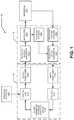
- FIG. 1is a block diagram of an exemplary control system for a fluid-based engineering system.
- FIG. 2is a block diagram of an exemplary engine parameter on-board synthesis (EPOS) module of the control system of FIG. 1 .
- EPOSengine parameter on-board synthesis
- FIG. 3is a block diagram of an exemplary CAM input object of the EPOS of FIG. 2 .
- FIG. 4is a block diagram of an exemplary compact aero-thermal (CAM) object of the EPOS of FIG. 2 .
- FIG. 5is a block diagram of an exemplary open-loop model of the CAM object of FIG. 4 .
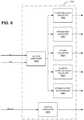
- FIG. 6is a block diagram of an exemplary output conditioning module of the EPOS of FIG. 2 .
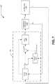
- FIG. 7is a block diagram of an exemplary control configuration for monitoring and controlling material temperatures using the control system of FIG. 1
- FIG. 8is a flowchart representative of a method for controlling material temperature using the control configuration of FIG. 7 .
- FIG. 9is a flowchart representative of machine readable instructions that may be executed to implement the example EPOS of FIGS. 1 and/or 2 .
- FIG. 10is a flowchart representative of machine readable instructions that may be executed to implement the example CAM object of FIGS. 2 and/or 4 .
- FIG. 11is a block diagram of an example processing system that may execute the example machine readable instructions of FIGS. 7-8 and/or any elements of the present disclosure herein.
- Control demandsmay be generated by an operator interface 140 and may be received by the engine parameter on board synthesis (EPOS) 110 .
- the operator interface 140may be a real-time interface such as a cockpit navigation system and/or an operator workstation. Additionally or alternatively, the operator interface 140 may include another, more generalized process control interface, which is suitable for logging control commands to software control components 150 , including, for example, a guidance, navigation, and control computer or autopilot system(s).
- control demandsmay be generated by an internal memory or any other internal programming operatively associated with software control elements 150 .
- the control elements 150may include EPOS 110 and a control law 111 that may generate and/or process control instructions for the apparatus 130 .
- the EPOS 110 and control law 111may be implemented as software modules designed to monitor, control, or otherwise act in associative function with regards to an apparatus 130 .
- the control law 111may obtain control feedbacks from the EPOS 110 and control commands from the operator interface 140 .
- the control law 111may generate control requests in engineering units to be processed by hardware control elements 120 to control the apparatus 130 .
- the software control components 150may include an output conditioner 113 and/or an input conditioner 115 to process output and/or input data for the data's respective input/output destination.
- the input to the EPOS 110provided by the input conditioner 115 , may be processed by fault detection and accommodation (FDA) logic 117 to detect range faults as well as in-range failures (e.g., rate-limit, cross-channel mismatch, etc.) and provide a reasonable input value along with a health status indication for the input.
- FDAfault detection and accommodation
- the hardware control components 120may convert digital data generated by the software control components 150 to an analog form readable by the apparatus 130 (e.g., electrical signals), convert analog data generated by the apparatus 130 into digital data readable software components 150 , condition such input and output data for readability, and/or control actuators 124 associated with the apparatus 130 .
- the digital-to-analog convertor 122can transform digital signals generated by the control law 111 into actuator requests.
- the actuators 124may be one or more devices which use control hardware to position various control components of the apparatus 130 in accordance with instructions generated by the EPOS 110 . Actuators, such as the actuators 124 , may be designed to provide quick and accurate control of an apparatus.
- Actuator sensors 125may be included to measure various states of the actuators 124 , wherein the actuator states (or positions) may be related to the physical configuration of the various control components of the apparatus 130 .
- fluid-based systemsoften include actuators whose linear or angular positions are sensed by actuator sensors 124 , and which are related to the physical position of control surfaces or other control devices located proximate to a compressor, combustor, turbine and/or nozzle/exhaust assembly.
- the hardware control components 120may include apparatus system sensors 126 .
- the apparatus system sensors 126may measure operational parameters associated with the apparatus 130 .
- fluid-based systemsmay include apparatus system sensors 126 that measure the working fluid pressure, temperature and fluid flow at various axial and radial locations in the flow path.
- Apparatus system sensors 126may comprise a variety of different sensing devices, including, but not limited to, temperature sensors, flow sensors, vibration sensors, debris sensors, current sensors, voltage sensors, level sensors, altitude sensors and/or blade tip sensors.
- Apparatus system sensors 126may be positioned to measure operational parameters related to the function of apparatus 130 , e.g., parameters related to control commands submitted to EPOS 110 and control requests generated by EPOS 110 in order to direct actuators 124 to control apparatus 130 .
- Both the apparatus system sensors 126 and the actuator sensors 125may produce electrical signals based upon a read-out result from said sensors.
- the electrical signals produced by the actuator sensors 125 and the apparatus system sensors 126may be transmitted to an analog-to-digital convertor 123 .
- the analog-to-digital convertormay convert the electrical signals into digital signal data which may be compatible with and read by the EPOS 110 after processing by the input conditioning module 115 .
- the apparatus 130may be any fluid-based engineering system.
- Example fluid-based engineering systemsmay include gas turbine engines for aviation and power generation, HVAC&R (heating, ventilation, air-conditioning and refrigeration), fuel cells, and other, more generalized fluid processing systems for hydrocarbon extraction, materials processing, and manufacture.
- the physical components of apparatus 130include, but are not limited to including, compressors, combustors, turbines, shafts, spools, fans, blowers, heat exchangers, burners, fuel cells, electric motors and generators, reactor vessels, storage vessels, fluid separators, pipes, ducts, valves, mixers and other fluid processing or flow control devices.
- the apparatus 130may perform a thermodynamic cycle on a working fluid in order to generate rotational energy, electrical power or reactive trust, to provide heating, ventilation, air conditioning and refrigeration, or to perform other fluid processing functions.
- the range of available cyclesincludes, but is not limited to, the following cycles and their derivatives: Otto cycles, Diesel cycles, Brayton turbine (or first Ericsson) cycles, Brayton jet (Barber/Joule) cycles, Bell-Coleman (reverse Brayton) cycles, Ericsson (Second Ericsson) cycles, Lenoir (pulse-jet) cycles, and Carnot, Stoddard and Stirling cycles.
- apparatus 130may perform a number of individual thermodynamic processes for heating, cooling, flow control, or for processing applications in agriculture, transportation, food and beverage production, pharmaceutical production, or manufacturing, or for the extraction, transportation or processing of a hydrocarbon fuel.
- the range of available thermodynamic processesincludes, but is not limited to, adiabatic, isothermal, isobaric, isentropic, and isometric (isochoric or isovolumetric) transformations, exothermic reactions, endothermic reactions and phase changes.
- the apparatus 130is a gas turbine engine.
- the monitored aspects of the apparatus 130may include, but are not limited to, a compressor, combustor, turbine and/or nozzle/exhaust assembly.
- the input and output values received/generated by the EPOS 110may be vectors representing values for positions (i.e., nozzle areas, variable vane angles, flow path areas, etc.), states, and actual sensed values of parameters (i.e., spool speeds, gas path temperatures, pressures proximate to components, flow rates proximate to components, etc.) related to the components of a gas turbine engine (i.e., a compressor, combustor, turbine and/or nozzle/exhaust assembly, etc.).
- the data processed by the EPOS 110are vectors containing parameters related to functions of the apparatus 130 .
- Example input vectors for the EPOS 110may include an external inputs vector (U E ) and a corrector truth vector (Y Ct ).
- U Emay contain values for external inputs to be processed by the EPOS 110 .
- U Emay describe the configurations, positions and states of various control elements in the apparatus 130 .
- individual elements of external inputs vector U Emay have a set of values related to effector position; these effector position values may describe fuel flow rates, nozzle areas, variable vane angles, flow path orifice areas, and other control element parameters.
- U Emay have a set of values related to boundary conditions related to the operation of apparatus 130 .
- boundary conditionsmay be directly measured by apparatus system sensors 126 , such as fluid temperatures, pressures and flow rates at physical boundaries of apparatus 130 .
- the boundary conditionsmay include boundary flow conditions and inlet and outlet locations.
- Other boundary conditions specific to aircraft applicationsinclude, but are not limited to, flight velocity, altitude, and bleed or power extractions parameters.
- the corrector truth vector Y Ctmay contain data associated with real time execution of the control system and describe the actual (sensed) values of the parameters related to the operation of apparatus 130 .
- the elements of Y Ctmay be based on measurements taken by the actuator sensors 125 and/or the apparatus system sensors 126 . Further, elements of Y Ct may be based on values derived from a well-understood and trusted model of sensed parameters; for example, a flow rate model based on a differential pressure drop across a Pitot tube or Venturi tube.
- Y Ct vector elementsinclude, but are not limited to, spool speeds, gas path temperatures, and/or pressures all values of which may be proximate to engine components such as compressors, combustors, and turbines.
- Y Ctmay correspond to high fidelity data which can either be physically tested or model-based.
- FIG. 2illustrates an embodiment of the EPOS 110 of FIG. 1 in further detail.
- the EPOS 110 of FIG. 2may include, but is not limited to including a CAM input object 220 , a compact aero-thermal model (CAM) object 230 , and a CAM output object 240 .
- the EPOS 110may receive raw input data related to vectors U ERaw and Y CtRaw .
- U ERawmay contain values obtained from the actuator sensors 125 , the apparatus system sensors 126 and/or any other associated sensors and/or inputs.
- Y CtRawmay contain values obtained from the actuator sensors 125 , the apparatus system sensors 126 and/or any other associated sensors and/or inputs.
- the CAM input object 220may package selected values from the received input U E vector into an input vector U E_in . Similarly, the CAM input object 220 may package selected values from the received input into an input corrector truth vector, Y Ct_in . Further, the vectors U E_in and Y Ct_in may then be conditioned to protect the input values; this may be done by range limiting the values, by constraining the values based on instructions, and/or by performing any additional input modifications function on the vectors. The CAM input object 220 may also use the input vectors received to determine an operating mode (OpMode) for the FADEC 110 . The input conditioning module 220 may output a conditioned external input vector U E , a conditioned truth vector Y Ct , and an OpMode vector.
- OpModeoperating mode
- the input validity of the vector valuesmay be ensured by fault detection and accommodation logic (e.g., through processing from the FDA logic 117 ) specific to each sensor input of the CAM input object 220 .
- the fault detection and accommodation logicdetects range faults as well as in-range failures (i.e., rate-limit, cross-channel mismatch, etc.) and provides a reasonable value in all cases along with a health status indication.
- An example CAM input object 220is described in greater detail below with reference to FIG. 3 .
- the output of CAM input object 220is received by the CAM object 230 .
- the CAM object 230may contain aero-thermal representations, or component modules, of engine components.
- the component modules within the CAM object 230may operate according to the system's constraints related to mathematical abstractions of physical laws that govern behavior of the apparatus 130 (i.e., laws of conservation of energy, conservation of mass, conservation of momentum, Newton's 2 nd law for rotating systems, and/or any additional known calculable physics model).
- the system constraints for each contained module within the CAM object 230may have specific constraints programmed within to simulate a monitored area and/or function of the apparatus 130 (i.e., a bypass duct bleeds module, a low spool compressor module, a burner module, a parasitic power extraction module, etc.).
- the CAM object 230may use the input vectors along with internal solver states, representing on-board corrector states, solver states, and physics states, while functioning.
- the solver statesmay be introduced to address fast dynamics, resolve algebraic loops and smooth highly non-linear model elements.
- the CAM object 230may output a synthesized parameters vector Y.
- the vector Ymay be estimated in relation to the operating range determined by the CAM object 230 .
- An example CAM object 230is described in greater detail below with reference to FIG. 4 .
- the output of the CAM object 230may be received by the CAM output object 240 .
- the CAM output object 240may post-process select CAM outputs that are needed by consuming control software and/or hardware. For some outputs, the CAM output object 240 may perform a unit conversion, may apply a test adder, and/or may perform interpolation between ambient conditions and/or CAM output during starting operation.
- the CAM output object 240may unpack the Y vector into values specific values desired by related components (i.e., temperatures, pressures, flows, sensor temperatures, and/or other output synthesis).
- the CAM output object 240may also output inter-component station flows, temperatures, pressures, and/or fuel to air ratios, torque, thrust, bleed flows, and/or compressor and turbine case clearances.
- the CAM output object 240may also indicate the current status (e.g., the aforementioned “OpMode” operating mode) as determined by the EPOS 110 .
- An example CAM output object 240is described in greater detail below with reference to FIG. 6 .
- FIG. 3illustrates an exemplary embodiment of the CAM input object 220 of FIG. 2 .
- the CAM input object of FIG. 3may include a U E vector packager 310 , a Y Ct vector packager 320 , an OpMode Determiner 330 , and an input protection module 340 .
- the U E vector packagermay receive vector U ERaw and the U E vector packager 310 may select the desired values from the input vectors and may create vector U E_in , which may be output to the input protection module 340 .
- the U E vector packager 310may also be used for unit conversion and for synthesizing values for U E which may not be present.
- the Y Ct vector packagermay receive vector Y CtRaw .
- the Y Ct vector packager 310may select the desired values from the input vectors and may create vector Y Ct_in , which may be output to the input protection module 340 .
- the OpMode determiner 330may establish the operating mode of the CAM object 230 based on the health status of input values that are necessary to run in each operating mode.
- the health statusmay include status of control sensors determined by the FDA logic 117 , as well as internally generated information by the CAM object 230 , such as conditions of internal states and outputs.
- the OpMode determiner 330may operate using a logic design that seeks the highest fidelity mode based on available inputs and may fall back to decreased fidelity modes to accommodate faults.
- the operating mode determined by the OpMode determiner 330is one of a programmed list of operating modes related to the function of the apparatus 130 and based on the input vector values and/or the condition of CAM states and/or outputs. The functions of various downstream elements may be affected by the resulting operating mode determined by the OpMode determiner 330 .
- the input protection module 340uses the OpMode vector and the input from the vector packagers 310 , 320 to determine input vectors U E and Y Ct . Said vectors are received by the CAM object 230 , illustrated in greater detail in FIG. 4 .
- the CAM object 230may generate state vectors X C , X S , and X P .
- the physics state vector (X P )contains simulated parameters related to dynamics of the apparatus 130 during a time of interested, whose derivatives (X pDot ) are calculated in an open loop model 410 .
- the vector X Pmay include, but is not limited to including, spool shaft speeds, apparatus material temperatures, etc.
- the solver state vector X Smay contain values related to adjustments that are made to certain components of the apparatus 130 . These values may be adjustments to make up for errors coming from the CAM.
- the X C vectormay contain values related to on-board corrector states, which are simulated component level values that are a refinement of the Y Ct vector to make the modeled Y C vector comparable to the real values of Y Ct .
- the CAM object 230may fully execute each dynamic pass of the simulation, each pass being denoted by letter k.
- the product of each simulation pass k and simulation time step dtis the simulation time.
- the set state module 420may receive input of the U E , Y Ct , and OpMode vectors. Additionally, the set state module 420 may receive the prior state's values of the X vectors generated by the estimate state module 440 . In FIG. 4 , the prior state is denoted by the state “(k ⁇ 1).” The set state module 420 may override the states in the X vectors with a base point value; however, if the values do not need an override, the set state module 420 may act as a pass through element.
- the override functions of the set state module 420may override the values within the X vectors with base-point (U) or external (Y Ct ) values depending on the operating mode (OpMode) input to the CAM Module 230 .
- the set state module 420may look up base-point values for CAM states for use during initialization.
- the set state module 420may also select an active subset of solver states.
- the set state module 420may generate corrector state (X C ), solver state (X S ), and physics state (X P ) vectors for use in the open loop model 410 .
- the open loop model 410may consist of one or more cycle synthesis modules, each cycle synthesis module relating to a component, function, and/or condition associated with the apparatus 130 .
- the open loop model 410is composed of a variety of cycle synthesis modules that may represent components, functions and/or conditions associated with a cycle of apparatus 130 .
- the open loop moduleis not limited to any specific number of modules and may contain any number of modules that are used to simulate components, functions, and/or conditions associated with apparatus 130 .
- the open loop model 410may receive input of the corrector state (X C ), solver state (X S ), and physics state (X P ) vectors from the set state module 420 and the effector/boundary condition vector (U E ).
- the values input to the open loop model 410may be used as input to the various modules simulating the components of apparatus 130 .
- the open loop model 410uses the values generated by the cycle synthesis modules to form a synthesized parameters vector Y(k) based on U E (k) and X(k).
- the synthesized parameters vector Y(k)contains synthesized cycle values determined from the simulated physics of the open loop module 410 and may be used for control of the apparatus 130 .
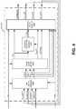
- FIG. 5illustrates an example embodiment of open loop model 410 of FIG. 4 .
- the open loop model 410may include a group of primary stream modules 510 , a group of secondary stream modules 520 , a group of additional modules 530 and a vector data packager 540 .
- the open loop model 410may receive input of the corrector state (X C ), solver state (X S ), and physics state (X P ) vectors, from the set state module 420 , and the effector vector (U E ).
- the group of primary stream modules 510 , the group of secondary stream modules 520 , and the additional modules 530all may receive input from the corrector state (X C ), solver state (X S ), and physics state (X P ) vectors from the set state module 420 and the effector vector (U E ).
- the open loop module 410is not limited to including the above mentioned groups of modules, but rather, the open loop module 410 may omit groups of modules and/or include other groups of modules. Any and all modules of the open loop model 410 may interact with one another to produce the output of each module.
- Each module of the open loop module 410may represent a component of the apparatus 130 and may be implemented by a library of utilities, wherein each utility may be a mathematical representation of the physical properties that make up various parts of component calculations.
- utilities of the modulesmay include representations of compressors, turbines, bleeds, pressure losses, etc. that may be reusable throughout the CAM object 230 and may improve readability and maintainability of the EPOS 110 .
- These componentsmay be built from physics representations of aerodynamic and thermodynamic processes.
- Each modulemay produce, for example, an output vector containing, for example, total pressure, total temperature, fuel/air ratio, and gas flow at the exit of the component, and/or any other parameter associated with the modeled portion of the apparatus 130 .
- the primary stream modules 510may include, but are not limited to including, the following based on corresponding elements of the apparatus 130 : a CMP_L module 605 modeling a low spool compressor, a D_BLD_STB 610 module modeling a bleed associated with a low spool compressor, a D_CS_INT module 615 modeling a pressure loss associated with air flow passing through a duct of a compressor, a CMP_H module 620 modeling a high spool compressor, a D_I030 625 module modeling a pressure loss associated with instrumentation in a duct at the exit of a high spool compressor, a D_DIF_BURN module 630 modeling a diffuser, a BRN_PRI module 635 modeling a burner, a TRB_H module 640 modeling a high spool turbine, a TRB_L module 645 modeling a low spool turbine, a D_EGV_LT module 650 modeling a low turbine exit guide vane duct,
- the secondary stream modules 520may include, but are not limited to including, the following based on corresponding elements of the apparatus 130 : an example CMP_F_SEC module 705 modeling a fan outer diameter compressor, a D_EGV_FO module 710 modeling a fan exit guide vane duct, a D_BLD_SEC module 715 modeling an exit duct between a low compressor and a high compressor, a D_AVE_140 module 720 modeling a duct downstream of a B25 bleed, a D_BLD_NOZ_SEC module 725 modeling bypass duct bleeds of the apparatus 130 , a D_I_NOZ_SEC module 730 modeling a secondary nozzle duct, and a NOZ_SEC module 735 modeling a secondary nozzle.
- an example CMP_F_SEC module 705modeling a fan outer diameter compressor
- a D_EGV_FO module 710modeling a fan exit guide vane duct
- a D_BLD_SEC module 715modeling an exit
- the modules 530may include, but are not limited to including, the following based on conditions of the apparatus 130 : a POWER_EXTRACT module 805 modeling effects of energy and/or efficiency losses of the apparatus 130 , a FAN_ID_POWER module 810 modeling an accounting for power loss from a fan gear box of the apparatus 130 , and a TORQUE_BALANCE module 815 modeling an accounting for conservation of energy related to unsteady torque balance within the apparatus 130 , and a CALC_ERR_SLVR module 820 that forms solutions to errors detected in the OLM 410 . Further, any additional modules and/or groups of modules modeling any additional physical properties associated with the apparatus 130 may be included as part of the open loop model 410 .
- the example modules of FIG. 5may be designed using one or more physics-based configurable utilities.
- the configurable utilitiesmay be contained in a library of subsystems within the EPOS structure.
- the open loop module 440may compile the above mentioned modules from the subsystems of physics-based configurable utilities based on preprogrammed instructions and/or a user input.
- the vector data packager 540receives input data from the group of primary stream modules 510 , the group of secondary stream modules 520 , and the additional modules 530 .
- the open loop modelmay also output a solver errors vector (ErrSlvr) related to the solver states vector (X S ).
- the open loop model 410may collect and output a physics state derivatives vector (X PDot ).
- the received datamay be packaged by the vector data packager 540 in the form of vectors Y(k), ErrSlvr, and X PDot . Further, the vector data packager may package vector data into fewer vectors and/or additional vectors.
- Certain utilities used to comprise said modules of the open loop model 410may model gas-based properties and may represent, for example, specific heat as a function of temperature and fuel/air ratio, relative pressure as a function of enthalpy and fuel/air ratio, enthalpy as a function of temperature and fuel/air ratio, specific heat ratio as a function of temperature and fuel/air ratio, relative pressure as a function of temperature and fuel/air ratio, relative pressure as a function of temperature and fuel/air ratio, temperature as a function of enthalpy and fuel/air ratio, and/or gas constant and specific heat ratio as a function of temperature and fuel/air ratio.
- Other example utilitiesmay model thermal conductivity as a function of gas total temperature, the absolute viscosity as a function of gas total temperature, critical flow parameters as a function of specific heat and a gas constant, coefficients of thermal expansion as a function of material temperature and/or type, material specific heat as a function of material temperature and/or type, and/or material thermal conductivity as a function of material temperature and type. Further, other utilities modeling other gas related functions may be present. Additionally or alternatively, any other utilities modeling any other properties associated with the apparatus 130 may be included.
- the utilitiesmay include one or more heat transfer utilities for determining the temperature and/or rate of change in temperature of various materials associated with elements of the apparatus 130 modeled by respective cycle synthesis modules.
- the heat transfer utilitiesmay generate an estimated material temperature (T m ) and/or an estimated material temperature rate of change (T mDot ) associated with said material(s).
- the modules comprising the open loop model 410may include one or more configurable utilities.
- the configurable utilitiesmay be complex representations of engine components.
- a configurable utilitymay represent a particular physical effect in major engine components such as a compressor or a turbine.
- Each instance of a configurable utilitymay be selected to be one of several representations of the physical processes it models, even though the interface of the configurable model remains unchanged.
- Configurable utilitiesmay reconfigure themselves to represent a particular component by switching the underlying configurable subsystems. Using such configurable utilities may benefit the maintainability of a software application of the open loop model 430 .
- a configurable utilitymay be designed to model a Reynolds effect in the compressors of the apparatus 130 and may reconfigure itself to represent a particular component of the compressor (e.g., a high spool compressor, a low spool compressor, etc.).
- This example configurable, compressor Reynolds effect utilitymay be used in formation of cycle synthesis modules and may be used in modules simulating a low spool compressor (e.g., the CMP_L module 605 of FIG. 5 ), a high spool compressor (e.g., the CMP_H module 620 of FIG. 5 ), and/or any other module associated with a compressor simulation.
- specific modules of the open loop model 410may utilize a configurable utility to model Reynolds effect in the turbines of the apparatus 130 and may reconfigure itself to represent a particular component of the compressor.
- a specific utilitymay model physical processes of a compressor of the apparatus 130 and may include representations of such physical processes as sub-utilities.
- Sub-utilities of an example compressor utilitymay include, but is not limited to including, basic physics utilities associated with the basic physics of the apparatus 130 (e.g., isentropic compression, laws of thermodynamics, ideal gas properties, etc.), a component aero-thermal map evaluation, gas-material heat transfer properties, models of component bleeds, torque components from adiabatic steady-state, and/or effects of scaling between map and cycle conditions (design, gas property, Reynolds effect, clearance, untwisting effects, etc.).
- the output of such a compressor utilitymay include, but is not limited to including, component exit gas flow conditions, bleed flows, swirl angles, total component inlet gas flows, torque extracted, and derivatives of material temperatures.
- a compressor utilitymay be operatively associated with other utilities (e.g., off-board correction look up tables with selectable scheduling parameters, a selector for enabling on-board and/or off-board correction for the component, etc.) to form a compressor-related module like, for example, the CMP_L module 605 and/or the CMP_H module 620 .
- Sub-utilities of an example turbine utilitymay include, but are not limited to including, basic physics utilities associated with the basic physics of the apparatus 130 (e.g., isentropic expansion, laws of thermodynamics, ideal gas properties, etc.), a component aero-thermal map evaluation, gas-material heat transfer properties, models of inlet guide vanes, models of consolidated turbine cooling bleeds, rotor inlet temperature calculation, turbine clearance effects, and/or effects of scaling between map and cycle conditions (design, gas property, Reynolds effect, clearance, untwisting effects, etc.).
- Outputs of such an example of turbine utilitiesmay include, but are not limited to including, component exit gas conditions, rotor inlet temperature, flows into the turbine, generated torque, material temperature derivatives, steady state material temperature at current conditions, material temperature time constants, radius of apparatus from thermal expansion, and/or clearance values.
- a turbine utilitymay be operatively associated with other utilities (e.g., off-board correction look up tables with selectable scheduling parameters, a selector for enabling on-board and/or off-board correction for the component, etc.) to form a compressor-related module like, for example, the TRB_H module 640 and/or the TRB_L module 645 .
- the sensing synthesis module 430may model control sensor measurements that differ from corresponding average gas path engine station estimates packaged in Y due to regime/location effects in the sensor surroundings and sensor body thermal inertia. Receiving input of Y and the derivative physics state vector (X PDot ), the sensing synthesis module 430 may act as another means of fault or error detection within the CAM module 230 .
- the estimate state module 440may use said inputs to determine the next pass value of CAM state vector X(k).
- the estimate state module 440may scale and correct solver state error vector, select solver gain scheduling parameters, calculate solver state gains, calculate scale, and correct the corrector state error vector, integrate state derivatives, apply state integrator range limits, reset state integrators during initialization, detect saturated state integrators, and/or detect internal errors indicated by unreasonably large synthesized values.
- the estimate state module 440may receive input of the effector vector (U E ), the synthesized parameters vector (Y), the on-board corrector state vector (X C ), the physics state vector (X P ), the solver state vector (X S ), the solver errors vector (errSlver), and the physics state derivatives vector (X PDot ).
- the estimate state module 440may output updated versions of the on-board corrector state vector (X C_ESM ), the physics state vector (X P_ESM ), and the solver state vector (X S_ESM ). These vectors are the analyzed state vectors from the current iteration of the open loop model 410 .
- the output of the estimate state module 440is received by the CAM output object 240 , which is illustrated in FIG. 6 .
- the CAM output object 240may include, but is not limited to including, a vector unpacker 910 , a temperatures valuator 920 , a pressures valuator 930 , a flows valuator 940 , a sensor temperatures valuator 950 , an other output synthesizer 960 , and a status indicator 970 .
- the vector unpacker 910may receive input of the synthesized parameters vector (Y).
- the vector unpacker 910may output the unpacked Y vector to other elements of the output conditioning module.
- the status indicator 970may receive input of the operating mode vector (OpMode).
- the output conditioning module 240is not limited to including the above mentioned elements, but rather, output conditioning module 240 may omit elements and/or include other elements.
- the temperatures valuator 920may process temperature related values of the synthesized parameters vector (Y). This may include performing unit conversions, implementing test adders, performing non-linear interpolation between temperature values during the starting functions of the apparatus 130 , and/or obtaining temperature values from default tables as backup if/when needed.
- the temperatures valuator 920is not limited to functioning in the above mentioned manner, rather, the temperatures valuator 920 may omit any of the listed functions and/or add additional functions related to processing temperature data of the synthesized parameters vector (Y).
- the pressures valuator 930may process pressure related values of the synthesized parameters vector (Y). This may include performing unit conversions, implementing test adders, performing non-linear interpolation between pressure values during the starting functions of the apparatus 130 , and/or obtaining pressure values from default tables as backup if/when needed.
- the pressures valuator 930is not limited to functioning in the above mentioned manner, rather, the pressures valuator 930 may omit any of the listed functions and/or add additional functions related to processing pressure data of the synthesized parameters vector (Y).
- the flows valuator 940may process fuel flow related values of the synthesized parameters vector (Y). This may include performing unit conversions, implementing test adders, performing non-linear interpolation between fuel flow values during the starting functions of the apparatus 130 , and/or obtaining fuel flow values from default tables as backup if/when needed.
- the flows valuator 940is not limited to functioning in the above mentioned manner, rather, the flows valuator 940 may omit any of the listed functions and/or add additional functions related to processing fuel flow data of the synthesized parameters vector (Y).
- the sensor temperatures valuator 950may process sensor temperature related values of the synthesized parameters vector (Y). This may include performing unit conversions, implementing test adders, performing non-linear interpolation between temperature values during the starting functions of the apparatus 130 , and/or obtaining sensor temperature values from default tables as backup if/when needed.
- the sensor temperatures valuator 950is not limited to functioning in the above mentioned manner, rather, the sensor temperatures valuator 950 may omit any of the listed functions and/or add additional functions related to processing sensor temperature data of the synthesized parameters vector (Y).
- the other output synthesizer 960may process other output data of the synthesized parameters vector (Y) not processed by the temperatures valuator 920 , the pressures valuator 930 , the flows valuator 940 , the sensors and/or the temperatures valuator 950 . This may include performing unit conversions, implementing test adders, performing non-linear interpolation between temperature values during the starting functions of the apparatus 130 , and/or obtaining other output values from default tables as backup if/when needed.
- the flows valuator 940is not limited to functioning in the above mentioned manner, rather, the flows valuator 940 may omit any of the listed functions and/or add additional functions related to processing other output data of the synthesized parameters vector (Y).
- the status indicator 970may receive input from the operating mode vector (OpMode). Using this input, the status indicator 970 may generate and provide a status indication of the operating status of the CAM module 230 for use in any downstream logic devices.
- OpModeoperating mode vector
- the control system 100may be implemented to monitor and/or control the temperatures of materials of the apparatus 130 within a given flow path of the apparatus 130 .
- An aim of the control system 100is to maximize the apparatus 130 performance while reducing wear on components caused by excess material temperatures of the materials of said components. For example, high temperatures at a burner of an apparatus may increase cycle thermal efficiency but may cause excessive material temperature of the material in engine components. Therefore, limiting the fuel flowing to a burner may reduce the temperatures at a given material.
- the control system 100may be employed for material temperature control.
- the CAM-based EPOS 110receives effector positions and boundary conditions (U fb ) from the apparatus 130 via the hardware control components 120 . Additionally, the EPOS 110 may receive engine/cycle measurements (Y m ) from the apparatus 130 , via one or more sensors and/or other hardware input. Using the input, the EPOS generates a model output for control.
- the EPOS 110may determine a value for the temperatures (T m ) and rate of change in temperatures (T mDot ) for a given apparatus material using the model output.
- the apparatus materialmay be, for example, material surfaces associated with turbomachinery, such as a surface of a turbine case.
- the software control elements 150may also determine goal values for temperatures (T mGoal ) and rate of change in temperatures (T mDotGoal ). The goal values may be produced by the EPOS 110 and/or the goal values may be determined using input generated from the operator interface 140 .
- the generated values of T m , T mDot , T mGoal , and T mDotGoalmay be used to determine advanced multi-variable control (AMVC) instructions 165 for output to the control hardware.
- the AMVC instructions 165may be generated by the control law 111 .
- control error (errCtrl) processingmay be applied to the input of the AMVC 165 .
- the AMVC instructions 165are used by hardware control elements 150 , such as the actuators 124 ), to generate a control request (U fb ) for the apparatus 150 .
- the control requestsmay be used to control and monitor material temperatures as described in the flowchart 980 of FIG. 8 .
- the model output of the EPOS 110may generate an estimated material temperature (T m ) and/or an estimated material temperature rate of change (T mDot ) (both values contained in the X f vector) for a given component of the apparatus 130 (as modeled by a respective cycle synthesis module).
- T m and T mDot valuesmay be determined during computations by the open loop model 410 , wherein specific cycle synthesis modules pertaining to material temperature-effected materials may produce the values.
- the cycle synthesis modulesmay employ a utility from the series of utilities (e.g., a “material temperature utility”) which determines T m and/or T mDot for a material of a given element modeled by its respective cycle synthesis module.
- the control lawmay receive a material temperature signal; the material temperature signal may include the values for T m and/or T mDot .
- the control law 111may determine controls for the flow along the gas path of the apparatus at a specified element based on the material temperature signal (block 986 ). Determinations for the controls output by the control law 111 may be based on goal values for material temperature and/or goal values for the material temperature rate of change. Additionally or alternatively, the controls output may be based on other preprogramming and/or user input.
- the actuator 124may receive input based on the model output, the model output including the material temperature signal based on the material temperature of at least one component of the cycle of the control system ( 988 ).
- the input received by the actuatormay be used to govern effector boundary conditions and, for example, regulate a fuel flow to the apparatus 130 .
- FIGS. 2-6While an example manner of implementing the EPOS 110 of FIG. 1 has been illustrated in FIGS. 2-6 , one or more elements, processes, and/or devices illustrated in FIGS. 2-6 may be combined, divided, rearranged, omitted, eliminated and/or implemented in any other way. Further, the example elements of FIGS. 1-6 could be implemented by one or more circuit(s), programmable processor(s), application specific integrated circuit(s) (ASIC(s)), programmable logic device(s) (PLD(s)) and/or field programmable logic device(s) (FPLD(s)), etc.
- ASICapplication specific integrated circuit
- PLDprogrammable logic device
- FPLDfield programmable logic device
- FIGS. 9 and 10Flowcharts representative of example machine readable instructions are shown in FIGS. 9 and 10 .
- the machine readable instructionscomprise a program for execution by a processor such as the processor such as the processor 1210 shown in the example computer 1200 discussed below in connection with FIG. 11 .
- the programmay be embodied in software stored on a tangible computer readable medium such as a CD-ROM, a floppy disk, a hard drive, a digital versatile disk (DVD), a Blu-ray disk, or a memory associated with the processor 1210 , but the entire program and/or parts thereof could alternatively be executed by a device other than the processor 1210 and/or embodied in firmware or dedicated hardware.
- the example programsare described with reference to the flowcharts illustrated in FIGS. 9 and 10 , many other methods of implementing embodiments of the present disclosure may alternatively be used. For example, the order of execution of the blocks may be changed, and/or some of the blocks described may be changed, eliminated, or combined.
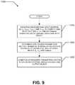
- example machine readable instructions 1000may be executed to implement the EPOS 110 of FIGS. 1 and/or 2 .
- the example machine readable instructions 1000begin execution at block 1010 at input vectors are received by the CAM input object 220 and are used by the CAM input object 220 to determine the operating mode (OpMode) of the simulation and to compile the CAM input vectors U E and Y Ct (block 1015 ).
- the CAM input vectorsare then used by the CAM object 230 to determine synthesized parameters vector Y based on internal physics state module of the CAM module 230 and the external inputs U E , Y Ct , and OpMode (block 1020 ).
- the synthesized parameters vector Yis conditioned by the CAM output object 240 for use by external modules such as, for example, the control law 111 of FIG. 1 (block 1025 ).
- the example machine readable instructions 1100 of FIG. 10may be executed to implement the CAM object 230 of FIGS. 2 and/or 4 .
- the set state modulereceives input from and sets the state of the CAM object 230 based upon vectors U E , Y C (k), OpMode, and prior physics state vectors generated by the estimate state module 440 in the form of X E_ESM (k ⁇ 1), X C_ESM (k ⁇ 1), and X P_ESM (k ⁇ 1) (block 1110 ).
- the open loop model 410determines synthesized parameters vector Y(k) by processing data contained in U E , Y C (k), X C (k ⁇ 1), X S (k ⁇ 1), and X P (k ⁇ 1) using one or more contained cycle synthesis modules, the one or more cycle synthesis modules being a mathematical abstraction(s) of the physics states associated with an element of a cycle of the apparatus 130 (block 1115 ).
- the sensing synthesis module 430receives the synthesized parameters vector Y(k) and detects potential errors in the vector (block 1120 ).
- the estimate state module 440determines the physics state vectors X S_ESM (k), X C_ESM (k), and X P_ESM (k) for the present state (k) (block 1125 ).
- the estimate state module 440outputs the vectors X S_ESM (k), X C_ESM (k), and X P_ESM (k) to the set state module 420 for processing the next sequential state (block 1130 ).
- the estimate state module 440outputs the vector Y(k) for use external to the CAM module 230 (block 1135 ).
- FIG. 11is a block diagram of an example computer 1200 capable of executing the instructions of FIGS. 8-9 to implement the apparatus of FIGS. 1-7 .
- the computer 1200can be, for example, a server, a personal computer, or any other type of computing device.
- the system 1200 of the instant exampleincludes a processor 1210 .
- the processor 1210can be implemented by one or more microprocessors or controllers from any desired family or manufacturer.
- the processor 1210includes a local memory 1215 and is in communication with a main memory including a read only memory 1230 and a random access memory 1220 via a bus 1240 .
- the random access memory 1220may be implemented by Synchronous Dynamic Random Access Memory (SDRAM), Dynamic Random Access Memory (DRAM), RAMBUS Dynamic Random Access Memory (RDRM) and/or any other type of random access memory device.
- SDRAMSynchronous Dynamic Random Access Memory
- DRAMDynamic Random Access Memory
- RDRMRAMBUS Dynamic Random Access Memory
- the read only memory 1230may be implemented by a hard drive, flash memory and/or any other desired type of memory device.
- One or more input devices 1254are connected to the interface circuit 1250 .
- the input device(s) 1254permit a user to enter data and commands into the processor 1210 .
- the input device(s)can be implemented by, for example, a keyboard, a mouse, a touchscreen, a track-pad, a trackball, isopoint and/or a voice recognition system.
- the interface 1250may operate in conjunction with, in parallel with, or in place of, the operator interface 115 of FIG. 1 .
- One or more output devices 1258are also connected to the interface circuit 1250 .
- the output devices 1258can be implemented by, for example, display devices for associated data (e.g., a liquid crystal display, a cathode ray tube display (CRT), etc.), and/or an actuator operatively associated with a fluid-based engineering system such as gas turbine engines for aviation and power generation, HVAC&R (heating, ventilation, air-conditioning and refrigeration), fuel cells, and other, more generalized fluid processing systems for hydrocarbon extraction, materials processing, and manufacture.
- a fluid-based engineering systemsuch as gas turbine engines for aviation and power generation, HVAC&R (heating, ventilation, air-conditioning and refrigeration), fuel cells, and other, more generalized fluid processing systems for hydrocarbon extraction, materials processing, and manufacture.
- Example fluid-based engineering systemsmay include gas turbine engines for aviation and power generation, HVAC&R (heating, ventilation, air-conditioning and refrigeration), fuel cells, and other, more generalized fluid processing systems for hydrocarbon extraction, materials processing, and manufacture.
- HVAC&Rheating, ventilation, air-conditioning and refrigeration
- compact aero-thermal models of fluid-based engineering systemsmay be designed to reduce computational load on a system's control device and/or on board processor. The efficiency of such a model may be improved through the use of a series of utilities, the utilities based on mathematical abstractions of physical properties associated with components of the engineering system. This improvement over the prior art may conserve computational efficiency and may improve the accuracy of the control system for fluid-based engineering systems.
Landscapes
- Engineering & Computer Science (AREA)
- Physics & Mathematics (AREA)
- Chemical & Material Sciences (AREA)
- Combustion & Propulsion (AREA)
- General Engineering & Computer Science (AREA)
- Mechanical Engineering (AREA)
- General Physics & Mathematics (AREA)
- Automation & Control Theory (AREA)
- Fluid Mechanics (AREA)
- Evolutionary Computation (AREA)
- Artificial Intelligence (AREA)
- Computer Vision & Pattern Recognition (AREA)
- Health & Medical Sciences (AREA)
- Mathematical Physics (AREA)
- Medical Informatics (AREA)
- Software Systems (AREA)
- Feedback Control In General (AREA)
- Control Of Turbines (AREA)
- Turbine Rotor Nozzle Sealing (AREA)
- Fluid-Pressure Circuits (AREA)
- Fuel Cell (AREA)
Abstract
Description
Claims (20)
Priority Applications (1)
| Application Number | Priority Date | Filing Date | Title |
|---|---|---|---|
| US16/205,351US10844793B2 (en) | 2013-03-15 | 2018-11-30 | Compact aero-thermo model based engine material temperature control |
Applications Claiming Priority (4)
| Application Number | Priority Date | Filing Date | Title |
|---|---|---|---|
| US201361800440P | 2013-03-15 | 2013-03-15 | |
| PCT/US2014/027979WO2014143837A1 (en) | 2013-03-15 | 2014-03-14 | Compact aero-thermo model based engine material temperature control |
| US201514768002A | 2015-08-14 | 2015-08-14 | |
| US16/205,351US10844793B2 (en) | 2013-03-15 | 2018-11-30 | Compact aero-thermo model based engine material temperature control |
Related Parent Applications (2)
| Application Number | Title | Priority Date | Filing Date |
|---|---|---|---|
| US14/768,002ContinuationUS10161313B2 (en) | 2013-03-15 | 2014-03-14 | Compact aero-thermo model based engine material temperature control |
| PCT/US2014/027979ContinuationWO2014143837A1 (en) | 2013-03-15 | 2014-03-14 | Compact aero-thermo model based engine material temperature control |
Publications (2)
| Publication Number | Publication Date |
|---|---|
| US20190107057A1 US20190107057A1 (en) | 2019-04-11 |
| US10844793B2true US10844793B2 (en) | 2020-11-24 |
Family
ID=51537519
Family Applications (16)
| Application Number | Title | Priority Date | Filing Date |
|---|---|---|---|
| US14/770,388Active2037-01-17US10480416B2 (en) | 2013-03-15 | 2014-03-14 | Compact aero-thermo model based control system estimator starting algorithm |
| US14/770,543Active2034-07-10US10145307B2 (en) | 2013-03-15 | 2014-03-14 | Compact aero-thermo model based control system |
| US14/768,002Active2034-09-01US10161313B2 (en) | 2013-03-15 | 2014-03-14 | Compact aero-thermo model based engine material temperature control |
| US14/765,672Active2034-07-20US9915206B2 (en) | 2013-03-15 | 2014-03-14 | Compact aero-thermo model real time linearization based state estimator |
| US14/767,818Active2035-04-26US10196985B2 (en) | 2013-03-15 | 2014-03-14 | Compact aero-thermo model based degraded mode control |
| US14/769,860ActiveUS10087846B2 (en) | 2013-03-15 | 2014-03-14 | Compact aero-thermo model stabilization with compressible flow function transform |
| US14/765,953Active2035-05-04US10190503B2 (en) | 2013-03-15 | 2014-03-14 | Compact aero-thermo model based tip clearance management |
| US14/767,810Active2034-09-06US10107203B2 (en) | 2013-03-15 | 2014-03-14 | Compact aero-thermo model based engine power control |
| US14/767,995Active2034-07-15US10107204B2 (en) | 2013-03-15 | 2014-03-14 | Compact aero-thermo model base point linear system based state estimator |
| US15/899,800ActiveUS10539078B2 (en) | 2013-03-15 | 2018-02-20 | Compact aero-thermo model real time linearization based state estimator |
| US16/143,582ActiveUS10400677B2 (en) | 2013-03-15 | 2018-09-27 | Compact aero-thermo model stabilization with compressible flow function transform |
| US16/162,589ActiveUS10753284B2 (en) | 2013-03-15 | 2018-10-17 | Compact aero-thermo model base point linear system based state estimator |
| US16/163,687Active2034-04-19US10774749B2 (en) | 2013-03-15 | 2018-10-18 | Compact aero-thermo model based engine power control |
| US16/203,995ActiveUS10767563B2 (en) | 2013-03-15 | 2018-11-29 | Compact aero-thermo model based control system |
| US16/205,351ActiveUS10844793B2 (en) | 2013-03-15 | 2018-11-30 | Compact aero-thermo model based engine material temperature control |
| US17/017,815ActiveUS11078849B2 (en) | 2013-03-15 | 2020-09-11 | Compact aero-thermo model based engine power control |
Family Applications Before (14)
| Application Number | Title | Priority Date | Filing Date |
|---|---|---|---|
| US14/770,388Active2037-01-17US10480416B2 (en) | 2013-03-15 | 2014-03-14 | Compact aero-thermo model based control system estimator starting algorithm |
| US14/770,543Active2034-07-10US10145307B2 (en) | 2013-03-15 | 2014-03-14 | Compact aero-thermo model based control system |
| US14/768,002Active2034-09-01US10161313B2 (en) | 2013-03-15 | 2014-03-14 | Compact aero-thermo model based engine material temperature control |
| US14/765,672Active2034-07-20US9915206B2 (en) | 2013-03-15 | 2014-03-14 | Compact aero-thermo model real time linearization based state estimator |
| US14/767,818Active2035-04-26US10196985B2 (en) | 2013-03-15 | 2014-03-14 | Compact aero-thermo model based degraded mode control |
| US14/769,860ActiveUS10087846B2 (en) | 2013-03-15 | 2014-03-14 | Compact aero-thermo model stabilization with compressible flow function transform |
| US14/765,953Active2035-05-04US10190503B2 (en) | 2013-03-15 | 2014-03-14 | Compact aero-thermo model based tip clearance management |
| US14/767,810Active2034-09-06US10107203B2 (en) | 2013-03-15 | 2014-03-14 | Compact aero-thermo model based engine power control |
| US14/767,995Active2034-07-15US10107204B2 (en) | 2013-03-15 | 2014-03-14 | Compact aero-thermo model base point linear system based state estimator |
| US15/899,800ActiveUS10539078B2 (en) | 2013-03-15 | 2018-02-20 | Compact aero-thermo model real time linearization based state estimator |
| US16/143,582ActiveUS10400677B2 (en) | 2013-03-15 | 2018-09-27 | Compact aero-thermo model stabilization with compressible flow function transform |
| US16/162,589ActiveUS10753284B2 (en) | 2013-03-15 | 2018-10-17 | Compact aero-thermo model base point linear system based state estimator |
| US16/163,687Active2034-04-19US10774749B2 (en) | 2013-03-15 | 2018-10-18 | Compact aero-thermo model based engine power control |
| US16/203,995ActiveUS10767563B2 (en) | 2013-03-15 | 2018-11-29 | Compact aero-thermo model based control system |
Family Applications After (1)
| Application Number | Title | Priority Date | Filing Date |
|---|---|---|---|
| US17/017,815ActiveUS11078849B2 (en) | 2013-03-15 | 2020-09-11 | Compact aero-thermo model based engine power control |
Country Status (4)
| Country | Link |
|---|---|
| US (16) | US10480416B2 (en) |
| EP (9) | EP2973524A4 (en) |
| JP (9) | JP6453302B2 (en) |
| WO (9) | WO2014152701A1 (en) |
Cited By (1)
| Publication number | Priority date | Publication date | Assignee | Title |
|---|---|---|---|---|
| US20230090879A1 (en)* | 2021-08-20 | 2023-03-23 | Raytheon Technologies Corporation | On-board estimator effector drift detection in engine control |
Families Citing this family (55)
| Publication number | Priority date | Publication date | Assignee | Title |
|---|---|---|---|---|
| US10480416B2 (en) | 2013-03-15 | 2019-11-19 | United Technologies Corporation | Compact aero-thermo model based control system estimator starting algorithm |
| US20180225409A1 (en)* | 2014-01-14 | 2018-08-09 | Charles C. Solvason | Performance analysis and monitoring of radial turbomachinery |
| US10108762B2 (en)* | 2014-10-03 | 2018-10-23 | International Business Machines Corporation | Tunable miniaturized physical subsurface model for simulation and inversion |
| CN104834228B (en)* | 2015-05-07 | 2018-05-15 | 苏州弗尔赛能源科技股份有限公司 | A kind of simulation model of fuel cell stand-by power supply |
| CN105093931B (en)* | 2015-06-08 | 2018-02-02 | 南京航空航天大学 | Design method for nonlinear system controller of aircraft engine |
| US10508601B2 (en) | 2016-02-12 | 2019-12-17 | United Technologies Corporation | Auxiliary drive bowed rotor prevention system for a gas turbine engine |
| US10040577B2 (en) | 2016-02-12 | 2018-08-07 | United Technologies Corporation | Modified start sequence of a gas turbine engine |
| US10174678B2 (en) | 2016-02-12 | 2019-01-08 | United Technologies Corporation | Bowed rotor start using direct temperature measurement |
| US10443507B2 (en) | 2016-02-12 | 2019-10-15 | United Technologies Corporation | Gas turbine engine bowed rotor avoidance system |
| US10539079B2 (en) | 2016-02-12 | 2020-01-21 | United Technologies Corporation | Bowed rotor start mitigation in a gas turbine engine using aircraft-derived parameters |
| US9664070B1 (en) | 2016-02-12 | 2017-05-30 | United Technologies Corporation | Bowed rotor prevention system |
| US10436064B2 (en) | 2016-02-12 | 2019-10-08 | United Technologies Corporation | Bowed rotor start response damping system |
| US10125691B2 (en) | 2016-02-12 | 2018-11-13 | United Technologies Corporation | Bowed rotor start using a variable position starter valve |
| US10125636B2 (en) | 2016-02-12 | 2018-11-13 | United Technologies Corporation | Bowed rotor prevention system using waste heat |
| US10508567B2 (en) | 2016-02-12 | 2019-12-17 | United Technologies Corporation | Auxiliary drive bowed rotor prevention system for a gas turbine engine through an engine accessory |
| US10443505B2 (en) | 2016-02-12 | 2019-10-15 | United Technologies Corporation | Bowed rotor start mitigation in a gas turbine engine |
| US10598047B2 (en) | 2016-02-29 | 2020-03-24 | United Technologies Corporation | Low-power bowed rotor prevention system |
| JP6786233B2 (en)* | 2016-03-22 | 2020-11-18 | 三菱パワー株式会社 | Gas turbine characterization device and gas turbine characterization method |
| US10787933B2 (en) | 2016-06-20 | 2020-09-29 | Raytheon Technologies Corporation | Low-power bowed rotor prevention and monitoring system |
| US10358936B2 (en) | 2016-07-05 | 2019-07-23 | United Technologies Corporation | Bowed rotor sensor system |
| US10221774B2 (en) | 2016-07-21 | 2019-03-05 | United Technologies Corporation | Speed control during motoring of a gas turbine engine |
| EP3273006B1 (en) | 2016-07-21 | 2019-07-03 | United Technologies Corporation | Alternating starter use during multi-engine motoring |
| EP3273016B1 (en) | 2016-07-21 | 2020-04-01 | United Technologies Corporation | Multi-engine coordination during gas turbine engine motoring |
| US10384791B2 (en) | 2016-07-21 | 2019-08-20 | United Technologies Corporation | Cross engine coordination during gas turbine engine motoring |
| US10618666B2 (en) | 2016-07-21 | 2020-04-14 | United Technologies Corporation | Pre-start motoring synchronization for multiple engines |
| GB2553806B (en)* | 2016-09-15 | 2019-05-29 | Rolls Royce Plc | Turbine tip clearance control method and system |
| US10400680B2 (en) | 2016-09-28 | 2019-09-03 | General Electric Company | System and method for synchronizing the operation of airfoil actuators of a gas turbine engine |
| US10787968B2 (en) | 2016-09-30 | 2020-09-29 | Raytheon Technologies Corporation | Gas turbine engine motoring with starter air valve manual override |
| US10065744B2 (en)* | 2016-10-12 | 2018-09-04 | General Electric Company | System and method for using an engine model for multiple functions |
| US10443543B2 (en) | 2016-11-04 | 2019-10-15 | United Technologies Corporation | High compressor build clearance reduction |
| US20180148271A1 (en)* | 2016-11-28 | 2018-05-31 | Bbhs A/S | Conveyor system comprising an aligner for aligning items |
| US10823079B2 (en) | 2016-11-29 | 2020-11-03 | Raytheon Technologies Corporation | Metered orifice for motoring of a gas turbine engine |
| US10801359B2 (en) | 2017-03-14 | 2020-10-13 | General Electric Company | Method and system for identifying rub events |
| US9890908B1 (en)* | 2017-04-18 | 2018-02-13 | Air Products And Chemicals, Inc. | Control system in a gas pipeline network to increase capacity factor |
| CN107121941B (en)* | 2017-06-27 | 2021-04-06 | 贵州大学 | Simulation method and device for stable heating of combined operation of micro gas turbine and heat supply network |
| CN107357176B (en)* | 2017-08-05 | 2020-09-25 | 中国科学院工程热物理研究所 | Modeling method for test run data of aero-engine |
| US10711629B2 (en)* | 2017-09-20 | 2020-07-14 | Generl Electric Company | Method of clearance control for an interdigitated turbine engine |
| CN108104954B (en)* | 2017-12-01 | 2018-12-11 | 中国直升机设计研究所 | A kind of turboshaft engine power rating monitoring method |
| CN108227518B (en)* | 2017-12-29 | 2021-02-26 | 新疆电力建设调试所有限责任公司 | A method and device for correcting a simulation model of a steam turbine |
| US11203950B2 (en) | 2018-01-25 | 2021-12-21 | Raytheon Technologies Corporation | On-board estimator engine sensor fault accommodation in engine control |
| US10557418B2 (en)* | 2018-01-25 | 2020-02-11 | United Technologies Corporation | On-board estimator actuator system fault accommodation in engine control |
| US11319834B2 (en) | 2018-01-25 | 2022-05-03 | Raytheon Technologies Corporation | On-board estimator sensor drift detection in engine control |
| US10822996B2 (en) | 2018-03-12 | 2020-11-03 | General Electric Company | Gas turbine engine health determination |
| US10704413B2 (en)* | 2018-09-06 | 2020-07-07 | Raytheon Technologies Corporation | Systems and methods for variable alignment aerodynamic probes |
| US12180892B2 (en)* | 2019-02-01 | 2024-12-31 | Rtx Corporation | Machine learned aero-thermodynamic engine inlet condition synthesis |
| US11473510B2 (en) | 2019-04-18 | 2022-10-18 | Raytheon Technologies Corporation | Active multi-effector control of high pressure turbine clearances |
| US11125211B2 (en)* | 2019-05-16 | 2021-09-21 | General Electric Company | System and method for wind turbine multivariable control using state dependent quadratic regulator |
| US11667392B2 (en) | 2019-06-20 | 2023-06-06 | Pratt & Whitney Canada Corp. | Method and system for operating a rotorcraft engine |
| US11280496B2 (en) | 2020-03-25 | 2022-03-22 | General Electric Company | Gas turbine engine and methods of controlling emissions therefrom |
| CN111456857B (en)* | 2020-04-04 | 2023-02-28 | 西北工业大学 | A two-degree-of-freedom H∞ controller with decreasing conservative gain scheduling for aeroengines |
| CN111810300B (en)* | 2020-07-03 | 2021-08-06 | 东方电气自动控制工程有限公司 | Gas turbine protection device |
| US11828187B2 (en)* | 2020-10-23 | 2023-11-28 | Pratt & Whitney Canada Corp. | Methods and systems for determining a synthesized engine parameter |
| DE102020213991A1 (en)* | 2020-11-06 | 2022-05-12 | Dürr Systems Ag | Method for operating a treatment facility and treatment facility |
| US12235186B2 (en)* | 2021-10-01 | 2025-02-25 | Pratt & Whitney Canada Corp. | Method of evaluating aircraft engine components for compliance with flow requirements |
| CN120100749B (en)* | 2025-05-07 | 2025-07-29 | 中国航发四川燃气涡轮研究院 | Method for maintaining stability margin of high-pressure compressor of aero-engine |
Citations (89)
| Publication number | Priority date | Publication date | Assignee | Title |
|---|---|---|---|---|
| US4189939A (en) | 1977-12-12 | 1980-02-26 | General Electric Company | Compact multimission aircraft propulsion simulator |
| US4215412A (en) | 1978-07-13 | 1980-07-29 | The Boeing Company | Real time performance monitoring of gas turbine engines |
| US4249238A (en)* | 1978-05-24 | 1981-02-03 | The United States Of America As Represented By The Administrator Of The National Aeronautics And Space Administration | Apparatus for sensor failure detection and correction in a gas turbine engine control system |
| US4313167A (en) | 1979-07-27 | 1982-01-26 | General Electric Company | Thrust control system for a gas turbine engine |
| JPS5781131A (en) | 1980-11-10 | 1982-05-21 | Mitsubishi Heavy Ind Ltd | Starting time fuel control circuit for gas turbine |
| US5010473A (en) | 1989-08-31 | 1991-04-23 | Duke University | Method and apparatus for model-based control of an open-loop process |
| US5202525A (en) | 1990-01-29 | 1993-04-13 | General Electric Company | Scramjet engine having improved fuel/air mixing |
| JPH0544691B2 (en) | 1987-01-21 | 1993-07-07 | Fujitsu Ltd | |
| JPH0693880A (en) | 1992-09-14 | 1994-04-05 | Hitachi Ltd | Gas turbine equipment and operating method thereof |
| US5435694A (en) | 1993-11-19 | 1995-07-25 | General Electric Company | Stress relieving mount for an axial blade |
| JPH0883104A (en) | 1994-09-12 | 1996-03-26 | Toshiba Corp | Plant control equipment |
| US5889205A (en) | 1995-04-10 | 1999-03-30 | Siemens Aktiengesellschaft | Method for determining an air mass flow into cylinders of an internal combustion engine with the aid of a model |
| US5901059A (en) | 1996-09-13 | 1999-05-04 | Honeywell Measurex Corp | Method and apparatus for controlling a process using adaptive prediction feedback |
| US5907949A (en) | 1997-02-03 | 1999-06-01 | United Technologies Corporation | Starting fuel control method for a turbine engine |
| JPH11259947A (en) | 1999-01-08 | 1999-09-24 | Teac Corp | Disk unit |
| JP2001184121A (en) | 1999-12-22 | 2001-07-06 | Mitsubishi Heavy Ind Ltd | Sensor deterioration detection device |
| US6478539B1 (en) | 1999-08-30 | 2002-11-12 | Mtu Aero Engines Gmbh | Blade structure for a gas turbine engine |
| US6487491B1 (en) | 2001-11-21 | 2002-11-26 | United Technologies Corporation | System and method of controlling clearance between turbine engine blades and case based on engine components thermal growth model |
| KR20040033315A (en) | 2001-09-13 | 2004-04-21 | 어드밴스드 마이크로 디바이시즈, 인코포레이티드 | State estimation and scheduling for a manufacturing system |
| US20040088100A1 (en) | 2002-10-31 | 2004-05-06 | Volponi Allan J. | Method for performing gas turbine performance diagnostics |
| US20040093151A1 (en) | 2001-11-16 | 2004-05-13 | Zagranski Raymond D. | Fuel control system for gas turbine engines |
| JP2004162698A (en) | 2002-11-13 | 2004-06-10 | General Electric Co <Ge> | Model-based adaptive control system for controlling gas turbines |
| CN1580496A (en) | 2003-08-13 | 2005-02-16 | 通用电气公司 | Conical tip shroud fillet for a turbine bucket |
| JP2005130658A (en) | 2003-10-27 | 2005-05-19 | Hitachi Ltd | Supply power purchase planning system and supply power purchase planning method |
| JP2005171789A (en) | 2003-12-09 | 2005-06-30 | General Electric Co <Ge> | Method and device for model prediction control of gas turbine for aircraft |
| US20050149274A1 (en) | 2003-12-30 | 2005-07-07 | Finnigan Peter M. | Method and system for active tip clearance control in turbines |
| US20050193739A1 (en) | 2004-03-02 | 2005-09-08 | General Electric Company | Model-based control systems and methods for gas turbine engines |
| JP2005267633A (en) | 2004-03-16 | 2005-09-29 | United Technol Corp <Utc> | Model predictive controller with life extending control |
| US20060013681A1 (en) | 2004-05-17 | 2006-01-19 | Cardarella L J Jr | Turbine case reinforcement in a gas turbine jet engine |
| JP2006057595A (en) | 2004-08-23 | 2006-03-02 | Hitachi Ltd | Gas turbine performance diagnosis system and performance diagnosis method |
| US20060051197A1 (en) | 2004-09-04 | 2006-03-09 | Rolls-Royce Plc | Turbine case cooling |
| US20060212281A1 (en) | 2005-03-21 | 2006-09-21 | Mathews Harry Kirk Jr | System and method for system-specific analysis of turbomachinery |
| EP1749968A2 (en) | 2005-08-03 | 2007-02-07 | United Technologies Corporation | Turbine blades |
| US7215129B1 (en) | 2006-03-30 | 2007-05-08 | General Electric Company | Multi tip clearance measurement system and method of operation |
| US20070118271A1 (en) | 2005-11-18 | 2007-05-24 | General Electric Company | Model-based iterative estimation of gas turbine engine component qualities |
| US20070118270A1 (en) | 2005-11-18 | 2007-05-24 | General Electric Company | Sensor diagnostics using embedded model quality parameters |
| US20080167852A1 (en) | 2006-10-31 | 2008-07-10 | Bartee James F | Nonlinear Model Predictive Control of a Biofuel Fermentation Process |
| US20080178600A1 (en) | 2007-01-26 | 2008-07-31 | General Electric Company | Systems and Methods for Initializing Dynamic Model States Using a Kalman Filter |
| US20080270003A1 (en) | 2007-04-24 | 2008-10-30 | Honeywell International, Inc. | Feedback control system and method that selectively utilizes observer estimates |
| US20090012762A1 (en) | 2007-07-04 | 2009-01-08 | Rolls-Royce Plc | Engine performance model |
| US20090037035A1 (en) | 2007-08-03 | 2009-02-05 | John Erik Hershey | Aircraft gas turbine engine blade tip clearance control |
| JP2009041565A (en) | 2007-08-07 | 2009-02-26 | General Electric Co <Ge> | System and method for model-based sensor fault detection and isolation |
| EP2045673A2 (en) | 2007-09-28 | 2009-04-08 | Fisher-Rosemount Systems, Inc. | Method and apparatus for intelligent control and monitoring in a process control system |
| US20090177291A1 (en) | 2006-09-13 | 2009-07-09 | Rockwell Automation Technologies, Inc. | Dynamic controller utilizing a hybrid model |
| JP2009163507A (en) | 2008-01-07 | 2009-07-23 | Yokogawa Electric Corp | Heat exchange equipment diagnostic system |
| US7628062B2 (en) | 2007-09-06 | 2009-12-08 | General Electric Company | Method and system to determine composition of fuel entering combustor |
| US7644574B2 (en) | 2006-08-15 | 2010-01-12 | General Electric Company | Methods and systems for gas turbine engine control |
| EP2149824A2 (en) | 2008-07-29 | 2010-02-03 | General Electric Company | Methods and systems for estimating operating parameters of an engine |
| US20100034645A1 (en) | 2008-06-25 | 2010-02-11 | Rolls-Royce Plc | Rotor path arrangements |
| US7685802B2 (en) | 2006-12-19 | 2010-03-30 | General Electric Company | Methods and apparatus to facilitate gas turbine fuel control |
| JP2010090896A (en) | 2008-10-10 | 2010-04-22 | General Electric Co <Ge> | Adaptive performance model and method for system maintenance |
| US20100188100A1 (en) | 2009-01-27 | 2010-07-29 | General Electric Company | Automated sensor specific calibration through sensor parameter download |
| EP2239441A2 (en) | 2009-03-31 | 2010-10-13 | General Electric Company | Method and Systems for Virtual Sensor Selection and Blending |
| US20100269481A1 (en)* | 2009-04-23 | 2010-10-28 | General Electric Company | Systems and methods for providing surge protection to a turbine component |
| US7882789B2 (en) | 2001-03-27 | 2011-02-08 | General Electric Company | System and method for managing emissions from diesel powered systems |
| US20110054704A1 (en) | 2009-09-02 | 2011-03-03 | United Technologies Corporation | High fidelity integrated heat transfer and clearance in component-level dynamic turbine system control |
| US20110052370A1 (en) | 2009-09-02 | 2011-03-03 | United Technologies Corporation | Robust flow parameter model for component-level dynamic turbine system control |
| US20110071692A1 (en) | 2009-09-24 | 2011-03-24 | General Electric Company | System and method for scheduling startup of a combined cycle power generation system |
| US20110077783A1 (en) | 2008-11-03 | 2011-03-31 | United Technologies Corporation | System and method for design and control of engineering systems utilizing component-level dynamic mathematical model |
| US20110153295A1 (en) | 2009-12-21 | 2011-06-23 | United Technologies Corporation | Method and system for modeling the performance of a gas turbine engine |
| US20110160979A1 (en) | 2008-06-26 | 2011-06-30 | Alstom Technology Ltd. | Method of estimating the maximum power generation capacity and for controlling a specified power reserve of a single cycle or combined cycle gas turbine power plant, and a power generating system for use with said method |
| US20110230981A1 (en)* | 2008-11-03 | 2011-09-22 | United Technologies Corporation | Design and control of engineering systems utilizing component-level dynamic mathematical model with multiple-input multiple-output estimator |
| US20110243708A1 (en) | 2010-03-31 | 2011-10-06 | General Electric Company | Methods, systems and apparatus relating to tip clearance calculations in turbine engines |
| US8056344B2 (en) | 2007-09-25 | 2011-11-15 | Airbus Sas | Gas turbine engine and method for reducing turbine engine combustor gaseous emission |
| US8065022B2 (en) | 2005-09-06 | 2011-11-22 | General Electric Company | Methods and systems for neural network modeling of turbine components |
| US20120003623A1 (en) | 2010-06-30 | 2012-01-05 | Rockwell Automation Technologies, Inc. | Nonlinear model predictive control of a batch reaction system |
| US20120201651A1 (en) | 2011-02-08 | 2012-08-09 | Snecma | Control unit and a method for controlling blade tip clearance |
| JP5044691B2 (en) | 2007-04-13 | 2012-10-10 | エルジー・ケム・リミテッド | Fine pattern forming method |
| US8321104B2 (en) | 2008-07-18 | 2012-11-27 | Rolls-Royce Plc | Control system |
| US20130024179A1 (en) | 2011-07-22 | 2013-01-24 | General Electric Company | Model-based approach for personalized equipment degradation forecasting |
| US20130046507A1 (en) | 2011-08-19 | 2013-02-21 | General Electric Company | Method and system for analysis of turbomachinery |
| US20130045098A1 (en) | 2011-08-18 | 2013-02-21 | Clipper Windpower, Llc | Cyclic Pitch Control System for Wind Turbine Blades |
| US20130073170A1 (en) | 2011-09-15 | 2013-03-21 | General Electric Company | System and method for simulating a gas turbine compressor |
| US20130068024A1 (en) | 2011-09-16 | 2013-03-21 | Qin Xu | Device and method for monitoring rotor blades of a turbine |
| US20130124177A1 (en) | 2009-06-13 | 2013-05-16 | Eric T. Falangas | Method of modeling dynamic characteristics of a flight vehicle |
| US20130152601A1 (en) | 2011-12-14 | 2013-06-20 | Rolls-Royce Plc | Controller |
| US8478473B2 (en)* | 2008-07-28 | 2013-07-02 | General Electric Company | Method and systems for controlling gas turbine engine temperature |
| US20130323016A1 (en) | 2011-02-11 | 2013-12-05 | Snecma | Method for controlling the clearance at the tips of blades of a turbine rotor |
| US20140107993A1 (en) | 2012-10-12 | 2014-04-17 | Emerson Process Management Power & Water Solutions, Inc. | Method for determining and tuning process characteristic parameters using a simulation system |
| US8720258B2 (en) | 2012-09-28 | 2014-05-13 | United Technologies Corporation | Model based engine inlet condition estimation |
| US8903753B2 (en) | 2012-02-06 | 2014-12-02 | General Electric Company | Steam turbine performance testing |
| US9170573B2 (en) | 2009-09-24 | 2015-10-27 | Honeywell International Inc. | Method and system for updating tuning parameters of a controller |
| US20150370233A1 (en) | 2013-03-15 | 2015-12-24 | United Technologies Corporation | Compact Aero-Thermo Model Base Point Linear System Based State Estimator |
| US9429085B2 (en) | 2013-04-23 | 2016-08-30 | GM Global Technology Operations LLC | Airflow control systems and methods using model predictive control |
| US9470113B2 (en) | 2013-05-08 | 2016-10-18 | General Electric Company | Multivariable controls of heat recovery steam generation system |
| US9481473B2 (en) | 2013-03-15 | 2016-11-01 | Rolls-Royce North American Technologies, Inc. | Distributed control system with smart actuators and sensors |
| US9534547B2 (en) | 2012-09-13 | 2017-01-03 | GM Global Technology Operations LLC | Airflow control systems and methods |
| US9540944B2 (en) | 2012-09-28 | 2017-01-10 | United Technologies Corporation | Real time model based compressor control |
| US9581080B2 (en) | 2012-12-21 | 2017-02-28 | Toyota Motor Engineering & Manufacturing North America, Inc. | Rate-based model predictive control method for internal combustion engine air path control |
Family Cites Families (4)
| Publication number | Priority date | Publication date | Assignee | Title |
|---|---|---|---|---|
| US5023793A (en)* | 1989-04-10 | 1991-06-11 | United Technologies Corporation | Apparatus and method for dynamic compensation of a propeller pitch speed control governor |
| JPH0544691A (en) | 1991-08-07 | 1993-02-23 | Mitsubishi Heavy Ind Ltd | Axial flow turbomachinery blade |
| JPH113113A (en)* | 1997-06-10 | 1999-01-06 | Ishikawajima Harima Heavy Ind Co Ltd | Device degradation diagnosis method and device |
| JP3283796B2 (en) | 1997-07-07 | 2002-05-20 | 古河電池株式会社 | Spacer between batteries and unit battery |
- 2014
- 2014-03-14USUS14/770,388patent/US10480416B2/enactiveActive
- 2014-03-14JPJP2016502500Apatent/JP6453302B2/enactiveActive
- 2014-03-14USUS14/770,543patent/US10145307B2/enactiveActive
- 2014-03-14USUS14/768,002patent/US10161313B2/enactiveActive
- 2014-03-14JPJP2016502623Apatent/JP6628250B2/enactiveActive
- 2014-03-14WOPCT/US2014/027636patent/WO2014152701A1/enactiveApplication Filing
- 2014-03-14WOPCT/US2014/028002patent/WO2014143852A1/enactiveApplication Filing
- 2014-03-14EPEP14770532.1Apatent/EP2973524A4/ennot_activeWithdrawn
- 2014-03-14JPJP2016502692Apatent/JP6316929B2/enactiveActive
- 2014-03-14JPJP2016502652Apatent/JP2016524196A/enactivePending
- 2014-03-14EPEP14764867.9Apatent/EP2973115B1/enactiveActive
- 2014-03-14WOPCT/US2014/027848patent/WO2014143751A1/enactiveApplication Filing
- 2014-03-14WOPCT/US2014/027877patent/WO2014143772A1/enactiveApplication Filing
- 2014-03-14USUS14/765,672patent/US9915206B2/enactiveActive
- 2014-03-14WOPCT/US2014/027601patent/WO2014152672A1/enactiveApplication Filing
- 2014-03-14EPEP14765556.7Apatent/EP2972603A4/ennot_activeWithdrawn
- 2014-03-14JPJP2016502631Apatent/JP6466398B2/enactiveActive
- 2014-03-14EPEP14763322.6Apatent/EP2972605A4/ennot_activeWithdrawn
- 2014-03-14WOPCT/US2014/028049patent/WO2014143887A2/enactiveApplication Filing
- 2014-03-14WOPCT/US2014/027808patent/WO2014143726A1/enactiveApplication Filing
- 2014-03-14JPJP2016502490Apatent/JP6604939B2/enactiveActive
- 2014-03-14USUS14/767,818patent/US10196985B2/enactiveActive
- 2014-03-14EPEP14763089.1Apatent/EP2972604B1/enactiveActive
- 2014-03-14USUS14/769,860patent/US10087846B2/enactiveActive
- 2014-03-14USUS14/765,953patent/US10190503B2/enactiveActive
- 2014-03-14USUS14/767,810patent/US10107203B2/enactiveActive
- 2014-03-14USUS14/767,995patent/US10107204B2/enactiveActive
- 2014-03-14JPJP2016502682Apatent/JP2016526194A/enactivePending
- 2014-03-14EPEP14769973.0Apatent/EP2971801A4/ennot_activeWithdrawn
- 2014-03-14EPEP14764449.6Apatent/EP2973114A4/ennot_activeWithdrawn
- 2014-03-14WOPCT/US2014/027979patent/WO2014143837A1/enactiveApplication Filing
- 2014-03-14JPJP2016502641Apatent/JP6628251B2/enactiveActive
- 2014-03-14WOPCT/US2014/027780patent/WO2014143707A1/enactiveApplication Filing
- 2014-03-14JPJP2016502674Apatent/JP6675299B2/enactiveActive
- 2014-03-14EPEP14765310.9Apatent/EP2973118A4/ennot_activeWithdrawn
- 2014-03-14EPEP14765636.7Apatent/EP2973119B1/enactiveActive
- 2018
- 2018-02-20USUS15/899,800patent/US10539078B2/enactiveActive
- 2018-09-27USUS16/143,582patent/US10400677B2/enactiveActive
- 2018-10-17USUS16/162,589patent/US10753284B2/enactiveActive
- 2018-10-18USUS16/163,687patent/US10774749B2/enactiveActive
- 2018-11-29USUS16/203,995patent/US10767563B2/enactiveActive
- 2018-11-30USUS16/205,351patent/US10844793B2/enactiveActive
- 2020
- 2020-09-11USUS17/017,815patent/US11078849B2/enactiveActive
Patent Citations (119)
| Publication number | Priority date | Publication date | Assignee | Title |
|---|---|---|---|---|
| US4189939A (en) | 1977-12-12 | 1980-02-26 | General Electric Company | Compact multimission aircraft propulsion simulator |
| US4249238A (en)* | 1978-05-24 | 1981-02-03 | The United States Of America As Represented By The Administrator Of The National Aeronautics And Space Administration | Apparatus for sensor failure detection and correction in a gas turbine engine control system |
| US4215412A (en) | 1978-07-13 | 1980-07-29 | The Boeing Company | Real time performance monitoring of gas turbine engines |
| US4313167A (en) | 1979-07-27 | 1982-01-26 | General Electric Company | Thrust control system for a gas turbine engine |
| JPS5781131A (en) | 1980-11-10 | 1982-05-21 | Mitsubishi Heavy Ind Ltd | Starting time fuel control circuit for gas turbine |
| JPH0544691B2 (en) | 1987-01-21 | 1993-07-07 | Fujitsu Ltd | |
| US5010473A (en) | 1989-08-31 | 1991-04-23 | Duke University | Method and apparatus for model-based control of an open-loop process |
| US5202525A (en) | 1990-01-29 | 1993-04-13 | General Electric Company | Scramjet engine having improved fuel/air mixing |
| JPH0693880A (en) | 1992-09-14 | 1994-04-05 | Hitachi Ltd | Gas turbine equipment and operating method thereof |
| US5435694A (en) | 1993-11-19 | 1995-07-25 | General Electric Company | Stress relieving mount for an axial blade |
| JPH0883104A (en) | 1994-09-12 | 1996-03-26 | Toshiba Corp | Plant control equipment |
| US5889205A (en) | 1995-04-10 | 1999-03-30 | Siemens Aktiengesellschaft | Method for determining an air mass flow into cylinders of an internal combustion engine with the aid of a model |
| US5901059A (en) | 1996-09-13 | 1999-05-04 | Honeywell Measurex Corp | Method and apparatus for controlling a process using adaptive prediction feedback |
| US5907949A (en) | 1997-02-03 | 1999-06-01 | United Technologies Corporation | Starting fuel control method for a turbine engine |
| JPH11259947A (en) | 1999-01-08 | 1999-09-24 | Teac Corp | Disk unit |
| US6478539B1 (en) | 1999-08-30 | 2002-11-12 | Mtu Aero Engines Gmbh | Blade structure for a gas turbine engine |
| JP2001184121A (en) | 1999-12-22 | 2001-07-06 | Mitsubishi Heavy Ind Ltd | Sensor deterioration detection device |
| US7882789B2 (en) | 2001-03-27 | 2011-02-08 | General Electric Company | System and method for managing emissions from diesel powered systems |
| JP2005502947A (en) | 2001-09-13 | 2005-01-27 | アドバンスト・マイクロ・ディバイシズ・インコーポレイテッド | State estimation and scheduling method for production systems |
| KR20040033315A (en) | 2001-09-13 | 2004-04-21 | 어드밴스드 마이크로 디바이시즈, 인코포레이티드 | State estimation and scheduling for a manufacturing system |
| US20040093151A1 (en) | 2001-11-16 | 2004-05-13 | Zagranski Raymond D. | Fuel control system for gas turbine engines |
| US6487491B1 (en) | 2001-11-21 | 2002-11-26 | United Technologies Corporation | System and method of controlling clearance between turbine engine blades and case based on engine components thermal growth model |
| US20040088100A1 (en) | 2002-10-31 | 2004-05-06 | Volponi Allan J. | Method for performing gas turbine performance diagnostics |
| US20040123600A1 (en)* | 2002-11-13 | 2004-07-01 | Brunell Brent Jerome | Adaptive model-based control systems and methods for controlling a gas turbine |
| US6823675B2 (en) | 2002-11-13 | 2004-11-30 | General Electric Company | Adaptive model-based control systems and methods for controlling a gas turbine |
| JP2004162698A (en) | 2002-11-13 | 2004-06-10 | General Electric Co <Ge> | Model-based adaptive control system for controlling gas turbines |
| CN1580496A (en) | 2003-08-13 | 2005-02-16 | 通用电气公司 | Conical tip shroud fillet for a turbine bucket |
| JP2005130658A (en) | 2003-10-27 | 2005-05-19 | Hitachi Ltd | Supply power purchase planning system and supply power purchase planning method |
| JP2005171789A (en) | 2003-12-09 | 2005-06-30 | General Electric Co <Ge> | Method and device for model prediction control of gas turbine for aircraft |
| US7079957B2 (en) | 2003-12-30 | 2006-07-18 | General Electric Company | Method and system for active tip clearance control in turbines |
| US20050149274A1 (en) | 2003-12-30 | 2005-07-07 | Finnigan Peter M. | Method and system for active tip clearance control in turbines |
| JP2005248946A (en) | 2004-03-02 | 2005-09-15 | General Electric Co <Ge> | Model-based control system and method for gas turbine engine |
| US20050193739A1 (en) | 2004-03-02 | 2005-09-08 | General Electric Company | Model-based control systems and methods for gas turbine engines |
| JP2005267633A (en) | 2004-03-16 | 2005-09-29 | United Technol Corp <Utc> | Model predictive controller with life extending control |
| US20060013681A1 (en) | 2004-05-17 | 2006-01-19 | Cardarella L J Jr | Turbine case reinforcement in a gas turbine jet engine |
| JP2006057595A (en) | 2004-08-23 | 2006-03-02 | Hitachi Ltd | Gas turbine performance diagnosis system and performance diagnosis method |
| US20060051197A1 (en) | 2004-09-04 | 2006-03-09 | Rolls-Royce Plc | Turbine case cooling |
| US20060212281A1 (en) | 2005-03-21 | 2006-09-21 | Mathews Harry Kirk Jr | System and method for system-specific analysis of turbomachinery |
| EP1749968A2 (en) | 2005-08-03 | 2007-02-07 | United Technologies Corporation | Turbine blades |
| US7549846B2 (en) | 2005-08-03 | 2009-06-23 | United Technologies Corporation | Turbine blades |
| US8065022B2 (en) | 2005-09-06 | 2011-11-22 | General Electric Company | Methods and systems for neural network modeling of turbine components |
| US20070118271A1 (en) | 2005-11-18 | 2007-05-24 | General Electric Company | Model-based iterative estimation of gas turbine engine component qualities |
| US20070118270A1 (en) | 2005-11-18 | 2007-05-24 | General Electric Company | Sensor diagnostics using embedded model quality parameters |
| US7215129B1 (en) | 2006-03-30 | 2007-05-08 | General Electric Company | Multi tip clearance measurement system and method of operation |
| US8056317B2 (en) | 2006-08-15 | 2011-11-15 | General Electric Company | Apparatus and system for gas turbine engine control |
| US7644574B2 (en) | 2006-08-15 | 2010-01-12 | General Electric Company | Methods and systems for gas turbine engine control |
| US20090177291A1 (en) | 2006-09-13 | 2009-07-09 | Rockwell Automation Technologies, Inc. | Dynamic controller utilizing a hybrid model |
| US20080167852A1 (en) | 2006-10-31 | 2008-07-10 | Bartee James F | Nonlinear Model Predictive Control of a Biofuel Fermentation Process |
| US7685802B2 (en) | 2006-12-19 | 2010-03-30 | General Electric Company | Methods and apparatus to facilitate gas turbine fuel control |
| US20080178600A1 (en) | 2007-01-26 | 2008-07-31 | General Electric Company | Systems and Methods for Initializing Dynamic Model States Using a Kalman Filter |
| JP5044691B2 (en) | 2007-04-13 | 2012-10-10 | エルジー・ケム・リミテッド | Fine pattern forming method |
| US7630820B2 (en) | 2007-04-24 | 2009-12-08 | Honeywell International Inc. | Feedback control system and method that selectively utilizes observer estimates |
| US20080270003A1 (en) | 2007-04-24 | 2008-10-30 | Honeywell International, Inc. | Feedback control system and method that selectively utilizes observer estimates |
| US20090012762A1 (en) | 2007-07-04 | 2009-01-08 | Rolls-Royce Plc | Engine performance model |
| US20090037035A1 (en) | 2007-08-03 | 2009-02-05 | John Erik Hershey | Aircraft gas turbine engine blade tip clearance control |
| JP2009041565A (en) | 2007-08-07 | 2009-02-26 | General Electric Co <Ge> | System and method for model-based sensor fault detection and isolation |
| US7628062B2 (en) | 2007-09-06 | 2009-12-08 | General Electric Company | Method and system to determine composition of fuel entering combustor |
| US8056344B2 (en) | 2007-09-25 | 2011-11-15 | Airbus Sas | Gas turbine engine and method for reducing turbine engine combustor gaseous emission |
| EP2045673A2 (en) | 2007-09-28 | 2009-04-08 | Fisher-Rosemount Systems, Inc. | Method and apparatus for intelligent control and monitoring in a process control system |
| JP2009163507A (en) | 2008-01-07 | 2009-07-23 | Yokogawa Electric Corp | Heat exchange equipment diagnostic system |
| US20100034645A1 (en) | 2008-06-25 | 2010-02-11 | Rolls-Royce Plc | Rotor path arrangements |
| US8475118B2 (en) | 2008-06-25 | 2013-07-02 | Rolls-Royce Plc | Rotor path arrangements |
| US20110160979A1 (en) | 2008-06-26 | 2011-06-30 | Alstom Technology Ltd. | Method of estimating the maximum power generation capacity and for controlling a specified power reserve of a single cycle or combined cycle gas turbine power plant, and a power generating system for use with said method |
| US8321104B2 (en) | 2008-07-18 | 2012-11-27 | Rolls-Royce Plc | Control system |
| US8478473B2 (en)* | 2008-07-28 | 2013-07-02 | General Electric Company | Method and systems for controlling gas turbine engine temperature |
| US20100024536A1 (en) | 2008-07-29 | 2010-02-04 | Sridhar Adibhatla | Methods and systems for estimating operating parameters of an engine |
| EP2149824A2 (en) | 2008-07-29 | 2010-02-03 | General Electric Company | Methods and systems for estimating operating parameters of an engine |
| JP2010090896A (en) | 2008-10-10 | 2010-04-22 | General Electric Co <Ge> | Adaptive performance model and method for system maintenance |
| US8131384B2 (en) | 2008-11-03 | 2012-03-06 | United Technologies Corporation | Design and control of engineering systems utilizing component-level dynamic mathematical model with multiple-input multiple-output estimator |
| US20110231021A1 (en) | 2008-11-03 | 2011-09-22 | United Technologies Corporation | Design and control of engineering systems utilizing component-level dynamic mathematical model with single-input single-output estimator |
| US20110230981A1 (en)* | 2008-11-03 | 2011-09-22 | United Technologies Corporation | Design and control of engineering systems utilizing component-level dynamic mathematical model with multiple-input multiple-output estimator |
| US20110077783A1 (en) | 2008-11-03 | 2011-03-31 | United Technologies Corporation | System and method for design and control of engineering systems utilizing component-level dynamic mathematical model |
| US8090456B2 (en) | 2008-11-03 | 2012-01-03 | United Technologies Corporation | System and method for design and control of engineering systems utilizing component-level dynamic mathematical model |
| US20100188100A1 (en) | 2009-01-27 | 2010-07-29 | General Electric Company | Automated sensor specific calibration through sensor parameter download |
| EP2239441A2 (en) | 2009-03-31 | 2010-10-13 | General Electric Company | Method and Systems for Virtual Sensor Selection and Blending |
| US20100269481A1 (en)* | 2009-04-23 | 2010-10-28 | General Electric Company | Systems and methods for providing surge protection to a turbine component |
| US20130124177A1 (en) | 2009-06-13 | 2013-05-16 | Eric T. Falangas | Method of modeling dynamic characteristics of a flight vehicle |
| US8315741B2 (en) | 2009-09-02 | 2012-11-20 | United Technologies Corporation | High fidelity integrated heat transfer and clearance in component-level dynamic turbine system control |
| US20110054704A1 (en) | 2009-09-02 | 2011-03-03 | United Technologies Corporation | High fidelity integrated heat transfer and clearance in component-level dynamic turbine system control |
| US20110052370A1 (en) | 2009-09-02 | 2011-03-03 | United Technologies Corporation | Robust flow parameter model for component-level dynamic turbine system control |
| US8668434B2 (en) | 2009-09-02 | 2014-03-11 | United Technologies Corporation | Robust flow parameter model for component-level dynamic turbine system control |
| US9170573B2 (en) | 2009-09-24 | 2015-10-27 | Honeywell International Inc. | Method and system for updating tuning parameters of a controller |
| US20110071692A1 (en) | 2009-09-24 | 2011-03-24 | General Electric Company | System and method for scheduling startup of a combined cycle power generation system |
| US20110153295A1 (en) | 2009-12-21 | 2011-06-23 | United Technologies Corporation | Method and system for modeling the performance of a gas turbine engine |
| US20110243708A1 (en) | 2010-03-31 | 2011-10-06 | General Electric Company | Methods, systems and apparatus relating to tip clearance calculations in turbine engines |
| US20120003623A1 (en) | 2010-06-30 | 2012-01-05 | Rockwell Automation Technologies, Inc. | Nonlinear model predictive control of a batch reaction system |
| US20120201651A1 (en) | 2011-02-08 | 2012-08-09 | Snecma | Control unit and a method for controlling blade tip clearance |
| US20130323016A1 (en) | 2011-02-11 | 2013-12-05 | Snecma | Method for controlling the clearance at the tips of blades of a turbine rotor |
| US9476690B2 (en) | 2011-02-11 | 2016-10-25 | Snecma | Method for controlling the clearance at the tips of blades of a turbine rotor |
| US20130024179A1 (en) | 2011-07-22 | 2013-01-24 | General Electric Company | Model-based approach for personalized equipment degradation forecasting |
| US20130045098A1 (en) | 2011-08-18 | 2013-02-21 | Clipper Windpower, Llc | Cyclic Pitch Control System for Wind Turbine Blades |
| US20130046507A1 (en) | 2011-08-19 | 2013-02-21 | General Electric Company | Method and system for analysis of turbomachinery |
| US20130073170A1 (en) | 2011-09-15 | 2013-03-21 | General Electric Company | System and method for simulating a gas turbine compressor |
| US20130068024A1 (en) | 2011-09-16 | 2013-03-21 | Qin Xu | Device and method for monitoring rotor blades of a turbine |
| US9255492B2 (en) | 2011-12-14 | 2016-02-09 | Rolls-Royce Plc | Gas turbine engine having a multi-variable closed loop controller for regulating tip clearance |
| US20130152601A1 (en) | 2011-12-14 | 2013-06-20 | Rolls-Royce Plc | Controller |
| US8903753B2 (en) | 2012-02-06 | 2014-12-02 | General Electric Company | Steam turbine performance testing |
| US9534547B2 (en) | 2012-09-13 | 2017-01-03 | GM Global Technology Operations LLC | Airflow control systems and methods |
| US8720258B2 (en) | 2012-09-28 | 2014-05-13 | United Technologies Corporation | Model based engine inlet condition estimation |
| US9540944B2 (en) | 2012-09-28 | 2017-01-10 | United Technologies Corporation | Real time model based compressor control |
| US20140107993A1 (en) | 2012-10-12 | 2014-04-17 | Emerson Process Management Power & Water Solutions, Inc. | Method for determining and tuning process characteristic parameters using a simulation system |
| US9581080B2 (en) | 2012-12-21 | 2017-02-28 | Toyota Motor Engineering & Manufacturing North America, Inc. | Rate-based model predictive control method for internal combustion engine air path control |
| US20160003165A1 (en) | 2013-03-15 | 2016-01-07 | United Technologies Corporation | Compact aero-thermo model based control system |
| US20190024590A1 (en) | 2013-03-15 | 2019-01-24 | United Technologies Corporation | Compact aero-thermo model stabilization with compressible flow function transform |
| US20160017814A1 (en) | 2013-03-15 | 2016-01-21 | United Technologies Corporation | Compact Aero-Thermo Model Based Engine Material Temperature Control |
| US20150370233A1 (en) | 2013-03-15 | 2015-12-24 | United Technologies Corporation | Compact Aero-Thermo Model Base Point Linear System Based State Estimator |
| US20160146109A1 (en) | 2013-03-15 | 2016-05-26 | United Technologies Corporation | Compact aero-thermo model based control system estimator starting algorithm |
| US20190093566A1 (en) | 2013-03-15 | 2019-03-28 | United Technologies Corporation | Compact aero-thermo model based control system |
| US20190040798A1 (en) | 2013-03-15 | 2019-02-07 | United Technologies Corporation | Compact aero-thermo model based engine power control |
| US20160003164A1 (en) | 2013-03-15 | 2016-01-07 | United Technologies Corporation | Compact aero-thermo model stabilization with compressible flow function transform |
| US9481473B2 (en) | 2013-03-15 | 2016-11-01 | Rolls-Royce North American Technologies, Inc. | Distributed control system with smart actuators and sensors |
| US20150378364A1 (en) | 2013-03-15 | 2015-12-31 | United Technologies Corporation | Compact Aero-Thermo Model Based Tip Clearance Management |
| US20150378334A1 (en) | 2013-03-15 | 2015-12-31 | United Technologies Corporation | Compact Aero-Thermo Model Based Engine Power Control |
| US20150369136A1 (en) | 2013-03-15 | 2015-12-24 | United Technologies Corporation | Compact Aero-Thermo Model Real Time Linearization Based State Estimator |
| US20180245517A1 (en) | 2013-03-15 | 2018-08-30 | United Technologies Corporation | Compact aero-thermo model real time linearization based state estimator |
| US20160017813A1 (en) | 2013-03-15 | 2016-01-21 | United Technologies Corporation | Compact Aero-Thermo Model Based Degraded Mode Control |
| US20190040797A1 (en) | 2013-03-15 | 2019-02-07 | United Technologies Corporation | Compact aero-thermo model base point linear system based state estimator |
| US9429085B2 (en) | 2013-04-23 | 2016-08-30 | GM Global Technology Operations LLC | Airflow control systems and methods using model predictive control |
| US9470113B2 (en) | 2013-05-08 | 2016-10-18 | General Electric Company | Multivariable controls of heat recovery steam generation system |
Non-Patent Citations (42)
| Title |
|---|
| English Abstract for JP2005502947 (A). |
| English Abstract for KR20040033315(A); Publication date: Apr. 21, 2004; 2 pgs. |
| English Machine Translation to JP05044691. |
| English Machine Translation to JP2010090896 (A). |
| EP Application No. 14764449.6 Office Action dated Jul. 23, 2020, 7 pages. |
| European Search Report for Application No. 14763089.1-1807; dated Jan. 5, 2017; 10 pgs. |
| European Search Report for Application No. 14763322.6-1807; dated Jan. 5, 2017; 9 pgs. |
| European Search Report for Application No. 14764867.9-1927; dated Jan. 16, 2017; 9 pgs. |
| European Search Report for Application No. 14765556.7-1807; dated Jan. 5, 2017; 10 pgs. |
| European Search Report for Application No. 14765636.7-1927; dated Jan. 9, 2017; 10 pgs. |
| European Search Report for Application No. 14769973.0 dated Sep. 19, 2016, 7 pages. |
| European Search Report for Application No. 14770532.1-1807; dated Jan. 5, 2017; 9 pgs. |
| International Preliminary Report on Patentability; PCT US2014/028049; dated Sep. 1, 2014; 12 Pages. |
| International Preliminary Report on Patentability; PCT/U52014/027780; dated Sep. 15, 2015; 6 Pages. |
| International Preliminary Report on Patentability; PCT/US2014/027636; dated Sep. 15, 2015; 5 Pages. |
| International Search Report and Written Opinion for Related PCT Application No. PCT/US14/27848; Report dated Aug. 28, 2014; 7 pages. |
| International Search Report and Written Opinion for related PCT Application No. PCT/US14/27877; report dated Jul. 22, 2014; 9 pages. |
| International Search Report Application No. PCT/US2014/027601, Reported Jul. 21, 2014, 17 pages. |
| International Search Report Application No. PCT/US2014/027780, dated Jun. 26, 2014, 2 Pages. |
| International Search Report for International application No. PCT/2014/026062; dated Jul. 18, 2014; 2 pgs. |
| International Search Report for International Application No. PCT/US2014/027808; International filing Date: Mar. 14, 2014; dated Jul. 22, 2014; 2 pgs. |
| International Search Report; PCT/US2014/028002; dated Jul. 29, 2014; 3 Pages. |
| JP Patent Application No. 2016-502490 Notice of Reasons for Rejection dated Feb. 6, 2018, 2 pages. |
| JP Patent Application No. 2016-502500 Notice of Reasons for Rejection dated Jan. 30, 2018, 5 pages. |
| JP Patent Application No. 2016-502623 Notice of Reasons for Rejection dated Jan. 30, 2018, 5 pages. |
| JP Patent Application No. 2016-502631 Notice of Reasons for Rejection dated Jan. 30, 2018, 2 pages. |
| JP Patent Application No. 2016-502641 Notice of Reasons for Refusal dated Feb. 27, 2018, 2 pages. |
| JP Patent Application No. 2016-502641 Office Action dated Jan. 15, 2019, 2 pages. |
| JP Patent Application No. 2016-502652 Notice of Reasons for Rejection dated Feb. 20, 2018, 4 pages. |
| JP Patent Application No. 2016-502652 Notice of Reasons for Rejection dated Feb. 5, 2019, 2 pages. |
| JP Patent Application No. 2016-502674 Notice of Reasons for Rejection dated Feb. 20, 2018, 4 pages. |
| JP Patent Application No. 2016-502682 Decision of Final Rejection dated Feb. 19, 2019, 4 pages. |
| JP Patent Application No. 2016-502682 Notice of Reasons for Rejection dated Mar. 6, 2018, 5 pages. |
| JP Patent Application No. JP2016-502490 Notice of Reasons for Rejection dated Nov. 6, 2018, 4 pages. |
| JP Patent Application No. JP2016-502623 Notice of Reasons for Rejection dated Dec. 4, 2018, 4 pages. |
| JP Patent Application No. JP2016-502652 Final Rejection dated Mar. 17, 2020, 4 pages. |
| JP Patent Application No. JP2016-502682 Notice of Reasons for Refusal dated Jul. 17, 2018, 4 pages. |
| Kaikko et al: "Technical and economic performance comparison between recuperated and non-recuperated variable-speed micoturbines in combined heat and power generation", Applied Thermal Engineering, Pergamon, Oxford, GB, vol. 27, No. 13, May 16, 2007 pp. 2173-2180. |
| PCT International Search Report and Written Opinion for International application No. PCT/US2014/027636; International filing date: Mar. 14, 2014; dated Jul. 22, 2014; 9 pgs. |
| PCT International Search Report and Written Opinion for International application No. PCT/US2014/027979; International filing date: Mar. 14, 2014; dated Jun. 26, 2014; 10 pgs. |
| Supplementary European Search Report for Application No. EP 14764449.6 dated Sep. 20, 2016, 7 pages. |
| Supplementary European Search Report for Application No. EP 14765310.9 dated Sep. 30, 2016, 9 pages. |
Cited By (2)
| Publication number | Priority date | Publication date | Assignee | Title |
|---|---|---|---|---|
| US20230090879A1 (en)* | 2021-08-20 | 2023-03-23 | Raytheon Technologies Corporation | On-board estimator effector drift detection in engine control |
| US11905891B2 (en)* | 2021-08-20 | 2024-02-20 | Rtx Corporation | On-board estimator effector drift detection in engine control |
Also Published As
Similar Documents
| Publication | Publication Date | Title |
|---|---|---|
| US11078849B2 (en) | Compact aero-thermo model based engine power control |
Legal Events
| Date | Code | Title | Description |
|---|---|---|---|
| AS | Assignment | Owner name:UNITED TECHNOLOGIES CORPORATION, CONNECTICUT Free format text:ASSIGNMENT OF ASSIGNORS INTEREST;ASSIGNORS:KARPMAN, BORIS;DINSMORE, IAN MICHAEL;MEISNER, RICHARD P.;AND OTHERS;SIGNING DATES FROM 20140402 TO 20140414;REEL/FRAME:047632/0665 | |
| FEPP | Fee payment procedure | Free format text:ENTITY STATUS SET TO UNDISCOUNTED (ORIGINAL EVENT CODE: BIG.); ENTITY STATUS OF PATENT OWNER: LARGE ENTITY | |
| STPP | Information on status: patent application and granting procedure in general | Free format text:DOCKETED NEW CASE - READY FOR EXAMINATION | |
| STPP | Information on status: patent application and granting procedure in general | Free format text:NON FINAL ACTION MAILED | |
| STPP | Information on status: patent application and granting procedure in general | Free format text:RESPONSE TO NON-FINAL OFFICE ACTION ENTERED AND FORWARDED TO EXAMINER | |
| AS | Assignment | Owner name:RAYTHEON TECHNOLOGIES CORPORATION, MASSACHUSETTS Free format text:CHANGE OF NAME;ASSIGNOR:UNITED TECHNOLOGIES CORPORATION;REEL/FRAME:054062/0001 Effective date:20200403 | |
| STPP | Information on status: patent application and granting procedure in general | Free format text:PUBLICATIONS -- ISSUE FEE PAYMENT VERIFIED | |
| STCF | Information on status: patent grant | Free format text:PATENTED CASE | |
| AS | Assignment | Owner name:RAYTHEON TECHNOLOGIES CORPORATION, CONNECTICUT Free format text:CORRECTIVE ASSIGNMENT TO CORRECT THE AND REMOVE PATENT APPLICATION NUMBER 11886281 AND ADD PATENT APPLICATION NUMBER 14846874. TO CORRECT THE RECEIVING PARTY ADDRESS PREVIOUSLY RECORDED AT REEL: 054062 FRAME: 0001. ASSIGNOR(S) HEREBY CONFIRMS THE CHANGE OF ADDRESS;ASSIGNOR:UNITED TECHNOLOGIES CORPORATION;REEL/FRAME:055659/0001 Effective date:20200403 | |
| AS | Assignment | Owner name:RTX CORPORATION, CONNECTICUT Free format text:CHANGE OF NAME;ASSIGNOR:RAYTHEON TECHNOLOGIES CORPORATION;REEL/FRAME:064714/0001 Effective date:20230714 | |
| MAFP | Maintenance fee payment | Free format text:PAYMENT OF MAINTENANCE FEE, 4TH YEAR, LARGE ENTITY (ORIGINAL EVENT CODE: M1551); ENTITY STATUS OF PATENT OWNER: LARGE ENTITY Year of fee payment:4 |