US10844702B2 - Precision utility mapping and excavating using plasma blasting - Google Patents
Precision utility mapping and excavating using plasma blastingDownload PDFInfo
- Publication number
- US10844702B2 US10844702B2US16/285,120US201916285120AUS10844702B2US 10844702 B2US10844702 B2US 10844702B2US 201916285120 AUS201916285120 AUS 201916285120AUS 10844702 B2US10844702 B2US 10844702B2
- Authority
- US
- United States
- Prior art keywords
- probe
- blast
- plasma
- algorithm
- electrodes
- Prior art date
- Legal status (The legal status is an assumption and is not a legal conclusion. Google has not performed a legal analysis and makes no representation as to the accuracy of the status listed.)
- Active, expires
Links
Images


Classifications
- G—PHYSICS
- G01—MEASURING; TESTING
- G01V—GEOPHYSICS; GRAVITATIONAL MEASUREMENTS; DETECTING MASSES OR OBJECTS; TAGS
- G01V1/00—Seismology; Seismic or acoustic prospecting or detecting
- G01V1/02—Generating seismic energy
- G01V1/104—Generating seismic energy using explosive charges
- E—FIXED CONSTRUCTIONS
- E21—EARTH OR ROCK DRILLING; MINING
- E21B—EARTH OR ROCK DRILLING; OBTAINING OIL, GAS, WATER, SOLUBLE OR MELTABLE MATERIALS OR A SLURRY OF MINERALS FROM WELLS
- E21B43/00—Methods or apparatus for obtaining oil, gas, water, soluble or meltable materials or a slurry of minerals from wells
- E21B43/25—Methods for stimulating production
- E21B43/26—Methods for stimulating production by forming crevices or fractures
- F—MECHANICAL ENGINEERING; LIGHTING; HEATING; WEAPONS; BLASTING
- F42—AMMUNITION; BLASTING
- F42D—BLASTING
- F42D1/00—Blasting methods or apparatus, e.g. loading or tamping
- F42D1/08—Tamping methods; Methods for loading boreholes with explosives; Apparatus therefor
- F42D1/10—Feeding explosives in granular or slurry form; Feeding explosives by pneumatic or hydraulic pressure
- F—MECHANICAL ENGINEERING; LIGHTING; HEATING; WEAPONS; BLASTING
- F42—AMMUNITION; BLASTING
- F42D—BLASTING
- F42D3/00—Particular applications of blasting techniques
- F42D3/04—Particular applications of blasting techniques for rock blasting
- F—MECHANICAL ENGINEERING; LIGHTING; HEATING; WEAPONS; BLASTING
- F42—AMMUNITION; BLASTING
- F42D—BLASTING
- F42D3/00—Particular applications of blasting techniques
- F42D3/06—Particular applications of blasting techniques for seismic purposes
- H—ELECTRICITY
- H05—ELECTRIC TECHNIQUES NOT OTHERWISE PROVIDED FOR
- H05H—PLASMA TECHNIQUE; PRODUCTION OF ACCELERATED ELECTRICALLY-CHARGED PARTICLES OR OF NEUTRONS; PRODUCTION OR ACCELERATION OF NEUTRAL MOLECULAR OR ATOMIC BEAMS
- H05H1/00—Generating plasma; Handling plasma
- H05H1/24—Generating plasma
- H05H1/48—Generating plasma using an arc
- H—ELECTRICITY
- H05—ELECTRIC TECHNIQUES NOT OTHERWISE PROVIDED FOR
- H05H—PLASMA TECHNIQUE; PRODUCTION OF ACCELERATED ELECTRICALLY-CHARGED PARTICLES OR OF NEUTRONS; PRODUCTION OR ACCELERATION OF NEUTRAL MOLECULAR OR ATOMIC BEAMS
- H05H1/00—Generating plasma; Handling plasma
- H05H1/24—Generating plasma
- H05H1/52—Generating plasma using exploding wires or spark gaps
Definitions
- the present inventionrelates to the field of utility mapping and excavating. More specifically, the present invention relates to the field of precision plasma blasting using techniques to map underground structures and precisely excavate these structures.
- Public utility systemsare often run underground; some by the very nature of their function, others for convenience or aesthetics. Before digging for repair, renovation or inspection, local governments often require that the underground systems' locations be denoted and approved, if it is to be in the public right-of-way.
- gas mains in citiesare often encapsulated in concrete to protect the mains from inadvertent damage from digging by other utility companies or from impacts from the ground.
- a gas mainrequires maintenance, the actual location of the main must be precisely located and the concrete carefully removed without breaking the main, which may still have gas running through it.
- Jackhammers and explosives, normally used for excavating,are dangerous with explosive gas in the main. Again, a better solution to locating the gas main and precisely removing the concrete is needed.
- a pulse sourceis used to generate controlled seismic-acoustic signals to perform both reflection and refraction seismic surveys.
- a pulse sourcecan be simple, such as a dynamite charge, or it can use more sophisticated technology, such as a specialized air gun.
- Pulse sourcescan provide single pulses or continuous sweeps of energy, generating seismic-acoustic waves, which travel through a medium such as water or layers of rocks. Some of the waves then reflect and refract and are recorded by receivers, such as geophones, seismographs, or hydrophones positioned in known locations relatively far from the pulse source. The recorded signals are then subjected to specialist processing and interpretation to yield comprehensible information about the deep subsurface. This technology is widely used for oil and gas exploration.
- Pulse sourcesalso may be used to investigate shallow subsoil structure, for engineering site characterization, or to map subsurface faults or for other engineering and scientific investigations.
- the returning signals from the pulse sourcesare detected by seismic sensors (geophones or hydrophones) in known locations in local proximity to the position of the source.
- An alternate method of creating seismic-acoustic signals in the form of shock waves for the location of underground structuresincorporates the use of electrically powered plasma blasting.
- a capacitor bankis charged over a relatively long period of time at a low current, and then discharged in a very short pulse at a very high current into a blasting probe comprised of two or more electrodes immersed in an incompressible fluid media.
- the fluid mediais in direct or indirect contact with the ground creating shock waves in the ground.
- the present inventioneliminates the issues articulated above as well as other issues with the currently known products.
- An underground structure locating apparatus and methoduses a high voltage capacitor discharge in an incompressible fluid to generate shock waves through the ground, where the reflections of the shock waves are detected and processed to create a tomogram or 3-dimensional map of the underlying structures.
- a boreholeis drilled and a blast probe is inserted in the borehole, the probe having a plurality of electrodes, wherein the blast probe is positioned within the borehole, wherein at least two of the plurality of electrodes are separated by a dielectric separator.
- the blast probewherein the dielectric separator and at least one of the plurality of electrodes constitute an adjustable probe tip, the electrodes on the same axis with tips opposing each other, the electrodes enclosed in a cage.
- a blast mediamade of water or other incompressible fluid wherein the electrodes are submerged in the blast media.
- the plasma blastoccurs in an aboveground probe, where the probe has a parabolic mirror to direct the energy from the blast at a mechanical slug that is connected to the ground.
- the slugsends shock waves into the ground, where the reflections are detected by sensors.
- the blastis repeated a plurality of times in a pattern to map the underground structure.
- the utility detection systemincludes a platform with at least three wheels and a frame mounted on a deck of the platform.
- the framehas a plurality of sensors (such as GPS sensors, sound or shockwave detectors, etc) and one or more plasma blasting probes.
- the probesare made up of a cylindrical shaped probe housing with a slug positioned at the bottom, a plurality of electrodes positioned in the probe housing, where the electrodes positioned in a central location within a parabolic mirror such that the parabolic mirror focuses the shockwaves from a plasma blast caused by an arc between the plurality of electrodes onto the slug.
- the utility detection systemalso includes a special purpose controller mounted on the platform and electrically connected to the plurality of sensors and to the electrodes.
- This controllercould execute an algorithm that automatically determines an amount of energy sent to the electrodes.
- the algorithmcould also automatically determines a timing of energy sent to the electrodes.
- the algorithmcould also create a map of underground structures based on data from the sensors. The algorithm could determine the precision of the map.
- the underground structuresare gas lines, in other embodiments they are electrical lines, water lines, sewer line, cable, phone, etc.
- the utility detection systemincludes a borehole drilling mechanism and a downhole blast probe.
- the controllerexecutes an algorithm that automatically calculates parameters of the plasma blast to fracture underground structures.
- the algorithmcould automatically calculate parameters of the plasma blast so that a first blast coarsely fractures the underground structures and later precisely fractures the underground structures.
- a method for detecting underground utilitiesincludes the steps of initiating a plasma blast between a plurality of electrodes positioned within a plasma blasting probe, where the plurality of electrodes are positioned in a central location inside of a parabolic mirror, so that the focus of the shockwaves from the plasma blast are sent onto a slug.
- the slugis in contact with a surface, such as the ground or pavement.
- the next step in the methodincludes detecting, with sensors, the reflections from the shockwaves off of structures underneath the surface, and executing an algorithm on a special purpose controller to process the signals from the sensors representing the reflections of the shockwaves.
- the methodincludes the step of mapping the location of the structures underneath the ground from the signals.
- the plasma blasting probeincludes a housing in the shape of a cylinder.
- the methodalso includes the step of executing, by the special purpose controller, an algorithm that automatically determines an amount of energy sent to the electrodes.
- the stepsinclude executing, by the special purpose controller, an algorithm that automatically determines a timing of energy sent to the electrodes.
- the methodalso includes the step of executing, by the special purpose controller, an algorithm that creates a map of the structures underneath the surface based on data from the plurality of sensors. The algorithm could also determine the precision of the map.
- the underground structuresare gas lines, in other embodiments they are electrical lines, water lines, sewer line, cable, phone, etc.
- the methodcould also include the step of drilling a borehole using a drilling mechanism and a downhole blast probe. And in some cases executing, by the special purpose controller, an algorithm that automatically calculates parameters of the plasma blast to fracture the structures underneath the surface. The algorithm could also automatically calculates parameters of the plasma blast to first coarsely fracture the structures underneath the surface and later to precisely fracture the structures underneath the surface.
- FIG. 1shows the plasma blasting system in accordance with some embodiments of the Present Application.
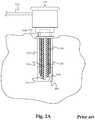
- FIG. 2Ashows a close up view of the blasting probe in accordance with some embodiments of the Present Application.
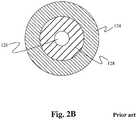
- FIG. 2Bshows an axial view of the blasting probe in accordance with some embodiments of the Present Application.
- FIG. 3shows a close up view of the blasting probe comprising two dielectric separators for high energy blasting in accordance with some embodiments of the Present Application.
- FIG. 4shows a flow chart illustrating a method of using the plasma blasting system to break or fracture a solid in accordance with some embodiments of the Present Application.
- FIG. 5shows a drawing of the improved probe from the top to the blast tip.
- FIG. 6shows a detailed view into the improved blast tip.
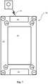
- FIG. 7shows a platform for mapping underground utilities.
- FIG. 8shows the platform with the plasma blast probe rail.
- FIG. 9shows the grid of receiving sensors on the platform.
- FIG. 10shows plasma blast probe for creating the shock waves.
- FIG. 1illustrates a plasma blasting system 100 for fracturing a solid 102 in accordance with some embodiments where electrical energy is deposited at a high rate (e.g. a few microseconds), into a blasting media 104 (e.g. water), wherein this fast discharge in the blasting media 104 creates plasma confined in a borehole 122 within the solid 102 .
- a pressure wave created by the discharge plasmaemanates from the blast region thereby fracturing the solid 102 .
- This plasma blasting system 100can also be used to create a shock wave in the ground (or in a solid) to allow the mapping of the ground by sensing the reflections of the shock wave and interpreting the structure of the ground.
- the plasma blasting system 100comprises a power supply 106 , an electrical storage unit 108 , a voltage protection device 110 , a high voltage switch 112 , a transmission line 114 , an inductor cable 116 , a blasting probe 118 and a blasting media 104 .
- the plasma blasting system 100comprises any number of blasting probes and corresponding blasting media.
- the power supply 106comprises any electrical power supply capable of supplying a sufficient voltage to the electrical storage unit 108 .
- the electrical storage unit 108comprises a capacitor bank or any other suitable electrical storage means.
- the voltage protection device 110comprises a crowbar circuit, with voltage-reversal protection means as is well known in the art.
- the high voltage switch 112comprises a spark gap, an ignitron, a solid state switch, or any other switch capable of handling high voltages and high currents.
- the transmission line 114comprises a coaxial cable.
- the transmission line 114comprises any transmission cable capable of adequately transmitting the pulsed electrical power.
- the power supply 106couples to the voltage protection device 110 and the electrical storage unit 108 via the transmission line 114 such that the power supply 106 is able to supply power to the electrical storage unit 108 through the transmission line 114 and the voltage protection device 110 is able to prevent voltage reversal from harming the system.
- the power supply 106 , voltage protection device 110 and electric storage unit 108also couple to the high voltage switch 112 via the transmission line 114 such that the switch 112 is able to receive a specified voltage/current from the electric storage unit 108 .
- the switch 112then couples to the cable 116 which couples to the blasting probe 118 again via the transmission line 114 such that the switch 112 is able to selectively allow the specified voltage/amperage received from the electric storage unit 108 to be transmitted through the cable 116 to the blasting probe 118 .
- FIG. 2Ashows one embodiment for a blasting probe.
- FIGS. 5 and 6show another embodiment.
- the blasting probe 118comprises an adjustment unit 120 , one or more ground electrodes 124 , one or more high voltage electrodes 126 and a dielectric separator 128 , wherein the end of the high voltage electrode 126 and the dielectric separator 128 constitute an adjustable blasting probe tip 130 .
- the adjustable blasting probe tip 130is reusable.
- the adjustable blasting probe tip 130comprises a material and is configured in a geometry such that the force from the blasts will not deform or otherwise harm the tip 130 .
- any number of dielectric separatorscomprising any number and amount of different dielectric materials are able to be utilized to separate the ground electrode 124 from the high voltage electrode 126 .
- the high voltage electrode 126is encircled by the hollow ground electrode 124 .
- the dielectric separator 128also encircles the high voltage electrode 126 and is used as a buffer between the hollow ground electrode 124 and the high voltage electrode 126 such that the three 124 , 126 , 128 share an axis and there is no empty space between the high voltage and ground electrodes 124 , 126 .
- any other configuration of one or more ground electrodes 124 , high voltage electrodes 126 and dielectric separators 128are able to be used wherein the dielectric separator 128 is positioned between the one or more ground electrodes 124 and the high voltage electrode 126 .
- the configuration shown in FIG. 2Bcould be switched such that the ground electrode was encircled by the high voltage electrode with the dielectric separator again sandwiched in between, wherein the end of the ground electrode and the dielectric separator would then comprise the adjustable probe tip.
- the adjustment unit 120comprises any suitable probe tip adjustment means as are well known in the art. Further, the adjustment unit 120 couples to the adjustable tip 130 such that the adjustment unit 120 is able to selectively adjust/move the adjustable tip 130 axially away from or towards the end of the ground electrode 124 , thereby adjusting the electrode gap 132 . In some embodiments, the adjustment unit 120 adjusts/moves the adjustable tip 130 automatically.
- the term “electrode gap”is defined as the distance between the high voltage and ground electrode 126 , 124 through the blasting media 104 . Thus, by moving the adjustable tip 130 axially in or out in relation to the end of the ground electrode 124 , the adjustment unit 120 is able to adjust the power of the blasting probe 118 .
- a change in the distance separating the electrodes 124 , 126 in the blasting probe 118is able to be used to vary the electrical power deposited into the solid 102 to be broken or fractured. Accordingly, by allowing more refined control over the electrode gap 132 via the adjustable tip 130 , better control over the blasting and breakage yield is able to be obtained.
- FIG. 3Another embodiment, as shown in FIG. 3 , is substantially similar to the embodiment shown in FIG. 2A except for the differences described herein.
- the blasting probe 118comprises an adjustment unit (not shown), a ground electrode 324 , a high voltage electrode 326 , and two different types of dielectric separators, a first dielectric separator 328 A and a second dielectric separator 328 B.
- the adjustable blasting probe tip 330comprises the end portion of the high voltage electrode 326 and the second dielectric separator 328 B.
- the adjustment unit(not shown) is coupled to the high voltage electrode 326 and the second dielectric separator 328 B (via the first dielectric separator 328 A), and adjusts/moves the adjustable probe tip 330 axially away from or towards the end of the ground electrode 324 , thereby adjusting the electrode gap 332 .
- the second dielectric separator 328 Bis a tougher material than the first dielectric separator 328 A such that the second dielectric separator 328 B better resists structural deformation and is therefore able to better support the adjustable probe tip 330 . Similar to the embodiment in FIG.
- the first dielectric 328 Ais encircled by the ground electrode 324 and encircles the high voltage electrode 326 such that all three share a common axis.
- the first dielectric separator 328 Ais supplanted by a wider second dielectric separator 328 B which surrounds the high voltage electrode 326 and forms a conic or parabolic support configuration as illustrated in the FIG. 3 .
- the conic or parabolic support configurationis designed to add further support to the adjustable probe tip 330 .
- any other support configurationcould be used to support the adjustable probe tip.
- the adjustable probe tip 330is configured to be resistant to deformation.
- the second dielectric separatorcomprises a polycarbonate tip.
- any other dielectric materialis able to be used.
- only one dielectric separatoris able to be used wherein the single dielectric separator both surrounds the high voltage electrode throughout the blast probe and forms the conic or parabolic support configuration around the adjustable probe tip.
- the embodiment shown in FIG. 3is well suited for higher power blasting, wherein the adjustable blast tip tends to bend and ultimately break.
- the adjustable probe tip 330is able to be reinforced with the second dielectric material 328 B in that the second dielectric material 328 B is positioned in a conic or parabolic geometry around the adjustable tip such that the adjustable probe tip 330 is protected from bending due to the blast.
- wateris used as the blasting media 104 .
- the watercould be poured down the borehole 122 before or after the probe 118 is inserted in the borehole 122 .
- the blasting media 104could be contained in a balloon or could be forced under pressure into the borehole 122 with the probe 118 .
- the blasting media 104is positioned within the borehole 122 of the solid 102 , with the adjustable tip 130 and at least a portion of the ground electrode 124 suspended within the blasting media 104 within the solid 102 .
- the blasting media 104is also in contact with the inner wall of the borehole 122 of the solid 102 .
- the amount of blasting media 104 to be usedis dependent on the size of the solid and the size of the blast desired and its calculation is well known in the art.
- the adjustable tip 130is axially extended or retracted by the adjustment unit 120 thereby adjusting the electrode gap 132 based on the size of the solid 102 to be broken and/or the blast energy desired at the step 402 .
- the blast probe 118is then inserted into the borehole 122 of the solid such that at least a portion of the ground and high voltage electrodes 124 , 126 of the plasma blasting probe 118 are submerged or put in contact with the blasting media 104 which is in direct contact with the solid 102 to be fractured or broken at the step 404 .
- the electrode cap 132is able to be adjusted after insertion of the blasting probe 118 into the borehole 122 .
- the electrical storage unit 108is then charged by the power supply 106 at a relatively low rate of speed (e.g., a few seconds) at the step 406 .
- the switch 112is then activated causing the energy stored in the electrical storage unit 108 to discharge at a very high rate of speed (e.g. tens of microseconds) forming a pulse of electrical energy (e.g.
- the blasting media 104is subjected to a sudden increase in temperature (e.g. about 5000 to 10,000° C. or more) due to a plasma channel formed between the electrodes 124 , 126 , which is confined in the borehole 122 and not able to dissipate.
- the heat generatedvaporizes or reacts with part a the blasting media 104 , creating a steep pressure rise confined in the borehole 122 .
- a blast wavecomprising a layer of compressed water (or other blasting media 104 ) is formed in front of the vapor containing most of the energy from the discharge.
- this blast wavethat then applies force to the inner walls of the borehole 122 and ultimately breaks or fractures the solid 102 .
- the pressure expressed by the wave front(which is able to reach up to 2.5 GPa and over), exceeds the tensile strength of the solid 102 , fracture is expected.
- the blasting abilitydepends on the tensile strength of the solid 102 where the plasma blasting probe 118 is placed, and on the intensity of the pressure formed.
- the major cause of the fracturing or breaking of the solid 102is the impact of this compressed water shock wave front which is comparable to one resulting from a high-energy chemical explosive (e.g., dynamite).
- the blast probe of the blasting system described hereinwas inserted into solids comprising either concrete or granite with cast or drilled boreholes having a one inch diameter.
- a capacitor bank systemwas used for the electrical storage unit and was charged at a low current and then discharged at a high current via the high voltage switch 112 . Peak power achieved was measured in the gigawatts. Pulse rise times were around 10-20 ⁇ sec and pulse lengths were on the order of 50-100 ⁇ sec. The system was able to produce pressures of up to 2.5 GPa and break concrete and granite blocks with masses of more than 850 kg with one discharge.
- FIG. 5shows an alternative probe 500 embodiment.
- Probe coupler 501electrically connects to cable 116 for receiving power from the capacitors 108 and mechanically connects to tethers (could be the cable 116 or other mechanical devices to prevent the probe 500 from departing the borehole 122 after the blast.
- the probe coupler 501may incorporate a high voltage coaxial BNC-type high voltage/high current connector to compensate lateral Lorentz' forces on the central electrode and to allow for easy connection of the probe 500 to the cable 116 .
- the mechanical connectionmay include an eye hook to allow carabiners or wire rope clip to connect to the probe 500 . Other mechanical connections could also be used.
- the probe connection 501could be made of plastic or metal.
- the probe connector 501could be circular in shape and 2 inches in diameter for applications where the probe is inserted in a borehole 122 that is the same depth as the probe 500 .
- the probe 500may be inserted in a deep hole, in which case the probe connector 501 must be smaller than the borehole 122 .
- the probe connector 501is mechanically connected to the shaft connector 502 with screws, welds, or other mechanical connections.
- the shaft connector 502is connected to the probe shaft 503 .
- the connection to the probe shaft 503could be through male threads on the top of the probe shaft 503 and female threads on the shaft connector 502 .
- the shaft connector 502could include a set screw on through the side to keep the shaft 503 connected to the shaft connector 502 .
- the shaft connector 502could be a donut shape and made of stainless steel, copper, aluminum, or another conductive material. Electrically, the shaft connector 502 is connected to the ground side of the cable 116 .
- An insulated wire from the probe connector 501 to the high voltage electrode 602passes through the center of the shaft connector 502 .
- the shaft connectorcould be about 1.75 inches in diameter.
- the shaft 503is a hollow shaft that may be threaded 507 at one (or both) ends.
- the shaft 503made of stainless steel, copper, aluminum, or another conductive material. Electrically, the shaft 503 is connected to the ground side of the cable 116 through the shaft connector 502 . An insulated wire from the probe connector 501 to the high voltage electrode 602 passes through the center of the shaft 503 .
- Mechanically, the shaft 503is connected to the shaft connector 502 as described above. At the other end, the shaft 503 is connected to the cage 506 through the threaded bolt 508 into the shafts threads 507 , or through another mechanical connection (welding, set screws, etc).
- the shaft 503may be circular and 1.5 inches in diameter in a 2 inch borehole 122 application.
- the shaftmay be 40 inches long, in one embodiment.
- blast force inhibitors 504 a , 504 b , 504 cmay be placed to inhibit the escape of blast wave and the blasting media 104 during the blast.
- the blast force inhibitors 504 a , 504 b , 504 cmay be made of the same material as the shaft 503 and may be welded to the shaft, machined into the shaft, slip fitted onto the shaft or connected with set screws.
- the inhibitors 504 a , 504 b , 504 ccould be shaped as a donut.
- the shaft 503connects to the cage 506 through a threaded bolt 508 that threads into the shaft's threads 507 . This allows adjustment of the positioning of the cage 506 and the blast. Other methods of connecting the cage 503 to the shaft 506 could be used without deviating from the invention (for example, a set screw or welding).
- the cage 506may be circular and may be 1.75 inches in diameter.
- the cage 506may be 4-6 inches long, and may include 4-8 holes 604 in the side to allow the blast to impact the side of the blast hole 122 . These holes 604 may be 2-4 inches high and may be 0.5-1 inch wide, with 0.2-0.4 inch pillars in the cage 506 attaching the bottom of the cage 506 to the top.
- the cage 506could be made of high strength steel, carbon steel, copper, titanium, tungsten, aluminum, cast iron, or similar materials of sufficient strength to withstand the blast. Electrically, the cage 506 is part of the ground circuit from the shaft 503 to the ground electrode 601 .
- a single blast cagecould be made of weaker materials, such as plastic, with a wire connected from the shaft to the ground electrode 601 at the bottom of the cage 506 .
- a ground electrode 601is located at the bottom of the cage 506 .
- the ground electrode 601is made of a conductive material such as steel, aluminum, copper or similar.
- the ground electrode 601could be a bolt screwed in female threads at the bottom of the cage 506 . Or a nut could be inserted into the bottom of the cage for threading the bolt 601 and securing it to the cage 506 .
- the bolt 601can be adjusted with washers or nuts on both sides of the cage 506 to allow regulate the gap between the ground electrode bolt 601 and the high voltage electrode 602 , depending upon the type of solid 102 .
- the wire that runs down the shaft 503is electrically connected to the high voltage electrode 602 .
- a dielectric separator 603keeps the electricity from coming in contact with the cage 506 . Instead, when the power is applied, a spark is formed between the high voltage electrode 602 and the ground electrode 601 .
- the distance between the high voltage electrode 602 and the ground electrode 601must be less than the distance from the high voltage electrode 602 and the cage 506 walls.
- the two electrodes 601 , 602are on the same axis with the tips opposing each other.
- the cage 506 wallswill be about 0.8 inches from the high voltage electrode 602 , so the distance between the high voltage electrode 602 and the ground electrode 601 should be less than 0.7 inches.
- an insulatorcould be added inside the cage to prevent sparks between the electrode 602 and the cage when the distance between the high voltage electrode 602 and the ground electrode 601 is larger.
- This cage 506 designcreates a mostly cylindrical shock wave with the force applied to the sides of the borehole 122 .
- additional metal or plastic cone-shaped elementsmay be inserted around lower 601 and upper electrodes 602 to direct a shock wave outside the probe and to reduce axial forces inside the cage.
- a balloon filled with watercould be inserted in the cage 506 or the cage 506 could be enclosed in a water filled balloon to keep the water around the electrodes 601 , 602 in a horizontal or upside down application.
- the method of and apparatus for plasma blasting described hereinhas numerous advantages. Specifically, by adjusting the blasting probe's tip and thereby the electrode gap, the plasma blasting system is able to provide better con troll over the power deposited into the specimen to be broken. Consequently, the power used is able to be adjusted according to the size and tensile strength of the solid to be broken instead of using the same amount of power regardless of the solid to be broken. Furthermore, the system efficiency is also increased by using a thixotropic or reactive materials (RIM) blasting media in the plasma blasting system.
- RIMreactive materials
- the thixotropic or RM properties of the blasting mediamaximize the amount of force applied to the solid relative to the energy input into the system by not allowing the energy to easily escape the borehole as described above and to add energy from the RM reaction.
- the thixotropic or RIM blasting mediais inert, it is safer than the use of combustible chemicals and/or explosives. As a result, the plasma blasting system is more efficient in terms of energy, safer in terms of its inert qualities, and requires smaller components thereby dramatically decreasing the cost of operation.
- the above probes in FIG. 2, 3 and in FIG. 5, 6can be used to create shock waves in the ground to map soil structures, such as is done in oil and gas exploration.
- a borehole 122is drilled in the ground 102 .
- Blasting probe 118 or probe 500is inserted into the borehole 122 .
- directional probe 1000could be used in some applications.
- the energy from the energy storage unit 108 to create the plasma blastis adjusted prevent the blast from breaking the surrounding soil, but providing enough energy that the blast creates shock waves in the ground 102 .
- the plasma blastscould also be done in water in an alternative embodiment, such as for deep water oil and gas exploration.
- the shock wavestravel from the probe 118 , 500 , 1000 through the ground 102 (or water) where the shock waves are reflected off of the various structures in the ground 102 (or water). These reflections are then detected by sensors places on or in the ground (or water). These sensors could be acoustic sensors or seismic sensors (geophones or hydrophones) in known locations relative to the position of the source. The recorded signals are then subjected to specialist processing and interpretation to yield comprehensible information about the subsurface.
- Plasma blastingcan also be done above ground, sending the shock waves onto the surface of the ground.
- precise mapping of the location of wires, pipes, conduit, etc.is important to efficiently and safely access a wire or pipe.
- Traditional methodscan require excessive excavation to locate the desired wire or pipe, with great care taken not to impact other utilities.
- the platform 700could be driven on and off of a truck or trailer.
- the platform 700could include a power source 704 such as a battery, plugged into an AC power outlet, or could be powered by a gasoline or diesel autonomous motor-generator or any other power source.
- the power source 704could also include capacitors 110 or other source of power for the plasma blast.
- the platform 700could be mounted on four wheels 705 a , 705 b , 705 c , 705 d for moving the platform 700 in any direction with precision.
- the wheels 705 a , 705 b , 705 c , 705 dcould be omni-wheels or Mecanum wheels.
- One or more of the wheels 705 a , 705 b , 705 c , 705 dcould be powered by individual motors or by a mechanical connection to a motor. Wheels 705 a , 705 b , 705 c , 705 d are mounted below the platform, and contact with the ground 102 . Wheels 705 a , 705 b , 705 c , 705 d could be could also include a suspension system to keep the platform 700 relatively level as it traverses the ground 102 .
- the platform 700could be a steel or aluminum frame, welded in a rectangle with a decking 707 material for holding various components 702 , 704 , 706 a , 706 b , 706 c , 706 d .
- the decking 707 materialcould be sheet metal, aluminum, plastic, wood, or similar materials.
- a rectangular frame 703for the transmitters (plasma blast probes) and receivers (sensors).
- GPS receivers 706 a , 706 b , 706 c , 706 dare secured in precise locations on the decking 707 to determine exactly where the platform 707 is located and how the platform is oriented.
- the GPS receivers 706 a , 706 b , 706 c , 706 dcould be replaced or supplemented with other location technologies, such as IPS, cell tower triangulation, or beacon technology.
- a special purpose controller 702is also located on the decking 707 .
- the special purpose controller 702is shielded to protect the controller from electrical, magnetic, and mechanical interference from the plasma blasts.
- the controller 702could include a special purpose microprocessor, memory, a mass storage device (hard disk, CD or solid state drive), IO interfaces to the probes 118 , 500 , 1000 and the sensors, power conditioning equipment, a Bluetooth interface, a network interfaces (could be WiFi, Cellular, wired Ethernet, or similar).
- the controller 702could be connected to a 3-D joystick 701 for controlling the movement of the platform 700 .
- the connection 708 between the controller 702 and the joystick 701could be Bluetooth, Wi-Fi, cellular, or hardwired.
- the joystick 701could be used to drive the platform 700 off of the truck or trailer, to assist with positioning (although positioning could also be done automatically based on specific GPS coordinates), or to move the platform to s specific location.
- the joystick 701could be replaced with a laptop, a server, a smartphone, or similar device using other user interface technologies (dual joysticks, touchscreens, keyboard input, voice commands, and similar devices).
- the network interfacecould be used to transmit and receive data from remote servers that process or record the received from the sensors.
- the processing of the data from the sensorscould be handled locally on the microprocessor or remotely on a server.
- the platform 700also includes a drill for making boreholes and a rock breaking plasma blasting probe 118 , 500 . This allows the platform 700 to both map the underground structures and to then to use that map to break up the underground structure with precision to access pipes or wires with the minimum of excavation. In some embodiments, once the structure is mapped, a large, course plasma blast is used to get to the correct area, and then more precise plasma blasts are used to delicately break the material around the pipe.
- the controller 702could operate algorithms to control the separation of the electrodes in the probe 118 , 500 , 1000 and the amount of energy (varying voltages and/or the number of capacitors) sent to the probe to create the spark/plasma blast. In addition, the controller 702 could control length of time that the spark is present and the timing of one or more plasma blasts if multiple blasts are desired. By controlling these factors the characteristics of the plasma blast can be controlled with precision. Other algorithms could take soil conditions into account for the determination of the blast characteristics to use.
- the frame 703contains a rack 801 of plasma blasting probes 802 a - l .
- the probes 802 - lcould be one probe with a number of different positions along the rack 801 (moved manually or with a stepper motor), or it could be a number of different probes mounted on the rack 801 .
- Rack 801moves along the frame 703 by means of a stepper motor or similar method for movement (including manual movement by an operator).
- the probes 802 a - lare fired sequentially, and the sensors record the shock wave reflections in the controller 702 .
- each probe 802 a - lis moved down to make contact with the ground 102 .
- the rack 801moves to another position on the frame 703 , and the process in repeated.
- the controller 702 or the serverprocesses the recorded reflection data and produces a map of the structure of the ground below the platform 700 . Note that any number of probe 802 a - l locations can be used and any number of positions of the rack 801 on the frame 703 without deviating from this aspect of the invention.
- the probes 802 a - lcould be arranged in a grid on the frame 703 , such that the only movement is to make the probe contact the ground 102 before firing, Each probe 802 a - l is electrically connect to the IO interface of the controller 702 , and the controller controls the time and energy used for the plasma blast.
- FIG. 9shows the frame 703 with a grid of sensors 901 for detecting the shock waves after the plasma blast. Any number of sensors can be on the grid 901 , each configured to sense the reflections of the shock wave on the ground 102 . Each sensor is electrically connected to the IO interface of the controller 702 for sending the reflected shock waves to the controller 702 for storage. The controller 702 stores the sensor location, the precise time, and the amplitude of the detected shock wave as well as the precise location and time of the plasma blast.
- the plasma blast probes and the sensorscould be replaced with other devices to create test waves and to detect reflected waves, such as ultrasound devices, and/or radar devices.
- FIG. 10is a diagram of a directional probe 1000 such as could be used on the platform 700 as probes 802 a - l .
- the directional probe 1000could be a cylinder with a flat top and bottom.
- the directional probe 1000could be made of rugged material such as steel, iron, or similar.
- the top of the probe 1000is attached but not sealed, so that shock waves and air can escape if necessary during a plasma blast.
- the probe 1000is filled with blasting media 104 such as water.
- a parabolic mirror 1001Inside the probe 1000 is a parabolic mirror 1001 that is made of steel or other rugged material.
- the parabolic mirror 1001is attached to the walls of the probe 1000 .
- the bottom of the probe 1000is completely attached, perhaps welded, to the walls of the probe 1000 .
- a layer of rubber 1003(or similar material) is placed on the bottom of the probe 1000 .
- the probe 1000In the center of the bottom the probe 1000 is a hole (both in the rubber 1003 and in the bottom of the probe 1000 ) with a mechanical steel (or similar material) slug 1005 .
- the parabolic mirror 1001is aimed so that the shock waves 1007 a , 1007 b from a plasma blast 1006 are focused on the slug 1005 . This causes the focused energy on the slug 1005 to be transferred to the pavement or a road surface 1004 (or similar solid surface), causing shock waves 1008 to be transferred to the ground 102 . If there is no pavement nor road surface, a steel plate (or similar) could be placed on the ground, and the shock waves directed through the steel plate.
- the plasma blast 1006is caused by a spark between a plurality of electrodes positioned within the directional probe 1000 .
- a description of the electrode functionality and connectionscan be found elsewhere in this document.
- the shock wave 1008travels through the ground 102 until it hits an underground structure. Upon hitting the underground structure, reflections from the structure return to the surface of the ground, and are picked up by the array of sensors 901 .
Landscapes
- Engineering & Computer Science (AREA)
- Physics & Mathematics (AREA)
- General Engineering & Computer Science (AREA)
- Life Sciences & Earth Sciences (AREA)
- Plasma & Fusion (AREA)
- General Life Sciences & Earth Sciences (AREA)
- Spectroscopy & Molecular Physics (AREA)
- Remote Sensing (AREA)
- Geology (AREA)
- Environmental & Geological Engineering (AREA)
- Mining & Mineral Resources (AREA)
- Acoustics & Sound (AREA)
- General Physics & Mathematics (AREA)
- Geophysics (AREA)
- Fluid Mechanics (AREA)
- Geochemistry & Mineralogy (AREA)
- Geophysics And Detection Of Objects (AREA)
Abstract
Description
Claims (20)
Priority Applications (1)
| Application Number | Priority Date | Filing Date | Title |
|---|---|---|---|
| US16/285,120US10844702B2 (en) | 2018-03-20 | 2019-02-25 | Precision utility mapping and excavating using plasma blasting |
Applications Claiming Priority (2)
| Application Number | Priority Date | Filing Date | Title |
|---|---|---|---|
| US201862645247P | 2018-03-20 | 2018-03-20 | |
| US16/285,120US10844702B2 (en) | 2018-03-20 | 2019-02-25 | Precision utility mapping and excavating using plasma blasting |
Publications (2)
| Publication Number | Publication Date |
|---|---|
| US20190186249A1 US20190186249A1 (en) | 2019-06-20 |
| US10844702B2true US10844702B2 (en) | 2020-11-24 |
Family
ID=66815763
Family Applications (1)
| Application Number | Title | Priority Date | Filing Date |
|---|---|---|---|
| US16/285,120Active2039-06-15US10844702B2 (en) | 2018-03-20 | 2019-02-25 | Precision utility mapping and excavating using plasma blasting |
Country Status (1)
| Country | Link |
|---|---|
| US (1) | US10844702B2 (en) |
Families Citing this family (5)
| Publication number | Priority date | Publication date | Assignee | Title |
|---|---|---|---|---|
| US11268796B2 (en)* | 2018-02-20 | 2022-03-08 | Petram Technologies, Inc | Apparatus for plasma blasting |
| US10866076B2 (en)* | 2018-02-20 | 2020-12-15 | Petram Technologies, Inc. | Apparatus for plasma blasting |
| US12312956B2 (en) | 2020-09-03 | 2025-05-27 | Petram Technologies, Inc. | Robust plasma blast probe tip |
| CN116710728A (en) | 2020-11-10 | 2023-09-05 | 戴诺诺贝尔亚太股份有限公司 | Systems and methods for determining water depth and explosive depth in blastholes |
| WO2023057791A1 (en)* | 2021-10-06 | 2023-04-13 | Sadra Atiyeh Mahour | A hydraulic plasma stone blaster probe |
Citations (79)
| Publication number | Priority date | Publication date | Assignee | Title |
|---|---|---|---|---|
| US3324665A (en)* | 1964-10-28 | 1967-06-13 | Shell Oil Co | Method of stabilizing piles |
| US3553969A (en)* | 1968-12-23 | 1971-01-12 | Chicago Bridge & Iron Co | Submerged oil storage structure |
| US3628146A (en)* | 1970-05-22 | 1971-12-14 | Zenith Radio Corp | Touch-actuated mode control circuit |
| US3679007A (en)* | 1970-05-25 | 1972-07-25 | Louis Richard O Hare | Shock plasma earth drill |
| US3763610A (en)* | 1971-05-20 | 1973-10-09 | J Ballew | Earth anchor and apparatus for applying |
| US3896917A (en)* | 1972-06-23 | 1975-07-29 | Taplin Business Machines | Binary bar code printing device and binary bar code printed matter |
| US4074758A (en)* | 1974-09-03 | 1978-02-21 | Oil Recovery Corporation | Extraction method and apparatus |
| US4169503A (en)* | 1974-09-03 | 1979-10-02 | Oil Recovery Corporation | Apparatus for generating a shock wave in a well hole |
| US4222684A (en)* | 1977-10-26 | 1980-09-16 | Winfried Rosenstock | Method of driving sheet piles into a rock substratum |
| US4268192A (en)* | 1978-09-11 | 1981-05-19 | Raymond International Builders, Inc. | Concrete wall construction |
| US4345650A (en)* | 1980-04-11 | 1982-08-24 | Wesley Richard H | Process and apparatus for electrohydraulic recovery of crude oil |
| US4465401A (en)* | 1981-06-15 | 1984-08-14 | In Situ Technology, Inc. | Minimizing subsidence effects during production of coal in situ |
| US4479680A (en)* | 1980-04-11 | 1984-10-30 | Wesley Richard H | Method and apparatus for electrohydraulic fracturing of rock and the like |
| US4653697A (en)* | 1985-05-03 | 1987-03-31 | Ceee Corporation | Method and apparatus for fragmenting a substance by the discharge of pulsed electrical energy |
| US4741405A (en)* | 1987-01-06 | 1988-05-03 | Tetra Corporation | Focused shock spark discharge drill using multiple electrodes |
| US4806153A (en)* | 1981-01-22 | 1989-02-21 | Kisojiban Consultants Co., Ltd. | Method and apparatus for investigating subsurface conditions |
| US4997044A (en) | 1989-12-01 | 1991-03-05 | Stack Walter E | Apparatus for generating hydraulic shock waves in a well |
| US5004050A (en)* | 1988-05-20 | 1991-04-02 | Sizonenko Olga N | Method for well stimulation in the process of oil production and device for carrying same into effect |
| US5106164A (en)* | 1990-04-20 | 1992-04-21 | Noranda Inc. | Plasma blasting method |
| US5301169A (en)* | 1989-05-08 | 1994-04-05 | Secretary Of State For Trade And Industry In Her Britannic Majesty's Government Of The United Kingdom Of Great Britain And Northern Ireland | Seismic source |
| US5388521A (en)* | 1993-10-18 | 1995-02-14 | Coursen Family Trust | Method of reducing ground vibration from delay blasting |
| US5397961A (en)* | 1993-12-20 | 1995-03-14 | Ayers; Richard A. | Apparatus for generating a pulsed plasma in a liquid medium |
| US5416391A (en)* | 1992-07-31 | 1995-05-16 | Correa; Paulo N. | Electromechanical transduction of plasma pulses |
| US5425570A (en)* | 1994-01-21 | 1995-06-20 | Maxwell Laboratories, Inc. | Method and apparatus for plasma blasting |
| US5482357A (en)* | 1995-02-28 | 1996-01-09 | Noranda, Inc. | Plasma blasting probe assembly |
| US5573307A (en)* | 1994-01-21 | 1996-11-12 | Maxwell Laboratories, Inc. | Method and apparatus for blasting hard rock |
| US5773750A (en)* | 1995-10-30 | 1998-06-30 | Soosan Special Purpose Vehicle Co., Ltd. | Rock fragmentation system using gold schmidt method |
| US5980446A (en)* | 1997-08-12 | 1999-11-09 | Lockheed Martin Idaho Technologies Company | Methods and system for subsurface stabilization using jet grouting |
| US6012874A (en)* | 1997-03-14 | 2000-01-11 | Dbm Contractors, Inc. | Micropile casing and method |
| RU2144980C1 (en) | 1998-03-23 | 2000-01-27 | Общество с ограниченной ответственностью "Инженерно-производственный центр" | Method of treatment of bottom-hole formation zone of wells producing heavy oils and native bitumens |
| US6227293B1 (en)* | 2000-02-09 | 2001-05-08 | Conoco Inc. | Process and apparatus for coupled electromagnetic and acoustic stimulation of crude oil reservoirs using pulsed power electrohydraulic and electromagnetic discharge |
| US20010011590A1 (en)* | 2000-02-09 | 2001-08-09 | Thomas Sally A. | Process and apparatus for coupled electromagnetic and acoustic stimulation of crude oil reservoirs using pulsed power electrohydraulic and electromagnetic discharge |
| US6283555B1 (en)* | 1995-07-24 | 2001-09-04 | Hitachi Zosen Corporation | Plasma blasting with coaxial electrodes |
| RU2184221C1 (en) | 2001-07-16 | 2002-06-27 | Пазин Александр Николаевич | Method of complex action on face zone of well |
| US6457778B1 (en)* | 1999-03-02 | 2002-10-01 | Korea Accelerator And Plasma Research Association | Electro-power impact cell for plasma blasting |
| US6490527B1 (en)* | 1999-07-13 | 2002-12-03 | The United States Of America As Represented By The Department Of Health And Human Services | Method for characterization of rock strata in drilling operations |
| RU2194846C2 (en) | 2001-02-01 | 2002-12-20 | Открытое акционерное общество "Всероссийский нефтегазовый научно-исследовательский институт им. акад. А.П.Крылова" | Method of paraffin deposit prevention in oil well |
| US6499536B1 (en)* | 1997-12-22 | 2002-12-31 | Eureka Oil Asa | Method to increase the oil production from an oil reservoir |
| RU2199659C1 (en) | 2001-10-01 | 2003-02-27 | Ойл Технолоджи (Оверсиз) Продакшн Лтд. | Technique intensifying oil output |
| US6597632B2 (en)* | 2001-03-01 | 2003-07-22 | Nonlinear Seismic Imaging, Inc. | Mapping subsurface fractures using nonlinearity measurements |
| RU2213860C2 (en) | 2001-10-22 | 2003-10-10 | Закрытое акционерное общество Акционерная компания "Ионно-плазменные технологии" | Method of pulse and ion-plasma stimulation of oil formation |
| US6761416B2 (en)* | 2002-01-03 | 2004-07-13 | Placer Dome Technical Services Limited | Method and apparatus for a plasma-hydraulic continuous excavation system |
| US6772105B1 (en)* | 1999-09-08 | 2004-08-03 | Live Oak Ministries | Blasting method |
| US6935702B2 (en)* | 2001-04-06 | 2005-08-30 | Kumagai Gumi Co., Ltd. | Crushing apparatus electrode and crushing apparatus |
| RU2261986C1 (en) | 2004-11-22 | 2005-10-10 | Закрытое акционерное общество "Алойл" | Method for complex well bottom zone treatment |
| US20060038437A1 (en)* | 2004-08-20 | 2006-02-23 | Tetra Corporation | Electrohydraulic boulder breaker |
| RU2272128C1 (en) | 2004-07-21 | 2006-03-20 | Общество с ограниченной ответственностью "Корпорация Уралтехнострой" (ООО "Корпорация Уралтехнострой"-Российская Федерация) | Formation fluid treatment method |
| RU2282021C2 (en) | 2004-06-04 | 2006-08-20 | Ильгиз Фатыхович Садыков | Method for well bottom zone treatment |
| RU2283950C2 (en) | 2004-03-25 | 2006-09-20 | Открытое акционерное общество "Шешмаойл" | Treatment method for well bottomhole productive formation zone characterized by difficult-to-recover oil |
| RU2295031C2 (en) | 2005-02-10 | 2007-03-10 | Алемасов Вячеслав Евгеньевич | Method for performing electro-hydro-impulse processing in oil-gas wells and device for realization of said method |
| RU2298641C2 (en) | 2005-07-29 | 2007-05-10 | Александр Александрович Иванов | Method for oil-producing well cleaning |
| RU2298642C1 (en) | 2005-09-14 | 2007-05-10 | Николай Александрович Петров | Method for asphalt-tar-paraffin deposits prevention in oil production equipment |
| US20070292215A1 (en)* | 2006-06-14 | 2007-12-20 | Chang Sun Kim | Method of constructing underground pile having expanded bulb and underground pile having expanded bulb constructed by the method |
| RU2314412C1 (en) | 2006-06-26 | 2008-01-10 | Общество с ограниченной ответственностью "Клариант (РУС)" | Method and device for oil well treatment |
| RU2317409C1 (en) | 2006-04-26 | 2008-02-20 | ООО "Научно-производственное объединение "Волгахимэкспорт" | Method and device for well bottom zone and productive reservoir treatment |
| RU2327027C2 (en) | 2006-04-20 | 2008-06-20 | Александр Владимирович Шипулин | Processing method of bottomhole zone |
| RU2007101698A (en) | 2007-01-18 | 2008-07-27 | Александр Дмитриевич Рыбаков (RU) | METHOD FOR INCREASING OIL RECOVERY |
| RU2335658C2 (en) | 2006-10-31 | 2008-10-10 | Федеральное государственное образовательное учреждение высшего профессионального образования Горский государственный аграрный университет | Electrohydraulic method of oil production and method to this effect |
| US7562740B2 (en)* | 2003-10-28 | 2009-07-21 | Schlumberger Technology Corporation | Borehole acoustic source |
| US20100270038A1 (en)* | 2006-02-16 | 2010-10-28 | Chevron U.S.A. Inc. | Kerogen Extraction from Subterranean Oil Shale Resources |
| US7849919B2 (en)* | 2007-06-22 | 2010-12-14 | Lockheed Martin Corporation | Methods and systems for generating and using plasma conduits |
| US20110139441A1 (en)* | 2009-12-11 | 2011-06-16 | Technological Research Ltd. | System, apparatus and method for stimulating wells and managing a natural resource reservoir |
| US20110227395A1 (en)* | 2010-03-17 | 2011-09-22 | Auburn University | Method of and apparatus for plasma blasting |
| US20120043075A1 (en)* | 2009-04-28 | 2012-02-23 | Obschestvo S Ogranichennoi Otvetstvennostju "Sonovita" | Method and assembly for recovering oil using elastic vibration energy |
| US8616302B2 (en)* | 2004-08-20 | 2013-12-31 | Sdg, Llc | Pulsed electric rock drilling apparatus with non-rotating bit and directional control |
| US20140027110A1 (en)* | 2012-07-27 | 2014-01-30 | Novas Energy Group Limited | Plasma source for generating nonlinear, wide-band, periodic, directed, elastic oscillations and a system and method for stimulating wells, deposits and boreholes using the plasma source |
| RU2520672C2 (en) | 2012-09-28 | 2014-06-27 | Открытое акционерное общество "Татнефть" им. В.Д. Шашина | Production simulation method in oil wells and device for its implementation |
| US8789772B2 (en)* | 2004-08-20 | 2014-07-29 | Sdg, Llc | Virtual electrode mineral particle disintegrator |
| US20140251599A1 (en)* | 2012-07-17 | 2014-09-11 | Alexander Petrovich Linetskiy | Method For Developing Deposits And Extracting Oil And Gas From Shale Formations |
| US20160168815A1 (en)* | 2014-12-15 | 2016-06-16 | Hubbell Incorporated | Guy wire anchoring systems, brackets and kits |
| US20170002535A1 (en)* | 2014-04-07 | 2017-01-05 | Halliburton Energy Services, Inc. | Soil and Rock Grouting Using a Hydrajetting Tool |
| US9719302B2 (en)* | 2008-08-20 | 2017-08-01 | Foro Energy, Inc. | High power laser perforating and laser fracturing tools and methods of use |
| US9739574B1 (en)* | 2016-02-24 | 2017-08-22 | Vln Advanced Technologies Inc. | Electro-discharge system for neutralizing landmines |
| US9770724B2 (en)* | 2015-01-21 | 2017-09-26 | Vln Advanced Technologies Inc. | Electrodischarge apparatus |
| US9816356B2 (en)* | 2015-03-27 | 2017-11-14 | Georezonans Ltd. | Method for extracting methane from coal beds and from penetrating rock enclosing a coal bed |
| US9896917B2 (en)* | 2013-08-02 | 2018-02-20 | Olga Nikolaevna Sizonenko | Oil production intensification device and method |
| US10060195B2 (en)* | 2006-06-29 | 2018-08-28 | Sdg Llc | Repetitive pulsed electric discharge apparatuses and methods of use |
| US10254499B1 (en)* | 2016-08-05 | 2019-04-09 | Southern Methodist University | Additive manufacturing of active devices using dielectric, conductive and magnetic materials |
| US10407995B2 (en)* | 2012-07-05 | 2019-09-10 | Sdg Llc | Repetitive pulsed electric discharge drills including downhole formation evaluation |
- 2019
- 2019-02-25USUS16/285,120patent/US10844702B2/enactiveActive
Patent Citations (82)
| Publication number | Priority date | Publication date | Assignee | Title |
|---|---|---|---|---|
| US3324665A (en)* | 1964-10-28 | 1967-06-13 | Shell Oil Co | Method of stabilizing piles |
| US3553969A (en)* | 1968-12-23 | 1971-01-12 | Chicago Bridge & Iron Co | Submerged oil storage structure |
| US3628146A (en)* | 1970-05-22 | 1971-12-14 | Zenith Radio Corp | Touch-actuated mode control circuit |
| US3679007A (en)* | 1970-05-25 | 1972-07-25 | Louis Richard O Hare | Shock plasma earth drill |
| US3763610A (en)* | 1971-05-20 | 1973-10-09 | J Ballew | Earth anchor and apparatus for applying |
| US3896917A (en)* | 1972-06-23 | 1975-07-29 | Taplin Business Machines | Binary bar code printing device and binary bar code printed matter |
| US4074758A (en)* | 1974-09-03 | 1978-02-21 | Oil Recovery Corporation | Extraction method and apparatus |
| US4169503A (en)* | 1974-09-03 | 1979-10-02 | Oil Recovery Corporation | Apparatus for generating a shock wave in a well hole |
| US4222684A (en)* | 1977-10-26 | 1980-09-16 | Winfried Rosenstock | Method of driving sheet piles into a rock substratum |
| US4268192A (en)* | 1978-09-11 | 1981-05-19 | Raymond International Builders, Inc. | Concrete wall construction |
| US4345650A (en)* | 1980-04-11 | 1982-08-24 | Wesley Richard H | Process and apparatus for electrohydraulic recovery of crude oil |
| US4479680A (en)* | 1980-04-11 | 1984-10-30 | Wesley Richard H | Method and apparatus for electrohydraulic fracturing of rock and the like |
| US4806153A (en)* | 1981-01-22 | 1989-02-21 | Kisojiban Consultants Co., Ltd. | Method and apparatus for investigating subsurface conditions |
| US4465401A (en)* | 1981-06-15 | 1984-08-14 | In Situ Technology, Inc. | Minimizing subsidence effects during production of coal in situ |
| US4653697A (en)* | 1985-05-03 | 1987-03-31 | Ceee Corporation | Method and apparatus for fragmenting a substance by the discharge of pulsed electrical energy |
| US4741405A (en)* | 1987-01-06 | 1988-05-03 | Tetra Corporation | Focused shock spark discharge drill using multiple electrodes |
| US5004050A (en)* | 1988-05-20 | 1991-04-02 | Sizonenko Olga N | Method for well stimulation in the process of oil production and device for carrying same into effect |
| US5301169A (en)* | 1989-05-08 | 1994-04-05 | Secretary Of State For Trade And Industry In Her Britannic Majesty's Government Of The United Kingdom Of Great Britain And Northern Ireland | Seismic source |
| US4997044A (en) | 1989-12-01 | 1991-03-05 | Stack Walter E | Apparatus for generating hydraulic shock waves in a well |
| US5106164A (en)* | 1990-04-20 | 1992-04-21 | Noranda Inc. | Plasma blasting method |
| US5416391A (en)* | 1992-07-31 | 1995-05-16 | Correa; Paulo N. | Electromechanical transduction of plasma pulses |
| US5388521A (en)* | 1993-10-18 | 1995-02-14 | Coursen Family Trust | Method of reducing ground vibration from delay blasting |
| US5397961A (en)* | 1993-12-20 | 1995-03-14 | Ayers; Richard A. | Apparatus for generating a pulsed plasma in a liquid medium |
| US5425570A (en)* | 1994-01-21 | 1995-06-20 | Maxwell Laboratories, Inc. | Method and apparatus for plasma blasting |
| US5573307A (en)* | 1994-01-21 | 1996-11-12 | Maxwell Laboratories, Inc. | Method and apparatus for blasting hard rock |
| US5482357A (en)* | 1995-02-28 | 1996-01-09 | Noranda, Inc. | Plasma blasting probe assembly |
| US6283555B1 (en)* | 1995-07-24 | 2001-09-04 | Hitachi Zosen Corporation | Plasma blasting with coaxial electrodes |
| US5773750A (en)* | 1995-10-30 | 1998-06-30 | Soosan Special Purpose Vehicle Co., Ltd. | Rock fragmentation system using gold schmidt method |
| US6012874A (en)* | 1997-03-14 | 2000-01-11 | Dbm Contractors, Inc. | Micropile casing and method |
| US5980446A (en)* | 1997-08-12 | 1999-11-09 | Lockheed Martin Idaho Technologies Company | Methods and system for subsurface stabilization using jet grouting |
| US6499536B1 (en)* | 1997-12-22 | 2002-12-31 | Eureka Oil Asa | Method to increase the oil production from an oil reservoir |
| RU2144980C1 (en) | 1998-03-23 | 2000-01-27 | Общество с ограниченной ответственностью "Инженерно-производственный центр" | Method of treatment of bottom-hole formation zone of wells producing heavy oils and native bitumens |
| US6457778B1 (en)* | 1999-03-02 | 2002-10-01 | Korea Accelerator And Plasma Research Association | Electro-power impact cell for plasma blasting |
| US6490527B1 (en)* | 1999-07-13 | 2002-12-03 | The United States Of America As Represented By The Department Of Health And Human Services | Method for characterization of rock strata in drilling operations |
| US6772105B1 (en)* | 1999-09-08 | 2004-08-03 | Live Oak Ministries | Blasting method |
| US20010011590A1 (en)* | 2000-02-09 | 2001-08-09 | Thomas Sally A. | Process and apparatus for coupled electromagnetic and acoustic stimulation of crude oil reservoirs using pulsed power electrohydraulic and electromagnetic discharge |
| US6227293B1 (en)* | 2000-02-09 | 2001-05-08 | Conoco Inc. | Process and apparatus for coupled electromagnetic and acoustic stimulation of crude oil reservoirs using pulsed power electrohydraulic and electromagnetic discharge |
| RU2194846C2 (en) | 2001-02-01 | 2002-12-20 | Открытое акционерное общество "Всероссийский нефтегазовый научно-исследовательский институт им. акад. А.П.Крылова" | Method of paraffin deposit prevention in oil well |
| US6597632B2 (en)* | 2001-03-01 | 2003-07-22 | Nonlinear Seismic Imaging, Inc. | Mapping subsurface fractures using nonlinearity measurements |
| US6935702B2 (en)* | 2001-04-06 | 2005-08-30 | Kumagai Gumi Co., Ltd. | Crushing apparatus electrode and crushing apparatus |
| RU2184221C1 (en) | 2001-07-16 | 2002-06-27 | Пазин Александр Николаевич | Method of complex action on face zone of well |
| RU2199659C1 (en) | 2001-10-01 | 2003-02-27 | Ойл Технолоджи (Оверсиз) Продакшн Лтд. | Technique intensifying oil output |
| RU2213860C2 (en) | 2001-10-22 | 2003-10-10 | Закрытое акционерное общество Акционерная компания "Ионно-плазменные технологии" | Method of pulse and ion-plasma stimulation of oil formation |
| US6761416B2 (en)* | 2002-01-03 | 2004-07-13 | Placer Dome Technical Services Limited | Method and apparatus for a plasma-hydraulic continuous excavation system |
| US7562740B2 (en)* | 2003-10-28 | 2009-07-21 | Schlumberger Technology Corporation | Borehole acoustic source |
| RU2283950C2 (en) | 2004-03-25 | 2006-09-20 | Открытое акционерное общество "Шешмаойл" | Treatment method for well bottomhole productive formation zone characterized by difficult-to-recover oil |
| RU2282021C2 (en) | 2004-06-04 | 2006-08-20 | Ильгиз Фатыхович Садыков | Method for well bottom zone treatment |
| RU2272128C1 (en) | 2004-07-21 | 2006-03-20 | Общество с ограниченной ответственностью "Корпорация Уралтехнострой" (ООО "Корпорация Уралтехнострой"-Российская Федерация) | Formation fluid treatment method |
| US20060038437A1 (en)* | 2004-08-20 | 2006-02-23 | Tetra Corporation | Electrohydraulic boulder breaker |
| US8789772B2 (en)* | 2004-08-20 | 2014-07-29 | Sdg, Llc | Virtual electrode mineral particle disintegrator |
| US8616302B2 (en)* | 2004-08-20 | 2013-12-31 | Sdg, Llc | Pulsed electric rock drilling apparatus with non-rotating bit and directional control |
| RU2261986C1 (en) | 2004-11-22 | 2005-10-10 | Закрытое акционерное общество "Алойл" | Method for complex well bottom zone treatment |
| RU2295031C2 (en) | 2005-02-10 | 2007-03-10 | Алемасов Вячеслав Евгеньевич | Method for performing electro-hydro-impulse processing in oil-gas wells and device for realization of said method |
| RU2298641C2 (en) | 2005-07-29 | 2007-05-10 | Александр Александрович Иванов | Method for oil-producing well cleaning |
| RU2298642C1 (en) | 2005-09-14 | 2007-05-10 | Николай Александрович Петров | Method for asphalt-tar-paraffin deposits prevention in oil production equipment |
| US20100270038A1 (en)* | 2006-02-16 | 2010-10-28 | Chevron U.S.A. Inc. | Kerogen Extraction from Subterranean Oil Shale Resources |
| RU2327027C2 (en) | 2006-04-20 | 2008-06-20 | Александр Владимирович Шипулин | Processing method of bottomhole zone |
| RU2317409C1 (en) | 2006-04-26 | 2008-02-20 | ООО "Научно-производственное объединение "Волгахимэкспорт" | Method and device for well bottom zone and productive reservoir treatment |
| US20070292215A1 (en)* | 2006-06-14 | 2007-12-20 | Chang Sun Kim | Method of constructing underground pile having expanded bulb and underground pile having expanded bulb constructed by the method |
| RU2314412C1 (en) | 2006-06-26 | 2008-01-10 | Общество с ограниченной ответственностью "Клариант (РУС)" | Method and device for oil well treatment |
| US10060195B2 (en)* | 2006-06-29 | 2018-08-28 | Sdg Llc | Repetitive pulsed electric discharge apparatuses and methods of use |
| RU2335658C2 (en) | 2006-10-31 | 2008-10-10 | Федеральное государственное образовательное учреждение высшего профессионального образования Горский государственный аграрный университет | Electrohydraulic method of oil production and method to this effect |
| RU2007101698A (en) | 2007-01-18 | 2008-07-27 | Александр Дмитриевич Рыбаков (RU) | METHOD FOR INCREASING OIL RECOVERY |
| US7849919B2 (en)* | 2007-06-22 | 2010-12-14 | Lockheed Martin Corporation | Methods and systems for generating and using plasma conduits |
| US9719302B2 (en)* | 2008-08-20 | 2017-08-01 | Foro Energy, Inc. | High power laser perforating and laser fracturing tools and methods of use |
| US20120043075A1 (en)* | 2009-04-28 | 2012-02-23 | Obschestvo S Ogranichennoi Otvetstvennostju "Sonovita" | Method and assembly for recovering oil using elastic vibration energy |
| US20110139441A1 (en)* | 2009-12-11 | 2011-06-16 | Technological Research Ltd. | System, apparatus and method for stimulating wells and managing a natural resource reservoir |
| US8628146B2 (en)* | 2010-03-17 | 2014-01-14 | Auburn University | Method of and apparatus for plasma blasting |
| US20110227395A1 (en)* | 2010-03-17 | 2011-09-22 | Auburn University | Method of and apparatus for plasma blasting |
| US10407995B2 (en)* | 2012-07-05 | 2019-09-10 | Sdg Llc | Repetitive pulsed electric discharge drills including downhole formation evaluation |
| US20140251599A1 (en)* | 2012-07-17 | 2014-09-11 | Alexander Petrovich Linetskiy | Method For Developing Deposits And Extracting Oil And Gas From Shale Formations |
| US9181788B2 (en)* | 2012-07-27 | 2015-11-10 | Novas Energy Group Limited | Plasma source for generating nonlinear, wide-band, periodic, directed, elastic oscillations and a system and method for stimulating wells, deposits and boreholes using the plasma source |
| US10280723B2 (en)* | 2012-07-27 | 2019-05-07 | Novas Energy Group Limited | Plasma source for generating nonlinear, wide-band, periodic, directed, elastic oscillations and a system and method for stimulating wells, deposits and boreholes using the plasma source |
| US20140027110A1 (en)* | 2012-07-27 | 2014-01-30 | Novas Energy Group Limited | Plasma source for generating nonlinear, wide-band, periodic, directed, elastic oscillations and a system and method for stimulating wells, deposits and boreholes using the plasma source |
| RU2520672C2 (en) | 2012-09-28 | 2014-06-27 | Открытое акционерное общество "Татнефть" им. В.Д. Шашина | Production simulation method in oil wells and device for its implementation |
| US9896917B2 (en)* | 2013-08-02 | 2018-02-20 | Olga Nikolaevna Sizonenko | Oil production intensification device and method |
| US20170002535A1 (en)* | 2014-04-07 | 2017-01-05 | Halliburton Energy Services, Inc. | Soil and Rock Grouting Using a Hydrajetting Tool |
| US20160168815A1 (en)* | 2014-12-15 | 2016-06-16 | Hubbell Incorporated | Guy wire anchoring systems, brackets and kits |
| US9770724B2 (en)* | 2015-01-21 | 2017-09-26 | Vln Advanced Technologies Inc. | Electrodischarge apparatus |
| US9816356B2 (en)* | 2015-03-27 | 2017-11-14 | Georezonans Ltd. | Method for extracting methane from coal beds and from penetrating rock enclosing a coal bed |
| US9739574B1 (en)* | 2016-02-24 | 2017-08-22 | Vln Advanced Technologies Inc. | Electro-discharge system for neutralizing landmines |
| US10254499B1 (en)* | 2016-08-05 | 2019-04-09 | Southern Methodist University | Additive manufacturing of active devices using dielectric, conductive and magnetic materials |
Also Published As
| Publication number | Publication date |
|---|---|
| US20190186249A1 (en) | 2019-06-20 |
Similar Documents
| Publication | Publication Date | Title |
|---|---|---|
| US10844702B2 (en) | Precision utility mapping and excavating using plasma blasting | |
| US10407995B2 (en) | Repetitive pulsed electric discharge drills including downhole formation evaluation | |
| US10577767B2 (en) | In-situ piling and anchor shaping using plasma blasting | |
| CA2896335C (en) | Repetitive pulsed electric discharge apparatus for downhole formation evaluation | |
| US10060195B2 (en) | Repetitive pulsed electric discharge apparatuses and methods of use | |
| US20190257184A1 (en) | Plasma sources, systems, and methods for stimulating wells, deposits and boreholes | |
| US10767479B2 (en) | Method and apparatus for removing pavement structures using plasma blasting | |
| WO2001065279A1 (en) | Swept impact seismic method and apparatus | |
| US10876387B2 (en) | Multi-firing swivel head probe for electro-hydraulic fracturing in down hole fracking applications | |
| CN103235335A (en) | Intense sound pulse logging system | |
| US10866076B2 (en) | Apparatus for plasma blasting | |
| EP3234297A1 (en) | Device and method for crushing rock by means of pulsed electric energy | |
| US20210116224A1 (en) | Novel Multi-Firing Swivel Head Probe for Electro-Hydraulic Fracturing in Down Hole Fracking Applications | |
| CN114296130A (en) | A directional source excitation device and seismic data acquisition method | |
| US20180038972A1 (en) | Vibratory source for non-vertical boreholes and method | |
| US11536124B2 (en) | Sliced and elliptical head probe for plasma blast applications | |
| RU2306411C1 (en) | Gas-dynamic source of seismic oscillations | |
| US20170016324A1 (en) | Acoustic source fragmentation system for breaking ground material | |
| US11268796B2 (en) | Apparatus for plasma blasting | |
| EP2971490B1 (en) | Method for determining a position of a water/cement boundary between pipes in a hydrocarbon well | |
| US12312956B2 (en) | Robust plasma blast probe tip | |
| CN117631015B (en) | Controllable seismic source for long-term monitoring of drilling and operation method | |
| RU2725373C2 (en) | Mobile electrohydrodynamic drilling rig | |
| RU2523103C1 (en) | Test bench for analysis of electromagnetic radiation (emr) of solid body, for example, rock block at in-situ rock | |
| Kartelev et al. | Electrohydraulic hole equipment for oil production intensification and detailed seismic prospection |
Legal Events
| Date | Code | Title | Description |
|---|---|---|---|
| FEPP | Fee payment procedure | Free format text:ENTITY STATUS SET TO UNDISCOUNTED (ORIGINAL EVENT CODE: BIG.); ENTITY STATUS OF PATENT OWNER: SMALL ENTITY | |
| AS | Assignment | Owner name:PETRAM TECHNOLOGIES, INC., MASSACHUSETTS Free format text:ASSIGNMENT OF ASSIGNORS INTEREST;ASSIGNOR:MAGNOTTI, FRANK A.;REEL/FRAME:048454/0304 Effective date:20190129 Owner name:PETRAM TECHNOLOGIES, MASSACHUSETTS Free format text:ASSIGNMENT OF ASSIGNORS INTEREST;ASSIGNOR:ALEXANDROV, IGOR, DR.;REEL/FRAME:048454/0185 Effective date:20171116 | |
| FEPP | Fee payment procedure | Free format text:ENTITY STATUS SET TO SMALL (ORIGINAL EVENT CODE: SMAL); ENTITY STATUS OF PATENT OWNER: SMALL ENTITY | |
| STPP | Information on status: patent application and granting procedure in general | Free format text:DOCKETED NEW CASE - READY FOR EXAMINATION | |
| STPP | Information on status: patent application and granting procedure in general | Free format text:RESPONSE TO NON-FINAL OFFICE ACTION ENTERED AND FORWARDED TO EXAMINER | |
| STPP | Information on status: patent application and granting procedure in general | Free format text:PUBLICATIONS -- ISSUE FEE PAYMENT VERIFIED | |
| STCF | Information on status: patent grant | Free format text:PATENTED CASE | |
| MAFP | Maintenance fee payment | Free format text:PAYMENT OF MAINTENANCE FEE, 4TH YR, SMALL ENTITY (ORIGINAL EVENT CODE: M2551); ENTITY STATUS OF PATENT OWNER: SMALL ENTITY Year of fee payment:4 |