US10844660B2 - Folding ladder with armrest - Google Patents
Folding ladder with armrestDownload PDFInfo
- Publication number
- US10844660B2 US10844660B2US15/786,120US201715786120AUS10844660B2US 10844660 B2US10844660 B2US 10844660B2US 201715786120 AUS201715786120 AUS 201715786120AUS 10844660 B2US10844660 B2US 10844660B2
- Authority
- US
- United States
- Prior art keywords
- front legs
- shaft sleeves
- handle
- armrest
- folding ladder
- Prior art date
- Legal status (The legal status is an assumption and is not a legal conclusion. Google has not performed a legal analysis and makes no representation as to the accuracy of the status listed.)
- Active
Links
Images


Classifications
- E—FIXED CONSTRUCTIONS
- E06—DOORS, WINDOWS, SHUTTERS, OR ROLLER BLINDS IN GENERAL; LADDERS
- E06C—LADDERS
- E06C1/00—Ladders in general
- E06C1/02—Ladders in general with rigid longitudinal member or members
- E06C1/38—Special constructions of ladders, e.g. ladders with more or less than two longitudinal members, ladders with movable rungs or other treads, longitudinally-foldable ladders
- E06C1/387—Special constructions of ladders, e.g. ladders with more or less than two longitudinal members, ladders with movable rungs or other treads, longitudinally-foldable ladders having tip-up steps
- A—HUMAN NECESSITIES
- A47—FURNITURE; DOMESTIC ARTICLES OR APPLIANCES; COFFEE MILLS; SPICE MILLS; SUCTION CLEANERS IN GENERAL
- A47C—CHAIRS; SOFAS; BEDS
- A47C12/00—Step-stools
- E—FIXED CONSTRUCTIONS
- E06—DOORS, WINDOWS, SHUTTERS, OR ROLLER BLINDS IN GENERAL; LADDERS
- E06C—LADDERS
- E06C1/00—Ladders in general
- E06C1/02—Ladders in general with rigid longitudinal member or members
- E06C1/14—Ladders capable of standing by themselves
- E06C1/16—Ladders capable of standing by themselves with hinged struts which rest on the ground
- E06C1/20—Ladders capable of standing by themselves with hinged struts which rest on the ground with supporting struts formed as poles
- E06C1/22—Ladders capable of standing by themselves with hinged struts which rest on the ground with supporting struts formed as poles with extensible, e.g. telescopic, ladder parts or struts
- E—FIXED CONSTRUCTIONS
- E06—DOORS, WINDOWS, SHUTTERS, OR ROLLER BLINDS IN GENERAL; LADDERS
- E06C—LADDERS
- E06C1/00—Ladders in general
- E06C1/02—Ladders in general with rigid longitudinal member or members
- E06C1/38—Special constructions of ladders, e.g. ladders with more or less than two longitudinal members, ladders with movable rungs or other treads, longitudinally-foldable ladders
- E06C1/39—Ladders having platforms; Ladders changeable into platforms
- E06C1/393—Ladders having platforms foldable with the ladder
- E—FIXED CONSTRUCTIONS
- E06—DOORS, WINDOWS, SHUTTERS, OR ROLLER BLINDS IN GENERAL; LADDERS
- E06C—LADDERS
- E06C7/00—Component parts, supporting parts, or accessories
- E06C7/18—Devices for preventing persons from falling
- E06C7/181—Additional gripping devices, e.g. handrails
- E06C7/182—Additional gripping devices, e.g. handrails situated at the top of the ladder
- E—FIXED CONSTRUCTIONS
- E06—DOORS, WINDOWS, SHUTTERS, OR ROLLER BLINDS IN GENERAL; LADDERS
- E06C—LADDERS
- E06C1/00—Ladders in general
- E06C1/02—Ladders in general with rigid longitudinal member or members
- E06C1/38—Special constructions of ladders, e.g. ladders with more or less than two longitudinal members, ladders with movable rungs or other treads, longitudinally-foldable ladders
- E06C1/383—Foldable ladders in which the longitudinal members are brought together on folding
Definitions
- the present inventionrelates to a folding ladder with an armrest.
- Laddersare used to help people to fetch things in high position.
- Ladderscomprise straight ladders, unilateral herringbone ladders, bilateral herringbone ladders and other different structure.
- the herringbone laddercan be unfolded to stand stably on the ground when needed and be folded for storage when unneeded, this kind of ladder is the prior choice of the consumer with its convenient usage.
- existing herringbone ladderstill has problem that when a person climbs to the top portion of the ladder, his hands have no place to hold, if there is no other fixing thing to hold around the ladder, the person standing on the top portion of the ladder feels unstable, he is easy to fall down, security risk exists.
- the present inventionis provided with a folding ladder with an armrest, which overcomes the disadvantages of the existing known technology.
- the technical proposal of the present inventionis that:
- a folding ladder with an armrestcomprising two front legs, two rear legs, two shaft sleeves and at least a footboard, two shaft sleeves are respectively sleeved on the top portion of the two front legs, the top portion of the two rear legs are respectively rotatably pivoted to the two shaft sleeves, the front leg and the rear leg form a foldable herringbone structure through the shaft sleeve, the front portion of one side of the footboard is pivoted to the front leg;
- the armrestcomprises two movable bars and a link bar, two movable bars are respectively connected to the two front legs in stretchable way, the link bar is connected between the two movable bars;
- the shaft sleeveis disposed with an adjustable switch to control the movable bar to stretch out and draw back, the adjustable switch comprises a handle, a position pin disposed at one end of the handle and an elastic element disposed at the other end of the handle, the central portion of the handle is rotatably pivoted to the shaft sleeve, the
- the top portion of the ladderis disposed with an armrest, making it with armrest function.
- the armrestis movably connected to the front leg, the movable bar is stretchable with respect to the front leg, the height of the armrest can be fast adjusted according to the height of the user, the present invention has strong function and is suitable to different persons with different height.
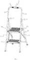
- FIG. 1illustrates a schematic diagram of a folding ladder with an armrest of the present invention.
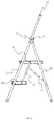
- FIG. 2illustrates a side diagram of the folding ladder with an armrest of FIG. 1 .
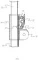
- FIG. 3illustrates a sectional diagram of the shaft sleeve portion of the folding ladder of FIG. 1 .
- FIG. 4illustrates a schematic diagram of the folding ladder of FIG. 1 with the armrest is dropped down.
- a folding ladder with an armrestcomprises two front legs 10 , two rear legs 20 , two shaft sleeves 30 and at least a footboard 40 , two shaft sleeves 30 are respectively sleeved on the top portion of the two front legs 10 , the top portion of the two rear legs 20 are respectively rotatably pivoted to the two shaft sleeves 30 , the front leg 10 and the rear leg 20 form a foldable herringbone structure through the shaft sleeve 30 , the front portion of one side of the footboard 40 is pivoted to the front leg 10 .
- the folding ladder with an armrestfurther comprises an armrest 50 , the armrest comprises two movable bars 52 and a link bar 54 , two movable bars 52 are respectively connected to the two front legs 10 in stretchable way, the link bar 54 is connected between the two movable bars 52 ;
- the shaft sleeve 30is disposed with an adjustable switch 60 to control the movable bar 52 to stretch out and draw back, the adjustable switch 60 comprises a handle 62 , a position pin 64 disposed at one end of the handle 62 and an elastic element 66 disposed at the other end of the handle 62 , the central portion of the handle 62 is rotatably pivoted to the shaft sleeve 30 ;
- the front leg 10is disposed with a through hole corresponding to the position pin, the movable bar 52 is disposed with a plurality of position holes corresponding to the position pin along the length direction; in normal state, the elastic element 66 applies an elastic force on the handle 62 to make the position pin 64 inserted in the position hole through
- the armrest 50is U shaped with an integral structure, H shape is available, or assemble structure is available as well.
- the front leg 10is a hollow tube, the movable bar 52 is inserted in the front leg 10 .
- the rear side of the shaft sleeve 30is disposed with a pair of fixing pieces 32 , the top portion of the rear leg 20 is disposed between the two fixing pieces 32 and is pivoted to the fixing pieces 32 .
- the rear side of the shaft sleeve 30is disposed with a pair of pivoting pieces 34 , the handle 62 is disposed between the two pivoting pieces 34 and is pivoted to the pivoting pieces 34 .
- the pivoting pieces 34are disposed above the fixing pieces 32 .
- this embodimentcompriss two footboards 40 disposed with space upper and lower, a connecting bar 22 is disposed with the two rear legs 20 , the connecting bar 22 supports the rear side of the bottom portion of the upper step 40 when the ladder is unfolded; it further comprises two symmetrical connecting mechanisms 70 , the connecting mechanisms 70 are used to support the rear portion of the lower footboard 40 .
- the connecting mechanism 70comprises a pull bar 72 and a swing bar 74 , two ends of the pull bar 72 are respectively rotatably pivoted to the rear portion of one side of the lower footboard 40 and the central portion of one side of the upper footboard 40 , two ends of the swing bar 74 are respectively rotatably pivoted to the middle-upper portion of the pull bar 72 and the lower portion of the rear leg 20 .
- the connecting mechanism 70is the foldable herringbone structure.
- the connecting mechanism 70can be a cross bar disposed between the two rear legs, the cross bar supports the rear portion of the lower footboard 40 when the ladder is unfolded.
- the movable bar 52can stretch out and draw back by pressing the handle 62 down, the height of the armrest 50 is thus adjustable.
Landscapes
- Engineering & Computer Science (AREA)
- Mechanical Engineering (AREA)
- Ladders (AREA)
Abstract
Description
Claims (9)
Applications Claiming Priority (3)
| Application Number | Priority Date | Filing Date | Title |
|---|---|---|---|
| CN201621283174.4 | 2016-11-28 | ||
| CN201621283174.4UCN206376733U (en) | 2016-11-28 | 2016-11-28 | A kind of folding arm rest ladder |
| CN201621283174U | 2016-11-28 |
Publications (2)
| Publication Number | Publication Date |
|---|---|
| US20180148977A1 US20180148977A1 (en) | 2018-05-31 |
| US10844660B2true US10844660B2 (en) | 2020-11-24 |
Family
ID=59406376
Family Applications (1)
| Application Number | Title | Priority Date | Filing Date |
|---|---|---|---|
| US15/786,120ActiveUS10844660B2 (en) | 2016-11-28 | 2017-10-17 | Folding ladder with armrest |
Country Status (2)
| Country | Link |
|---|---|
| US (1) | US10844660B2 (en) |
| CN (1) | CN206376733U (en) |
Cited By (6)
| Publication number | Priority date | Publication date | Assignee | Title |
|---|---|---|---|---|
| US20210010327A1 (en)* | 2019-07-08 | 2021-01-14 | Dorel Home Furnishings, Inc. | Step stool with moveable handrail |
| US11149493B2 (en)* | 2018-04-30 | 2021-10-19 | Dorel Home Furnishings, Inc. | Foldable stepladder |
| US20210372199A1 (en)* | 2008-03-07 | 2021-12-02 | Little Giant Ladder Systems, Llc | Ladders, ladder components and related methods |
| US11466516B2 (en)* | 2017-11-10 | 2022-10-11 | Little Giant Ladder Systems, Llc | Walkthrough and standoff mechanisms for ladders, ladders incorporating same and related methods |
| US20240041274A1 (en)* | 2021-04-14 | 2024-02-08 | Michael Cocilova | Toilet Training Step Ladder |
| US12398742B1 (en)* | 2025-01-17 | 2025-08-26 | Shenzhen Zhihui Youpin Technology Co., LTD | Storage pole facilitating telescopic control adjustment |
Families Citing this family (17)
| Publication number | Priority date | Publication date | Assignee | Title |
|---|---|---|---|---|
| US10941616B2 (en)* | 2017-06-19 | 2021-03-09 | Werner Co. | Step stool with rib, and method |
| CN107663943B (en)* | 2017-10-13 | 2023-08-22 | 广东群旺科技股份有限公司 | Folding scaffold |
| CN208184638U (en)* | 2018-02-26 | 2018-12-04 | 厦门新技术集成有限公司 | The double ladder of Armrest |
| CN110324439B (en)* | 2018-03-28 | 2024-07-02 | 京东方科技集团股份有限公司 | Foldable mobile terminal |
| US10837229B2 (en)* | 2018-08-21 | 2020-11-17 | Hyundai Aluminum Vina Shareholding Company | Ladder with a guardrail |
| CN210003203U (en)* | 2019-01-25 | 2020-01-31 | 江苏宙际杰智能科技股份有限公司 | Telescopic positioning structure for ladder |
| CN210195650U (en)* | 2019-01-25 | 2020-03-27 | 江苏宙际杰智能科技股份有限公司 | Lifting positioning structure of ladder tool table |
| CN111648714A (en)* | 2020-05-22 | 2020-09-11 | 高焕根 | Insulating support device for electric power construction |
| USD987118S1 (en)* | 2021-07-20 | 2023-05-23 | Kroeger Marine Construction, Inc. | Ladder assembly |
| CN216477114U (en)* | 2021-10-18 | 2022-05-10 | 江苏宙际杰智能科技股份有限公司 | Ladder with adjustable height |
| US20230371713A1 (en)* | 2022-05-18 | 2023-11-23 | The Ergo Baby Carrier, Inc. | Convertible platform for supporting a user |
| CN115363364A (en)* | 2022-09-08 | 2022-11-22 | 江苏金陵体育器材股份有限公司 | A kind of volleyball referee chair |
| CN116291172B (en)* | 2023-03-02 | 2025-06-17 | 新疆钵施然智能农机股份有限公司 | Rotatable escalator for cotton picker and cotton picker |
| USD1005526S1 (en)* | 2023-05-26 | 2023-11-21 | Fuling Ma | Ladder |
| CN222045640U (en)* | 2023-12-20 | 2024-11-22 | 厦门新技术集成有限公司 | A linked hinged herringbone folding ladder |
| USD1097206S1 (en)* | 2024-03-01 | 2025-10-07 | Luhao Leng | Ladder |
| CN222668090U (en)* | 2024-03-11 | 2025-03-25 | 厦门新技术集成有限公司 | Ladder with lifting armrests |
Citations (38)
| Publication number | Priority date | Publication date | Assignee | Title |
|---|---|---|---|---|
| US1179391A (en)* | 1915-11-09 | 1916-04-18 | Albert W Bachman | Ladder-foot. |
| US2230015A (en)* | 1939-07-03 | 1941-01-28 | Rich Ladder And Mfg Company | Knock-down load support |
| US2388892A (en)* | 1944-05-08 | 1945-11-13 | Columblan Rope Company | Ladder |
| US4320817A (en)* | 1979-09-07 | 1982-03-23 | Lear Siegler, Inc. | Combined chair and stool apparatus |
| US4485892A (en)* | 1983-07-26 | 1984-12-04 | Cosco, Inc. | Platform stool |
| US5526898A (en)* | 1994-07-06 | 1996-06-18 | Clark; Allen | Leg extension assembly |
| US5625923A (en)* | 1995-12-28 | 1997-05-06 | Huang; Li-Chu C. | Stroller length-adjustable handle |
| USD401353S (en)* | 1997-06-05 | 1998-11-17 | Werner Co. | Step ladder |
| US6012548A (en)* | 1999-02-25 | 2000-01-11 | R.M.M., Inc. | Ladder frame |
| US20020017430A1 (en)* | 2000-08-11 | 2002-02-14 | Rosko Michael Scot | Utility tray |
| US6347687B1 (en)* | 1999-09-16 | 2002-02-19 | Pt Indal Aluminum Industry Tbk. | Compact collapsible step ladder |
| US20020084143A1 (en)* | 2000-12-29 | 2002-07-04 | Roy Daniel James | Machine for leveling a ladder on an uneven surface |
| US6443261B1 (en)* | 1999-08-13 | 2002-09-03 | Cosco Management, Inc. | Step stool |
| US6536557B2 (en)* | 2001-08-09 | 2003-03-25 | Cosco Management, Inc. | Utility tray for step stool |
| US20030057022A1 (en)* | 2001-09-23 | 2003-03-27 | Luhao Leng | Hinge structure applied to folding ladder, stool and chair |
| US6550579B2 (en)* | 2000-08-11 | 2003-04-22 | Cosco Management, Inc. | Step stool |
| US20040000449A1 (en)* | 2002-06-27 | 2004-01-01 | Meeker Paul K. | Step stool with movable handrail |
| US6902035B2 (en)* | 2003-08-07 | 2005-06-07 | Cosco Management, Inc. | Step stool with step lock |
| US20050186023A1 (en)* | 2004-02-19 | 2005-08-25 | Youth Lee | Positioning structure of a beach umbrella |
| US20060102425A1 (en)* | 2004-11-17 | 2006-05-18 | Werner Co. | Stepladder folding twin-step |
| US20070284192A1 (en)* | 2006-06-07 | 2007-12-13 | Cosco Management, Inc. | Folding tray for foldable step stool |
| US20080142301A1 (en)* | 2006-12-18 | 2008-06-19 | Cosco Management, Inc. | Stepladder |
| US20100170750A1 (en)* | 2007-06-29 | 2010-07-08 | Luhao Leng | Ladder and a ladder tread |
| US20110024234A1 (en)* | 2009-07-30 | 2011-02-03 | Chen-Hsiung Lin | Ladder Chair |
| US20110209946A1 (en)* | 2008-11-06 | 2011-09-01 | New-Tec Integration(Xiamen) Co., Ltd. | Step stool |
| US20110284325A1 (en)* | 2010-05-19 | 2011-11-24 | Chen-Yu Chung | Ladder Assembly Having The Function of a Carrier |
| US8146710B2 (en)* | 2004-10-01 | 2012-04-03 | Werner Co. | Step stool latch |
| US8186481B2 (en)* | 2008-03-07 | 2012-05-29 | Wing Enterprises, Inc. | Ladders, ladder components and related methods |
| US20140190769A1 (en)* | 2013-01-10 | 2014-07-10 | Werner Co. | Stepladder with Latch Stud and Method |
| US20150068842A1 (en)* | 2013-09-06 | 2015-03-12 | Wing Enterprises, Incorporated | Adjustable ladders, ladder components and related methods |
| US9016434B2 (en)* | 2011-02-22 | 2015-04-28 | Wing Enterprises, Inc. | Ladders, ladder components and related methods |
| US9314100B1 (en)* | 2014-07-29 | 2016-04-19 | Gregory D. Logan | System and method for enhanced viewing of an event |
| US20170058930A1 (en)* | 2015-09-02 | 2017-03-02 | Evolution Technologies Inc. | Quick-release coupling assembly for upright members of a walker apparatus |
| US20170067291A1 (en)* | 2015-09-08 | 2017-03-09 | New-Tec Integration (Xiamen) Co., Ltd. | Overturn structure of a footstep of a folding ladder |
| USD797955S1 (en)* | 2015-12-15 | 2017-09-19 | Mark B. Wilbur | Step ladder with safety attachment |
| US9869125B2 (en)* | 2016-05-04 | 2018-01-16 | Tricam Industries, Inc. | Latch for ladder or step stool |
| US10138680B2 (en)* | 2015-05-26 | 2018-11-27 | Tricam Industries, Inc. | Hinged tray for ladder or step stool |
| US10487576B2 (en)* | 2016-03-04 | 2019-11-26 | Wing Enterprises, Incorporated | Adjustment mechanisms, ladders incorporating same and related methods |
- 2016
- 2016-11-28CNCN201621283174.4Upatent/CN206376733U/enactiveActive
- 2017
- 2017-10-17USUS15/786,120patent/US10844660B2/enactiveActive
Patent Citations (38)
| Publication number | Priority date | Publication date | Assignee | Title |
|---|---|---|---|---|
| US1179391A (en)* | 1915-11-09 | 1916-04-18 | Albert W Bachman | Ladder-foot. |
| US2230015A (en)* | 1939-07-03 | 1941-01-28 | Rich Ladder And Mfg Company | Knock-down load support |
| US2388892A (en)* | 1944-05-08 | 1945-11-13 | Columblan Rope Company | Ladder |
| US4320817A (en)* | 1979-09-07 | 1982-03-23 | Lear Siegler, Inc. | Combined chair and stool apparatus |
| US4485892A (en)* | 1983-07-26 | 1984-12-04 | Cosco, Inc. | Platform stool |
| US5526898A (en)* | 1994-07-06 | 1996-06-18 | Clark; Allen | Leg extension assembly |
| US5625923A (en)* | 1995-12-28 | 1997-05-06 | Huang; Li-Chu C. | Stroller length-adjustable handle |
| USD401353S (en)* | 1997-06-05 | 1998-11-17 | Werner Co. | Step ladder |
| US6012548A (en)* | 1999-02-25 | 2000-01-11 | R.M.M., Inc. | Ladder frame |
| US6443261B1 (en)* | 1999-08-13 | 2002-09-03 | Cosco Management, Inc. | Step stool |
| US6347687B1 (en)* | 1999-09-16 | 2002-02-19 | Pt Indal Aluminum Industry Tbk. | Compact collapsible step ladder |
| US20020017430A1 (en)* | 2000-08-11 | 2002-02-14 | Rosko Michael Scot | Utility tray |
| US6550579B2 (en)* | 2000-08-11 | 2003-04-22 | Cosco Management, Inc. | Step stool |
| US20020084143A1 (en)* | 2000-12-29 | 2002-07-04 | Roy Daniel James | Machine for leveling a ladder on an uneven surface |
| US6536557B2 (en)* | 2001-08-09 | 2003-03-25 | Cosco Management, Inc. | Utility tray for step stool |
| US20030057022A1 (en)* | 2001-09-23 | 2003-03-27 | Luhao Leng | Hinge structure applied to folding ladder, stool and chair |
| US20040000449A1 (en)* | 2002-06-27 | 2004-01-01 | Meeker Paul K. | Step stool with movable handrail |
| US6902035B2 (en)* | 2003-08-07 | 2005-06-07 | Cosco Management, Inc. | Step stool with step lock |
| US20050186023A1 (en)* | 2004-02-19 | 2005-08-25 | Youth Lee | Positioning structure of a beach umbrella |
| US8146710B2 (en)* | 2004-10-01 | 2012-04-03 | Werner Co. | Step stool latch |
| US20060102425A1 (en)* | 2004-11-17 | 2006-05-18 | Werner Co. | Stepladder folding twin-step |
| US20070284192A1 (en)* | 2006-06-07 | 2007-12-13 | Cosco Management, Inc. | Folding tray for foldable step stool |
| US20080142301A1 (en)* | 2006-12-18 | 2008-06-19 | Cosco Management, Inc. | Stepladder |
| US20100170750A1 (en)* | 2007-06-29 | 2010-07-08 | Luhao Leng | Ladder and a ladder tread |
| US8186481B2 (en)* | 2008-03-07 | 2012-05-29 | Wing Enterprises, Inc. | Ladders, ladder components and related methods |
| US20110209946A1 (en)* | 2008-11-06 | 2011-09-01 | New-Tec Integration(Xiamen) Co., Ltd. | Step stool |
| US20110024234A1 (en)* | 2009-07-30 | 2011-02-03 | Chen-Hsiung Lin | Ladder Chair |
| US20110284325A1 (en)* | 2010-05-19 | 2011-11-24 | Chen-Yu Chung | Ladder Assembly Having The Function of a Carrier |
| US9016434B2 (en)* | 2011-02-22 | 2015-04-28 | Wing Enterprises, Inc. | Ladders, ladder components and related methods |
| US20140190769A1 (en)* | 2013-01-10 | 2014-07-10 | Werner Co. | Stepladder with Latch Stud and Method |
| US20150068842A1 (en)* | 2013-09-06 | 2015-03-12 | Wing Enterprises, Incorporated | Adjustable ladders, ladder components and related methods |
| US9314100B1 (en)* | 2014-07-29 | 2016-04-19 | Gregory D. Logan | System and method for enhanced viewing of an event |
| US10138680B2 (en)* | 2015-05-26 | 2018-11-27 | Tricam Industries, Inc. | Hinged tray for ladder or step stool |
| US20170058930A1 (en)* | 2015-09-02 | 2017-03-02 | Evolution Technologies Inc. | Quick-release coupling assembly for upright members of a walker apparatus |
| US20170067291A1 (en)* | 2015-09-08 | 2017-03-09 | New-Tec Integration (Xiamen) Co., Ltd. | Overturn structure of a footstep of a folding ladder |
| USD797955S1 (en)* | 2015-12-15 | 2017-09-19 | Mark B. Wilbur | Step ladder with safety attachment |
| US10487576B2 (en)* | 2016-03-04 | 2019-11-26 | Wing Enterprises, Incorporated | Adjustment mechanisms, ladders incorporating same and related methods |
| US9869125B2 (en)* | 2016-05-04 | 2018-01-16 | Tricam Industries, Inc. | Latch for ladder or step stool |
Cited By (10)
| Publication number | Priority date | Publication date | Assignee | Title |
|---|---|---|---|---|
| US20210372199A1 (en)* | 2008-03-07 | 2021-12-02 | Little Giant Ladder Systems, Llc | Ladders, ladder components and related methods |
| US11788351B2 (en)* | 2008-03-07 | 2023-10-17 | Little Giant Ladder Systems, Llc | Ladders, ladder components and related methods |
| US11466516B2 (en)* | 2017-11-10 | 2022-10-11 | Little Giant Ladder Systems, Llc | Walkthrough and standoff mechanisms for ladders, ladders incorporating same and related methods |
| US11788352B2 (en) | 2017-11-10 | 2023-10-17 | Little Giant Ladder Systems, Llc | Walkthrough and standoff mechanisms for ladders, ladders incorporating same and related methods |
| US11149493B2 (en)* | 2018-04-30 | 2021-10-19 | Dorel Home Furnishings, Inc. | Foldable stepladder |
| US20210010327A1 (en)* | 2019-07-08 | 2021-01-14 | Dorel Home Furnishings, Inc. | Step stool with moveable handrail |
| US11753868B2 (en)* | 2019-07-08 | 2023-09-12 | Dorel Home Furnishings, Inc. | Step stool with moveable handrail |
| US20240041274A1 (en)* | 2021-04-14 | 2024-02-08 | Michael Cocilova | Toilet Training Step Ladder |
| US12264540B2 (en)* | 2021-04-14 | 2025-04-01 | Michael Cocilova | Toilet training step ladder |
| US12398742B1 (en)* | 2025-01-17 | 2025-08-26 | Shenzhen Zhihui Youpin Technology Co., LTD | Storage pole facilitating telescopic control adjustment |
Also Published As
| Publication number | Publication date |
|---|---|
| CN206376733U (en) | 2017-08-04 |
| US20180148977A1 (en) | 2018-05-31 |
Similar Documents
| Publication | Publication Date | Title |
|---|---|---|
| US10844660B2 (en) | Folding ladder with armrest | |
| US10786083B1 (en) | Folding chair | |
| US9016702B2 (en) | Scooter foldable seat structure | |
| US7219679B2 (en) | Dual-purpose cane | |
| US8696052B2 (en) | Folding chair | |
| US20100171342A1 (en) | Telescoping foldable chair | |
| US11219573B2 (en) | Fully foldable four-wheel walking aid | |
| US8322784B2 (en) | Collapsible chair | |
| US20150065320A1 (en) | Reformer | |
| US20140217784A1 (en) | Strong Collapsible Chair | |
| TW201336548A (en) | Treadmill | |
| US10660443B1 (en) | Folding chair | |
| US20100078279A1 (en) | Wheeled luggage and reclining chair | |
| CN104433402A (en) | Folding seat | |
| US20100013273A1 (en) | Foldable director's chair | |
| CN204015684U (en) | A kind of collapsible stool | |
| CN210299832U (en) | Walking aid | |
| US20120047650A1 (en) | Bed that is Folded and Expanded Easily and Quickly | |
| US20110079987A1 (en) | Collapsible trolley | |
| CN202202798U (en) | Ladder | |
| CN208017241U (en) | A kind of walking stick convertable into seat | |
| KR20090005670U (en) | Upright Legless Table | |
| CN214019218U (en) | A kind of multifunctional sporting goods | |
| CN213130630U (en) | Two-in-one walking aid | |
| CN204318066U (en) | Folding seat |
Legal Events
| Date | Code | Title | Description |
|---|---|---|---|
| AS | Assignment | Owner name:NEW-TEC INTEGRATION (XIAMEN) CO., LTD., CHINA Free format text:ASSIGNMENT OF ASSIGNORS INTEREST;ASSIGNOR:LENG, LUHAO;REEL/FRAME:043885/0405 Effective date:20170526 | |
| FEPP | Fee payment procedure | Free format text:ENTITY STATUS SET TO UNDISCOUNTED (ORIGINAL EVENT CODE: BIG.); ENTITY STATUS OF PATENT OWNER: SMALL ENTITY | |
| FEPP | Fee payment procedure | Free format text:ENTITY STATUS SET TO SMALL (ORIGINAL EVENT CODE: SMAL); ENTITY STATUS OF PATENT OWNER: SMALL ENTITY | |
| STPP | Information on status: patent application and granting procedure in general | Free format text:NON FINAL ACTION MAILED | |
| STPP | Information on status: patent application and granting procedure in general | Free format text:RESPONSE TO NON-FINAL OFFICE ACTION ENTERED AND FORWARDED TO EXAMINER | |
| STPP | Information on status: patent application and granting procedure in general | Free format text:FINAL REJECTION MAILED | |
| STPP | Information on status: patent application and granting procedure in general | Free format text:DOCKETED NEW CASE - READY FOR EXAMINATION | |
| STPP | Information on status: patent application and granting procedure in general | Free format text:NOTICE OF ALLOWANCE MAILED -- APPLICATION RECEIVED IN OFFICE OF PUBLICATIONS | |
| STPP | Information on status: patent application and granting procedure in general | Free format text:PUBLICATIONS -- ISSUE FEE PAYMENT VERIFIED | |
| STCF | Information on status: patent grant | Free format text:PATENTED CASE | |
| MAFP | Maintenance fee payment | Free format text:PAYMENT OF MAINTENANCE FEE, 4TH YR, SMALL ENTITY (ORIGINAL EVENT CODE: M2551); ENTITY STATUS OF PATENT OWNER: SMALL ENTITY Year of fee payment:4 |