US10844609B2 - Building rail system - Google Patents
Building rail systemDownload PDFInfo
- Publication number
- US10844609B2 US10844609B2US15/494,768US201715494768AUS10844609B2US 10844609 B2US10844609 B2US 10844609B2US 201715494768 AUS201715494768 AUS 201715494768AUS 10844609 B2US10844609 B2US 10844609B2
- Authority
- US
- United States
- Prior art keywords
- rails
- vertical
- building
- rail
- transverse
- Prior art date
- Legal status (The legal status is an assumption and is not a legal conclusion. Google has not performed a legal analysis and makes no representation as to the accuracy of the status listed.)
- Expired - Fee Related
Links
- 238000009413insulationMethods0.000claimsdescription24
- XLYOFNOQVPJJNP-UHFFFAOYSA-NwaterSubstancesOXLYOFNOQVPJJNP-UHFFFAOYSA-N0.000claimsdescription12
- 238000004078waterproofingMethods0.000claimsdescription7
- 229910052782aluminiumInorganic materials0.000claimsdescription4
- XAGFODPZIPBFFR-UHFFFAOYSA-NaluminiumChemical compound[Al]XAGFODPZIPBFFR-UHFFFAOYSA-N0.000claimsdescription4
- 230000003252repetitive effectEffects0.000claims1
- 239000000463materialSubstances0.000description5
- 229910052751metalInorganic materials0.000description5
- 239000002184metalSubstances0.000description5
- 238000009434installationMethods0.000description3
- 239000011159matrix materialSubstances0.000description2
- 238000012546transferMethods0.000description2
- 230000006978adaptationEffects0.000description1
- 230000004075alterationEffects0.000description1
- 238000010276constructionMethods0.000description1
- 230000010485copingEffects0.000description1
- 238000013461designMethods0.000description1
- 238000005259measurementMethods0.000description1
- 238000000034methodMethods0.000description1
- 238000012986modificationMethods0.000description1
- 230000004048modificationEffects0.000description1
- 239000011120plywoodSubstances0.000description1
- 230000001737promoting effectEffects0.000description1
- 229910001220stainless steelInorganic materials0.000description1
- 239000010935stainless steelSubstances0.000description1
Images


Classifications
- E—FIXED CONSTRUCTIONS
- E04—BUILDING
- E04F—FINISHING WORK ON BUILDINGS, e.g. STAIRS, FLOORS
- E04F13/00—Coverings or linings, e.g. for walls or ceilings
- E04F13/07—Coverings or linings, e.g. for walls or ceilings composed of covering or lining elements; Sub-structures therefor; Fastening means therefor
- E04F13/08—Coverings or linings, e.g. for walls or ceilings composed of covering or lining elements; Sub-structures therefor; Fastening means therefor composed of a plurality of similar covering or lining elements
- E04F13/0875—Coverings or linings, e.g. for walls or ceilings composed of covering or lining elements; Sub-structures therefor; Fastening means therefor composed of a plurality of similar covering or lining elements having a basic insulating layer and at least one covering layer
- E—FIXED CONSTRUCTIONS
- E04—BUILDING
- E04F—FINISHING WORK ON BUILDINGS, e.g. STAIRS, FLOORS
- E04F13/00—Coverings or linings, e.g. for walls or ceilings
- E04F13/07—Coverings or linings, e.g. for walls or ceilings composed of covering or lining elements; Sub-structures therefor; Fastening means therefor
- E04F13/08—Coverings or linings, e.g. for walls or ceilings composed of covering or lining elements; Sub-structures therefor; Fastening means therefor composed of a plurality of similar covering or lining elements
- E04F13/0801—Separate fastening elements
- E04F13/0803—Separate fastening elements with load-supporting elongated furring elements between wall and covering elements
- E—FIXED CONSTRUCTIONS
- E04—BUILDING
- E04B—GENERAL BUILDING CONSTRUCTIONS; WALLS, e.g. PARTITIONS; ROOFS; FLOORS; CEILINGS; INSULATION OR OTHER PROTECTION OF BUILDINGS
- E04B1/00—Constructions in general; Structures which are not restricted either to walls, e.g. partitions, or floors or ceilings or roofs
- E04B1/62—Insulation or other protection; Elements or use of specified material therefor
- E04B1/70—Drying or keeping dry, e.g. by air vents
- E—FIXED CONSTRUCTIONS
- E04—BUILDING
- E04F—FINISHING WORK ON BUILDINGS, e.g. STAIRS, FLOORS
- E04F13/00—Coverings or linings, e.g. for walls or ceilings
- E04F13/007—Outer coverings for walls with ventilating means
Definitions
- Building rail systemare used to support siding on a building.
- Building rail systemsare currently used in some continuous insulation systems.
- a common function of a building rail systemis the hanging of exterior facade panels.
- a building systemincluding a plurality of structural support members, insulation coupled to the plural of structural support members, and a building rail system supported by the plurality of structural support members.
- the building rail systemincludes a plurality of vertical rails having an interior surface facing inwardly toward a building interior and an exterior surface and a plurality of transverse rails coupled to the vertical rails.
- the plurality of transverse railshas an interior surface and an exterior surface. The exterior surfaces of the vertical rails and the exterior surfaces of the transverse rails are coplanar.
- the building systemfurther includes siding supported by the transverse rails.
- a building systemincludes a plurality of structural support members, insulation coupled to the plurality of structural support members, and a building rail system supported by the plurality of structural support members.
- the building rail systemincludes a plurality of aluminum vertical rails.
- the building systemfurther includes siding supported by the aluminum vertical rails.
- a building systemincludes a plurality of structural support members and a building wall layer including at least one of insulation, sheathing, and waterproofing.
- the building layeris coupled to the plurality of structural support members.
- the building systemfurther includes a building rail system supported by the plurality of structural support members.
- the building rail systemincludes a plurality rails positioned adjacent to the building wall layer.
- the building systemfurther includes siding supported by the rails, the siding and the building wall layer cooperating to define an air flow path therebetween, at least 60 percent of the air flow path is blocked by the plurality of rails.
- a building systemincluding a plurality of structural support members and a building wall layer including at least one of insulation, sheathing, and waterproofing.
- the building layeris coupled to the plurality of structural support members.
- the building systemfurther includes a building rail system supported by the plurality of structural support members.
- the building rail systemincludes a plurality rails positioned adjacent to the building wall layer.
- the building systemfurther includes siding supported by the rails.
- the plurality of railsdefine a plurality of traverse channels positioned to direct water between the building wall layer and siding in a transverse direction and a plurality of vertical channels positioned to direct water between the building wall layer and the siding in a vertical direction.
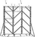
- FIG. 1is a side elevation view of an embodiment of a building rail system showing the system including large vertical rails and small transverse rails in between the vertical rails;
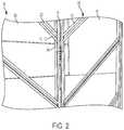
- FIG. 2is a perspective view of a portion of the system of FIG. 1 showing small rails nesting with vertical rails;
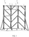
- FIG. 3is a perspective view of an embodiment of a building rail system in use with a window showing the large and small rails and horizontal facade supporting members;
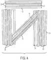
- FIG. 4is a top plan view showing a small rail at a diagonal angle, nested with two large vertical rails, and a small rail positioned horizontally above this system;
- FIG. 5is a top plan view similar to FIG. 4 showing the small diagonal rail flipped so that that bottom of the rail (as shown in FIG. 4 is) is facing upward;
- FIG. 6is a cross sectional view of the small rail (shaded) nested with the large rail;
- FIG. 7is a cross sectional view of a single small rail of FIG. 6 ;
- FIG. 8is a cross sectional view of the large rail (shaded) nested with the small rail;
- FIG. 9is a cross sectional view of a single large rail of FIG. 8 ;
- FIG. 10is a cross sectional of a large rail with a typical drip edge detail
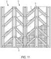
- FIG. 11is a side view of a system comprising the large vertical rails and the small transverse rails showing insulation, a waterproofing layer, and sheathing (portion of each cutaway) positioned interior of the rails;
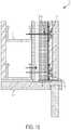
- FIG. 12is a view similar to FIG. 10 showing a large rail held in place by a top fixed connection;
- FIG. 13is a cross sectional view taken along the line 13 - 13 of FIG. 12 showing the large rail within a building exterior;
- FIG. 14is view similar to FIG. 10 showing a large rail with a building exterior
- FIG. 15is a view similar to FIG. 10 showing a large rail with a window head detail
- FIG. 16is a cross sectional view taken along the line 16 - 16 of FIG. 15 showing a large rail with a window jam detail
- FIG. 17is a top plan view of a pair of rails having a transverse rails positioned between the pair of vertical rails.
- FIGS. 1 and 2a section of a wall 10 is shown, displaying an embodiment of a rail system 20 comprising large vertical rails 14 and small transverse rails 12 .
- rails 12 , 14are comprised of extruded aluminum.
- only vertical rails 14are used, with no small rails 12 placed in between.
- small rails 12are angled at 45 degree and nest with vertical rails 14 so that a flush connection is formed, as shown in FIGS. 6 and 8 .
- a center section 22 of small rail 12rests on a bottom flange 24 of large rail 14 , and top flanges 32 of small rail 12 align with top flanges 34 of large rail 14 .
- the flush connection between vertical rails 14 and small rails 12eliminates an extra layer of space that would otherwise exist if the rails had to be offset to form a connection.
- rails 12 , 14are fastened together with stainless steel fasteners 11 and thermal washers 13 at grooves 42 , 44 (see FIGS. 7, 9 ).
- fasteners 11 and thermal washers 13secure the connection between larger rails 14 and small rails 12
- theyfasten center section 22 of small rail 12 to lower flange 32 of large rail 14 (see FIG. 2 ).
- thisis not the only means of fastening vertical rails 14 and small rails 12 to one another.
- Small rail 12 and large rail 14function to hold exterior facade panels 40 (represented by dashed rectangle in FIG. 3 ), which may be coupled to a horizontal member 15 coupled to small rail 12 and large rail 14 .
- Small rail 12 and large rail 14may be coupled to a plural of structural support members, such as interior metal studs 17 , as can be seen in more detail in FIGS. 10 and 12-16 .
- this connectionwill be made with fasteners 11 and thermal washers 13 , and a region 30 will exist between large rail 14 and metal stud 17 .
- Region 30is sized to accommodate building wall layers such as, but not limited to, insulation 16 and waterproofing 21 (see FIG. 10 ). Region 30 may allow for large areas of wall 10 to be insulated with an uninterrupted (other than fasteners 11 ) body or matrix of insulation 16 .
- wall 10may function to further restrict heat transfer that may otherwise occur through the one or more intermediate structural bodies.
- Intermediate structural bodies which facilitate high transfer of heat to and from opposing sides of wall 10may be referred to as “thermal bridges.”
- insulationhas an R-value of at least 10.
- other R-valuemay be provided, such as 4, 6, 8, 12, 13, 14, 15, 16, 18, 20, etc.
- FIG. 3another wall 110 is shown.
- a configuration of vertical rails 14 and angled small rails 12 similar to the configuration in FIGS. 1 and 2is shown in use with a window 18 .
- horizontal member 15is shown, which is an intermediate member between rail system 20 and exterior facade panels 40 (represented by dashed rectangle in FIG. 3 ) that are supported by rail system 20 .
- window frame 18is placed between vertical rails 14 , and above sections of angled small rails 12 . In other words, window frame 18 may occupy an area that would otherwise comprise additional angled small rails 12 , bit for window frame 18 .
- FIGS. 4 and 5sections of individual rails 12 , 14 , according to one embodiment, are shown.
- Vertical rails 14are displayed vertically in a way in which they may be configured in a rail system 20 .
- small rail 12is placed at a 45 degree angle between two vertical rails 14 , and small rail 12 is nested flush with vertical rails 14 so that flanges 32 of small rail 12 ( FIG. 4 ) or center section 22 of small rail 12 ( FIG. 5 ) align at an equal height to top flanges 34 of vertical rails 14 .
- FIGS. 4 and 5show how, in some embodiments, small rail 12 may be placed with its center section 22 facing either upward or downward.
- small rail 12has been rotated 180 degrees along its longitudinal axis 19 in comparison to its position in FIG. 4 .
- FIGS. 6-9cross sectional drawings of vertical rails 14 and small rails 12 are provided.
- small rail 12is shaded.
- large rail 14is shaded.
- the components in FIGS. 7 and 9are proportional with the labeled measurements being merely representative of one configuration.
- FIGS. 6 and 8illustrate the flush relationship of small rail 12 nested next to large rail 14 .
- large rail 14 and small rail 12are shown parallel in FIGS. 6 and 8 , in some embodiments they may not be parallel and may be connected at an angle with small rail 12 cut to nest evenly against large rail 14 with top flanges 24 of small rails 12 at an equal height to top flanges 34 of vertical rails 14 .
- small rail 12may be angled at 45 degrees and connected to vertical large rail 14 by fasteners 11 and thermal washers 13 .
- FIGS. 10 and 12-16are cross sectional views of a building rail system 20 .
- wall 10is shown with one embodiment of large rail 14 within it.
- rail 14is fastened to metal stud 17 with fasteners 11 and thermal washers 13 with layer of insulation 16 , layer of waterproofing 21 , and an intermediate layer 23 of a material such as densglass or plywood between rail 14 and metal stud 17 .
- large rail 14may end at a drip edge 25 with a concrete slab 27 below drip edge 25 .
- large rail 14may end at a top fixed connection with coping 29 above the top fixed connection. Referring to FIG. 14 , large rail 14 may exist within wall 10 without proximity to a drip edge or top fixed connection. Referring to FIG. 15 , in other embodiments, large rail 14 may end at window head 16 . Referring to FIG. 16 , in some embodiments, large rail 14 may be placed directly next to window frame 18 .
- small rails 12include two exterior channels 46 and one interior channel 47 .
- channels 46 , 47create gutters that direct water that penetrates through or around façade panels 40 .
- Channels 46 , 47direct this water toward vertical rails 14 .
- vertical rails 14include channels 48 that receive water from channels 46 , 47 of small rails 12 when small rails are coupled to large rails 14 .
- Channels 48create downspouts that direct water toward drip edge 25 and eventually to the ground.
- small and vertical rails 12 , 14define a gutter and downspout system that directs water that gets behind the siding, such as façade panels 40 , toward the ground so the captured water stays away from the portion of the building interior of rails 12 , 14 .
- two large rails 14are coupled to insulation panel 16 .
- Small rails 12(for simplicity only one small rail 12 is shown) are coupled to large rails 14 and siding, such as a façade panel 40 , is supported on small rail 12 .
- sidingsuch as a façade panel 40
- water that gets behind panel 40is captured by channels 46 , 47 of small rail 12 and directed to channel 48 of either (or both) of larger rails 14 depending on the angle at which small rail 12 is installed on larger rails 14 .
- a gap 50exists between insulation panel 16 and façade panel 40 creating a potential air flow path between large rails 14 having a cross-sectional area equal to a distance between insulation panel 16 and façade 40 and a distance between centers of large rails 14 .
- the cross-sectional areais about 11.2 square inches.
- Vertical rails 14 and transverse rails 12fill a majority of this cross-sectional area to restrict the flow of air between insulation panel 16 and façade panel 40 .
- at gap of about 1.15 square inches (0.1 inches wide and 11.5 inches long)exists between transverse rail 12 and installation panel 16 .
- Channels 48have an area of about 0.325 square inches (0.65 inches by 0.5 inches) each (or 0.65 square inches per vertical rail 14 ) and center channels 52 of vertical rails are about 0.45 square inches (0.74 inches by 0.6 inches).
- about 2.25 square inchesremains open after vertical and transverse rails 14 , 12 are installed.
- about 20% of the cross-sectional area/air flow pathremains open and about 80% is closed by vertical and transverse rails 14 , 12 .
- more or less of the cross-sectional area/air flow path between insulation panel 16 (or whatever layer of material vertical rails 14 are attached to) and façade panel 40 (or whatever layer of material is supported on vertical and transverse rails 14 , 12 )is filled by rails 12 , 14 .
- 20%remains open as discussed above, 0%, 1%, 2%, 3%, 5%, 7%, 10%, 15%, 25%, 30%, 40%, 50%, etc. may remain open.
- channels 48 of vertical rails 14About 6% of the cross-sectional area/air flow path that remains open is provided by channels 48 of vertical rails 14 and permits water to flow down vertical rails 14 to drip edge 25 and eventually the ground as discussed above.
- more or less of the cross-sectional area/air flow path between insulation panel 16 (or whatever layer of material vertical rails 14 are attached to) and façade panel 40 (or whatever layer of material is supported on vertical and transverse rails 14 , 12 )remains open because of channels 48 of vertical rails 14 .
- 0%, 1%, 2%, 3%, 5%, 7%, 10%, etc.may remain open because of channels 48 of rails 14 .
- the terms “vertical rails” and “small rails”may not necessarily refer to the geometric or physical characteristics of the rails.
- the vertical railsmay have one or more dimensions, such as length, width, or height that are less than the one or more corresponding dimension of the small rails.
Landscapes
- Engineering & Computer Science (AREA)
- Architecture (AREA)
- Civil Engineering (AREA)
- Structural Engineering (AREA)
- Physics & Mathematics (AREA)
- Electromagnetism (AREA)
- Finishing Walls (AREA)
- Building Environments (AREA)
Abstract
Description
Claims (8)
Priority Applications (2)
| Application Number | Priority Date | Filing Date | Title |
|---|---|---|---|
| US15/494,768US10844609B2 (en) | 2016-04-22 | 2017-04-24 | Building rail system |
| US17/101,566US20210071427A1 (en) | 2016-04-22 | 2020-11-23 | Building rail system |
Applications Claiming Priority (2)
| Application Number | Priority Date | Filing Date | Title |
|---|---|---|---|
| US201662326235P | 2016-04-22 | 2016-04-22 | |
| US15/494,768US10844609B2 (en) | 2016-04-22 | 2017-04-24 | Building rail system |
Related Child Applications (1)
| Application Number | Title | Priority Date | Filing Date |
|---|---|---|---|
| US17/101,566ContinuationUS20210071427A1 (en) | 2016-04-22 | 2020-11-23 | Building rail system |
Publications (2)
| Publication Number | Publication Date |
|---|---|
| US20170306620A1 US20170306620A1 (en) | 2017-10-26 |
| US10844609B2true US10844609B2 (en) | 2020-11-24 |
Family
ID=60090017
Family Applications (2)
| Application Number | Title | Priority Date | Filing Date |
|---|---|---|---|
| US15/494,768Expired - Fee RelatedUS10844609B2 (en) | 2016-04-22 | 2017-04-24 | Building rail system |
| US17/101,566AbandonedUS20210071427A1 (en) | 2016-04-22 | 2020-11-23 | Building rail system |
Family Applications After (1)
| Application Number | Title | Priority Date | Filing Date |
|---|---|---|---|
| US17/101,566AbandonedUS20210071427A1 (en) | 2016-04-22 | 2020-11-23 | Building rail system |
Country Status (1)
| Country | Link |
|---|---|
| US (2) | US10844609B2 (en) |
Citations (111)
| Publication number | Priority date | Publication date | Assignee | Title |
|---|---|---|---|---|
| US2221001A (en)* | 1936-10-27 | 1940-11-12 | Johns Manville | Ventilating ceiling |
| US2559869A (en)* | 1948-08-25 | 1951-07-10 | Frazer W Gay | House structure and heating system therefor |
| US2559868A (en)* | 1948-08-25 | 1951-07-10 | Frazer W Gay | House structure adapted for interior temperature controls |
| US2559871A (en)* | 1949-08-24 | 1951-07-10 | Frazer W Gay | House structure and heating system therefor |
| US3160248A (en)* | 1961-05-29 | 1964-12-08 | Galajikian Haig | Prefabricated expandable building construction |
| US3233373A (en)* | 1959-11-30 | 1966-02-08 | Behlen Mfg Co | Strut system and building covering unit combination |
| US3327438A (en)* | 1964-02-24 | 1967-06-27 | Westinghouse Electric Corp | Building construction |
| US3353316A (en)* | 1965-06-01 | 1967-11-21 | Edward T Berg | Panel-covered structures |
| US3359697A (en)* | 1964-03-05 | 1967-12-26 | Luminous Ceilings Inc | Suspended ceilings |
| US3503166A (en)* | 1968-03-22 | 1970-03-31 | Yosh Nakazawa & Associates Inc | Architectural system of interior modular construction |
| US3534516A (en)* | 1966-12-17 | 1970-10-20 | Richard A Cooper | Demountable partition wall |
| US3628299A (en)* | 1970-06-11 | 1971-12-21 | Yoshio Nakazawa | Architectural system of interior modular construction |
| US3685235A (en)* | 1970-09-21 | 1972-08-22 | Bajer Ind Inc | Suspended ceiling system including a grid network |
| US3774366A (en)* | 1970-11-17 | 1973-11-27 | W Baker | Box beam structures and connections for beam-supported structures |
| US3998016A (en)* | 1975-03-13 | 1976-12-21 | H. H. Robertson Company | Blow-in/blow-out wall structure |
| US4073108A (en)* | 1974-04-25 | 1978-02-14 | Williams Arthur C | Method and apparatus for rigidly interconnected ceiling and wall construction |
| US4185422A (en)* | 1977-10-03 | 1980-01-29 | Ready Metal Manufacturing Company | Free standing wall |
| US5007222A (en)* | 1988-11-14 | 1991-04-16 | Raymond Harry W | Foamed building panel including an internally mounted stud |
| US5065557A (en)* | 1990-11-01 | 1991-11-19 | Robertson-Ceco Corporation | Curtain wall system with individually removable wall panels |
| US5634300A (en)* | 1994-03-10 | 1997-06-03 | Plascore Inc. | Wall system employing grooved posts, connector blocks and T-bolt receiving battens |
| US5946870A (en)* | 1998-04-14 | 1999-09-07 | Vinyl Corporation | Panel support construction accessory |
| US6134847A (en)* | 1998-04-14 | 2000-10-24 | Vinyl Corporation | Construction accessory |
| US20010054263A1 (en)* | 2000-06-14 | 2001-12-27 | Coulton Michael S. | Building structure and spacer used therein |
| US6349519B1 (en)* | 1999-11-30 | 2002-02-26 | Brad F. Beller | Apparatus for securing sheeting |
| US20020029535A1 (en)* | 2000-09-14 | 2002-03-14 | William Loper | Water draining exterior wall structure |
| US20020108333A1 (en)* | 2000-12-16 | 2002-08-15 | Clayton Stephen J. | Wall and roof drainage apparatus, method, and tool |
| US6546684B2 (en)* | 1998-04-15 | 2003-04-15 | Steelcase Development Corporation | Partition panel |
| US6557310B2 (en)* | 2000-06-09 | 2003-05-06 | Smed International, Inc. | Interior space-dividing wall system |
| US20030177708A1 (en)* | 2002-03-20 | 2003-09-25 | Gatherum Roy Dean | Flashing for foundation/exterior treatment interface |
| US20040045235A1 (en)* | 2000-12-29 | 2004-03-11 | Wolfgang Ley | Facade and/or roof including a sealing strip with a filling piece |
| US6745527B1 (en)* | 1999-10-08 | 2004-06-08 | Diversified Panel Systems, Inc. | Curtain wall support method and apparatus |
| US6748710B2 (en)* | 2002-03-29 | 2004-06-15 | Steelcase Development Corporation | Partition trim having functional aspects |
| US6748709B1 (en)* | 1999-10-08 | 2004-06-15 | Diversified Panel Systems, Inc. | Curtain wall support method and apparatus |
| US6807776B2 (en)* | 2002-03-29 | 2004-10-26 | Steelcase Development Corporation | Building outfitting system with common accessory-mounting feature |
| US20040226225A1 (en)* | 2003-05-16 | 2004-11-18 | Olk Justin S. | Water diverter |
| US20040255535A1 (en)* | 2003-06-19 | 2004-12-23 | Herren Thomas R. | Multi-purpose construction assembly and method |
| US20050060950A1 (en)* | 2003-09-22 | 2005-03-24 | Hauschildt William R. | Wall panel system |
| US6910306B2 (en)* | 1996-12-24 | 2005-06-28 | Steelcase Development Corporation | Knock-down portable partition system |
| US6951087B2 (en)* | 2001-12-21 | 2005-10-04 | Trespa International B.V. | Panel mounting system for constructing a wall |
| US20060000670A1 (en)* | 2004-07-01 | 2006-01-05 | Dodd Murray B | Prefabricated sound attenuating wall system |
| US20060011802A1 (en)* | 2002-04-24 | 2006-01-19 | Profast | Vertical casting apparatus and method |
| US20060026911A1 (en)* | 2004-11-18 | 2006-02-09 | Sutton Adam F | Footer track with moisture vent |
| US20060053727A1 (en)* | 2004-09-13 | 2006-03-16 | Composite Cooling Solutions, L.P. | Tower/frame structure and components for same |
| US20060174573A1 (en)* | 2005-02-07 | 2006-08-10 | Melencion Neil J | Melencion shear wall system |
| US20060179744A1 (en)* | 2005-01-20 | 2006-08-17 | Dan Lynch | Wall panel joint apparatus and system using same |
| US20060277854A1 (en)* | 2005-05-27 | 2006-12-14 | Construction Research & Technology Gmbh | Exterior finish system |
| US20070113499A1 (en)* | 2005-11-21 | 2007-05-24 | Williams Mark F | House wrap with integral furring strips |
| US20080104918A1 (en)* | 2004-10-14 | 2008-05-08 | James Hardie International Finance B.V. | Cavity Wall System |
| US20080163582A1 (en)* | 2004-02-27 | 2008-07-10 | James Hardie International Finance B.V. | Batten Mounting Water Management System |
| US20080163569A1 (en)* | 2007-01-10 | 2008-07-10 | Woodard Kramer E | Wall system |
| US20080196332A1 (en)* | 2007-02-15 | 2008-08-21 | Surowiecki Matt F | Sheet metal header beam |
| US7617638B1 (en)* | 2007-06-06 | 2009-11-17 | Slama Peter D | Siding system |
| US20100037549A1 (en)* | 2005-01-20 | 2010-02-18 | Lymo Construction Co., Inc. | Wall panel joint apparatus and system using same |
| US20100146893A1 (en)* | 2007-03-20 | 2010-06-17 | David Peter Dickinson | Cladding system for buildings |
| US20100229484A1 (en)* | 2007-04-18 | 2010-09-16 | James Carolan | Cladding panel |
| US20100251647A1 (en)* | 2009-04-07 | 2010-10-07 | Douglas Brent Enns | Rainscreen attachment system |
| US20100287861A1 (en)* | 2009-05-18 | 2010-11-18 | Moisture Management, Llc | Exterior wall assembly including moisture transportation feature |
| US20100287862A1 (en)* | 2009-05-18 | 2010-11-18 | Moisture Management, Llc | Exterior wall assembly including dynamic moisture removal feature |
| US20110197530A1 (en)* | 2010-01-13 | 2011-08-18 | Pacific Insulated Panel Llc | Composite insulating building panel and system and method for attaching building panels |
| US20110258944A1 (en)* | 2010-04-26 | 2011-10-27 | Marius Radoane | NP-EIFS Non-Permissive Exterior Insulation and Finish Systems concept technology and details |
| US20120137610A1 (en)* | 2010-12-06 | 2012-06-07 | Doug Knight | Modular system for cladding exterior walls of a structure and insulating the structure walls |
| US20120174503A1 (en)* | 2009-08-20 | 2012-07-12 | James Hardie Technology Limited | Building system with multi-function insulation barrier |
| US20120216471A1 (en)* | 2011-02-28 | 2012-08-30 | Kingspan Insulated Panels, Inc. | Building Wall System |
| US20120255249A1 (en)* | 2011-04-11 | 2012-10-11 | Singh Joshua George | Wall panel trim reveal system and method |
| US20120272590A1 (en)* | 2009-05-18 | 2012-11-01 | Moisture Management, Llc | Building envelope assembly including moisture transportation feature |
| US20120272598A1 (en)* | 2011-04-20 | 2012-11-01 | Deco Nat Inc. | Mortarless modular masonry siding system |
| US20120285116A1 (en)* | 2010-08-24 | 2012-11-15 | James Walker | Ventilated structural panels and method of construction with ventilated structural panels |
| US20120297725A1 (en)* | 2011-05-25 | 2012-11-29 | Exo-Tec Solutions, Inc. | Adjustable bracket for the attachment of building cladding systems |
| US20120317909A1 (en)* | 2011-06-15 | 2012-12-20 | Mackenzie Duncan | Rain screen siding system |
| US20130074432A1 (en)* | 2011-09-28 | 2013-03-28 | Romeo Ilarian Ciuperca | Insulated concrete form and method of using same |
| US20130125487A1 (en)* | 2011-05-12 | 2013-05-23 | Ross Patrick POWER | Insulation and ventilation systems for building structures |
| US20130174506A1 (en)* | 2012-01-05 | 2013-07-11 | Cascadia Windows Ltd. | Thermally insulative spacer and methods involving use of same |
| US20130205695A1 (en)* | 2011-12-07 | 2013-08-15 | Brian Geofrey Newell | Access |
| US20130205698A1 (en)* | 2010-05-28 | 2013-08-15 | The Diller Corporation | Cladding system for building laminates |
| US20130232902A1 (en)* | 2012-03-09 | 2013-09-12 | Adirondack Group, LLC | Wall Framing System |
| US20130276392A1 (en)* | 2012-03-23 | 2013-10-24 | Mortar Net Usa, Ltd. | Lath |
| US20130291465A1 (en)* | 2012-05-04 | 2013-11-07 | Garland Industries, Inc. | Vented wall girts |
| US20130312347A1 (en)* | 2009-08-20 | 2013-11-28 | James Hardie Technology Limited | Building system with multi-function insulation barrier |
| US20140026510A1 (en)* | 2012-07-26 | 2014-01-30 | John David KUBASSEK | Thermal clip system and apparatus for a building wall assembly |
| US20140090323A1 (en)* | 2012-10-03 | 2014-04-03 | Kingspan Insulated Panels, Inc. (USA) | Building Wall Panel |
| US20140124291A1 (en)* | 2012-06-27 | 2014-05-08 | Usg Interiors, Llc | Gypsum-panel acoustical monolithic ceiling |
| US20140224459A1 (en)* | 2011-09-02 | 2014-08-14 | Beji Sasaki | Exterior heat insultation cover panel |
| US8910441B1 (en)* | 2013-06-18 | 2014-12-16 | Kenneth Hunter | Cladding attachment system to enable an exterior continuous insulation barrier |
| US8919068B2 (en)* | 2012-07-05 | 2014-12-30 | Pergo (Europe) Ab | Devices, systems, and methods for exterior flooring |
| US20150013258A1 (en)* | 2012-02-14 | 2015-01-15 | Vireo Llc | Structural panels, cladding assemblies and components |
| US20150020468A1 (en)* | 2013-07-16 | 2015-01-22 | Benjamin D. Wickstrom | Cleanroom wall panel system, and method |
| US20150052840A1 (en)* | 2013-04-23 | 2015-02-26 | MOTO Extrusions, Inc. | Multi-Layered Cladding Frame System |
| US20150128518A1 (en)* | 2013-03-14 | 2015-05-14 | Modern Framing Systems, LLC | Modular system for continuously insulating exterior walls of a structure and securing exterior cladding to the structure |
| US20150128512A1 (en)* | 2013-11-11 | 2015-05-14 | Hydrogard, LLC | System and method for waterproofing below-grade wall structures |
| US20150143763A1 (en)* | 2012-02-29 | 2015-05-28 | DIRTT ENVIRONMENTAL SOLUTIONS, LTD. Limited Liability Company | Modular in-wall functional conduits |
| US9115489B2 (en)* | 2012-02-07 | 2015-08-25 | Techniwood International | System for attaching a panel to a bearing structure element |
| US20150275509A1 (en)* | 2014-03-28 | 2015-10-01 | Romeo Ilarian Ciuperca | Insulated reinforced foam sheathing, reinforced vapor permeable air barrier foam panel and method of making and using same |
| US20150359329A1 (en)* | 2014-06-13 | 2015-12-17 | Environmental Compliance Solutions, Llc | Adjustable rack and method of making and using the same |
| US20150361653A1 (en)* | 2014-06-13 | 2015-12-17 | Owens Corning Intellectual Capital, Llc | Building insulation system |
| US20160024788A1 (en)* | 2013-05-03 | 2016-01-28 | Ibacos, Inc. | Water-Management System |
| US20160040425A1 (en)* | 2014-08-05 | 2016-02-11 | Kamran Farahmandpour | Façade Wall Attachment System |
| US20160053494A1 (en)* | 2013-05-02 | 2016-02-25 | Donald George White | Thermal Break Wall Systems And Thermal Adjustable Clip |
| US20160069067A1 (en)* | 2014-09-09 | 2016-03-10 | Romeo Ilarian Ciuperca | Insulated reinforced foam sheathing, reinforced elastomeric vapor permeable air barrier foam panel and method of making and using same |
| US20160145875A1 (en)* | 2014-10-15 | 2016-05-26 | Eclad Usa, Inc. | Undercut Clip Anchor System for Cladding of Materials |
| US20160177565A1 (en)* | 2014-12-18 | 2016-06-23 | Dorma Deutschland Gmbh | Sliding wall system |
| US20160201314A1 (en)* | 2014-12-01 | 2016-07-14 | Michael Hatzinikolas | Support bracket assembly and method |
| US9441371B1 (en)* | 2012-09-14 | 2016-09-13 | Daniel J. Harkins | Building insulation system |
| US20170037619A1 (en)* | 2014-10-10 | 2017-02-09 | Keith Dietzen | Metal wall frame assembly |
| US20170159293A1 (en)* | 2015-12-04 | 2017-06-08 | Robert Haley | Z-shaped Girts To Prevent Thermal Bridging |
| US20170191265A1 (en)* | 2015-12-11 | 2017-07-06 | Sustainable Holdings, Inc. | Track and panel building system |
| US20170204615A1 (en)* | 2015-02-10 | 2017-07-20 | James Reid Gulnick | Attachment brackets for panel mounting |
| US20170226734A1 (en)* | 2013-05-22 | 2017-08-10 | Johns Manville | Continuous wall assemblies and methods |
| US20170254069A1 (en)* | 2016-03-02 | 2017-09-07 | Designstone Pty Ltd | Wall Construction |
| US20170254091A1 (en)* | 2016-03-01 | 2017-09-07 | Denis P. Friel | Weep screed |
| US9856642B2 (en)* | 2015-10-05 | 2018-01-02 | Michael Wayne Ukrainetz | Corrugated furring strips and use of same in upright wall structures |
| US9879400B1 (en)* | 2016-07-07 | 2018-01-30 | Robert P. Walker | Device and method for foundation drainage |
- 2017
- 2017-04-24USUS15/494,768patent/US10844609B2/ennot_activeExpired - Fee Related
- 2020
- 2020-11-23USUS17/101,566patent/US20210071427A1/ennot_activeAbandoned
Patent Citations (114)
| Publication number | Priority date | Publication date | Assignee | Title |
|---|---|---|---|---|
| US2221001A (en)* | 1936-10-27 | 1940-11-12 | Johns Manville | Ventilating ceiling |
| US2559869A (en)* | 1948-08-25 | 1951-07-10 | Frazer W Gay | House structure and heating system therefor |
| US2559868A (en)* | 1948-08-25 | 1951-07-10 | Frazer W Gay | House structure adapted for interior temperature controls |
| US2559871A (en)* | 1949-08-24 | 1951-07-10 | Frazer W Gay | House structure and heating system therefor |
| US3233373A (en)* | 1959-11-30 | 1966-02-08 | Behlen Mfg Co | Strut system and building covering unit combination |
| US3160248A (en)* | 1961-05-29 | 1964-12-08 | Galajikian Haig | Prefabricated expandable building construction |
| US3327438A (en)* | 1964-02-24 | 1967-06-27 | Westinghouse Electric Corp | Building construction |
| US3359697A (en)* | 1964-03-05 | 1967-12-26 | Luminous Ceilings Inc | Suspended ceilings |
| US3353316A (en)* | 1965-06-01 | 1967-11-21 | Edward T Berg | Panel-covered structures |
| US3534516A (en)* | 1966-12-17 | 1970-10-20 | Richard A Cooper | Demountable partition wall |
| US3503166A (en)* | 1968-03-22 | 1970-03-31 | Yosh Nakazawa & Associates Inc | Architectural system of interior modular construction |
| US3628299A (en)* | 1970-06-11 | 1971-12-21 | Yoshio Nakazawa | Architectural system of interior modular construction |
| US3685235A (en)* | 1970-09-21 | 1972-08-22 | Bajer Ind Inc | Suspended ceiling system including a grid network |
| US3774366A (en)* | 1970-11-17 | 1973-11-27 | W Baker | Box beam structures and connections for beam-supported structures |
| US4073108A (en)* | 1974-04-25 | 1978-02-14 | Williams Arthur C | Method and apparatus for rigidly interconnected ceiling and wall construction |
| US3998016A (en)* | 1975-03-13 | 1976-12-21 | H. H. Robertson Company | Blow-in/blow-out wall structure |
| US4185422A (en)* | 1977-10-03 | 1980-01-29 | Ready Metal Manufacturing Company | Free standing wall |
| US5007222A (en)* | 1988-11-14 | 1991-04-16 | Raymond Harry W | Foamed building panel including an internally mounted stud |
| US5065557A (en)* | 1990-11-01 | 1991-11-19 | Robertson-Ceco Corporation | Curtain wall system with individually removable wall panels |
| US5634300A (en)* | 1994-03-10 | 1997-06-03 | Plascore Inc. | Wall system employing grooved posts, connector blocks and T-bolt receiving battens |
| US6910306B2 (en)* | 1996-12-24 | 2005-06-28 | Steelcase Development Corporation | Knock-down portable partition system |
| US5946870A (en)* | 1998-04-14 | 1999-09-07 | Vinyl Corporation | Panel support construction accessory |
| US6134847A (en)* | 1998-04-14 | 2000-10-24 | Vinyl Corporation | Construction accessory |
| US6546684B2 (en)* | 1998-04-15 | 2003-04-15 | Steelcase Development Corporation | Partition panel |
| US6745527B1 (en)* | 1999-10-08 | 2004-06-08 | Diversified Panel Systems, Inc. | Curtain wall support method and apparatus |
| US6748709B1 (en)* | 1999-10-08 | 2004-06-15 | Diversified Panel Systems, Inc. | Curtain wall support method and apparatus |
| US6349519B1 (en)* | 1999-11-30 | 2002-02-26 | Brad F. Beller | Apparatus for securing sheeting |
| US6557310B2 (en)* | 2000-06-09 | 2003-05-06 | Smed International, Inc. | Interior space-dividing wall system |
| US20010054263A1 (en)* | 2000-06-14 | 2001-12-27 | Coulton Michael S. | Building structure and spacer used therein |
| US20020029535A1 (en)* | 2000-09-14 | 2002-03-14 | William Loper | Water draining exterior wall structure |
| US20020108333A1 (en)* | 2000-12-16 | 2002-08-15 | Clayton Stephen J. | Wall and roof drainage apparatus, method, and tool |
| US20040045235A1 (en)* | 2000-12-29 | 2004-03-11 | Wolfgang Ley | Facade and/or roof including a sealing strip with a filling piece |
| US6951087B2 (en)* | 2001-12-21 | 2005-10-04 | Trespa International B.V. | Panel mounting system for constructing a wall |
| US20030177708A1 (en)* | 2002-03-20 | 2003-09-25 | Gatherum Roy Dean | Flashing for foundation/exterior treatment interface |
| US6807776B2 (en)* | 2002-03-29 | 2004-10-26 | Steelcase Development Corporation | Building outfitting system with common accessory-mounting feature |
| US6748710B2 (en)* | 2002-03-29 | 2004-06-15 | Steelcase Development Corporation | Partition trim having functional aspects |
| US20060011802A1 (en)* | 2002-04-24 | 2006-01-19 | Profast | Vertical casting apparatus and method |
| US20040226225A1 (en)* | 2003-05-16 | 2004-11-18 | Olk Justin S. | Water diverter |
| US20040255535A1 (en)* | 2003-06-19 | 2004-12-23 | Herren Thomas R. | Multi-purpose construction assembly and method |
| US20050060950A1 (en)* | 2003-09-22 | 2005-03-24 | Hauschildt William R. | Wall panel system |
| US20080163582A1 (en)* | 2004-02-27 | 2008-07-10 | James Hardie International Finance B.V. | Batten Mounting Water Management System |
| US20060000670A1 (en)* | 2004-07-01 | 2006-01-05 | Dodd Murray B | Prefabricated sound attenuating wall system |
| US20060053727A1 (en)* | 2004-09-13 | 2006-03-16 | Composite Cooling Solutions, L.P. | Tower/frame structure and components for same |
| US20080104918A1 (en)* | 2004-10-14 | 2008-05-08 | James Hardie International Finance B.V. | Cavity Wall System |
| US20060026911A1 (en)* | 2004-11-18 | 2006-02-09 | Sutton Adam F | Footer track with moisture vent |
| US20060179744A1 (en)* | 2005-01-20 | 2006-08-17 | Dan Lynch | Wall panel joint apparatus and system using same |
| US20100037549A1 (en)* | 2005-01-20 | 2010-02-18 | Lymo Construction Co., Inc. | Wall panel joint apparatus and system using same |
| US20060174573A1 (en)* | 2005-02-07 | 2006-08-10 | Melencion Neil J | Melencion shear wall system |
| US20060277854A1 (en)* | 2005-05-27 | 2006-12-14 | Construction Research & Technology Gmbh | Exterior finish system |
| US20070113499A1 (en)* | 2005-11-21 | 2007-05-24 | Williams Mark F | House wrap with integral furring strips |
| US20080163569A1 (en)* | 2007-01-10 | 2008-07-10 | Woodard Kramer E | Wall system |
| US20080196332A1 (en)* | 2007-02-15 | 2008-08-21 | Surowiecki Matt F | Sheet metal header beam |
| US20100146893A1 (en)* | 2007-03-20 | 2010-06-17 | David Peter Dickinson | Cladding system for buildings |
| US20100229484A1 (en)* | 2007-04-18 | 2010-09-16 | James Carolan | Cladding panel |
| US7617638B1 (en)* | 2007-06-06 | 2009-11-17 | Slama Peter D | Siding system |
| US20100251647A1 (en)* | 2009-04-07 | 2010-10-07 | Douglas Brent Enns | Rainscreen attachment system |
| US20100287861A1 (en)* | 2009-05-18 | 2010-11-18 | Moisture Management, Llc | Exterior wall assembly including moisture transportation feature |
| US20120272590A1 (en)* | 2009-05-18 | 2012-11-01 | Moisture Management, Llc | Building envelope assembly including moisture transportation feature |
| US20100287862A1 (en)* | 2009-05-18 | 2010-11-18 | Moisture Management, Llc | Exterior wall assembly including dynamic moisture removal feature |
| US20120174503A1 (en)* | 2009-08-20 | 2012-07-12 | James Hardie Technology Limited | Building system with multi-function insulation barrier |
| US20130312347A1 (en)* | 2009-08-20 | 2013-11-28 | James Hardie Technology Limited | Building system with multi-function insulation barrier |
| US20110197530A1 (en)* | 2010-01-13 | 2011-08-18 | Pacific Insulated Panel Llc | Composite insulating building panel and system and method for attaching building panels |
| US20110258944A1 (en)* | 2010-04-26 | 2011-10-27 | Marius Radoane | NP-EIFS Non-Permissive Exterior Insulation and Finish Systems concept technology and details |
| US20130205698A1 (en)* | 2010-05-28 | 2013-08-15 | The Diller Corporation | Cladding system for building laminates |
| US20120285116A1 (en)* | 2010-08-24 | 2012-11-15 | James Walker | Ventilated structural panels and method of construction with ventilated structural panels |
| US20120137610A1 (en)* | 2010-12-06 | 2012-06-07 | Doug Knight | Modular system for cladding exterior walls of a structure and insulating the structure walls |
| US20120216471A1 (en)* | 2011-02-28 | 2012-08-30 | Kingspan Insulated Panels, Inc. | Building Wall System |
| US20120255249A1 (en)* | 2011-04-11 | 2012-10-11 | Singh Joshua George | Wall panel trim reveal system and method |
| US20120272598A1 (en)* | 2011-04-20 | 2012-11-01 | Deco Nat Inc. | Mortarless modular masonry siding system |
| US20130125487A1 (en)* | 2011-05-12 | 2013-05-23 | Ross Patrick POWER | Insulation and ventilation systems for building structures |
| US20120297725A1 (en)* | 2011-05-25 | 2012-11-29 | Exo-Tec Solutions, Inc. | Adjustable bracket for the attachment of building cladding systems |
| US20120317909A1 (en)* | 2011-06-15 | 2012-12-20 | Mackenzie Duncan | Rain screen siding system |
| US20140224459A1 (en)* | 2011-09-02 | 2014-08-14 | Beji Sasaki | Exterior heat insultation cover panel |
| US20130074432A1 (en)* | 2011-09-28 | 2013-03-28 | Romeo Ilarian Ciuperca | Insulated concrete form and method of using same |
| US20130205695A1 (en)* | 2011-12-07 | 2013-08-15 | Brian Geofrey Newell | Access |
| US20130174506A1 (en)* | 2012-01-05 | 2013-07-11 | Cascadia Windows Ltd. | Thermally insulative spacer and methods involving use of same |
| US9115489B2 (en)* | 2012-02-07 | 2015-08-25 | Techniwood International | System for attaching a panel to a bearing structure element |
| US20150013258A1 (en)* | 2012-02-14 | 2015-01-15 | Vireo Llc | Structural panels, cladding assemblies and components |
| US20150143763A1 (en)* | 2012-02-29 | 2015-05-28 | DIRTT ENVIRONMENTAL SOLUTIONS, LTD. Limited Liability Company | Modular in-wall functional conduits |
| US20130232902A1 (en)* | 2012-03-09 | 2013-09-12 | Adirondack Group, LLC | Wall Framing System |
| US20170167134A1 (en)* | 2012-03-09 | 2017-06-15 | Adirondack Group, LLC | Wall Framing System |
| US20130276392A1 (en)* | 2012-03-23 | 2013-10-24 | Mortar Net Usa, Ltd. | Lath |
| US20130291465A1 (en)* | 2012-05-04 | 2013-11-07 | Garland Industries, Inc. | Vented wall girts |
| US20140124291A1 (en)* | 2012-06-27 | 2014-05-08 | Usg Interiors, Llc | Gypsum-panel acoustical monolithic ceiling |
| US8919068B2 (en)* | 2012-07-05 | 2014-12-30 | Pergo (Europe) Ab | Devices, systems, and methods for exterior flooring |
| US20140026510A1 (en)* | 2012-07-26 | 2014-01-30 | John David KUBASSEK | Thermal clip system and apparatus for a building wall assembly |
| US9441371B1 (en)* | 2012-09-14 | 2016-09-13 | Daniel J. Harkins | Building insulation system |
| US20140090323A1 (en)* | 2012-10-03 | 2014-04-03 | Kingspan Insulated Panels, Inc. (USA) | Building Wall Panel |
| US9856655B2 (en)* | 2013-03-14 | 2018-01-02 | Modern Framing Systems, LLC | Modular system for continuously insulating exterior walls of a structure and securing exterior cladding to the structure |
| US20150128518A1 (en)* | 2013-03-14 | 2015-05-14 | Modern Framing Systems, LLC | Modular system for continuously insulating exterior walls of a structure and securing exterior cladding to the structure |
| US20150052840A1 (en)* | 2013-04-23 | 2015-02-26 | MOTO Extrusions, Inc. | Multi-Layered Cladding Frame System |
| US20160053494A1 (en)* | 2013-05-02 | 2016-02-25 | Donald George White | Thermal Break Wall Systems And Thermal Adjustable Clip |
| US20160024788A1 (en)* | 2013-05-03 | 2016-01-28 | Ibacos, Inc. | Water-Management System |
| US20170226734A1 (en)* | 2013-05-22 | 2017-08-10 | Johns Manville | Continuous wall assemblies and methods |
| US8910441B1 (en)* | 2013-06-18 | 2014-12-16 | Kenneth Hunter | Cladding attachment system to enable an exterior continuous insulation barrier |
| US20150020468A1 (en)* | 2013-07-16 | 2015-01-22 | Benjamin D. Wickstrom | Cleanroom wall panel system, and method |
| US20150128512A1 (en)* | 2013-11-11 | 2015-05-14 | Hydrogard, LLC | System and method for waterproofing below-grade wall structures |
| US20150275509A1 (en)* | 2014-03-28 | 2015-10-01 | Romeo Ilarian Ciuperca | Insulated reinforced foam sheathing, reinforced vapor permeable air barrier foam panel and method of making and using same |
| US20150361653A1 (en)* | 2014-06-13 | 2015-12-17 | Owens Corning Intellectual Capital, Llc | Building insulation system |
| US9755201B2 (en)* | 2014-06-13 | 2017-09-05 | Environmental Compliance Solutions, Llc | Adjustable rack and method of making and using the same |
| US20150359329A1 (en)* | 2014-06-13 | 2015-12-17 | Environmental Compliance Solutions, Llc | Adjustable rack and method of making and using the same |
| US20160040425A1 (en)* | 2014-08-05 | 2016-02-11 | Kamran Farahmandpour | Façade Wall Attachment System |
| US20160069067A1 (en)* | 2014-09-09 | 2016-03-10 | Romeo Ilarian Ciuperca | Insulated reinforced foam sheathing, reinforced elastomeric vapor permeable air barrier foam panel and method of making and using same |
| US20170037619A1 (en)* | 2014-10-10 | 2017-02-09 | Keith Dietzen | Metal wall frame assembly |
| US20160145875A1 (en)* | 2014-10-15 | 2016-05-26 | Eclad Usa, Inc. | Undercut Clip Anchor System for Cladding of Materials |
| US20160201314A1 (en)* | 2014-12-01 | 2016-07-14 | Michael Hatzinikolas | Support bracket assembly and method |
| US20160177565A1 (en)* | 2014-12-18 | 2016-06-23 | Dorma Deutschland Gmbh | Sliding wall system |
| US20170204615A1 (en)* | 2015-02-10 | 2017-07-20 | James Reid Gulnick | Attachment brackets for panel mounting |
| US9856642B2 (en)* | 2015-10-05 | 2018-01-02 | Michael Wayne Ukrainetz | Corrugated furring strips and use of same in upright wall structures |
| US20170159293A1 (en)* | 2015-12-04 | 2017-06-08 | Robert Haley | Z-shaped Girts To Prevent Thermal Bridging |
| US20170191265A1 (en)* | 2015-12-11 | 2017-07-06 | Sustainable Holdings, Inc. | Track and panel building system |
| US20170254091A1 (en)* | 2016-03-01 | 2017-09-07 | Denis P. Friel | Weep screed |
| US20170254069A1 (en)* | 2016-03-02 | 2017-09-07 | Designstone Pty Ltd | Wall Construction |
| US9879400B1 (en)* | 2016-07-07 | 2018-01-30 | Robert P. Walker | Device and method for foundation drainage |
Also Published As
| Publication number | Publication date |
|---|---|
| US20170306620A1 (en) | 2017-10-26 |
| US20210071427A1 (en) | 2021-03-11 |
Similar Documents
| Publication | Publication Date | Title |
|---|---|---|
| US8490355B2 (en) | Ventilated structural panels and method of construction with ventilated structural panels | |
| US20130291465A1 (en) | Vented wall girts | |
| US10995497B1 (en) | Furring and flashing strip system | |
| US11680403B2 (en) | Multi-purpose structural panels and systems for assembling structures | |
| US20160115690A1 (en) | An insulating wall, a column assembly therefore and a method of constructing such an insulating wall | |
| ES2250289T5 (en) | WALL OF FACADE OF BUILDING. | |
| JP6208795B2 (en) | Kasagi ventilation parts | |
| US11203876B2 (en) | Metal or alloy framed insulated building cladding system | |
| US10246882B2 (en) | Structural wall panel system | |
| US20200208399A1 (en) | Envelope Interface to Insulate a Post-Frame Building | |
| US11519182B2 (en) | Fire rated glass flooring | |
| KR101275932B1 (en) | Method for installing ALC panel to concrete slab | |
| US10844609B2 (en) | Building rail system | |
| KR102157128B1 (en) | Easily Assembled Ridge Structure | |
| KR200425116Y1 (en) | Prefab container classroom | |
| JP2020084493A (en) | Simple building | |
| CN215442346U (en) | Bay window component | |
| KR101273087B1 (en) | Method for installing alc panel to concrete slab | |
| EP2449185B1 (en) | Supplementary insulation system and a method for insulating a façade | |
| JP7005870B2 (en) | Water stop structure of the building | |
| JP2020084492A (en) | Simple building | |
| JP7193368B2 (en) | roof panel | |
| EP2639372B1 (en) | Wall structure and method for manufacturing a wall structure | |
| KR101621520B1 (en) | Installing Structure Of Fabricated Building | |
| JP6863790B2 (en) | Snow stoppers, roof structures and buildings |
Legal Events
| Date | Code | Title | Description |
|---|---|---|---|
| STPP | Information on status: patent application and granting procedure in general | Free format text:FINAL REJECTION MAILED | |
| STPP | Information on status: patent application and granting procedure in general | Free format text:DOCKETED NEW CASE - READY FOR EXAMINATION | |
| STPP | Information on status: patent application and granting procedure in general | Free format text:NON FINAL ACTION MAILED | |
| STPP | Information on status: patent application and granting procedure in general | Free format text:FINAL REJECTION MAILED | |
| STPP | Information on status: patent application and granting procedure in general | Free format text:NOTICE OF ALLOWANCE MAILED -- APPLICATION RECEIVED IN OFFICE OF PUBLICATIONS | |
| ZAAA | Notice of allowance and fees due | Free format text:ORIGINAL CODE: NOA | |
| ZAAB | Notice of allowance mailed | Free format text:ORIGINAL CODE: MN/=. | |
| STPP | Information on status: patent application and granting procedure in general | Free format text:PUBLICATIONS -- ISSUE FEE PAYMENT VERIFIED | |
| STCF | Information on status: patent grant | Free format text:PATENTED CASE | |
| FEPP | Fee payment procedure | Free format text:MAINTENANCE FEE REMINDER MAILED (ORIGINAL EVENT CODE: REM.); ENTITY STATUS OF PATENT OWNER: SMALL ENTITY | |
| LAPS | Lapse for failure to pay maintenance fees | Free format text:PATENT EXPIRED FOR FAILURE TO PAY MAINTENANCE FEES (ORIGINAL EVENT CODE: EXP.); ENTITY STATUS OF PATENT OWNER: SMALL ENTITY | |
| STCH | Information on status: patent discontinuation | Free format text:PATENT EXPIRED DUE TO NONPAYMENT OF MAINTENANCE FEES UNDER 37 CFR 1.362 | |
| FP | Lapsed due to failure to pay maintenance fee | Effective date:20241124 |