US10843913B2 - Method for sealingly closing a bottle and associated sealingly closed bottle - Google Patents
Method for sealingly closing a bottle and associated sealingly closed bottleDownload PDFInfo
- Publication number
- US10843913B2 US10843913B2US15/317,434US201515317434AUS10843913B2US 10843913 B2US10843913 B2US 10843913B2US 201515317434 AUS201515317434 AUS 201515317434AUS 10843913 B2US10843913 B2US 10843913B2
- Authority
- US
- United States
- Prior art keywords
- bottle
- cage
- annular
- capsule
- stopper
- Prior art date
- Legal status (The legal status is an assumption and is not a legal conclusion. Google has not performed a legal analysis and makes no representation as to the accuracy of the status listed.)
- Expired - Fee Related, expires
Links
- 238000000034methodMethods0.000titleclaimsabstractdescription29
- 239000002775capsuleSubstances0.000claimsabstractdescription43
- 238000005304joiningMethods0.000claimsabstractdescription9
- 239000000126substanceSubstances0.000claimsdescription13
- 239000007788liquidSubstances0.000claimsdescription8
- 238000007789sealingMethods0.000description21
- -1polyethylenePolymers0.000description6
- 229920000139polyethylene terephthalatePolymers0.000description6
- 239000005020polyethylene terephthalateSubstances0.000description6
- 239000000463materialSubstances0.000description5
- 239000004033plasticSubstances0.000description4
- 229920003023plasticPolymers0.000description4
- 229920000089Cyclic olefin copolymerPolymers0.000description3
- 239000004713Cyclic olefin copolymerSubstances0.000description3
- 239000004698PolyethyleneSubstances0.000description3
- XAGFODPZIPBFFR-UHFFFAOYSA-NaluminiumChemical compound[Al]XAGFODPZIPBFFR-UHFFFAOYSA-N0.000description3
- 229910052782aluminiumInorganic materials0.000description3
- 239000004411aluminiumSubstances0.000description3
- 229920001903high density polyethylenePolymers0.000description3
- 239000004700high-density polyethyleneSubstances0.000description3
- 229920000573polyethylenePolymers0.000description3
- 229920005644polyethylene terephthalate glycol copolymerPolymers0.000description3
- 210000002105tongueAnatomy0.000description3
- 229910000838Al alloyInorganic materials0.000description2
- 239000007769metal materialSubstances0.000description2
- 238000012986modificationMethods0.000description2
- 230000004048modificationEffects0.000description2
- 239000000843powderSubstances0.000description2
- 239000002904solventSubstances0.000description2
- 239000012815thermoplastic materialSubstances0.000description2
- 230000003313weakening effectEffects0.000description2
- NLHHRLWOUZZQLW-UHFFFAOYSA-NAcrylonitrileChemical compoundC=CC#NNLHHRLWOUZZQLW-UHFFFAOYSA-N0.000description1
- 229930182555PenicillinNatural products0.000description1
- JGSARLDLIJGVTE-MBNYWOFBSA-NPenicillin GChemical compoundN([C@H]1[C@H]2SC([C@@H](N2C1=O)C(O)=O)(C)C)C(=O)CC1=CC=CC=C1JGSARLDLIJGVTE-MBNYWOFBSA-N0.000description1
- MTAZNLWOLGHBHU-UHFFFAOYSA-Nbutadiene-styrene rubberChemical compoundC=CC=C.C=CC1=CC=CC=C1MTAZNLWOLGHBHU-UHFFFAOYSA-N0.000description1
- 230000003749cleanlinessEffects0.000description1
- 239000002537cosmeticSubstances0.000description1
- 235000015872dietary supplementNutrition0.000description1
- 239000011521glassSubstances0.000description1
- 230000036512infertilityEffects0.000description1
- 238000001746injection mouldingMethods0.000description1
- 238000003780insertionMethods0.000description1
- 230000037431insertionEffects0.000description1
- 238000002372labellingMethods0.000description1
- 238000004519manufacturing processMethods0.000description1
- 229940049954penicillinDrugs0.000description1
- 230000000717retained effectEffects0.000description1
- 238000005096rolling processMethods0.000description1
- 230000006641stabilisationEffects0.000description1
- 238000011105stabilizationMethods0.000description1
- 230000001954sterilising effectEffects0.000description1
- 238000004659sterilization and disinfectionMethods0.000description1
- 238000003860storageMethods0.000description1
Images


Classifications
- B—PERFORMING OPERATIONS; TRANSPORTING
- B65—CONVEYING; PACKING; STORING; HANDLING THIN OR FILAMENTARY MATERIAL
- B65D—CONTAINERS FOR STORAGE OR TRANSPORT OF ARTICLES OR MATERIALS, e.g. BAGS, BARRELS, BOTTLES, BOXES, CANS, CARTONS, CRATES, DRUMS, JARS, TANKS, HOPPERS, FORWARDING CONTAINERS; ACCESSORIES, CLOSURES, OR FITTINGS THEREFOR; PACKAGING ELEMENTS; PACKAGES
- B65D51/00—Closures not otherwise provided for
- B65D51/18—Arrangements of closures with protective outer cap-like covers or of two or more co-operating closures
- B—PERFORMING OPERATIONS; TRANSPORTING
- B67—OPENING, CLOSING OR CLEANING BOTTLES, JARS OR SIMILAR CONTAINERS; LIQUID HANDLING
- B67B—APPLYING CLOSURE MEMBERS TO BOTTLES JARS, OR SIMILAR CONTAINERS; OPENING CLOSED CONTAINERS
- B67B1/00—Closing bottles, jars or similar containers by applying stoppers
- B67B1/08—Securing stoppers, e.g. swing stoppers, which are held in position by associated pressure-applying means coacting with the bottle neck
- B—PERFORMING OPERATIONS; TRANSPORTING
- B65—CONVEYING; PACKING; STORING; HANDLING THIN OR FILAMENTARY MATERIAL
- B65D—CONTAINERS FOR STORAGE OR TRANSPORT OF ARTICLES OR MATERIALS, e.g. BAGS, BARRELS, BOTTLES, BOXES, CANS, CARTONS, CRATES, DRUMS, JARS, TANKS, HOPPERS, FORWARDING CONTAINERS; ACCESSORIES, CLOSURES, OR FITTINGS THEREFOR; PACKAGING ELEMENTS; PACKAGES
- B65D39/00—Closures arranged within necks or pouring openings or in discharge apertures, e.g. stoppers
- B65D39/0052—Closures arranged within necks or pouring openings or in discharge apertures, e.g. stoppers made in more than one piece
- A—HUMAN NECESSITIES
- A61—MEDICAL OR VETERINARY SCIENCE; HYGIENE
- A61J—CONTAINERS SPECIALLY ADAPTED FOR MEDICAL OR PHARMACEUTICAL PURPOSES; DEVICES OR METHODS SPECIALLY ADAPTED FOR BRINGING PHARMACEUTICAL PRODUCTS INTO PARTICULAR PHYSICAL OR ADMINISTERING FORMS; DEVICES FOR ADMINISTERING FOOD OR MEDICINES ORALLY; BABY COMFORTERS; DEVICES FOR RECEIVING SPITTLE
- A61J1/00—Containers specially adapted for medical or pharmaceutical purposes
- A61J1/14—Details; Accessories therefor
- A61J1/1406—Septums, pierceable membranes
- B—PERFORMING OPERATIONS; TRANSPORTING
- B65—CONVEYING; PACKING; STORING; HANDLING THIN OR FILAMENTARY MATERIAL
- B65D—CONTAINERS FOR STORAGE OR TRANSPORT OF ARTICLES OR MATERIALS, e.g. BAGS, BARRELS, BOTTLES, BOXES, CANS, CARTONS, CRATES, DRUMS, JARS, TANKS, HOPPERS, FORWARDING CONTAINERS; ACCESSORIES, CLOSURES, OR FITTINGS THEREFOR; PACKAGING ELEMENTS; PACKAGES
- B65D45/00—Clamping or other pressure-applying devices for securing or retaining closure members
- B65D45/32—Clamping or other pressure-applying devices for securing or retaining closure members for applying radial or radial and axial pressure, e.g. contractible bands encircling closure member
- B65D45/322—Clamping or other pressure-applying devices for securing or retaining closure members for applying radial or radial and axial pressure, e.g. contractible bands encircling closure member the clamping device being an annular member moved axially to clamp the closure by using radial pressure
- B—PERFORMING OPERATIONS; TRANSPORTING
- B65—CONVEYING; PACKING; STORING; HANDLING THIN OR FILAMENTARY MATERIAL
- B65D—CONTAINERS FOR STORAGE OR TRANSPORT OF ARTICLES OR MATERIALS, e.g. BAGS, BARRELS, BOTTLES, BOXES, CANS, CARTONS, CRATES, DRUMS, JARS, TANKS, HOPPERS, FORWARDING CONTAINERS; ACCESSORIES, CLOSURES, OR FITTINGS THEREFOR; PACKAGING ELEMENTS; PACKAGES
- B65D51/00—Closures not otherwise provided for
- B65D51/002—Closures to be pierced by an extracting-device for the contents and fixed on the container by separate retaining means
Definitions
- the present inventionrelates to the sector of systems for sealingly closing a container, for example a bottle.
- the inventionrelates to a method for sealingly closing a bottle or a similar container.
- the present inventionalso relates to a bottle sealingly closed using the aforementioned method.
- the inventionis applicable to bottles containing powders of varying kinds, injectable liquids, drinkable liquids or the like.
- the present inventionis also applicable to other (related or different) fields, for example the cosmetic sector, the food sector, the sector of food supplements or any other sector where it is required to place a substance in a safe and sealed manner inside a container.
- US 2011/0000872 A1describes a stopper device comprising a support stopper and a container provided with such a device.
- WO 2011/039004 A1describes a locking stopper for a bottle, which includes a stopper with fastening tongues.
- CA 2 577 886 A1describes a plug without an inserted seal.
- FR 2 927 316describes a closing assembly for a bottle.
- the assembled closing assemblyis associated with the bottle by inserting the closing stopper inside the mouth of the bottle.
- the stopper device according to US 2011/0000872 A1involves firstly partially inserting the stopper 2 inside the bottle mouth and then mounting the other components on the stopper.
- the stopper inserted inside the bottle mouthis not stable and rarely is aligned with the axis of the bottle. This makes the closing assembly unstable and there is the risk of not being able to exert correctly the pressure required to sealingly close the bottle.
- the device as a wholemay not be preassembled.
- the locking stopper described in WO 2011/039004 A1also involves inserting the stopper into the mouth of the bottle before sealingly closing it by exerting a certain pressure on the sealing assembly.
- the Applicanthas found in tests that the closing assembly described in FR 2 927 316 involves sealing the bottle in two separate and successive stages, in a similar or identical manner to the closing systems already currently present on the market (for example aluminium sealing stoppersules).
- the sole difference determined between the closing system described in FR 2 927 316 and the systems which are currently commercially availableis that with the first solution sealing is performed by means of pressure while with the latter it is performed by means of rolling.
- the diameter of the closing assembly according to FR 2 927 316 in most casesis greater than the diameter of the body of the bottle on which it is mounted and this creates major problems of instability during the labelling stage, during storage and during transport in the case where said bottles are moved alongside each other on high-speed production lines, consequently limiting use thereof.
- the object defined by the Applicantis to provide a method for sealingly closing a bottle by means of a simple and reliable closing assembly which may be preassembled and sealed with respect to the bottle by means of pressure in a single operation.
- the present inventionprovides a method for sealingly closing a bottle by means of a closing assembly with a cage configured so as to have a device for retaining a closing stopper and prevent it from being separated from the cage and with an inner relief configured so as to engage with the bottom edge of the collar of the bottle once closing has been completed.
- the preassembled closing assemblyis pressed directly onto the mouth of the bottle without an intermediate step during which the stopper is partially inserted inside the mouth of the bottle.
- the present inventionprovides a method for sealingly closing a bottle, the method comprising the steps of:
- the step of joining the stopper to the cagecomprises the step of pushing the stopper towards a base of said cage, forcing said elastic retaining element to retract inside a recess.
- the step of joining the cage to the capsulecomprises the step of providing a first engagement element in the capsule and a first engagement element in the cage and the step of engaging said first engagement elements with each other.
- the first engagement element of the capsulemay be disengaged from said first engagement element of the cage by exerting pressure towards the bottom of the bottle.
- the first engagement element of the capsuleengages with a second engagement element of said cage.
- the step of joining the stopper to the cageis preferably performed by keeping the open base of the cage directed upwards.
- a substanceis introduced into said bottle before aligning the closing assembly on the mouth of the bottle and before exerting pressure so as to sealingly close the bottle.
- the substanceis a substance in the liquid state.
- the present inventionenvisages a bottle sealingly closed using the method described above.
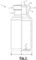
- FIG. 1shows, longitudinally sectioned, a bottle configured to be closed by means of the closing assembly according to embodiments of the present invention
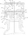
- FIG. 2shows, in a longitudinally sectioned larger-scale view, the closing assembly according to a first embodiment of the present invention, preassembled, at the start of the closing process;
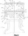
- FIG. 3shows, in a longitudinally sectioned larger-scale view, the closing assembly according to FIG. 2 at the end of the closing process
- FIG. 4shows the sequence of steps for preassembly of the closing assembly according to FIGS. 2 and 3 , filling the bottle, and closing and transporting and/or storing filled bottles;
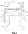
- FIG. 5shows, in a longitudinally sectioned larger-scale view, the closing assembly according to a second embodiment of the present invention, preassembled, at the start of the closing process;
- FIG. 6shows, in a longitudinally sectioned larger-scale view, the closing assembly according to FIG. 5 at the end of the closing process
- FIG. 7shows the sequence of steps for preassembly of the closing assembly according to FIGS. 5 and 6 , filling the bottle, and closing and transporting and/or storing filled bottles.
- topor “upper”, “bottom” or “lower”, “side” or “lateral”, etc.
- a component qualified as “top” or “upper”may be “bottom” or “lower” if turned upside down or rotated in another position. Therefore, these terms are not to be regarded as limiting the scope of protection.
- some componentsmay be overturned with respect to their position at the end of assembly or during use.
- the bottle 1comprises a substantially cylindrical body with a closed bottom 2 and an open mouth 3 .
- An annular collar 4namely a ring-like collar which forms an enlarged part extending radially outwards, is preferably provided in the region of the mouth 3 .
- a neck 5 with an outer diameter smaller than that of the collar 4is formed underneath the collar 4 and is connected to the bottom part of the substantially cylindrical body.
- Such a bottleis also conventionally known as a “penicillin phial”. More precisely, as also shown in FIGS.
- the annular collar 4comprises a top surface 4 a which is substantially horizontal (in reality it is slightly inclined downwards in the outward direction), a substantially vertical side surface 4 b and a bottom surface 4 c slightly inclined upwards in the outward direction.
- the various top, side and bottom surfacesare connected together by means of curved surfaces.
- the bottleis made of glass or a plastic material such as polyethylene, polyethylene terephthalate, PETG, PETE, PEHD, COC (Cyclic Olefin Copolymer) or the like.
- FIGS. 2 and 3A first type of closing assembly, which can be used with the method according to the present invention, is shown in FIGS. 2 and 3 .
- the cage 100 , the sealing stopper 200 , the capsule 300 , and the protection cap 400will be described separately. Thereafter the mutual relationship of the various components and how to assemble them will be described.
- the cage 100is in the form of an overturned cup-shaped body with a closed top base 101 (apart, possibly, for an opening 101 ′ which will be described below) and a side wall 102 which terminates in a free edge 103 .
- the side wall 102is divided up into a plurality of substantially parallel, separate, side walls which are connected together at the closed base 101 .
- a grooveis present between each separate side wall.
- the side wallis divided up into eight separate side walls.
- the inner surface of the side wall 102 of the cage 100comprises a lower annular relief 120 , preferably in the vicinity of the free edge 103 .
- the lower annular relief 120forms, in cross-section, a kind of nose radially projecting towards the axis X-X of the cage 100 .
- the outer surface of the side wall 102 of the cagecomprises preferably an upper annular spur 109 and a lower annular spur 110 .
- the upper spur 109is preferably in the vicinity of the closed base 101 .
- the lower spur 110is preferably substantially opposite to the lower annular relief 120 .
- the inner surface of the side wall 102 of the cage 102comprises an elastic retaining element, which may be in the form of one or more flexible retaining teeth 130 (for example four teeth) for retaining in position the stopper 200 which will be described below.
- Each retaining tooth 130projects in cantilever fashion and is inclined with respect to the inner surface of the side wall 102 of the cage 100 .
- the degree of inclination of the aforementioned teethmay vary depending on the requirements for use.
- each tooth 130is provided with a recess or niche 131 inside which the tooth 130 may be retracted.
- the stopper 200may be pushed towards the base 101 of the cage 100 and retained in the vicinity thereof.
- the teeth 130retract elastically inside the respective recesses or niches 131 and then return into their initial projecting position.
- the aforementioned teeth 130may be modified in terms of their form and inclination so that, in addition to retaining the stopper, they may also ensure centring of the stopper inside the cage 100 in order to allow correct positioning thereof on the mouth of the bottle.
- the upper base 101 of the cagecomprises a hole 101 ′.
- the hole 101 ′ in the upper base of the cageis a central circular hole.
- the cage 100is made of a thermoplastic material and is produced by means of injection-moulding as one piece.
- a suitable materialis, for example, polyethylene, polyethylene terephthalate, PETG, PETE, PEHD, COC, ABS (Acrilonitrile Butadiene Styrene) or the like.
- FIGS. 2 and 3show also, by way of a non-limiting example, a sealing stopper 200 .
- the sealing stoppercould be formed only by the head 210 , in the form of a relatively thick disc.
- the sealing stopper 200is made of rubber or a similar material.
- the stopper 200forms a sealing surface 211 designed to cooperate with the upper surface 4 a of the collar 4 of the bottle, so as to ensure the sealing action.
- the capsule 300has preferably the shape of an overturned cup with an upper base 301 which is substantially closed and a side wall 302 which terminates in a free edge.
- the capsule 300is made of a plastic material, but could also be formed from metallic material such as aluminium or aluminium alloy.
- the side wall 302 of the capsule 300comprises a first annular projection 309 , a second annular projection 310 , and an annular cavity 320 .
- the function of the first projection 309 , the second projection 310 , and the cavity 320will be explained below.
- the upper base 301 of the capsulemay comprise a central opening 301 ′, which is advantageously substantially circular.
- a protection cap 400is joined together with the upper base 301 of the capsule 300 , as shown in FIGS. 2 and 3 .
- the annular relief 120 of the cage 100can engage with the bottom surface of the collar
- the annular cavity 320can engage with the lower annular spur 110
- the upper annular spur 109 of the cage 100can be above and adjacent to the second annular projection 310 of the capsule 300
- the closing assemblycan remain locked to the bottle.
- the cap 400can be removed from the capsule 300 by levering it upwards, also using only the fingers of a hand.
- the cap 400is preferably made of a plastic or thermoplastic material such as polyethylene, polyethylene terephthalate, PETG, PETE, or PEHD or the like.
- a part of the top surface of the head 210 of the sealing stopper 200remains exposed, as defined by the hole 101 ′ of the cage 100 and the hole 301 ′ of the capsule 300 .
- the sealing stopper 200may thus be pierced, for example, by a needle of a syringe so as to introduce into the bottle a certain amount of a liquid (for example a solvent) and then draw off the solvent with the solute.
- the cap 400preferably comprises a circular disc 401 with a rim 402 shaped so as to surround a part of the side wall 302 of the capsule 300 .
- the external diameter of the cap 400is smaller than the diameter of the bottle.
- the cap 400comprises preferably an engaging part 403 for engagement with the edge of the central opening 301 ′ in the upper base 301 of the capsule 300 .
- the cap 400may also comprise a further projection 404 configured to penetrate until it touches the head 210 of the sealing stopper 200 such as to ensure the cleanliness and if necessary sterility thereof at the piercing point.
- the characteristic features of the cap 400may vary in shape and type of engaging system depending on the requirements.
- the sealing stopper 200is associated with the cage 100 .
- the sealing stopper 200has its shank directed upwards and the cage 100 is placed with the free edge 103 directed upwards so as to receive the head 210 of the sealing stopper 200 .
- the retaining teeth 130retract inside the respective recesses 131 and then snap back out so as to retain the sealing stopper 200 in position, as shown in the step fp- 2 .
- step fp- 3the cage 100 (together with the sealing stopper 200 ) is inserted partially inside the capsule 300 .
- This stepis preferably performed while still keeping the cage 100 (together with the sealing stopper 200 ) directed upwards.
- the cage 100is only partially inserted inside the capsule 300 so that the annular spur 109 is seated inside the annular cavity 320 .
- the cap 400has already been associated with the capsule 300 .
- the assembled closing assembly 1000comprising the cage 100 , the sealing stopper 200 , the capsule 300 , and the cap 400 , is placed inside a container, such as bottle 1 which, if necessary, may then be used for sterilization.
- the bottleis at least partially filled with a substance.
- This substancemay be any substance in any state.
- an injectable liquid substancefor example, an injectable liquid substance, a drinkable liquid substance, a powder, etc.
- step f- 2the closing assembly 1000 is fitted onto the bottle 1 in such a way that the end relief 120 presses elastically against the side surface of the bottle collar, as shown in FIG. 2 .
- the stopperdoes not play a part in stabilization of the closing assembly as in the known solutions.
- the cageis not mounted on the stopper inserted inside the bottle, but pressure is applied to the preassembled closing assembly.
- step f- 3a pressure directed downwards is exerted on the stopper and therefore on the entire closing assembly.
- the pressure P exertedis such that the bottom annular relief of the cage engages with the bottom surface of the collar and the closing assembly remains locked to the bottle.
- the step f- 4shows that the bottles may be handled such that they are straight when arranged next to each other since the diameter of the closing assembly 1000 is smaller than the diameter of the bottle body.
- FIGS. 5 and 6show a variation of the closing assembly shown in FIGS. 2 and 3 .
- the same reference numbers used for the first embodimentwill be used and the detailed description will not be repeated.
- the main differencerelates to the capsule and the absence of the cap 400 .
- the capsuleitself acts as a cap.
- the capsulemay be configured so as to be removable by means of tearing.
- this second embodimentis suitable for containing drinkable liquid substances and the stopper is formed solely by a disc without a shank.
- the capsule 300has preferably the shape of an overturned cup with an upper base which is closed and a side wall 302 which terminates in a free edge.
- the capsule 300is made of a plastic material, but could also be formed using a metallic material such as aluminium or aluminium alloy.
- the side wall 302 of the capsule 300comprises an annular projection 310 and an annular cavity 320 .
- the annular cavity 320is configured to receive the upper spur 109 of the cage during an intermediate assembly step ( FIG. 5 ).
- the annular projection 310is configured to cooperate with the upper spur 109 of the cage during the final assembly step ( FIG. 6 ).
- the free edge of the capsule 300is extended downwards, towards the body of the bottle.
- the free edgeis extended downwards with a straight section 321 along the entire perimeter of the capsule.
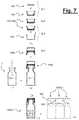
- an outwardly angled tongue 322is provided. This tongue is configured to be gripped between the fingers of a user and torn along a weakening line.
- FIG. 7an embodiment of the weakening line 323 is shown.
- FIG. 7shows one of the many ways in which the closing assembly according to FIGS. 5 and 6 may be preassembled and sealingly closed on the bottle. All the steps, both the preparatory steps and the assembly steps, are the same as those shown in FIG. 4 and will not be described again.
- the closing assembly described and shownmay be easily used, by performing a small modification to all the filling and closing machines which exist today on the world market.
- the closing assemblyin fact will be handled using the same structures (hopper, slides, etc.) which are used nowadays to convey only the rubber stopper for preassembly on the bottle, with modification of only a part of said structures depending on format.
- the closing assemblymoreover is such that it may be used on high-speed automatic machines and allows all the closing and sealing operations to be performed in a single operation with consequent savings in terms of costs, time, space, resources and personnel.
Landscapes
- Engineering & Computer Science (AREA)
- Mechanical Engineering (AREA)
- Health & Medical Sciences (AREA)
- Pharmacology & Pharmacy (AREA)
- Life Sciences & Earth Sciences (AREA)
- Animal Behavior & Ethology (AREA)
- General Health & Medical Sciences (AREA)
- Public Health (AREA)
- Veterinary Medicine (AREA)
- Closures For Containers (AREA)
- Medical Preparation Storing Or Oral Administration Devices (AREA)
- Sealing Of Jars (AREA)
Abstract
Description
- providing a cage, a closing stopper and a capsule, wherein:
- said cage is substantially cup-shaped and comprises a side wall with an inner surface comprising an annular relief;
- said capsule is cup-shaped and comprises a side wall which terminates in a free edge;
- the inner surface of the side wall of the cage comprises an elastic retaining element for retaining the closing stopper in position;
- joining the stopper to the cage and the cage to the capsule, obtaining a preassembled closing assembly;
- aligning the closing assembly on the mouth of the bottle and
- exerting a pressure so as to sealingly close the bottle, wherein the annular relief of the cage comes into contact with the bottle before the stopper comes into contact with the bottle.
Claims (13)
Applications Claiming Priority (4)
| Application Number | Priority Date | Filing Date | Title |
|---|---|---|---|
| ITMI20141102 | 2014-06-18 | ||
| ITMI2014A1102 | 2014-06-18 | ||
| ITMI2014A001102 | 2014-06-18 | ||
| PCT/IB2015/054579WO2015193830A1 (en) | 2014-06-18 | 2015-06-17 | Method for sealingly closing a bottle and associated sealingly closed bottle |
Publications (2)
| Publication Number | Publication Date |
|---|---|
| US20170121163A1 US20170121163A1 (en) | 2017-05-04 |
| US10843913B2true US10843913B2 (en) | 2020-11-24 |
Family
ID=51454796
Family Applications (1)
| Application Number | Title | Priority Date | Filing Date |
|---|---|---|---|
| US15/317,434Expired - Fee RelatedUS10843913B2 (en) | 2014-06-18 | 2015-06-17 | Method for sealingly closing a bottle and associated sealingly closed bottle |
Country Status (11)
| Country | Link |
|---|---|
| US (1) | US10843913B2 (en) |
| EP (1) | EP3157833B1 (en) |
| JP (1) | JP6628152B2 (en) |
| CN (1) | CN106458394B (en) |
| CA (1) | CA2949219C (en) |
| DK (1) | DK3157833T3 (en) |
| ES (1) | ES2692448T3 (en) |
| HU (1) | HUE041829T2 (en) |
| PL (1) | PL3157833T3 (en) |
| RU (1) | RU2676347C2 (en) |
| WO (1) | WO2015193830A1 (en) |
Cited By (3)
| Publication number | Priority date | Publication date | Assignee | Title |
|---|---|---|---|---|
| US20230036805A1 (en)* | 2020-01-16 | 2023-02-02 | A. Raymond Et Cie | Locking cover for a container having a neck, with a cap having breakable securing tabs |
| US11738915B2 (en)* | 2019-07-09 | 2023-08-29 | A. Raymond Et Cie | Locking top for vessel having a neck |
| CN116917209A (en)* | 2021-02-12 | 2023-10-20 | 毕西欧项目股份公司 | Bottles for use as containers for parenteral pharmaceutical products |
Families Citing this family (28)
| Publication number | Priority date | Publication date | Assignee | Title |
|---|---|---|---|---|
| US10093460B2 (en) | 2015-08-14 | 2018-10-09 | Yeti Coolers, Llc | Container with magnetic cap |
| USD787893S1 (en) | 2015-11-20 | 2017-05-30 | Yeti Coolers, Llc | Jug |
| US11034505B2 (en) | 2016-10-17 | 2021-06-15 | Yeti Coolers, Llc | Container and method of forming a container |
| US10959553B2 (en) | 2016-10-17 | 2021-03-30 | Yeti Coolers, Llc | Container and method of forming a container |
| CA3227282A1 (en) | 2016-10-17 | 2018-04-26 | Yeti Coolers, Llc | Container and method of forming a container |
| US10959552B2 (en) | 2016-10-17 | 2021-03-30 | Yeti Coolers, Llc | Container and method of forming a container |
| USD860716S1 (en) | 2017-03-27 | 2019-09-24 | Yeti Coolers, Llc | Container lid |
| JP6910265B2 (en)* | 2017-09-29 | 2021-07-28 | 株式会社吉野工業所 | Metering dispenser |
| CN112004756B (en)* | 2018-01-19 | 2021-11-19 | 西部制药服务有限公司(德国) | Plugging device |
| USD896572S1 (en) | 2018-08-20 | 2020-09-22 | Yeti Coolers, Llc | Container lid |
| USD883738S1 (en) | 2018-10-17 | 2020-05-12 | Yeti Coolers, Llc | Lid |
| USD883737S1 (en) | 2018-10-17 | 2020-05-12 | Yeti Coolers, Llc | Lid |
| USD897151S1 (en) | 2018-10-17 | 2020-09-29 | Yeti Coolers, Llc | Lid |
| USD871133S1 (en) | 2018-10-17 | 2019-12-31 | Yeti Coolers, Llc | Lid |
| JP7218063B2 (en)* | 2019-06-28 | 2023-02-06 | 株式会社吉野工業所 | discharge container |
| EP3995123B1 (en)* | 2019-07-02 | 2024-11-27 | Taisei Kako Co., Ltd. | Cap for a vial |
| CN110800763B (en)* | 2019-10-18 | 2021-08-31 | 黑龙江森工农化有限公司 | Storage tank for biological pesticides |
| WO2021083895A1 (en)* | 2019-10-29 | 2021-05-06 | Ceva Sante Animale | Safety outer cap for a container |
| FR3105186B1 (en)* | 2019-12-20 | 2021-11-12 | Abc Transfer | WATERPROOF CONTAINER INCLUDING A DEVICE ALLOWING REMOVABLE CONNECTION TO A SPEAKER |
| FR3105184B1 (en)* | 2019-12-20 | 2021-11-12 | Abc Transfer | REINFORCED WATERPROOF CONTAINER |
| US11389801B2 (en)* | 2020-02-03 | 2022-07-19 | Unicocell Biomed Co., Ltd. | Cell storage tube |
| CN111361853B (en)* | 2020-04-20 | 2024-09-13 | 德清县正欣包装材料有限公司 | Oral liquid bottle lid structure |
| WO2021216821A1 (en)* | 2020-04-24 | 2021-10-28 | West Pharmaceutical Services, Inc. | Containment systems |
| CN116133634A (en)* | 2020-07-08 | 2023-05-16 | 西部制药服务有限公司(德国) | Closure device |
| CN111846580B (en)* | 2020-07-23 | 2024-05-17 | 珠海市天泓科技有限公司 | Bottle stopper |
| EP4263378A1 (en)* | 2020-12-17 | 2023-10-25 | F. Hoffmann-La Roche AG | Closure system and kit |
| JP2023554049A (en)* | 2020-12-17 | 2023-12-26 | エフ・ホフマン-ラ・ロシュ・アクチェンゲゼルシャフト | Closure systems and kits |
| IT202100003182A1 (en)* | 2021-02-12 | 2022-08-12 | Bisio Progetti Spa | PLASTIC CLOSURE FOR A CONTAINER FOR INJURING PHARMACEUTICAL PRODUCTS |
Citations (12)
| Publication number | Priority date | Publication date | Assignee | Title |
|---|---|---|---|---|
| US5299702A (en)* | 1991-10-15 | 1994-04-05 | Gaplast Gmbh | Stopper for a receptacle |
| US5813554A (en)* | 1996-09-13 | 1998-09-29 | Diseno Industrial Mago, S.L. | Annular lock |
| US5957314A (en)* | 1996-04-09 | 1999-09-28 | Taisei Kako Co., Ltd. | Crown caps for drug containers |
| CA2577886A1 (en) | 2007-02-13 | 2008-08-13 | Crealise Conditionnement Inc. | Plug without inserted seal |
| FR2927316A1 (en) | 2008-02-11 | 2009-08-14 | Biocorp Rech Et Dev Sa | CLAMPING DEVICE HAVING A SUPPORT HAT AND CONTAINER EQUIPPED WITH SUCH A DEVICE |
| US20100050575A1 (en)* | 2007-02-09 | 2010-03-04 | Biocorp Recherche Et Developpement | Device for stopping a container, container equipped with such a device and method for closing a batch of such containers |
| WO2011039004A1 (en) | 2009-10-01 | 2011-04-07 | A. Raymond Et Cie | Locking cover for a vessel having a neck, including a cap having attachment tabs |
| US20120248057A1 (en)* | 2011-04-04 | 2012-10-04 | Genesis Packaging Technologies | Cap systems and methods for sealing pharmaceutical vials |
| US20130240476A1 (en)* | 2010-11-24 | 2013-09-19 | West Pharmaceutical Services Deautschland GmbH & Co. KG | Device for stopping a container, container provided with such a device, and method for closing a batch of such containers |
| US8627970B2 (en)* | 2010-01-06 | 2014-01-14 | Capitol Medical Devices, Inc. | Closure with shield, stopper, and pusher, and method for making the same |
| US20140034646A1 (en)* | 2011-04-14 | 2014-02-06 | Becton Dickinson France | Sealing device for a container |
| WO2015082354A1 (en) | 2013-12-02 | 2015-06-11 | Antonio Mutterle | Closure assembly for bottle and assembly method |
Family Cites Families (3)
| Publication number | Priority date | Publication date | Assignee | Title |
|---|---|---|---|---|
| EP0909719B1 (en)* | 1997-10-15 | 2002-07-24 | Taisei Kako Co., Ltd., | Closure for vial container |
| FR2967656B1 (en)* | 2010-11-24 | 2012-12-07 | Biocorp Rech Et Dev | DEVICE FOR CLOSING A CONTAINER AND CONTAINER EQUIPPED WITH SUCH A DEVICE |
| ITMI20110789A1 (en)* | 2011-05-09 | 2012-11-10 | Ibsa Inst Biochimique Sa | GROUP FOR SEALING BOTTLES CONTAINING INJECTABLE STERILE DRUGS OR SIMILAR SUBSTANCES, SUITABLE FOR USE IN PRODUCTION LINES OF HIGH-SPEED BOTTLES, RESPECTIVE SEALING CAP, AND CORRESPONDING SEALED BOTTLE |
- 2015
- 2015-06-17EPEP15742073.8Apatent/EP3157833B1/enactiveActive
- 2015-06-17ESES15742073.8Tpatent/ES2692448T3/enactiveActive
- 2015-06-17JPJP2016572483Apatent/JP6628152B2/ennot_activeExpired - Fee Related
- 2015-06-17WOPCT/IB2015/054579patent/WO2015193830A1/enactiveApplication Filing
- 2015-06-17CACA2949219Apatent/CA2949219C/enactiveActive
- 2015-06-17RURU2017100257Apatent/RU2676347C2/enactive
- 2015-06-17PLPL15742073Tpatent/PL3157833T3/enunknown
- 2015-06-17HUHUE15742073Apatent/HUE041829T2/enunknown
- 2015-06-17CNCN201580030790.0Apatent/CN106458394B/ennot_activeExpired - Fee Related
- 2015-06-17USUS15/317,434patent/US10843913B2/ennot_activeExpired - Fee Related
- 2015-06-17DKDK15742073.8Tpatent/DK3157833T3/enactive
Patent Citations (16)
| Publication number | Priority date | Publication date | Assignee | Title |
|---|---|---|---|---|
| US5299702A (en)* | 1991-10-15 | 1994-04-05 | Gaplast Gmbh | Stopper for a receptacle |
| US5957314A (en)* | 1996-04-09 | 1999-09-28 | Taisei Kako Co., Ltd. | Crown caps for drug containers |
| US5813554A (en)* | 1996-09-13 | 1998-09-29 | Diseno Industrial Mago, S.L. | Annular lock |
| US20100050575A1 (en)* | 2007-02-09 | 2010-03-04 | Biocorp Recherche Et Developpement | Device for stopping a container, container equipped with such a device and method for closing a batch of such containers |
| CA2577886A1 (en) | 2007-02-13 | 2008-08-13 | Crealise Conditionnement Inc. | Plug without inserted seal |
| FR2927316A1 (en) | 2008-02-11 | 2009-08-14 | Biocorp Rech Et Dev Sa | CLAMPING DEVICE HAVING A SUPPORT HAT AND CONTAINER EQUIPPED WITH SUCH A DEVICE |
| US20110000872A1 (en) | 2008-02-11 | 2011-01-06 | Biocorp Recherche Et Devloppment | Stopper device comprising a supporting cap, and container provided with such a device |
| US20120187072A1 (en)* | 2009-10-01 | 2012-07-26 | A. Raymond Et Cie | Locking cover for a vessel having a neck, including a cap having attachment tabs |
| WO2011039004A1 (en) | 2009-10-01 | 2011-04-07 | A. Raymond Et Cie | Locking cover for a vessel having a neck, including a cap having attachment tabs |
| US8684204B2 (en)* | 2009-10-01 | 2014-04-01 | A. Raymond Et Cie | Locking cover for a vessel having a neck, including a cap having attachment tabs |
| US8627970B2 (en)* | 2010-01-06 | 2014-01-14 | Capitol Medical Devices, Inc. | Closure with shield, stopper, and pusher, and method for making the same |
| US20130240476A1 (en)* | 2010-11-24 | 2013-09-19 | West Pharmaceutical Services Deautschland GmbH & Co. KG | Device for stopping a container, container provided with such a device, and method for closing a batch of such containers |
| US20120248057A1 (en)* | 2011-04-04 | 2012-10-04 | Genesis Packaging Technologies | Cap systems and methods for sealing pharmaceutical vials |
| US20130312373A1 (en) | 2011-04-04 | 2013-11-28 | Genesis Packaging Technologies | Methods for sealing pharmaceutical vials |
| US20140034646A1 (en)* | 2011-04-14 | 2014-02-06 | Becton Dickinson France | Sealing device for a container |
| WO2015082354A1 (en) | 2013-12-02 | 2015-06-11 | Antonio Mutterle | Closure assembly for bottle and assembly method |
Non-Patent Citations (1)
| Title |
|---|
| International Search Report dated Sep. 30, 2015 in PCT/IB2015/054579 filed Jun. 17, 2015. |
Cited By (5)
| Publication number | Priority date | Publication date | Assignee | Title |
|---|---|---|---|---|
| US11738915B2 (en)* | 2019-07-09 | 2023-08-29 | A. Raymond Et Cie | Locking top for vessel having a neck |
| US20230036805A1 (en)* | 2020-01-16 | 2023-02-02 | A. Raymond Et Cie | Locking cover for a container having a neck, with a cap having breakable securing tabs |
| US12109172B2 (en)* | 2020-01-16 | 2024-10-08 | A. Raymond Et Cie | Locking cover for a container having a neck, with a cap having breakable securing tabs |
| CN116917209A (en)* | 2021-02-12 | 2023-10-20 | 毕西欧项目股份公司 | Bottles for use as containers for parenteral pharmaceutical products |
| US20240400272A1 (en)* | 2021-02-12 | 2024-12-05 | Bisio Progetti S.P.A. | Bottle for a container for parenterally administrable pharmaceutical products |
Also Published As
| Publication number | Publication date |
|---|---|
| EP3157833B1 (en) | 2018-08-22 |
| RU2017100257A3 (en) | 2018-10-09 |
| JP6628152B2 (en) | 2020-01-08 |
| ES2692448T3 (en) | 2018-12-03 |
| EP3157833A1 (en) | 2017-04-26 |
| CN106458394B (en) | 2018-10-12 |
| JP2017524604A (en) | 2017-08-31 |
| RU2017100257A (en) | 2018-07-18 |
| CN106458394A (en) | 2017-02-22 |
| DK3157833T3 (en) | 2018-11-19 |
| RU2676347C2 (en) | 2018-12-28 |
| HUE041829T2 (en) | 2019-05-28 |
| CA2949219C (en) | 2022-07-05 |
| WO2015193830A1 (en) | 2015-12-23 |
| US20170121163A1 (en) | 2017-05-04 |
| PL3157833T3 (en) | 2019-01-31 |
| CA2949219A1 (en) | 2015-12-23 |
Similar Documents
| Publication | Publication Date | Title |
|---|---|---|
| US10843913B2 (en) | Method for sealingly closing a bottle and associated sealingly closed bottle | |
| CN107690409B (en) | Closing assembly for bottles, related bottle and assembly method | |
| US10144560B2 (en) | Closure assembly for bottle, associated bottle and assembly method | |
| CN102259723B (en) | Closing appliance for container and the sealing element for this device | |
| JP6210967B2 (en) | Closure cap for containers containing liquids, especially enteral nutrient solutions, and containers having such closure caps | |
| CN218705357U (en) | Tamper-evident plastic closure for a vial | |
| JP2016504126A (en) | Top lid for pharmaceutical containers | |
| JP2014233593A (en) | Male connector | |
| HK1219082B (en) | Closure assembly for bottle and assembly method |
Legal Events
| Date | Code | Title | Description |
|---|---|---|---|
| AS | Assignment | Owner name:ALTERGON SA, SWITZERLAND Free format text:ASSIGNMENT OF ASSIGNORS INTEREST;ASSIGNOR:MUTTERLE, ANTONIO;REEL/FRAME:044940/0325 Effective date:20180122 | |
| STPP | Information on status: patent application and granting procedure in general | Free format text:RESPONSE TO NON-FINAL OFFICE ACTION ENTERED AND FORWARDED TO EXAMINER | |
| STPP | Information on status: patent application and granting procedure in general | Free format text:FINAL REJECTION MAILED | |
| STPP | Information on status: patent application and granting procedure in general | Free format text:RESPONSE AFTER FINAL ACTION FORWARDED TO EXAMINER | |
| STPP | Information on status: patent application and granting procedure in general | Free format text:ADVISORY ACTION MAILED | |
| STPP | Information on status: patent application and granting procedure in general | Free format text:DOCKETED NEW CASE - READY FOR EXAMINATION | |
| STPP | Information on status: patent application and granting procedure in general | Free format text:NON FINAL ACTION MAILED | |
| STPP | Information on status: patent application and granting procedure in general | Free format text:RESPONSE AFTER FINAL ACTION FORWARDED TO EXAMINER | |
| STPP | Information on status: patent application and granting procedure in general | Free format text:NOTICE OF ALLOWANCE MAILED -- APPLICATION RECEIVED IN OFFICE OF PUBLICATIONS | |
| ZAAA | Notice of allowance and fees due | Free format text:ORIGINAL CODE: NOA | |
| ZAAB | Notice of allowance mailed | Free format text:ORIGINAL CODE: MN/=. | |
| STPP | Information on status: patent application and granting procedure in general | Free format text:PUBLICATIONS -- ISSUE FEE PAYMENT VERIFIED | |
| STCF | Information on status: patent grant | Free format text:PATENTED CASE | |
| FEPP | Fee payment procedure | Free format text:MAINTENANCE FEE REMINDER MAILED (ORIGINAL EVENT CODE: REM.); ENTITY STATUS OF PATENT OWNER: LARGE ENTITY | |
| LAPS | Lapse for failure to pay maintenance fees | Free format text:PATENT EXPIRED FOR FAILURE TO PAY MAINTENANCE FEES (ORIGINAL EVENT CODE: EXP.); ENTITY STATUS OF PATENT OWNER: LARGE ENTITY | |
| STCH | Information on status: patent discontinuation | Free format text:PATENT EXPIRED DUE TO NONPAYMENT OF MAINTENANCE FEES UNDER 37 CFR 1.362 | |
| FP | Lapsed due to failure to pay maintenance fee | Effective date:20241124 |