US10843852B2 - Lid with pylons for supporting cross beams - Google Patents
Lid with pylons for supporting cross beamsDownload PDFInfo
- Publication number
- US10843852B2 US10843852B2US15/989,941US201815989941AUS10843852B2US 10843852 B2US10843852 B2US 10843852B2US 201815989941 AUS201815989941 AUS 201815989941AUS 10843852 B2US10843852 B2US 10843852B2
- Authority
- US
- United States
- Prior art keywords
- platform
- pylons
- lid
- main body
- pylon
- Prior art date
- Legal status (The legal status is an assumption and is not a legal conclusion. Google has not performed a legal analysis and makes no representation as to the accuracy of the status listed.)
- Active, expires
Links
- 239000011120plywoodSubstances0.000claimsdescription3
- 238000010276constructionMethods0.000description6
- 239000004035construction materialSubstances0.000description6
- 238000003860storageMethods0.000description6
- 239000000463materialSubstances0.000description3
- 230000008901benefitEffects0.000description2
- -1polypropylenePolymers0.000description2
- 239000004698PolyethyleneSubstances0.000description1
- 239000004743PolypropyleneSubstances0.000description1
- 230000004075alterationEffects0.000description1
- 230000015572biosynthetic processEffects0.000description1
- 230000008878couplingEffects0.000description1
- 238000010168coupling processMethods0.000description1
- 238000005859coupling reactionMethods0.000description1
- 238000005520cutting processMethods0.000description1
- 238000002347injectionMethods0.000description1
- 239000007924injectionSubstances0.000description1
- 238000001746injection mouldingMethods0.000description1
- 238000003780insertionMethods0.000description1
- 230000037431insertionEffects0.000description1
- 238000004519manufacturing processMethods0.000description1
- 238000000034methodMethods0.000description1
- 229920000573polyethylenePolymers0.000description1
- 229920001155polypropylenePolymers0.000description1
- 239000012815thermoplastic materialSubstances0.000description1
Images


Classifications
- B—PERFORMING OPERATIONS; TRANSPORTING
- B65—CONVEYING; PACKING; STORING; HANDLING THIN OR FILAMENTARY MATERIAL
- B65D—CONTAINERS FOR STORAGE OR TRANSPORT OF ARTICLES OR MATERIALS, e.g. BAGS, BARRELS, BOTTLES, BOXES, CANS, CARTONS, CRATES, DRUMS, JARS, TANKS, HOPPERS, FORWARDING CONTAINERS; ACCESSORIES, CLOSURES, OR FITTINGS THEREFOR; PACKAGING ELEMENTS; PACKAGES
- B65D51/00—Closures not otherwise provided for
- B65D51/24—Closures not otherwise provided for combined or co-operating with auxiliary devices for non-closing purposes
- B—PERFORMING OPERATIONS; TRANSPORTING
- B65—CONVEYING; PACKING; STORING; HANDLING THIN OR FILAMENTARY MATERIAL
- B65D—CONTAINERS FOR STORAGE OR TRANSPORT OF ARTICLES OR MATERIALS, e.g. BAGS, BARRELS, BOTTLES, BOXES, CANS, CARTONS, CRATES, DRUMS, JARS, TANKS, HOPPERS, FORWARDING CONTAINERS; ACCESSORIES, CLOSURES, OR FITTINGS THEREFOR; PACKAGING ELEMENTS; PACKAGES
- B65D1/00—Rigid or semi-rigid containers having bodies formed in one piece, e.g. by casting metallic material, by moulding plastics, by blowing vitreous material, by throwing ceramic material, by moulding pulped fibrous material or by deep-drawing operations performed on sheet material
- B65D1/22—Boxes or like containers with side walls of substantial depth for enclosing contents
- B—PERFORMING OPERATIONS; TRANSPORTING
- B65—CONVEYING; PACKING; STORING; HANDLING THIN OR FILAMENTARY MATERIAL
- B65D—CONTAINERS FOR STORAGE OR TRANSPORT OF ARTICLES OR MATERIALS, e.g. BAGS, BARRELS, BOTTLES, BOXES, CANS, CARTONS, CRATES, DRUMS, JARS, TANKS, HOPPERS, FORWARDING CONTAINERS; ACCESSORIES, CLOSURES, OR FITTINGS THEREFOR; PACKAGING ELEMENTS; PACKAGES
- B65D21/00—Nestable, stackable or joinable containers; Containers of variable capacity
- B65D21/02—Containers specially shaped, or provided with fittings or attachments, to facilitate nesting, stacking, or joining together
- B65D21/0209—Containers specially shaped, or provided with fittings or attachments, to facilitate nesting, stacking, or joining together stackable or joined together one-upon-the-other in the upright or upside-down position
- B65D21/0217—Containers with a closure presenting stacking elements
- B—PERFORMING OPERATIONS; TRANSPORTING
- B65—CONVEYING; PACKING; STORING; HANDLING THIN OR FILAMENTARY MATERIAL
- B65D—CONTAINERS FOR STORAGE OR TRANSPORT OF ARTICLES OR MATERIALS, e.g. BAGS, BARRELS, BOTTLES, BOXES, CANS, CARTONS, CRATES, DRUMS, JARS, TANKS, HOPPERS, FORWARDING CONTAINERS; ACCESSORIES, CLOSURES, OR FITTINGS THEREFOR; PACKAGING ELEMENTS; PACKAGES
- B65D43/00—Lids or covers for rigid or semi-rigid containers
- B65D43/02—Removable lids or covers
- B65D43/0202—Removable lids or covers without integral tamper element
- B65D43/0214—Removable lids or covers without integral tamper element secured only by friction or gravity
- B—PERFORMING OPERATIONS; TRANSPORTING
- B65—CONVEYING; PACKING; STORING; HANDLING THIN OR FILAMENTARY MATERIAL
- B65D—CONTAINERS FOR STORAGE OR TRANSPORT OF ARTICLES OR MATERIALS, e.g. BAGS, BARRELS, BOTTLES, BOXES, CANS, CARTONS, CRATES, DRUMS, JARS, TANKS, HOPPERS, FORWARDING CONTAINERS; ACCESSORIES, CLOSURES, OR FITTINGS THEREFOR; PACKAGING ELEMENTS; PACKAGES
- B65D81/00—Containers, packaging elements, or packages, for contents presenting particular transport or storage problems, or adapted to be used for non-packaging purposes after removal of contents
- B65D81/36—Containers, packaging elements, or packages, for contents presenting particular transport or storage problems, or adapted to be used for non-packaging purposes after removal of contents adapted to be used for non-packaging purposes after removal of contents
- B65D81/365—Containers, or parts thereof, simulating or being incorporated into other items, e.g. puppet, animal, vehicle, building, dumb bells
- B—PERFORMING OPERATIONS; TRANSPORTING
- B65—CONVEYING; PACKING; STORING; HANDLING THIN OR FILAMENTARY MATERIAL
- B65D—CONTAINERS FOR STORAGE OR TRANSPORT OF ARTICLES OR MATERIALS, e.g. BAGS, BARRELS, BOTTLES, BOXES, CANS, CARTONS, CRATES, DRUMS, JARS, TANKS, HOPPERS, FORWARDING CONTAINERS; ACCESSORIES, CLOSURES, OR FITTINGS THEREFOR; PACKAGING ELEMENTS; PACKAGES
- B65D2543/00—Lids or covers essentially for box-like containers
- B65D2543/00009—Details of lids or covers for rigid or semi-rigid containers
- B65D2543/00018—Overall construction of the lid
- B65D2543/00027—Stackable lids or covers
- B—PERFORMING OPERATIONS; TRANSPORTING
- B65—CONVEYING; PACKING; STORING; HANDLING THIN OR FILAMENTARY MATERIAL
- B65D—CONTAINERS FOR STORAGE OR TRANSPORT OF ARTICLES OR MATERIALS, e.g. BAGS, BARRELS, BOTTLES, BOXES, CANS, CARTONS, CRATES, DRUMS, JARS, TANKS, HOPPERS, FORWARDING CONTAINERS; ACCESSORIES, CLOSURES, OR FITTINGS THEREFOR; PACKAGING ELEMENTS; PACKAGES
- B65D2543/00—Lids or covers essentially for box-like containers
- B65D2543/00009—Details of lids or covers for rigid or semi-rigid containers
- B65D2543/00018—Overall construction of the lid
- B65D2543/00064—Shape of the outer periphery
- B65D2543/0012—Shape of the outer periphery having straight sides, e.g. with curved corners
- B65D2543/00175—Shape of the outer periphery having straight sides, e.g. with curved corners four straight sides, e.g. trapezium or diamond
- B65D2543/00194—Shape of the outer periphery having straight sides, e.g. with curved corners four straight sides, e.g. trapezium or diamond square or rectangular
- B—PERFORMING OPERATIONS; TRANSPORTING
- B65—CONVEYING; PACKING; STORING; HANDLING THIN OR FILAMENTARY MATERIAL
- B65D—CONTAINERS FOR STORAGE OR TRANSPORT OF ARTICLES OR MATERIALS, e.g. BAGS, BARRELS, BOTTLES, BOXES, CANS, CARTONS, CRATES, DRUMS, JARS, TANKS, HOPPERS, FORWARDING CONTAINERS; ACCESSORIES, CLOSURES, OR FITTINGS THEREFOR; PACKAGING ELEMENTS; PACKAGES
- B65D2543/00—Lids or covers essentially for box-like containers
- B65D2543/00009—Details of lids or covers for rigid or semi-rigid containers
- B65D2543/00018—Overall construction of the lid
- B65D2543/00259—Materials used
- B65D2543/00296—Plastic
- B—PERFORMING OPERATIONS; TRANSPORTING
- B65—CONVEYING; PACKING; STORING; HANDLING THIN OR FILAMENTARY MATERIAL
- B65D—CONTAINERS FOR STORAGE OR TRANSPORT OF ARTICLES OR MATERIALS, e.g. BAGS, BARRELS, BOTTLES, BOXES, CANS, CARTONS, CRATES, DRUMS, JARS, TANKS, HOPPERS, FORWARDING CONTAINERS; ACCESSORIES, CLOSURES, OR FITTINGS THEREFOR; PACKAGING ELEMENTS; PACKAGES
- B65D2543/00—Lids or covers essentially for box-like containers
- B65D2543/00009—Details of lids or covers for rigid or semi-rigid containers
- B65D2543/00342—Central part of the lid
- B65D2543/00351—Dome-like
- B—PERFORMING OPERATIONS; TRANSPORTING
- B65—CONVEYING; PACKING; STORING; HANDLING THIN OR FILAMENTARY MATERIAL
- B65D—CONTAINERS FOR STORAGE OR TRANSPORT OF ARTICLES OR MATERIALS, e.g. BAGS, BARRELS, BOTTLES, BOXES, CANS, CARTONS, CRATES, DRUMS, JARS, TANKS, HOPPERS, FORWARDING CONTAINERS; ACCESSORIES, CLOSURES, OR FITTINGS THEREFOR; PACKAGING ELEMENTS; PACKAGES
- B65D2543/00—Lids or covers essentially for box-like containers
- B65D2543/00009—Details of lids or covers for rigid or semi-rigid containers
- B65D2543/00342—Central part of the lid
- B65D2543/00398—Reinforcing ribs in the central part of the closure
- B—PERFORMING OPERATIONS; TRANSPORTING
- B65—CONVEYING; PACKING; STORING; HANDLING THIN OR FILAMENTARY MATERIAL
- B65D—CONTAINERS FOR STORAGE OR TRANSPORT OF ARTICLES OR MATERIALS, e.g. BAGS, BARRELS, BOTTLES, BOXES, CANS, CARTONS, CRATES, DRUMS, JARS, TANKS, HOPPERS, FORWARDING CONTAINERS; ACCESSORIES, CLOSURES, OR FITTINGS THEREFOR; PACKAGING ELEMENTS; PACKAGES
- B65D2543/00—Lids or covers essentially for box-like containers
- B65D2543/00009—Details of lids or covers for rigid or semi-rigid containers
- B65D2543/00444—Contact between the container and the lid
- B65D2543/00481—Contact between the container and the lid on the inside or the outside of the container
- B65D2543/00555—Contact between the container and the lid on the inside or the outside of the container on both the inside and the outside
Definitions
- the present disclosurerelates to a lid and, more particularly, to a lid for a storage container or tote.
- U.S. Pat. No. 3,117,692 to Carpenter et al.illustrates containers with lids which can be stacked to a substantial height and transported without danger of toppling.
- U.S. Pat. No. 3,326,410 to Asenbauera stackable and nestable container having a length approximately equal to twice its width and having upwardly and outwardly sloping side and end walls.
- Identical containers of Asenbauermay not only be nested and conventionally stacked but also may be interlocked together in a multitude of stacked arrangements to form very stable stacked configurations.
- these known lidsare not particularly suitable for supporting construction materials and implements.
- the container lidcan serve as an alternative to a sawhorse, as well as provide access to tools without requiring removal of the lid from the container.
- a lid for a containerthat is suitable for supporting construction materials and implements, and which can serve as an alternative to a sawhorse, as well as provide access to tools without requiring removal of the lid from the container, has been surprisingly discovered.
- the lidhas a main body with an upper surface, pylons and a lip surrounding the main body.
- the upper surfaceis vertically and horizontally spaced apart from the lip of the lid.
- the pylonsare located along the perimeter of the upper surface.
- the pylonsare oriented to have a first pylon adjacent to, but spaced apart from, a second pylon.
- the first and second pylonsmay each have a plurality of platforms that are configured to receive, support and stabilize a cross beam placed in between them.
- the plurality of platformsmay include a first platform, a second platform, and a third platform, arranged in a step-like configuration.
- the first platformis horizontally spaced apart from the second platform.
- the second platformis horizontally spaced apart from the third platform.
- the first platformis also vertically spaced apart from the second platform.
- the second platformis also vertically spaced apart from the third platform.
- the main body of the lidhas at least one recess formed therein.
- the at least one recessis configured to hold particular tools.
- the main bodymay have one recess that is configured to securely hold a level, and another recess that is configured to securely hold a tape measure.
- the recess configured to hold the levelmay also be surrounded by finger-sized indents. The indents allowing a user to easily remove the level from the recess.
- the recess holding the tape measuremay have securement means configured to selectively fasten the tape measure to the lid.
- the main body of the lidmay also have a plurality of rectangular recesses that are configured to hold instruments for easy access during construction.
- the lidhas a main body with a lip and an upper surface vertically and horizontally spaced apart from the lip. Further surrounding the upper surface is a plurality of pylons, each pylon having a first platform and a second platform. The first platform is horizontally and vertically spaced apart from the second platform, and the second platform is horizontally and vertically spaced apart from the upper surface.
- the lidhas a main body with an upper surface that is vertically and horizontally spaced from the lip. Surrounding the outer perimeter of the upper surface is a plurality of pylons in the form of singular or unitary protrusions. Further formed in the upper surface is a recess. A distance between the upper surface and the lip is greater than a distance between the upper surface and a bottom of the recess.
- the lidis configured to be stacked upon another lid of the same constructions in either a nested or an unnested configuration, where the recesses are aligned in the nested configuration and are unaligned in the unnested configuration.
- FIG. 1is a top perspective view of a lid according to one embodiment of the present disclosure
- FIG. 2is a top perspective view of the lid in FIG. 1 , shown with a level and tape measure disposed recesses formed in the lid;
- FIG. 3is a top perspective view of a lid according to another embodiment of the present disclosure.
- FIG. 4is a top perspective view of a combination including a pair of lids as shown in FIG. 3 , and further show disposed on a pair of totes with three boards in different orientations supported by the lids along a width of each of the totes;
- FIG. 5is a top perspective view of the lid in FIG. 3 , shown disposed on a tote and supporting a board along a length of the tote;
- FIG. 6is a top perspective view of a lid according to a further embodiment of the present disclosure.
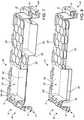
- FIG. 7is a cross-sectional top perspective view of a combination including a pair of the lids taken along section line A-A in FIG. 6 , a top one of the lids stacked on a bottom one of the lids, where the recessed portions of the top and bottom lids are spaced apart from one another and are unnested; and
- FIG. 8is a cross-sectional top perspective view of a combination including a pair of the lids taken long section line A-A in FIG. 6 , a top one of the lids stacked on a bottom one of the lids, where the recessed portions of the top and bottom lids are aligned with one another and are nested.
- relative termssuch as “lower,” “upper,” “horizontal,” “vertical,” “forward,” “rearward,” “above,” “below,” “up,” “down,” “top,” “diagonal,” and “bottom” as well as derivatives thereof (e.g., “horizontally,” “downwardly,” “upwardly,” “diagonally,” etc.) should be construed to refer to the orientation as then described or as shown in the related drawing. These relative terms are for convenience of description and do not require that the apparatus be constructed or operated in a particular orientation. Terms concerning attachments, such as “connected,” “connecting,” “coupled,” and “coupling” are used interchangeably and refer to one structure or surface being secured to another structure or surface, unless expressly described otherwise.
- FIGS. 1-2illustrate a lid 2 according to a first embodiment of the disclosure.
- the lid 2has a main body 4 with a lip 6 .
- the lidis configured to be secured with and cover a container or tote (identified as 8 ′ in FIGS. 3-5 ) for storage of items.
- the lid 2is further surrounded by a skirt 10 , which militates against the lid 2 disconnecting from the tote 8 .
- the lid 2may be substantially rectangular in shape, and have a first side 12 , a second side 14 , a third side 16 , and a fourth side 18 .
- the first side 12 of the lid 2is parallel to the second side 14 and the third side 16 is parallel to the fourth side 18 .
- the lid 2may be formed of a thermoplastic material such as polypropylene or polyethylene by an injection molding process, all as non-limiting examples.
- a thermoplastic materialsuch as polypropylene or polyethylene by an injection molding process, all as non-limiting examples.
- One of ordinary skill in the artmay also select other suitable shapes, dimensions, materials, and manufacturing methods for the lid 2 , as desired.
- the lid 2is configured to support cross beams or other items placed on the main body 4 .
- the lid 2 described hereinis configured to be stackable in both a nested configuration and an unnested configuration relative to another one of the lids 2 .
- the lid 2 of the present embodimentis also configured to support another tote 8 stacked on top of the lid 2 .
- the lid 2may have a plurality of pylons 20 .
- the pylons 20are configured to support and stabilize a cross beam disposed between adjacent ones of the pylons 20 .
- the pylons 20may be oriented in pairs along the perimeter or lip 6 of the main body 4 .
- the pylons 20may include a first pylon 22 and a second pylon 24 .
- the first pylon 22may be disposed adjacent to, but spaced apart from, the second pylon 24 .
- the first pylon 22 and the second pylon 24may each have a plurality of platforms that are vertically spaced apart from one another on a single one of the pylons 20 .
- the platforms on the first pylon 22may be disposed on a same plane as corresponding platforms on the second pylon 24 . It should be appreciated that this orientation and arrangement of the different platforms on the different pylons 20 defines a substantially flat surface, albeit discontinuous with a gap between the pylons 20 for some of the platforms, which is configured to support cross beams placed between the first pylon 22 and the second pylon 24 .
- the pylons 20may be spaced apart from another in an arrangement configured to receive any common cross beam normally used in conjunction with a sawhorse to form a working surface.
- the common cross beammay be a conventional wooden board having a narrower side and a broader side as is known in the art.
- the pylons 20may be configured to receive a 2′′ ⁇ 4′′ board (shown as 26 ′ in FIG. 4 ), a 2′′ ⁇ 6′′ board (shown as 28 ′ in FIG. 4 ), or a 2′′ ⁇ 8′′ board (shown as 30 ′ in FIG. 5 ).
- the pylons 20may be horizontally spaced apart and configured to receive and support a variety of different cross beams or boards of other dimensions, as desired.
- the lid 2has an upper surface 32 , which is vertically and horizontally spaced apart from the lip 6 of the lid 2 .
- the upper surface 32may be disposed below the lip 6 and an upper rim of the tote.
- Other positions for the upper surface 32 of the lid 2may also be selected within the scope of the present disclosure.
- the main body 4 of the lid 2also has the plurality of pylons 20 .
- the pylons 20may disposed in pairs around a perimeter of the upper surface 32 .
- One pair of pylons 20 on each side of the lid 2may further correspond to (i.e., be placed directly across from) another pair of pylons 20 on the opposing side of the lid 2 .
- the platforms of the pylons 20 on one side of the main body 4may further be arranged on a same plane as the platforms of the pylons 20 on an opposite side of the main body 4 . This creates two corresponding flat or planar surfaces that are on the same plane and suitable for supporting the cross beam, such as a board, which may be placed across the main body 4 of the lid 2 in a substantially level orientation.
- each of the pylons 20may have three platforms 34 , 36 , 38 .
- the pylon 20may have a first platform 34 that is horizontally spaced apart from a second platform 36 , and a second platform 36 that is horizontally spaced apart from a third platform 38 .
- the first platform 34is also vertically spaced apart from the second platform 36
- the second platform 36is also vertically spaced apart from the third platform 38 .
- FIGS. 1-2being substantially planar and rectilinear in shape, one or ordinary skill in the art may select any other suitable surface texture and shape for the platforms 34 , 36 , 38 , as desired.
- each pair of pylonsmay include the first pylon 22 and the second pylon 24 , and the platforms 34 , 36 , 38 on the first pylon 22 are disposed on the same planes as with corresponding platforms 34 , 36 , 38 on the second pylon 24 .
- the platforms 34 , 36 , 38create two corresponding flat or planar surfaces that may support the 2′′ ⁇ 4′′ board when placed within the pair of pylons 20 .
- the first platform 34may have cross members such as boards rested directly thereon, although it should be appreciated that such boards would not be secured against lateral movement as with placement on the second or third platforms 36 , 38 .
- the third platform 38 of each pylonmay form a single flat or planar surface between each pylon pair 20 , without a gap formed therebetween as with the first and second platforms 34 , 36 .
- first and second pylons 22 , 24are configured to securely support the 2′′ ⁇ 4′′ board placed within the pylons 20 in more than one orientation (for example, as shown in the embodiment of FIG. 4 ).
- the second platforms 36 of the first and second pylons 22 , 24are configured to support a 2′′ ⁇ 4′′ board in a first orientation, where the broader side of the board is oriented parallel with the upper surface 32 of the lid 2 and abuts the second platforms 36 .
- the third platforms 38 on the first and second pylons 22 , 24are configured to also support the 2′′ ⁇ 4′′ board, but where the narrower side of the board is oriented parallel with the upper surface 32 of the lid 2 and abuts the single flat or planar surface defied by the third platforms 38 .
- a third pylon 40 and a fourth pylon 42that are configured to support either a 2′′ ⁇ 4′′ or a 2′′ ⁇ 6′′ board.
- the second platform 36 on each of the third and fourth pylons 40 , 42is configured to support a 2′′ ⁇ 6′′ board (for example, as also shown in the embodiment of FIG. 5 ), where the broader side of the board is parallel to the upper surface 32 of the lid 2 and abuts the second platforms 36 .
- the third platform 38 on each of the third and fourth pylons 40 , 42are further configured to support a 2′′ ⁇ 4′′ board, where the broader side of the board is parallel to the upper surface 32 of the lid 2 and abuts the third platforms 38 .
- substantially vertical side walls(for example, identified as 67 ′ in FIG. 3 ) of the pylons 20 connecting the various platforms 34 , 36 , 38 may also abut the boards when placed between the pylons 20 . These substantially vertical side walls thereby further secure and support the boards in the orientation in which they have been placed by the user. In certain examples, the distances between these substantially vertical side walls may be selected so as to provide a friction-fit with the boards when inserted between the pylons 20 in an appropriate orientation associated with the gap between the vertical side walls.
- the main body 4 of the lid 2may also have recesses 44 , 46 formed therein. At least some of these recesses 44 , 46 may be shaped or configured to hold specific tools.
- the main body 4may have a first recess 44 that is configured to hold a tape measure 46 .
- the first recess 44may be square or circular in shape and dimensioned appropriately in order to accommodate a conventional shape of the tape measure 46 , for example.
- the main body 4may have a second recess 48 that is configured to hold a level 50 .
- the second recess 48may be elongate and rectangular in shape and dimensioned appropriately in order to accommodate a conventional shape of the level 50 .
- the second recess 48is configured to hold a level 50 and may be surrounded by indents 52 .
- the indents 52allow a user to more easily access the level 50 in the recess 48 , by facilitating an insertion of a user's fingers into the recess 48 to grip and pull the level 50 from the recess 48 , as desired.
- the tape measure 46may be selectively secured within the recess 44 using securement means such as two rotatable clasps 54 and a strap 56 , as shown in FIGS. 1-2 .
- the rotatable clasps 54may be injection molded I-shaped elements that have opposing elongate heads, and which are disposed through a hole in the lids 2 and an elongate hole in the strap 56 , and which can be selectively rotated in order to be pulled through the elongate hole in the strap 56 to disengage the strap 56 from the recess 44 .
- the tape measure 46may be secured to the lid 2 using any other suitable method chosen by a skilled artisan, within the scope of the present disclosure.
- the main body 4 of the lid 2may also have at least one of a third recess 58 and a fourth recess 60 formed therein.
- the third recess 58 and the fourth recess 60may be configured to receive tool boxes, or storage containers with multiple compartments, such as the SORTMASTER® tool or small parts organizer, commercially available from Stanley Black & Decker, Inc., located in New England, Conn.
- Other shapes for the third and fourth recesses 58 , 60may also be employed, as desired.
- the lid 2is secured to the tote when it is disposed on a top of the tote.
- the outer lip 6may envelope the perimeter of the tote.
- the toteis then transported to a construction site and used to house or store tools, as well as aid in the cutting and alteration of work product.
- a usermay obtain boards, and place the boards in between adjacent pylons 20 of the lid 2 , in order to stabilize the boards.
- a work surface or other support structure for work product, tools, and other work materialsmay be formed by the boards or further materials (e.g., plywood sheets) disposed atop the boards.
- the recesses 46 , 48 , 58 , 60 in the main body 4 of the lid 2allow the user to quickly access a variety of tools. For example, when desired, a user can unlock the securement means 54 , 60 to retrieve the tape measure 46 , or to remove the level 50 from the recess 48 .
- the lid 2 ′is described with reference to FIGS. 3-5 .
- FIGS. 3-5like or related structure to that shown in FIGS. 1-2 is identified with the same reference number and a prime symbol (′) for purpose of clarity.
- the lid 2 ′has an upper surface 32 ′ that is horizontally and vertically spaced apart from the lip 6 ′.
- the upper surface 32 ′is oriented above the lip 6 ′ when the lid 2 ′ is disposed on the tote 8 ′.
- a plurality of pylons 20 ′surrounds the outer perimeter of the upper surface 32 ′.
- the pair of pylons 20 ′ on each side of the lid 2 ′correspond to a pair of pylons 20 ′ on the opposing side of the lid 2 ′.
- the platforms of the pylons 20 ′ on each side of the main body 4 ′are oriented on a same plane as the corresponding platforms of the pylons 20 ′ on the opposing side of the main body 4 ′.
- the spaced apart arrangement of adjacent pylons 20 ′may further result in the formation of spaces or areas 62 ′, 64 ′, 66 ′ of the upper surface 32 ′ that are configured to receive boards of desired dimensions, as described further hereinbelow. Both the placement and the size of the pylons 20 ′ may be preselected by a skilled artisan to define the areas 62 ′, 64 ′, 66 ′ to be suitable the desired end use.
- each of the pylons 20 ′may have two platforms 34 ′, 36 ′.
- the pylon 20 ′may have a first platform 34 ′ that is horizontally spaced apart from a second platform 36 ′.
- the first platform 34 ′may also be vertically spaced apart from the second platform 36 ′.
- the pylons 20 ′ shown in FIGS. 3-5do not have a third platform spaced apart from the upper surface 32 ′ of the lid 2 ′ (for example, identified as 38 in the embodiment of FIGS. 1-2 ).
- the area between a base of the spaced apart but adjacent pylons 20 ′defines a location on the upper surface 32 ′ of the lid 2 ′ that is configured to support a variety of construction materials, such as the boards shown in FIGS. 4-5 .
- the pylons 20 ′may be configured to support a 2′′ ⁇ 4′′ board (identified by 26 ′), a 2′′ ⁇ 6′′ board (identified by 28 ′), or a 2′′ ⁇ 8′′ board (identified by 30 ′).
- first pylon 22 ′ and the second pylon 24 ′there may be the first pylon 22 ′ and the second pylon 24 ′.
- the first and second pylons 22 ′, 24 ′ on each side 12 ′, 14 ′are spaced apart from one another and configured to support a 2′′ ⁇ 4′′ board 26 ′.
- the third pylon 40 ′ and the fourth pylon 42 ′ on each side 16 ′, 18 ′are each spaced apart from one another and configured to support a 2′′ ⁇ 6′′ board 28 ′.
- the second platforms 36 ′ of the first pylon 22 ′ and the second pylon 24 ′may be configured to support the 2′′ ⁇ 4′′ board 26 ′, where the broad side of the board is oriented parallel with the upper surface 32 ′ of the lid 2 ′ and abutting the second platforms 36 ′.
- the upper surface 32 ′ of the lid 2 ′ disposed between the bases of the first pylon 22 ′ and second pylon 24 ′defines an area also configured to support a 2′′ ⁇ 4′′ board 26 ′, where the narrower side of the board is oriented parallel with the upper surface 32 ′ of the lid 2 ′ and abutting the upper surface 32 ′ of the lid 2 ′ between the first and second pylons 22 ′, 24 ′.
- the third pylon 40 ′ and fourth pylons 42 ′ on the first side 12 ′ and second side 14 ′are configured to support a 2′′ ⁇ 6′′ board 28 ′ and 2′′ ⁇ 4′′ board 26 ′.
- the second platform 36 ′ on the third pylon 40 ′ and the fourth pylon 42 ′may be configured to support a 2′′ ⁇ 6′′ board 28 ′, where the broader side is parallel to the upper surface 32 ′ and abutting the platforms 36 ′.
- the upper surface 32 ′ of the lid 2 ′is configured to support a 2′′ ⁇ 4′′ board 26 ′, where the broader side is parallel to the upper surface 32 ′ of the lid 2 ′.
- the third side 16 ′ and fourth side 18 ′ of the lid 2 ′may also be configured to support a 2′′ ⁇ 8′′ board 30 ′ or a 2′′ ⁇ 6′′ board 28 .
- the third side 16 ′may have a fifth pylon 68 ′ and sixth pylon 70 ′.
- the fifth pylon 68 ′ and the sixth pylon 70 ′may each have the second platform 36 ′, and together may be configured to support a 2′′ ⁇ 8′′ board 30 ′, where the broader side of the board is parallel to the upper surface 32 ′ of the lid 2 ′ and abutting the second platforms 36 ′.
- the upper surface 32 ′ of the lid 2 ′ disposed between the bases of the fifth pylon 68 ′ and sixth pylon 70 ′may also be configured to support a 2′′ ⁇ 6′′ board 28 ′, where the broader side of the board is parallel to the upper surface 32 ′ of the lid 2 ′ and abutting the upper surface 32 ′ of the lid 2 ′.
- the substantially vertical walls 67 ′ of the pylons 20 ′ connecting the various platforms 34 ′, 36 ′may also abut the boards when placed between the pylons 20 ′. These substantially vertical walls 67 ′ thereby further secure and support the boards in the orientation in which they have been placed by the user.
- the distances between these substantially vertical walls 67 ′ of adjacent ones of the pylons 20 ′are selected so as to provide a friction-fit with the boards when inserted between the pylons 20 ′ in an appropriate orientation associated with the gap between the vertical walls 67 ′.
- two or more of the totes 8 ′ with the lids 2 ′may be disposed adjacent to one another to stabilize a plurality of the boards, of the same or different dimensions, or other items for construction purposes.
- a sheet or work layersuch as a plywood sheet (not shown) may be placed atop the boards to provide a work surface between the lids 2 ′.
- the boardsmay be placed across the first side 12 ′ and second side 14 ′ of the lid 2 ′ on opposing totes 8 ′ as shown in FIG. 4 , or be placed across the third side 16 ′ and fourth side 18 ′ of the lid 2 ′ of a single tote 8 ′, as shown in FIG. 5 .
- Other arrangements and orientations of the totes 8 ′, the boards, and the pylons 20 ′ configured to receive the same,are also contemplated and considered to be within the scope of the present disclosure.
- the lid 2 ′′is described with reference to FIGS. 6-8 .
- FIGS. 6-8like or related structure to that shown in FIGS. 1-5 is identified with the same reference number and a double-prime symbol (′′) for purpose of clarity.
- the lid 2 ′′is configured to connect with a container or tote (for example, as identified by 8 ′ in FIGS. 3-5 ).
- the lid 2 ′′has an upper surface 32 ′′ that is horizontally and vertically spaced apart from the lip 6 ′′ of the lid 2 ′′.
- the upper surface 32 ′′is disposed above the lip 6 ′′ of the lid 2 ′′ when the lid 2 ′′ is attached to the tote, for example.
- Surrounding the outer perimeter of the upper surface 32 ′′are also a plurality of the pylons 20 ′′.
- each of the pylons 20 ′′is singular or unitary in shape, and not stepped or provided with discrete platforms as in the embodiments shown in FIGS. 1-5 .
- the pylons 20 ′′enable one tote with a lid 2 ′′ to be stacked a top another tote.
- the pylons 20 ′′stabilize a tote, militating against a tote from sliding off when stacked onto another tote with the lid 2 ′′.
- the pylons 20 ′′also may be used to secure boards across the same lid 2 ′′, or two or more lids 2 ′′ on spaced apart totes, in order to provide a work surface as described hereinabove with respect to FIGS. 1-5 .
- the main body 4 ′′ of the lid 2 ′′may also have a recess 74 ′′ that is configured to receive tool boxes, or container boxes with multiple compartments, such as the SORTMASTER® tool or small parts organizer, commercially available from Stanley Black & Decker, Inc., located in New England, Conn.
- the recess 74 ′′has side walls 76 ′′ and a bottom surface 78 ′′.
- the lids 2 ′′ with the recess 74 ′′may also be stackable together, in two different configurations for further storage options.
- the recess 74 ′′ of each lid 2 ′′is spaced apart horizontally from the other so that the bottom wall 78 ′′ of the topmost lid 2 ′′ rests upon the upper surface 32 ′′ of the bottommost lid 2 ′′.
- the recess 74 ′′ of the topmost lid 2 ′′is disposed within the recess 74 ′′ of the bottommost lid 2 ′′.
- the side walls 76 of the recess 74may be shorter than the distance from the lip 6 ′′ of the lid 2 ′′ to the upper surface 32 ′′ of the lid 2 ′′. This results in the lid 2 ′′ that can be stacked and secured even when the bottom wall 78 ′′ of the recess 74 ′′ is disposed on the upper surface 32 ′′ of the adjacent lid 2 ′′.
- the sidewalls 76 ′′are also angled relative to a vertical plane, as shown in FIGS. 7-8 .
- the angling of the sidewalls 76 ′′ in this mannerpermits for an easier stacking and nesting of the lids 2 ′′ in the nested configuration.
- the lip 6 ′′ of the lid 2 ′′envelopes the upper surface 32 ′′ of the adjacent lid 2 ′′, enabling the two lids 2 ′′ to be conveniently stacked.
- the lid 2 , 2 ′, 2 ′′ of the present disclosurehas been found to be suitable for supporting construction materials and implements, and can serve as an alternative to sawhorses.
- the lid 2 , 2 ′, 2 ′′furthermore can provide access to tools without requiring removal of the lid 2 , 2 ′, 2 ′′ from the associated container while being used in this manner.
Landscapes
- Engineering & Computer Science (AREA)
- Mechanical Engineering (AREA)
- Ceramic Engineering (AREA)
- Packages (AREA)
Abstract
Description
Claims (19)
Priority Applications (1)
| Application Number | Priority Date | Filing Date | Title |
|---|---|---|---|
| US15/989,941US10843852B2 (en) | 2017-05-25 | 2018-05-25 | Lid with pylons for supporting cross beams |
Applications Claiming Priority (2)
| Application Number | Priority Date | Filing Date | Title |
|---|---|---|---|
| US201762510815P | 2017-05-25 | 2017-05-25 | |
| US15/989,941US10843852B2 (en) | 2017-05-25 | 2018-05-25 | Lid with pylons for supporting cross beams |
Publications (2)
| Publication Number | Publication Date |
|---|---|
| US20180339820A1 US20180339820A1 (en) | 2018-11-29 |
| US10843852B2true US10843852B2 (en) | 2020-11-24 |
Family
ID=64400759
Family Applications (1)
| Application Number | Title | Priority Date | Filing Date |
|---|---|---|---|
| US15/989,941Active2038-08-08US10843852B2 (en) | 2017-05-25 | 2018-05-25 | Lid with pylons for supporting cross beams |
Country Status (1)
| Country | Link |
|---|---|
| US (1) | US10843852B2 (en) |
Cited By (28)
| Publication number | Priority date | Publication date | Assignee | Title |
|---|---|---|---|---|
| US11390307B2 (en) | 2019-10-30 | 2022-07-19 | Creative Plastic Concepts, Llc | Extra large tote with wheels and lid combination |
| USD979246S1 (en) | 2021-02-08 | 2023-02-28 | Creative Plastic Concepts, Llc | Lid with recessed center panel |
| USD979247S1 (en) | 2021-02-08 | 2023-02-28 | Creative Plastic Concepts, Llc | Lid with recessed center panel |
| USD1014889S1 (en) | 2021-01-21 | 2024-02-13 | Creative Plastic Concepts, Llc | Rim of storage bucket lid |
| USD1033906S1 (en) | 2021-02-08 | 2024-07-09 | Creative Plastic Concepts, Llc | Lid for tote |
| US12275553B2 (en) | 2021-11-09 | 2025-04-15 | Creative Plastic Concepts, Llc | Weatherproof sportsman's trunk |
| USD1072486S1 (en) | 2022-11-10 | 2025-04-29 | Creative Plastic Concepts, Llc | Tote lid |
| USD1081149S1 (en) | 2022-10-19 | 2025-07-01 | Creative Plastic Concepts, Llc | Lid |
| USD1085728S1 (en) | 2022-10-19 | 2025-07-29 | Creative Plastic Concepts, Llc | Lid |
| USD1085727S1 (en) | 2022-10-19 | 2025-07-29 | Creative Plastic Concepts, Llc | Lid |
| USD1085730S1 (en) | 2023-07-31 | 2025-07-29 | Creative Plastic Concepts, Llc | Lid with central diamond |
| USD1085723S1 (en) | 2022-10-19 | 2025-07-29 | Creative Plastic Concepts, Llc | Lid |
| USD1085729S1 (en) | 2022-10-19 | 2025-07-29 | Creative Plastic Concepts, Llc | Lid |
| USD1085726S1 (en) | 2024-03-29 | 2025-07-29 | Kreate Brands Llc | Lid |
| USD1087612S1 (en) | 2022-10-19 | 2025-08-12 | Creative Plastic Concepts, Llc | Lid |
| USD1087613S1 (en) | 2022-10-19 | 2025-08-12 | Creative Plastic Concepts, Llc | Lid |
| USD1087614S1 (en) | 2022-10-19 | 2025-08-12 | Creative Plastic Concepts, Llc | Lid |
| USD1090050S1 (en) | 2022-10-19 | 2025-08-26 | Creative Plastic Concepts, Llc | Lid |
| USD1092060S1 (en) | 2024-01-23 | 2025-09-09 | Creative Plastic Concepts, Llc | Lid with diamond pattern and central rectangle element |
| USD1092061S1 (en) | 2024-01-23 | 2025-09-09 | Creative Plastic Concepts, Llc | Lid with plain surface and central broken diamond element |
| USD1092059S1 (en) | 2024-01-23 | 2025-09-09 | Creative Plastic Concepts, Llc | Lid with diamond pattern and central hexagon element |
| USD1092979S1 (en) | 2024-01-23 | 2025-09-16 | Creative Plastic Concepts, Llc | Lid with plain surface and central broken circle element |
| USD1092975S1 (en) | 2024-01-23 | 2025-09-16 | Creative Plastic Concepts, Llc | Lid with diamond pattern and central circle element |
| USD1092977S1 (en) | 2024-01-23 | 2025-09-16 | Creative Plastic Concepts, Llc | Lid with square pattern and central rectangle element |
| USD1092973S1 (en) | 2024-01-23 | 2025-09-16 | Creative Plastic Concepts, Llc | Lid with diamond pattern and central square element |
| USD1092978S1 (en) | 2024-01-23 | 2025-09-16 | Creative Plastic Concepts, Llc | Lid with square pattern and central diamond element |
| USD1092974S1 (en) | 2024-01-23 | 2025-09-16 | Creative Plastic Concepts, Llc | Lid with square pattern and central square element |
| USD1092976S1 (en) | 2024-01-23 | 2025-09-16 | Creative Plastic Concepts, Llc | Lid with square pattern and central circle element |
Families Citing this family (25)
| Publication number | Priority date | Publication date | Assignee | Title |
|---|---|---|---|---|
| CA178734S (en) | 2017-06-12 | 2019-05-31 | Yeti Coolers Llc | Container |
| US11685573B2 (en) | 2017-06-12 | 2023-06-27 | Yeti Coolers, Llc | Carry strap for container |
| JP7101199B2 (en) | 2017-06-12 | 2022-07-14 | イエティ クーラーズ エルエルシー | Container and latching system |
| US12108853B2 (en) | 2019-01-06 | 2024-10-08 | Yeti Coolers, Llc | Luggage system |
| US11976498B2 (en) | 2017-06-12 | 2024-05-07 | Yeti Coolers, Llc | Container and latching system |
| US10899499B2 (en) | 2017-09-27 | 2021-01-26 | Creative Plastic Concepts, Llc | Stackable tote and lid combination |
| US11440723B2 (en) | 2018-09-28 | 2022-09-13 | Creative Plastic Concepts, Llc | Sealing lid and tote combination |
| USD878054S1 (en) | 2018-09-28 | 2020-03-17 | Creative Plastic Concepts, Llc | Sealing lid |
| USD904829S1 (en) | 2018-12-11 | 2020-12-15 | Yeti Coolers, Llc | Container accessories |
| USD907445S1 (en) | 2018-12-11 | 2021-01-12 | Yeti Coolers, Llc | Container accessories |
| US12225993B2 (en) | 2019-01-06 | 2025-02-18 | Yeti Coolers, Llc | Luggage system |
| DK3905917T3 (en) | 2019-01-06 | 2023-09-11 | Yeti Coolers Llc | Luggage system |
| USD1007861S1 (en) | 2019-09-10 | 2023-12-19 | Halex/Scott Fetzer Company | Container |
| US11524818B2 (en) | 2019-09-10 | 2022-12-13 | Halex/Scott Fetzer Company | Container and related methods |
| USD964038S1 (en) | 2019-10-30 | 2022-09-20 | Creative Plastic Concepts, Llc | Lid for extra large tote with wheels |
| USD954436S1 (en) | 2020-06-30 | 2022-06-14 | Yeti Coolers, Llc | Luggage |
| USD951643S1 (en) | 2020-06-30 | 2022-05-17 | Yeti Coolers, Llc | Luggage |
| USD961926S1 (en) | 2020-06-30 | 2022-08-30 | Yeti Coolers, Llc | Luggage |
| USD963344S1 (en) | 2020-06-30 | 2022-09-13 | Yeti Coolers, Llc | Luggage |
| USD985937S1 (en) | 2020-12-16 | 2023-05-16 | Yeti Coolers, Llc | Container |
| USD994438S1 (en) | 2020-12-16 | 2023-08-08 | Yeti Coolers, Llc | Container |
| USD960648S1 (en) | 2020-12-16 | 2022-08-16 | Yeti Coolers, Llc | Container accessory |
| BE1029822B1 (en)* | 2021-10-06 | 2023-05-08 | Sybermat | Nest anti-overlap cover |
| USD1059837S1 (en)* | 2022-11-10 | 2025-02-04 | Creative Plastic Concepts, Llc | Bin body for storage tote |
| USD1082317S1 (en)* | 2023-09-12 | 2025-07-08 | Findlay Machine & Tool, Llc | Lid for outdoor patio box with snap lid |
Citations (15)
| Publication number | Priority date | Publication date | Assignee | Title |
|---|---|---|---|---|
| US3117692A (en) | 1962-01-08 | 1964-01-14 | Lockheed Aircraft Corp | Container and lid assembly |
| US3326410A (en) | 1965-06-07 | 1967-06-20 | Shell Oil Co | Stackable, nestable, interlocking container |
| US4832200A (en)* | 1987-10-06 | 1989-05-23 | Buckhorn Material Handling Group, Inc. | Stacking arrangement for containers |
| US5186330A (en)* | 1991-12-27 | 1993-02-16 | Mcclure Industries, Inc. | Stackable container |
| US5507385A (en)* | 1994-08-12 | 1996-04-16 | Rubbermaid Incorporated | Multipurpose storage bin |
| US5791486A (en)* | 1997-01-07 | 1998-08-11 | Fluoroware, Inc. | Integrated circuit tray with self aligning pocket |
| US6371364B1 (en)* | 1998-04-17 | 2002-04-16 | Kaysersberg Packaging | Cellular plastic packaging container and assembly comprising such a container and its lid |
| US6868970B2 (en)* | 2003-04-16 | 2005-03-22 | Illinois Tool Works Inc. | Stackable tray for integrated circuits with corner support elements and lateral support elements forming matrix tray capture system |
| US20060032785A1 (en)* | 2004-08-10 | 2006-02-16 | Power Geode Technology Co., Ltd. | Storage box for wafer shipping box |
| US20060070905A1 (en)* | 2004-10-06 | 2006-04-06 | Hampel Lance T | Adjustable shipping container for spindled contents |
| US20060254946A1 (en)* | 2005-05-12 | 2006-11-16 | Environmental Container Systems, Inc., D/B/A Ecs Composites, Inc. | Stackable container apparatus and methods |
| US20070256958A1 (en)* | 2007-04-30 | 2007-11-08 | Peak Plastic And Metal Products (Int'l) Ltd. | Reinforced tray for delicate devices |
| US8360265B1 (en)* | 2007-06-29 | 2013-01-29 | Jeffrey Andrews | Container and lid for sawhorse application |
| US9828162B2 (en)* | 2009-09-30 | 2017-11-28 | Primordial Soup, Llc | Components to allow buckets to be used as structural or alternative elements |
| US10384844B2 (en)* | 2014-12-10 | 2019-08-20 | Becklin Holdings, Inc. | Container with padlock mount |
- 2018
- 2018-05-25USUS15/989,941patent/US10843852B2/enactiveActive
Patent Citations (15)
| Publication number | Priority date | Publication date | Assignee | Title |
|---|---|---|---|---|
| US3117692A (en) | 1962-01-08 | 1964-01-14 | Lockheed Aircraft Corp | Container and lid assembly |
| US3326410A (en) | 1965-06-07 | 1967-06-20 | Shell Oil Co | Stackable, nestable, interlocking container |
| US4832200A (en)* | 1987-10-06 | 1989-05-23 | Buckhorn Material Handling Group, Inc. | Stacking arrangement for containers |
| US5186330A (en)* | 1991-12-27 | 1993-02-16 | Mcclure Industries, Inc. | Stackable container |
| US5507385A (en)* | 1994-08-12 | 1996-04-16 | Rubbermaid Incorporated | Multipurpose storage bin |
| US5791486A (en)* | 1997-01-07 | 1998-08-11 | Fluoroware, Inc. | Integrated circuit tray with self aligning pocket |
| US6371364B1 (en)* | 1998-04-17 | 2002-04-16 | Kaysersberg Packaging | Cellular plastic packaging container and assembly comprising such a container and its lid |
| US6868970B2 (en)* | 2003-04-16 | 2005-03-22 | Illinois Tool Works Inc. | Stackable tray for integrated circuits with corner support elements and lateral support elements forming matrix tray capture system |
| US20060032785A1 (en)* | 2004-08-10 | 2006-02-16 | Power Geode Technology Co., Ltd. | Storage box for wafer shipping box |
| US20060070905A1 (en)* | 2004-10-06 | 2006-04-06 | Hampel Lance T | Adjustable shipping container for spindled contents |
| US20060254946A1 (en)* | 2005-05-12 | 2006-11-16 | Environmental Container Systems, Inc., D/B/A Ecs Composites, Inc. | Stackable container apparatus and methods |
| US20070256958A1 (en)* | 2007-04-30 | 2007-11-08 | Peak Plastic And Metal Products (Int'l) Ltd. | Reinforced tray for delicate devices |
| US8360265B1 (en)* | 2007-06-29 | 2013-01-29 | Jeffrey Andrews | Container and lid for sawhorse application |
| US9828162B2 (en)* | 2009-09-30 | 2017-11-28 | Primordial Soup, Llc | Components to allow buckets to be used as structural or alternative elements |
| US10384844B2 (en)* | 2014-12-10 | 2019-08-20 | Becklin Holdings, Inc. | Container with padlock mount |
Cited By (28)
| Publication number | Priority date | Publication date | Assignee | Title |
|---|---|---|---|---|
| US11390307B2 (en) | 2019-10-30 | 2022-07-19 | Creative Plastic Concepts, Llc | Extra large tote with wheels and lid combination |
| USD1014889S1 (en) | 2021-01-21 | 2024-02-13 | Creative Plastic Concepts, Llc | Rim of storage bucket lid |
| USD979246S1 (en) | 2021-02-08 | 2023-02-28 | Creative Plastic Concepts, Llc | Lid with recessed center panel |
| USD979247S1 (en) | 2021-02-08 | 2023-02-28 | Creative Plastic Concepts, Llc | Lid with recessed center panel |
| USD1033906S1 (en) | 2021-02-08 | 2024-07-09 | Creative Plastic Concepts, Llc | Lid for tote |
| US12275553B2 (en) | 2021-11-09 | 2025-04-15 | Creative Plastic Concepts, Llc | Weatherproof sportsman's trunk |
| USD1087612S1 (en) | 2022-10-19 | 2025-08-12 | Creative Plastic Concepts, Llc | Lid |
| USD1090050S1 (en) | 2022-10-19 | 2025-08-26 | Creative Plastic Concepts, Llc | Lid |
| USD1085728S1 (en) | 2022-10-19 | 2025-07-29 | Creative Plastic Concepts, Llc | Lid |
| USD1085727S1 (en) | 2022-10-19 | 2025-07-29 | Creative Plastic Concepts, Llc | Lid |
| USD1081149S1 (en) | 2022-10-19 | 2025-07-01 | Creative Plastic Concepts, Llc | Lid |
| USD1085723S1 (en) | 2022-10-19 | 2025-07-29 | Creative Plastic Concepts, Llc | Lid |
| USD1085729S1 (en) | 2022-10-19 | 2025-07-29 | Creative Plastic Concepts, Llc | Lid |
| USD1087614S1 (en) | 2022-10-19 | 2025-08-12 | Creative Plastic Concepts, Llc | Lid |
| USD1087613S1 (en) | 2022-10-19 | 2025-08-12 | Creative Plastic Concepts, Llc | Lid |
| USD1072486S1 (en) | 2022-11-10 | 2025-04-29 | Creative Plastic Concepts, Llc | Tote lid |
| USD1085730S1 (en) | 2023-07-31 | 2025-07-29 | Creative Plastic Concepts, Llc | Lid with central diamond |
| USD1092979S1 (en) | 2024-01-23 | 2025-09-16 | Creative Plastic Concepts, Llc | Lid with plain surface and central broken circle element |
| USD1092060S1 (en) | 2024-01-23 | 2025-09-09 | Creative Plastic Concepts, Llc | Lid with diamond pattern and central rectangle element |
| USD1092061S1 (en) | 2024-01-23 | 2025-09-09 | Creative Plastic Concepts, Llc | Lid with plain surface and central broken diamond element |
| USD1092059S1 (en) | 2024-01-23 | 2025-09-09 | Creative Plastic Concepts, Llc | Lid with diamond pattern and central hexagon element |
| USD1092975S1 (en) | 2024-01-23 | 2025-09-16 | Creative Plastic Concepts, Llc | Lid with diamond pattern and central circle element |
| USD1092977S1 (en) | 2024-01-23 | 2025-09-16 | Creative Plastic Concepts, Llc | Lid with square pattern and central rectangle element |
| USD1092973S1 (en) | 2024-01-23 | 2025-09-16 | Creative Plastic Concepts, Llc | Lid with diamond pattern and central square element |
| USD1092978S1 (en) | 2024-01-23 | 2025-09-16 | Creative Plastic Concepts, Llc | Lid with square pattern and central diamond element |
| USD1092974S1 (en) | 2024-01-23 | 2025-09-16 | Creative Plastic Concepts, Llc | Lid with square pattern and central square element |
| USD1092976S1 (en) | 2024-01-23 | 2025-09-16 | Creative Plastic Concepts, Llc | Lid with square pattern and central circle element |
| USD1085726S1 (en) | 2024-03-29 | 2025-07-29 | Kreate Brands Llc | Lid |
Also Published As
| Publication number | Publication date |
|---|---|
| US20180339820A1 (en) | 2018-11-29 |
Similar Documents
| Publication | Publication Date | Title |
|---|---|---|
| US10843852B2 (en) | Lid with pylons for supporting cross beams | |
| US11548685B2 (en) | Stackable tote and lid combination | |
| US5890614A (en) | Stacker | |
| US10399748B2 (en) | Container lid with stacking supports | |
| US6260706B1 (en) | Multi-purpose tray | |
| US6343708B1 (en) | Storage assembly for accessing small tools and components | |
| CN111031852B (en) | Stackable plastic pallet | |
| US5540329A (en) | Bucket-inserted hardware organizer | |
| US5669498A (en) | Tray organizer | |
| US7467728B2 (en) | Bucket | |
| US4744613A (en) | Combination tool box and stool | |
| US7353950B2 (en) | Container | |
| US11407561B2 (en) | Portable basket with moveable support members | |
| US20170008669A1 (en) | Three tiered tray | |
| US7516854B2 (en) | System bin | |
| US20110042259A1 (en) | Storage container | |
| US7464827B2 (en) | Shipping unit | |
| US7314158B2 (en) | Handled container | |
| US7303114B2 (en) | Handled container | |
| US4173284A (en) | Hinged tray assembly | |
| US6112896A (en) | Tooling utility system | |
| GB2069977A (en) | Nestable-stackable receptacle | |
| US9708101B2 (en) | Portable bucket storage seat organizer | |
| US20060081637A1 (en) | Bucket | |
| US2574692A (en) | Tote box and rack therefor |
Legal Events
| Date | Code | Title | Description |
|---|---|---|---|
| FEPP | Fee payment procedure | Free format text:ENTITY STATUS SET TO UNDISCOUNTED (ORIGINAL EVENT CODE: BIG.); ENTITY STATUS OF PATENT OWNER: LARGE ENTITY | |
| FEPP | Fee payment procedure | Free format text:ENTITY STATUS SET TO SMALL (ORIGINAL EVENT CODE: SMAL); ENTITY STATUS OF PATENT OWNER: LARGE ENTITY | |
| AS | Assignment | Owner name:CREATIVE PLASTIC CONCEPTS, LLC, OHIO Free format text:ASSIGNMENT OF ASSIGNORS INTEREST;ASSIGNORS:REINHART, NICKOLAS;WHITTA, JACOB H.;REEL/FRAME:046699/0649 Effective date:20180525 | |
| STPP | Information on status: patent application and granting procedure in general | Free format text:DOCKETED NEW CASE - READY FOR EXAMINATION | |
| STPP | Information on status: patent application and granting procedure in general | Free format text:NON FINAL ACTION MAILED | |
| STPP | Information on status: patent application and granting procedure in general | Free format text:RESPONSE TO NON-FINAL OFFICE ACTION ENTERED AND FORWARDED TO EXAMINER | |
| STPP | Information on status: patent application and granting procedure in general | Free format text:FINAL REJECTION MAILED | |
| STPP | Information on status: patent application and granting procedure in general | Free format text:RESPONSE AFTER FINAL ACTION FORWARDED TO EXAMINER | |
| STPP | Information on status: patent application and granting procedure in general | Free format text:NOTICE OF ALLOWANCE MAILED -- APPLICATION RECEIVED IN OFFICE OF PUBLICATIONS | |
| FEPP | Fee payment procedure | Free format text:ENTITY STATUS SET TO UNDISCOUNTED (ORIGINAL EVENT CODE: BIG.); ENTITY STATUS OF PATENT OWNER: LARGE ENTITY | |
| STPP | Information on status: patent application and granting procedure in general | Free format text:PUBLICATIONS -- ISSUE FEE PAYMENT VERIFIED | |
| STCF | Information on status: patent grant | Free format text:PATENTED CASE | |
| AS | Assignment | Owner name:OAKTREE FUND ADMINISTRATION, LLC, CALIFORNIA Free format text:SECURITY INTEREST;ASSIGNORS:CREATIVE PLASTIC CONCEPTS, LLC;CENTREX, LLC;REEL/FRAME:060064/0245 Effective date:20220513 | |
| MAFP | Maintenance fee payment | Free format text:PAYMENT OF MAINTENANCE FEE, 4TH YEAR, LARGE ENTITY (ORIGINAL EVENT CODE: M1551); ENTITY STATUS OF PATENT OWNER: LARGE ENTITY Year of fee payment:4 | |
| AS | Assignment | Owner name:CENTREX, LLC, OHIO Free format text:RELEASE BY SECURED PARTY;ASSIGNOR:OAKTREE FUND ADMINISTRATION, LLC;REEL/FRAME:068424/0241 Effective date:20240628 Owner name:CREATIVE PLASTIC CONCEPTS, LLC, OHIO Free format text:RELEASE BY SECURED PARTY;ASSIGNOR:OAKTREE FUND ADMINISTRATION, LLC;REEL/FRAME:068424/0241 Effective date:20240628 | |
| AS | Assignment | Owner name:CIBC BANK USA, AS AGENT, ILLINOIS Free format text:SECURITY INTEREST;ASSIGNOR:CREATIVE PLASTIC CONCEPTS, LLC;REEL/FRAME:068324/0486 Effective date:20240628 |