US10842670B2 - Apparatuses and methods for diagnosing and/or treating lipid transport deficiency in ocular tear films, and related components and devices - Google Patents
Apparatuses and methods for diagnosing and/or treating lipid transport deficiency in ocular tear films, and related components and devicesDownload PDFInfo
- Publication number
- US10842670B2 US10842670B2US14/422,948US201314422948AUS10842670B2US 10842670 B2US10842670 B2US 10842670B2US 201314422948 AUS201314422948 AUS 201314422948AUS 10842670 B2US10842670 B2US 10842670B2
- Authority
- US
- United States
- Prior art keywords
- textured surface
- lid margin
- eyelid
- devitalized
- lid
- Prior art date
- Legal status (The legal status is an assumption and is not a legal conclusion. Google has not performed a legal analysis and makes no representation as to the accuracy of the status listed.)
- Active, expires
Links
- 0CCC[C@]1[C@@](C)C[C@@](C)(*N)C1Chemical compoundCCC[C@]1[C@@](C)C[C@@](C)(*N)C10.000description3
- XDTMQSROBMDMFD-UHFFFAOYSA-NC1CCCCC1Chemical compoundC1CCCCC1XDTMQSROBMDMFD-UHFFFAOYSA-N0.000description1
- GQOIKWAYFXTZOK-UHFFFAOYSA-NNCC1CCCCCCC1Chemical compoundNCC1CCCCCCC1GQOIKWAYFXTZOK-UHFFFAOYSA-N0.000description1
Images


Classifications
- A—HUMAN NECESSITIES
- A61—MEDICAL OR VETERINARY SCIENCE; HYGIENE
- A61F—FILTERS IMPLANTABLE INTO BLOOD VESSELS; PROSTHESES; DEVICES PROVIDING PATENCY TO, OR PREVENTING COLLAPSING OF, TUBULAR STRUCTURES OF THE BODY, e.g. STENTS; ORTHOPAEDIC, NURSING OR CONTRACEPTIVE DEVICES; FOMENTATION; TREATMENT OR PROTECTION OF EYES OR EARS; BANDAGES, DRESSINGS OR ABSORBENT PADS; FIRST-AID KITS
- A61F9/00—Methods or devices for treatment of the eyes; Devices for putting in contact-lenses; Devices to correct squinting; Apparatus to guide the blind; Protective devices for the eyes, carried on the body or in the hand
- A61F9/007—Methods or devices for eye surgery
- A61F9/00718—Restoration of lid function
- A—HUMAN NECESSITIES
- A61—MEDICAL OR VETERINARY SCIENCE; HYGIENE
- A61B—DIAGNOSIS; SURGERY; IDENTIFICATION
- A61B17/00—Surgical instruments, devices or methods
- A61B17/32—Surgical cutting instruments
- A61B17/320016—Endoscopic cutting instruments, e.g. arthroscopes, resectoscopes
- A61B17/32002—Endoscopic cutting instruments, e.g. arthroscopes, resectoscopes with continuously rotating, oscillating or reciprocating cutting instruments
- A—HUMAN NECESSITIES
- A61—MEDICAL OR VETERINARY SCIENCE; HYGIENE
- A61B—DIAGNOSIS; SURGERY; IDENTIFICATION
- A61B17/00—Surgical instruments, devices or methods
- A61B17/32—Surgical cutting instruments
- A61B2017/320004—Surgical cutting instruments abrasive
- A61B2017/320008—Scrapers
- A—HUMAN NECESSITIES
- A61—MEDICAL OR VETERINARY SCIENCE; HYGIENE
- A61B—DIAGNOSIS; SURGERY; IDENTIFICATION
- A61B17/00—Surgical instruments, devices or methods
- A61B17/32—Surgical cutting instruments
- A61B2017/320004—Surgical cutting instruments abrasive
- A61B2017/320012—Brushes
- A—HUMAN NECESSITIES
- A61—MEDICAL OR VETERINARY SCIENCE; HYGIENE
- A61B—DIAGNOSIS; SURGERY; IDENTIFICATION
- A61B90/00—Instruments, implements or accessories specially adapted for surgery or diagnosis and not covered by any of the groups A61B1/00 - A61B50/00, e.g. for luxation treatment or for protecting wound edges
- A61B90/08—Accessories or related features not otherwise provided for
- A61B2090/0817—Spatulas or spatula like extensions
Definitions
- the technology of the disclosurerelates to apparatuses and methods for diagnosing and/or treating lipid transport deficiency in ocular tear films, and related components and devices.
- the precorneal tear film covering ocular surfacesis composed of three primary layers: the mucin layer, the aqueous layer, and the lipid layer. Each layer plays a role in the protection and lubrication of the eye and thus affects dryness of the eye or lack thereof. Dryness of the eye is a recognized ocular disease, which is generally referred to as “dry eye,” “dry eye syndrome” (DES), or “keratoconjunctivitis sicca” (KCS). Dry eye can cause symptoms, such as itchiness, burning, and irritation, which can result in discomfort. There is a correlation between the ocular tear film layer thicknesses and dry eye disease. The various medical conditions and damage to the eye as well as the relationship of the aqueous and lipid layers to those conditions are reviewed in Surv Opthalmol 52:369-374, 2007 and additionally briefly discussed below.
- the precorneal tear filmincludes an innermost layer of the tear film in contact with a cornea 10 of an eye 12 known as the mucus layer 14 .
- the mucus layer 14is comprised of many mucins. The mucins serve to retain aqueous in the middle layer of the tear film known as the aqueous layer.
- the mucus layer 14is important in that it assists in the retention of aqueous on the cornea 10 to provide a protective layer and lubrication, which prevents dryness of the eye 12 .
- a middle or aqueous layer 16comprises the bulk of the tear film.
- the aqueous layer 16is formed by secretion of aqueous by lacrimal glands 18 and accessory tear glands 21 surrounding the eye 12 , as illustrated in FIG. 2 .
- the aqueous, secreted by the lacrimal glands 18 and accessory tear glands 21is also commonly referred to as “tears.”
- One function of the aqueous layer 16is to help flush out any dust, debris, or foreign objects that may get into the eye 12 .
- Another important function of the aqueous layer 16is to provide a protective layer and lubrication to the eye 12 to keep it moist and comfortable.
- aqueous deficiencyDefects that cause a lack of sufficient aqueous in the aqueous layer 16 , also known as “aqueous deficiency,” are a common cause of dry eye.
- Contact lens wearcan also contribute to dry eye.
- a contact lenscan disrupt the natural tear film and can reduce corneal sensitivity over time, which can cause a reduction in tear production.
- the outermost layer of the tear filmalso aids to prevent dryness of the eye.
- the lipid layer 20is comprised of many lipids known as “meibum” or “sebum” that are produced by meibomian glands 22 in upper and lower eyelids 24 , 26 , as illustrated in FIG. 3 .
- This outermost lipid layeris very thin, typically less than 250 nanometers (nm) in thickness.
- the lipid layer 20provides a protective coating over the aqueous layer 16 to limit the rate at which the aqueous layer 16 evaporates.
- Blinkingcauses the upper eyelid 24 to mall up aqueous and lipids as a tear film, thus forming a protective coating over the eye 12 .
- a higher rate of evaporation of the aqueous layer 16can cause dryness of the eye.
- the lipid layer 20is not sufficient to limit the rate of evaporation of the aqueous layer 16 , dryness of the eye may result.
- FBUTFluorescein Break-up Time
- FBUTFBUT
- the physical application of the fluorescein filter paper strip to the conjunctivacan stimulate tearing.
- the mere presence of fluoresceinmay change the properties of the tear film.
- Other methodshave been tried to avoid using fluoresecein, such as using a keratometer, a keratoscope, or a Tearscope. These methods are termed Non Invasive Break-up Time, or NIBUT.
- NIBUTNon Invasive Break-up Time
- Another techniqueis to analyze the prerupture phase of the tear film break-up referred to as Tear Thinning Time, or TTT, in which the distortion that occurs on the image of the eye is viewed.
- dry eye sufferersare affected in their abilities to perform everyday activities due to the persistent irritation and eye strain that can occur as a result of long periods of computer terminal use. Deficiency in their lipid layer thickness of the eye can be exasperated by partial or incomplete blinking. For example, the number of complete blinks would increase the higher the position of gaze of the individual. So if an individual were looking at a computer which was ten (10) degrees above eye level, they would need more complete blinks than if the computer were at eye level. Similarly if the computer monitor were placed below eye level significantly, there would be the need for fewer blinks because the rate of evaporation from the eye would decrease as the height of the exposed aperture decreases.
- Embodiments disclosed hereininclude apparatuses and methods for diagnosing and/or treating lipid transport deficiency in ocular tear films, and related components and devices.
- the lipid secreted by the meibomian glands being transported to the ocular tear filmis important to prevent or reduce evaporative dry eye.
- meibomian gland secretionscan be physically expressed so that the meibomian gland secretion is disposed on the keratinized area of the lid margin, but the meibomian gland secretion may not be transported to the ocular tear film.
- meibomian gland secretionsmay not be transported to the ocular tear film due to irregular surface of devitalized and/or dead cells of increased height formed at the Line of Marx and/or behind the Line of Marx of the eyelid.
- the Line of Marxis a virtual line at the meeting of the wet tissue area and dry tissue area of the upper and lower eyelids at the lid margin serving to divide the wet tissue areas and dry tissue areas.
- the embodiments disclosed hereininvolve the diagnosis and removal of the devitalized and/or dead cell material formed in the lid margin to attempt to restore a normal lid margin.
- the devitalized and/or dead cell materialare removed or the amount present is reduced or no longer present to prevent, reduce, or affect the transport of lipid secreted by the meibomian glands to the tear film to reduce evaporative dry eye and improve dry eye conditions in patients.
- the diagnosis and removal of devitalized and/or dead cell materialmay be performed at desired intervals.
- Patients who suffer from conditions that block meibomian gland orifices, partial, infrequent, or inhibited blinking resulting in reduced lipid secretions from meibomian glands, and/or blockages in meibomian gland channels reducing secretion of lipids through the meibomian gland orificesmay require more frequent diagnosis and treatment to remove devitalized and/or dead cell material.
- a method for treating lipid transport deficiency in an ocular tear filmcomprises providing at least one mechanical treatment device having at least one sharp edge.
- the methodfurther comprises moving one of the at least one textured surface and a lid margin of an eyelid proximate to the Line of Marx of the eyelid against the other to exfoliate devitalized and/or dead cell material from the lid margin.
- an apparatus for treating lipid transport deficiency in ocular tear filmscomprises at least one mechanical treatment device having at least one sharp edge configured to move against a lid margin of a mammalian eyelid proximate to the Line of Marx of the eyelid to exfoliate devitalized and/or dead cell material from the lid margin.
- a method for treating lipid transport deficiency in an ocular tear filmcomprises providing at least one mechanical treatment device having at least one textured surface.
- the methodfurther comprises moving one of the at least one textured surface and a lid margin of an eyelid proximate to the Line of Marx of the eyelid against the other to exfoliate devitalized and/or dead cell material from the lid margin.
- an apparatus for treating lipid transport deficiency in ocular tear filmscomprises at least one mechanical treatment device having at least one textured surface configured to move against a lid margin of a mammalian eyelid proximate to the Line of Marx of the eyelid to exfoliate devitalized and/or dead cell material from the lid margin.
- a method of treating lipid transport deficiency in ocular tear filmscomprises applying a force to a patient's eyelid to apply pressure to the patient's eyelid to move a lid margin of the eyelid proximate to the Line of Marx of the eyelid against a textured surface to exfoliate devitalized and/or dead cell material from the lid margin.
- a system for treating lipid transport deficiency in ocular tear filmscomprises a controller and a force generating device adapted to be positioned on an inner surface of a patient's eyelid.
- the force generating deviceapplies pressure to the inner surface of the patient's eyelid to move a lid margin of the eyelid proximate to the Line of Marx of the eyelid against a textured surface of the force generating device to exfoliate devitalized and/or dead cell material from the lid margin.
- the systemfurther comprises a controller interface adapted to couple the controller to the force generating device.
- the controlleris further adapted to control the force generating device to generate a pressure on the inner surface of the patient's eyelid.
- FIG. 1is a side view of an exemplary eye showing the three layers of the tear film in exaggerated form
- FIG. 2is a front view of an exemplary eye showing the lacrimal and accessory tear glands that produce aqueous in the eye;
- FIG. 3illustrates exemplary upper and lower eyelids showing the meibomian glands contained therein
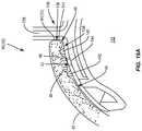
- FIG. 4is a side view of an exemplary eyelid illustrating the meibomian glands and the keratinized area of the eyelid where it was discovered that sebum produced by the meibomian gland is discharged to the keratinized lid margin in the Line of Marx area rather than directly onto the ocular tear film;
- FIG. 5is a close-up picture of the eye and lower eyelid margin illustrating a 0.1 microliter micro drop of unpreserved 2% liquid fluorescein placed on the keratinized lower eyelid margin to determine if the micro drop was altered during blinking;
- FIGS. 6A and 6Billustrate use of the Meibomian Gland EvaluatorTM to assess the meibomian gland expression of the meibomian glands of a patient's lower eyelid during an experiment to determine if keratinized upper and lower lid margins make contact;
- FIG. 7is a table illustrating the Line of Marx relative to meibomian gland orifices of patients involved in the experiment in FIGS. 6A and 6B ;
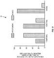
- FIG. 8is a chart illustrating exemplary mean numbers of meibomian glands in a patient's eyelid yielding liquid secretion in each segment of the lower eyelid;
- FIG. 9is a chart illustrating exemplary frequency (in percentage) of the position of the Line of Marx in a patient's lower eyelid relative to the number of meibomian gland orifices;
- FIG. 10illustrates the Line of Marx virtual line at the meeting of the wet tissue area and dry tissue area of a lower eyelid, serving to divide the wet tissue area and the dry tissue area;
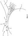
- FIG. 11is another illustration of the Line of Marx in the lower eyelid of FIG. 10 with a tip disposed behind the lower eyelid and thumb;
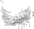
- FIG. 12Aillustrates a vertical cross section of the eye including the upper eyelid and the lower eyelid illustrating build up of devitalized and/or dead tissue in the Line of Marx area that can prevent, reduce, or affect lipids secreted from the meibomian glands from being transported to the tear film;
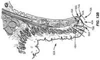
- FIG. 12Billustrates a close-up vertical cross section view of the upper eyelid in FIG. 12A , illustrating the build up of devitalized and/or dead tissue on the lid margin in the Line of Marx area that can prevent, reduce, or affect lipids secreted from the meibomian glands from being transported to the tear film;
- FIG. 13is a flowchart illustrating an exemplary process of diagnosing of devitalized and/or dead tissue in the lid margin, including in the Line of Marx area, and the treating and evaluating treatment of devitalized and/or dead tissue in the lid margin in the Line of Marx to improve transport of meibomian gland lipid secretion to the tear film to treat evaporative dry eye;
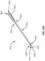
- FIG. 14Ais an exemplary treatment device configured to remove devitalized and/or dead tissue in the lid margin in the form of a “golf club” shaped spud;
- FIG. 14Bis a close up of the treatment area of the exemplary device shown in FIG. 14A ;
- FIG. 15Ais an exemplary angulation surface treatment device configured to remove devitalized and/or dead tissue in the lid margin;
- FIG. 15Bis an exemplary hook mechanical treatment device configured to remove devitalized and/or dead tissue in the lid margin
- FIG. 15Cis an exemplary cup scraper mechanical treatment device configured to remove devitalized and/or dead tissue in the lid margin;
- FIG. 16is another exemplary mechanical treatment device that has an actuator to adjust the angle of a sharp edge or a textured mechanical surface configured to remove devitalized and/or dead tissue in the lid margin;
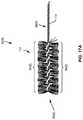
- FIG. 17Ais an exemplary deburring brush that includes an abrasive brush surface configured to be controlled by a treatment device to remove devitalized and/or dead tissue in the lid margin;
- FIG. 17Bis an exemplary deburring device that includes an abrasive brush surface configured to be controlled by a treatment device to remove devitalized and/or dead tissue in the lid margin;
- FIGS. 18A-18Dillustrate exemplary hollow distal tips that include sharp circular edges sharpened and/or textured mechanical surfaces to remove devitalized and/or dead tissue in the lid margin that can be aspirated through a hollow chamber in the distal tip as part of a mechanical treatment device;
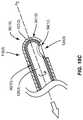
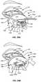
- FIG. 19Aillustrates an embodiment of an eyecup configured to provide thermal zones to the lid margins to soften devitalized and/or dead tissue before removal, wherein the thermal zones may also include optional textured mechanical surface zones to remove the softened devitalized and/or dead tissue;
- FIG. 19Billustrates an embodiment of an eye cup where the optional textured mechanical surface zone is provided on the shaft portion of the device
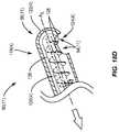
- FIG. 19Cillustrates an embodiment of an eye cup where the optional textured mechanical surface zone is specifically configured as an angled or concave surface
- FIG. 20Aillustrates another embodiment of an eyecup configured to provide thermal and textured mechanical surface zones to apply heat and force to the lid margins to soften and remove devitalized and/or dead tissue.
- the textured mechanical surface zoneis activated by the expansion of bladders within the textured mechanical surface zones;
- FIG. 20Billustrates another embodiment of an expandable bladder within the textured mechanical surface zone whereby the expandable bladder is located on the shaft;
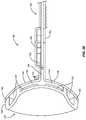
- FIG. 21illustrates a side view of an eye cup with scored lines that are placed parallel to the surface contour of the eye cup
- FIG. 22illustrates an end on view of an eye cup with ramped ridges that provide uni-directional tissue removal forces
- FIG. 23illustrates a cross sectional view of an eye cup with posts for the placement of inserts with roughened surfaces. These inserts, adhesive strips, or plates can be positioned prior to treatment;
- FIG. 24illustrates a cross sectional view of an eye cup, eye lids, and bladders with an electrical connection to a LipiFlow® generator (not shown) that provides an electrical signal for the creation of the textured mechanical surface zone during a LipiFlow® treatment;
- FIG. 25illustrates a heat and force application device according to one embodiment relating to the present invention to facilitate the application of heat to the inside and force to the outside of a patient's eyelid relating to treating meibomian glands;
- FIG. 26illustrates a lid warmer component of the heat and force application device illustrated in FIG. 25 , which is adapted to fit onto a patient's eye to controllably deliver heat to the inside of the patient's eyelid, according to one embodiment relating to the present invention
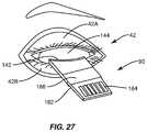
- FIG. 27illustrates the process of placing the lid warmer on the patient's eye inside the eyelid to install the heat application device onto a patient's eye for treating the meibomian glands, according to one embodiment relating to the present invention
- FIG. 28illustrates a cross-sectional view of the lid warmer illustrated in FIG. 26 to further illustrate heat delivery components and features of the lid warmer, according to one embodiment relating to the present invention
- FIGS. 29A and 29Billustrate embodiments of a lid warmer and eyecup heat and force application device for securing the eyecup to the lid warmer as part of installing the force application device onto a patient's eye for treating the meibomian glands;
- FIG. 30illustrates an interface adapted to be attached between the eyecup and the controller of FIGS. 9-13B for facilitating selective and controllable communication of heat and/or force to the eyelid, according to one embodiment of the present invention
- FIG. 31illustrates a top level system diagram of the temperature and pressure control and communication components of the heat and force application device for selectively and controllably communicating to the lid warmer and eyecup components to apply heat to the inside of a patient's eyelid and/or force to the outside of the patient's eyelid, according to one embodiment relating to the present invention
- FIG. 32illustrates an interface circuit diagram for the heating and force application device, according to one embodiment relating to the present invention
- FIG. 33illustrates a pressure control system for the heating and force application device to selectively and controllably apply force to the outside of a patient's eyelid, according to one embodiment relating to the present invention
- FIG. 34illustrates a temperature control system for the heating and force application device to selectively and controllably apply heat to the inside of a patient's eyelid, according to one embodiment relating to the present invention
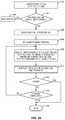
- FIG. 35is a flowchart illustrating the basic process employed by the heat and force application device to selectively and controllably apply heat to the inside of a patient's eyelid and/or force to the outside of the patient's eyelid, according to one embodiment relating to the present invention
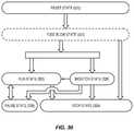
- FIG. 36illustrates a system state flow diagram for the heating and force application device, according to one embodiment relating to the present invention
- FIGS. 37A and 37Billustrate the “Reset” state flow diagram according to the system state flow diagram of FIG. 36 , according to one embodiment relating to the present invention
- FIG. 38illustrates the optional “Fuseblow” state flow diagram according to the system state flow diagram of FIG. 36 , according to one embodiment relating to the present invention
- FIG. 39illustrates the “Run” state flow diagram according to the system state flow diagram of FIG. 36 , according to one embodiment relating to the present invention
- FIG. 40illustrates the “Pause” state flow diagram according to the system state flow diagram of FIG. 36 , according to one embodiment relating to the present invention
- FIGS. 41A and 41Billustrate the “Monitor” state flow diagram according to the system state flow diagram of FIG. 36 , according to one embodiment relating to the present invention.
- FIG. 42illustrates the “Stop” state flow diagram according to the system state flow diagram of FIG. 36 , according to one embodiment relating to the present invention.
- Embodiments disclosed hereininclude apparatuses and methods for diagnosing and/or treating lipid transport deficiency in ocular tear films, and related components and devices.
- the lipid secreted by the meibomian glands being transported to the ocular tear filmis important to prevent or reduce evaporative dry eye.
- meibomian gland secretionscan be physically expressed so that the meibomian gland secretion is disposed on the keratinized area of the lid margin, but the meibomian gland secretion may not be transported to the ocular tear film.
- the Line of Marxis a virtual line at the meeting of the wet tissue area and dry tissue area of the upper and lower eyelids at the lid margin serving to divide the wet tissue areas and dry tissue areas.
- the Line of Marxis also known as the mucocutaneous junction. Marx made the observation in “Übervitale Anlagenrbungen am Auge and an den Lidern” 8 that the tissue behind the Line of Marx—the wet tissue at the lid margin, was higher than the dry tissue in front of the Line of Marx. In other words, the wet tissue at the lid margin was microscopically elevated.
- the present disclosurediscovered something that was not recognized by Marx.
- the present disclosurediscovered that devitalized and/or dead cells formed at the Line of Marx in certain patients may prevent lipid secreted by the meibomian glands from being transported to the ocular tear film thus contributing to evaporative dry eye.
- the devitalized and/or dead cells formed on the lid marginincluding at the Line of Marx and on keratinized cells and aberrant mucosal tissue, are removed according to the apparatuses and methods disclosed herein, meibomian gland secretions will not be prevented from being transported to the ocular tear film in certain patients where otherwise, the devitalized and/or dead cells formed at the Line of Marx may be sufficiently built up to prevent or reduce transport of meibomian gland secretions to the ocular tear film.
- the lipid layer 20provides a protective coating over the aqueous layer 16 to limit the rate at which the aqueous layer 16 evaporates.
- a higher rate of evaporation of the aqueous layer 16can cause dryness of the eye.
- the lipid layer 20is not sufficient to limit the rate of evaporation of the aqueous layer 16 , dryness of the eye may result.
- Substantial studieswere undertaken leading to the present disclosure on exactly how meibomian glands functioned. It was discovered during this research and studies that lipids produced by the meibomian glands are discharged onto the keratinized areas of the upper and lower eyelid margin rather than being discharged directly onto the ocular tear film itself.
- FIG. 4illustrates a side view of an eyelid 28 in FIG. 4 .
- the lipid produced by the meibomian glands 30was discharged onto the keratinized area 32 of the eyelid 28 rather than being discharged directly onto the ocular tear film itself.
- FIG. 4illustrates the meibomian glands 30 disposed inside the eyelid 28 between the inner surface of the eyelid 34 and the outer surface of the eyelid 36 .
- an approximate 0.1-microliter (100 nm in size) micro drop 38 of unpreserved 2% liquid fluorescein (B&L, Chauvin, France)was placed in the temporal (T) third of the keratinized lower lid margin 40 of the patient's lower eyelid 42 , as illustrated in FIG. 5 .
- This technique of placing the micro drop 38 in an area 44 in keratinized lid margin 40 of the lower eyelid 42allowed study of how the micro drop 38 moved on the lower eyelid 42 with blinking actions.
- diagnostic meibomian gland expressionwas performed along the lower lid margin 40 of the patient's eye 12 to assess MG functionality using a meibomian gland evaluator or Korb MGETM 52 manufactured by TearScience, Inc.
- the position of meibomian gland orifices 48 (shown in FIG. 6A ) relative to the Line of Marxis shown in the table 54 in FIG. 7 , which also shows the break down by lid position (temporal, central, or nasal).
- the nasal and central lid regionsshowed a significantly higher likelihood of the Line of Marx being posterior to the meibomian gland orifices 48 (90% and 70% of the time, respectively) relative to the temporal region (30% of the time).
- the mean numbers of meibomian glands 46 yielding liquid secretion (MGYLS) in each segment of the lower eyelid 42is illustrated in the graph 60 in FIG. 8 . There were significantly fewer MGYLS in the temporal region compared with the central (p ⁇ 0.005) and the nasal region (p ⁇ 0.0005). The mean total number of MGYLS across all lower eyelids 42 was 9.5 ⁇ 4.1.
- FIG. 9is a chart 62 illustrating frequency in percentage of the position of the Line of Marx in a patient's lower eyelid 42 relative to the number of meibomian gland orifices 48 .
- the temporal regionshowed a significantly higher likelihood of the Line of Marx undulating (touching, bisecting the meibomian gland orifices 48 , or even moving anterior to the meibomian gland orifices 48 ).
- Other experimentsinvolved placing micro drops of lissamine green and rose bengal, or preferably using fluorescein for the devitalized cells or traumatized cells and rose bengal or lissamine green for the deceased cells.
- the lipid secretion from the meibomian glands 46 delivered through the meibomian gland orifices 48 to the keratinized lid margin 40would not absorb the lipid through the keratin. Rather, the surface of the keratinized lid margin 40 would hinder the spread or act as a barrier to the dispersion of the lipid.
- the lipid secreted by the meibomian glands 46would lay in the keratinized lid margin 40 in a film with a portion being transferred to the ocular tear film. As discussed above, the lipid being transported to the ocular tear film is important to prevent or reduce evaporative dry eye.
- the Line of Marx 64is a virtual line at the meeting of the wet tissue area 66 and dry tissue area 68 of the upper and lower eyelids 42 (lower eyelid 42 shown in FIG. 10 ) at the keratinized lid margin 40 , serving to divide the wet tissue areas 66 and dry tissue areas 68 .
- FIG. 10the Line of Marx 64 is a virtual line at the meeting of the wet tissue area 66 and dry tissue area 68 of the upper and lower eyelids 42 (lower eyelid 42 shown in FIG. 10 ) at the keratinized lid margin 40 , serving to divide the wet tissue areas 66 and dry tissue areas 68 .
- FIG. 11illustrates the Line of Marx 64 with a tip 70 disposed behind the lower eyelid 42 and thumb 72 .
- the Line of Marxis also known as the mucocutaneous junction.
- Marxmade the observation that the tissue behind the Line of Marx—the wet tissue 66 at the keratinized lid margin 40 , was higher than the dry tissue 68 in front of the Line of Marx 64 .
- the wet tissue 66 at lid margin 40was microscopically elevated due to build up of devitalized and/or dead cells that form and build up at the mucocutaneous junction at the lid margin 40 .
- FIG. 12Aillustrates a vertical cross section of the eye 50 including the upper eyelid 42 A and the lower eyelid 42 B.
- FIG. 12Billustrates a close-up vertical cross section view of the upper eyelid 42 A in FIG. 12A .
- devitalized and/or dead tissue cells 76 A, 76 Bhave built up on the keratinized lid margins 40 A, 40 B.
- devitalized and/or dead tissue cells 76 A on the keratinized lid margin 40 A of the upper eyelid 42 A in the Line of Marx 64 Ais illustrated in close-up view in FIG. 12B . Note that the devitalized and/or dead tissue cells 76 A are built up higher on the wet tissue 66 A side of the keratinized lid margin 40 A at a tissue shoulder 74 A than on the dry tissue 68 A side of the keratinized lid margin 40 A in the Line of Marx 64 A.
- lipid secreted from the meibomian glands 46 A through the meibomian gland orifices 48 Ahave to pass over the devitalized and/or dead tissue cells 76 A and over the tissue shoulder 74 A to reach the tear film. If a patient's meibomian glands 46 do not provide sufficient lipid to pass over the tissue shoulder 74 A of the devitalized and/or dead tissue cells 76 A, the lipid may not reach the patients tear film, thus contributing to evaporative dry eye.
- the cell structure of the devitalized and/or dead tissue cells 76 Amay require use of over four hundred (400) to five hundred (500) magnification, and even up to one thousand (1000) magnification to be observed.
- the Line of Marx 64was found to be approximately 0.1 mm wide with healthy young individuals, and increases in width with older individuals. There can be a number of reasons why the devitalized and/or dead cells 76 form and build up at the mucocutaneous junction (Line of Marx) at the eyelid margin 40 . It is theorized that most people are partial blinkers, a condition aggravated by computer use and other activities that inhibit blinking, and the lid margins simply do not get wiped. Also, dry eye states may inhibit blinking or result in partial blinking, since the blinking actions without adequate lubrication may cause sensation resulting in inhibition of blinking. When the lid margins 40 do not get wiped and cleaned adequately by blinking action, material accumulates. This material that accumulates on the lid margins 40 may be only dead cells which are moved from the wet tissue 66 areas and the dry tissue areas 68 of the lid margin 40 to the area of the Line of Marx 64 by flow patterns or other mechanisms.
- the devitalized and/or dead cells 76are not removed, and as a result they accumulate and form on both the lower and upper lid margins 40 A, 40 B, including at the Line of Marx 64 A, 64 B and on keratinized cells and aberrant mucosal tissue, and to a greater degree on the lower lid margin 40 B.
- the resultis multifactorial.
- the deformation of the lid margins 40may alter the relationship of the upper and lower lids 42 A, 42 B during blinking, thus altering the movement of the meibomian lipid secretion from the keratinized lid margin 40 to the tear film.
- the increased material 76literally acts as a wall and barrier on the lid margin 40 to prevent the secretion from moving in to the tear film or being moved to the upper lid 42 A for delivery to the tear film.
- the embodiments disclosed hereininvolve the diagnosis and removal of the devitalized and/or dead cell material 76 formed in the lid margin 40 to attempt to restore a normal lid margin 40 .
- the devitalized and/or dead cell material 76will not prevent or reduce the transport of lipid secreted by the meibomian glands 46 to the tear film. Evaporative dry eye conditions in patients may improve as a result.
- the diagnosis and removal of devitalized and/or dead cell material 76may be performed at desired intervals, for example every six (6) months.
- Patients who suffer from conditions that block meibomian gland orifices, partial, infrequent, or inhibited blinking resulting in reduced lipid secretions from meibomian glands 46 , and/or blockages in meibomian gland channels reducing secretion of lipids through the meibomian gland orifices 48may require more frequent diagnosis and treatment to remove devitalized and/or dead cell material 76 .
- staining procedurescan be utilized to identify devitalized and/or dead cells 76 in the lid margin 40 .
- the stain fluoresceinis conceded to stain damaged cells 76 where the cell membrane has been damaged or to stain areas between the cells 76 , or the “intercellular spaces.”
- the stain rose bengal, and lissamine green, which is thought to be similar to rose bengal,are other known stains that can be used to stain devitalized cells or completely dead cells 76 .
- the patientcan be treated (block 84 in FIG. 13 ).
- the devitalized and/or dead tissue cells 76 in the lid margin 40can be removed with any number of procedures and devices, examples of which are described below.
- the goal with the removal treatmentis to “smooth” the surface at the Line of Marx 64 .
- a manual processmay be employed to remove devitalized and/or dead tissue cells 76 formed on the lid margin 40 , including at the Line of Marx 64 and on keratinized cells and aberrant mucosal tissue.
- a swab-type deviceincluding foam or sponge-tipped devices, may be rubbed over the lid margin 40 and the meibomian gland orifices 48 .
- a device with a sharp surface or blademay be used to apply a scraping motion to the devitalized and/or dead tissue cells 76 to remove the devitalized and/or dead tissue cells 76 from the lid margin 40 .
- the devitalized and/or dead tissue cells 76 formed on the lid margin 40may be heated to loosen devitalized and/or dead tissue cells 76 before and during removal.
- the devitalized and/or dead tissue cells 76may be heated to 42.5 degrees Celsius.
- This removalmay be effective in preventing the described anatomical changes and difficulties by preventing accumulation of devitalized and/or dead tissue cells 76 in the lid margin 40 .
- the rubbing of the devitalized and/or dead tissue cells 76may be provided by manual movement of 1 or 2 millimeters (mm) as a non-limiting example. It is necessary to move a sharp edge or some sharpened and/or textured mechanical surface over the cells either back and forth or within a particular direction to effect a scraping action.
- the mechanical surfacemay include a sharpened edge, or a textured or other surface.
- a textured surfaceexamples include, but are not limited to, a roughened surface, a matte finish, one or more sharpened edges, one or more raised areas, or other regular or irregular surface variations. However, it should be noted that this treatment alone may not be adequate to rectify more significant abnormalities in the lid margin 40 .
- the devitalized and/or dead tissue cells 76 in the lid margin 40 in the Line of Marx 64may be removed (block 86 in FIG. 13 ).
- the method of treatmentmay comprise only the step of removing the devitalized and/or dead tissue cells 76 in the lid margin 40 (block 86 ), with the other steps being optional.
- a mechanical treatment devicesuch as the mechanical treatment devices described below with regard to FIGS. 14-42 , having at least one sharpened and/or textured mechanical surface may be provided.
- the mechanical treatment devicesmay be used to remove the devitalized and/or dead tissue cells 76 in the lid margin 40 , as in block 86 of FIG. 13 , for example, by moving one of the at least one textured surface and a lid margin of an eyelid proximate to the Line of Marx of the eyelid against the other to exfoliate devitalized and/or dead cell material from the lid margin.
- One treatment evaluationis by the subjective response of the patient by a technician employing a sham treatment.
- the sham treatmentmay involve applying a force to the area of the eye lashes of the eyelid where function would not be impacted, but the patient would think both eyes were treated. The patient can then provide feedback as to the efficacy of the treatment.
- lid margin 40Another evaluation of treatment technique is by objective evaluation of the lid margin 40 .
- these areasmay still show some staining. Staining, as previously explained, by its very nature, only stains cells that are altered whenever devitalized and/or dead tissue cells 76 are scraped. Thus, these altered stained devitalized and/or dead tissue cells 76 are part of, and are attached to, the lid margin 40 and may or may not have deeper normal cells underneath them. After completing debridement of the altered devitalized and/or dead tissue cells 76 , these areas may still show some staining. Normal cells do not stain. If one were to then restain the lid margin 40 (block 86 in FIG.
- a mechanical treatment device 90 ( 1 )is an instrument provided in the form of a “golf club” shaped spud, as illustrated in FIGS. 14A and 14B .
- the mechanical treatment device 90 ( 1 )includes a handle 92 ( 1 ) configured to be gripped by a technician to maneuver a sharp edge or a textured mechanical surface 94 ( 1 ) in this embodiment (e.g., a sharpened edge, or textured or other surface) located at a distal end 96 ( 1 ) of a neck portion 98 ( 1 ).
- the handle 92 ( 1 )may be provided with an outer surface formed by surfaces (polygonal shaped from a cross section view) configured to be grasped similar to a pencil.
- the neck portion 98 ( 1 )is attached to the handle 92 ( 1 ) at a proximal end 100 ( 1 ) of the neck portion 98 ( 1 ).
- a techniciancan maneuver the sharpened and/or textured mechanical surface 94 ( 1 ) on devitalized and/or dead tissue cells 76 formed on the lid margin 40 to remove the devitalized and/or dead tissue cells 76 (not shown).
- the mechanical surface 94 ( 1 )may have corrugations, sharp points, or a sandpaper like surface as non-limiting examples. It may be desired that the mechanical surface 94 ( 1 ) include radii at the periphery of the surface with no sharp corners or edges to avoid the mechanical surface 94 ( 1 ) digging into or gouging tissue.
- the angled mechanical surface on 94 ( 1 ) that is effective in removing devitalized and/or dead cellsmimics in appearance the distal region indicated by angulation 102 ( 1 ) and distal end 96 ( 1 ) on FIG. 14A .
- angulation 102 ( 1 )is considered the “toe” of the angled mechanical surface and distal end 96 ( 1 ) is considered the “heel” of the mechanical surface.
- the distal surface between angulation 102 ( 1 ) and distal end 96 ( 1 )is applied to the tissue at the lid margin and is used in a scraping motion to provide debridement.
- the neck portion 98 ( 1 )may have a certain angulation 102 ( 1 ) located at the distal end 96 ( 1 ) of the neck portion 98 ( 1 ) to dispose the mechanical surface 94 ( 1 ) at an angle with respect to longitudinal axis A 1 of the handle 92 ( 1 ) or the central axis of the handle 92 ( 1 ). This may improve the ability of a technician to reach or contact devitalized and/or dead tissue cells 76 formed on the lid margin 40 for removal.
- the “toe” and “heel” of the angled textured surfaceare rounded to avoid gouging into tissue and preferably, the “toe” is rounded to present a smooth bulbous profile to reduce potential damage to the eye in the event of inadvertent contact with the eye.
- the devitalized and/or dead tissue cells 76attach to the mechanical surface 94 ( 1 ) where they can be wiped off (e.g., between 2 and 5 times during the cleaning of the approximate 30 mm wide lid margin). With very severe cases of build up of devitalized and/or dead tissue cells 76 in the lid margin 40 , the mechanical surface 94 ( 1 ) may need to be cleaned for every 2 to 3 mm of scraping.
- the mechanical treatment device 90 ( 2 ) in FIG. 15Amay be employed.
- the mechanical treatment device 90 ( 2 )may include curette-type devices 104 ( 1 ), 104 ( 2 ) disposed on each end of a handle 92 ( 2 ).
- Other elements having similar functions to the elements in the mechanical treatment device 90 ( 1 ) in FIG. 14Ashare common element numbers, but signified with ‘(2)’, and thus will not be re-described.
- FIG. 15Billustrates another exemplary mechanical treatment device 90 ( 3 ) that includes hook portions 106 ( 1 ), 106 ( 2 ) disposed at distal ends 96 ( 3 ) of neck portions 98 ( 3 ), wherein the hook portions 106 ( 1 ), 106 ( 2 ) include sharpened and/or textured mechanical surfaces 94 ( 3 ) that can be used to remove devitalized and/or dead tissue cells 76 formed on the lid margin 40 .
- FIG. 15Cillustrates another exemplary mechanical treatment device 90 ( 4 ) that includes cup scrapers 108 ( 1 ), 108 ( 2 ) disposed at distal ends 96 ( 4 ) of neck portions 98 ( 4 ), wherein the cup scrapers 108 ( 1 ), 108 ( 2 ) include sharpened and/or textured mechanical surfaces 94 ( 4 ) that can be used to remove devitalized and/or dead tissue cells 76 formed on the lid margin 40 .
- a mechanical treatment devicemay be beneficial to minimize the size of the distal end of a mechanical treatment device. It may be preferable that mechanical dislodging surfaces come provided at a ninety (90) degree angle to the neck (or at the side) to improve visibility of the cell dislodging process. Another embodiment would have the distal end of a mechanical treatment device made from optically clear or translucent material so that observation of the cell removal process could be enhanced.
- FIG. 16illustrates another mechanical treatment device 90 ( 5 ) where the angulation 102 ( 5 ) of a sharpened and/or textured mechanical surface 94 ( 5 ) at the distal end 96 ( 5 ) of a handle 92 ( 5 ) can be manually adjusted by the practitioner through an actuator 110 positioned on the handle 92 ( 5 ).
- the actuator 110may be a button or a knob, as examples.
- the actuator 110can be manipulated the by practitioner on the handle 92 ( 5 ) by depressing, sliding, or rotating the actuator 110 .
- the actuator 110readjusts the angle of contact or rotation of the neck portion 98 ( 5 ) of the mechanical treatment device 90 ( 5 ) to adjust the angle and/or rotate the mechanical surface 94 ( 5 ) during treatment.
- angulation 102 and the neck portion 98 of a mechanical treatment devicemay be desirable to provide the following additional features for angulation 102 and the neck portion 98 of a mechanical treatment device to further improve the ability to dislodge devitalized and/or dead tissue cells 76 formed on the lid margin 40 .
- the neck portion 98 and angulation 102are each malleable (or just one of these portions of the device) and may be re-formed by the practitioner to provide the best angle of reach to the eye.
- the neck portion 98 flexibleso that the amount of force being applied to the eyelid is reduced.
- the handle 92be adapted to fit in the hand with finger grips or rest against the palm of the hand.
- the mechanical treatment devices 90 for this procedureenable a one-handed procedure.
- FIG. 17Aillustrates a deburring brush 112 that includes an abrasive brush surface 94 ( 6 ).
- the deburring brush 112includes a shaft 114 that can either be part of the neck portion 98 ( 6 ) or be coupled to the neck portion 98 of a mechanical treatment device 90 .
- the deburring brush 112can be controlled to be rotated or slid, rocked, and/or vibrated, to be applied to cells of interest.
- the 17Billustrates a deburring device 116 that includes textured mechanical surfaces 94 ( 7 ).
- the deburring device 116includes a shaft 117 that can either be part of the neck portion 98 ( 7 ) or be coupled to the neck portion 98 of a mechanical treatment device 90 .
- the deburring device 116can be controlled to be slid, rocked, ultrasonically activated, and/or vibrated, to be applied to cells of interest.
- Mechanical treatment devicescan include driving force components to either move or aid in the movement of sharpened and/or textured mechanical surface 94 .
- Non-limiting examplesinclude DC powered motors, AC powered motors, and forced air driven tools, ultrasonically driven tools (or vibrational energy). Examples of these and other types of components are described in detail in U.S. Pat. No. 7,981,146.
- Manual manipulationscan also be employed by the practitioner on the handle 92 that actuate the mechanical surface 94 at the distal end 96 of the mechanical treatment device 90 (e.g., squeezing, rotating or depressing an actuator that moves, slides, rocks, ultrasonically activates, or vibrates the distal end 96 of the mechanical treatment device 90 ). All of these driving forces referenced above can be used to axially move, rotate, rock, ultrasonically activate, or vibrate a mechanical surface 94 at the eyelid. These mechanical surfaces 94 can be configured to selectively or non-selectively dislodge or remove the cells of interest from devitalized and/or dead tissue cells 76 formed on the lid margin 40 .
- the distal tip of a treatment devicecan have a sharp or mechanical feature that can be driven, as described above.
- aspiration meanscan be provided in the device to remove the dislodged cells from the field of view.
- FIG. 18AOne such embodiment is shown in cross-section in FIG. 18A .
- a tip 118 ( 1 )is shown that can be disposed at the distal end 96 of a neck portion 98 of a mechanical treatment device 90 .
- the distal end 96 ( 8 ) of the tip 118 ( 1 )includes a hollow chamber 120 ( 1 ) so that the dislodged cells can be removed by an aspiration means 122 connected to the tip 118 ( 1 ) and to the hollow chamber 120 ( 1 ).
- the aspiration means 122can be provided by a pump, wall suction (supplied by the hospital or facility), or a manual negative pressure system.
- the aspiration means 122can be controlled by a button on the handle, an exhaust hole that can be closed by the practitioner (by closing the hole with a finger tip as an example, vacuum is applied, by leaving the hole open no vacuum is supplied), by foot pedal, or other actuation.
- the distal end 96 ( 8 ) of the tip 118 ( 1 )can include a rounded outer surface 122 ( 1 ) with a concave side hole 124 ( 1 ) for selectively or non-selectively removing the dislodged cells from the field of view.
- the sharpened and/or textured mechanical surfaces 94 ( 8 ) at the concave side hole 124 ( 1 )can be moved, slid, rocked, or vibrated by one of the driving forces described earlier.
- the mechanical surfaces 94 ( 8 ) of the entire concave side hole 124 ( 1 )can be used for tissue and cell removal or selected areas or quadrants of the concave side hole 124 ( 1 ).
- the distal end 96 ( 8 )could also have a hole for applying the mechanical surface 94 ( 8 ) at the very distal end 96 ( 8 ) itself, or be provided with multiple side holes for removing the cells in which a diametrically opposite side hole can be rotated into use if the first side hole becomes clogged with cellular material.
- the side holescan be located in a number of positions on the distal end 96 ( 8 ), including the very distal end or being a distal end hole.
- an additional lumencould be provided along the hollow distal end 96 ( 8 ) for supplying saline or other fluid if it is desirable to clear the field of view by applying irrigation fluid. Alternatively only an irrigation means may be employed.
- the lumencan be used to supply mineral oil or other unbinding agent.
- FIG. 18Bshows an alternative tip 118 ( 2 ) with a hollow distal end 96 ( 9 ).
- the instrumenthas a rounded distal end 96 ( 9 ), with a convex side hole 124 ( 2 ) that has mechanical surfaces 94 ( 9 ) that emanate from the periphery of the side hole 124 ( 2 ).
- the aspiration means 122can be supplied to remove the cells as they accumulate upon the mechanical surfaces 94 ( 9 ).
- the convex side hole 124 ( 2 )can provide greater mechanical advantage and accessibility for the physician in reaching the target tissue and cells.
- the hollow distal end 96can come with an interior piece that performs the mechanical action of removing the cells.
- a tip 118 ( 3 )that can be provided as part of a mechanical treatment device 90 ( 10 ) is shown in FIG. 18C .
- the tip 118 ( 3 )is provided within the hollow distal end 96 ( 10 ).
- the tip 118 ( 3 )is configured to be rotated about the central axis A 2 of the mechanical treatment device 90 ( 10 ) in which a mechanical surface 94 ( 10 ) is exposed and dislodges the cells within or adjacent to a side hole 124 ( 3 ).
- the rotation of the tip 118 ( 3 )can also be vibrational, translational (slid), or rocked (slight rotations about the central axis).
- DC motors, AC motors, forced air, ultrasonically, or manually driven componentscan also be provided as part of the mechanical treatment device 90 ( 10 ) to move the mechanical surface 94 ( 10 ).
- the tip 118 ( 3 )is hollow and the aspiration means 122 is applied through a hollow chamber 120 ( 3 ).
- the aspiration means 122can also be applied through the hollow distal end 96 ( 10 ), as described above.
- the mechanical surface 94 ( 10 )can be composed of irregular surface features, sandpaper, sharp edge(s), or bristles as described previously.
- the mechanical surface 94 ( 10 )has a concave appearance.
- the mechanical surfacecan protrude in a convex configuration to more easily affect the cells or tissue of interest in a similar fashion as a side hole 124 ( 3 ) can be convex or concave, as discussed above in FIGS. 18A and 18B .
- FIG. 18Dshows another embodiment of a tip 118 ( 4 ) that can be employed with a mechanical treatment device 90 ( 11 ).
- the tip 118 ( 4 )does not require a separate aspiration means although aspiration (as well as irrigation through a second lumen) can be performed with this tip 118 ( 4 ), if necessary.
- the hollow distal end 96 ( 11 ) of the tip 118 ( 4 )contains an interior auger 126 that can be made by any spiral or helical pitch configuration.
- the auger 126can provide a mechanical dislodging surface 128 that can act as a mechanical surface 94 ( 11 ) exposed at a side hole 124 ( 4 ) of the tip 118 ( 4 ).
- the mechanical dislodging surface 128can include a textured or other surface, including one or more roughened or sharpened edges.
- the auger 126is rotated about the central axis A 3 of the mechanical treatment device 90 ( 11 ). By controlling the pitch of the auger 126 , the direction of rotation, and the speed of rotation, the cellular material that is being dislodged can be directed back through the hollow distal end 124 ( 4 ) in a proximal direction and removed from the field of view.
- the mechanical dislodging surface 128may be pitched and/or textured such that the mechanical dislodging surface 128 scrapes against the lid margin when the lid margin is moved against the textured surface in a first direction, and slides against the lid margin when the lid margin is moved against the mechanical dislodging surface 128 in the opposite direction.
- Treatment devicesmay also be employed that apply heat to the keratinized tissue of the lid margin 40 that can result in a denaturing of binding mechanisms in the devitalized and/or dead tissue cells 76 .
- This heat applicationmay soften the devitalized and/or dead tissue cells 76 , thus requiring less force for removal. It has been observed that a temperature of 42.5 degrees Celsius is effective in denaturing the binding mechanisms devitalized and/or dead tissue cells 76 to the keratinized cells of the lid margin 40 . However, higher and lower temperatures for varying time durations can be applied as well.
- the denaturing of these devitalized and/or dead tissue cells 76can be accomplished by heat and force.
- the eyelid margins 40can be warmed by a variety of devices and methods, examples of which are described below in more detail. A practitioner would need to provide for the patient's cornea/eye to not be affected by the heating process. In addition, the addition of mineral oil or other unbinding agent on the target tissue can be beneficial for the removal of these devitalized and/or dead tissue cells 76 .
- a thermal preconditioning eye cup 130can be provided.
- the eye cup 130can include a thermal activated surface to heat the lid margins 40 of an eyelid 42 prior to cell removal.
- the eye cup 130can be placed on the eye globe 132 to protect the eye and cornea (not shown).
- the eye cup 130can be charged by a thermal producing means 133 (not shown) to heat a thermal zone 136 . Only one eyelid 42 is shown in the diagram; however, both eye lids can be treated at the same time.
- the thermal zone 136can extend further up on a shaft 138 and more lateral to both raised areas 142 shown on the eye cup 130 .
- the eye cup 130would be placed to precondition the eyelid margins 40 prior to cell and tissue removal.
- An electronic controllerlike that provided in U.S. Pat. No. 7,981,146, entitled “Inner Eyelid Treatment for Treating Meibomian Gland Dysfunction,” which is incorporated herein by reference in its entirety, may be used to control the heat applied by the thermal zone 136 of the eye cup 130 .
- the exterior surface of the eye cup 130could have an application of mineral oil or other unbinding agent on it at the location of the lid margin 40 .
- the eye cup 130could also have a coating of mineral oil or other unbinding agent integrated onto the exterior surface of the eye cup 130 .
- a mechanical treatment device 90can supply the force to remove the devitalized and/or dead tissue cells 76 from the lid margin 40 .
- the eye cup 130could also include the treatment device 90 to remove the devitalized and/or dead tissue cells 76 from the lid margin 40 .
- just the distal end 96 of the instrument that is pre-heatedcan be placed onto a handle 92 prior to application to the eye lid margin and tissue removal.
- the distal 96 or the mechanical surfaces 94 of the treatment devices 90can be heated to an elevated temperature. Heating the distal end 96 of the treatment device 90 can be internally driven by a heating apparatus that is controlled by DC battery, AC power, or other heating means. An RF/microwave energy heating mechanism can be employed to selectively heat just the distal end 96 of the treatment device 90 or the mechanical surface 94 , such as described in P.C.T. Patent Application No. PCT/US12/44650, entitled “Methods and Systems for Treating Meibomian Gland Dysfunction Using Radio-Frequency Energy,” incorporated herein by reference in its entirety.
- the RF/microwave energy heating mechanismcan be configured to heat both the treatment device 90 and the tissue around the mechanical surface 94 .
- the RF/microwave fieldwould heat the distal end (or mechanical surface) and the nearby or adjacent tissue.
- the heating of the nearby tissuecan be accomplished by selectively heating a gel, a coating of mineral oil or other agent, or other fluid at the tissue of interest. The heating would be done at a pre-determined tissue temperature.
- the temperaturecan be controlled by a temperature sensor or controller, as described in U.S. Pat. No. 7,981,146 referenced above.
- the RF/microwave energy heatingcan be directed to only heat the tissue and not the distal end 96 of the treatment device 90 .
- the heating of the treatment device 90could also include the interior heating of the hollow distal end tips 118 previously described to allow for the easier passage of the removed cells and tissue in a heated state with aspiration means.
- the movementcan supply elevated temperature at the distal end 96 as a result of the mechanical action at the distal end 96 of the treatment device 90 .
- the elevated temperature of the distal end 96 of the treatment device 90 due to mechanical movementswould be beneficial for the removal of the cells of interest.
- the hollow distal end 96 of the tips 118 described abovecan supply heated air, CO 2 , or other gas through the hollow distal end 96 onto the tissue of interest.
- the air or gasis heated and delivered by heating and pumping sources not shown in the diagrams.
- the pumping of heated air or gascan be alternated with aspiration means 122 , depending upon an initial heating of tissue with the forced heated air or gas, followed by aspiration as tissue or cells accumulate on the mechanical surfaces.
- the switching of forced heated air or gas and aspirationcan be controlled by the physician through various types of hand piece buttons, valves, or similar controlling mechanisms.
- the hollow lumencan be used to place mineral oil or other agent for unbinding at the tissue of interest.
- the mechanical surfaces 94 that remove these cellscan be integrated onto the exterior surface of the eye cup 130 in FIG. 19A or LipiFlow® Activator described in U.S. Pat. No. 7,981,146 to provide a treatment device 90 ( 12 ).
- a treatment device 9012
- FIG. 19AOne such embodiment is illustrated in FIG. 19A .
- the processcould involve causing the thermal zones 136 to apply heat to the lid margin 40 (described in greater detail with respect to FIGS. 25-42 below), and moving the shaft 138 after 8-10 minutes of heating to cause mechanical surfaces 94 ( 12 ), which may be provided as sand paper-type surface, to be moved about the lid margin 40 .
- the eyelid 42rests of top of the eye cup 130 with shaft 138 .
- a mechanical surface 9412 forming a mechanical surface zone 144 that can be moved, slid, vibrated, or rotated through a controlling and power mechanism through connection.
- Powermeans not shown.
- the exterior portion of the eye lid 42can be contained by the LipiFlow® Activator (not shown) as described previously for the LipiFlow® procedure. What is not shown is the mechanism for moving, sliding, rotating, or vibrating the mechanical surface zone 144 .
- the mechanical surface zone 144may be configured to move independently from the rest of the eye cup 130 so that only the lid margin 40 area near the mechanical surface zone 144 would be affected. It would be the intention of the powering mechanism (not shown) to not disrupt or agitate the eye globe 132 .
- FIG. 19Bshows another configuration of the mechanical surface zone 144 .
- the mechanical surface zone 144contains ridges, roughened surface finish, or a less lubricious surface finish 138 positioned near the base of the exterior surface of shaft 138 that contacts the eye lid 42 .
- the mechanical surface zone 144can be positioned on both shaft 138 , as seen in FIG. 19B , and eye cup 130 , as seen in Figure 19 A. Additional features of the eye cup are described in greater detail below with respect to FIGS. 25-28 .
- FIG. 19Cshows another configuration of the eye cup 130 with a mechanical surface 94 ( 12 ) that is shaped to a concave or angled surface to form a more tightly fitting surface to the eyelid margin.
- the power meansis the mechanical action that occurs during a LipiFlow® treatment.
- the inflatable bladdersare inflated and deflated as part of the compressive forces of the treatment regime, the inflations create mechanical movement of the eyelids on the mechanical surfaces 94 found preferentially on concave or angled surface 94 .
- the resultant motion on the eyelidscan be sideways, rotational, or variable.
- the mechanical action of the textured surfacescan be introduced into the treatment cycle at predetermined or selected time point or multiple time durations within a treatment cycle.
- the eye lidcould be preconditioned with a heating cycle with a subsequent exposure to a textured mechanical surface at a point where the material at the Line of Marx has experienced some softening due to thermal exposure.
- the physiciancan select various degrees of exposure to a textured mechanical surface at his discretion during a treatment cycle as a response to the underlying condition of the patient. Additional discussion of the mechanics of the application of compressive force to the eyelids are described in greater detail below with respect to FIGS. 27-30 .
- the eyecup 130 of FIG. 19Ashows that the mechanical surface zone 144 can be placed on an expanding member, such as a balloon bladder 146 like described in U.S. Pat. No. 7,981,146, to provide greater engagement with the eyelid margin 40 . Greater engagement can be accomplished with direct mechanical expansion of this mechanical surface zone 144 .
- an expanding membersuch as a balloon bladder 146 like described in U.S. Pat. No. 7,981,146
- greater engagementcan be accomplished with direct mechanical expansion of this mechanical surface zone 144 .
- On the shaft 138there are thermal and mechanical surface zones 144 that work to heat the tissue of interest at the Line of Marx 64 to facilitate the removal of devitalized and/or dead cells 76 .
- the heatingcan be programmed to work at any point in the LipiFlow cycle. As an example, it can be programmed within some intermediate time point in the LipiFlow® cycle such as the 8 minute mark.
- the thermal and mechanical surface zones 144can be actuated to engage the tissue of interest. The engagement can be accomplished by radial expansion of the mechanical surfaces 94 ( 13 ). Air can be provided to expandable bladders from the LipiFlow® generator (not shown) within shaft 138 as indicated by air flow 140 . The engagement of the expandable bladders in the mechanical surface zone 94 can be enhanced by bladders 146 that provide bladder compression pressure that preferentially pushes the eyelids 42 A, 42 B towards the center shaft 138 .
- the thermal and mechanical surface zones 144can move against the tissue on eyelids 42 A, 42 B without affecting the stability or position of the eye cup protector 146 .
- This combination of tissue removalcan be done before, during, or after the LipiFlow® treatment.
- Incorporating mineral oil or other unbinding agentcan be employed on the activator as discussed previously.
- FIG. 20Bshows the LipiFlow® activator with bladders 146 , shaft 138 , and mechanical surfaces 94 for creating debridement on eyelids 42 A and 42 B on eye globe 132 .
- a base portion of the shaft 138contains an additional bladder 150 that can inflate and deflate during the LipiFlow® treatment.
- Bladder 150provides an additional mechanical action on eye lids 42 A and 42 B and movement on mechanical surfaces 94 .
- Bladder 150can be controlled to inflate and deflate independently or simultaneously with bladders 146 .
- the inflation of additional bladder 150can create greater mechanical force on the eye lids 42 A and 42 B.
- bladder 150 , and the resultant increased mechanical actioncan be timed to occur after a predetermined amount of heating has occurred with the eyelids.
- FIG. 21depicts another configuration of a mechanical treatment device 90 ( 14 ) having an eye cup 130 and a plurality of mechanical surfaces 94 ( 14 ).
- the degree of tissue removalcan be influenced by the degree of roughness on the surface finish of the LipiFlow® activator.
- the surface finish of the mechanical surfaces 94 ( 14 ) on the LipiFlow® activatorcan be created by the specific scoring of lines, grooves, or ridges 152 on the mechanical surface 94 ( 14 ) that run parallel to the eye cup 130 as seen in FIG. 21 .
- the mechanical forcescan be directed along the eye lid (not shown) which is above eye cup 130 .
- Scored lines, grooves or ridges 152can be created by running a roughened instrument in a path parallel to the curved surface of the eye cup. Additional features of the eye cup 130 and other components of mechanical treatment device 90 ( 14 ) and related devices are described in greater detail below with respect to FIGS. 25-30 .
- FIG. 22shows another configuration of a mechanical treatment device 90 ( 15 ) having an eye cup 130 in another view, to illustrate an embodiment of parallel ridges or lines 154 along eye cup 130 that provide uni-directional mechanical action.
- the ramped configuration of the ridges 154create mechanical force only in a central direction or in the direction of the eye lid opening as shown by lines 156 , that indicate the direction of tissue removal.
- Other configurations or directions for the ramped ridges in the mechanical surface 94 ( 15 )are possible, such as ridges 154 that are oriented in a direction opposite the direction of the eye lid opening.
- FIG. 23demonstrates another embodiment of a mechanical treatment device 90 ( 16 ) having an eye cup 130 that provides the physician the ability to vary the amount of mechanical action provided by mechanical surface 94 ( 16 ) on the eye lid 42 .
- the mechanical surface 94 ( 16 )can be altered or selected through the use of inserts, adhesive strips, or plates 158 that can be applied by the physician prior to treatment.
- FIG. 23illustrates posts 134 that provide positioning and placement of inserts.
- FIG. 24shows another embodiment of a mechanical treatment device 90 ( 17 ) having an eye cup 130 that has ridges and roughened surfaces electronically controlled by the LipiFlow® generator (not shown). It may be clinically beneficial to initiate the debridement action on eyelids 42 A and 42 B following a preheating or preconditioning cycle on the eye lids.
- an electronic signal or electrical power source 160 from LipiFlow® generator (not shown) through shaft 138activates surface features 162 on mechanical surface 94 ( 17 ).
- the change in surface finishcan be created through a variety of means.
- surface features that can react to electrical power or signalscan be resistive elements that expand to create raised surfaces for mechanical action, or the passage of electrical current on nitinol material can create mechanical movement or flexure in response to the electrical current. These flexures, movements, or material expansions can provide an additional sharpened and/or textured mechanical surface for the debridement of tissue on the eye lid.
- one or more raised areas or surface finishes 142can be added to existing Meibomian Gland Dysfunction (MGD) treatment devices, such as a LipiFlow® Activator described in U.S. Pat. No. 7,981,146.
- MGDMeibomian Gland Dysfunction
- a forcecan be applied to the outside of the eyelid while heat is applied to the inside of the eyelid to treat MGD.
- the heating of the inner surface of the upper or lower eyelidcan be done by any convenient method.
- the lidscan be heated one at a time or both at once, depending on the time available to remove the occlusions once heated.
- a device for treating MGDcan simultaneously remove devitalized cells from the lid margin of a patient.
- One device for heating the palpebral conjunctivais illustrated in FIGS. 25-30 .
- FIG. 25illustrates the overall device referred to as a heat and force application device 164 .
- the heat and force application device 164consists of a hand-held, battery-operated controller 166 that contains heat and pressure generating and regulation components.
- the controller 166can also be a non hand-held device that is either mounted or rests on a table top, for example.
- the controller 166 as described hereinis intended to describe and encompass any device, including but not limited to electronic and pneumatic controls and supporting components, that is adapted to allow and control the application of heat and/or force to the patient's eyelid.
- the controller 166is connected to a disposable component 90 , via a controller interface 168 , to generate heat and force at an eyelid 42 , as illustrated in FIG. 25 .
- the disposable component 90consists of a lid warmer 90 provided in the form of a lens (illustrated in FIGS. 26-28 ) that applies heat to the inside of the patent's eyelid and interfaces with an eye cup to apply force to the outside of the patient's eyelid (illustrated in FIGS. 29A, 29B, and 30 ). Both can be used in concert to treat MGD for a single eye.
- the interface 168 tubingcan be wrapped around the patient's ear 170 with any excess clipped to the patient's clothing.
- the heat and force application device 164is intended for use by physicians to apply localized heat and pressure therapy for treating MGD.
- the controller 166contains a user interface 172 to allow a physician or other technician to control the heat and force application device 164 . Temperature and pressure being applied to the patient's eyelid 42 can be seen on a temperature display 174 and a pressure display 176 . By observing temperature and pressure displays 174 , 176 , the physician can determine when a therapeutic temperature and pressure have been reached. For example, the temperature and pressure displays 174 , 176 may be segment bar graphs so that both the temperature and pressure levels and the increasing or decreasing nature of the temperature and pressure levels can be seen. The temperature level to be reached at the patient's eyelid can either be set to a static level within the controller 166 , or controllable by a physician or technician.
- the force and thus the pressure applied to the patient's eyelidis controllable by squeezing a force lever 178 .
- the force lever 178can be squeezed.
- the force lever 178is disengaged.
- the pressure created by the force applied to the patient's eyelidis displayed on the pressure display 176 .
- a timer display 180can be provided on the controller 166 to display the amount of time that heat and/or force has been applied to the patient's eyelid 42 .
- the timer display 180can display a cumulative amount of time passed or provide a countdown timer if an initial duration is set.
- the timer display 180may be comprised of a number of seven segment displays. In one embodiment, the timer display 180 will count down from one hundred eighty (180) seconds and will flash at one hundred twenty (120) seconds and sixty (60) seconds, which is an indicator to the physician to release the force lever 178 and then reapply force and pressure by squeezing the lever 178 again.
- FIG. 26illustrates the disposable component 90 in more detail.
- the disposable component 90consists of a lid warmer 90 that includes a lens in the disclosed embodiment.
- the lens 130contains a heating element to apply heat to a patient's eyelids 42 A, 42 B, but also provides an insulating back plate against which force may be applied.
- the lens 130is placed on the patient's eye with the patient's upper and lower eyelids 42 A, 42 B resting on the outside surface of the lens 144 .
- the scleral side of lens 130may be lubricated with saline, or equivalent lubricating drops (not shown).
- the lens 130is then inserted onto the patient's eye under the eyelids 42 A, 42 B.
- a heating element(not shown) is contained within the lens 130 that can apply heat to the inside of the patient's eyelid when installed.
- the material used to construct the lens 130is not electrically conductive, but is thermally conductive to allow heat from the heating element inside to be transferred to the patient's eyelid.
- the lens 130can be constructed out of a plastic, including a clear plastic such as LEXAN HPS2 for example. Further, the lens 130 can be constructed from a biocompatible material, such as polymethylmethacrylate (PMMA), epoxy, or other materials well known to those skilled in the art.
- PMMApolymethylmethacrylate
- the lens 130may be flexible, but ideally should be only minimally compressible to fit against the patient's eyeball.
- the lens 130also contains a lid warmer platform or tab 182 that is attached to the lens 130 .
- the lid warmer platform 182may be connected perpendicularly to the lens 130 such that it extends away from the patient's eye when installed.
- the lid warmer platform 182provides several benefits. First, it provides a handle for insertion and movement or adjustment of the lens 130 and its heating element. Second, it provides a guide post for a compression force device to attach to apply a force to the patient's eyelid while the lens 130 applies heat to the inside of the patient's eyelid.
- the lid warmer platform 182can also support a lens electrical interface 184 to allow the lens 130 to electrically connect the heating element inside the lens 130 to the controller 166 via the interface 168 (not shown).
- the controller 166can then apply electrical energy to the heating element to generate heat within the lens 130 and thus to the inside of the patient's eyelid when installed. It also provides a support structure for interface circuitry 98 .
- the interface circuitry 98provides electrical connections for energizing the heating element and communicating temperature measured at the lens 130 back to the controller 166 for heat regulation.
- the interface circuitry 98will discussed later in this application and in regard to FIG. 32 .
- FIG. 28illustrates a cross-sectional view of the lid warmer employing the lens 130 illustrated in FIGS. 25-27 , to further illustrate heat delivery components and features of the lid warmer in combination with raised areas 142 , similar to the raised areas 142 described above with respect to FIGS. 19A-C for removing devitalized cells from the lid margin, according to one embodiment of the present invention.
- the lens 130is formed by a scleral side 93 being attached to an eyelid side 92 .
- the scleral side 93 of the lens 130contains a bend 188 around its circumference edge to provide an attachment edge 190 to support attachment of the eyelid side 92 . Because of the bend 188 , a hollow chambers 192 are formed inside the lens 130 .
- the hollow chamber 192supports a heating element 194 contained inside the lens 130 to generate heat when energized.
- the heating element 194abuts against the eyelid side 92 of the lens 130 so that the heat generated is located adjacent the inner eyelid to apply heat to the meibomian glands.
- the heating element 194is attached to the interface circuitry 98 via a fused link 196 , which is then attached to the controller 166 via the lid warmer platform 182 being attached to the controller interface 168 (not shown). In this manner, the controller 166 can cause the heating element 194 inside the lens 130 to generate heat by applying an electrical signal to the interface circuitry 98 , which is connected to the heating element 194 .
- the link 196would melt and create an open circuit to disable the heating element 194 for safety reasons.
- the fused link 196could be a thermal link provided as an integrated part of the heating element such that the fused link 196 would melt and create an open circuit at a given threshold temperature.
- the heating element 194may be provided in any form or material.
- the heating element 194may be a resistive type heater, a thick film heater, or any one of a number of other types, such as a “flex circuit” (etched metal on flexible substrate) well known to those skilled in the art.
- the heating element 194can be formed to the shape of the lens 130 .
- the heating element 194is a material that is both electrically and thermally conductive. This may be important, as the electrical conductivity characteristic allows current to be applied to the heating element 194 to generate resistive heat.
- the thermal conductivity characteristicserves to evenly distribute the resistive heat over the entire heating element 194 and thus distributes the heat to the patient's eyelid more evenly.
- Examplesinclude the E5101 carbon-loaded polyphenylene sulfide and the E2 liquid crystal polymer, both manufactured by Cool Polymers, Inc.
- the size of the lens 130may also play a part in the heating element 194 selection and the amount of heat it must generate to be effective in MGD treatment.
- the lens 130distributes heat generated by the heating element 194 .
- a larger lens 130may distribute the heat generated by the heating element 194 more uniformly and over a larger surface area.
- the application of heat to the patient's eyeliddoes not necessarily have to include an embedded heating element 194 in the lens 130 .
- Heat applicationmay be provided as part of the environment, such as air for example. The amount of heat applied, the temperature reached at the meibomian glands as a result, where the heat is applied on the patient's eyelid or surrounding tissue, and the duration of heat applied can control the selection of the heating source.
- the lens 130may also contain an integrated insulator inside the chamber 192 as an additional measure of insulation. Insulation prevents substantial heat from reaching the eyeball and thus protects the cornea and sclera.
- the term “insulate” or “insulation”is intended to include any component or material and/or specific geometries of components or materials, wherein there is greater resistance to thermal conduction or radiation towards the surface of the eye than towards the eyelid. Stated alternatively, in the insulator, thermal energy radiates more easily towards the eyelid 42 A, 42 B than towards the eyeball surface in order to minimize the possibility of causing injury to the eyeball.
- the integrated insulatoris air and is formed by the natural gap that exists by the space left by the heating element 194 not filling up the entire volume of the chamber 192 .
- the heating element 194is biased according to its location in the lens 130 , and in particular to be located behind the integrated insulator, to produce more heat on the inside of the patient's eyelids than on their eyeball.
- FIG. 29Aillustrates an eyecup 198 that is adapted to allow the controller 166 to apply a force and/or heat to the patient's eyelids 42 A, 42 B.
- the eyecup 198is a curved carrier 206 that supports an inflatable bladder 146 .
- the inflatable bladder 146is attached to the curved carrier 206 .
- the inflatable bladder 146is then connected to the controller 166 via a tubing 208 in the controller interface 168 (see FIG. 30 ) such that the controller 166 can pump air into the tubing 208 to inflate the inflatable bladder 146 .
- the eyecup 198applies force to the outside of the eyelid 42 A, 42 B while heat can be applied via the lens 130 and heating element 194 .
- the bladder 146is inflated under control of the controller 166 .
- the air in the bladder 146is released by the controller 166 .
- the lid warmer platform 182When desired to be used, the lid warmer platform 182 is inserted into an eyecup orifice or slot 202 in the eyecup 198 between a latching mechanism 204 .
- the latching mechanism 204provides a means to secure the lid warmer platform 182 to the eyecup 198 when in use, as well as to provide an interface to electrically connect the lid warmer electrical interface 184 to the controller 166 via the controller interface 168 .
- the latching mechanism 204is comprised of a carrier 206 having a semi-circular carrier base 210 .
- the carrier base 210receives an eyecup platform 214 attached to the eyecup 198 .
- the carrier base 210 and eyecup platform 214can be squeezed together like a clip to control an opening through which the lid warmer platform 182 is inserted into the carrier 206 when inserted into the orifice 202 of the eyecup 198 .
- the carrier opening through which the lid warmer platform 182 is insertedcloses to secure the lid warmer platform 182 to the carrier 206 , and thus the eyecup 198 .
- the eyecup platform 210is adapted to allow the lid warmer platform 182 to rest on top when inserted into the eyecup orifice 202 .
- the electrical interface 184 of the lid warmer 74contacts a carrier interface 123 (not shown), which provides an electrical connection between the electrical interface 184 and the controller interface 168 .
- FIG. 29Billustrates an alternative latching mechanism 204 A to one illustrated in FIG. 29A .
- the latching mechanism 204 Ais compressed in the horizontal plane while the eyecup 198 is moved forward along the lid warmer tab 182 A until it rests against the outside of the patient's eyelids 42 A, 42 B.
- the latching mechanism 204 Ais released, the eyecup 198 is fixed in place in its location along the lid warmer tab 182 A. In this manner, the patient's eyelids 42 A, 42 B are “sandwiched” between the lens 130 and the eyecup 198 .
- FIG. 30illustrates more detail regarding the controller interface 168 .
- the controller interface 168couples the controller 166 to the lens 130 and eyecup 198 to allow the controller 166 to controllably apply heat and/or force to the patient's eyelid as part of a MGD treatment.
- the controller interface 168contains a connector 212 on one end that connects to the controller 166 .
- the connector 212includes both an electrical interface 216 and a pneumatic interface 220 .
- the electrical interface 216allows the controller 166 to send and receive electrical signals over an electronics wiring 222 to and from the lid warmer 90 , as will be described in more detail below.
- the electronics wiring 222interfaces with an eyecup electrical connector 224 on the eyecup 198 such that the lid warmer electrical interface 184 of the lid warmer 90 is connected to the electronics wiring 222 when the lid warmer platform 182 is inserted into the eyecup 198 , as illustrated in the examples of FIGS. 29A and 29B .
- the pneumatic interface 220allows the controller 166 to pump into the tubing 208 to inflate the inflatable bladder 146 on the eyecup 198 to apply force to the patient's eye and to deflate the air in the inflatable bladder 146 to release force and relieve pressure.
- the pneumatic interface 220is securely coupled to the inflatable bladder 146 on the eyecup 198 .
- FIG. 31supplements FIG. 30 to illustrate the interface components between the controller 166 and the disposable component 90 and the eyecup 198 , at a system level.
- the controller 166 of the heat and force application device 164contains a pressure control system 226 and a temperature control system 228 .
- the pressure control system 226is the control component within the controller 166 that controls the pressure from the force applied to the patient's eye via the eyecup 198 .
- the temperature control system 228is the control component within the controller 166 that controls the heat applied to the patient's eye via the lid warmer 90 .
- the pressure control system 226also communicates the pressure in the tubing 208 to a pressure sensor 230 within the pressure control system 226 .
- the pressure sensor 230is used to determine the pressure level in the tubing 208 to display the pressure on the pressure display 176 as well as to provide feedback to the controller 166 to provide the various functions and controls for the system, as will be described in more detail below.
- the pressure sensor 230also allows the recordation of pressure data to be recorded by the controller 166 , or an external data acquisition device (not shown) coupled to the controller 166 , if desired.
- FIG. 31also illustrates more detail regarding the latching mechanism 204 on the eyecup 130 .
- the latching mechanism 204facilitates providing a connection between the lid warmer 90 and the lid warmer platform 182 and the eyecup 198 , and the lid warmer 90 to the electronics wiring 222 when the eyecup orifice 202 is slipped over to the lens platform 182 to secure the eyecup 198 to the patient's eyelid.
- Two different types of latching mechanism 204 , 116 Awere previously illustrated in FIGS. 29A and 29B , either of which can be used to secure the platform 182 to the eyecup 198 , or any other type may be used.
- FIG. 32illustrates the specific wiring and supporting circuitry that comprises the electronics wiring 222 to interface the controller 166 , and particularly the temperature control system 228 , to the lid warmer 90 to apply heat to the patient's eye for the disclosed embodiment.
- Six wiresmake up the electronics wiring 222 .
- the six interface wiresare connected to the interface circuitry 98 that is embedded in the disposable component 90 .
- HEATER+ and HEATER ⁇are connected to the heating element 194 in the lid warmer 90 when the platform 182 is connected to the controller interface 168 .
- THERM1+ and THERM2+are coupled to two thermistors 232 A, 232 B.
- the two thermistors 232 A, 232 Bprovide an indication of temperature at the patient's eyelid as part of a temperature feedback mechanism to allow the temperature control system 228 to monitor the temperature for control. Because in the preferred embodiment, the temperature drop between the heating element 194 and the inside of the patient's eyelid is minimal, regulating temperature is simpler. This is because the thermistors 232 A, 232 B record temperatures closer to the actual temperatures at the glands and thus temperature overshooting is minimized. It is important to attempt to minimize temperature overshoot so as to not damage the patient's tissue. Temperature thermostats or other more complicated regulation circuits may be employed to regulate temperature as well if desired, especially if temperature overshooting is an issue. Further, the size of the heating element and power supply could also be selected so that only a known maximum amount of heat could be generated even if the heating element 194 were energized all the time. This would avoid use of a regulation circuit to prevent temperature overshoot.
- Two thermistors 232 A, 232 Bare provided for redundancy and error checking in the event one fails. Both thermistors 232 A, 232 B should provide the same signal indicative of temperature. Both thermistors are coupled to a common RETURN to provide common current return/grounding. Lastly, a FUSE line is provided and linked to a fuse 234 , which is also coupled to the RETURN line. As will be discussed later in this application, the controller 166 can send a current over the FUSE line sufficient to blow fuse 234 . The controller 166 can blow the fuse 234 to provide an indication that the lid warmer 90 has been previously used. Thus, if the lid warmer 90 is reused, the controller 166 can detect the open circuit on the FUSE line and know that the fuse 234 has been previously blown.
- FIG. 33illustrates additional components of the pressure control system 226 to provide more detail for the disclosed embodiment.
- the pressure control system 226contains an electric pump 236 to pump air into the tubing 208 .
- Other types of pumpsmay be used.
- a check valve 238is provided inline in the tubing 208 between the electric pump 236 and the inflatable bladder 146 to allow the controller 166 to draw in air to the system to use to inflate the inflatable bladder 146 without backflow release.
- a relief valve 240is also provided as a safety measure to ensure that line pressure to the eyecup 198 does not exceed maximum pressure settings in the controller 166 .
- the pressure sensor 230is coupled to the tubing 208 to communicate the pressure in the tubing 208 to the pressure control system 226 for various functions.
- FIG. 34illustrates the temperature control system 228 in more detail for the preferred embodiment.
- the temperature control system 228includes a power system 242 to provide power to the system components.
- batteries 244are used as the power supply. Energy from the batteries 244 are provided to a reverse battery protection and low battery detection circuit 246 . If the batteries 244 are low in power, a low battery signal is communicated over a low battery signal line 248 to a timer and display controller 250 D.
- the timer and display controller 250 Dis responsible for controlling therapy timers and displaying them on the timer display 180 .
- the timer and display controller 250 Dis also used to communicate other codes to the user regarding the controller 166 , including the low battery signal.
- the energy from the batteries 244is also routed to various DC-DC converters 252 to provide various voltage levels needed by the controller 166 and its components for operation. Note that the present invention is not limited to any particular type of power system or specific power components.
- the temperature control system 228may also contain a data interface 254 to provide pressure and temperature data to a data logger 256 .
- the data logger 256may also contain a timer interface 258 for the timer and display controller 250 D so that times can be recorded for the data.
- the data logger 256may be used to record data regarding patient treatments for analysis and/or to provide data for test purposes.
- the data logger 256may be coupled to a test connector 260 so that logged data regarding the system may be viewed and/or recorded via an external device (not shown) coupled to the test connector 260 .
- the remainder of the temperature control system 228consists of various components of the controller 166 that provide the overall operation and control of the heat and force application device 164 .
- These componentsare provided in the form of various circuits and control components, including programmable gate arrays (PGA).
- PGAprogrammable gate arrays
- the componentsinteract together to provide a system logic for operation of the system.
- FIGS. 37-42describe the logic control of the system. Note that these components can be provided by either analog or digital circuitry, and can be provided using a microprocessor-based architecting, including software, if desired.
- FIGS. 37A-42illustrate the state machine of the controller 166 and the various operations performed in the states that provide the operation and logic of the heat and force application device 164 .
- FIG. 35will be discussed in conjunction with the various states that make up the state machine of the controller 166 illustrated in FIG. 35 .
- FIG. 35illustrates a flowchart which describes the overall operation and logic of the heat and force application device 164 that is carried out by the controller 166 and its systems, including the pressure control system 226 and the temperature control system 228 , according to an embodiment of the present invention.
- the processstarts by the controller 166 resetting in the reset state (step 300 in FIG. 35 , reset state 320 in FIG. 36 ).
- the controller 166always starts in a reset state in the disclosed embodiment.
- the reset statemay occur as a result of a power cycle or if a new disposable component 90 is connected to the controller 166 .
- the controller 166performs a series of tests prior to beginning treatment to determine if the controller 166 and its components are operating properly (decision 302 in FIG. 35 ).
- controller 166stops operation by entering into the stop state (step 304 in FIG. 35 , stop state 324 in FIG. 36 ).
- the stop statedisables the heater. If the controller 166 is operating properly (decision 302 in FIG. 35 ), the controller 166 proceeds with the operations to begin a treatment by entering the run and monitor states (states 326 and 328 in FIG. 36 ).
- the controller 166may first blow a fuse on the lid warmer 90 to create an open circuit in a fuse blow state (step 305 in FIG. 35 , fuse blow state 322 in FIG. 36 ). This is so a lid warmer 90 cannot be reused for subsequent treatments for safety and contamination reasons.
- the controller 166may determine if the fuse on the lid warmer 90 has been blown in the reset state ( 320 in FIG. 36 ). If so, this would be an indication that the lid warmer 90 has already been used, and the controller 166 would enter the stop state (step 304 in FIG. 35 , stop state 324 in FIG. 36 ). The controller 166 will continue to allow operation with the installed lid warmer 130 after the fuse is blown until the lid warmer 90 is removed. In such case, the controller 166 will enter the reset state (step 300 in FIG. 35 , reset state 320 in FIG. 36 ).
- the controller 166prepares for a therapy.
- the controller 166may first initialize therapy timers in the timer and display controller 250 (step 306 in FIG. 35 ). Timers allow the user of the controller 166 to track the amount of time that therapy has occurred, including heat and force application. Different patients may require different amounts of time for the application of heat and force during treatments. For example, a treatment cycle may include the application of heat for three minutes, but force may need to be applied, disengaged, and reapplied several times during the three minute therapy time period.
- the controller 166enables the temperature control system 228 and the pressure control system 226 to apply heat and force to the patient's eyelid as part of a run state (step 308 in FIG. 35 , run state 326 in FIG. 36 ).
- heatis applied to the inside of the patient's eyelid, and force is applied to the outside of the patient's eyelid, as previously discussed.
- the controller 166could also be used to apply heat and/or force to any part of the patient's eye or supporting structure, including but not limited to both to the outside of the patient's eyelid, and heat to the outside and force to the inside of the patient's eyelid.
- the controller 166then monitors the temperature and force applied to the patient's eyelid as part of the heat and pressure regulation in a monitor state (step 310 in FIG. 35 , monitor state 328 in FIG. 36 ).
- the run and monitor states 326 , 328operate simultaneously in the preferred embodiment so that heat and force are constantly being applied and temperature and pressure monitored during therapy. If during the run or monitor 326 , 328 , an error is detected (decision 312 in FIG. 35 ), the controller 166 enters the stop state to discontinue therapy (step 316 in FIG. 35 , stop state 324 in FIG. 36 ). If an error is not detected, the run and monitor states 326 , 328 continue until either an error is detected (decision 312 in FIG. 35 ) or the therapy is completed (decision 314 in FIG. 35 ).
- FIGS. 37A-42illustrate flowcharts that detail the operation of the various states executed by the controller 166 to control temperature and pressure to provide MGD treatment, according to the disclosed embodiment.
- Each of these stateswere described generally above with respect to the flowchart in FIG. 35 and the state diagram in FIG. 36 .
- each state and their specific operations and functionalities as it contributes towards the operation of the heat and force application device 164 and its controller 166will be described in more detail. Since some operations require information from various components in the pressure and temperature control systems 226 , 228 , references to these various components will be made as the operations of the states are described. This includes reference to components previously and not previously introduced in the temperature control system 228 in FIG. 34 .
- FIG. 37Aillustrates a flowchart of the reset state 320 (step 330 ).
- the controller 166enters the reset state 320 when either a power cycle occurs or a new disposable lid warmer 130 (with an intact fuse 234 as an optional feature) is installed (step 332 ). Thereafter, the controller 166 checks to determine if the power supply voltage is above a set minimum voltage level (decision 334 ). In the disclosed embodiment, the batteries 244 must provide at least 2 . 4 Volts. If they do not, an battery error (e.g. “bAt”) may be displayed on the timer display 180 (step 336 ). Referring to FIG. 35 , the low battery error is displayed by timer and display controller 250 on the timer display 180 in response to the low battery signal sent from the low battery detection circuit 246 over the low battery signal line 248 .
- bAtbattery error
- the controller 166continues with the reset state 320 by next determining if the disposable component 90 is installed (decision 338 ). If not, the controller 166 is not ready for operation. However, before going to the stop state 324 (step 346 ), the controller 166 takes the opportunity to perform a pressure diagnostic test. Referring to FIG. 34 , the pressure sensor 230 signal indicative of measured pressure in the tubing 208 is communicated to a pressure level comparator 262 , which communicates the pressure level to the pressure display 176 and to an error checking control system 264 . Ideally, the pressure in the tubing 208 should not be greater than ambient pressure.
- a pressure sensor 230 error message(e.g. “E_4”) may be displayed on the timer display 180 (step 344 ), via the ERRORS signal line 271 (see FIG. 34 ), before the controller enters the stop state 324 (step 346 ). If the pressure sensor 230 is properly measuring pressure, the timer display 180 remains in the reset display state (e.g. “_ _ _ ”) (step 342 ) and the controller 166 waits until a disposable component 90 is installed (decision 338 ). Note that because ambient pressure may not be 0 mm Hg depending on where the heat and force application device 70 is located, a threshold pressure level is used. In the disclosed embodiment, the threshold pressure level is 1 psi.
- the controller 166can next optionally determine if the fuse 234 on the lid warmer 90 is blown (decision 348 ). This check is only performed if the lid warmer 90 is equipped with a fuse 234 that can be blown by the controller 166 to indicate when the disposable component 90 has been previously used for a treatment. In this instance and referring to FIG. 34 , a fuse detect and blow circuit 268 communicates a fuse detect signal over the FUSE detect line 273 from the interface circuitry 98 on the disposable component 90 to the error check controls system 264 .
- the controller 166will not allow therapy to be provided using the currently installed disposable component 90 for safety and sterility reasons until the disposable component 90 is replaced with a previously unused disposable component 90 (which will have an intact fuse 234 on the interface circuitry 98 ).
- the controller 166will display an error message (e.g. “E_1”) on the timer display 180 , via the FUSE signal line 270 to indicate to the user that the disposable component 90 must be replaced (step 350 ) before going to the stop state 324 (step 352 ).
- E_1error message
- the controller 166next determines if the heating element 194 is connected (decision 353 ). If not, the controller displays a connect message (e.g. “Con”) on the timer display 180 to indicate to the user that the heating element 194 (i.e. the lid warmer 90 ) is not connected to the controller 166 and thus therapy cannot begin (step 355 ). Once the heating element 194 is connected to the controller 166 , the controller 166 next determines if the temperature level at the lid warmer 90 is lower than room or ambient temperature (decision 357 ).
- a connect messagee.g. “Con”
- thermistor conditioning circuits 272 A, 272 Bcommunicate signals from each of the thermistors 232 A, 232 B at the disposable component 90 to the error checking control system 264 .
- the connect message(e.g. “Con”) may again be displayed on the timer display 180 (step 355 ).
- the controller 166will continue to check the heating element 194 connection and the temperature at the lid warmer 90 until the thermistors 232 A, 232 B read a temperature of room temperature or greater (decision 357 ). This provides some assurance that the disposable component 90 is installed on the patient.
- the controller 166will check to determine if the temperature level at the lid warmer 90 is lower than body temperature (e.g. 30 degrees Celsius) (decision 354 in FIG. 37B ). This enables the controller 166 to determine if the disposable component 90 is installed on the patient's eye, because if so installed, the temperature at the lid warmer 90 should be at least body temperature. If the temperature at the lid warmer 90 is not at least body temperature, an error message (e.g. “LO”) may be displayed on the timer display 180 in response to indicate to the user that the temperature at the lid warmer 90 is abnormally low (step 356 ). The controller 166 will thereafter cycle back through the series of checks to ensure that the lid warmer 90 is properly installed and ready for use in therapy (decisions 353 , 357 , 354 , 358 ).
- body temperaturee.g. 30 degrees Celsius
- the controller 166determines if the temperature at the lid warmer 90 is at a temperature level that is higher than would be expected before therapy has begun (i.e. an over temperature level, e.g. 30 degrees Celsius) (decision 358 ). This may be indicative of an ambient temperature that is deemed too high to begin therapy. If so, an error message (e.g. “E_6”) may be displayed on the timer display 180 by the error check control system 264 (step 360 ) before the controller 166 enters the stop state 324 (step 362 ).
- an error messagee.g. “E_6”
- the controllerwill check the pressure level in the tubing 208 , via the pressure sensor 230 , to ensure pressure level is at ambient pressure since the controller 166 has not inflated the bladder 146 to generate a pressure to the patient's eyelid (decision 364 ). If the pressure level is lower than ambient pressure, this may be an indication of an error, such as an error with the pressure sensor 230 or the power source. If the pressure level is lower than ambient pressure, the controller 166 will check to determine if the battery voltage is sufficient (decisions 361 , 363 ) and repeat through the series of checks (decisions 353 , 357 , 354 , 358 , 364 ) before allowing therapy to start. Once these series of checks have been satisfied, therapy can begin.
- the controller 166will cause the timer display 180 to be reset to indicate the beginning of a therapy session (e.g. a 180 second countdown)(step 365 ).
- the controller 166will then check to ensure that the pressure level in the tubing 208 is not higher than ambient pressure or a desired pressure level that would be indicative of a pressure sensor 230 or other problem (decisions 366 , steps 369 , 371 ) before proceeding to the run state 326 , or the fuse blow state 322 if provided (step 368 ).
- the controller 166may go into the fuse blow state 322 (step 372 ), which is illustrated in FIG. 38 . If provided, the controller 166 blows the fuse 234 on the lid warmer 90 so that it cannot be reused after the controller 166 is reset (step 373 ).
- the error checking control system 264causes a sufficient current to be sent over the FUSE blow line 274 and to the fuse detect and blow circuitry 268 to blow the fuse 234 at the disposable component 90 .
- the controller 166via the error check control system 264 , then checks to see if the fuse 234 was successfully blown via the FUSE detect line 273 (decision 374 ).
- an error message(e.g. “E_7”) may be generated on the timer display 180 (step 378 ) before going to the stop state 324 (step 380 ). If the fuse 234 is successfully blown, the controller 166 is ready to provide therapy. The controller 166 enters the run and monitor states 326 , 328 (step 382 ) to be executed simultaneously to apply heat and force to the patient's eyelid as well as monitor the temperature and pressure applied for control purposes.
- FIG. 39illustrates the run state 326 (step 400 ).
- the controller 166enters the run state 326 to begin therapy either from the reset state 320 (step 368 in FIG. 21 ) or optionally from the fuse blow state 322 (step 382 in FIG. 22 ).
- the run state 326will be discussed before the monitor state 328 , which is illustrated in FIGS. 41A and 41B .
- the run state 326begins by the controller 166 initializing a cycle timer and beginning a count down timer at the count down time value programmed into the system (step 402 ).
- the timer and display controller 250resets the timers.
- the count down timeris displayed on the timer display 180 .
- the cycle timerwill cause the timer display 180 to blink at the end of a cycle such that the timer display 180 is used to provide the cycle timer and countdown timer information to a user.
- the cycle timeris the amount of time that force should be applied continuously to the patient's eyelid before being released. In the disclosed embodiment, this is set at one minute.
- the count down timeris the total therapy time for heat to be applied to the patient' s eyelid. In the disclosed embodiment, the count down timer is set at three minutes. Thus, there will be three cycles during the therapy.
- the timersare not only used to provide a visual timing indicator to the user, but are also used to control heat and force application to the patient's eyelid as will be further discussed. These timer values could also be based on programming instructions provided by the user to the controller 166 .
- the temperature control system 228enables heat to be applied to the patient's eyelid via the lid warmer 90 and its lens (step 404 ).
- the beginning of heat therapyis signaled to the user by flashing the decimal point on the timer display 180 in the disclosed embodiment (step 404 ).
- the therapy timer controller 250causes an enable signal to be generated over an ENABLE line 276 to activate a lid warmer controller 278 to apply an electrical signal to the HEATER+ and HEATER ⁇ lines in the electronics wiring 222 (see FIG. 32 ).
- Thiscauses the heating element 194 in the lid warmer 90 to energize and generate heat to the patient's eyelid.
- the lid warmer controller 278controls the heating element by turning on and off the electrical signal to the heating element 194 .
- the timer and display controller 250determines if the cycle timer has not expired (decision 406 ). If it has expired, the therapy timer is paused (step 408 ) and the pause state 329 is entered (step 410 ). This is because the force must be released before therapy can continue.
- the pause state 329is illustrated in FIG. 40 and will be discussed later below.
- a start, alert, therapeutic temperature, and therapeutic pressure flagsare checked (decisions 412 , 414 , 416 , 418 ). These flags are set by the monitor state 328 as part of error checking, which is illustrated in FIGS. 41A and 41B and will be discussed later below. At this point, all that is required to understand is that these flags being set means that heat therapy can continue. If not, either the stop state 324 (step 417 ) or the pause therapy timer state 329 (step 408 , 417 ) will be entered before returning back to the run state 326 .
- the therapy timerwill be decremented with the elapsed time as each second elapses (steps 419 , 420 ) with heating element 194 continuing to be energized to produce heat at the lid warmer 90 until the therapy time is complete (decision 422 ).
- the therapy timeris stopped (step 424 ) and the stop state 324 is entered to discontinue heating the patient's eyelid (step 426 ).
- the pause state 329is illustrated in FIG. 40 .
- the pause state 329is entered to disable energizing the heating element 194 and wait for the user to release the force lever 178 (or other pressure control mechanism) before re-entering the run state 326 . This ensures that force is not continuously applied to the patient's eyelid during the entire therapy session without some relief to allow blood flow in the eyelids for safety precaution reasons.
- the timer and display controller 250first disables the heating element 194 by removing the enable signal from the ENABLE line 276 to the lid warmer controller 278 (step 432 ).
- the timer display 180is paused from changing, and the cycle time is flashed indicating that the end of the cycle has occurred (steps 434 , 438 ).
- the start flagis checked (decisions 436 , 440 ) to ensure that the user has released force so that therapy can be restarted, in which case the system returns back to the run state 326 (step 442 ).
- the start flagis set and reset in the monitor state 328 .
- the controller 166may also check to determine if the temperature at the lid warmer 90 is above a defined threshold temperature level. If so, this may be indicative of the heating element 194 producing a heat exceeding an upper temperature level of heat to be applied to the patient (decision 437 ). In the disclosed embodiment, this upper temperature threshold level is 43 degrees Celsius. However, this threshold temperature level can be set to be any temperature level threshold desired. If the threshold temperature level is exceeded, the temperature display 174 may be flashed to indicate this condition to the user as well as an error (e.g. “E_3”) being displayed on the timer display 180 (step 439 , 441 ) before the controller 166 enters the stop state 324 (step 443 ).
- E_3error
- the monitor state 328is illustrated by the flowchart of FIGS. 41A and 41B .
- the monitor state 328will continuously check the temperature and pressure applied to the patient's eyelid. Temperature is checked using thermistors 232 A, 232 B, and pressure is checked using pressure sensor 230 coupled to the tubing 208 . The results of the measured temperature and pressure are displayed on the controller 166 , via the temperature and pressure displays 82 , 84 . The temperature and pressure measurements are analyzed to ensure that no error conditions have occurred.
- the monitor state 328will signal to the run state 326 , which is executing simultaneously with the monitor state 328 , when therapeutic temperatures and pressures have been reached.
- the temperature control system 228determines if the temperature is above a threshold maximum temperature level failsafe for safety reasons (decision 452 ).
- This threshold maximum temperature levelmay be set to 45 degrees Celsius. If so, the over temperature condition is flashed on the temperature display 174 to indicate to the user that the temperature is over the allowed temperature setting (step 454 ). Further, an error message (e.g. “E_3”) may be displayed on the timer display 180 in the same regard (step 456 ).
- the controller 166will enter the stop state 324 (step 458 ) to halt therapy.
- the error checking controllerchecks to see if the two temperature thermistors 232 A, 232 B are different in value (decision 460 ).
- the thermistor 232 A, 232 B providing the higher readingis used for temperature monitoring as an additional precaution to prevent an unsafe temperature from being applied to the patient's eyelid (steps 462 , 464 ).
- the measured temperatureis then displayed on the temperature display 174 (step 466 ).
- the temperature at the thermistor 232 A, 232 B used to measure the temperatureis checked again to ensure that the temperature at the lid warmer 90 has not exceeded the maximum allowable temperature again as a safety precaution (decision 468 ). If the temperature has exceeded the maximum allowable temperature, the same steps previously performed earlier for this check are performed (steps 454 , 456 , 458 ). If not, the heater switch driver in the lid warmer controller 278 may be optionally checked to ensure that it is working correctly to ensure that heat will not be applied to the patient's eyelid when the switch is turned off via the ON/OFF signal line 280 in FIG. 34 (decision 470 ). If the heater switch driver has a malfunction, an error message (e.g. “E_7”) may be generated on the timer display 180 to indicate the hardware failure to the user (step 472 ). The system then enters the stop state ( 324 ) to disable the application of heat (step 474 ).
- E_7error message
- the systemdetermines if the pressure level in the tubing 208 is above the maximum allowable pressure as a safety precaution to prevent too much pressure from being applied to the patient's eyelid (decision 476 ). If so, the over pressure condition is displayed on the pressure display 176 and the timer display (e.g. “E_5”) to indicate the over pressure condition to the user (step 478 , 480 ) before entering the stop state 324 (step 482 ). If no over pressure condition exists, the measured pressure is displayed on the pressure display 176 (step 484 ).
- the timer displaye.g. “E_5”
- the systemdetermines if the temperature at the lid warmer 90 is above the therapeutic temperature setting (decision 486 ). This is an indication that the temperature has risen at the lid warmer 90 necessary to provide therapy and so that the therapy timer will accumulate in the run state 326 .
- the therapeutic temperature settingis set by the system. Alternatively, it may be programmed by the user into the controller 166 . If the temperature is above the therapeutic temperature setting (decision 486 ), the therapeutic temperature flag is set (step 488 ). If not, the therapeutic temperature flag is cleared (step 490 ).
- the systemdetermines if the pressure in the tubing 208 indicative of the pressure applied to the patient's eyelid is above the therapeutic pressure setting (decision 492 ). This is an indication that the pressure has risen to a level necessary to provide therapy and so that the therapy timer will accumulate in the run state 326 .
- the therapeutic pressure settingis set by the system. Alternatively, it may be programmed by the user into the controller 166 . If the pressure level is above the therapeutic pressure setting (decision 492 ), the therapeutic pressure flag is set (step 494 ). If not, the therapeutic pressure flag is cleared (step 496 ).
- the systemalso checks to determine if the pressure level has increased to a minimum threshold level indicative of the force lever 178 being engaged by the user to allow therapy to start (decision 498 ). If so, the start flag is set (step 500 ). If not, the start flag is cleared (step 502 ).
- the systemalso monitors the temperature thermistors 232 A, 232 B to determine if their measured signals track each other as an indication of whether the thermistors 232 A, 232 B may have malfunctioned (decision 504 ). Two thermistors are unlikely to produce the same output for a given temperature, but they change in like kind in response to the same conditions. If they are properly tracking each other, the alert flag is cleared indicating that no error condition exists for the thermistors (step 506 ). If not, an error message (e.g. “E_2”) may be displayed on the timer display 180 (step 508 ) before the alert flag is set (step 510 ). As previously discussed, the run state 326 checks the alert flag as a condition of allowing therapy to continue. The monitor state 328 continues to execute in a looping fashion until a condition occurs to place the controller 166 in the stop state 324 .
- E_2error message
- FIG. 42illustrates the last state of the controller state machine, the stop state 324 .
- the stop state 324is entered when the total therapy time has reached its preset maximum time or any error condition occurs (step 520 ). Once in the stop state 324 , the controller 166 cannot be restarted with the same disposable component 90 for safety reasons.
- the heating signal to the heating element 194is disengaged to stop heat from being applied to the patient's eyelid (step 522 ). Further, the power supply to the heating element 194 can also be disabled as a further measure to ensure that heat will no longer be applied to the patient's eyelid (step 523 ).
- An optional test connectormay be installed to download sensor or other operational data to memory for data logging or for testing.
- the datamay be downloaded to memory (step 526 ).
- the controller 166can check the status of the battery until the controller 166 is reset to enter the reset state 330 (see. FIG. 21 ), since the controller 166 is not performing therapy and is otherwise dormant (decision 528 , step 530 ). If the test connector is not installed, the controller 166 continues to check for installation of the optional test connector as well as performing a battery level check (decision 525 , step 527 ) until either installed or the controller 166 is reset to enter the reset state 320 (see FIG. 21 ). Thereafter, the system enters the run state 326 , in which case, therapy can begin again once the error conditions are eliminated and a new disposable component 90 is installed.
Landscapes
- Health & Medical Sciences (AREA)
- Ophthalmology & Optometry (AREA)
- Vascular Medicine (AREA)
- Life Sciences & Earth Sciences (AREA)
- Surgery (AREA)
- Engineering & Computer Science (AREA)
- Biomedical Technology (AREA)
- Heart & Thoracic Surgery (AREA)
- Plastic & Reconstructive Surgery (AREA)
- Nuclear Medicine, Radiotherapy & Molecular Imaging (AREA)
- Animal Behavior & Ethology (AREA)
- General Health & Medical Sciences (AREA)
- Public Health (AREA)
- Veterinary Medicine (AREA)
- Thermotherapy And Cooling Therapy Devices (AREA)
- Medicines Containing Antibodies Or Antigens For Use As Internal Diagnostic Agents (AREA)
- Medicines That Contain Protein Lipid Enzymes And Other Medicines (AREA)
Abstract
Description
Claims (32)
Priority Applications (1)
| Application Number | Priority Date | Filing Date | Title |
|---|---|---|---|
| US14/422,948US10842670B2 (en) | 2012-08-22 | 2013-08-22 | Apparatuses and methods for diagnosing and/or treating lipid transport deficiency in ocular tear films, and related components and devices |
Applications Claiming Priority (3)
| Application Number | Priority Date | Filing Date | Title |
|---|---|---|---|
| US201261691948P | 2012-08-22 | 2012-08-22 | |
| US14/422,948US10842670B2 (en) | 2012-08-22 | 2013-08-22 | Apparatuses and methods for diagnosing and/or treating lipid transport deficiency in ocular tear films, and related components and devices |
| PCT/US2013/056199WO2014031857A2 (en) | 2012-08-22 | 2013-08-22 | Apparatuses and methods for diagnosing and/or treating lipid transport deficiency in ocular tear films, and related components and devices |
Publications (2)
| Publication Number | Publication Date |
|---|---|
| US20150216725A1 US20150216725A1 (en) | 2015-08-06 |
| US10842670B2true US10842670B2 (en) | 2020-11-24 |
Family
ID=50150493
Family Applications (1)
| Application Number | Title | Priority Date | Filing Date |
|---|---|---|---|
| US14/422,948Active2035-04-19US10842670B2 (en) | 2012-08-22 | 2013-08-22 | Apparatuses and methods for diagnosing and/or treating lipid transport deficiency in ocular tear films, and related components and devices |
Country Status (2)
| Country | Link |
|---|---|
| US (1) | US10842670B2 (en) |
| WO (1) | WO2014031857A2 (en) |
Cited By (1)
| Publication number | Priority date | Publication date | Assignee | Title |
|---|---|---|---|---|
| US11540948B1 (en)* | 2021-12-06 | 2023-01-03 | Jon Gordon Dishler | Vibrating surgical instrument |
Families Citing this family (22)
| Publication number | Priority date | Publication date | Assignee | Title |
|---|---|---|---|---|
| US10973680B2 (en) | 2012-01-04 | 2021-04-13 | Sight Sciences, Inc. | Controller for dry eye treatment systems |
| US9510972B2 (en) | 2012-01-04 | 2016-12-06 | Sight Sciences, Inc. | Dry eye treatment systems |
| US9724230B2 (en) | 2012-01-04 | 2017-08-08 | Sight Sciences, Inc. | Dry eye treatment apparatus and methods |
| US11285040B2 (en) | 2012-01-04 | 2022-03-29 | Sight Sciences, Inc. | Combination treatment systems |
| US10842670B2 (en) | 2012-08-22 | 2020-11-24 | Johnson & Johnson Vision Care, Inc. | Apparatuses and methods for diagnosing and/or treating lipid transport deficiency in ocular tear films, and related components and devices |
| US20180001107A1 (en) | 2016-07-01 | 2018-01-04 | Btl Holdings Limited | Aesthetic method of biological structure treatment by magnetic field |
| US20170273823A1 (en)* | 2016-03-23 | 2017-09-28 | MG Therapies, Inc. | System for providing interval thermal therapy |
| US11534619B2 (en) | 2016-05-10 | 2022-12-27 | Btl Medical Solutions A.S. | Aesthetic method of biological structure treatment by magnetic field |
| US11141219B1 (en) | 2016-08-16 | 2021-10-12 | BTL Healthcare Technologies, a.s. | Self-operating belt |
| US11517473B2 (en)* | 2017-08-27 | 2022-12-06 | Solana Hesith, Inc. | Multi-modal thermal therapy for blepharitis, meibomian gland dysfunction and dry eye syndrome |
| US12263115B2 (en)* | 2018-09-11 | 2025-04-01 | Sight Sciences, Inc. | Forceps treatment systems |
| ES2926904T3 (en) | 2019-04-11 | 2022-10-31 | Btl Medical Solutions A S | Device for the aesthetic treatment of biological structures using radiofrequency and magnetic energy |
| US12156689B2 (en) | 2019-04-11 | 2024-12-03 | Btl Medical Solutions A.S. | Methods and devices for aesthetic treatment of biological structures by radiofrequency and magnetic energy |
| US11878167B2 (en) | 2020-05-04 | 2024-01-23 | Btl Healthcare Technologies A.S. | Device and method for unattended treatment of a patient |
| WO2021224678A1 (en) | 2020-05-04 | 2021-11-11 | Btl Medical Technologies S.R.O. | Device and method for unattended treatment of a patient |
| EP3989896A1 (en)* | 2020-09-10 | 2022-05-04 | Lumenis Be Ltd. | Dry eye treatment system with disposable tip and corneal shield |
| CN113391365B (en)* | 2021-05-12 | 2023-10-13 | Tcl王牌电器(惠州)有限公司 | Film removal detection method and device |
| USD1075029S1 (en) | 2021-07-23 | 2025-05-13 | Ocusci, Inc. | Thermal therapy instrument |
| US12310883B2 (en)* | 2021-07-23 | 2025-05-27 | Ocusci, Inc. | Continuous thermal therapy |
| EP4415812A1 (en) | 2021-10-13 | 2024-08-21 | BTL Medical Solutions a.s. | Devices for aesthetic treatment of biological structures by radiofrequency and magnetic energy |
| US11896816B2 (en) | 2021-11-03 | 2024-02-13 | Btl Healthcare Technologies A.S. | Device and method for unattended treatment of a patient |
| CN118892391A (en)* | 2024-07-02 | 2024-11-05 | 华创视康(深圳)医疗科技有限公司 | Meibomian gland thermal therapy system and method of use thereof |
Citations (245)
| Publication number | Priority date | Publication date | Assignee | Title |
|---|---|---|---|---|
| US1006945A (en) | 1910-07-22 | 1911-10-24 | James D Houston | Eye-bathing mask. |
| US1359870A (en) | 1919-09-20 | 1920-11-23 | Edward S Buckland | Eye instrument |
| US1924315A (en) | 1930-08-27 | 1933-08-29 | Edward C Hemphill | Sleep eye shade |
| US2545724A (en) | 1948-06-08 | 1951-03-20 | Curtis Cecil Claud | Applicator for heat manipulation of the eyes |
| US2891252A (en) | 1956-06-01 | 1959-06-23 | Lazo Mario | Sleeping device |
| US3140390A (en) | 1963-06-12 | 1964-07-07 | Smith Percy | Therapeutic appliance |
| US3173419A (en) | 1962-07-10 | 1965-03-16 | Dubilier William | Relaxer device |
| US3333586A (en) | 1966-11-14 | 1967-08-01 | Bellis Ted | Eye-care devices |
| US3404678A (en) | 1965-08-13 | 1968-10-08 | Ardenne Manfred Von | Device for performing an extreme hyperthermia treatment |
| US3415299A (en) | 1966-11-21 | 1968-12-10 | American Hospital Supply Corp | Bottom emptying urine collection container |
| US3667476A (en) | 1970-04-27 | 1972-06-06 | Bio Data Corp | Apparatus for monitoring body temperature and controlling a heating device to maintain a selected temperature |
| US3937222A (en)* | 1973-11-09 | 1976-02-10 | Surgical Design Corporation | Surgical instrument employing cutter means |
| US3952735A (en) | 1975-05-27 | 1976-04-27 | Wirtschafter Jonathan D | Eye bandage |
| US4069084A (en) | 1975-12-15 | 1978-01-17 | Hoffmann-La Roche Inc. | Novel dosage form |
| US4131115A (en) | 1976-09-20 | 1978-12-26 | Peng Sung S | Eyelids-turning and eye-washing fixture |
| US4261364A (en) | 1979-01-26 | 1981-04-14 | Haddad Heskel M | Electric warm compress for ophthalmic treatment |
| US4387707A (en) | 1981-05-14 | 1983-06-14 | Polikoff Lawrence A | Eye treatment device and method |
| US4778457A (en) | 1986-11-06 | 1988-10-18 | York Kenneth K | Disposable applicator |
| US4883454A (en) | 1987-09-04 | 1989-11-28 | Sol Hamburg | Eyelid and anterior orbit swab |
| US4914088A (en) | 1987-04-02 | 1990-04-03 | Thomas Glonek | Dry eye treatment solution and method |
| US4918818A (en) | 1988-09-22 | 1990-04-24 | Hsieh Yin Fei | Multi-purpose massage shaver |
| US4955377A (en) | 1988-10-28 | 1990-09-11 | Lennox Charles D | Device and method for heating tissue in a patient's body |
| US4958632A (en) | 1978-07-20 | 1990-09-25 | Medtronic, Inc. | Adaptable, digital computer controlled cardiac pacemaker |
| JPH0370557A (en) | 1989-08-11 | 1991-03-26 | Kobayashi Pharmaceut Co Ltd | Eye mask |
| US5030214A (en) | 1990-11-01 | 1991-07-09 | Larry Spector | Ocular delivery system |
| US5097829A (en) | 1990-03-19 | 1992-03-24 | Tony Quisenberry | Temperature controlled cooling system |
| US5151100A (en) | 1988-10-28 | 1992-09-29 | Boston Scientific Corporation | Heating catheters |
| US5158082A (en) | 1990-08-23 | 1992-10-27 | Spacelabs, Inc. | Apparatus for heating tissue with a photoplethysmograph sensor |
| US5169384A (en) | 1991-08-16 | 1992-12-08 | Bosniak Stephen L | Apparatus for facilitating post-traumatic, post-surgical, and/or post-inflammatory healing of tissue |
| US5213097A (en) | 1989-10-24 | 1993-05-25 | Zewa Ag | Apparatus for the treatment of diseases of the walls of opening or cavities of the body |
| US5251627A (en) | 1991-06-27 | 1993-10-12 | Morris Donald E | Non-invasive measurement of eyeball pressure using vibration |
| US5283063A (en) | 1992-01-31 | 1994-02-01 | Eagle Vision | Punctum plug method and apparatus |
| US5314456A (en) | 1993-03-19 | 1994-05-24 | Cohen Gary M | Therapeutic pad for relief of headache-related head, temple, neck and back pain |
| US5327886A (en) | 1992-08-18 | 1994-07-12 | Chiu Cheng Pang | Electronic massage device with cold/hot compress function |
| US5343561A (en) | 1989-08-17 | 1994-09-06 | Adamo Ren E | Sleeping mask and neck rest |
| JPH06269473A (en) | 1993-03-19 | 1994-09-27 | Santen Pharmaceut Co Ltd | Portable eye part warmer |
| USD352106S (en) | 1992-09-02 | 1994-11-01 | Alcon Laboratories, Inc. | Surgical console for ophthalmic surgery |
| JPH06315499A (en) | 1993-05-07 | 1994-11-15 | Shoji Fukumoto | Quiet sleep mask |
| US5368582A (en) | 1992-08-10 | 1994-11-29 | The Schepens Eye Research Institute | Method and apparatus for introducing fluid material into an eye |
| US5377701A (en) | 1992-03-23 | 1995-01-03 | Fang; Cunyun | Sucking massage device for beauty treatment |
| US5419772A (en) | 1993-09-29 | 1995-05-30 | Teitz; Bernard R. | Surgical irrigation apparatus for cleaning and sterilizing wounds and surgical areas during surgery |
| US5425380A (en) | 1991-05-31 | 1995-06-20 | Kimberly-Clark Corporation | Surgical eye mask |
| US5496311A (en) | 1988-10-28 | 1996-03-05 | Boston Scientific Corporation | Physiologic low stress angioplasty |
| US5601548A (en) | 1994-11-07 | 1997-02-11 | Ophthalmic International, L.L.C. | Open angle glaucoma treatment apparatus and method |
| US5628772A (en) | 1995-12-14 | 1997-05-13 | R-Jayco Ltd., Inc. | Therapeutic massage mask |
| US5643336A (en) | 1995-01-09 | 1997-07-01 | Lopez-Claros; Marcelo Enrique | Heating and cooling pad |
| US5700238A (en) | 1996-07-25 | 1997-12-23 | Hyson; Morton Isaac | Device and method for treatment of headache |
| WO1998010723A1 (en) | 1996-09-13 | 1998-03-19 | Cept Corporation | Eye function improving warmer |
| US5769806A (en) | 1996-03-01 | 1998-06-23 | Radow; Brett K. | Adjustable pressure eye patch |
| US5782857A (en) | 1996-03-20 | 1998-07-21 | Ronic Industries | Face wrinkle removing device |
| US5807357A (en) | 1997-08-19 | 1998-09-15 | Kang; Meng-Che | Compact nebulizer for treating the eyes |
| US5836927A (en) | 1996-10-07 | 1998-11-17 | Fried; George | Device to aid in the self administration of eyedrops |
| US5893719A (en) | 1997-10-29 | 1999-04-13 | Radow; Brett K. | Variable pathological and surgical eye model and method related thereto |
| WO1999020213A1 (en) | 1997-10-23 | 1999-04-29 | Arthrocare Corporation | Power supply and methods for electrosurgery in conductive fluid |
| JPH11221247A (en) | 1997-08-25 | 1999-08-17 | Seputo:Kk | Heated glasses |
| US5958912A (en) | 1992-04-21 | 1999-09-28 | The Schepens Eye Research Institute, Inc. | Ocular therapy in keratoconjunctivitis sicca using topically applied androgens of TGF-β |
| US5960608A (en) | 1996-11-18 | 1999-10-05 | Valmet Corporation | Method and apparatus for placing inner headers onto the ends of paper rolls |
| US5964723A (en) | 1992-06-19 | 1999-10-12 | Augustine Medical, Inc. | Normothermic tissue heating wound covering |
| CA2331257A1 (en) | 1998-05-08 | 1999-11-18 | University Of Miami | Use of tetracyclines for treating meibomian gland disease |
| US6007501A (en) | 1997-01-21 | 1999-12-28 | Cabados; Rick Henry | Therapeutic massaging apparatus |
| US6024095A (en) | 1998-04-10 | 2000-02-15 | Proteus Therapeutics, Inc. | Corneal heat and stretch method and apparatus |
| JP2000225141A (en) | 1999-02-04 | 2000-08-15 | Seputo:Kk | Battery thermal eye mask |
| US6107289A (en) | 1992-04-21 | 2000-08-22 | The Schepens Eye Research Institute, Inc. | Ocular therapy in keratoconjunctivitis sicca using topically applied androgens or TGF-β |
| US6110292A (en) | 1997-08-12 | 2000-08-29 | Warren R. Jewett | Oscillating liquid jet washing system |
| US6112900A (en) | 1998-07-01 | 2000-09-05 | Ocusoft, Inc. | Care kit for contact lens wearers |
| US6153607A (en) | 1995-12-04 | 2000-11-28 | University Of Miami | Non-preserved topical corticosteroid for treatment of dry eye, filamentary keratitis, and delayed tear clearance (or turnover) |
| US6155995A (en) | 1999-08-05 | 2000-12-05 | Lin; Pin-Hung | Structure of a multifunctional eye mask |
| US6181970B1 (en) | 1999-02-09 | 2001-01-30 | Kai Technologies, Inc. | Microwave devices for medical hyperthermia, thermotherapy and diagnosis |
| US6193740B1 (en) | 1997-12-19 | 2001-02-27 | Andrea Janine Rodriguez | Eye pillows with adjustable strap |
| US6206842B1 (en) | 1998-08-03 | 2001-03-27 | Lily Chen Tu | Ultrasonic operation device |
| US6275735B1 (en) | 1998-07-13 | 2001-08-14 | Bionergy Therapeutics, Inc. | Methods and apparatus for electrical microcurrent stimulation therapy |
| US6273886B1 (en) | 1998-02-19 | 2001-08-14 | Curon Medical, Inc. | Integrated tissue heating and cooling apparatus |
| JP2001276113A (en) | 2000-03-29 | 2001-10-09 | Toshihiro Kuribayashi | Asthenopia and visual acuity lowering preventing tool |
| US6309364B1 (en) | 1997-12-16 | 2001-10-30 | Seb | Massage and skin suction apparatus |
| US6312397B1 (en) | 1998-09-09 | 2001-11-06 | Tri-Angels Ltd | Direct powered facial iron |
| US20010039442A1 (en) | 2000-05-06 | 2001-11-08 | Sal Gorge | Headache relief device |
| US20010041886A1 (en) | 1999-12-10 | 2001-11-15 | Durkin Anthony J. | Method of treating disorders associated with sebaceous follicles |
| JP2002078727A (en) | 2000-09-05 | 2002-03-19 | Kao Corp | Meibomian gland function improving treatment aid |
| US20020035345A1 (en) | 1999-05-25 | 2002-03-21 | Beck Jon E. | Methods and apparatus for ocular iontophopesis |
| USD456079S1 (en) | 2000-05-17 | 2002-04-23 | Cbc Kabushiki Kaisha | Upright mirror with a liquid crystal display screen |
| US20020099094A1 (en) | 2000-08-16 | 2002-07-25 | Anderson Richard Rox | Topical aminolevulinic acid-photodynamic therapy for the treatment of acne vulgaris |
| US6425888B1 (en) | 1994-08-30 | 2002-07-30 | R. P. Scherer Corporation | Ocular treatment device |
| US20020111608A1 (en) | 2001-01-18 | 2002-08-15 | George Baerveldt | Minimally invasive glaucoma surgical instrument and method |
| US6438398B1 (en) | 1999-03-05 | 2002-08-20 | The University Of Miami | Process and device for measuring tear fluorescein clearance |
| US20020128696A1 (en) | 2001-03-06 | 2002-09-12 | Henry Pearl | Apparatus and method for stimulating hair growth |
| US20020156402A1 (en) | 1998-06-16 | 2002-10-24 | Philippe-Guy E. Woog | Sonic therapeutic machine for the body |
| US6482203B2 (en) | 1997-09-30 | 2002-11-19 | Scimed Life Systems, Inc. | Deflectable interstitial ablation device |
| US6490488B1 (en) | 1998-12-11 | 2002-12-03 | Urologix, Inc. | Method of controlling thermal therapy |
| US20030050594A1 (en) | 2001-04-30 | 2003-03-13 | Kci Licensing, Inc. | Wound therapy and tissue management system and method with fluid differentiation |
| US20030056281A1 (en) | 2001-09-26 | 2003-03-27 | Tokuichiro Hasegawa | Eye mask |
| USD472637S1 (en) | 2002-03-28 | 2003-04-01 | Welch Allyn, Inc. | Eye disease screening instrument |
| US20030065277A1 (en) | 1999-01-21 | 2003-04-03 | Chandice Covington | Method and apparatus for measuring factors in mammary fluids |
| US6544257B2 (en) | 2000-07-03 | 2003-04-08 | Olympus Optical Co., Ltd. | Thermal treatment apparatus |
| US20030073987A1 (en) | 2001-10-16 | 2003-04-17 | Olympus Optical Co., Ltd. | Treating apparatus and treating device for treating living-body tissue |
| US20030100936A1 (en) | 2001-11-29 | 2003-05-29 | Gregory Altshuler | Method and apparatus for controlling the temperature of a surface |
| USD477084S1 (en) | 2002-12-16 | 2003-07-08 | Alcon, Inc. | Diagnostic console |
| US20030139790A1 (en) | 1997-08-13 | 2003-07-24 | Surx, Inc. | Noninvasive devices, methods, and systems for shrinking of tissues |
| US20030195438A1 (en) | 2002-04-12 | 2003-10-16 | Petillo Phillip J. | Method and apparatus to treat glaucoma |
| US6641264B1 (en) | 2002-04-15 | 2003-11-04 | Mary Schwebel | Remedy for dry eye syndrome |
| US20030211043A1 (en) | 2001-09-28 | 2003-11-13 | Korb Donald R. | Eye treatment |
| US20030220656A1 (en)* | 2002-05-24 | 2003-11-27 | Vladimir Gartstein | Method of exfoliation of skin using closely-packed microstructures |
| US20030233135A1 (en) | 2002-06-14 | 2003-12-18 | Yee Richard W. | Method and apparatus for preventing and treating eyelid problems |
| US6706001B2 (en) | 2001-05-11 | 2004-03-16 | Bernard B. Fresco | Dual tonometer pressure measurement device |
| US20040064169A1 (en) | 2002-09-30 | 2004-04-01 | Briscoe Kathleen E. | User interface for medical device |
| US20040064171A1 (en) | 2002-09-30 | 2004-04-01 | Briscoe Kathleen E. | Feedback system for rapid induction of mild hypothermia |
| US20040076695A1 (en) | 2002-07-08 | 2004-04-22 | Advanced Vision Research | EPA and DHA enriched omega-3 supplement for the treatment of dry eye, meibomianitis and xerostomia |
| WO2004041134A1 (en) | 2002-11-05 | 2004-05-21 | Michel Guillon | Eyelid margin wipes comprising chemical means for temperature adjustment |
| US20040111138A1 (en) | 2002-10-18 | 2004-06-10 | Radiant Medical, Inc. | Valved connector assembly and sterility barriers for heat exchange catheters and other closed loop catheters |
| US20040153093A1 (en) | 2003-01-31 | 2004-08-05 | Advanced Medical Optics, Inc. | Bi-manual phacoemulsification apparatus and method |
| US6780176B2 (en) | 2001-11-06 | 2004-08-24 | Tokuichiro Hasegawa | Eyesight correcting apparatus |
| US6788977B2 (en) | 2000-06-20 | 2004-09-07 | Celsion Corporation | System and method for heating the prostate gland to treat and prevent the growth and spread of prostate tumor |
| US20040199158A1 (en) | 1993-08-23 | 2004-10-07 | Hood Larry L. | Method and apparatus for modifications of visual acuity by thermal means |
| CN2650737Y (en) | 2003-09-02 | 2004-10-27 | 赵清福 | Myopia physiotherapeutical equipments |
| US20040237969A1 (en) | 2002-01-24 | 2004-12-02 | Fuller John Robert | Therapeutic eye and eye lid cover |
| US6827898B1 (en) | 1999-05-25 | 2004-12-07 | Viacirq, Inc. | Hyperthermia method and apparatus |
| US20040249427A1 (en) | 2003-06-06 | 2004-12-09 | Yunes Nabilsi | Medical cooler device |
| JP2004350803A (en) | 2003-05-28 | 2004-12-16 | Hasegawa Tokuichiro | Eye mask and visual acuity correcting jig |
| US20040260209A1 (en) | 2003-06-23 | 2004-12-23 | Engli (2001) Ltd. | System and method for face and body treatment |
| US6840954B2 (en) | 2001-12-20 | 2005-01-11 | Solarant Medical, Inc. | Systems and methods using vasoconstriction for improved thermal treatment of tissues |
| US20050022823A1 (en) | 2003-07-30 | 2005-02-03 | Suzanne Davison | Apparatus, system and method for treating dry eye conditions and promoting healthy eyes |
| US6860880B2 (en) | 1997-03-05 | 2005-03-01 | The Trustees Of Columbia University In The City Of New York | Electrothermal instrument for sealing and joining or cutting tissue |
| US6860852B2 (en) | 2002-10-25 | 2005-03-01 | Compex Medical S.A. | Ultrasound therapeutic device |
| US6882885B2 (en) | 2002-03-19 | 2005-04-19 | Solarant Medical, Inc. | Heating method for tissue contraction |
| US20050119629A1 (en) | 2003-12-01 | 2005-06-02 | Soroudi Abraham E. | Device and method for exothermic treatment of eyelid diseases |
| CN1631344A (en) | 2003-12-24 | 2005-06-29 | 邵帅 | Magnetic soft pressing type cornea moulding hypometropia correcting and curing appliance capable of tuning energy and impulse frequency |
| US6925317B1 (en) | 1999-06-11 | 2005-08-02 | Spectrx, Inc. | Integrated alignment devices, system, and methods for efficient fluid extraction, substance delivery and other applications |
| US20050187502A1 (en) | 2004-02-23 | 2005-08-25 | Aqueduct Medical, Inc. | Temperature-controllable device |
| JP2005237724A (en) | 2004-02-27 | 2005-09-08 | Eiichi Haba | Thermal eye mask |
| US20050220742A1 (en) | 2004-03-31 | 2005-10-06 | Breen Ed V | Compositions and methods for maintaining eyelid hygiene |
| US20050234506A1 (en) | 2004-04-15 | 2005-10-20 | Weser Rubin G | Blepharitz eyelid compressor |
| US6974454B2 (en) | 2000-04-27 | 2005-12-13 | Atricure, Inc. | Transmural ablation device with thermocouple for measuring tissue temperature |
| US20060030604A1 (en) | 2001-11-08 | 2006-02-09 | Magdalena Elsinger | Novel 1,2,4-thiadiazolium derivatives as melanocortin receptor modulators |
| US7001379B2 (en) | 1999-06-25 | 2006-02-21 | Boston Scientific Scimed, Inc. | Method and system for heating solid tissue |
| US7004942B2 (en) | 1998-01-14 | 2006-02-28 | Solarant Medical, Inc. | Ribbed electrodes and methods for their use |
| US20060055878A1 (en) | 2004-08-30 | 2006-03-16 | Seefit Incorporated | Apparatus and method for eye comfort |
| US20060069420A1 (en) | 2004-09-29 | 2006-03-30 | Rademacher Patrick J | Apparatus and method for reducing vision problems as a result of floaters |
| US20060104914A1 (en) | 2004-03-12 | 2006-05-18 | Soroudi Abraham E | Device and method for treatment of eyelid diseases |
| WO2006058189A2 (en) | 2004-11-23 | 2006-06-01 | Wong Jr Edward K | Medical device for temperature control and treatment of the eye and surrounding tissues |
| US20060135890A1 (en) | 2004-12-21 | 2006-06-22 | Mali Tsai | Adjustable goggle for eye massagers |
| DE202005011496U1 (en) | 2005-07-21 | 2006-07-13 | P & P Group Gmbh | Stress relaxation device comprises opaque diver eye glass mask, mask interior, control devices coupled with production device for air pressure, heat and/or vibrations in the mask and/or the mask interior, and magnetic/magnetizable component |
| JP2006198249A (en) | 2005-01-21 | 2006-08-03 | Rohto Pharmaceut Co Ltd | Dry eye treatment tool |
| US20060183698A1 (en) | 2004-06-07 | 2006-08-17 | Ista Pharmaceuticals, Inc. | Ophthalmic formulations and uses thereof |
| WO2006093851A2 (en) | 2005-03-02 | 2006-09-08 | Minu Llc | Device and method for reshaping the cornea |
| US7108694B2 (en) | 2002-11-08 | 2006-09-19 | Olympus Corporation | Heat-emitting treatment device |
| US20060212101A1 (en) | 2003-01-17 | 2006-09-21 | Tzu-Chen Cheng | Electric heat therapy apparatus |
| US7118591B2 (en) | 2003-04-17 | 2006-10-10 | The University Of Chicago | Heat transfer probe |
| US7122047B2 (en) | 2003-11-14 | 2006-10-17 | The Board Of Trustees Of The Leland Stanford Junior University | Controlled heat transfer with mammalian bodies |
| US7123968B1 (en) | 1996-09-20 | 2006-10-17 | The Board Of Regents Of The University Of Texas System | Heat treatment of inflamed tissue |
| US7122013B2 (en) | 2005-03-14 | 2006-10-17 | Hsing Chuan Liu | Eyes massage device |
| US20060233859A1 (en) | 2004-04-30 | 2006-10-19 | Allergan, Inc. | Methods for treating retinopathy with extended therapeutic effect |
| CN2855388Y (en) | 2005-09-14 | 2007-01-10 | 程昌胜 | A health eye mask |
| US20070016254A1 (en)* | 2005-07-18 | 2007-01-18 | Grenon Stephen M | Method and apparatus for treating gland dysfunction employing heated medium |
| US20070027411A1 (en) | 2001-08-08 | 2007-02-01 | Engii (2001) Ltd. | System and method for face and body treatment |
| US20070049913A1 (en) | 2005-07-18 | 2007-03-01 | Grenon Stephen M | Method and apparatus for treating meibomian gland dysfunction employing fluid jet |
| USD546459S1 (en) | 2005-11-25 | 2007-07-10 | Kabushiki Kaisha Toshiba | Monitor for an ultrasonic diagnosis apparatus |
| US20070173799A1 (en) | 2005-09-01 | 2007-07-26 | Hsia James C | Treatment of fatty tissue adjacent an eye |
| USD552736S1 (en) | 2006-05-02 | 2007-10-09 | Kabushiki Kaisha Topcon | Ophthalmic instrument |
| USD553750S1 (en) | 2006-04-11 | 2007-10-23 | Kabushiki Kaisha Topcon | Controller for ophthalmic instrument |
| US20070270760A1 (en) | 2006-05-17 | 2007-11-22 | Bruno Dacquay | Dosage Control Device |
| US20070282282A1 (en) | 2004-11-23 | 2007-12-06 | Wong Edward K Jr | Medical device and method for temperature control and treatment of the eye and surrounding tissues |
| US20070280924A1 (en) | 2004-03-02 | 2007-12-06 | Julie Daniels | Pharmaceutical Preparations For And Treatment Of Ocular Surface and Other Disorders |
| US7316657B2 (en) | 2002-02-15 | 2008-01-08 | Beiersdorf Ag | Massage appliance with adjustable massage characteristics and storage container |
| WO2008024100A2 (en) | 2006-08-21 | 2008-02-28 | Tearscience, Inc. | Method and apparatus for treating gland dysfunction |
| US20080051741A1 (en) | 2005-07-18 | 2008-02-28 | Grenon Stephen M | Method and apparatus for treating meibomian gland dysfunction employing fluid jet |
| US20080075787A1 (en) | 2004-11-25 | 2008-03-27 | Sawako Hibino | Therapeutic Agent For Ophthalmic Diseases |
| US20080081999A1 (en) | 2006-09-29 | 2008-04-03 | Gravely Benjamin T | Meibomian gland illuminating and imaging |
| US20080082057A1 (en) | 2006-09-29 | 2008-04-03 | Korb Donald R | Method and apparatus for diagnosing meibomian gland dysfunction |
| US20080114423A1 (en) | 2006-05-15 | 2008-05-15 | Grenon Stephen M | Apparatus for inner eyelid treatment of meibomian gland dysfunction |
| US20080114424A1 (en) | 2006-05-15 | 2008-05-15 | Grenon Stephen M | System for inner eyelid treatment of meibomian gland dysfunction |
| US20080132973A1 (en) | 2006-11-28 | 2008-06-05 | Peter Carl Lord | Method, Apparatus and System For Assigning Remote Control Device to Ambulatory Medical Device |
| US7384405B2 (en) | 2004-09-10 | 2008-06-10 | Rhoades Dean L | Oxygenating cosmetic instrument having various numbers of heads |
| WO2008085162A1 (en) | 2007-01-09 | 2008-07-17 | Tearscience, Inc. | Treatment of meibomian glands |
| US20080188811A1 (en) | 2007-01-05 | 2008-08-07 | Kim Daniel H | Apparatus and method for prostatic tissue removal |
| US20080200848A1 (en) | 2005-06-02 | 2008-08-21 | Ads & B Investment Fund L.P | Vibrating Device For Treating Nasal Congestion and Sinusitis Symptoms and Method Thereof |
| WO2008106228A2 (en) | 2007-02-28 | 2008-09-04 | Aciex Therapeutics, Inc. | Methods and compositions for normalizing meibomian gland secretions |
| US7442174B2 (en) | 2001-01-05 | 2008-10-28 | Butler Charles F | Simulated wave massage |
| US20080275468A1 (en)* | 2007-04-27 | 2008-11-06 | Echo Therapeutics, Inc. | Skin permeation device for analyte sensing or transdermal drug delivery |
| US20090043365A1 (en) | 2005-07-18 | 2009-02-12 | Kolis Scientific, Inc. | Methods, apparatuses, and systems for reducing intraocular pressure as a means of preventing or treating open-angle glaucoma |
| WO2009064834A2 (en) | 2007-11-13 | 2009-05-22 | Maskin Steven L | Meibomian gland intraductal diagnostic and treatment methods and related apparatus |
| US20090137533A1 (en) | 2006-11-03 | 2009-05-28 | Adkins Jr Nat G | Convenience Kit for Eyelid Treatment |
| US20090222023A1 (en)* | 2008-02-29 | 2009-09-03 | Emed, Inc. | Microdermabrasion Treatment Heads |
| US7594728B2 (en) | 2005-12-16 | 2009-09-29 | Novavision, Inc. | Adjustable device for vision testing and therapy |
| US20090306111A1 (en) | 2005-11-28 | 2009-12-10 | Yoshikuni Nakamura | Pharmaceutical Comprising PPAR Agonist |
| US20090306607A1 (en) | 2005-04-28 | 2009-12-10 | Super Onnetsu Co. Ltd | Moxibustion device |
| US7637878B2 (en) | 2005-03-04 | 2009-12-29 | Pin-Hung Lin | Multi-functional eye massaging device having expandable body |
| WO2010005527A1 (en) | 2008-06-30 | 2010-01-14 | Angioblast Systems, Inc. | Treatment of eye diseases and excessive neovascularization using a combined therapy |
| EP2151438A1 (en) | 2007-05-21 | 2010-02-10 | Senju Pharmaceutical Co., Ltd. | Pharmaceutical containing ppar agonist |
| CN101663064A (en) | 2007-01-17 | 2010-03-03 | 眼泪科学公司 | Methods, systems, and devices for thermal treatment for treating meibomian gland dysfunction |
| USD612941S1 (en) | 2008-03-28 | 2010-03-30 | Reliant Technologies, Inc. | Dermatological optical delivery system |
| US20100100029A1 (en) | 2007-11-13 | 2010-04-22 | Steven Maskin | Gland or duct diagnostic and treatment methods and related apparatus |
| USD614774S1 (en) | 2008-12-18 | 2010-04-27 | Tearscience, Inc. | Ocular imaging apparatus |
| US7712899B2 (en) | 2007-12-21 | 2010-05-11 | Sifi Diagnostic Spa | Dual Scheimpflug system for three-dimensional analysis of an eye |
| WO2010056848A1 (en) | 2008-11-11 | 2010-05-20 | Avedro, Inc. | Eye therapy system |
| JP2010155012A (en) | 2009-01-03 | 2010-07-15 | Therath Medico Kk | Eye mask |
| US20110059902A1 (en) | 2008-05-07 | 2011-03-10 | The Regents Of The University Of California | Therapeutic Replenishment and Enrichment of Ocular Surface Lubrication |
| US20110059925A1 (en) | 2008-03-26 | 2011-03-10 | Eric Donnenfeld | Methods for improving lid margin and tear film function and treatment of lid margin disease using tetracycline family antibiotics |
| US20110124725A1 (en) | 2004-03-12 | 2011-05-26 | Melbj Holdings, Llc | Treatment for Meibomian Gland Dysfunction or Obstruction |
| US7976573B2 (en) | 2006-05-15 | 2011-07-12 | Tearscience, Inc. | Inner eyelid heat and pressure treatment for treating meibomian gland dysfunction |
| US20110172302A1 (en) | 2010-01-11 | 2011-07-14 | Dalton James T | Methods of treating meibomian gland dysfunction |
| US7981146B2 (en)* | 2006-05-15 | 2011-07-19 | Tearscience Inc. | Inner eyelid treatment for treating meibomian gland dysfunction |
| US20110203832A1 (en) | 2010-02-24 | 2011-08-25 | Honeywell International Inc. | Dual acting strain relief apparatus |
| USD645565S1 (en) | 2010-06-16 | 2011-09-20 | Walton F. Smith | Device for stimulating the meibomian glands of the eyelid |
| CN102204854A (en) | 2010-12-23 | 2011-10-05 | 厦门松霖科技有限公司 | Device for treating blocking of eye meibomian gland |
| US20110251532A1 (en) | 2010-04-07 | 2011-10-13 | Yang Cheng-Chuan | Eyes-massage device |
| US20110273550A1 (en) | 2007-08-16 | 2011-11-10 | Shiro Amano | Meibomian gland observing device |
| US20110294897A1 (en) | 2009-12-02 | 2011-12-01 | Bridge Pharma, Inc. | Treating Xerophthalmia With Compounds Increasing Meibomian Gland Secretion |
| US20120003296A1 (en) | 2010-07-01 | 2012-01-05 | Shantha Totada R | New methods of treating dry eye syndrome |
| US8128674B2 (en) | 2006-05-15 | 2012-03-06 | Tearscience, Inc. | System for outer eyelid heat and pressure treatment for treating meibomian gland dysfunction |
| US8128673B2 (en) | 2006-05-15 | 2012-03-06 | Tearscience, Inc. | System for inner eyelid heat and pressure treatment for treating meibomian gland dysfunction |
| US20120065556A1 (en) | 2010-09-15 | 2012-03-15 | Smith Walton F | Device and method for stimulating the meibomian glands of the eyelid |
| US8137390B2 (en) | 2006-05-15 | 2012-03-20 | Tearscience, Inc. | System for providing heat treatment and heat loss reduction for treating meibomian gland dysfunction |
| WO2012051313A2 (en) | 2010-10-13 | 2012-04-19 | Aciex Therapeutics, Inc. | Ophthalmic formulations, methods of manufacture and methods of normalizing meibomian gland secretions |
| US20120109041A1 (en) | 2009-03-30 | 2012-05-03 | Jutta Munz | Applicator device for cosmetic and/or medical use |
| US20120128763A1 (en) | 2004-03-12 | 2012-05-24 | Melbj Holdings, Llc | Lubricant for the ocular surface |
| CN102600008A (en) | 2012-03-26 | 2012-07-25 | 彭荣梅 | Meibomian gland massager |
| US20120209154A1 (en) | 2011-02-10 | 2012-08-16 | Williams Iii Riley J | Hot and cold therapy device |
| US8262715B2 (en) | 2004-11-23 | 2012-09-11 | Eye Delivery System, Llc | Medical device and method for temperature control and treatment of the eye and surrounding tissues via magnetic drug therapy |
| CN102697593A (en) | 2007-01-09 | 2012-10-03 | 眼泪科学公司 | Device for treating meibomian glands |
| CN102697595A (en) | 2007-01-09 | 2012-10-03 | 眼泪科学公司 | Device for treating meibomian gland |
| WO2012137545A1 (en) | 2011-04-08 | 2012-10-11 | 株式会社トプコン | Ophthalmologic image analysis apparatus and ophthalmologic image analysis method |
| US20120321673A1 (en) | 2011-06-20 | 2012-12-20 | Takahiro Ogawa | Transdermal drug delivery system and method of using the same |
| WO2013003731A2 (en) | 2011-06-29 | 2013-01-03 | Insite Vision Incorporated | Methods of treating recurrent meibomian glands disorder and thereby decreasing the frequency of recurrence |
| WO2013003594A2 (en) | 2011-06-28 | 2013-01-03 | Tearscience, Inc. | Methods and systems for treating meibomian gland dysfunction using radio-frequency energy |
| WO2013006574A1 (en) | 2011-07-01 | 2013-01-10 | Vanderbilt University | Surfactant ported device for treatment of blepharitis and applications of same |
| US20130046367A1 (en) | 2011-08-18 | 2013-02-21 | Willie Ying-Wei Chen | Lipid Removal Device for Treating Blepharitis (Meibomian Gland Dysfunction) |
| US20130045927A1 (en) | 2010-02-25 | 2013-02-21 | Schepense Eye Research Institute | Therapeutic compositions for the treatment of dry eye disease |
| US20130065867A1 (en) | 2011-07-18 | 2013-03-14 | S. Gregory Smith | Compositions and methods for using same for treating posterior blepharitis |
| WO2013036894A2 (en) | 2011-09-08 | 2013-03-14 | Biolase, Inc. | Methods for treating eye conditions |
| US20130172829A1 (en) | 2012-01-04 | 2013-07-04 | Sight Sciences, Inc. | Dry eye treatment systems |
| US20130172790A1 (en) | 2012-01-04 | 2013-07-04 | Sight Sciences, Inc. | Dry eye treatment apparatus and methods |
| WO2013114127A1 (en) | 2012-02-03 | 2013-08-08 | Anant Sharma | Eye Massage Device |
| WO2013126599A1 (en) | 2012-02-21 | 2013-08-29 | Massachusetts Eye & Ear Infirmary | Meibomian gland dysfunction |
| WO2013149318A1 (en) | 2012-04-05 | 2013-10-10 | Bujak Matthew | Method, system and use for therapeutic ultrasound |
| WO2013166353A1 (en) | 2012-05-04 | 2013-11-07 | Alcon Research, Ltd. | Method for diagnosing dry eye and meibomian gland disease using meibomian secretions |
| US20140031845A1 (en) | 2012-07-24 | 2014-01-30 | James M. Rynerson | Method and device for treating an ocular disorder |
| US20140052164A1 (en) | 2012-07-24 | 2014-02-20 | RySurg, LLC | Instrument for treating an ocular disorder |
| WO2014031857A2 (en) | 2012-08-22 | 2014-02-27 | Tearscience, Inc. | Apparatuses and methods for diagnosing and/or treating lipid transport deficiency in ocular tear films, and related components and devices |
| WO2014049841A1 (en) | 2012-09-28 | 2014-04-03 | 参天製薬株式会社 | Therapeutic or preventive agent for meibomian gland dysfunction or meibomian gland blockage |
| US20140214062A1 (en) | 2012-07-24 | 2014-07-31 | James RYNERSON | Method and device for treating an ocular disorder |
| WO2014158356A1 (en) | 2013-03-12 | 2014-10-02 | Physicians Recommended Nutriceuticals, Llc | Nutritional supplement targeting meibomian glands |
| WO2014179356A1 (en) | 2013-04-30 | 2014-11-06 | Tear Film Innovations Llc | Systems and methods for the treatment of eye conditions |
| WO2014179795A2 (en) | 2013-05-03 | 2014-11-06 | Tearscience, Inc. | Eyelid illumination systems and methods for imaging meibomian glands for meibomian gland analysis |
| US8956311B2 (en) | 2010-10-13 | 2015-02-17 | TearSciecne, Inc. | Methods for diagnosing meibomian gland dysfunction |
| US20150057701A1 (en) | 2013-04-30 | 2015-02-26 | Brian S. Kelleher | Systems and methods for the treatment of eye conditions |
| US20150182415A1 (en) | 2013-12-31 | 2015-07-02 | John David Olkowski | Eyelid Care Appliance |
- 2013
- 2013-08-22USUS14/422,948patent/US10842670B2/enactiveActive
- 2013-08-22WOPCT/US2013/056199patent/WO2014031857A2/enactiveApplication Filing
Patent Citations (324)
| Publication number | Priority date | Publication date | Assignee | Title |
|---|---|---|---|---|
| US1006945A (en) | 1910-07-22 | 1911-10-24 | James D Houston | Eye-bathing mask. |
| US1359870A (en) | 1919-09-20 | 1920-11-23 | Edward S Buckland | Eye instrument |
| US1924315A (en) | 1930-08-27 | 1933-08-29 | Edward C Hemphill | Sleep eye shade |
| US2545724A (en) | 1948-06-08 | 1951-03-20 | Curtis Cecil Claud | Applicator for heat manipulation of the eyes |
| US2891252A (en) | 1956-06-01 | 1959-06-23 | Lazo Mario | Sleeping device |
| US3173419A (en) | 1962-07-10 | 1965-03-16 | Dubilier William | Relaxer device |
| US3140390A (en) | 1963-06-12 | 1964-07-07 | Smith Percy | Therapeutic appliance |
| US3404678A (en) | 1965-08-13 | 1968-10-08 | Ardenne Manfred Von | Device for performing an extreme hyperthermia treatment |
| US3333586A (en) | 1966-11-14 | 1967-08-01 | Bellis Ted | Eye-care devices |
| US3415299A (en) | 1966-11-21 | 1968-12-10 | American Hospital Supply Corp | Bottom emptying urine collection container |
| US3667476A (en) | 1970-04-27 | 1972-06-06 | Bio Data Corp | Apparatus for monitoring body temperature and controlling a heating device to maintain a selected temperature |
| US3937222A (en)* | 1973-11-09 | 1976-02-10 | Surgical Design Corporation | Surgical instrument employing cutter means |
| US3952735A (en) | 1975-05-27 | 1976-04-27 | Wirtschafter Jonathan D | Eye bandage |
| US4069084A (en) | 1975-12-15 | 1978-01-17 | Hoffmann-La Roche Inc. | Novel dosage form |
| US4131115A (en) | 1976-09-20 | 1978-12-26 | Peng Sung S | Eyelids-turning and eye-washing fixture |
| US4958632A (en) | 1978-07-20 | 1990-09-25 | Medtronic, Inc. | Adaptable, digital computer controlled cardiac pacemaker |
| US4261364A (en) | 1979-01-26 | 1981-04-14 | Haddad Heskel M | Electric warm compress for ophthalmic treatment |
| US4387707A (en) | 1981-05-14 | 1983-06-14 | Polikoff Lawrence A | Eye treatment device and method |
| US4778457A (en) | 1986-11-06 | 1988-10-18 | York Kenneth K | Disposable applicator |
| US4914088A (en) | 1987-04-02 | 1990-04-03 | Thomas Glonek | Dry eye treatment solution and method |
| US4883454A (en) | 1987-09-04 | 1989-11-28 | Sol Hamburg | Eyelid and anterior orbit swab |
| US4918818A (en) | 1988-09-22 | 1990-04-24 | Hsieh Yin Fei | Multi-purpose massage shaver |
| US4955377A (en) | 1988-10-28 | 1990-09-11 | Lennox Charles D | Device and method for heating tissue in a patient's body |
| US5151100A (en) | 1988-10-28 | 1992-09-29 | Boston Scientific Corporation | Heating catheters |
| US5496311A (en) | 1988-10-28 | 1996-03-05 | Boston Scientific Corporation | Physiologic low stress angioplasty |
| US5368591A (en) | 1988-10-28 | 1994-11-29 | Prutech Research And Development Partnership Ii | Heated balloon catheters |
| JPH0370557A (en) | 1989-08-11 | 1991-03-26 | Kobayashi Pharmaceut Co Ltd | Eye mask |
| US5343561A (en) | 1989-08-17 | 1994-09-06 | Adamo Ren E | Sleeping mask and neck rest |
| US5213097A (en) | 1989-10-24 | 1993-05-25 | Zewa Ag | Apparatus for the treatment of diseases of the walls of opening or cavities of the body |
| US5097829A (en) | 1990-03-19 | 1992-03-24 | Tony Quisenberry | Temperature controlled cooling system |
| US5158082A (en) | 1990-08-23 | 1992-10-27 | Spacelabs, Inc. | Apparatus for heating tissue with a photoplethysmograph sensor |
| US5030214A (en) | 1990-11-01 | 1991-07-09 | Larry Spector | Ocular delivery system |
| US5425380A (en) | 1991-05-31 | 1995-06-20 | Kimberly-Clark Corporation | Surgical eye mask |
| US5251627A (en) | 1991-06-27 | 1993-10-12 | Morris Donald E | Non-invasive measurement of eyeball pressure using vibration |
| US5169384A (en) | 1991-08-16 | 1992-12-08 | Bosniak Stephen L | Apparatus for facilitating post-traumatic, post-surgical, and/or post-inflammatory healing of tissue |
| US5283063A (en) | 1992-01-31 | 1994-02-01 | Eagle Vision | Punctum plug method and apparatus |
| US5377701A (en) | 1992-03-23 | 1995-01-03 | Fang; Cunyun | Sucking massage device for beauty treatment |
| US5958912A (en) | 1992-04-21 | 1999-09-28 | The Schepens Eye Research Institute, Inc. | Ocular therapy in keratoconjunctivitis sicca using topically applied androgens of TGF-β |
| US6107289A (en) | 1992-04-21 | 2000-08-22 | The Schepens Eye Research Institute, Inc. | Ocular therapy in keratoconjunctivitis sicca using topically applied androgens or TGF-β |
| US5964723A (en) | 1992-06-19 | 1999-10-12 | Augustine Medical, Inc. | Normothermic tissue heating wound covering |
| US6113561A (en) | 1992-06-19 | 2000-09-05 | Augustine Medical, Inc. | Normothermic tissue heating wound covering |
| US6213966B1 (en) | 1992-06-19 | 2001-04-10 | Augustine Medical, Inc. | Normothermic tissue heating wound covering |
| US6423018B1 (en) | 1992-06-19 | 2002-07-23 | Augustine Medical, Inc. | Normothermic tissue heating wound covering |
| US5368582A (en) | 1992-08-10 | 1994-11-29 | The Schepens Eye Research Institute | Method and apparatus for introducing fluid material into an eye |
| US5327886A (en) | 1992-08-18 | 1994-07-12 | Chiu Cheng Pang | Electronic massage device with cold/hot compress function |
| USD352106S (en) | 1992-09-02 | 1994-11-01 | Alcon Laboratories, Inc. | Surgical console for ophthalmic surgery |
| JPH06269473A (en) | 1993-03-19 | 1994-09-27 | Santen Pharmaceut Co Ltd | Portable eye part warmer |
| US5314456A (en) | 1993-03-19 | 1994-05-24 | Cohen Gary M | Therapeutic pad for relief of headache-related head, temple, neck and back pain |
| JPH06315499A (en) | 1993-05-07 | 1994-11-15 | Shoji Fukumoto | Quiet sleep mask |
| US20040199158A1 (en) | 1993-08-23 | 2004-10-07 | Hood Larry L. | Method and apparatus for modifications of visual acuity by thermal means |
| US5419772A (en) | 1993-09-29 | 1995-05-30 | Teitz; Bernard R. | Surgical irrigation apparatus for cleaning and sterilizing wounds and surgical areas during surgery |
| US6425888B1 (en) | 1994-08-30 | 2002-07-30 | R. P. Scherer Corporation | Ocular treatment device |
| US5601548A (en) | 1994-11-07 | 1997-02-11 | Ophthalmic International, L.L.C. | Open angle glaucoma treatment apparatus and method |
| US5720773A (en) | 1995-01-09 | 1998-02-24 | Lopez-Claros; Marcelo Enrique | Method for treating biopsychiatric disorders |
| US5643336A (en) | 1995-01-09 | 1997-07-01 | Lopez-Claros; Marcelo Enrique | Heating and cooling pad |
| US6153607A (en) | 1995-12-04 | 2000-11-28 | University Of Miami | Non-preserved topical corticosteroid for treatment of dry eye, filamentary keratitis, and delayed tear clearance (or turnover) |
| US5628772A (en) | 1995-12-14 | 1997-05-13 | R-Jayco Ltd., Inc. | Therapeutic massage mask |
| US6090060A (en) | 1996-03-01 | 2000-07-18 | Radow; Brett K. | Adjustable pressure eye patch |
| US5769806A (en) | 1996-03-01 | 1998-06-23 | Radow; Brett K. | Adjustable pressure eye patch |
| US5782857A (en) | 1996-03-20 | 1998-07-21 | Ronic Industries | Face wrinkle removing device |
| US5700238A (en) | 1996-07-25 | 1997-12-23 | Hyson; Morton Isaac | Device and method for treatment of headache |
| JPH1085248A (en) | 1996-09-13 | 1998-04-07 | Nobel Igaku Kenkyusho:Kk | Heater for improving eye function |
| WO1998010723A1 (en) | 1996-09-13 | 1998-03-19 | Cept Corporation | Eye function improving warmer |
| US7123968B1 (en) | 1996-09-20 | 2006-10-17 | The Board Of Regents Of The University Of Texas System | Heat treatment of inflamed tissue |
| US5836927A (en) | 1996-10-07 | 1998-11-17 | Fried; George | Device to aid in the self administration of eyedrops |
| US5960608A (en) | 1996-11-18 | 1999-10-05 | Valmet Corporation | Method and apparatus for placing inner headers onto the ends of paper rolls |
| US6007501A (en) | 1997-01-21 | 1999-12-28 | Cabados; Rick Henry | Therapeutic massaging apparatus |
| US6860880B2 (en) | 1997-03-05 | 2005-03-01 | The Trustees Of Columbia University In The City Of New York | Electrothermal instrument for sealing and joining or cutting tissue |
| US6110292A (en) | 1997-08-12 | 2000-08-29 | Warren R. Jewett | Oscillating liquid jet washing system |
| US20030139790A1 (en) | 1997-08-13 | 2003-07-24 | Surx, Inc. | Noninvasive devices, methods, and systems for shrinking of tissues |
| US5807357A (en) | 1997-08-19 | 1998-09-15 | Kang; Meng-Che | Compact nebulizer for treating the eyes |
| JPH11221247A (en) | 1997-08-25 | 1999-08-17 | Seputo:Kk | Heated glasses |
| US6482203B2 (en) | 1997-09-30 | 2002-11-19 | Scimed Life Systems, Inc. | Deflectable interstitial ablation device |
| WO1999020213A1 (en) | 1997-10-23 | 1999-04-29 | Arthrocare Corporation | Power supply and methods for electrosurgery in conductive fluid |
| US5893719A (en) | 1997-10-29 | 1999-04-13 | Radow; Brett K. | Variable pathological and surgical eye model and method related thereto |
| US6309364B1 (en) | 1997-12-16 | 2001-10-30 | Seb | Massage and skin suction apparatus |
| US6193740B1 (en) | 1997-12-19 | 2001-02-27 | Andrea Janine Rodriguez | Eye pillows with adjustable strap |
| US7004942B2 (en) | 1998-01-14 | 2006-02-28 | Solarant Medical, Inc. | Ribbed electrodes and methods for their use |
| US6273886B1 (en) | 1998-02-19 | 2001-08-14 | Curon Medical, Inc. | Integrated tissue heating and cooling apparatus |
| US6024095A (en) | 1998-04-10 | 2000-02-15 | Proteus Therapeutics, Inc. | Corneal heat and stretch method and apparatus |
| US6455583B1 (en) | 1998-05-08 | 2002-09-24 | The University Of Miami | Method for treating meibomian gland disease |
| US20030114426A1 (en) | 1998-05-08 | 2003-06-19 | Pflugfelder Stephen C. | Method for treating meibomian gland disease |
| US20110039805A1 (en) | 1998-05-08 | 2011-02-17 | The University Of Miami | Method for treating meibomian gland disease |
| US20060154901A1 (en) | 1998-05-08 | 2006-07-13 | Pflugfelder Stephen C | Methods for treating ocular rosacea |
| WO1999058131A1 (en) | 1998-05-08 | 1999-11-18 | University Of Miami | Use of tetracyclines for treating meibomian gland disease |
| CA2331257A1 (en) | 1998-05-08 | 1999-11-18 | University Of Miami | Use of tetracyclines for treating meibomian gland disease |
| US20020156402A1 (en) | 1998-06-16 | 2002-10-24 | Philippe-Guy E. Woog | Sonic therapeutic machine for the body |
| US6112900A (en) | 1998-07-01 | 2000-09-05 | Ocusoft, Inc. | Care kit for contact lens wearers |
| US6275735B1 (en) | 1998-07-13 | 2001-08-14 | Bionergy Therapeutics, Inc. | Methods and apparatus for electrical microcurrent stimulation therapy |
| US6206842B1 (en) | 1998-08-03 | 2001-03-27 | Lily Chen Tu | Ultrasonic operation device |
| US6312397B1 (en) | 1998-09-09 | 2001-11-06 | Tri-Angels Ltd | Direct powered facial iron |
| US6490488B1 (en) | 1998-12-11 | 2002-12-03 | Urologix, Inc. | Method of controlling thermal therapy |
| US20030065277A1 (en) | 1999-01-21 | 2003-04-03 | Chandice Covington | Method and apparatus for measuring factors in mammary fluids |
| JP2000225141A (en) | 1999-02-04 | 2000-08-15 | Seputo:Kk | Battery thermal eye mask |
| US6181970B1 (en) | 1999-02-09 | 2001-01-30 | Kai Technologies, Inc. | Microwave devices for medical hyperthermia, thermotherapy and diagnosis |
| US6438398B1 (en) | 1999-03-05 | 2002-08-20 | The University Of Miami | Process and device for measuring tear fluorescein clearance |
| US20020035345A1 (en) | 1999-05-25 | 2002-03-21 | Beck Jon E. | Methods and apparatus for ocular iontophopesis |
| US6827898B1 (en) | 1999-05-25 | 2004-12-07 | Viacirq, Inc. | Hyperthermia method and apparatus |
| US6925317B1 (en) | 1999-06-11 | 2005-08-02 | Spectrx, Inc. | Integrated alignment devices, system, and methods for efficient fluid extraction, substance delivery and other applications |
| US7001379B2 (en) | 1999-06-25 | 2006-02-21 | Boston Scientific Scimed, Inc. | Method and system for heating solid tissue |
| US6155995A (en) | 1999-08-05 | 2000-12-05 | Lin; Pin-Hung | Structure of a multifunctional eye mask |
| US20010041886A1 (en) | 1999-12-10 | 2001-11-15 | Durkin Anthony J. | Method of treating disorders associated with sebaceous follicles |
| JP2001276113A (en) | 2000-03-29 | 2001-10-09 | Toshihiro Kuribayashi | Asthenopia and visual acuity lowering preventing tool |
| US6974454B2 (en) | 2000-04-27 | 2005-12-13 | Atricure, Inc. | Transmural ablation device with thermocouple for measuring tissue temperature |
| US20010039442A1 (en) | 2000-05-06 | 2001-11-08 | Sal Gorge | Headache relief device |
| USD456079S1 (en) | 2000-05-17 | 2002-04-23 | Cbc Kabushiki Kaisha | Upright mirror with a liquid crystal display screen |
| US6788977B2 (en) | 2000-06-20 | 2004-09-07 | Celsion Corporation | System and method for heating the prostate gland to treat and prevent the growth and spread of prostate tumor |
| US6544257B2 (en) | 2000-07-03 | 2003-04-08 | Olympus Optical Co., Ltd. | Thermal treatment apparatus |
| US20020099094A1 (en) | 2000-08-16 | 2002-07-25 | Anderson Richard Rox | Topical aminolevulinic acid-photodynamic therapy for the treatment of acne vulgaris |
| JP2002078727A (en) | 2000-09-05 | 2002-03-19 | Kao Corp | Meibomian gland function improving treatment aid |
| US7442174B2 (en) | 2001-01-05 | 2008-10-28 | Butler Charles F | Simulated wave massage |
| US20020111608A1 (en) | 2001-01-18 | 2002-08-15 | George Baerveldt | Minimally invasive glaucoma surgical instrument and method |
| US20020128696A1 (en) | 2001-03-06 | 2002-09-12 | Henry Pearl | Apparatus and method for stimulating hair growth |
| US20030050594A1 (en) | 2001-04-30 | 2003-03-13 | Kci Licensing, Inc. | Wound therapy and tissue management system and method with fluid differentiation |
| US6706001B2 (en) | 2001-05-11 | 2004-03-16 | Bernard B. Fresco | Dual tonometer pressure measurement device |
| US20070027411A1 (en) | 2001-08-08 | 2007-02-01 | Engii (2001) Ltd. | System and method for face and body treatment |
| US20030056281A1 (en) | 2001-09-26 | 2003-03-27 | Tokuichiro Hasegawa | Eye mask |
| US20030211043A1 (en) | 2001-09-28 | 2003-11-13 | Korb Donald R. | Eye treatment |
| US20030073987A1 (en) | 2001-10-16 | 2003-04-17 | Olympus Optical Co., Ltd. | Treating apparatus and treating device for treating living-body tissue |
| US6780176B2 (en) | 2001-11-06 | 2004-08-24 | Tokuichiro Hasegawa | Eyesight correcting apparatus |
| US20060030604A1 (en) | 2001-11-08 | 2006-02-09 | Magdalena Elsinger | Novel 1,2,4-thiadiazolium derivatives as melanocortin receptor modulators |
| US20030100936A1 (en) | 2001-11-29 | 2003-05-29 | Gregory Altshuler | Method and apparatus for controlling the temperature of a surface |
| US6648904B2 (en) | 2001-11-29 | 2003-11-18 | Palomar Medical Technologies, Inc. | Method and apparatus for controlling the temperature of a surface |
| US6840954B2 (en) | 2001-12-20 | 2005-01-11 | Solarant Medical, Inc. | Systems and methods using vasoconstriction for improved thermal treatment of tissues |
| US6908195B2 (en) | 2002-01-24 | 2005-06-21 | John Robert Fuller | Therapeutic eye and eye lid cover |
| US20040237969A1 (en) | 2002-01-24 | 2004-12-02 | Fuller John Robert | Therapeutic eye and eye lid cover |
| US7316657B2 (en) | 2002-02-15 | 2008-01-08 | Beiersdorf Ag | Massage appliance with adjustable massage characteristics and storage container |
| US6882885B2 (en) | 2002-03-19 | 2005-04-19 | Solarant Medical, Inc. | Heating method for tissue contraction |
| USD472637S1 (en) | 2002-03-28 | 2003-04-01 | Welch Allyn, Inc. | Eye disease screening instrument |
| US20030195438A1 (en) | 2002-04-12 | 2003-10-16 | Petillo Phillip J. | Method and apparatus to treat glaucoma |
| US20060139569A1 (en) | 2002-04-15 | 2006-06-29 | Schwebel Mary L | Remedy for dry eye syndrome |
| US6641264B1 (en) | 2002-04-15 | 2003-11-04 | Mary Schwebel | Remedy for dry eye syndrome |
| US6874884B2 (en) | 2002-04-15 | 2005-04-05 | Mary L. Schwebel | Remedy for dry eye syndrome |
| US7357500B2 (en) | 2002-04-15 | 2008-04-15 | Schwebel Mary L | Remedy for dry eye syndrome |
| US6886933B2 (en) | 2002-04-15 | 2005-05-03 | Mary L. Schwebel | Remedy for dry eye syndrome |
| US7036928B2 (en) | 2002-04-15 | 2006-05-02 | Schwebel Mary L | Remedy for dry eye syndrome |
| US20030220656A1 (en)* | 2002-05-24 | 2003-11-27 | Vladimir Gartstein | Method of exfoliation of skin using closely-packed microstructures |
| US7069084B2 (en) | 2002-06-14 | 2006-06-27 | Seefit Incorporated | Method and apparatus for preventing and treating eyelid problems |
| US20030233135A1 (en) | 2002-06-14 | 2003-12-18 | Yee Richard W. | Method and apparatus for preventing and treating eyelid problems |
| US20040076695A1 (en) | 2002-07-08 | 2004-04-22 | Advanced Vision Research | EPA and DHA enriched omega-3 supplement for the treatment of dry eye, meibomianitis and xerostomia |
| US20040064169A1 (en) | 2002-09-30 | 2004-04-01 | Briscoe Kathleen E. | User interface for medical device |
| US20040064171A1 (en) | 2002-09-30 | 2004-04-01 | Briscoe Kathleen E. | Feedback system for rapid induction of mild hypothermia |
| US20040111138A1 (en) | 2002-10-18 | 2004-06-10 | Radiant Medical, Inc. | Valved connector assembly and sterility barriers for heat exchange catheters and other closed loop catheters |
| US20050143798A1 (en) | 2002-10-18 | 2005-06-30 | Radiant Medical, Inc. | Valved connector assembly and sterility barriers for heat exchange catheters and other closed loop catheters |
| US6860852B2 (en) | 2002-10-25 | 2005-03-01 | Compex Medical S.A. | Ultrasound therapeutic device |
| JP2014205069A (en) | 2002-11-05 | 2014-10-30 | グイーロン、 マイケルGUILLON, Michel | Eyelid margin wipes comprising chemical means for temperature adjustment |
| US20060018953A1 (en) | 2002-11-05 | 2006-01-26 | Michel Guillon | Eyelid margin wipes comprising chemical means for temperature adjustment |
| WO2004041134A1 (en) | 2002-11-05 | 2004-05-21 | Michel Guillon | Eyelid margin wipes comprising chemical means for temperature adjustment |
| EP1587468B1 (en) | 2002-11-05 | 2011-01-12 | Michel Guillon | Eyelid margin wipes comprising chemical means for temperature adjustment |
| US7108694B2 (en) | 2002-11-08 | 2006-09-19 | Olympus Corporation | Heat-emitting treatment device |
| USD477084S1 (en) | 2002-12-16 | 2003-07-08 | Alcon, Inc. | Diagnostic console |
| US20060212101A1 (en) | 2003-01-17 | 2006-09-21 | Tzu-Chen Cheng | Electric heat therapy apparatus |
| US20040153093A1 (en) | 2003-01-31 | 2004-08-05 | Advanced Medical Optics, Inc. | Bi-manual phacoemulsification apparatus and method |
| US7118591B2 (en) | 2003-04-17 | 2006-10-10 | The University Of Chicago | Heat transfer probe |
| JP2004350803A (en) | 2003-05-28 | 2004-12-16 | Hasegawa Tokuichiro | Eye mask and visual acuity correcting jig |
| US20040249427A1 (en) | 2003-06-06 | 2004-12-09 | Yunes Nabilsi | Medical cooler device |
| US20040260209A1 (en) | 2003-06-23 | 2004-12-23 | Engli (2001) Ltd. | System and method for face and body treatment |
| US20050022823A1 (en) | 2003-07-30 | 2005-02-03 | Suzanne Davison | Apparatus, system and method for treating dry eye conditions and promoting healthy eyes |
| US7231922B2 (en) | 2003-07-30 | 2007-06-19 | Suzanne Davison | Apparatus, system and method for treating dry eye conditions and promoting healthy eyes |
| US20060157064A1 (en) | 2003-07-30 | 2006-07-20 | Suzanne Davison | Apparatus, system and method for treating dry eye conditions and promoting healthy eyes |
| CN2650737Y (en) | 2003-09-02 | 2004-10-27 | 赵清福 | Myopia physiotherapeutical equipments |
| US7122047B2 (en) | 2003-11-14 | 2006-10-17 | The Board Of Trustees Of The Leland Stanford Junior University | Controlled heat transfer with mammalian bodies |
| US20050119629A1 (en) | 2003-12-01 | 2005-06-02 | Soroudi Abraham E. | Device and method for exothermic treatment of eyelid diseases |
| US7211070B2 (en) | 2003-12-01 | 2007-05-01 | Abraham Ebbie Soroudi | Device and method for exothermic treatment of eyelid diseases |
| US20070203462A1 (en) | 2003-12-01 | 2007-08-30 | Soroudi Abraham E | Device and method for exothermic treatment of eyelid diseases |
| CN1631344A (en) | 2003-12-24 | 2005-06-29 | 邵帅 | Magnetic soft pressing type cornea moulding hypometropia correcting and curing appliance capable of tuning energy and impulse frequency |
| US7559907B2 (en) | 2004-02-23 | 2009-07-14 | Aqueduct Medical, Inc. | Temperature-controllable device |
| US20050187502A1 (en) | 2004-02-23 | 2005-08-25 | Aqueduct Medical, Inc. | Temperature-controllable device |
| JP2005237724A (en) | 2004-02-27 | 2005-09-08 | Eiichi Haba | Thermal eye mask |
| US20070280924A1 (en) | 2004-03-02 | 2007-12-06 | Julie Daniels | Pharmaceutical Preparations For And Treatment Of Ocular Surface and Other Disorders |
| US20060104914A1 (en) | 2004-03-12 | 2006-05-18 | Soroudi Abraham E | Device and method for treatment of eyelid diseases |
| US20090192478A1 (en) | 2004-03-12 | 2009-07-30 | Abraham Ebbie Soroudi | Device and method for treatment of eyelid diseases |
| US7513893B2 (en) | 2004-03-12 | 2009-04-07 | Abraham Ebbie Soroudi | Device and method for treatment of eyelid diseases |
| US8906427B2 (en) | 2004-03-12 | 2014-12-09 | Melbj Holdings, Llc | Treatment for meibomian gland dysfunction or obstruction |
| US20110124725A1 (en) | 2004-03-12 | 2011-05-26 | Melbj Holdings, Llc | Treatment for Meibomian Gland Dysfunction or Obstruction |
| US8455016B2 (en) | 2004-03-12 | 2013-06-04 | Melbj Holdings, Llc | Treatment for meibomian gland dysfunction or obstruction |
| US20130131171A1 (en) | 2004-03-12 | 2013-05-23 | Melbj Holdings, Llc | Treatment for Meibomian Gland Dysfunction or Obstruction |
| US20120128763A1 (en) | 2004-03-12 | 2012-05-24 | Melbj Holdings, Llc | Lubricant for the ocular surface |
| US20050220742A1 (en) | 2004-03-31 | 2005-10-06 | Breen Ed V | Compositions and methods for maintaining eyelid hygiene |
| US20050234506A1 (en) | 2004-04-15 | 2005-10-20 | Weser Rubin G | Blepharitz eyelid compressor |
| US20060233859A1 (en) | 2004-04-30 | 2006-10-19 | Allergan, Inc. | Methods for treating retinopathy with extended therapeutic effect |
| US20060183698A1 (en) | 2004-06-07 | 2006-08-17 | Ista Pharmaceuticals, Inc. | Ophthalmic formulations and uses thereof |
| US20060055878A1 (en) | 2004-08-30 | 2006-03-16 | Seefit Incorporated | Apparatus and method for eye comfort |
| US7384405B2 (en) | 2004-09-10 | 2008-06-10 | Rhoades Dean L | Oxygenating cosmetic instrument having various numbers of heads |
| US20060069420A1 (en) | 2004-09-29 | 2006-03-30 | Rademacher Patrick J | Apparatus and method for reducing vision problems as a result of floaters |
| US20070282282A1 (en) | 2004-11-23 | 2007-12-06 | Wong Edward K Jr | Medical device and method for temperature control and treatment of the eye and surrounding tissues |
| US8262715B2 (en) | 2004-11-23 | 2012-09-11 | Eye Delivery System, Llc | Medical device and method for temperature control and treatment of the eye and surrounding tissues via magnetic drug therapy |
| US20060136022A1 (en) | 2004-11-23 | 2006-06-22 | Wong Edward K Jr | Medical device and method for temperature control and treatment of the eye and surrounding tissues |
| US7229468B2 (en) | 2004-11-23 | 2007-06-12 | Wong Jr Edward K | Medical device and method for temperature control and treatment of the eye and surrounding tissues |
| EP1816980A2 (en) | 2004-11-23 | 2007-08-15 | Edward Wong | Medical device for temperature control and treatment of the eye and surrounding tissues |
| WO2006058189A2 (en) | 2004-11-23 | 2006-06-01 | Wong Jr Edward K | Medical device for temperature control and treatment of the eye and surrounding tissues |
| US20080075787A1 (en) | 2004-11-25 | 2008-03-27 | Sawako Hibino | Therapeutic Agent For Ophthalmic Diseases |
| US20060135890A1 (en) | 2004-12-21 | 2006-06-22 | Mali Tsai | Adjustable goggle for eye massagers |
| JP2006198249A (en) | 2005-01-21 | 2006-08-03 | Rohto Pharmaceut Co Ltd | Dry eye treatment tool |
| WO2006093851A2 (en) | 2005-03-02 | 2006-09-08 | Minu Llc | Device and method for reshaping the cornea |
| US7637878B2 (en) | 2005-03-04 | 2009-12-29 | Pin-Hung Lin | Multi-functional eye massaging device having expandable body |
| US7122013B2 (en) | 2005-03-14 | 2006-10-17 | Hsing Chuan Liu | Eyes massage device |
| US20090306607A1 (en) | 2005-04-28 | 2009-12-10 | Super Onnetsu Co. Ltd | Moxibustion device |
| US20080200848A1 (en) | 2005-06-02 | 2008-08-21 | Ads & B Investment Fund L.P | Vibrating Device For Treating Nasal Congestion and Sinusitis Symptoms and Method Thereof |
| US8187311B2 (en) | 2005-07-18 | 2012-05-29 | Tearscience, Inc. | Method and apparatus for treating gland dysfunction |
| US20070016255A1 (en) | 2005-07-18 | 2007-01-18 | Korb Donald R | Method and apparatus for treating meibomian gland dysfunction |
| US20110022010A1 (en) | 2005-07-18 | 2011-01-27 | Tearscience, Inc. | Method and apparatus for treating meibomian gland dysfunction employing fluid jet |
| US20070016256A1 (en) | 2005-07-18 | 2007-01-18 | Korb Donald R | Method and apparatus for treating gland dysfunction |
| US8628504B2 (en) | 2005-07-18 | 2014-01-14 | Tearscience, Inc. | Method and apparatus for treating meibomian gland dysfunction employing fluid jet |
| US20080051741A1 (en) | 2005-07-18 | 2008-02-28 | Grenon Stephen M | Method and apparatus for treating meibomian gland dysfunction employing fluid jet |
| US20130053733A1 (en) | 2005-07-18 | 2013-02-28 | Tearscience, Inc. | Methods and systems for treating meibomian gland dysfunction using radio-frequency energy |
| US20110130729A1 (en) | 2005-07-18 | 2011-06-02 | Tearscience, Inc. | Method and apparatus for treating gland dysfunction |
| US20120016275A1 (en) | 2005-07-18 | 2012-01-19 | Tearscience, Inc. | Apparatus for treating meibomian gland dysfunction |
| US20090043365A1 (en) | 2005-07-18 | 2009-02-12 | Kolis Scientific, Inc. | Methods, apparatuses, and systems for reducing intraocular pressure as a means of preventing or treating open-angle glaucoma |
| US20070016254A1 (en)* | 2005-07-18 | 2007-01-18 | Grenon Stephen M | Method and apparatus for treating gland dysfunction employing heated medium |
| US8083787B2 (en) | 2005-07-18 | 2011-12-27 | Tearscience, Inc. | Method and apparatus for treating meibomian gland dysfunction |
| US8025689B2 (en) | 2005-07-18 | 2011-09-27 | Tearscience, Inc. | Method and apparatus for treating meibomian gland dysfunction |
| US20070049913A1 (en) | 2005-07-18 | 2007-03-01 | Grenon Stephen M | Method and apparatus for treating meibomian gland dysfunction employing fluid jet |
| DE202005011496U1 (en) | 2005-07-21 | 2006-07-13 | P & P Group Gmbh | Stress relaxation device comprises opaque diver eye glass mask, mask interior, control devices coupled with production device for air pressure, heat and/or vibrations in the mask and/or the mask interior, and magnetic/magnetizable component |
| US20070173799A1 (en) | 2005-09-01 | 2007-07-26 | Hsia James C | Treatment of fatty tissue adjacent an eye |
| CN2855388Y (en) | 2005-09-14 | 2007-01-10 | 程昌胜 | A health eye mask |
| USD546459S1 (en) | 2005-11-25 | 2007-07-10 | Kabushiki Kaisha Toshiba | Monitor for an ultrasonic diagnosis apparatus |
| US20090306111A1 (en) | 2005-11-28 | 2009-12-10 | Yoshikuni Nakamura | Pharmaceutical Comprising PPAR Agonist |
| US20120220612A1 (en) | 2005-11-28 | 2012-08-30 | Yoshikuni Nakamura | Pharmaceutical comprising ppar agonist |
| US7594728B2 (en) | 2005-12-16 | 2009-09-29 | Novavision, Inc. | Adjustable device for vision testing and therapy |
| USD553750S1 (en) | 2006-04-11 | 2007-10-23 | Kabushiki Kaisha Topcon | Controller for ophthalmic instrument |
| USD552736S1 (en) | 2006-05-02 | 2007-10-09 | Kabushiki Kaisha Topcon | Ophthalmic instrument |
| US8128673B2 (en) | 2006-05-15 | 2012-03-06 | Tearscience, Inc. | System for inner eyelid heat and pressure treatment for treating meibomian gland dysfunction |
| US8137390B2 (en) | 2006-05-15 | 2012-03-20 | Tearscience, Inc. | System for providing heat treatment and heat loss reduction for treating meibomian gland dysfunction |
| US8617229B2 (en) | 2006-05-15 | 2013-12-31 | Tearscience, Inc. | System for outer eyelid heat and pressure treatment for treating meibomian gland dysfunction |
| US20120143102A1 (en) | 2006-05-15 | 2012-06-07 | Tearscience, Inc. | System for providing heat treatment and heat loss reduction for treating meibomian gland dysfunction |
| US20120136285A1 (en) | 2006-05-15 | 2012-05-31 | Tearscience, Inc. | System for outer eyelid heat and pressure treatment for treating meibomian gland dysfunction |
| US7981146B2 (en)* | 2006-05-15 | 2011-07-19 | Tearscience Inc. | Inner eyelid treatment for treating meibomian gland dysfunction |
| US7976573B2 (en) | 2006-05-15 | 2011-07-12 | Tearscience, Inc. | Inner eyelid heat and pressure treatment for treating meibomian gland dysfunction |
| US20080114423A1 (en) | 2006-05-15 | 2008-05-15 | Grenon Stephen M | Apparatus for inner eyelid treatment of meibomian gland dysfunction |
| US8128674B2 (en) | 2006-05-15 | 2012-03-06 | Tearscience, Inc. | System for outer eyelid heat and pressure treatment for treating meibomian gland dysfunction |
| US20080114424A1 (en) | 2006-05-15 | 2008-05-15 | Grenon Stephen M | System for inner eyelid treatment of meibomian gland dysfunction |
| US20120197360A1 (en) | 2006-05-15 | 2012-08-02 | Tearscience, Inc. | System for inner eyelid heat and pressure treatment for treating meibomian gland dysfunction |
| US20070270760A1 (en) | 2006-05-17 | 2007-11-22 | Bruno Dacquay | Dosage Control Device |
| WO2008024100A2 (en) | 2006-08-21 | 2008-02-28 | Tearscience, Inc. | Method and apparatus for treating gland dysfunction |
| US20080081999A1 (en) | 2006-09-29 | 2008-04-03 | Gravely Benjamin T | Meibomian gland illuminating and imaging |
| US20080082057A1 (en) | 2006-09-29 | 2008-04-03 | Korb Donald R | Method and apparatus for diagnosing meibomian gland dysfunction |
| US20090137533A1 (en) | 2006-11-03 | 2009-05-28 | Adkins Jr Nat G | Convenience Kit for Eyelid Treatment |
| US20080132973A1 (en) | 2006-11-28 | 2008-06-05 | Peter Carl Lord | Method, Apparatus and System For Assigning Remote Control Device to Ambulatory Medical Device |
| US20080188811A1 (en) | 2007-01-05 | 2008-08-07 | Kim Daniel H | Apparatus and method for prostatic tissue removal |
| CN102697593B (en) | 2007-01-09 | 2014-12-24 | 眼泪科学公司 | Device for treating meibomian glands |
| CN102697595B (en) | 2007-01-09 | 2014-12-24 | 眼泪科学公司 | Device for treating meibomian gland |
| CN102697595A (en) | 2007-01-09 | 2012-10-03 | 眼泪科学公司 | Device for treating meibomian gland |
| CN102697593A (en) | 2007-01-09 | 2012-10-03 | 眼泪科学公司 | Device for treating meibomian glands |
| WO2008085162A1 (en) | 2007-01-09 | 2008-07-17 | Tearscience, Inc. | Treatment of meibomian glands |
| CN101663064B (en) | 2007-01-17 | 2013-03-06 | 眼泪科学公司 | Methods, systems and devices for thermal treatment of meibomian gland dysfunction |
| CN101663064A (en) | 2007-01-17 | 2010-03-03 | 眼泪科学公司 | Methods, systems, and devices for thermal treatment for treating meibomian gland dysfunction |
| CA2679448A1 (en) | 2007-02-28 | 2008-09-04 | Aciex, Inc. | Methods and compositions for normalizing meibomian gland secretions |
| WO2008106228A2 (en) | 2007-02-28 | 2008-09-04 | Aciex Therapeutics, Inc. | Methods and compositions for normalizing meibomian gland secretions |
| US20080275468A1 (en)* | 2007-04-27 | 2008-11-06 | Echo Therapeutics, Inc. | Skin permeation device for analyte sensing or transdermal drug delivery |
| EP2151438A1 (en) | 2007-05-21 | 2010-02-10 | Senju Pharmaceutical Co., Ltd. | Pharmaceutical containing ppar agonist |
| US20110273550A1 (en) | 2007-08-16 | 2011-11-10 | Shiro Amano | Meibomian gland observing device |
| US20100292630A1 (en) | 2007-11-13 | 2010-11-18 | Maskin Steven L | Meibomian Gland Intraductal Diagnostic and Treatment Methods |
| WO2009064834A2 (en) | 2007-11-13 | 2009-05-22 | Maskin Steven L | Meibomian gland intraductal diagnostic and treatment methods and related apparatus |
| US20100100029A1 (en) | 2007-11-13 | 2010-04-22 | Steven Maskin | Gland or duct diagnostic and treatment methods and related apparatus |
| US7712899B2 (en) | 2007-12-21 | 2010-05-11 | Sifi Diagnostic Spa | Dual Scheimpflug system for three-dimensional analysis of an eye |
| US20090222023A1 (en)* | 2008-02-29 | 2009-09-03 | Emed, Inc. | Microdermabrasion Treatment Heads |
| US20110059925A1 (en) | 2008-03-26 | 2011-03-10 | Eric Donnenfeld | Methods for improving lid margin and tear film function and treatment of lid margin disease using tetracycline family antibiotics |
| USD612941S1 (en) | 2008-03-28 | 2010-03-30 | Reliant Technologies, Inc. | Dermatological optical delivery system |
| US20110059902A1 (en) | 2008-05-07 | 2011-03-10 | The Regents Of The University Of California | Therapeutic Replenishment and Enrichment of Ocular Surface Lubrication |
| WO2010005527A1 (en) | 2008-06-30 | 2010-01-14 | Angioblast Systems, Inc. | Treatment of eye diseases and excessive neovascularization using a combined therapy |
| WO2010056848A1 (en) | 2008-11-11 | 2010-05-20 | Avedro, Inc. | Eye therapy system |
| USD614774S1 (en) | 2008-12-18 | 2010-04-27 | Tearscience, Inc. | Ocular imaging apparatus |
| JP2010155012A (en) | 2009-01-03 | 2010-07-15 | Therath Medico Kk | Eye mask |
| US20120109041A1 (en) | 2009-03-30 | 2012-05-03 | Jutta Munz | Applicator device for cosmetic and/or medical use |
| US20110294897A1 (en) | 2009-12-02 | 2011-12-01 | Bridge Pharma, Inc. | Treating Xerophthalmia With Compounds Increasing Meibomian Gland Secretion |
| CA2787114A1 (en) | 2010-01-11 | 2011-07-14 | Gtx, Inc. | Methods of treating meibomian gland dysfunction |
| MX2012008110A (en) | 2010-01-11 | 2012-10-03 | Gtx Inc | Methods of treating meibomian gland dysfunction. |
| WO2011085385A1 (en) | 2010-01-11 | 2011-07-14 | Gtx, Inc. | Methods of treating meibomian gland dysfunction |
| US20110172302A1 (en) | 2010-01-11 | 2011-07-14 | Dalton James T | Methods of treating meibomian gland dysfunction |
| KR20120115380A (en) | 2010-01-11 | 2012-10-17 | 지티엑스, 인코포레이티드 | Methods of treating meibomian gland dysfunction |
| EP2523556A1 (en) | 2010-01-11 | 2012-11-21 | Gtx, Inc. | Methods of treating meibomian gland dysfunction |
| US8791158B2 (en) | 2010-01-11 | 2014-07-29 | Gtx, Inc. | Methods of treating meibomian gland dysfunction |
| CN103002737A (en) | 2010-01-11 | 2013-03-27 | Gtx公司 | Methods of treating meibomian gland dysfunction |
| US20110203832A1 (en) | 2010-02-24 | 2011-08-25 | Honeywell International Inc. | Dual acting strain relief apparatus |
| US20130045927A1 (en) | 2010-02-25 | 2013-02-21 | Schepense Eye Research Institute | Therapeutic compositions for the treatment of dry eye disease |
| US20110251532A1 (en) | 2010-04-07 | 2011-10-13 | Yang Cheng-Chuan | Eyes-massage device |
| USD645565S1 (en) | 2010-06-16 | 2011-09-20 | Walton F. Smith | Device for stimulating the meibomian glands of the eyelid |
| US20120003296A1 (en) | 2010-07-01 | 2012-01-05 | Shantha Totada R | New methods of treating dry eye syndrome |
| WO2012036931A1 (en) | 2010-09-15 | 2012-03-22 | Smith Walton F | Device and method for stimulating the meibomian glands of the eyelid |
| CA2809274A1 (en) | 2010-09-15 | 2012-03-22 | Walton F. Smith | Device and method for stimulating the meibomian glands of the eyelid |
| US20120065556A1 (en) | 2010-09-15 | 2012-03-15 | Smith Walton F | Device and method for stimulating the meibomian glands of the eyelid |
| AU2011302478A1 (en) | 2010-09-15 | 2013-03-07 | Walton F. Smith | Device and method for stimulating the meibomian glands of the eyelid |
| US8956311B2 (en) | 2010-10-13 | 2015-02-17 | TearSciecne, Inc. | Methods for diagnosing meibomian gland dysfunction |
| US20120093876A1 (en) | 2010-10-13 | 2012-04-19 | Aciex, Inc. | Ophthalmic Formulations, Methods Of Manufacture And Methods of Normalizing Meibomian Gland Secretions |
| WO2012051313A2 (en) | 2010-10-13 | 2012-04-19 | Aciex Therapeutics, Inc. | Ophthalmic formulations, methods of manufacture and methods of normalizing meibomian gland secretions |
| CN102204854A (en) | 2010-12-23 | 2011-10-05 | 厦门松霖科技有限公司 | Device for treating blocking of eye meibomian gland |
| US20120209154A1 (en) | 2011-02-10 | 2012-08-16 | Williams Iii Riley J | Hot and cold therapy device |
| WO2012137545A1 (en) | 2011-04-08 | 2012-10-11 | 株式会社トプコン | Ophthalmologic image analysis apparatus and ophthalmologic image analysis method |
| US20120321673A1 (en) | 2011-06-20 | 2012-12-20 | Takahiro Ogawa | Transdermal drug delivery system and method of using the same |
| WO2013003594A3 (en) | 2011-06-28 | 2013-02-28 | Tearscience, Inc. | Methods and systems for treating meibomian gland dysfunction using radio-frequency energy |
| WO2013003594A2 (en) | 2011-06-28 | 2013-01-03 | Tearscience, Inc. | Methods and systems for treating meibomian gland dysfunction using radio-frequency energy |
| WO2013003731A2 (en) | 2011-06-29 | 2013-01-03 | Insite Vision Incorporated | Methods of treating recurrent meibomian glands disorder and thereby decreasing the frequency of recurrence |
| WO2013003731A3 (en) | 2011-06-29 | 2013-03-14 | Insite Vision Incorporated | Methods of treating recurrent meibomian glands disorder and thereby decreasing the frequency of recurrence |
| WO2013006574A1 (en) | 2011-07-01 | 2013-01-10 | Vanderbilt University | Surfactant ported device for treatment of blepharitis and applications of same |
| US20130065867A1 (en) | 2011-07-18 | 2013-03-14 | S. Gregory Smith | Compositions and methods for using same for treating posterior blepharitis |
| US20130046367A1 (en) | 2011-08-18 | 2013-02-21 | Willie Ying-Wei Chen | Lipid Removal Device for Treating Blepharitis (Meibomian Gland Dysfunction) |
| WO2013036894A2 (en) | 2011-09-08 | 2013-03-14 | Biolase, Inc. | Methods for treating eye conditions |
| US20130110101A1 (en) | 2011-09-08 | 2013-05-02 | Marcia Van Valen | Methods for treating eye conditions |
| US20130172790A1 (en) | 2012-01-04 | 2013-07-04 | Sight Sciences, Inc. | Dry eye treatment apparatus and methods |
| US20130172829A1 (en) | 2012-01-04 | 2013-07-04 | Sight Sciences, Inc. | Dry eye treatment systems |
| WO2013114127A1 (en) | 2012-02-03 | 2013-08-08 | Anant Sharma | Eye Massage Device |
| US20140378878A1 (en) | 2012-02-03 | 2014-12-25 | Eye Comfort Limited | Eye massage device |
| CN104203190A (en) | 2012-02-03 | 2014-12-10 | 眼舒有限公司 | Eye massage device |
| US20150038851A1 (en) | 2012-02-21 | 2015-02-05 | Massachusetts Eye & Ear Infirmary | Meibomian gland dysfunction |
| WO2013126599A1 (en) | 2012-02-21 | 2013-08-29 | Massachusetts Eye & Ear Infirmary | Meibomian gland dysfunction |
| CN102600008A (en) | 2012-03-26 | 2012-07-25 | 彭荣梅 | Meibomian gland massager |
| CN102600008B (en) | 2012-03-26 | 2014-05-14 | 彭荣梅 | Meibomian gland massager |
| WO2013149318A1 (en) | 2012-04-05 | 2013-10-10 | Bujak Matthew | Method, system and use for therapeutic ultrasound |
| US20150100001A1 (en) | 2012-04-05 | 2015-04-09 | Matthew Bujak | Method, system and use for therapeutic ultrasound |
| WO2013166353A1 (en) | 2012-05-04 | 2013-11-07 | Alcon Research, Ltd. | Method for diagnosing dry eye and meibomian gland disease using meibomian secretions |
| US20140052164A1 (en) | 2012-07-24 | 2014-02-20 | RySurg, LLC | Instrument for treating an ocular disorder |
| US9039718B2 (en) | 2012-07-24 | 2015-05-26 | Blephex, Llc | Method and device for treating an ocular disorder |
| US20140031845A1 (en) | 2012-07-24 | 2014-01-30 | James M. Rynerson | Method and device for treating an ocular disorder |
| US20140214062A1 (en) | 2012-07-24 | 2014-07-31 | James RYNERSON | Method and device for treating an ocular disorder |
| WO2014031857A2 (en) | 2012-08-22 | 2014-02-27 | Tearscience, Inc. | Apparatuses and methods for diagnosing and/or treating lipid transport deficiency in ocular tear films, and related components and devices |
| WO2014049841A1 (en) | 2012-09-28 | 2014-04-03 | 参天製薬株式会社 | Therapeutic or preventive agent for meibomian gland dysfunction or meibomian gland blockage |
| WO2014158356A1 (en) | 2013-03-12 | 2014-10-02 | Physicians Recommended Nutriceuticals, Llc | Nutritional supplement targeting meibomian glands |
| US20150005750A1 (en) | 2013-04-30 | 2015-01-01 | Tear Film Innovations Llc | Systems and Methods For the Treatment of Eye Conditions |
| US20150057701A1 (en) | 2013-04-30 | 2015-02-26 | Brian S. Kelleher | Systems and methods for the treatment of eye conditions |
| WO2014179356A1 (en) | 2013-04-30 | 2014-11-06 | Tear Film Innovations Llc | Systems and methods for the treatment of eye conditions |
| US20140330129A1 (en) | 2013-05-03 | 2014-11-06 | Tearscience, Inc. | Eyelid illumination systems and methods for imaging meibomian glands for meibomian gland analysis |
| WO2014179795A2 (en) | 2013-05-03 | 2014-11-06 | Tearscience, Inc. | Eyelid illumination systems and methods for imaging meibomian glands for meibomian gland analysis |
| US20150182415A1 (en) | 2013-12-31 | 2015-07-02 | John David Olkowski | Eyelid Care Appliance |
Non-Patent Citations (121)
| Title |
|---|
| Abelson, Mark B. et al., "A Tentative Mechanism for Inferior Punctate Keratopathy," American Journal of Ophthalmology, vol. 83, No. 6, Jun. 1977, pp. 866-869. |
| Agnifili et al., "In vivo confocal microscopy of meibomian glands in glaucoma," British Journal of Ophthalmology, vol. 97, No. 3, Mar. 2013, pp. 343-349, United Kingdom. |
| Akyol-Salman, I. et al., "Comparison of the efficacy of topical N-acetyl-cysteine and a topical steroid-antibiotic combination therapy in the treatment of meibomian gland dysfunction," Journal of Ocular Pharmacology and Therapeutics, vol. 28 No. 1, Feb. 2, 2012, pp. 49-52. |
| Akyol-Salman, Ilknur et al., "Efficacy of Topical N-Acetylcysteine in the Treatment of Meibomian Gland Dysfunction," Journal of Ocular Pharmacology and Therapeutics, vol. 26, No. 4, Aug. 1, 2010, pp. 329-333. |
| Aragona, P. et al., "Towards a dynamic customised therapy for ocular surface dysfunctions," British Journal of Ophthalmology, vol. 97, No. 8, Aug. 13, pp. 955-960. |
| Arita, F. et al., "Comparison of the long-term effects of various topical antiglaucoma medications on meibomian glands," Cornea, vol. 31, No. 11, Nov. 2012, pp. 1229-1234. |
| Arita, R. et al., "Topical diquafosol for patients with obstructive meibomian gland dysfunction," British Journal of Ophthalmology, vol. 97, No. 6, Jun. 2013, pp. 725-729. |
| Aronowicz, JD et al. "Short Term Oral Minocycline Treatment of Meibomiantis," Br. J. Ophthalmol, vol. 90, No. 7, Jul. 2006, pp. 856-860. |
| Asbell, P. et al. "The international workshop on meibomian gland dysfunction: report of the clinical trials subcommittee," Investigative Ophthalmology and Visual Science, Mar. 2011, pp. 2065-2085. |
| Author Unknown, "BlephEx: Healthy Lids for Life!", Product Brochure, 2013, RySurg, LLC, Milford, Michigan, 14 pages. |
| Author Unknown, "New Breakthrough Treatment for Evaporative Dry Eye Disease Introduced by Dry Eye Specialist, Mark R. Mandel, M.D.," PR Newswire, Dec. 11, 2012, 2 pages, Hayward, California. |
| Author Unknown, Definition of On, Merriam-Webster Dictionary, accessed Dec. 14, 2012, 5 pages, http://www.merriam-webster.com/dictionary/on. |
| Author Unknown, Definition of Platform, Macmillan Dictionary, accessed Dec. 10, 2012, 2 pages, http://www.macmillandictionary.com/dictionary/british/platform. |
| Author Unknown, Definition of Platform, Merriam-Webster Dictionary, accessed Dec. 10, 2012, 3 pages, http://www.merriam-webster.com/dictionary/platform. |
| Baumann, A. et al., "Meibomian gland dysfunction: A comparative study of modern treatments," French Journal of Ophthalmology, vol. 37, No. 4, Apr. 2014, Elsevier Masson SAS, pp. 303-312. |
| Berens, Conrad, "The Eye and Its Diseases: By 82 International Authorities," (book), Anatomy of Orbit, Eyeball and its Adnexa, W.B. Saunders Company, Philadelphia, Pennsylvania, 1936, p. 21. |
| Blackie, Caroline A. et al., "Inner Eyelid Surface Temperature as a Function of Warm Compress Methodology," Optometry and Vision Science, vol. 85, No. 8, Aug. 2008, pp. 675-683. |
| Blackie, Caroline A. et al., "Nonobvious Obstructive Meibomian Gland Dysfunction," Cornea, vol. 29, No. 12, Dec. 2010, pp. 1333-1345. |
| Blackie, Caroline A. et al., "Recovery Time of an Optimally Secreting Meibomian Gland," Cornea, vol. 28, No. 3, Apr. 2009, pp. 293-297. |
| Bron, Anthony et al., "Wolff's Anatomy of the Eye and Orbit," (book), Eighth Edition, Chapman & Hall Medical, London, United Kingdom, 1997, pp. 33 and 36. |
| Bron, Anthony J. et al., "Rethinking Dry Eye Disease: A Perspective on Clinical Implications," The Ocular Surface, vol. 12, No. 2S, Apr. 2014, Elsevier Inc., 31 pages. |
| Butovich, Igor et al., "Meibomian Lipid Films and the Impact of Temperature," Investigative Opthalmology & Visual Science, vol. 51, No. 11, Jul. 2010, pp. 5508-5518. |
| Carney, L.G. et al, "The Nature of Normal Blinking Patterns," Acta Ophthalmologica, vol. 60, Issue 3, Jun. 1982, Blackwell Publishing, pp. 427-433. |
| Cruz, Antonio A.V. et al., "Spontaneous Eyeblink Activity," The Ocular Surface, vol. 9, No. 1, Jan. 2011, pp. 29-41. |
| Cuevas, Miguel et al., "Correlations Among Symptoms, Signs, and Clinical Tests in Evaporative-Type Dry Eye Disease Caused by Meibomian Gland Dysfunction (MGD)," Current Eye Research, vol. 37, No. 10, Oct. 2012, pp. 855-863. |
| Cunniffe, M. Geraldine et al., "Topical Antiglaucoma Treatment with Prostaglandin Analogues May Precipitate Meibomian Gland Disease," Ophthalmic Plastic and Reconstructive Surgery, Sep.-Oct. 2011, vol. 27, No. 5, Lippincott Williams and Wilkins, Philadelphia, PA, p. 128-129. |
| Dausch, Eva et al., "Dry Eye Syndrome in Women's Health and Gynecology: Etiology, Pathogenesis and Current Therapeutic Strategies," Geburtshilfe und Frauenheilkunde, vol. 70, No. 9, Jan. 1, 2010, pp. 707-711. (Abstract Only). |
| Doane, Marshall G., "Blinking and the Mechanics of the Lacrimal Drainage System," Ophthalmology, vol. 88, No. 8, Aug. 1981, American Academy of Ophthalmology, pp. 844-851. |
| Donnenfeld, Eric et al., "Topical Ophthalmic Cyclosporine: Pharmacology and Clinical Uses," Survey of Ophthalmology, vol. 54, No. 3, May/Jun. 2009, pp. 321-338. |
| Doughty, Michael J., "Consideration of Three Types of Spontaneous Eyeblink Activity in Normal Humans: during Reading and Video Display Terminal Use, in Primary Gaze, and while in Conversation," Optometry and Vision Science, vol. 78, No. 10, Oct. 2001, American Academy of Optometry, pp. 712-725. |
| Finis, D. et al., "Meibom-Drusen-Dysfunktion," Klinische Monatsblatter fur Augenheilkunde, vol. 229, No. 5, Mar. 2012, pp. 506-513 (Abstract translated only). |
| Foulks et al., "Improving awareness, identification, and management of meibomian gland dysfunction," Ophthalmology, vol. 119, No. 10 Sup., Oct. 2012, 12 pages. |
| Foulks, G. et al., Comparative Effectiveness of Azithromycin and Doxycycline in Therapy of Meibomian Gland Dysfunction, ARVO Annual Meeting, May 2011, pp. 3816 (Abstract only). |
| Foulks, Gary N. "The Correlation Between the Tear Film Lipid Layer and Dry Eye Disease," Survey of Ophthalmology, vol. 52, Issue 4, Jul.-Aug. 2007, Elsevier Inc., pp. 369-374. |
| Foulks, Gary N. et al., "Meibomian Gland Dysfunction: The Past, Present, and Future," Eye and Contact Lens, vol. 36, No. 5, Sep. 2010, pp. 249-253. |
| Foulks, Gary N. et al., "Topical Azithromycin Therapy for Meibomian Gland Dysfunction: Clinical Response and Lipid Alterations," Cornea, vol. 29, No. 7, Jul. 2010, pp. 781-788. |
| Foulks, Gary N., "The Correlation Between the Tear Film Lipid Layer and Dry Eye Disease," Survey of Ophthalmology, vol. 52, No. 4, Jul.-Aug. 2007, Elsevier, Inc., pp. 369-374. |
| Friedland, B., et al., "A Novel Thermodynamic Treatment for Meibomian Gland Dysfunction," Current Eye Research, vol. 36, No. 2, Feb. 2011, pp. 79-87. |
| Geerling, G., et al., "The international workshop on meibomian gland dysfunction: report of the subcommittee on management and treatment of meibomian gland dysfunction," Mar. 2011, Investigative Ophthalmology & Visual Science, vol. 52, No. 4., pp. 2050-2064. |
| Goto, E., et al. "Treatment of Non-Inflamed Obstructive Meibomian Gland Dysfunction by an Infrared Warm Compression Device," Br. J. Ophthalmology, vol. 86, Dec. 2002, pp. 1403-1407. |
| Goto, Eiki, et al., "Tear Evaporation Dynamics in Normal Subjects and Subjects with Obstructive Meibomian Gland Dysfunction," Investigative Ophthalmology & Visual Science, vol. 44, No. 2, Feb. 2003, pp. 533-539. |
| Greiner, J., "A Single LipiFlow Thermal Pulsation System Treatment Improves Meibomian Gland Function and Reduces Dry Eye Symptoms for 9 months," Current Eye Research, vol. 37 No. 4, Apr. 2012, pp. 272-278. |
| Greiner, J., "Long-term 12-month improvement in meibomian gland function and reduced dry eye symptoms with a single thermal pulsation treatment," Clinical and Experimental Ophthalmology, vol. 41, No. 6, Aug. 2013, pp. 524-530. |
| Gupta, S. et al. "Docetaxel-Induced Meibomian Duct Inflammation and Blockage Leading to Chalazion Formation," Prostate Cancer and Prostatic Diseases, vol. 10, No. 4, Apr. 2007, pp. 396-397. |
| Haque, Reza M. et al., "Multicenter Open-label Study Evaluating the Efficacy of Azithromycin Opthalmic Solution 1% on the Signs and Symptoms of Subjects with Blepharitis," Cornea, vol. 29, No. 8, Aug. 2010, pp. 871-877. |
| Her, Y. et al., "Dry eye and tear film functions in patients with psoriasis," Japanese Journal of Ophthalmology, vol. 57, No. 4, Jul. 2013, pp. 341-346. |
| Holifield, Karintha and Lazzaro, Douglas R., "Case report: Spontaneous stenotrophomonas maltophilia keratitis in a diabetic patient," Eye and Contact Lens, Sep. 2011, vol. 37, No. 5, Philadelphia PA, pp. 326-327. |
| International Preliminary Report on Patentability for PCT/US2013/056199, dated Mar. 5, 2015, 11 pages. |
| International Search Report and Written Opinion for PCT/US13/56199 dated Feb. 7, 2014, 14 pages. |
| Invitation to Pay Additional Fees for PCT/US13/56199 dated Dec. 3, 2013, 2 pages. |
| Khandelwal, et al., "Androgen regulation of gene expression in human meibomian gland and conjunctival epithelial cells," Molecular Vision, vol. 18, Apr. 27, 2012, pp. 1055-1067. |
| Knop, E. et al., "Meibomian Glands: Part III—Dysfunction—Argument for a Discrete Disease Entity and as an Important Cause of Dry Eye," Ophthalmologe, vol. 106, No. 11, Nov. 2009, pp. 966-979. (Abstract Only). |
| Knop, E. et al., "Meibomian Glands: Part IV—Functional Interactions in the Pathogenesis of Meibomian Gland Dysfunction (MGD)," Ophthalmologe, vol. 106, No. 11, Nov. 2009, pp. 980-987. (Abstract Only). |
| Kokke, K.H. et al., "Oral Omega-6 Essential Fatty Acid Treatment in Contact Lens Associated Dry Eye," Contact Lens and Anterior Eye, vol. 31, No. 3, Jun. 2008, pp. 141-146. |
| Korb, D. et al., "Meibomian gland therapeutic expression: quantifying the applied pressure and the limitation of resulting pain," Eye & Contact Lens, vol. 37 No. 5, Sep. 2011, pp. 298-301. |
| Korb, Donald et al., "The Effect of Two Novel Lubricant Eye Drops on Tear Film Lipid Layer Thickness in Subjects with Dry Eye Symptoms," Optom. Vis. Sci., vol. 82, No. 7, 2005, pp. 594-601. |
| Korb, Donald R. and Blackie, Caroline A., "Meibomian gland therapeutic expression: Quantifying the applied pressure and the limitation of resulting pain," Eye and Contact Lens, Sep. 2011, vol. 37, No. 5, Philadelphia, PA, pp. 298-301. |
| Korb, Donald R. et al., "Debridement-Scaling: A New Procedure That Increases Meibomian Gland Function and Reduces Dry Eye Symptoms," Cornea, vol. 32, No. 12, Dec. 2013, Lippincott Williams & Wilkins, pp. 1554-1557. |
| Korb, Donald R. et al., "Evidence That the Keratinized Upper and Lower Lid Margins Do Not Make Complete Contact Even When the Lids Are Closed," ARVO Annual Meeting, Poster Session, TearScience, Inc., May 1, 2012, 1 page. |
| Korb, Donald R. et al., "Increase in Tear Film Lipid Layer Thickness Following Treatment of Meibomian Gland Dysfunction", Lacrimal Gland, Tear Film & Dry Eye Syndromes, vol. 350, Plenum Press, 1994, pp. 293-298. |
| Korb, Donald R. et al., "Lid Wiper Epitheliopathy and Dry Eye Symptoms," Eye & Contact Lens, vol. 31, No. 1, Jan. 2005, pp. 2-8. |
| Korb, Donald R. et al., "Meibomian Gland Diagnostic Expressibility: Correlation With Dry Eye Symptoms and Gland Location," Cornea, vol. 27, No. 10, Dec. 2008, Lippincott Williams & Wilkins, pp. 1142-1147. |
| Korb, Donald R. et al., "Restoration of Meibomian Gland Functionality with Novel Thermodynamic Treatment Device—A Case Report," Cornea, vol. 29, No. 8, Aug. 2010, pp. 930-933. |
| Korb, Donald R. et al., "Tear Film Lipid Layer Thickness as a Function of Blinking," Cornea, vol. 13, No. 4, Jul. 1994, pp. 354-359. |
| Korb, Donald R. et al., Slide entitled "Inner Eyelid Surface Temperature as a Function of Warm Compress Methodology," from presentation entitled "The Greatest Anterior Segment Disease and Contact Lens Complications Course," AOA Meeting, Seattle, Washington, Jun. 27, 2008, 2 pages. |
| Korb, Donald R., "Marx's Line Publication 1924: Critical in Dry Eye Research 86 Years Later," Guest Editorial, Optometry and Vision Science, vol. 87, No. 10, Oct. 2010, American Academy of Optometry, pp. 716-717. |
| Korb, Donald R., O.D., et al., "Meibomian Gland Dysfunction and Contact Lens Intolerance," Journal of the American Optometric Association, vol. 51, No. 3, Mar. 1980, pp. 243-251. |
| Korb, Donald R., Slide entitled "Inner Eyelid Surface Temperature as a Function of Warm Compress Methodology," from presentation entitled "The Tear Film and Dry Eye States a Fertile Research Area," University of California at Berkeley, School of Optometry, Apr. 11, 2008. 2 pages. |
| Korb, et al., "Forceful Meibomian Gland Expression with a Standardized Force of 8 PSI in Patients with Obstructive Meibomian Gland Dysfunction," ARVO Annual Meeting, Poster Session, Program No. 3819, Poster Board No. D952, May 3, 2011, 2 pages (Abstract Only). |
| Korb, et al., "Prevalence of lid wiper epitheliopathy in subjects with dry eye signs and symptoms," Cornea, vol. 29, No. 4, Apr. 2012, pp. 377-383. |
| Korb, et al., "Restoration of meibomian gland function post Lipiflow treatment," ARVO Annual Meeting, May 2011, pp. 3818 (Abstract only). |
| Kuscu, Naci Kemal, et al., "Tear Function Changes of Postmenopausal Women in Response to Hormone Replacement Therapy," Maturitas, vol. 44, Jan. 2003pp. 63-68. |
| Lane, S. et al., "A New System, the LipiFlow, for the Treatment of Meibomian Gland Dysfunction," Cornea, vol. 31, No. 4, Apr. 2012, pp. 396-404. |
| Lemp, Michael A. et al., "Blepharitis in the United States 2009: A Survey-Based Perspective on Prevalence and Treatment." Oculular Surface, vol. 7, No. 2 Supplement, Apr. 2009, 36 pages. |
| Lemp, Michael A., et al., "The Therapeutic Role of Lipids—Managing Ocular Surface Disease," Supplement to Refractive Eyecare of Ophthalmologists, vol. 9, No. 6, Jun. 2005, 14 pages. |
| Li, Li-Hu et al., "Analysis of the efficacy in the treatment of meibomian gland dysfunction," International Eye Science, vol. 13, No. 7, Jul. 2013, pp. 1495-1497. |
| Lin, Hui et al., "Dry eye disease: A review of diagnostic approaches and treatments," Saudi Journal of Ophthalmology, vol. 28, Issue 3, Jul.-Sep. 2014, Saudi Ophthalmological Society, pp. 173-181. |
| Liu, Ze-Yuan et al., "Treatment of dry eye caused by meibomian gland dysfunction," International Eye Science, vol. 14, No. 2, Feb. 2014, pp. 270-272. |
| Lu, Hui et al., "Tear film measurement by optical reflectometry technique," Journal of Biomedical Optics, vol. 19, No. 2, Feb. 2014, 8 pages. |
| Maskin, S. et al., "Intraductal Meibomian Gland Probing with Adjunctive Intraductal Microtube Steriod Injection (MGPs) for Meibomian Gland Dysfuction," ARVO Annual Meeting, May 2011, pp. 1145-1152 (Abstract only). |
| Maskin, Steven L., "Intraductal Meibomian Gland Probing Relieves Symptoms of Obstructive Meibomian Gland Dysfunction," Cornea, vol. 29, No. 10, Oct. 2010, pp. 1145-1152. |
| Matsumoto, Yukihiro et al., "The Evaluation of the Treatment Response in Obstructive Meibomian Gland Disease by In Vivo Laser Confocal Microscopy," Graefes Arch Clin Exp Ophthalmol, vol. 247, No. 6, Jun. 2009, pp. 821-829. |
| McCann, L. et al., "Effect of First Line Management Therapies on Dry Eye Disease," ARVO Annual Meeting, May 2011, pp. 3829 (Abstract only). |
| McMonnies, Charles W., "Incomplete blinking: Exposure keratopathy, lid wiper epitheliopathy, dry eye, refractive surgery, and dry contact lenses," Contact Lens & Anterior Eye, vol. 30, Mar. 2007, Elsevier Ltd., pp. 37-51. |
| Miller, Kimberly L. et al., "Minimal Clinically Important Difference for the Ocular Surface Disease Index," Archives of Ophthalmology, vol. 128, No. 1, Jan. 2010, American Medical Association, pp. 94-101. |
| Mitra, M. et al., "Tear Film Lipid Layer Thickness and Ocular Comfort after Meibomian Therapy via Latent Heat with a Novel Device in Normal Subjects," Eye, Jun. 2005, pp. 657-660. |
| Mori, A., et al., "Efficacy of the Treatment by the Disposable Eyelid Warming Instrument for Meibomian Gland Dysfunction," Poster Presentation, Hall A, The Association for Research and Vision in Ophthalmology Annual Meeting, Fort Lauderdale, Florida, Apr. 30, 2000, 1 page. |
| Mori, Asako, et al., "Disposable Eyelid-Warming Device for the Treatment of Meibomian Gland Dysfunction", Japan Journal of Ophthalmology, vol. 47, pp. 578-586, 2003. |
| No Author, "arGentis Licenses Third Treatment for Dry Eye Syndrome", Business Wire, May 12, 2008, accessed Jun. 4, 2008, 2 pages. |
| No Author, "New Over-the-Counter Dry Eye Drop Now Available to Help Estimated 40 Percent of Americans Who Suffer from Occasional or Chronic Dry Eye", Business Wire News Release, Mar. 31, 2008, accessed Jun. 5, 2008, 4 pages. |
| No Author, "TearScience's LipiFlow Multi-center Clinical Study Shows Improved Meibomian Gland Secretions and Dry Eye Symptoms," Business Wire, Mar. 5, 2012, 2 pages. |
| Norn, M., "Meibomian orifices and Marx's line. Studied by triple vital staining," Acta Ophthalmologica, vol. 63, No. 6, Dec. 1985, pp. 698-700 (abstract only). |
| Olson, Mary Catherine, B.A., et al., "Increase in Tear Film Lipid Layer Thickness Following Treatment with Warm Compresses in Patients with Meibomian Gland Dysfunction," Eye & Contact Lens, vol. 29, No. 2, Apr. 2003, pp. 96-99. |
| Ozer, P.A. et al., "Eyelid nodule in a child: a chalazion or idiopathic facial aseptic granuloma?" Eye, vol. 28, No. 9, Sep. 2014, The Royal College of Ophthalmologists, pp. 1146-1147. |
| Paugh, J.R. et al., "Meibomian Therapy in Problematic Contact Lens Wear," Entrez PubMed, Optom Vis Sci, vol. 67, No. 11, Nov. 1990, pp. 803-806 (abstract only). |
| Paugh, Jerry R. et al., "Precorneal Residence Time of Artificial Tears Measured in Dry Eye Subjects," Optometry and Vision Science, vol. 85, No. 8, Aug. 2008, pp. 725-731. |
| Pucker, A. et al., "Analysis of Meibum and Tear Lipids," The Ocular Surface, vol. 10, No. 4, Oct. 2012, pp. 230-250. |
| Pult, Heiko et al., "About Vital Staining of the Eye and Eyelids. I. The Anatomy, Physiology, and Pathology of the Eyelid Margins and the Lacrimal Puncta by E. Marx," Optometry and Vision Science, vol. 87, No. 10, Oct. 2010, American Academy of Optometry, pp. 718-724. |
| Purslow, Christine, "Evaluation of the ocular tolerance of a novel eyelid-warming device used for meibomian gland dysfunction," Contact Lens & Anterior Eye, vol. 36, No. 5, Elsevier Ltd., Oct. 2013, pp. 226-231. |
| Romero, Juan M., et al., "Conservative Treatment of Meibomian Gland Dysfunction," Contact Lens Association of Ophthalmology, Eye & Contact Lens, vol. 30, No. 1, Jan. 2004, pp. 14-19. |
| Schiffman, Rhett M. et al., "Reliability and Validity of the Ocular Surface Disease Index," Archives of Ophthalmology, vol. 118, No. 5, May 2000, American Medical Association, pp. 615-621. |
| Sullivan, Benjamin D., et al., "Impact of Antiandrogen Treatment on the Fatty Acid Profile of Neutral Lipids in Human Meibomian Gland Secretions," Journal of Clinical Endocrinology & Metabolism, vol. 85, No. 12, Dec. 2000, pp. 4866-4873. |
| Sullivan, Benjamin D., et al., "Impact of Antiandrogen Treatment on the Fatty Acid Profile of Neutral Lipids in Human Meibomian Gland Secretions," The Journal of Clinical Endocrinology & Metabolism, vol. 85, No. 12, Dec. 2000, The Endocrine Society, pp. 4866-4873. |
| Sullivan, David A., et al., "Do sex steroids exert sex-specific and/or opposite effects on gene expression in lacrimal and meibomian glands?" Molecular Vision, vol. 15, Aug. 10, 2009, pp. 1553-1572. |
| Sullivan, David et al., "Do Sex Steroids Exert Sex-Specific and/or Opposite Effects on Gene Expression in Lacrimal and Meibomian Glands?" Molecular Vision, vol. 15, No. 166, Aug. 10, 2009, pp. 1553-1572. |
| Suzuki, Tomo et al., "Estrogen and Progesterone Control of Gene Expression in the Mouse Meibomian Gland," Invest. Ophthalmol. Vis. Sci., vol. 49, No. 5, May 2008, pp. 1797-1818. |
| Suzuki, Tomo et al., "Estrogen and Progesterone Control of Gene Expression in the Mouse Meibomian Gland," Investigative Ophthalmology & Visual Science, vol. 49, Issue 5, May 2008, Association for Research in Vision and Ophthalmology, pp. 1797-1808. |
| Suzuki, Tomo, "Meibomitis-Related Keratoconjunctivitis: Implications and Clinical Significance of Meibomian Gland Inflammation," Cornea, vol. 31, Supplemental Issue, Nov. 2012, pp. S41-S44. |
| Tang, Qin et al., "Clinical analysis of meibomian gland dysfunction in elderly patients," International Eye Science, vol. 13, No. 7, Jul. 2013, pp. 1419-1423. |
| Tobler, David, et al., "Nanotech Silver Fights Microbes in Medical Devices," Medical Device and Diagnostic Industry, May 1, 2005, 6 pages. |
| Toyos, Rolando, "Intense Pulsed Light for Dry Eye Syndrome," Cataract & Refractive Surgery Today, Apr. 2009, pp. 1-3. |
| Unknown, "IFU Manual for PNT Model 1000—Rev H," Feb. 11, 2009, http://www.oi-pnt.com/files/IFU_Manual_Model_1000_English_with_Bargode_Rev_H.pdf, 24 pages. |
| Unknown, "Introducing: Thermofoil Heaters", Minco Bulletin HS-202, 2002, 9 pages. |
| Unknown, "TearScience Launches Breakthrough Technology in Canada to Address the Root Cause of Evaporative Dry Eye," Business Wire, Jun. 9, 2011, http://www.businesswire.com/news/home/20110609005860/en/TearScience-Launches-Breakthrough-Technology-Canada-Address-Root, 2 pages. |
| Vasta, Stephanie, "Aggressive Treatments Developed for Meibomian Gland Dysfunction," Primary Care Optometry News, Nov. 1, 2009, 3 pages. |
| Wang, Y. et al., "Baseline Profiles of Ocular Surface and Tear Dynamics After Allogeneic Hematopoietic Stem Cell Transplantation in Patients With or Without Chronic GVHD-Related Dry Eye," Bone Marrow Transplantation, vol. 45, No. 6, Jun. 2010, pp. 1077-1083. |
| Willis, et al., "Meibomian gland function, lid wiper epitheliopathy, and dry eye symptoms," ARVO Annual Meeting, May 2011, pp. 3740 (Abstract only). |
| Wolff, Eugene, "Eugene Wolff's Anatomy of the eye and orbit : including the central connexions, development, and comparative anatomy of the visual apparatus (book)," 1976, p. 170. |
| Yoshitomi, et al., "Meibomian Gland Compressor and Cataract Surgery," New Ophthalmology, Japan, 2001, vol. 18, No. 3, pp. 321-323. |
| Zhang et al., "Efficacy of physical therapy meibomian gland dysfunction," International Eye Science, International Journal of Ophthalmology, vol. 13, No. 6, Jun. 2013, pp. 1267-1268. |
| Zhang, J. et al., "A Meibomian Gland Massage Mechanism for Upper and Lower Eyelids Based on Anti-phase Rolling and Enveloping Movement," Chinese Journal of Medical Instrumentation, vol. 38, No. 4, Jul. 2014, pp. 255-258, 273. |
Cited By (2)
| Publication number | Priority date | Publication date | Assignee | Title |
|---|---|---|---|---|
| US11540948B1 (en)* | 2021-12-06 | 2023-01-03 | Jon Gordon Dishler | Vibrating surgical instrument |
| US11642246B1 (en) | 2021-12-06 | 2023-05-09 | Jon Gordon Dishler | Vibrating surgical instrument |
Also Published As
| Publication number | Publication date |
|---|---|
| WO2014031857A2 (en) | 2014-02-27 |
| US20150216725A1 (en) | 2015-08-06 |
| WO2014031857A3 (en) | 2014-04-17 |
Similar Documents
| Publication | Publication Date | Title |
|---|---|---|
| US10842670B2 (en) | Apparatuses and methods for diagnosing and/or treating lipid transport deficiency in ocular tear films, and related components and devices | |
| US20210205131A1 (en) | Methods and apparatuses for treatment of meibomian gland dysfunction | |
| US8617229B2 (en) | System for outer eyelid heat and pressure treatment for treating meibomian gland dysfunction | |
| US8523928B2 (en) | System for inner eyelid heat and pressure treatment for treating meibomian gland dysfunction | |
| US8632578B2 (en) | System for providing heat treatment and heat loss reduction for treating meibomian gland dysfunction | |
| US7981146B2 (en) | Inner eyelid treatment for treating meibomian gland dysfunction | |
| US7981147B2 (en) | Outer eyelid heat and pressure treatment for treating meibomian gland dysfunction | |
| US7976573B2 (en) | Inner eyelid heat and pressure treatment for treating meibomian gland dysfunction | |
| US9314369B2 (en) | System for inner eyelid treatment of meibomian gland dysfunction | |
| US8007524B2 (en) | Heat treatment and heat loss reduction for treating meibomian gland dysfunction | |
| US9719977B2 (en) | Methods and systems for treating meibomian gland dysfunction using radio-frequency energy | |
| EP2121109B1 (en) | Apparatus for heat treatment for treating meibomian gland dysfunction | |
| CN101547666B (en) | Apparatus for treating gland dysfunction | |
| US12263115B2 (en) | Forceps treatment systems | |
| KR20190071942A (en) | Apparatuses For Treatment Of Dry Eye Syndrome |
Legal Events
| Date | Code | Title | Description |
|---|---|---|---|
| AS | Assignment | Owner name:TEARSCIENCE, INC., NORTH CAROLINA Free format text:ASSIGNMENT OF ASSIGNORS INTEREST;ASSIGNORS:KORB, DONALD R.;BACICH, STEVE;BLACKIE, CAROLINE;AND OTHERS;SIGNING DATES FROM 20150720 TO 20150819;REEL/FRAME:038270/0293 | |
| FEPP | Fee payment procedure | Free format text:ENTITY STATUS SET TO UNDISCOUNTED (ORIGINAL EVENT CODE: BIG.); ENTITY STATUS OF PATENT OWNER: LARGE ENTITY | |
| STPP | Information on status: patent application and granting procedure in general | Free format text:RESPONSE TO NON-FINAL OFFICE ACTION ENTERED AND FORWARDED TO EXAMINER | |
| STPP | Information on status: patent application and granting procedure in general | Free format text:FINAL REJECTION MAILED | |
| FEPP | Fee payment procedure | Free format text:PETITION RELATED TO MAINTENANCE FEES GRANTED (ORIGINAL EVENT CODE: PTGR); ENTITY STATUS OF PATENT OWNER: LARGE ENTITY | |
| STPP | Information on status: patent application and granting procedure in general | Free format text:RESPONSE AFTER FINAL ACTION FORWARDED TO EXAMINER | |
| STPP | Information on status: patent application and granting procedure in general | Free format text:ADVISORY ACTION MAILED | |
| STPP | Information on status: patent application and granting procedure in general | Free format text:DOCKETED NEW CASE - READY FOR EXAMINATION | |
| STPP | Information on status: patent application and granting procedure in general | Free format text:NON FINAL ACTION MAILED | |
| STPP | Information on status: patent application and granting procedure in general | Free format text:RESPONSE TO NON-FINAL OFFICE ACTION ENTERED AND FORWARDED TO EXAMINER | |
| STPP | Information on status: patent application and granting procedure in general | Free format text:FINAL REJECTION MAILED | |
| STPP | Information on status: patent application and granting procedure in general | Free format text:NOTICE OF ALLOWANCE MAILED -- APPLICATION RECEIVED IN OFFICE OF PUBLICATIONS | |
| STPP | Information on status: patent application and granting procedure in general | Free format text:PUBLICATIONS -- ISSUE FEE PAYMENT VERIFIED | |
| STCF | Information on status: patent grant | Free format text:PATENTED CASE | |
| MAFP | Maintenance fee payment | Free format text:PAYMENT OF MAINTENANCE FEE, 4TH YEAR, LARGE ENTITY (ORIGINAL EVENT CODE: M1551); ENTITY STATUS OF PATENT OWNER: LARGE ENTITY Year of fee payment:4 |