US10842561B2 - Systems, devices, and methods for delivery of pulsed electric field ablative energy to endocardial tissue - Google Patents
Systems, devices, and methods for delivery of pulsed electric field ablative energy to endocardial tissueDownload PDFInfo
- Publication number
- US10842561B2 US10842561B2US16/595,250US201916595250AUS10842561B2US 10842561 B2US10842561 B2US 10842561B2US 201916595250 AUS201916595250 AUS 201916595250AUS 10842561 B2US10842561 B2US 10842561B2
- Authority
- US
- United States
- Prior art keywords
- splines
- spline
- electrodes
- ablation device
- ablation
- Prior art date
- Legal status (The legal status is an assumption and is not a legal conclusion. Google has not performed a legal analysis and makes no representation as to the accuracy of the status listed.)
- Active
Links
- 238000000034methodMethods0.000titleclaimsabstractdescription75
- 230000005684electric fieldEffects0.000titleclaimsdescription60
- 238000002679ablationMethods0.000claimsabstractdescription431
- 230000000747cardiac effectEffects0.000claimsabstractdescription50
- 210000003492pulmonary veinAnatomy0.000claimsdescription176
- 230000001746atrial effectEffects0.000claimsdescription80
- 230000007831electrophysiologyEffects0.000claimsdescription36
- 238000002001electrophysiologyMethods0.000claimsdescription36
- 230000015556catabolic processEffects0.000claimsdescription32
- 230000007704transitionEffects0.000claimsdescription30
- 230000003902lesionEffects0.000claimsdescription15
- 230000002107myocardial effectEffects0.000claimsdescription9
- 230000007423decreaseEffects0.000claimsdescription5
- 238000002955isolationMethods0.000claimsdescription5
- 210000003484anatomyAnatomy0.000claims1
- 238000004520electroporationMethods0.000abstractdescription50
- 238000010317ablation therapyMethods0.000abstractdescription3
- 210000001519tissueAnatomy0.000description150
- 238000013519translationMethods0.000description59
- 210000005246left atriumAnatomy0.000description45
- 230000002427irreversible effectEffects0.000description37
- 238000009413insulationMethods0.000description28
- BASFCYQUMIYNBI-UHFFFAOYSA-NplatinumChemical compound[Pt]BASFCYQUMIYNBI-UHFFFAOYSA-N0.000description18
- 230000002685pulmonary effectEffects0.000description18
- 230000015654memoryEffects0.000description14
- 230000004913activationEffects0.000description13
- 230000002051biphasic effectEffects0.000description12
- 210000000170cell membraneAnatomy0.000description12
- 238000005452bendingMethods0.000description11
- 230000036279refractory periodEffects0.000description10
- 210000004027cellAnatomy0.000description9
- 229910052697platinumInorganic materials0.000description9
- 230000008569processEffects0.000description9
- 210000005245right atriumAnatomy0.000description9
- 230000002861ventricularEffects0.000description9
- FAPWRFPIFSIZLT-UHFFFAOYSA-MSodium chlorideChemical compound[Na+].[Cl-]FAPWRFPIFSIZLT-UHFFFAOYSA-M0.000description7
- 208000014674injuryDiseases0.000description7
- 239000011780sodium chlorideSubstances0.000description7
- 230000008733traumaEffects0.000description7
- 239000000463materialSubstances0.000description6
- 230000007246mechanismEffects0.000description6
- 239000011148porous materialSubstances0.000description6
- 230000002441reversible effectEffects0.000description6
- 230000000638stimulationEffects0.000description6
- 210000005166vasculatureAnatomy0.000description6
- 238000013459approachMethods0.000description5
- 239000008280bloodSubstances0.000description5
- 210000004369bloodAnatomy0.000description5
- 230000008859changeEffects0.000description5
- 230000006378damageEffects0.000description5
- 230000033764rhythmic processEffects0.000description5
- 210000005241right ventricleAnatomy0.000description5
- 206010003658Atrial FibrillationDiseases0.000description4
- 230000008878couplingEffects0.000description4
- 238000010168coupling processMethods0.000description4
- 238000005859coupling reactionMethods0.000description4
- 210000003191femoral veinAnatomy0.000description4
- 210000004971interatrial septumAnatomy0.000description4
- 238000013507mappingMethods0.000description4
- 230000009467reductionEffects0.000description4
- 230000001225therapeutic effectEffects0.000description4
- 230000009466transformationEffects0.000description4
- 230000015572biosynthetic processEffects0.000description3
- 210000005242cardiac chamberAnatomy0.000description3
- 238000010292electrical insulationMethods0.000description3
- 238000005516engineering processMethods0.000description3
- 239000012530fluidSubstances0.000description3
- 230000006870functionEffects0.000description3
- 238000003384imaging methodMethods0.000description3
- 210000004731jugular veinAnatomy0.000description3
- 229910052751metalInorganic materials0.000description3
- 239000002184metalSubstances0.000description3
- -1or other suitableSubstances0.000description3
- 230000035699permeabilityEffects0.000description3
- KDLHZDBZIXYQEI-UHFFFAOYSA-NPalladiumChemical compound[Pd]KDLHZDBZIXYQEI-UHFFFAOYSA-N0.000description2
- 229910001260Pt alloyInorganic materials0.000description2
- 208000027418Wounds and injuryDiseases0.000description2
- 206010003119arrhythmiaDiseases0.000description2
- 239000000560biocompatible materialSubstances0.000description2
- 238000012790confirmationMethods0.000description2
- 230000000916dilatatory effectEffects0.000description2
- 230000000694effectsEffects0.000description2
- 210000002837heart atriumAnatomy0.000description2
- 210000005003heart tissueAnatomy0.000description2
- 210000005240left ventricleAnatomy0.000description2
- 210000004379membraneAnatomy0.000description2
- 239000012528membraneSubstances0.000description2
- 229910044991metal oxideInorganic materials0.000description2
- 150000004706metal oxidesChemical class0.000description2
- HLXZNVUGXRDIFK-UHFFFAOYSA-Nnickel titaniumChemical compound[Ti].[Ti].[Ti].[Ti].[Ti].[Ti].[Ti].[Ti].[Ti].[Ti].[Ti].[Ni].[Ni].[Ni].[Ni].[Ni].[Ni].[Ni].[Ni].[Ni].[Ni].[Ni].[Ni].[Ni].[Ni]HLXZNVUGXRDIFK-UHFFFAOYSA-N0.000description2
- 229910001000nickel titaniumInorganic materials0.000description2
- 230000003287optical effectEffects0.000description2
- 210000003516pericardiumAnatomy0.000description2
- 230000000737periodic effectEffects0.000description2
- 229920000642polymerPolymers0.000description2
- 238000012545processingMethods0.000description2
- 230000001902propagating effectEffects0.000description2
- 239000004065semiconductorSubstances0.000description2
- 238000004088simulationMethods0.000description2
- 229910001220stainless steelInorganic materials0.000description2
- 239000010935stainless steelSubstances0.000description2
- 230000000451tissue damageEffects0.000description2
- 231100000827tissue damageToxicity0.000description2
- 230000001960triggered effectEffects0.000description2
- 230000000007visual effectEffects0.000description2
- RYGMFSIKBFXOCR-UHFFFAOYSA-NCopperChemical compound[Cu]RYGMFSIKBFXOCR-UHFFFAOYSA-N0.000description1
- 239000000232Lipid BilayerSubstances0.000description1
- 239000004677NylonSubstances0.000description1
- 240000007643Phytolacca americanaSpecies0.000description1
- 229920002614Polyether block amidePolymers0.000description1
- XUIMIQQOPSSXEZ-UHFFFAOYSA-NSiliconChemical compound[Si]XUIMIQQOPSSXEZ-UHFFFAOYSA-N0.000description1
- BQCADISMDOOEFD-UHFFFAOYSA-NSilverChemical compound[Ag]BQCADISMDOOEFD-UHFFFAOYSA-N0.000description1
- 239000004809TeflonSubstances0.000description1
- 229920006362Teflon®Polymers0.000description1
- 208000007536ThrombosisDiseases0.000description1
- RTAQQCXQSZGOHL-UHFFFAOYSA-NTitaniumChemical compound[Ti]RTAQQCXQSZGOHL-UHFFFAOYSA-N0.000description1
- 230000003213activating effectEffects0.000description1
- 230000006907apoptotic processEffects0.000description1
- 230000005540biological transmissionEffects0.000description1
- 230000030833cell deathEffects0.000description1
- 238000004891communicationMethods0.000description1
- 230000000295complement effectEffects0.000description1
- 230000006835compressionEffects0.000description1
- 238000007906compressionMethods0.000description1
- 238000004590computer programMethods0.000description1
- 239000004020conductorSubstances0.000description1
- 229920000547conjugated polymerPolymers0.000description1
- 229910052802copperInorganic materials0.000description1
- 239000010949copperSubstances0.000description1
- 230000001934delayEffects0.000description1
- 238000011161developmentMethods0.000description1
- 238000011982device technologyMethods0.000description1
- 238000010586diagramMethods0.000description1
- 239000003814drugSubstances0.000description1
- 239000000835fiberSubstances0.000description1
- 230000005669field effectEffects0.000description1
- 230000002262irrigationEffects0.000description1
- 238000003973irrigationMethods0.000description1
- 239000003550markerSubstances0.000description1
- 238000005259measurementMethods0.000description1
- 150000002739metalsChemical class0.000description1
- 210000004115mitral valveAnatomy0.000description1
- 230000017074necrotic cell deathEffects0.000description1
- 230000006855networkingEffects0.000description1
- 229920001778nylonPolymers0.000description1
- 230000008520organizationEffects0.000description1
- 229910052763palladiumInorganic materials0.000description1
- 239000010979rubySubstances0.000description1
- 229910001750rubyInorganic materials0.000description1
- 238000000926separation methodMethods0.000description1
- 238000012163sequencing techniqueMethods0.000description1
- 229910052710siliconInorganic materials0.000description1
- 239000010703siliconSubstances0.000description1
- 229910052709silverInorganic materials0.000description1
- 239000004332silverSubstances0.000description1
- 229910052719titaniumInorganic materials0.000description1
- 239000010936titaniumSubstances0.000description1
- 238000004804windingMethods0.000description1
Images


Classifications
- A—HUMAN NECESSITIES
- A61—MEDICAL OR VETERINARY SCIENCE; HYGIENE
- A61B—DIAGNOSIS; SURGERY; IDENTIFICATION
- A61B18/00—Surgical instruments, devices or methods for transferring non-mechanical forms of energy to or from the body
- A61B18/04—Surgical instruments, devices or methods for transferring non-mechanical forms of energy to or from the body by heating
- A61B18/12—Surgical instruments, devices or methods for transferring non-mechanical forms of energy to or from the body by heating by passing a current through the tissue to be heated, e.g. high-frequency current
- A61B18/14—Probes or electrodes therefor
- A61B18/1492—Probes or electrodes therefor having a flexible, catheter-like structure, e.g. for heart ablation
- A—HUMAN NECESSITIES
- A61—MEDICAL OR VETERINARY SCIENCE; HYGIENE
- A61N—ELECTROTHERAPY; MAGNETOTHERAPY; RADIATION THERAPY; ULTRASOUND THERAPY
- A61N1/00—Electrotherapy; Circuits therefor
- A61N1/02—Details
- A61N1/04—Electrodes
- A61N1/05—Electrodes for implantation or insertion into the body, e.g. heart electrode
- A61N1/056—Transvascular endocardial electrode systems
- A—HUMAN NECESSITIES
- A61—MEDICAL OR VETERINARY SCIENCE; HYGIENE
- A61N—ELECTROTHERAPY; MAGNETOTHERAPY; RADIATION THERAPY; ULTRASOUND THERAPY
- A61N1/00—Electrotherapy; Circuits therefor
- A61N1/18—Applying electric currents by contact electrodes
- A61N1/32—Applying electric currents by contact electrodes alternating or intermittent currents
- A61N1/327—Applying electric currents by contact electrodes alternating or intermittent currents for enhancing the absorption properties of tissue, e.g. by electroporation
- A—HUMAN NECESSITIES
- A61—MEDICAL OR VETERINARY SCIENCE; HYGIENE
- A61N—ELECTROTHERAPY; MAGNETOTHERAPY; RADIATION THERAPY; ULTRASOUND THERAPY
- A61N1/00—Electrotherapy; Circuits therefor
- A61N1/18—Applying electric currents by contact electrodes
- A61N1/32—Applying electric currents by contact electrodes alternating or intermittent currents
- A61N1/36—Applying electric currents by contact electrodes alternating or intermittent currents for stimulation
- A61N1/362—Heart stimulators
- A61N1/37—Monitoring; Protecting
- A61N1/371—Capture, i.e. successful stimulation
- A—HUMAN NECESSITIES
- A61—MEDICAL OR VETERINARY SCIENCE; HYGIENE
- A61B—DIAGNOSIS; SURGERY; IDENTIFICATION
- A61B18/00—Surgical instruments, devices or methods for transferring non-mechanical forms of energy to or from the body
- A61B18/04—Surgical instruments, devices or methods for transferring non-mechanical forms of energy to or from the body by heating
- A61B18/12—Surgical instruments, devices or methods for transferring non-mechanical forms of energy to or from the body by heating by passing a current through the tissue to be heated, e.g. high-frequency current
- A61B18/1206—Generators therefor
- A—HUMAN NECESSITIES
- A61—MEDICAL OR VETERINARY SCIENCE; HYGIENE
- A61B—DIAGNOSIS; SURGERY; IDENTIFICATION
- A61B17/00—Surgical instruments, devices or methods
- A61B2017/00017—Electrical control of surgical instruments
- A61B2017/00137—Details of operation mode
- A61B2017/00154—Details of operation mode pulsed
- A—HUMAN NECESSITIES
- A61—MEDICAL OR VETERINARY SCIENCE; HYGIENE
- A61B—DIAGNOSIS; SURGERY; IDENTIFICATION
- A61B18/00—Surgical instruments, devices or methods for transferring non-mechanical forms of energy to or from the body
- A61B2018/00053—Mechanical features of the instrument of device
- A61B2018/00059—Material properties
- A61B2018/00071—Electrical conductivity
- A61B2018/00083—Electrical conductivity low, i.e. electrically insulating
- A—HUMAN NECESSITIES
- A61—MEDICAL OR VETERINARY SCIENCE; HYGIENE
- A61B—DIAGNOSIS; SURGERY; IDENTIFICATION
- A61B18/00—Surgical instruments, devices or methods for transferring non-mechanical forms of energy to or from the body
- A61B2018/00053—Mechanical features of the instrument of device
- A61B2018/0016—Energy applicators arranged in a two- or three dimensional array
- A—HUMAN NECESSITIES
- A61—MEDICAL OR VETERINARY SCIENCE; HYGIENE
- A61B—DIAGNOSIS; SURGERY; IDENTIFICATION
- A61B18/00—Surgical instruments, devices or methods for transferring non-mechanical forms of energy to or from the body
- A61B2018/00053—Mechanical features of the instrument of device
- A61B2018/00214—Expandable means emitting energy, e.g. by elements carried thereon
- A61B2018/0022—Balloons
- A61B2018/0025—Multiple balloons
- A—HUMAN NECESSITIES
- A61—MEDICAL OR VETERINARY SCIENCE; HYGIENE
- A61B—DIAGNOSIS; SURGERY; IDENTIFICATION
- A61B18/00—Surgical instruments, devices or methods for transferring non-mechanical forms of energy to or from the body
- A61B2018/00053—Mechanical features of the instrument of device
- A61B2018/00214—Expandable means emitting energy, e.g. by elements carried thereon
- A61B2018/00267—Expandable means emitting energy, e.g. by elements carried thereon having a basket shaped structure
- A—HUMAN NECESSITIES
- A61—MEDICAL OR VETERINARY SCIENCE; HYGIENE
- A61B—DIAGNOSIS; SURGERY; IDENTIFICATION
- A61B18/00—Surgical instruments, devices or methods for transferring non-mechanical forms of energy to or from the body
- A61B2018/00315—Surgical instruments, devices or methods for transferring non-mechanical forms of energy to or from the body for treatment of particular body parts
- A61B2018/00345—Vascular system
- A61B2018/00351—Heart
- A61B2018/00357—Endocardium
- A—HUMAN NECESSITIES
- A61—MEDICAL OR VETERINARY SCIENCE; HYGIENE
- A61B—DIAGNOSIS; SURGERY; IDENTIFICATION
- A61B18/00—Surgical instruments, devices or methods for transferring non-mechanical forms of energy to or from the body
- A61B2018/00315—Surgical instruments, devices or methods for transferring non-mechanical forms of energy to or from the body for treatment of particular body parts
- A61B2018/00345—Vascular system
- A61B2018/00351—Heart
- A61B2018/00375—Ostium, e.g. ostium of pulmonary vein or artery
- A—HUMAN NECESSITIES
- A61—MEDICAL OR VETERINARY SCIENCE; HYGIENE
- A61B—DIAGNOSIS; SURGERY; IDENTIFICATION
- A61B18/00—Surgical instruments, devices or methods for transferring non-mechanical forms of energy to or from the body
- A61B2018/00571—Surgical instruments, devices or methods for transferring non-mechanical forms of energy to or from the body for achieving a particular surgical effect
- A61B2018/00577—Ablation
- A—HUMAN NECESSITIES
- A61—MEDICAL OR VETERINARY SCIENCE; HYGIENE
- A61B—DIAGNOSIS; SURGERY; IDENTIFICATION
- A61B18/00—Surgical instruments, devices or methods for transferring non-mechanical forms of energy to or from the body
- A61B2018/00571—Surgical instruments, devices or methods for transferring non-mechanical forms of energy to or from the body for achieving a particular surgical effect
- A61B2018/00613—Irreversible electroporation
- A—HUMAN NECESSITIES
- A61—MEDICAL OR VETERINARY SCIENCE; HYGIENE
- A61B—DIAGNOSIS; SURGERY; IDENTIFICATION
- A61B18/00—Surgical instruments, devices or methods for transferring non-mechanical forms of energy to or from the body
- A61B2018/00636—Sensing and controlling the application of energy
- A61B2018/00773—Sensed parameters
- A61B2018/00839—Bioelectrical parameters, e.g. ECG, EEG
- A—HUMAN NECESSITIES
- A61—MEDICAL OR VETERINARY SCIENCE; HYGIENE
- A61B—DIAGNOSIS; SURGERY; IDENTIFICATION
- A61B18/00—Surgical instruments, devices or methods for transferring non-mechanical forms of energy to or from the body
- A61B2018/00988—Means for storing information, e.g. calibration constants, or for preventing excessive use, e.g. usage, service life counter
- A—HUMAN NECESSITIES
- A61—MEDICAL OR VETERINARY SCIENCE; HYGIENE
- A61B—DIAGNOSIS; SURGERY; IDENTIFICATION
- A61B18/00—Surgical instruments, devices or methods for transferring non-mechanical forms of energy to or from the body
- A61B18/04—Surgical instruments, devices or methods for transferring non-mechanical forms of energy to or from the body by heating
- A61B18/12—Surgical instruments, devices or methods for transferring non-mechanical forms of energy to or from the body by heating by passing a current through the tissue to be heated, e.g. high-frequency current
- A61B18/1206—Generators therefor
- A61B2018/1266—Generators therefor with DC current output
- A—HUMAN NECESSITIES
- A61—MEDICAL OR VETERINARY SCIENCE; HYGIENE
- A61B—DIAGNOSIS; SURGERY; IDENTIFICATION
- A61B18/00—Surgical instruments, devices or methods for transferring non-mechanical forms of energy to or from the body
- A61B18/04—Surgical instruments, devices or methods for transferring non-mechanical forms of energy to or from the body by heating
- A61B18/12—Surgical instruments, devices or methods for transferring non-mechanical forms of energy to or from the body by heating by passing a current through the tissue to be heated, e.g. high-frequency current
- A61B18/14—Probes or electrodes therefor
- A61B2018/1405—Electrodes having a specific shape
- A61B2018/1407—Loop
- A—HUMAN NECESSITIES
- A61—MEDICAL OR VETERINARY SCIENCE; HYGIENE
- A61B—DIAGNOSIS; SURGERY; IDENTIFICATION
- A61B18/00—Surgical instruments, devices or methods for transferring non-mechanical forms of energy to or from the body
- A61B18/04—Surgical instruments, devices or methods for transferring non-mechanical forms of energy to or from the body by heating
- A61B18/12—Surgical instruments, devices or methods for transferring non-mechanical forms of energy to or from the body by heating by passing a current through the tissue to be heated, e.g. high-frequency current
- A61B18/14—Probes or electrodes therefor
- A61B2018/1405—Electrodes having a specific shape
- A61B2018/1435—Spiral
- A—HUMAN NECESSITIES
- A61—MEDICAL OR VETERINARY SCIENCE; HYGIENE
- A61B—DIAGNOSIS; SURGERY; IDENTIFICATION
- A61B18/00—Surgical instruments, devices or methods for transferring non-mechanical forms of energy to or from the body
- A61B18/04—Surgical instruments, devices or methods for transferring non-mechanical forms of energy to or from the body by heating
- A61B18/12—Surgical instruments, devices or methods for transferring non-mechanical forms of energy to or from the body by heating by passing a current through the tissue to be heated, e.g. high-frequency current
- A61B18/14—Probes or electrodes therefor
- A61B2018/1467—Probes or electrodes therefor using more than two electrodes on a single probe
- A—HUMAN NECESSITIES
- A61—MEDICAL OR VETERINARY SCIENCE; HYGIENE
- A61B—DIAGNOSIS; SURGERY; IDENTIFICATION
- A61B90/00—Instruments, implements or accessories specially adapted for surgery or diagnosis and not covered by any of the groups A61B1/00 - A61B50/00, e.g. for luxation treatment or for protecting wound edges
- A61B90/39—Markers, e.g. radio-opaque or breast lesions markers
- A61B2090/3966—Radiopaque markers visible in an X-ray image
- A—HUMAN NECESSITIES
- A61—MEDICAL OR VETERINARY SCIENCE; HYGIENE
- A61B—DIAGNOSIS; SURGERY; IDENTIFICATION
- A61B2218/00—Details of surgical instruments, devices or methods for transferring non-mechanical forms of energy to or from the body
- A61B2218/001—Details of surgical instruments, devices or methods for transferring non-mechanical forms of energy to or from the body having means for irrigation and/or aspiration of substances to and/or from the surgical site
- A61B2218/002—Irrigation
- A—HUMAN NECESSITIES
- A61—MEDICAL OR VETERINARY SCIENCE; HYGIENE
- A61M—DEVICES FOR INTRODUCING MEDIA INTO, OR ONTO, THE BODY; DEVICES FOR TRANSDUCING BODY MEDIA OR FOR TAKING MEDIA FROM THE BODY; DEVICES FOR PRODUCING OR ENDING SLEEP OR STUPOR
- A61M25/00—Catheters; Hollow probes
- A61M25/01—Introducing, guiding, advancing, emplacing or holding catheters
- A61M25/0105—Steering means as part of the catheter or advancing means; Markers for positioning
- A61M25/0108—Steering means as part of the catheter or advancing means; Markers for positioning using radio-opaque or ultrasound markers
- A—HUMAN NECESSITIES
- A61—MEDICAL OR VETERINARY SCIENCE; HYGIENE
- A61N—ELECTROTHERAPY; MAGNETOTHERAPY; RADIATION THERAPY; ULTRASOUND THERAPY
- A61N1/00—Electrotherapy; Circuits therefor
- A61N1/18—Applying electric currents by contact electrodes
- A61N1/32—Applying electric currents by contact electrodes alternating or intermittent currents
- A61N1/36—Applying electric currents by contact electrodes alternating or intermittent currents for stimulation
- A61N1/362—Heart stimulators
Definitions
- This electroporationmay be irreversible if the applied electric field at the membrane is larger than a threshold value such that the pores do not close and remain open, thereby permitting exchange of biomolecular material across the membrane leading to necrosis and/or apoptosis (cell death). Subsequently, the surrounding tissue may heal naturally.
- pulsed DC voltagesmay drive electroporation under the right circumstances
- a system for delivering a pulse waveform to tissuemay include a signal generator configured for generating a pulse waveform and an ablation device coupled to the signal generator and configured to receive the pulse waveform.
- the ablation devicemay include a set of splines.
- the ablation devicemay be configured for delivering the pulse waveform to tissue during use via one or more spline of the set of splines.
- Each splinemay include a set of jointly wired, or in some cases independently addressable electrodes formed on a surface of the spline.
- Each electrode of the set of electrodesmay have an insulated electrical lead associated therewith.
- the insulated electrical leadsmay be disposed in a body of the spline.
- the terms “spline” and “spine”may be used interchangeably.
- a system for delivering a pulse waveform to tissuemay include a signal generator configured for generating a pulse waveform and an ablation device coupled to the signal generator and configured to receive the pulse waveform.
- the ablation devicemay include a set of splines.
- the ablation devicemay be configured for delivering the pulse waveform to tissue during use via one or more spline of the set of splines.
- Each splinemay include a set of jointly wired, or in some cases independently addressable electrodes formed on a surface of the spline.
- Each electrode of the set of electrodesmay have an insulated electrical lead associated therewith.
- the insulated electrical leadsmay be disposed in a body of the spline.
- the terms “spline” and “spine”may be used interchangeably
- an apparatusmay include a catheter shaft defining a longitudinal axis and a shaft lumen therethrough.
- a set of splinesmay extend from a distal end of the shaft lumen.
- Each spline of the set of splinesmay include a set of electrodes formed on a surface of that spline.
- a distal capmay be coupled to a distal portion of each spline of the set of splines.
- the set of splinesmay be configured for translation along the longitudinal axis to transition between a first configuration and a second configuration.
- the first configurationmay include the distal cap coupled to a distal end of the catheter shaft at a first distance and the second configuration may include the distal cap coupled to the distal end of the catheter shaft at a second distance.
- a ratio of the first distance to the second distanceis between about 5:1 and about 25:1.
- an apparatusmay include a catheter shaft defining a longitudinal axis and a shaft lumen therethrough.
- a set of splinesmay extend from a distal end of the shaft lumen.
- Each spline of the set of splinesmay include a set of electrodes formed on a surface of that spline.
- a distal capmay be coupled to a distal portion of each spline of the set of splines.
- the set of splinesmay be configured for translation along the longitudinal axis to transition between a first configuration and a second configuration. In the first configuration, each spline may lie in a cylindrical plane that is generally parallel to the longitudinal axis of the catheter shaft. In the second configuration, at least a portion of each spline of the set of splines may have a radius of curvature between about 7 mm and about 25 mm.
- an apparatusmay include a catheter shaft defining a longitudinal axis and a shaft lumen therethrough.
- a set of splinesmay extend from a distal end of the shaft lumen.
- Each spline of the set of splinesmay include a set of electrodes formed on a surface of that spline.
- a distal capmay be coupled to a distal portion of each spline of the set of splines.
- the set of splinesmay be configured for translation along the longitudinal axis to transition between a first configuration and a second configuration. In the first configuration, each spline may lie in a cylindrical plane that is generally parallel to the longitudinal axis of the catheter shaft. In the second configuration, each spline may form a loop having a first concave curve facing the distal cap, a second concave curve facing the longitudinal axis, and a third concave curve facing the distal end of the shaft lumen.
- the first configurationmay include the set of splines arranged to helically rotate about the longitudinal axis.
- Each spline of the set of splinesmay have a non-zero helix angle of less than about 5 degrees.
- Each spline of the set of splinesmay have a non-zero helix angle of less than about 2 degrees.
- Each spline of the set of splinesmay have a non-zero helix angle of less than about 1 degree.
- the set of splines in the second configurationmay be arranged as a set of non-overlapping loops.
- the set of splines in the second configurationmay be arranged as a set of electrically isolated loops.
- the set of splines in the second configurationmay include a radius of curvature that varies along a spline length.
- the set of splines in the second configurationmay be configured to abut a tissue wall.
- the set of electrodes on at least two of the splinesmay be configured to generate an electric field comprising a magnitude and a tangential component of the electric field lines relative to the tissue wall.
- the tangential componentmay be greater than half of the magnitude in a substantial portion of the tissue wall between the at least two splines.
- Each spline of the set of splines in the second configurationmay bias away from the longitudinal axis by up to about 30 mm.
- the set of splines in the second configurationmay have a diameter between about 10 mm and about 50 mm.
- the set of splines in the second configurationmay have a diameter between about 25 mm and about 35 mm.
- the set of splines in the second configurationmay have a diameter of about 30 mm.
- the set of splines and the distal capmay be configured for translation together along the longitudinal axis by up to about 60 mm. Each of the distal portions of the set of splines may be fixed to the distal cap.
- each spline of the set of splines in the second configurationmay include an approximately elliptical or oval cross-section.
- the elliptical cross-sectionmay include a major axis length between about 1 mm and about 2.5 mm and a minor axis length between about 0.4 mm and about 1.2 mm.
- the set of splinesmay include between 3 splines and 20 splines.
- the set of splinesmay include a 5 splines.
- the set of splinesmay include 8 splines.
- Each spline of the set of splinesmay have a cross-sectional area between about 0.2 mm 2 and about 15 mm 2 .
- each spline of the set of splinesdefines a spline lumen therethrough.
- the set of electrodes of the set of splinesmay include an insulated electrical lead associated therewith.
- the insulated electrical leadsmay be disposed in the spline lumen of each spline of the set of splines.
- the insulated electrical leadsmay be configured for sustaining a voltage potential of at least about 700 V without dielectric breakdown of its corresponding insulation.
- the set of electrodes for each spline in the set of splinesmay include at least one electrode configured for ablation and at least one electrode configured for receiving an ECG signal. At least one electrode may be configured for ablation and at least one electrode configured for receiving the ECG signal may be coupled to separate insulated electrical leads.
- the set of electrodesmay include four electrodes configured for ablation and one electrode configured for receiving the ECG signal
- the set of electrodes for each spline in the set of splinesmay be coupled to a corresponding insulated electrical lead.
- Each spline of the set of splines in the second configurationmay include an apex relative to the longitudinal axis.
- the set of electrodesmay be unequally distributed with respect to the apex of each spline of the set of splines.
- the set of electrodesmay be distributed proximal and distal to the apex by a ratio of 1 to 3.
- the set of electrodesmay be distributed proximal and distal to the apex by a ratio of 1 to 2.
- the set of electrodesmay be distributed proximal and distal to the apex by a ratio of 2 to 3.
- the set of electrodes for each splinemay be jointly wired.
- the set of electrodes for each splinemay be wired in series.
- the set of electrodesmay include an atraumatic shape.
- the set of electrodesmay include an elliptical cross-section.
- the elliptical cross-sectionmay include a major axis length between about 1 mm and about 4 mm and a minor axis length between about 0.4 mm and about 3 mm.
- the set of electrodesmay include from 2 electrodes to 64 electrodes. Each electrode of the set of electrodes may have a surface area between about 0.5 mm 2 and about 20 mm 2 .
- a first set of electrodes of a first spline of the set of splinesmay be configured as an anode, and a second set of electrodes of a second spline of the set of splines may be configured as a cathode.
- the first splinemay be non-adjacent to the second spline.
- the first set of electrodesmay include one electrode and the second set of electrodes may include at least two electrodes.
- One electrode of each spline of the set of splinesmay be alternatively configured for ablation and for receiving ECG signals.
- a distance between the distal cap and the catheter shaftmay be less than about 8 mm.
- the distal capmay include an atraumatic shape.
- the distal capmay define a cap lumen therethrough.
- a diameter of the catheter shaftmay be between about 6 French and about 15 French.
- One or more of a distal portion of the catheter shaft and distal capmay include a radiopaque portion.
- the set of splinesmay include a radiopaque portion formed on a surface of the set of splines.
- the catheter shaftmay include a length between about 60 cm and about 85 cm.
- an apparatusmay include a handle and a catheter shaft coupled to a proximal end of the handle.
- the catheter shaftmay define a longitudinal axis and a shaft lumen therethrough.
- a set of splinesmay extending from a distal end of the shaft lumen.
- Each spline of the set of splinesmay include a set of electrodes formed on a surface of that spline.
- a distal capmay be coupled to a distal portion of each spline of the set of splines.
- the set of splinesmay be configured for translation along the longitudinal axis to transition between a first configuration and a second configuration.
- the first configurationmay include the distal cap coupled to a distal end of the catheter shaft at a first distance and the second configuration may include the distal cap coupled to the distal end of the catheter shaft at a second distance.
- a ratio of the first distance to the second distancemay be between about 5:1 and about 25:1.
- the handlemay be coupled to the set of splines and the distal cap.
- the handlemay define a second longitudinal axis and a handle lumen therethrough.
- the handlemay include a translation member disposed in the handle lumen.
- the translation membermay be configured for translation along the second longitudinal axis to transition the set of splines between the first configuration and the second configuration.
- the translation membermay be configured for rotation about the second longitudinal axis to transition between a lock configuration and an unlock configuration.
- the lock configurationmay fix a translational position of the set of splines and the distal cap relative to the catheter shaft and the unlock configuration may permit translation of the set of splines and the distal cap relative to the catheter shaft.
- the translation membermay include a locking member.
- the locking membermay include a protrusion.
- the handle lumenmay define a translation groove and a plurality of locking grooves each intersecting the translation groove.
- the locking membermay be configured for translation along the translation groove to transition the set of splines between the first configuration and the second configuration.
- An electrical cablemay be coupled to the handle.
- a proximal end of the electrical cablemay include one or more connectors.
- the translation membermay define a guidewire lumen therethrough.
- the handlemay include a flush port.
- a systemmay include a signal generator configured for generating a pulse waveform and a cardiac stimulator coupled to the signal generator and configured for generating a pacing signal for cardiac stimulation during use, and for transmitting an indication of the pacing signal to the signal generator.
- the signal generatormay be further configured for generating the pulse waveform in synchronization with the indication of the pacing signal.
- An ablation devicemay be coupled to the signal generator and configured for receiving the pulse waveform.
- the ablation devicemay include a handle and a catheter shaft coupled to a proximal end of the handle.
- the catheter shaftmay define a first longitudinal axis and a shaft lumen therethrough. A set of splines may be coupled to the catheter shaft.
- a distal portion of each spline of the set of splinesmay extend distally from a distal end of the catheter shaft.
- Each spline of the set of splinesmay include a set of electrodes formed on a surface of each spline of the set of splines.
- a distal capmay be coupled to the distal portions of each spline of the set of splines.
- the distal portionsmay each include a helical shape about the first longitudinal axis.
- the handlemay be configured for translating the set of splines along the first longitudinal axis to transition the set of splines between a first configuration and a second configuration.
- the first configurationmay include the set of splines arranged substantially parallel to the first longitudinal axis and the second configuration may include the set of splines arranged substantially perpendicular to the first longitudinal axis.
- the systemmay include a guidewire.
- the ablation devicemay be configured for being disposed over the guidewire during use.
- a deflectable sheathmay be configured for deflecting at least about 180 degrees.
- a dilatormay be configured for dilating a transseptal opening.
- the dilatormay be configured for creating the transseptal opening.
- An extension cablemay be configured for electrically coupling the electrodes of the set of splines to the signal generator.
- a diagnostic devicemay be configured for receiving electrophysiology data of a left atrium.
- the electrophysiology datamay include at least one pulmonary vein of the left atrium.
- the signal generatormay be configured for generating the pulse waveform with a time offset with respect to the indication of the pacing signal.
- the pulse waveformmay include a first level of a hierarchy of the pulse waveform includes a first set of pulses, each pulse having a pulse time duration, a first time interval separating successive pulses.
- a second level of the hierarchy of the pulse waveformmay include a plurality of first sets of pulses as a second set of pulses, a second time interval separating successive first sets of pulses, the second time interval being at least three times the duration of the first time interval.
- a third level of the hierarchy of the pulse waveformmay include a plurality of second sets of pulses as a third set of pulses, a third time interval separating successive second sets of pulses, the third time interval being at least thirty times the duration of the second level time interval.
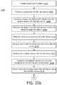
- a method of treating atrial fibrillation via irreversible electroporationmay include creating a transseptal opening into a left atrium, advancing a guidewire and a sheath into the left atrium through the transseptal opening, and advancing an ablation device into the left atrium over the guidewire.
- the ablation devicemay include a catheter shaft defining a longitudinal axis and a shaft lumen therethrough.
- a set of splinesmay be coupled to the catheter shaft. A distal portion of each spline of the set of splines may extend distally from a distal end of the catheter shaft.
- Each spline of the set of splinesmay include a set of electrodes formed on a surface of each spline of the set of splines.
- the set of splinesmay be configured for translation along the longitudinal axis to transition between a first configuration and a second configuration.
- the first configurationmay include the set of splines arranged substantially parallel to the longitudinal axis and the second configuration may include the set of splines arranged substantially perpendicular to the longitudinal axis.
- the methodmay further include the steps of transitioning the ablation device from the first configuration into the second configuration, recording first electrophysiology data of the left atrium, advancing the ablation device to toward a pulmonary vein of a set of pulmonary veins, delivering a pulse waveform to the pulmonary vein using the ablation device, recording second electrophysiology data of the left atrium after delivering the pulse waveform.
- the ablation devicemay be configured to generate a set of circumferential electric field lines generally parallel with a second longitudinal axis of a set of myocardial cells disposed circumferentially in an atrial wall when delivering the pulse waveform.
- a first access sitemay be created in a patient.
- the guidewiremay be advanced through the first access site and into a right atrium.
- the dilator and a sheathmay be advanced over the guidewire and into the right atrium.
- the dilatormay be advanced from the right atrium into the left atrium through an interatrial septum to create the transseptal opening.
- the transseptal openingmay be dilated using the dilator.
- the methodmay include creating a second access site in the patient for advancing a cardiac stimulator.
- the cardiac stimulatormay be advanced into a right ventricle.
- a pacing signal for cardiac stimulation of the heartmay be generated using the cardiac stimulator.
- the pacing signalmay be applied to the heart using the cardiac stimulator.
- the pulse waveformmay be generated in synchronization with the pacing signal.
- the first and second electrophysiology datamay include intracardiac ECG signal data of at least one pulmonary vein.
- the first and second electrophysiology datamay be recorded using the ablation device in the second configuration.
- a diagnostic cathetermay be advanced into the left atrium and may record the first and second electrophysiology data using the diagnostic catheter.
- the diagnostic cathetermay be advanced through a jugular vein.
- the ablation device disposed in the left atriummay transition from the first configuration into the second configuration without contacting an atrial wall and the pulmonary vein.
- the ablation devicemay be disposed in an endocardial space of the left atrium.
- the ablation devicemay be in contact with a pulmonary vein antrum.
- the set of splinesmay be in contact with the pulmonary vein ostium and form a “C” shape.
- a first set of electrodes of a first spline of the set of splinesmay be configured as an anode, and a second set of electrodes of a second spline of the set of splines may be configured as a cathode.
- the first splinemay be non-adjacent to the second spline.
- the first set of electrodesmay include one electrode and the second set of electrodes may include at least two electrodes.
- a radiopaque portion of the ablation devicemay be fluoroscopically imaged during one or more steps.
- the first access sitemay be a femoral vein.
- the interatrial septummay include a fossa ovalis.
- the pulse waveformmay be generated using a signal generator coupled to the ablation device.
- the set of splinesmay be transitioned from the second configuration after ablation of the pulmonary vein, and the ablation device may be advanced to another pulmonary vein of the set of pulmonary veins.
- the pulse waveformmay include a first level of a hierarchy of the pulse waveform including a first set of pulses, each pulse having a pulse time duration, a first time interval separating successive pulses.
- a second level of the hierarchy of the pulse waveformmay include a plurality of first sets of pulses as a second set of pulses, a second time interval separating successive first sets of pulses, the second time interval being at least three times the duration of the first time interval.
- a third level of the hierarchy of the pulse waveformmay include a plurality of second sets of pulses as a third set of pulses, a third time interval separating successive second sets of pulses, the third time interval being at least thirty times the duration of the second level time interval.
- the pulse waveformmay include a time offset with respect to the pacing signal.
- the ablation devicemay include a handle, the catheter shaft coupled to a proximal end of the handle.
- the methodmay include translating the set of splines along the first longitudinal axis to transition the set of splines between the first configuration and the second configuration using the handle.
- the handlemay be rotated to transition the ablation device between a lock configuration and an unlock configuration.
- the lock configurationmay fix a translational position of the set of splines relative to the catheter shaft and the unlock configuration may permit translation of the set of splines relative to the catheter shaft.
- a signal generatormay be electrically coupled to the proximal end of the handle.
- the signal generatormay be electrically coupled to the proximal end of the handle using an extension cable.
- the pulse waveformmay be between about 500 V and about 3,000 V.
- the set of splines in the second configurationmay be visually confirmed as not in contact with the pulmonary vein. An antral apposition of the set of splines in contact with the pulmonary vein may be visually confirmed.
- a first set of electrodes of a first spline of the set of splinesmay be configured as anodes.
- a second set of electrodes of a second spline of the set of splinesmay be configured as cathodes.
- the pulse waveformmay be delivered to the first set of electrodes and the second set of electrodes.
- an ablation device deployed in the second configurationmay appose tissue (e.g., an atrial surface) such that one or more electrodes formed on each surface of at least two splines may be suitably polarized to generate an electric field in atrial tissue.
- the electric fieldmay have a field direction that is generally aligned in a circumferential direction of the atrial tissue. This circumferential alignment of the electric field with tissue may enhance the safety, efficiency and effectiveness of irreversible electroporation to tissue and yield more effective ablative lesions with a reduction in total energy delivered.
- FIG. 1is a block diagram of an electroporation system, according to embodiments.
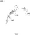
- FIG. 2is a perspective view of an ablation catheter, according to embodiments.
- FIG. 3is a perspective view of an ablation catheter, according to other embodiments.
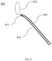
- FIG. 4is a perspective view of an ablation catheter, according to other embodiments.
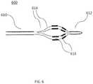
- FIG. 5is a detailed perspective view of a distal portion of an ablation catheter, according to other embodiments.
- FIG. 6is a side view of an ablation catheter, according to other embodiments.
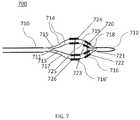
- FIG. 7is a side view of an ablation catheter, according to other embodiments.
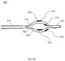
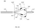
- FIGS. 8A-8Bare views of an ablation catheter, according to other embodiments.
- FIG. 8Ais a side view and
- FIG. 8Bis a front cross-sectional view.
- FIGS. 9A-9Eare each side views of an ablation catheter, according to other embodiments.
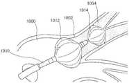
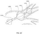
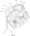
- FIG. 10is a perspective view of a balloon ablation catheter disposed in a left atrial chamber of a heart, according to other embodiments.
- FIG. 11is a cross-sectional view of a balloon ablation catheter disposed in a left atrial chamber of a heart, according to other embodiments.
- FIGS. 12A-12Bare schematic views of a return electrode of an ablation system, according to embodiments.
- FIG. 12Aillustrates an unenergized electrode and
- FIG. 12Billustrates an energized electrode.
- FIG. 13illustrates a method for tissue ablation, according to embodiments.
- FIG. 14illustrates a method for tissue ablation, according to other embodiments.
- FIG. 15is an illustration of the ablation catheter depicted in FIG. 2 disposed in a left atrial chamber of a heart.
- FIG. 16is an illustration of the ablation catheter depicted in FIG. 3 disposed in a left atrial chamber of a heart.
- FIG. 17is an illustration of two of the ablation catheters depicted in FIG. 4 disposed in a left atrial chamber of a heart.
- FIG. 18is an illustration of the ablation catheter depicted in FIG. 5 disposed in a left atrial chamber of a heart.
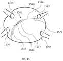
- FIGS. 19A-19Bare illustrative views of a set of electrodes disposed in a pulmonary vein ostium, according to other embodiments.
- FIG. 19Ais a schematic perspective view and
- FIG. 19Bis a cross-sectional view.
- FIGS. 20A-20Bare illustrative views of an electric field generated by electrodes disposed in a pulmonary vein ostium, according to other embodiments.
- FIG. 20Ais a schematic perspective view and FIG. 20B is a cross-sectional view.
- FIG. 21is an example waveform showing a sequence of voltage pulses with a pulse width defined for each pulse, according to embodiments.
- FIG. 22schematically illustrates a hierarchy of pulses showing pulse widths, intervals between pulses, and groupings of pulses, according to embodiments.
- FIG. 23provides a schematic illustration of a nested hierarchy of monophasic pulses displaying different levels of nested hierarchy, according to embodiments.
- FIG. 24is a schematic illustration of a nested hierarchy of biphasic pulses displaying different levels of nested hierarchy, according to embodiments.
- FIG. 25illustrates schematically a time sequence of electrocardiograms and cardiac pacing signals together with atrial and ventricular refractory time periods and indicating a time window for irreversible electroporation ablation, according to embodiments.
- FIG. 26Ais a perspective view of an ablation catheter, according to other embodiments.
- FIG. 26Bis a side view of the ablation catheter depicted in FIG. 26A disposed in a left atrial chamber of a heart, adjacent to a pulmonary vein antrum.
- FIG. 26Cis a top view of a simulation of the ablation catheter depicted in FIG. 26B , illustrating selective electrode activation according to embodiments.
- FIG. 26Dis a simulated illustration of tissue ablation in a pulmonary vein antrum, according to embodiments.
- FIG. 26Eis another simulated illustration of tissue ablation in a pulmonary vein antrum, according to embodiments.
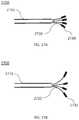
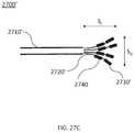
- FIGS. 27A-27Care each side views of an ablation catheter, according to other embodiments.
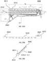
- FIG. 28Ais a side view of an ablation device, according to other embodiments.
- FIG. 28Bis a cross-sectional view of a spline of the ablation device of FIG. 28A , according to embodiments.
- FIG. 28Cis a detailed side view of a catheter of the ablation device of FIG. 28A in an expanded configuration, according to embodiments.
- FIG. 28Dis a front view of the catheter illustrated in FIG. 28C , according to embodiments.
- FIG. 28Eis a side view of the ablation device of FIG. 28A with the catheter of the ablation device being in the expanded configuration illustrated in FIG. 28C , according to other embodiments.
- FIG. 29Ais an image of a side view of a catheter of an ablation device, according to other embodiments.
- FIG. 29Bis an image of a perspective view of the catheter of FIG. 29A , according to other embodiments.
- FIG. 30Ais a cross-sectional side view of a handle of an ablation device, according to embodiments.
- FIG. 30Bis a cut-away side view of a translation member of the ablation device of FIG. 30A , according to embodiments.
- FIG. 30Cis a cut-away perspective view of a translation member of FIG. 30B , according to other embodiments.
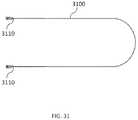
- FIG. 31is a side view of an extension cable useable with the ablation device of FIG. 28A , according to embodiments.
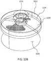
- FIGS. 32A-32Bare perspective views of an ablation device in a pulmonary vein ostium, according to embodiments.
- FIGS. 32C-32Dillustrate simulations of current density of an ablation device in the region of a pulmonary vein antrum, according to embodiments.
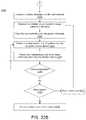
- FIGS. 33A-33Billustrate a method for tissue ablation, according to other embodiments.
- An irreversible electroporation systemas described herein may include a signal generator and a processor configured to apply one or more voltage pulse waveforms to a selected set of electrodes of an ablation device to deliver energy to a region of interest (e.g., ablation energy for a set of tissue in a pulmonary vein ostium or antrum).
- a region of intereste.g., ablation energy for a set of tissue in a pulmonary vein ostium or antrum.
- the pulse waveforms disclosed hereinmay aid in therapeutic treatment of a variety of cardiac arrhythmias (e.g., atrial fibrillation).
- one or more electrodes of the ablation devicemay have an insulated electrical lead configured for sustaining a voltage potential of at least about 700 V without dielectric breakdown of its corresponding insulation.
- the electrodesmay be independently addressable such that each electrode may be controlled (e.g., deliver energy) independently of any other electrode of the device. In this manner, the electrodes may deliver different energy waveforms with different timing synergistically for electroporation of tissue.
- electroporationrefers to the application of an electric field to a cell membrane to change the permeability of the cell membrane to the extracellular environment.
- reversible electroporationrefers to the application of an electric field to a cell membrane to temporarily change the permeability of the cell membrane to the extracellular environment.
- a cell undergoing reversible electroporationcan observe the temporary and/or intermittent formation of one or more pores in its cell membrane that close up upon removal of the electric field.
- irreversible electroporationrefers to the application of an electric field to a cell membrane to permanently change the permeability of the cell membrane to the extracellular environment.
- a cell undergoing irreversible electroporationcan observe the formation of one or more pores in its cell membrane that persist upon removal of the electric field.
- Pulse waveforms for electroporation energy delivery as disclosed hereinmay enhance the safety, efficiency and effectiveness of energy delivery to tissue by reducing the electric field threshold associated with irreversible electroporation, thus yielding more effective ablative lesions with a reduction in total energy delivered.
- the voltage pulse waveforms disclosed hereinmay be hierarchical and have a nested structure.
- the pulse waveformmay include hierarchical groupings of pulses having associated timescales.
- the methods, systems, and devices disclosed hereinmay comprise one or more of the methods, systems, and devices described in International Application Serial No. PCT/US2016/057664, filed on Oct. 19, 2016, and titled “SYSTEMS, APPARATUSES AND METHODS FOR DELIVERY OF ABLATIVE ENERGY TO TISSUE,” the contents of which are hereby incorporated by reference in its entirety.
- the systemsmay further include a cardiac stimulator used to synchronize the generation of the pulse waveform to a paced heartbeat.
- the cardiac stimulatormay electrically pace the heart with a cardiac stimulator and ensure pacing capture to establish periodicity and predictability of the cardiac cycle.
- a time window within a refractory period of the periodic cardiac cyclemay be selected for voltage pulse waveform delivery.
- voltage pulse waveformsmay be delivered in the refractory period of the cardiac cycle so as to avoid disruption of the sinus rhythm of the heart.
- an ablation devicemay include one or more catheters, guidewires, balloons, and electrodes. The ablation device may transform into different configurations (e.g., compact and expanded) to position the device within an endocardial space.
- the systemmay optionally include one or more return electrodes.
- one or more cathetersmay be advanced in a minimally invasive fashion through vasculature to a target location.
- an ablation devicemay be advanced through vasculature over a guidewire and through a deflectable sheath.
- the sheathmay be configured for deflecting at least about 180 degrees and aid in guiding an ablation catheter through vasculature and one or more predetermined targets (e.g., pulmonary vein ostia).
- a dilatormay be advanced over a guidewire and configured for creating and dilating a transseptal opening during and/or prior to use.
- the electrodes through which the voltage pulse waveform is deliveredmay be disposed on an epicardial device or on an endocardial device.
- the methods described heremay include introducing a device into an endocardial space of the left atrium of the heart and disposing the device in contact with a pulmonary vein ostium.
- a pulse waveformmay be generated and delivered to one or more electrodes of the device to ablate tissue.
- the pulse waveformmay be generated in synchronization with a pacing signal of the heart to avoid disruption of the sinus rhythm of the heart.
- the electrodesmay be configured in anode-cathode subsets.
- the pulse waveformmay include hierarchical waveforms to aid in tissue ablation and reduce damage to healthy tissue.
- a system for ablating tissue described heremay include a signal generator and an ablation device having one or more electrodes for the selective and rapid application of DC voltage to drive electroporation.
- the systems and devicesmay be deployed epicardially and/or endocardially to treat atrial fibrillation. Voltages may be applied to a selected subset of the electrodes, with independent subset selections for anode and cathode electrode selections.
- a pacing signal for cardiac stimulationmay be generated and used to generate the pulse waveform by the signal generator in synchronization with the pacing signal.
- FIG. 1illustrates an ablation system ( 100 ) configured to deliver voltage pulse waveforms.
- the system ( 100 )may include an apparatus ( 120 ) including a signal generator ( 122 ), processor ( 124 ), memory ( 126 ), and cardiac stimulator ( 128 ).
- the apparatus ( 120 )may be coupled to an ablation device ( 110 ), and optionally to a pacing device ( 130 ) and/or an optional return electrode ( 140 ) (e.g., a return pad, illustrated here with dotted lines).
- the signal generator ( 122 )may be configured to generate pulse waveforms for irreversible electroporation of tissue, such as, for example, pulmonary vein ostia.
- the signal generator ( 122 )may be a voltage pulse waveform generator and deliver a pulse waveform to the ablation device ( 110 ).
- the return electrode ( 140 )may be coupled to a patient (e.g., disposed on a patient's back) to allow current to pass from the ablation device ( 110 ) through the patient and then to the return electrode ( 140 ) to provide a safe current return path from the patient (not shown).
- the processor ( 124 )may incorporate data received from memory ( 126 ), cardiac stimulator ( 128 ), and pacing device ( 130 ) to determine the parameters (e.g., amplitude, width, duty cycle, etc.) of the pulse waveform to be generated by the signal generator ( 122 ).
- the memory ( 126 )may further store instructions to cause the signal generator ( 122 ) to execute modules, processes and/or functions associated with the system ( 100 ), such as pulse waveform generation and/or cardiac pacing synchronization.
- the memory ( 126 )may be configured to store pulse waveform and/or heart pacing data for pulse waveform generation and/or cardiac pacing, respectively.
- the ablation device ( 110 )may include a catheter configured to receive and/or deliver the pulse waveforms described in more detail below.
- the ablation device ( 110 )may be introduced into an endocardial space of the left atrium and positioned to align one or more electrodes ( 112 ) to one or more pulmonary vein ostial or antral locations, and then deliver the pulse waveforms to ablate tissue.
- the ablation device ( 110 )may include one or more electrodes ( 112 ), which may, in some embodiments, be a set of independently addressable electrodes.
- Each electrodemay include an insulated electrical lead configured to sustain a voltage potential of at least about 700 V without dielectric breakdown of its corresponding insulation.
- the insulation on each of the electrical leadsmay sustain an electrical potential difference of between about 200 V to about 1,500 V across its thickness without dielectric breakdown.
- the electrodes ( 112 )may be grouped into one or more anode-cathode subsets such as, for example, a subset including one anode and one cathode, a subset including two anodes and two cathodes, a subset including two anodes and one cathode, a subset including one anode and two cathodes, a subset including three anodes and one cathode, a subset including three anodes and two cathodes, and/or the like.
- the pacing device ( 130 )may be suitably coupled to the patient (not shown) and configured to receive a heart pacing signal generated by the cardiac stimulator ( 128 ) of the apparatus ( 120 ) for cardiac stimulation.
- An indication of the pacing signalmay be transmitted by the cardiac stimulator ( 128 ) to the signal generator ( 122 ).
- an indication of a voltage pulse waveformmay be selected, computed, and/or otherwise identified by the processor ( 124 ) and generated by the signal generator ( 122 ).
- the signal generator ( 122 )is configured to generate the pulse waveform in synchronization with the indication of the pacing signal (e.g., within a common refractory window).
- the common refractory windowmay start substantially immediately following a ventricular pacing signal (or after a very small delay) and last for a duration of approximately 250 ms or less thereafter. In such embodiments, an entire pulse waveform may be delivered within this duration.
- a diagnostic devicee.g., mapping catheter
- electrophysiology datae.g., ECG signals
- a heart chambere.g., left atrium, left ventricle
- Electrophysiology datamay be recorded and used to generate an anatomical map that may be used to compare electrophysiology data recorded before and after energy delivery to determine the effectiveness of tissue ablation.
- the processor ( 124 )may be any suitable processing device configured to run and/or execute a set of instructions or code.
- the processormay be, for example, a general purpose processor, a Field Programmable Gate Array (FPGA), an Application Specific Integrated Circuit (ASIC), a Digital Signal Processor (DSP), and/or the like.
- the processormay be configured to run and/or execute application processes and/or other modules, processes and/or functions associated with the system and/or a network associated therewith (not shown).
- MOSFETmetal-oxide semiconductor field-effect transistor
- CMOScomplementary metal-oxide semiconductor
- ECLemitter-coupled logic
- polymer technologiese.g., silicon-conjugated polymer and metal-conjugated polymer-metal structures
- mixed analog and digitaland/or the like.
- the memory ( 126 )may include a database (not shown) and may be, for example, a random access memory (RAM), a memory buffer, a hard drive, an erasable programmable read-only memory (EPROM), an electrically erasable read-only memory (EEPROM), a read-only memory (ROM), Flash memory, etc.
- the memory ( 126 )may store instructions to cause the processor ( 124 ) to execute modules, processes and/or functions associated with the system ( 100 ), such as pulse waveform generation and/or cardiac pacing.
- the system ( 100 )may be in communication with other devices (not shown) via, for example, one or more networks, each of which may be any type of network.
- a wireless networkmay refer to any type of digital network that is not connected by cables of any kind.
- a wireless networkmay connect to a wireline network in order to interface with the Internet, other carrier voice and data networks, business networks, and personal networks.
- a wireline networkis typically carried over copper twisted pair, coaxial cable or fiber optic cables.
- wireline networksincluding, wide area networks (WAN), metropolitan area networks (MAN), local area networks (LAN), campus area networks (CAN), global area networks (GAN), like the Internet, and virtual private networks (VPN).
- WANwide area networks
- MANmetropolitan area networks
- LANlocal area networks
- CANcampus area networks
- GANglobal area networks
- VPNvirtual private networks
- networkrefers to any combination of combined wireless, wireline, public and private data networks that are typically interconnected through the Internet, to provide a unified networking and information access solution.
- FIG. 2is a perspective view of an ablation device ( 200 ) (e.g., structurally and/or functionally similar to the ablation device ( 110 )) including a catheter ( 210 ) and a guidewire ( 220 ) slidable within a lumen of the catheter ( 210 ).
- the guidewire ( 220 )may include a nonlinear distal portion ( 222 ) and the catheter ( 210 ) may be configured to be disposed over the guidewire ( 220 ) during use.
- the distal portion ( 222 ) of the guidewire ( 220 )may be shaped to aid placement of the catheter ( 210 ) in a lumen of the patient.
- a shape of the distal portion ( 222 ) of the guidewire ( 220 )may be configured for placement in a pulmonary vein ostium and/or the vicinity thereof, as described in more detail with respect to FIG. 15 .
- the distal portion ( 222 ) of the guidewire ( 220 )may include and/or be formed in an atraumatic shape that reduces trauma to tissue (e.g., prevents and/or reduces the possibility of tissue puncture).
- the distal portion ( 222 ) of the guidewire ( 220 )may include a nonlinear shape such as a circle, loop (as illustrated in FIG. 2 ), ellipsoid, or any other geometric shape.
- the guidewire ( 220 )may be configured to be resilient such that the guidewire having a nonlinear shape may conform to a lumen of the catheter ( 210 ) when disposed in the catheter ( 210 ), and re-form/otherwise regain the nonlinear shape when advanced out of the catheter ( 210 ).
- the catheter ( 210 )may similarly be configured to be resilient, such as for aiding advancement of the catheter ( 210 ) through a sheath (not shown).
- the shaped distal portion ( 222 ) of the guidewire ( 220 )may be angled relative to the other portions of the guidewire ( 220 ) and catheter ( 210 ).
- the catheter ( 210 ) and guidewire ( 220 )may be sized for advancement into an endocardial space (e.g., left atrium).
- a diameter of the shaped distal portion ( 222 ) of the guidewire ( 220 )may be about the same as a diameter of a lumen in which the catheter ( 230 ) is to be disposed.
- the catheter ( 210 )may be slidably advanced over the guidewire ( 220 ) so as to be disposed over the guidewire ( 220 ) during use.
- the distal portion ( 222 ) of the guidewire ( 220 ) disposed in a lumen (e.g., near a pulmonary vein ostium)may serve as a backstop to advancement of a distal portion of the catheter ( 210 ).
- the distal portion of the catheter ( 210 )may include a set of electrodes ( 212 ) (e.g., structurally and/or functionally similar to the electrode(s) ( 112 )) configured to contact an inner radial surface of a lumen (e.g., pulmonary vein ostium).
- the electrodes ( 212 )may include an approximately circular arrangement of electrodes configured to contact a pulmonary vein ostium. As shown in FIG. 2 , one or more electrodes ( 212 ) may include a series of metallic bands or rings disposed along a catheter shaft and be electrically connected together.
- the ablation device ( 200 )may comprise a single electrode having a plurality of bands, one or more electrodes each having its own band, and combinations thereof.
- the electrodes ( 212 )may be shaped to conform to the shape of the distal portion ( 222 ) of the guidewire ( 220 ).
- the catheter shaftmay include flexible portions between the electrodes to enhance flexibility. In other embodiments, one or more electrodes ( 212 ) may include a helical winding to enhance flexibility.
- Each of the electrodes of the ablation devices discussed hereinmay be connected to an insulated electrical lead (not shown) leading to a handle (not shown) coupled to a proximal portion of the catheter.
- the insulation on each of the electrical leadsmay sustain an electrical potential difference of at least 700V across its thickness without dielectric breakdown. In other embodiments, the insulation on each of the electrical leads may sustain an electrical potential difference of between about 200 V to about 2,000 V across its thickness without dielectric breakdown, including all values and sub-ranges in between. This allows the electrodes to effectively deliver electrical energy and to ablate tissue through irreversible electroporation.
- the electrodesmay, for example, receive pulse waveforms generated by a signal generator ( 122 ) as discussed above with respect to FIG. 1 .
- a guidewire ( 220 )may be separate from the ablation device ( 200 ) (e.g., the ablation device ( 200 ) includes the catheter ( 210 ) but not the guidewire ( 220 ).
- a guidewire ( 220 )may be advanced by itself into an endocardial space, and thereafter the catheter ( 210 ) may be advanced into the endocardial space over the guidewire ( 220 ).
- FIG. 3is a perspective view of another embodiment of an ablation device ( 300 ) (e.g., structurally and/or functionally similar to the ablation device ( 110 )) including a catheter ( 310 ) having a set of electrodes ( 314 ) provided along a distal portion ( 312 ) of the catheter ( 310 ).
- the distal portion ( 312 ) of the catheter ( 310 )may be nonlinear and form an approximately circle shape.
- a set of electrodes ( 314 )may be disposed along a nonlinear distal portion ( 312 ) of the catheter ( 310 ) may form a generally circular arrangement of electrodes ( 314 ).
- the electrodes ( 314 )may be disposed at a pulmonary vein ostium in order to deliver a pulse waveform to ablate tissue, as described in more detail with respect to FIG. 16 .
- the shaped distal portion ( 312 ) of the catheter ( 310 )may be angled relative to the other portions of the catheter ( 310 ).
- the distal portion ( 312 ) of the catheter ( 310 )may be generally perpendicular to an adjacent portion of the catheter ( 310 ).
- a handlemay be coupled to a proximal portion of the catheter ( 310 ) and may include a bending mechanism (e.g., one or more pull wires (not shown)) configured to modify the shape of the distal portion ( 312 ) of the catheter ( 310 ).
- a bending mechanisme.g., one or more pull wires (not shown)
- operation of a pull wire of the handlemay increase or decrease a circumference of the circular shape of the distal portion ( 312 ) of the catheter ( 310 ).
- the diameter of the distal portion ( 312 ) of the catheter ( 310 )may be modified to allow the electrodes ( 314 ) to be disposed near and/or in contact with a pulmonary vein ostium (e.g., in contact with an inner radial surface of the pulmonary vein).
- the electrodes ( 314 )may include a series of metallic bands or rings and be independently addressable.
- the pulse waveformmay be applied between the electrodes ( 314 ) configured in anode and cathode sets. For example, adjacent or approximately diametrically opposed electrode pairs may be activated together as an anode-cathode set. It should be appreciated that any of the pulse waveforms disclosed herein may be progressively or sequentially applied over a sequence of anode-cathode electrodes.
- FIG. 4is a perspective view of yet another embodiment of an ablation device ( 400 ) (e.g., structurally and/or functionally similar to the ablation device ( 110 )) including a catheter ( 410 ) and a guidewire ( 420 ) having a shaped, nonlinear distal portion ( 422 ).
- the guidewire ( 420 )may be slidable within a lumen of the catheter ( 410 ).
- the guidewire ( 420 )may be advanced through the lumen of the catheter ( 410 ) and a distal portion ( 422 ) of the guidewire ( 420 ) may be approximately circular shaped.
- the shape and/or diameter of the distal portion ( 422 ) of the guidewire ( 420 )may be modified using a bending mechanism as described above with respect to FIG. 3 .
- the catheter ( 410 )may be flexible so as to be deflectable.
- the catheter ( 410 ) and/or guidewire ( 420 )may be configured to be resilient such that they conform to a lumen in which they are disposed and assume a secondary shape when advanced out of the lumen.
- the distal portion ( 422 ) of the guidewire ( 420 )may be positioned at a target tissue site, such as, a pulmonary vein ostium.
- a distal end ( 412 ) of the catheter ( 410 )may be sealed off except where the guidewire ( 420 ) extends from such that the catheter ( 410 ) may electrically insulate the portion of the guidewire ( 420 ) within the lumen of the catheter ( 410 ).
- the distal end ( 412 ) of the catheter ( 410 )may include a seal having an opening that permits passage of the guidewire ( 420 ) upon application of force to form a compression hold (that may be fluid-tight) between the seal and the guidewire ( 420 ).
- the exposed distal portion ( 422 ) of the guidewire ( 420 )may be coupled to an electrode and configured to receive a pulse waveform from a signal generator and deliver the pulse waveform to tissue during use.
- a proximal end of the guidewire ( 420 )may be coupled to a suitable lead and connected to the signal generator ( 122 ) of FIG. 1 .
- the distal portion ( 422 ) of the guidewire ( 420 )may be sized such that it may be positioned at a pulmonary vein ostium in some cases, or in other cases at a pulmonary vein antrum.
- a diameter of the shaped distal portion ( 422 ) of the guidewire ( 420 )may be about the same as a diameter of a pulmonary vein ostium.
- the shaped distal portion ( 422 ) of the guidewire ( 420 )may be angled relative to the other portions of the guidewire ( 420 ) and catheter ( 410 ).
- the guidewire ( 420 )may include stainless steel, nitinol, platinum, or other suitable, biocompatible materials.
- the distal portion ( 422 ) of the guidewire ( 420 )may include a platinum coil physically and electrically attached to the guidewire ( 420 ).
- the platinum coilmay be an electrode configured for delivery of a voltage pulse waveform. Platinum is radiopaque and its use may increase flexibility to aid advancement and positioning of the ablation device ( 400 ) within an endocardial space.
- FIG. 5is a detailed perspective view of a flower-shaped distal portion of an ablation device ( 500 ) (e.g., structurally and/or functionally similar to the ablation device ( 110 )) including a set of electrodes ( 520 , 522 , 524 , 526 ) each extending from a pair of insulated lead segments ( 510 , 512 , 514 , 516 ). Each pair of adjacent insulated lead segments coupled to an uninsulated electrode (e.g., lead segments ( 510 , 512 ) and electrode ( 526 )) form a loop ( FIG. 5 illustrates a set of four loops).
- an ablation device500
- FIG. 5illustrates a set of four loops.
- the set of loops at the distal portion of the ablation device ( 500 )may be configured for delivering a pulse waveform to tissue.
- the ablation device ( 500 )may include a set of insulated lead segments ( 510 , 512 , 514 , 516 ) that branch out at a distal end of the device ( 500 ) to connect to respective exposed electrodes ( 520 , 522 , 524 , 526 ), as shown in FIG. 5 .
- the electrodes ( 520 , 522 , 524 , 526 )may include an exposed portion of an electrical conductor.
- one or more of the electrodes ( 520 , 522 , 524 , 526 )may include a platinum coil.
- the one or more segments ( 510 , 512 , 514 , 516 )may be coupled to a bending mechanism (e.g., strut, pull wire, etc.) controlled from a handle (not shown) to control a size and/or shape of the distal portion of the device ( 500 ).
- a bending mechanisme.g., strut, pull wire, etc.
- the electrodes ( 520 , 522 , 524 , 526 )may be flexible and form a compact first configuration for advancement into an endocardial space, such as adjacent to a pulmonary vein ostium. Once disposed at a desired location, the electrodes ( 520 , 522 , 524 , 526 ) may be transformed to an expanded second configuration when advanced out of a lumen, such as a sheath, to form a flower-shaped distal portion, as shown in FIG. 5 .
- the insulated lead segments ( 510 , 512 , 514 , 516 ) and electrodes ( 520 , 522 , 524 , 526 )may be biased to expand outward (e.g., spring open) into the second configuration when advanced out of a lumen (e.g., sheath) carrying the device ( 500 ).
- the electrodes ( 520 , 522 , 524 , 526 )may be independently addressable and each have an insulated electrical lead configured to sustain a voltage potential of at least about 700 V without dielectric breakdown of its corresponding insulation.
- the insulation on each of the electrical leadsmay sustain an electrical potential difference of between about 200 V to about 2,000 V across its thickness without dielectric breakdown.
- the ablation device ( 5000may be configured for delivering the pulse waveform to tissue during use via the set of electrodes ( 520 , 522 , 524 , 526 ).
- the pulse waveformmay be applied between the electrodes ( 520 , 522 , 524 , 526 ) configured in anode and cathode sets.
- approximately diametrically opposite electrode pairse.g., electrodes ( 520 , 524 ) and ( 522 , 526 )
- adjacent electrodesmay be configured as an anode-cathode pair.
- a first electrode ( 520 ) of the set of electrodesmay be configured as an anode and a second electrode ( 522 ) may be configured as a cathode.
- FIGS. 6-9E and 26A-27Cillustrate additional embodiments of an ablation device (e.g., structurally and/or functionally similar to the ablation device ( 110 )) that may be configured to deliver voltage pulse waveforms using a set of electrodes to ablate tissue and electrically isolate a pulmonary vein.
- the ablation devicemay be transformed from a first configuration to a second configuration such that the electrodes of the ablation device expand outward to contact a lumen of tissue (e.g., pulmonary vein antrum).
- FIG. 6is a side view of an embodiment of an ablation device ( 600 ) including a catheter shaft ( 610 ) at a proximal end of the device ( 600 ), a distal cap ( 612 ) of the device ( 600 ), and a set of splines ( 614 ) coupled thereto.
- the distal cap ( 612 )may include an atraumatic shape to reduce trauma to tissue.
- a proximal end of the set of splines ( 614 )may be coupled to a distal end of the catheter shaft ( 610 ), and a distal end of the set of splines ( 614 ) may be tethered to the distal cap ( 612 ) of the device ( 600 ).
- the ablation device ( 600 )may be configured for delivering a pulse waveform to tissue during use via one or more splines of the set of splines ( 614 ).
- Each spline ( 614 ) of the ablation device ( 600 )may include one or more jointly wired, or in some cases independently addressable electrodes ( 616 ) formed on a surface of the spline ( 614 ).
- Each electrode ( 616 )may include an insulated electrical lead configured to sustain a voltage potential of at least about 700 V without dielectric breakdown of its corresponding insulation. In other embodiments, the insulation on each of the electrical leads may sustain an electrical potential difference of between about 200 V to about 2,000 V across its thickness without dielectric breakdown.
- Each spline ( 614 )may include the insulated electrical leads of each electrode ( 616 ) formed in a body of the spline ( 614 ) (e.g., within a lumen of the spline ( 614 )).
- a single insulated leadmay carry strands connecting to different electrodes on the spline.
- FIG. 6illustrates a set of splines ( 614 ) where each spline ( 614 ) includes a pair of electrodes ( 616 ) having about the same size, shape, and spacing as the electrodes ( 616 ) of an adjacent spline ( 614 ). In other embodiments, the size, shape, and spacing of the electrodes ( 616 ) may differ.
- each spline of the set of splinesmay include a flexible curvature.
- the minimum radius of curvature of a splinecan be in the range of about 1 cm or larger.
- the set of splinesmay form a delivery assembly at a distal portion of the ablation device and be configured to transform between a first configuration where the set of splines bow radially outward from a longitudinal axis of the ablation device, and a second configuration where the set of splines are arranged generally parallel to the longitudinal axis of the ablation device. In this manner, the splines may more easily conform to the geometry of an endocardial space.
- the “basket” of splinescan have an asymmetric shape along the shaft length, so that one end (for example, the distal end) of the basket is more bulbous than the other end (for example, the proximal end) of the basket.
- the delivery assemblymay be disposed in the first configuration in contact with a pulmonary vein antrum and transformed to the second configuration prior to delivering a pulse waveform.
- a handlemay be coupled to the set of splines and the handle configured for affecting transformation of the set of splines between the first configuration and the second configuration.
- the electrical leads of at least two electrodes of the set of electrodesmay be electrically coupled at or near a proximal portion of the ablation device, such as, for example, within the handle.
- each of the electrodes ( 616 ) on a spline ( 614 )may be configured as an anode while each of the electrodes ( 616 ) on an adjacent spline ( 614 ) may be configured as a cathode.
- the electrodes ( 616 ) on one splinemay alternate between an anode and cathode with the electrodes of an adjacent spline having a reverse configuration (e.g., cathode and anode).
- the ablation device ( 600 )may include any number of splines, for example, 3, 4, 5, 6, 7, 8, 9, 10, 12, 14, 16, 18, 20, or more splines, including all values and sub-ranges in between.
- the ablation device ( 600 )may include 3 to 20 splines.
- the ablation device ( 600 )may include 6 to 12 splines.
- FIG. 7is a side view of another embodiment of an ablation device ( 700 ) including a catheter shaft ( 710 ) at a proximal end of the device ( 700 ), a distal cap ( 712 ) of the device ( 700 ), and a set of splines ( 714 ) coupled thereto.
- the distal cap ( 712 )may include an atraumatic shape.
- a proximal end of the set of splines ( 714 )may be coupled to a distal end of the catheter shaft ( 710 ), and a distal end of the set of splines ( 714 ) may be tethered to the distal cap ( 712 ) of the device ( 700 ).
- Each spline ( 714 ) of the ablation device ( 700 )may include one or more independently addressable electrodes ( 716 ) formed on a surface of the spline ( 714 ).
- Each electrode ( 716 )may include an insulated electrical lead configured to sustain a voltage potential of at least about 700 V without dielectric breakdown of its corresponding insulation. In other embodiments, the insulation on each of the electrical leads may sustain an electrical potential difference of between about 200 V to about 1500 V across its thickness without dielectric breakdown.
- Each spline ( 714 )may include the insulated electrical leads of each electrode ( 716 ) formed in a body of the spline ( 714 ) (e.g., within a lumen of the spline ( 714 )).
- a set of spline wires ( 718 , 719 )may be electrically conductive and electrically couple adjacent electrodes ( 716 ) disposed on different splines ( 714 ) such as electrodes ( 716 ) between a pair of splines ( 718 , 719 ) of the set of splines.
- the spline wires ( 718 , 719 )may extend in a transverse direction relative to a longitudinal axis of the ablation device ( 700 ).
- FIG. 7illustrates a set of splines ( 714 ) where each spline ( 714 ) includes a pair of electrodes ( 716 ) having about the same size, shape, and spacing as the electrodes ( 716 ) of an adjacent spline ( 714 ).
- the size, shape, and spacing of the electrodes ( 716 )may differ.
- the electrodes ( 716 ) electrically coupled to a first spline wire ( 718 )may differ in size and/or shape from electrodes ( 716 ′) electrically coupled to a second spline wire ( 719 ).
- the first spline wire ( 718 )may include a first set of spline wires ( 720 , 721 , 722 , 723 ), where each spline wire of the set of spline wires ( 720 , 721 , 722 , 723 ) may couple electrodes ( 716 ) between a different pair of splines of the set of splines ( 714 ).
- the set of spline wires ( 720 , 721 , 722 , 723 )may form a continuous loop between the electrodes ( 716 ) coupled thereto.
- the second spline wire ( 719 )may include a second set of spline wires ( 724 , 725 , 726 ), where each spline wire of the set of spline wires ( 724 , 725 , 726 ) may couple electrodes ( 716 ′) across the set of splines ( 714 ).
- the second set of spline wires ( 724 , 725 , 726 )may couple different electrodes ( 716 ′) across the set of splines ( 714 ) than the first set of spline wires ( 720 , 721 , 722 , 723 ).
- the first set of spline wires ( 720 , 721 , 722 , 723 )may form a first continuous loop between the electrodes ( 716 ) coupled thereto and the second set of spline wires ( 724 , 725 , 726 ) may form a second continuous loop between the electrodes ( 716 ′) coupled thereto.
- the first continuous loopmay be electrically isolated from the second continuous loop.
- the electrodes ( 716 ) coupled to the first continuous loopmay be configured as anodes and the electrodes ( 716 ) coupled to the second continuous loop may be configured as cathodes.
- a pulse waveformmay be delivered to the electrodes ( 716 ) of the first and second continuous loop.
- the spline wiressuch as 721 , 722 , 723 etc. can be replaced by similar electrical connections in the proximal part of the device (for example, in the device handle).
- the electrodes 716can all be electrically wired together in the handle of the device.
- the first spline wire ( 721 ) of the set of spline wires ( 720 , 721 , 722 , 723 )may couple electrodes ( 716 ) between a first spline ( 711 ) and a second spline ( 713 ) of the set of splines ( 714 ), and a second spline wire ( 720 ) of the set of spline wires ( 720 , 721 , 722 , 723 ) may couple electrodes ( 716 ) between the first spline ( 711 ) and a third spline ( 715 ) of the set of splines ( 714 ).
- the electrodes ( 716 ) coupled by the first spline wire ( 721 ) and the second spline wire ( 720 )may be configured as an anode and cathode (or vice-versa).
- the first spline wire ( 721 ) of the set of spline wires ( 720 , 721 , 722 , 723 )may couple the electrodes ( 716 ) between a first spline ( 711 ) and a second spline ( 713 ) of the set of splines ( 714 ), and a second spline wire ( 723 ) of the set of spline wires ( 720 , 721 , 722 , 723 ) may couple the electrodes ( 716 ) between a third spline ( 715 ) and a fourth spline ( 717 ) of the set of splines ( 714 ).
- a pulse waveformmay be delivered to the electrodes ( 716 ) coupled by the first spline wire ( 721 ) and the second spline wire ( 723 ).
- the electrical leads of at least two electrodes of the set of electrodesare electrically coupled at or near a proximal portion of the ablation device, such as, for example, within a handle.
- one or more of the spline wires ( 718 , 719 )may form a continuous loop between the electrically coupled electrodes ( 716 ).
- a first set of spline wires ( 718 )may form a first continuous loop between the electrodes ( 716 ) coupled thereto and a second set of spline wires ( 719 ) may form a second continuous loop between the electrodes ( 716 ) coupled thereto.
- the first continuous loopmay be electrically isolated from the second continuous loop.
- each of the electrodes ( 716 ) coupled to a first set of spline wires ( 718 )may be configured as an anode while each of the electrodes ( 716 ) coupled to a second set of spline wires ( 719 ) may be configured as a cathode.
- Each group of electrically coupled electrodes ( 716 )may be independently addressable.
- the electrical leads of at least two electrodes of the set of electrodesare electrically coupled at or near a proximal portion of the ablation device, such as, for example, within a handle.
- a spline wiremay electrically couple to a set of electrodes (e.g., 2, 3, 4, 5, etc.) without forming a continuous loop.
- a discontinuous loopmay be formed using two spline wires.
- the size, shape, and spacing of the electrodes ( 716 )may differ.
- the ablation device ( 700 )may include any number of splines, for example, 3, 4, 5, 6, 7, 8, 9, 10, 12, 14, 16, 18, 20, or more splines.
- the ablation device ( 700 )may include 3 to 20 splines.
- the ablation device ( 700 )may include 6 to 9 splines.
- FIGS. 8A-8Bare side and front cross-sectional views, respectively, of an ablation catheter ( 800 ).
- FIG. 8Ais a side view of an embodiment of an ablation device ( 800 ) including a catheter shaft ( 810 ) at a proximal end of the device ( 800 ), a distal cap ( 812 ) of the device ( 800 ), and a set of splines ( 814 ) coupled thereto.
- the distal cap ( 812 )may include an atraumatic shape.
- a proximal end of the set of splines ( 814 )may be coupled to a distal end of the catheter shaft ( 810 ), and a distal end of the set of splines ( 14 ) may be tethered to the distal cap ( 812 ) of the device ( 800 ).
- Each spline ( 814 ) of the ablation device ( 800 )may include one or more independently addressable electrodes ( 816 , 818 ) formed on a surface of the spline ( 814 ).
- Each electrode ( 816 , 818 )may include an insulated electrical lead configured to sustain a voltage potential of at least about 700 V without dielectric breakdown of its corresponding insulation.
- each spline ( 814 )may include the insulated electrical leads of each electrode ( 816 , 818 ) formed in a body of the spline ( 814 ) (e.g., within a lumen of the spline ( 814 )).
- One or more spline wires ( 817 , 819 )may be electrically conductive and electrically couple adjacent electrodes ( 816 , 818 ) disposed on different splines ( 814 ).
- the spline wires ( 817 , 819 )may extend in a transverse direction relative to a longitudinal axis of the ablation device ( 800 ).
- FIG. 8Bis a front cross-sectional view of FIG. 8A taken along the 8 B- 8 B line.
- Each spline wire( 817 , 819 , 821 , 823 ) electrically couples a pair of adjacent electrodes ( 816 , 818 , 820 , 822 ) on different splines.
- each coupled electrode pairmay be electrically isolated from each other.
- the coupled electrode pairmay be configured with a common polarity. Adjacent pairs of electrodes may be configured with opposite polarities (e.g., a first electrode pair configured as an anode and an adjacent second electrode pair configured as a cathode).
- the electrodes ( 816 ) coupled to a first set of spline wires ( 817 )may be configured as an anode while each of the electrodes ( 818 ) coupled to a second set of spline wires ( 819 ) may be configured as a cathode.
- each electrode formed on a spline ( 814 )may share a common polarity (e.g., configured as an anode or cathode).
- Each coupled electrode pairmay be independently addressable.
- the ablation device ( 800 )may include an even number of splines.
- the ablation device ( 800 )may include any number of splines, for example, 4, 6, 8, 10, or more splines.
- the ablation devicemay include 4 to 10 splines.
- the ablation devicemay include 6 to 8 splines.
- the spline wiressuch as 817 , 819 , etc. can be replaced by similar electrical connections in the proximal part of the device (for example, in the device handle).
- the electrodes ( 816 )can be electrically wired together in the handle of the device, so that these electrodes are at the same electric potential during ablation.
- FIG. 9Ais a side view of yet another embodiment of an ablation device ( 900 ) including a catheter shaft ( 910 ) at a proximal end of the device ( 900 ), a distal cap ( 912 ) of the device ( 900 ), and a set of splines ( 914 ) coupled thereto.
- the distal cap ( 912 )may include an atraumatic shape.
- a proximal end of the set of splines ( 914 )may be coupled to a distal end of the catheter shaft ( 910 ), and a distal end of the set of splines ( 914 ) may be tethered to the distal cap ( 912 ) of the device ( 900 ).
- Each spline ( 914 ) of the ablation device ( 900 )may include one or more independently addressable electrodes ( 916 , 918 ) formed on a surface of the spline ( 914 ).
- Each electrode ( 916 , 918 )may include an insulated electrical lead configured to sustain a voltage potential of at least about 700 V without dielectric breakdown of its corresponding insulation. In other embodiments, the insulation on each of the electrical leads may sustain an electrical potential difference of between about 200 V to about 2,000 V across its thickness without dielectric breakdown.
- Each spline ( 914 )may include the insulated electrical leads of each electrode ( 916 , 918 ) formed in a body of the spline ( 914 ) (e.g., within a lumen of the spline ( 914 )).
- FIG. 9Aillustrates a set of splines ( 914 ) where each spline ( 914 ) includes an electrode spaced apart or offset from an electrode of an adjacent spline ( 914 ).
- the set of splines ( 914 )including a first spline ( 920 ) and a second spline ( 922 ) adjacent to the first spline ( 920 ), wherein an electrode ( 916 ) of the first spline ( 920 ) is disposed closer to a distal end ( 912 ) of the ablation device ( 900 ) relative to an electrode ( 918 ) of the second spline ( 922 ).
- the size and shape of the electrodes ( 916 , 918 )may differ as well.
- adjacent distal electrodes ( 916 ) and proximal electrodes ( 918 )may form an anode-cathode pair.
- the distal electrodes ( 916 )may be configured as an anode and the proximal electrodes ( 918 ) may be configured as a cathode.
- the ablation device ( 900 )may include 3 to 12 splines.
- one electrode ( 916 , 918 )is formed on a surface of each spline ( 914 ) such that each spline ( 914 ) includes one insulated electrical lead.
- a lumen of the spline ( 914 )may therefore be reduced in diameter and allow the spline ( 914 ) to be thicker and more mechanically robust. Thus, dielectric breakdown of the insulation may be further reduced, thereby improving reliability and longevity of each spline ( 914 ) and the ablation device ( 900 ).
- the ablation device ( 900 )may include any number of splines, for example, 3, 4, 5, 6, 7, 8, 9, 10, 12, 14, 16, 18, 20, or more splines. In some embodiments, the ablation device ( 900 ) may include 3 to 20 splines. For example, in one embodiment, the ablation device ( 900 ) may include 6 to 10 splines.
- the shape of a bulb-like expanded structure ( 930 ) of the expanded set of splines ( 914 )may be asymmetric, for example with its distal portion being more bulbous or rounded than its proximal portion (e.g., see FIGS. 9B-9E ). Such a bulbous distal portion can aid in positioning the device at the ostium of a pulmonary vein.
- FIGS. 9B-9Eit is understood that unless indicated otherwise, components with similar references numbers to those in FIG. 9A (e.g., the electrode ( 916 ) in FIG. 9A and the electrode ( 916 ′) in FIG. 9B ) may be structurally and/or functionally similar.
- FIG. 9Billustrates the spline wires ( 914 ′, 920 ′, 922 ′) forming an expanded structure ( 930 ′) during use such as when deployed.
- a first plane ( 924 A′), also sometimes referred to as a proximal plane, of the expanded structure ( 930 ′)has a cross-sectional area that is different than a cross-sectional area at a second plane ( 924 B′) of the expanded structure ( 930 ′). As illustrated in FIG. 9B , in some embodiments, the cross-sectional area of the expanded structure ( 930 ′) at the second plane ( 924 B′) is greater than that at the first plane ( 924 A′).
- the electrode ( 916 ′) of the first spline ( 920 ′)is disposed closer to the distal cap ( 912 ′) of the ablation device ( 900 ′) relative to an electrode ( 918 ′) of the second spline ( 922 ′).
- FIG. 9Cillustrates the spline wires ( 914 ′′, 920 ′′, 922 ′′) forming an expanded structure ( 930 ′′) during use such as when deployed.
- a first plane ( 924 A′′), also sometimes referred to as a proximal plane, of the expanded structure ( 930 ′′)has a cross-sectional area that is different than a cross-sectional area at a second plane ( 924 B′′) of the expanded structure ( 930 ′′).
- the cross-sectional area of the expanded structure ( 930 ′′) at the second plane ( 924 B′′)is greater than that at the first plane ( 924 A′′).
- 9Cmay refer to planes orthogonal to the longitudinal axis of the catheter shaft ( 910 ′′) that are each formed up to about 1 cm, about 2 cm, and about 3 cm or more (including all values and sub-ranges in between) from the distal end of the catheter shaft ( 910 ′′) and the proximal end of the distal cap ( 912 ′′), respectively.
- multiple electrodesmay be present on each spline wire, and some electrodes may be equidistant from the distal cap ( 912 ′′).
- relatively distal electrodessuch as 932 ′′ and 934 ′′ may be apposed at or proximal/antral to a pulmonary vein ostium during use for ablation delivery to generate an ostial circumferential lesion around a pulmonary vein.
- FIG. 9Dillustrates the spline wires ( 914 ′′′, 920 ′′′, 922 ′′′) forming an expanded structure ( 930 ′′′) during use such as when deployed.
- the spline wires ( 914 ′′′, 920 ′′′, 922 ′′′)converge at their distal ends to a point ( 928 ′′′) that lies inside/within the expanded structure ( 930 ′′′). As illustrated in FIG.
- At least some electrodes ( 932 ′′′, 934 ′′′) on the spline wires ( 914 ′′′, 920 ′′′, 922 ′′′)may lie in a distal end plane ( 926 ′′′) of the expanded structure ( 930 ′′′).
- the term “distal end plane” as used with respect to FIG. 9Dmay refer to a plane orthogonal to the longitudinal axis of the catheter shaft ( 910 ′′′) that passes through a distal boundary of the expanded structure ( 930 ′′′).
- the expanded structure ( 930 ′′′)may be pressed against, for example, an endocardial surface such as the posterior wall of the left atrium in order to directly generate lesions thereupon by activation of appropriate electrodes in the distal end plane using any suitable combination of polarities.
- distal electrodes ( 932 ′′′, 934 ′′′)may be pressed against an endocardial surface.
- Distal electrodes ( 932 ′′′, 934 ′′′)may be configured with opposite polarities.
- adjacent electrodes on the same splinemay have the same polarity such that distal electrode ( 934 ′′′) may have the same polarity as proximal electrode ( 933 ) and likewise distal electrode ( 932 ′′′) may have the same polarity as proximal electrode ( 935 ). Electrodes ( 934 ′′′, 933 ) may have the opposite polarity as electrodes ( 932 ′′′, 935 ).
- adjacent distal electrodes ( 934 ′′′) and proximal electrodes ( 933 )may form an anode-cathode pair.
- the distal electrodes ( 934 ′′′)may be configured as an anode and the proximal electrodes ( 933 ) may be configured as a cathode.
- the electrodes ( 2630 ) on one splinemay alternate between an anode and cathode with the electrodes of an adjacent spline having a reverse configuration (e.g., cathode and anode).
- FIG. 9Eillustrates the spline wires ( 944 , 940 , 942 ) forming an expanded structure ( 950 ) during use such as when deployed.
- the spline wires ( 944 , 940 , 942 )converge at their distal ends at a proximal end of a distal cap ( 912 ′′′′) inside/within the expanded structure ( 950 ).
- at least some electrodes ( 952 , 954 ) on the spline wires ( 944 , 940 )may lie in a distal end plane ( 946 ) of the expanded structure ( 950 ).
- the expanded structure ( 950 )may be pressed against, for example, the posterior wall of the left atrium in order to directly generate lesions thereupon by activation of appropriate electrodes in the distal end plane ( 946 ) using any suitable combination of polarities.
- the electrodes 952 and 954may be configured with opposite polarities. Relative to the expanded structure ( 930 ′′′′) in FIG. 9D , the expanded structure ( 950 ) in FIG.
- the cross-sectional area of the expanded structure ( 930 ′′′′) at the distal end plane ( 926 ′′′′)is less than that the cross-sectional area of the expanded structure ( 950 ) at the distal end plane ( 946 ).
- each of the splinesmay include a polymer and define a lumen so as to form a hollow tube.
- the one or more electrodes of the ablation device described hereinmay include a diameter from about 0.2 mm to about 2.0 mm and a length from about 0.2 mm to about 5.0 mm.
- the electrodemay include a diameter of about 1 mm and a length of about 1 mm.
- the electrodesmay be independently addressable, the electrodes may be energized in any sequence using any pulse waveform sufficient to ablate tissue by irreversible electroporation. For example, different sets of electrodes may deliver different sets of pulses (e.g., hierarchical pulse waveforms), as discussed in further detail below.
- the size, shape, and spacing of the electrodes on and between the splinesmay be configured to deliver contiguous/transmural energy to electrically isolate one or more pulmonary veins.
- alternate electrodesfor example, all the distal electrodes
- ablationcan be delivered rapidly with all electrodes activated at the same time.
- a variety of such electrode pairing optionsexist and may be implemented based on the convenience thereof.
- FIG. 26Ais a perspective view of an embodiment of an ablation device ( 2600 ) having a flower-like shape and including a catheter shaft ( 2610 ) at a proximal end of the device ( 2600 ), a distal cap ( 2612 ) of the device ( 2600 ), and a set of splines ( 2620 ) coupled thereto.
- a spline shaft ( 2614 )may be coupled at a proximal end to the proximal end of the handle (not shown) and coupled at a distal end to the distal cap ( 2612 ).
- the distance between the distal cap 2612 and the catheter shaft 2610may be less than about 8 mm.
- the spline shaft ( 2614 ) and distal cap ( 2612 )may be translatable along a longitudinal axis ( 2616 ) of the ablation device ( 2600 ).
- the spline shaft ( 2614 ) and distal cap ( 2612 )may move together.
- the spline shaft ( 2614 )may be configured to slide within a lumen of the catheter shaft ( 2610 ).
- the distal cap ( 2612 )may include an atraumatic shape to reduce trauma to tissue.
- a proximal end of each spline of the set of splines ( 2620 )may pass through a distal end of the catheter shaft ( 2610 ) and be tethered to the catheter shaft within the catheter shaft lumen, and a distal end of each spline of the set of splines ( 2620 ) may be tethered to the distal cap ( 2612 ) of the device ( 2600 ).
- the ablation device ( 2600 )may be configured for delivering a pulse waveform, as disclosed for example in FIGS. 21-25 , to tissue during use via one or more splines of the set of splines ( 2620 ).
- Each spline ( 2620 ) of the ablation device ( 2600 )may include one or more jointly wired electrodes ( 2630 ) formed on a surface of the spline ( 2620 ), in some embodiments. In other embodiments, one or more of the electrodes ( 2630 ) on a given spline may be independently addressable electrodes ( 2630 ).
- Each electrode ( 2630 )may include an insulated electrical lead configured to sustain a voltage potential of at least about 700 V without dielectric breakdown of its corresponding insulation. In other embodiments, the insulation on each of the electrical leads may sustain an electrical potential difference of between about 200 V to about 2,000 V across its thickness without dielectric breakdown.
- Each spline ( 2620 )may include the insulated electrical leads of each electrode ( 2630 ) within a body of the spline ( 2620 ) (e.g., within a lumen of the spline ( 2620 )).
- FIG. 26Aillustrates a set of splines ( 2620 ) where each spline includes a set of electrodes ( 2632 or 2634 ) having about the same size, shape, and spacing as the electrodes ( 2634 or 2632 ) of an adjacent spline ( 2620 ). In other embodiments, the size, shape, and spacing of the electrodes ( 2632 , 2634 ) may differ.
- each spline ( 2620 )may vary based on the number of electrodes ( 2630 ) formed on each spline ( 2620 ) which may correspond to the number of insulated electrical leads in the spline ( 2620 ).
- the splines ( 2620 )may have the same or different materials, thickness, and/or length.
- Each spline of the set of splines ( 2620 )may include a flexible curvature so as to rotate, or twist and bend and form a petal-shaped curve such as shown in FIGS. 26A-26C .
- the minimum radius of curvature of a spline in the petal-shaped configurationmay be in the range of about 7 mm to about 25 mm.
- the set of splinesmay form a delivery assembly at a distal portion of the ablation device ( 2600 ) and be configured to transform between a first configuration where the set of splines are arranged generally parallel to the longitudinal axis of the ablation device ( 2600 ), and a second configuration where the set of splines rotate around, or twist and bend, and generally bias away from the longitudinal axis of the ablation device ( 2600 ).
- each spline of the set of splinesmay lie in one plane with the longitudinal axis of the ablation device.
- each spline of the set of splinesmay bias away from the longitudinal axis to form a petal-like curve arranged generally perpendicular to the longitudinal axis.
- the set of splines ( 2620 )twist and bend and bias away from the longitudinal axis of the ablation device ( 2600 ), thus allowing the splines ( 2620 ) to more easily conform to the geometry of an endocardial space, and particularly adjacent to the opening of a pulmonary ostium.
- the second configurationmay, for example, resemble the shape of a flower, when the ablation device is viewed from the front as best shown in FIG. 26C .
- the each spline in the set of splines in the second configurationmay twist and bend to form a petal-like curve that, when viewed from front, displays an angle between the proximal and distal ends of the curve of more than 180 degrees.
- the set of splinesmay further be configured to transform from a second configuration to a third configuration where the set of splines ( 2620 ) may be impressed (e.g., in contact with) against target tissue such as tissue surrounding a pulmonary vein ostium.
- the spline shaft ( 2614 ) coupled to the set of splines ( 2620 )may allow each spline of the set of splines ( 2620 ) to bend and twist relative to the catheter shaft ( 2610 ) as the spline shaft ( 2614 ) slides within a lumen of the catheter shaft ( 2610 ).
- the set of splines ( 2620 )may form a shape generally parallel to a longitudinal axis of the spline shaft ( 2614 ) when undeployed, be wound (e.g., helically, twisted) about an axis ( 2660 ) parallel to the longitudinal axis of the spline shaft ( 2620 ) when fully deployed, and form any intermediate shape (such as a cage or barrel) in-between as the spline shaft ( 2614 ) slides within a lumen of the catheter shaft ( 2610 ).
- any intermediate shapesuch as a cage or barrel
- the set of splines in the first configurationmay be wound about an axis ( 2660 ) parallel to the longitudinal axis of the catheter shaft ( 2610 ) in some portions along its length but elsewhere may otherwise be generally parallel to the longitudinal axis of the catheter shaft ( 2610 ).
- the spline shaft ( 2614 )may be retracted into the catheter shaft ( 2610 ) to transform the ablation device ( 2600 ) from the first configuration to the second configuration where the splines ( 2620 ) are generally angled or offset (e.g., perpendicular) with respect to the longitudinal axis of the catheter shaft ( 2610 ) and twisted. As shown in the front view of FIG.
- each spline ( 2620 )may form a twisting loop in this front view projection.
- each spline ( 2620 )has a set of electrodes ( 2630 ) having the same polarity.
- each spline of the set of splines ( 2620 )may form a twisted loop such that each spline overlaps one or more other splines.
- the number and spacing of the electrodes ( 2630 ), as well as the rotated twist of the spline ( 2620 ),may be configured by suitable placement of electrodes along each spline to prevent overlap of an electrode ( 2630 ) on one spline with an electrode of an adjacent, overlapping spline ( 2620 ).
- a spline having a set of anode electrodes ( 2632 )may be activated together to deliver pulse waveforms for irreversible electroporation. Electrodes on other splines may be activated together as cathode electrodes such as electrodes ( 2634 ) and ( 2635 ) on their respective splines so at to form an anode-cathode pairing for delivery of pulse waveforms for irreversible electroporation, as shown in FIG. 26C .
- the anode-cathode pairing and pulse waveform deliverycan be repeated sequentially over a set of such pairings.
- the splines ( 2620 )may be activated sequentially in a clockwise or counter-clockwise manner.
- the cathode splinesmay be activated sequentially along with respective sequential anode spline activation until ablation is completed.
- the order of activation within the electrode of each splinemay be varied as well.
- the electrodes in a splinemay be activated all at once or in a predetermined sequence.
- the delivery assemblymay be disposed in the first configuration prior to delivering a pulse waveform and transformed to the second configuration to make contact with the pulmonary vein ostium or antrum.
- a handlemay be coupled to the spline shaft ( 2614 ) and the handle configured for affecting transformation of the set of splines between the first configuration and the second configuration.
- the handlemay be configured to translate the spline shaft ( 2614 ) and distal cap ( 2612 ) relative to the catheter shaft ( 2610 ), thereby actuating the set of splines ( 2620 ) coupled to the distal cap and causing them to bend and twist.
- the proximal ends of the splines ( 2620 )may be fixed to the spline shaft ( 2614 ) thereby generating buckling of the splines ( 2620 ) resulting in a bending and twisting motion of the splines ( 2620 ), for example, as the distal cap ( 2612 ) and spline shaft ( 2614 ) are pulled back relative to the catheter shaft ( 2610 ) that may be held by a user.
- a distal end of the set of splines ( 2620 ) tethered to the distal cap ( 2612 )may be translated by up to about 60 mm along the longitudinal axis of the ablation device to actuate this change in configuration.
- translation of an actuating member of the handlemay bend and twist the set of splines ( 2620 ).
- actuation of a knob, wheel, or other rotational control mechanism in the device handlemay result in a translation of the actuating member or spline shaft and result in bending and twisting of the splines ( 2620 ).
- the electrical leads of at least two electrodes of the set of electrodes ( 2630 )may be electrically coupled at or near a proximal portion of the ablation device ( 2600 ), such as, for example, within the handle.
- each spline of the set of splines ( 2620 )may be biased laterally away from the longitudinal axis of the spline shaft ( 2614 ) by up to about 3 cm.
- the spline shaft ( 2614 )may comprise a hollow lumen.
- the cross section of a splinemay be asymmetric so as to have a larger bending stiffness in one bending plane of the spline orthogonal to the plane of the cross section than in a different bending plane.
- Such asymmetric cross sectionsmay be configured to present a relatively larger lateral stiffness and thereby may deploy with minimal overlap of the petal-shaped curves of each spline and its neighbors in the final or fully-deployed configuration.
- each of the electrodes ( 2632 ) on a spline ( 2620 )may be configured as an anode while each of the electrodes ( 2634 ) on a different spline may be configured as a cathode.
- the electrodes ( 2630 ) on one splinemay alternate between an anode and cathode with the electrodes of another spline having a reverse configuration (e.g., cathode and anode).
- the spline electrodesmay be electrically activated in sequential manner to deliver a pulse waveform with each anode-cathode pairing.
- the electrodesmay be electrically wired together within the spline, while in alternate embodiments they may be wired together in the handle of the device, so that these electrodes are at the same electric potential during ablation.
- the size, shape, and spacing of the electrodes ( 2630 )may differ as well.
- adjacent distal electrodes and proximal electrodesmay form an anode-cathode pair.
- the distal electrodesmay be configured as an anode and the proximal electrodes may be configured as a cathode.
- the ablation device ( 2600 )may include any number of splines, for example, 2, 3, 4, 5, 6, 7, 8, 9, 10, 12, 14, 16, 18, 20, or more splines, including all values and sub-ranges in between. In some embodiments, the ablation device ( 2600 ) may include 3 to 20 splines. For example, the ablation device ( 2600 ) may include from 4 to 12 splines.
- Each of the splines of the set of splines ( 2620 )may include respective electrodes ( 2630 ) having an atraumatic shape to reduce trauma to tissue.
- the electrodes ( 2630 )may have an atraumatic shape including a rounded, flat, curved, and/or blunted portion configured to contact endocardial tissue.
- the electrodes ( 2630 )may be located along any portion of the spline ( 2620 ) distal to the catheter shaft ( 2610 ).
- the electrodes ( 2630 )may have the same or different sizes, shapes, and/or location along respective splines.
- the electrodes in the second configurationmay be held close to or placed against a section of atrial wall of the left atrium in order to directly generate lesions thereupon by activation of appropriate electrodes using any suitable combination of polarities, as described herein.
- the set of splines ( 2620 )may be placed in contact against the atrial wall ( 2654 ) of atrium ( 2652 ) adjacent a pulmonary vein ( 2650 ) (e.g., ostium or antrum).
- FIG. 26Dis a schematic illustration of ablation ( 2664 ) generated by the ablation device ( 2600 ) having a set of eight splines on tissue, such as the tissue surrounding a pulmonary vein ostium.
- activation of one or more of the electrodes ( 2630 ) on one or more of the splines ( 2620 )may generate one or more corresponding ablation areas ( 2664 ) along a wall ( 2654 ) of a pulmonary vein antrum or ostium.
- an outline of the ablation areas ( 2664 ) in the pulmonary vein ostiummay have a diameter of between about 2 cm and about 6 cm, and may be about 3.5 cm. In this manner, a contiguous, transmural lesion may be generated, resulting in electrical isolation of the pulmonary vein, which is a desired therapeutic outcome.
- FIG. 26Eis another schematic illustration of ablation ( 2664 ) generated by the ablation device ( 2600 ) having a set of five splines on tissue, such as the tissue surrounding a pulmonary vein ostium.
- tissuesuch as the tissue surrounding a pulmonary vein ostium.
- activation of one or more of the electrodes ( 2630 ) on each of the five splines ( 2620 )may generate five corresponding ablation areas ( 2664 ) along a wall ( 2654 ) of a pulmonary vein antrum or ostium.
- An ablation device ( 2600 ) including a set of five splinesmay reduce and/or eliminate overlapping of spline petals, and allow for more evenly spaced splines during deployment.
- the ablation catheter with its deployed electrodesmay be placed adjacent to or against a section of posterior wall of the left atrium, and by activation of suitable electrode sets, an appropriate pulse waveform may be delivered for irreversible electroporation energy delivery to ablate tissue.
- the electrodesmay be energized in any sequence using any pulse waveform sufficient to ablate tissue by irreversible electroporation.
- different sets of electrodesmay deliver different sets of pulses (e.g., hierarchical pulse waveforms), as discussed in further detail herein.
- the size, shape, and spacing of the electrodes on and between the splinesmay be configured to deliver contiguous/transmural energy to electrically isolate one or more pulmonary veins.
- alternate electrodesmay be at the same electric potential, and likewise for all the other alternating electrodes.
- ablationmay be delivered rapidly with all electrodes activated at the same time.
- a variety of such electrode pairing optionsexists and may be implemented based on the convenience thereof.
- FIGS. 27A-27Bare side views of an embodiment of an ablation device ( 2700 ) including a catheter shaft ( 2710 ) at a proximal end of the device ( 2700 ) and a set of splines ( 2720 ) coupled to the catheter shaft ( 2710 ) at a distal end of the device ( 2700 ).
- the ablation device ( 2700 )may be configured for delivering a pulse waveform to tissue during use via one or more splines of the set of splines ( 2720 ).
- Each spline ( 2720 ) of the ablation device ( 2700 )may include one or more possibly independently addressable electrodes ( 2730 ) formed on a surface (e.g., distal end) of the spline ( 2720 ).
- Each electrode ( 2730 )may include an insulated electrical lead configured to sustain a voltage potential of at least about 700 V without dielectric breakdown of its corresponding insulation. In other embodiments, the insulation on each of the electrical leads may sustain an electrical potential difference of between about 200 V to about 2,000 V across its thickness without dielectric breakdown.
- Each spline of the set of splines ( 2720 )may include the insulated electrical leads of each electrode ( 2730 ) formed in a body of the spline ( 2720 ) (e.g., within a lumen of the spline ( 2720 )).
- the electrodes ( 2730 )may be formed at the distal end of their respective spline ( 2720 ).
- the set of splines ( 2720 )may form a delivery assembly at a distal portion of the ablation device ( 2700 ) and be configured to transform between a first configuration and a second configuration.
- the set of splines ( 2720 ) in a first configurationare generally parallel to a longitudinal axis of the ablation device ( 2700 ) and may be closely spaced together.
- the set of splines ( 2720 ) in a second configurationare depicted in FIGS. 27A-27B where the set of splines ( 2720 ) extend out of the distal end of the catheter shaft ( 2710 ) and bias (e.g., curve) away from the longitudinal axis of the ablation device ( 2700 ) and other splines ( 2720 ).
- the splines ( 2720 )may more easily conform to the geometry of an endocardial space.
- the delivery assemblymay be disposed in the first configuration prior to delivering a pulse waveform and transformed to the second configuration to a section of cardiac tissue such as the posterior wall of the left atrium, or a ventricle.
- a device delivering irreversible electroporation pulse waveformsmay generate large lesions for focal ablations.
- a distal end of the set of splines ( 2720 )may be configured to bias away from a longitudinal axis of the distal end of the catheter shaft ( 2710 ) and bias away from the other splines.
- Each spline of the set of splines ( 2720 )may include a flexible curvature.
- the minimum radius of curvature of a spline ( 2720 )may be in the range of about 1 cm or larger.
- a proximal end of the set of splines ( 2720 )may be slidably coupled to a distal end of the catheter shaft ( 2710 ). Accordingly, a length of the set of splines ( 2720 ) may be varied as shown in FIGS. 27A and 27B . As the set of splines ( 2720 ) are extended further out from the catheter shaft ( 2710 ), the distal ends of the set of splines ( 2720 ) may bias further away from each other and a longitudinal axis of the catheter shaft ( 2710 ). The set of splines ( 2720 ) may be slidably advanced out of the catheter shaft ( 2710 ) independently or in one or more groups.
- the set of splines ( 2720 )may be disposed within the catheter shaft ( 2710 ) in the first configuration.
- the splines ( 2720 )may then be advanced out of the catheter shaft ( 2710 ) and transformed into the second configuration.
- the splines ( 2720 )may be advanced all together or advanced such that the set of splines ( 2720 ) corresponding to the anode electrodes ( 2730 ) are advanced separately from the set of splines ( 2720 ) corresponding to the cathode electrodes ( 2730 ).
- the splines ( 2720 )may be advanced independently.
- each of the set of splines ( 2720 )may extend from a distal end of the catheter shaft ( 2710 ) by up to about 5 cm.
- the set of splines ( 2720 )may have a fixed length from a distal end of the catheter shaft ( 2710 ).
- the splines ( 2720 )may extend from a distal end of the catheter shaft ( 2710 ) at equal or unequal lengths.
- a spline having a greater radius of curvature than an adjacent splinemay extend further from the catheter shaft ( 2710 ) than the adjacent spline.
- the set of splines ( 2720 )may be constrained by a lumen of a guide sheath, such that the set of splines ( 2720 ) are substantially parallel to the longitudinal axis of the catheter shaft ( 2710 ) in the first configuration.
- a handle(not shown) may be coupled to the set of splines.
- the handlemay be configured for affecting transformation of the set of splines between the first configuration and the second configuration.
- the electrical leads of at least two electrodes of the set of electrodes ( 2730 )may be electrically coupled at or near a proximal portion of the ablation device, such as, for example, within the handle.
- the electrodes ( 2730 )may be electrically wired together in the handle of the device ( 2700 ), so that these electrodes ( 2730 ) are at the same electric potential during ablation.
- Each of the splines of the set of splines ( 2720 )may include respective electrodes ( 2730 ) at a distal end of the set of splines ( 2720 ).
- the set of electrodes ( 2730 )may include an atraumatic shape to reduce trauma to tissue.
- the electrodes ( 2730 )may have an atraumatic shape including a rounded, flat, curved, and/or blunted portion configured to contact endocardial tissue.
- the electrodes ( 2730 )may be located along any portion of the spline ( 2720 ) distal to the catheter shaft ( 2710 ).
- the electrodes ( 2730 )may have the same or different sizes, shapes, and/or location along respective splines.
- an electrode ( 2730 ) on a spline ( 2720 )may be configured as an anode while an electrode ( 2730 ) on an adjacent spline ( 2720 ) may be configured as a cathode.
- the ablation device ( 2700 )may include any number of splines, for example, 3, 4, 5, 6, 7, 8, 9, 10, 12, 14, 16, 18, 20, or more splines, including all values and sub-ranges in between. In some embodiments, the ablation device ( 2700 ) may include 3 to 20 splines. For example, the ablation device ( 2700 ) may include 6 to 12 splines.
- one electrode ( 2730 )is formed on a surface of each spline ( 2720 ) such that each spline ( 2720 ) includes one insulated electrical lead.
- a lumen of the spline ( 2720 )may therefore be reduced in diameter and allow the spline ( 2720 ) to be thicker and more mechanically robust.
- dielectric breakdown of the insulationmay be further reduced, thereby improving reliability and longevity of each spline ( 2720 ) and the ablation device ( 2700 ).
- the radius of curvature of the splinemay vary over a length of the spline. For example, the radius of curvature may decrease and then increase.
- Such a variable radius of curvaturemay aid in positioning the electrodes ( 2730 ) at some locations of endocardial tissue.
- the splines ( 2720 )may have the same or different materials, thickness, and/or radius of curvature. For example, the thickness of each spline may reduce distally.
- the electrodes in the second configurationmay be pressed against, for example, the posterior wall of the left atrium in order to directly generate localized or focal lesions thereupon by activation of appropriate electrodes using any suitable combination of polarities.
- adjacent electrodes ( 2730 )may be configured with opposite polarities.
- the electrodesmay be energized in any sequence using any pulse waveform sufficient to ablate tissue by irreversible electroporation.
- different sets of electrodesmay deliver different sets of pulses (e.g., hierarchical pulse waveforms), as discussed in further detail herein.
- the size, shape, and spacing of the electrodes on and between the splinesmay be configured to deliver transmural lesions over relatively wide areas of endocardial tissue.
- alternate electrodesmay be at the same electric potential, and likewise for all the other alternating electrodes.
- ablationmay be delivered rapidly with all electrodes activated at the same time.
- a variety of such electrode pairing optionsexists and may be implemented based on the convenience thereof.
- FIG. 27Cillustrates a set of splines ( 2720 ′) where each spline ( 2720 ′) includes a pair of electrodes ( 2730 ′, 2740 ).
- the ablation device ( 2700 ′)includes a catheter shaft ( 2710 ′) at a proximal end of the device ( 2700 ′) and a set of splines ( 2720 ′) coupled to the catheter shaft ( 2710 ′) at a distal end of the device ( 2700 ′).
- the ablation device ( 2700 ′)may be configured for delivering a pulse waveform to tissue during use via one or more splines of the set of splines ( 2720 ′).
- Each spline ( 2720 ′) of the ablation device ( 2700 ′)may include one or more independently addressable electrodes ( 2730 ′, 2740 ) formed on a surface of the spline ( 2720 ′).
- Each electrode ( 2730 ′, 2740 )may include an insulated electrical lead configured to sustain a voltage potential of at least about 700 V without dielectric breakdown of its corresponding insulation. In other embodiments, the insulation on each of the electrical leads may sustain an electrical potential difference of between about 200 V to about 2,000 V across its thickness without dielectric breakdown.
- Each spline of the set of splines ( 2720 ′)may include the insulated electrical leads of each electrode ( 2730 ′, 2740 ) formed in a body of the spline ( 2720 ′) (e.g., within a lumen of the spline ( 2720 ′)).
- Each electrode ( 2730 ′, 2740 ) of a spline ( 2720 ′)may have about the same size and shape. Furthermore, each electrode ( 2730 ′, 2740 ) of a spline ( 2720 ′) may have about the same size, shape, and spacing as the electrodes ( 2730 ′, 2740 ) of an adjacent spline ( 2720 ′).
- the size, shape, number, and spacing of the electrodes ( 2730 ′, 2740 )may differ.
- the electrodes ( 2730 ′, 2740 ) of the ablation device ( 2700 ′)may have a length from about 0.5 mm to about 5.0 mm and a cross-sectional dimension (e.g., a diameter) from about 0.5 mm to about 4.0 mm, including all values and subranges in between.
- the spline wires ( 2720 ′) in the second configurationmay splay out to an extent Sa at a distal end of the ablation device ( 2700 ′) from about 5.0 mm to about 20.0 mm from each other (including all values and subranges in between), and may extend from a distal end of the catheter shaft ( 2710 ′) for a length Si from about 8.0 mm to about 20.0 mm, including all values and subranges in between.
- the ablation device ( 2700 ′)may include 4 splines, 5 splines, or 6 splines.
- each splinemay independently include 1 electrode, 2 electrodes, or 3 or more electrodes.
- the set of splines ( 2720 ′)may form a delivery assembly at a distal portion of the ablation device ( 2700 ′) and be configured to transform between a first configuration and a second configuration.
- the set of splines ( 2720 ′) in a first configurationare generally parallel to a longitudinal axis of the ablation device ( 2700 ) and may be closely spaced together.
- the set of splines ( 2720 ′) in a second configurationare depicted in FIG.
- the set of splines ( 2720 ′)extend out of the distal end of the catheter shaft ( 2710 ′) and bias (e.g., curve) away from the longitudinal axis of the ablation device ( 2700 ′) and other splines ( 2720 ′).
- biase.g., curve
- the splines ( 2720 ′)may more easily conform to the geometry of an endocardial space.
- the delivery assemblymay be disposed in the first configuration prior to delivering a pulse waveform and transformed to the second configuration to contact a region of endocardial tissue to generate large focal lesions upon delivery of pulse waveforms for irreversible electroporation as disclosed herein.
- a proximal end of the set of splines ( 2720 ′)may be slidably coupled to a distal end of the catheter shaft ( 2710 ′). As the set of splines ( 2720 ′) are extended further out from the catheter shaft ( 2710 ′), the distal ends of the set of splines ( 2720 ′) may bias further away from each other and a longitudinal axis of the catheter shaft ( 2710 ′). The set of splines ( 2720 ′) may be slidably advanced out of the catheter shaft ( 2710 ′) independently or in one or more groups.
- the set of splines ( 2720 ′)may be disposed within the catheter shaft ( 2710 ′) in the first configuration.
- the splines ( 2720 ′)may then be advanced out of the catheter shaft ( 2710 ′) and transformed into the second configuration.
- the splines ( 2720 ′)may be advanced all together or advanced such that the set of splines ( 2720 ′) corresponding to the anode electrodes ( 2730 ) are advanced separately from the set of splines ( 2720 ′) corresponding to the cathode electrodes ( 2730 ′, 2740 ).
- the splines ( 2710 ′)may be advanced independently through respective lumens (e.g., sheaths) of the catheter shaft ( 2710 ′).
- the electrodes ( 2730 ′, 2740 )are biased away from the catheter shaft ( 2710 ′) longitudinally and/or laterally with respect to a longitudinal axis of a distal end of the catheter shaft ( 2710 ′). This may aid delivery and positioning of the electrodes ( 2730 ′, 2740 ) against an endocardial surface.
- each of the set of splines ( 2720 ′)may extend from a distal end of the catheter shaft ( 2710 ′) by up to about 5 cm.
- the distal electrodes ( 2730 ′)may have the same polarity while adjacent proximal electrodes ( 2740 ) may have the opposite polarity as the distal electrodes ( 2730 ′). In this manner, an electric field may be generated between the distal and proximal electrodes.
- a handle(not shown) may be coupled to the set of splines.
- the handlemay be configured for affecting transformation of the set of splines between the first configuration and the second configuration.
- the electrical leads of at least two electrodes of the set of electrodes ( 2730 ′, 2740 )may be electrically coupled at or near a proximal portion of the ablation device, such as, for example, within the handle.
- the electrodes ( 2730 ′, 2740 )may be electrically wired together in the handle of the device ( 2700 ′), so that these electrodes ( 2730 ′, 2740 ) are at the same electric potential during ablation.
- the set of electrodes ( 2730 ′, 2740 )may include an atraumatic shape to reduce trauma to tissue.
- the electrodes ( 2730 ′, 2740 )may have an atraumatic shape including a rounded, flat, curved, and/or blunted portion configured to contact endocardial tissue.
- the electrodes ( 2730 ′, 2740 )may be located along any portion of the spline ( 2720 ′) distal to the catheter shaft ( 2710 ′).
- the electrodes ( 2730 ′, 2740 )may have the same or different sizes, shapes, and/or location along respective splines.
- One or more of the splines ( 2720 ′)may include three or more electrodes.
- each of the electrodes ( 2730 ′) on a spline ( 2720 ′)may be configured as an anode while each of the electrodes ( 2730 ′) on an adjacent spline ( 2720 ′) may be configured as a cathode.
- each of the electrodes ( 2730 ′) on one splinemay alternate between an anode and cathode with each of the electrodes of an adjacent spline having a reverse configuration (e.g., cathode and anode).
- a subset of electrodesmay be electrically wired together in the handle of the device, so that these electrodes are at the same electric potential during ablation.
- the size, shape, and spacing of the electrodes ( 2730 )may differ as well.
- adjacent distal electrodes ( 2730 ′) and proximal electrodes ( 2740 )may form an anode-cathode pair.
- the distal electrodes ( 2730 ′)may be configured as an anode and the proximal electrodes ( 2740 ) may be configured as a cathode.
- the ablation device ( 2700 ′)may include any number of splines, for example, 3, 4, 5, 6, 7, 8, 9, 10, 12, 14, 16, 18, 20, or more splines, including all values and sub-ranges in between. In some embodiments, the ablation device ( 2700 ′) may include 3 to 20 splines. For example, the ablation device ( 2700 ) may include 6 to 12 splines.
- each spline ( 2720 ′)includes two insulated electrical leads.
- the thickness of each splinemay vary based on the number of electrodes formed on each spline ( 2720 ′) which may correspond to the number of insulated electrical leads in the spline ( 2720 ′).
- the splines ( 2720 ′)may have the same or different materials, thickness, and/or radius of curvature. For example, the thickness of each spline ( 2720 ′) may reduce distally.
- the electrodes in the second configurationmay be placed against, a section of endocardial tissue to directly generate lesions thereupon by activation of appropriate electrodes using any suitable combination of polarities for delivery of pulse waveforms for irreversible electroporation.
- adjacent electrodes2730 ′, 2740
- the electrodesmay be independently addressable, the electrodes may be energized in any sequence using any pulse waveform sufficient to ablate tissue by irreversible electroporation.
- different sets of electrodesmay deliver different sets of pulses (e.g., hierarchical pulse waveforms), as discussed in further detail herein.
- the size, shape, and spacing of the electrodes on and between the splinesmay be configured to deliver contiguous/transmural energy to electrically isolate one or more pulmonary veins.
- alternate electrodesmay be at the same electric potential, and likewise for all the other alternating electrodes.
- ablationmay be delivered rapidly with all electrodes activated at the same time.
- a variety of such electrode pairing optionsexists and may be implemented based on the convenience thereof.
- FIG. 28Ais a side view of an embodiment of an ablation device ( 2800 ) having a set of splines ( 2801 ) at a distal end of the device ( 2800 ) and a handle ( 2830 ) at a proximal end of the device ( 2800 ).
- Each spline of the set of splines ( 2801 )may include a flexible curvature so as to rotate, or twist and bend and form a petal or tear drop-shaped curve such as shown in FIGS. 29D and 29B .
- the ablation device ( 2800 )may include a catheter shaft ( 2820 ) defining a first longitudinal axis and a shaft lumen therethrough.
- the set of splines ( 2801 )may extend from a distal end of the shaft lumen.
- Each spline ( 2804 ) of the set of splines ( 2801 )may include one or more electrodes ( 2806 ) formed on a surface of that spline ( 2804 ) (as shown in FIGS. 28C-28D ).
- the distal ends of the set of splines ( 2801 )may be tethered to a distal cap ( 2808 ) such that the splines ( 2801 ) and distal cap ( 2808 ) may translate relative to the catheter shaft ( 2820 ) (e.g., expand and contract together).
- the set of splines ( 2801 )may be configured for translation along the first longitudinal axis to transition between a first configuration and a second configuration, as discussed in more detail herein.
- the catheter shaft ( 2820 )may be coupled to a proximal end of the handle ( 2830 ).
- a diameter of the catheter shaft ( 2820 )may be between about 6 French and about 15 French, including all values and sub ranges in between.
- the catheter shaft ( 2820 )may include a length of between about 60 cm and about 85 cm, including all values and sub ranges in between.
- the handle ( 2830 )may define a second longitudinal axis ( 2870 ) and a handle lumen therethrough.
- the handle ( 2830 )may be coupled to the set of splines ( 2801 ) and a distal cap ( 2808 ) (shown in FIG. 28C ).
- the handle ( 2830 )may include a translation member ( 2840 ) disposed in the handle lumen.
- the translation member ( 2840 )may define a guidewire lumen ( 2842 ) therethrough.
- a proximal end of the translation member ( 2840 )may include a knob ( 2841 ) configured for an operator to translationally and/or rotationally manipulate.
- the translation member ( 2840 )may be configured for translation along the second longitudinal axis ( 2870 ) to transition the ablation device ( 2800 ) between a set of configurations including the first and second configuration of the set of splines ( 2801 ).
- the handle ( 2830 )may include a flush port ( 2844 ).
- the flush port ( 2844 )may be used in some embodiments for saline irrigation.
- a saline flowmay be used to maintain a predetermined level of flow to prevent thrombus formation.
- An electrical cable ( 2850 )may be coupled to the handle ( 2830 ) where a proximal end of the cable ( 2850 ) may include one or more connectors ( 2852 ).
- the electrical cable ( 2850 )may be relatively short (e.g., up to about one meter) to increase maneuverability and flexibility of the ablation device ( 2800 ).
- the connectors ( 2852 )may be configured to couple to an extension cable (as described in more detail with respect to FIG. 31 ) that may be used to connect the ablation device ( 2800 ) to a signal generator such as an RF signal source and/or other components.
- the translation member ( 2840 )may be configured for rotation about the second longitudinal axis ( 2870 ) to transition between a lock state and an unlock state.
- the lock statemay fix a translational position of the set of splines ( 2801 ) and the distal cap ( 2808 ) relative to the catheter shaft ( 2820 ) and the unlock state permits translation of the distal cap ( 2808 ) and set of splines ( 2801 ) relative to the catheter shaft ( 2820 ).
- FIGS. 28A and 29Adepict the set of splines ( 2801 , 2902 ) in the first configuration where the set of splines ( 2801 , 2902 ) define a longitudinally-extending cylinder.
- each of the splines ( 2801 ) in the first configurationmay include a concave curve facing the first longitudinal axis. The curve may be such that the set of splines ( 2801 ) may be advanced through vasculature.
- 28C-28E and 29Billustrate the set of splines ( 2801 , 2902 ) in the second configuration, where each spline includes a loop having a first concave curve ( 2803 ) facing the distal end of the set of splines ( 2801 ), a second concave curve ( 2805 ) facing the longitudinal axis, and a third concave curve ( 2807 ) facing the distal end of the shaft lumen ( 2820 ).
- Each loop of the set of splines ( 2801 )may be described as a flower petal where the set of splines ( 2801 ) in the second configuration may be described as a forming a flower catheter (see FIGS. 28D and 29B ).
- a distal cap ( 2808 )may be coupled to a distal portion of each of spline of the set of splines ( 2801 ).
- the set of splines ( 2801 )may be configured for translation along the first longitudinal axis to transition the splines ( 2801 ) between a first configuration ( FIG. 28A ) and a second configuration (e.g., FIG. 28C ).
- the distal cap ( 2808 )may be coupled to a distal end of the catheter shaft ( 2820 ) at a first distance ( 2880 ).
- the distal capmay be coupled to a distal end of the catheter shaft at a second distance ( 2882 ).
- a ratio of the first distance to the second distancemay be between about 5:1 and about 25:1.
- FIG. 28Billustrates a cross-sectional view of a spline ( 2804 ) of the ablation device ( 2800 ) depicted in FIG. 28A .
- a cross-section of each spline ( 2804 ) of the set of splines ( 2801 )may have the shape of an ellipse.
- the ellipse shapemay have a major axis length (a) between about 1 mm and about 4 mm and a minor axis length (b) between about 0.4 mm and about 3 mm.
- the major axis length (a) of the ellipsemay be between about 1 mm and about 2.5 mm and the minor axis length (b) may be between about 0.4 mm and about 1.2 mm.
- the minor axismay intersect the first longitudinal axis of the catheter shaft. These dimensions may help the splines resist kinking, bunching of the spines, and aid bending of the spline into the second configuration (e.g., petal shape).
- the shorter minor axismay aid bending (e.g., buckling) of the spline in a radial direction and the longer major axis may provide lateral rigidity to the spline.
- each spline ( 2804 ) of the set of splines ( 2801 )may have a cross-sectional area between about 0.2 mm 2 and about 15 mm 2 .
- each spline ( 2801 )when the set of splines ( 2801 ) transition between the first configuration and the second configuration, each spline ( 2801 ) may change shape (e.g., compress, expand). For example, a length of the major axis (a) may increase in the transition from the first configuration to the second configuration.
- a spline ( 2801 ) in the first configurationmay have a first major axis length and in the second configuration may have a second major axis length.
- a ratio of the first major axis length to the second major axis lengthmay be between about 4:5 and about 1:4.
- FIG. 28Cis a detailed side view of an embodiment of an ablation device ( 2800 ).
- the catheter shaft ( 2820 )may define a shaft lumen through which one or more of a set of splines ( 2801 ), distal cap ( 2808 ), and guidewire may be disposed and advanced through.
- a set of splines ( 2801 )may extend from a distal end of the catheter shaft ( 2820 ).
- a portion of the set of splines ( 2801 )may be fixed to the distal end of the catheter shaft ( 2820 ).
- Each of the distal portions of the set of splines ( 2804 )may be fixed to a distal cap ( 2808 ).
- the distal cap ( 2808 )may include an atraumatic shape.
- the distal cap ( 2808 )may define a cap lumen therethrough configured to receive a guidewire ( 2811 ) therethrough (see FIG. 29B ).
- a distance between the distal cap ( 2808 ) and the catheter shaft ( 2820 )may be less than about 8 mm.
- Each spline ( 2804 ) of the set of splines ( 2801 )may include a set of independently addressable electrodes ( 2806 ).
- each spline ( 2804 )may include a set of electrodes having from two electrodes to eight electrodes.
- the electrodes ( 2806 )may be independently addressable, the electrodes ( 2806 ) may be energized in any sequence using any pulse waveform sufficient to ablate tissue by irreversible electroporation.
- different sets of electrodes ( 2806 )may deliver different sets of pulses (e.g., hierarchical pulse waveforms), as discussed in further detail herein.
- the size, shape, and spacing of the electrodes ( 2806 ) on and between the splines ( 2804 )may be configured to deliver contiguous/transmural energy to electrically isolate one or more pulmonary veins.
- alternate electrodesmay be at the same electric potential, and likewise for all the other alternating electrodes.
- ablationmay be delivered rapidly with all electrodes activated at the same time.
- a variety of such electrode pairing optionsexists and may be implemented based on the convenience thereof.
- a first set of electrodes of a first spline of the set of splines ( 2801 )may be configured as an anode and a second set of electrodes of a second spline of the set of splines ( 2801 ) may be configured as an anode.
- the first splinemay be non-adjacent to the second spline. This may increase the spacing between the splines and help prevent a short-circuit.
- the first set of electrodesmay include one electrode and the second set of electrodes may include at least two electrodes.
- the set of electrodes ( 2806 )may include an atraumatic shape to reduce trauma to tissue.
- the electrodes ( 2806 )may have an atraumatic shape including a rounded, flat, curved, and/or blunted portion configured to contact endocardial tissue.
- the electrodes ( 2806 )may be located along any portion of the spline ( 2804 ) distal to the catheter shaft ( 2820 ).
- the electrodes ( 2806 )may have the same or different sizes, shapes, and/or location along respective splines.
- One or more of the splines ( 2806 )may include three or more electrodes.
- each electrode ( 2806 ) of the set of electrodesmay have a surface area between about 0.5 mm 2 and about 20 mm 2 .
- each spline ( 2804 ) of the set of splines ( 2801 )may define a spline lumen therethrough and each electrode ( 2806 ) of the set of electrodes may have an insulated electrical lead associated therewith (not shown).
- the insulated electrical leadsmay be disposed in the spline lumen of the spline ( 2804 ) associated with that electrode ( 2806 ).
- each insulated electrical leadmay be configured for sustaining a voltage potential of at least about 700 V without dielectric breakdown of its corresponding insulation.
- the electrodes ( 2806 ) on each of the splines ( 2804 ) in the second configurationmay be electrically isolated from each other.
- the set of electrodes ( 2806 ) for each spline ( 2804 )may be jointly wired. In some embodiments, the set of electrodes ( 2806 ) for each spline ( 2804 ) may be wired in series. For example, a set of four electrodes on a spline ( 2804 ) may be electrically coupled together using a single lead. The electrical lead may be disposed within a spline lumen to electrically couple to each of the four electrodes. The set of electrodes ( 2806 ) for each spline ( 2804 ) in the set of splines ( 2801 ) may be coupled to a corresponding insulated electrical lead. For example, the electrical lead connected to the four electrodes through corresponding apertures in the spline.
- a spline having a set of anode electrodesmay be activated together to deliver pulse waveforms for irreversible electroporation. Electrodes on other splines may be activated together as cathode electrodes on their respective splines so at to form an anode-cathode pairing for delivery of pulse waveforms for irreversible electroporation.
- the anode-cathode pairing and pulse waveform deliverycan be repeated sequentially over a set of such pairings.
- the splines ( 2801 )may be activated sequentially in a clockwise or counter-clockwise manner.
- the cathode splinesmay be activated sequentially along with respective sequential anode spline activation until ablation is completed, as may be determined using electrophysiology data as discussed herein.
- the order of activation within the electrode of each splinemay be varied as well.
- the electrodes in a splinemay be activated all at once or in a predetermined sequence.
- one or more splines of the set of splines ( 2801 ) in the second configurationmay have a radius of curvature that varies along a spline length of that spline ( 2801 ). In some embodiments, one or more splines of the set of splines ( 2801 ) in the second configuration may have a radius of curvature that decreases and then increases along a spline length of that spline ( 2804 ).
- the ablation device ( 2800 )may include one or more radiopaque portions ( 2810 ) that may be fluoroscopically imaged to aid an operator in positioning the ablation device ( 2900 ) within one or more body cavities of the patient. As shown in FIG.
- the radiopaque portion ( 2810 )may include a radiopaque marker band disposed over the set of splines ( 2801 ) at a portion extending beyond a distal end of the catheter shaft ( 2820 ). Additionally or alternatively, one or more of a distal portion of the catheter shaft ( 2820 ) and the distal cap ( 2808 ) may include a radiopaque portion ( 2810 ).
- FIG. 28Dis a front view of an embodiment of an ablation device ( 2800 ) in the second configuration.
- Each spline ( 2804 ) of the set of splines ( 2801 )may be coupled to a distal cap ( 2808 ) and form a plurality of petal-like curves that together resemble a flower.
- the set of splines ( 2804 )twist, bend and bias away from the longitudinal axis of the ablation device ( 2600 ), thus allowing the splines ( 2804 ) to more easily conform to the geometry of an endocardial space, and particularly adjacent to the opening of a pulmonary vein or antrum.
- each of the splines ( 2804 )displays an angle between the proximal and distal ends of the curve of more than 180 degrees.
- one or more splines of the set of splines ( 2804 ) in the second configurationmay bias away from the longitudinal axis of the catheter shaft ( 2820 ) by up to about 30 mm.
- one or more splines ( 2804 ) of the set of splines ( 2801 ) in the second configurationmay have a cross-sectional diameter between about 10 mm and about 50 mm.
- one or more splines of the set of splines ( 2804 ) in the second configurationmay have a cross-sectional diameter between about 25 mm and about 35 mm.
- one or more splines of the set of splines ( 2804 ) in the second configurationmay have a cross-sectional diameter of about 27-28 mm or about 35 mm.
- One or more splines of the set of splines ( 2804 ) in the second configurationmay have a cross-sectional diameter of about 30 mm.
- FIG. 28Eis a side view of an embodiment of an ablation device ( 2800 ) including a set of splines ( 2801 ) in a second configuration and the set of splines coupled to the catheter shaft ( 2802 ).
- a proximal end of the catheter shaft ( 2820 )may be coupled to a distal end of the handle ( 2830 ).
- the handle ( 2830 )may include a translation member ( 2840 ) and an electrical cable ( 2850 ).
- the set of splines ( 2804 ) and the distal cap ( 2808 )may be configured for translation along the first longitudinal axis by up to about 60 mm.
- FIG. 29Ais a detailed side view of an embodiment of an ablation device ( 2900 ) in a first configuration.
- the ablation device ( 2900 )may include a catheter shaft ( 2910 ) defining a shaft lumen therethrough.
- a set of splines ( 2902 )may extend from a distal end of the catheter shaft lumen with each spline ( 2902 ) including one or more electrodes ( 2904 ) formed on a surface of that spline ( 2902 ).
- a distal cap ( 2906 )may be coupled to a distal portion of each spline ( 2902 ).
- One or more of a distal portion of the catheter shaft ( 2910 ), the set of splines ( 2902 ), and the distal cap ( 2906 )may include a radiopaque portion ( 2908 ).
- the radiopaque portion ( 2908 )may be fluoroscopically imaged to aid an operator in positioning the ablation device ( 2900 ) within one or more body cavities of the patient.
- the radiopaque portionmay be formed on a surface of a spline ( 2902 ).
- the set of splines ( 2902 ) in the first configurationmay be arranged to rotate about the longitudinal axis in a helical configuration.
- the helical configuration of the set of splines ( 2902 )may bias the set of splines towards transitioning to a second configuration forming a set of loops (e.g., petals) spaced-apart from each other. This may help prevent the set of splines from undesirably bunching together.
- each spline of the set of splines ( 2902 )may have a helix angle of less than about 5 degrees relative to the longitudinal axis of the catheter shaft ( 2910 ).
- the helix angleis the angle of a spline ( 2902 ) relative to the longitudinal axis of the catheter shaft ( 2910 ).
- each spline of the set of splines ( 2902 )may have a helix angle of less than about 2 degrees relative to the longitudinal axis of the catheter shaft ( 2910 ).
- each spline of the set of splines ( 2902 )may have a helix angle of less than about 1 degrees relative to the longitudinal axis of the catheter shaft ( 2910 ).
- FIG. 29Bis a perspective view of an embodiment of an ablation device ( 2900 ) in a second configuration.
- the distal cap ( 2906 )may define a cap lumen therethrough where the cap lumen may be configured to receive a guidewire ( 2912 ) therethrough.
- the ablation device ( 2900 )may be slidably advanced over the guidewire ( 2912 ) so as to be disposed over the guidewire ( 2912 ) during use.
- the distal portion of the guidewire ( 2912 ) disposed in a lumene.g., near a pulmonary vein ostium
- the guidewire ( 2912 )may be slidable within a lumen of the ablation device ( 2900 ).
- FIG. 29Bshows a guidewire ( 2912 ) disposed through a distal cap lumen of the distal cap ( 2906 ).
- the set of splines ( 2902 ) in the second configurationmay be arranged as a set of non-overlapping loops.
- Each spline of the set of splines ( 2902 ) in the second configurationmay be characterized by a midpoint of that spline being furthest from the longitudinal axis relative to the rest of the spline. This midpoint in the second configuration may be where that spline has the greatest curvature.
- the midpointmay not necessarily be at the halfway point of the portion of the spline ( 2902 ) extending between the distal cap ( 2906 ) and distal end of the catheter shaft ( 2910 ).
- the set of electrodes ( 2904 ) of each of the splines ( 2902 )may be unequally distributed with respect to the midpoint of the spline ( 2902 ).
- Unequal distribution of electrodes ( 2904 ) on each splinemay better align the electrical field generated by the electrodes ( 2904 ) with the myocardial cells to be ablated and may also improve separation of ablation zones generated by each spline.
- the set of electrodes ( 2904 )may be distributed proximal and distal to the midpoint by a ratio of 1 to 3. In other embodiments, the set of electrodes ( 2904 ) may be distributed proximal and distal to the midpoint by a ratio of 1 to 2 or a ratio of 2 to 3.
- the set of electrodes for each spline of the set of splinesmay include at least one electrode configured for ablation and at least one other electrode configured for receiving an ECG signal.
- one or more electrodes configured for ablation and one or more electrodes configured for receiving an ECG signalmay be coupled to separate insulated electrical leads.
- the set of electrodesmay include four electrodes for ablation and one electrode for receiving the ECG signal.
- the four ablation electrodesmay be wired separately from the one ECG electrode.
- one or more electrodes of each spline of the set of splinesmay be alternatively configured for ablation and for receiving ECG signals. For example, for a set of five electrodes, all five electrodes may be used for ablation and one of the electrodes (e.g., adjacent to the midpoint) may be used for receiving an ECG signal when not used for ablation.
- the electrode closest to the midpointmay be configured for receiving an ECG signal and coupled to a separate electrical lead.
- the electrode closest to the midpoint on the side having more electrodesmay be configured for receiving an ECG signal.
- This electrodemay be disposed near a maximum diameter of the ablation device in the second configuration that may have good contact with tissue, thereby aiding reception of an ECG signal.
- the set of splinesmay include between about 3 splines and about 20 splines.
- the set of splinesmay include 5 splines ( FIGS. 28A-28E ) or 8 splines ( FIGS. 26A-26D ).
- the guidewiremay include stainless steel, nitinol, platinum, or other suitable, biocompatible materials. Platinum is radiopaque and its use may increase flexibility to aid advancement and positioning of the ablation device within an endocardial space.
- FIG. 30Ais a cross-sectional side view of a handle ( 3000 ).
- the handle ( 3000 )may be coupled to a proximal end of a catheter shaft and set of splines (not shown).
- the handle ( 3000 )may define a second longitudinal axis and a handle lumen ( 3010 ) therethrough.
- FIG. 30B-30Care cut-away side and perspective views of a translation member ( 3020 ) having a knob ( 3022 ).
- a proximal end of the translation member ( 3020 )may include a knob ( 3022 ) configured for an operator to translationally and/or rotationally manipulate.
- the translation member ( 3020 )may be configured for translation along the second longitudinal axis to transition the ablation device between a set of configurations including the first and second configuration of the set of splines.
- the translation member ( 3020 )may be configured for rotation about the second longitudinal axis to transition between a lock state and an unlock state.
- the lock statemay fix a translational position of a set of splines and distal cap relative to a catheter shaft and the unlock state may permit translation of the set of splines and distal cap relative to the catheter shaft.
- the handle ( 3000 )may include the translation member ( 3020 ) disposed in the handle lumen.
- the translation member ( 3020 )may include a locking member ( 3030 ), a knob ( 3022 ) configured for an operator to manipulate, and an optional set of indicia ( 3024 ) to aid the operator in manipulating the handle ( 3000 ).
- the handle lumen ( 3010 )may define a translation groove ( 3014 ) configured for translation of the locking member ( 3030 ) along the translation groove ( 3014 ) and a plurality of locking grooves ( 3012 ) each intersecting the translation groove ( 3014 ).
- the translation groove ( 3014 )may be parallel to the second longitudinal axis and the plurality of locking grooves ( 3012 ) may be perpendicular to the second longitudinal axis.
- the locking member ( 3030 )may include one or more protrusions configured to translate through the translation groove ( 3012 ) and plurality of locking grooves ( 3014 ).
- the locking member ( 3030 )may be configured for translation along the translation groove ( 3014 ) to transition the set of splines between a first and second configuration.
- the locking member ( 3030 ) disposed in a distal locking groove ( 3012 )may correspond to the set of splines in the first configuration while the locking member ( 3030 ) disposed in a proximal locking groove ( 3012 ) may correspond to the set of splines in the second configuration.
- the ablation devicemay be advanced into a patient in a lock state with the set of splines in the first configuration.
- the locking member ( 3030 )may be disposed in a distal locking groove ( 3012 ) such that portions of the translation member ( 3020 ) distal to the knob ( 3022 ) may be disposed in the handle lumen ( 3010 ).
- the operatormay rotate the knob ( 3022 ) about the second longitudinal axis to translate the locking member ( 303 ) out of the distal locking groove ( 3012 ) and into the translation groove ( 3010 ).
- the operatormay then translate the translation member ( 3020 ) proximally to a desired locking groove ( 3012 ) such as a proximal locking groove or intermediate locking groove.
- the knob ( 3022 )may be rotated in the opposite direction about the second longitudinal axis to translate the locking member ( 3030 ) into the desired locking groove ( 3012 ).
- the set of splinesmay thus be securely transitioned from one locked spline configuration to another locked spline configuration.
- the set of splinesmay bias away from the first longitudinal axis. Between the first and second configurations, the set of splines may form a basket-like and/or flower-like shape of variable diameter.
- the handlemay include seven locking grooves ( 3012 ).
- translation of the set of splines relative to a catheter shaftmay be linear with respect to translation of the translation member ( 3020 ) relative to the handle ( 3000 ).
- the set of splinesmay be deployed and undeployed from the second configuration as desired.
- the helix angle of the set of splinesmay be independent of the rotation of the translation member about the second longitudinal axis.
- a handle ( 3000 )may be coupled to a proximal portion of the catheter (not shown) and may include a bending mechanism (e.g., one or more pull wires (not shown)) configured to modify the shape of a distal portion of the catheter.
- a bending mechanisme.g., one or more pull wires (not shown)
- FIG. 31is a side view of an electrical extension cable ( 3100 ) that may be used to electrically couple a signal generator to a proximal end of a handle of an ablation device.
- a proximal and distal end of the extension cable ( 3100 )may include one or more connectors ( 3110 ).
- the connectors ( 3110 )may be configured to couple to a corresponding connector on an ablation device and signal generator such as an RF signal source and/or other components.
- each splinemay be associated with an insulated electrical lead such that an ablation device having five splines with five leads may electrically connect to five corresponding connectors ( 3110 ) at a distal end of the extension cable ( 3100 ).
- the proximal and distal ends of the extension cable ( 3100 )may each include a single connector with a set of pins corresponding to the set of electrical leads of the ablation device (e.g., five pins for an ablation device having five splines).
- the connectorsmay have the same gender.
- the extension cablemay have a length of between about 1 meter and about 10 meters. For example, the extension cable may have a length of about 3 meters.
- FIGS. 32A-32Bare perspective views of an ablation device ( 3210 ) disposed in a pulmonary ostium ( 3230 ).
- FIG. 32Aillustrates a perspective view of an atrial inner surface ( 3235 ) and the ablation device ( 3210 ) disposed in contact with the pulmonary vein ostium ( 3230 ).
- FIG. 32Aillustrates a spline ( 3220 ) having one or more electrodes configured as anodes, and two splines ( 3222 ) each having one or more electrodes configured as cathodes.
- FIG. 32Bsimilarly illustrates the pulmonary antrum ( 3230 ), pericardium ( 3232 ), atrial wall ( 3234 ), atrial inner surface ( 3235 ), and blood pool ( 3240 ).
- an ablation device ( 3210 ) in the second configurationmay be located in contact with a pulmonary vein ostium ( 3230 ).
- a first set of electrodes ( 3212 ) on a first splinemay be configured as an anode ( 3220 ) and a second set of electrodes ( 3214 ) on a second spline non-adjacent to the first spline may be configured as a cathode ( 3222 ).
- the set of splinesmay form an umbrella-like shape.
- FIGS. 32C-32Dare perspective views of a pulmonary ostium ( 3230 ) illustrating simulated current density ( 3224 ) based on application of an ablation catheter ( 3210 ).
- the ablation device ( 3210 ) receiving a pulse waveformmay generate a set of electric field lines ( 3224 ) from the anode ( 3220 ) to the cathode ( 3222 ).
- the density of the field lines ( 3224 )corresponds to current density, which in turn is proportional to electric field strength.
- the tissue shown in FIG. 32Cincludes a thin, funnel-shaped layer of pericardium ( 3232 ) adjacent to a section of atrial wall ( 3234 ).
- the set of electric field lines in the atrial wall ( 3234 )may be substantially circumferential or locally tangential to the atrial wall.
- the atrial wall ( 3234 )may include a set of myocardial cells that extend in a circumferential direction.
- the myocardial cellsare relatively long and may define a longitudinal axis aligned circumferentially with the atrial wall.
- E t /Eis greater than about 0.3 in a substantial portion of the atrial wall ( 3234 ) between the anode ( 3234 ) and cathode ( 3222 ) splines. In other embodiments, E t /E>1 ⁇ 2 in a substantial portion of the atrial wall ( 3234 ) between the anode ( 3234 ) and cathode ( 3222 ) splines
- the ablation device ( 3210 ) in the second configurationmay be configured to generate a set of circumferential electric field lines that are generally parallel and intersect densely with a longitudinal axis of a set of myocardial cells disposed circumferentially in the atrial wall ( 3234 ).
- the current densityis higher along the atrial wall ( 3234 ) and less within the pulmonary vein and a distance increases from the atrial wall ( 3234 ).
- the electric field lines ( 3236 ) within the atrial wall ( 3234 )are much denser than the electric field lines ( 3242 ) in the blood pool ( 3240 ). This allows energy to be delivered more efficiently to tissue to ablate tissue and thus permits a reduction in energy delivered.
- tissue ablationmay be provided using a pulse waveform between about 500 V and 3,000 V, which in some cases may be half of the voltage otherwise needed to ablate tissue. Therefore, the preferential circumferential distribution of electric field lines through the atrial wall may be generated by the ablation device due to the configuration of the splines and electrodes associated therewith.
- an ablation devicemay include one or more balloons for delivering energy to ablate tissue by irreversible electroporation.
- FIG. 10depicts an embodiment of a balloon ablation device ( 1010 ) (e.g., structurally and/or functionally similar to the ablation device ( 110 )) disposed in a left atrial chamber ( 1000 ) of a heart.
- the ablation device ( 1010 )may include a first balloon ( 1012 ) and a second balloon ( 1014 ) which may be configured to be disposed in an ostium ( 1002 ) of a pulmonary vein ( 1004 ).
- the first balloon ( 1012 ) in an expanded (e.g., inflated) configurationmay have a larger diameter than the second balloon ( 1014 ) in an expanded configuration. This allows the second balloon ( 1014 ) to be advanced and disposed further into the pulmonary vein ( 1014 ) while the first balloon ( 1012 ) may be disposed near and/or at an ostium ( 1002 ) of the pulmonary vein ( 1004 ).
- the inflated second balloonserves to stabilize the positioning of the first balloon at the ostium of the pulmonary vein.
- the first balloon ( 1012 ) and the second balloon ( 1014 )may be filled with any suitable conducting fluid such as, for example, saline.
- each balloon ( 1012 , 1014 )may include an insulated electrical lead associated therewith, with each lead having sufficient electrical insulation to sustain an electrical potential difference of at least 700V across its thickness without dielectric breakdown.
- the insulation on each of the electrical leadsmay sustain an electrical potential difference of between about 200 V to about 2500 V across its thickness without dielectric breakdown, including all values and sub-ranges in between.
- a lead of the second balloon ( 1014 )may be insulated as it extends through the first balloon ( 1012 ).
- the first and second balloons ( 1012 , 1014 )may form an anode-cathode pair.
- the first and second balloonsmay carry electrically separate bodies of saline fluid, and the first balloon ( 1012 ) may be configured as a cathode and the second balloon ( 1014 ) may be configured as an anode, or vice versa, where electrical energy may be capacitively coupled across the balloon or saline-filled electrodes.
- the device ( 1010 )may receive a pulse waveform to be delivered to tissue ( 1002 ).
- one or more of a biphasic signalmay be applied such that tissue may be ablated between the first balloon ( 1012 ) and the second balloon ( 1014 ) at a desired location in the pulmonary vein ( 1004 ).
- the first and second balloons ( 1012 , 1014 )may confine the electric field substantially between the first and second balloons ( 1012 , 1014 ) so as to reduce the electric field and damage to tissue away from the ostium ( 1002 ) of the pulmonary vein ( 1004 ).
- one or both of electrodes ( 1018 ) and ( 1019 ) disposed respectively proximal to and distal to the first balloonmay be used as an electrode of one polarity, while the fluid in the first balloon may act as an electrode of the opposite polarity.
- a biphasic pulse waveformmay then be delivered between these electrodes of opposed polarities by capacitive coupling across the balloon, resulting in a zone of irreversible electroporation ablation in the region around the first balloon.
- one or more of the balloons ( 1012 , 1014 )may include a wire mesh.
- FIG. 11is a cross-sectional view of another embodiment of a balloon ablation device ( 1110 ) (e.g., structurally and/or functionally similar to the ablation device ( 1010 )) disposed in a left atrial chamber ( 1100 ) and a right atrial chamber ( 1104 ) of a heart.
- the ablation device ( 1110 )may include a balloon ( 1112 ) which may be configured to be advanced into and disposed in the right atrial chamber ( 1104 ).
- the balloon ( 1112 )may be disposed in contact with a septum ( 1106 ) of the heart.
- the balloon ( 1112 )may be filled with saline.
- the device ( 1110 )may further include an electrode ( 1120 ) that may be advanced from the right atrial chamber ( 1104 ) through the balloon ( 1112 ) and the septum ( 1106 ) and into the left atrial chamber ( 1100 ).
- the electrode ( 1120 )may extend from the balloon ( 1112 ) and puncture through the septum ( 1106 ) and be advanced into the left atrial chamber ( 1100 ).
- a distal portion of the electrode ( 1120 )may be modified to form a predetermined shape.
- a distal portion of the electrode ( 1120 )may include a nonlinear shape such as a circle, ellipsoid, or any other geometric shape.
- the distal portion of the electrode ( 1120 )forms a loop that may surround a single ostium or two or more ostia of the pulmonary veins ( 1102 ) in the left atrial chamber ( 1100 ).
- the distal portion of the electrode ( 1120 )may have about the same diameter as an ostium of the pulmonary vein ( 1102 ).
- the balloon ( 1112 ) and the electrode ( 1120 )may be electrically isolated from each other.
- the balloon ( 1112 ) and the electrode ( 1120 )may each include an insulated electrical lead ( 1114 , 1122 ) respectively, with each lead ( 1114 , 1122 ) having sufficient electrical insulation to sustain an electrical potential difference of at least 700V across its thickness without dielectric breakdown.
- the insulation on each of the electrical leadsmay sustain an electrical potential difference of between about 200 V to about 2,000 V across its thickness without dielectric breakdown, including all values and sub-ranges in between.
- the lead ( 1122 ) of the electrode ( 1120 )may be insulated through the balloon ( 1112 ).
- the saline in the balloon ( 1112 ) and the electrode ( 1120 )may form an anode-cathode pair.
- the balloon ( 1112 )may be configured as a cathode and the electrode ( 1120 ) may be configured as an anode.
- the device ( 1110 )may receive a pulse waveform to be delivered to the ostium of the pulmonary veins ( 1102 ).
- a biphasic signalmay be applied to ablate tissue.
- the pulse waveformmay create an intense electric field around the electrode ( 1120 ) while the current is applied via capacitive coupling to the balloon ( 1112 ) to complete the circuit.
- the electrode ( 1120 )may include a fine gauge wire and the balloon ( 1112 ) may include a wire mesh.
- the electrode ( 1120 )may be advanced through the pulmonary veins ( 1102 ) and disposed in one or more of the pulmonary vein ostia without being advanced through the balloon ( 1112 ) and/or the septum ( 1106 ).
- the balloon ( 1112 ) and electrode ( 1120 )may be configured as a cathode-anode pair and receive a pulse waveform in the same manner as discussed above.
- FIGS. 12A-12Bare schematic views of a set of return electrodes ( 1230 ) (e.g., return pad) of an ablation system disposed on a patient ( 1200 ).
- a set of four ostia of the pulmonary veins ( 1210 ) of the left atriumare illustrated in FIGS. 12A-12B .
- An electrode ( 1220 ) of an ablation devicemay be positioned around one or more of the ostia of the pulmonary veins ( 1210 ).
- a set of return electrodes ( 1230 )may be disposed on a back of a patient ( 1200 ) to allow current to pass from the electrode ( 1220 ) through the patient ( 1200 ) and then to the return electrode ( 1230 ).
- one or more return electrodesmay be disposed on a skin of a patient ( 1200 ).
- eight return electrodes ( 1230 )may be positioned on the back of the patient so as to surround the pulmonary vein ostia ( 1210 ).
- a conductive gelmay be applied between the return electrodes ( 1230 ) and the skin to improve contact. It should be appreciated that any of the ablation devices described herein may be used with the one or more return electrodes ( 1230 ).
- the electrode ( 1220 )is disposed around four ostia ( 1210 ).
- FIG. 12Billustrates the energized electrode ( 1220 ) forming an electric field ( 1240 ) around the ostia ( 1210 ) of the pulmonary veins.
- the return electrode ( 1230 )may in turn receive a pulsed monophasic and/or biphasic waveform delivered by the electrode ( 1220 ).
- the number of return electrodes ( 1230 )may be approximately inversely proportional to the surface area of the return electrodes ( 1230 ).
- the electrodesmay include biocompatible metals such as titanium, palladium, silver, platinum or a platinum alloy.
- the electrodemay preferably include platinum or a platinum alloy.
- Each electrodemay include an electrical lead having sufficient electrical insulation to sustain an electrical potential difference of at least 700V across its thickness without dielectric breakdown.
- the insulation on each of the electrical leadsmay sustain an electrical potential difference of between about 200 V to about 2500 V across its thickness without dielectric breakdown, including all values and sub-ranges in between.
- the insulated electrical leadsmay run to the proximal handle portion of the catheter from where they may be connected to a suitable electrical connector.
- the catheter shaftmay be made of a flexible polymeric material such as Teflon, Nylon, Pebax, etc.
- the heart chambermay be the left atrial chamber and include its associated pulmonary veins.
- the methods described hereinclude introducing and disposing a device in contact with one or more pulmonary vein ostial or antral regions.
- a pulse waveformmay be delivered by one or more electrodes of the device to ablate tissue.
- a cardiac pacing signalmay synchronize the delivered pulse waveforms with the cardiac cycle.
- the pulse waveformsmay include a plurality of levels of a hierarchy to reduce total energy delivery.
- the tissue ablation thus performedmay be delivered in synchrony with paced heartbeats and with less energy delivery to reduce damage to healthy tissue. It should be appreciated that any of the ablation devices described herein may be used to ablate tissue using the methods discussed below as appropriate.
- FIG. 13is a method ( 1300 ) for one embodiment of a tissue ablation process.
- the voltage pulse waveforms described hereinmay be applied during a refractory period of the cardiac cycle so as to avoid disruption of the sinus rhythm of the heart.
- the method ( 1300 )includes introduction of a device (e.g., ablation device, such as the ablation device ( 110 ), and/or any of the ablation devices ( 200 , 300 , 400 , 500 , 600 , 700 , 800 , 900 , 1010 , 1110 ) into an endocardial space of a left atrium at step ( 1302 ).
- the devicemay be advanced to be disposed in contact with a pulmonary vein ostium ( 1304 ).
- electrodes of an ablation devicemay form an approximately circular arrangement of electrodes disposed in contact with an inner radial surface at a pulmonary vein ostium.
- a pacing signalmay be generated for cardiac stimulation of the heart ( 1306 ).
- the pacing signalmay then be applied to the heart ( 1308 ).
- the heartmay be electrically paced with a cardiac stimulator to ensure pacing capture to establish periodicity and predictability of the cardiac cycle.
- One or more of atrial and ventricular pacingmay be applied.
- An indication of the pacing signalmay be transmitted to a signal generator ( 1310 ).
- a time window within the refractory period of the cardiac cyclemay then be defined within which one or more voltage pulse waveforms may be delivered.
- a refractory time windowmay follow a pacing signal.
- a common refractory time windowmay lie between both atrial and ventricular refractory time windows.
- a pulse waveformmay be generated in synchronization with the pacing signal ( 1312 ).
- a voltage pulse waveformmay be applied in the common refractory time window.
- the pulse waveformmay be generated with a time offset with respect to the indication of the pacing signal.
- the start of a refractory time windowmay be offset from the pacing signal by a time offset.
- the voltage pulse waveform(s)may be applied over a series of heartbeats over corresponding common refractory time windows.
- the generated pulse waveformmay be delivered to tissue ( 1314 ).
- the pulse waveformmay be delivered to pulmonary vein ostium of a heart of a patient via one or more splines of a set of splines of an ablation device.
- voltage pulse waveforms as described hereinmay be selectively delivered to electrode subsets such as anode-cathode subsets for ablation and isolation of the pulmonary vein.
- a first electrode of a group of electrodesmay be configured as an anode and a second electrode of the group of electrodes may be configured as a cathode.
- FIG. 14is a flowchart ( 1400 ) of another embodiment of a tissue ablation process.
- the method ( 1400 )includes the introduction of a device (e.g., ablation device, such as any of the ablation devices ( 200 , 300 , 400 , 500 , 600 , 700 , 800 , 900 , 1010 , 1110 ) into an endocardial space of a left atrium ( 1402 ).
- the devicemay be advanced to be disposed in a pulmonary vein ostium ( 1404 ).
- the devicemay include a first and second configuration (e.g., compact and expanded)
- the devicemay be introduced in the first configuration and transformed to a second configuration to contact tissue at or near the pulmonary vein antrum or ostium ( 1406 ).
- the devicemay include electrodes and may be configured in anode-cathode subsets ( 1408 ) as discussed in detail above. For example, a subset of electrodes of the devices may be selected as anodes, while another subset of electrodes of the device may be selected as cathodes, with the voltage pulse waveform applied between the anodes and cathodes.
- a pulse waveformmay be generated by a signal generator (e.g., the signal generator 122 ) and may include a plurality of levels in a hierarchy ( 1410 ).
- a variety of hierarchical waveformsmay be generated with a signal generator as disclosed herein.
- the pulse waveformmay include a first level of a hierarchy of the pulse waveform including a first set of pulses. Each pulse has a pulse time duration and a first time interval separating successive pulses.
- a second level of the hierarchy of the pulse waveformmay include a plurality of first sets of pulses as a second set of pulses.
- a second time intervalmay separate successive first sets of pulses. The second time interval may be at least three times the duration of the first time interval.
- a third level of the hierarchy of the pulse waveformmay include a plurality of second sets of pulses as a third set of pulses.
- a third time intervalmay separate successive second sets of pulses.
- the third time intervalmay be at least thirty times the duration of the second level time interval.
- a voltage pulse waveform having a hierarchical structuremay be applied across different anode-cathode subsets (optionally with a time delay). As discussed above, one or more of the waveforms applied across the anode-cathode subsets may be applied during the refractory period of a cardiac cycle.
- the pulse waveformmay be delivered to tissue ( 1412 ). It should be appreciated that the steps described in FIGS. 13 and 14 may be combined and modified as appropriate.
- FIGS. 15-18depict embodiments of the methods for ablating tissue in a left atrial chamber of the heart as described above using the ablation devices described herein (e.g., FIGS. 2-5 ).
- FIG. 15is a cross-sectional view of an embodiment of a method to ablate tissue disposed in a left atrial chamber of a heart using an ablation device ( 1500 ) corresponding to the ablation device ( 210 ) depicted in FIG. 2 .
- the left atrial chamber ( 1502 )is depicted having four pulmonary veins ( 1504 ) and the ablation device ( 1500 ) may be used to ablate tissue sequentially to electrically isolate one or more of the pulmonary veins ( 1504 ). As shown in FIG.
- the ablation device ( 1500 )may be introduced into an endocardial space such as the left atrial chamber ( 1502 ) using a trans-septal approach (e.g., extending from a right atrial chamber through the septum and into the left atrial chamber ( 1502 )).
- the ablation device ( 1500 )may include a catheter ( 1510 ) and a guidewire ( 1520 ) slidable within a lumen of the catheter ( 1510 ).
- a distal portion of the catheter ( 1510 )may include a set of electrodes ( 1512 ).
- a distal portion ( 1522 ) of the guidewire ( 1520 )may be advanced into the left atrial chamber ( 1502 ) so as to be disposed near an ostium of a pulmonary vein ( 1504 ).
- the catheter ( 1510 )may then be advanced over the guidewire ( 1520 ) to dispose the electrodes ( 1512 ) near the ostium of the pulmonary vein ( 1504 ).
- the electrodes ( 1512 )may be configured in anode-cathode subsets.
- a voltage pulse waveform generated by a signal generatormay be delivered to tissue using the electrodes ( 1512 ) in synchrony with paced heartbeats and/or include a waveform hierarchy.
- the catheter ( 1510 ) and guidewire ( 1520 )may be repositioned at another pulmonary vein ( 1504 ) to ablate tissue in one or more of the remaining pulmonary veins ( 1504 ).
- FIG. 16is a cross-sectional view of an embodiment of a method to ablate tissue disposed in a left atrial chamber of a heart using an ablation device ( 1600 ) corresponding to the ablation device ( 310 ) depicted in FIG. 3 .
- the left atrial chamber ( 1602 )is depicted having four pulmonary veins ( 1604 ) and the ablation device ( 1600 ) may be used to ablate tissue sequentially to electrically isolate one or more of the pulmonary veins ( 1604 ).
- the ablation device ( 1600 )may be introduced into an endocardial space such as the left atrial chamber ( 1602 ) using a trans-septal approach.
- the ablation device ( 1600 )may include a sheath ( 1610 ) and a catheter ( 1620 ) slidable within a lumen of the sheath ( 1610 ).
- a distal portion ( 1622 ) of the catheter ( 1620 )may include a set of electrodes.
- a distal portion ( 1622 ) of the catheter ( 1620 )may be advanced into the left atrial chamber ( 1602 ) to dispose the electrodes near an ostium of a pulmonary vein ( 1604 ). Once the electrodes are in contact with the ostium of the pulmonary vein ( 1604 ), the electrodes may be configured in anode-cathode subsets.
- a voltage pulse waveform generated by a signal generatormay be delivered to tissue using the electrodes in synchrony with paced heartbeats and/or include a waveform hierarchy.
- the catheter ( 1620 )may be repositioned at another pulmonary vein ( 1604 ) to ablate tissue in one or more of the remaining pulmonary veins ( 1604 ).
- FIG. 17is a cross-sectional view of an embodiment of a method to ablate tissue disposed in a left atrial chamber of a heart using an ablation device corresponding to the ablation device ( 410 ) depicted in FIG. 4 .
- the left atrial chamber ( 1702 )is depicted having four pulmonary veins ( 1704 ) and the ablation device ( 1700 ) may be used to ablate tissue to electrically isolate one or more of the pulmonary veins ( 1704 ).
- the ablation device ( 1700 )may be introduced into an endocardial space such as the left atrial chamber ( 1702 ) using a trans-septal approach.
- the ablation device ( 1700 )may include a sheath ( 1710 ) and a plurality of catheters ( 1720 , 1721 ) slidable within a lumen of the sheath ( 1710 ).
- Each of the catheters ( 1720 , 1721 )may include a respective guidewire ( 1722 , 1723 ) slidable within the catheter ( 1720 , 1721 ).
- a distal portion of the guidewire ( 1722 , 1723 )may include an electrode configured to deliver a voltage pulse waveform.
- Each of the catheters ( 1720 , 1721 ) and corresponding guidewires ( 1722 , 1723 )may be advanced into the left atrial chamber ( 1702 ) so as to be disposed near respective ostia of the pulmonary veins ( 1704 ).
- the electrodesmay be configured in anode-cathode subsets.
- a first guidewire ( 1722 )may be configured as an anode while a second guidewire ( 1723 ) may be configured as a cathode.
- voltage pulse waveforms generated by a signal generatormay be delivered for ablation and simultaneous isolation of the pair of pulmonary veins ( 1704 ). Additionally or alternatively, a voltage pulse waveform may be delivered to tissue using the electrodes in synchrony with paced heartbeats and/or include a waveform hierarchy. After completion of tissue ablation in two of the pulmonary veins ( 1704 ), the catheters ( 1720 , 1721 ) may be repositioned to ablate tissue at the two remaining pulmonary veins ( 1704 ). In some embodiments, the sheath ( 1710 ) may include three or four catheters to be disposed in the pulmonary veins ( 1704 ).
- FIG. 18is a cross-sectional view of an embodiment of a method to ablate tissue disposed in a left atrial chamber of a heart using an ablation device ( 1800 ) corresponding to the ablation device ( 500 ) depicted in FIG. 5 .
- the left atrial chamber ( 1802 )is depicted having four pulmonary veins ( 1804 ) and the ablation device ( 1800 ) may be used to ablate tissue sequentially to electrically isolate one or more of the pulmonary veins ( 1804 ).
- the ablation devicemay be introduced into an endocardial space such as the left atrial chamber ( 1802 ) using a trans-septal approach.
- the ablation devicemay include a sheath ( 1820 ) and a catheter ( 1810 ) slidable within a lumen of the sheath ( 1820 ).
- a distal portion ( 1812 ) of the catheter ( 1810 )may be flower-shaped as discussed in detail with respect to FIG. 5 .
- a distal portion ( 1812 ) of the catheter ( 1810 )may be advanced into the left atrial chamber ( 1802 ) in a compact first configuration and disposed near an ostium of a pulmonary vein ( 1804 ).
- the distal portion ( 1812 ) of the catheter ( 1810 )may then be transformed to an expanded second configuration to form a flower-shaped distal portion, as shown in FIG.
- the electrodesmay be configured in anode-cathode subsets.
- a voltage pulse waveform generated by a signal generatormay be delivered to tissue using the electrodes in synchrony with paced heartbeats and/or include a waveform hierarchy.
- the catheter ( 1810 )may be repositioned at another pulmonary vein ( 1804 ) to ablate tissue in one or more of the remaining pulmonary veins ( 1804 ).
- any of the methods described hereinmay further include coupling a return electrode (e.g., one or more return electrodes ( 1230 ) depicted in FIGS. 12A-12B ) to a patient's back and configured to safely remove current from the patient during application of a voltage pulse waveform.
- a return electrodee.g., one or more return electrodes ( 1230 ) depicted in FIGS. 12A-12B
- FIGS. 19A-20Bdepict embodiments of electrodes disposed in contact around an ostium of a pulmonary vein and electric fields generated therefrom.
- FIG. 19Ais a schematic representation ( 1900 ) of an embodiment of a set of electrodes ( 1910 ) disposed in an ostium of a pulmonary vein ( 1904 ).
- a left atrial chamber ( 1902 )may include a blood pool ( 1906 ) and the pulmonary vein ( 1904 ) may include a blood pool ( 1908 ).
- the left atrial chamber ( 1902 ) and pulmonary vein ( 1904 )may each have a wall thickness of up to about 4 mm.
- FIG. 19Bis another schematic representation ( 1900 ) of the set of electrodes ( 1910 ) disposed radially along an interior surface of a pulmonary vein ( 1904 ).
- the pulmonary vein ( 1904 )may include an arterial wall ( 1905 ) containing a blood pool ( 1908 ).
- Adjacent electrodes ( 1910 )may be separated by a predetermined distance ( 1911 ).
- the pulmonary vein ( 1904 )may have an inner diameter of about 16 mm.
- the electrodes ( 1910 )may have a length of about 10 mm and be spaced apart about 4 mm from each other. It should be appreciated that the electrodes ( 1910 ) may in other embodiments be any of the electrodes disclosed herein.
- the electrodes ( 1910 )may include the electrodes of the flower-shaped distal portion of FIG. 5 and/or the generally circular arrangement of electrodes depicted in FIG. 3 .
- FIGS. 20A-20Bare schematic representations ( 2000 ) of an embodiment of an electric field ( 2020 ) generated by a set of electrodes ( 2010 ) disposed in an ostium of a pulmonary vein ( 2002 ).
- FIG. 20Ais a perspective view while FIG. 20B is a cross-sectional view of the pulmonary vein ( 2002 ) and outer wall of the left atrial chamber ( 2004 ).
- the shaded electric field ( 2020 )illustrates where the electric field ( 2020 ) exceeds a threshold value when adjacent electrodes ( 2010 ) deliver energy (e.g., voltage pulse waveform) to ablate tissue.
- the electric field ( 2020 )represents a potential difference of 1500 V applied between adjacent electrodes ( 2010 ).
- the electric field ( 2020 ) magnitudeis at least above a threshold value of 500 V/cm within the shaded volumetric electric field ( 2020 ) and may be sufficient to generate irreversible ablation in cardiac tissue.
- a pulmonary vein ( 2002 ) ostiummay be ablated to electrically isolate the pulmonary vein ( 2002 ) from the left atrial chamber ( 2004 ).
- FIGS. 33A-33Billustrates another method ( 3300 ) for a tissue ablation process, according to some embodiments.
- the method ( 3300 )includes the introduction of a device (e.g., ablation device, such as the ablation devices ( 2600 , 2800 , 2900 ) into an endocardial space of a left atrium and in contact with a pulmonary vein antrum or ostium.
- the ablation devicemay be introduced in a first configuration and transitioned to a second configuration in the left atrium.
- voltage pulse waveformsmay be applied to tissue during a refractory period of the cardiac cycle. Electrophysiology data of the left atrium may be recorded to determine efficacy of the ablation.
- the method ( 3300 )may begin with creating an access site in a patient ( 3302 ).
- an antegrade delivery approachmay be used, in which the first access site may be via a femoral vein of the patient.
- a guidewiremay be advanced into the access site via the femoral vein and into the right atrium of the patient ( 3304 ).
- a dilator and a deflectable sheathmay be advanced over the guidewire and into the right atrium ( 3306 ).
- the sheathmay have a distal portion configured for a maximum deflection of at least about 180 degrees.
- the sheathmay deflect in order to guide the ablation device through vasculature and/or point a distal end of the ablation device at a target (e.g., pulmonary vein).
- the dilatormay be advanced from the right atrium into the left atrium through the septum ( 3308 ) to create a transseptal opening.
- the dilatormay be advanced from the right atrium into the left atrium through the interatrial septum to create the transseptal opening.
- the interatrial septummay include the fossa ovalis of the patient.
- the transseptal openingmay be dilated using the dilator ( 3310 ).
- the dilatormay be advanced out of the sheath and used to poke the fossa ovalis to create the transseptal opening (assuming the patient is heparinized).
- a transseptal needlee.g., Brockenbrough needle
- the sheathmay be advanced from the right atrium into the left atrium ( 3312 ) through the transseptal opening.
- An ablation devicemay be advanced into the left atrium over the guidewire ( 3314 ) via the mitral valve.
- the ablation devicemay include a shaft lumen and a set of splines extending from a distal end of the shaft lumen.
- Each spline of the set of splinesmay include one or more electrodes formed on a surface of that spline with the distal ends of the set of splines coupled together.
- the set of splinesmay be configured for translation along a longitudinal axis of the shaft lumen to transition between a first configuration and a second configuration.
- One or more electrodes of the set of splinesmay be configured to receive electrophysiology signals from the left atrium (e.g., pulmonary veins). In the method of FIGS.
- an ablation devicemay be configured to record electrophysiology data of the left atrium.
- the ablation devicemay be transitioned from the first configuration into the second configuration ( 3316 ) within the left atrium.
- the transition from the first configuration to the second configurationmay be performed without contacting an atrial wall and the pulmonary ostium. Transitioning configurations prior to contact with tissue allows the set of splines to deploy into their intended shape (e.g., symmetrical) and not be caught (e.g., bunched up) against tissue.
- the ablation device in the second configurationmay be advanced to contact one or more pulmonary veins of the left atrium to record electrophysiology data using the ablation device ( 3318 ).
- one or more electrodes on each spline of the set of splinesmay be configured for receiving an ECG signal for recording electrophysiology data.
- the ablation devicemay record electrophysiology data in an intermediate configuration between the first and second configurations.
- the ablation devicemay be retracted from the pulmonary vein and transitioned from the second configuration to a third configuration (e.g., an intermediate configuration) between the first and second configurations.
- the ablation device in a third configurationmay then be advanced to another pulmonary vein to record electrophysiology data.
- the recorded electrophysiology datamay include intracardiac ECG signal data.
- the ablation devicemay transition from the third configuration to the first configuration without contacting an atrial wall and the pulmonary ostium to aid repositioning of the ablation device. For example, the ablation device may then be advanced to another pulmonary ostium for recording electrophysiology data.
- the set of splinesmay be transitioned between the first, second, and third configurations using a handle of the ablation device (e.g., FIGS. 28A, 30A-30C ).
- the handlemay be manually rotated by an operator to transition the ablation device between a lock configuration and an unlock configuration.
- handlemay be in the lock configuration.
- the lock configurationmay fix a translational position of the set of splines relative to the catheter shaft and the unlock configuration permits translation of the set of splines relative to the catheter shaft.
- the handlePrior to transition between the first, second, and third configurations, the handle may be rotated to the unlock configuration.
- the ablation devicemay transition between three or more configurations, such as four, five, six, seven, eight, nine, and ten different configurations.
- the handlemay be translated longitudinally between seven lock configuration providing corresponding seven deployment geometries of the set of splines.
- a separate diagnostic devicemay be used to record electrophysiology data of the left atrium to be treated. Electrophysiology data may be used to generate an anatomical map that may be used to compare electrophysiology data recorded after energy delivery.
- the diagnostic devicemay be advanced into the left atrium via a femoral vein or jugular vein.
- the diagnostic devicee.g., second catheter
- the diagnostic devicemay be advanced into the left atrium over the guidewire after step ( 3312 ) instead of advancing the ablation device into the left atrium.
- the second cathetermay be used to record electrophysiology data of one or more pulmonary veins of the left atrium.
- a second access sitemay be created in the patient to advance a cardiac stimulator into the patient's heart.
- the second access sitemay be via a jugular vein of the patient.
- the cardiac stimulatormay be advanced into the right ventricle through the second access site ( 3320 ) (e.g., near the apex of the right ventricle).
- a pacing signalmay be generated by the cardiac stimulator and applied to the heart for cardiac stimulation of the heart.
- An indication of the pacing signalmay be transmitted from the cardiac stimulator to the signal generator.
- the signal generatormay be configured for generating the pulse waveform in synchronization with the indication of the pacing signal.
- the operatormay confirm the pacing capture and determine that the ventricle is responding to the pacing signal as intended. For example, pacing capture may be confirmed on an ECG display on a signal generator. Confirmation of pacing capture is a safety feature in that ablation is delivered in synchrony with pacing through enforced periodicity of a Q-wave through pacing.
- the ablation devicemay be advanced towards a target pulmonary vein ( 3322 ) for delivering a pulse waveform configured for tissue ablation.
- the ablation device in the second configurationmay be advanced towards a pulmonary ostium of the heart to contact the pulmonary ostium.
- the sheathmay be deflected as needed to direct the ablation device towards the target pulmonary vein.
- the set of splines in the second configurationmay bend towards the proximal portion of the catheter shaft. That is, the set of splines may form an umbrella-like shape on fluoroscopic imaging due to contact between the set of splines and the pulmonary ostium.
- an extension cablemay be used to electrically couple a signal generator to a proximal end of the handle of the ablation device.
- the pulse waveformmay be delivered to the pulmonary ostium using the ablation device to ablate tissue in the vicinity of the target pulmonary ostium ( 3326 ).
- the pulse waveformmay be delivered in synchronization with the pacing signal.
- the ablation device in the second configurationmay be configured to generate a set of circumferential field lines generally parallel with a longitudinal axis of a set of myocardial cells disposed circumferentially in an atrial wall.
- the set of splines of the ablation device in the second configurationmay generate circumferential electric field lines having a high density that are aligned (e.g., parallel) with a set of myocardial cells in the atrial wall. This allows energy to be delivered more efficiently and thus permits a reduction in energy delivered to tissue.
- tissue ablationmay be provided using a pulse waveform between about 900 V and 1200 V, which in some cases may be half of the voltage conventionally needed to ablate tissue.
- the set of splines and corresponding electrodesmay be configured in a number of embodiments for tissue ablation.
- a first set of electrodes of a first spline of the set of splinesmay be configured as an anode
- a second set of electrodes of a second splinemay be configured as a cathode.
- a pulse waveformmay be delivered to the first set of electrodes and the second set of electrodes.
- the first splinemay be non-adjacent to the second spline such that the splines do not overlap and create a short circuit.
- the anode and cathodemay be configured to generate an ablation area in a pulmonary ostium having a diameter of between about 2 cm and about 6 cm using the pulse waveform.
- the first set of electrodesmay comprise one electrode and the second set of electrodes may comprise at least two electrodes. Delivery of the pulse waveform may include sequentially activating the electrodes of different pairs of splines. For example, for an eight spline ablation device, two non-adjacent splines may deliver a predetermined pulse waveform.
- a first pair of splinesmay deliver another pulse waveform until each spline of the set of splines delivers energy to the pulmonary ostium.
- pairs of splinesmay activate sequentially in a clockwise or counter-clockwise manner. Accordingly, one ablation cycle may deliver energy to the entire pulmonary vein. In some embodiments, the pulmonary vein may undergo a plurality of ablation cycles before delivering energy to a second pulmonary vein.
- the pulse waveformmay be generated by a signal generator coupled to the ablation device.
- the signal generatormay be electrically coupled to a proximal end of a handle of the ablation device.
- an extension cablemay electrically couple the signal generator to the proximal end of the handle.
- the pulse waveformmay include a time offset with respect to the pacing signal.
- the pulse waveformmay include a first level of a hierarchy of the pulse waveform including a first set of pulses. Each pulse has a pulse time duration and a first time interval separating successive pulses.
- a second level of the hierarchy of the pulse waveformmay include a plurality of first sets of pulses as a second set of pulses.
- a second time intervalmay separate successive first sets of pulses.
- the second time intervalmay be at least three times the duration of the first time interval.
- a third level of the hierarchy of the pulse waveformmay include a plurality of second sets of pulses as a third set of pulses.
- a third time intervalmay separate successive second sets of pulses.
- the third time intervalmay be at least thirty times the duration of the second level time interval.
- One or more electrodes of the set of splines in the second configurationmay be configured to receive electrophysiology signals of the target pulmonary vein and used to record electrophysiology data of the target pulmonary vein ( 3328 ).
- the electrophysiology datamay be compared to the baseline data recorded prior to ablation to determine if ablation was successful ( 3330 ).
- the ablation devicemay be withdrawn from the heart over the guidewire and a mapping catheter may be advanced over the guidewire to record the post-ablation electrophysiology data of the target pulmonary vein. If the ablation is not successful ( 3330 —NO) based on the electrophysiology data and predetermined criteria, then the process may return to step 3326 for delivery of additional pulse waveforms.
- the pulse waveform parametersmay be the same or changed for subsequent ablation cycles.
- Another target pulmonary veinmay be selected ( 3324 ) and the process may return to step 3322 when other pulmonary veins are to be ablated.
- ablation of the right superior pulmonary veinmay be followed by ablation of the left superior pulmonary vein.
- the set of splinesmay be transitioned from the second configuration after ablation of the pulmonary ostium, and the ablation device may be advanced towards another pulmonary ostium of the set of pulmonary ostia.
- the set of splinesmay be transitioned from the second configuration to a third configuration (e.g., intermediate configuration) different from the first and second configurations. If no other pulmonary veins are to be ablated ( 3332 —NO), the ablation device, cardiac stimulator, sheath, guidewire, and the like, may be removed from the patient ( 3336 ).
- the diagnostic devicee.g., mapping catheter
- the ablation devicemay be withdrawn from the patient over the guidewire after steps 3326 or 3336 and the diagnostic device may be advanced into the left atrium over the guidewire to record electrophysiology data of the target pulmonary vein having undergone tissue ablation.
- a radiopaque portion of the ablation devicemay be fluoroscopically imaged to aid an operator.
- visual confirmationmay be performed through fluoroscopic imaging that the set of splines in the second configuration are not in contact with the pulmonary vein or to visually confirm an antral apposition of the set of splines relative to the pulmonary vein.
- the set of splinesmay be just outside the atrium. Imaging from a plurality of angles may be used to confirm positioning.
- the pulse waveform(s) as disclosed hereinare usable with any of the systems ( 100 ), devices (e.g., 200 , 300 , 400 , 500 , 600 , 700 , 800 , 900 , 1010 , 1110 , 1230 , 1500 , 1600 , 1700 , 1800 , 1910 , 2010 ), and methods (e.g., 1300 , 1400 ) described herein.
- Some embodimentsare directed to pulsed high voltage waveforms together with a sequenced delivery scheme for delivering energy to tissue via sets of electrodes.
- a system useful for irreversible electroporationincludes a signal generator and a processor capable of being configured to apply pulsed voltage waveforms to a selected plurality or a subset of electrodes of an ablation device.
- the processoris configured to control inputs whereby selected pairs of anode-cathode subsets of electrodes can be sequentially triggered based on a pre-determined sequence, and in one embodiment the sequenced delivery can be triggered from a cardiac stimulator and/or pacing device.
- the ablation pulse waveformsare applied in a refractory period of the cardiac cycle so as to avoid disruption of the sinus rhythm of the heart.
- One example method of enforcing thisis to electrically pace the heart with a cardiac stimulator and ensure pacing capture to establish periodicity and predictability of the cardiac cycle, and then to define a time window well within the refractory period of this periodic cycle within which the ablation waveform is delivered.
- the pulsed voltage waveforms disclosed hereinare hierarchical in organization and have a nested structure.
- the pulsed waveformincludes hierarchical groupings of pulses with a variety of associated timescales.
- the associated timescales and pulse widths, and the numbers of pulses and hierarchical groupingscan be selected so as to satisfy one or more of a set of Diophantine inequalities involving the frequency of cardiac pacing.
- Pulsed waveforms for electroporation energy delivery as disclosed hereinmay enhance the safety, efficiency and effectiveness of the energy delivery by reducing the electric field threshold associated with irreversible electroporation, yielding more effective ablative lesions with reduced total energy delivered. This in turn can broaden the areas of clinical application of electroporation including therapeutic treatment of a variety of cardiac arrhythmias.
- FIG. 21illustrates a pulsed voltage waveform in the form of a sequence of rectangular double pulses, with each pulse, such as the pulse ( 2100 ) being associated with a pulse width or duration.
- the pulse width/durationcan be about 0.5 microseconds, about 1 microsecond, about 5 microseconds, about 10 microseconds, about 25 microseconds, about 50 microseconds, about 100 microseconds, about 125 microseconds, about 140 microseconds, about 150 microseconds, including all values and sub-ranges in between.
- the pulsed waveform of FIG. 21illustrates a set of monophasic pulses where the polarities of all the pulses are the same (all positive in FIG. 21 , as measured from a zero baseline).
- the height of each pulse ( 2100 ) or the voltage amplitude of the pulse ( 2100 )can be in the range from about 400 volts, about 1,000 volts, about 5,000 volts, about 10,000 volts, about 15,000 volts, including all values and sub ranges in between.
- the pulse ( 2100 )is separated from a neighboring pulse by a time interval ( 2102 ), also sometimes referred to as a first time interval.
- the first time intervalcan be about 10 microseconds, about 50 microseconds, about 100 microseconds, about 200 microseconds, about 500 microseconds, about 800 microseconds, about 1 millisecond including all values and sub ranges in between, in order to generate irreversible electroporation.
- FIG. 22introduces a pulse waveform with the structure of a hierarchy of nested pulses.
- FIG. 22shows a series of monophasic pulses such as pulse ( 2200 ) with pulse width/pulse time duration w, separated by a time interval (also sometimes referred to as a first time interval) such as ( 2202 ) of duration t 1 between successive pulses, a number m 1 of which are arranged to form a group of pulses ( 2210 ) (also sometimes referred to as a first set of pulses).
- a time intervalalso sometimes referred to as a first time interval
- the waveformhas a number m 2 of such groups of pulses (also sometimes referred to as a second set of pulses) separated by a time interval ( 2212 ) (also sometimes referred to as a second time interval) of duration t 2 between successive groups.
- the collection of m 2 such pulse groups, marked by ( 2220 ) in FIG. 22constitutes the next level of the hierarchy, which can be referred to as a packet and/or as a third set of pulses.
- the pulse width and the time interval t 1 between pulsescan both be in the range of microseconds to hundreds of microseconds, including all values and sub ranges in between.
- the time interval t 2can be at least three times larger than the time interval t 1 .
- the ratio t 2 /t 1can be in the range between about 3 and about 300, including all values and sub-ranges in between.
- FIG. 23further elaborates the structure of a nested pulse hierarchy waveform.
- a series of m 1 pulses(individual pulses not shown) form a group of pulses ( 2300 ) (e.g., a first set of pulses).
- a series of m 2such groups separated by an inter-group time interval ( 2310 ) of duration t 2 (e.g., a second time interval) between one group and the next form a packet 132 (e.g., a second set of pulses).
- the time interval t 3can be at least about thirty times larger than the time interval t 2 .
- the time interval t 3can be at least fifty times larger than the time interval t 2 .
- the ratio t 3 /t 2can be in the range between about 30 and about 800, including all values and sub-ranges in between.
- the amplitude of the individual voltage pulses in the pulse hierarchycan be anywhere in the range from 500 volts to 7,000 volts or higher, including all values and sub ranges in between.
- FIG. 24provides an example of a biphasic waveform sequence with a hierarchical structure.
- biphasic pulsessuch as ( 2400 ) have a positive voltage portion as well as a negative voltage portion to complete one cycle of the pulse.
- There is a time delay ( 2402 )(e.g., a first time interval) between adjacent cycles of duration t 1 , and n 1 such cycles form a group of pulses ( 2410 ) (e.g., a first set of pulses).
- the figurealso shows a second packet ( 2430 ), with a time delay ( 2432 ) (e.g., a third time interval) of duration t 3 between the packets.
- a time delay2432
- the amplitude of each pulse or the voltage amplitude of the biphasic pulsecan be anywhere in the range from 500 volts to 7,000 volts or higher, including all values and sub ranges in between.
- the pulse width/pulse time durationcan be in the range from nanoseconds or even sub-nanoseconds to tens of microseconds, while the delays t 1 can be in the range from zero to several microseconds.
- the inter-group time interval t 2can be at least ten times larger than the pulse width.
- the time interval t 3can be at least about twenty times larger than the time interval t 2 .
- the time interval t 3can be at least fifty times larger than the time interval t 2 .
- Embodiments disclosed hereininclude waveforms structured as hierarchical waveforms that include waveform elements/pulses at various levels of the hierarchy.
- the individual pulsessuch as ( 2200 ) in FIG. 22 comprise the first level of the hierarchy, and have an associated pulse time duration and a first time interval between successive pulses.
- a set of pulses, or elements of the first level structureform a second level of the hierarchy such as the group of pulses/second set of pulses ( 2210 ) in FIG. 22 .
- associated with the waveformare parameters such as a total time duration of the second set of pulses (not shown), a total number of first level elements/first set of pulses, and second time intervals between successive first level elements that describe the second level structure/second set of pulses.
- the total time duration of the second set of pulsescan be between about 20 microseconds and about 10 milliseconds, including all values and subranges in between.
- a set of groups, second set of pulses, or elements of the second level structureform a third level of the hierarchy such as the packet of groups/third set of pulses ( 2220 ) in FIG. 22 .
- there is a total time duration of the third set of pulses(not shown), a total number of second level elements/second set of pulses, and third time intervals between successive second level elements that describe the third level structure/third set of pulses.
- the total time duration of the third set of pulsescan be between about 60 microseconds and about 200 milliseconds, including all values and sub ranges in between.
- the generally iterative or nested structure of the waveformscan continue to a higher plurality of levels, such as ten levels of structure, or more.
- hierarchical waveforms with a nested structure and hierarchy of time intervals as described hereinare useful for irreversible electroporation ablation energy delivery, providing a good degree of control and selectivity for applications in different tissue types.
- a variety of hierarchical waveformscan be generated with a suitable pulse generator. It is understood that while the examples herein identify separate monophasic and biphasic waveforms for clarity, it should be noted that combination waveforms, where some portions of the waveform hierarchy are monophasic while other portions are biphasic, can also be generated/implemented.
- the ablation pulse waveforms described hereinare applied during the refractory period of the cardiac cycle so as to avoid disruption of the sinus rhythm of the heart.
- a method of treatmentincludes electrically pacing the heart with a cardiac stimulator to ensure pacing capture to establish periodicity and predictability of the cardiac cycle, and then defining a time window within the refractory period of the cardiac cycle within which one or more pulsed ablation waveforms can be delivered.
- FIG. 25illustrates an example where both atrial and ventricular pacing is applied (for instance, with pacing leads or catheters situated in the right atrium and right ventricle respectively). With time represented on the horizontal axis, FIG.
- FIG. 25illustrates a series of ventricular pacing signals such as ( 2500 ) and ( 2510 ), and a series of atrial pacing signals ( 2520 , 2530 ), along with a series of ECG waveforms ( 2540 , 2542 ) that are driven by the pacing signals.
- FIG. 25illustrates a series of ventricular pacing signals such as ( 2500 ) and ( 2510 ), and a series of atrial pacing signals ( 2520 , 2530 ), along with a series of ECG waveforms ( 2540 , 2542 ) that are driven by the pacing signals.
- a common refractory time window ( 2550 ) of duration T rcan be defined that lies within both atrial and ventricular refractory time windows ( 2522 , 2502 ).
- the electroporation ablation waveform(s)can be applied in this common refractory time window ( 2550 ).
- the start of this refractory time window ( 2522 )is offset from the pacing signal ( 2500 ) by a time offset ( 2504 ) as indicated in FIG. 25 .
- the time offset ( 2504 )can be smaller than about 25 milliseconds, in some embodiments.
- a similarly defined common refractory time window ( 2552 )is the next time window available for application of the ablation waveform(s).
- the ablation waveform(s)may be applied over a series of heartbeats, at each heartbeat remaining within the common refractory time window.
- each packet of pulses as defined above in the pulse waveform hierarchycan be applied over a heartbeat, so that a series of packets is applied over a series of heartbeats, for a given electrode set.
- the terms “about” and/or “approximately” when used in conjunction with numerical values and/or rangesgenerally refer to those numerical values and/or ranges near to a recited numerical value and/or range. In some instances, the terms “about” and “approximately” may mean within ⁇ 10% of the recited value. For example, in some instances, “about 100 [units]” may mean within ⁇ 10% of 100 (e.g., from 90 to 110). The terms “about” and “approximately” may be used interchangeably.
- Some embodiments described hereinrelate to a computer storage product with a non-transitory computer-readable medium (also may be referred to as a non-transitory processor-readable medium) having instructions or computer code thereon for performing various computer-implemented operations.
- the computer-readable medium(or processor-readable medium) is non-transitory in the sense that it does not include transitory propagating signals per se (e.g., a propagating electromagnetic wave carrying information on a transmission medium such as space or a cable).
- the media and computer codealso may be referred to as code or algorithm
- non-transitory computer-readable mediainclude, but are not limited to, magnetic storage media such as hard disks, floppy disks, and magnetic tape; optical storage media such as Compact Disc/Digital Video Discs (CD/DVDs), Compact Disc-Read Only Memories (CD-ROMs), and holographic devices; magneto-optical storage media such as optical disks; carrier wave signal processing modules; and hardware devices that are specially configured to store and execute program code, such as Application-Specific Integrated Circuits (ASICs), Programmable Logic Devices (PLDs), Read-Only Memory (ROM) and Random-Access Memory (RAM) devices.
- ASICsApplication-Specific Integrated Circuits
- PLDsProgrammable Logic Devices
- ROMRead-Only Memory
- RAMRandom-Access Memory
- Other embodiments described hereinrelate to a computer program product, which may include, for example, the instructions and/or computer code disclosed herein.
- Hardware modulesmay include, for example, a general-purpose processor (or microprocessor or microcontroller), a field programmable gate array (FPGA), and/or an application specific integrated circuit (ASIC).
- Software modules (executed on hardware)may be expressed in a variety of software languages (e.g., computer code), including C, C++, Java®, Ruby, Visual Basic®, and/or other object-oriented, procedural, or other programming language and development tools.
- Examples of computer codeinclude, but are not limited to, micro-code or micro-instructions, machine instructions, such as produced by a compiler, code used to produce a web service, and files containing higher-level instructions that are executed by a computer using an interpreter. Additional examples of computer code include, but are not limited to, control signals, encrypted code, and compressed code.
Landscapes
- Health & Medical Sciences (AREA)
- Life Sciences & Earth Sciences (AREA)
- Engineering & Computer Science (AREA)
- Heart & Thoracic Surgery (AREA)
- Animal Behavior & Ethology (AREA)
- Nuclear Medicine, Radiotherapy & Molecular Imaging (AREA)
- Veterinary Medicine (AREA)
- Biomedical Technology (AREA)
- Public Health (AREA)
- General Health & Medical Sciences (AREA)
- Cardiology (AREA)
- Surgery (AREA)
- Radiology & Medical Imaging (AREA)
- Physics & Mathematics (AREA)
- Molecular Biology (AREA)
- Medical Informatics (AREA)
- Plasma & Fusion (AREA)
- Otolaryngology (AREA)
- Biophysics (AREA)
- Vascular Medicine (AREA)
- Surgical Instruments (AREA)
Abstract
Description
Claims (28)
Priority Applications (1)
| Application Number | Priority Date | Filing Date | Title |
|---|---|---|---|
| US16/595,250US10842561B2 (en) | 2016-01-05 | 2019-10-07 | Systems, devices, and methods for delivery of pulsed electric field ablative energy to endocardial tissue |
Applications Claiming Priority (7)
| Application Number | Priority Date | Filing Date | Title |
|---|---|---|---|
| US201662274943P | 2016-01-05 | 2016-01-05 | |
| PCT/US2017/012099WO2017120169A1 (en) | 2016-01-05 | 2017-01-04 | Systems, devices, and methods for delivery of pulsed electric field ablative energy to endocardial tissue |
| US201762491910P | 2017-04-28 | 2017-04-28 | |
| US201762529268P | 2017-07-06 | 2017-07-06 | |
| US15/711,266US10172673B2 (en) | 2016-01-05 | 2017-09-21 | Systems devices, and methods for delivery of pulsed electric field ablative energy to endocardial tissue |
| US16/240,066US10433908B2 (en) | 2016-01-05 | 2019-01-04 | Systems, devices, and methods for delivery of pulsed electric field ablative energy to endocardial tissue |
| US16/595,250US10842561B2 (en) | 2016-01-05 | 2019-10-07 | Systems, devices, and methods for delivery of pulsed electric field ablative energy to endocardial tissue |
Related Parent Applications (1)
| Application Number | Title | Priority Date | Filing Date |
|---|---|---|---|
| US16/240,066ContinuationUS10433908B2 (en) | 2016-01-05 | 2019-01-04 | Systems, devices, and methods for delivery of pulsed electric field ablative energy to endocardial tissue |
Publications (2)
| Publication Number | Publication Date |
|---|---|
| US20200046423A1 US20200046423A1 (en) | 2020-02-13 |
| US10842561B2true US10842561B2 (en) | 2020-11-24 |
Family
ID=61687093
Family Applications (3)
| Application Number | Title | Priority Date | Filing Date |
|---|---|---|---|
| US15/711,266ActiveUS10172673B2 (en) | 2016-01-05 | 2017-09-21 | Systems devices, and methods for delivery of pulsed electric field ablative energy to endocardial tissue |
| US16/240,066ActiveUS10433908B2 (en) | 2016-01-05 | 2019-01-04 | Systems, devices, and methods for delivery of pulsed electric field ablative energy to endocardial tissue |
| US16/595,250ActiveUS10842561B2 (en) | 2016-01-05 | 2019-10-07 | Systems, devices, and methods for delivery of pulsed electric field ablative energy to endocardial tissue |
Family Applications Before (2)
| Application Number | Title | Priority Date | Filing Date |
|---|---|---|---|
| US15/711,266ActiveUS10172673B2 (en) | 2016-01-05 | 2017-09-21 | Systems devices, and methods for delivery of pulsed electric field ablative energy to endocardial tissue |
| US16/240,066ActiveUS10433908B2 (en) | 2016-01-05 | 2019-01-04 | Systems, devices, and methods for delivery of pulsed electric field ablative energy to endocardial tissue |
Country Status (1)
| Country | Link |
|---|---|
| US (3) | US10172673B2 (en) |
Cited By (30)
| Publication number | Priority date | Publication date | Assignee | Title |
|---|---|---|---|---|
| US10893905B2 (en) | 2017-09-12 | 2021-01-19 | Farapulse, Inc. | Systems, apparatuses, and methods for ventricular focal ablation |
| US11020179B2 (en) | 2016-01-05 | 2021-06-01 | Farapulse, Inc. | Systems, devices, and methods for focal ablation |
| WO2023009586A1 (en)* | 2021-07-27 | 2023-02-02 | Acutus Medical, Inc. | Energy delivery systems with lesion index |
| US11850051B2 (en) | 2019-04-30 | 2023-12-26 | Biosense Webster (Israel) Ltd. | Mapping grid with high density electrode array |
| US11878095B2 (en) | 2018-12-11 | 2024-01-23 | Biosense Webster (Israel) Ltd. | Balloon catheter with high articulation |
| US11918383B2 (en) | 2020-12-21 | 2024-03-05 | Biosense Webster (Israel) Ltd. | Visualizing performance of catheter electrodes |
| US11918341B2 (en) | 2019-12-20 | 2024-03-05 | Biosense Webster (Israel) Ltd. | Selective graphical presentation of electrophysiological parameters |
| US11950840B2 (en) | 2020-09-22 | 2024-04-09 | Biosense Webster (Israel) Ltd. | Basket catheter having insulated ablation electrodes |
| US11950930B2 (en) | 2019-12-12 | 2024-04-09 | Biosense Webster (Israel) Ltd. | Multi-dimensional acquisition of bipolar signals from a catheter |
| US11950841B2 (en) | 2020-09-22 | 2024-04-09 | Biosense Webster (Israel) Ltd. | Basket catheter having insulated ablation electrodes and diagnostic electrodes |
| US11974803B2 (en) | 2020-10-12 | 2024-05-07 | Biosense Webster (Israel) Ltd. | Basket catheter with balloon |
| US11987017B2 (en) | 2020-06-08 | 2024-05-21 | Biosense Webster (Israel) Ltd. | Features to assist in assembly and testing of devices |
| US11992259B2 (en) | 2018-04-11 | 2024-05-28 | Biosense Webster (Israel) Ltd. | Flexible multi-arm catheter with diametrically opposed sensing electrodes |
| US12004804B2 (en) | 2021-09-09 | 2024-06-11 | Biosense Webster (Israel) Ltd. | Basket catheter with mushroom shape distal tip |
| US12011280B2 (en) | 2021-10-04 | 2024-06-18 | Biosense Webster (Israel) Ltd. | Electrophysiological mapping in the presence of injury current |
| US12029545B2 (en) | 2017-05-30 | 2024-07-09 | Biosense Webster (Israel) Ltd. | Catheter splines as location sensors |
| US12042246B2 (en) | 2016-06-09 | 2024-07-23 | Biosense Webster (Israel) Ltd. | Multi-function conducting elements for a catheter |
| US12048479B2 (en) | 2020-09-10 | 2024-07-30 | Biosense Webster (Israel) Ltd. | Surface mounted electrode catheter |
| US12064170B2 (en) | 2021-05-13 | 2024-08-20 | Biosense Webster (Israel) Ltd. | Distal assembly for catheter with lumens running along spines |
| US12082875B2 (en) | 2020-09-24 | 2024-09-10 | Biosense Webster (Israel) Ltd | Balloon catheter having a coil for sensing tissue temperature and position of the balloon |
| US12201786B2 (en) | 2020-12-17 | 2025-01-21 | Biosense Webster (Israel) Ltd. | Measurement of distal end dimension of catheters using magnetic fields |
| US12232874B2 (en) | 2020-05-29 | 2025-02-25 | Biosense Webster (Israel) Ltd. | Electrode apparatus for diagnosis of arrhythmias |
| US12295720B2 (en) | 2019-07-18 | 2025-05-13 | Biosense Webster (Israel) Ltd | Visual guidance for positioning a distal end of a medical probe |
| US12329531B2 (en) | 2018-12-28 | 2025-06-17 | Biosense Webster (Israel) Ltd. | Mapping ECG signals using a multipole electrode assembly |
| US12364426B2 (en) | 2021-08-12 | 2025-07-22 | Biosense Webster (Israel) Ltd. | Electro-anatomical mapping and annotation presented in electrophysiological procedures |
| US12390271B2 (en) | 2016-05-02 | 2025-08-19 | Affera, Inc. | Catheter with mapping and ablating tip assembly |
| US12402825B2 (en) | 2014-03-25 | 2025-09-02 | Enchannel Medical, Ltd. | Cardiac analysis user interface system and method |
| US12408976B2 (en) | 2021-04-26 | 2025-09-09 | Pulse Biosciences, Inc. | Circumferential ablation devices and methods |
| US12419683B2 (en) | 2021-12-22 | 2025-09-23 | Biosense Webster (Israel) Ltd. | Irreversible electroporation with shorted electrodes |
| US12440263B2 (en) | 2022-12-14 | 2025-10-14 | Biosense Webster (Israel) Ltd. | Systems and methods for tripodic spines forming a spherical basket for improved tissue contact and current delivery |
Families Citing this family (79)
| Publication number | Priority date | Publication date | Assignee | Title |
|---|---|---|---|---|
| US20110295181A1 (en) | 2008-03-05 | 2011-12-01 | Hemosphere, Inc. | Implantable and removable customizable body conduit |
| CA2881462C (en) | 2012-08-09 | 2020-07-14 | University Of Iowa Research Foundation | Catheters, catheter systems, and methods for puncturing through a tissue structure |
| EP3091921B1 (en) | 2014-01-06 | 2019-06-19 | Farapulse, Inc. | Apparatus for renal denervation ablation |
| EP3495018B1 (en) | 2014-05-07 | 2023-09-06 | Farapulse, Inc. | Apparatus for selective tissue ablation |
| WO2015175944A1 (en) | 2014-05-16 | 2015-11-19 | Gary Long | Methods and apparatus for multi-catheter tissue ablation |
| EP3154463B1 (en) | 2014-06-12 | 2019-03-27 | Farapulse, Inc. | Apparatus for rapid and selective transurethral tissue ablation |
| WO2015192018A1 (en) | 2014-06-12 | 2015-12-17 | Iowa Approach Inc. | Method and apparatus for rapid and selective tissue ablation with cooling |
| EP3206613B1 (en) | 2014-10-14 | 2019-07-03 | Farapulse, Inc. | Apparatus for rapid and safe pulmonary vein cardiac ablation |
| US20170071543A1 (en)* | 2015-09-14 | 2017-03-16 | Biosense Webster (Israel) Ltd. | Convertible basket catheter |
| US10130423B1 (en) | 2017-07-06 | 2018-11-20 | Farapulse, Inc. | Systems, devices, and methods for focal ablation |
| US10172673B2 (en) | 2016-01-05 | 2019-01-08 | Farapulse, Inc. | Systems devices, and methods for delivery of pulsed electric field ablative energy to endocardial tissue |
| US12144541B2 (en) | 2016-01-05 | 2024-11-19 | Boston Scientific Scimed, Inc. | Systems, apparatuses and methods for delivery of ablative energy to tissue |
| US20170189097A1 (en) | 2016-01-05 | 2017-07-06 | Iowa Approach Inc. | Systems, apparatuses and methods for delivery of ablative energy to tissue |
| EP3471631A4 (en) | 2016-06-16 | 2020-03-04 | Farapulse, Inc. | GUIDE WIRE DISTRIBUTION SYSTEMS, APPARATUSES AND METHODS |
| US12403305B2 (en) | 2016-06-27 | 2025-09-02 | Galvanize Therapeutics, Inc. | Immunostimulation in the treatment of viral infection |
| WO2018005511A1 (en) | 2016-06-27 | 2018-01-04 | Gala Therapeutics, Inc. | Generator and a catheter with an electrode and a method for treating a lung passageway |
| EP3884895B1 (en)* | 2016-11-29 | 2022-10-05 | St. Jude Medical, Cardiology Division, Inc. | Electroporation systems and catheters for electroporation systems |
| US11383072B2 (en) | 2017-01-12 | 2022-07-12 | Merit Medical Systems, Inc. | Methods and systems for selection and use of connectors between conduits |
| US11026704B2 (en)* | 2017-03-06 | 2021-06-08 | Merit Medical Systems, Inc. | Vascular access assembly declotting systems and methods |
| US10617867B2 (en) | 2017-04-28 | 2020-04-14 | Farapulse, Inc. | Systems, devices, and methods for delivery of pulsed electric field ablative energy to esophageal tissue |
| WO2019014444A2 (en) | 2017-07-14 | 2019-01-17 | Merit Medical Systems, Inc. | Releasable conduit connectors |
| US11911585B2 (en) | 2017-07-20 | 2024-02-27 | Merit Medical Systems, Inc. | Methods and systems for coupling conduits |
| EP3459480A1 (en)* | 2017-09-21 | 2019-03-27 | National University of Ireland, Galway | Apparatus for localising an electrical field |
| CN111278497B (en)* | 2017-11-28 | 2024-01-12 | 圣犹达医疗用品心脏病学部门有限公司 | Lumen control catheter |
| DK3731771T3 (en) | 2017-12-26 | 2023-08-28 | Galvanize Therapeutics Inc | V462033DK00 |
| EP3749238B1 (en) | 2018-02-08 | 2023-08-16 | Farapulse, Inc. | Apparatus for controlled delivery of pulsed electric field ablative energy to tissue |
| US20210153932A1 (en)* | 2018-04-05 | 2021-05-27 | St. Jude Medical, Cardiology Division, Inc. | High density electrode mapping catheter |
| US20190336198A1 (en) | 2018-05-03 | 2019-11-07 | Farapulse, Inc. | Systems, devices, and methods for ablation using surgical clamps |
| CN119074196A (en) | 2018-05-07 | 2024-12-06 | 波士顿科学医学有限公司 | Systems, devices and methods for filtering high voltage noise induced by pulsed electric field ablation |
| WO2019217433A1 (en) | 2018-05-07 | 2019-11-14 | Farapulse, Inc. | Systems, apparatuses and methods for delivery of ablative energy to tissue |
| CN112087978B (en) | 2018-05-07 | 2023-01-17 | 波士顿科学医学有限公司 | epicardial ablation catheter |
| AU2019315849A1 (en)* | 2018-08-01 | 2021-03-18 | Adagio Medical, Inc. | Ablation catheter having an expandable treatment portion |
| US10687892B2 (en) | 2018-09-20 | 2020-06-23 | Farapulse, Inc. | Systems, apparatuses, and methods for delivery of pulsed electric field ablative energy to endocardial tissue |
| US20220008125A1 (en)* | 2018-11-22 | 2022-01-13 | Afreeze Gmbh | Ablation device with adjustable ablation applicator size, ablation system, and method of operating an ablation device |
| EP3946123B1 (en)* | 2019-04-04 | 2024-05-29 | Boston Scientific Scimed, Inc. | Apparatus for focal ablation |
| US20200397505A1 (en)* | 2019-06-19 | 2020-12-24 | Farapulse, Inc. | Systems, devices, and methods for focal ablation |
| US11540878B2 (en)* | 2019-07-17 | 2023-01-03 | Biosense Webster (Israel) Ltd. | Blooming leaflet catheter with high density electrode array |
| EP4025130B1 (en)* | 2019-09-04 | 2024-11-06 | Arga' Medtech Sa | Ablation assembly to treat target regions of tissue in organs |
| US10625080B1 (en) | 2019-09-17 | 2020-04-21 | Farapulse, Inc. | Systems, apparatuses, and methods for detecting ectopic electrocardiogram signals during pulsed electric field ablation |
| US11065047B2 (en) | 2019-11-20 | 2021-07-20 | Farapulse, Inc. | Systems, apparatuses, and methods for protecting electronic components from high power noise induced by high voltage pulses |
| US11497541B2 (en) | 2019-11-20 | 2022-11-15 | Boston Scientific Scimed, Inc. | Systems, apparatuses, and methods for protecting electronic components from high power noise induced by high voltage pulses |
| WO2021102230A1 (en)* | 2019-11-22 | 2021-05-27 | Acutus Medical, Inc. | Tissue treatment systems, devices, and methods |
| US10842572B1 (en) | 2019-11-25 | 2020-11-24 | Farapulse, Inc. | Methods, systems, and apparatuses for tracking ablation devices and generating lesion lines |
| US12102374B2 (en)* | 2019-12-03 | 2024-10-01 | Biosense Webster (Israel) Ltd. | Pulse generator for irreversible electroporation with switchable pulse application |
| CA3179790A1 (en)* | 2020-04-08 | 2021-10-14 | Galvanize Therapeutics, Inc. | Pulsed electric field waveform manipulation and use |
| CN111728693A (en)* | 2020-07-06 | 2020-10-02 | 白龙腾 | System for treating arrhythmia by adopting pulsed electric field ablation technology |
| US12349962B2 (en)* | 2020-07-13 | 2025-07-08 | Biosense Webster (Israel) Ltd. | Sequential activation of electrode-pairs during irreversible electroporation (IRE) |
| CN116157084A (en)* | 2020-07-24 | 2023-05-23 | 波士顿科学医学有限公司 | Electroporation Ablation Catheter |
| WO2022020478A1 (en) | 2020-07-24 | 2022-01-27 | Boston Scientific Scimed Inc | Electric field application for single shot cardiac ablation by irreversible electroporation |
| US12310652B2 (en) | 2020-07-24 | 2025-05-27 | Boston Scientific Scimed, Inc. | Hybrid electroporation ablation catheter |
| US12426944B2 (en)* | 2020-07-28 | 2025-09-30 | Biosense Webster (Israel) Ltd. | Automatically performing irreversible electroporation ablation during heart refractory period |
| US20220047326A1 (en)* | 2020-08-13 | 2022-02-17 | Biosense Webster (Israel) Ltd. | Applying Bipolar Ablation Energy Between Shorted Electrode Groups |
| US12076071B2 (en) | 2020-08-14 | 2024-09-03 | Kardium Inc. | Systems and methods for treating tissue with pulsed field ablation |
| WO2022055961A2 (en) | 2020-09-08 | 2022-03-17 | Farapulse, Inc. | Contoured electrodes for pulsed electric field ablation, and systems, devices, and methods thereof |
| US20220087736A1 (en)* | 2020-09-23 | 2022-03-24 | Biosense Webster (Israel) Ltd. | Electrode shorting |
| WO2022072385A2 (en) | 2020-09-30 | 2022-04-07 | Boston Scientific Scimed Inc | Pretreatment waveform for irreversible electroporation |
| AU2021358517A1 (en)* | 2020-10-07 | 2023-06-15 | Northwestern University | Integration of electrophysiology mapping systems with electroporation synchronized with pacing |
| JP2023545537A (en) | 2020-10-17 | 2023-10-30 | オーリジェン メディカル リミテッド | Left atrial appendage treatment device |
| US12290306B2 (en)* | 2020-10-19 | 2025-05-06 | Biosense Webster (Israel) Ltd. | Using unipolar configuration for irreversible-electroporation (IRE) |
| FR3117763B1 (en) | 2020-12-23 | 2024-05-03 | Centre Hospitalier Univ Bordeaux | UNIPOLAR AND BIPOLAR ELECTROPORATION CATHETER |
| JP2024504184A (en) | 2021-01-27 | 2024-01-30 | ボストン サイエンティフィック サイムド,インコーポレイテッド | Voltage-controlled pulse sequence for irreversible electroporation ablation |
| AU2022234310A1 (en)* | 2021-03-10 | 2023-09-28 | Cardiofocus, Inc. | Devices for the delivery of pulsed electric fields in the treatment of cardiac tissue |
| CR20230475A (en) | 2021-04-07 | 2024-01-19 | Btl Medical Dev A S | Pulsed field ablation device and method |
| CN113100919B (en)* | 2021-04-23 | 2025-05-27 | 上海安钛克医疗科技有限公司 | Electrodes, electrophysiology catheters and ablation systems |
| CN113317866B (en)* | 2021-06-23 | 2023-01-10 | 上海睿刀医疗科技有限公司 | Ablation assembly, ablation device and method of operation |
| EP4366637B1 (en) | 2021-07-06 | 2025-06-25 | BTL Medical Development A.S. | Pulsed field ablation device |
| EP4119083B1 (en) | 2021-07-13 | 2024-05-29 | Aurigen Medical Limited | A system comprising an elongated catheter and an implant detachably attached to a distal end of the elongated catheter |
| EP4119082B1 (en) | 2021-07-13 | 2024-05-15 | Aurigen Medical Limited | A system comprising an elongated catheter and an implant detachably attached to a distal end of the elongated catheter |
| WO2023018937A1 (en)* | 2021-08-13 | 2023-02-16 | Acutus Medical, Inc. | Intravascular atrial fibrillation treatment system and method |
| CN118251185A (en)* | 2021-11-12 | 2024-06-25 | 圣犹达医疗用品心脏病学部门有限公司 | Systems and methods for stimulating electroporation catheters |
| WO2023138945A1 (en) | 2022-01-19 | 2023-07-27 | Vascomed Gmbh | Ablation catheter and method for operating the same |
| JP7420854B2 (en)* | 2022-03-29 | 2024-01-23 | 日本ライフライン株式会社 | catheter |
| EP4531725A1 (en) | 2022-06-02 | 2025-04-09 | Boston Scientific Scimed, Inc. | A-bridge pfa biphasic generator for electroproration using finite energy transfer |
| CN114917021B (en)* | 2022-06-06 | 2022-12-23 | 深圳北芯医疗科技有限公司 | Electrophysiology catheter |
| EP4543340A1 (en)* | 2022-06-22 | 2025-04-30 | Mayo Foundation for Medical Education and Research | Methods and tools for myocardial tissue |
| EP4586941A1 (en)* | 2022-09-14 | 2025-07-23 | Medtronic Ireland Manufacturing Unlimited Company | Application of stimulation to enable circumferential ablation during rf ablation for rdn |
| IL319700A (en) | 2022-10-05 | 2025-05-01 | Btl Medical Dev A S | Pulsed field ablation device and method |
| WO2024261755A1 (en) | 2023-06-20 | 2024-12-26 | Qil Engineering Ltd. | Pulse field ablator |
| US20250281218A1 (en) | 2024-03-08 | 2025-09-11 | Boston Scientific Scimed, Inc. | Catheter actuator with 360 degree accessibility and integrated lock |
Citations (598)
| Publication number | Priority date | Publication date | Assignee | Title |
|---|---|---|---|---|
| US4200104A (en) | 1977-11-17 | 1980-04-29 | Valleylab, Inc. | Contact area measurement apparatus for use in electrosurgery |
| US4470407A (en) | 1982-03-11 | 1984-09-11 | Laserscope, Inc. | Endoscopic device |
| US4739759A (en) | 1985-02-26 | 1988-04-26 | Concept, Inc. | Microprocessor controlled electrosurgical generator |
| WO1992007622A1 (en) | 1990-11-05 | 1992-05-14 | Bsd Medical Corporation | Urethral inserted applicator for prostate hyperthermia |
| WO1992021278A1 (en) | 1991-05-24 | 1992-12-10 | Ep Technologies, Inc. | Combination monophasic action potential/ablation catheter and high-performance filter system |
| US5234004A (en) | 1988-11-21 | 1993-08-10 | Technomed International | Method and apparatus for the surgical treatment of tissues by thermal effect, and in particular the prostate, using a urethral microwave-emitting probe means |
| US5242441A (en) | 1992-02-24 | 1993-09-07 | Boaz Avitall | Deflectable catheter with rotatable tip electrode |
| US5257635A (en) | 1988-11-25 | 1993-11-02 | Sensor Electronics, Inc. | Electrical heating catheter |
| US5281213A (en) | 1992-04-16 | 1994-01-25 | Implemed, Inc. | Catheter for ice mapping and ablation |
| WO1994007413A1 (en) | 1992-09-25 | 1994-04-14 | Ep Technologies, Inc. | Catheters and methods for performing cardiac diagnosis and treatment |
| US5304214A (en) | 1992-01-21 | 1994-04-19 | Med Institute, Inc. | Transurethral ablation catheter |
| US5306296A (en) | 1992-08-21 | 1994-04-26 | Medtronic, Inc. | Annuloplasty and suture rings |
| US5334193A (en) | 1992-11-13 | 1994-08-02 | American Cardiac Ablation Co., Inc. | Fluid cooled ablation catheter |
| US5342301A (en) | 1992-08-13 | 1994-08-30 | Advanced Polymers Incorporated | Multi-lumen balloons and catheters made therewith |
| US5341807A (en) | 1992-06-30 | 1994-08-30 | American Cardiac Ablation Co., Inc. | Ablation catheter positioning system |
| US5443463A (en) | 1992-05-01 | 1995-08-22 | Vesta Medical, Inc. | Coagulating forceps |
| US5454370A (en) | 1993-12-03 | 1995-10-03 | Avitall; Boaz | Mapping and ablation electrode configuration |
| US5515848A (en) | 1991-10-22 | 1996-05-14 | Pi Medical Corporation | Implantable microelectrode |
| US5531685A (en) | 1993-06-11 | 1996-07-02 | Catheter Research, Inc. | Steerable variable stiffness device |
| US5545161A (en) | 1992-12-01 | 1996-08-13 | Cardiac Pathways Corporation | Catheter for RF ablation having cooled electrode with electrically insulated sleeve |
| US5578040A (en) | 1994-06-14 | 1996-11-26 | Smith; Albert C. | Ocular repair system and apparatus |
| US5617854A (en) | 1994-06-22 | 1997-04-08 | Munsif; Anand | Shaped catheter device and method |
| US5624430A (en) | 1994-11-28 | 1997-04-29 | Eton; Darwin | Magnetic device to assist transcorporeal guidewire placement |
| WO1997024073A1 (en) | 1995-12-29 | 1997-07-10 | Gyrus Medical Limited | An electrosurgical instrument and an electrosurgical electrode assembly |
| WO1997025917A1 (en) | 1996-01-19 | 1997-07-24 | Ep Technologies, Inc. | Multi-function electrode structures for electrically analyzing and heating body tissue |
| US5667491A (en) | 1988-01-21 | 1997-09-16 | Massachusetts Institute Of Technology | Method for rapid temporal control of molecular transport across tissue |
| US5672170A (en) | 1996-06-20 | 1997-09-30 | Cynosure, Inc. | Laser transmyocardial revascularization arrangement |
| EP0797956A2 (en) | 1996-03-29 | 1997-10-01 | Medtronic, Inc. | Slip resistant, field focusing ablation catheter electrode |
| WO1997037719A1 (en) | 1996-04-04 | 1997-10-16 | Minnesota Mining And Manufacturing Company | Biomedical electrode with lossy dielectric properties |
| US5700243A (en) | 1992-10-30 | 1997-12-23 | Pdt Systems, Inc. | Balloon perfusion catheter |
| US5702438A (en)* | 1995-06-08 | 1997-12-30 | Avitall; Boaz | Expandable recording and ablation catheter system |
| US5706823A (en) | 1995-08-18 | 1998-01-13 | Quinton Instrument Company | Electrophysiology filtering system |
| US5722402A (en)* | 1994-10-11 | 1998-03-03 | Ep Technologies, Inc. | Systems and methods for guiding movable electrode elements within multiple-electrode structures |
| US5722400A (en) | 1995-02-16 | 1998-03-03 | Daig Corporation | Guiding introducers for use in the treatment of left ventricular tachycardia |
| US5749914A (en) | 1989-01-06 | 1998-05-12 | Advanced Coronary Intervention | Catheter for obstructed stent |
| US5788692A (en) | 1995-06-30 | 1998-08-04 | Fidus Medical Technology Corporation | Mapping ablation catheter |
| US5810762A (en) | 1995-04-10 | 1998-09-22 | Genetronics, Inc. | Electroporation system with voltage control feedback for clinical applications |
| JPH10510745A (en) | 1995-06-07 | 1998-10-20 | アースロケア コーポレイション | System and method for electrosurgical resection and ablation |
| US5833710A (en) | 1993-08-11 | 1998-11-10 | Ela Medical S.A. | Protection circuit for implantable electronic device |
| US5836947A (en) | 1994-10-07 | 1998-11-17 | Ep Technologies, Inc. | Flexible structures having movable splines for supporting electrode elements |
| US5836874A (en) | 1996-04-08 | 1998-11-17 | Ep Technologies, Inc. | Multi-function electrode structures for electrically analyzing and heating body tissue |
| US5843154A (en) | 1996-09-27 | 1998-12-01 | Sulzer Osypka Gmbh | Apparatus for performing diagnostic and/or therapeutical heart interventions with a catheter |
| US5849028A (en) | 1997-05-16 | 1998-12-15 | Irvine Biomedical, Inc. | Catheter and method for radiofrequency ablation of cardiac tissue |
| US5860974A (en) | 1993-07-01 | 1999-01-19 | Boston Scientific Corporation | Heart ablation catheter with expandable electrode and method of coupling energy to an electrode on a catheter shaft |
| US5863291A (en) | 1996-04-08 | 1999-01-26 | Cardima, Inc. | Linear ablation assembly |
| WO1999004851A1 (en) | 1997-07-22 | 1999-02-04 | Emed Corporation | Iontophoretic delivery of an agent into cardiac tissue |
| US5868736A (en) | 1996-04-12 | 1999-02-09 | Ep Technologies, Inc. | Systems and methods to control tissue heating or ablation with porous electrode structures |
| US5871523A (en) | 1993-10-15 | 1999-02-16 | Ep Technologies, Inc. | Helically wound radio-frequency emitting electrodes for creating lesions in body tissue |
| US5876336A (en) | 1994-10-11 | 1999-03-02 | Ep Technologies, Inc. | Systems and methods for guiding movable electrode elements within multiple-electrode structure |
| US5885278A (en) | 1994-10-07 | 1999-03-23 | E.P. Technologies, Inc. | Structures for deploying movable electrode elements |
| US5895404A (en) | 1997-09-29 | 1999-04-20 | Ruiz; Carlos E. | Apparatus and methods for percutaneously forming a passageway between adjacent vessels or portions of a vessel |
| US5899917A (en) | 1997-03-12 | 1999-05-04 | Cardiosynopsis, Inc. | Method for forming a stent in situ |
| WO1999022659A1 (en) | 1997-10-31 | 1999-05-14 | C.R. Bard, Inc. | Ring electrode structure for diagnostic and ablation catheters |
| US5904709A (en) | 1996-04-17 | 1999-05-18 | The United States Of America As Represented By The Administrator Of The National Aeronautics And Space Administration | Microwave treatment for cardiac arrhythmias |
| US5916213A (en)* | 1997-02-04 | 1999-06-29 | Medtronic, Inc. | Systems and methods for tissue mapping and ablation |
| US5916158A (en) | 1995-10-06 | 1999-06-29 | Cordis Webster, Inc. | Split tip electrode catheter |
| US5921924A (en) | 1993-12-03 | 1999-07-13 | Avitall; Boaz | Mapping and ablation catheter system utilizing multiple control elements |
| US5928269A (en) | 1994-04-04 | 1999-07-27 | Alt; Eckhard | Apparatus and method for temporary atrial defibrillation with external defibrillator and implanted transvenous catheter and electrodes |
| US5928270A (en) | 1997-12-02 | 1999-07-27 | Cardiocommand, Inc. | Method and apparatus for incremental cardioversion or defibrillation |
| US5938660A (en) | 1997-06-27 | 1999-08-17 | Daig Corporation | Process and device for the treatment of atrial arrhythmia |
| WO1999056650A1 (en) | 1998-05-01 | 1999-11-11 | Perfect Surgical Techniques, Inc. | Bipolar surgical instruments having focused electrical fields |
| WO1999059486A2 (en) | 1998-05-20 | 1999-11-25 | New England Medical Center | System for cardiac arrhythmias treatment by ablation, and tmr |
| US6002955A (en) | 1996-11-08 | 1999-12-14 | Medtronic, Inc. | Stabilized electrophysiology catheter and method for use |
| US6006131A (en) | 1996-08-13 | 1999-12-21 | Uab Research Foundation | Dual current pathway atrial defibrillation apparatus |
| US6009351A (en) | 1997-07-14 | 1999-12-28 | Urologix, Inc. | System and method for transurethral heating with rectal cooling |
| US6014579A (en) | 1997-07-21 | 2000-01-11 | Cardiac Pathways Corp. | Endocardial mapping catheter with movable electrode |
| US6029671A (en) | 1991-07-16 | 2000-02-29 | Heartport, Inc. | System and methods for performing endovascular procedures |
| US6035238A (en) | 1997-08-13 | 2000-03-07 | Surx, Inc. | Noninvasive devices, methods, and systems for shrinking of tissues |
| US6033403A (en) | 1998-10-08 | 2000-03-07 | Irvine Biomedical, Inc. | Long electrode catheter system and methods thereof |
| US6045550A (en) | 1998-05-05 | 2000-04-04 | Cardiac Peacemakers, Inc. | Electrode having non-joined thermocouple for providing multiple temperature-sensitive junctions |
| US6068653A (en) | 1992-11-13 | 2000-05-30 | Scimed Life Systems, Inc. | Electrophysiology catheter device |
| US6071274A (en)* | 1996-12-19 | 2000-06-06 | Ep Technologies, Inc. | Loop structures for supporting multiple electrode elements |
| US6071281A (en) | 1998-05-05 | 2000-06-06 | Ep Technologies, Inc. | Surgical method and apparatus for positioning a diagnostic or therapeutic element within the body and remote power control unit for use with same |
| US6074389A (en) | 1995-03-10 | 2000-06-13 | Seedling Enterprises, Llc | Electrosurgery with cooled electrodes |
| US6076012A (en) | 1996-12-19 | 2000-06-13 | Ep Technologies, Inc. | Structures for supporting porous electrode elements |
| EP1009303A1 (en) | 1997-07-08 | 2000-06-21 | The Regents of the University of California | Circumferential ablation device assembly and method |
| US6090104A (en) | 1995-06-07 | 2000-07-18 | Cordis Webster, Inc. | Catheter with a spirally wound flat ribbon electrode |
| US6096036A (en) | 1998-05-05 | 2000-08-01 | Cardiac Pacemakers, Inc. | Steerable catheter with preformed distal shape and method for use |
| US6113595A (en) | 1995-12-14 | 2000-09-05 | Bip Acquisition Company Inc. | Device for the linear high-frequency catheter ablation of endomyocardial tissue |
| US6119041A (en) | 1996-03-06 | 2000-09-12 | Cardiac Pathways Corporation | Apparatus and method for linear lesion ablation |
| US6120500A (en) | 1997-11-12 | 2000-09-19 | Daig Corporation | Rail catheter ablation and mapping system |
| EP1042990A1 (en) | 1999-04-05 | 2000-10-11 | Medtronic, Inc. | Ablation catheter and method for isolating a pulmonary vein |
| US6142993A (en) | 1998-02-27 | 2000-11-07 | Ep Technologies, Inc. | Collapsible spline structure using a balloon as an expanding actuator |
| US6146381A (en) | 1998-05-05 | 2000-11-14 | Cardiac Pacemakers, Inc. | Catheter having distal region for deflecting axial forces |
| US6164283A (en) | 1997-07-08 | 2000-12-26 | The Regents Of The University Of California | Device and method for forming a circumferential conduction block in a pulmonary vein |
| US6167291A (en) | 1998-03-12 | 2000-12-26 | Cardima, Inc. | Protected pin connector for an electrophysiology catheter |
| US6171305B1 (en) | 1998-05-05 | 2001-01-09 | Cardiac Pacemakers, Inc. | RF ablation apparatus and method having high output impedance drivers |
| US6216034B1 (en) | 1997-08-01 | 2001-04-10 | Genetronics, Inc. | Method of programming an array of needle electrodes for electroporation therapy of tissue |
| US6219582B1 (en) | 1998-12-30 | 2001-04-17 | Daig Corporation | Temporary atrial cardioversion catheter |
| US6223085B1 (en) | 1997-05-06 | 2001-04-24 | Urologix, Inc. | Device and method for preventing restenosis |
| US20010000791A1 (en) | 1999-01-06 | 2001-05-03 | Suorsa Veijo T. | Ultrasound-guided ablation catheter and methods of use |
| US6231518B1 (en) | 1998-05-26 | 2001-05-15 | Comedicus Incorporated | Intrapericardial electrophysiological procedures |
| US6245064B1 (en) | 1997-07-08 | 2001-06-12 | Atrionix, Inc. | Circumferential ablation device assembly |
| US6251109B1 (en) | 1997-06-27 | 2001-06-26 | Daig Corporation | Process and device for the treatment of atrial arrhythmia |
| US6251107B1 (en) | 1998-06-25 | 2001-06-26 | Cardima, Inc. | Ep catheter |
| US6251128B1 (en) | 1998-09-01 | 2001-06-26 | Fidus Medical Technology Corporation | Microwave ablation catheter with loop configuration |
| US20010007070A1 (en) | 1999-04-05 | 2001-07-05 | Medtronic, Inc. | Ablation catheter assembly and method for isolating a pulmonary vein |
| US6272384B1 (en) | 1999-05-27 | 2001-08-07 | Urologix, Inc. | Microwave therapy apparatus |
| US6270476B1 (en) | 1999-04-23 | 2001-08-07 | Cryocath Technologies, Inc. | Catheter |
| EP1125549A2 (en) | 2000-02-18 | 2001-08-22 | Biosense, Inc. | Catheter for generating an electrical map of a chamber of the heart |
| EP1127552A1 (en) | 2000-02-25 | 2001-08-29 | BIOTRONIK Mess- und Therapiegeräte GmbH & Co Ingenieurbüro Berlin | Ablation catheter for producing linear lesions in the heart muscle |
| US6287306B1 (en) | 1998-06-22 | 2001-09-11 | Daig Corporation | Even temperature linear lesion ablation catheter |
| US6314963B1 (en) | 1996-10-22 | 2001-11-13 | Epicor, Inc. | Method of ablating tissue from an epicardial location |
| US20010044624A1 (en) | 2000-03-31 | 2001-11-22 | Seraj Mahmoud K. | Intraluminal visualization system with deflectable mechanism |
| US6322559B1 (en) | 1998-07-06 | 2001-11-27 | Vnus Medical Technologies, Inc. | Electrode catheter having coil structure |
| US6350263B1 (en) | 1998-04-15 | 2002-02-26 | BIOTRONIK MESS- UND THERAPIEGERäTE GMBH & CO. INGENIEURBURO BERLIN | Ablating arrangement |
| US6370412B1 (en) | 1999-10-07 | 2002-04-09 | Massachusetts Institute Of Technology | Method and apparatus for guiding ablative therapy of abnormal biological electrical excitation |
| US6391024B1 (en) | 1999-06-17 | 2002-05-21 | Cardiac Pacemakers, Inc. | RF ablation apparatus and method having electrode/tissue contact assessment scheme and electrocardiogram filtering |
| US20020077627A1 (en) | 2000-07-25 | 2002-06-20 | Johnson Theodore C. | Method for detecting and treating tumors using localized impedance measurement |
| US20020087169A1 (en) | 1998-02-24 | 2002-07-04 | Brock David L. | Flexible instrument |
| US20020091384A1 (en) | 2000-04-27 | 2002-07-11 | Hooven Michael D. | Transmural ablation device with integral EKG sensor |
| US20020095176A1 (en) | 2001-01-18 | 2002-07-18 | Richard Wolf Gmbh | Surgical instrument |
| WO2002056782A2 (en) | 2001-01-19 | 2002-07-25 | Celon Ag Medical Instruments | Device for the electrothermal treatment of the human or animal body |
| US20020111618A1 (en) | 1999-04-05 | 2002-08-15 | Stewart Mark T. | Ablation catheter assembly with radially decreasing helix and method of use |
| US6447505B2 (en) | 1998-02-11 | 2002-09-10 | Cosman Company, Inc. | Balloon catheter method for intra-urethral radio-frequency urethral enlargement |
| US6464699B1 (en) | 1997-10-10 | 2002-10-15 | Scimed Life Systems, Inc. | Method and apparatus for positioning a diagnostic or therapeutic element on body tissue and mask element for use with same |
| US6470211B1 (en) | 1997-06-03 | 2002-10-22 | Uab Research Foundation | Method and apparatus for treating cardiac arrhythmia |
| US20020156526A1 (en) | 2001-04-24 | 2002-10-24 | Hlavka Edwin J. | Method and apparatus for catheter-based annuloplasty |
| US20020161323A1 (en) | 2001-02-13 | 2002-10-31 | Miller David J. | Method for increasing the battery life of an alternating current iontophoresis device using a barrier-modifying agent |
| US20020169445A1 (en) | 2001-03-01 | 2002-11-14 | Jain Mudit K. | Radio frequency ablation system and method linking energy delivery with fluid flow |
| US20020177765A1 (en) | 2001-05-24 | 2002-11-28 | Bowe Wade A. | Ablation and high-resolution mapping catheter system for pulmonary vein foci elimination |
| US20020183638A1 (en) | 1995-07-28 | 2002-12-05 | Swanson David K. | Systems and methods for conducting electrophysiological testing using high-voltage energy pulses to stun tissue |
| US6502576B1 (en) | 1997-07-08 | 2003-01-07 | The Regents Of The University Of California | Device and method for forming a circumferential conduction block in a pulmonary vein |
| US20030014098A1 (en) | 2001-07-06 | 2003-01-16 | Quijano Rodolfo C. | Device for treating tissue and methods thereof |
| US20030018374A1 (en) | 2001-07-16 | 2003-01-23 | Paulos Lonnie E. | Treatment probe using RF energy |
| US20030023287A1 (en) | 1998-02-19 | 2003-01-30 | Curon Medical, Inc. | Methods for treating the cardia of the stomach |
| US20030028189A1 (en) | 1998-08-11 | 2003-02-06 | Arthrocare Corporation | Systems and methods for electrosurgical tissue treatment |
| US6517534B1 (en) | 1998-02-11 | 2003-02-11 | Cosman Company, Inc. | Peri-urethral ablation |
| US6527724B1 (en) | 1998-12-04 | 2003-03-04 | Consiglio Nazionale Delle Richerche | Catheter guidance by magnetocardiographic mapping |
| US20030050637A1 (en) | 1997-07-08 | 2003-03-13 | Maguire Mark A. | Tissue ablation device assembly and method for electrically isolating a pulmonary vein ostium from an atrial wall |
| US20030114849A1 (en) | 2001-12-18 | 2003-06-19 | Ethicon, Inc. | Method and device to enhance RF electrode performance |
| US20030125729A1 (en) | 2000-04-27 | 2003-07-03 | Hooven Michael D. | Transmural ablation device |
| WO2003053289A1 (en) | 2001-12-21 | 2003-07-03 | Simcha Milo | Implantation system for annuloplasty rings |
| US20030130598A1 (en) | 2002-01-07 | 2003-07-10 | Cardiac Pacemaker, Inc. | Steerable guide catheter with pre-shaped rotatable shaft |
| US20030130711A1 (en) | 2001-09-28 | 2003-07-10 | Pearson Robert M. | Impedance controlled tissue ablation apparatus and method |
| US6592581B2 (en) | 1998-05-05 | 2003-07-15 | Cardiac Pacemakers, Inc. | Preformed steerable catheter with movable outer sleeve and method for use |
| WO2003065916A1 (en) | 2002-02-06 | 2003-08-14 | Thermage, Inc. | Handpiece for rf treatment of tissue |
| US6607520B2 (en) | 1999-09-15 | 2003-08-19 | The General Hospital Corporation | Coiled ablation catheter system |
| US6613046B1 (en) | 1999-11-22 | 2003-09-02 | Scimed Life Systems, Inc. | Loop structures for supporting diagnostic and therapeutic elements in contact with body tissue |
| EP1340469A1 (en) | 2002-02-28 | 2003-09-03 | Biosense Webster, Inc. | Rf catheter having circular abaltion asembly |
| US6623480B1 (en) | 1998-07-24 | 2003-09-23 | University Of Kentucky Research Foundation | Flexible recording/high energy electrode catheter with anchor for ablation of atrial flutter by radio frequency energy |
| US6638278B2 (en) | 1998-11-23 | 2003-10-28 | C. R. Bard, Inc. | Intracardiac grasp catheter |
| US20030204161A1 (en) | 2002-04-25 | 2003-10-30 | Bozidar Ferek-Petric | Implantable electroporation therapy device and method for using same |
| US20030229379A1 (en) | 2002-06-06 | 2003-12-11 | Maynard Ramsey | Method for cardioversion or defibrillation using electrical impulses at pacing strength |
| US6666863B2 (en) | 2001-03-01 | 2003-12-23 | Scimed Life Systems, Inc. | Device and method for percutaneous myocardial revascularization |
| US6669693B2 (en) | 2001-11-13 | 2003-12-30 | Mayo Foundation For Medical Education And Research | Tissue ablation device and methods of using |
| US20040049182A1 (en) | 1997-10-10 | 2004-03-11 | Koblish Josef V. | Method and apparatus for positioning a diagnostic or therapeutic element within the body and tip electrode for use with same |
| US6719756B1 (en) | 1999-08-17 | 2004-04-13 | Axel Muntermann | Electrode catheter with reduced noise activity as well as a related processing method for the electrode surface |
| US6723092B2 (en) | 2000-12-15 | 2004-04-20 | Tony R. Brown | Atrial fibrillation RF treatment device and method |
| US6728563B2 (en) | 2000-11-29 | 2004-04-27 | St. Jude Medical, Daig Division, Inc. | Electrophysiology/ablation catheter having “halo” configuration |
| US20040082859A1 (en) | 2002-07-01 | 2004-04-29 | Alan Schaer | Method and apparatus employing ultrasound energy to treat body sphincters |
| US20040087939A1 (en) | 1993-05-10 | 2004-05-06 | Arthrocare Corporation | Methods for electrosurgical tissue treatment between spaced apart electrodes |
| US6743225B2 (en) | 2001-03-27 | 2004-06-01 | Uab Research Foundation | Electrophysiologic measure of endpoints for ablation lesions created in fibrillating substrates |
| US6743226B2 (en) | 2001-02-09 | 2004-06-01 | Cosman Company, Inc. | Adjustable trans-urethral radio-frequency ablation |
| US6743239B1 (en) | 2000-05-25 | 2004-06-01 | St. Jude Medical, Inc. | Devices with a bendable tip for medical procedures |
| WO2004045442A1 (en) | 2002-11-15 | 2004-06-03 | C.R.Bard, Inc. | Electrophysiology catheter with ablation electrode |
| US6764486B2 (en) | 2002-04-24 | 2004-07-20 | Biotronik Mess- und Therapieger{haeck over (a)}te GmbH & Co. Ingenieurbüro Berlin | Ablation device for cardiac tissue, especially for forming a circular lesion around a vessel orifice in the heart |
| US20040199157A1 (en) | 2002-05-03 | 2004-10-07 | Palanker Daniel V. | Method and apparatus for plasma-mediated thermo-electrical ablation |
| WO2004086994A1 (en) | 2003-03-28 | 2004-10-14 | C.R. Bard, Inc. | Method and apparatus for electrosurgical ablation |
| US6805128B1 (en) | 1996-10-22 | 2004-10-19 | Epicor Medical, Inc. | Apparatus and method for ablating tissue |
| US6807447B2 (en) | 1998-09-25 | 2004-10-19 | Ep Medsystems, Inc. | Triple array defibrillation catheter and method of using the same |
| US20040215139A1 (en) | 2002-12-20 | 2004-10-28 | Todd Cohen | Apparatus and method for implanting left ventricular pacing leads within the coronary sinus |
| US20040236360A1 (en) | 1996-03-15 | 2004-11-25 | Trans Vascular, Inc. | Catheter apparatus and methodology for generating a fistula on-demand between closely associated blood vessels at a pre-chosen anatomic site in-vivo |
| US20040231683A1 (en) | 2003-05-21 | 2004-11-25 | Michael Eng | Electrophysiology catheter |
| US20040254607A1 (en) | 2003-06-10 | 2004-12-16 | Cryocath Technologies Inc. | Minimally invasive surgical clamp having treatment elements |
| US20040267337A1 (en) | 2003-06-30 | 2004-12-30 | Cardiac Pacemakers, Inc. | Method and apparatus for diverting blood flow during ablation procedures |
| US20050033282A1 (en) | 2000-04-27 | 2005-02-10 | Hooven Michael D. | Transmural ablation device with parallel electrodes |
| US6893438B2 (en) | 2000-04-25 | 2005-05-17 | Uab Research Foundation | Ablation catheter, system, and method of use thereof |
| WO2005046487A1 (en) | 2003-11-06 | 2005-05-26 | Nmt Medical, Inc. | Transseptal puncture apparatus |
| US6926714B1 (en)* | 2002-02-05 | 2005-08-09 | Jasbir S. Sra | Method for pulmonary vein isolation and catheter ablation of other structures in the left atrium in atrial fibrillation |
| US20050187545A1 (en) | 2004-02-20 | 2005-08-25 | Hooven Michael D. | Magnetic catheter ablation device and method |
| US20050222632A1 (en) | 1992-05-17 | 2005-10-06 | Obino Stan F | Device and method for the treatment of cardiac disorders |
| US6960207B2 (en) | 2003-01-21 | 2005-11-01 | St Jude Medical, Daig Division, Inc. | Ablation catheter having a virtual electrode comprising portholes and a porous conductor |
| US20050251130A1 (en) | 2005-04-22 | 2005-11-10 | Boveja Birinder R | Method and system of stopping energy delivery of an ablation procedure with a computer based device for increasing safety of ablation procedures |
| US20050261672A1 (en) | 2004-05-18 | 2005-11-24 | Mark Deem | Systems and methods for selective denervation of heart dysrhythmias |
| US6972016B2 (en) | 2001-05-01 | 2005-12-06 | Cardima, Inc. | Helically shaped electrophysiology catheter |
| US6973339B2 (en) | 2003-07-29 | 2005-12-06 | Biosense, Inc | Lasso for pulmonary vein mapping and ablation |
| US6979331B2 (en) | 2002-04-24 | 2005-12-27 | Biotronik Gmbh & Co. Kg | Ablation device for cardiac tissue, in particular for a circular lesion around a vessel orifice in the heart |
| US6985776B2 (en) | 2003-04-25 | 2006-01-10 | Medtronic, Inc. | Method and apparatus for coronary sinus cannulation |
| US6984232B2 (en) | 2003-01-17 | 2006-01-10 | St. Jude Medical, Daig Division, Inc. | Ablation catheter assembly having a virtual electrode comprising portholes |
| US20060009759A1 (en) | 2004-06-02 | 2006-01-12 | Chrisitian Steven C | Loop ablation apparatus and method |
| US20060009755A1 (en) | 2003-09-04 | 2006-01-12 | Sra Jasbir S | Method and system for ablation of atrial fibrillation and other cardiac arrhythmias |
| US20060015095A1 (en) | 2002-05-27 | 2006-01-19 | Kai Desinger | Device for electrosurgically destroying body tissue |
| US20060015165A1 (en) | 2001-12-04 | 2006-01-19 | Bertolero Arthur A | Conduction block verification probe and method of use |
| US20060024359A1 (en) | 1995-06-07 | 2006-02-02 | Walker Jeffrey P | Drug delivery system and method |
| US7001383B2 (en) | 2002-10-21 | 2006-02-21 | Biosense, Inc. | Real-time monitoring and mapping of ablation lesion formation in the heart |
| US20060058781A1 (en) | 2004-09-13 | 2006-03-16 | Long Gary L | Mucosal ablation device |
| US20060111702A1 (en) | 2004-11-24 | 2006-05-25 | Ablation Frontiers, Inc. | Atrial ablation catheter adapted for treatment of septal wall arrhythmogenic foci and method of use |
| US20060142801A1 (en) | 2002-04-08 | 2006-06-29 | Ardian, Inc. | Methods and apparatus for intravascularly-induced neuromodulation |
| US20060217703A1 (en) | 2001-08-13 | 2006-09-28 | Chornenky Victor I | Apparatus and method for treatment of benign prostatic hyperplasia |
| US20060241734A1 (en) | 2005-04-25 | 2006-10-26 | Marshall Mark T | Medical electrical electrodes with conductive polymer |
| US20060264752A1 (en) | 2005-04-27 | 2006-11-23 | The Regents Of The University Of California | Electroporation controlled with real time imaging |
| US20060270900A1 (en) | 2005-05-26 | 2006-11-30 | Chin Albert K | Apparatus and methods for performing ablation |
| US20060287648A1 (en) | 2005-06-16 | 2006-12-21 | Yitzhack Schwartz | Less invasive methods for ablation of fat pads |
| US20060293730A1 (en) | 2005-06-24 | 2006-12-28 | Boris Rubinsky | Methods and systems for treating restenosis sites using electroporation |
| US20060293731A1 (en) | 2005-06-24 | 2006-12-28 | Boris Rubinsky | Methods and systems for treating tumors using electroporation |
| US20070005053A1 (en) | 2005-06-30 | 2007-01-04 | Dando Jeremy D | Ablation catheter with contoured openings in insulated electrodes |
| WO2007006055A2 (en) | 2005-07-06 | 2007-01-11 | Vascular Pathways Inc. | Intravenous catheter insertion device and method of use |
| US20070021744A1 (en) | 2005-07-07 | 2007-01-25 | Creighton Francis M Iv | Apparatus and method for performing ablation with imaging feedback |
| US7171263B2 (en) | 1999-06-04 | 2007-01-30 | Impulse Dynamics Nv | Drug delivery device |
| US7182725B2 (en) | 2001-09-24 | 2007-02-27 | Best Vascular, Inc. | Methods and apparatus employing ionizing radiation for treatment of cardiac arrhythmia |
| US20070060989A1 (en) | 2005-09-07 | 2007-03-15 | Deem Mark E | Apparatus and method for disrupting subcutaneous structures |
| US20070066972A1 (en) | 2001-11-29 | 2007-03-22 | Medwaves, Inc. | Ablation catheter apparatus with one or more electrodes |
| US7195628B2 (en) | 2002-12-11 | 2007-03-27 | St. Jude Medical, Atrial Fibrillation Division, Inc. | Atrial fibrillation therapy with pulmonary vein support |
| US7207989B2 (en) | 2003-10-27 | 2007-04-24 | Biosense Webster, Inc. | Method for ablating with needle electrode |
| US7207988B2 (en) | 1999-10-29 | 2007-04-24 | Medtronic Inc. | Method and apparatus for providing intra-pericardial access |
| US20070129721A1 (en) | 1999-11-22 | 2007-06-07 | Phan Huy D | Apparatus For Mapping And Coagulating Soft Tissue In Or Around Body Orifices |
| US20070129760A1 (en) | 2002-04-08 | 2007-06-07 | Ardian, Inc. | Methods and apparatus for intravasculary-induced neuromodulation or denervation |
| US7229402B2 (en) | 2001-02-09 | 2007-06-12 | Cardiac Output Technologies, Inc. | Minimally invasive ventricular assist technology and method |
| US7229437B2 (en) | 2003-09-22 | 2007-06-12 | St. Jude Medical, Atrial Fibrillation Division, Inc. | Medical device having integral traces and formed electrodes |
| EP1803411A2 (en) | 2005-12-30 | 2007-07-04 | Biosense Webster, Inc. | Injection molded irrigated tip electrode and catheter having the same |
| US20070156135A1 (en) | 2006-01-03 | 2007-07-05 | Boris Rubinsky | System and methods for treating atrial fibrillation using electroporation |
| US20070167740A1 (en) | 2005-12-30 | 2007-07-19 | Grunewald Debby E | Magnetic stabilization of catheter location sensor |
| US20070173878A1 (en) | 2006-01-25 | 2007-07-26 | Heuser Richard R | Catheter system for connecting adjacent blood vessels |
| US7250049B2 (en) | 2004-05-27 | 2007-07-31 | St. Jude Medical, Atrial Fibrillation Division, Inc. | Ablation catheter with suspension system incorporating rigid and flexible components |
| US20070208329A1 (en) | 2004-12-10 | 2007-09-06 | Jim Ward | Ablative treatment of atrial fibrillation via the coronary sinus |
| US20070225589A1 (en) | 2005-01-11 | 2007-09-27 | Viswanathan Raju R | Single catheter diagnosis, navigation and treatment of arrhythmias |
| US7285116B2 (en) | 2004-05-15 | 2007-10-23 | Irvine Biomedical Inc. | Non-contact tissue ablation device and methods thereof |
| US20070249923A1 (en) | 2003-02-19 | 2007-10-25 | Erick Keenan | Composite flexible and conductive catheter electrode |
| US20070260223A1 (en) | 2006-05-03 | 2007-11-08 | Scheibe Grant A | Deflectable sheath handle assembly and method therefor |
| US20070270792A1 (en) | 2006-05-08 | 2007-11-22 | Willard Hennemann | Interferometric characterization of ablated tissue |
| US20080009855A1 (en) | 2004-10-29 | 2008-01-10 | Jacques Hamou | Device For Resection And/Or Ablation Of Organic Tissue By Means Of High-Frequency Current |
| US20080033426A1 (en) | 2006-07-27 | 2008-02-07 | Machell Charles H | Catheter system and method of use thereof |
| US20080065061A1 (en) | 2006-09-08 | 2008-03-13 | Viswanathan Raju R | Impedance-Based Cardiac Therapy Planning Method with a Remote Surgical Navigation System |
| US20080086120A1 (en) | 2006-09-29 | 2008-04-10 | Mahmood Mirza | Radiofrequency perforation apparatus |
| EP1909678A1 (en) | 2005-07-22 | 2008-04-16 | Fiab S.P.A. | Esophageal electrocatheter |
| US20080091195A1 (en) | 1998-09-21 | 2008-04-17 | Sliwa John W | Apparatus and method for ablating tissue |
| US20080103545A1 (en) | 2006-10-13 | 2008-05-01 | Apnex Medical, Inc. | Obstructive sleep apnea treatment devices, systems and methods |
| US7367974B2 (en) | 2004-09-20 | 2008-05-06 | Wisconsin Alumni Research Foundation | Electrode array for tissue ablation |
| US20080132885A1 (en) | 2006-12-01 | 2008-06-05 | Boris Rubinsky | Methods for treating tissue sites using electroporation |
| US7387630B2 (en) | 2003-10-24 | 2008-06-17 | Biosense Webster, Inc. | Catheter with ablation needle and mapping assembly |
| US7387629B2 (en) | 2003-01-21 | 2008-06-17 | St. Jude Medical, Atrial Fibrillation Division, Inc. | Catheter design that facilitates positioning at tissue to be diagnosed or treated |
| US20080161789A1 (en) | 2006-12-29 | 2008-07-03 | Chou Thao | Contact-sensitive pressure-sensitive conductive composite electrode and method for ablation |
| US20080172048A1 (en) | 2007-01-12 | 2008-07-17 | Keith Edward Martin | Ablation system, clamp and method of use |
| US20080200913A1 (en) | 2007-02-07 | 2008-08-21 | Viswanathan Raju R | Single Catheter Navigation for Diagnosis and Treatment of Arrhythmias |
| US7416552B2 (en) | 2005-08-22 | 2008-08-26 | St. Jude Medical, Atrial Fibrillation Division, Inc. | Multipolar, multi-lumen, virtual-electrode catheter with at least one surface electrode and method for ablation |
| US20080208118A1 (en) | 2002-02-01 | 2008-08-28 | Vascular Designs, Inc. | Multi-function catheter and use thereof |
| US7419477B2 (en) | 2002-03-22 | 2008-09-02 | Cardiac Pacemakers, Inc. | Catheterization method using proximal articulation and pre-formed distal end |
| US7422591B2 (en) | 2002-02-19 | 2008-09-09 | Boston Scientific Scimed, Inc. | Apparatus for converting a clamp into an electrophysiology device |
| US7429261B2 (en) | 2004-11-24 | 2008-09-30 | Ablation Frontiers, Inc. | Atrial ablation catheter and method of use |
| US20080243214A1 (en) | 2007-03-26 | 2008-10-02 | Boston Scientific Scimed, Inc. | High resolution electrophysiology catheter |
| US7435248B2 (en) | 2003-09-26 | 2008-10-14 | Boston Scientific Scimed, Inc. | Medical probes for creating and diagnosing circumferential lesions within or around the ostium of a vessel |
| US20080281322A1 (en) | 2007-05-11 | 2008-11-13 | Ablation Frontiers, Inc. | RF Energy Delivery System and Method |
| US20080300588A1 (en) | 2005-12-02 | 2008-12-04 | Koninklijke Philips Electronics, N.V. | Automating the Ablation Procedure to Minimize the Need for Manual Intervention |
| US20090024084A1 (en) | 2007-07-16 | 2009-01-22 | Peritec Biosciences Ltd. | Multi-lumen catheter assembly and method of providing relative motion thereto |
| US20090048591A1 (en) | 2007-05-21 | 2009-02-19 | Estech, Inc. | Cardiac ablation systems and methods |
| US20090062788A1 (en) | 2007-08-31 | 2009-03-05 | Long Gary L | Electrical ablation surgical instruments |
| US20090076500A1 (en) | 2007-09-14 | 2009-03-19 | Lazure Technologies, Llc | Multi-tine probe and treatment by activation of opposing tines |
| US7513896B2 (en) | 2006-01-24 | 2009-04-07 | Covidien Ag | Dual synchro-resonant electrosurgical apparatus with bi-directional magnetic coupling |
| US20090105654A1 (en) | 2007-10-19 | 2009-04-23 | Paul Kurth | Transseptal guidewire |
| US7527625B2 (en) | 2004-08-04 | 2009-05-05 | Olympus Corporation | Transparent electrode for the radiofrequency ablation of tissue |
| US20090138009A1 (en) | 2007-11-05 | 2009-05-28 | Viswanathan Raju R | Magnetically guided energy delivery apparatus |
| US20090149917A1 (en) | 2007-12-06 | 2009-06-11 | Advanced Bionics Corporation | Multimodal neurostimulation systems and methods |
| US20090163905A1 (en) | 2007-12-21 | 2009-06-25 | Winkler Matthew J | Ablation device with internally cooled electrodes |
| WO2009082710A1 (en) | 2007-12-21 | 2009-07-02 | Endometabolic Solutions, Inc. | Methods and devices for endoscopically creating an anastomosis |
| US7578816B2 (en) | 2005-04-22 | 2009-08-25 | Abl Technologies, Llc | Method and system of increasing safety of cardiac ablation procedures |
| US20090228003A1 (en) | 2008-03-04 | 2009-09-10 | Prorhythm, Inc. | Tissue ablation device using radiofrequency and high intensity focused ultrasound |
| US20090240248A1 (en) | 2005-12-30 | 2009-09-24 | C.R. Bard , Inc | Methods and Apparatus for Ablation of Cardiac Tissue |
| US20090275827A1 (en) | 2005-12-06 | 2009-11-05 | Aiken Robert D | System and method for assessing the proximity of an electrode to tissue in a body |
| US20090281477A1 (en) | 2008-05-09 | 2009-11-12 | Angiodynamics, Inc. | Electroporation device and method |
| US7623899B2 (en) | 2005-09-16 | 2009-11-24 | Biosense Webster, Inc. | Catheter with flexible pre-shaped tip section |
| US20090306651A1 (en) | 2008-06-09 | 2009-12-10 | Clint Schneider | Catheter assembly with front-loaded tip |
| US20100004623A1 (en) | 2008-03-27 | 2010-01-07 | Angiodynamics, Inc. | Method for Treatment of Complications Associated with Arteriovenous Grafts and Fistulas Using Electroporation |
| US20100023004A1 (en) | 2008-07-28 | 2010-01-28 | David Francischelli | Systems and methods for cardiac tissue electroporation ablation |
| US7681579B2 (en) | 2005-08-02 | 2010-03-23 | Biosense Webster, Inc. | Guided procedures for treating atrial fibrillation |
| US20100137861A1 (en) | 2008-12-01 | 2010-06-03 | Daniel Soroff | Spectral analysis of intracardiac electrograms to predict identification of radiofrequency ablation sites |
| US20100185140A1 (en) | 2006-06-30 | 2010-07-22 | Kassab Ghassan S | Devices, systems, and methods for promotion of infarct healing and reinforcement of border zone |
| US20100185186A1 (en) | 2008-01-25 | 2010-07-22 | James Longoria | Methods of treating a cardiac arrhythmia by thoracoscopic production of a cox maze iii lesion set |
| US20100191112A1 (en) | 2002-04-08 | 2010-07-29 | Ardian, Inc. | Ultrasound apparatuses for thermally-induced renal neuromodulation |
| US20100191232A1 (en) | 2009-01-27 | 2010-07-29 | Boveda Marco Medical Llc | Catheters and methods for performing electrophysiological interventions |
| EP2213729A2 (en) | 2003-11-06 | 2010-08-04 | Fred Zacouto | Inotropic orthorhythmic cardiac stimulator |
| EP2217165A1 (en) | 2007-12-27 | 2010-08-18 | St. Jude Medical, Atrial Fibrillation Division, Inc. | Integration of control software with a medical device and system |
| US20100241185A1 (en) | 2007-11-09 | 2010-09-23 | University Of Virginia Patent Foundation | Steerable epicardial pacing catheter system placed via the subxiphoid process |
| US7805182B2 (en) | 2005-01-31 | 2010-09-28 | Koninklijke Philips Electronics N.V. | System and method for the guidance of a catheter in electrophysiologic interventions |
| US20100261994A1 (en) | 2009-04-09 | 2010-10-14 | Rafael Davalos | Integration of very short electric pulses for minimally to noninvasive electroporation |
| US20100274238A1 (en) | 2009-04-22 | 2010-10-28 | Klimovitch Gleb V | Method and apparatus for radiofrequency ablation with increased depth and/or decreased volume of ablated tissue |
| US20100280539A1 (en) | 2009-03-02 | 2010-11-04 | Olympus Corporation | endoscopic heart surgery method |
| US20100280513A1 (en) | 2009-04-14 | 2010-11-04 | Old Dominion University Research Foundation | System and method for applying plasma sparks to tissue |
| US20100292687A1 (en) | 2007-11-21 | 2010-11-18 | Kauphusman James V | Methods and Systems for Occluding Vessels During Cardiac Ablation |
| US7842031B2 (en) | 2005-11-18 | 2010-11-30 | Medtronic Cryocath Lp | Bioimpedance measurement system and method |
| US20100312096A1 (en) | 2009-06-08 | 2010-12-09 | Michael Guttman | Mri-guided interventional systems that can track and generate dynamic visualizations of flexible intrabody devices in near real time |
| US20100312300A1 (en) | 2006-06-23 | 2010-12-09 | Pacesetter, Inc. | Optimizing anti-tachycardia pacing for terminating atrial fibrillation |
| US7850685B2 (en) | 2005-06-20 | 2010-12-14 | Medtronic Ablation Frontiers Llc | Ablation catheter |
| US7850642B2 (en) | 2004-03-05 | 2010-12-14 | Hansen Medical, Inc. | Methods using a robotic catheter system |
| US7857808B2 (en) | 2002-10-25 | 2010-12-28 | The Regents Of The University Of Michigan | Ablation catheters |
| US7869865B2 (en) | 2005-01-07 | 2011-01-11 | Biosense Webster, Inc. | Current-based position sensing |
| US20110028964A1 (en) | 2009-07-28 | 2011-02-03 | Edwards Thomas R K | Electrosurgical instrument |
| US20110028962A1 (en) | 2009-07-31 | 2011-02-03 | Randell Werneth | Adjustable pulmonary vein ablation catheter |
| US20110040199A1 (en) | 2009-08-12 | 2011-02-17 | Bruce Hopenfeld | Heart rate correction system and methods for the detection of cardiac events |
| US7896873B2 (en) | 2003-12-01 | 2011-03-01 | Biotronik Crm Patent Ag | Electrode catheter for the electrotherapy of cardiac tissue |
| WO2011028310A1 (en) | 2009-09-02 | 2011-03-10 | Circulite, Inc. | Coaxial transseptal guide-wire and needle assembly |
| US7918819B2 (en) | 2002-11-15 | 2011-04-05 | Health & Human Services - NIH | Variable curve catheter |
| US7918850B2 (en) | 2006-02-17 | 2011-04-05 | Biosense Wabster, Inc. | Lesion assessment by pacing |
| US20110098694A1 (en) | 2009-10-28 | 2011-04-28 | Ethicon Endo-Surgery, Inc. | Methods and instruments for treating cardiac tissue through a natural orifice |
| US20110106221A1 (en) | 2008-04-29 | 2011-05-05 | Neal Ii Robert E | Treatment planning for electroporation-based therapies |
| US20110130708A1 (en) | 2009-05-13 | 2011-06-02 | Minnow Medical, Inc. | Directional Delivery of Energy and Bioactives |
| US7955827B2 (en) | 1999-07-21 | 2011-06-07 | The Regents Of The University Of California | Controlled electroporation and mass transfer across cell membranes |
| US20110144524A1 (en) | 2005-12-06 | 2011-06-16 | Fish Jeffrey M | Graphical user interface for real-time rf lesion depth display |
| US20110144633A1 (en) | 2009-12-11 | 2011-06-16 | Assaf Govari | Pre-formed curved ablation catheter |
| US20110160785A1 (en) | 2008-09-11 | 2011-06-30 | Kenji Mori | Defibrillation catheter |
| US20110190727A1 (en) | 2010-02-02 | 2011-08-04 | Boston Scientific Scimed, Inc. | Intervascular catheter, system and method |
| US20110190659A1 (en) | 2010-01-29 | 2011-08-04 | Ethicon Endo-Surgery, Inc. | Surgical instrument comprising an electrode |
| US20110213231A1 (en) | 2007-05-09 | 2011-09-01 | Hall Sacha C | Bendable catheter arms having varied flexibility |
| EP2376193A1 (en) | 2008-10-31 | 2011-10-19 | Medtronic, Inc. | Shunt-current reduction techniques for an implantable therapy system |
| US8048072B2 (en) | 2006-07-12 | 2011-11-01 | Les Hospitaux Universitaires de Geneva | Medical device for tissue ablation |
| US8048067B2 (en) | 2003-12-24 | 2011-11-01 | The Regents Of The University Of California | Tissue ablation with irreversible electroporation |
| US20110276075A1 (en) | 2010-04-13 | 2011-11-10 | Sentreheart, Inc. | Methods and devices for accessing and delivering devices to a heart |
| US20110276047A1 (en) | 2010-05-05 | 2011-11-10 | Automated Medical Instruments, Inc. | Anchored cardiac ablation catheter |
| US20110288544A1 (en) | 2008-07-17 | 2011-11-24 | Maestroheart Sa | Medical device for tissue ablation |
| US20110288547A1 (en) | 2001-08-15 | 2011-11-24 | Nuortho Surgical Inc. | Electrosurgical Plenum |
| WO2011154805A1 (en) | 2010-06-09 | 2011-12-15 | Viviana De Luca | Catheter with reversible adhesiveness, for stabilization during transcatheter ablation by means of radio frequency |
| US20110313417A1 (en) | 2010-06-16 | 2011-12-22 | St. Jude Medical, Inc. | Ablation catheter having flexible tip with multiple flexible electrode segments |
| US8100900B2 (en) | 2007-05-11 | 2012-01-24 | Board Of Trustees Of The Leland Stanford Junior University | System for delivering therapy |
| US8100895B2 (en) | 2006-11-29 | 2012-01-24 | Cathrx Ltd | Heat treating a biological site in a patient's body |
| US8108069B2 (en) | 2007-01-10 | 2012-01-31 | Hansen Medical, Inc. | Robotic catheter system and methods |
| US20120029512A1 (en) | 2010-07-30 | 2012-02-02 | Willard Martin R | Balloon with surface electrodes and integral cooling for renal nerve ablation |
| US20120046570A1 (en) | 2010-03-08 | 2012-02-23 | Alpha Orthopaedics, Inc. | Methods and devices for real time monitoring of collagen content and for altering collagen status |
| US20120053581A1 (en) | 2009-02-12 | 2012-03-01 | Frederik Henricus Mattheus Wittkampf | Ablation Catheter and Method for Electrically Isolating Cardiac Tissue |
| EP2425871A2 (en) | 2010-09-02 | 2012-03-07 | St. Jude Medical, Atrial Fibrillation Division, Inc. | Catheter systems |
| US8133220B2 (en) | 2003-06-02 | 2012-03-13 | Biosense Webster, Inc. | Enhanced ablation and mapping catheter and method for treating atrial fibrillation |
| JP2012050538A (en) | 2010-08-31 | 2012-03-15 | Terumo Corp | Ablation device |
| US8137342B2 (en) | 2005-12-24 | 2012-03-20 | Crossman Arthur W | Circumferential ablation guide wire system and related method of using the same |
| US20120071872A1 (en) | 2006-12-01 | 2012-03-22 | Boris Rubinsky | Systems for Treating Tissue Sites Using Electroporation |
| US20120078343A1 (en) | 2010-06-28 | 2012-03-29 | Vela Biosystems Llc | Method and apparatus for the endoluminal delivery of intravascular devices |
| US20120078320A1 (en) | 2010-09-29 | 2012-03-29 | Medtronic, Inc. | Prioritized programming of multi-electrode pacing leads |
| US8147486B2 (en) | 2003-09-22 | 2012-04-03 | St. Jude Medical, Atrial Fibrillation Division, Inc. | Medical device with flexible printed circuit |
| US20120089089A1 (en) | 2010-10-12 | 2012-04-12 | Ethicon Endo-Surgery, Inc. | Methods of magnetically guiding and axially aligning distal ends of surgical devices |
| US8160690B2 (en) | 2007-06-14 | 2012-04-17 | Hansen Medical, Inc. | System and method for determining electrode-tissue contact based on amplitude modulation of sensed signal |
| US20120095459A1 (en) | 2010-10-13 | 2012-04-19 | Peter Callas | System and Method for Electrically Ablating Tissue of a Patient |
| US20120101413A1 (en) | 2010-10-20 | 2012-04-26 | Medtronic Ardian Luxembourg S.a.r.I. | Catheter apparatuses having expandable mesh structures for renal neuromodulation and associated systems and methods |
| US8175680B2 (en) | 2001-11-09 | 2012-05-08 | Boston Scientific Scimed, Inc. | Systems and methods for guiding catheters using registered images |
| US8182477B2 (en) | 2004-10-08 | 2012-05-22 | Covidien Ag | Electrosurgical system employing multiple electrodes and method thereof |
| US20120158021A1 (en) | 2010-12-19 | 2012-06-21 | Mitralign, Inc. | Steerable guide catheter having preformed curved shape |
| US8206384B2 (en) | 2001-04-27 | 2012-06-26 | C. R. Bard, Inc. | Electrophysiology catheter for mapping and/or ablation |
| US8206385B2 (en) | 2008-06-09 | 2012-06-26 | St. Jude Medical, Atrial Fibrillation Division, Inc. | Catheter assembly with front-loaded tip and multi-contact connector |
| US20120165667A1 (en) | 2010-12-22 | 2012-06-28 | Andres Claudio Altmann | Lasso catheter with ultrasound transducer |
| US20120172867A1 (en) | 2010-12-29 | 2012-07-05 | Kyungmoo Ryu | System and method for treating arrhythmias in the heart using information obtained from heart wall motion |
| US20120172859A1 (en) | 2011-01-05 | 2012-07-05 | Medtronic Ablation Frontiers Llc | Multipolarity epicardial radiofrequency ablation |
| US8226648B2 (en) | 2007-12-31 | 2012-07-24 | St. Jude Medical, Atrial Fibrillation Division, Inc. | Pressure-sensitive flexible polymer bipolar electrode |
| US8228065B2 (en) | 2006-12-22 | 2012-07-24 | Koninklijke Philips Electronics N.V. | Transmission line for use in magnetic resonance system |
| US20120197100A1 (en) | 2011-01-05 | 2012-08-02 | Mehdi Razavi | Guided Ablation Devices, Systems, And Methods |
| US8235986B2 (en) | 2007-10-05 | 2012-08-07 | Coaptus Medical Corporation | Systems and methods for transeptal cardiac procedures, including tissue penetrating members and associated methods |
| US8235988B2 (en) | 2008-01-24 | 2012-08-07 | Coherex Medical, Inc. | Systems and methods for reduction of atrial fibrillation |
| US20120209260A1 (en) | 2010-12-27 | 2012-08-16 | Endosense Sa | Prediction of atrial wall electrical reconnection based on contact force measured during rf ablation |
| US8251986B2 (en) | 2000-08-17 | 2012-08-28 | Angiodynamics, Inc. | Method of destroying tissue cells by eletroporation |
| US20120220998A1 (en) | 2011-02-28 | 2012-08-30 | Ethicon Endo-Surgery, Inc. | Electrical ablation devices and methods |
| US8287532B2 (en) | 2009-04-13 | 2012-10-16 | Biosense Webster, Inc. | Epicardial mapping and ablation catheter |
| US20120265198A1 (en) | 2010-11-19 | 2012-10-18 | Crow Loren M | Renal nerve detection and ablation apparatus and method |
| US20120283582A1 (en) | 2007-03-19 | 2012-11-08 | University Of Virginia Patent Foundation | Systems and methods for determining location of an access needle in a subject |
| WO2012153928A2 (en) | 2011-05-12 | 2012-11-15 | (주) 태웅메디칼 | High-frequency heat therapy electrode device equipped with flexible tube |
| US20120303019A1 (en) | 2010-12-25 | 2012-11-29 | Xue Zhao | Kind of cardiac ablation catheter with guide-wire |
| US20120310237A1 (en) | 2011-05-31 | 2012-12-06 | Estech, Inc. (Endoscopic Technologies, Inc.) | High-voltage pulse ablation systems and methods |
| US20120310052A1 (en) | 2009-09-11 | 2012-12-06 | University Of Virginia Patent Foundation | Systems and methods for determining location of an access needle in a subject |
| US20120310230A1 (en) | 2011-06-01 | 2012-12-06 | Angiodynamics, Inc. | Coaxial dual function probe and method of use |
| EP2532320A2 (en) | 2007-04-19 | 2012-12-12 | Miramar Labs, Inc. | Apparatus for reducing sweat production |
| US20120316557A1 (en) | 2011-06-08 | 2012-12-13 | Tyco Healthcare Group Lp | Septoplasty Instrument |
| US20130030430A1 (en) | 2011-07-29 | 2013-01-31 | Stewart Mark T | Intracardiac tools and methods for delivery of electroporation therapies |
| US8414508B2 (en) | 2008-10-30 | 2013-04-09 | Vytronus, Inc. | System and method for delivery of energy to tissue while compensating for collateral tissue |
| US20130090651A1 (en) | 2011-10-11 | 2013-04-11 | Boston Scientific Scimed, Inc. | Off-wall electrode device and methods for nerve modulation |
| US20130096655A1 (en) | 2007-05-23 | 2013-04-18 | Boston Scientific Neuromodulation Corporation | Short duration pre-pulsing to reduce stimulation-evoked side-effects |
| US20130103064A1 (en) | 2006-05-12 | 2013-04-25 | Vytronus, Inc. | Integrated ablation and mapping system |
| US8430875B2 (en) | 2009-05-19 | 2013-04-30 | Estech, Inc. (Endoscopic Technologies, Inc.) | Magnetic navigation systems and methods |
| US8433394B2 (en) | 2006-06-13 | 2013-04-30 | Rhythmia Medical, Inc. | Cardiac mapping |
| US20130131662A1 (en) | 2010-07-30 | 2013-05-23 | Umc Utrecht Holding B.V. | Generator, Combination of a Generator and a Catheter, and Method for Providing an Electrical Pulse |
| US8449535B2 (en) | 2005-12-06 | 2013-05-28 | St. Jude Medical, Atrial Fibrillation Division, Inc. | System and method for assessing coupling between an electrode and tissue |
| US8454594B2 (en) | 2002-04-08 | 2013-06-04 | Medtronic Ardian Luxembourg S.A.R.L. | Apparatus for performing a non-continuous circumferential treatment of a body lumen |
| US8463368B2 (en) | 2008-04-02 | 2013-06-11 | Rhythmia Medical, Inc. | Intra-cardiac tracking system |
| US20130158621A1 (en) | 2011-12-20 | 2013-06-20 | Jiang Ding | Ectopic-triggered para-his stimulation |
| US8475450B2 (en) | 2008-12-30 | 2013-07-02 | Biosense Webster, Inc. | Dual-purpose lasso catheter with irrigation |
| US20130172875A1 (en) | 2012-01-04 | 2013-07-04 | Assaf Govari | Contact assessment based on phase measurement |
| US20130172864A1 (en) | 2008-05-21 | 2013-07-04 | Estech, Inc. (Endoscopic Technologies, Inc.) | Stabilized ablation systems and methods |
| US20130172715A1 (en) | 2011-12-30 | 2013-07-04 | Dale E. Just | Electrode support structure assemblies |
| US8486063B2 (en) | 2004-10-14 | 2013-07-16 | Medtronic Ablation Frontiers Llc | Ablation catheter |
| US20130184702A1 (en) | 2011-07-15 | 2013-07-18 | II Robert E. Neal | Device and Method for Electroporation Based Treatment of Stenosis of a Tubular Body Part |
| US8500733B2 (en) | 2009-02-20 | 2013-08-06 | Boston Scientific Scimed, Inc. | Asymmetric dual directional steerable catheter sheath |
| US20130218157A1 (en) | 2012-02-08 | 2013-08-22 | Angiodynamics, Inc. | System and method for increasing a target zone for electrical ablation |
| US20130237984A1 (en) | 2010-05-05 | 2013-09-12 | Martin J. Sklar | Anchored ablation catheter |
| US8538501B2 (en) | 2008-01-09 | 2013-09-17 | Mayo Foundation For Medical Education And Research | Mapping and ablation catheter system |
| US8535304B2 (en) | 2006-03-31 | 2013-09-17 | Ablacor Medical Corporation | System and method for advancing, orienting, and immobilizing on internal body tissue a catheter or other therapeutic device |
| US20130253415A1 (en) | 2008-04-29 | 2013-09-26 | Virginia Tech Intellectual Properties, Inc. | Irreversible electroporation using tissue vasculature to treat aberrant cell masses or create tissue scaffolds |
| US8562588B2 (en) | 2009-02-10 | 2013-10-22 | Angiodynamics, Inc. | Irreversible electroporation and tissue regeneration |
| US8568406B2 (en) | 2008-10-27 | 2013-10-29 | Rhythmia Medical, Inc. | Tracking system using field mapping |
| US8571635B2 (en) | 2005-04-28 | 2013-10-29 | Boston Scientific Scimed, Inc. | Automated activation/deactivation of imaging device based on tracked medical device position |
| US8571647B2 (en) | 2009-05-08 | 2013-10-29 | Rhythmia Medical, Inc. | Impedance based anatomy generation |
| US20130296679A1 (en) | 2012-05-01 | 2013-11-07 | Medtronic Ablation Frontiers Llc | Impedance detection of venous placement of multi-electrode catheters |
| US8585695B2 (en) | 2008-07-22 | 2013-11-19 | Hue-Teh Shih | Systems and methods for noncontact ablation |
| EP2663227A1 (en) | 2011-01-13 | 2013-11-20 | Rhythmia Medical, Inc. | Beat alignment and selection for cardiac mapping |
| US20130310829A1 (en) | 2011-03-08 | 2013-11-21 | Todd J. Cohen | Ablation catheter system with safety features |
| US8597288B2 (en) | 2008-10-01 | 2013-12-03 | St. Jude Medical, Artial Fibrillation Division, Inc. | Vacuum-stabilized ablation system |
| US8608735B2 (en) | 2009-12-30 | 2013-12-17 | Biosense Webster (Israel) Ltd. | Catheter with arcuate end section |
| US20130338467A1 (en) | 2010-11-19 | 2013-12-19 | St. Jude Medical, Atrial Fibrillation Division, Inc. | Electrode catheter device with indifferent electrode for direct current tissue therapies |
| US20140005664A1 (en) | 2012-07-02 | 2014-01-02 | Assaf Govari | Real time assessment of ablation from electrocardiogram signals |
| US8632534B2 (en) | 2009-04-03 | 2014-01-21 | Angiodynamics, Inc. | Irreversible electroporation (IRE) for congestive obstructive pulmonary disease (COPD) |
| WO2014025394A1 (en) | 2012-08-09 | 2014-02-13 | University Of Iowa Research Foundation | Catheters, catheter systems, and methods for puncturing through a tissue structure |
| US20140052216A1 (en) | 2012-08-15 | 2014-02-20 | Ethicon Endo-Surgery, Inc. | Methods for promoting wound healing |
| US20140052126A1 (en) | 2012-08-15 | 2014-02-20 | Ethicon Endo-Surgery, Inc. | Electrosurgical devices and methods |
| US20140052118A1 (en) | 2012-08-17 | 2014-02-20 | Medtronic Ablation Frontiers Llc | Catheters and methods for intracardiac electrical mapping |
| WO2014031800A1 (en) | 2012-08-22 | 2014-02-27 | Energize Medical Llc | Therapeutic energy systems |
| US20140058377A1 (en) | 2002-04-08 | 2014-02-27 | Medtronic Ardian Luxembourg S.A.R.L. | Methods and apparatus for renal neuromodulation |
| WO2014036439A2 (en) | 2012-08-31 | 2014-03-06 | Acutus Medical, Inc. | Catheter system and methods of medical uses of same, including diagnostic and treatment uses for the heart |
| EP2708181A1 (en) | 2012-09-13 | 2014-03-19 | Nihon Kohden Corporation | Renal denervation catheter |
| US20140081113A1 (en) | 2008-01-16 | 2014-03-20 | Catheter Robotics Inc. | Remotely controlled catheter insertion system |
| US20140100563A1 (en) | 2012-10-10 | 2014-04-10 | Biosense Webster (Israel), Ltd. | Ablation power control based on contact force |
| US20140142408A1 (en) | 2007-05-09 | 2014-05-22 | St. Jude Medical, Cardiology Division, Inc. | Basket catheter having multiple electrodes |
| US8734442B2 (en) | 2006-12-29 | 2014-05-27 | St. Jude Medical, Atrial Fibrillation Division, Inc. | Ablation catheter with thermally mediated catheter body for mitigating blood coagulation and creating larger lesion |
| US20140148804A1 (en) | 2012-11-29 | 2014-05-29 | Zane R. Ward | Quadripolar forceps |
| US20140163480A1 (en) | 2012-12-11 | 2014-06-12 | Biosense Webster (Israel), Ltd. | Lasso catheter with guide wire |
| US20140163546A1 (en) | 2012-12-07 | 2014-06-12 | Biosense Webster (Israel), Ltd. | Lasso catheter with tip electrode |
| US20140171942A1 (en) | 2005-08-22 | 2014-06-19 | Medtronic Ablation Frontiers Llc | User interface for tissue ablation system |
| US20140180035A1 (en) | 2012-12-21 | 2014-06-26 | Volcano Corporation | Functional gain measurement technique and representation |
| US20140187916A1 (en) | 2012-12-31 | 2014-07-03 | Biosense Webster (Israel), Ltd. | Catheter with combined position and pressure sensing structures |
| US20140194716A1 (en) | 2013-01-08 | 2014-07-10 | Biosense Webster (Israel), Ltd. | Catheter with multiple spines of different lengths arranged in one or more distal assemblies |
| US20140194867A1 (en) | 2005-12-06 | 2014-07-10 | St. Jude Medical, Atrial Fibrillation Division, Inc. | System and method for assessing the formation of a lesion in tissue |
| US20140200567A1 (en) | 2011-07-19 | 2014-07-17 | Adagio Medical, Inc. | Methods and devices for the treatment of atrial fibrillation |
| US8808281B2 (en) | 2008-10-21 | 2014-08-19 | Microcube, Llc | Microwave treatment devices and methods |
| US8808273B2 (en) | 2012-02-10 | 2014-08-19 | Biosense Webster (Israel) Ltd. | Electrophysiology catheter with mechanical use limiter |
| US20140235989A1 (en) | 2011-07-05 | 2014-08-21 | Cardioinsight Technologies, Inc. | Localization for electrocardiographic mapping |
| US20140235988A1 (en) | 2013-02-21 | 2014-08-21 | Medtronic, Inc. | Methods for simultaneous cardiac substrate mapping using spatial correlation maps between neighboring unipolar electrograms |
| US8834461B2 (en) | 2005-07-11 | 2014-09-16 | Medtronic Ablation Frontiers Llc | Low power tissue ablation system |
| EP2777579A1 (en) | 2013-03-11 | 2014-09-17 | Covidien LP | Systems and methods for detecting abnormalities within a circuit of an electrosurgical generator |
| EP2777585A1 (en) | 2013-03-12 | 2014-09-17 | Biosense Webster (Israel), Ltd. | Force feedback device for catheters |
| US20140276791A1 (en) | 2013-03-15 | 2014-09-18 | Medtronic Ardian Luxembourg S.A.R.L. | Treatment Device With Electrode Contact Surface Configured for Enhancing Uniformity of Electrical Energy Distribution and Associated Devices and Methods |
| US20140276782A1 (en) | 2013-03-15 | 2014-09-18 | Larry D. Paskar | Catheter system |
| WO2014160832A2 (en) | 2013-03-27 | 2014-10-02 | Tricord Holdings, L.L.C. | Systems and methods for neurological traffic and/or receptor functional evaluation and/or modification |
| US8868169B2 (en) | 2010-04-08 | 2014-10-21 | The Regents Of The University Of California | Method and system for detection of biological rhythm disorders |
| US8880195B2 (en) | 2007-09-14 | 2014-11-04 | Lazure Technologies, Llc | Transurethral systems and methods for ablation treatment of prostate tissue |
| US8876817B2 (en) | 2012-01-10 | 2014-11-04 | Boston Scientific Scimed Inc. | Electrophysiology system and methods |
| US8886309B2 (en) | 2011-06-15 | 2014-11-11 | Max-Planck-Gesellschaft Zur Foerderung Der Wissenschaften E.V. | Apparatus for and method of terminating a high frequency arrhythmic electric state of a biological tissue |
| US20140343549A1 (en) | 2000-03-31 | 2014-11-20 | Medtronic, Inc. | System and method for positioning implantable medical devices within coronary veins |
| US8903488B2 (en) | 2009-05-28 | 2014-12-02 | Angiodynamics, Inc. | System and method for synchronizing energy delivery to the cardiac rhythm |
| US20140364845A1 (en) | 2000-11-29 | 2014-12-11 | St. Jude Medical, Atrial Fibrillation Division, Inc. | Electrophysiology/ablation catheter having lariat configuration of variable radius |
| US8920411B2 (en) | 2006-06-28 | 2014-12-30 | Kardium Inc. | Apparatus and method for intra-cardiac mapping and ablation |
| US8932287B2 (en) | 2007-11-16 | 2015-01-13 | Kardium Inc. | Medical device for use in bodily lumens, for example an atrium |
| US8945117B2 (en) | 2009-02-11 | 2015-02-03 | Boston Scientific Scimed, Inc. | Insulated ablation catheter devices and methods of use |
| US20150066108A1 (en) | 2013-08-29 | 2015-03-05 | Boston Scientific Neuromodulation Corporation | Systems and method of adjusting the compliance voltage in a neuromodulation device |
| US8986278B2 (en) | 2010-04-13 | 2015-03-24 | Sentreheart, Inc. | Methods and devices for pericardial access |
| US9011425B2 (en) | 2008-03-12 | 2015-04-21 | Afreeze Gmbh | Ablation system |
| US20150119674A1 (en) | 2013-10-25 | 2015-04-30 | Ablative Solutions, Inc. | Intravascular catheter with peri-vascular nerve activity sensors |
| US20150126840A1 (en) | 2013-11-01 | 2015-05-07 | Boston Scientific Scimed, Inc. | Cardiac mapping using latency interpolation |
| US20150138977A1 (en) | 2002-10-28 | 2015-05-21 | Dynamic Mesh Networks, Inc. Dba Meshdynamics | Terse message networks |
| US20150141982A1 (en) | 2013-11-21 | 2015-05-21 | Biosense Webster (Israel), Ltd. | Multi-electrode balloon catheter with circumferential and point electrodes |
| US20150141978A1 (en) | 2013-11-20 | 2015-05-21 | Boston Scientific Scimed, Inc. | Ablation medical devices and methods for making and using ablation medical devices |
| US20150142041A1 (en) | 2005-05-26 | 2015-05-21 | Maquet Cardiovascular Llc | Apparatus and methods for performing minimally-invasive surgical procedures |
| US20150150472A1 (en) | 2006-06-13 | 2015-06-04 | Rhythmia Medical, Inc. | Cardiac mapping with catheter shape information |
| US20150157412A1 (en) | 2004-03-05 | 2015-06-11 | Hansen Medical, Inc. | Robotic catheter system |
| US9055959B2 (en) | 1999-07-19 | 2015-06-16 | St. Jude Medical, Atrial Fibrillation Division, Inc. | Methods and devices for ablation |
| US20150164584A1 (en) | 2008-04-29 | 2015-06-18 | Virginia Tech Intellectual Properties Inc. | Electroporation with cooling to treat tissue |
| US20150174404A1 (en) | 2004-03-10 | 2015-06-25 | Impulse Dynamics Nv | Protein activity modification |
| US20150173828A1 (en) | 2013-12-23 | 2015-06-25 | Boaz Avitall | Small loop ablation catheter |
| WO2015099786A1 (en) | 2013-12-27 | 2015-07-02 | Empire Technology Development Llc | Devices and techniques for ablative treatment |
| WO2015103530A1 (en) | 2014-01-06 | 2015-07-09 | Iowa Approach Inc. | Devices and methods for delivering therapeutic electrical impulses |
| WO2015103574A1 (en) | 2014-01-06 | 2015-07-09 | Iowa Approach Inc. | Apparatus and methods for renal denervation ablation |
| US9078667B2 (en) | 2012-12-11 | 2015-07-14 | St. Jude Medical, Atrial Fibrillation Division, Inc. | Catheter having reduced force concentration at tissue contact site |
| US9101374B1 (en) | 2012-08-07 | 2015-08-11 | David Harris Hoch | Method for guiding an ablation catheter based on real time intracardiac electrical signals and apparatus for performing the method |
| US20150230699A1 (en) | 2014-02-17 | 2015-08-20 | Children's National Medical Center | Delivery tool and method for devices in the pericardial space |
| US9113911B2 (en) | 2012-09-06 | 2015-08-25 | Medtronic Ablation Frontiers Llc | Ablation device and method for electroporating tissue cells |
| US9119533B2 (en) | 2008-10-07 | 2015-09-01 | Mc10, Inc. | Systems, methods, and devices having stretchable integrated circuitry for sensing and delivering therapy |
| WO2015130824A1 (en) | 2014-02-25 | 2015-09-03 | St. Jude Medical, Cardiology Division, Inc. | System and method for local electrophysiological characterization of cardiac substrate using multi-electrode catheters |
| US9131897B2 (en) | 2010-06-08 | 2015-09-15 | Toray Industries, Inc. | Catheter for measuring electric potential |
| US20150258344A1 (en) | 2009-09-03 | 2015-09-17 | The Johns Hopkins University | Method and device for treating cardiac arrhythmias |
| US20150265342A1 (en) | 2009-01-12 | 2015-09-24 | Ethicon Endo-Surgery, Inc. | Electrical ablation devices |
| US20150265344A1 (en) | 2012-12-05 | 2015-09-24 | University Of Rochester | Catheter with integrated transseptal puncture needle |
| WO2015143327A1 (en) | 2014-03-21 | 2015-09-24 | Mayo Foundation For Medical Education And Research | Multi-electrode epicardial pacing |
| WO2015140741A1 (en) | 2014-03-20 | 2015-09-24 | Atricath S.P.A. | Ablation catheter and ablation apparatus |
| US20150272667A1 (en) | 2014-03-27 | 2015-10-01 | Biosense Webster (Israel) Ltd. | Temperature measurement in catheter |
| US20150272656A1 (en) | 2012-11-13 | 2015-10-01 | Shaoliang Chen | Multi-pole synchronous pulmonary artery radiofrequency ablation catheter |
| US9155590B2 (en) | 2010-03-03 | 2015-10-13 | Medtronic Ablation Frontiers, Llc | Variable-output radiofrequency ablation power supply |
| US20150289923A1 (en) | 2014-04-14 | 2015-10-15 | Virginia Tech Intellectual Properties, Inc. | Treatment planning for electrical-energy based therapies based on cell characteristics |
| US20150304879A1 (en) | 2008-11-24 | 2015-10-22 | MeshDynamics | Chirp networks |
| US9179972B2 (en) | 2012-05-04 | 2015-11-10 | St. Jude Medical, Atrial Fibrillation Division, Inc. | System and method for controlling delivery of ablation energy to tissue |
| WO2015171921A2 (en) | 2014-05-07 | 2015-11-12 | Mickelson Steven R | Methods and apparatus for selective tissue ablation |
| US20150320481A1 (en) | 2014-05-06 | 2015-11-12 | Chenes Llc | Electrosurgical generator |
| US9186481B2 (en) | 2004-11-04 | 2015-11-17 | Boston Scientific Scimed Inc. | Preshaped ablation catheter for ablating pulmonary vein ostia within the heart |
| WO2015175944A1 (en) | 2014-05-16 | 2015-11-19 | Gary Long | Methods and apparatus for multi-catheter tissue ablation |
| US20150342532A1 (en) | 2013-04-11 | 2015-12-03 | Biosense Webster (Israel) Ltd. | High electrode density basket catheter |
| US20150343212A1 (en) | 2005-02-17 | 2015-12-03 | Metacure Limited | Non-immediate effects of therapy |
| US9204916B2 (en) | 2011-10-27 | 2015-12-08 | Medtronic Cryocath Lp | Cryogenic balloon device with radiofrequency tip |
| US20150351836A1 (en)* | 2013-01-31 | 2015-12-10 | Renal Dynamics Ltd. | Unipolar and/or bipolar ablation catheter |
| US9211405B2 (en) | 2007-03-22 | 2015-12-15 | University Of Virginia Patent Foundation | Electrode catheter for ablation purposes and related method thereof |
| WO2015192027A1 (en) | 2014-06-12 | 2015-12-17 | Iowa Approach Inc. | Method and apparatus for rapid and selective transurethral tissue ablation |
| WO2015192018A1 (en) | 2014-06-12 | 2015-12-17 | Iowa Approach Inc. | Method and apparatus for rapid and selective tissue ablation with cooling |
| US9216055B2 (en) | 2009-08-05 | 2015-12-22 | Scr Inc. | Systems, devices and methods for treating the heart with ablation |
| US20160000500A1 (en) | 2013-04-08 | 2016-01-07 | Amr Salahieh | Visualization inside an expandable medical device |
| US20160008065A1 (en) | 2012-08-20 | 2016-01-14 | Biosense Webster (Israel) Ltd. | Machine learning in determining catheter electrode contact |
| US9237926B2 (en) | 2010-12-23 | 2016-01-19 | Siemens Aktiengesellschaft | Pair of endocardial and epicardial catheters, catheter and method for positioning electrodes on a cardiac wall and method for the ablation of cardiac muscle tissue |
| US20160038772A1 (en) | 2008-10-30 | 2016-02-11 | Vytronus, Inc. | System and method for anatomical mapping of tissue and planning ablation paths therein |
| US20160051204A1 (en) | 2009-05-08 | 2016-02-25 | Rhythmia Medical, Inc. | Impedance based anatomy generation |
| US20160058493A1 (en) | 2014-08-28 | 2016-03-03 | Angiodynamics, Inc. | System and method for ablating a tissue site by electroporation with real-time pulse monitoring |
| US9282910B2 (en) | 2011-05-02 | 2016-03-15 | The Regents Of The University Of California | System and method for targeting heart rhythm disorders using shaped ablation |
| US20160074679A1 (en) | 2008-10-30 | 2016-03-17 | Vytronus, Inc. | System and method for energy delivery to tissue while monitoring position, lesion depth, and wall motion |
| US9289258B2 (en) | 2011-03-08 | 2016-03-22 | Nexus Control Systems, Llc | Ablation catheter system with safety features |
| US20160095653A1 (en) | 2010-12-27 | 2016-04-07 | St. Jude Medical Luxembourg Holding S.À.R.L. | Prediction of atrial wall electrical reconnection based on contact force measured during RF ablation |
| US20160095642A1 (en) | 2005-12-06 | 2016-04-07 | St. Jude Medical, Atrial Fibrillation Division, Inc. | System and method for assessing coupling between an electrode and tissue |
| US20160100797A1 (en) | 2007-03-19 | 2016-04-14 | University Of Virginia Patent Foundation | Access needle with direct visualization and related methods |
| US20160100884A1 (en) | 2014-10-13 | 2016-04-14 | Boston Scientific Scimed Inc. | Tissue diagnosis and treatment using mini-electrodes |
| WO2016059027A1 (en) | 2014-10-13 | 2016-04-21 | Dr Philippe Debruyne Bvba | Limited ablation for the treatment of sick sinus syndrome and other inappropriate sinus bradycardias |
| WO2016060983A1 (en) | 2014-10-14 | 2016-04-21 | Iowa Approach Inc. | Method and apparatus for rapid and safe pulmonary vein cardiac ablation |
| US20160106498A1 (en) | 2014-10-20 | 2016-04-21 | Biosense Webster (Israel) Ltd. | Methods for contemporaneous assessment of renal denervation |
| US20160113709A1 (en) | 2013-06-05 | 2016-04-28 | Tel Hashomer Medical Research Infrastructure And Services Ltd | Myocardial ablation by irreversible electroporation |
| US20160113712A1 (en) | 2014-10-24 | 2016-04-28 | Boston Scientific Scimed Inc. | Medical devices with a flexible electrode assembly coupled to an ablation tip |
| US20160128770A1 (en) | 2009-05-13 | 2016-05-12 | St. Jude Medical, Atrial Fibrillation Division, Inc. | System and method for presenting information representative of lesion formation in tissue during an ablation procedure |
| WO2016081650A1 (en) | 2014-11-19 | 2016-05-26 | Advanced Cardiac Therapeutics, Inc. | Ablation devices, systems and methods of using a high-resolution electrode assembly |
| US9351789B2 (en) | 2013-05-31 | 2016-05-31 | Medtronic Ablation Frontiers Llc | Adjustable catheter for ostial, septal, and roof ablation in atrial fibrillation patients |
| WO2016090175A1 (en) | 2014-12-03 | 2016-06-09 | Metavention, Inc. | Systems and methods for modulating nerves or other tissue |
| US20160166310A1 (en) | 2014-12-15 | 2016-06-16 | Medtronic Ablation Frontiers Llc | Timed energy delivery |
| US20160174865A1 (en) | 2014-12-18 | 2016-06-23 | Boston Scientific Scimed Inc. | Real-time morphology analysis for lesion assessment |
| US9375268B2 (en) | 2007-02-15 | 2016-06-28 | Ethicon Endo-Surgery, Inc. | Electroporation ablation apparatus, system, and method |
| US20160183877A1 (en) | 2014-12-31 | 2016-06-30 | Biosense Webster (Israel) Ltd. | Basket catheter with improved spine flexibility |
| US20160184003A1 (en) | 2013-08-06 | 2016-06-30 | Memorial Sloan Kettering Cancer Center | System, method and computer-accessible medium for in-vivo tissue ablation and/or damage |
| US20160184004A1 (en) | 2014-12-31 | 2016-06-30 | St. Jude Medical, Cardiology Division, Inc. | Filter circuit for electrophysiology system |
| US9387031B2 (en) | 2011-07-29 | 2016-07-12 | Medtronic Ablation Frontiers Llc | Mesh-overlayed ablation and mapping device |
| US20160213282A1 (en) | 2009-05-08 | 2016-07-28 | St. Jude Medical International Holding S.À.R.L. | Method and apparatus for controlling lesion size in catheter-based ablation treatment |
| US20160220307A1 (en) | 2005-12-06 | 2016-08-04 | St. Jude Medical, Atrial Fibrillation Division, Inc. | System and method for assessing lesions in tissue |
| US20160249972A1 (en) | 2013-10-01 | 2016-09-01 | Olympus Winter & Ibe Gmbh | Electrosurgery arrangement, guide sleeve and method for operating an electrosurgery arrangement |
| US20160287314A1 (en) | 2009-04-09 | 2016-10-06 | Virginia Tech Intellectual Properties, Inc. | High frequency electroporation for cancer therapy |
| US9474486B2 (en)* | 2013-03-08 | 2016-10-25 | St. Jude Medical, Atrial Fibrillation Division, Inc. | Basket for a multi-electrode array catheter |
| US9480525B2 (en) | 2011-01-21 | 2016-11-01 | Kardium, Inc. | High-density electrode-based medical device system |
| US9492227B2 (en) | 2011-01-21 | 2016-11-15 | Kardium Inc. | Enhanced medical device for use in bodily cavities, for example an atrium |
| US20160331441A1 (en) | 2015-05-12 | 2016-11-17 | Umc Utrecht Holding B.V. | Asymmetric balanced waveform for ac cardiac irreversible electroporation |
| US20160331459A1 (en) | 2015-05-12 | 2016-11-17 | National University Of Ireland, Galway | Devices for therapeutic nasal neuromodulation and associated methods and systems |
| US20160338770A1 (en) | 2015-05-19 | 2016-11-24 | Biosense Webster (Israel) Ltd. | Woven foldable catheter |
| US20160354142A1 (en) | 2009-03-31 | 2016-12-08 | Angiodynamics, Inc. | System and Method for Estimating A Treatment Region for a Medical Treatment Device |
| US20160361109A1 (en) | 2015-06-11 | 2016-12-15 | Massachusetts Institute Of Technology | Methods for inducing electroporation and tissue ablation |
| US9532831B2 (en) | 2012-05-21 | 2017-01-03 | Kardium Inc. | Systems and methods for activating transducers |
| US20170001016A1 (en) | 2015-07-02 | 2017-01-05 | Dirk De Ridder | Methods of sensing cross-frequency coupling and neuromodulation |
| US20170035499A1 (en) | 2015-08-06 | 2017-02-09 | Medtronic, Inc. | Cardiac pulsed field ablation |
| US20170042615A1 (en) | 2010-05-12 | 2017-02-16 | Amr Salahieh | Ablation catheters |
| US20170071543A1 (en) | 2015-09-14 | 2017-03-16 | Biosense Webster (Israel) Ltd. | Convertible basket catheter |
| US20170095291A1 (en) | 2015-10-06 | 2017-04-06 | Halcyon Medical, Inc. | Aorticorenal Ganglion Detection |
| US20170105793A1 (en) | 2015-10-15 | 2017-04-20 | Boston Scientific Scimed, Inc. | Energy delivery devices and related methods of use |
| US20170146584A1 (en) | 2000-12-28 | 2017-05-25 | Senorx, Inc. | Electrosurgical medical system and method |
| WO2017093926A1 (en) | 2015-12-01 | 2017-06-08 | Symap Medical (Suzhou), Ltd | System and method for mapping functional nerves innervating wall of arteries,3-d mapping and catheters for same |
| US20170172654A1 (en) | 2014-02-11 | 2017-06-22 | St. Jude Medical, Cardiology Division, Inc. | Ablation catheter and associated methods |
| US20170189097A1 (en) | 2016-01-05 | 2017-07-06 | Iowa Approach Inc. | Systems, apparatuses and methods for delivery of ablative energy to tissue |
| WO2017119934A1 (en) | 2016-01-05 | 2017-07-13 | Iowa Approach Inc. | Systems, apparatuses and methods for delivery of ablative energy to tissue |
| WO2017120169A1 (en) | 2016-01-05 | 2017-07-13 | Iowa Approach, Inc. | Systems, devices, and methods for delivery of pulsed electric field ablative energy to endocardial tissue |
| US20170245928A1 (en) | 2016-02-29 | 2017-08-31 | Pulse Biosciences, Inc. | High-voltage analog circuit pulser with feedback control |
| US20170246455A1 (en) | 2016-02-29 | 2017-08-31 | Pulse Biosciences, Inc. | High-voltage analog circuit pulser and pulse generator discharge circuit |
| US9795442B2 (en) | 2008-11-11 | 2017-10-24 | Shifamed Holdings, Llc | Ablation catheters |
| US20170312027A1 (en) | 2016-05-02 | 2017-11-02 | Affera, Inc. | Catheter sensing and irrigating |
| WO2017201504A1 (en) | 2016-05-19 | 2017-11-23 | Santa Anna Tech Llc | Ablation catheter with integrated cooling |
| WO2017218734A1 (en) | 2016-06-16 | 2017-12-21 | Iowa Approach, Inc. | Systems, apparatuses, and methods for guide wire delivery |
| WO2018005511A1 (en) | 2016-06-27 | 2018-01-04 | Gala Therapeutics, Inc. | Generator and a catheter with an electrode and a method for treating a lung passageway |
| US9913685B2 (en) | 2010-04-28 | 2018-03-13 | Biosense Webster (Israel) Ltd. | Irrigated ablation catheter having irrigation ports with reduced hydraulic resistance |
| EP2382935B1 (en) | 2010-04-28 | 2018-03-14 | Biosense Webster, Inc. | Irrigated ablation catheter with improved fluid flow |
| EP3111871B1 (en) | 2015-06-29 | 2018-03-28 | Biosense Webster (Israel) Ltd. | Catheter with stacked spine electrode assembly |
| US20180085160A1 (en) | 2016-01-05 | 2018-03-29 | Iowa Approach, Inc. | Systems, devices, and methods for delivery of pulsed electric field ablative energy to endocardial tissue |
| US9931487B2 (en) | 2015-08-06 | 2018-04-03 | Boston Scientific Scimed, Inc. | Bidirectional steering control apparatus for a catheter |
| EP3151773B1 (en) | 2014-06-04 | 2018-04-04 | Boston Scientific Scimed, Inc. | Electrode assembly |
| US20180133460A1 (en) | 2016-11-11 | 2018-05-17 | National University Of Ireland, Galway | Devices, systems, and methods for specializing, monitoring, and/or evaluating therapeutic nasal neuromodulation |
| US9987081B1 (en) | 2017-04-27 | 2018-06-05 | Iowa Approach, Inc. | Systems, devices, and methods for signal generation |
| US20180161093A1 (en) | 2016-12-08 | 2018-06-14 | Biosense Webster (Israel) Ltd. | Irrigated balloon catheter with support spines and variable shape |
| WO2018106569A1 (en) | 2016-12-09 | 2018-06-14 | St. Jude Medical, Cardiology Division, Inc. | Pulmonary vein isolation balloon catheter |
| US20180168511A1 (en) | 2016-12-19 | 2018-06-21 | Boston Scientific Scimed Inc. | Distally-facing electrode array with longitudinally mounted splines |
| US20180184982A1 (en) | 2017-01-05 | 2018-07-05 | Biosense Webster (Israel) Ltd. | Hybrid balloon basket catheter |
| US20180193090A1 (en) | 2017-01-06 | 2018-07-12 | St. Jude Medical, Cardiology Division, Inc. | Pulmonary vein isolation balloon catheter |
| US20180256109A1 (en) | 2017-03-09 | 2018-09-13 | Biosense Webster (Israel) Ltd. | Electrode assembly having spines with controlled flexibility |
| US20180280080A1 (en) | 2017-03-31 | 2018-10-04 | Biosense Webster (Israel) Ltd. | Balloon catheter with large area electrodes |
| US20180303488A1 (en) | 2017-04-20 | 2018-10-25 | Medtronic, Inc. | Stabilization of a transseptal delivery device |
| US20180303543A1 (en) | 2017-04-24 | 2018-10-25 | Medtronic Cryocath Lp | Enhanced electroporation of cardiac tissue |
| US20180311497A1 (en) | 2017-04-28 | 2018-11-01 | Iowa Approach, Inc. | Systems, devices, and methods for delivery of pulsed electric field ablative energy to esophageal tissue |
| US10130423B1 (en) | 2017-07-06 | 2018-11-20 | Farapulse, Inc. | Systems, devices, and methods for focal ablation |
| US20180344393A1 (en) | 2017-06-06 | 2018-12-06 | Cardiac Pacemakers, Inc. | Ablation delivery using a catheter having a semi-permeable inflatable balloon structure |
| US20180344202A1 (en) | 2017-05-30 | 2018-12-06 | Biosense Webster (Israel) Ltd. | Catheter Splines as Location Sensors |
| US20180360531A1 (en) | 2015-10-27 | 2018-12-20 | Mayo Foundation For Medical Education And Research | Devices and methods for ablation of tissue |
| US20180360534A1 (en) | 2017-06-19 | 2018-12-20 | St. Jude Medical, Cardiology Division, Inc. | Apparatuses and methods for high-density sensing and ablation during a medical procedure |
| US20190015638A1 (en) | 2017-07-17 | 2019-01-17 | Boston Scientific Scimed, Inc. | Porous balloon having radiopaque marker |
| US20190015007A1 (en) | 2017-07-17 | 2019-01-17 | Biosense Webster (Israel) Ltd. | Catheter with fibonacci distributed electrodes |
| WO2019023280A1 (en) | 2017-07-25 | 2019-01-31 | Affera, Inc. | Ablation catheters and related systems and methods |
| US20190030328A1 (en) | 2017-07-28 | 2019-01-31 | Medtronic, Inc. | Expandable elements for delivery of electric fields |
| WO2019023259A2 (en) | 2017-07-25 | 2019-01-31 | Affera, Inc. | Ablation catheters and related systems and methods |
| US20190046791A1 (en) | 2017-08-08 | 2019-02-14 | Pulse Biosciences, Inc. | Treatment of tissue by the application of energy |
| WO2019035071A1 (en) | 2017-08-18 | 2019-02-21 | St. Jude Medical, Cardiology Division, Inc. | Medical catheters, systems including medical catheters, and methods of positioning medical catheters |
| US20190076179A1 (en) | 2017-09-05 | 2019-03-14 | Adagio Medical, Inc. | Ablation catheter having a shape memory stylet |
| US20190125788A1 (en) | 2017-10-27 | 2019-05-02 | Boston Scientific Scimed, Inc. | Calcium electroporation delivery apparatus and method |
| US20190143106A1 (en) | 2017-11-14 | 2019-05-16 | Boston Scientific Scimed, Inc. | Irreversible electroporation through a combination of substance injection and electrical field application |
| US20190175263A1 (en) | 2017-12-12 | 2019-06-13 | Biosense Webster (Israel) Ltd. | Balloon catheter with reverse spiral guidewire |
| US20190183378A1 (en) | 2017-12-19 | 2019-06-20 | St. Jude Medical, Cardiology Division, Inc. | Methods of assessing contact between an electrode and tissue using complex impedance measurements |
| US20190183567A1 (en) | 2017-12-19 | 2019-06-20 | Biosense Webster (Israel) Ltd. | Balloon Catheter with Bulbous Shaped Radiofrequency (RF) Ablation Electrodes |
| US20190192223A1 (en) | 2016-06-07 | 2019-06-27 | Dot Medical Ltd. | Apparatus and method for cardiac ablation |
| WO2019133606A1 (en) | 2017-12-26 | 2019-07-04 | Gala Therapeutics, Inc. | Methods, apparatuses, and systems for the treatment of disease states and disorders |
| WO2019133608A1 (en) | 2017-12-26 | 2019-07-04 | Gala Therapeutics, Inc. | Optimization of energy delivery for various applications |
| US20190201688A1 (en) | 2018-01-02 | 2019-07-04 | St. Jude Medical, Cardilogy Division, Inc. | Electroporation catheter including a distal hoop |
| US20190209235A1 (en) | 2018-01-10 | 2019-07-11 | Medtronic, Inc. | Directionally focused ablation device |
| WO2019136218A1 (en) | 2018-01-06 | 2019-07-11 | Cardiocorx | System for monitoring or treating a medical condition of a patient |
| US20190223948A1 (en) | 2018-01-22 | 2019-07-25 | Medtronic, Inc. | Energy delivery return path devices and methods |
| US20190231421A1 (en) | 2016-01-05 | 2019-08-01 | Farapulse, Inc. | Systems, devices, and methods for focal ablation |
| US20190254735A1 (en) | 2018-02-21 | 2019-08-22 | Medtronic, Inc. | Focal pulsed field ablation devices and methods |
| WO2019181612A1 (en) | 2018-03-20 | 2019-09-26 | テルモ株式会社 | Medical device |
| US20190298442A1 (en) | 2016-07-11 | 2019-10-03 | Retrovascular, Inc. | Bi-polar tissue ablation device and methods of use thereof |
| US20190307500A1 (en) | 2016-11-29 | 2019-10-10 | St. Jude Medical, Cardiology Division, Inc. | Electroporation systems and catheters for electroporation systems |
| US20190336207A1 (en) | 2018-05-07 | 2019-11-07 | Farapulse, Inc. | Systems, apparatuses and methods for delivery of ablative energy to tissue |
| US20190336198A1 (en) | 2018-05-03 | 2019-11-07 | Farapulse, Inc. | Systems, devices, and methods for ablation using surgical clamps |
| US20190350649A1 (en) | 2018-05-21 | 2019-11-21 | St. Jude Medical, Cardiology Division, Inc. | Radio-frequency ablation and direct current electroporation catheters |
| US20190350647A1 (en) | 2018-05-21 | 2019-11-21 | Medtronic, Inc. | Handheld pulsed field ablation generator |
| WO2019234133A1 (en) | 2018-06-05 | 2019-12-12 | National University Of Ireland, Galway | Electrophysiology apparatus |
| US20200008870A1 (en) | 2018-07-09 | 2020-01-09 | Boston Scientific Scimed, Inc. | Ablation and occlusive system |
| US20200008869A1 (en) | 2016-12-15 | 2020-01-09 | St. Jude Medical, Cardiology Division, Inc. | Pulmonary vein isolation balloon catheter |
- 2017
- 2017-09-21USUS15/711,266patent/US10172673B2/enactiveActive
- 2019
- 2019-01-04USUS16/240,066patent/US10433908B2/enactiveActive
- 2019-10-07USUS16/595,250patent/US10842561B2/enactiveActive
Patent Citations (789)
| Publication number | Priority date | Publication date | Assignee | Title |
|---|---|---|---|---|
| US4200104A (en) | 1977-11-17 | 1980-04-29 | Valleylab, Inc. | Contact area measurement apparatus for use in electrosurgery |
| US4470407A (en) | 1982-03-11 | 1984-09-11 | Laserscope, Inc. | Endoscopic device |
| US4739759A (en) | 1985-02-26 | 1988-04-26 | Concept, Inc. | Microprocessor controlled electrosurgical generator |
| US5667491A (en) | 1988-01-21 | 1997-09-16 | Massachusetts Institute Of Technology | Method for rapid temporal control of molecular transport across tissue |
| US5234004A (en) | 1988-11-21 | 1993-08-10 | Technomed International | Method and apparatus for the surgical treatment of tissues by thermal effect, and in particular the prostate, using a urethral microwave-emitting probe means |
| US5257635A (en) | 1988-11-25 | 1993-11-02 | Sensor Electronics, Inc. | Electrical heating catheter |
| US5749914A (en) | 1989-01-06 | 1998-05-12 | Advanced Coronary Intervention | Catheter for obstructed stent |
| WO1992007622A1 (en) | 1990-11-05 | 1992-05-14 | Bsd Medical Corporation | Urethral inserted applicator for prostate hyperthermia |
| WO1992021285A1 (en) | 1991-05-24 | 1992-12-10 | Ep Technologies, Inc. | Combination monophasic action potential/ablation catheter and high-performance filter system |
| JPH06507797A (en) | 1991-05-24 | 1994-09-08 | イーピー・テクノロジーズ・インコーポレーテッド | Single-phase action potential/ablation combination catheter and high-performance filter system |
| WO1992021278A1 (en) | 1991-05-24 | 1992-12-10 | Ep Technologies, Inc. | Combination monophasic action potential/ablation catheter and high-performance filter system |
| US5398683A (en) | 1991-05-24 | 1995-03-21 | Ep Technologies, Inc. | Combination monophasic action potential/ablation catheter and high-performance filter system |
| US6029671A (en) | 1991-07-16 | 2000-02-29 | Heartport, Inc. | System and methods for performing endovascular procedures |
| US5515848A (en) | 1991-10-22 | 1996-05-14 | Pi Medical Corporation | Implantable microelectrode |
| US5304214A (en) | 1992-01-21 | 1994-04-19 | Med Institute, Inc. | Transurethral ablation catheter |
| US5242441A (en) | 1992-02-24 | 1993-09-07 | Boaz Avitall | Deflectable catheter with rotatable tip electrode |
| US5281213A (en) | 1992-04-16 | 1994-01-25 | Implemed, Inc. | Catheter for ice mapping and ablation |
| US5443463A (en) | 1992-05-01 | 1995-08-22 | Vesta Medical, Inc. | Coagulating forceps |
| US20050222632A1 (en) | 1992-05-17 | 2005-10-06 | Obino Stan F | Device and method for the treatment of cardiac disorders |
| US5341807A (en) | 1992-06-30 | 1994-08-30 | American Cardiac Ablation Co., Inc. | Ablation catheter positioning system |
| US5342301A (en) | 1992-08-13 | 1994-08-30 | Advanced Polymers Incorporated | Multi-lumen balloons and catheters made therewith |
| US5306296A (en) | 1992-08-21 | 1994-04-26 | Medtronic, Inc. | Annuloplasty and suture rings |
| WO1994007413A1 (en) | 1992-09-25 | 1994-04-14 | Ep Technologies, Inc. | Catheters and methods for performing cardiac diagnosis and treatment |
| US5700243A (en) | 1992-10-30 | 1997-12-23 | Pdt Systems, Inc. | Balloon perfusion catheter |
| US6068653A (en) | 1992-11-13 | 2000-05-30 | Scimed Life Systems, Inc. | Electrophysiology catheter device |
| US5334193A (en) | 1992-11-13 | 1994-08-02 | American Cardiac Ablation Co., Inc. | Fluid cooled ablation catheter |
| US5545161A (en) | 1992-12-01 | 1996-08-13 | Cardiac Pathways Corporation | Catheter for RF ablation having cooled electrode with electrically insulated sleeve |
| US20040087939A1 (en) | 1993-05-10 | 2004-05-06 | Arthrocare Corporation | Methods for electrosurgical tissue treatment between spaced apart electrodes |
| US5531685A (en) | 1993-06-11 | 1996-07-02 | Catheter Research, Inc. | Steerable variable stiffness device |
| US5860974A (en) | 1993-07-01 | 1999-01-19 | Boston Scientific Corporation | Heart ablation catheter with expandable electrode and method of coupling energy to an electrode on a catheter shaft |
| US5833710A (en) | 1993-08-11 | 1998-11-10 | Ela Medical S.A. | Protection circuit for implantable electronic device |
| US5871523A (en) | 1993-10-15 | 1999-02-16 | Ep Technologies, Inc. | Helically wound radio-frequency emitting electrodes for creating lesions in body tissue |
| US5921924A (en) | 1993-12-03 | 1999-07-13 | Avitall; Boaz | Mapping and ablation catheter system utilizing multiple control elements |
| US5454370A (en) | 1993-12-03 | 1995-10-03 | Avitall; Boaz | Mapping and ablation electrode configuration |
| US5928269A (en) | 1994-04-04 | 1999-07-27 | Alt; Eckhard | Apparatus and method for temporary atrial defibrillation with external defibrillator and implanted transvenous catheter and electrodes |
| US5578040A (en) | 1994-06-14 | 1996-11-26 | Smith; Albert C. | Ocular repair system and apparatus |
| US5617854A (en) | 1994-06-22 | 1997-04-08 | Munsif; Anand | Shaped catheter device and method |
| US5836947A (en) | 1994-10-07 | 1998-11-17 | Ep Technologies, Inc. | Flexible structures having movable splines for supporting electrode elements |
| US5885278A (en) | 1994-10-07 | 1999-03-23 | E.P. Technologies, Inc. | Structures for deploying movable electrode elements |
| US5722402A (en)* | 1994-10-11 | 1998-03-03 | Ep Technologies, Inc. | Systems and methods for guiding movable electrode elements within multiple-electrode structures |
| US5876336A (en) | 1994-10-11 | 1999-03-02 | Ep Technologies, Inc. | Systems and methods for guiding movable electrode elements within multiple-electrode structure |
| US5624430A (en) | 1994-11-28 | 1997-04-29 | Eton; Darwin | Magnetic device to assist transcorporeal guidewire placement |
| US5722400A (en) | 1995-02-16 | 1998-03-03 | Daig Corporation | Guiding introducers for use in the treatment of left ventricular tachycardia |
| US6074389A (en) | 1995-03-10 | 2000-06-13 | Seedling Enterprises, Llc | Electrosurgery with cooled electrodes |
| US5810762A (en) | 1995-04-10 | 1998-09-22 | Genetronics, Inc. | Electroporation system with voltage control feedback for clinical applications |
| US6090104A (en) | 1995-06-07 | 2000-07-18 | Cordis Webster, Inc. | Catheter with a spirally wound flat ribbon electrode |
| JPH10510745A (en) | 1995-06-07 | 1998-10-20 | アースロケア コーポレイション | System and method for electrosurgical resection and ablation |
| US20060024359A1 (en) | 1995-06-07 | 2006-02-02 | Walker Jeffrey P | Drug delivery system and method |
| US5702438A (en)* | 1995-06-08 | 1997-12-30 | Avitall; Boaz | Expandable recording and ablation catheter system |
| US5788692A (en) | 1995-06-30 | 1998-08-04 | Fidus Medical Technology Corporation | Mapping ablation catheter |
| US20020183638A1 (en) | 1995-07-28 | 2002-12-05 | Swanson David K. | Systems and methods for conducting electrophysiological testing using high-voltage energy pulses to stun tissue |
| US5706823A (en) | 1995-08-18 | 1998-01-13 | Quinton Instrument Company | Electrophysiology filtering system |
| US5916158A (en) | 1995-10-06 | 1999-06-29 | Cordis Webster, Inc. | Split tip electrode catheter |
| US6113595A (en) | 1995-12-14 | 2000-09-05 | Bip Acquisition Company Inc. | Device for the linear high-frequency catheter ablation of endomyocardial tissue |
| WO1997024073A1 (en) | 1995-12-29 | 1997-07-10 | Gyrus Medical Limited | An electrosurgical instrument and an electrosurgical electrode assembly |
| WO1997025917A1 (en) | 1996-01-19 | 1997-07-24 | Ep Technologies, Inc. | Multi-function electrode structures for electrically analyzing and heating body tissue |
| US6119041A (en) | 1996-03-06 | 2000-09-12 | Cardiac Pathways Corporation | Apparatus and method for linear lesion ablation |
| US20040236360A1 (en) | 1996-03-15 | 2004-11-25 | Trans Vascular, Inc. | Catheter apparatus and methodology for generating a fistula on-demand between closely associated blood vessels at a pre-chosen anatomic site in-vivo |
| US7387636B2 (en) | 1996-03-15 | 2008-06-17 | Medtronic Vascular, Inc. | Catheter apparatus and methodology for generating a fistula on-demand between closely associated blood vessels at a pre-chosen anatomic site in-vivo |
| EP0797956A2 (en) | 1996-03-29 | 1997-10-01 | Medtronic, Inc. | Slip resistant, field focusing ablation catheter electrode |
| US5779699A (en) | 1996-03-29 | 1998-07-14 | Medtronic, Inc. | Slip resistant field focusing ablation catheter electrode |
| WO1997037719A1 (en) | 1996-04-04 | 1997-10-16 | Minnesota Mining And Manufacturing Company | Biomedical electrode with lossy dielectric properties |
| JP2000508196A (en) | 1996-04-04 | 2000-07-04 | ミネソタ マイニング アンド マニュファクチャリング カンパニー | Biomedical electrodes with lossy dielectric properties |
| US5836942A (en) | 1996-04-04 | 1998-11-17 | Minnesota Mining And Manufacturing Company | Biomedical electrode with lossy dielectric properties |
| JP2007325935A (en) | 1996-04-04 | 2007-12-20 | 3M Co | Biomedical electrode with lossy dielectric properties |
| US5863291A (en) | 1996-04-08 | 1999-01-26 | Cardima, Inc. | Linear ablation assembly |
| US5836874A (en) | 1996-04-08 | 1998-11-17 | Ep Technologies, Inc. | Multi-function electrode structures for electrically analyzing and heating body tissue |
| US5868736A (en) | 1996-04-12 | 1999-02-09 | Ep Technologies, Inc. | Systems and methods to control tissue heating or ablation with porous electrode structures |
| US5904709A (en) | 1996-04-17 | 1999-05-18 | The United States Of America As Represented By The Administrator Of The National Aeronautics And Space Administration | Microwave treatment for cardiac arrhythmias |
| US5672170A (en) | 1996-06-20 | 1997-09-30 | Cynosure, Inc. | Laser transmyocardial revascularization arrangement |
| US6006131A (en) | 1996-08-13 | 1999-12-21 | Uab Research Foundation | Dual current pathway atrial defibrillation apparatus |
| US5843154A (en) | 1996-09-27 | 1998-12-01 | Sulzer Osypka Gmbh | Apparatus for performing diagnostic and/or therapeutical heart interventions with a catheter |
| US6805128B1 (en) | 1996-10-22 | 2004-10-19 | Epicor Medical, Inc. | Apparatus and method for ablating tissue |
| US6314963B1 (en) | 1996-10-22 | 2001-11-13 | Epicor, Inc. | Method of ablating tissue from an epicardial location |
| US6002955A (en) | 1996-11-08 | 1999-12-14 | Medtronic, Inc. | Stabilized electrophysiology catheter and method for use |
| US6071274A (en)* | 1996-12-19 | 2000-06-06 | Ep Technologies, Inc. | Loop structures for supporting multiple electrode elements |
| US6076012A (en) | 1996-12-19 | 2000-06-13 | Ep Technologies, Inc. | Structures for supporting porous electrode elements |
| US5916213A (en)* | 1997-02-04 | 1999-06-29 | Medtronic, Inc. | Systems and methods for tissue mapping and ablation |
| US5899917A (en) | 1997-03-12 | 1999-05-04 | Cardiosynopsis, Inc. | Method for forming a stent in situ |
| US6223085B1 (en) | 1997-05-06 | 2001-04-24 | Urologix, Inc. | Device and method for preventing restenosis |
| US6955173B2 (en) | 1997-05-09 | 2005-10-18 | The Regents Of The University Of California | Device and method for forming a circumferential conduction block in a pulmonary vein |
| US5849028A (en) | 1997-05-16 | 1998-12-15 | Irvine Biomedical, Inc. | Catheter and method for radiofrequency ablation of cardiac tissue |
| US6470211B1 (en) | 1997-06-03 | 2002-10-22 | Uab Research Foundation | Method and apparatus for treating cardiac arrhythmia |
| US6503247B2 (en) | 1997-06-27 | 2003-01-07 | Daig Corporation | Process and device for the treatment of atrial arrhythmia |
| US5938660A (en) | 1997-06-27 | 1999-08-17 | Daig Corporation | Process and device for the treatment of atrial arrhythmia |
| US6251109B1 (en) | 1997-06-27 | 2001-06-26 | Daig Corporation | Process and device for the treatment of atrial arrhythmia |
| US6502576B1 (en) | 1997-07-08 | 2003-01-07 | The Regents Of The University Of California | Device and method for forming a circumferential conduction block in a pulmonary vein |
| EP1009303A1 (en) | 1997-07-08 | 2000-06-21 | The Regents of the University of California | Circumferential ablation device assembly and method |
| US6164283A (en) | 1997-07-08 | 2000-12-26 | The Regents Of The University Of California | Device and method for forming a circumferential conduction block in a pulmonary vein |
| US20030050637A1 (en) | 1997-07-08 | 2003-03-13 | Maguire Mark A. | Tissue ablation device assembly and method for electrically isolating a pulmonary vein ostium from an atrial wall |
| US6245064B1 (en) | 1997-07-08 | 2001-06-12 | Atrionix, Inc. | Circumferential ablation device assembly |
| US6009351A (en) | 1997-07-14 | 1999-12-28 | Urologix, Inc. | System and method for transurethral heating with rectal cooling |
| US6014579A (en) | 1997-07-21 | 2000-01-11 | Cardiac Pathways Corp. | Endocardial mapping catheter with movable electrode |
| WO1999004851A1 (en) | 1997-07-22 | 1999-02-04 | Emed Corporation | Iontophoretic delivery of an agent into cardiac tissue |
| US6216034B1 (en) | 1997-08-01 | 2001-04-10 | Genetronics, Inc. | Method of programming an array of needle electrodes for electroporation therapy of tissue |
| US6035238A (en) | 1997-08-13 | 2000-03-07 | Surx, Inc. | Noninvasive devices, methods, and systems for shrinking of tissues |
| US5895404A (en) | 1997-09-29 | 1999-04-20 | Ruiz; Carlos E. | Apparatus and methods for percutaneously forming a passageway between adjacent vessels or portions of a vessel |
| US20040049182A1 (en) | 1997-10-10 | 2004-03-11 | Koblish Josef V. | Method and apparatus for positioning a diagnostic or therapeutic element within the body and tip electrode for use with same |
| US6464699B1 (en) | 1997-10-10 | 2002-10-15 | Scimed Life Systems, Inc. | Method and apparatus for positioning a diagnostic or therapeutic element on body tissue and mask element for use with same |
| WO1999022659A1 (en) | 1997-10-31 | 1999-05-14 | C.R. Bard, Inc. | Ring electrode structure for diagnostic and ablation catheters |
| US6120500A (en) | 1997-11-12 | 2000-09-19 | Daig Corporation | Rail catheter ablation and mapping system |
| US5928270A (en) | 1997-12-02 | 1999-07-27 | Cardiocommand, Inc. | Method and apparatus for incremental cardioversion or defibrillation |
| US6517534B1 (en) | 1998-02-11 | 2003-02-11 | Cosman Company, Inc. | Peri-urethral ablation |
| US6447505B2 (en) | 1998-02-11 | 2002-09-10 | Cosman Company, Inc. | Balloon catheter method for intra-urethral radio-frequency urethral enlargement |
| US20030023287A1 (en) | 1998-02-19 | 2003-01-30 | Curon Medical, Inc. | Methods for treating the cardia of the stomach |
| US20020087169A1 (en) | 1998-02-24 | 2002-07-04 | Brock David L. | Flexible instrument |
| US6142993A (en) | 1998-02-27 | 2000-11-07 | Ep Technologies, Inc. | Collapsible spline structure using a balloon as an expanding actuator |
| US6167291A (en) | 1998-03-12 | 2000-12-26 | Cardima, Inc. | Protected pin connector for an electrophysiology catheter |
| US6350263B1 (en) | 1998-04-15 | 2002-02-26 | BIOTRONIK MESS- UND THERAPIEGERäTE GMBH & CO. INGENIEURBURO BERLIN | Ablating arrangement |
| WO1999056650A1 (en) | 1998-05-01 | 1999-11-11 | Perfect Surgical Techniques, Inc. | Bipolar surgical instruments having focused electrical fields |
| US6592581B2 (en) | 1998-05-05 | 2003-07-15 | Cardiac Pacemakers, Inc. | Preformed steerable catheter with movable outer sleeve and method for use |
| US6071281A (en) | 1998-05-05 | 2000-06-06 | Ep Technologies, Inc. | Surgical method and apparatus for positioning a diagnostic or therapeutic element within the body and remote power control unit for use with same |
| US6096036A (en) | 1998-05-05 | 2000-08-01 | Cardiac Pacemakers, Inc. | Steerable catheter with preformed distal shape and method for use |
| US6171305B1 (en) | 1998-05-05 | 2001-01-09 | Cardiac Pacemakers, Inc. | RF ablation apparatus and method having high output impedance drivers |
| US6045550A (en) | 1998-05-05 | 2000-04-04 | Cardiac Peacemakers, Inc. | Electrode having non-joined thermocouple for providing multiple temperature-sensitive junctions |
| US6146381A (en) | 1998-05-05 | 2000-11-14 | Cardiac Pacemakers, Inc. | Catheter having distal region for deflecting axial forces |
| US6527767B2 (en) | 1998-05-20 | 2003-03-04 | New England Medical Center | Cardiac ablation system and method for treatment of cardiac arrhythmias and transmyocardial revascularization |
| WO1999059486A2 (en) | 1998-05-20 | 1999-11-25 | New England Medical Center | System for cardiac arrhythmias treatment by ablation, and tmr |
| US7041095B2 (en) | 1998-05-20 | 2006-05-09 | New England Medical Center | Cardiac ablation system and method for treatment of cardiac arrhythmias and transmyocardial revascularization |
| US20020052602A1 (en) | 1998-05-20 | 2002-05-02 | Wang Paul J. | Device and method for forming a lesion |
| US6231518B1 (en) | 1998-05-26 | 2001-05-15 | Comedicus Incorporated | Intrapericardial electrophysiological procedures |
| US6780181B2 (en) | 1998-06-22 | 2004-08-24 | St. Jude Medical, Daig Division, Inc. | Even temperature linear lesion ablation catheter |
| US20040039382A1 (en) | 1998-06-22 | 2004-02-26 | Daig Corporation | Even temperature linear lesion ablation catheter |
| US6287306B1 (en) | 1998-06-22 | 2001-09-11 | Daig Corporation | Even temperature linear lesion ablation catheter |
| US6251107B1 (en) | 1998-06-25 | 2001-06-26 | Cardima, Inc. | Ep catheter |
| US6322559B1 (en) | 1998-07-06 | 2001-11-27 | Vnus Medical Technologies, Inc. | Electrode catheter having coil structure |
| US6623480B1 (en) | 1998-07-24 | 2003-09-23 | University Of Kentucky Research Foundation | Flexible recording/high energy electrode catheter with anchor for ablation of atrial flutter by radio frequency energy |
| US20030028189A1 (en) | 1998-08-11 | 2003-02-06 | Arthrocare Corporation | Systems and methods for electrosurgical tissue treatment |
| US6251128B1 (en) | 1998-09-01 | 2001-06-26 | Fidus Medical Technology Corporation | Microwave ablation catheter with loop configuration |
| US20080091195A1 (en) | 1998-09-21 | 2008-04-17 | Sliwa John W | Apparatus and method for ablating tissue |
| US6807447B2 (en) | 1998-09-25 | 2004-10-19 | Ep Medsystems, Inc. | Triple array defibrillation catheter and method of using the same |
| US6033403A (en) | 1998-10-08 | 2000-03-07 | Irvine Biomedical, Inc. | Long electrode catheter system and methods thereof |
| US6638278B2 (en) | 1998-11-23 | 2003-10-28 | C. R. Bard, Inc. | Intracardiac grasp catheter |
| US6527724B1 (en) | 1998-12-04 | 2003-03-04 | Consiglio Nazionale Delle Richerche | Catheter guidance by magnetocardiographic mapping |
| US6219582B1 (en) | 1998-12-30 | 2001-04-17 | Daig Corporation | Temporary atrial cardioversion catheter |
| US20010000791A1 (en) | 1999-01-06 | 2001-05-03 | Suorsa Veijo T. | Ultrasound-guided ablation catheter and methods of use |
| US20040111087A1 (en) | 1999-03-09 | 2004-06-10 | Stern Roger A. | Handpiece for treatment of tissue |
| US9554848B2 (en) | 1999-04-05 | 2017-01-31 | Medtronic, Inc. | Ablation catheters and associated systems and methods |
| US7285119B2 (en) | 1999-04-05 | 2007-10-23 | Medtronic, Inc. | Ablation catheter assembly and method for isolating a pulmonary vein |
| US20010007070A1 (en) | 1999-04-05 | 2001-07-05 | Medtronic, Inc. | Ablation catheter assembly and method for isolating a pulmonary vein |
| US7771421B2 (en) | 1999-04-05 | 2010-08-10 | Medtronic, Inc. | Ablation catheter assembly with radially decreasing helix and method of use |
| US20040082948A1 (en) | 1999-04-05 | 2004-04-29 | Medtronic, Inc. | Ablation catheter assembly and method for isolating a pulmonary vein |
| US20040049181A1 (en) | 1999-04-05 | 2004-03-11 | Medtronic, Inc. | Ablation catheter assembly with radially decreasing helix and method of use |
| US8834464B2 (en) | 1999-04-05 | 2014-09-16 | Mark T. Stewart | Ablation catheters and associated systems and methods |
| US20020111618A1 (en) | 1999-04-05 | 2002-08-15 | Stewart Mark T. | Ablation catheter assembly with radially decreasing helix and method of use |
| EP1042990A1 (en) | 1999-04-05 | 2000-10-11 | Medtronic, Inc. | Ablation catheter and method for isolating a pulmonary vein |
| US6702811B2 (en) | 1999-04-05 | 2004-03-09 | Medtronic, Inc. | Ablation catheter assembly with radially decreasing helix and method of use |
| US6270476B1 (en) | 1999-04-23 | 2001-08-07 | Cryocath Technologies, Inc. | Catheter |
| US6272384B1 (en) | 1999-05-27 | 2001-08-07 | Urologix, Inc. | Microwave therapy apparatus |
| US7171263B2 (en) | 1999-06-04 | 2007-01-30 | Impulse Dynamics Nv | Drug delivery device |
| US6391024B1 (en) | 1999-06-17 | 2002-05-21 | Cardiac Pacemakers, Inc. | RF ablation apparatus and method having electrode/tissue contact assessment scheme and electrocardiogram filtering |
| US9055959B2 (en) | 1999-07-19 | 2015-06-16 | St. Jude Medical, Atrial Fibrillation Division, Inc. | Methods and devices for ablation |
| US7955827B2 (en) | 1999-07-21 | 2011-06-07 | The Regents Of The University Of California | Controlled electroporation and mass transfer across cell membranes |
| US6719756B1 (en) | 1999-08-17 | 2004-04-13 | Axel Muntermann | Electrode catheter with reduced noise activity as well as a related processing method for the electrode surface |
| US6960206B2 (en) | 1999-09-15 | 2005-11-01 | The General Hospital Corporation | Coiled ablation catheter system |
| US6607520B2 (en) | 1999-09-15 | 2003-08-19 | The General Hospital Corporation | Coiled ablation catheter system |
| US6370412B1 (en) | 1999-10-07 | 2002-04-09 | Massachusetts Institute Of Technology | Method and apparatus for guiding ablative therapy of abnormal biological electrical excitation |
| US7207988B2 (en) | 1999-10-29 | 2007-04-24 | Medtronic Inc. | Method and apparatus for providing intra-pericardial access |
| US6613046B1 (en) | 1999-11-22 | 2003-09-02 | Scimed Life Systems, Inc. | Loop structures for supporting diagnostic and therapeutic elements in contact with body tissue |
| US20070129721A1 (en) | 1999-11-22 | 2007-06-07 | Phan Huy D | Apparatus For Mapping And Coagulating Soft Tissue In Or Around Body Orifices |
| US6892091B1 (en) | 2000-02-18 | 2005-05-10 | Biosense, Inc. | Catheter, method and apparatus for generating an electrical map of a chamber of the heart |
| EP1125549A2 (en) | 2000-02-18 | 2001-08-22 | Biosense, Inc. | Catheter for generating an electrical map of a chamber of the heart |
| US6595991B2 (en) | 2000-02-25 | 2003-07-22 | Biotronik Mess- Und Therapiegerate Gmbh & Co. Ingenieurburo Berlin | Ablation catheter for the generation of linear lesions in the myocardium |
| EP1127552A1 (en) | 2000-02-25 | 2001-08-29 | BIOTRONIK Mess- und Therapiegeräte GmbH & Co Ingenieurbüro Berlin | Ablation catheter for producing linear lesions in the heart muscle |
| US20140343549A1 (en) | 2000-03-31 | 2014-11-20 | Medtronic, Inc. | System and method for positioning implantable medical devices within coronary veins |
| US20010044624A1 (en) | 2000-03-31 | 2001-11-22 | Seraj Mahmoud K. | Intraluminal visualization system with deflectable mechanism |
| US6893438B2 (en) | 2000-04-25 | 2005-05-17 | Uab Research Foundation | Ablation catheter, system, and method of use thereof |
| US20020091384A1 (en) | 2000-04-27 | 2002-07-11 | Hooven Michael D. | Transmural ablation device with integral EKG sensor |
| US20030125729A1 (en) | 2000-04-27 | 2003-07-03 | Hooven Michael D. | Transmural ablation device |
| US20050033282A1 (en) | 2000-04-27 | 2005-02-10 | Hooven Michael D. | Transmural ablation device with parallel electrodes |
| US7113831B2 (en) | 2000-04-27 | 2006-09-26 | Atricure, Inc. | Transmural ablation device |
| US6743239B1 (en) | 2000-05-25 | 2004-06-01 | St. Jude Medical, Inc. | Devices with a bendable tip for medical procedures |
| US20020077627A1 (en) | 2000-07-25 | 2002-06-20 | Johnson Theodore C. | Method for detecting and treating tumors using localized impedance measurement |
| US8251986B2 (en) | 2000-08-17 | 2012-08-28 | Angiodynamics, Inc. | Method of destroying tissue cells by eletroporation |
| US8647338B2 (en) | 2000-08-17 | 2014-02-11 | Angiodynamics, Inc. | Method of destroying tissue cells by electroporation |
| US20140364845A1 (en) | 2000-11-29 | 2014-12-11 | St. Jude Medical, Atrial Fibrillation Division, Inc. | Electrophysiology/ablation catheter having lariat configuration of variable radius |
| US6728563B2 (en) | 2000-11-29 | 2004-04-27 | St. Jude Medical, Daig Division, Inc. | Electrophysiology/ablation catheter having “halo” configuration |
| US6723092B2 (en) | 2000-12-15 | 2004-04-20 | Tony R. Brown | Atrial fibrillation RF treatment device and method |
| US20170146584A1 (en) | 2000-12-28 | 2017-05-25 | Senorx, Inc. | Electrosurgical medical system and method |
| US20020095176A1 (en) | 2001-01-18 | 2002-07-18 | Richard Wolf Gmbh | Surgical instrument |
| WO2002056782A2 (en) | 2001-01-19 | 2002-07-25 | Celon Ag Medical Instruments | Device for the electrothermal treatment of the human or animal body |
| US7229402B2 (en) | 2001-02-09 | 2007-06-12 | Cardiac Output Technologies, Inc. | Minimally invasive ventricular assist technology and method |
| US6743226B2 (en) | 2001-02-09 | 2004-06-01 | Cosman Company, Inc. | Adjustable trans-urethral radio-frequency ablation |
| US20020161323A1 (en) | 2001-02-13 | 2002-10-31 | Miller David J. | Method for increasing the battery life of an alternating current iontophoresis device using a barrier-modifying agent |
| US6666863B2 (en) | 2001-03-01 | 2003-12-23 | Scimed Life Systems, Inc. | Device and method for percutaneous myocardial revascularization |
| US20020169445A1 (en) | 2001-03-01 | 2002-11-14 | Jain Mudit K. | Radio frequency ablation system and method linking energy delivery with fluid flow |
| US6743225B2 (en) | 2001-03-27 | 2004-06-01 | Uab Research Foundation | Electrophysiologic measure of endpoints for ablation lesions created in fibrillating substrates |
| US20020156526A1 (en) | 2001-04-24 | 2002-10-24 | Hlavka Edwin J. | Method and apparatus for catheter-based annuloplasty |
| US20140107644A1 (en) | 2001-04-27 | 2014-04-17 | Boston Scientific Scimed, Inc. | Electrophysiology catheter for mapping and/or ablation |
| US8206384B2 (en) | 2001-04-27 | 2012-06-26 | C. R. Bard, Inc. | Electrophysiology catheter for mapping and/or ablation |
| US6972016B2 (en) | 2001-05-01 | 2005-12-06 | Cardima, Inc. | Helically shaped electrophysiology catheter |
| US20020177765A1 (en) | 2001-05-24 | 2002-11-28 | Bowe Wade A. | Ablation and high-resolution mapping catheter system for pulmonary vein foci elimination |
| US20030014098A1 (en) | 2001-07-06 | 2003-01-16 | Quijano Rodolfo C. | Device for treating tissue and methods thereof |
| US20030018374A1 (en) | 2001-07-16 | 2003-01-23 | Paulos Lonnie E. | Treatment probe using RF energy |
| US20060217703A1 (en) | 2001-08-13 | 2006-09-28 | Chornenky Victor I | Apparatus and method for treatment of benign prostatic hyperplasia |
| US20110288547A1 (en) | 2001-08-15 | 2011-11-24 | Nuortho Surgical Inc. | Electrosurgical Plenum |
| US7182725B2 (en) | 2001-09-24 | 2007-02-27 | Best Vascular, Inc. | Methods and apparatus employing ionizing radiation for treatment of cardiac arrhythmia |
| US20030130711A1 (en) | 2001-09-28 | 2003-07-10 | Pearson Robert M. | Impedance controlled tissue ablation apparatus and method |
| US8175680B2 (en) | 2001-11-09 | 2012-05-08 | Boston Scientific Scimed, Inc. | Systems and methods for guiding catheters using registered images |
| US6669693B2 (en) | 2001-11-13 | 2003-12-30 | Mayo Foundation For Medical Education And Research | Tissue ablation device and methods of using |
| US20070066972A1 (en) | 2001-11-29 | 2007-03-22 | Medwaves, Inc. | Ablation catheter apparatus with one or more electrodes |
| US20060015165A1 (en) | 2001-12-04 | 2006-01-19 | Bertolero Arthur A | Conduction block verification probe and method of use |
| US20030114849A1 (en) | 2001-12-18 | 2003-06-19 | Ethicon, Inc. | Method and device to enhance RF electrode performance |
| WO2003053289A1 (en) | 2001-12-21 | 2003-07-03 | Simcha Milo | Implantation system for annuloplasty rings |
| US20030130598A1 (en) | 2002-01-07 | 2003-07-10 | Cardiac Pacemaker, Inc. | Steerable guide catheter with pre-shaped rotatable shaft |
| US20080208118A1 (en) | 2002-02-01 | 2008-08-28 | Vascular Designs, Inc. | Multi-function catheter and use thereof |
| US6926714B1 (en)* | 2002-02-05 | 2005-08-09 | Jasbir S. Sra | Method for pulmonary vein isolation and catheter ablation of other structures in the left atrium in atrial fibrillation |
| WO2003065916A1 (en) | 2002-02-06 | 2003-08-14 | Thermage, Inc. | Handpiece for rf treatment of tissue |
| JP2005516666A (en) | 2002-02-06 | 2005-06-09 | サーメイジ インコーポレイテッド | Handpiece for tissue treatment by RF |
| US7422591B2 (en) | 2002-02-19 | 2008-09-09 | Boston Scientific Scimed, Inc. | Apparatus for converting a clamp into an electrophysiology device |
| EP1340469A1 (en) | 2002-02-28 | 2003-09-03 | Biosense Webster, Inc. | Rf catheter having circular abaltion asembly |
| US9301801B2 (en) | 2002-02-28 | 2016-04-05 | Biosense Webster, Inc. | Catheter having circular ablation assembly |
| US7419477B2 (en) | 2002-03-22 | 2008-09-02 | Cardiac Pacemakers, Inc. | Catheterization method using proximal articulation and pre-formed distal end |
| US9757193B2 (en) | 2002-04-08 | 2017-09-12 | Medtronic Ardian Luxembourg S.A.R.L. | Balloon catheter apparatus for renal neuromodulation |
| US20140058377A1 (en) | 2002-04-08 | 2014-02-27 | Medtronic Ardian Luxembourg S.A.R.L. | Methods and apparatus for renal neuromodulation |
| US20060142801A1 (en) | 2002-04-08 | 2006-06-29 | Ardian, Inc. | Methods and apparatus for intravascularly-induced neuromodulation |
| US8454594B2 (en) | 2002-04-08 | 2013-06-04 | Medtronic Ardian Luxembourg S.A.R.L. | Apparatus for performing a non-continuous circumferential treatment of a body lumen |
| US20100191112A1 (en) | 2002-04-08 | 2010-07-29 | Ardian, Inc. | Ultrasound apparatuses for thermally-induced renal neuromodulation |
| US20070129760A1 (en) | 2002-04-08 | 2007-06-07 | Ardian, Inc. | Methods and apparatus for intravasculary-induced neuromodulation or denervation |
| US6764486B2 (en) | 2002-04-24 | 2004-07-20 | Biotronik Mess- und Therapieger{haeck over (a)}te GmbH & Co. Ingenieurbüro Berlin | Ablation device for cardiac tissue, especially for forming a circular lesion around a vessel orifice in the heart |
| US6979331B2 (en) | 2002-04-24 | 2005-12-27 | Biotronik Gmbh & Co. Kg | Ablation device for cardiac tissue, in particular for a circular lesion around a vessel orifice in the heart |
| US20030204161A1 (en) | 2002-04-25 | 2003-10-30 | Bozidar Ferek-Petric | Implantable electroporation therapy device and method for using same |
| US20040199157A1 (en) | 2002-05-03 | 2004-10-07 | Palanker Daniel V. | Method and apparatus for plasma-mediated thermo-electrical ablation |
| US20060015095A1 (en) | 2002-05-27 | 2006-01-19 | Kai Desinger | Device for electrosurgically destroying body tissue |
| US20030229379A1 (en) | 2002-06-06 | 2003-12-11 | Maynard Ramsey | Method for cardioversion or defibrillation using electrical impulses at pacing strength |
| US20040082859A1 (en) | 2002-07-01 | 2004-04-29 | Alan Schaer | Method and apparatus employing ultrasound energy to treat body sphincters |
| US7001383B2 (en) | 2002-10-21 | 2006-02-21 | Biosense, Inc. | Real-time monitoring and mapping of ablation lesion formation in the heart |
| US7857808B2 (en) | 2002-10-25 | 2010-12-28 | The Regents Of The University Of Michigan | Ablation catheters |
| US20150138977A1 (en) | 2002-10-28 | 2015-05-21 | Dynamic Mesh Networks, Inc. Dba Meshdynamics | Terse message networks |
| WO2004045442A1 (en) | 2002-11-15 | 2004-06-03 | C.R.Bard, Inc. | Electrophysiology catheter with ablation electrode |
| JP2006506184A (en) | 2002-11-15 | 2006-02-23 | シー・アール・バード・インコーポレーテッド | Electrophysiology catheter with ablation electrode |
| US7918819B2 (en) | 2002-11-15 | 2011-04-05 | Health & Human Services - NIH | Variable curve catheter |
| US20060167448A1 (en) | 2002-11-15 | 2006-07-27 | Kozel Peter D | Electrophysiology catheter with ablation electrode |
| US7195628B2 (en) | 2002-12-11 | 2007-03-27 | St. Jude Medical, Atrial Fibrillation Division, Inc. | Atrial fibrillation therapy with pulmonary vein support |
| US20040215139A1 (en) | 2002-12-20 | 2004-10-28 | Todd Cohen | Apparatus and method for implanting left ventricular pacing leads within the coronary sinus |
| US6984232B2 (en) | 2003-01-17 | 2006-01-10 | St. Jude Medical, Daig Division, Inc. | Ablation catheter assembly having a virtual electrode comprising portholes |
| US7419489B2 (en) | 2003-01-17 | 2008-09-02 | St. Jude Medical, Atrial Fibrillation Division, Inc. | Ablation catheter assembly having a virtual electrode comprising portholes |
| US7326208B2 (en) | 2003-01-21 | 2008-02-05 | St. Jude Medical, Atrial Fibrillation Division, Inc. | Ablation catheter having a virtual electrode comprising portholes and a porous conductor |
| US6960207B2 (en) | 2003-01-21 | 2005-11-01 | St Jude Medical, Daig Division, Inc. | Ablation catheter having a virtual electrode comprising portholes and a porous conductor |
| US7387629B2 (en) | 2003-01-21 | 2008-06-17 | St. Jude Medical, Atrial Fibrillation Division, Inc. | Catheter design that facilitates positioning at tissue to be diagnosed or treated |
| US20070249923A1 (en) | 2003-02-19 | 2007-10-25 | Erick Keenan | Composite flexible and conductive catheter electrode |
| US20070167940A1 (en) | 2003-03-28 | 2007-07-19 | Debbie Stevens-Wright | Method and apparatus for selecting operating parameter values in electrophysiology procedures |
| WO2004086994A1 (en) | 2003-03-28 | 2004-10-14 | C.R. Bard, Inc. | Method and apparatus for electrosurgical ablation |
| US7922714B2 (en) | 2003-03-28 | 2011-04-12 | C.R. Bard, Inc. | Method and apparatus for selecting operating parameter values in electrophysiology procedures |
| US6985776B2 (en) | 2003-04-25 | 2006-01-10 | Medtronic, Inc. | Method and apparatus for coronary sinus cannulation |
| US20040231683A1 (en) | 2003-05-21 | 2004-11-25 | Michael Eng | Electrophysiology catheter |
| US7346379B2 (en) | 2003-05-21 | 2008-03-18 | Stereotaxis, Inc. | Electrophysiology catheter |
| US8133220B2 (en) | 2003-06-02 | 2012-03-13 | Biosense Webster, Inc. | Enhanced ablation and mapping catheter and method for treating atrial fibrillation |
| US20040254607A1 (en) | 2003-06-10 | 2004-12-16 | Cryocath Technologies Inc. | Minimally invasive surgical clamp having treatment elements |
| US20040267337A1 (en) | 2003-06-30 | 2004-12-30 | Cardiac Pacemakers, Inc. | Method and apparatus for diverting blood flow during ablation procedures |
| US6973339B2 (en) | 2003-07-29 | 2005-12-06 | Biosense, Inc | Lasso for pulmonary vein mapping and ablation |
| US20060009755A1 (en) | 2003-09-04 | 2006-01-12 | Sra Jasbir S | Method and system for ablation of atrial fibrillation and other cardiac arrhythmias |
| US7229437B2 (en) | 2003-09-22 | 2007-06-12 | St. Jude Medical, Atrial Fibrillation Division, Inc. | Medical device having integral traces and formed electrodes |
| US8147486B2 (en) | 2003-09-22 | 2012-04-03 | St. Jude Medical, Atrial Fibrillation Division, Inc. | Medical device with flexible printed circuit |
| US7435248B2 (en) | 2003-09-26 | 2008-10-14 | Boston Scientific Scimed, Inc. | Medical probes for creating and diagnosing circumferential lesions within or around the ostium of a vessel |
| US7387630B2 (en) | 2003-10-24 | 2008-06-17 | Biosense Webster, Inc. | Catheter with ablation needle and mapping assembly |
| US7207989B2 (en) | 2003-10-27 | 2007-04-24 | Biosense Webster, Inc. | Method for ablating with needle electrode |
| EP2213729A2 (en) | 2003-11-06 | 2010-08-04 | Fred Zacouto | Inotropic orthorhythmic cardiac stimulator |
| US7917211B2 (en) | 2003-11-06 | 2011-03-29 | Medtronic Inc. | Inotropic orthorhythmic cardiac stimulator |
| WO2005046487A1 (en) | 2003-11-06 | 2005-05-26 | Nmt Medical, Inc. | Transseptal puncture apparatus |
| US7896873B2 (en) | 2003-12-01 | 2011-03-01 | Biotronik Crm Patent Ag | Electrode catheter for the electrotherapy of cardiac tissue |
| US20150173824A1 (en) | 2003-12-24 | 2015-06-25 | The Regents Of The University Of California | Tissue ablation with irreversible electroporation |
| US8048067B2 (en) | 2003-12-24 | 2011-11-01 | The Regents Of The University Of California | Tissue ablation with irreversible electroporation |
| US9005189B2 (en) | 2003-12-24 | 2015-04-14 | The Regents Of The University Of California | Tissue ablation with irreversible electroporation |
| US8282631B2 (en) | 2003-12-24 | 2012-10-09 | The Regents Of The University Of California | Tissue ablation with irreversible electroporation |
| US20050187545A1 (en) | 2004-02-20 | 2005-08-25 | Hooven Michael D. | Magnetic catheter ablation device and method |
| US7850642B2 (en) | 2004-03-05 | 2010-12-14 | Hansen Medical, Inc. | Methods using a robotic catheter system |
| US20150157412A1 (en) | 2004-03-05 | 2015-06-11 | Hansen Medical, Inc. | Robotic catheter system |
| US20150174404A1 (en) | 2004-03-10 | 2015-06-25 | Impulse Dynamics Nv | Protein activity modification |
| US7285116B2 (en) | 2004-05-15 | 2007-10-23 | Irvine Biomedical Inc. | Non-contact tissue ablation device and methods thereof |
| US20050261672A1 (en) | 2004-05-18 | 2005-11-24 | Mark Deem | Systems and methods for selective denervation of heart dysrhythmias |
| US7250049B2 (en) | 2004-05-27 | 2007-07-31 | St. Jude Medical, Atrial Fibrillation Division, Inc. | Ablation catheter with suspension system incorporating rigid and flexible components |
| US7678108B2 (en) | 2004-06-02 | 2010-03-16 | Medtronic, Inc. | Loop ablation apparatus and method |
| US20060009759A1 (en) | 2004-06-02 | 2006-01-12 | Chrisitian Steven C | Loop ablation apparatus and method |
| US7527625B2 (en) | 2004-08-04 | 2009-05-05 | Olympus Corporation | Transparent electrode for the radiofrequency ablation of tissue |
| US20060058781A1 (en) | 2004-09-13 | 2006-03-16 | Long Gary L | Mucosal ablation device |
| US7367974B2 (en) | 2004-09-20 | 2008-05-06 | Wisconsin Alumni Research Foundation | Electrode array for tissue ablation |
| EP3056242B1 (en) | 2004-10-05 | 2018-07-04 | Medtronic Ardian Luxembourg S.à.r.l. | Apparatus for renal neuromodulation |
| US8182477B2 (en) | 2004-10-08 | 2012-05-22 | Covidien Ag | Electrosurgical system employing multiple electrodes and method thereof |
| US20130331831A1 (en) | 2004-10-14 | 2013-12-12 | Medtronic Ablation Frontiers Llc | Ablation catheter |
| US8486063B2 (en) | 2004-10-14 | 2013-07-16 | Medtronic Ablation Frontiers Llc | Ablation catheter |
| US20080009855A1 (en) | 2004-10-29 | 2008-01-10 | Jacques Hamou | Device For Resection And/Or Ablation Of Organic Tissue By Means Of High-Frequency Current |
| US20160066993A1 (en) | 2004-11-04 | 2016-03-10 | Boston Scientific Scimed Inc. | Preshaped ablation catheter for ablating pulmonary vein ostia within the heart |
| US9186481B2 (en) | 2004-11-04 | 2015-11-17 | Boston Scientific Scimed Inc. | Preshaped ablation catheter for ablating pulmonary vein ostia within the heart |
| US7429261B2 (en) | 2004-11-24 | 2008-09-30 | Ablation Frontiers, Inc. | Atrial ablation catheter and method of use |
| US20060111702A1 (en) | 2004-11-24 | 2006-05-25 | Ablation Frontiers, Inc. | Atrial ablation catheter adapted for treatment of septal wall arrhythmogenic foci and method of use |
| US9005194B2 (en) | 2004-11-24 | 2015-04-14 | Medtronic Ablation Frontiers Llc | Atrial ablation catheter adapted for treatment of septal wall arrhythmogenic foci and method of use |
| US20070208329A1 (en) | 2004-12-10 | 2007-09-06 | Jim Ward | Ablative treatment of atrial fibrillation via the coronary sinus |
| US7869865B2 (en) | 2005-01-07 | 2011-01-11 | Biosense Webster, Inc. | Current-based position sensing |
| US20070225589A1 (en) | 2005-01-11 | 2007-09-27 | Viswanathan Raju R | Single catheter diagnosis, navigation and treatment of arrhythmias |
| US7805182B2 (en) | 2005-01-31 | 2010-09-28 | Koninklijke Philips Electronics N.V. | System and method for the guidance of a catheter in electrophysiologic interventions |
| US20150343212A1 (en) | 2005-02-17 | 2015-12-03 | Metacure Limited | Non-immediate effects of therapy |
| US7588567B2 (en) | 2005-04-22 | 2009-09-15 | Abl Technologies, Llc | Method and system of stopping energy delivery of an ablation procedure with a computer based device for increasing safety of ablation procedures |
| US7578816B2 (en) | 2005-04-22 | 2009-08-25 | Abl Technologies, Llc | Method and system of increasing safety of cardiac ablation procedures |
| US20050251130A1 (en) | 2005-04-22 | 2005-11-10 | Boveja Birinder R | Method and system of stopping energy delivery of an ablation procedure with a computer based device for increasing safety of ablation procedures |
| JP2008538997A (en) | 2005-04-25 | 2008-11-13 | メドトロニック・インコーポレーテッド | Medical electrode with conductive polymer |
| WO2006115902A2 (en) | 2005-04-25 | 2006-11-02 | Medtronic, Inc. | Medical electrical electrodes with conductive polymer |
| US20060241734A1 (en) | 2005-04-25 | 2006-10-26 | Marshall Mark T | Medical electrical electrodes with conductive polymer |
| US20060264752A1 (en) | 2005-04-27 | 2006-11-23 | The Regents Of The University Of California | Electroporation controlled with real time imaging |
| US20140051993A1 (en) | 2005-04-28 | 2014-02-20 | Boston Scientific Scimed, Inc. | Automated activation/deactivation of imaging device based on tracked medical device position |
| US8571635B2 (en) | 2005-04-28 | 2013-10-29 | Boston Scientific Scimed, Inc. | Automated activation/deactivation of imaging device based on tracked medical device position |
| US20060270900A1 (en) | 2005-05-26 | 2006-11-30 | Chin Albert K | Apparatus and methods for performing ablation |
| US20150142041A1 (en) | 2005-05-26 | 2015-05-21 | Maquet Cardiovascular Llc | Apparatus and methods for performing minimally-invasive surgical procedures |
| US20060287648A1 (en) | 2005-06-16 | 2006-12-21 | Yitzhack Schwartz | Less invasive methods for ablation of fat pads |
| US8979841B2 (en) | 2005-06-20 | 2015-03-17 | Medtronic Ablation Frontiers Llc | Ablation catheter |
| US20150157402A1 (en) | 2005-06-20 | 2015-06-11 | Medtronic Ablation Frontiers Llc | Ablation catheter |
| US9468495B2 (en) | 2005-06-20 | 2016-10-18 | Medtronic Ablation Frontiers Llc | Ablation catheter |
| US8771267B2 (en) | 2005-06-20 | 2014-07-08 | Medtronic Ablation Frontiers Llc | Ablation catheter |
| US7850685B2 (en) | 2005-06-20 | 2010-12-14 | Medtronic Ablation Frontiers Llc | Ablation catheter |
| US20060293730A1 (en) | 2005-06-24 | 2006-12-28 | Boris Rubinsky | Methods and systems for treating restenosis sites using electroporation |
| US20060293731A1 (en) | 2005-06-24 | 2006-12-28 | Boris Rubinsky | Methods and systems for treating tumors using electroporation |
| US20070005053A1 (en) | 2005-06-30 | 2007-01-04 | Dando Jeremy D | Ablation catheter with contoured openings in insulated electrodes |
| WO2007006055A2 (en) | 2005-07-06 | 2007-01-11 | Vascular Pathways Inc. | Intravenous catheter insertion device and method of use |
| US9162037B2 (en) | 2005-07-06 | 2015-10-20 | Vascular Pathways, Inc. | Intravenous catheter insertion device and method of use |
| US20080300574A1 (en) | 2005-07-06 | 2008-12-04 | Amir Belson | Intravenous Catheter Insertion Device and Method of Use |
| JP2009500129A (en) | 2005-07-06 | 2009-01-08 | バスキュラー・パスウェイズ・インコーポレイテッド | Intravenous catheter insertion device and method of using the same |
| US20070021744A1 (en) | 2005-07-07 | 2007-01-25 | Creighton Francis M Iv | Apparatus and method for performing ablation with imaging feedback |
| US8834461B2 (en) | 2005-07-11 | 2014-09-16 | Medtronic Ablation Frontiers Llc | Low power tissue ablation system |
| US20150005767A1 (en) | 2005-07-11 | 2015-01-01 | Medtronic Ablation Frontiers Llc | Low power tissue ablation system |
| EP1909678A1 (en) | 2005-07-22 | 2008-04-16 | Fiab S.P.A. | Esophageal electrocatheter |
| US8145289B2 (en) | 2005-07-22 | 2012-03-27 | Fiab S.P.A. | Esophageal electrocatheter |
| US7681579B2 (en) | 2005-08-02 | 2010-03-23 | Biosense Webster, Inc. | Guided procedures for treating atrial fibrillation |
| US20140171942A1 (en) | 2005-08-22 | 2014-06-19 | Medtronic Ablation Frontiers Llc | User interface for tissue ablation system |
| US7416552B2 (en) | 2005-08-22 | 2008-08-26 | St. Jude Medical, Atrial Fibrillation Division, Inc. | Multipolar, multi-lumen, virtual-electrode catheter with at least one surface electrode and method for ablation |
| US20070060989A1 (en) | 2005-09-07 | 2007-03-15 | Deem Mark E | Apparatus and method for disrupting subcutaneous structures |
| US7623899B2 (en) | 2005-09-16 | 2009-11-24 | Biosense Webster, Inc. | Catheter with flexible pre-shaped tip section |
| US7842031B2 (en) | 2005-11-18 | 2010-11-30 | Medtronic Cryocath Lp | Bioimpedance measurement system and method |
| US20080300588A1 (en) | 2005-12-02 | 2008-12-04 | Koninklijke Philips Electronics, N.V. | Automating the Ablation Procedure to Minimize the Need for Manual Intervention |
| US20160220307A1 (en) | 2005-12-06 | 2016-08-04 | St. Jude Medical, Atrial Fibrillation Division, Inc. | System and method for assessing lesions in tissue |
| US20110144524A1 (en) | 2005-12-06 | 2011-06-16 | Fish Jeffrey M | Graphical user interface for real-time rf lesion depth display |
| US20160095642A1 (en) | 2005-12-06 | 2016-04-07 | St. Jude Medical, Atrial Fibrillation Division, Inc. | System and method for assessing coupling between an electrode and tissue |
| US20140194867A1 (en) | 2005-12-06 | 2014-07-10 | St. Jude Medical, Atrial Fibrillation Division, Inc. | System and method for assessing the formation of a lesion in tissue |
| US8449535B2 (en) | 2005-12-06 | 2013-05-28 | St. Jude Medical, Atrial Fibrillation Division, Inc. | System and method for assessing coupling between an electrode and tissue |
| US20090275827A1 (en) | 2005-12-06 | 2009-11-05 | Aiken Robert D | System and method for assessing the proximity of an electrode to tissue in a body |
| US8137342B2 (en) | 2005-12-24 | 2012-03-20 | Crossman Arthur W | Circumferential ablation guide wire system and related method of using the same |
| EP1803411A2 (en) | 2005-12-30 | 2007-07-04 | Biosense Webster, Inc. | Injection molded irrigated tip electrode and catheter having the same |
| US20090240248A1 (en) | 2005-12-30 | 2009-09-24 | C.R. Bard , Inc | Methods and Apparatus for Ablation of Cardiac Tissue |
| US20070167740A1 (en) | 2005-12-30 | 2007-07-19 | Grunewald Debby E | Magnetic stabilization of catheter location sensor |
| US7857809B2 (en) | 2005-12-30 | 2010-12-28 | Biosense Webster, Inc. | Injection molded irrigated tip electrode and catheter having the same |
| US20070156135A1 (en) | 2006-01-03 | 2007-07-05 | Boris Rubinsky | System and methods for treating atrial fibrillation using electroporation |
| WO2007079438A2 (en) | 2006-01-03 | 2007-07-12 | Angiodynamics | System and methods for treating atrial fibrillation using electroporation |
| US7513896B2 (en) | 2006-01-24 | 2009-04-07 | Covidien Ag | Dual synchro-resonant electrosurgical apparatus with bi-directional magnetic coupling |
| US7374567B2 (en) | 2006-01-25 | 2008-05-20 | Heuser Richard R | Catheter system for connecting adjacent blood vessels |
| US20070173878A1 (en) | 2006-01-25 | 2007-07-26 | Heuser Richard R | Catheter system for connecting adjacent blood vessels |
| US7918850B2 (en) | 2006-02-17 | 2011-04-05 | Biosense Wabster, Inc. | Lesion assessment by pacing |
| US9554851B2 (en) | 2006-03-31 | 2017-01-31 | Ablacor Medical Corporation | System and method for advancing, orienting, and immobilizing on internal body tissue a catheter or other therapeutic device |
| US8535304B2 (en) | 2006-03-31 | 2013-09-17 | Ablacor Medical Corporation | System and method for advancing, orienting, and immobilizing on internal body tissue a catheter or other therapeutic device |
| US20130317385A1 (en) | 2006-03-31 | 2013-11-28 | Ablacor Medical Corporation | System and method for advancing, orienting, and immobilizing on internal body tissue a catheter or other therapeutic device |
| US20070260223A1 (en) | 2006-05-03 | 2007-11-08 | Scheibe Grant A | Deflectable sheath handle assembly and method therefor |
| US20070270792A1 (en) | 2006-05-08 | 2007-11-22 | Willard Hennemann | Interferometric characterization of ablated tissue |
| US20130103064A1 (en) | 2006-05-12 | 2013-04-25 | Vytronus, Inc. | Integrated ablation and mapping system |
| US20150150472A1 (en) | 2006-06-13 | 2015-06-04 | Rhythmia Medical, Inc. | Cardiac mapping with catheter shape information |
| US8433394B2 (en) | 2006-06-13 | 2013-04-30 | Rhythmia Medical, Inc. | Cardiac mapping |
| US20150196217A1 (en) | 2006-06-13 | 2015-07-16 | Rhythmia Medical, Inc. | Cardiac mapping |
| US20100312300A1 (en) | 2006-06-23 | 2010-12-09 | Pacesetter, Inc. | Optimizing anti-tachycardia pacing for terminating atrial fibrillation |
| US8920411B2 (en) | 2006-06-28 | 2014-12-30 | Kardium Inc. | Apparatus and method for intra-cardiac mapping and ablation |
| US9119634B2 (en) | 2006-06-28 | 2015-09-01 | Kardium Inc. | Apparatus and method for intra-cardiac mapping and ablation |
| US20100185140A1 (en) | 2006-06-30 | 2010-07-22 | Kassab Ghassan S | Devices, systems, and methods for promotion of infarct healing and reinforcement of border zone |
| US8048072B2 (en) | 2006-07-12 | 2011-11-01 | Les Hospitaux Universitaires de Geneva | Medical device for tissue ablation |
| US20080033426A1 (en) | 2006-07-27 | 2008-02-07 | Machell Charles H | Catheter system and method of use thereof |
| US20080065061A1 (en) | 2006-09-08 | 2008-03-13 | Viswanathan Raju R | Impedance-Based Cardiac Therapy Planning Method with a Remote Surgical Navigation System |
| US20080086120A1 (en) | 2006-09-29 | 2008-04-10 | Mahmood Mirza | Radiofrequency perforation apparatus |
| US20080103545A1 (en) | 2006-10-13 | 2008-05-01 | Apnex Medical, Inc. | Obstructive sleep apnea treatment devices, systems and methods |
| US8100895B2 (en) | 2006-11-29 | 2012-01-24 | Cathrx Ltd | Heat treating a biological site in a patient's body |
| US20080132885A1 (en) | 2006-12-01 | 2008-06-05 | Boris Rubinsky | Methods for treating tissue sites using electroporation |
| US20120071872A1 (en) | 2006-12-01 | 2012-03-22 | Boris Rubinsky | Systems for Treating Tissue Sites Using Electroporation |
| US8228065B2 (en) | 2006-12-22 | 2012-07-24 | Koninklijke Philips Electronics N.V. | Transmission line for use in magnetic resonance system |
| EP2587275A1 (en) | 2006-12-22 | 2013-05-01 | Koninklijke Philips Electronics N.V. | Catheter for MRI-guided cardiac pacing |
| US20080161789A1 (en) | 2006-12-29 | 2008-07-03 | Chou Thao | Contact-sensitive pressure-sensitive conductive composite electrode and method for ablation |
| US8734442B2 (en) | 2006-12-29 | 2014-05-27 | St. Jude Medical, Atrial Fibrillation Division, Inc. | Ablation catheter with thermally mediated catheter body for mitigating blood coagulation and creating larger lesion |
| US8108069B2 (en) | 2007-01-10 | 2012-01-31 | Hansen Medical, Inc. | Robotic catheter system and methods |
| US20080172048A1 (en) | 2007-01-12 | 2008-07-17 | Keith Edward Martin | Ablation system, clamp and method of use |
| US20080200913A1 (en) | 2007-02-07 | 2008-08-21 | Viswanathan Raju R | Single Catheter Navigation for Diagnosis and Treatment of Arrhythmias |
| US9375268B2 (en) | 2007-02-15 | 2016-06-28 | Ethicon Endo-Surgery, Inc. | Electroporation ablation apparatus, system, and method |
| US20160100797A1 (en) | 2007-03-19 | 2016-04-14 | University Of Virginia Patent Foundation | Access needle with direct visualization and related methods |
| US20120283582A1 (en) | 2007-03-19 | 2012-11-08 | University Of Virginia Patent Foundation | Systems and methods for determining location of an access needle in a subject |
| US9211405B2 (en) | 2007-03-22 | 2015-12-15 | University Of Virginia Patent Foundation | Electrode catheter for ablation purposes and related method thereof |
| US20080243214A1 (en) | 2007-03-26 | 2008-10-02 | Boston Scientific Scimed, Inc. | High resolution electrophysiology catheter |
| US20150133914A1 (en) | 2007-03-26 | 2015-05-14 | Boston Scientific Scimed, Inc. | High resolution electrophysiology catheter |
| EP2532320A2 (en) | 2007-04-19 | 2012-12-12 | Miramar Labs, Inc. | Apparatus for reducing sweat production |
| US20140142408A1 (en) | 2007-05-09 | 2014-05-22 | St. Jude Medical, Cardiology Division, Inc. | Basket catheter having multiple electrodes |
| US8588885B2 (en) | 2007-05-09 | 2013-11-19 | St. Jude Medical, Atrial Fibrillation Division, Inc. | Bendable catheter arms having varied flexibility |
| US8996091B2 (en) | 2007-05-09 | 2015-03-31 | St. Jude Medical, Atrial Fibrillation Division, Inc. | Basket catheter having multiple electrodes |
| US20110213231A1 (en) | 2007-05-09 | 2011-09-01 | Hall Sacha C | Bendable catheter arms having varied flexibility |
| US8100900B2 (en) | 2007-05-11 | 2012-01-24 | Board Of Trustees Of The Leland Stanford Junior University | System for delivering therapy |
| US20080281322A1 (en) | 2007-05-11 | 2008-11-13 | Ablation Frontiers, Inc. | RF Energy Delivery System and Method |
| US20090048591A1 (en) | 2007-05-21 | 2009-02-19 | Estech, Inc. | Cardiac ablation systems and methods |
| US20140288556A1 (en) | 2007-05-21 | 2014-09-25 | Estech, Inc. | Cardiac ablation systems and methods |
| US8628522B2 (en) | 2007-05-21 | 2014-01-14 | Estech, Inc. (Endoscopic Technologies, Inc.) | Cardiac ablation systems and methods |
| US8216221B2 (en) | 2007-05-21 | 2012-07-10 | Estech, Inc. | Cardiac ablation systems and methods |
| US20130096655A1 (en) | 2007-05-23 | 2013-04-18 | Boston Scientific Neuromodulation Corporation | Short duration pre-pulsing to reduce stimulation-evoked side-effects |
| US8160690B2 (en) | 2007-06-14 | 2012-04-17 | Hansen Medical, Inc. | System and method for determining electrode-tissue contact based on amplitude modulation of sensed signal |
| US20090024084A1 (en) | 2007-07-16 | 2009-01-22 | Peritec Biosciences Ltd. | Multi-lumen catheter assembly and method of providing relative motion thereto |
| US20090062788A1 (en) | 2007-08-31 | 2009-03-05 | Long Gary L | Electrical ablation surgical instruments |
| US8880195B2 (en) | 2007-09-14 | 2014-11-04 | Lazure Technologies, Llc | Transurethral systems and methods for ablation treatment of prostate tissue |
| US20090076500A1 (en) | 2007-09-14 | 2009-03-19 | Lazure Technologies, Llc | Multi-tine probe and treatment by activation of opposing tines |
| US8235986B2 (en) | 2007-10-05 | 2012-08-07 | Coaptus Medical Corporation | Systems and methods for transeptal cardiac procedures, including tissue penetrating members and associated methods |
| US20090105654A1 (en) | 2007-10-19 | 2009-04-23 | Paul Kurth | Transseptal guidewire |
| US20090138009A1 (en) | 2007-11-05 | 2009-05-28 | Viswanathan Raju R | Magnetically guided energy delivery apparatus |
| US20100241185A1 (en) | 2007-11-09 | 2010-09-23 | University Of Virginia Patent Foundation | Steerable epicardial pacing catheter system placed via the subxiphoid process |
| US8932287B2 (en) | 2007-11-16 | 2015-01-13 | Kardium Inc. | Medical device for use in bodily lumens, for example an atrium |
| US20100292687A1 (en) | 2007-11-21 | 2010-11-18 | Kauphusman James V | Methods and Systems for Occluding Vessels During Cardiac Ablation |
| US20090149917A1 (en) | 2007-12-06 | 2009-06-11 | Advanced Bionics Corporation | Multimodal neurostimulation systems and methods |
| US20090163905A1 (en) | 2007-12-21 | 2009-06-25 | Winkler Matthew J | Ablation device with internally cooled electrodes |
| WO2009082710A1 (en) | 2007-12-21 | 2009-07-02 | Endometabolic Solutions, Inc. | Methods and devices for endoscopically creating an anastomosis |
| US9539010B2 (en) | 2007-12-21 | 2017-01-10 | Michel Gagner | Methods and devices for endoscopically creating an anastomosis |
| US20160120564A1 (en) | 2007-12-27 | 2016-05-05 | St. Jude Medical, Atrial Fibrillation Division, Inc. | Integration of control software with a medical device and system |
| EP2217165A1 (en) | 2007-12-27 | 2010-08-18 | St. Jude Medical, Atrial Fibrillation Division, Inc. | Integration of control software with a medical device and system |
| US9262252B2 (en) | 2007-12-27 | 2016-02-16 | St. Jude Medical, Atrail Fibrillation Division, Inc. | Integration of control software with a medical device and system |
| US8226648B2 (en) | 2007-12-31 | 2012-07-24 | St. Jude Medical, Atrial Fibrillation Division, Inc. | Pressure-sensitive flexible polymer bipolar electrode |
| WO2009089343A1 (en) | 2008-01-09 | 2009-07-16 | Vascular Designs, Inc. | Multi-function catheter and use thereof |
| US8538501B2 (en) | 2008-01-09 | 2013-09-17 | Mayo Foundation For Medical Education And Research | Mapping and ablation catheter system |
| JP2011509158A (en) | 2008-01-09 | 2011-03-24 | ヴァスキュラー デザインズ,インク. | Multi-function catheter and use thereof |
| US20140243851A1 (en) | 2008-01-16 | 2014-08-28 | Catheter Robotics Inc. | Remotely controlled catheter insertion system |
| US20140081113A1 (en) | 2008-01-16 | 2014-03-20 | Catheter Robotics Inc. | Remotely controlled catheter insertion system |
| US8708952B2 (en) | 2008-01-16 | 2014-04-29 | Catheter Robotics, Inc. | Remotely controlled catheter insertion system |
| US8235988B2 (en) | 2008-01-24 | 2012-08-07 | Coherex Medical, Inc. | Systems and methods for reduction of atrial fibrillation |
| US20100185186A1 (en) | 2008-01-25 | 2010-07-22 | James Longoria | Methods of treating a cardiac arrhythmia by thoracoscopic production of a cox maze iii lesion set |
| US20090228003A1 (en) | 2008-03-04 | 2009-09-10 | Prorhythm, Inc. | Tissue ablation device using radiofrequency and high intensity focused ultrasound |
| US9011425B2 (en) | 2008-03-12 | 2015-04-21 | Afreeze Gmbh | Ablation system |
| US20100004623A1 (en) | 2008-03-27 | 2010-01-07 | Angiodynamics, Inc. | Method for Treatment of Complications Associated with Arteriovenous Grafts and Fistulas Using Electroporation |
| US20150223726A1 (en) | 2008-04-02 | 2015-08-13 | Rhythmia Medical, Inc. | Intracardiac tracking system |
| US8463368B2 (en) | 2008-04-02 | 2013-06-11 | Rhythmia Medical, Inc. | Intra-cardiac tracking system |
| US20150164584A1 (en) | 2008-04-29 | 2015-06-18 | Virginia Tech Intellectual Properties Inc. | Electroporation with cooling to treat tissue |
| US20130253415A1 (en) | 2008-04-29 | 2013-09-26 | Virginia Tech Intellectual Properties, Inc. | Irreversible electroporation using tissue vasculature to treat aberrant cell masses or create tissue scaffolds |
| US20110106221A1 (en) | 2008-04-29 | 2011-05-05 | Neal Ii Robert E | Treatment planning for electroporation-based therapies |
| WO2009137800A2 (en) | 2008-05-09 | 2009-11-12 | Angiodynamics, Inc. | Electroporation device and method |
| US20090281477A1 (en) | 2008-05-09 | 2009-11-12 | Angiodynamics, Inc. | Electroporation device and method |
| US9474574B2 (en) | 2008-05-21 | 2016-10-25 | Atricure, Inc. | Stabilized ablation systems and methods |
| US20130172864A1 (en) | 2008-05-21 | 2013-07-04 | Estech, Inc. (Endoscopic Technologies, Inc.) | Stabilized ablation systems and methods |
| US8206385B2 (en) | 2008-06-09 | 2012-06-26 | St. Jude Medical, Atrial Fibrillation Division, Inc. | Catheter assembly with front-loaded tip and multi-contact connector |
| US20090306651A1 (en) | 2008-06-09 | 2009-12-10 | Clint Schneider | Catheter assembly with front-loaded tip |
| US20110288544A1 (en) | 2008-07-17 | 2011-11-24 | Maestroheart Sa | Medical device for tissue ablation |
| US20140039288A1 (en) | 2008-07-22 | 2014-02-06 | Hue-Teh Shih | Systems and Methods for Noncontact Ablation |
| US8585695B2 (en) | 2008-07-22 | 2013-11-19 | Hue-Teh Shih | Systems and methods for noncontact ablation |
| WO2010014480A1 (en) | 2008-07-28 | 2010-02-04 | Medtronic, Inc. | Systems and methods for cardiac tissue electroporation ablation |
| US20100023004A1 (en) | 2008-07-28 | 2010-01-28 | David Francischelli | Systems and methods for cardiac tissue electroporation ablation |
| US8221411B2 (en) | 2008-07-28 | 2012-07-17 | Medtronic, Inc. | Systems and methods for cardiac tissue electroporation ablation |
| US20110160785A1 (en) | 2008-09-11 | 2011-06-30 | Kenji Mori | Defibrillation catheter |
| US8597288B2 (en) | 2008-10-01 | 2013-12-03 | St. Jude Medical, Artial Fibrillation Division, Inc. | Vacuum-stabilized ablation system |
| US9119533B2 (en) | 2008-10-07 | 2015-09-01 | Mc10, Inc. | Systems, methods, and devices having stretchable integrated circuitry for sensing and delivering therapy |
| US8808281B2 (en) | 2008-10-21 | 2014-08-19 | Microcube, Llc | Microwave treatment devices and methods |
| US8568406B2 (en) | 2008-10-27 | 2013-10-29 | Rhythmia Medical, Inc. | Tracking system using field mapping |
| US20140024911A1 (en) | 2008-10-27 | 2014-01-23 | Rhythmia Medical, Inc. | Tracking system using field mapping |
| US20160038772A1 (en) | 2008-10-30 | 2016-02-11 | Vytronus, Inc. | System and method for anatomical mapping of tissue and planning ablation paths therein |
| US20160074679A1 (en) | 2008-10-30 | 2016-03-17 | Vytronus, Inc. | System and method for energy delivery to tissue while monitoring position, lesion depth, and wall motion |
| US8414508B2 (en) | 2008-10-30 | 2013-04-09 | Vytronus, Inc. | System and method for delivery of energy to tissue while compensating for collateral tissue |
| EP2376193A1 (en) | 2008-10-31 | 2011-10-19 | Medtronic, Inc. | Shunt-current reduction techniques for an implantable therapy system |
| US9192769B2 (en) | 2008-10-31 | 2015-11-24 | Medtronic, Inc. | Shunt-current reduction techniques for an implantable therapy system |
| US9795442B2 (en) | 2008-11-11 | 2017-10-24 | Shifamed Holdings, Llc | Ablation catheters |
| US20150304879A1 (en) | 2008-11-24 | 2015-10-22 | MeshDynamics | Chirp networks |
| US20100137861A1 (en) | 2008-12-01 | 2010-06-03 | Daniel Soroff | Spectral analysis of intracardiac electrograms to predict identification of radiofrequency ablation sites |
| US8475450B2 (en) | 2008-12-30 | 2013-07-02 | Biosense Webster, Inc. | Dual-purpose lasso catheter with irrigation |
| US20150265342A1 (en) | 2009-01-12 | 2015-09-24 | Ethicon Endo-Surgery, Inc. | Electrical ablation devices |
| US20100191232A1 (en) | 2009-01-27 | 2010-07-29 | Boveda Marco Medical Llc | Catheters and methods for performing electrophysiological interventions |
| US8562588B2 (en) | 2009-02-10 | 2013-10-22 | Angiodynamics, Inc. | Irreversible electroporation and tissue regeneration |
| US8945117B2 (en) | 2009-02-11 | 2015-02-03 | Boston Scientific Scimed, Inc. | Insulated ablation catheter devices and methods of use |
| US20150148796A1 (en) | 2009-02-11 | 2015-05-28 | Boston Scientific Scimed, Inc. | Insulated ablation catheter devices and methods of use |
| US20120053581A1 (en) | 2009-02-12 | 2012-03-01 | Frederik Henricus Mattheus Wittkampf | Ablation Catheter and Method for Electrically Isolating Cardiac Tissue |
| US8500733B2 (en) | 2009-02-20 | 2013-08-06 | Boston Scientific Scimed, Inc. | Asymmetric dual directional steerable catheter sheath |
| US20100280539A1 (en) | 2009-03-02 | 2010-11-04 | Olympus Corporation | endoscopic heart surgery method |
| US20160354142A1 (en) | 2009-03-31 | 2016-12-08 | Angiodynamics, Inc. | System and Method for Estimating A Treatment Region for a Medical Treatment Device |
| US8632534B2 (en) | 2009-04-03 | 2014-01-21 | Angiodynamics, Inc. | Irreversible electroporation (IRE) for congestive obstructive pulmonary disease (COPD) |
| US9295516B2 (en) | 2009-04-03 | 2016-03-29 | Angiodynamics, Inc. | Irreversible electroporation (IRE) for congestive obstructive pulmonary disease (COPD) |
| US20160287314A1 (en) | 2009-04-09 | 2016-10-06 | Virginia Tech Intellectual Properties, Inc. | High frequency electroporation for cancer therapy |
| US20100261994A1 (en) | 2009-04-09 | 2010-10-14 | Rafael Davalos | Integration of very short electric pulses for minimally to noninvasive electroporation |
| US8287532B2 (en) | 2009-04-13 | 2012-10-16 | Biosense Webster, Inc. | Epicardial mapping and ablation catheter |
| US20100280513A1 (en) | 2009-04-14 | 2010-11-04 | Old Dominion University Research Foundation | System and method for applying plasma sparks to tissue |
| US20100274238A1 (en) | 2009-04-22 | 2010-10-28 | Klimovitch Gleb V | Method and apparatus for radiofrequency ablation with increased depth and/or decreased volume of ablated tissue |
| US20140235986A1 (en) | 2009-05-08 | 2014-08-21 | Rhythmia Medical, Inc. | Impedance based anatomy generation |
| US8571647B2 (en) | 2009-05-08 | 2013-10-29 | Rhythmia Medical, Inc. | Impedance based anatomy generation |
| US20160213282A1 (en) | 2009-05-08 | 2016-07-28 | St. Jude Medical International Holding S.À.R.L. | Method and apparatus for controlling lesion size in catheter-based ablation treatment |
| US20160051204A1 (en) | 2009-05-08 | 2016-02-25 | Rhythmia Medical, Inc. | Impedance based anatomy generation |
| US20110130708A1 (en) | 2009-05-13 | 2011-06-02 | Minnow Medical, Inc. | Directional Delivery of Energy and Bioactives |
| US20160128770A1 (en) | 2009-05-13 | 2016-05-12 | St. Jude Medical, Atrial Fibrillation Division, Inc. | System and method for presenting information representative of lesion formation in tissue during an ablation procedure |
| US20130226174A1 (en) | 2009-05-19 | 2013-08-29 | Estech, Inc. (Endoscopic Technologies, Inc.) | Magnetic navigation systems and methods |
| US8430875B2 (en) | 2009-05-19 | 2013-04-30 | Estech, Inc. (Endoscopic Technologies, Inc.) | Magnetic navigation systems and methods |
| US8903488B2 (en) | 2009-05-28 | 2014-12-02 | Angiodynamics, Inc. | System and method for synchronizing energy delivery to the cardiac rhythm |
| US20100312096A1 (en) | 2009-06-08 | 2010-12-09 | Michael Guttman | Mri-guided interventional systems that can track and generate dynamic visualizations of flexible intrabody devices in near real time |
| US20110028964A1 (en) | 2009-07-28 | 2011-02-03 | Edwards Thomas R K | Electrosurgical instrument |
| US20110028962A1 (en) | 2009-07-31 | 2011-02-03 | Randell Werneth | Adjustable pulmonary vein ablation catheter |
| US20160058506A1 (en) | 2009-08-05 | 2016-03-03 | Scr Inc. | Systems, devices and methods for treating the heart with ablation |
| US9216055B2 (en) | 2009-08-05 | 2015-12-22 | Scr Inc. | Systems, devices and methods for treating the heart with ablation |
| US20110040199A1 (en) | 2009-08-12 | 2011-02-17 | Bruce Hopenfeld | Heart rate correction system and methods for the detection of cardiac events |
| WO2011028310A1 (en) | 2009-09-02 | 2011-03-10 | Circulite, Inc. | Coaxial transseptal guide-wire and needle assembly |
| US20150258344A1 (en) | 2009-09-03 | 2015-09-17 | The Johns Hopkins University | Method and device for treating cardiac arrhythmias |
| US20150321021A1 (en) | 2009-09-03 | 2015-11-12 | The Johns Hopkins University | Method and device for treating cardiac arrhythmias |
| US20120310052A1 (en) | 2009-09-11 | 2012-12-06 | University Of Virginia Patent Foundation | Systems and methods for determining location of an access needle in a subject |
| US20110098694A1 (en) | 2009-10-28 | 2011-04-28 | Ethicon Endo-Surgery, Inc. | Methods and instruments for treating cardiac tissue through a natural orifice |
| US20130158538A1 (en) | 2009-12-11 | 2013-06-20 | Biosense Webster (Israel), Ltd. | Pre-formed curved ablation catheter |
| US20110144633A1 (en) | 2009-12-11 | 2011-06-16 | Assaf Govari | Pre-formed curved ablation catheter |
| US8926589B2 (en) | 2009-12-11 | 2015-01-06 | Biosense Webster (Israel) Ltd. | Pre-formed curved ablation catheter |
| US8608735B2 (en) | 2009-12-30 | 2013-12-17 | Biosense Webster (Israel) Ltd. | Catheter with arcuate end section |
| US20110190659A1 (en) | 2010-01-29 | 2011-08-04 | Ethicon Endo-Surgery, Inc. | Surgical instrument comprising an electrode |
| US20110190727A1 (en) | 2010-02-02 | 2011-08-04 | Boston Scientific Scimed, Inc. | Intervascular catheter, system and method |
| US9155590B2 (en) | 2010-03-03 | 2015-10-13 | Medtronic Ablation Frontiers, Llc | Variable-output radiofrequency ablation power supply |
| US20120046570A1 (en) | 2010-03-08 | 2012-02-23 | Alpha Orthopaedics, Inc. | Methods and devices for real time monitoring of collagen content and for altering collagen status |
| US20140371613A1 (en) | 2010-04-08 | 2014-12-18 | The Regents Of The University Of California | Method and system for detection of biological rhythm disorders |
| US20160095531A1 (en) | 2010-04-08 | 2016-04-07 | Topera, Inc. | System and method for reconstructing cardiac signals associated with a complex rhythm disorder |
| US8868169B2 (en) | 2010-04-08 | 2014-10-21 | The Regents Of The University Of California | Method and system for detection of biological rhythm disorders |
| US8795310B2 (en) | 2010-04-13 | 2014-08-05 | Sentreheart, Inc. | Methods and devices for accessing and delivering devices to a heart |
| US20160008061A1 (en) | 2010-04-13 | 2016-01-14 | Sentreheart, Inc. | Methods and devices for treating atrial fibrillation |
| US8986278B2 (en) | 2010-04-13 | 2015-03-24 | Sentreheart, Inc. | Methods and devices for pericardial access |
| US20140303721A1 (en) | 2010-04-13 | 2014-10-09 | Sentreheart, Inc. | Methods and devices for accessing and delivering devices to a heart |
| US20110276075A1 (en) | 2010-04-13 | 2011-11-10 | Sentreheart, Inc. | Methods and devices for accessing and delivering devices to a heart |
| US9913685B2 (en) | 2010-04-28 | 2018-03-13 | Biosense Webster (Israel) Ltd. | Irrigated ablation catheter having irrigation ports with reduced hydraulic resistance |
| EP2382935B1 (en) | 2010-04-28 | 2018-03-14 | Biosense Webster, Inc. | Irrigated ablation catheter with improved fluid flow |
| US20130060247A1 (en) | 2010-05-05 | 2013-03-07 | Martin J. Sklar | Anchored cardiac ablation catheter |
| US20130103027A1 (en) | 2010-05-05 | 2013-04-25 | Martin J. Sklar | Anchored cardiac ablation catheter |
| US20130237984A1 (en) | 2010-05-05 | 2013-09-12 | Martin J. Sklar | Anchored ablation catheter |
| US20110276047A1 (en) | 2010-05-05 | 2011-11-10 | Automated Medical Instruments, Inc. | Anchored cardiac ablation catheter |
| US20130060248A1 (en) | 2010-05-05 | 2013-03-07 | Martin J. Sklar | Anchored cardiac ablation catheter |
| US20170042615A1 (en) | 2010-05-12 | 2017-02-16 | Amr Salahieh | Ablation catheters |
| US9131897B2 (en) | 2010-06-08 | 2015-09-15 | Toray Industries, Inc. | Catheter for measuring electric potential |
| WO2011154805A1 (en) | 2010-06-09 | 2011-12-15 | Viviana De Luca | Catheter with reversible adhesiveness, for stabilization during transcatheter ablation by means of radio frequency |
| US20130079768A1 (en) | 2010-06-09 | 2013-03-28 | Viviana De Luca | Catheter with reversible adhesiveness, for stabilization during transcatheter ablation by means of radio frequency |
| US20110313417A1 (en) | 2010-06-16 | 2011-12-22 | St. Jude Medical, Inc. | Ablation catheter having flexible tip with multiple flexible electrode segments |
| US20120078343A1 (en) | 2010-06-28 | 2012-03-29 | Vela Biosystems Llc | Method and apparatus for the endoluminal delivery of intravascular devices |
| US20120029512A1 (en) | 2010-07-30 | 2012-02-02 | Willard Martin R | Balloon with surface electrodes and integral cooling for renal nerve ablation |
| US20130131662A1 (en) | 2010-07-30 | 2013-05-23 | Umc Utrecht Holding B.V. | Generator, Combination of a Generator and a Catheter, and Method for Providing an Electrical Pulse |
| JP2012050538A (en) | 2010-08-31 | 2012-03-15 | Terumo Corp | Ablation device |
| US20160256682A1 (en) | 2010-09-02 | 2016-09-08 | St. Jude Medical, Atrial Fibrillation Division, Inc. | Catheter systems |
| US20120059255A1 (en) | 2010-09-02 | 2012-03-08 | Saurav Paul | Catheter systems |
| EP2425871A2 (en) | 2010-09-02 | 2012-03-07 | St. Jude Medical, Atrial Fibrillation Division, Inc. | Catheter systems |
| US9289606B2 (en) | 2010-09-02 | 2016-03-22 | St. Jude Medical, Atrial Fibrillation Division, Inc. | System for electroporation therapy |
| US20120078320A1 (en) | 2010-09-29 | 2012-03-29 | Medtronic, Inc. | Prioritized programming of multi-electrode pacing leads |
| US20120089089A1 (en) | 2010-10-12 | 2012-04-12 | Ethicon Endo-Surgery, Inc. | Methods of magnetically guiding and axially aligning distal ends of surgical devices |
| US9700368B2 (en) | 2010-10-13 | 2017-07-11 | Angiodynamics, Inc. | System and method for electrically ablating tissue of a patient |
| US20120095459A1 (en) | 2010-10-13 | 2012-04-19 | Peter Callas | System and Method for Electrically Ablating Tissue of a Patient |
| WO2012051433A2 (en) | 2010-10-13 | 2012-04-19 | Angiodynamics, Inc. | System and method for electrically ablating tissue of a patient |
| US20120101413A1 (en) | 2010-10-20 | 2012-04-26 | Medtronic Ardian Luxembourg S.a.r.I. | Catheter apparatuses having expandable mesh structures for renal neuromodulation and associated systems and methods |
| US20130338467A1 (en) | 2010-11-19 | 2013-12-19 | St. Jude Medical, Atrial Fibrillation Division, Inc. | Electrode catheter device with indifferent electrode for direct current tissue therapies |
| US20120265198A1 (en) | 2010-11-19 | 2012-10-18 | Crow Loren M | Renal nerve detection and ablation apparatus and method |
| US20120158021A1 (en) | 2010-12-19 | 2012-06-21 | Mitralign, Inc. | Steerable guide catheter having preformed curved shape |
| US20120165667A1 (en) | 2010-12-22 | 2012-06-28 | Andres Claudio Altmann | Lasso catheter with ultrasound transducer |
| US9237926B2 (en) | 2010-12-23 | 2016-01-19 | Siemens Aktiengesellschaft | Pair of endocardial and epicardial catheters, catheter and method for positioning electrodes on a cardiac wall and method for the ablation of cardiac muscle tissue |
| US20120303019A1 (en) | 2010-12-25 | 2012-11-29 | Xue Zhao | Kind of cardiac ablation catheter with guide-wire |
| US20160095653A1 (en) | 2010-12-27 | 2016-04-07 | St. Jude Medical Luxembourg Holding S.À.R.L. | Prediction of atrial wall electrical reconnection based on contact force measured during RF ablation |
| US20120209260A1 (en) | 2010-12-27 | 2012-08-16 | Endosense Sa | Prediction of atrial wall electrical reconnection based on contact force measured during rf ablation |
| US20120172867A1 (en) | 2010-12-29 | 2012-07-05 | Kyungmoo Ryu | System and method for treating arrhythmias in the heart using information obtained from heart wall motion |
| US20120172859A1 (en) | 2011-01-05 | 2012-07-05 | Medtronic Ablation Frontiers Llc | Multipolarity epicardial radiofrequency ablation |
| US9044245B2 (en) | 2011-01-05 | 2015-06-02 | Medtronic Ablation Frontiers Llc | Multipolarity epicardial radiofrequency ablation |
| US20120197100A1 (en) | 2011-01-05 | 2012-08-02 | Mehdi Razavi | Guided Ablation Devices, Systems, And Methods |
| EP2663227A1 (en) | 2011-01-13 | 2013-11-20 | Rhythmia Medical, Inc. | Beat alignment and selection for cardiac mapping |
| US20150282729A1 (en) | 2011-01-13 | 2015-10-08 | Rhythmia Medical, Inc. | Beat alignment and selection for cardiac mapping |
| US9002442B2 (en) | 2011-01-13 | 2015-04-07 | Rhythmia Medical, Inc. | Beat alignment and selection for cardiac mapping |
| US9480525B2 (en) | 2011-01-21 | 2016-11-01 | Kardium, Inc. | High-density electrode-based medical device system |
| US9526573B2 (en) | 2011-01-21 | 2016-12-27 | Kardium Inc. | Enhanced medical device for use in bodily cavities, for example an atrium |
| US9492228B2 (en) | 2011-01-21 | 2016-11-15 | Kardium Inc. | Enhanced medical device for use in bodily cavities, for example an atrium |
| US9492227B2 (en) | 2011-01-21 | 2016-11-15 | Kardium Inc. | Enhanced medical device for use in bodily cavities, for example an atrium |
| US9486273B2 (en) | 2011-01-21 | 2016-11-08 | Kardium Inc. | High-density electrode-based medical device system |
| US20120220998A1 (en) | 2011-02-28 | 2012-08-30 | Ethicon Endo-Surgery, Inc. | Electrical ablation devices and methods |
| US9289258B2 (en) | 2011-03-08 | 2016-03-22 | Nexus Control Systems, Llc | Ablation catheter system with safety features |
| US20150272664A9 (en) | 2011-03-08 | 2015-10-01 | Todd J. Cohen | Ablation catheter system with safety features |
| US20130310829A1 (en) | 2011-03-08 | 2013-11-21 | Todd J. Cohen | Ablation catheter system with safety features |
| US20160166167A1 (en) | 2011-05-02 | 2016-06-16 | The Regents Of The University Of California | System and method for targeting heart rhythm disorders using shaped ablation |
| US9282910B2 (en) | 2011-05-02 | 2016-03-15 | The Regents Of The University Of California | System and method for targeting heart rhythm disorders using shaped ablation |
| WO2012153928A2 (en) | 2011-05-12 | 2012-11-15 | (주) 태웅메디칼 | High-frequency heat therapy electrode device equipped with flexible tube |
| US20150359583A1 (en) | 2011-05-31 | 2015-12-17 | Atricure, Inc. | High-voltage pulse ablation systems and methods |
| US20120310237A1 (en) | 2011-05-31 | 2012-12-06 | Estech, Inc. (Endoscopic Technologies, Inc.) | High-voltage pulse ablation systems and methods |
| US9072518B2 (en) | 2011-05-31 | 2015-07-07 | Atricure, Inc. | High-voltage pulse ablation systems and methods |
| US20120310230A1 (en) | 2011-06-01 | 2012-12-06 | Angiodynamics, Inc. | Coaxial dual function probe and method of use |
| US20120316557A1 (en) | 2011-06-08 | 2012-12-13 | Tyco Healthcare Group Lp | Septoplasty Instrument |
| US9233248B2 (en) | 2011-06-15 | 2016-01-12 | Max-Planck-Gesellschaft Zur Foerderung Der Wissenschaften E.V.) | Apparatus for terminating a high frequency arrhythmic electric state of a heart |
| US8886309B2 (en) | 2011-06-15 | 2014-11-11 | Max-Planck-Gesellschaft Zur Foerderung Der Wissenschaften E.V. | Apparatus for and method of terminating a high frequency arrhythmic electric state of a biological tissue |
| US20140235989A1 (en) | 2011-07-05 | 2014-08-21 | Cardioinsight Technologies, Inc. | Localization for electrocardiographic mapping |
| US20130184702A1 (en) | 2011-07-15 | 2013-07-18 | II Robert E. Neal | Device and Method for Electroporation Based Treatment of Stenosis of a Tubular Body Part |
| US20140200567A1 (en) | 2011-07-19 | 2014-07-17 | Adagio Medical, Inc. | Methods and devices for the treatment of atrial fibrillation |
| US20160051324A1 (en) | 2011-07-29 | 2016-02-25 | Medtronic Ablation Frontiers Llc | Intracardiac tools and methods for delivery of electroporation therapies |
| US20130030430A1 (en) | 2011-07-29 | 2013-01-31 | Stewart Mark T | Intracardiac tools and methods for delivery of electroporation therapies |
| WO2013019385A1 (en) | 2011-07-29 | 2013-02-07 | Medtronic Ablation Frontiers Llc | Intracardiac tools and methods for delivery of electroporation therapies |
| US9387031B2 (en) | 2011-07-29 | 2016-07-12 | Medtronic Ablation Frontiers Llc | Mesh-overlayed ablation and mapping device |
| US10285755B2 (en) | 2011-07-29 | 2019-05-14 | Medtronic Ablation Frontiers Llc | Mesh-overlayed ablation and mapping device |
| US20130090651A1 (en) | 2011-10-11 | 2013-04-11 | Boston Scientific Scimed, Inc. | Off-wall electrode device and methods for nerve modulation |
| US9808304B2 (en) | 2011-10-27 | 2017-11-07 | Medtronic Cryocath Lp | Cryogenic balloon device with electroporation treatment region |
| US9510888B2 (en) | 2011-10-27 | 2016-12-06 | Medtronic Cryocath Lp | Cryogenic balloon device with electroporation treatment region |
| US20180028252A1 (en) | 2011-10-27 | 2018-02-01 | Medtronic Cryocath Lp | Cryogenic balloon device with electroporation treatment region |
| US9204916B2 (en) | 2011-10-27 | 2015-12-08 | Medtronic Cryocath Lp | Cryogenic balloon device with radiofrequency tip |
| US20130158621A1 (en) | 2011-12-20 | 2013-06-20 | Jiang Ding | Ectopic-triggered para-his stimulation |
| US20130172715A1 (en) | 2011-12-30 | 2013-07-04 | Dale E. Just | Electrode support structure assemblies |
| US20130172875A1 (en) | 2012-01-04 | 2013-07-04 | Assaf Govari | Contact assessment based on phase measurement |
| US20150011995A1 (en) | 2012-01-10 | 2015-01-08 | Boston Scientific Scimed Inc. | Electrophysiology system and methods |
| US8876817B2 (en) | 2012-01-10 | 2014-11-04 | Boston Scientific Scimed Inc. | Electrophysiology system and methods |
| US20160235470A1 (en) | 2012-02-08 | 2016-08-18 | Angiodynamics, Inc. | System and Method for Increasing a Target Zone for Electrical Ablation |
| US20130218157A1 (en) | 2012-02-08 | 2013-08-22 | Angiodynamics, Inc. | System and method for increasing a target zone for electrical ablation |
| US9414881B2 (en) | 2012-02-08 | 2016-08-16 | Angiodynamics, Inc. | System and method for increasing a target zone for electrical ablation |
| US8808273B2 (en) | 2012-02-10 | 2014-08-19 | Biosense Webster (Israel) Ltd. | Electrophysiology catheter with mechanical use limiter |
| US20130296679A1 (en) | 2012-05-01 | 2013-11-07 | Medtronic Ablation Frontiers Llc | Impedance detection of venous placement of multi-electrode catheters |
| US20160106500A1 (en) | 2012-05-04 | 2016-04-21 | St. Jude Medical,Atrial Fibrillation Division,Inc. | System and method for controlling delivery of ablation energy to tissue |
| US9179972B2 (en) | 2012-05-04 | 2015-11-10 | St. Jude Medical, Atrial Fibrillation Division, Inc. | System and method for controlling delivery of ablation energy to tissue |
| US9532831B2 (en) | 2012-05-21 | 2017-01-03 | Kardium Inc. | Systems and methods for activating transducers |
| US20140005664A1 (en) | 2012-07-02 | 2014-01-02 | Assaf Govari | Real time assessment of ablation from electrocardiogram signals |
| US9101374B1 (en) | 2012-08-07 | 2015-08-11 | David Harris Hoch | Method for guiding an ablation catheter based on real time intracardiac electrical signals and apparatus for performing the method |
| WO2014025394A1 (en) | 2012-08-09 | 2014-02-13 | University Of Iowa Research Foundation | Catheters, catheter systems, and methods for puncturing through a tissue structure |
| US20180200497A1 (en) | 2012-08-09 | 2018-07-19 | University Of Iowa Research Foundation | Catheters, catheter systems, and methods for puncturing through a tissue structure and ablating a tissue region |
| US20170151029A1 (en) | 2012-08-09 | 2017-06-01 | University Of Iowa Research Foundation | Catheters, catheter systems, and methods for puncturing through a tissue structure and ablating a tissue region |
| US20150182740A1 (en) | 2012-08-09 | 2015-07-02 | University Of Iowa Research Foundation | Catheters, catheter systems, and methods for puncturing through a tissue structure |
| US20180093088A1 (en) | 2012-08-09 | 2018-04-05 | University Of Iowa Research Foundation | Catheters, catheter systems, and methods for puncturing through a tissue structure and ablating a tissue region |
| US9861802B2 (en) | 2012-08-09 | 2018-01-09 | University Of Iowa Research Foundation | Catheters, catheter systems, and methods for puncturing through a tissue structure |
| US9724170B2 (en) | 2012-08-09 | 2017-08-08 | University Of Iowa Research Foundation | Catheters, catheter systems, and methods for puncturing through a tissue structure and ablating a tissue region |
| US20160166311A1 (en) | 2012-08-15 | 2016-06-16 | Ethicon Endo-Surgery, Inc. | Electrosurgical system energy source |
| US20140052126A1 (en) | 2012-08-15 | 2014-02-20 | Ethicon Endo-Surgery, Inc. | Electrosurgical devices and methods |
| US20140052216A1 (en) | 2012-08-15 | 2014-02-20 | Ethicon Endo-Surgery, Inc. | Methods for promoting wound healing |
| US9277957B2 (en) | 2012-08-15 | 2016-03-08 | Ethicon Endo-Surgery, Inc. | Electrosurgical devices and methods |
| US10010368B2 (en) | 2012-08-17 | 2018-07-03 | Medtronic Ablation Frontiers Llc | Catheters and methods for intracardiac electrical mapping |
| US9801681B2 (en) | 2012-08-17 | 2017-10-31 | Medtronic Ablation Frontiers Llc | Catheters and methods for intracardiac electrical mapping |
| US20140052118A1 (en) | 2012-08-17 | 2014-02-20 | Medtronic Ablation Frontiers Llc | Catheters and methods for intracardiac electrical mapping |
| US20160008065A1 (en) | 2012-08-20 | 2016-01-14 | Biosense Webster (Israel) Ltd. | Machine learning in determining catheter electrode contact |
| WO2014031800A1 (en) | 2012-08-22 | 2014-02-27 | Energize Medical Llc | Therapeutic energy systems |
| WO2014036439A2 (en) | 2012-08-31 | 2014-03-06 | Acutus Medical, Inc. | Catheter system and methods of medical uses of same, including diagnostic and treatment uses for the heart |
| US9113911B2 (en) | 2012-09-06 | 2015-08-25 | Medtronic Ablation Frontiers Llc | Ablation device and method for electroporating tissue cells |
| EP2708181A1 (en) | 2012-09-13 | 2014-03-19 | Nihon Kohden Corporation | Renal denervation catheter |
| US20140100563A1 (en) | 2012-10-10 | 2014-04-10 | Biosense Webster (Israel), Ltd. | Ablation power control based on contact force |
| US20150272656A1 (en) | 2012-11-13 | 2015-10-01 | Shaoliang Chen | Multi-pole synchronous pulmonary artery radiofrequency ablation catheter |
| US20140148804A1 (en) | 2012-11-29 | 2014-05-29 | Zane R. Ward | Quadripolar forceps |
| US20150265344A1 (en) | 2012-12-05 | 2015-09-24 | University Of Rochester | Catheter with integrated transseptal puncture needle |
| US20140163546A1 (en) | 2012-12-07 | 2014-06-12 | Biosense Webster (Israel), Ltd. | Lasso catheter with tip electrode |
| US9078667B2 (en) | 2012-12-11 | 2015-07-14 | St. Jude Medical, Atrial Fibrillation Division, Inc. | Catheter having reduced force concentration at tissue contact site |
| US20140163480A1 (en) | 2012-12-11 | 2014-06-12 | Biosense Webster (Israel), Ltd. | Lasso catheter with guide wire |
| US20140180035A1 (en) | 2012-12-21 | 2014-06-26 | Volcano Corporation | Functional gain measurement technique and representation |
| EP2934307A1 (en) | 2012-12-21 | 2015-10-28 | Volcano Corporation | Functional gain measurement technique and representation |
| US20140187916A1 (en) | 2012-12-31 | 2014-07-03 | Biosense Webster (Israel), Ltd. | Catheter with combined position and pressure sensing structures |
| US20140194716A1 (en) | 2013-01-08 | 2014-07-10 | Biosense Webster (Israel), Ltd. | Catheter with multiple spines of different lengths arranged in one or more distal assemblies |
| US20150351836A1 (en)* | 2013-01-31 | 2015-12-10 | Renal Dynamics Ltd. | Unipolar and/or bipolar ablation catheter |
| US20140235988A1 (en) | 2013-02-21 | 2014-08-21 | Medtronic, Inc. | Methods for simultaneous cardiac substrate mapping using spatial correlation maps between neighboring unipolar electrograms |
| US9474486B2 (en)* | 2013-03-08 | 2016-10-25 | St. Jude Medical, Atrial Fibrillation Division, Inc. | Basket for a multi-electrode array catheter |
| EP2777579A1 (en) | 2013-03-11 | 2014-09-17 | Covidien LP | Systems and methods for detecting abnormalities within a circuit of an electrosurgical generator |
| EP2777585A1 (en) | 2013-03-12 | 2014-09-17 | Biosense Webster (Israel), Ltd. | Force feedback device for catheters |
| US20140276760A1 (en) | 2013-03-12 | 2014-09-18 | Biosense Webster (Israel), Ltd. | Force feedback device and method for catheters |
| US9486272B2 (en) | 2013-03-12 | 2016-11-08 | Biosense Webster (Israel) Ltd. | Force feedback device and method for catheters |
| US20140276791A1 (en) | 2013-03-15 | 2014-09-18 | Medtronic Ardian Luxembourg S.A.R.L. | Treatment Device With Electrode Contact Surface Configured for Enhancing Uniformity of Electrical Energy Distribution and Associated Devices and Methods |
| US20140276782A1 (en) | 2013-03-15 | 2014-09-18 | Larry D. Paskar | Catheter system |
| WO2014160832A2 (en) | 2013-03-27 | 2014-10-02 | Tricord Holdings, L.L.C. | Systems and methods for neurological traffic and/or receptor functional evaluation and/or modification |
| US20160029960A1 (en) | 2013-03-27 | 2016-02-04 | Autonomix Medical, Inc. | Systems and methods for neurological traffic and/or receptor functional evaluation and/or modification |
| US20160000500A1 (en) | 2013-04-08 | 2016-01-07 | Amr Salahieh | Visualization inside an expandable medical device |
| US20150342532A1 (en) | 2013-04-11 | 2015-12-03 | Biosense Webster (Israel) Ltd. | High electrode density basket catheter |
| US9351789B2 (en) | 2013-05-31 | 2016-05-31 | Medtronic Ablation Frontiers Llc | Adjustable catheter for ostial, septal, and roof ablation in atrial fibrillation patients |
| US20160113709A1 (en) | 2013-06-05 | 2016-04-28 | Tel Hashomer Medical Research Infrastructure And Services Ltd | Myocardial ablation by irreversible electroporation |
| US20160184003A1 (en) | 2013-08-06 | 2016-06-30 | Memorial Sloan Kettering Cancer Center | System, method and computer-accessible medium for in-vivo tissue ablation and/or damage |
| US20150066108A1 (en) | 2013-08-29 | 2015-03-05 | Boston Scientific Neuromodulation Corporation | Systems and method of adjusting the compliance voltage in a neuromodulation device |
| US20160249972A1 (en) | 2013-10-01 | 2016-09-01 | Olympus Winter & Ibe Gmbh | Electrosurgery arrangement, guide sleeve and method for operating an electrosurgery arrangement |
| US20150119674A1 (en) | 2013-10-25 | 2015-04-30 | Ablative Solutions, Inc. | Intravascular catheter with peri-vascular nerve activity sensors |
| US20150126840A1 (en) | 2013-11-01 | 2015-05-07 | Boston Scientific Scimed, Inc. | Cardiac mapping using latency interpolation |
| WO2015066322A1 (en) | 2013-11-01 | 2015-05-07 | Boston Scientific Scimed, Inc. | Cardiac mapping using latency interpolation |
| US20150141978A1 (en) | 2013-11-20 | 2015-05-21 | Boston Scientific Scimed, Inc. | Ablation medical devices and methods for making and using ablation medical devices |
| US20150141982A1 (en) | 2013-11-21 | 2015-05-21 | Biosense Webster (Israel), Ltd. | Multi-electrode balloon catheter with circumferential and point electrodes |
| US20150173828A1 (en) | 2013-12-23 | 2015-06-25 | Boaz Avitall | Small loop ablation catheter |
| WO2015099786A1 (en) | 2013-12-27 | 2015-07-02 | Empire Technology Development Llc | Devices and techniques for ablative treatment |
| US20160324564A1 (en) | 2013-12-27 | 2016-11-10 | Empire Technology Development Llc | Devices and techniques for ablative treatment |
| US10517672B2 (en) | 2014-01-06 | 2019-12-31 | Farapulse, Inc. | Apparatus and methods for renal denervation ablation |
| WO2015103574A1 (en) | 2014-01-06 | 2015-07-09 | Iowa Approach Inc. | Apparatus and methods for renal denervation ablation |
| US20160324573A1 (en) | 2014-01-06 | 2016-11-10 | Iowa Approach Inc. | Devices and methods for delivering therapeutic electrical impulses |
| WO2015103530A1 (en) | 2014-01-06 | 2015-07-09 | Iowa Approach Inc. | Devices and methods for delivering therapeutic electrical impulses |
| US20160310211A1 (en) | 2014-01-06 | 2016-10-27 | Iowa Approach Inc. | Apparatus and methods for renal denervation ablation |
| US20170172654A1 (en) | 2014-02-11 | 2017-06-22 | St. Jude Medical, Cardiology Division, Inc. | Ablation catheter and associated methods |
| US20150230699A1 (en) | 2014-02-17 | 2015-08-20 | Children's National Medical Center | Delivery tool and method for devices in the pericardial space |
| WO2015130824A1 (en) | 2014-02-25 | 2015-09-03 | St. Jude Medical, Cardiology Division, Inc. | System and method for local electrophysiological characterization of cardiac substrate using multi-electrode catheters |
| US20170042449A1 (en) | 2014-02-25 | 2017-02-16 | St. Jude Medical, Cardiology Division, Inc. | System and method for local electrophysiological characterization of cardiac substrate using multi-electrode catheters |
| WO2015140741A1 (en) | 2014-03-20 | 2015-09-24 | Atricath S.P.A. | Ablation catheter and ablation apparatus |
| US20170151014A1 (en) | 2014-03-20 | 2017-06-01 | Atricath S.P.A. | Ablation catheter and ablation apparatus |
| WO2015143327A1 (en) | 2014-03-21 | 2015-09-24 | Mayo Foundation For Medical Education And Research | Multi-electrode epicardial pacing |
| US20170056648A1 (en) | 2014-03-21 | 2017-03-02 | Mayo Foundation For Medical Education And Research | Multi-electrode epicardial pacing |
| US20150272667A1 (en) | 2014-03-27 | 2015-10-01 | Biosense Webster (Israel) Ltd. | Temperature measurement in catheter |
| US20150289923A1 (en) | 2014-04-14 | 2015-10-15 | Virginia Tech Intellectual Properties, Inc. | Treatment planning for electrical-energy based therapies based on cell characteristics |
| US20150320481A1 (en) | 2014-05-06 | 2015-11-12 | Chenes Llc | Electrosurgical generator |
| WO2015171921A2 (en) | 2014-05-07 | 2015-11-12 | Mickelson Steven R | Methods and apparatus for selective tissue ablation |
| US20180042674A1 (en) | 2014-05-07 | 2018-02-15 | Iowa Approach, Inc. | Methods and apparatus for selective tissue ablation |
| US20170065339A1 (en) | 2014-05-07 | 2017-03-09 | Iowa Approach Inc. | Methods and apparatus for selective tissue ablation |
| WO2015175944A1 (en) | 2014-05-16 | 2015-11-19 | Gary Long | Methods and apparatus for multi-catheter tissue ablation |
| US20180042675A1 (en) | 2014-05-16 | 2018-02-15 | Iowa Approach, Inc. | Methods and apparatus for multi-catheter tissue ablation |
| US20170065340A1 (en) | 2014-05-16 | 2017-03-09 | Iowa Approach Inc. | Methods and apparatus for multi-catheter tissue ablation |
| EP3151773B1 (en) | 2014-06-04 | 2018-04-04 | Boston Scientific Scimed, Inc. | Electrode assembly |
| WO2015192027A1 (en) | 2014-06-12 | 2015-12-17 | Iowa Approach Inc. | Method and apparatus for rapid and selective transurethral tissue ablation |
| US20170065343A1 (en) | 2014-06-12 | 2017-03-09 | Iowa Approach Inc. | Method and apparatus for rapid and selective transurethral tissue ablation |
| US20170065330A1 (en) | 2014-06-12 | 2017-03-09 | Iowa Approach Inc. | Method and apparatus for rapid and selective tissue ablation with cooling |
| WO2015192018A1 (en) | 2014-06-12 | 2015-12-17 | Iowa Approach Inc. | Method and apparatus for rapid and selective tissue ablation with cooling |
| US20200038104A1 (en) | 2014-06-12 | 2020-02-06 | Farapulse, Inc. | Method and apparatus for rapid and selective transurethral tissue ablation |
| US10433906B2 (en) | 2014-06-12 | 2019-10-08 | Farapulse, Inc. | Method and apparatus for rapid and selective transurethral tissue ablation |
| US20160058493A1 (en) | 2014-08-28 | 2016-03-03 | Angiodynamics, Inc. | System and method for ablating a tissue site by electroporation with real-time pulse monitoring |
| US20160100884A1 (en) | 2014-10-13 | 2016-04-14 | Boston Scientific Scimed Inc. | Tissue diagnosis and treatment using mini-electrodes |
| US20170181795A1 (en) | 2014-10-13 | 2017-06-29 | Dr Philippe Debruyne Bvba | Limited ablation for the treatment of sick sinus syndrome and other inappropriate sinus bradycardias |
| WO2016059027A1 (en) | 2014-10-13 | 2016-04-21 | Dr Philippe Debruyne Bvba | Limited ablation for the treatment of sick sinus syndrome and other inappropriate sinus bradycardias |
| US20170215953A1 (en) | 2014-10-14 | 2017-08-03 | Iowa Approach, Inc. | Method and apparatus for rapid and safe pulmonary vein cardiac ablation |
| US9999465B2 (en) | 2014-10-14 | 2018-06-19 | Iowa Approach, Inc. | Method and apparatus for rapid and safe pulmonary vein cardiac ablation |
| WO2016060983A1 (en) | 2014-10-14 | 2016-04-21 | Iowa Approach Inc. | Method and apparatus for rapid and safe pulmonary vein cardiac ablation |
| US20180064488A1 (en) | 2014-10-14 | 2018-03-08 | Iowa Approach, Inc. | Method and apparatus for rapid and safe pulmonary vein cardiac ablation |
| US20160106498A1 (en) | 2014-10-20 | 2016-04-21 | Biosense Webster (Israel) Ltd. | Methods for contemporaneous assessment of renal denervation |
| US20160113712A1 (en) | 2014-10-24 | 2016-04-28 | Boston Scientific Scimed Inc. | Medical devices with a flexible electrode assembly coupled to an ablation tip |
| WO2016081650A1 (en) | 2014-11-19 | 2016-05-26 | Advanced Cardiac Therapeutics, Inc. | Ablation devices, systems and methods of using a high-resolution electrode assembly |
| US9517103B2 (en) | 2014-11-19 | 2016-12-13 | Advanced Cardiac Therapeutics, Inc. | Medical instruments with multiple temperature sensors |
| WO2016090175A1 (en) | 2014-12-03 | 2016-06-09 | Metavention, Inc. | Systems and methods for modulating nerves or other tissue |
| US20160166310A1 (en) | 2014-12-15 | 2016-06-16 | Medtronic Ablation Frontiers Llc | Timed energy delivery |
| US20160174865A1 (en) | 2014-12-18 | 2016-06-23 | Boston Scientific Scimed Inc. | Real-time morphology analysis for lesion assessment |
| US20160184004A1 (en) | 2014-12-31 | 2016-06-30 | St. Jude Medical, Cardiology Division, Inc. | Filter circuit for electrophysiology system |
| US20160183877A1 (en) | 2014-12-31 | 2016-06-30 | Biosense Webster (Israel) Ltd. | Basket catheter with improved spine flexibility |
| US10194818B2 (en) | 2014-12-31 | 2019-02-05 | Biosense Webster (Israel) Ltd. | Basket catheter with improved spine flexibility |
| US9782099B2 (en) | 2014-12-31 | 2017-10-10 | Biosense Webster (Israel) Ltd. | Basket catheter with improved spine flexibility |
| US20160331459A1 (en) | 2015-05-12 | 2016-11-17 | National University Of Ireland, Galway | Devices for therapeutic nasal neuromodulation and associated methods and systems |
| US20160331441A1 (en) | 2015-05-12 | 2016-11-17 | Umc Utrecht Holding B.V. | Asymmetric balanced waveform for ac cardiac irreversible electroporation |
| US20160338770A1 (en) | 2015-05-19 | 2016-11-24 | Biosense Webster (Israel) Ltd. | Woven foldable catheter |
| US20160361109A1 (en) | 2015-06-11 | 2016-12-15 | Massachusetts Institute Of Technology | Methods for inducing electroporation and tissue ablation |
| EP3111871B1 (en) | 2015-06-29 | 2018-03-28 | Biosense Webster (Israel) Ltd. | Catheter with stacked spine electrode assembly |
| US20180235496A1 (en) | 2015-06-29 | 2018-08-23 | Biosense Webster (Israel) Ltd. | Catheter with stacked spine electrode assembly |
| US20170001016A1 (en) | 2015-07-02 | 2017-01-05 | Dirk De Ridder | Methods of sensing cross-frequency coupling and neuromodulation |
| US9931487B2 (en) | 2015-08-06 | 2018-04-03 | Boston Scientific Scimed, Inc. | Bidirectional steering control apparatus for a catheter |
| US20170035499A1 (en) | 2015-08-06 | 2017-02-09 | Medtronic, Inc. | Cardiac pulsed field ablation |
| US20170071543A1 (en) | 2015-09-14 | 2017-03-16 | Biosense Webster (Israel) Ltd. | Convertible basket catheter |
| US20170095291A1 (en) | 2015-10-06 | 2017-04-06 | Halcyon Medical, Inc. | Aorticorenal Ganglion Detection |
| US20170105793A1 (en) | 2015-10-15 | 2017-04-20 | Boston Scientific Scimed, Inc. | Energy delivery devices and related methods of use |
| US20180360531A1 (en) | 2015-10-27 | 2018-12-20 | Mayo Foundation For Medical Education And Research | Devices and methods for ablation of tissue |
| WO2017093926A1 (en) | 2015-12-01 | 2017-06-08 | Symap Medical (Suzhou), Ltd | System and method for mapping functional nerves innervating wall of arteries,3-d mapping and catheters for same |
| US20190269912A1 (en) | 2016-01-05 | 2019-09-05 | Farapulse, Inc. | Systems, apparatuses and methods for delivery of ablative energy to tissue |
| WO2017120169A1 (en) | 2016-01-05 | 2017-07-13 | Iowa Approach, Inc. | Systems, devices, and methods for delivery of pulsed electric field ablative energy to endocardial tissue |
| US20190231421A1 (en) | 2016-01-05 | 2019-08-01 | Farapulse, Inc. | Systems, devices, and methods for focal ablation |
| US10322286B2 (en) | 2016-01-05 | 2019-06-18 | Farapulse, Inc. | Systems, apparatuses and methods for delivery of ablative energy to tissue |
| US20180043153A1 (en) | 2016-01-05 | 2018-02-15 | Iowa Approach, Inc. | Systems, apparatuses and methods for delivery of ablative energy to tissue |
| US10512779B2 (en) | 2016-01-05 | 2019-12-24 | Farapulse, Inc. | Systems, apparatuses and methods for delivery of ablative energy to tissue |
| US20190151015A1 (en) | 2016-01-05 | 2019-05-23 | Farapulse, Inc. | Systems, devices, and methods for delivery of pulsed electric field ablative energy to endocardial tissue |
| US20170189097A1 (en) | 2016-01-05 | 2017-07-06 | Iowa Approach Inc. | Systems, apparatuses and methods for delivery of ablative energy to tissue |
| US10172673B2 (en) | 2016-01-05 | 2019-01-08 | Farapulse, Inc. | Systems devices, and methods for delivery of pulsed electric field ablative energy to endocardial tissue |
| US10433908B2 (en) | 2016-01-05 | 2019-10-08 | Farapulse, Inc. | Systems, devices, and methods for delivery of pulsed electric field ablative energy to endocardial tissue |
| US20180085160A1 (en) | 2016-01-05 | 2018-03-29 | Iowa Approach, Inc. | Systems, devices, and methods for delivery of pulsed electric field ablative energy to endocardial tissue |
| WO2017119934A1 (en) | 2016-01-05 | 2017-07-13 | Iowa Approach Inc. | Systems, apparatuses and methods for delivery of ablative energy to tissue |
| US20170245928A1 (en) | 2016-02-29 | 2017-08-31 | Pulse Biosciences, Inc. | High-voltage analog circuit pulser with feedback control |
| US20170246455A1 (en) | 2016-02-29 | 2017-08-31 | Pulse Biosciences, Inc. | High-voltage analog circuit pulser and pulse generator discharge circuit |
| WO2017192477A1 (en) | 2016-05-02 | 2017-11-09 | Affera, Inc. | Method of inserting a catheter with an expandable tip and a system comprising a catheter, a sheath and an insertion sleeve |
| US20170312027A1 (en) | 2016-05-02 | 2017-11-02 | Affera, Inc. | Catheter sensing and irrigating |
| US20170312025A1 (en) | 2016-05-02 | 2017-11-02 | Affera, Inc. | Pulsed radiofrequency ablation |
| US20170312024A1 (en) | 2016-05-02 | 2017-11-02 | Affera, Inc. | Lesion formation |
| WO2017192495A1 (en) | 2016-05-02 | 2017-11-09 | Affera, Inc. | System comprising a catheter and an expandable electrode and a method of forming a lesion |
| WO2017201504A1 (en) | 2016-05-19 | 2017-11-23 | Santa Anna Tech Llc | Ablation catheter with integrated cooling |
| US20190192223A1 (en) | 2016-06-07 | 2019-06-27 | Dot Medical Ltd. | Apparatus and method for cardiac ablation |
| US20180001056A1 (en) | 2016-06-16 | 2018-01-04 | Iowa Approach, Inc. | Systems, apparatuses, and methods for guide wire delivery |
| US10507302B2 (en) | 2016-06-16 | 2019-12-17 | Farapulse, Inc. | Systems, apparatuses, and methods for guide wire delivery |
| WO2017218734A1 (en) | 2016-06-16 | 2017-12-21 | Iowa Approach, Inc. | Systems, apparatuses, and methods for guide wire delivery |
| US20190231425A1 (en) | 2016-06-27 | 2019-08-01 | Gala Therapeutics, Inc. | Methods, apparatuses, and systems for the treatment of pulmonary disorders |
| US20190201089A1 (en) | 2016-06-27 | 2019-07-04 | Gala Therapeutics, Inc. | Methods, apparatuses, and systems for the treatment of pulmonary disorders |
| WO2018005511A1 (en) | 2016-06-27 | 2018-01-04 | Gala Therapeutics, Inc. | Generator and a catheter with an electrode and a method for treating a lung passageway |
| US20190298442A1 (en) | 2016-07-11 | 2019-10-03 | Retrovascular, Inc. | Bi-polar tissue ablation device and methods of use thereof |
| US20180133460A1 (en) | 2016-11-11 | 2018-05-17 | National University Of Ireland, Galway | Devices, systems, and methods for specializing, monitoring, and/or evaluating therapeutic nasal neuromodulation |
| US20190307500A1 (en) | 2016-11-29 | 2019-10-10 | St. Jude Medical, Cardiology Division, Inc. | Electroporation systems and catheters for electroporation systems |
| US20180161093A1 (en) | 2016-12-08 | 2018-06-14 | Biosense Webster (Israel) Ltd. | Irrigated balloon catheter with support spines and variable shape |
| WO2018106569A1 (en) | 2016-12-09 | 2018-06-14 | St. Jude Medical, Cardiology Division, Inc. | Pulmonary vein isolation balloon catheter |
| US20200008869A1 (en) | 2016-12-15 | 2020-01-09 | St. Jude Medical, Cardiology Division, Inc. | Pulmonary vein isolation balloon catheter |
| US20180168511A1 (en) | 2016-12-19 | 2018-06-21 | Boston Scientific Scimed Inc. | Distally-facing electrode array with longitudinally mounted splines |
| US20180184982A1 (en) | 2017-01-05 | 2018-07-05 | Biosense Webster (Israel) Ltd. | Hybrid balloon basket catheter |
| US20180193090A1 (en) | 2017-01-06 | 2018-07-12 | St. Jude Medical, Cardiology Division, Inc. | Pulmonary vein isolation balloon catheter |
| US20180256109A1 (en) | 2017-03-09 | 2018-09-13 | Biosense Webster (Israel) Ltd. | Electrode assembly having spines with controlled flexibility |
| US20180280080A1 (en) | 2017-03-31 | 2018-10-04 | Biosense Webster (Israel) Ltd. | Balloon catheter with large area electrodes |
| US20180303488A1 (en) | 2017-04-20 | 2018-10-25 | Medtronic, Inc. | Stabilization of a transseptal delivery device |
| US20180303543A1 (en) | 2017-04-24 | 2018-10-25 | Medtronic Cryocath Lp | Enhanced electroporation of cardiac tissue |
| US9987081B1 (en) | 2017-04-27 | 2018-06-05 | Iowa Approach, Inc. | Systems, devices, and methods for signal generation |
| WO2018200800A1 (en) | 2017-04-27 | 2018-11-01 | Farapulse, Inc. | Systems, devices, and methods for signal generation |
| US10016232B1 (en) | 2017-04-27 | 2018-07-10 | Iowa Approach, Inc. | Systems, devices, and methods for signal generation |
| US20180311497A1 (en) | 2017-04-28 | 2018-11-01 | Iowa Approach, Inc. | Systems, devices, and methods for delivery of pulsed electric field ablative energy to esophageal tissue |
| US20180344202A1 (en) | 2017-05-30 | 2018-12-06 | Biosense Webster (Israel) Ltd. | Catheter Splines as Location Sensors |
| US20180344393A1 (en) | 2017-06-06 | 2018-12-06 | Cardiac Pacemakers, Inc. | Ablation delivery using a catheter having a semi-permeable inflatable balloon structure |
| US20180360534A1 (en) | 2017-06-19 | 2018-12-20 | St. Jude Medical, Cardiology Division, Inc. | Apparatuses and methods for high-density sensing and ablation during a medical procedure |
| US20190069950A1 (en) | 2017-07-06 | 2019-03-07 | Farapulse, Inc. | Systems, devices, and methods for focal ablation |
| US10130423B1 (en) | 2017-07-06 | 2018-11-20 | Farapulse, Inc. | Systems, devices, and methods for focal ablation |
| US20190015007A1 (en) | 2017-07-17 | 2019-01-17 | Biosense Webster (Israel) Ltd. | Catheter with fibonacci distributed electrodes |
| US20190015638A1 (en) | 2017-07-17 | 2019-01-17 | Boston Scientific Scimed, Inc. | Porous balloon having radiopaque marker |
| WO2019023280A1 (en) | 2017-07-25 | 2019-01-31 | Affera, Inc. | Ablation catheters and related systems and methods |
| WO2019023259A2 (en) | 2017-07-25 | 2019-01-31 | Affera, Inc. | Ablation catheters and related systems and methods |
| US20190030328A1 (en) | 2017-07-28 | 2019-01-31 | Medtronic, Inc. | Expandable elements for delivery of electric fields |
| US20200009378A1 (en) | 2017-07-28 | 2020-01-09 | Medtronic, Inc. | Expandable elements for delivery of electric fields |
| US20190046791A1 (en) | 2017-08-08 | 2019-02-14 | Pulse Biosciences, Inc. | Treatment of tissue by the application of energy |
| WO2019035071A1 (en) | 2017-08-18 | 2019-02-21 | St. Jude Medical, Cardiology Division, Inc. | Medical catheters, systems including medical catheters, and methods of positioning medical catheters |
| US20190076179A1 (en) | 2017-09-05 | 2019-03-14 | Adagio Medical, Inc. | Ablation catheter having a shape memory stylet |
| US20190125788A1 (en) | 2017-10-27 | 2019-05-02 | Boston Scientific Scimed, Inc. | Calcium electroporation delivery apparatus and method |
| US20190143106A1 (en) | 2017-11-14 | 2019-05-16 | Boston Scientific Scimed, Inc. | Irreversible electroporation through a combination of substance injection and electrical field application |
| US20190175263A1 (en) | 2017-12-12 | 2019-06-13 | Biosense Webster (Israel) Ltd. | Balloon catheter with reverse spiral guidewire |
| US20190183378A1 (en) | 2017-12-19 | 2019-06-20 | St. Jude Medical, Cardiology Division, Inc. | Methods of assessing contact between an electrode and tissue using complex impedance measurements |
| US20190183567A1 (en) | 2017-12-19 | 2019-06-20 | Biosense Webster (Israel) Ltd. | Balloon Catheter with Bulbous Shaped Radiofrequency (RF) Ablation Electrodes |
| WO2019133608A1 (en) | 2017-12-26 | 2019-07-04 | Gala Therapeutics, Inc. | Optimization of energy delivery for various applications |
| WO2019133606A1 (en) | 2017-12-26 | 2019-07-04 | Gala Therapeutics, Inc. | Methods, apparatuses, and systems for the treatment of disease states and disorders |
| US20190201688A1 (en) | 2018-01-02 | 2019-07-04 | St. Jude Medical, Cardilogy Division, Inc. | Electroporation catheter including a distal hoop |
| WO2019136218A1 (en) | 2018-01-06 | 2019-07-11 | Cardiocorx | System for monitoring or treating a medical condition of a patient |
| US20190209235A1 (en) | 2018-01-10 | 2019-07-11 | Medtronic, Inc. | Directionally focused ablation device |
| US20190223948A1 (en) | 2018-01-22 | 2019-07-25 | Medtronic, Inc. | Energy delivery return path devices and methods |
| US20190254735A1 (en) | 2018-02-21 | 2019-08-22 | Medtronic, Inc. | Focal pulsed field ablation devices and methods |
| WO2019181612A1 (en) | 2018-03-20 | 2019-09-26 | テルモ株式会社 | Medical device |
| US20190336198A1 (en) | 2018-05-03 | 2019-11-07 | Farapulse, Inc. | Systems, devices, and methods for ablation using surgical clamps |
| US10512505B2 (en) | 2018-05-07 | 2019-12-24 | Farapulse, Inc. | Systems, apparatuses and methods for delivery of ablative energy to tissue |
| US20190336207A1 (en) | 2018-05-07 | 2019-11-07 | Farapulse, Inc. | Systems, apparatuses and methods for delivery of ablative energy to tissue |
| US20190350647A1 (en) | 2018-05-21 | 2019-11-21 | Medtronic, Inc. | Handheld pulsed field ablation generator |
| US20190350649A1 (en) | 2018-05-21 | 2019-11-21 | St. Jude Medical, Cardiology Division, Inc. | Radio-frequency ablation and direct current electroporation catheters |
| WO2019234133A1 (en) | 2018-06-05 | 2019-12-12 | National University Of Ireland, Galway | Electrophysiology apparatus |
| US20200008870A1 (en) | 2018-07-09 | 2020-01-09 | Boston Scientific Scimed, Inc. | Ablation and occlusive system |
Non-Patent Citations (98)
| Title |
|---|
| du Pre, B.C. et al., "Minimal coronary artery damage by myocardial electroporation ablation," Europace, 15(1):144-149 (2013). |
| Extended European Search Report for European Application No. 15806278.6, dated Feb. 9, 2018, 5 pages. |
| Extended European Search Report for European Application No. 15806855.1, dated Jan. 3, 2018, 8 pages. |
| Extended European Search Report for European Application No. 15849844.4, dated May 3, 2018, 8 pages. |
| Extended European Search Report for European Application No. 16884132.8, dated Jul. 8, 2019, 7 pages. |
| Extended European Search Report for European Application No. 17736218.3 dated Aug. 23, 2019, 9 pages. |
| Extended European Search Report for European Application No. 18170210.1, dated May 17, 2019, 11 pages. |
| Extended European Search Report for European Application No. 18189811.5, dated May 14, 2019, 7 pages. |
| First Office Action for Chinese Application No. 201580006848.8, dated Jan. 29, 2018, 15 pages. |
| Hobbs, E. P., "Investor Relations Update: Tissue Ablation via Irreversible Electroporation (IRE)," Powerpoint (2004), 16 pages. |
| International Preliminary Report on Patentability for International Application No. PCT/US2015/010138, dated Jul. 12, 2016, 9 pages. |
| International Preliminary Report on Patentability for International Application No. PCT/US2015/010223, dated Jul. 12, 2016, 12 pages. |
| International Search Report and Written Opinion for International Application No. PCT/US2013/031252, dated Jul. 19, 2013, 12 pages. |
| International Search Report and Written Opinion for International Application No. PCT/US2015/010138, dated Mar. 26, 2015, 14 pages. |
| International Search Report and Written Opinion for International Application No. PCT/US2015/010223, dated Apr. 10, 2015, 19 pages. |
| International Search Report and Written Opinion for International Application No. PCT/US2015/029734, dated Nov. 24, 2015, 15 pages. |
| International Search Report and Written Opinion for International Application No. PCT/US2015/031086, dated Oct. 21, 2015, 16 pages. |
| International Search Report and Written Opinion for International Application No. PCT/US2015/035582, dated Oct. 2, 2015, 17 pages. |
| International Search Report and Written Opinion for International Application No. PCT/US2015/035592, dated Oct. 2, 2015, 13 pages. |
| International Search Report and Written Opinion for International Application No. PCT/US2015/055105, dated Mar. 1, 2016, 15 pages. |
| International Search Report and Written Opinion for International Application No. PCT/US2016/057664, dated Feb. 24, 2017, 11 pages. |
| International Search Report and Written Opinion for International Application No. PCT/US2017/012099, dated May 18, 2017, 17 pages. |
| International Search Report and Written Opinion for International Application No. PCT/US2017/037609, dated Nov. 8, 2017, 13 pages. |
| International Search Report and Written Opinion for International Application No. PCT/US2018/029552, dated Jun. 29, 2018, 13 pages. |
| International Search Report and Written Opinion for International Application No. PCT/US2018/029938, dated Aug. 29, 2018, 14 pages. |
| International Search Report and Written Opinion for International Application No. PCT/US2018/050660, dated Nov. 26, 2018, 13 pages. |
| International Search Report and Written Opinion for International Application No. PCT/US2019/014226, dated Apr. 29, 2019, 15 pages. |
| International Search Report and Written Opinion for International Application No. PCT/US2019/017322, dated May 10, 2019, 15 pages. |
| International Search Report and Written Opinion for International Application No. PCT/US2019/028943, dated Sep. 17, 2019, 17 pages. |
| International Search Report and Written Opinion for International Application No. PCT/US2019/030882, dated Sep. 10, 2019, 17 pages. |
| International Search Report and Written Opinion for International Application No. PCT/US2019/030922, dated Sep. 6, 2019, 12 pages. |
| International Search Report and Written Opinion for International Application No. PCT/US2019/031135, dated Aug. 5, 2019, 11 pages. |
| International Search Report and Written Opinion for International Application No. PCT/US2019/051998, dated Feb. 26, 2020, 11 pages. |
| International Search Report and Written Opinion for International Application No. PCT/US2020/026682, dated Jun. 16, 2020, 10 pages. |
| Lavee, J. et al., "A Novel Nonthermal Energy Source for Surgical Epicardial Atrial Ablation: Irreversible Electroporation," the Heart Surgery Forum #2006-1202, 10(2), 2007 [Epub Mar. 2007]. |
| Madhavan, M. et al., "Novel Percutaneous Epicardial Autonomic Modulation in the Canine for Atrial Fibrillation: Results of an Efficacy and Safety Study," Pace, 00:1-11 (2016). |
| Neven, K. et al., "Epicardial linear electroporation ablation and lesion size," Heart Rhythm, 11:1465-1470 (2014). |
| Neven, K. et al., "Myocardial Lesion Size After Epicardial Electroporation Catheter Ablation After Subxiphoid Puncture," Circ Arrhythm Electrophysiol., 7(4):728-733 (2014). |
| Neven, K. et al., "Safety and Feasibility of Closed Chest Epicardial Catheter Ablation Using Electroporation," Circ Arrhythm Electrophysiol., 7:913-919 (2014). |
| Notice of Reasons for Rejection for Japanese Application No. 2015-526522, dated Mar. 6, 2017, 3 pages. |
| Notice of Reasons for Rejection for Japanese Application No. 2016-544072, dated Oct. 1, 2018, 11 pages. |
| Office Action for Canadian Application No. 2,881,462, dated Mar. 19, 2019, 5 pages. |
| Office Action for European Application No. 13827672.0, dated Feb. 5, 2018, 6 pages. |
| Office Action for European Application No. 15701856.5, dated Dec. 11, 2017, 6 pages. |
| Office Action for Japanese Application No. 2018-036714, dated Jan. 16, 2019, 8 pages. |
| Office Action for U.S. Appl. No. 14/400,455, dated Mar. 30, 2017, 10 pages. |
| Office Action for U.S. Appl. No. 15/201,983, dated Apr. 3, 2019, 16 pages. |
| Office Action for U.S. Appl. No. 15/201,983, dated Nov. 15, 2019, 15 pages. |
| Office Action for U.S. Appl. No. 15/201,997, dated Apr. 3, 2017, 6 pages. |
| Office Action for U.S. Appl. No. 15/201,997, dated Aug. 29, 2017, 12 pages. |
| Office Action for U.S. Appl. No. 15/201,997, dated Dec. 17, 2018, 17 pages. |
| Office Action for U.S. Appl. No. 15/201,997, dated Jul. 12, 2018, 12 pages. |
| Office Action for U.S. Appl. No. 15/334,646, dated Jul. 25, 2017, 19 pages. |
| Office Action for U.S. Appl. No. 15/334,646, dated Nov. 16, 2017, 26 pages. |
| Office Action for U.S. Appl. No. 15/341,512, dated Aug. 1, 2019, 19 pages. |
| Office Action for U.S. Appl. No. 15/341,512, dated Nov. 12, 2019, 18 pages. |
| Office Action for U.S. Appl. No. 15/341,523, dated Jan. 29, 2019, 10 pages. |
| Office Action for U.S. Appl. No. 15/341,523, dated Jul. 30, 2019, 8 pages. |
| Office Action for U.S. Appl. No. 15/354,475, dated May 23, 2019, 7 pages. |
| Office Action for U.S. Appl. No. 15/484,969, dated Sep. 4, 2019, 12 pages. |
| Office Action for U.S. Appl. No. 15/499,804, dated Jan. 3, 2018, 20 pages. |
| Office Action for U.S. Appl. No. 15/672,916, dated Apr. 9, 2019, 31 pages. |
| Office Action for U.S. Appl. No. 15/672,916, dated Feb. 13, 2018, 16 pages. |
| Office Action for U.S. Appl. No. 15/672,916, dated Jul. 20, 2018, 23 pages. |
| Office Action for U.S. Appl. No. 15/711,266, dated Feb. 23, 2018, 14 pages. |
| Office Action for U.S. Appl. No. 15/794,717, dated Feb. 1, 2018, 10 pages. |
| Office Action for U.S. Appl. No. 15/795,062, dated Apr. 9, 2018, 20 pages. |
| Office Action for U.S. Appl. No. 15/795,062, dated Dec. 19, 2017, 14 pages. |
| Office Action for U.S. Appl. No. 15/795,062, dated May 3, 2019, 21 pages. |
| Office Action for U.S. Appl. No. 15/795,062, dated Nov. 4, 2019, 23 pages. |
| Office Action for U.S. Appl. No. 15/795,075, dated Apr. 10, 2019, 11 pages. |
| Office Action for U.S. Appl. No. 15/795,075, dated Feb. 6, 2018, 9 pages. |
| Office Action for U.S. Appl. No. 15/795,075, dated Jul. 31, 2019, 12 pages. |
| Office Action for U.S. Appl. No. 15/795,075, dated Jun. 15, 2018, 10 pages. |
| Office Action for U.S. Appl. No. 15/796,255, dated Jan. 10, 2018, 12 pages. |
| Office Action for U.S. Appl. No. 15/796,375, dated Jan. 24, 2018, 25 pages. |
| Office Action for U.S. Appl. No. 15/796,375, dated May 30, 2018, 26 pages. |
| Office Action for U.S. Appl. No. 15/796,375, dated Nov. 16, 2018, 27 pages. |
| Office Action for U.S. Appl. No. 15/819,726, dated Jun. 4, 2018, 17 pages. |
| Office Action for U.S. Appl. No. 15/917,194, dated Apr. 29, 2019, 10 pages. |
| Office Action for U.S. Appl. No. 15/917,194, dated Jun. 4, 2018, 17 pages. |
| Office Action for U.S. Appl. No. 15/917,194, dated Oct. 9, 2018, 13 pages. |
| Office Action for U.S. Appl. No. 15/970,404, dated Apr. 12, 2019, 20 pages. |
| Office Action for U.S. Appl. No. 15/970,404, dated Nov. 12, 2019, 19 pages. |
| Office Action for U.S. Appl. No. 15/970,404, dated Oct. 9, 2018, 21 pages. |
| Office Action for U.S. Appl. No. 16/181,027, dated Sep. 4, 2019, 12 pages. |
| Office Action for U.S. Appl. No. 16/240,066, dated May 29, 2019, 7 pages. |
| Office Action for U.S. Appl. No. 16/375,561, dated Oct. 17, 2019, 15 pages. |
| Office Action for U.S. Appl. No. 16/405,515, dated Sep. 6, 2019, 9 pages. |
| Office Action for U.S. Appl. No. 16/416,677, dated Aug. 15, 2019, 8 pages. |
| Partial European Search Report for European Application No. 18170210.1, dated Feb. 14, 2019, 13 pages. |
| Partial Supplementary European Search Report for European Application No. 13827672.0, dated Mar. 23, 2016, 6 pages. |
| Supplementary European Search Report for European Application No. 13827672.0, dated Jul. 11, 2016, 12 pages. |
| Supplementary European Search Report for European Application No. 15733297.4, dated Aug. 10, 2017, 7 pages. |
| Van Driel, V.J.H.M. et al., "Low vulnerability of the right phrenic nerve to electroporation ablation," Heart Rhythm, 12:1838-1844 (2015). |
| Van Driel, V.J.H.M. et al., "Pulmonary Vein Stenosis After Catheter Ablation Electroporation Versus Radiofrequency," Circ Arrhythm Electrophysiol., 7(4):734-738 (2014). |
| Wittkampf, F.H. et al., "Feasibility of Electroporation for the Creation of Pulmonary Vein Ostial Lesions," J Cardiovasc Electrophysiol, 22(3):302-309 (Mar. 2011). |
| Wittkampf, F.H. et al., "Myocardial Lesion Depth With Circular Electroporation Ablation," Circ. Arrhythm Electrophysiol., 5(3):581-586 (2012). |
Cited By (34)
| Publication number | Priority date | Publication date | Assignee | Title |
|---|---|---|---|---|
| US12402825B2 (en) | 2014-03-25 | 2025-09-02 | Enchannel Medical, Ltd. | Cardiac analysis user interface system and method |
| US11020179B2 (en) | 2016-01-05 | 2021-06-01 | Farapulse, Inc. | Systems, devices, and methods for focal ablation |
| US12390271B2 (en) | 2016-05-02 | 2025-08-19 | Affera, Inc. | Catheter with mapping and ablating tip assembly |
| US12042246B2 (en) | 2016-06-09 | 2024-07-23 | Biosense Webster (Israel) Ltd. | Multi-function conducting elements for a catheter |
| US12029545B2 (en) | 2017-05-30 | 2024-07-09 | Biosense Webster (Israel) Ltd. | Catheter splines as location sensors |
| US10893905B2 (en) | 2017-09-12 | 2021-01-19 | Farapulse, Inc. | Systems, apparatuses, and methods for ventricular focal ablation |
| US12150698B2 (en) | 2017-09-12 | 2024-11-26 | Boston Scientific Scimed, Inc. | Systems, apparatuses, and methods for ventricular focal ablation |
| US11992259B2 (en) | 2018-04-11 | 2024-05-28 | Biosense Webster (Israel) Ltd. | Flexible multi-arm catheter with diametrically opposed sensing electrodes |
| US12329448B2 (en) | 2018-04-11 | 2025-06-17 | Biosense Webster (Israel) Ltd. | Flexible multi-arm catheter with diametrically opposed sensing electrodes |
| US11878095B2 (en) | 2018-12-11 | 2024-01-23 | Biosense Webster (Israel) Ltd. | Balloon catheter with high articulation |
| US12329531B2 (en) | 2018-12-28 | 2025-06-17 | Biosense Webster (Israel) Ltd. | Mapping ECG signals using a multipole electrode assembly |
| US12251224B2 (en) | 2019-04-30 | 2025-03-18 | Biosense Webster (Israel) Ltd. | Mapping grid with high density electrode array |
| US11850051B2 (en) | 2019-04-30 | 2023-12-26 | Biosense Webster (Israel) Ltd. | Mapping grid with high density electrode array |
| US12295720B2 (en) | 2019-07-18 | 2025-05-13 | Biosense Webster (Israel) Ltd | Visual guidance for positioning a distal end of a medical probe |
| US11950930B2 (en) | 2019-12-12 | 2024-04-09 | Biosense Webster (Israel) Ltd. | Multi-dimensional acquisition of bipolar signals from a catheter |
| US11918341B2 (en) | 2019-12-20 | 2024-03-05 | Biosense Webster (Israel) Ltd. | Selective graphical presentation of electrophysiological parameters |
| US12232874B2 (en) | 2020-05-29 | 2025-02-25 | Biosense Webster (Israel) Ltd. | Electrode apparatus for diagnosis of arrhythmias |
| US11987017B2 (en) | 2020-06-08 | 2024-05-21 | Biosense Webster (Israel) Ltd. | Features to assist in assembly and testing of devices |
| US12048479B2 (en) | 2020-09-10 | 2024-07-30 | Biosense Webster (Israel) Ltd. | Surface mounted electrode catheter |
| US12102382B2 (en) | 2020-09-10 | 2024-10-01 | Biosense Webster (Israel) Ltd. | Biased electrodes for improved tissue contact and current delivery |
| US11950840B2 (en) | 2020-09-22 | 2024-04-09 | Biosense Webster (Israel) Ltd. | Basket catheter having insulated ablation electrodes |
| US11950841B2 (en) | 2020-09-22 | 2024-04-09 | Biosense Webster (Israel) Ltd. | Basket catheter having insulated ablation electrodes and diagnostic electrodes |
| US12082875B2 (en) | 2020-09-24 | 2024-09-10 | Biosense Webster (Israel) Ltd | Balloon catheter having a coil for sensing tissue temperature and position of the balloon |
| US11974803B2 (en) | 2020-10-12 | 2024-05-07 | Biosense Webster (Israel) Ltd. | Basket catheter with balloon |
| US12201786B2 (en) | 2020-12-17 | 2025-01-21 | Biosense Webster (Israel) Ltd. | Measurement of distal end dimension of catheters using magnetic fields |
| US11918383B2 (en) | 2020-12-21 | 2024-03-05 | Biosense Webster (Israel) Ltd. | Visualizing performance of catheter electrodes |
| US12408976B2 (en) | 2021-04-26 | 2025-09-09 | Pulse Biosciences, Inc. | Circumferential ablation devices and methods |
| US12064170B2 (en) | 2021-05-13 | 2024-08-20 | Biosense Webster (Israel) Ltd. | Distal assembly for catheter with lumens running along spines |
| WO2023009586A1 (en)* | 2021-07-27 | 2023-02-02 | Acutus Medical, Inc. | Energy delivery systems with lesion index |
| US12364426B2 (en) | 2021-08-12 | 2025-07-22 | Biosense Webster (Israel) Ltd. | Electro-anatomical mapping and annotation presented in electrophysiological procedures |
| US12004804B2 (en) | 2021-09-09 | 2024-06-11 | Biosense Webster (Israel) Ltd. | Basket catheter with mushroom shape distal tip |
| US12011280B2 (en) | 2021-10-04 | 2024-06-18 | Biosense Webster (Israel) Ltd. | Electrophysiological mapping in the presence of injury current |
| US12419683B2 (en) | 2021-12-22 | 2025-09-23 | Biosense Webster (Israel) Ltd. | Irreversible electroporation with shorted electrodes |
| US12440263B2 (en) | 2022-12-14 | 2025-10-14 | Biosense Webster (Israel) Ltd. | Systems and methods for tripodic spines forming a spherical basket for improved tissue contact and current delivery |
Also Published As
| Publication number | Publication date |
|---|---|
| US10172673B2 (en) | 2019-01-08 |
| US20200046423A1 (en) | 2020-02-13 |
| US20190151015A1 (en) | 2019-05-23 |
| US10433908B2 (en) | 2019-10-08 |
| US20180085160A1 (en) | 2018-03-29 |
Similar Documents
| Publication | Publication Date | Title |
|---|---|---|
| US10842561B2 (en) | Systems, devices, and methods for delivery of pulsed electric field ablative energy to endocardial tissue | |
| US20250160944A1 (en) | Systems, devices, and methods for ablation of endocardial tissue | |
| US10617467B2 (en) | Systems, devices, and methods for focal ablation | |
| EP3946123B1 (en) | Apparatus for focal ablation | |
| EP3399933B1 (en) | Systems for delivery of pulsed electric field ablative energy to endocardial tissue | |
| JP7617163B2 (en) | Systems, devices and methods for delivering pulsed electric field ablation energy to endocardial tissue - Patents.com | |
| EP3740148A1 (en) | Systems, devices, and methods for focal ablation | |
| WO2018201037A1 (en) | Systems, devices, and methods for delivery of pulsed electric field ablative energy to endocardial tissue | |
| JP2020517355A5 (en) |
Legal Events
| Date | Code | Title | Description |
|---|---|---|---|
| FEPP | Fee payment procedure | Free format text:ENTITY STATUS SET TO UNDISCOUNTED (ORIGINAL EVENT CODE: BIG.); ENTITY STATUS OF PATENT OWNER: SMALL ENTITY | |
| AS | Assignment | Owner name:IOWA APPROACH, INC., CALIFORNIA Free format text:ASSIGNMENT OF ASSIGNORS INTEREST;ASSIGNOR:VISWANATHAN, RAJU;REEL/FRAME:050655/0463 Effective date:20180424 Owner name:AGILE MV INC., CANADA Free format text:ASSIGNMENT OF ASSIGNORS INTEREST;ASSIGNOR:HACHEY, BRITTNEY;REEL/FRAME:050656/0430 Effective date:20190429 Owner name:IOWA APPROACH, INC., CALIFORNIA Free format text:ASSIGNMENT OF ASSIGNORS INTEREST;ASSIGNORS:GLL, LLC;LONG, GARY;REEL/FRAME:050655/0557 Effective date:20180424 Owner name:IOWA APPROACH, INC., CALIFORNIA Free format text:ASSIGNMENT OF ASSIGNORS INTEREST;ASSIGNOR:AGILE MV INC.;REEL/FRAME:050655/0895 Effective date:20180424 Owner name:FARAPULSE, INC., CALIFORNIA Free format text:ASSIGNMENT OF ASSIGNORS INTEREST;ASSIGNOR:AGILE MV INC.;REEL/FRAME:050656/0498 Effective date:20190429 Owner name:AGILE MV INC., CANADA Free format text:ASSIGNMENT OF ASSIGNORS INTEREST;ASSIGNOR:PAGEARD, JEAN-LUC;REEL/FRAME:050655/0652 Effective date:20180424 Owner name:FARAPULSE, INC., CALIFORNIA Free format text:CHANGE OF NAME;ASSIGNOR:IOWA APPROACH, INC;REEL/FRAME:050668/0720 Effective date:20180531 | |
| AS | Assignment | Owner name:IOWA APPROACH, INC., CALIFORNIA Free format text:ASSIGNMENT OF ASSIGNORS INTEREST;ASSIGNOR:AGILE MV INC.;REEL/FRAME:050666/0269 Effective date:20180424 | |
| FEPP | Fee payment procedure | Free format text:ENTITY STATUS SET TO SMALL (ORIGINAL EVENT CODE: SMAL); ENTITY STATUS OF PATENT OWNER: SMALL ENTITY | |
| STPP | Information on status: patent application and granting procedure in general | Free format text:UNDOCKETED TRACK 1 | |
| STPP | Information on status: patent application and granting procedure in general | Free format text:RESPONSE TO NON-FINAL OFFICE ACTION ENTERED AND FORWARDED TO EXAMINER | |
| AS | Assignment | Owner name:BOSTON SCIENTIFIC SCIMED, INC., MASSACHUSETTS Free format text:SECURITY INTEREST;ASSIGNOR:FARAPULSE, INC.;REEL/FRAME:053596/0364 Effective date:20200821 | |
| STPP | Information on status: patent application and granting procedure in general | Free format text:PUBLICATIONS -- ISSUE FEE PAYMENT VERIFIED | |
| STCF | Information on status: patent grant | Free format text:PATENTED CASE | |
| AS | Assignment | Owner name:BOSTON SCIENTIFIC SCIMED, INC., MINNESOTA Free format text:ASSIGNMENT OF ASSIGNORS INTEREST;ASSIGNOR:FARAPULSE, INC.;REEL/FRAME:060802/0286 Effective date:20210806 | |
| FEPP | Fee payment procedure | Free format text:ENTITY STATUS SET TO UNDISCOUNTED (ORIGINAL EVENT CODE: BIG.); ENTITY STATUS OF PATENT OWNER: LARGE ENTITY | |
| MAFP | Maintenance fee payment | Free format text:PAYMENT OF MAINTENANCE FEE, 4TH YEAR, LARGE ENTITY (ORIGINAL EVENT CODE: M1551); ENTITY STATUS OF PATENT OWNER: LARGE ENTITY Year of fee payment:4 |