US10842156B2 - Conveyor oven apparatus and method - Google Patents
Conveyor oven apparatus and methodDownload PDFInfo
- Publication number
- US10842156B2 US10842156B2US16/054,847US201816054847AUS10842156B2US 10842156 B2US10842156 B2US 10842156B2US 201816054847 AUS201816054847 AUS 201816054847AUS 10842156 B2US10842156 B2US 10842156B2
- Authority
- US
- United States
- Prior art keywords
- oven
- temperature
- heating element
- conveyor
- controller
- Prior art date
- Legal status (The legal status is an assumption and is not a legal conclusion. Google has not performed a legal analysis and makes no representation as to the accuracy of the status listed.)
- Expired - Lifetime, expires
Links
Images


Classifications
- A—HUMAN NECESSITIES
- A21—BAKING; EDIBLE DOUGHS
- A21B—BAKERS' OVENS; MACHINES OR EQUIPMENT FOR BAKING
- A21B1/00—Bakers' ovens
- A21B1/40—Bakers' ovens characterised by the means for regulating the temperature
- A—HUMAN NECESSITIES
- A21—BAKING; EDIBLE DOUGHS
- A21B—BAKERS' OVENS; MACHINES OR EQUIPMENT FOR BAKING
- A21B1/00—Bakers' ovens
- A21B1/42—Bakers' ovens characterised by the baking surfaces moving during the baking
- A21B1/48—Bakers' ovens characterised by the baking surfaces moving during the baking with surfaces in the form of an endless band
- A—HUMAN NECESSITIES
- A21—BAKING; EDIBLE DOUGHS
- A21B—BAKERS' OVENS; MACHINES OR EQUIPMENT FOR BAKING
- A21B3/00—Parts or accessories of ovens
- A21B3/04—Air-treatment devices for ovens, e.g. regulating humidity
Definitions
- 11/526,133is also a Continuation-in-part of International Patent Application No. PCT/US2005/038783, filed Oct. 27, 2005, and is also a Continuation-in-part of International Patent Application No. PCT/US2005/009546, filed Mar. 23, 2005, which claims the benefit of U.S. Provisional Patent Application No. 60/555,474, filed Mar. 23, 2004.
- a conveyor ovenis an oven with a conveyor that moves through a heated tunnel in the oven.
- Conveyor ovensare widely used for baking food items, especially pizzas, and the like. Examples of such ovens are shown, for example, in U.S. Pat. Nos. 5,277,105, 6,481,433 and 6,655,373.
- Conveyor ovensare typically large metallic housings with a heated tunnel extending through them and a conveyor running through the tunnel. Usually such conveyor ovens are either 70 inches or 55 inches long, although they may be constructed in any suitable size.
- the conveyor(in the form, e.g., of a conveyor belt) transports food items through the heated oven tunnel at a speed calculated to properly bake food on the conveyor belt during the time the conveyor carries the food through the oven.
- the conveyor ovensinclude a heat delivery system including blowers which supply heat to the tunnel from a plenum through passageways leading to metal fingers opening into the oven tunnel, at locations above and below the conveyor.
- the metal fingersact as airflow channels that deliver streams of hot air which impinge upon the surfaces of the food items passing through the tunnel on the conveyor.
- a microprocessor-driven controlmay be employed to enable the user to regulate the heat, the speed of the conveyor, or other parameters to properly bake the food item being transported through the oven.
- the conveyorgenerally travels at a speed calculated to properly bake food items on the belt during the time period required for the conveyor to carry them through the entire length of the oven tunnel.
- Other food items requiring less time to bakemay be placed on the conveyor at a point part way through the oven so that they travel only a portion of the length of the tunnel.
- a pizzais an example of a product which might require the full amount of baking time in order to be completely baked in the oven.
- a sandwichis an example of a product which might require only a portion of the full baking time.
- Conveyor ovensare typically used in restaurant kitchens and commercial food manufacturing facilities. Typically they are kept running for extended periods of time, including periods when products are not being baked. Since the inlet and outlet ends of the oven are open, this means that heat and noise are continuously escaping from the conveyor oven tunnel into the surrounding environment. This escape of heat wastes energy. It also warms the surrounding environment, usually unnecessarily and often to uncomfortable levels. This is particularly the case where the conveyor oven is being used in relatively cramped restaurant kitchen environments. The escaping noise is also undesirable since it may interfere with interpersonal communication among those working near the oven.
- Conventional conveyor ovensalso provide users with limited ability to reduce energy losses while running at less than full capacity. Typically, users only have the ability to turn such ovens on or off, which in many cases involves an unacceptably long shut-down and/or start-up times. Therefore, it is necessary to leave such ovens on despite the waste of fuel or other energy supplied to the ovens when cooking food intermittently. It is not uncommon for a conventional conveyor oven to be left running in a full production mode for substantially the entire period of time a restaurant or other cooking facility is open.
- the most common technique for balancing the heating through the length of the tunnelinvolves monitoring temperatures near the inlet and outlet ends of the heated tunnel to maintain a predetermined average temperature over the length of the tunnel.
- the drop in temperatureis sensed and more heat is supplied to the tunnel to raise the temperature near the inlet heat sensor.
- thisalso raises the temperature at the outlet of the oven, which causes the heat sensor at the outlet to trigger a heating reduction to prevent an excessive temperature at the oven outlet.
- temperature sensors near the inlet and outlet of the ovenhelp to balance the heating of the tunnel to generally maintain a target average temperature.
- the internal temperature of a conveyor ovenis affected by thermal changes within the heated tunnel.
- uncooked foodis relatively cold.
- the temperature of the heated tunnelparticularly the space near the inlet, drops.
- the temperature in parts of the ovencan drop by as much as 50-60° F. when uncooked food enters the oven.
- Some embodiments of the inventionprovide a conveyor oven comprising a heated tunnel (or a cooking chamber), a conveyer, a heating element (e.g., an electric heating element or a gas burner), a food item sensor, and a controller.
- the sensoris positioned to detect the presence of a food item on the conveyor near an entrance of the heated tunnel.
- the controlleris configured to, among other things, control the internal temperature of the heated tunnel by increasing and decreasing the thermal output of the heating element (e.g., by increasing or decreasing the amount of power provided to the electric heating element or gas provided to a gas burner).
- the controlleris configured to increase the thermal output of the heating element when the food item is detected by the sensor.
- Some embodimentsprovide an oven for cooking a first and a second food item in succession.
- the ovenincludes a heated tunnel, a conveyor, an electric or gas heating element, a food item sensor, and a controller.
- the sensoris positioned to detect the first and the second food items on the conveyor near an entrance of the heated tunnel.
- the controlleris configured to adjust the internal temperature of the heated tunnel toward a set-point by controlling the amount of current provided to the electric heating element or gas provided to the gas burner.
- the controllerincreases the amount of current provided to the electric heating element or gas supplied to the gas burner for a first predetermined amount of time in anticipation of the first food item causing a decrease in the internal temperature of the heated tunnel.
- the controlleragain increases the amount of current provided to the electric heating element or gas supplied to the gas burner upon detection of the second food item. If the second predetermined amount of time has not elapsed between the detection of the first food item and the detection of the second food item (i.e., the food items are in close succession to one another), the output of the heating element is not increased, for reasons which are discussed in greater detail below.
- Another embodimentprovides a conveyor oven that includes a heated tunnel having an entrance and an exit.
- the conveyoris configured to move food items from the entrance through the heated tunnel to the exit.
- the ovenalso includes a heating element configured to generate a thermal output.
- a sensoris positioned near the entrance of the heated tunnel and is configured to detect the presence of at least one food item on the conveyor.
- the sensorprovides information to a controller that is configured to adjust an internal temperature of the heated tunnel toward a set-point temperature by generating a signal to control the thermal output of the heating element, generate a signal to increase the thermal output of the heating element for a first predetermined amount of time after the sensor detects a first food item in anticipation of the first food item entering the heated tunnel and causing a decrease in the internal temperature of the heated tunnel, and generate a signal to increase the thermal output of the heating element for the first predetermined amount of time after the sensor detects the presence of a second food item if a second predetermined amount of time elapses between the detection of the first food item and the detection of the second food item.
- Some embodimentsprovide an oven with a heated tunnel, a door providing access to the heated tunnel, a heating element, a sensor, and a controller.
- the sensoris configured to detect when the door is open and when the door is closed.
- the controlleris configured to adjust the internal temperature of the heated tunnel toward a set-point temperature by using a PID control to control the heating element. When the sensor detects that the door is open, the controller increases the output of the heating element.
- Another embodimentprovides a method of controlling the temperature of a conveyor oven having a heated tunnel with an entrance and an exit, a conveyor, a heating element, and a controller.
- the methodincludes monitoring with a sensor the presence of food items on the conveyor before the food items pass beyond the entrance of the heated tunnel into the heated tunnel; monitoring open and closed states of a door configured to provide access to the heated tunnel of the conveyor oven; and controlling the heating element with the controller.
- the methodalso includes configuring the controller to adjust an internal temperature of the heated tunnel toward a set-point temperature by controlling the thermal output of the heating element.
- the controlleris also configured to generate a signal to increase the thermal output of the heating element for a first predetermined amount of time after the sensor detects a first food item in anticipation of the first food item causing a decrease in the internal temperature of the heated tunnel.
- the controlleralso generates a signal to increase the thermal output of the heating element for the first predetermined amount of time after the sensor detects a second food item if a second predetermined amount of time elapses between the detection of the first food item and the detection of the second food item, and increases the output of the heating element after the sensor detects that the door is in the open state.
- Some embodiments of the present inventionprovide a conveyor oven for cooking food item, wherein the conveyor oven comprises a tunnel; a conveyor extending into and movable within the tunnel to convey food item within the tunnel; a heating element operable to generate heat to be provided to the tunnel; a fan operable to move air in the tunnel; a sensor positioned to detect at least one of a temperature within the oven and the presence of food item upon the conveyor; and a controller coupled to at least one of the fan, the heating element, and the conveyor to change operation of the at least one of the fan, heating element, and conveyor based at least in part upon passage of a period of time.
- a conveyor oven for cooking food itemcomprises a tunnel; a conveyor extending into and movable within the tunnel to convey food item within the tunnel; a heating element operable to generate heat to be provided to the tunnel; a controller coupled to the heating element to control the heating element; a user interface coupled to the controller, the user interface comprising a touch screen; and a plurality of displays adapted to be displayed upon the touch screen, each of the plurality of displays having at least one user-manipulatable control to receive user commands via the touch screen, wherein at least one of the displays is accessed and displayed upon the touch screen by a user manipulatable control on another of the plurality of displays.
- Some embodiments of the present inventionprovide a conveyor oven for cooking food item, wherein the conveyor oven comprises a tunnel; a conveyor extending into and movable within the tunnel to convey food item within the tunnel; a heating element operable to generate heat to be provided to the tunnel; a controller coupled to the heating element to control the heating element; a user interface coupled to the controller, the user interface comprising a touch screen; and a first display adapted to be displayed upon the touch screen, the first display having at least one user-manipulatable control to receive commands from a first user to operate the conveyor oven; and a second display adapted to be displayed upon the touch screen, the second display having at least one user-manipulatable control to receive commands from a second user to configure the conveyor oven, the second display readily accessible by the second user but not by the first user.
- an oven for cooking food itemcomprises an oven chamber in which food is cooked; a heating element operable to generate heat to be provided to the oven chamber; a fan operable to move air in the oven chamber; a sensor positioned to detect at least one of a temperature within the oven chamber and the presence of food item; a remote input device; and a controller configured to receive a signal from the remote input device, the controller coupled to at least one of the fan and the heating element, and adapted to change operation of the at least one of the fan and the heating element based at least in part upon the signal from the remote input device.
- Some embodiments of the present inventionprovide a conveyor oven for cooking food item passing through the conveyor, wherein the conveyor oven comprises a tunnel within which food item is cooked; a conveyor movable to convey food item through the tunnel; a heating element operable to generate heat to be provided to the tunnel; a fan operable to move air in the tunnel; a remote input device by which data reflecting a quantity of food item to be cooked is received; and a controller configured to receive a signal from the remote input device, the controller coupled to at least one of the fan and the heating element, and adapted to automatically change operation of the at least one of the fan and the heating element based at least in part upon the signal from the remote input device.
- a method of operating an oven for cooking food itemcomprises entering an energy saving mode via a controller; receiving a signal representative of an order for cooked food item from a remote device in communication with the controller; and automatically entering an operating mode via the controller responsive to receiving the signal representative of an order for cooked food item, wherein energy consumption by the oven is substantially lower in the energy saving mode than in the operating mode.
- Some embodiments of the present inventionprovide a conveyor oven system comprising a conveyor oven having an exhaust outlet through which air heated by the conveyor oven exits the conveyor oven; an exhaust hood having a fan and an inlet in fluid communication with the exhaust outlet of the conveyor oven; and a controller coupled to a heating element (e.g., burner, electrical heating element, and the like), conveyor, and/or a fan of the conveyor oven, wherein the controller is also coupled to the exhaust hood and is operable to control the fan of the exhaust hood.
- a heating elemente.g., burner, electrical heating element, and the like
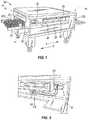
- FIG. 1is a perspective view of a conveyor oven in accordance with an embodiment of the present invention
- FIG. 2is a perspective view of a portion of the conveyor oven of FIG. 1 , in which a hinged oven access panel has been opened to reveal some of the internal workings of the oven;
- FIG. 3Ais a schematic illustration of an embodiment of the control system of the conveyor oven of FIG. 1 ;
- FIG. 3Bis an enlarged elevation view of an embodiment of the controls of the oven of FIG. 1 ;
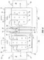
- FIG. 4is a diagrammatic representation of the tunnel of the oven of FIG. 1 , apportioned into two segments with independent temperature sensing and independent heat delivery means;
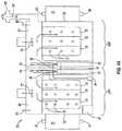
- FIG. 4Ais a diagrammatic representation of the tunnel of the oven of FIG. 1 , according to another embodiment
- FIGS. 5A-5Cinclude a diagrammatic representation of a pizza moving through the heated tunnel of the conveyor oven of FIG. 1 , with graphs showing changing BTU burner output and blower output as the pizza advances through the tunnel;
- FIG. 6is a diagrammatic representation of a single burner of a contiguous multiple burner configuration in accordance with an embodiment of the present invention.
- FIG. 6Aillustrates a venturi support disk of the burner of FIG. 6 ;
- FIG. 6Billustrates a flame retention member of the venturi tube of the burner of FIG. 6 ;
- FIGS. 7A and 7Bare perspective views of a pair of contiguous burners in accordance with an embodiment of the present invention.
- FIG. 8shows the distal ends of the outer tubes of the burners of FIGS. 7A-7B ;
- FIGS. 9A-9Dillustrate crossover openings between the contiguous burners of FIGS. 7A-7B ;
- FIG. 10illustrates an alternative dual contiguous burner configuration in accordance with an embodiment the present invention
- FIG. 11is a top plan view of selected elements of the oven of FIG. 1 ;
- FIG. 12is a flowchart illustrating an energy management mode for the conveyor oven of FIG. 1 ;
- FIG. 13is a flowchart illustrating an energy management mode for the conveyor oven of FIG. 1 ;
- FIG. 14is a flowchart illustrating an energy management mode for the conveyor oven of FIG. 1 ;
- FIG. 15is a flowchart illustrating a combination of the energy management modes illustrated in FIGS. 12 and 13 for the conveyor oven of FIG. 1 ;
- FIG. 16is a flowchart illustrating a combination of the energy management modes illustrated in FIGS. 12, 13, and 14 for the conveyor oven of FIG. 1 ;
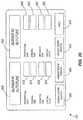
- FIG. 17is a schematic illustration of an alternative embodiment of the control system of the conveyor oven of FIG. 1 ;
- FIG. 18Aillustrates an embodiment of a main screen of an operator interface for the control system illustrated in FIG. 17 ;
- FIG. 18Billustrates another embodiment of a main screen of an operator interface for the control system illustrated in FIG. 17 ;
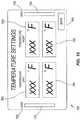
- FIG. 19illustrates an embodiment of a temperature setting screen of an operator interface for the control system illustrated in FIG. 17 ;
- FIG. 20illustrates an embodiment of a temperature tuning screen of an operator interface for the control system illustrated in FIG. 17 ;
- FIG. 21Aillustrates an embodiment of a belt tuning screen of an operator interface for the control system illustrated in FIG. 17 ;
- FIG. 21Billustrates another embodiment of a belt tuning screen of an operator interface for the control system illustrated in FIG. 17 ;
- FIG. 22illustrates an embodiment of a belt set-up screen of an operator interface for the control system illustrated in FIG. 17 ;
- FIGS. 23A, 23B, and 23Cillustrate an embodiment of energy savings mode set-up screens of an operator interface for the control system illustrated in FIG. 17 ;
- FIG. 24is an example of a food service floor plan showing a controller for a conveyor oven connected to several remote devices;
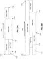
- FIGS. 25A and Bare examples of time lines of conveyor oven operation based on indications from one or more remote devices
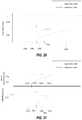
- FIG. 26is a graph of oven temperature as a function of time when a food item enters the heated tunnel of the conveyor oven of FIG. 1 ;
- FIG. 27is a timing diagram of the anticipatory temperature control of the conveyor oven of FIG. 1 ;
- FIG. 28is a flowchart showing temperature-based anticipatory temperature control in the conveyor oven shown in FIG. 1 ;
- FIG. 29is a graph of oven temperature as a function of time when food enters the heated tunnel of the conveyor oven of FIG. 1 with the anticipatory temperature control according to FIG. 28 ;
- FIG. 30is a flowchart showing current-based anticipatory temperature control in the conveyor oven of FIG. 1 ;
- FIG. 31is a graph of current provided to the heating element and oven temperature as functions of time when food enters the heated tunnel of the conveyor oven of FIG. 1 with the anticipatory temperature control according to FIG. 30 ;
- FIG. 32is a flowchart showing the selective application of the anticipatory temperature control where multiple food items are cooked in succession;
- FIG. 33is a flowchart illustrating a combination of the energy management modes for the conveyor oven of FIG. 1 ;
- FIG. 34is a flowchart showing another temperature-based anticipatory temperature control in the conveyor oven shown in FIG. 1 ;
- FIG. 35is a graph of oven temperature as a function of time when food enters the heated tunnel of the conveyor oven of FIG. 1 with the anticipatory temperature control according to FIG. 34 .
- connectionis used broadly and encompass direct and indirect connections, couplings, and mountings, and the terms “connected” and “coupled” and variations thereof are not restricted to physical or mechanical connections or couplings.
- phraseology and terminology used herein with reference to device or element orientationare only used to simplify description of the present invention, and do not alone indicate or imply that the device or element referred to must have a particular orientation.
- terms such as “first”, “second”, and “third”are used herein and in the appended claims for purposes of description and are not intended to indicate or imply relative importance or significance.
- FIG. 1shows a conveyor oven 20 having a conveyor 22 which runs through a heated tunnel 24 of the oven.
- the conveyor 22has a width generally corresponding to the width of the heated tunnel 24 and is designed to travel in direction A from left oven end 26 toward right oven end 28 or, alternatively in direction B, from right oven end 28 toward left oven end 26 .
- oven ends 26 and 28may serve respectively as the inlet and outlet of an oven with a rightwardly moving conveyor or as the outlet and inlet of an oven with a leftwardly moving conveyor.
- the conveyor 22can be implemented using conventional components and techniques such as those described in U.S. Pat. Nos. 5,277,105 and 6,481,433 and 6,655,373, the contents of which are incorporated herein by reference insofar as they relate to conveyor support, tracking, and drive systems and related methods.
- a chain link driveis housed within compartment 30 at the left end 26 of the oven.
- a food item 32 Rsuch as a raw pizza or sandwich (to be toasted) may be placed on the conveyor 22 of the ingoing left oven end 26 and removed from the conveyor 22 as fully baked food item 32 C (see FIG. 5C ) at the outgoing right oven end 28 .
- the speed at which the conveyor 22 movesis coordinated with the temperature in the heated tunnel 24 so that the emerging food item 32 C is properly baked, toasted, or cooked.
- a first conveyormay begin at left oven end 26 and travel at one speed to the center or other location of the oven 20 , while a second conveyor beginning at such a location and ending at the right oven end 28 may travel at a different speed.
- conveyors that are split longitudinallymay be used, so that one conveyor carries a product in direction A while the other conveyor carries a product in direction B, or so that two side-by-side conveyors carry product in parallel paths and in the same direction (A or B) through the oven 20 .
- a hinged door 34is provided on the front of the oven 20 , with a handle 35 and a heat resistant glass panel 36 , which permits a person operating the oven can view food item as it travels through the oven 20 .
- a stainless steel metal framesurrounds the oven opening and provides a support for a gasket of suitable material (not shown), so that when the hinged door 34 is in its closed position, it fits against and compresses the gasket to retain heat in the oven 20 .
- the operatormay open the door 34 by pulling on handle 35 to place a different product on the conveyor 22 if less than a full bake cycle is required to produce a fully cooked product.
- a sensor(not shown) is integrated into the hinged door 34 and configured to determine whether the hinged door 34 is opened or closed.
- the door sensorincludes a photo sensor that emits and detects an optical beam. The optical beam is detected by the photo sensor when the hinged door 34 is closed and is blocked when the hinged door 34 is open. In other embodiments, the operation is reversed such that the optical beam is blocked when the hinged door 34 is closed and is detected by the photo sensor when the door is open.
- the photo sensorsends a signal to a controller indicating the open or closed status of the hinged door 34 .
- the door sensorcan be implemented using other sensors, such as, for example, a mechanical switch or a light sensor that responds to the additional light introduced from the exterior of the conveyor oven when the hinged door 34 is open.
- a hinged oven access panel 38open as shown in FIG. 2 , provides access to internal components of the oven such as gas burners 100 , 150 and a blower 155 .
- the hinged oven access panel 38provides access to an electric heating element in electric oven embodiments.
- additional hot air blowers and ducts, their associated components, and/or the temperature sensors of the oven 20can be located within the area revealed by the opened access panel 38 .
- FIG. 3Ashows a schematic illustration of the control system for the oven 20 .
- a controller 42includes one or more displays 655 , and a control interface 660 ( FIG. 3B below).
- the control unit 42also includes a central processing unit (“CPU”) 650 .
- the CPU 650can be in the form of a microcontroller or programmable logic controller (PLC) with an associated memory unit in which software or a set of instructions is stored.
- PLCprogrammable logic controller
- the logic operations of controller 42are controlled by other mechanisms, such as, for example, a series of mechanical or solid-state relays.
- the CPU 650controls a plurality of devices including a heating element (including, for example, burners 60 , 62 or an electric heating element 63 , one or more blower switches, ignition switches and blowers, fuel valves, and flame sensing elements), one or more fans 72 , 74 , 87 (described in greater detail below), and one or more conveyors 22 .
- the CPU 650receives input from a plurality of sensors including one or more temperature sensors 80 , 82 and one or more photo sensors 79 , 81 and/or 83 , 85 (also described in greater detail below).
- the control unit 42includes one or more input/output jacks for connecting the CPU 650 to other, external equipment—such as, for example, a preexisting exhaust hood unit.
- the controller 42adjusts the internal temperature of the oven using a PID (proportional—integral—derivative) control module 55 (also described in greater detail below).
- PID control module 55is shown as a hardware component within controller 42 in FIG. 3A , the PID control module 55 can be implemented as software executed by CPU 650 .
- the CPU 650determines the internal temperature of the conveyor oven 20 using information from the temperature sensors 80 , 82 and provides the internal temperature information to the PID control module 55 .
- the PID control module 55calculates the amount of current needed by the electric heating element 63 to raise (or lower) the actual temperature of the oven toward the setpoint (or target) temperature.
- the CPU 650Based on information from the PID control module, the CPU 650 generates a command or signal to a power relay 58 (such as the Din-A-Mite® Power Controller manufactured by Watlow Electric Manufacturing Company) that that controls the thermal output of an electric heating element 63 .
- a power relay 58such as the Din-A-Mite® Power Controller manufactured by Watlow Electric Manufacturing Company
- the PID control module 55calculates an amount of fuel needed by the gas burner to raise the actual temperature toward the setpoint temperature and the CPU 650 generates a command or signal to an amplifier board or signal conditioner that controls a modulating fuel valve 59 that regulates the amount of fuel provided to the gas burner 60 , 62 .
- the PID control module 55calculates an amount of current that is approximately proportional to the difference between the actual temperature and the set-point temperature and instructs (or provides information to) the CPU 650 to increase the amount of current provided to the electric heating element 63 by the calculated amount. Similarly, if the actual temperature is higher than the set-point temperature, the PID control module 55 calculates an amount of current that is approximately proportional to the difference, and instructs the CPU 650 to decrease the current provided to the electric heating element 63 .
- the oven controlscan include the controller 42 (such as a Honeywell UDC 3300 controller) which may be programmed to control and monitor the baking process by pressing appropriate set-up and display buttons 42 a - 42 h while viewing alphanumeric display 46 , which will display process variables and setpoints including oven temperature, hot air blower speed, etc.
- a “heat on” indicatorcan be illuminated when a minimum threshold heat output is generated by the oven 20 under control of the controller 42 .
- the present temperature and/or the programmed setpoint temperaturemay be displayed. By simultaneously pressing selected keys in some embodiments, the value of the heat output with the heat on indicator in the “on” condition can be displayed.
- controller 42can be configured to enable a user to cycle through actual temperature display indicators to reveal the actual temperatures, setpoint temperature, and the heat on condition.
- the speed and direction of the conveyor 22can be set using buttons 48 a , 48 b , 50 a and 50 b and their associated displays 48 c and 50 c.
- the output display 46can be automatically locked in a default display when a service person or operator places the controller 42 in a service mode by pressing appropriate key(s).
- a failsafe conditioncan occur when any one of various tests fail, at which time a signal display (e.g., one or more flashing indicators) can be displayed, such as a signal display flashing alternately with a temperature display. For example, if the oven 20 has not reached 200° F. within 15 minutes after an initial power-up of the oven 20 , a message can be flashed on the display panel 46 indicating that controls need to be reset (e.g., power-cycled). As another example, if a temperature sensor fails to operate properly, the display 46 can flash “open”.
- the display 46can provide one or more prompts for servicing the oven 20 .
- Each additional press of a service tool keycan advance so that a service person can continually sequence through service prompts of a service mode.
- the service modecan be exited, for example, by either pressing an appropriate key or by pressing no key for a set period of time (e.g., sixty seconds). In either case, the system can be automatically returned to a normal state.
- a setpoint lock key 42 dcan automatically flash the temperature that has been selected for an operation of the oven 20 .
- this setpoint temperaturecan be increased or decreased by pressing either increment or decrement keys 42 f , 42 g .
- the degrees (° F. or ° C.) used for the promptscan be changed by pressing either the increment or decrement keys 42 f , 42 g .
- a selection of “F” or “C”can automatically change the units of all the display 46 to ° F. or ° C.
- an indicatorcan flash to indicate which display is chosen as the default display, which can be changed, for example, by pressing either the increment or decrement keys 42 f , 42 g.
- the oven 20is operated by: (1) turning a blower control 52 to an “ON” position to start a blower (described in greater detail below), (2) setting the temperature to a desired level using the controller 42 as described above, (3) turning a heat control 54 to an “ON” position to supply gas and to trigger ignition of the oven burner(s) (described in greater detail below), (4) turning a conveyor control 56 to an “ON” position to drive the conveyor 22 , and (5) after an appropriate pre-heat period, placing food items on the conveyor and beginning the baking process.
- Heat delivery systems for supplying heat to the tunnel 24are described in U.S. Pat. Nos. 5,277,105, 6,481,433 and 6,655,373, the disclosures of which are incorporated herein by reference insofar as they relate to heat delivery systems for ovens.
- These systemstypically include a heat source in the form of a single gas-fired burner (or other heat source) for heating a plenum.
- the burnercan be located at the front of the oven for heating a plenum located at the back of the oven.
- Blowersare typically provided to move heat in the plenum through passageways to metal fingers that open into the oven at appropriate spacings from the conveyor belt to deliver streams of hot air onto food items present on the conveyor, as discussed earlier.
- the heat sourceis cycled on and off as necessary by a controller responding to signals from temperature sensors (e.g., thermocouples) positioned, for example, at the inlet and outlet ends of the oven tunnel.
- temperature sensorse.g., thermocouples
- uniform heating from one end of the tunnel 24 to the otheris achieved by apportioning the tunnel 24 into two or more segments and by providing independent temperature sensing and independent delivery of heated air to each segment.
- Thisis shown diagrammatically in FIG. 4 and in an alternative embodiment shown in FIG. 4A , where the oven 20 has a pair of burners 60 and 62 with respective heating flames 64 and 66 supplying heat to respective independent plenums 68 and 70 associated with segments 20 A and 20 B of the oven 20 .
- the heat in plenums 68 and 70is blown into the two oven segments 20 A, 20 B by separate blower fans 72 and 74 through holes 75 and 77 in groupings of top fingers 76 and 78 (and through holes in corresponding groupings of bottom fingers, not shown) associated with the respective oven segments 20 A, 20 B.
- a number of different types of fans 72 , 74 , 87can be utilized for supplying heated air within the oven 20 and/or for removing exhaust from the oven 20 , and can be driven by any type of motor. As will be described in greater detail below, it is desirable in some embodiments to control the speed of any one or more of the fans 72 , 74 , 87 based at least in part upon one or more temperatures sensed within the oven 20 , one or more positions of food within, entering, or exiting the oven 20 , and/or the passage of one or more predetermined periods of time. To provide control over fan speed based upon any of these factors, the fans 72 , 74 , 87 can be driven by motors (not shown) coupled to and controlled by the controller 42 .
- the fans 72 , 74 , 87are driven by variable-speed motors coupled to and controlled by the controller 42 .
- Powercan be supplied to each variable-speed motor by, for example, respective inverters.
- each inverteris a variable-speed inverter supplying power to the motor at a frequency that is adjustable to control the speed of the motor and, therefore, the speed of the fan 72 , 74 , 87 .
- An example of such an inverteris inverter Model No. MD60 manufactured by Reliance Electric (Rockwell Automation, Inc.).
- the fans 72 , 74 , 87 described and illustrated hereincan be located anywhere with respect to the plenums 68 , 70 of the oven 20 , and can be used to pull and/or push air with respect to the plenums 68 , 70 and/or the tunnel 24 .
- one or more fans 87can be located anywhere in an exhaust duct or exhaust plenum of the conveyor oven 20 , in an exhaust hood 89 in fluid communication with the conveyor oven tunnel 24 , or in other locations in which the fans 87 are capable of moving air within the conveyor oven 20 as described herein.
- the conveyor oven 20includes an exhaust hood 89 for removing excess heated air from the tunnel 24 .
- the exhaust hood 89includes one or more fans 87 operated by the control unit 42 , and includes ducting from the heated tunnel to an exterior area (usually the exterior of the building). When activated, the fan(s) 87 dispel heated air from the tunnel 24 .
- the exhaust hood 89is integrated as part of the conveyor oven 20 (i.e., has a housing, frame, or other body in common with the conveyor oven 20 ). In other embodiments, the exhaust hood 89 is a separate unit not mechanically connected with the conveyor oven 20 , but still in fluid communication with the exhaust of the conveyor oven 20 .
- the exhaust fan(s) 87in either case, can be driven by variable-speed motors coupled to and controlled by the controller 42 , as described above. Power can be supplied to each variable-speed motor by, for example, respective inverters.
- each inverteris a variable-speed inverter supplying power to the motor at a frequency that is adjustable to control the speed of the motor and, therefore, the speed of the exhaust fan(s) 87 .
- An example of such an inverteris inverter Model No. MD60 manufactured by Reliance Electric (Rockwell Automation, Inc.).
- the conveyor oven 20is installed in a location where an exhaust hood 89 already exists, or in a location where a separate exhaust hood 89 is to be installed.
- the exhaust hood 89can be provided with a separate programmable or non-programmable controller and/or one or more user-manipulatable controls (e.g., buttons, dials, switches, and the like) to control operation of the exhaust hood 89 .
- Such controlcan include turning one or more fans 87 of the exhaust hood on or off, and changing the speed of such fans 87 .
- the conveyor oven 20can be connected to the exhaust hood 89 in these applications by appropriate ductwork extending from an exhaust outlet of the conveyor oven 20 to a plenum or other exhaust input of the exhaust hood 89 .
- the controller of the exhaust hood 89can be electrically connected for communication with the controller 42 of the conveyor oven 20 , thereby enabling the controller 42 of the conveyor oven 20 to control the fan(s) 87 of the exhaust hood 89 .
- the controller of the exhaust hood 89can be bypassed by connecting the controller 42 of the conveyor oven 20 directly to the fan(s) 87 of the exhaust hood 89 , thereby enabling direct control of the fan(s) 87 by the conveyor oven controller 42 .
- the inventorshave discovered that establishing control of one or more exhaust hood fans 87 by either type of electrical connection can result in significant energy savings, particularly when the fan(s) 87 of the exhaust hood 89 are operated as described herein in connection with the other conveyor oven fans 72 , 74 .
- the description herein regarding operation of any of either or both fans 72 , 74applies equally to one or more exhaust fans 87 of an exhaust hood 89 connected to or integral with the conveyor oven 20 .
- the temperatures in each of the oven segments 20 A, 20 Bcan be monitored by temperature sensors (e.g., thermocouples or other temperature sensing elements) 80 and 82 , which are shown in FIG. 4 as being mounted near the inlet end 26 and the outlet end 28 of the oven 20 .
- Either or both temperature sensors 80 , 82can be located in respective plenums 68 , 70 as shown in the figures.
- either or both temperature sensors 80 , 82are instead located within the chamber through which the conveyor 22 moves. Either or both sensors 80 , 82 can be positioned nearer the midpoints of the segments 20 A, 20 B or in other locations, if desired.
- one or more position sensors 79 , 81 and/or 83 , 85can be located to detect the position of a pizza on the conveyor 22 , and to thereby control one or more operations of the oven 20 as a result of such position detection (described in greater detail below).
- one or more gas output sensors(not shown) can be positioned to detect the amount of fuel supplied to the oven 20 .
- This informationcan be provided to the controller 42 in order to control one or more operations of the oven 20 , such as to turn a conveyor 22 and/or fan 72 , 74 , 87 on or off, and/or to adjust the speed of the conveyor 22 and/or fan 72 , 74 , 87 .
- FIGS. 5A-5Cincludes a diagrammatic representation of a pizza moving through the oven tunnel 24 below graphs showing the changing BTU output of the burners 60 , 62 and the corresponding blower output as the pizza advances through the tunnel 24 .
- a raw pizza 32 Ris shown in FIG. 5C resting on the conveyor 22 before the pizza enters the oven tunnel 24 .
- the oven 20has been heated to a desired temperature.
- the oven 20can detect the presence of a food item 32 R on the conveyor 22 by a position sensor 79 , 81 .
- the position sensor 79 , 81 in this embodimentis a photo sensor including an optical emitter 79 and an optical receiver 81 positioned on opposite sides of the conveyor.
- the optical emitter 79emits an optical beam toward optical receiver 81 .
- optical receiver 48detects the optical beam.
- the optical beam from the optical emitter 79is obstructed by the food item 32 R and optical receiver 81 does not detect the optical beam.
- a reflective sensorcan be implemented with an optical emitter and optical detector positioned on the same side of the conveyor.
- a reflector positioned on the other side of the conveyorreflects the optical beam when a food item is not present.
- an embodiment using a diffuse reflective sensoremits an optical beam and detects the light reflected off the food item when the food item is present.
- Other embodimentsmay include, for example, an infrared detector positioned to detect a food item 32 R having a reduced temperature on the conveyor 22 , a motion sensor positioned to detect motion of a food item 32 R upon the conveyor 22 , a mechanical sensor with an arm or button that physically contacts the food item 32 R on the conveyor, or any other sensor capable of detecting the presence of the food item 32 R on the conveyor 22 .
- the position sensor 79 , 81can be coupled to the controller 42 , and can send one or more signals to the controller 42 responsive to the detection of a food item 32 R (or lack thereof) on the conveyor 22 .
- the controller 42can be responsive to the position sensor 79 , 81 by increasing the BTU output of either or both burners 60 , 62 .
- the controller 42responds to the signal(s) from the position sensor 79 , 81 by increasing the BTU output of the burner 60 of the left tunnel segment 20 A, and can also respond to the signal(s) from the position sensor 79 , 81 by increasing the speed of any or all of the fans 72 , 74 , 87 . Either response can occur immediately or after a lag time, and can occur relatively abruptly or gradually.
- the controller 42can gradually increase the speed of both fans 72 , 74 and/or the exhaust fan 87 from a slow, relatively quiet standby level 71 to a full speed level 73 , thereby supplying additional heat to both segments 20 A and 20 B of the tunnel (although an increase supply of heat can instead be provided to only one of the segments 20 A, 20 B in other embodiments).
- the controller 42can respond to the signal(s) from the position sensor 79 , 81 by quickly increasing the BTU output of the burner 60 of the left tunnel segment 20 A, by gradually increasing the BTU output of the burner 60 as the food item 32 R enters the left tunnel segment 20 A, or by quickly or gradually increasing the BTU output of the burner 60 only after a set period of time permitting any or all of the fans 72 , 74 , 87 to increase in speed.
- the controller 42can respond to the signal(s) from the position sensor 79 , 81 by gradually increasing the BTU output of the burner 62 of the right tunnel segment 20 , by gradually or quickly increasing the BTU output of the burner 62 following a lag time (e.g., a predetermined period of time that can be independent or dependent upon the speed of the conveyor 22 ), or by changing the BTU output of the burner 62 in any other manner.
- a lag timee.g., a predetermined period of time that can be independent or dependent upon the speed of the conveyor 22
- the temperature sensor 80can be used to detect the presence of a food item 32 R on the conveyor 22 .
- the temperature sensor 80draws heat causing sensor 80 ( FIG. 4 ) to call for the controller 42 to supply additional gas to the burner 60 and/or to increase the speed of either or both fans 72 , 74 and/or the exhaust fan 87 .
- the controller 42can respond to detection of the raw pizza 32 R by the temperature sensor 80 in any of the manners described above with reference to the position sensor 79 , 81 .
- the position sensor 79 , 81 and the temperature sensor 80can be connected to the controller 42 in parallel, thereby enabling the controller 42 to change the BTU output of the burner 60 and/or the speed of either or both fans 72 , 74 and/or the exhaust fan 87 based upon signals received by the position sensor 79 , 81 or the temperature sensor 80 .
- the above-described fan controlgenerates a reduced amount of heat loss and fan noise from the oven tunnel 24 into the surrounding environment, and defines a load management setback of the oven 20 .
- the establishment of a quiet and reduced airflow standby state of the fan(s) 72 , 74 , 87is an advantage of the load management setback.
- the fans 72 , 74 in the illustrated embodimentare operated in tandem, in alternate embodiments they could be operated independently of one another (e.g., so that the fan speeds are increased from their slower steady state level on an independent “as-needed” basis).
- the fans 72 , 74 in the illustrated embodimentoperate at about 2900 RPM at full speed and at a level of about 1400 RPM when in the standby mode.
- the full speed and standby speedscan vary depending at least in part upon design constraints of the oven 20 , the food being cooked, etc.
- the standby mode of either or both fans 72 , 74can be faster or slower as desired, such as a 2100 RPM standby speed for both fans 72 , 74 .
- the pizzaAs a pizza advances to the right to position 32 ( 2 ), the pizza is now warmed. Therefore, less heat is drawn by the pizza, and the temperature in the first tunnel segment 20 A rises. In some embodiments, this temperature rise is detected by the temperature sensor 80 of the first tunnel segment 20 A, which can signal the controller 42 to reduce the supply of gas to the left burner 60 , thereby producing a reduction in BTU output as shown in FIG. 5B . In these and other embodiments, the controller 42 can be triggered to reduce the supply of gas to the left burner 60 by a position sensor positioned in or adjacent the first tunnel segment 20 A to detect when the pizza has advanced to a location in the first tunnel segment 20 A.
- the position sensorcan have any of the forms described above with reference to the position sensor 79 , 81 at or adjacent the entrance to the left tunnel segment 20 A.
- the lowered BTU output levelcan continue for any part or all of the remaining time that the pizza is in the first tunnel segment 20 A (e.g., all of such time as shown in the illustrated embodiment of FIG. 5B ).
- the pizzareaches the position 32 ( 3 ) shown in FIG. 5C , and then passes the midpoint of the tunnel 24 between the two segments 20 A, 20 B. Since the pizza has exited, and there is therefore no further significant perturbation to the heating environment in segment 20 A, the controller 42 can lower the gas supply (and therefore the BTU output) of the left burner 60 to a reduced steady state.
- This reductioncan be triggered by a threshold temperature change detected by the temperature sensor 80 in the first tunnel segment 20 A and/or by the temperature sensor 82 in the second tunnel segment 20 B.
- this reductioncan be triggered by one or more signals from a position sensor positioned to detect when the pizza has advanced to a location between the first and second tunnel segments 20 A, 20 B (or near such a location).
- the position sensorcan have any of the forms described above with reference to the position sensor 79 , 81 at or adjacent the entrance to the left tunnel segment 20 A.
- the right burner 62supplies heat to the second tunnel segment 20 B.
- the sensor 82 corresponding to the second tunnel segment 20 Bcan initially detect a spillover of heat from the first tunnel segment 20 A (i.e., as the pizza enters and is in the first part of the baking process in the first tunnel segment 20 A). Upon detection of sufficient spillover heat (e.g., when the sensor 82 detects that a threshold temperature has been reached), the sensor 82 can trigger the controller 42 to drop the initial BTU output of the right burner 62 . However, when the partially cooked pizza approaches the right tunnel segment 20 B, the pizza draws heat from the second tunnel segment environment.
- This heat drawcan also be detected by the sensor 82 of the second tunnel segment 20 B, which can trigger the controller 42 to supply additional gas to the burner 62 of the second tunnel segment 20 B.
- the BTU output of the right burner 62can increase as the pizza moves to and through positions 32 ( 4 ), 32 ( 5 ), and 32 ( 6 ).
- the reduction and increase of right burner BTU output just describedcan also or instead be triggered by one or more signals from one or more position sensors positioned in or adjacent the second tunnel segment 20 B to detect when the pizza has advanced to one or more locations within the oven 20 .
- the position sensor(s)can have any of the forms described above with reference to the position sensor 79 , 81 at or adjacent the entrance to the left tunnel segment 20 A.
- the temperature sensor 82 of the second tunnel segment 20 Bcan detect a rise in the tunnel temperature, and can trigger the controller 42 to reduce the output of the right burner 62 as shown in the BTU output graph of FIG. 5B .
- the resulting reduction in temperature in the second tunnel segment 20 Bcan also be detected by the temperature sensor 80 of the first tunnel segment 20 A due to heat spillover between the two tunnel segments 20 A, 20 B, and can trigger the controller 42 to increase the output of the left burner 60 to maintain the steady state temperature between the two oven segments 20 A, 20 B.
- the controller 42can automatically increase the output of the left burner 60 when the output of the right burner 62 is reduced (or near in time to such reduction of the right burner 62 ).
- the controller 42can also respond by returning the speed of the fans 72 , 74 and/or exhaust fan 87 to a standby state. This change in fan operation can take place relatively abruptly or gradually, and can take place immediately after a threshold temperature is detected by either or both sensors 80 , 82 or after a predetermined period of time.
- the increase of the left burner BTU output and the decrease in the right burner BTU output just describedcan also or instead be triggered by one or more signals from a position sensor positioned to detect when the food item (e.g., the pizza) is exiting or has exited the right tunnel segment 20 B.
- the oven 20 illustrated in FIG. 4has a position sensor 83 , 85 (comprising a light source 83 and a photocell 85 ) that is substantially the same as the position sensor 79 , 81 at the entrance to the left tunnel segment 20 A described above.
- the position sensor 83 , 85can have any of the forms described above with reference to the position sensor 79 , 81 at or adjacent the entrance to the left tunnel segment 20 A.
- the position sensor 83 , 85 and the temperature sensor 82can be connected to the controller 42 in parallel, thereby enabling the controller 42 to change the BTU output of the burner 62 and/or the speed of any or all of the fans 72 , 74 , 87 based upon signals received by the position sensor 83 , 85 or the temperature sensor 82 .
- the BTU output of either or both burners 60 , 62can be controlled by the controller 42 in any manner desired.
- the gas supply to either or both burners 60 , 62can be lowered or raised by the controller 42 relatively abruptly or gradually upon detection of threshold temperatures by either or both temperature sensors 80 , 82 , after a set period of time, and/or after sufficient movement of the food item is detected by a position sensor.
- the controller 42can control either or both blower fans 72 , 74 or the exhaust fan 87 based at least in part upon the temperature detected by a temperature sensor 80 , 82 , an amount of time elapsed following a change in power supply to a burner 60 , 62 , and/or the detection of a position of pizza or other food item on the conveyor 22 by a photo sensor 79 , 81 , 83 , 85 .
- the speed of either or both fans 72 , 74is increased after air driven by the fan(s) 72 , 74 has been sufficiently heated.
- the controller 42can control the BTU output of either or both burners 60 , 62 based at least in part upon the temperature detected by a temperature sensor 80 , 82 , an amount of time elapsed following a change in speed of a fan 72 , 74 , 87 and/or the detection of a position of pizza or other food item on the conveyor 22 by a photo sensor 79 , 81 , 83 , 85 .
- the BTU output of either or both burners 60 , 62is increased only after either or both fans 72 , 74 and/or the exhaust fan 87 are brought up to a threshold speed.
- the oven 20can include one or more temperature sensors 93 , 95 (e.g., thermocouples) coupled to the controller 42 and positioned near either or both burners 60 , 62 to detect the temperature of either or both flames 93 , 95 .
- a speed change of the fans 72 , 74 87can be delayed for a desired period of time in order to prevent undue cycling of the fans 72 , 74 , 87 as temperatures rise and fall within the tunnel 24 and as the BTU output of the burners 60 , 62 rise and fall.
- a relay 91 coupled to the temperature sensors 93 , 95is also coupled to the controller 42 , and cooperates with the controller 42 to reduce power to either or both fans 72 , 74 and/or the exhaust fan 87 in a manner as just described.
- a threshold valuee.g. 60% of maximum output in some embodiments
- the relay 91 and controller 42enter into a timed state.
- the threshold valuee.g., 60% of maximum output in some embodiments
- Either or both burners 60 , 62can be re-activated in some embodiments by detection of a sufficiently low threshold temperature by either of the tunnel segment temperature sensors 80 , 82 , by sufficient movement of a food item detected by any of the position sensors described above, after a set period of time has passed, and the like.
- the tendency of the fans 72 , 74 and/or the exhaust fan 87 to cyclee.g., between high and low speed levels, and in some cases between on and off states
- the fans 72 , 74 , 87can remain at a full speed level until a lowered BTU level is established for at least the set period of time, such as for five minutes in the illustrated embodiment.
- the BTU output of the burners 60 , 62 in some embodimentscan be reduced to a relatively low level (e.g., as low as a 5:1 air to gas ratio, in some cases).
- a relatively low levele.g., as low as a 5:1 air to gas ratio, in some cases.
- Relatively low (and relatively high) burner BTU outputcan generate problems associated with poor combustion.
- relatively low burner BTU outputcan generate incomplete combustion and flame lift-off.
- the controller 42 in some embodiments of the present inventionis adapted to turn gas to either or both burners 60 , 62 completely off in the event that either or both temperature sensors 80 , 82 detect that a low threshold temperature has been reached.
- the controller 42responds by turning off gas to the burner 60 , 62 associated with that temperature sensor 80 , 82 (either immediately or if a higher temperature is not detected after a set period of time).
- the supply of gas to the burner 60 , 62can be restored after a period of time and/or after the temperature sensor 80 , 82 detects a temperature below a lower predetermined threshold temperature.
- the burner 60 , 62can be cycled in order to avoid operating the burner 60 , 62 at a very low BTU output.
- two or more burners 60 , 62will always be on or off together.
- the controller 42can respond to a low threshold temperature by turning off the supply of gas to both burners 60 , 62 , and can restore the supply of gas to both burners 60 , 62 after a period of time and/or after the temperature sensor 80 , 82 detects that a lower threshold temperature has been reached.
- the controller 42responds by turning off gas to the burner 60 , 62 associated with that temperature sensor 80 , 82 (either immediately or if a lower temperature is not detected after a set period of time).
- the supply of gas to the burner 60 , 62can be restored after a period of time and/or after the temperature sensor 80 , 82 detects a temperature below the low threshold temperature or a sufficient drop in temperature. In this manner, the burner 60 , 62 can be cycled in order to avoid operating the burner 60 , 62 at a very high BTU output.
- the controller 42can respond to a high threshold temperature by turning off the supply of gas to both burners 60 , 62 , and can restore the supply of gas to both burners 60 , 62 after a period of time and/or after the temperature sensor 80 , 82 detects a temperature below the low threshold temperature or an otherwise sufficient drop in temperature.
- tunnel segments 20 A, 20 Bare used in the illustrated embodiment, more than two tunnel segments can be used in other embodiments, each such alternative embodiment having one or more tunnel segments with any combination of the elements and features described above with reference to the illustrated embodiment.
- the illustrated embodimentuses separate burners 60 , 62 for each tunnel segment 20 A, 20 B. In other embodiments, it is possible to achieve the desired segment-specific heating using a single burner and conventional structure and devices to direct heat to each segment independently in response to signals from temperature sensors associated with each of the segments.
- the embodiments discussed aboveinclude gas burners, other heating elements and devices can instead or also be used (e.g., one or more electric heating elements).
- heating elementsrefers to gas burners, electric heating elements, microwave generating devices, and all alternative heating elements and devices.
- Components of the oven 20 that can be controlled to provide energy savingsmay include either or both burners 60 and 62 , either or both fans 72 and 74 , one or more exhaust fans 87 , and/or the conveyor 22 .
- Saving energy with the burners 60 and 62may be achieved by lowering the temperature threshold in one or both of the plenums 68 and 70 that the burners 60 and 62 heat. This lower threshold can cause one or both of the burners 60 and 62 to be on less often, or to operate at a lower output, resulting in energy savings. Additionally, one or both of the burners 60 and 62 may be turned off completely.
- Saving energy with the burner fans 72 , 74 and the exhaust fans 87may be achieved by reducing the speed or RPMs of one or more of the fans which can require less power and, therefore, save energy. Additionally, one or more of the fans may be turned off completely.
- Saving energy with the conveyor 22may be achieved by slowing down or turning off the conveyor 22 .
- plenum temperature, fan speed, and conveyor speedmay be any number of values between a minimum and a maximum, it may be more practical to choose one or more settings in the range between each minimum and maximum.
- Energy management strategiesmay include controlling any one or more of the burners 60 , 62 , blower fans 72 , 74 , exhaust fans 87 , and conveyor 22 of the oven 20 individually or in combination and/or controlling such components in the different segments of the oven 20 individually or in combination.
- Energy management events which cause one or more energy management strategies described herein to executemay be triggered by one or more actions, alone or in combination, including a predetermined amount of elapsed time, feedback from one or more temperature sensors, feedback from one or more position sensors, feedback from the door sensor, feedback from one or more motion detectors, and the like.
- FIG. 12illustrates a process for an energy management mode that can be utilized for a conveyor oven, such as the oven 20 of FIG. 4 .
- FIGS. 12-15refer to the detection and baking of a pizza, the process can be used to cook other food items similarly.
- the controller 42can check for the presence of a pizza on conveyor 22 .
- a pizzacan be detected in any of the manners described herein, such as by one or more optical sensors 79 and 81 .
- a timercan be reset, either or both of the fans 72 and 74 and/or the exhaust fan 87 can be set to a higher speed, and/or either or both of the burners 60 , 62 can be set to a higher level to raise the temperature in one or both of the plenums 68 , 70 to a higher level (steps 305 , 310 , and 315 ). If no pizza is detected by the sensors 79 and 81 (step 300 ), the controller 42 can check a timer to determine the period of time since the last pizza was put on the conveyor 22 (step 320 ).
- the operation of the oven 20can remain unchanged and the controller 42 can continue to check for the presence of a pizza (step 300 ). If the timer exceeds the predetermined threshold, the controller 42 can go into an energy saving mode. In this energy saving mode, either or both fans 72 and 74 and/or the exhaust fan 87 can be set to a low speed and the temperature can be set to a low value (steps 325 and 330 ). The controller 42 can then continue to check for the presence of a pizza on the conveyor 22 (step 300 ). The controller 42 can remain in this energy saving mode until a pizza is detected on the conveyor 22 at step 300 .
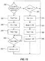
- FIG. 13illustrates another embodiment of a process for an energy management mode that can be utilized for a conveyor oven, such as the conveyor oven 20 of FIG. 4 .
- the controller 42can check for the presence of a pizza on conveyor 22 .
- a pizzacan be detected in any of the manners described herein, such as by one or more optical sensors 79 and 81 .
- a timercan be reset, one or more of the fans (blower fans 72 , 74 or the exhaust fans 87 ) can be set to a higher speed, and/or either or both of the burners 60 , 62 can be set to a higher level to raise the temperature in one or both of the plenums 68 , 70 to a higher level (steps 340 , 345 , and 350 ).
- the oven temperaturecan be relatively low (e.g., if the oven has been in an energy management mode), it may be necessary to wait until the temperatures in the plenums 68 and 70 reach levels that will result in temperatures satisfactory for baking when the pizza arrives in the respective plenums before allowing the pizza on conveyor 22 to enter the oven 20 . Therefore, at step 355 , the controller 42 can wait until the temperatures of the oven 20 reach their thresholds.
- the conveyor 22can start (step 360 ) and the pizza can enter the oven 20 and bake. If no pizza is detected by the sensors 79 and 81 (step 335 ), the controller 42 can check a timer to determine the period of time since the last pizza was put on the conveyor 22 (step 365 ). If the timer is less than a predetermined threshold, the operation of the oven 20 can remain unchanged and the controller 42 can continue to check for the presence of a pizza (step 335 ). If the timer exceeds the predetermined threshold, the controller 42 can enter an energy saving mode.
- one or more fanscan be set to a low speed (step 370 ), the burner 62 for either or both plenums 68 , 70 can be turned off (e.g., the back plenum 70 can be turned off as indicated at step 375 ), and the temperature in the first plenum 68 can be set to a lower level (step 380 ).
- the conveyor 22can also be turned off (step 385 ).
- the controller 42can then continue to check for the presence of a pizza on the conveyor 22 (step 335 ). The controller 42 can remain in this energy saving mode until a pizza is detected on the conveyor 22 at step 335 .
- FIG. 14illustrates another embodiment of a process for an energy management mode that can be utilized for a conveyor oven, such as the conveyor oven 20 of FIG. 4 .
- the controller 42can check for the presence of a pizza on conveyor 22 .
- a pizzacan be detected in any of the manners described herein, such as by one or more optical sensors 79 and 81 .
- a timercan be reset, one or more of the fans (blower fans 72 , 74 or the exhaust fans 87 ) can be set to a higher speed, and/or either or both of the burners 60 , 62 can be set to a higher level to raise the temperature in one or both of the plenums 68 , 70 to a higher level (steps 405 , 410 , and 415 ).
- the oven temperaturecan be relatively low (e.g., if the oven has been in an energy management mode), it may be necessary to wait until the temperatures in the plenums 68 and 70 reach levels that will result in temperatures satisfactory for baking when the pizza arrives in the respective plenums before allowing the pizza on conveyor 22 to enter the oven 20 . Therefore, at step 420 , the controller 42 can wait until the temperatures of the oven 20 reach their thresholds.
- the conveyor 22can start (step 425 ) and the pizza can enter the oven 20 and bake. If no pizza is detected by the sensors 79 and 81 (step 400 ), the controller 42 can check a timer to determine the period of time since the last pizza was put on the conveyor 22 (step 420 ). If the timer is less than a predetermined threshold, the operation of the oven 20 can remain unchanged and the controller 42 can continue to check for the presence of a pizza (step 400 ). If the timer exceeds the predetermined threshold, the controller 42 can go into an energy saving mode.
- one or more fanscan be turned off (step 435 ), either or both burners 60 and 62 can be turned off (step 440 ), and the conveyor 22 can be turned off (step 445 ).
- the controller 42can then continue to check for the presence of a pizza on the conveyor 22 (step 400 ).
- the controller 42can remain in this energy saving mode until a pizza is detected on the conveyor 22 at step 400 .
- FIG. 15illustrates another embodiment of a process for an energy management mode that can be utilized for a conveyor oven, such as the conveyor oven 20 of FIG. 4 .
- the process illustrated in FIG. 15combines much of the processes illustrated in FIGS. 12 and 13 .
- the controller 42can check for the presence of a pizza on conveyor 22 .
- a pizzacan be detected in any of the manners described herein, such as by one or more optical sensors 79 and 81 . If a pizza is detected, a timer can be reset, one or more fans (blower fans 72 , 74 or the exhaust fans 87 ) can be set to a high speed, and the temperature can be set to a high level (steps 455 , 460 , and 465 ).
- the controller 42can check a timer to determine the period of time since the last pizza was put on the conveyor 22 (step 470 ). If the timer is less than a first predetermined threshold, the operation of the oven 20 can remain unchanged and the controller 42 can continue to check for the presence of a pizza (step 450 ). If the timer exceeds the first predetermined threshold, the controller 42 can check the timer to determine if it exceeds a second predetermined threshold (step 475 ). The second predetermined threshold is a period of time that is longer than the first predetermined threshold. If the timer does not exceed the second predetermined threshold, the controller 42 can enter a first energy saving mode.
- one or more fanscan be set to a low speed and the temperature can be set to a low value (steps 480 and 485 ).
- the controller 42can then continue to check for the presence of a pizza on the conveyor 22 (step 450 ).
- the controller 42can remain in this first energy saving mode until a pizza is detected on the conveyor 22 at step 450 or until the threshold period of time since the last pizza was detected on the conveyor 22 (e.g., until the second predetermined threshold of the timer is exceeded). If, at step 475 , the timer exceeds the second predetermined threshold, the controller 42 can enter a second energy saving mode.
- either or both burners 60 , 62can be turned off (e.g., the burner 62 for the back plenum 70 can be turned off as indicated at step 490 ), and the conveyor 22 can be turned off (step 495 ).
- the controller 42can then continue to check for the presence of a pizza on the conveyor 22 (step 500 ).
- the controller 42can remain in this second energy saving mode until a pizza is detected on the conveyor 22 at step 500 . If a pizza is detected at step 500 , the timer can be reset, one or more fans (blower fans 72 , 74 or the exhaust fans 87 ) can be set to a high speed, and the temperature can be set to a high level (steps 505 , 510 , and 515 ).
- the oven temperaturecan be relatively low (e.g., if the oven has been in an energy management mode), it may be necessary to wait until the temperatures in the plenums 68 and 70 reach levels that will result in temperatures satisfactory for baking when the pizza arrives in the respective plenums before allowing the pizza on conveyor 22 to enter the oven 20 . Therefore, at step 520 , the controller 42 can wait until the temperature(s) of the oven 20 reach their threshold(s). Once the temperatures of the oven 20 reach their thresholds, the conveyor 22 can start (step 525 ) and the pizza can enter the oven 20 and bake. The controller 42 can then exit the energy saving modes and continue checking for pizzas at step 450 .
- FIG. 16illustrates another embodiment of a process for an energy management mode that can be utilized for a conveyor oven, such as the conveyor oven 20 of FIG. 4 .
- the process illustrated in FIG. 16combines much of the processes illustrated in FIGS. 12, 13, and 14 .
- the controller 42can check for the presence of a pizza on conveyor 22 .
- a pizzacan be detected in any of the manners described herein, such as by one or more optical sensors 79 and 81 . If a pizza is detected, a timer can be reset, one or more fans (blower fans 72 , 74 or the exhaust fans 87 ) can be set to a high speed, and the temperature can be set to a high level (steps 555 , 560 , and 565 ).
- the controller 42can check a timer to determine the period of time since the last pizza was put on the conveyor 22 (step 570 ). If the timer is less than a first predetermined threshold, the operation of the oven 20 can remain unchanged and the controller 42 can continue to check for the presence of a pizza (step 550 ). If the timer exceeds the first predetermined threshold, the controller 42 can check the timer to determine if it exceeds a second predetermined threshold (step 575 ). The second predetermined threshold is a period of time that is longer than the first predetermined threshold. If the timer does not exceed the second predetermined threshold, the controller 42 can enter a first energy saving mode.
- one or more fanscan be set to a low speed, and the temperature can be set to a low value (steps 580 and 585 ).
- the controller 42can then continue to check for the presence of a pizza on the conveyor 22 (step 550 ).
- the controller 42can remain in this first energy saving mode until a pizza is detected on the conveyor 22 at step 550 or until the threshold period of time since the last pizza has been detected on the conveyor 22 (e.g., until the second predetermined threshold of the timer is exceeded). If, at step 575 , the timer exceeds the second predetermined threshold, the controller 42 can enter a second energy saving mode.
- either or both burners 60 , 62can be turned off (e.g., the burner 62 for the back plenum 70 , can be turned off as indicated at step 590 ), and the conveyor 22 can be turned off (step 595 ).
- the controller 42can then continue to check for the presence of a pizza on the conveyor 22 (step 600 ). If a pizza is detected at step 600 , the timer can be reset to zero, one or more fans (blower fans 72 , 74 or the exhaust fans 87 ) can be set to a high speed, and the temperature can be set to a high level (steps 605 , 610 , and 615 ).
- the oven temperaturecan be relatively low (e.g., if the oven has been in an energy management mode), it may be necessary to wait until the temperatures in the plenums 68 and 70 reach levels that will result in temperatures satisfactory for baking when the pizza arrives in the respective plenums before allowing the pizza on conveyor 22 to enter the oven 20 . Therefore, at step 620 , the controller 42 can wait until the temperature(s) of the oven 20 reach their threshold(s). Once the temperatures of the oven 20 reach their thresholds, the conveyor 22 can start (step 625 ) and the pizza can enter the oven 20 and bake. The controller 42 can then exit the energy saving modes and continue checking for pizzas at step 550 .
- the controller 42can check a timer to determine the period of time since the last pizza was placed on the conveyor 22 (step 630 ). If the timer is less than a third predetermined threshold, the operation of the oven 20 can remain in the second energy saving mode, and the controller 42 can continue to check for the presence of a pizza (step 600 ).
- the third predetermined thresholdis a period of time that is longer than the second predetermined threshold. If the timer exceeds the third predetermined threshold, the controller 42 can enter a third energy saving mode.
- one or more fanscan be turned off (step 635 ) and the first burner 60 can be turned off (step 640 ).
- the controller 42can then continue to check for the presence of a pizza on the conveyor 22 (step 600 ).
- the oven 20may remain in the third energy savings mode until a pizza is detected at step 600 . Once a pizza is detected at step 600 , processing continues at step 605 as previously described.
- FIG. 33illustrates another embodiment of a process for an energy management mode that can be utilized for a conveyor oven, such as the conveyor oven 20 of FIG. 4 .
- the controller 42checks for the presence of a pizza on conveyor 22 . If a pizza is detected, the timer is reset, both blower fans 72 and 74 and exhaust fan 87 are set to a high speed, the temperature is set to a high level, and the conveyor remains turned on (steps 1306 , 1308 , 1310 , and 1312 ). If no pizza is detected by the sensors 79 and 81 (step 1304 ), the controller 42 checks the timer to determine the period of time since the last pizza was put on the conveyor 22 and compares that period of time to a threshold A (step 1314 ). If the timer is less than the threshold A, the operation of the oven 20 remains unchanged and the controller 42 continues to check for the presence of a pizza (step 1304 ).
- the controller 42checks the timer to determine if it exceeds a second threshold B (step 1316 ). If the timer exceeds threshold A, but does not exceed threshold B, the controller 42 enters a first energy saving mode. In the first energy saving mode, all of the fans (blower fans 72 , 74 or the exhaust fans 87 ) are set to operate at half speed (step 1318 ), but the temperature is not reduced (step 1320 ). The controller 42 continues to operate (step 1322 ) and the controller 42 continues to check for the presence of a pizza on the conveyor (step 1304 ).
- the controllercompares the timer to a third threshold C (step 1324 ). If the timer exceeds thresholds A and B, but does not yet exceed threshold C, the controller 42 enters a second energy saving mode. In the second energy saving mode, all of the fans (blower fans 72 , 74 or the exhaust fans 87 ) are set to operate at half speed (step 1326 ). The power supplied to the electric burners is reduced, thereby lowering the internal temperature of the oven (step 1328 ). The conveyor is turned off in this second energy saving mode (step 1330 ). The controller 42 continues to check for the presence of a pizza on the conveyor (step 1304 ).
- the controllercompares the timer to a fourth threshold D. If the timer exceeds thresholds A, B, and C, but does not yet exceed threshold D, the controller 42 enters a third energy saving mode. In the third energy saving mode, the fans, burners, and conveyor are all turned off (steps 1334 , 1336 , and 1338 ). The controller 42 continues to check for the presence of a pizza on the conveyor (step 1304 ).
- the controllerenters a fourth energy saving mode.
- the ovenis completely turned off and the fans, burners, and conveyor are powered down (steps 1340 , 1342 , and 1344 ). Furthermore, the controller 42 no longer continues to check for the presence of a pizza on the conveyor (step 1304 ). After entering the fourth energy saving mode, the oven must be restarted manually (step 1346 ).
- Embodiments of three energy savings modeshave been illustrated along with two combinations of the illustrated energy savings modes. Further embodiments can include, for example, combining the embodiments of FIGS. 12 and 14 or FIGS. 13 and 14 . Further, other methods of controlling these and other components of the conveyor oven can be utilized to create additional energy saving modes and combinations thereof.
- the energy saving modeis initiated when no food item is detected by the sensors 79 and 80 for a period of time longer than a predetermined threshold.
- the thresholdis set to be slightly longer than the amount of time required for the conveyor to transport the food item from the position where it is detected by sensors 79 and 80 to the exit of the heated tunnel 24 .
- the thresholdmay be set to the conveyor time plus one minute.
- the controller 42is also brought out of the energy saving mode, as described in reference to FIGS. 12-16 , when the hinged door 34 is opened.
- the controller 42uses the same threshold timing regardless of what method brings the controller out of the energy saving mode.
- the controller 42uses a truncated (or, more broadly, a modified) timing cycle when the controller 42 is brought out of the energy saving mode in response to the hinged door 34 being opened.
- a food item that is placed on the conveyor through the hinged door 34will exit the oven in less time than a food item placed on the conveyor at the opening.
- a shorter thresholdis used to determine when the controller 42 will reenter the energy saving mode.
- the shorter thresholdcorresponds to the shorter cooking time. In some embodiments, the shorter threshold is equal to 80% of the full threshold.
- one or more remote input devicescan provide an indication to the controller 42 that food item (e.g., a pizza) needs to be baked.
- Such remote input devicescan change the operational state of the oven 20 , such as by providing trigger mechanisms (other than those described elsewhere herein) to prepare the oven for cooking.
- Remote input devicescan include one or more push buttons, switches, knobs, keypads, operator interfaces, cash registers, or other user manipulatable devices, one or more sensors (e.g., pressure sensors, limit switches, optical sensors), a computer, and the like.
- some remote input devicesare only capable of limited functionality (e.g., bringing an oven out of an energy saving mode).
- remote input devicessuch as, for example, a cash register or a desktop computer
- other remote input devicesare capable of more extensive control functionality (e.g., increasing the set-point temperature of the oven, controlling the blower fans, adjusting the conveyor speed, etc.) when connected to the controller 42 .
- the control functionality of the remote input deviceis the same as the local controller 42 .
- the remote input deviceis capable of executing a different set of operations.
- the set of operations that can be executed by the remote input devicemay include some or all of the operations that can be executed by the local interface of controller 42 .
- the remote input deviceincludes a remote display unit that displays operating information received from the controller 42 .
- Such informationmay include, for example, oven temperature, energy mode status, location of a pizza on conveyor, etc.
- the remote input devicecan communicate with the controller 42 in any suitable manner, including a hard-wired connection, a wireless connection, an internet connection, and any combination of such connections.
- FIG. 24illustrates an exemplary layout of a kitchen 1000 for cooking and serving pizzas.
- a counter 1005can include one or more cash registers 1010 for taking customer orders.
- the kitchen 1000can include a refrigerator 1015 , a preparation table 1020 , a final preparation table 1030 , and/or any number of other food preparation and cooking stations and equipment.
- Other examples of such cooking stations and equipmentinclude walk-in coolers, sinks, racks, food processing equipment (e.g., mixers, grills, and the like), and the like.
- One or more remote devicescan be associated with any of such cooking stations or equipment, and can provide indication(s) that food item needs to be prepared by the conveyor oven 20 .
- a switch or sensor of the refrigerator 1015can detect when the door of the refrigerator 1015 has been opened, and can communicate with the controller 42 via link 1040 .
- a switch or sensor of the preparation table 1020can detect that food item is being made (e.g., by detecting the weight of food item placed upon the preparation table, optically detecting the presence of such food item, and the like), and can communicate with the controller via link 1045 .
- one or more cash registers 1010can inform the controller 42 via links 1050 and 1055 when a customer has ordered a pizza.
- the conveyor oven 20can be provided with one or more proximity sensors adapted to detect the presence of a cooking element (e.g., a cooking pan, tray, container, and the like) within a range of distance from such sensors, and can communicate with the controller via a link.
- the sensorcan be an RFID sensor, an LED sensor, and the like, wherein the cooking element is adapted to be recognized by the sensor, such as by being provided with an antenna on or embedded within the cooking element.
- Other types of remote devicescan be used in place of or in addition to those just described to inform the controller 42 that food item (e.g., one or more pizzas) needs to be cooked, thereby enabling the controller 42 to change the operational state of the oven 20 accordingly.
- the controller 42receives an indication from a remote device that a food item needs to be cooked (e.g., that a pizza ordered by a customer at a cash register will need to be cooked).
- the controller 42can immediately exit any energy savings mode it is in and enter an operating mode (e.g., a baking mode) where the conveyor 22 is turned on.
- the speed of one or more fans 72 , 74 and/or the exhaust fan 87can be increased and/or the heat output of one or more heating elements 60 , 62 can be increased in the operating mode of the oven 20 .
- the controller 42may keep the oven 20 in an energy saving mode for a period of time before entering the operating mode. The period of time the controller 42 keeps the oven 20 in the energy saving mode can be determined based at least in part upon the temperature of the oven 20 and/or a length of time until baking is to begin.
- the controller 42can detect a temperature of the oven 20 and can compare the temperature of the oven 20 to a desired cooking temperature. The controller 42 can then calculate the length of time (or use a look-up table to determine the length of time) the oven 20 needs to heat up from the present temperature in the oven 20 to the desired cooking temperature. The controller 42 can also know the amount of time from when the controller 42 receives the indication from the remote device until the food item is actually ready to be cooked (e.g., the preparation time).
- the controller 42can delay heating the oven 20 , such as until the remaining preparation time equals the amount of time needed to heat the oven 20 to the desired cooking temperature.
- the controller 42can delay heating the oven 20 based at least in part upon a known time by which the food item must be delivered or a desired cooking completion time.
- the time to deliverycan be based on a time of day (e.g., shorter during lunch and longer during dinner) or a variable time (e.g., the length of time until a delivery person will be available to deliver the food item).
- the cooking completion timecan be based upon an anticipated dining rush or other event.
- the controller 42can know the length of time the oven 20 needs to reach the baking temperature based at least in part upon the present temperature of the oven 20 as discussed above.
- the controller 42can automatically cause the oven 20 to enter or return to an energy saving mode. This process can be delayed for a predetermined period of time in order to prevent unnecessary cycling of the oven 20 , can be overridden based upon an indication of additional food item to be cooked (e.g., an indication from a remote device as described above), or can be overridden based upon a reduction in oven demand (e.g., when the rate of food item to be cooked falls to a predetermined threshold).
- an indication of additional food item to be cookede.g., an indication from a remote device as described above
- a reduction in oven demande.g., when the rate of food item to be cooked falls to a predetermined threshold.
- FIGS. 25A and Billustrate exemplary time lines for the operations described above.
- the controller 42receives an indication from a remote device that a pizza needs to be cooked at 1100 .
- the controller 42can then determine when the pizza will be ready to be placed on the conveyor 22 to be cooked ( 1105 ).
- the controller 42knows the preparation time of the pizza (the difference between 1105 and 1100 in FIG. 25A ), and can determine when to exit an energy-savings mode and to enter a heating mode ( 1110 ) by subtracting the heating time from the preparation time to arrive at the baking mode time ( 1110 ).
- the pizzathen finishes baking at 1115 and is ready for delivery, following final preparation at 1120 .
- FIG. 25Billustrates an exemplary time line for the operation of an oven 20 when the time to delivery 1120 is greater than the total time needed to prepare and cook a pizza.
- the controllerreceives (at 1100 ) an indication from a remote device that a pizza needs to be cooked.
- the controller 42can know the delivery time 1120 .
- the controller 42can work backward from the delivery time ( 1120 ) to determine the time to start heating the oven ( 1110 ) by subtracting the final preparation time (the difference between 1120 and 1115 ), the baking time (the difference between 1115 and 1105 ), and the heating time (the difference between 1105 and 1110 ), wherein the heating time can be calculated based upon the difference between the temperature of the oven and the desired baking temperature.
- the controller 42can enter an energy saving mode immediately at 1115 , provided a remote device has not indicated that another pizza needs to be cooked.
- the controller 42can also attempt to maximize the energy savings by setting a target temperature of the oven 20 , during an energy saving mode, such that the heating time is equal to the difference between the time an indication that a pizza needs to be cooked is received from a remote device ( 1100 ) and the time baking is to begin ( 1105 ).
- This target temperaturecan add time (indicated by 1125 ) to the heating time.
- the controller 42can receive one or more indications from a remote device to change oven operation based upon an anticipated demand for cooked food item.
- the indication(s)can turn the oven 20 on, can increase the heat output of one or more heating elements 60 , 62 , and/or can increase the speed of one or more fans 70 , 72 , 87 .
- different portions of the oven 20can be activated or de-activated in order to increase or decrease the cooking capacity of the oven 20 based upon the anticipated demand for cooked food item.
- Information reflecting the anticipated demand for cooked food itemcan also be received from the remote device(s), and can include data representing a quantity of food items to be cooked and/or a rate of food orders received).
- an oven 20can have two or more conveyors 22 for moving food item through the oven 20 .
- the conveyors 22can be stacked, can be side-by-side, or can have any other configuration described herein.
- a first conveyor 22in which two adjacent conveyors 22 of the same or different width run in parallel, can be operated independently of a second conveyor 22 , such as by moving faster or slower than the second conveyor, in a direction opposite the second conveyor, and the like.
- Feedback regarding either or both conveyors 22e.g., speed, temperature, and the like
- the remote devicecan indicate to the controller 42 a quantity of pizzas that need to be cooked.
- the controller 42can then determine if the first conveyor can cook the quantity of pizzas within a desired time. If the first conveyor cannot meet the demand, the controller 42 can cause the oven 20 to exit an energy saving mode (e.g., a mode in which the heating elements and/or fans associated with less than all conveyors are in an operating mode).
- an energy saving modee.g., a mode in which the heating elements and/or fans associated with less than all conveyors are in an operating mode.
- the controller 42can put one or more other conveyors into an operating mode or a stand-by mode in which such other conveyor(s) are heated to a level above the energy savings mode but less than the baking temperature.
- an oven 20can still cook food items while in one or more energy savings modes.
- one or more conveyors of a multiple-conveyor ovencan enter an energy saving mode while still being able to cook food items on one or more other conveyors of the oven.
- a conveyor oven 20 in a period of low demandcan operate with significantly less heat and/or fan output while still cooking food items, such as by slowing the conveyor 22 without significantly lengthening cooking time.
- the controller 42can determine the amount of time necessary to heat the oven 20 to the desired cooking temperature and can use the cooking time, final preparation time, and the initial preparation time to calculate a time when a pizza will be ready. The controller 42 can then provide this time to a display to inform an operator of the length of time necessary to prepare and cook the pizza.
- FIG. 6illustrates a single burner of a contiguous multiple burner configuration which has been found to be particularly useful.
- This burner 100comprises a housing (e.g., an outer tube 102 as shown in the illustrated embodiment) attached to a mounting plate 104 which closes off the proximal end of the outer tube 102 .
- the outer tube 102can have any shape desired, and in some embodiments has a relatively elongated shape as shown in the illustrated embodiment.
- a smaller diameter venturi tube 106is located within the outer tube 102 and has open distal and proximal ends 107 , 112 .
- the venturi tube 106can be generally centered with its longitudinal axis along the longitudinal axis of the outer tube 102 , although non-concentric relationships between the venturi tube 106 and the outer tube 102 can instead be employed.
- the venturi tube 106is secured in place near its distal end 107 by a venturi support 108 encircling the venturi tube 106 and secured within the inside diameter 109 of the outer tube 102 .
- a section 111 of the distal end 107 of the venturi tube 106extends beyond the venturi support 108 .
- a gas orifice 110can be located in the mounting plate 104 , and can be spaced from the proximal open end 112 of the venturi tube 106 .
- the gas orifice 110can be centered or substantially centered with respect to the open proximal end 112 of the venturi tube 106 , although other non-centered relationships between the venturi tube 106 and the gas orifice 110 are possible.
- the open proximal end 112 of the venturi tube 106receives pressurized gas from the gas orifice 110 , and serves as a primary air inlet to admit a flow of air 115 into the venturi tube 106 .
- aircan enter the proximal end 112 of the venturi tube 106 through apertures or gaps in the end of the venturi tube 106 , through one or more conduits coupled to the venturi tube 106 , or in any other manner.
- powered airis supplied to that portion of the outer tube 102 below the venturi support 108 .
- a powered air supplycan be coupled to the outer tube 102 in the illustrated embodiment via a conduit 113 leading to the outer tube 102 .
- the venturi support 108can have any shape adapted to support the venturi tube 106 and/or to at least partially separate an interior portion of the outer tube 102 from a burn region 116 opposite the proximal end 112 of the venturi tube 106 .
- the venturi support 108is substantially disc shaped (e.g., see FIG. 6A ).
- the venturi support 108can have an opening 117 (e.g., a central circular opening 117 as shown in FIG. 6A ) which fits about the circumference of the venturi tube 106 .
- one or more aperturescan be defined within the venturi support 108 , and in some cases can be defined between the venturi support 108 and the outer tube 102 and/or the venturi tube 106 .
- the venturi support 108has edges 119 and 121 that partially define open gaps 123 and 125 between the circumference of the venturi support 108 and the inside diameter 109 of the outer tube 102 .
- These gaps 123 , 125can admit secondary air to the burn region 116 opposite the proximal end 112 of the venturi tube 106 in order to help support combustion as will be explained in greater detail below.
- one or more adjustable shutterse.g., a rotatable overlapping flap, wall, or disk
- the venturi tube 106can have a flame retention member 118 which can help prevent lift-off of the flame from the distal end 107 of the venturi tube 106 .
- the flame retention member 118comprises a ring 120 spaced from the inside diameter of the distal end 107 of the venturi tube 106 , thereby defining an annular space 122 between the ring 120 and the inside diameter of the venturi tube 106 .
- the ring 120can be permanently or releasably retained in place with respect to the venturi tube 106 in a number of different manners, such as by one or more fingers, pins, clips, or other fasteners, by an apertured disc, and the like.
- the ring 120is retained in place by a corrugated member 128 located within the annular space 122 .
- the corrugated member 128abuts the inside diameter of venturi tube 106 and the outside diameter of the ring 120 , and can be permanently attached to the venturi tube 106 and/or the ring 120 .
- the corrugated member 128can hold the ring 120 in place with respect to the venturi tube 106 by friction (e.g., between the corrugated member 128 and the venturi tube 106 and/or between the corrugated member 128 and the ring 120 .
- a target 124is positioned opposite (and can be spaced from) the distal end 107 of the venturi tube 106 .
- This target 124can be retained in this position with respect to the venturi tube 106 in any manner, including those described above with reference to the retention of the ring 120 within the venturi tube 106 .
- the target 124is held in place by arms 126 extending from the target 124 to the outer tube 102 , although the arms 126 could instead extend to the venturi tube 106 or other adjacent structure of the burner 100 .
- the arms 126can be permanently or releasably attached to the outer tube 102 and/or to the target 124 in any suitable manner, such as by welding, brazing, or riveting, by one or more snap-fits or other inter-engaging element connections, by clips, clamps, screws, or other fasteners, and the like.
- the arms 126are attached to the outer tube 102 by frictionally engaging the inside diameter 109 of the outer tube 102 .
- the target 124can have a convex shape, with an apex extending generally toward the distal end 107 of the venturi tube 106 . This target 124 can act to spread a portion 135 of the flame 134 emitted from the distal end 107 of the venturi tube 106 , facilitating mixing of gas escaping from the venturi tube 106 with primary air and secondary air being supplied to this region through the venturi tube 106 and the gaps 123 , 125 , respectively.
- the target 124can be substantially flat, can present a concave surface to the distal end 107 of the venturi tube 106 , can have any other shape suitable for spreading the flame 134 as described above, and can have an apex directed toward or away from the distal end 107 of the venturi tube 106 .
- the outer tube 102 of the burner 100is coupled to a flame tube 130 , such as by being received within an end of the flame tube 130 .
- the flame tube 130can include a number of air openings 132 in any arrangement or pattern, thereby supplying further oxygen to the burning gas supporting the flame 134 , which can extend into the flame tube 130 when the burner 100 is turned on.
- the oven 20has at least one pair of contiguous burners 100 and 150 of the design illustrated in FIGS. 6-6B .
- a pair of such burners 100 , 150is illustrated in FIGS. 7A and 7B .
- the outer tubes 102 , 102 ′ of the respective burners 100 , 150can be mounted to a common base plate 104 , and can each be fitted with a target 124 , 124 ′ as described above.
- Powered air for combustioncan be supplied to a venturi enclosure 152 (e.g., a venturi box having a rectangular shape or any other shape desired) by way of an inlet 154 connected to a source of powered air, as described in more detail below.
- Outer tubes 102 and 102 ′can each have a respective inlet 166 and 168 in communication with the air supply tubes 162 , 164 .
- powered air from a blower 155 (see FIG. 2 ) entering the venturi enclosure 152 through the inlet 154can pass through air supply tubes 162 and 164 and through air inlets 166 and 168 in the outer tubes 102 , 102 ′ of the burners 100 , 150 .
- this powered airenters the venturi tubes 106 of the burners 100 , 150 through the proximal ends 107 of the venturi tubes 106 , and also passes through gaps 123 and 125 in the venturi support disks 108 .
- Gascan be supplied to the burners 100 , 150 at their proximal ends 112 in any suitable manner, such as through a shared supply tube or through respective supply tubes 170 and 172 as shown in FIGS. 7A and 7B .
- the supply tubes 170 , 172 shown in FIGS. 7A and 7Bhave been cut away to facilitate viewing the rest of the burners 100 , 150 .
- the supply tube(s)can be mounted to the burners 100 , 150 in any manner, such as by one or more clamps, braces, or other fixtures, and can be mounted to one or more mounting frames, plates, or other structures adapted for this purpose.
- FIG. 8The distal ends of the outer tubes 102 and 102 ′ in the illustrated embodiment are shown in FIG. 8 (in which the target 124 ′ has been removed from the second burner 102 ′).
- the outer tubes 102 , 102 ′are spot welded in place in a support plate 184 .
- the support plate 184is not required, in which case a common mounting plate 104 (or respective mounting plates 104 coupled together in any manner) can secure the outer tubes 102 , 102 ′ with respect to one another.
- the support plate 184can be attached to the outer tubes 102 , 102 ′ in any manner, such as in any of the manners of attachment described above with reference to the attachment of the arms 126 to the outer tube 102 .
- the outer tubes 102 , 102 ′ and the burners 100 , 150can be secured in place with respect to one another by a common support plate 184 (or by respective support plates coupled together in any manner) without this function being performed by one or more mounting plates 104 as described above.
- one burner 150is provided with an igniter 186 , which produces a spark to ignite gas escaping from the distal end 107 of venturi tube 106 (see FIG. 6 ).
- the flame producedcrosses over to the other burner 150 by way of a cross-over structure which is discussed below.
- the burner 150can be provided with a flame sensor 188 as a fail-safe measure to shut off the gas supply to both burners 100 , 150 should the flame produced in burner 150 fail to cross over to the adjacent contiguous burner 100 .
- each burner 100 , 150can be provided with a respective flame sensor 188 that can trigger gas shut-off when no flame is detected from the corresponding burner 100 , 150 after a sufficient period of gas supply time has elapsed.
- each burner 100 , 150can have its own independent igniter 186 .
- the outer tubes 102 and 102 ′ of the burners 100 , 150are each provided with at least one aperture 200 , 202 (see FIGS. 9A and 9C ) through which fluid communication is established between the burn regions 116 of the burners 100 , 150 .
- fluid communicationheat from a flame 134 ignited in one of the burners 100 , 150 can raise the temperature in the other burner 150 , 100 sufficiently to ignite the other burner 150 , 100 .
- each of the outer tubes 102 , 102 ′can be rectangular, round, oval, irregular, or can have any other shape desired. Also, the apertures 200 , 202 can be open to or located a distance from the ends of the outer tubes 102 , 102 ′ adjacent the burn regions 116 (e.g., see FIGS. 6 and 9A ), and can extend in a direction away from the respective venturi tubes 106 to locations past the targets 124 , 124 ′. In the illustrated embodiment, for example, each of the outer tubes 102 , 102 ′ has a substantially rectangular aperture 200 , 202 located a distance from the end of the respective outer tube 102 , 102 ′ adjacent the region 116 .
- the apertures 200 , 202 in the outer tubes 102 , 102 ′can, in some embodiments, be joined by a conduit 212 extending between the apertures 200 , 202 .
- a conduit 210can help direct heat to an unlit burner 100 , 150 to a lit burner 150 , 100 in order to light the unlit burner 100 , 150 .
- the conduit 210can have any shape desired, such as a substantially rectangular or round cross-sectional shape, an irregular shape, and the like.
- the conduit 210can be enclosed or partially enclosed, and in the illustrated embodiment of FIGS. 9A-9D is enclosed on all sides by top, bottom, front, and back plates 204 , 206 , 208 , and 210 , respectively.
- the plates 204 , 206 , 208 , 210 or other elements used to define the conduit 212can be sealed to one another and to the outer tubes 102 , 102 ′, such as by fluid-tight welds, brazing, and the like. Such seals can protect the interior of the conduit 212 from the surrounding environment.
- the flame produced at the distal end 107 of the venturi tube 106 in the first burner 100can cross over through the conduit 212 to the distal end 107 of the venturi tube 106 ′ in the second burner 150 , thereby igniting the contiguous second burner 150 .
- the two burners 100 , 150are therefore either always on or always off together.
- the sensor 188can signal the controller 42 , which can respond by cutting off gas to both burners 100 , 150 . This arrangement thus makes it possible to avoid situations in which only one of two burners 100 , 150 is lit and operating.
- powered aircan be supplied to both burners 100 , 150 by a common venturi enclosure 152 (see FIG. 7A ).
- one of the burnerscan be coupled to a powered source of air, and can be coupled to the other burner through an air supply conduit in order to feed air to the other burner.
- FIG. 10An example of such an alternative embodiment is illustrated in FIG. 10 .
- powered airis supplied to the interior of the first burner 250 through a port 252 , an air supply conduit 254 , and a side of the outer tube 256 of the first burner 250 .
- Airis supplied to the second burner 262 through another port (not shown) in the outer tube 256 of the first burner 250 , through another air supply conduit 258 , and through the side of the outer tube 260 of the second burner 262 .
- FIGS. 7A-10each have a pair of burners 100 , 150 , 250 , 262
- other embodimentscan utilize more than two burners by interconnecting additional contiguous burners (e.g., through any combination of common or connected mounting plates 104 , common or connected support plates 184 , venturi enclosure(s) 152 shared by burners, flame ignition conduits 212 extending between burners, and/or air supply conduits 258 extending between burners as described above and illustrated in the figures).
- a common source of powered aircan be used to supply air to two or more burners 100 , 150 , 250 , 262 (as shown in the illustrated embodiments), air can be supplied to the individual burners 100 , 150 , 250 , 262 on an individual basis. Additionally, the burners 100 , 150 and 250 , 262 of the burner assemblies described and illustrated herein are of the same size.
- the burners 100 , 150 and 250 , 262can be different in size (e.g., the second burner 150 , 262 can be smaller than the first burner 100 , 250 in applications in which the first burner 100 , 250 supplies an inlet tunnel segment 20 A, 20 B of the oven 20 and the second burner 150 , 262 supplies the outlet tunnel segment 20 B, 20 A of the oven 20 ).
- burner 100has the ability to produce heat in an unusually wide BTU range.
- burners of this general typetypically operate at an air to gas ratio variability of 3:1.
- the relatively low BTU draw required of burners in some applications according to the present inventione.g., in more efficient ovens 20 employing one or more features of the present invention described earlier
- Such a lean fuel mixturecan result in flame lift-off from conventional burners.
- a rich air to gas ratiocan result in poor combustion.
- a much richer gas supplycan be provided to the burners 100 , 150 , 250 , 262 .
- reduced primary aircombined with the addition of the secondary air supply and the flame tube air openings 132 supports a reduced gas supply level, and hence a reduced BTU production without flame lift off or dirty burning (encountered when there is insufficient oxygen to support the flame 134 ).
- FIG. 11is a top plan view of selected elements of the oven 20 illustrated in FIGS. 1-4 .
- Gas inlets 251 , 253are coupled to and supply gas to the gas supply tubes 170 , 172 , respectively (all of which are shown on the outside of the front wall 254 of the oven 20 ), which lead to the burners 102 , 102 ′ (see FIGS. 7A and 7B ).
- the blower 155supplies air to the venturi enclosure 152 via the air inlet 154 as described above. Extending from the other side of the front wall 254 are the flame tubes 130 and 130 ′.
- a barrier 258is located at the distal ends 256 and 256 ′ of the flame tubes 130 , 130 ′ and is positioned between the two flame tubes 130 , 130 ′.
- the barrier 258can be a plate or any other structure separating the flames 134 of the two tube flame tubes 130 , 130 ′ from each other.
- the barrier 258can be positioned to separate the heater plenums 68 , 70 from each other (e.g., can extend downwardly between the heater plenums 68 , 70 in the illustrated embodiment of FIG. 11 ), so that heat produced by the first burner 100 associated with one flame tube 130 is directed into one heater plenum 70 , and heat produced by the second burner 150 associated with the other flame tube 130 ′ is directed into the other heater plenum 68 .
- FIG. 17is a schematic illustration of an alternative embodiment of the control system for the oven 20 .
- a microprocessor-based controller 42 ′e.g., model FP0-C14 manufactured by Panasonic
- a separate operator interface 690e.g., model GT-30 manufactured by Panasonic
- the controller 42 ′ and the operator interface 690can be incorporated into the same unit, if desired.
- the operator interface 690can include a touchscreen display for displaying data from and/or inputting data to the controller 42 ′.
- the operator interface 690can include a color liquid crystal display (“LCD”) and can have a diagonal screen size of 5.7′′.
- the resolution of the displaycan be 320 pixels by 240 pixels and can support sixteen colors.
- Other embodiments of the operator interface 690can include a monochrome display and/or can be of other sizes, color depths, and resolutions.
- FIGS. 18 to 23illustrate displays for monitoring and controlling the oven 20 according to an embodiment of the present invention.
- the operator interface 690includes two or more different screens for access by a user (e.g., oven operator, oven service or setup personnel, and/or oven manufacturers) in order to control operation of the oven 20 .
- a usere.g., oven operator, oven service or setup personnel, and/or oven manufacturers
- a significant advantage of this featureis the ability to hide one or more screens from some users (e.g., oven operators), while still enabling other users (e.g., oven service or setup personnel and/or oven manufacturers) to access and adjust controls of the oven 20 .
- Screens and user operable controlscan be hidden from users by the use of buttons or other icons that are not normally visible on the operator interface 690 , by password protection, and the like.
- multiple screensenables users to quickly access a greater number of controls organized in an intuitive and logical manner, thereby providing the user with enhanced control over oven operation.
- multiple screens having respective user-operable controlscan be navigated by selecting buttons or other icons on the interface 690 .
- Such screenscan resemble windows, or can have any other appearance and format desired.
- FIGS. 18A and 18Bshow two embodiments of a main screen 700 of the operator interface 690 .
- the main screen 700can include an on/off button 705 .
- the on/off button 705can be a first color (e.g., red) or shade when the oven 20 is off and can be a second color (e.g., green) or shade when the oven 20 is on.
- text or symbols of the on/off button 705can change to indicate whether the oven 20 is on or off. Pressing the on/off button 705 when the oven 20 is off can signal the controller 42 ′ to turn the burners 60 and 62 and the fans 72 , 74 , 87 on.
- the oven 20can then warm up to a predetermined temperature under control of the controller 42 ′. Pressing the on/off button 705 when the oven 20 is on can signal the controller 42 ′ to turn off the burners 60 , 62 and/or fans 72 , 74 , 87 . In some embodiments, the controller 42 ′ turns off the fans 72 , 74 , and/or 87 only if the temperature of the oven 20 is below a predetermined threshold. In such embodiments, if the temperature of the oven 20 is above the predetermined threshold, the controller 42 ′ can continue to run the fans 72 , 74 and/or 87 until the temperature of the over 20 falls below the predetermined temperature.
- the conveyor 22can include a single belt.
- the operator interface 690can display a belt #1 speed indicator/button 710 .
- the speed of belt #1can be shown in minutes and seconds, and can indicate the length of time an item placed on the conveyor 22 takes to traverse through the oven 20 .
- the conveyor 22can include a second belt, belt #2.
- FIG. 18Billustrates an embodiment of a main screen 700 for an oven 20 with a conveyor 22 including two belts.
- a belt #2 speed indicator/button 715can show the speed of belt #2 in minutes and seconds.
- the speed of belt #1can indicate the time an item placed on a first conveyor 22 takes to traverse through the oven 20
- the speed of belt #2can indicate the time an item placed on a second conveyor 22 takes to traverse through the oven 20 .
- the sum of the times for belt #1 and for belt #2can indicate the length of time an item takes to traverse the plenums 68 and 70 of the oven 20 .
- Pressing the speed of belt #1 indicator/button 710can, in some embodiments, display a data entry screen (not shown) to enable modification of the speed setting for belt #1.
- the data entry screencan display a keypad, a scroll bar, radio buttons, dials, slides, or any other user control allowing an operator to enter a new data value.
- the data entry screencan have an enter button which can enter a new data value and return to the previous screen, and can also have a cancel button which can return to the previous screen 755 without modifying the data value.
- Pressing the speed of belt #2 indicator/button 715can, in some embodiments, display a data entry screen to allow modification of the speed setting for belt #2 in any of the manners just described in connection with the speed of belt #1 indicator/button 710 .
- a first bar graph 720can be displayed along the left side of the main screen 700 , and can indicate the percentage of time the first burner 60 has been on during the period the oven 20 has been on. Also or alternatively, a first alphanumeric display 725 can show the percentage of time the first burner 60 has been on. In those embodiments in which the first alphanumeric display 725 is used in conjunction with the first bar graph 720 , the first alphanumeric display 725 can be located anywhere adjacent the first bar graph 720 , such as above the first bar graph 720 as shown in FIGS. 18A and 18B .
- the first bar graph 720 and/or the first alphanumeric display 725can be a first color (e.g., green) or shade when the percentage is below a predetermined threshold and can be a second color (e.g., red) or shade when the percentage is above the predetermined threshold. If desired, the first bar graph 720 and/or the first alphanumeric display 725 can be displayed in a plurality of colors to indicate additional thresholds or ranges.
- a second bar graph 730can be displayed along the right side of the main screen 700 and can indicate the percentage of time the second burner 62 has been on during the period the oven 20 has been on.
- a second alphanumeric display 735can show the percentage of time the second burner 62 has been on.
- the second alphanumeric display 735can be located anywhere adjacent the second bar graph 730 , such as above the second bar graph 730 as shown in FIGS. 18A and 18B .
- the second bar graph 730 and/or the second alphanumeric display 735can be a first color (e.g., green) or shade when the percentage is below a predetermined threshold and can be a second color (e.g., red) or shade when the percentage is above the predetermined threshold. If desired, the second bar graph 730 and/or the second alphanumeric display 735 can be displayed in a plurality of colors to indicate additional thresholds or ranges.
- first and second bar graphs 720 , 730can be displayed in a number of other forms, including without limitation by pie charts, a series of ramped bars, and the like. Also, the location and size of the first and second bar graphs 720 , 730 shown in FIGS. 18A and 18B are presented by way of example only, and can be different in other embodiments.
- the main screen 700can also include a message display 740 for displaying operating (e.g., energy mode) and/or error messages. Also, the main screen 700 can include a time display 745 .
- the message and time displays 740 , 745can have any size and can be located anywhere on the main screen 700 as desired.
- the main screen 700can include a temperature display/button 750 which can show a temperature of the oven.
- the temperature displayedcan be that of either plenum 68 , 70 , or can be an average temperature of the plenums 68 , 70 .
- two temperature displaysare provided, each showing a temperature of a respective portion of the oven 20 .
- pressing the temperature display/button 750can display a temperature setting screen 755 ( FIG. 19 , described in greater detail below).
- the main screen 700can include one or more buttons for accessing one or more oven set-up screens.
- the buttonscan be visible or invisible, and can be password protected, if desired.
- the main screen 700includes three hidden buttons 760 , 765 , and 770 to access respective set-up screens.
- the hidden buttons 760 , 765 , and 770have no visible features displayed on the main screen 700 , but react when pressed.
- the first hidden button 760can provide access to a temperature tuning screen 775 ( FIG. 20 ).
- the second hidden button 765can provide access to a belt tuning screen 777 ( FIG. 21 ) and the third hidden button 770 can provide access to a belt set-up screen 778 ( FIG. 22 ).
- Ovens 20according to embodiments of the present invention can have any one or more (or none) of these screens 775 , 777 , 778 .
- FIG. 19illustrates a temperature setting screen 755 according to an embodiment of the present invention.
- the temperature setting screen 755can display the first bar graph 720 , the second bar graph 730 , the first alphanumeric display 725 , and the second alphanumeric display 735 in a manner similar to that discussed previously with regard to the main screen 700 .
- the temperature setting screen 755can also display actual and/or desired temperatures for one or more portions of the oven 20 .
- the temperature setting screen 755 illustrated in FIGS. 18A and 18Bcan display a first actual temperature 780 indicating the temperature in the left oven segment 20 A, and a second actual temperature 785 indicating the temperature in the right oven segment 20 B.
- the temperature setting screen 755can also or instead display a first temperature setpoint 790 for the left oven segment 20 A and a second temperature setpoint 795 for the right oven segment 20 B.
- the temperature setpointscan be target temperatures that the controller 42 ′ can attempt to maintain in each oven segment 20 A, 20 B.
- pressing the first temperature setpoint display 790 for the left oven segment 20 Acan display a data entry screen (as discussed previously) to allow modification of the first temperature setpoint
- pressing the second temperature setpoint display 795 for the right oven segment 20 Bcan also display a temperature entry screen (as discussed previously) to allow modification of the second temperature setpoint.
- the temperature setting screen 755can also be provided with a back button 800 that can be pressed to display the main screen 700 .
- pressing the hidden button 760 on the main screen 700 of the operator interface 690can display a temperature tuning screen 775 as shown in FIG. 20 .
- the temperature tuning screen 775can enable an operator to monitor and modify control parameters of the oven 20 .
- some embodiments of the oven 20use a proportional integral derivative (“PID”) control module 55 to adjust the internal temperature of the oven.
- PIDproportional integral derivative
- the temperature tuning screen 775can include one or more PID displays for one or more respective burners 60 , 62 of the oven 20 .
- the temperature tuning screen 775displays a burner #1 proportional gain indicator/button 810 , a burner #1 integral time indicator/button 815 , a burner #1 derivative time indicator/button 820 , and a burner #1 control cycle time indicator/button 825 .
- an operatorcan press any of these indicators 810 , 815 , 820 , 825 to display a data entry screen (as discussed previously), thereby allowing modification of each parameter.
- pressing a burner #1 autotune button 830can instruct the controller 42 ′ to perform an autotuning function that can automatically determine the optimum value for each of the parameters.
- the temperature tuning screen 775can also display a burner #2 proportional gain indicator/button 835 , a burner #2 integral time indicator/button 840 , a burner #2 derivative time indicator/button 845 , and a burner #2 control cycle time indicator/button 850 .
- an operatorcan press any of these indicators 835 , 840 , 845 , 850 to display a data entry screen (as discussed previously), thereby allowing modification of each parameter.
- pressing a burner #2 autotune button 855can instruct the controller 42 ′ to perform an autotuning function that can automatically determine the optimum value for each of the parameters.
- the temperature tuning screen 775can display one or more buttons for accessing set-up screens for energy saving modes. It will be appreciated that such buttons can also or instead be located on other screens of the operator interface 690 .
- an energy saving mode #2 button 860can access an energy saving mode #2 screen 865 ( FIG. 23A ).
- the energy saving mode #2 screen 865can display the time that the oven 20 is to remain in energy saving mode #2 once the oven 20 enters energy saving mode #2.
- the energy saving mode #2 screen 865can include a mode #2 hours indicator/button 870 , a mode #2 minutes indicator/button 875 , and a mode #2 seconds indicator/button 880 .
- pressing any of these indicator/buttons 870 , 875 , 880can display a data entry screen (as discussed previously), enabling an operator to modify the time setting for energy saving mode #2.
- the energy saving mode #2 screen 865can also be provided with a back button 800 for returning to the temperature tuning screen 775 .
- the temperature tuning screen 775can also display an energy saving mode #3 button 885 .
- Pressing the energy saving mode #3 button 885can access an energy saving mode #3 screen 890 ( FIG. 23B ).
- the energy saving mode #3 screen 890can display the time that the oven 20 is to remain in energy saving mode #3 once the oven 20 enters energy saving mode #3.
- the energy saving mode #3 screen 890can include a mode #3 hours indicator/button 895 , a mode #3 minutes indicator/button 900 , and a mode #3 seconds indicator/button 905 .
- pressing any of the indicator/buttons 895 , 900 , 905can display a data entry screen (as discussed previously), enabling an operator to modify the time setting for energy saving mode #3.
- the energy saving mode #3 screen 890can also be provided with a back button 800 for returning to the temperature tuning screen 775 .
- the temperature tuning screen 775can also display an energy saving mode #4 button 910 .
- Pressing the energy saving mode #4 button 910can access an energy saving mode #4 screen 915 ( FIG. 23C ).
- the energy saving mode #4 screen 915can display the time that the oven 20 is to remain in energy saving mode #4 once the oven 20 enters energy saving mode #4.
- the energy saving mode #4 screen 915can include a mode #4 hours indicator/button 920 , a mode #4 minutes indicator/button 925 , and a mode #4 seconds indicator/button 930 .
- pressing any of the indicator/buttons 920 , 925 , 930can display a data entry screen (as discussed previously), enabling an operator to modify the time setting for energy saving mode #4.
- the energy saving mode #4 screen 915can also be provided with a back button 800 for returning to the temperature tuning screen 775 .
- the main screen 700is provided with a back button 800 , which can be pressed to return the user to the main screen 700 .
- pressing the second hidden button 765 on the main screen 700 of the operator interface 690can display a belt tuning screen 777 ( FIGS. 21A and 21B ).
- FIG. 21Ais an embodiment of a display for an oven 20 having a single belt
- FIG. 21Bis an embodiment of a display for an oven 20 having two belts.
- some embodiments of the controller 42 ′can control the operation of the belts using a PID control scheme.
- the belt tuning screen 777can enable an operator to monitor and modify the parameters of the PID control.
- the belt tuning screen 777 illustrated in FIG. 21Adisplays a front belt proportional gain indicator/button 935 , a front belt integral time indicator/button 940 , a front belt derivative time indicator/button 945 , and a front belt control cycle time indicator/button 950 .
- an operatorcan press any of these indicator/buttons 935 , 940 , 945 , 950 to display an entry screen, thereby enabling the operator to modify each parameter.
- pressing a front belt autotune button 955can instruct the controller 42 ′ to perform an autotuning function that can automatically determine the optimum value for each of the parameters.
- the belt tuning screen 777 for an oven 20 with two beltscan also display a back belt proportional gain indicator/button 960 , a back belt integral time indicator/button 965 , a back belt derivative time indicator/button 970 , and a back belt control cycle time indicator/button 975 .
- An operatorcan press any of these indicators 960 , 965 , 970 , 975 to display an entry screen, thereby enabling the operator to modify each parameter.
- pressing a back belt autotune button 980can instruct the controller 42 ′ to perform an autotuning function that can automatically determine the optimum value for each of the parameters.
- the belt tuning screen 777is provided with a back button 800 , which can be pressed to return the user to the main screen 700 .
- pressing the third hidden button 770 on the main screen 700can display a belt set-up screen 778 (see FIG. 22 ).
- the belt set-up screendisplays different buttons for two or more different belt lengths of the belts used in the conveyor 20 .
- the belt set-up screen 778displays three buttons 1000 , 1005 , 1010 representing different belt lengths for a front belt of the conveyor 22 , and three buttons 1015 , 1020 , 1025 representing different belt lengths for a back belt of the conveyor 22 .
- the buttonscan represent a front belt short-length belt 1000 , a front belt mid-length belt 1005 , a front belt long-length belt 1010 , a back belt short-length belt 1015 , a back belt mid-length belt 1020 , and a back belt long-length belt 1025 .
- the button for the belt length selected for each beltcan be displayed in a first color (e.g., green) or shade, and the buttons for the belt lengths not selected can be displayed in a second color (e.g., red) or shade. Pressing a button that is not presently selected can make the belt length associated with the pressed button become the active belt length, and can deselect the belt length previously selected. Pressing a button that is already selected for at least one of the belts of the conveyor 22 can deselect the belt length associated with that button, placing that belt into an inactive mode (e.g., a mode where the oven 20 has only one belt). In some embodiments, pressing a button that is already selected for one of the belts of the conveyor 22 has no impact on the oven 20 .
- a first colore.g., green
- a second colore.g., red
- Pressing a button that is not presently selectedcan make the belt length associated with the pressed button become the active belt length, and can deselect the belt length previously selected
- a front belt active display 1030 and a back belt active display 1035can display in a first color (e.g., green) or shade when a belt length has been selected for that belt and can display in a second color (e.g., red) or shade when no belt length is selected.
- text associated with the front belt length and the back belt lengthcan change to indicate whether a belt length has been selected or no belt length has been selected.
- the belt set-up screen 778is provided with a back button 800 , which can be pressed to return the user to the main screen 700 .
- FIG. 26illustrates the drop in temperature observed when a food item 32 R enters the oven and the adjustment provided by the PID control module 55 .
- the PID control module 55adjusts the amount of current provided to the electric heating element 63 and, after an amount of time, the actual temperature is restored to the set-point temperature 1202 (at time 1206 ). While PID control helps maintain a desired temperature in an oven, such control alone is not always sufficient. A technique of augmenting the PID control in anticipation of a food item 32 R entering the oven is explained below.
- the actual temperature of the heated tunnel 24is below the set-point temperature 1202 for an amount of time (between times 1204 and 1206 ).
- the entire baking processis completed in approximately one minute. This might be the case when toasting sandwiches or cooking food items that are relatively small. If it takes the PID control module 55 and CPU 650 thirty seconds to restore the temperature of the oven to the set-point temperature 1202 , the food item 32 R is baked at a lower than desired temperature for half of the baking time. The lower than desired baking temperature can adversely affect the baking process and the quality of the food item 32 B.
- conveyor oven 20uses the information from the photo sensor 79 , 81 to anticipate a drop in temperature and adjust the amount of current provided to the electrical heating element 63 before the temperature drop occurs.
- the PID controlis augmented or enhanced.
- FIG. 27illustrates the basic timing of an augmented or anticipatory temperature control.
- the CPU 650initiates an anticipatory temperature control that increases the amount of current provided to the electric heating element 63 and causes the actual temperature of the oven to temporarily exceed the set-point temperature 1202 .
- a timeris initiated after the food item 32 R has completely passed the photo eye (at 1210 ).
- the anticipatory temperature controlis maintained until the time expires.
- the timeris initiated when the photo sensor 79 , 81 first detects the food item 32 R (at 1208 ).
- the initiation of the anticipatory temperature controlis based on the initial detection of the food item (at 1208 ).
- the temperature in the ovenmay drop when other events occur.
- the conveyor oven 20is constructed with a sensor to detect when the door has been opened and configured to initiate the anticipatory temperature control described herein in response.
- the sensordetects whether the door is open (or in an open state) or closed (or in a closed state) and selectively applies the augmented temperature control of FIG. 27 accordingly. Similar functionality can be applied to a non-conveyor oven with a door and an internal cooking chamber.
- FIG. 28illustrates one embodiment of the anticipatory temperature control in further detail.
- the control unit 42reads the internal oven temperature (step 1212 ) and compares it to the original set-point temperature (step 1214 ). If the actual temperature is greater than the original set-point temperature 1202 , the control unit 42 decreases the amount of current provided to the electric heating element 63 (step 1216 ). If the actual temperature is lower than the original set-point temperature 1202 , the control unit 42 increases the amount of current provided to the electric heating element 63 (step 1218 ). The magnitude and rate of the increase or decrease in this embodiment is governed by the PID control module 55 .
- the increase or decreaseis governed by other control algorithms such as an incrementing loop implemented in software instructions executed on the CPU 650 (e.g., one mA added or subtracted to the signal provided to the power relay 58 controlling the electric heating element 63 during each iteration of the loop depending upon whether the actual temperature is greater than or less than the original set-point temperature).
- incrementing loopimplemented in software instructions executed on the CPU 650 (e.g., one mA added or subtracted to the signal provided to the power relay 58 controlling the electric heating element 63 during each iteration of the loop depending upon whether the actual temperature is greater than or less than the original set-point temperature).
- the control unit 42also monitors the status of the photo sensor 79 , 81 (step 1220 ). If the photo sensor beam is not broken, the control unit 42 continues to control the oven temperature as described above (steps 1212 , 1214 , 1216 , and 1218 ). However, when the photo sensor beam is broken, the control unit 42 detects that a food item 32 R is about to enter the heated tunnel 24 of the conveyor oven 20 . The control unit 42 sets a timer and initiates an augmented or anticipatory temperature control (step 1222 ).
- the control unit 42While under the anticipatory temperature control, the control unit 42 reads the internal oven temperature (step 1224 ) and compares it to an increased target temperature (or increased set-point temperature) that is equal to the original set-point temperature plus a predetermined temperature offset value (step 1226 ). If the actual temperature is greater than the increased target temperature, the control unit 42 decreases the amount of current provided to the electric heating element 63 (step 1228 ). If the actual temperature is lower than the increased target temperature, the control unit 42 increases the amount of current provided to the electric heating element 63 (step 1230 ). The control unit 42 monitors the timer (step 1232 ) and returns to normal oven operation (steps 1212 , 1214 , 1216 , and 1218 ) when the timer has expired.
- FIG. 29illustrates the effect of increasing the target temperature when the food item 32 R is detected by the photo sensor 79 , 81 .
- the solid lineindicates the temperature of a conveyor oven under unmodified control and the dashed line indicates the temperature of the oven controlled by the method of FIG. 28 .
- the photo sensor 79 , 81detects the approaching food item 32 R at time 1242 and changes the target temperature to the increased target temperature 1244 .
- the control unit 42begins to increase the internal temperature in anticipation of the decrease in temperature that will be caused by the food item 32 R.
- the actual internal oven temperaturenever reaches the increased target temperature 1244 .
- the food item 32 Renters the heated tunnel 24 and the actual temperature of the oven drops before the control unit 42 is able to increase the actual internal oven temperature to the increased target temperature 1244 .
- the control unit 42increased the actual oven temperature toward the increased target temperature 1244 , the actual oven temperature does not fall as far as it would without the anticipatory temperature control method of FIG. 28 .
- the actual internal temperature of the ovenreaches the original set-point temperature 80 sooner with the anticipatory temperature control method (time 1248 ) than the oven would without the anticipatory temperature control (time 1250 ).
- the temperatures shown in FIG. 29are examples.
- the timing and magnitude of the temperature changescan be manipulated based on variables such as the position of the photo sensor 79 , 81 , the magnitude of the increased target temperature 1244 , and the duration of the timer (steps 1222 and 1232 of FIG. 28 ).
- the actual internal temperature of the oven under augmented controlapproaches the original set-point temperature 1202 at time 1248 .
- the duration of the timeris set to expire at about the time that the actual temperature approaches the set-point temperature 1202 . Therefore, the actual temperature of the oven does not exceed the original set-point temperature 1202 while the food item 32 R is in the heated tunnel 24 , even though the controller was, for a time, attempting to cause the oven temperature to rise to the increased target temperature 1244 .
- the internal temperature of the oven after the food item 32 R enterscan be adjusted by changing the internal temperature of the oven before the food item 32 R enters the heated tunnel.
- the actual temperature of the ovendrops below the original set-point temperature 1202 when the food item 32 R enters the heated tunnel 24 (time 1246 ).
- the conveyor oven 20can be configured so that the actual temperature of the oven after the food item 32 R enters is approximately equal to the original set-point temperature by adjusting variables that affect the actual temperature of the oven before the food item 32 R enters.
- the amount of time between the initiation of the augmented temperature control and the entry of the food item 32 R into the ovencan be changed. If the photo sensor 79 , 81 is positioned further from the entrance of the heated tunnel 24 , the control unit 42 has more time to raise the actual temperature of the oven toward the increased target temperature 1244 . As a result, the actual temperature of the oven before the food item 32 R enters is increased so that the drop in temperature caused by the entry of the food item 32 R returns the oven temperature approximately to the original set-point temperature 1202 .
- the magnitude of the increased target temperature 1244affects the actual temperature of the oven before the food item 32 R enters the oven.
- the PID control module 55increases the amount of current provided to the electric heating element 63 at a rate that is proportional to the difference between the actual temperature and the target temperature. For example, if the difference between the actual and the target temperatures is 5° F., the PID control module 55 might increase the magnitude of the signal supplied to the power relay 58 controlling the electric heating element 63 by 2 mA. However, if the difference is 20° F., the same PID control module 55 would increase the magnitude of the signal by 8 mA. In such embodiments, setting a higher increased target temperature requires a higher rate of change in the amount of current provided to the heating element. As a result, the actual temperature of the oven before the food item 32 R enters is increased. Consequently, the drop in temperature caused by the entry of the food item 32 R returns the oven temperature approximately to the original set-point temperature 80 .
- the duration of the timeris selected such that the CPU 650 turns off the augmented temperature control shortly after the food item 32 R enters the oven to prevent the actual internal oven temperature from exceeding the original set-point temperature 1202 while the food item 32 R is in the heated tunnel 24 .
- the timeris replaced with software instructions and the CPU 650 is programmed to react to the drop in temperature (sensed by the temperature sensor) caused by the entry of the food item 32 R. For example, if a food item typically causes a 5° F. drop in temperature when it enters the food chamber, the CPU 650 is programmed to detect a 5° F. temperature drop by monitoring the temperature sensors 80 , 82 . After the temperature drop is detected, the CPU 650 ends the augmented temperature control and begins to adjust the internal oven temperature toward the original set-point temperature 1202 .
- the CPU 650monitors both the temperature sensors 80 , 82 and a timer as a safety measure. Some food items cause a smaller drop in temperature when they enter the heated tunnel 24 than others. For example, a large deep-dish pizza might cause the internal oven temperature to drop 5° F., whereas a sandwich might cause a 1° F. temperature drop. Both the large deep-dish pizza and the sandwich will be detected by the photo sensor 79 , 81 and the augmented (or anticipatory) temperature control will be initiated. However, if the CPU 650 is programmed to use a 5° F.
- the CPU 650will not end or terminate the augmented temperature control in response to the 1° F. temperature drop caused by the sandwich.
- the CPU 650is programmed to end the augmented temperature control in response to either a 5° F. temperature drop or the expiration of a timer, whichever occurs first.
- the augmented temperature controlis based on an increased target temperature 1244 .
- the anticipatory temperature controlis based on the amount of current provided to the electric heating element 63 and not based on the set-point temperature.
- the control unit 42uses the PID control module 55 to adjust the internal temperature of the oven toward a set-point temperature (step 1252 ) and monitors the status of the photo sensor 79 , 81 (step 1254 ). If the photo sensor 79 , 81 does not detect a food item 32 R, the control unit 42 continues to operate under unmodified PID control (step 1252 ).
- a preset current offsetis added to the target current as determined by the PID control module 55 (step 1256 ).
- the increased currentcauses the internal temperature of the oven to increase beyond the set-point temperature.
- the control unit 42sets a timer (step 1260 ) and continues to provide the electric heating element 63 with the increased amount of current (i.e., the preset current offset added to the target current as determined by the PID) (step 1262 ) until the timer expires (step 1264 ). After the timer expires (step 1264 ), the control unit 42 removes the current offset and reverts to the unmodified PID control (step 1252 ).
- FIG. 31illustrates the heating element current as a function of time under unmodified PID control (solid line) and with the PID control offset method described in FIG. 30 (dashed line). Without any food item 32 R in the oven, the heating element is able to maintain the set-point temperature 1202 at current setting 1272 . When a food item 32 R enters the heated tunnel 24 , it creates an additional thermal load. The heating element then requires an increased current setting 1274 in order to maintain the set-point temperature 1202 .
- the temperature sensors 80 , 82detects the drop in temperature after the food item 32 R has entered the heated tunnel 24 (at time 1278 ) and, as a consequence, the CPU 650 gradually increases the amount of current provided to the heating element until the temperature approaches the set-point temperature 1202 (at time 1282 ).
- the changei.e., the increase
- the PID control module 55is able to change the amount of current faster than the temperature changes in the oven. Therefore, an amount of time must pass before thermal equilibrium is established near the set-point temperature 1202 . Until thermal equilibrium is established, the actual internal temperature of the oven is generally lower than the set-point temperature 1202 .
- the decreased temperature over a significant or appreciable amount of the cooking timecan have adverse effects on the quality of the baked food item 32 B.
- the photo sensor 79 , 81 in the method of FIG. 30detects the approaching food item 32 R (at time 1276 ) and increases the amount of current provided to the electric heating element 63 by a predetermined amount.
- the PID control module 55attempts to lower the amount of current provided to the electric heating element 63 .
- the food item 32 Renters the heated tunnel 24 and causes a drop in the internal temperature of the oven (time 1278 ).
- the resultant internal temperature after the food item 32 R enters the heated tunnel 24is nearer to the set-point temperature 1202 than it would be without the augmented current offset. Thus, it takes less time for the heated tunnel 24 to return to the set-point temperature 1202 than without the described anticipatory control feature.
- the current offsetis removed and the control unit 42 reverts to unmodified PID control when the timer expires (at time 1280 ) (step 1264 , FIG. 30 ).
- the removal of the current offsetcauses the amount of current provided to the electric heating element 63 to drop quickly; however, the temperature value declines slowly.
- the PID control module 55readjusts the current setting in response to the gradually declining temperature and maintains the internal temperature near the set-point temperature 1202 .
- the offset currentis not immediately removed when the timer expires (at time 1280 ). For example, in some embodiments, the offset currently is gradually reduced over time. In other embodiments, the offset is never removed, but the PID control module 55 continues to reduce or increase the amount of current provided to the electric heating element 63 until the set-point temperature 1202 is reached.
- the internal temperature immediately after the temperature drop and the amount of time required to return to the set-point temperature 1202can be adjusted by moving the position of the photo sensor 79 , 81 , changing the amplitude of the augmented current offset, and changing the duration of the timer similar to the manner described in reference to FIGS. 28 and 29 above. In some embodiments, these variables are selected such that entry of the food item 32 R in the heated tunnel 24 causes the actual internal oven temperature to drop approximately to the set-point temperature 1202 .
- a timer setting of 20 seconds and a control signal offset of 10 mA to a Watlow Din-A-Mite® Power Controller controlling the electric heating element 63has been found to be effective in some embodiments (a current offset amount of 2000 on a scale of 0 to 4000, linearized to a 4 to 20 mA scale).
- the anticipatory temperature controlcan be used to decrease the internal temperature of the oven in anticipation of a food product entering the cooking chamber. For example, delicate foods such as the meringue on a lemon meringue pie could be burned if the pie is placed in an oven that is set at too high a temperature. In such situations, the anticipatory temperature control decreases the internal temperature of the oven in response to detecting the food item on the conveyor by applying a negative temperature or current offset in the methods of FIGS. 28 and 30 , respectively. As a result, the oven will begin baking the food item at a lowered temperature and gradually raise the internal oven temperature to the set point temperature as the food item cooks opposite to the augmented control as shown in FIGS. 29 and 31 .
- the oven controllerapplies the anticipatory temperature control operation by modifying how data is processed within the controller or by adjusting the output of the controller.
- the anticipatory control functionalitycan also be implemented by adjusting a signal provided to the oven controller.
- the anticipatory temperature control operationcan be applied by modifying the temperature signal provided to the oven controller.
- the control unit 42receives the internal oven temperature from a temperature sensor unit (step 1350 ) and compares it to the set-point temperature (step 1352 ). If the actual temperature is greater than the set-point temperature, the control unit 42 decreases the amount of current provided to the electric heating element 63 (step 1354 ). If the actual temperature is lower than the set-point temperature 1202 , the control unit 42 increases the amount of current provided to the electric heating element 63 (step 1356 ). In ovens that use a gas burner, the control unit 42 decreases or increases the amount of gas supplied to the burner in response to the comparison between the actual temperature and the set-point.
- the temperature sensor unitmonitors the photo sensor 79 , 81 (step 1358 ).
- the temperature sensor unitincludes a temperature sensor and a logic unit to apply the temperature offset as described below. Different embodiments and configurations of the temperature sensor unit are described in further detail below. If the photo sensor beam is not broken, the temperature sensor unit provides the actual temperature reading to the control unit 42 and the oven operates as described above (steps 1350 , 1352 , 1354 , and 1356 ). However, when the photo sensor beam is broken, indicating that a food item 32 R is about to enter the heated tunnel 24 of the conveyor oven 20 , the logic unit of the temperature sensor unit sets a timer and initiates an augmented or anticipatory temperature control (step 1360 ).
- the temperature sensorWhile under the anticipatory temperature control, the temperature sensor reads the actual internal oven temperature (step 1362 ) and the logic unit subtracts a temperature offset from the actual internal oven temperature reading to determine a calculated temperature before providing a temperature reading to the oven control unit 42 (step 1364 ). Thus, the calculated temperature is provided to the control unit 42 (step 1364 ) instead of the actual internal oven temperature reading.
- the oven control unit 42compares the calculated temperature reading to the set point temperature (step 1366 ). If the calculated temperature is greater than the set-point temperature, the oven control unit 42 decreases the heating element output (step 1368 ) and, conversely, increases the heating element output when the calculated temperature is less than the set-point temperature (step 1370 ).
- the oven control unit 42may determine that the calculated temperature is below the set-point even when the actual oven temperature is at or above the set-point temperature. In such cases, the oven control unit 42 will raise the oven temperature above the set-point temperature in anticipation of the food item 32 R entering the tunnel.
- the control unit 42monitors the timer (step 1372 ) and returns to normal oven operation (steps 1350 , 1352 , 1354 , and 1356 ) when the timer has expired.
- FIG. 35illustrates the actual oven temperature and the calculated oven temperature reported by the temperature sensor unit in the method of FIG. 34 .
- the oven control unit 42controls the heating element to maintain the internal oven temperature at the set-point temperature 1380 .
- the food item 32 Rbreaks the photo sensor beam and the temperature sensor unit enters the anticipatory temperature control mode.
- the temperature sensorsubtracts a temperature offset from the sensed temperature and reports the calculated temperature to the control unit 42 ( FIG. 34 , step 1364 ).
- the reported calculated temperature readingis actually lower than the actual oven temperature (indicated by the dashed line).
- the control unit 42responds by increasing the output of the heating element causing an increase in both the actual oven temperature and the calculated temperature as reported by the temperature sensor.
- the timerexpires (at time 1384 )
- the food item 32 Renters the oven tunnel causing a drop in the actual oven temperature.
- the temperature sensorthen returns to normal operation and reports the actual oven temperature to the control unit 42 .
- the duration of the timer in the example of FIG. 35is tuned so that the timer will expire at approximately the same time that the food item 32 R enters the tunnel.
- the temperature offsetis also tuned based on the duration of the timer, the rate at which the oven responds to changes in temperature, and the anticipated temperature drop caused by the food item 32 R entering the tunnel. As illustrated in FIG. 35 , the offset value is selected such that the actual oven temperature is relatively close to the set-point temperature when the food item 32 R enters the tunnel and the timer expires.
- the temperature sensor unitexits the anticipatory temperature control mode when the temperature sensor unit detects a drop in the actual oven temperature caused by the entry of the food item into the tunnel.
- the temperature sensor unitexits the anticipatory temperature control mode when the calculated temperature of the oven (i.e., the actual oven temperature minus the temperature offset) reaches or exceeds the set-point temperature.
- the hardware and logicmay be arranged differently in other embodiments.
- the temperature sensorincludes built-in logic for controlling the operation of the temperature sensor
- the anticipatory temperature control functionalitycan be programmed into the same built-in logic of the temperature sensor.
- a separate logic unitsuch as a microprocessor, can be connected between the temperature sensor and the oven control unit 42 .
- the separate logic unitmonitors the photo eye, initiates the anticipatory temperature control mode, and applies the temperature offset before reporting the calculated temperature to the oven control unit 42 .
- the anticipatory temperature control functionality described in FIGS. 34 and 35can also be included in the oven control unit 42 .
- the control unit 42receives the actual oven temperature from the temperature sensor and, if operating in the anticipatory temperature control mode, subtracts the temperature offset before comparing the temperature reading to the set-point temperature.
- the conveyor oven 20cooks multiple food items in succession.
- the amount of current provided to the electrical heating element 63(or the amount of fuel provided to the gas burner) is adjusted as described above in anticipation of the increased thermal load when the first food item is detected. If a second food item does not enter the oven for an extended period of time, the PID control module 55 readjusts the amount of current provided to the electrical heating element 63 in response to the decreased thermal load (e.g., the absence of a food item 32 R). However, if the second food item closely follows the first food item, the PID control module 55 would not have completely readjusted the internal oven temperature in response to the absence of a raw food item 32 R and there would be no need for an anticipatory increase in oven temperature. Utilizing any of the augmented temperature control methods described above may not be necessary or desirable in such situations because the augmented temperature control could cause the actual temperature of the oven to exceed the set-point temperature and over cook or burn food items.
- FIG. 32illustrates a method of selectively applying the anticipatory temperature control in the case of multiple food items based upon the amount of elapsed time between the food items.
- the control unit 42maintains the internal temperature under unmodified PID control (step 1292 ) until the photo sensor beam is broken by a food item 32 R (step 1294 ).
- the control unit 42monitors two timers—the first timer (timer A) tracks the amount of time between food items and the second timer (timer B) tracks the duration of the augmented temperature control.
- the control unit 42determines that the food items have followed each other in close succession and that an anticipatory increase in oven temperature is not necessary or desirable.
- the control unit 42continues to maintain the internal oven temperature using unmodified PID control (step 1292 ).
- the control unit 42determines that there is a long gap between the two food items and that the anticipatory temperature control would be beneficial.
- the control unit 42resets both timers (step 1298 ) and operates with an augmented temperature control (e.g., the methods described in FIG. 28, 30 , or 34 ) (step 1300 ) until the timer B expires (step 1302 ). After timer B expires, the control unit 42 returns operation to the unmodified PID control.
- oven control unit 42will apply one of the anticipatory control methods to ensure that the temperature drop caused when the pizza enters the oven tunnel will not adversely affect the cooking process.
- the oven controller 42 in a number of the embodiments described aboveis responsive to one or more temperature sensors 80 , 82 and/or position sensors 79 , 81 , 83 , 85 by changing the BTU output of one or more burners 60 , 62 and/or by changing the speed of one or more fans 72 , 74 , 87 .
- the controller 42can also be responsive to an amount of conveyor movement detected by one or more suitable sensors (e.g., rotary encoder(s), other optical or mechanical sensors positioned to detect the amount of movement of the conveyor, and the like).
- such sensor(s)can send signals to the controller 42 to change the BTU output of one or more burners 60 , 62 and/or to change the speed of one or more fans 72 , 74 , 87 based upon the amount of movement of the conveyor 22 —and therefore the amount of movement of a pizza or other food on the conveyor 22 .
Landscapes
- Life Sciences & Earth Sciences (AREA)
- Engineering & Computer Science (AREA)
- Food Science & Technology (AREA)
- Baking, Grill, Roasting (AREA)
- Electric Stoves And Ranges (AREA)
Abstract
Description
Claims (28)
Priority Applications (1)
| Application Number | Priority Date | Filing Date | Title |
|---|---|---|---|
| US16/054,847US10842156B2 (en) | 2004-03-23 | 2018-08-03 | Conveyor oven apparatus and method |
Applications Claiming Priority (12)
| Application Number | Priority Date | Filing Date | Title |
|---|---|---|---|
| US55547404P | 2004-03-23 | 2004-03-23 | |
| PCT/US2005/009546WO2005094647A1 (en) | 2004-03-23 | 2005-03-23 | Conveyor oven apparatus and method |
| PCT/US2005/038783WO2006101531A1 (en) | 2005-03-23 | 2005-10-27 | Conveyor oven apparatus and method |
| PCT/US2006/022304WO2007050136A2 (en) | 2005-10-27 | 2006-06-08 | Conveyor oven apparatus and method |
| US11/526,133US8087407B2 (en) | 2004-03-23 | 2006-09-22 | Conveyor oven apparatus and method |
| US12/233,969US8281779B2 (en) | 2004-03-23 | 2008-09-19 | Conveyor oven apparatus and method |
| PCT/US2009/030727WO2010080160A1 (en) | 2009-01-12 | 2009-01-12 | Conveyor oven apparatus and method |
| US13/179,309US9585400B2 (en) | 2004-03-23 | 2011-07-08 | Conveyor oven apparatus and method |
| US13/611,877US8839779B2 (en) | 2004-03-23 | 2012-09-12 | Conveyor oven apparatus and method |
| US14/469,058US9585401B2 (en) | 2004-03-23 | 2014-08-26 | Conveyor oven apparatus and method |
| US15/447,058US10039289B2 (en) | 2004-03-23 | 2017-03-01 | Conveyor oven apparatus and method |
| US16/054,847US10842156B2 (en) | 2004-03-23 | 2018-08-03 | Conveyor oven apparatus and method |
Related Parent Applications (1)
| Application Number | Title | Priority Date | Filing Date |
|---|---|---|---|
| US15/447,058ContinuationUS10039289B2 (en) | 2004-03-23 | 2017-03-01 | Conveyor oven apparatus and method |
Publications (2)
| Publication Number | Publication Date |
|---|---|
| US20180338503A1 US20180338503A1 (en) | 2018-11-29 |
| US10842156B2true US10842156B2 (en) | 2020-11-24 |
Family
ID=44858508
Family Applications (3)
| Application Number | Title | Priority Date | Filing Date |
|---|---|---|---|
| US13/179,309Active2027-02-01US9585400B2 (en) | 2004-03-23 | 2011-07-08 | Conveyor oven apparatus and method |
| US15/447,058Expired - LifetimeUS10039289B2 (en) | 2004-03-23 | 2017-03-01 | Conveyor oven apparatus and method |
| US16/054,847Expired - LifetimeUS10842156B2 (en) | 2004-03-23 | 2018-08-03 | Conveyor oven apparatus and method |
Family Applications Before (2)
| Application Number | Title | Priority Date | Filing Date |
|---|---|---|---|
| US13/179,309Active2027-02-01US9585400B2 (en) | 2004-03-23 | 2011-07-08 | Conveyor oven apparatus and method |
| US15/447,058Expired - LifetimeUS10039289B2 (en) | 2004-03-23 | 2017-03-01 | Conveyor oven apparatus and method |
Country Status (1)
| Country | Link |
|---|---|
| US (3) | US9585400B2 (en) |
Cited By (1)
| Publication number | Priority date | Publication date | Assignee | Title |
|---|---|---|---|---|
| EP4381947A1 (en) | 2022-12-07 | 2024-06-12 | The Middleby Corporation | Conveyor oven |
Families Citing this family (47)
| Publication number | Priority date | Publication date | Assignee | Title |
|---|---|---|---|---|
| US20070006865A1 (en) | 2003-02-21 | 2007-01-11 | Wiker John H | Self-cleaning oven |
| US8087407B2 (en) | 2004-03-23 | 2012-01-03 | Middleby Corporation | Conveyor oven apparatus and method |
| US9585400B2 (en) | 2004-03-23 | 2017-03-07 | The Middleby Corporation | Conveyor oven apparatus and method |
| US20110048244A1 (en)* | 2009-08-28 | 2011-03-03 | Wiker John H | Apparatus and method for controlling a combustion blower in a gas-fueled conveyor oven |
| US8839714B2 (en) | 2009-08-28 | 2014-09-23 | The Middleby Corporation | Apparatus and method for controlling a conveyor oven |
| JP5911430B2 (en) | 2010-01-13 | 2016-04-27 | オーワイ ハルトン グループ リミテッド | Exhaust system |
| DE102011108964A1 (en)* | 2011-07-29 | 2013-01-31 | Robert Bosch Gmbh | Method for automatically generating user program code for a programmable logic controller for controlling a machine |
| US10004358B2 (en) | 2012-05-16 | 2018-06-26 | Hatco Corporation | Toaster with controlled conveyor speed |
| US9092050B2 (en)* | 2012-05-31 | 2015-07-28 | Ncr Corporation | Checkout device with multi-touch input device |
| US9668603B2 (en)* | 2012-10-18 | 2017-06-06 | Titanfire, Inc. | Systems, methods and devices for remote fuel level detection |
| US20140199446A1 (en)* | 2013-01-11 | 2014-07-17 | Star Manufacturing International, Inc. | Split-Belt Conveyor Toaster |
| DE102013109141A1 (en)* | 2013-08-23 | 2015-02-26 | R. Weiss Verpackungstechnik Gmbh & Co. Kg | Device for baking dough pieces |
| US20150302569A1 (en)* | 2014-04-22 | 2015-10-22 | General Electric Company | Sensing system for a cooktop appliance with airflow protected sensor |
| RU2576712C1 (en)* | 2015-01-29 | 2016-03-10 | Александр Николаевич Крутин | Dryer for bulk materials |
| MA45298A (en)* | 2015-10-23 | 2018-08-29 | F Lli Venturini S R L | PROCESS AND APPARATUS FOR MANUFACTURING PANIGACCI |
| US10791592B2 (en)* | 2015-11-19 | 2020-09-29 | Haier Us Appliance Solutions, Inc. | Method for operating fans within an appliance |
| DE102015225581A1 (en)* | 2015-12-17 | 2017-06-22 | Convotherm Elektrogeräte GmbH | Method for operating a commercial cooking appliance |
| US12245349B2 (en)* | 2015-12-17 | 2025-03-04 | Welbilt Deutschland GmbH | Method for operating a commercial cooking device and such a cooking device |
| WO2017147473A1 (en) | 2016-02-26 | 2017-08-31 | Provisur Technologies, Inc. | Cooking devices and methods of using the same |
| NZ746496A (en)* | 2016-03-09 | 2021-12-24 | Dmp Entpr Pty Ltd | Conveyor-type oven |
| US10448650B2 (en) | 2016-05-05 | 2019-10-22 | Provisur Technologies, Inc. | Spiral cooking devices and methods of using the same |
| CN110495250B (en)* | 2016-08-09 | 2021-06-18 | 卓缤科技贸易公司 | Radio frequency processing apparatus and method |
| US11369118B2 (en) | 2017-04-07 | 2022-06-28 | The Middleby Corporation | Conveyor oven heat delivery system |
| WO2018187457A1 (en)* | 2017-04-07 | 2018-10-11 | The Middleby Corporation | Conveyor oven apparatus and method |
| US11375587B2 (en)* | 2017-05-19 | 2022-06-28 | Hatco Corporation | Pattern recognizing appliance |
| US10746410B2 (en) | 2017-06-29 | 2020-08-18 | The Middleby Corporation | Cooking oven power modulation system and method |
| JP6988334B2 (en)* | 2017-09-29 | 2022-01-05 | セイコーエプソン株式会社 | Image reader |
| US20190187636A1 (en)* | 2017-12-15 | 2019-06-20 | Jeffrey Fong | Smart kitchen system and method |
| US11346552B2 (en)* | 2018-03-06 | 2022-05-31 | Boneless Grills Sl | Universal device for the automation of gas powered ovens, barbecues and devices |
| WO2019183342A1 (en) | 2018-03-21 | 2019-09-26 | Prince Castle LLC | Heat transfer system |
| USD923385S1 (en)* | 2018-06-26 | 2021-06-29 | Illinois Tool Works Inc. | Pass through grilling mechanism |
| USD923997S1 (en)* | 2018-06-26 | 2021-07-06 | Illinois Tool Works Inc. | Pass through grilling mechanism |
| AU2019352419B2 (en)* | 2018-10-02 | 2023-03-30 | Lg Electronics Inc. | Refrigerator and method for controlling same |
| US11369117B2 (en)* | 2018-12-20 | 2022-06-28 | The Middleby Corporation | Conveyor oven air system |
| US10959437B2 (en)* | 2019-05-01 | 2021-03-30 | Wolfe Electric, Inc. | Conveyor oven |
| CN114615914A (en)* | 2019-06-19 | 2022-06-10 | 德卢卡炉灶技术有限责任公司 | Dynamic modulation and binarization of heating distribution and delivery system within an oven for energy availability based heating |
| US11000152B2 (en) | 2019-08-08 | 2021-05-11 | Pepsico, Inc. | System and method for operating a heating element of an appliance |
| US11980321B2 (en) | 2019-10-31 | 2024-05-14 | Marmon Foodservice Technologies, Inc. | Cooking appliance with cooked food holding apparatus |
| US11930825B2 (en)* | 2019-11-05 | 2024-03-19 | Marmon Foodservice Technologies, Inc. | Dynamic cooking with limited control authority conveyor compensation |
| TR202003532A2 (en)* | 2020-03-06 | 2021-09-21 | Sistem Teknik Makinasan Ve Tic A S | Infrared heated oven for powder coating baking/curing |
| US12004689B2 (en) | 2020-03-31 | 2024-06-11 | Marmon Foodservice Technologies, Inc. | Toaster with input control |
| US20220369860A1 (en)* | 2021-05-21 | 2022-11-24 | Marmon Foodservice Technologies, Inc. | System and method of broiler heating element control |
| CN215305176U (en)* | 2021-06-15 | 2021-12-28 | 江门市新会恒隆家居创新用品有限公司 | Toaster |
| CN113547110B (en)* | 2021-06-29 | 2023-12-05 | 洛阳盛鑫工矿设备有限公司 | Automatic control system of baking oven |
| US20230066190A1 (en) | 2021-08-27 | 2023-03-02 | Marmon Foodservice Technologies, Inc. | Broiler discharge ramp |
| US20230371746A1 (en)* | 2022-05-17 | 2023-11-23 | Revoace Inc. Limited | Barbecue grill operable to control the taste of food by temperature |
| GB2638150A (en)* | 2024-02-13 | 2025-08-20 | Ooni Ltd | Temperature control of an oven and method of operation |
Citations (335)
| Publication number | Priority date | Publication date | Assignee | Title |
|---|---|---|---|---|
| US1294999A (en) | 1918-08-29 | 1919-02-18 | David Brickman | Gas-burner. |
| US2051401A (en) | 1934-09-13 | 1936-08-18 | United Gas Improvement Co | Temperature control for gas ranges |
| US2139344A (en) | 1935-11-29 | 1938-12-06 | Pennsylvania Furnace & Iron Co | Gas control system |
| US2264974A (en) | 1940-01-13 | 1941-12-02 | William W Hallinan | Variable speed pulley |
| US2340354A (en) | 1941-06-06 | 1944-02-01 | American Mach & Foundry | Baking method |
| US2625992A (en) | 1949-06-30 | 1953-01-20 | Vernon S Beck | Multiple group gas burners with independent fuel and secondary air supplies |
| US2655096A (en) | 1949-09-07 | 1953-10-13 | Ebin Benjamin | Meat broiling apparatus |
| US2939524A (en) | 1957-08-29 | 1960-06-07 | Roper Corp Geo D | Control system for gas burners |
| US3154004A (en) | 1961-06-19 | 1964-10-27 | Knapp Monarch Co | Oven toaster |
| US3162430A (en) | 1961-12-29 | 1964-12-22 | Hupp Corp | Oven control |
| US3171346A (en) | 1961-12-15 | 1965-03-02 | Whirlpool Co | Packaged product oven for space vehicles |
| US3173357A (en) | 1963-09-20 | 1965-03-16 | Jonathan E Nunnery | Broiler |
| US3182166A (en) | 1961-09-04 | 1965-05-04 | Miwag Mikrowellen Ag | Microwave ovens |
| US3266442A (en) | 1962-08-31 | 1966-08-16 | American Mach & Foundry | Food preparing apparatus |
| US3294011A (en) | 1965-02-05 | 1966-12-27 | Pillsbury Co | Continuous roasting and broiling oven for food products |
| US3329506A (en) | 1966-01-24 | 1967-07-04 | Hupp Corp | Method for roasting coffee and similar particulate solids |
| US3338154A (en) | 1965-10-01 | 1967-08-29 | Products Fiesta S A | Machine for the production of churros and similar fritters |
| US3403670A (en) | 1967-03-02 | 1968-10-01 | American Air Filter Co | Liquid fired cooking apparatus |
| US3417742A (en) | 1967-06-02 | 1968-12-24 | Tappan Co | Domestic oven |
| US3440975A (en) | 1965-01-08 | 1969-04-29 | Winkler Atlas Mfg Ltd | Ovens |
| US3469567A (en) | 1967-12-14 | 1969-09-30 | Harper Wyman Co | Double burner ovens |
| US3486694A (en) | 1964-03-02 | 1969-12-30 | Baker Perkins Inc | Oven control systems |
| US3547099A (en) | 1968-10-25 | 1970-12-15 | Glenwood Range Co | Gas burner system |
| US3570391A (en) | 1967-06-27 | 1971-03-16 | Rejlers Ingenjoersbyra Ab | Electronic or microwave furnace or oven |
| US3580164A (en) | 1969-10-09 | 1971-05-25 | Nat Ind Mfg | Hamburger cooking machine |
| AU2098970A (en) | 1970-10-12 | 1971-06-03 | Provincial Traders Pty. Limited | An improved method of and apparatus for microwave cooking |
| US3589848A (en) | 1968-08-06 | 1971-06-29 | Liberty Combustion Corp | Oil burner control system |
| US3617159A (en) | 1969-08-15 | 1971-11-02 | Weilmclain Co Inc | Gas-boiler igniting system |
| US3646880A (en) | 1970-08-21 | 1972-03-07 | Thermal Process Engineering Co | Cooking grill |
| US3694137A (en) | 1970-10-26 | 1972-09-26 | Charles R Fichter | Sequentially fired single pilot multi-section gas burner and air supply structure |
| US3721805A (en) | 1971-02-11 | 1973-03-20 | Simon Vicars Ltd | Oven control |
| US3749548A (en) | 1971-06-28 | 1973-07-31 | Zink Co John | High intensity burner |
| US3749546A (en) | 1971-09-20 | 1973-07-31 | Zink Co John | Smokeless flare pit burner and method |
| US3861854A (en) | 1972-01-26 | 1975-01-21 | Kidde & Co Walter | Flame monitoring system |
| US3894832A (en) | 1973-03-29 | 1975-07-15 | Chevron Res | Heat-input-controlled gas-fired equipment and method |
| US3941553A (en) | 1974-10-29 | 1976-03-02 | Scheu Manufacturing Company | Heater safety control system |
| US3943910A (en) | 1974-11-11 | 1976-03-16 | White Lyall B | Gas broiler |
| US3993788A (en) | 1975-04-11 | 1976-11-23 | Automation International Corporation | Continuous high-speed cooking and cooling method using pre-heated ingredients and predetermined radiant heating patterns for the production of tortillas and similar products |
| US4055677A (en) | 1974-11-11 | 1977-10-25 | White Lyall B | Method of broiling |
| US4088436A (en) | 1976-03-11 | 1978-05-09 | The Hansen Manufacturing Company | Gas distribution system |
| US4131412A (en) | 1975-10-14 | 1978-12-26 | Johnson Controls, Inc. | Fuel ignition system having interlock protection and electronic valve leak detection |
| US4154861A (en) | 1976-05-19 | 1979-05-15 | Smith Donald P | Heat treatment of food products |
| US4176589A (en) | 1978-02-27 | 1979-12-04 | Marshall Air Systems, Inc. | Cooking apparatus |
| US4189680A (en) | 1977-12-28 | 1980-02-19 | Phillips Petroleum Co. | Isolated signal conditioner |
| US4195558A (en) | 1977-11-14 | 1980-04-01 | Speakman Thomas S | Fuel consumption control system for cooking machines |
| US4201924A (en) | 1974-08-13 | 1980-05-06 | Westinghouse Electric Corp. | Combined cycle electric power plant with a steam turbine having a sliding pressure main bypass and control valve system |
| US4204830A (en) | 1977-08-26 | 1980-05-27 | The North American Manufacturing Company | Method and apparatus for controlling burner-air-fuel ratio |
| US4228730A (en) | 1979-03-30 | 1980-10-21 | Restaurant Technology, Inc. | Automatic french fryer |
| US4229157A (en) | 1977-10-04 | 1980-10-21 | Hitachi Shipbuilding & Engineering Company Limited | System for controlling feed of waste gas to ground flare |
| FR2454596A1 (en) | 1979-04-20 | 1980-11-14 | Gauthier Robert | POST-COOKING OR HEATING OVEN-TUNNEL, PARTICULARLY FOR FOOD PRODUCTS |
| US4242079A (en) | 1978-12-07 | 1980-12-30 | Johnson Controls, Inc. | Fuel ignition control system |
| US4245978A (en) | 1978-11-02 | 1981-01-20 | Leon Del Valle | Gas burner control system |
| US4252300A (en) | 1980-02-19 | 1981-02-24 | Prab Conveyors, Inc. | Burner control system |
| US4281358A (en) | 1978-09-01 | 1981-07-28 | Texas Instruments Incorporated | Multifunction dynamoelectric protection system |
| US4297942A (en) | 1974-07-17 | 1981-11-03 | Heat And Control, Inc. | Method and apparatus for flavoring and surface treatment of meat products |
| US4321857A (en) | 1980-04-08 | 1982-03-30 | Best Willie H | Infrared gas grill |
| US4337893A (en) | 1980-04-07 | 1982-07-06 | Energy Savings Parhelion | Multi-phase modular comfort controlled heating system |
| US4359315A (en) | 1978-04-17 | 1982-11-16 | Johnson Controls, Inc. | Apparatus for fuel ignition system including complete cycling of flame relay prior to trial for ignition |
| US4377109A (en) | 1981-05-22 | 1983-03-22 | Wolverine Corporation | Apparatus for baking food products such as pizzas and the like |
| US4389562A (en) | 1981-08-05 | 1983-06-21 | Hatco Corporation | Conveyor oven |
| US4403942A (en) | 1980-11-18 | 1983-09-13 | Carrier Corporation | Self-checking safety switch control circuit |
| US4421015A (en) | 1980-05-16 | 1983-12-20 | United Biscuits (Uk) Limited | Radiant heat cooking apparatus |
| US4438572A (en) | 1982-06-09 | 1984-03-27 | Lincoln Manufacturing Co., Inc. | Heat duct support assembly for a food preparation oven and method |
| US4446358A (en) | 1981-12-15 | 1984-05-01 | Cooper Industries, Inc. | Preheater for use in mass soldering apparatus |
| US4457291A (en) | 1982-08-11 | 1984-07-03 | Lincoln Manufacturing Company, Inc. | Power burner system for a food preparation oven |
| US4462383A (en) | 1982-06-09 | 1984-07-31 | Lincoln Manufacturing Company, Inc. | Impingement food preparation apparatus |
| US4474498A (en) | 1982-01-22 | 1984-10-02 | Smith Donald P | Multiple-pass impingement heating and cooling device |
| US4479776A (en) | 1981-07-22 | 1984-10-30 | Smith Donald P | Thermal treatment of food products |
| US4492839A (en) | 1976-05-19 | 1985-01-08 | Smith Donald P | Thermal treatment apparatus |
| US4499368A (en) | 1984-03-05 | 1985-02-12 | General Electric Company | Utensil removal detection system for cooking appliance |
| US4508025A (en) | 1983-06-16 | 1985-04-02 | Schultz George A | Tortilla press and oven unit |
| JPS6062511A (en) | 1983-09-14 | 1985-04-10 | Toshiba Corp | Method of controlling temperature in oven of heating cooker |
| US4516012A (en) | 1981-06-22 | 1985-05-07 | G. S. Blodgett Co., Inc. | Dual flow heating apparatus |
| US4517447A (en) | 1982-08-17 | 1985-05-14 | Hicks Kevin Joseph | Food processing apparatus |
| US4519771A (en) | 1982-04-02 | 1985-05-28 | U.S. Philips Corporation | Flame detection system with isolation between burner and electronic control device |
| US4554437A (en) | 1984-05-17 | 1985-11-19 | Pet Incorporated | Tunnel oven |
| US4569658A (en) | 1983-09-13 | 1986-02-11 | Baker Perkins Holdings, Plc. | Tunnel ovens |
| US4576090A (en) | 1982-05-19 | 1986-03-18 | Mastermatic, Inc. | Tunnel heater |
| US4601743A (en) | 1983-09-12 | 1986-07-22 | Casso Solar Corporation | Glass furnace with heat sensing means |
| US4610886A (en) | 1984-06-07 | 1986-09-09 | Knud Simonsen Industries Limited | Multi-conveyor processing system |
| US4614491A (en) | 1985-10-07 | 1986-09-30 | Welden David P | Multiple burner control apparatus |
| US4615014A (en) | 1984-04-16 | 1986-09-30 | Lincoln Manufacturing Company, Inc. | Bake time display for cooking oven |
| US4615282A (en) | 1985-12-04 | 1986-10-07 | Emerson Electric Co. | Hot surface ignition system control module with accelerated igniter warm-up test program |
| US4626661A (en) | 1984-04-16 | 1986-12-02 | Lincoln Manufacturing Company, Inc. | Air delivery system for an impingement food preparation oven |
| DE3536008A1 (en) | 1985-10-09 | 1987-04-09 | Winkler Kg F | Baking oven with a hot-gas or hot-air circulation heating system |
| US4662838A (en) | 1985-01-28 | 1987-05-05 | Riordan William J | Fuel burner control system |
| US4671250A (en) | 1986-07-28 | 1987-06-09 | Thermo Electron Corporation | Direct-firing gas convection oven |
| US4676151A (en) | 1985-09-03 | 1987-06-30 | Lincoln Foodservice Products, Inc. | Grooved baking pan |
| US4681084A (en) | 1985-05-28 | 1987-07-21 | George Catsouras | Burner control system |
| US4700685A (en) | 1986-05-09 | 1987-10-20 | Lincoln Foodservice Products, Inc. | Combination convection and steamer oven |
| US4701340A (en) | 1985-12-09 | 1987-10-20 | Lincoln Foodservice Products, Inc. | Impingement and steam oven apparatus for preparing food products |
| US4716820A (en) | 1981-05-15 | 1988-01-05 | Stuck Robert M | Baked goods cooking apparatus |
| US4730100A (en) | 1986-11-26 | 1988-03-08 | Jero Manufacturing, Inc. | Food cooking and heating apparatus |
| US4739154A (en) | 1986-09-05 | 1988-04-19 | Baker's Pride Oven Co., Inc. | Conveyor oven design and method for using same |
| US4749581A (en) | 1985-09-03 | 1988-06-07 | Lincoln Foodservice Products, Inc. | Method for baking a food product |
| US4750276A (en) | 1984-05-10 | 1988-06-14 | Donald Paul Smith | Impingement thermal treatment apparatus with collector plate |
| US4753215A (en) | 1987-01-14 | 1988-06-28 | Lincoln Foodservice Products, Inc. | Burner for low profile inpingement oven |
| US4757800A (en) | 1987-01-14 | 1988-07-19 | Lincoln Foodservice Products, Inc. | Air flow system for a low profile impingement oven |
| US4760911A (en) | 1987-06-26 | 1988-08-02 | Stewart Systems, Inc. | Conveyor system for use in a continuous proofing and baking apparatus |
| US4781169A (en) | 1987-04-14 | 1988-11-01 | Lincoln Foodservice Products, Inc. | Oven with radiant panel |
| US4787842A (en) | 1986-12-01 | 1988-11-29 | Stewart Systems, Inc. | Air circulation and exhaust control system for commercial ovens |
| US4798531A (en) | 1986-11-11 | 1989-01-17 | Eckardt Ag | Process and apparatus for the control of the air and fuel supply to a plurality of burners |
| US4834063A (en) | 1987-05-28 | 1989-05-30 | Stein Associates, Inc. | Food cooking oven with duct fingers and method |
| US4835351A (en) | 1985-10-15 | 1989-05-30 | Donald P. Smith | Oven humidity reservoir |
| US4846143A (en) | 1988-04-19 | 1989-07-11 | Lincoln Foodservice Products, Inc. | Small gas power burner |
| US4846647A (en) | 1986-12-01 | 1989-07-11 | Stewart Systems, Inc. | Air circulation and exhaust control system for commercial ovens |
| GB2215177A (en) | 1988-03-10 | 1989-09-20 | Electrolux Ab | Heating gas convection ovens |
| US4881519A (en) | 1988-07-18 | 1989-11-21 | Lincoln Foodservice Products, Inc. | Hot air oven having infra-red radiant surfaces |
| US4882981A (en) | 1987-12-02 | 1989-11-28 | Stewart Systems, Inc. | Continuous proof and bake apparatus having improved conveyor system |
| US4884552A (en) | 1988-02-26 | 1989-12-05 | Wells Kelley J | Gas oven |
| US4886044A (en) | 1988-08-17 | 1989-12-12 | Best Willie H | Infrared gas grill |
| US4922861A (en) | 1985-07-15 | 1990-05-08 | Toto Ltd. | Multiple-purpose instantaneous gas water heater |
| US4924763A (en) | 1988-10-17 | 1990-05-15 | Pizza Hut | Compact pizza oven |
| US4928663A (en) | 1989-01-31 | 1990-05-29 | Bakers Pride Oven Co. | Enhanced air-flow convection oven |
| US4951648A (en)* | 1989-03-23 | 1990-08-28 | Tecogen, Inc. | Conveyor oven |
| US4963375A (en) | 1988-05-02 | 1990-10-16 | Meiji Seika Kaisha Co., Ltd. | Method of controlling the baking of foods |
| US4964392A (en) | 1988-07-05 | 1990-10-23 | Middleby Marshall Inc. | Baking oven |
| US4981416A (en) | 1989-01-31 | 1991-01-01 | Bakers Pride Oven Co. Inc. | Enhanced air-flow blower wheel |
| US5012071A (en) | 1989-11-14 | 1991-04-30 | Lincoln Foodservice Products, Inc. | Grease splatter capture shield |
| US5013563A (en) | 1986-05-23 | 1991-05-07 | Marshall Air Systems, Inc. | Conveyorized cooking method |
| US5016606A (en) | 1989-08-31 | 1991-05-21 | Gas Research Institute | Gas-fired oven |
| US5025775A (en) | 1990-06-04 | 1991-06-25 | Lincoln Foodservice Products, Inc. | Air delivery system and oven control circuitry cooling system for a low profile impingement oven |
| US5033366A (en) | 1990-03-05 | 1991-07-23 | Sullivan Robert E | Modular food preparation station |
| US5045658A (en) | 1987-12-28 | 1991-09-03 | General Electric Company | Magnetron with temperature probe isolation |
| US5078050A (en) | 1989-08-18 | 1992-01-07 | Patentsmith, Ii, Inc. | Hot plate carrier |
| US5112630A (en) | 1991-09-12 | 1992-05-12 | Scott Arthur C | Pizza pager signaling process |
| US5131841A (en) | 1989-09-22 | 1992-07-21 | Patentsmith Ii, Inc. | Balanced air return convection oven |
| US5134263A (en) | 1983-08-15 | 1992-07-28 | Donald P. Smith | Infrared heating control |
| US5147994A (en) | 1990-01-10 | 1992-09-15 | Patentsmith Corporation | Microwave vending machine |
| US5154160A (en) | 1991-05-12 | 1992-10-13 | Q Industries Food Equipment Co. | Automated oven with gas-fired radiant heater assembly |
| US5161889A (en) | 1991-06-03 | 1992-11-10 | Patentsmith Ii, Inc. | Heat transfer rate target module |
| US5179265A (en) | 1990-08-21 | 1993-01-12 | United Electric Controls Company | Cooking time control system for conveyor ovens |
| US5189944A (en) | 1991-02-19 | 1993-03-02 | Burger King Corporation | Automated french fry cooking apparatus |
| US5197375A (en) | 1991-08-30 | 1993-03-30 | The Middleby Corporation | Conveyor oven control |
| US5205274A (en) | 1989-09-22 | 1993-04-27 | Patentsmith Ii, Inc. | Turntable convection oven |
| US5234196A (en) | 1991-06-17 | 1993-08-10 | Harmony Thermal Company, Inc. | Variable orifice gas modulating valve |
| US5249739A (en) | 1992-04-03 | 1993-10-05 | Honeywell Inc. | Apparatus and method for monitoring the operating condition of a burner system |
| US5253564A (en) | 1991-08-30 | 1993-10-19 | The Middleby Corporation | Conveyor oven control |
| US5257574A (en) | 1989-12-21 | 1993-11-02 | Toriba Hiromichi | Coffee bean roasting device |
| US5263851A (en) | 1991-05-10 | 1993-11-23 | Toyota Jidosha Kabushiki Kaisha | Combustion control system for burner |
| US5276978A (en) | 1991-10-03 | 1994-01-11 | Hopkins International, Inc. | Temperature controlled conveyor dryer |
| US5277105A (en) | 1992-05-29 | 1994-01-11 | Middleby Marshall Corporation | Low profile stackable conveyor oven |
| USRE34541E (en) | 1986-02-05 | 1994-02-15 | Kreiger; Kurt | Method of operating a gas-infrared radiator, and the gas-infrared radiator |
| US5289500A (en) | 1990-11-30 | 1994-02-22 | Yokogawa Electric Corporation | Signal conditioner |
| US5321229A (en) | 1993-04-05 | 1994-06-14 | Whirlpool Corporation | Remote control for a domestic appliance |
| US5351416A (en) | 1991-10-31 | 1994-10-04 | Marshall And Williams Company | Clean air oven with heat recovery and method |
| US5361749A (en) | 1982-02-10 | 1994-11-08 | Southbend | Gas fired convection oven |
| US5365918A (en) | 1992-10-16 | 1994-11-22 | Patentsmith Corporation | Oven with short radius door |
| US5368476A (en) | 1991-07-05 | 1994-11-29 | Tokyo Gas Company Ltd. | Low-NOx gas burner |
| US5379752A (en) | 1993-07-12 | 1995-01-10 | Carrier Corporation | Low speed interlock for a two stage two speed furnace |
| US5398666A (en) | 1989-09-22 | 1995-03-21 | Patentsmith Ii, Inc. | Turntable convection heater |
| US5401940A (en) | 1990-01-10 | 1995-03-28 | Patentsmith Ii, Inc. | Oscillating air dispensers for microwave oven |
| US5431181A (en) | 1993-10-01 | 1995-07-11 | Zurn Industries, Inc. | Automatic valve assembly |
| US5449888A (en) | 1992-07-02 | 1995-09-12 | Patentsmith Technology, Ltd. | Microwave vending machine |
| US5452709A (en) | 1994-08-18 | 1995-09-26 | G.I.W. Management, L.L.C. | Tiered-logs gas-burning heaters or fireplace insert |
| US5454295A (en) | 1988-03-10 | 1995-10-03 | Pizza Hut, Inc. | Oven for baking pizza |
| US5470018A (en) | 1993-08-24 | 1995-11-28 | Desa International, Inc. | Thermostatically controlled gas heater |
| US5471972A (en) | 1993-11-10 | 1995-12-05 | Gas Research Institute | Self-cleaning gas-fueled oven for cooking |
| US5473975A (en) | 1995-02-02 | 1995-12-12 | Middleby Marshall Inc. | Conveyor toaster oven |
| US5492055A (en) | 1992-11-05 | 1996-02-20 | Bakers Pride Oven Co., Inc. | Pizza oven |
| US5500508A (en) | 1992-11-16 | 1996-03-19 | Bosch-Siemens Hausgeraete Gmbh | Oven, particularly with an apparatus for pyroltic self cleaning |
| US5509403A (en) | 1993-08-11 | 1996-04-23 | Schott Glaswerke | Gas fires cooking assembly with plate conductive to heat radiation |
| US5512312A (en) | 1994-06-15 | 1996-04-30 | Forney; Robert B. | Radiant wall oven and method of using the same |
| US5520533A (en) | 1993-09-16 | 1996-05-28 | Honeywell Inc. | Apparatus for modulating the flow of air and fuel to a gas burner |
| US5547373A (en) | 1993-09-30 | 1996-08-20 | Apv Baker, Inc. | Baking oven with integral emissions control apparatus |
| US5558010A (en) | 1995-01-13 | 1996-09-24 | Properties Leasing | Food storage chamber door open compensation |
| US5560952A (en) | 1995-02-24 | 1996-10-01 | Miller; R. Craig | Process for continuously cooking food |
| US5568802A (en) | 1994-11-18 | 1996-10-29 | Buday; Gene | Vertical oven |
| US5609095A (en) | 1993-07-01 | 1997-03-11 | Stein, Inc. | High performance cooking oven with steam chamber |
| US5630408A (en) | 1993-05-28 | 1997-05-20 | Ranco Incorporated Of Delaware | Gas/air ratio control apparatus for a temperature control loop for gas appliances |
| US5655511A (en) | 1992-02-10 | 1997-08-12 | Southbend-A. Middleby Company | Gas fired convection oven |
| US5671660A (en) | 1994-12-12 | 1997-09-30 | Moshonas; Georges | Heated air-circulating oven |
| US5676870A (en) | 1994-05-25 | 1997-10-14 | Ultravection International, Inc. | Convectively-enhanced radiant heat oven |
| US5676044A (en) | 1996-01-03 | 1997-10-14 | Lara, Jr.; George A. | Rotary air impingement oven |
| US5686004A (en) | 1996-04-29 | 1997-11-11 | Schneider; Russell C. | Pizza oven with conveyor |
| US5704278A (en) | 1996-08-26 | 1998-01-06 | Cross; Gloria | Energy efficient high capacity rotary oven |
| US5717192A (en) | 1990-01-10 | 1998-02-10 | Patentsmith Technology, Ltd. | Jet impingement batch oven |
| US5724244A (en) | 1995-04-20 | 1998-03-03 | Fujitsu Limited | Microwave oven and a cash register system including the same |
| EP0830814A2 (en) | 1996-09-18 | 1998-03-25 | MIWE Michael Wenz GmbH | Continuous baking oven |
| US5786566A (en) | 1995-06-26 | 1998-07-28 | Miller; R. Craig | Convection/impingement oven for continuously cooking food |
| US5795145A (en) | 1997-05-22 | 1998-08-18 | Desa International | Method and apparatus for controlling gas flow to ceramic plaque burners of differing sizes |
| US5818014A (en) | 1990-01-10 | 1998-10-06 | Patentsmith Technology, Ltd. | Air dispensers for microwave oven |
| US5819721A (en) | 1995-01-26 | 1998-10-13 | Tridelta Industries, Inc. | Flow control system |
| US5821503A (en) | 1997-07-23 | 1998-10-13 | Hatco Corporation | Conveyor speed control ciruit for a conveyor oven |
| US5832812A (en) | 1997-02-25 | 1998-11-10 | Wolfe; Ronald Dale | Dual conveyer oven |
| US5864120A (en) | 1997-02-28 | 1999-01-26 | Middleby-Marshall, Inc. | Convection oven with modular control panel |
| US5869810A (en) | 1995-05-23 | 1999-02-09 | Victor Reynolds | Impedance-heated furnace |
| US5875705A (en) | 1997-06-09 | 1999-03-02 | Werner & Pfleiderer Lebensmitteltechnik Gmbh | Baking oven |
| US5897807A (en) | 1997-09-08 | 1999-04-27 | Amana Company, L.P. | Rethermalization pass through oven system |
| US5906485A (en)* | 1998-02-27 | 1999-05-25 | Reading Pretzel Machinery Corporation | Tunnel-type conveyor oven having two types of heat sources |
| US5919039A (en) | 1995-03-28 | 1999-07-06 | United Biscuits (Uk) Limited | Ovens |
| US5938961A (en) | 1996-10-23 | 1999-08-17 | Maher, Jr.; Charles A. | Electronic controller for heating apparatus |
| US5937846A (en) | 1995-11-21 | 1999-08-17 | Robertshaw Controls Company | Fluid control assembly |
| US5938425A (en) | 1996-07-09 | 1999-08-17 | Gagenau Hausgerate GmbH | Method and device for control of the flame size of gas-fired cooking or baking appliances |
| US5964044A (en) | 1997-01-14 | 1999-10-12 | Wisconsin Oven Corporation | Conveyor oven usable as pre-bake oven in a print plate imaging and processing system and method of using same |
| US5971745A (en) | 1995-11-13 | 1999-10-26 | Gas Research Institute | Flame ionization control apparatus and method |
| US5975072A (en) | 1995-09-12 | 1999-11-02 | Garceau; William J. | Fluid flow valves and cooking machine control system utilizing such valves |
| US5997924A (en) | 1997-02-04 | 1999-12-07 | Lmo Consultants, Inc. | Automated process for making pizza |
| US5997930A (en) | 1993-09-02 | 1999-12-07 | Riviana Foods, Inc. | Method for processing rice |
| US6000933A (en) | 1997-04-04 | 1999-12-14 | Frederick, Sr.; Charles B | Variable burner orifice furnace manifold |
| US6018150A (en) | 1995-03-23 | 2000-01-25 | Tridelta Industries, Inc. | Method of heating a medium to a desired temperature |
| US6018466A (en) | 1996-07-30 | 2000-01-25 | Lucian; Maria | Electronic signal conditioner |
| US6019593A (en) | 1998-10-28 | 2000-02-01 | Glasstech, Inc. | Integrated gas burner assembly |
| US6026036A (en) | 1998-07-13 | 2000-02-15 | Mitsubishi Denki Kabushiki Kaisha | Synchronous semiconductor memory device having set up time of external address signal reduced |
| US6037580A (en) | 1996-10-09 | 2000-03-14 | Seb S.A. | Safety device for cooking appliance |
| US6062245A (en) | 1997-11-21 | 2000-05-16 | Berglind; Eric J. | Gaseous fuel burner manifold with integral pressure regulator assembly |
| US6080972A (en) | 1995-02-16 | 2000-06-27 | May; Leonhard | Remotely operated universal programmable oven controller |
| US6082251A (en) | 1993-09-02 | 2000-07-04 | Riviana Foods, Inc. | Apparatus and method for cooking food products for consumption |
| US6091055A (en) | 1997-08-04 | 2000-07-18 | Matsushita Electric Industrial Co., Ltd. | Method of heat treating object and apparatus for the same |
| US6114666A (en) | 1998-07-02 | 2000-09-05 | Best; Willie H. | Heating assembly and cooking apparatus |
| US6116895A (en) | 1995-03-10 | 2000-09-12 | Mcneil-Ppc, Inc. | Dual mode convection oven |
| US6121593A (en) | 1998-08-19 | 2000-09-19 | Duck Creek Energy, Inc. | Home appliances provided with control systems which may be actuated from a remote location |
| US6123063A (en) | 1999-04-29 | 2000-09-26 | Autotronic Controls Corporation | Stacker ignition system |
| US6131559A (en) | 1998-05-23 | 2000-10-17 | Patentsmith Technology, Ltd. | Convection oven with smoke management means |
| US6140619A (en) | 1999-05-28 | 2000-10-31 | The Garland Group | Temperature control apparatus, method and memory medium for an oven |
| US6141967A (en) | 1998-01-09 | 2000-11-07 | General Electric Company | Air fuel mixer for gas turbine combustor |
| US6149065A (en) | 1998-10-28 | 2000-11-21 | Harper-Wyman Company | Modulating thermostat for gas oven burner |
| US6157002A (en) | 1998-02-06 | 2000-12-05 | Middleby Cooking Systems Group | Small conveyor toaster/oven |
| US6157014A (en) | 1999-06-29 | 2000-12-05 | Amana Company, L.P. | Product-based microwave power level controller |
| US6171630B1 (en) | 1999-03-12 | 2001-01-09 | Lincoln Foodservice Products, Inc. | Method and apparatus for generating and applying steam for food cooking and finishing |
| US6179212B1 (en) | 1999-02-04 | 2001-01-30 | Edward J. Banko | Variable output multistage gas furnace |
| WO2001022823A1 (en) | 1999-09-29 | 2001-04-05 | Quadlux, Inc. | Lightwave conveyor oven and method of operating the same |
| US6216683B1 (en) | 1995-08-18 | 2001-04-17 | General Electric Company | Gas oven control |
| US6217312B1 (en) | 1999-04-29 | 2001-04-17 | General Electric Company | Ignition system for a gas appliance |
| US6252201B1 (en) | 2000-01-06 | 2001-06-26 | Middleby Marshall Incorporated | Small fast acting conveyor toaster oven |
| US20010038876A1 (en) | 1993-10-22 | 2001-11-08 | Richard M. Anderson | Apparatus and method for producing grain based baker food products |
| US20010051107A1 (en) | 2000-05-12 | 2001-12-13 | Siemens Building Technologies Ag | Regulating device for a burner |
| US20020013819A1 (en) | 2000-05-04 | 2002-01-31 | Hyong-Taek Lim | Internet remote controller and controlling method for home appliances using the same |
| US20020029695A1 (en) | 2000-04-20 | 2002-03-14 | Troy Gongwer | Automatic barbeque assembly with bypass lever |
| US6369360B1 (en) | 1999-05-21 | 2002-04-09 | Maytag Corporation | Combination high speed infrared and convection conveyor oven and method of using |
| US20020046474A1 (en) | 2000-08-16 | 2002-04-25 | Novak John F. | Method and apparatus for microwave utilization |
| US6389960B1 (en) | 2001-07-12 | 2002-05-21 | Middleby-Marshall, Inc. | Gas-fired cooking device with griddle surface heated by heat bank |
| US20020070099A1 (en) | 2000-12-13 | 2002-06-13 | Neely Phillip K. | Automated process buffer shuttle |
| US6408223B1 (en) | 1998-01-27 | 2002-06-18 | Scanvaegt International A/S | Weighing system of the dynamic type |
| US6453984B1 (en) | 2001-03-13 | 2002-09-24 | Honeywell International Inc. | Apparatus and method for casting amorphous metal alloys in an adjustable low density atmosphere |
| US6462319B1 (en) | 2001-05-29 | 2002-10-08 | Bsh Home Appliances Corporation | Multi-stage self-cleaning control for oven |
| US6481433B1 (en) | 2000-11-17 | 2002-11-19 | Middleby Marshall Incorporated | Conveyor oven having an energy management system for a modulated gas flow |
| US6481999B2 (en) | 2000-03-14 | 2002-11-19 | Werner & Pfleiderer Lebensmitteltechnik Gmbh | Tunnel baking oven |
| US6526961B1 (en) | 2000-07-10 | 2003-03-04 | Lincoln Foodservice Products, Inc | Conveyor oven |
| US6539934B2 (en) | 2001-03-22 | 2003-04-01 | Zesto Food Equipment Manufacturing Inc. | Multiconveyor convection oven |
| US6552309B1 (en) | 2000-11-13 | 2003-04-22 | Barbara Ann Kish | Programmable cooking or baking apparatus and method |
| US6576874B2 (en) | 2001-09-06 | 2003-06-10 | Bakers Pride | Modular heating element for a conveyor oven |
| US6592364B2 (en) | 2001-11-30 | 2003-07-15 | David Zapata | Apparatus, method and system for independently controlling airflow in a conveyor oven |
| US6624396B2 (en) | 2001-08-28 | 2003-09-23 | Hatco Corporation | Conveyor speed control system for a conveyor oven |
| US6630650B2 (en) | 2000-08-18 | 2003-10-07 | Luxine, Inc. | Induction heating and control system and method with high reliability and advanced performance features |
| US6638553B2 (en) | 2001-10-09 | 2003-10-28 | Recot, Inc. | System and method for monolayer alignment snack chip transfer |
| US20030213371A1 (en) | 2002-05-14 | 2003-11-20 | Saunders David N. | Conveyor-toaster control system |
| US6655373B1 (en) | 2001-11-14 | 2003-12-02 | Middleby Marshall, Incorporated | High efficiency conveyor oven |
| US6684657B1 (en) | 1999-03-18 | 2004-02-03 | Enersyst Development Center, L.L.C. | Rethermalization / refrigeration food delivery system |
| US6684875B1 (en) | 2000-11-17 | 2004-02-03 | Middleby Corporation | Conveyor oven with modulated gas flow |
| US20040040950A1 (en) | 2002-08-30 | 2004-03-04 | Philip Carbone | Convection oven with forced airflow circulation zones |
| US6707014B1 (en) | 2001-01-05 | 2004-03-16 | Dave O. Corey | Oven apparatus for efficiently cooking food |
| US6723961B2 (en) | 2000-08-29 | 2004-04-20 | Maytag Corporation | Self-cleaning system for convection cooking appliance |
| US6730890B2 (en) | 2000-11-13 | 2004-05-04 | Barbara Ann Kish | Programmable remote controlled cooking or baking apparatus and method |
| US20040083687A1 (en) | 2002-11-01 | 2004-05-06 | Christman Russell T. | Shrink tunnel control apparatus and method |
| WO2004076928A2 (en) | 2003-02-21 | 2004-09-10 | Middleby Corporation | Self-cleaning oven |
| US20040187709A1 (en) | 2003-03-26 | 2004-09-30 | Murthy Kestur Venkatesh | Continuous vibro fluidized bed roaster using flue gas |
| US6799712B1 (en) | 2001-02-21 | 2004-10-05 | Electronic Controls Design, Inc. | Conveyor oven profiling system |
| US6805112B2 (en) | 2001-06-27 | 2004-10-19 | James T. Cole | Convection oven having multiple airflow patterns |
| US6817283B2 (en) | 1999-08-04 | 2004-11-16 | Lincoln Foodservice Products, Inc. | High speed cooking device and method |
| JP2004329107A (en) | 2003-05-07 | 2004-11-25 | Nichiwa Denki Kk | Conveyor oven |
| US20040237741A1 (en) | 2003-05-30 | 2004-12-02 | Lincoln Foodservice Products, Inc. | Blade assembly for food slicing device |
| US20050021407A1 (en) | 2003-06-20 | 2005-01-27 | Kargman James B. | Enhanced user display for use in a restaurant kitchen |
| US6860734B2 (en) | 2001-10-19 | 2005-03-01 | Carrier Corporation | Micro inshot burner |
| WO2005023006A2 (en) | 2003-09-09 | 2005-03-17 | Apv Systems Limited | Control systems for temperature-controlled enclosures |
| US6872919B2 (en) | 2000-08-29 | 2005-03-29 | Maytag Corporation | Multi-stage catalyst for a cooking appliance |
| US6904903B1 (en) | 2002-07-22 | 2005-06-14 | Middleby-Marshall, Inc. | Convection steamer with forced recirculation through steam bath |
| US20050132899A1 (en) | 2003-11-18 | 2005-06-23 | Lincoln Foodservice Products, Inc. | Conveyor oven with energy saving baffle mechanism and method |
| US6920820B2 (en) | 2003-08-18 | 2005-07-26 | Lincoln Foodservice Products Inc. | Cooking apparatus and methods of forming |
| US6922522B2 (en) | 2000-07-24 | 2005-07-26 | Tokyo Electron Limited | Heat treatment apparatus, calibration method for temperature measuring system of the apparatus, and heat treatment system |
| US6933473B2 (en) | 2003-06-10 | 2005-08-23 | Lincoln Foodservice Products Inc. | High speed cooking oven having an air impingement heater with an improved orifice configuration |
| US6951998B2 (en) | 2000-04-14 | 2005-10-04 | Omron Corporation | Controller, temperature regulator and heat treatment apparatus |
| WO2005094647A1 (en) | 2004-03-23 | 2005-10-13 | Middleby Corporation | Conveyor oven apparatus and method |
| WO2005112650A1 (en) | 2003-02-21 | 2005-12-01 | Middleby Corporation | Charbroiler |
| US7018201B1 (en) | 2005-05-23 | 2006-03-28 | Sunsweet Growers, Inc. | Dual-zone dehydration tunnel |
| US20060096973A1 (en) | 2004-11-08 | 2006-05-11 | Powell Henry J | Coffee maker heating unit with dynamic temperature control responsive to the amount of coffee remaining in the carafe |
| US7059317B2 (en) | 2003-03-12 | 2006-06-13 | Paloma Industries, Limited | Conveyer oven |
| US20060163238A1 (en) | 2005-01-26 | 2006-07-27 | Miller R C | Modular cooking oven and related methods |
| US7091452B2 (en) | 2004-04-02 | 2006-08-15 | American Permanent Ware Corporation | Conveyor type oven |
| WO2006101531A1 (en) | 2005-03-23 | 2006-09-28 | Middleby Corporation | Conveyor oven apparatus and method |
| US20070012307A1 (en) | 2004-03-23 | 2007-01-18 | Middleby Corporation | Conveyor oven apparatus and method |
| US7193184B1 (en) | 2004-04-08 | 2007-03-20 | Michael Manning | Impingement oven with radiant heating |
| WO2007050136A2 (en) | 2005-10-27 | 2007-05-03 | Middleby Corporation | Conveyor oven apparatus and method |
| US20070137633A1 (en) | 2004-03-05 | 2007-06-21 | Mcfadden David | Conveyor oven |
| US7255100B2 (en) | 1999-10-18 | 2007-08-14 | Compuvalve Llc | Electronic gas cooktop control with simmer system and method thereof |
| USRE39828E1 (en) | 1995-06-26 | 2007-09-11 | Miller R Craig | Convection/impingement oven for continuously cooking food |
| US20070272228A1 (en) | 2004-03-03 | 2007-11-29 | Slaby Terrance C | Furnace |
| US20080035746A1 (en) | 2006-08-11 | 2008-02-14 | Eric Willms | Radiant heating system and method of control |
| WO2008026031A2 (en) | 2006-09-01 | 2008-03-06 | Indesit Company S.P.A. | Gas cooking household appliance with automatic valves having a safety system |
| US7340992B1 (en) | 2005-01-27 | 2008-03-11 | Wolfe Electric, Inc. | Dual belt conveyor oven |
| WO2008044107A2 (en) | 2006-10-11 | 2008-04-17 | Indesit Company S.P.A. | Gas cooking household appliance with automatic gas valves having a safety system |
| US7360533B2 (en) | 2002-07-05 | 2008-04-22 | Turbochef Technologies, Inc. | Speed cooking oven |
| US20080092754A1 (en) | 2006-10-19 | 2008-04-24 | Wayne/Scott Fetzer Company | Conveyor oven |
| US20080124668A1 (en) | 2006-10-18 | 2008-05-29 | Honeywell International Inc. | Systems and methods for controlling gas pressure to gas-fired appliances |
| US20080182214A1 (en) | 2006-10-19 | 2008-07-31 | Wayne/Scott Fetzer Company | Modulated power burner system and method |
| US20080216812A1 (en) | 2007-03-10 | 2008-09-11 | Dougherty Carl J | Compact conveyor oven |
| US20080245359A1 (en) | 2005-09-07 | 2008-10-09 | Fylde Thermal Engineering Limited | Tunnel Oven |
| US7494337B2 (en) | 2004-04-22 | 2009-02-24 | Thomas & Betts International, Inc. | Apparatus and method for providing multiple stages of fuel |
| US7507938B2 (en) | 2003-10-21 | 2009-03-24 | Turbochef Technologies, Inc. | Speed cooking oven with slotted microwave antenna |
| US7513247B2 (en) | 2003-01-13 | 2009-04-07 | Bsh Bosch Und Siemens Hausgeraete Gmbh | Gas cooking equipment and method for producing gas cooking equipment |
| US7541559B2 (en) | 2006-09-08 | 2009-06-02 | Lincoln Foodservice Products Llc | Conveyor oven and method with smart control |
| US20100001087A1 (en) | 2008-07-03 | 2010-01-07 | Mike Gum | Variable output heating control system |
| US7686008B2 (en) | 2006-09-11 | 2010-03-30 | Moffat Pty Limited | Insulation for baking chambers in a multi-deck baking oven |
| WO2010080160A1 (en) | 2009-01-12 | 2010-07-15 | Middleby Corporation | Conveyor oven apparatus and method |
| US7800023B2 (en) | 2007-04-24 | 2010-09-21 | Prince Castle LLC | Conveyor oven with hybrid heating sources |
| US7851727B2 (en) | 2007-05-16 | 2010-12-14 | Prince Castle LLC | Method of controlling an oven with hybrid heating sources |
| US7886658B2 (en) | 2003-07-07 | 2011-02-15 | Turbochef Technologies, Inc. | Speed cooking oven with improved radiant mode |
| US20110048244A1 (en) | 2009-08-28 | 2011-03-03 | Wiker John H | Apparatus and method for controlling a combustion blower in a gas-fueled conveyor oven |
| WO2011025666A1 (en) | 2009-08-28 | 2011-03-03 | The Middleby Corporation | Apparatus and method for controlling a conveyor oven |
| US7946224B2 (en) | 2003-07-07 | 2011-05-24 | Turbochef Technologies, Inc. | Griddle |
| US8006685B2 (en) | 2002-07-05 | 2011-08-30 | Turbochef Technologies, Inc. | Re-circulating oven with gas clean-up |
| US8011293B2 (en) | 2003-07-07 | 2011-09-06 | Turbochef Technologies, Inc. | Speed cooking oven with sloped oven floor and reversing gas flow |
| US8035062B2 (en) | 2003-07-07 | 2011-10-11 | Turbochef Technologies, Inc. | Combination speed cooking oven |
| US8042533B2 (en) | 2004-12-03 | 2011-10-25 | Turbochef Technologies, Inc. | High speed convection oven |
| US20110269085A1 (en) | 2004-03-23 | 2011-11-03 | Wiker John H | Conveyor oven apparatus and method |
| US8093533B2 (en) | 2007-12-17 | 2012-01-10 | Michael French | Modular pizza oven kit, pizza oven finger assembly support, and a method of operating a pizza oven at different speeds and a control arrangement for performing the method |
| US8206148B2 (en) | 2005-01-20 | 2012-06-26 | Defendi Italy S.R.L. | Gas burner for cooking appliances |
| US8206147B2 (en) | 2008-08-07 | 2012-06-26 | Carrier Corporation | Multistage gas furnace having split manifold |
| US8210844B2 (en) | 2008-10-27 | 2012-07-03 | Wolfe Electric, Inc. | Air impingement conveyor oven |
| US20120180775A1 (en) | 2011-01-17 | 2012-07-19 | Cleveland Range LLC. | Impingement oven with a plurality of variable airflow cooking zones |
| US8267051B2 (en) | 2007-12-12 | 2012-09-18 | Rinnai Corporation | Water heater |
| US8418661B2 (en) | 2008-11-27 | 2013-04-16 | Noritz Corporation | Combustion apparatus |
| US8536493B1 (en) | 2010-11-30 | 2013-09-17 | Wolfe Electric, Inc. | Vertically stacked air impingement tunnel oven |
| US8563059B2 (en) | 2008-07-30 | 2013-10-22 | Electrolux Home Products Corporation N.V. | Oven and method of operating the same |
| US8757203B2 (en) | 2009-07-24 | 2014-06-24 | Bsh Bosch Und Siemens Hausgeraete Gmbh | Structure for a gas valve unit |
| US20140174301A1 (en) | 2012-12-21 | 2014-06-26 | Samsung Electronics Co., Ltd. | Gas oven |
| US20140199446A1 (en) | 2013-01-11 | 2014-07-17 | Star Manufacturing International, Inc. | Split-Belt Conveyor Toaster |
| US20140261371A1 (en) | 2013-03-12 | 2014-09-18 | The Middleby Corporation | Conveyor oven with split flow scroll |
| US8863734B2 (en) | 2008-12-01 | 2014-10-21 | General Electric Company | Gas grill |
| US8960234B2 (en) | 2010-05-20 | 2015-02-24 | Bsh Bosch Und Siemens Hausgeraete Gmbh | Gas valve unit for a dual circuit burner |
| US20150157171A1 (en) | 2013-12-06 | 2015-06-11 | J & B Sausage Company, Inc. | Roller conveyor oven for heating while rotating and conveying a multiplicity of cylindrical food items thereon |
| US9080678B2 (en) | 2010-10-15 | 2015-07-14 | Bsh Bosch Und Siemens Hausgeraete Gmbh | Gas valve unit |
| US20150230658A1 (en) | 2012-05-04 | 2015-08-20 | De Luca Oven Technologies, Llc | Accelerated heating, cooking and dispensing incorporating a stored energy oven in a mobile apparatus |
| US9291364B2 (en) | 2011-07-28 | 2016-03-22 | Noritz Corporation | Combustion apparatus |
| US9297537B2 (en) | 2011-07-14 | 2016-03-29 | General Electric Company | Orifice holder and tube assembly for use with a gas-fueled appliance |
Family Cites Families (1)
| Publication number | Priority date | Publication date | Assignee | Title |
|---|---|---|---|---|
| US5872919A (en) | 1997-05-07 | 1999-02-16 | Advanced Micro Devices, Inc. | Computer communication network having a packet processor with an execution unit which is variably configured from a programmable state machine and logic |
- 2011
- 2011-07-08USUS13/179,309patent/US9585400B2/enactiveActive
- 2017
- 2017-03-01USUS15/447,058patent/US10039289B2/ennot_activeExpired - Lifetime
- 2018
- 2018-08-03USUS16/054,847patent/US10842156B2/ennot_activeExpired - Lifetime
Patent Citations (378)
| Publication number | Priority date | Publication date | Assignee | Title |
|---|---|---|---|---|
| US1294999A (en) | 1918-08-29 | 1919-02-18 | David Brickman | Gas-burner. |
| US2051401A (en) | 1934-09-13 | 1936-08-18 | United Gas Improvement Co | Temperature control for gas ranges |
| US2139344A (en) | 1935-11-29 | 1938-12-06 | Pennsylvania Furnace & Iron Co | Gas control system |
| US2264974A (en) | 1940-01-13 | 1941-12-02 | William W Hallinan | Variable speed pulley |
| US2340354A (en) | 1941-06-06 | 1944-02-01 | American Mach & Foundry | Baking method |
| US2625992A (en) | 1949-06-30 | 1953-01-20 | Vernon S Beck | Multiple group gas burners with independent fuel and secondary air supplies |
| US2655096A (en) | 1949-09-07 | 1953-10-13 | Ebin Benjamin | Meat broiling apparatus |
| US2939524A (en) | 1957-08-29 | 1960-06-07 | Roper Corp Geo D | Control system for gas burners |
| US3154004A (en) | 1961-06-19 | 1964-10-27 | Knapp Monarch Co | Oven toaster |
| US3182166A (en) | 1961-09-04 | 1965-05-04 | Miwag Mikrowellen Ag | Microwave ovens |
| US3171346A (en) | 1961-12-15 | 1965-03-02 | Whirlpool Co | Packaged product oven for space vehicles |
| US3162430A (en) | 1961-12-29 | 1964-12-22 | Hupp Corp | Oven control |
| US3266442A (en) | 1962-08-31 | 1966-08-16 | American Mach & Foundry | Food preparing apparatus |
| US3173357A (en) | 1963-09-20 | 1965-03-16 | Jonathan E Nunnery | Broiler |
| US3486694A (en) | 1964-03-02 | 1969-12-30 | Baker Perkins Inc | Oven control systems |
| US3440975A (en) | 1965-01-08 | 1969-04-29 | Winkler Atlas Mfg Ltd | Ovens |
| US3294011A (en) | 1965-02-05 | 1966-12-27 | Pillsbury Co | Continuous roasting and broiling oven for food products |
| US3338154A (en) | 1965-10-01 | 1967-08-29 | Products Fiesta S A | Machine for the production of churros and similar fritters |
| US3329506A (en) | 1966-01-24 | 1967-07-04 | Hupp Corp | Method for roasting coffee and similar particulate solids |
| US3403670A (en) | 1967-03-02 | 1968-10-01 | American Air Filter Co | Liquid fired cooking apparatus |
| US3417742A (en) | 1967-06-02 | 1968-12-24 | Tappan Co | Domestic oven |
| US3570391A (en) | 1967-06-27 | 1971-03-16 | Rejlers Ingenjoersbyra Ab | Electronic or microwave furnace or oven |
| US3469567A (en) | 1967-12-14 | 1969-09-30 | Harper Wyman Co | Double burner ovens |
| US3589848A (en) | 1968-08-06 | 1971-06-29 | Liberty Combustion Corp | Oil burner control system |
| US3547099A (en) | 1968-10-25 | 1970-12-15 | Glenwood Range Co | Gas burner system |
| US3617159A (en) | 1969-08-15 | 1971-11-02 | Weilmclain Co Inc | Gas-boiler igniting system |
| US3580164A (en) | 1969-10-09 | 1971-05-25 | Nat Ind Mfg | Hamburger cooking machine |
| US3646880A (en) | 1970-08-21 | 1972-03-07 | Thermal Process Engineering Co | Cooking grill |
| AU2098970A (en) | 1970-10-12 | 1971-06-03 | Provincial Traders Pty. Limited | An improved method of and apparatus for microwave cooking |
| US3694137A (en) | 1970-10-26 | 1972-09-26 | Charles R Fichter | Sequentially fired single pilot multi-section gas burner and air supply structure |
| US3721805A (en) | 1971-02-11 | 1973-03-20 | Simon Vicars Ltd | Oven control |
| US3749548A (en) | 1971-06-28 | 1973-07-31 | Zink Co John | High intensity burner |
| US3749546A (en) | 1971-09-20 | 1973-07-31 | Zink Co John | Smokeless flare pit burner and method |
| US3861854A (en) | 1972-01-26 | 1975-01-21 | Kidde & Co Walter | Flame monitoring system |
| US3894832A (en) | 1973-03-29 | 1975-07-15 | Chevron Res | Heat-input-controlled gas-fired equipment and method |
| US4297942A (en) | 1974-07-17 | 1981-11-03 | Heat And Control, Inc. | Method and apparatus for flavoring and surface treatment of meat products |
| US4201924A (en) | 1974-08-13 | 1980-05-06 | Westinghouse Electric Corp. | Combined cycle electric power plant with a steam turbine having a sliding pressure main bypass and control valve system |
| US3941553A (en) | 1974-10-29 | 1976-03-02 | Scheu Manufacturing Company | Heater safety control system |
| US3943910A (en) | 1974-11-11 | 1976-03-16 | White Lyall B | Gas broiler |
| US4055677A (en) | 1974-11-11 | 1977-10-25 | White Lyall B | Method of broiling |
| US3993788A (en) | 1975-04-11 | 1976-11-23 | Automation International Corporation | Continuous high-speed cooking and cooling method using pre-heated ingredients and predetermined radiant heating patterns for the production of tortillas and similar products |
| US4131412A (en) | 1975-10-14 | 1978-12-26 | Johnson Controls, Inc. | Fuel ignition system having interlock protection and electronic valve leak detection |
| US4088436A (en) | 1976-03-11 | 1978-05-09 | The Hansen Manufacturing Company | Gas distribution system |
| US4154861A (en) | 1976-05-19 | 1979-05-15 | Smith Donald P | Heat treatment of food products |
| US4492839A (en) | 1976-05-19 | 1985-01-08 | Smith Donald P | Thermal treatment apparatus |
| US4204830A (en) | 1977-08-26 | 1980-05-27 | The North American Manufacturing Company | Method and apparatus for controlling burner-air-fuel ratio |
| US4229157A (en) | 1977-10-04 | 1980-10-21 | Hitachi Shipbuilding & Engineering Company Limited | System for controlling feed of waste gas to ground flare |
| US4195558A (en) | 1977-11-14 | 1980-04-01 | Speakman Thomas S | Fuel consumption control system for cooking machines |
| US4189680A (en) | 1977-12-28 | 1980-02-19 | Phillips Petroleum Co. | Isolated signal conditioner |
| US4176589A (en) | 1978-02-27 | 1979-12-04 | Marshall Air Systems, Inc. | Cooking apparatus |
| US4359315A (en) | 1978-04-17 | 1982-11-16 | Johnson Controls, Inc. | Apparatus for fuel ignition system including complete cycling of flame relay prior to trial for ignition |
| US4281358A (en) | 1978-09-01 | 1981-07-28 | Texas Instruments Incorporated | Multifunction dynamoelectric protection system |
| US4245978A (en) | 1978-11-02 | 1981-01-20 | Leon Del Valle | Gas burner control system |
| US4242079A (en) | 1978-12-07 | 1980-12-30 | Johnson Controls, Inc. | Fuel ignition control system |
| US4228730A (en) | 1979-03-30 | 1980-10-21 | Restaurant Technology, Inc. | Automatic french fryer |
| FR2454596A1 (en) | 1979-04-20 | 1980-11-14 | Gauthier Robert | POST-COOKING OR HEATING OVEN-TUNNEL, PARTICULARLY FOR FOOD PRODUCTS |
| US4252300A (en) | 1980-02-19 | 1981-02-24 | Prab Conveyors, Inc. | Burner control system |
| US4337893A (en) | 1980-04-07 | 1982-07-06 | Energy Savings Parhelion | Multi-phase modular comfort controlled heating system |
| US4321857A (en) | 1980-04-08 | 1982-03-30 | Best Willie H | Infrared gas grill |
| US4421015A (en) | 1980-05-16 | 1983-12-20 | United Biscuits (Uk) Limited | Radiant heat cooking apparatus |
| US4403942A (en) | 1980-11-18 | 1983-09-13 | Carrier Corporation | Self-checking safety switch control circuit |
| US4716820A (en) | 1981-05-15 | 1988-01-05 | Stuck Robert M | Baked goods cooking apparatus |
| US4377109B1 (en) | 1981-05-22 | 1996-08-06 | Wolverine Corp | Apparatus for baking food products such as pizzas and the like |
| US4377109A (en) | 1981-05-22 | 1983-03-22 | Wolverine Corporation | Apparatus for baking food products such as pizzas and the like |
| US4516012A (en) | 1981-06-22 | 1985-05-07 | G. S. Blodgett Co., Inc. | Dual flow heating apparatus |
| US4479776A (en) | 1981-07-22 | 1984-10-30 | Smith Donald P | Thermal treatment of food products |
| US4389562A (en) | 1981-08-05 | 1983-06-21 | Hatco Corporation | Conveyor oven |
| US4446358A (en) | 1981-12-15 | 1984-05-01 | Cooper Industries, Inc. | Preheater for use in mass soldering apparatus |
| US4474498A (en) | 1982-01-22 | 1984-10-02 | Smith Donald P | Multiple-pass impingement heating and cooling device |
| US5361749A (en) | 1982-02-10 | 1994-11-08 | Southbend | Gas fired convection oven |
| US4519771A (en) | 1982-04-02 | 1985-05-28 | U.S. Philips Corporation | Flame detection system with isolation between burner and electronic control device |
| US4576090A (en) | 1982-05-19 | 1986-03-18 | Mastermatic, Inc. | Tunnel heater |
| US4462383A (en) | 1982-06-09 | 1984-07-31 | Lincoln Manufacturing Company, Inc. | Impingement food preparation apparatus |
| US4438572A (en) | 1982-06-09 | 1984-03-27 | Lincoln Manufacturing Co., Inc. | Heat duct support assembly for a food preparation oven and method |
| US4457291A (en) | 1982-08-11 | 1984-07-03 | Lincoln Manufacturing Company, Inc. | Power burner system for a food preparation oven |
| US4517447A (en) | 1982-08-17 | 1985-05-14 | Hicks Kevin Joseph | Food processing apparatus |
| US4508025A (en) | 1983-06-16 | 1985-04-02 | Schultz George A | Tortilla press and oven unit |
| US5134263A (en) | 1983-08-15 | 1992-07-28 | Donald P. Smith | Infrared heating control |
| US4601743A (en) | 1983-09-12 | 1986-07-22 | Casso Solar Corporation | Glass furnace with heat sensing means |
| US4569658A (en) | 1983-09-13 | 1986-02-11 | Baker Perkins Holdings, Plc. | Tunnel ovens |
| JPS6062511A (en) | 1983-09-14 | 1985-04-10 | Toshiba Corp | Method of controlling temperature in oven of heating cooker |
| US4499368A (en) | 1984-03-05 | 1985-02-12 | General Electric Company | Utensil removal detection system for cooking appliance |
| US4615014A (en) | 1984-04-16 | 1986-09-30 | Lincoln Manufacturing Company, Inc. | Bake time display for cooking oven |
| US4626661A (en) | 1984-04-16 | 1986-12-02 | Lincoln Manufacturing Company, Inc. | Air delivery system for an impingement food preparation oven |
| US4750276A (en) | 1984-05-10 | 1988-06-14 | Donald Paul Smith | Impingement thermal treatment apparatus with collector plate |
| US4554437A (en) | 1984-05-17 | 1985-11-19 | Pet Incorporated | Tunnel oven |
| US4610886A (en) | 1984-06-07 | 1986-09-09 | Knud Simonsen Industries Limited | Multi-conveyor processing system |
| US4662838A (en) | 1985-01-28 | 1987-05-05 | Riordan William J | Fuel burner control system |
| US4681084A (en) | 1985-05-28 | 1987-07-21 | George Catsouras | Burner control system |
| US4922861A (en) | 1985-07-15 | 1990-05-08 | Toto Ltd. | Multiple-purpose instantaneous gas water heater |
| US4676151A (en) | 1985-09-03 | 1987-06-30 | Lincoln Foodservice Products, Inc. | Grooved baking pan |
| US4749581A (en) | 1985-09-03 | 1988-06-07 | Lincoln Foodservice Products, Inc. | Method for baking a food product |
| US4614491A (en) | 1985-10-07 | 1986-09-30 | Welden David P | Multiple burner control apparatus |
| DE3536008A1 (en) | 1985-10-09 | 1987-04-09 | Winkler Kg F | Baking oven with a hot-gas or hot-air circulation heating system |
| US4835351A (en) | 1985-10-15 | 1989-05-30 | Donald P. Smith | Oven humidity reservoir |
| US4615282A (en) | 1985-12-04 | 1986-10-07 | Emerson Electric Co. | Hot surface ignition system control module with accelerated igniter warm-up test program |
| US4701340A (en) | 1985-12-09 | 1987-10-20 | Lincoln Foodservice Products, Inc. | Impingement and steam oven apparatus for preparing food products |
| USRE34541E (en) | 1986-02-05 | 1994-02-15 | Kreiger; Kurt | Method of operating a gas-infrared radiator, and the gas-infrared radiator |
| US4700685A (en) | 1986-05-09 | 1987-10-20 | Lincoln Foodservice Products, Inc. | Combination convection and steamer oven |
| US5013563A (en) | 1986-05-23 | 1991-05-07 | Marshall Air Systems, Inc. | Conveyorized cooking method |
| US4671250A (en) | 1986-07-28 | 1987-06-09 | Thermo Electron Corporation | Direct-firing gas convection oven |
| US4739154A (en) | 1986-09-05 | 1988-04-19 | Baker's Pride Oven Co., Inc. | Conveyor oven design and method for using same |
| US4798531A (en) | 1986-11-11 | 1989-01-17 | Eckardt Ag | Process and apparatus for the control of the air and fuel supply to a plurality of burners |
| US4730100A (en) | 1986-11-26 | 1988-03-08 | Jero Manufacturing, Inc. | Food cooking and heating apparatus |
| US4941819B1 (en) | 1986-12-01 | 1995-08-15 | Stewart Systems Inc | Air circulation and exhaust control system for commercial ovens |
| US4792303A (en) | 1986-12-01 | 1988-12-20 | Stewart Systems, Inc. | Air circulation and exhaust control system for commercial ovens |
| US4846647A (en) | 1986-12-01 | 1989-07-11 | Stewart Systems, Inc. | Air circulation and exhaust control system for commercial ovens |
| US4787842A (en) | 1986-12-01 | 1988-11-29 | Stewart Systems, Inc. | Air circulation and exhaust control system for commercial ovens |
| US4941819A (en) | 1986-12-01 | 1990-07-17 | Stewart Systems, Inc. | Air circulation and exhaust control system for commercial ovens |
| US4753215A (en) | 1987-01-14 | 1988-06-28 | Lincoln Foodservice Products, Inc. | Burner for low profile inpingement oven |
| US4757800A (en) | 1987-01-14 | 1988-07-19 | Lincoln Foodservice Products, Inc. | Air flow system for a low profile impingement oven |
| US4781169A (en) | 1987-04-14 | 1988-11-01 | Lincoln Foodservice Products, Inc. | Oven with radiant panel |
| US4834063A (en) | 1987-05-28 | 1989-05-30 | Stein Associates, Inc. | Food cooking oven with duct fingers and method |
| US4760911A (en) | 1987-06-26 | 1988-08-02 | Stewart Systems, Inc. | Conveyor system for use in a continuous proofing and baking apparatus |
| US4882981A (en) | 1987-12-02 | 1989-11-28 | Stewart Systems, Inc. | Continuous proof and bake apparatus having improved conveyor system |
| US5045658A (en) | 1987-12-28 | 1991-09-03 | General Electric Company | Magnetron with temperature probe isolation |
| US4884552A (en) | 1988-02-26 | 1989-12-05 | Wells Kelley J | Gas oven |
| US5454295A (en) | 1988-03-10 | 1995-10-03 | Pizza Hut, Inc. | Oven for baking pizza |
| GB2215177A (en) | 1988-03-10 | 1989-09-20 | Electrolux Ab | Heating gas convection ovens |
| US4846143A (en) | 1988-04-19 | 1989-07-11 | Lincoln Foodservice Products, Inc. | Small gas power burner |
| US4963375A (en) | 1988-05-02 | 1990-10-16 | Meiji Seika Kaisha Co., Ltd. | Method of controlling the baking of foods |
| US4964392A (en) | 1988-07-05 | 1990-10-23 | Middleby Marshall Inc. | Baking oven |
| US4881519A (en) | 1988-07-18 | 1989-11-21 | Lincoln Foodservice Products, Inc. | Hot air oven having infra-red radiant surfaces |
| US4886044A (en) | 1988-08-17 | 1989-12-12 | Best Willie H | Infrared gas grill |
| US4924763A (en) | 1988-10-17 | 1990-05-15 | Pizza Hut | Compact pizza oven |
| US4928663A (en) | 1989-01-31 | 1990-05-29 | Bakers Pride Oven Co. | Enhanced air-flow convection oven |
| US4981416A (en) | 1989-01-31 | 1991-01-01 | Bakers Pride Oven Co. Inc. | Enhanced air-flow blower wheel |
| US4951648A (en)* | 1989-03-23 | 1990-08-28 | Tecogen, Inc. | Conveyor oven |
| US5078050A (en) | 1989-08-18 | 1992-01-07 | Patentsmith, Ii, Inc. | Hot plate carrier |
| US5404808A (en) | 1989-08-18 | 1995-04-11 | Patentsmith Ii, Inc. | Carrier for hot food |
| US5016606A (en) | 1989-08-31 | 1991-05-21 | Gas Research Institute | Gas-fired oven |
| US5131841A (en) | 1989-09-22 | 1992-07-21 | Patentsmith Ii, Inc. | Balanced air return convection oven |
| US5398666A (en) | 1989-09-22 | 1995-03-21 | Patentsmith Ii, Inc. | Turntable convection heater |
| US5205274A (en) | 1989-09-22 | 1993-04-27 | Patentsmith Ii, Inc. | Turntable convection oven |
| US5012071A (en) | 1989-11-14 | 1991-04-30 | Lincoln Foodservice Products, Inc. | Grease splatter capture shield |
| US5257574A (en) | 1989-12-21 | 1993-11-02 | Toriba Hiromichi | Coffee bean roasting device |
| US5147994A (en) | 1990-01-10 | 1992-09-15 | Patentsmith Corporation | Microwave vending machine |
| US5818014A (en) | 1990-01-10 | 1998-10-06 | Patentsmith Technology, Ltd. | Air dispensers for microwave oven |
| US5582758A (en) | 1990-01-10 | 1996-12-10 | Patentsmith Technology, Ltd. | Method and apparatus for vending hot food |
| US5539187A (en) | 1990-01-10 | 1996-07-23 | Patentsmith Corportion | Microwave oven for heating food products |
| US5510601A (en) | 1990-01-10 | 1996-04-23 | Patentsmith Corporation | Convection heat transfer apparatus |
| US5717192A (en) | 1990-01-10 | 1998-02-10 | Patentsmith Technology, Ltd. | Jet impingement batch oven |
| US5401940A (en) | 1990-01-10 | 1995-03-28 | Patentsmith Ii, Inc. | Oscillating air dispensers for microwave oven |
| US5210387A (en) | 1990-01-10 | 1993-05-11 | Patentsmith Corporation | Food handling system |
| US5958274A (en) | 1990-01-10 | 1999-09-28 | Dobie; Michael J. | Jet impingement batch oven |
| US5310978A (en) | 1990-01-10 | 1994-05-10 | Patentsmith Corporation | Method and apparatus for controlling the temperature and surface texture of a food product |
| US5033366A (en) | 1990-03-05 | 1991-07-23 | Sullivan Robert E | Modular food preparation station |
| US5025775A (en) | 1990-06-04 | 1991-06-25 | Lincoln Foodservice Products, Inc. | Air delivery system and oven control circuitry cooling system for a low profile impingement oven |
| US5179265A (en) | 1990-08-21 | 1993-01-12 | United Electric Controls Company | Cooking time control system for conveyor ovens |
| US5289500A (en) | 1990-11-30 | 1994-02-22 | Yokogawa Electric Corporation | Signal conditioner |
| US5189944A (en) | 1991-02-19 | 1993-03-02 | Burger King Corporation | Automated french fry cooking apparatus |
| US5263851A (en) | 1991-05-10 | 1993-11-23 | Toyota Jidosha Kabushiki Kaisha | Combustion control system for burner |
| US5154160A (en) | 1991-05-12 | 1992-10-13 | Q Industries Food Equipment Co. | Automated oven with gas-fired radiant heater assembly |
| US5161889A (en) | 1991-06-03 | 1992-11-10 | Patentsmith Ii, Inc. | Heat transfer rate target module |
| US5234196A (en) | 1991-06-17 | 1993-08-10 | Harmony Thermal Company, Inc. | Variable orifice gas modulating valve |
| US5368476A (en) | 1991-07-05 | 1994-11-29 | Tokyo Gas Company Ltd. | Low-NOx gas burner |
| US5197375A (en) | 1991-08-30 | 1993-03-30 | The Middleby Corporation | Conveyor oven control |
| US5253564A (en) | 1991-08-30 | 1993-10-19 | The Middleby Corporation | Conveyor oven control |
| US5112630A (en) | 1991-09-12 | 1992-05-12 | Scott Arthur C | Pizza pager signaling process |
| US5276978A (en) | 1991-10-03 | 1994-01-11 | Hopkins International, Inc. | Temperature controlled conveyor dryer |
| US5351416A (en) | 1991-10-31 | 1994-10-04 | Marshall And Williams Company | Clean air oven with heat recovery and method |
| US5655511A (en) | 1992-02-10 | 1997-08-12 | Southbend-A. Middleby Company | Gas fired convection oven |
| US5249739A (en) | 1992-04-03 | 1993-10-05 | Honeywell Inc. | Apparatus and method for monitoring the operating condition of a burner system |
| US5277105A (en) | 1992-05-29 | 1994-01-11 | Middleby Marshall Corporation | Low profile stackable conveyor oven |
| US5449888A (en) | 1992-07-02 | 1995-09-12 | Patentsmith Technology, Ltd. | Microwave vending machine |
| US5365918A (en) | 1992-10-16 | 1994-11-22 | Patentsmith Corporation | Oven with short radius door |
| US5492055A (en) | 1992-11-05 | 1996-02-20 | Bakers Pride Oven Co., Inc. | Pizza oven |
| US5500508A (en) | 1992-11-16 | 1996-03-19 | Bosch-Siemens Hausgeraete Gmbh | Oven, particularly with an apparatus for pyroltic self cleaning |
| US5321229A (en) | 1993-04-05 | 1994-06-14 | Whirlpool Corporation | Remote control for a domestic appliance |
| US5630408A (en) | 1993-05-28 | 1997-05-20 | Ranco Incorporated Of Delaware | Gas/air ratio control apparatus for a temperature control loop for gas appliances |
| US5609095A (en) | 1993-07-01 | 1997-03-11 | Stein, Inc. | High performance cooking oven with steam chamber |
| US5379752A (en) | 1993-07-12 | 1995-01-10 | Carrier Corporation | Low speed interlock for a two stage two speed furnace |
| US5509403A (en) | 1993-08-11 | 1996-04-23 | Schott Glaswerke | Gas fires cooking assembly with plate conductive to heat radiation |
| US5470018A (en) | 1993-08-24 | 1995-11-28 | Desa International, Inc. | Thermostatically controlled gas heater |
| US6082251A (en) | 1993-09-02 | 2000-07-04 | Riviana Foods, Inc. | Apparatus and method for cooking food products for consumption |
| US5997930A (en) | 1993-09-02 | 1999-12-07 | Riviana Foods, Inc. | Method for processing rice |
| US5520533A (en) | 1993-09-16 | 1996-05-28 | Honeywell Inc. | Apparatus for modulating the flow of air and fuel to a gas burner |
| US5547373A (en) | 1993-09-30 | 1996-08-20 | Apv Baker, Inc. | Baking oven with integral emissions control apparatus |
| US5431181A (en) | 1993-10-01 | 1995-07-11 | Zurn Industries, Inc. | Automatic valve assembly |
| US20010038876A1 (en) | 1993-10-22 | 2001-11-08 | Richard M. Anderson | Apparatus and method for producing grain based baker food products |
| US5471972A (en) | 1993-11-10 | 1995-12-05 | Gas Research Institute | Self-cleaning gas-fueled oven for cooking |
| US5676870A (en) | 1994-05-25 | 1997-10-14 | Ultravection International, Inc. | Convectively-enhanced radiant heat oven |
| US5512312A (en) | 1994-06-15 | 1996-04-30 | Forney; Robert B. | Radiant wall oven and method of using the same |
| US5942142A (en) | 1994-06-15 | 1999-08-24 | Pyramid Food Processing Equip. Mfg. Inc. | Radiant wall/hot air impingement oven |
| US5452709A (en) | 1994-08-18 | 1995-09-26 | G.I.W. Management, L.L.C. | Tiered-logs gas-burning heaters or fireplace insert |
| US5568802A (en) | 1994-11-18 | 1996-10-29 | Buday; Gene | Vertical oven |
| US5671660A (en) | 1994-12-12 | 1997-09-30 | Moshonas; Georges | Heated air-circulating oven |
| US5558010A (en) | 1995-01-13 | 1996-09-24 | Properties Leasing | Food storage chamber door open compensation |
| US5819721A (en) | 1995-01-26 | 1998-10-13 | Tridelta Industries, Inc. | Flow control system |
| US5473975A (en) | 1995-02-02 | 1995-12-12 | Middleby Marshall Inc. | Conveyor toaster oven |
| US6080972A (en) | 1995-02-16 | 2000-06-27 | May; Leonhard | Remotely operated universal programmable oven controller |
| US5560952A (en) | 1995-02-24 | 1996-10-01 | Miller; R. Craig | Process for continuously cooking food |
| US6116895A (en) | 1995-03-10 | 2000-09-12 | Mcneil-Ppc, Inc. | Dual mode convection oven |
| US6018150A (en) | 1995-03-23 | 2000-01-25 | Tridelta Industries, Inc. | Method of heating a medium to a desired temperature |
| US5919039A (en) | 1995-03-28 | 1999-07-06 | United Biscuits (Uk) Limited | Ovens |
| US5724244A (en) | 1995-04-20 | 1998-03-03 | Fujitsu Limited | Microwave oven and a cash register system including the same |
| US5869810A (en) | 1995-05-23 | 1999-02-09 | Victor Reynolds | Impedance-heated furnace |
| US5786566A (en) | 1995-06-26 | 1998-07-28 | Miller; R. Craig | Convection/impingement oven for continuously cooking food |
| USRE39828E1 (en) | 1995-06-26 | 2007-09-11 | Miller R Craig | Convection/impingement oven for continuously cooking food |
| US6216683B1 (en) | 1995-08-18 | 2001-04-17 | General Electric Company | Gas oven control |
| US5975072A (en) | 1995-09-12 | 1999-11-02 | Garceau; William J. | Fluid flow valves and cooking machine control system utilizing such valves |
| US5971745A (en) | 1995-11-13 | 1999-10-26 | Gas Research Institute | Flame ionization control apparatus and method |
| US5937846A (en) | 1995-11-21 | 1999-08-17 | Robertshaw Controls Company | Fluid control assembly |
| US5676044A (en) | 1996-01-03 | 1997-10-14 | Lara, Jr.; George A. | Rotary air impingement oven |
| US5686004A (en) | 1996-04-29 | 1997-11-11 | Schneider; Russell C. | Pizza oven with conveyor |
| US5938425A (en) | 1996-07-09 | 1999-08-17 | Gagenau Hausgerate GmbH | Method and device for control of the flame size of gas-fired cooking or baking appliances |
| US6018466A (en) | 1996-07-30 | 2000-01-25 | Lucian; Maria | Electronic signal conditioner |
| US5704278A (en) | 1996-08-26 | 1998-01-06 | Cross; Gloria | Energy efficient high capacity rotary oven |
| EP0830814A2 (en) | 1996-09-18 | 1998-03-25 | MIWE Michael Wenz GmbH | Continuous baking oven |
| US6037580A (en) | 1996-10-09 | 2000-03-14 | Seb S.A. | Safety device for cooking appliance |
| US5938961A (en) | 1996-10-23 | 1999-08-17 | Maher, Jr.; Charles A. | Electronic controller for heating apparatus |
| US5964044A (en) | 1997-01-14 | 1999-10-12 | Wisconsin Oven Corporation | Conveyor oven usable as pre-bake oven in a print plate imaging and processing system and method of using same |
| US5997924A (en) | 1997-02-04 | 1999-12-07 | Lmo Consultants, Inc. | Automated process for making pizza |
| US5832812A (en) | 1997-02-25 | 1998-11-10 | Wolfe; Ronald Dale | Dual conveyer oven |
| US5864120A (en) | 1997-02-28 | 1999-01-26 | Middleby-Marshall, Inc. | Convection oven with modular control panel |
| US6000933A (en) | 1997-04-04 | 1999-12-14 | Frederick, Sr.; Charles B | Variable burner orifice furnace manifold |
| US5795145A (en) | 1997-05-22 | 1998-08-18 | Desa International | Method and apparatus for controlling gas flow to ceramic plaque burners of differing sizes |
| US5875705A (en) | 1997-06-09 | 1999-03-02 | Werner & Pfleiderer Lebensmitteltechnik Gmbh | Baking oven |
| US5821503A (en) | 1997-07-23 | 1998-10-13 | Hatco Corporation | Conveyor speed control ciruit for a conveyor oven |
| US6091055A (en) | 1997-08-04 | 2000-07-18 | Matsushita Electric Industrial Co., Ltd. | Method of heat treating object and apparatus for the same |
| US5897807A (en) | 1997-09-08 | 1999-04-27 | Amana Company, L.P. | Rethermalization pass through oven system |
| US6062245A (en) | 1997-11-21 | 2000-05-16 | Berglind; Eric J. | Gaseous fuel burner manifold with integral pressure regulator assembly |
| US6141967A (en) | 1998-01-09 | 2000-11-07 | General Electric Company | Air fuel mixer for gas turbine combustor |
| US6408223B1 (en) | 1998-01-27 | 2002-06-18 | Scanvaegt International A/S | Weighing system of the dynamic type |
| US6157002A (en) | 1998-02-06 | 2000-12-05 | Middleby Cooking Systems Group | Small conveyor toaster/oven |
| US5906485A (en)* | 1998-02-27 | 1999-05-25 | Reading Pretzel Machinery Corporation | Tunnel-type conveyor oven having two types of heat sources |
| US6250296B1 (en) | 1998-05-23 | 2001-06-26 | Patentsmith Technology, Ltd. | Convection oven with circulated air filtration means |
| US6227189B1 (en) | 1998-05-23 | 2001-05-08 | Patentsmith Technology, Ltd. | Air delivery means for convection oven or cooling apparatus |
| US6131559A (en) | 1998-05-23 | 2000-10-17 | Patentsmith Technology, Ltd. | Convection oven with smoke management means |
| US6114666A (en) | 1998-07-02 | 2000-09-05 | Best; Willie H. | Heating assembly and cooking apparatus |
| US6026036A (en) | 1998-07-13 | 2000-02-15 | Mitsubishi Denki Kabushiki Kaisha | Synchronous semiconductor memory device having set up time of external address signal reduced |
| US6121593A (en) | 1998-08-19 | 2000-09-19 | Duck Creek Energy, Inc. | Home appliances provided with control systems which may be actuated from a remote location |
| US6149065A (en) | 1998-10-28 | 2000-11-21 | Harper-Wyman Company | Modulating thermostat for gas oven burner |
| US6019593A (en) | 1998-10-28 | 2000-02-01 | Glasstech, Inc. | Integrated gas burner assembly |
| US6179212B1 (en) | 1999-02-04 | 2001-01-30 | Edward J. Banko | Variable output multistage gas furnace |
| US6171630B1 (en) | 1999-03-12 | 2001-01-09 | Lincoln Foodservice Products, Inc. | Method and apparatus for generating and applying steam for food cooking and finishing |
| US6684657B1 (en) | 1999-03-18 | 2004-02-03 | Enersyst Development Center, L.L.C. | Rethermalization / refrigeration food delivery system |
| US6217312B1 (en) | 1999-04-29 | 2001-04-17 | General Electric Company | Ignition system for a gas appliance |
| US6123063A (en) | 1999-04-29 | 2000-09-26 | Autotronic Controls Corporation | Stacker ignition system |
| US6369360B1 (en) | 1999-05-21 | 2002-04-09 | Maytag Corporation | Combination high speed infrared and convection conveyor oven and method of using |
| US6140619A (en) | 1999-05-28 | 2000-10-31 | The Garland Group | Temperature control apparatus, method and memory medium for an oven |
| US6157014A (en) | 1999-06-29 | 2000-12-05 | Amana Company, L.P. | Product-based microwave power level controller |
| US20050109216A1 (en) | 1999-08-04 | 2005-05-26 | Lincoln Foodservice Products, Inc. | High speed cooking device and method |
| US6817283B2 (en) | 1999-08-04 | 2004-11-16 | Lincoln Foodservice Products, Inc. | High speed cooking device and method |
| WO2001022823A1 (en) | 1999-09-29 | 2001-04-05 | Quadlux, Inc. | Lightwave conveyor oven and method of operating the same |
| US7255100B2 (en) | 1999-10-18 | 2007-08-14 | Compuvalve Llc | Electronic gas cooktop control with simmer system and method thereof |
| US6252201B1 (en) | 2000-01-06 | 2001-06-26 | Middleby Marshall Incorporated | Small fast acting conveyor toaster oven |
| US6481999B2 (en) | 2000-03-14 | 2002-11-19 | Werner & Pfleiderer Lebensmitteltechnik Gmbh | Tunnel baking oven |
| US6951998B2 (en) | 2000-04-14 | 2005-10-04 | Omron Corporation | Controller, temperature regulator and heat treatment apparatus |
| US20020029695A1 (en) | 2000-04-20 | 2002-03-14 | Troy Gongwer | Automatic barbeque assembly with bypass lever |
| US20020013819A1 (en) | 2000-05-04 | 2002-01-31 | Hyong-Taek Lim | Internet remote controller and controlling method for home appliances using the same |
| US20010051107A1 (en) | 2000-05-12 | 2001-12-13 | Siemens Building Technologies Ag | Regulating device for a burner |
| US6526961B1 (en) | 2000-07-10 | 2003-03-04 | Lincoln Foodservice Products, Inc | Conveyor oven |
| US6922522B2 (en) | 2000-07-24 | 2005-07-26 | Tokyo Electron Limited | Heat treatment apparatus, calibration method for temperature measuring system of the apparatus, and heat treatment system |
| US20020046474A1 (en) | 2000-08-16 | 2002-04-25 | Novak John F. | Method and apparatus for microwave utilization |
| US6630650B2 (en) | 2000-08-18 | 2003-10-07 | Luxine, Inc. | Induction heating and control system and method with high reliability and advanced performance features |
| US6872919B2 (en) | 2000-08-29 | 2005-03-29 | Maytag Corporation | Multi-stage catalyst for a cooking appliance |
| US6723961B2 (en) | 2000-08-29 | 2004-04-20 | Maytag Corporation | Self-cleaning system for convection cooking appliance |
| US6552309B1 (en) | 2000-11-13 | 2003-04-22 | Barbara Ann Kish | Programmable cooking or baking apparatus and method |
| US6730890B2 (en) | 2000-11-13 | 2004-05-04 | Barbara Ann Kish | Programmable remote controlled cooking or baking apparatus and method |
| US6481433B1 (en) | 2000-11-17 | 2002-11-19 | Middleby Marshall Incorporated | Conveyor oven having an energy management system for a modulated gas flow |
| USRE43035E1 (en) | 2000-11-17 | 2011-12-20 | Middeby Marshall Incorporated | Conveyor oven having an energy management system for a modulated gas flow |
| US6684875B1 (en) | 2000-11-17 | 2004-02-03 | Middleby Corporation | Conveyor oven with modulated gas flow |
| US20020070099A1 (en) | 2000-12-13 | 2002-06-13 | Neely Phillip K. | Automated process buffer shuttle |
| US6707014B1 (en) | 2001-01-05 | 2004-03-16 | Dave O. Corey | Oven apparatus for efficiently cooking food |
| US6799712B1 (en) | 2001-02-21 | 2004-10-05 | Electronic Controls Design, Inc. | Conveyor oven profiling system |
| US6453984B1 (en) | 2001-03-13 | 2002-09-24 | Honeywell International Inc. | Apparatus and method for casting amorphous metal alloys in an adjustable low density atmosphere |
| US6539934B2 (en) | 2001-03-22 | 2003-04-01 | Zesto Food Equipment Manufacturing Inc. | Multiconveyor convection oven |
| US6462319B1 (en) | 2001-05-29 | 2002-10-08 | Bsh Home Appliances Corporation | Multi-stage self-cleaning control for oven |
| US6805112B2 (en) | 2001-06-27 | 2004-10-19 | James T. Cole | Convection oven having multiple airflow patterns |
| US6389960B1 (en) | 2001-07-12 | 2002-05-21 | Middleby-Marshall, Inc. | Gas-fired cooking device with griddle surface heated by heat bank |
| US6624396B2 (en) | 2001-08-28 | 2003-09-23 | Hatco Corporation | Conveyor speed control system for a conveyor oven |
| US6576874B2 (en) | 2001-09-06 | 2003-06-10 | Bakers Pride | Modular heating element for a conveyor oven |
| US6638553B2 (en) | 2001-10-09 | 2003-10-28 | Recot, Inc. | System and method for monolayer alignment snack chip transfer |
| US6860734B2 (en) | 2001-10-19 | 2005-03-01 | Carrier Corporation | Micro inshot burner |
| US6655373B1 (en) | 2001-11-14 | 2003-12-02 | Middleby Marshall, Incorporated | High efficiency conveyor oven |
| US6592364B2 (en) | 2001-11-30 | 2003-07-15 | David Zapata | Apparatus, method and system for independently controlling airflow in a conveyor oven |
| US20030213371A1 (en) | 2002-05-14 | 2003-11-20 | Saunders David N. | Conveyor-toaster control system |
| US7836874B2 (en) | 2002-07-05 | 2010-11-23 | Turbochef Technologies, Inc. | Multi rack speed cooking oven |
| US7360533B2 (en) | 2002-07-05 | 2008-04-22 | Turbochef Technologies, Inc. | Speed cooking oven |
| US7836875B2 (en) | 2002-07-05 | 2010-11-23 | Turbochef Technologies, Inc. | Speed cooking oven with gas flow control |
| US8006685B2 (en) | 2002-07-05 | 2011-08-30 | Turbochef Technologies, Inc. | Re-circulating oven with gas clean-up |
| US8297270B2 (en) | 2002-07-05 | 2012-10-30 | Turbochef Technologies, Inc. | Speed cooking oven |
| US6904903B1 (en) | 2002-07-22 | 2005-06-14 | Middleby-Marshall, Inc. | Convection steamer with forced recirculation through steam bath |
| US6943321B2 (en) | 2002-08-30 | 2005-09-13 | Wolf Appliance Company, Llc | Convection oven with forced airflow circulation zones |
| US20060006163A1 (en) | 2002-08-30 | 2006-01-12 | Wolf Appliance Company, Llc | Convection oven with forced airflow circulation zones |
| US20040040950A1 (en) | 2002-08-30 | 2004-03-04 | Philip Carbone | Convection oven with forced airflow circulation zones |
| US20040083687A1 (en) | 2002-11-01 | 2004-05-06 | Christman Russell T. | Shrink tunnel control apparatus and method |
| US7513247B2 (en) | 2003-01-13 | 2009-04-07 | Bsh Bosch Und Siemens Hausgeraete Gmbh | Gas cooking equipment and method for producing gas cooking equipment |
| US20080289619A1 (en) | 2003-02-21 | 2008-11-27 | Middleby Corporation | Charbroiler |
| WO2004076928A2 (en) | 2003-02-21 | 2004-09-10 | Middleby Corporation | Self-cleaning oven |
| US8413646B2 (en) | 2003-02-21 | 2013-04-09 | Middleby Corporation | Self-cleaning oven |
| US20070006865A1 (en) | 2003-02-21 | 2007-01-11 | Wiker John H | Self-cleaning oven |
| WO2005112650A1 (en) | 2003-02-21 | 2005-12-01 | Middleby Corporation | Charbroiler |
| US20090223503A1 (en) | 2003-02-21 | 2009-09-10 | Wiker John H | Self-cleaning oven |
| US20130186387A1 (en) | 2003-02-21 | 2013-07-25 | The Middleby Corporation | Self-cleaning oven |
| US20130000628A1 (en) | 2003-02-21 | 2013-01-03 | Wiker John H | Self-cleaning oven |
| US7059317B2 (en) | 2003-03-12 | 2006-06-13 | Paloma Industries, Limited | Conveyer oven |
| US6810794B2 (en) | 2003-03-26 | 2004-11-02 | Kumaran & Sagar | Continuous vibro fluidized bed roaster using flue gas |
| US20040187709A1 (en) | 2003-03-26 | 2004-09-30 | Murthy Kestur Venkatesh | Continuous vibro fluidized bed roaster using flue gas |
| JP2004329107A (en) | 2003-05-07 | 2004-11-25 | Nichiwa Denki Kk | Conveyor oven |
| US20040237741A1 (en) | 2003-05-30 | 2004-12-02 | Lincoln Foodservice Products, Inc. | Blade assembly for food slicing device |
| US6933473B2 (en) | 2003-06-10 | 2005-08-23 | Lincoln Foodservice Products Inc. | High speed cooking oven having an air impingement heater with an improved orifice configuration |
| US20050021407A1 (en) | 2003-06-20 | 2005-01-27 | Kargman James B. | Enhanced user display for use in a restaurant kitchen |
| US7886658B2 (en) | 2003-07-07 | 2011-02-15 | Turbochef Technologies, Inc. | Speed cooking oven with improved radiant mode |
| US7946224B2 (en) | 2003-07-07 | 2011-05-24 | Turbochef Technologies, Inc. | Griddle |
| US8035062B2 (en) | 2003-07-07 | 2011-10-11 | Turbochef Technologies, Inc. | Combination speed cooking oven |
| US8011293B2 (en) | 2003-07-07 | 2011-09-06 | Turbochef Technologies, Inc. | Speed cooking oven with sloped oven floor and reversing gas flow |
| US6920820B2 (en) | 2003-08-18 | 2005-07-26 | Lincoln Foodservice Products Inc. | Cooking apparatus and methods of forming |
| WO2005023006A2 (en) | 2003-09-09 | 2005-03-17 | Apv Systems Limited | Control systems for temperature-controlled enclosures |
| US7507938B2 (en) | 2003-10-21 | 2009-03-24 | Turbochef Technologies, Inc. | Speed cooking oven with slotted microwave antenna |
| US20050132899A1 (en) | 2003-11-18 | 2005-06-23 | Lincoln Foodservice Products, Inc. | Conveyor oven with energy saving baffle mechanism and method |
| US20070272228A1 (en) | 2004-03-03 | 2007-11-29 | Slaby Terrance C | Furnace |
| US20070137633A1 (en) | 2004-03-05 | 2007-06-21 | Mcfadden David | Conveyor oven |
| US20090075224A1 (en) | 2004-03-23 | 2009-03-19 | Wiker John H | Conveyor oven apparatus and method |
| US8281779B2 (en) | 2004-03-23 | 2012-10-09 | Middleby Corporation | Conveyor oven apparatus and method |
| US20140360381A1 (en) | 2004-03-23 | 2014-12-11 | The Middleby Corporation | Conveyor oven apparatus and method |
| US20110269085A1 (en) | 2004-03-23 | 2011-11-03 | Wiker John H | Conveyor oven apparatus and method |
| US8839779B2 (en) | 2004-03-23 | 2014-09-23 | Middleby Corporation | Conveyor oven apparatus and method |
| US8087407B2 (en) | 2004-03-23 | 2012-01-03 | Middleby Corporation | Conveyor oven apparatus and method |
| US8371285B2 (en) | 2004-03-23 | 2013-02-12 | Middleby Corporation | Conveyor oven apparatus and method |
| US20070012307A1 (en) | 2004-03-23 | 2007-01-18 | Middleby Corporation | Conveyor oven apparatus and method |
| WO2005094647A1 (en) | 2004-03-23 | 2005-10-13 | Middleby Corporation | Conveyor oven apparatus and method |
| US20120073558A1 (en) | 2004-03-23 | 2012-03-29 | Wiker John H | Conveyor oven apparatus and method |
| US20130008424A1 (en) | 2004-03-23 | 2013-01-10 | Wiker John H | Conveyor oven apparatus and method |
| US7091452B2 (en) | 2004-04-02 | 2006-08-15 | American Permanent Ware Corporation | Conveyor type oven |
| US7193184B1 (en) | 2004-04-08 | 2007-03-20 | Michael Manning | Impingement oven with radiant heating |
| US7494337B2 (en) | 2004-04-22 | 2009-02-24 | Thomas & Betts International, Inc. | Apparatus and method for providing multiple stages of fuel |
| US20060096973A1 (en) | 2004-11-08 | 2006-05-11 | Powell Henry J | Coffee maker heating unit with dynamic temperature control responsive to the amount of coffee remaining in the carafe |
| US8042533B2 (en) | 2004-12-03 | 2011-10-25 | Turbochef Technologies, Inc. | High speed convection oven |
| US8206148B2 (en) | 2005-01-20 | 2012-06-26 | Defendi Italy S.R.L. | Gas burner for cooking appliances |
| US20060163238A1 (en) | 2005-01-26 | 2006-07-27 | Miller R C | Modular cooking oven and related methods |
| US7220944B2 (en) | 2005-01-26 | 2007-05-22 | Miller R Craig | Modular cooking oven and related methods |
| US7340992B1 (en) | 2005-01-27 | 2008-03-11 | Wolfe Electric, Inc. | Dual belt conveyor oven |
| WO2006101531A1 (en) | 2005-03-23 | 2006-09-28 | Middleby Corporation | Conveyor oven apparatus and method |
| US7018201B1 (en) | 2005-05-23 | 2006-03-28 | Sunsweet Growers, Inc. | Dual-zone dehydration tunnel |
| US20080245359A1 (en) | 2005-09-07 | 2008-10-09 | Fylde Thermal Engineering Limited | Tunnel Oven |
| WO2007050136A2 (en) | 2005-10-27 | 2007-05-03 | Middleby Corporation | Conveyor oven apparatus and method |
| US20080035746A1 (en) | 2006-08-11 | 2008-02-14 | Eric Willms | Radiant heating system and method of control |
| WO2008026031A2 (en) | 2006-09-01 | 2008-03-06 | Indesit Company S.P.A. | Gas cooking household appliance with automatic valves having a safety system |
| US7541559B2 (en) | 2006-09-08 | 2009-06-02 | Lincoln Foodservice Products Llc | Conveyor oven and method with smart control |
| US7686008B2 (en) | 2006-09-11 | 2010-03-30 | Moffat Pty Limited | Insulation for baking chambers in a multi-deck baking oven |
| WO2008044107A2 (en) | 2006-10-11 | 2008-04-17 | Indesit Company S.P.A. | Gas cooking household appliance with automatic gas valves having a safety system |
| US20080124668A1 (en) | 2006-10-18 | 2008-05-29 | Honeywell International Inc. | Systems and methods for controlling gas pressure to gas-fired appliances |
| US20100319551A1 (en) | 2006-10-19 | 2010-12-23 | Wayne/Scott Fetzer Company | Modulated Power Burner System And Method |
| US20080182214A1 (en) | 2006-10-19 | 2008-07-31 | Wayne/Scott Fetzer Company | Modulated power burner system and method |
| US20080092754A1 (en) | 2006-10-19 | 2008-04-24 | Wayne/Scott Fetzer Company | Conveyor oven |
| US20080216812A1 (en) | 2007-03-10 | 2008-09-11 | Dougherty Carl J | Compact conveyor oven |
| US8113190B2 (en) | 2007-03-10 | 2012-02-14 | Turbochef Technologies, Inc. | Compact conveyor oven |
| US7800023B2 (en) | 2007-04-24 | 2010-09-21 | Prince Castle LLC | Conveyor oven with hybrid heating sources |
| US7851727B2 (en) | 2007-05-16 | 2010-12-14 | Prince Castle LLC | Method of controlling an oven with hybrid heating sources |
| US8267051B2 (en) | 2007-12-12 | 2012-09-18 | Rinnai Corporation | Water heater |
| US8093533B2 (en) | 2007-12-17 | 2012-01-10 | Michael French | Modular pizza oven kit, pizza oven finger assembly support, and a method of operating a pizza oven at different speeds and a control arrangement for performing the method |
| US20100001087A1 (en) | 2008-07-03 | 2010-01-07 | Mike Gum | Variable output heating control system |
| US20160195285A1 (en) | 2008-07-03 | 2016-07-07 | Mike Gum | Variable Output Heating Control System |
| US8563059B2 (en) | 2008-07-30 | 2013-10-22 | Electrolux Home Products Corporation N.V. | Oven and method of operating the same |
| US8206147B2 (en) | 2008-08-07 | 2012-06-26 | Carrier Corporation | Multistage gas furnace having split manifold |
| US8210844B2 (en) | 2008-10-27 | 2012-07-03 | Wolfe Electric, Inc. | Air impingement conveyor oven |
| US8418661B2 (en) | 2008-11-27 | 2013-04-16 | Noritz Corporation | Combustion apparatus |
| US8863734B2 (en) | 2008-12-01 | 2014-10-21 | General Electric Company | Gas grill |
| WO2010080160A1 (en) | 2009-01-12 | 2010-07-15 | Middleby Corporation | Conveyor oven apparatus and method |
| US8757203B2 (en) | 2009-07-24 | 2014-06-24 | Bsh Bosch Und Siemens Hausgeraete Gmbh | Structure for a gas valve unit |
| US20140360382A1 (en) | 2009-08-28 | 2014-12-11 | The Middleby Corporation | Apparatus and method for controlling a conveyor oven |
| US20110048245A1 (en) | 2009-08-28 | 2011-03-03 | Schjerven Sr William S | Apparatus and method for controlling a conveyor oven |
| WO2011025666A1 (en) | 2009-08-28 | 2011-03-03 | The Middleby Corporation | Apparatus and method for controlling a conveyor oven |
| US20110048244A1 (en) | 2009-08-28 | 2011-03-03 | Wiker John H | Apparatus and method for controlling a combustion blower in a gas-fueled conveyor oven |
| US8839714B2 (en) | 2009-08-28 | 2014-09-23 | The Middleby Corporation | Apparatus and method for controlling a conveyor oven |
| US8960234B2 (en) | 2010-05-20 | 2015-02-24 | Bsh Bosch Und Siemens Hausgeraete Gmbh | Gas valve unit for a dual circuit burner |
| US9080678B2 (en) | 2010-10-15 | 2015-07-14 | Bsh Bosch Und Siemens Hausgeraete Gmbh | Gas valve unit |
| US8536493B1 (en) | 2010-11-30 | 2013-09-17 | Wolfe Electric, Inc. | Vertically stacked air impingement tunnel oven |
| US20120180775A1 (en) | 2011-01-17 | 2012-07-19 | Cleveland Range LLC. | Impingement oven with a plurality of variable airflow cooking zones |
| US9297537B2 (en) | 2011-07-14 | 2016-03-29 | General Electric Company | Orifice holder and tube assembly for use with a gas-fueled appliance |
| US9291364B2 (en) | 2011-07-28 | 2016-03-22 | Noritz Corporation | Combustion apparatus |
| US20150230658A1 (en) | 2012-05-04 | 2015-08-20 | De Luca Oven Technologies, Llc | Accelerated heating, cooking and dispensing incorporating a stored energy oven in a mobile apparatus |
| US20140174301A1 (en) | 2012-12-21 | 2014-06-26 | Samsung Electronics Co., Ltd. | Gas oven |
| US20140199446A1 (en) | 2013-01-11 | 2014-07-17 | Star Manufacturing International, Inc. | Split-Belt Conveyor Toaster |
| US20140261371A1 (en) | 2013-03-12 | 2014-09-18 | The Middleby Corporation | Conveyor oven with split flow scroll |
| US20150157171A1 (en) | 2013-12-06 | 2015-06-11 | J & B Sausage Company, Inc. | Roller conveyor oven for heating while rotating and conveying a multiplicity of cylindrical food items thereon |
Non-Patent Citations (68)
| Title |
|---|
| Bakers Pride Oven Company, Inc., APC-18 Electric Conveyor Oven (Jul. 2000). |
| Bakers Pride Oven Company, Inc., Model VHVA-1620E Electric Forced Air Counter Top Conveyor Ovens (Mar. 2003). |
| Bakers Pride Oven Company, Inc., Model VHVA-1828E Dual Air Electric Impingement Counter Top Conveyor Ovens (Jan. 2005). |
| Bakers Pride Oven Company, Inc., VH1620E, VHVA1620E, VH1828E & VHVA1828E Electric Counter Top Conveyor Ovens—Parts Lists & Exploded Views (May 2005). |
| Canadian Intellectual Property Office Action, Canadian Application No. 2,625,621, dated Feb. 10, 2011. |
| Canadian Intellectual Property Office Action, Canadian Patent Application No. 2,625,621, dated Mar. 5, 2010. |
| Canadian Intellectual Property Office Action, Canadian Patent Application No. 2,772,293, dated Jul. 23, 2013. |
| Canadian Intellectual Property Office Action, Canadian Patent Application No. 2,783,217, dated Dec. 9, 2013. |
| EP 058250168 Extended European Search Report dated May 24, 2012, 5 pages. |
| EP 067725648 Extended European Search Report and Written Opinion dated Mar. 6, 2012, 8 pages. |
| European Communication from European Application No. 05825016.8, dated Jan. 13, 2015, 4 pages. |
| European Communication from European Application No. 05825016.8, dated Mar. 3, 2015, 5 pages. |
| European Communication from European Application No. 05825016.8, dated Sep. 12, 2014, 4 pages. |
| European Patent Office Communication, received for European Application No. 06772564.8, dated Jul. 14, 2017, 7 pages. |
| Grainger 7.4 Electrical Diagram, 3270-TS-D Left Hand Side, XLT-3200-TS-D Installation & Operation Manual (2004) p. 48. |
| Grainger 7.5 Electrical Diagram, 3270-TS-D Right Hand Side, XLT-3200-TS-D Installation & Operation Manual (2004) p. 49. |
| Middleby Marshall, Owner's Operating & Installation Manual for Gas Oven Models, Series PS360EWB (Apr. 1996) 108 pages. |
| Office Action from the U. S. Patent and Trademark Office for U.S. Appl. No. 11/526,133 dated Aug. 6, 2008. |
| Office Action from the U. S. Patent and Trademark Office for U.S. Appl. No. 11/526,133 dated Jul. 20, 2010. |
| Office Action from the U. S. Patent and Trademark Office for U.S. Appl. No. 11/526,133 dated Nov. 23, 2009. |
| Office Action from the U.S. Patent and Trademark Office for U.S. Appl. No. 11/526,133 dated Apr. 29, 2009. |
| Office Action from the United States Patent and Trademark Office, received for U.S. Appl. No. 13/612,522, dated Nov. 9, 2017, 10 pages. |
| Office Action from the United States Patent and Trademark Office, received for U.S. Appl. No. 13/793,679, dated Nov. 30, 2017, 15 pages. |
| Panasonic, Ideals for Life Programmable Controller FP-X, Matsushita Electric Works, Ltd. (2005) 18 pages. |
| PCT/US2005/09546 International Preliminary Report on Patentability dated Jan. 8, 2006. |
| PCT/US2005/09546 International Search Report and Written Opinion dated Sep. 2, 2005. |
| PCT/US2005/38783 International Preliminary Report on Patentability dated Dec. 30, 2008. |
| PCT/US2005/38783 International Search Report and Written Opinion dated Jun. 14, 2006. |
| PCT/US2006/22304 International Preliminary Report on Patentability dated Dec. 3, 2007. |
| PCT/US2006/22304 International Search Report and Written Opinion dated Apr. 27, 2007. |
| PCT/US2009/030727 International Search Report and Written Opinion dated Mar. 3, 2009. |
| PCT/US2009/30727 International Preliminary Report on Patentability dated Mar. 16, 2011. |
| PCT/US2010/45322 International Search Report and Written Opinion dated Oct. 7, 2010. |
| Selectra, A200 Signal Conditioner Bulletin MS2036 (Jan. 1996) Maxitrol Company, Southfield. |
| Selectra, AP300 Signal Conditioner Bulletin MS2036A (Mar. 2000) Maxitrol Company, Southfield. |
| Translation of JP60062511 "Method for Controlling Temperature in Oven of Heater-Cooker" Hisao Kano (11 pages). |
| U.S. Patent and Trademark Final Action for U.S. Appl. No. 13/793,679, dated Mar. 22, 2017. |
| U.S. Patent and Trademark Final Office Action for U.S. Appl. No. 12/550,034, dated May 19, 2015, 33 pages. |
| U.S. Patent and Trademark Final Office Action for U.S. Appl. No. 13/179,309, dated May 21, 2015, 20 pages. |
| U.S. Patent and Trademark Final Office Action for U.S. Appl. No. 13/793,679, dated Nov. 27, 2015, 10 pages. |
| U.S. Patent and Trademark Final Office Action, received for U.S. Appl. No. 10/546,104, dated Feb. 18, 2009. |
| U.S. Patent and Trademark Final Office Action, received for U.S. Appl. No. 12/233,969, dated Dec. 8, 2010. |
| U.S. Patent and Trademark Final Office Action, received for U.S. Appl. No. 12/550,034, dated May 23, 2014. |
| U.S. Patent and Trademark Final Office Action, received for U.S. Appl. No. 13/179,309, dated Jun. 15, 2016, 21 pages. |
| U.S. Patent and Trademark Final Office Action, received for U.S. Appl. No. 13/179,309, dated Oct. 6, 2014. |
| U.S. Patent and Trademark Final Office Action, received for U.S. Appl. No. 13/612,522, dated Apr. 5, 2017. |
| U.S. Patent and Trademark Final Office Action, received for U.S. Appl. No. 13/612,522, dated Jun. 2014. |
| U.S. Patent and Trademark Final Office Action, received for U.S. Appl. No. 13/612,522, dated Nov. 25, 2015, 12 pages. |
| U.S. Patent and Trademark Final Office Action, received for U.S. Appl. No. 13/793,679, dated Jun. 2014. |
| U.S. Patent and Trademark Non-Final Action for U.S. Appl. No. 13/793,679, dated Oct. 17, 2016. |
| U.S. Patent and Trademark Non-Final Office Action for U.S. Appl. No. 13/179,309, dated Dec. 16, 2015, 21 pages. |
| U.S. Patent and Trademark Non-Final Office Action for U.S. Appl. No. 13/612,522, dated Apr. 17, 2015, 11 pages. |
| U.S. Patent and Trademark Non-Final Office Action for U.S. Appl. No. 13/612,522, dated Nov. 18, 2014, 11 pages. |
| U.S. Patent and Trademark Non-Final Office Action for U.S. Appl. No. 13/793,679, dated Apr. 15, 2016, 9 pages. |
| U.S. Patent and Trademark Non-Final Office Action for U.S. Appl. No. 13/793,679, dated Apr. 28, 2015, 10 pages. |
| U.S. Patent and Trademark Non-Final Office Action for U.S. Appl. No. 13/793,679, dated Nov. 10, 2014, 12 pages. |
| U.S. Patent and Trademark Non-Final Office Action, received for U.S. Appl. No. 10/546,104, dated Oct. 3, 2008. |
| U.S. Patent and Trademark Non-Final Office Action, received for U.S. Appl. No. 12/233,969, dated Apr. 13, 2010. |
| U.S. Patent and Trademark Non-Final Office Action, received for U.S. Appl. No. 12/463,051, dated May 9, 2011. |
| U.S. Patent and Trademark Non-Final Office Action, received for U.S. Appl. No. 12/550,034, dated Apr. 8, 2013. |
| U.S. Patent and Trademark Non-Final Office Action, received for U.S. Appl. No. 12/785,050, dated Jan. 28, 2013. |
| U.S. Patent and Trademark Non-Final Office Action, received for U.S. Appl. No. 13/179,309, dated Dec. 4, 2013. |
| U.S. Patent and Trademark Non-Final Office Action, received for U.S. Appl. No. 13/611,877, dated Nov. 5, 2013. |
| U.S. Patent and Trademark Non-Final Office Action, received for U.S. Appl. No. 13/612,522, dated Apr. 14, 2016, 10 pages. |
| U.S. Patent and Trademark Non-Final Office Action, received for U.S. Appl. No. 13/612,522, dated Oct. 14, 2016. |
| U.S. Patent and Trademark Non-Final Office Action, received for U.S. Appl. No. 13/612,522, dated Sep. 13, 2013. |
| U.S. Patent and Trademark Non-Final Office Action, received for U.S. Appl. No. 13/793,679, dated Sep. 13, 2013. |
| U.S. Patent and Trademark Office Action, received for U.S. Appl. No. 14/469,058, dated Jul. 26, 2016, 7 pages. |
Cited By (1)
| Publication number | Priority date | Publication date | Assignee | Title |
|---|---|---|---|---|
| EP4381947A1 (en) | 2022-12-07 | 2024-06-12 | The Middleby Corporation | Conveyor oven |
Also Published As
| Publication number | Publication date |
|---|---|
| US20110269085A1 (en) | 2011-11-03 |
| US20170215434A1 (en) | 2017-08-03 |
| US10039289B2 (en) | 2018-08-07 |
| US20180338503A1 (en) | 2018-11-29 |
| US9585400B2 (en) | 2017-03-07 |
Similar Documents
| Publication | Publication Date | Title |
|---|---|---|
| US10842156B2 (en) | Conveyor oven apparatus and method | |
| US9585401B2 (en) | Conveyor oven apparatus and method | |
| WO2010080160A1 (en) | Conveyor oven apparatus and method | |
| US9609981B2 (en) | Apparatus and method for controlling a conveyor oven | |
| US11835229B2 (en) | Convection conveyor oven manifold and damper system | |
| US20110048244A1 (en) | Apparatus and method for controlling a combustion blower in a gas-fueled conveyor oven | |
| CA2625621C (en) | Conveyor oven apparatus and method | |
| US11134690B1 (en) | Pizza oven and a method of using a pizza oven | |
| CA2882647C (en) | Conveyor oven apparatus and method | |
| EP1875141B1 (en) | Conveyor oven apparatus and method | |
| WO2005094647A1 (en) | Conveyor oven apparatus and method | |
| AU2018452619B2 (en) | Convection conveyor oven manifold and damper system | |
| CA2783217C (en) | Conveyor oven apparatus and method |
Legal Events
| Date | Code | Title | Description |
|---|---|---|---|
| FEPP | Fee payment procedure | Free format text:ENTITY STATUS SET TO UNDISCOUNTED (ORIGINAL EVENT CODE: BIG.); ENTITY STATUS OF PATENT OWNER: LARGE ENTITY | |
| AS | Assignment | Owner name:THE MIDDLEBY CORPORATION, ILLINOIS Free format text:ASSIGNMENT OF ASSIGNORS INTEREST;ASSIGNORS:WIKER, JOHN H.;PANICKER, MOHAN K.;VAN CAMP, RICHARD H.;AND OTHERS;REEL/FRAME:046631/0085 Effective date:20110705 Owner name:THE MIDDLEBY CORPORATION, ILLINOIS Free format text:ASSIGNMENT OF ASSIGNORS INTEREST;ASSIGNOR:SCHJERVEN, WILLIAM S., SR.;REEL/FRAME:046631/0097 Effective date:20120410 Owner name:THE MIDDLEBY CORPORATION, ILLINOIS Free format text:ASSIGNMENT OF ASSIGNORS INTEREST;ASSIGNOR:ALBERT, MAGDY A.;REEL/FRAME:046631/0128 Effective date:20120420 | |
| STPP | Information on status: patent application and granting procedure in general | Free format text:DOCKETED NEW CASE - READY FOR EXAMINATION | |
| STPP | Information on status: patent application and granting procedure in general | Free format text:NON FINAL ACTION MAILED | |
| STPP | Information on status: patent application and granting procedure in general | Free format text:RESPONSE TO NON-FINAL OFFICE ACTION ENTERED AND FORWARDED TO EXAMINER | |
| STPP | Information on status: patent application and granting procedure in general | Free format text:NOTICE OF ALLOWANCE MAILED -- APPLICATION RECEIVED IN OFFICE OF PUBLICATIONS | |
| STPP | Information on status: patent application and granting procedure in general | Free format text:PUBLICATIONS -- ISSUE FEE PAYMENT VERIFIED | |
| STCF | Information on status: patent grant | Free format text:PATENTED CASE | |
| MAFP | Maintenance fee payment | Free format text:PAYMENT OF MAINTENANCE FEE, 4TH YEAR, LARGE ENTITY (ORIGINAL EVENT CODE: M1551); ENTITY STATUS OF PATENT OWNER: LARGE ENTITY Year of fee payment:4 |