US10841954B2 - Device of handling a random access procedure - Google Patents
Device of handling a random access procedureDownload PDFInfo
- Publication number
- US10841954B2 US10841954B2US15/867,728US201815867728AUS10841954B2US 10841954 B2US10841954 B2US 10841954B2US 201815867728 AUS201815867728 AUS 201815867728AUS 10841954 B2US10841954 B2US 10841954B2
- Authority
- US
- United States
- Prior art keywords
- communication device
- serving cell
- sequence
- rar
- receiving
- Prior art date
- Legal status (The legal status is an assumption and is not a legal conclusion. Google has not performed a legal analysis and makes no representation as to the accuracy of the status listed.)
- Active
Links
Images


Classifications
- H—ELECTRICITY
- H04—ELECTRIC COMMUNICATION TECHNIQUE
- H04W—WIRELESS COMMUNICATION NETWORKS
- H04W72/00—Local resource management
- H04W72/20—Control channels or signalling for resource management
- H04W72/23—Control channels or signalling for resource management in the downlink direction of a wireless link, i.e. towards a terminal
- H—ELECTRICITY
- H04—ELECTRIC COMMUNICATION TECHNIQUE
- H04W—WIRELESS COMMUNICATION NETWORKS
- H04W56/00—Synchronisation arrangements
- H04W72/042—
- H—ELECTRICITY
- H04—ELECTRIC COMMUNICATION TECHNIQUE
- H04W—WIRELESS COMMUNICATION NETWORKS
- H04W72/00—Local resource management
- H04W72/04—Wireless resource allocation
- H04W72/044—Wireless resource allocation based on the type of the allocated resource
- H04W72/0446—Resources in time domain, e.g. slots or frames
- H—ELECTRICITY
- H04—ELECTRIC COMMUNICATION TECHNIQUE
- H04W—WIRELESS COMMUNICATION NETWORKS
- H04W72/00—Local resource management
- H04W72/04—Wireless resource allocation
- H04W72/044—Wireless resource allocation based on the type of the allocated resource
- H04W72/046—Wireless resource allocation based on the type of the allocated resource the resource being in the space domain, e.g. beams
- H04W72/048—
- H—ELECTRICITY
- H04—ELECTRIC COMMUNICATION TECHNIQUE
- H04W—WIRELESS COMMUNICATION NETWORKS
- H04W72/00—Local resource management
- H04W72/12—Wireless traffic scheduling
- H04W72/1263—Mapping of traffic onto schedule, e.g. scheduled allocation or multiplexing of flows
- H04W72/1273—Mapping of traffic onto schedule, e.g. scheduled allocation or multiplexing of flows of downlink data flows
- H—ELECTRICITY
- H04—ELECTRIC COMMUNICATION TECHNIQUE
- H04W—WIRELESS COMMUNICATION NETWORKS
- H04W72/00—Local resource management
- H04W72/20—Control channels or signalling for resource management
- H04W72/21—Control channels or signalling for resource management in the uplink direction of a wireless link, i.e. towards the network
- H—ELECTRICITY
- H04—ELECTRIC COMMUNICATION TECHNIQUE
- H04W—WIRELESS COMMUNICATION NETWORKS
- H04W72/00—Local resource management
- H04W72/50—Allocation or scheduling criteria for wireless resources
- H04W72/51—Allocation or scheduling criteria for wireless resources based on terminal or device properties
- H—ELECTRICITY
- H04—ELECTRIC COMMUNICATION TECHNIQUE
- H04W—WIRELESS COMMUNICATION NETWORKS
- H04W74/00—Wireless channel access
- H04W74/002—Transmission of channel access control information
- H—ELECTRICITY
- H04—ELECTRIC COMMUNICATION TECHNIQUE
- H04W—WIRELESS COMMUNICATION NETWORKS
- H04W74/00—Wireless channel access
- H04W74/002—Transmission of channel access control information
- H04W74/006—Transmission of channel access control information in the downlink, i.e. towards the terminal
- H04W74/008—
- H—ELECTRICITY
- H04—ELECTRIC COMMUNICATION TECHNIQUE
- H04W—WIRELESS COMMUNICATION NETWORKS
- H04W74/00—Wireless channel access
- H04W74/08—Non-scheduled access, e.g. ALOHA
- H04W74/0833—Random access procedures, e.g. with 4-step access
- H—ELECTRICITY
- H04—ELECTRIC COMMUNICATION TECHNIQUE
- H04W—WIRELESS COMMUNICATION NETWORKS
- H04W48/00—Access restriction; Network selection; Access point selection
- H04W48/08—Access restriction or access information delivery, e.g. discovery data delivery
- H04W48/12—Access restriction or access information delivery, e.g. discovery data delivery using downlink control channel
Definitions
- the present inventionrelates to a communication device and a method used in a wireless communication system, and more particularly, to a communication device and a method of handling a random access procedure.
- LTElong-term evolution
- 3GPP3rd Generation Partnership Project
- 3GPP Rel-83rd Generation Partnership Project
- 3GPP Rel-93rd Generation Partnership Project
- UMTSuniversal mobile telecommunication system
- the LTE systemincludes a new radio interface and a new radio network architecture that provides high data rate, low latency, packet optimization, and improved system capacity and coverage.
- a radio access networkknown as an evolved universal terrestrial radio access network (E-UTRAN) includes at least one evolved Node-B (eNB) for communicating with at least one user equipment (UE), and for communicating with a core network including a mobility management entity (MME), a serving gateway, etc., for Non-Access Stratum (NAS) control.
- E-UTRANevolved universal terrestrial radio access network
- eNBevolved Node-B
- MMEmobility management entity
- NASNon-Access Stratum
- LTE-advanced (LTE-A) systemis an evolution of the LTE system.
- the LTE-A systemtargets faster switching between power states, improves performance at the coverage edge of an eNB, increases peak data rate and throughput, and includes advanced techniques, such as carrier aggregation (CA), coordinated multipoint (CoMP) transmissions/reception, uplink (UL) multiple-input multiple-output (UL-MIMO), licensed-assisted access (LAA) (e.g., using LTE), etc.
- CAcarrier aggregation
- CoMPcoordinated multipoint
- UL-MIMOuplink
- LAAlicensed-assisted access
- the UE and the eNBmust support standards developed for the LTE-A system, such as the 3GPP Rel-1X standard or later versions.
- beamformingis proposed to further improve the performance of the wireless communication system.
- the eNBuses beams with narrow beam widths to communicate with the UE.
- the UEmay receive signals in only one of the beams according to its location.
- a random access (RA) procedure proposed in the prior artmay not be performed successfully, when the eNB operates the beamforming.
- how to perform the RA procedure with when the beamforming is operatedis an important problem to be solved.
- the present inventiontherefore provides a method and related communication device for handling a random access procedure to solve the abovementioned problem.
- a communication device for handling a random access (RA) procedurecomprises a storage device for storing instructions and a processing circuit coupled to the storage device.
- the processing circuitis configured to execute the instructions stored in the storage device.
- the instructionscomprise determining a RA sequence according to a synchronization signal (SS) transmitted via a downlink (DL) beam by a serving cell; transmitting the RA sequence on a RA resource to the serving cell; and receiving a RA response (RAR) in response to the RA sequence from the serving cell, wherein the RAR is scheduled by a DL control information (DCI) in a control resource.
- SSsynchronization signal
- DLdownlink
- RARRA response
- DCIDL control information
- FIG. 1is a schematic diagram of a wireless communication system according to an example of the present invention.
- FIG. 2is a schematic diagram of a communication device according to an example of the present invention.
- FIG. 3is a flowchart of a process according to an example of the present invention.
- FIG. 4is a schematic diagram of transmissions of RA sequences according to an example of the present invention.
- FIG. 1is a schematic diagram of a wireless communication system 10 according to an example of the present invention.
- the wireless communication system 10is briefly composed of a network and a plurality of communication devices.
- the wireless communication system 10may support a time-division duplexing (TDD) mode, a frequency-division duplexing (FDD) mode, a TDD-FDD joint operation mode or a licensed-assisted access (LAA) mode. That is, the network and a communication device may communicate with each other via FDD carrier(s), TDD carrier(s), licensed carrier(s) (licensed serving cell(s)) and/or unlicensed carrier(s) (unlicensed serving cell(s)).
- the wireless communication system 10may support a carrier aggregation (CA). That is, the network and a communication device may communicate with each other via multiple serving cells (e.g., multiple serving carriers) including a primary cell (e.g., primary component carrier) and one or more secondary cells (e.g., secondary component carriers).
- the network and the communication devicesare simply utilized for illustrating the structure of the wireless communication system 10 .
- the networkmay be a universal terrestrial radio access network (UTRAN) including at least one Node-B (NB) in a universal mobile telecommunications system (UMTS).
- the networkmay be an evolved UTRAN (E-UTRAN) including at least one evolved NB (eNB) and/or at least one relay node in a long term evolution (LTE) system, a LTE-Advanced (LTE-A) system, an evolution of the LTE-A system, etc.
- the networkmay be a next generation radio access network (NR-RAN) including at least one eNB, at least one next generation NB (gNB) and/or at least one fifth generation (5G) base station (BS).
- NR-RANnext generation radio access network
- gNBnext generation NB
- 5Gfifth generation
- the networkmay also include at least one of the UTRAN/E-UTRAN/NG-RAN and a core network, wherein the core network may include network entities such as Mobility Management Entity (MME), Serving Gateway (S-GW), Packet Data Network (PDN) Gateway (P-GW), Self-Organizing Networks (SON) server and/or Radio Network Controller (RNC), etc.
- MMEMobility Management Entity
- S-GWServing Gateway
- PDNPacket Data Network
- P-GWPacket Data Network Gateway
- SONSelf-Organizing Networks
- RNCRadio Network Controller
- the UTRAN/E-UTRAN/NG-RANmay forward the information to the core network, and the decisions corresponding to the information are made at the core network after the core network processes the information.
- the informationmay be processed by both the UTRAN/E-UTRAN/NG-RAN and the core network, and the decisions are made after coordination and/or cooperation are performed by the UTRAN/E-UTRAN/NG-RAN and the core network.
- a communication devicemay be a user equipment (UE), a low cost device (e.g., machine type communication (MTC) device), a device-to-device (D2D) communication device, a narrow-band internet of things (IoT) (NB-IoT), a mobile phone, a laptop, a tablet computer, an electronic book, a portable computer system, or combination thereof.
- the network and the communication devicecan be seen as a transmitter or a receiver according to direction (i.e., transmission direction), e.g., for an uplink (UL), the communication device is the transmitter and the network is the receiver, and for a downlink (DL), the network is the transmitter and the communication device is the receiver.
- directioni.e., transmission direction
- FIG. 2is a schematic diagram of a communication device 20 according to an example of the present invention.
- the communication device 20may be a communication device or the network shown in FIG. 1 , but is not limited herein.
- the communication device 20may include a processing circuit 200 such as a microprocessor or Application Specific Integrated Circuit (ASIC), a storage device 210 and a communication interfacing device 220 .
- the storage device 210may be any data storage device that may store a program code 214 , accessed and executed by the processing circuit 200 .
- Examples of the storage device 210include but are not limited to a subscriber identity module (SIM), read-only memory (ROM), flash memory, random-access memory (RAM), Compact Disc Read-Only Memory (CD-ROM), digital versatile disc-ROM (DVD-ROM), Blu-ray Disc-ROM (BD-ROM), magnetic tape, hard disk, optical data storage device, non-volatile storage device, non-transitory computer-readable medium (e.g., tangible media), etc.
- SIMsubscriber identity module
- ROMread-only memory
- flash memoryrandom-access memory
- RAMCompact Disc Read-Only Memory
- DVD-ROMdigital versatile disc-ROM
- BD-ROMBlu-ray Disc-ROM
- magnetic tapehard disk
- optical data storage devicenon-volatile storage device
- non-transitory computer-readable mediume.g., tangible media
- the communication interfacing device 220is preferably a transceiver and is used to transmit and receive signals (e.g., data, messages and/or packets) according to processing
- the networkoperates in a high frequency band (e.g., higher than 20 GHz).
- the networkmay operate multiple (e.g., large number of) antenna elements to perform transmissions and/or receptions with the communication device.
- the networkmay realize an advanced communication technique, e.g., beamforming, to communicate with the communication device.
- the networkmay provide a service via at least one beam (e.g., for transmissions and/or receptions). Service areas of beams may not overlap or may partially overlap (e.g., in a spatial domain).
- a service area of the networkmay be constructed by (or be divided by) at least one beam or at least one beam group where a beam group may include one or more beams.
- spatial parameterse.g., angle of departure (AoD), angle of arrival (AoA), zenith of departure (ZoD), zenith of arrival (ZoA) and/or other parameters related to beam patterns design
- the spatial parameters of the beamsmay be the same, if the service areas of the beam are (e.g., completely) overlapped.
- different beamsmay be treated as the same beam, if the spatial parameters of the beams can be referred to each other.
- FIG. 3is a flowchart of a process 30 according to an example of the present invention.
- the process 30may be utilized in a communication device shown in FIG. 1 , to handle a random access (RA) procedure.
- the process 30may be compiled into the program code 214 and includes the following steps:
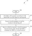
- Step 300Start.
- Step 302Determine a RA sequence according to a synchronization signal (SS) transmitted via a DL beam by a serving cell.
- SSsynchronization signal
- Step 304Transmit the RA sequence on the RA resource to the serving cell.
- Step 306Receive a RA response (RAR) in response to the RA sequence from the serving cell, wherein the RAR is scheduled by a DL control information (DCI) in a control resource.
- RARRA response
- DCIDL control information
- Step 308End.
- the communication devicedetermines a RA sequence according to a SS (e.g., a SS block) via a DL beam by a serving cell. Then, the communication device transmits the RA sequence on the RA resource to the serving cell, e.g., to perform a RA procedure. Accordingly, the communication device receives a RA response (RAR) in response to the RA sequence from the serving cell, wherein the RAR is scheduled by a DL control information (DCI) in a control resource. That is, a mechanism is provided for the communication device to perform the RA procedure.
- the communication devicecan communicate with the serving cell operated by the network regularly.
- Realization of the process 30is not limited to the above description. The following examples may be applied for realizing the process 30 .
- the communication deviceperforms at least one UL transmission with the serving cell, after receiving the RAR.
- the SScomprises at least one of a primary SS (PSS), a secondary SS (SSS), timing information, frequency information and a cell identity (ID) of the serving cell.
- the communication devicemay use the SS to obtain a boundary of an orthogonal frequency division multiplexing (OFDM) symbol and/or an error of a carrier frequency operated by the communication device.
- the communication devicemay use the cell ID to obtain information of a reference signal for performing a data demodulation and/or information of the beamforming (e.g., beam index).
- the SSmay be one of at least one SS transmitted by the serving cell.
- the at least one SSmay be transmitted via at least one DL beam by the serving cell.
- a SS of the at least one SSmay be associated with one of at least one DL transmission beam.
- the communication devicedetermines the RA sequence according to the SS and at least one of system information, a signal quality, information of the DL beam and a capability of the communication device.
- the above information and parameter(s)may be transmitted via the same resource or different resources, e.g., time resource and/or frequency resource.
- the RA resourceis determined (e.g., by the communication device) according to the SS. In one example, the RA resource is determined (e.g., by the communication device) according to the SS and at least one of system information, a signal quality, information of the DL beam and a capability of the communication device.
- the above information and parameter(s)may be transmitted via the same resource or different resources, e.g., time resource and/or frequency resource.
- a carrier spacing of the RA sequenceis determined according to (e.g., configured by) a higher layer signaling (e.g., radio resource control (RRC) signaling).
- RRCradio resource control
- the N repetitionsmay be determined according to a higher layer signaling (e.g., RRC signaling), may be determined according to a mapping table, or may be determined according to at least one signal quality of at least one DL beam.
- the communication devicedetermines a RA response (RAR) window and a RA-radio network temporary identifier (RA-RNTI), e.g., according to the RA sequence. Then, the communication device receives the RAR in the RAR window according to the RA-RNTI (e.g., by performing a blind detection). It should be noted that the communication device may determine a RA preamble index (RAPID) according to the RA sequence. Then, the communication device performs the at least one UL transmission with at least one timing advanced (TA) command according to at least one UL grant associated to the RAPID.
- RAPIDRA preamble index
- a search space for the communication device to receive/monitor the RARis determined according to a higher layer signaling (e.g., RRC signaling), the RA sequence and/or a RA resource.
- a first search space of the RARis used when the communication device is capable of performing advanced communication technique(s) (e.g., transmit beamforming and/or receive beamforming), and a second search space of the RAR is used when the communication device is not capable of performing the advanced communication technique(s).
- the DCIis received according to a reference signal determined according to at least one of the SS and a higher layer signaling (e.g., RRC signaling).
- the DCIis received according to a reference signal which is the same as another reference signal for receiving system information. That is, the same reference signal is used for receiving the DCI and the system information.
- the DCIis received according to a reference signal which is the same as another reference signal for receiving at least one of a UL grant DCI (e.g., for the transmission of Message 3 (Msg 3 )) and a DL assignment DCI (e.g., contention resolution or Message 4 (Msg 4 )) during the RA procedure.
- a UL grant DCIe.g., for the transmission of Message 3 (Msg 3 )
- a DL assignment DCIe.g., contention resolution or Message 4 (Msg 4 )
- the same reference signalis used for receiving the DCI for scheduling the RAR, the UL grant DCI and/or the DL assignment DCI during the RA procedure.
- the UL grant DCImay be a DCI for scheduling a UL transmission (e.g., physical UL shared channel (PUSCH)), and the DL assignment DCI may be a DCI for scheduling a DL reception (e.g., physical DL shared channel (PDSCH)).
- the DCIis received according to a reference signal which is the same as another reference signal for receiving another DCI for scheduling system information. That is, the same reference signal is used for receiving the DCI and the other DCI for the system information.
- control resourceis determined according to (e.g., configured by) at least one of a higher layer signaling, the RA sequence and the RA resource.
- the RA resourceis determined (e.g., by the communication device) according to the SS.
- the RA resourceis determined (e.g., the communication device) according to the SS and at least one of system information, a signal quality, information of the DL beam and a capability of the communication device.
- the RARincludes at least one UL grant for scheduling at least one UL transmission.
- the at least one UL transmissionis performed in contiguous time-domain resources or noncontiguous time-domain resources.
- two set of RA sequencesmay be configured by the network, wherein the first set of RA sequences may be selected by the communication device capable of operating advanced communication technique(s) and the second set of RA sequences may be selected by the communication device not capable of operating the advanced communication technique(s).
- a coverage area of the RAR scheduled for the communication device not capable of performing the advanced communication technique(s)should be considered, to ensure that the communication device can receive the RAR correctly.
- the communication devicedetermines a preamble index (RAPID) according to the RA sequence. Then, the communication device performs at least one UL transmission with the serving cell according to at least one UL grant associated to the RAIPID RAPID, after receiving the RAR.
- RAPIDpreamble index
- the communication devicereports a preferred DL transmission beam index or a suitable DL transmission beam index in the at least one UL transmission (e.g., Msg 3 ) to the serving cell.
- a beam(e.g., DL beam or UL beam) is formed by at least one antenna port of the serving cell.
- a DL beamis one of a plurality of DL beams of the serving cell for DL transmission.
- a UL beamis one of a plurality of UL beams of the serving cell for UL reception.
- a beam(e.g., DL beam or UL beam) is formed by at least one antenna port of the communication device.
- a DL beamis one of a plurality of DL beams of the communication device for DL reception.
- a UL beamis one of a plurality of UL beams of the communication device for UL transmission.
- the DL beamis for receiving at least one of the SS and/or system information. That is, the communication device determines that the DL beam for receiving the RAR is the same with the DL beam for receiving the SS and/or the system information. In one example, the DL beam is for receiving at least one of a UL grant DCI (e.g., Msg 3 ) and/or a DL assignment DCI (e.g., contention resolution or Msg 4 ) during the RA procedure. That is, the communication device determines that the DL beam for receiving the RAR is the same with the DL beam for receiving the UL grant DCI and/or DL assignment DCI.
- a UL grant DCIe.g., Msg 3
- a DL assignment DCIe.g., contention resolution or Msg 4
- the UL grant DCImay be a DCI for scheduling a UL transmission (e.g., PUSCH), and the DL assignment DCI may be a DCI for scheduling a DL reception (e.g., PDSCH).
- the DL beamis for performing a measurement. That is, the communication device determines that the DL beam for receiving the RAR is the same with the DL beam for performing the measurement.
- a same UL beamis for transmitting the RA sequence and for performing a UL transmission (e.g., Msg 3 ). That is, the communication device determines that the UL beam for transmitting the RA sequence is the same with the UL beam for performing the UL transmission (e.g., Msg 3 ).
- reception (or transmission) of different signals with the same beammay represent that these signals are received (or transmitted) via antenna ports with the same spatial parameters.
- At least one TA command and/or at least one transmission power control (TPC) command for the at least one UL transmissionmay be different.
- the at least one UL transmissionmay be associated with different hybrid automatic repeat request (HARQ) process IDs.
- At least one RNTI valuee.g., temporary cell-RNTI (TC-RNTI)
- TC-RNTItemporary cell-RNTI
- At least one transport block size scheduled for the at least one UL transmissionmay be the same.
- At least one UL physical resource reserved for the at least one UL transmissionmay be the same for the RAR.
- At least one UL physical resource reserved for the at least one UL transmissionmay be contiguous or not contiguous in a time domain.
- the same or different TA command(s), TPC command(s), HARQ process number and TC-RNTImay be applied to the at least one UL transmission.
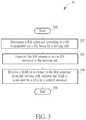
- FIG. 4is a schematic diagram of transmissions of RA sequences according to an example of the present invention.
- a BScommunicates with two communication devices CD 1 -CD 2 via DL beams DB 1 -DB 3 of a serving cell according to a beamforming.
- the BSmay sweep the DL beams DB 1 -DB 3 sequentially in time intervals T 1 -T 3 .
- the BSmay only receive signals via the DL beams DB 1 -DB 3 in the time intervals T 1 -T 3 , respectively.
- the communication devices CD 1 -CD 2are with coverage areas of the DL beams DB 1 and DB 3 , respectively.
- the communication device CD 1transmits a cyclic prefix (CP) in a time interval T 0 and a first RA sequence with 3 repetitions in the time intervals T 1 -T 3 to the BS.
- the communication device CD 2transmits a CP in a time interval T 0 and a second RA sequence with 3 repetitions in the time intervals T 1 -T 3 to the BS, wherein the first RA sequence and the second RA sequence may be the same or different.
- the BScan only receive the first repetition of the first RA sequence in the time interval T 1 , and can only receive the third repetition of the second RA sequence in the time interval T 3 . That is, the BS simply cannot detect/receive the other repetitions of the first RA sequence in the time intervals T 2 -T 3 , and cannot detect/receive the other repetitions of the second RA sequence in the time intervals T 1 -T 2 .
- the RA sequences from different communication devicesare separated, i.e., do not interfere with each other.
- a RA sequence with and without a CPmay be multiplied with a different orthogonal cover code (OCC), to be applied to the above examples.
- OOCCorthogonal cover code
- a RA sequencemay be Zadoff-Chu (ZC) sequence or a M-sequence (i.e., maximum length sequence), but is not limited herein.
- ZCZadoff-Chu
- M-sequencei.e., maximum length sequence
- Examples of the hardwaremay include analog circuit(s), digital circuit (s) and/or mixed circuit (s).
- the hardwaremay include ASIC(s), field programmable gate array(s) (FPGA(s)), programmable logic device(s), coupled hardware components or combination thereof.
- the hardwaremay include general-purpose processor(s), microprocessor(s), controller(s), digital signal processor(s) (DSP(s)) or combination thereof.
- Examples of the softwaremay include set(s) of codes, set(s) of instructions and/or set(s) of functions retained (e.g., stored) in a storage unit, e.g., a computer-readable medium.
- the computer-readable mediummay include SIM, ROM, flash memory, RAM, CD-ROM/DVD-ROM/BD-ROM, magnetic tape, hard disk, optical data storage device, non-volatile storage unit, or combination thereof.
- the computer-readable medium(e.g., storage unit) may be coupled to at least one processor internally (e.g., integrated) or externally (e.g., separated).
- the at least one processorwhich may include one or more modules may (e.g., be configured to) execute the software in the computer-readable medium.
- the set(s) of codes, the set(s) of instructions and/or the set(s) of functionsmay cause the at least one processor, the module(s), the hardware and/or the electronic system to perform the related steps.
- Examples of the electronic systemmay include a system on chip (SoC), system in package (SiP), a computer on module (CoM), a computer program product, an apparatus, a mobile phone, a laptop, a tablet computer, an electronic book or a portable computer system, and the communication device 20 .
- SoCsystem on chip
- SiPsystem in package
- CoMcomputer on module
- a computer program productan apparatus, a mobile phone, a laptop, a tablet computer, an electronic book or a portable computer system, and the communication device 20 .
- the present inventionprovides a device and method for handling a RA procedure. Solutions for transmitting and receiving RA sequences are proposed.
- a communication devicecan perform a RA procedure with a network, when a beamforming is realized by the network. As a result, the communication device can communicate with a serving cell operated by the network regularly.
Landscapes
- Engineering & Computer Science (AREA)
- Computer Networks & Wireless Communication (AREA)
- Signal Processing (AREA)
- Mobile Radio Communication Systems (AREA)
Abstract
Description
Claims (24)
Priority Applications (4)
| Application Number | Priority Date | Filing Date | Title |
|---|---|---|---|
| US15/867,728US10841954B2 (en) | 2017-01-13 | 2018-01-11 | Device of handling a random access procedure |
| CN201810035608.6ACN108401300B (en) | 2017-01-13 | 2018-01-15 | Method and apparatus for processing random access procedures |
| TW107101380ATWI723245B (en) | 2017-01-13 | 2018-01-15 | Device and method of handling a random access procedure |
| EP18151550.3AEP3349533B1 (en) | 2017-01-13 | 2018-01-15 | Device for handling a random access procedure |
Applications Claiming Priority (2)
| Application Number | Priority Date | Filing Date | Title |
|---|---|---|---|
| US201762445759P | 2017-01-13 | 2017-01-13 | |
| US15/867,728US10841954B2 (en) | 2017-01-13 | 2018-01-11 | Device of handling a random access procedure |
Publications (2)
| Publication Number | Publication Date |
|---|---|
| US20180206273A1 US20180206273A1 (en) | 2018-07-19 |
| US10841954B2true US10841954B2 (en) | 2020-11-17 |
Family
ID=61094194
Family Applications (1)
| Application Number | Title | Priority Date | Filing Date |
|---|---|---|---|
| US15/867,728ActiveUS10841954B2 (en) | 2017-01-13 | 2018-01-11 | Device of handling a random access procedure |
Country Status (4)
| Country | Link |
|---|---|
| US (1) | US10841954B2 (en) |
| EP (1) | EP3349533B1 (en) |
| CN (1) | CN108401300B (en) |
| TW (1) | TWI723245B (en) |
Families Citing this family (1)
| Publication number | Priority date | Publication date | Assignee | Title |
|---|---|---|---|---|
| CN110972322B (en)* | 2018-09-28 | 2022-10-28 | 华为技术有限公司 | Random access method and communication device |
Citations (20)
| Publication number | Priority date | Publication date | Assignee | Title |
|---|---|---|---|---|
| US20130039195A1 (en)* | 2011-08-10 | 2013-02-14 | Research In Motion Limited | Method and system for random access interference mitigation in heterogeneous cellular networks |
| EP2563073A1 (en) | 2010-12-31 | 2013-02-27 | Huawei Technologies Co., Ltd. | Serving node selective access method, device and system |
| US20130301619A1 (en)* | 2012-05-11 | 2013-11-14 | Samsung Electronics Co., Ltd | Methods and apparatus for uplink timing alignment in system with large number of antennas |
| WO2014139174A1 (en) | 2013-03-15 | 2014-09-18 | Qualcomm Incorporated | Improved random access procedure with beamforming in lte |
| US20140376466A1 (en) | 2013-06-24 | 2014-12-25 | Samsung Electronics Co., Ltd. | Apparatus and method for adaptively determining tx beam subset for random access in wireless communication system |
| EP2986075A1 (en) | 2013-05-10 | 2016-02-17 | ZTE Corporation | Random access method and system |
| WO2016061382A1 (en) | 2014-10-16 | 2016-04-21 | Qualcomm Incorporated | Channel state information procedure for enhanced component carriers |
| WO2016086144A1 (en) | 2014-11-26 | 2016-06-02 | Interdigital Patent Holdings, Inc. | Initial access in high frequency wireless systems |
| WO2016117981A1 (en) | 2015-01-23 | 2016-07-28 | 삼성전자 주식회사 | Method and device for supporting data communication in wireless communication system |
| US20160302230A1 (en)* | 2015-04-10 | 2016-10-13 | Samsung Electronics Co., Ltd | Methods and apparatus for rrm measurement on unlicensed spectrum |
| US20180098235A1 (en) | 2016-09-30 | 2018-04-05 | Motorola Mobility Llc | Method and apparatus for reporting channel state information |
| US20180103504A1 (en) | 2015-06-11 | 2018-04-12 | Huawei Technologies Co., Ltd. | Drx implementation method, drx configuration method, and related device |
| US20180199322A1 (en) | 2015-07-17 | 2018-07-12 | Ntt Docomo, Inc. | User terminal, radio base station, and radio communication method |
| US20180241458A1 (en)* | 2015-07-31 | 2018-08-23 | Intel IP Corporation | Network discovery and beam acquisition in 5g rat beam cell operation |
| US20180309533A1 (en)* | 2015-11-02 | 2018-10-25 | Sharp Kabushiki Kaisha | Base station apparatus, terminal apparatus, and communication method |
| US20190052331A1 (en)* | 2016-02-25 | 2019-02-14 | Intel IP Corporation | Device and method for synchronous beam switching |
| US20190159255A1 (en)* | 2016-06-28 | 2019-05-23 | Huawei Technologies Co., Ltd. | Communication Method on Unlicensed Frequency Band, Terminal Device, and Network Device |
| US20190274168A1 (en)* | 2015-12-18 | 2019-09-05 | Lg Electronics Inc. | Method and wireless device for transmitting random-access preamble by means of single-tone method |
| US20200059967A1 (en)* | 2016-11-06 | 2020-02-20 | Lg Electronics Inc. | Method and user equipment for transmitting random access signals, and method and base station for receiving random access signals |
| US20200128585A1 (en)* | 2017-01-06 | 2020-04-23 | Panasonic Intellectual Property Corporation Of America | Transmission of control information |
Family Cites Families (2)
| Publication number | Priority date | Publication date | Assignee | Title |
|---|---|---|---|---|
| KR101995798B1 (en)* | 2012-07-03 | 2019-07-03 | 삼성전자주식회사 | Device and method for random access in a wireless communication system using beamformig |
| EP3048851B1 (en)* | 2015-01-26 | 2020-03-11 | ASUSTek Computer Inc. | Method and apparatus for beam detection in a wireless communication system |
- 2018
- 2018-01-11USUS15/867,728patent/US10841954B2/enactiveActive
- 2018-01-15CNCN201810035608.6Apatent/CN108401300B/enactiveActive
- 2018-01-15TWTW107101380Apatent/TWI723245B/enactive
- 2018-01-15EPEP18151550.3Apatent/EP3349533B1/enactiveActive
Patent Citations (21)
| Publication number | Priority date | Publication date | Assignee | Title |
|---|---|---|---|---|
| EP2563073A1 (en) | 2010-12-31 | 2013-02-27 | Huawei Technologies Co., Ltd. | Serving node selective access method, device and system |
| US20130039195A1 (en)* | 2011-08-10 | 2013-02-14 | Research In Motion Limited | Method and system for random access interference mitigation in heterogeneous cellular networks |
| US20130301619A1 (en)* | 2012-05-11 | 2013-11-14 | Samsung Electronics Co., Ltd | Methods and apparatus for uplink timing alignment in system with large number of antennas |
| WO2014139174A1 (en) | 2013-03-15 | 2014-09-18 | Qualcomm Incorporated | Improved random access procedure with beamforming in lte |
| EP2986075A1 (en) | 2013-05-10 | 2016-02-17 | ZTE Corporation | Random access method and system |
| US20140376466A1 (en) | 2013-06-24 | 2014-12-25 | Samsung Electronics Co., Ltd. | Apparatus and method for adaptively determining tx beam subset for random access in wireless communication system |
| WO2016061382A1 (en) | 2014-10-16 | 2016-04-21 | Qualcomm Incorporated | Channel state information procedure for enhanced component carriers |
| WO2016086144A1 (en) | 2014-11-26 | 2016-06-02 | Interdigital Patent Holdings, Inc. | Initial access in high frequency wireless systems |
| US20170141833A1 (en) | 2015-01-23 | 2017-05-18 | Samsung Electronics Co., Ltd. | Method and device for supporting data communication in wireless communication system |
| WO2016117981A1 (en) | 2015-01-23 | 2016-07-28 | 삼성전자 주식회사 | Method and device for supporting data communication in wireless communication system |
| US20160302230A1 (en)* | 2015-04-10 | 2016-10-13 | Samsung Electronics Co., Ltd | Methods and apparatus for rrm measurement on unlicensed spectrum |
| US20180103504A1 (en) | 2015-06-11 | 2018-04-12 | Huawei Technologies Co., Ltd. | Drx implementation method, drx configuration method, and related device |
| US20180199322A1 (en) | 2015-07-17 | 2018-07-12 | Ntt Docomo, Inc. | User terminal, radio base station, and radio communication method |
| US20180241458A1 (en)* | 2015-07-31 | 2018-08-23 | Intel IP Corporation | Network discovery and beam acquisition in 5g rat beam cell operation |
| US20180309533A1 (en)* | 2015-11-02 | 2018-10-25 | Sharp Kabushiki Kaisha | Base station apparatus, terminal apparatus, and communication method |
| US20190274168A1 (en)* | 2015-12-18 | 2019-09-05 | Lg Electronics Inc. | Method and wireless device for transmitting random-access preamble by means of single-tone method |
| US20190052331A1 (en)* | 2016-02-25 | 2019-02-14 | Intel IP Corporation | Device and method for synchronous beam switching |
| US20190159255A1 (en)* | 2016-06-28 | 2019-05-23 | Huawei Technologies Co., Ltd. | Communication Method on Unlicensed Frequency Band, Terminal Device, and Network Device |
| US20180098235A1 (en) | 2016-09-30 | 2018-04-05 | Motorola Mobility Llc | Method and apparatus for reporting channel state information |
| US20200059967A1 (en)* | 2016-11-06 | 2020-02-20 | Lg Electronics Inc. | Method and user equipment for transmitting random access signals, and method and base station for receiving random access signals |
| US20200128585A1 (en)* | 2017-01-06 | 2020-04-23 | Panasonic Intellectual Property Corporation Of America | Transmission of control information |
Non-Patent Citations (9)
| Title |
|---|
| European search opinion, dated May 17, 2018, Global Dossier, [retrieved on Mar. 13, 2019] Retrieved from Internet <URL: https://opd-ui.uspto.gov/#/docurnent-page/EP:18151550:A> (Year: 2018).* |
| HUAWEI HISILICON: "Discussion on CSI feedback for short TTI", 3GPP DRAFT; R1-1611166, 3RD GENERATION PARTNERSHIP PROJECT (3GPP), MOBILE COMPETENCE CENTRE ; 650, ROUTE DES LUCIOLES ; F-06921 SOPHIA-ANTIPOLIS CEDEX ; FRANCE, vol. RAN WG1, no. Reno, USA; 20161114 - 20161118, R1-1611166, 13 November 2016 (2016-11-13), Mobile Competence Centre ; 650, route des Lucioles ; F-06921 Sophia-Antipolis Cedex ; France, XP051175147 |
| Huawei, HiSilicon, Discussion on CSI feedback for short TTI, 3GPP TSG RAN WG1 Meeting #87, R1-1611166, Reno, USA, Nov. 14-18, 2016, XP051175147. |
| Motorola Mobility, Control signalling for shortened TTI, 3GPP TSG RAN WG1#87, R1-1612741, Nov. 14-19, 2016, Reno, USA, XP051176684. |
| Motorola Mobility, CSI aspects of shortened TTI, 3GPP TSG RAN WG1#87, R1-1612743, Nov. 14-19, 2016, Reno, USA, XP051176685. |
| MOTOROLA MOBILITY: "Control signalling for shortened TTI", 3GPP DRAFT; R1-1612741_SPDCCH_V0, 3RD GENERATION PARTNERSHIP PROJECT (3GPP), MOBILE COMPETENCE CENTRE ; 650, ROUTE DES LUCIOLES ; F-06921 SOPHIA-ANTIPOLIS CEDEX ; FRANCE, vol. RAN WG1, no. Reno, USA; 20161114 - 20161119, R1-1612741_sPDCCH_v0, 13 November 2016 (2016-11-13), Mobile Competence Centre ; 650, route des Lucioles ; F-06921 Sophia-Antipolis Cedex ; France, XP051176684 |
| MOTOROLA MOBILITY: "CSI aspects of shortened TTI", 3GPP DRAFT; R1-1612743_SCSI_V0, 3RD GENERATION PARTNERSHIP PROJECT (3GPP), MOBILE COMPETENCE CENTRE ; 650, ROUTE DES LUCIOLES ; F-06921 SOPHIA-ANTIPOLIS CEDEX ; FRANCE, vol. RAN WG1, no. Reno, USA; 20161114 - 20161119, R1-1612743_sCSI_v0, 13 November 2016 (2016-11-13), Mobile Competence Centre ; 650, route des Lucioles ; F-06921 Sophia-Antipolis Cedex ; France, XP051176685 |
| NTT DOCOMO INC.: "Views on CSI feedback for shortened TTI with reduced processing time", 3GPP DRAFT; R1-1612699, 3RD GENERATION PARTNERSHIP PROJECT (3GPP), MOBILE COMPETENCE CENTRE ; 650, ROUTE DES LUCIOLES ; F-06921 SOPHIA-ANTIPOLIS CEDEX ; FRANCE, vol. RAN WG1, no. Reno, USA; 20161114 - 20161118, R1-1612699, 13 November 2016 (2016-11-13), Mobile Competence Centre ; 650, route des Lucioles ; F-06921 Sophia-Antipolis Cedex ; France, XP051176642 |
| NTT DOCOMO, Inc., Views on CSI feedback for shortened TTI with reduced processing time, 3GPP TSG RAN WG1 Meeting #87, R1-1612699, Reno, USA, Nov. 14-18, 2016, pp. 1-7, XP051176642. |
Also Published As
| Publication number | Publication date |
|---|---|
| TW201826868A (en) | 2018-07-16 |
| US20180206273A1 (en) | 2018-07-19 |
| CN108401300A (en) | 2018-08-14 |
| CN108401300B (en) | 2022-04-26 |
| TWI723245B (en) | 2021-04-01 |
| EP3349533A1 (en) | 2018-07-18 |
| EP3349533B1 (en) | 2021-03-10 |
Similar Documents
| Publication | Publication Date | Title |
|---|---|---|
| CN113574924B (en) | Waveform configuration and indication for uplink transmission | |
| US10892811B2 (en) | Beam recovery procedure using a second component carrier | |
| KR102696046B1 (en) | Enhanced random access channel (rach) procedure | |
| US9386619B2 (en) | Method of handling a cell addition for dual connectivity and related communication device | |
| EP3016427B1 (en) | Device of handling service in an unlicensed cell in the context of license assisted lte | |
| US20170318596A1 (en) | Device and Method of Handling Device-to-Device Communication | |
| US20160135056A1 (en) | Device of Handling Measurement Signal on Unlicensed Carrier | |
| EP3432638A1 (en) | Device for handling a handover | |
| US11240842B2 (en) | Device and method of handling transmission/reception for serving cell | |
| US9774427B2 (en) | Method of handling uplink/downlink configurations for time-division duplexing system and related communication device | |
| US9882699B2 (en) | Device and method of handling device-to-cellular communication | |
| EP3013109B1 (en) | Device of handling resource availability of unlicensed band | |
| US10356823B2 (en) | Random access message transmission using multiple symbols | |
| US11894952B2 (en) | Device and method of handling an uplink transmission with sounding reference signals | |
| EP3440886A1 (en) | Scheduling request transmission to request resources for a buffer status report | |
| US12323971B2 (en) | Device of handling PUSCH transmissions | |
| US10841954B2 (en) | Device of handling a random access procedure | |
| US10477436B2 (en) | Device and method of handling transmission in unlicensed band | |
| US9860805B2 (en) | Device of handling energy detection in unlicensed band | |
| EP3046392B1 (en) | Method and apparatus for handling a cell addition for dual connectivity |
Legal Events
| Date | Code | Title | Description |
|---|---|---|---|
| AS | Assignment | Owner name:ACER INCORPORATED, TAIWAN Free format text:ASSIGNMENT OF ASSIGNORS INTEREST;ASSIGNOR:LEE, CHIEN-MIN;REEL/FRAME:044590/0949 Effective date:20170922 | |
| FEPP | Fee payment procedure | Free format text:ENTITY STATUS SET TO UNDISCOUNTED (ORIGINAL EVENT CODE: BIG.); ENTITY STATUS OF PATENT OWNER: LARGE ENTITY | |
| STPP | Information on status: patent application and granting procedure in general | Free format text:NON FINAL ACTION MAILED | |
| STPP | Information on status: patent application and granting procedure in general | Free format text:FINAL REJECTION MAILED | |
| STPP | Information on status: patent application and granting procedure in general | Free format text:DOCKETED NEW CASE - READY FOR EXAMINATION | |
| STPP | Information on status: patent application and granting procedure in general | Free format text:NOTICE OF ALLOWANCE MAILED -- APPLICATION RECEIVED IN OFFICE OF PUBLICATIONS | |
| STPP | Information on status: patent application and granting procedure in general | Free format text:PUBLICATIONS -- ISSUE FEE PAYMENT RECEIVED | |
| STPP | Information on status: patent application and granting procedure in general | Free format text:PUBLICATIONS -- ISSUE FEE PAYMENT VERIFIED | |
| STCF | Information on status: patent grant | Free format text:PATENTED CASE | |
| MAFP | Maintenance fee payment | Free format text:PAYMENT OF MAINTENANCE FEE, 4TH YEAR, LARGE ENTITY (ORIGINAL EVENT CODE: M1551); ENTITY STATUS OF PATENT OWNER: LARGE ENTITY Year of fee payment:4 |