US10838902B2 - Apparatus, system, and method for performing hardware acceleration via expansion cards - Google Patents
Apparatus, system, and method for performing hardware acceleration via expansion cardsDownload PDFInfo
- Publication number
- US10838902B2 US10838902B2US15/631,861US201715631861AUS10838902B2US 10838902 B2US10838902 B2US 10838902B2US 201715631861 AUS201715631861 AUS 201715631861AUS 10838902 B2US10838902 B2US 10838902B2
- Authority
- US
- United States
- Prior art keywords
- computing
- expansion
- expansion card
- pinout
- task
- Prior art date
- Legal status (The legal status is an assumption and is not a legal conclusion. Google has not performed a legal analysis and makes no representation as to the accuracy of the status listed.)
- Active, expires
Links
Images


Classifications
- H—ELECTRICITY
- H05—ELECTRIC TECHNIQUES NOT OTHERWISE PROVIDED FOR
- H05K—PRINTED CIRCUITS; CASINGS OR CONSTRUCTIONAL DETAILS OF ELECTRIC APPARATUS; MANUFACTURE OF ASSEMBLAGES OF ELECTRICAL COMPONENTS
- H05K7/00—Constructional details common to different types of electric apparatus
- H05K7/14—Mounting supporting structure in casing or on frame or rack
- H05K7/1485—Servers; Data center rooms, e.g. 19-inch computer racks
- G—PHYSICS
- G06—COMPUTING OR CALCULATING; COUNTING
- G06F—ELECTRIC DIGITAL DATA PROCESSING
- G06F13/00—Interconnection of, or transfer of information or other signals between, memories, input/output devices or central processing units
- G06F13/38—Information transfer, e.g. on bus
- G06F13/40—Bus structure
- G06F13/4004—Coupling between buses
- G06F13/4022—Coupling between buses using switching circuits, e.g. switching matrix, connection or expansion network
- G—PHYSICS
- G06—COMPUTING OR CALCULATING; COUNTING
- G06F—ELECTRIC DIGITAL DATA PROCESSING
- G06F1/00—Details not covered by groups G06F3/00 - G06F13/00 and G06F21/00
- G06F1/16—Constructional details or arrangements
- G06F1/18—Packaging or power distribution
- G06F1/183—Internal mounting support structures, e.g. for printed circuit boards, internal connecting means
- G06F1/185—Mounting of expansion boards
- G—PHYSICS
- G06—COMPUTING OR CALCULATING; COUNTING
- G06F—ELECTRIC DIGITAL DATA PROCESSING
- G06F1/00—Details not covered by groups G06F3/00 - G06F13/00 and G06F21/00
- G06F1/16—Constructional details or arrangements
- G06F1/18—Packaging or power distribution
- G06F1/183—Internal mounting support structures, e.g. for printed circuit boards, internal connecting means
- G06F1/186—Securing of expansion boards in correspondence to slots provided at the computer enclosure
- G—PHYSICS
- G06—COMPUTING OR CALCULATING; COUNTING
- G06F—ELECTRIC DIGITAL DATA PROCESSING
- G06F1/00—Details not covered by groups G06F3/00 - G06F13/00 and G06F21/00
- G06F1/26—Power supply means, e.g. regulation thereof
- G06F1/32—Means for saving power
- G06F1/3203—Power management, i.e. event-based initiation of a power-saving mode
- G06F1/3234—Power saving characterised by the action undertaken
- G06F1/3296—Power saving characterised by the action undertaken by lowering the supply or operating voltage
- G—PHYSICS
- G06—COMPUTING OR CALCULATING; COUNTING
- G06F—ELECTRIC DIGITAL DATA PROCESSING
- G06F13/00—Interconnection of, or transfer of information or other signals between, memories, input/output devices or central processing units
- G06F13/38—Information transfer, e.g. on bus
- G06F13/382—Information transfer, e.g. on bus using universal interface adapter
- G06F13/385—Information transfer, e.g. on bus using universal interface adapter for adaptation of a particular data processing system to different peripheral devices
- G—PHYSICS
- G06—COMPUTING OR CALCULATING; COUNTING
- G06F—ELECTRIC DIGITAL DATA PROCESSING
- G06F13/00—Interconnection of, or transfer of information or other signals between, memories, input/output devices or central processing units
- G06F13/38—Information transfer, e.g. on bus
- G06F13/40—Bus structure
- G06F13/4063—Device-to-bus coupling
- G06F13/4068—Electrical coupling
- G—PHYSICS
- G06—COMPUTING OR CALCULATING; COUNTING
- G06F—ELECTRIC DIGITAL DATA PROCESSING
- G06F13/00—Interconnection of, or transfer of information or other signals between, memories, input/output devices or central processing units
- G06F13/38—Information transfer, e.g. on bus
- G06F13/42—Bus transfer protocol, e.g. handshake; Synchronisation
- G06F13/4282—Bus transfer protocol, e.g. handshake; Synchronisation on a serial bus, e.g. I2C bus, SPI bus
- G—PHYSICS
- G06—COMPUTING OR CALCULATING; COUNTING
- G06F—ELECTRIC DIGITAL DATA PROCESSING
- G06F15/00—Digital computers in general; Data processing equipment in general
- G—PHYSICS
- G06—COMPUTING OR CALCULATING; COUNTING
- G06F—ELECTRIC DIGITAL DATA PROCESSING
- G06F15/00—Digital computers in general; Data processing equipment in general
- G06F15/76—Architectures of general purpose stored program computers
- G06F15/78—Architectures of general purpose stored program computers comprising a single central processing unit
- G06F15/7803—System on board, i.e. computer system on one or more PCB, e.g. motherboards, daughterboards or blades
- G—PHYSICS
- G06—COMPUTING OR CALCULATING; COUNTING
- G06F—ELECTRIC DIGITAL DATA PROCESSING
- G06F9/00—Arrangements for program control, e.g. control units
- G06F9/06—Arrangements for program control, e.g. control units using stored programs, i.e. using an internal store of processing equipment to receive or retain programs
- G06F9/46—Multiprogramming arrangements
- G06F9/50—Allocation of resources, e.g. of the central processing unit [CPU]
- G06F9/5005—Allocation of resources, e.g. of the central processing unit [CPU] to service a request
- G06F9/5027—Allocation of resources, e.g. of the central processing unit [CPU] to service a request the resource being a machine, e.g. CPUs, Servers, Terminals
- G06F9/5044—Allocation of resources, e.g. of the central processing unit [CPU] to service a request the resource being a machine, e.g. CPUs, Servers, Terminals considering hardware capabilities
- G—PHYSICS
- G06—COMPUTING OR CALCULATING; COUNTING
- G06F—ELECTRIC DIGITAL DATA PROCESSING
- G06F2209/00—Indexing scheme relating to G06F9/00
- G06F2209/50—Indexing scheme relating to G06F9/50
- G06F2209/509—Offload
- G—PHYSICS
- G06—COMPUTING OR CALCULATING; COUNTING
- G06F—ELECTRIC DIGITAL DATA PROCESSING
- G06F2213/00—Indexing scheme relating to interconnection of, or transfer of information or other signals between, memories, input/output devices or central processing units
- G06F2213/0032—Serial ATA [SATA]
Definitions
- such an expansion cardmay include a printed circuit board and a hardware accelerator.
- the hardware acceleratormay be disposed on the printed circuit board and may include application-specific hardware circuitry designed to perform a computing task.
- the hardware acceleratormay offload at least a portion of the computing task from a central processing unit of a computing device by executing, via the application-specific hardware circuitry, at least a portion of the computing task.
- the expansion cardmay also include an edge connector, disposed on the printed circuit board, that is dimensioned to be inserted into an expansion socket of the computing device.
- the edge connectormay couple the hardware accelerator to the central processing unit via a computing bus connected to the expansion socket.
- the edge connectormay also include a pinout that is more compact than a pinout specification defined for the computing bus.
- the pinout of the edge connectormay conform to an M.2 pinout specification, a U.2 pinout specification, and/or an mSATA pinout specification.
- the hardware acceleratormay include a field-programmable gate array and/or an application-specific integrated circuit.
- the expansion cardmay further include a voltage regulator that stabilizes voltage received via the expansion socket and supplies he stabilized voltage to the hardware accelerator.
- the computing task that the application-specific hardware circuitry is designed to performmay include an artificial intelligence inference task that applies a model trained on known data to infer at least one label for new data.
- the computing task that the application-specific hardware circuitry is designed to performmay include a video transcoding task.
- a system incorporating the above-described apparatusmay include a central processing unit, a memory device, an expansion socket, and an expansion card.
- the expansion cardmay include a printed circuit board and a hardware accelerator that is disposed on the printed circuit board.
- the hardware acceleratormay include application-specific hardware circuitry designed to perform a computing task.
- the hardware acceleratoray offload at least a portion of the computing task from the central processing unit by executing, via the application-specific hardware circuitry, at least a portion of the computing task.
- the expansion cardmay also include an edge connector, disposed on the printed circuit board, that is dimensioned to be inserted into the expansion socket.
- the edge connectormay couple the hardware accelerator to the central processing unit via a computing bus connected to the expansion socket.
- the edge connectormay also include a pinout that is more compact than a pinout specification defined for the computing bus.
- the expansion socketmay be disposed on an intermediary expansion card that includes a pinout that conforms to the pinout specification defined for the computing bus.
- the systemmay include a chassis that is dimensioned to accept a plurality of modular computing devices.
- the expansion socketmay be disposed on a modular computing device inserted into the chassis.
- the systemmay include a chassis that is dimensioned to accept a plurality of modular storage devices.
- the expansion socketmay be disposed on a modular storage device inserted into the chassis.
- the systemmay represent a domain controller server and/or or an edge server.
- offloading at least a portion of the computing task from the central processing unit of the edge servermay enable the edge server to perform the computing task.
- the systemmay represent a backend data center of a corporate networking enterprise that provides at least one online service to corresponding users of client devices.
- the online servicemay, for example, represent a social networking service, a virtual reality service, and/or a cloud storage service.
- a corresponding methodmay include inserting an expansion card into an expansion socket of a computing device.
- the expansion cardmay include a printed circuit board and a hardware accelerator that is disposed on the printed circuit board.
- the hardware acceleratormay include application-specific hardware circuitry designed to perform a computing task.
- the expansion cardmay also include an edge connector, disposed on the printed circuit board, that is dimensioned to be inserted into the expansion socket of the computing device.
- the edge connectormay couple the hardware accelerator to a central processing unit of the computing device via a computing bus connected to the expansion socket.
- the edge connectormay also include a pinout that is more compact than a pinout specification defined for the computing bus.
- the methodmay include offloading at least a portion of the computing task from the central processing unit by executing, via the application-specific hardware circuitry, at least a portion of the computing task.
- the methodmay further include scaling the hardware acceleration capabilities of the computing device by inserting an additional expansion card into an additional expansion socket of the computing device.
- the additional expansion cardmay include at least one additional hardware accelerator that includes additional application-specific hardware circuitry designed to perform the computing task.
- the additional expansion cardmay also include an additional edge connector that includes an additional pinout that is more compact than the pinout specification defined for the computing bus.
- inserting the expansion card into the expansion socketmay include inserting the expansion card into a socket of an intermediary expansion card that is inserted into the expansion socket of the computing device.
- the intermediary expansion cardmay include a pinout that conforms to the pinout specification defined for the computing bus.
- FIG. 1is a block diagram of an example expansion card capable of performing hardware acceleration.
- FIG. 2is a more specific block diagram of an example expansion card capable of performing hardware acceleration.
- FIG. 3is a set of block diagrams of various example pinouts that may be used by the expansion cards described herein.
- FIG. 4is a perspective view of an example expansion card.
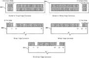
- FIG. 5Ais a perspective view of an initial stage of a process for inserting an example expansion card into a corresponding expansion socket.
- FIG. 5Bis a perspective view of an intermediate stage of the process for inserting the example expansion card into the corresponding expansion socket.
- FIG. 5Cis a perspective view of a concluding stage of the process for inserting the example expansion card into the corresponding expansion socket.
- FIG. 6is a block diagram of an example multi-node compute platform on which the expansion cards described herein may be deployed.
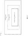
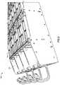
- FIG. 7is a perspective view of an example multi-node compute platform sled capable of housing the expansion cards described herein.
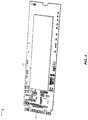
- FIG. 8is a perspective view of an example chassis capable of housing various multi-node compute platform sleds on which the expansion cards described herein may be deployed.
- FIG. 9is a block diagram of an example intermediary expansion card on which the expansion cards described herein may be deployed.
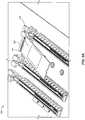
- FIG. 10Ais a perspective view of an example intermediary expansion card with a heatsink lifted to access a corresponding expansion card.
- FIG. 10Bis a plan view of the example intermediary expansion card of FIG. 10A in which the heatsink has been removed to access the corresponding expansion card.
- FIG. 11is a flow diagram of an example method for performing hardware acceleration via expansion cards.
- the present disclosuredescribes various apparatuses, systems, and methods for performing hardware acceleration via expansion cards.
- the devices disclosed hereinmay enable efficient, effective, and scalable hardware acceleration by coupling hardware accelerators to compact expansion cards (e.g., expansion cards such as M.2, U.2, and mSATA cards, whose pinouts are more compact than pinout specifications defined for the buses they use).
- compact expansion cardse.g., expansion cards such as M.2, U.2, and mSATA cards, whose pinouts are more compact than pinout specifications defined for the buses they use).
- While compact expansion cardshave traditionally been used for storage and wireless communications, repurposing compact cards for hardware acceleration may provide various advantages over traditional hardware acceleration solutions. For example, by offloading specific, complex computational tasks to hardware accelerators on expansion cards, the disclosed systems may reduce the computational demand on more expensive devices (such as domain controllers), potentially resulting in monetary and/or power savings.
- the disclosed systems and methodsmay also enable lightweight devices (such as edge servers) in various points-of-presence to perform computing tasks that they would otherwise lack the computing resources to handle.
- the disclosed hardware acceleratorsmay perform such tasks more effectively and/or efficiently than general-purpose computing devices.
- the disclosed expansion cards (and their hardware accelerators)may be quickly and easily deployed and granularly scaled across an entire computing ecosystem, thereby enabling technology companies to efficiently and effectively keep pace with the ever-increasing demand of computationally intensive tasks.
- FIGS. 1-4examples of an expansion card (and various pinout specifications that enable a compact footprint for the same) that is capable of performing hardware acceleration.
- FIGS. 5A-5C and FIGS. 10A-10Bwill provide an overview of exemplary techniques for inserting and/or removing such expansion cards into corresponding expansion sockets.
- the description corresponding to FIGS. 6-10will illustrate the scalability of these expansion cards, while the description corresponding to FIG. 11 will describe an exemplary workflow for adding hardware acceleration capabilities to a computing device using one or more of the example expansion cards illustrated in previous figures.
- FIG. 1is a block diagram of an example expansion card 100 capable of performing hardware acceleration according to the systems and methods disclosed herein.
- expansion card 100may include a printed circuit board 102 and one or more components disposed on printed circuit board 102 .
- the term “expansion card”generally refers to a card, such as a card substantially formed by a printed circuit board, that is configured for insertion into a corresponding computing device or expansion socket to thereby expand the functionality of the computing device.
- expansion card 100may include a hardware accelerator 104 disposed on printed circuit board 102 .
- the term “hardware accelerator,” as used herein,generally refers to a hardware component or device that performs one or more specialized computing tasks more efficiently, in hardware, than the computing task would be performed in software by a general purpose central processing unit (i.e., a computing chip that is structured to execute a range of different programs as software).
- “hardware acceleration”may refer to the execution of a computing task in application-specific hardware circuitry that occurs in the absence of a software module intermediary or other layer of abstraction, such that the performance of the application is more efficient than when executed otherwise.
- hardware accelerator 104may include application-specific hardware circuitry 106 designed to perform a specific computing task.
- hardware accelerator 104may be designed to offload a portion of the specific computing task from a central processing unit of a computing device, such as a data center server, by executing, via application-specific hardware circuitry 106 , at least a portion of the specific computing task.
- the phrase “offload a portion of the computing task from a central processing unit of a computing device,” as used herein,may generally refer to performing the computing task through the hardware accelerator rather than performing the computing ask through a general purpose central processing unit (i.e., a central processing unit of the computing device to which expansion card 100 is coupled, or another central processing unit that might otherwise perform the computing task in the absence of expansion card 100 ).
- a general purpose central processing uniti.e., a central processing unit of the computing device to which expansion card 100 is coupled, or another central processing unit that might otherwise perform the computing task in the absence of expansion card 100 .
- expansion card 100may also include an edge connector (such as edge connector 110 in FIG. 4 ), disposed on printed circuit board 102 , that is dimensioned to be inserted into an expansion socket of a computing device.
- edge connectormay couple hardware accelerator 104 to the central processing unit of the computing device via a computing bus connected to the expansion socket.
- edge connectorgenerally refers to one or more connections at an edge of an expansion card that couple the expansion card to a corresponding computing bus or computing device.
- this edge connectoray be formed of a portion of a printed circuit board, such as printed circuit board 102 .
- this edge connectormay include traces (i.e., pins) on the printed circuit board leading to the edge of the board, which may be designed or configured to be plugged into a matching socket.
- the edge connectormay include a e connector that matches a corresponding female connector or socket at a computing device (e.g., on the computing device motherboard).
- the edge connectormay be keyed to ensure a correct polarity.
- the connectorsmay also contain bumps or notches both for polarity and to ensure that the wrong type of device is not inserted into an expansion socket.
- the edge connectorin addition to having the correct keying, may have a width and thickness designed to fit into the expansion socket.
- the edge connectormay include a compact pinout that is more compact than a pinout specification defined for the computing bus to which the expansion card (and, in turn, its hardware accelerator) is coupled.
- pinoutgenerally refers to a cross-reference between the contacts, or pins, of an electrical connector or electronic component, such as expansion card 100 , as well as the functions of these contacts or pins.
- a compact pinoutmay be more compact than at least one other specified pinout by having a narrower, thinner, or otherwise smaller width dimension than the other pinout, having a narrower, thinner, or otherwise smaller thickness dimension than the other pinout, having closer pin pitch than the other pinout, having narrower, thinner, or smaller pins than the other pinout, and/or by being smaller than the other pinout n any other manner or dimension.
- M.2 cardsmay have a set of 75 pin spaces, and this set of pin space may be 12 mm, 16 mm, 22 mm, or 30 mm wide.
- the pinsmay also have a length of 2.00 mm and a pitch of 0.5 mm.
- the specification for a native PCI EXPRESS x1 pinoutmay define a pitch of at least 1.0 mm, a width of at least 35 mm, and a length of at least 2.3 mm.
- an M.2 pinoutwhich may connect to a PCI EXPRESS bus, may be said to be more compact than a pinout defined by a specification for the PCI EXPRESS bus since at least one dimension of the M.2 pinout is smaller than the pinout defined by the specification for the PCI EXPRESS bus.
- the edge connector of expansion card 100may have a pinout that conforms to one or more mixed-pin pinout specifications.
- the term “mixed-pin”generally refers to an expansion card having a pinout that differs from a pinout of the specification of a computing bus to which the expansion card couples.
- the expansion cardmay successfully couple with the computing bus, despite the conflict between the two pinouts, because the corresponding expansion socket may include one or more items of intermediary circuitry that effectively couples connections and/or translates data from the expansion card pinout into a format accepted by the computing bus, and vice versa.
- Illustrative examples of mixed-pin specifications to which the pinout of the edge connector may conforminclude an M.2 pinout specification, a U.2 pinout specification, and/or an mSATA pinout specification.
- hardware accelerator 104 of expansion card 100may be customized or special-purpose designed to perform, in hardware, one or more specific computing tasks.
- Illustrative examples of the types of specific computing tasks or applications that hardware accelerator 104 of expansion card 100 may execute or performinclude, without limitation, artificial intelligence and/or machine learning training (e.g., model construction, inference, flasher labeling, etc.), video transcoding (e.g., converting video data from one encoded format to an intermediate uncompressed format and then converting the intermediate uncompressed format to another encoded format or target format), video processing (e.g., combining two or more video streams into a single video stream or a fewer number of video streams), data encryption/decryption, data compression/decompression, etc.
- artificial intelligence and/or machine learning traininge.g., model construction, inference, flasher labeling, etc.
- video transcodinge.g., converting video data from one encoded format to an intermediate uncompressed format and then converting the intermediate uncompressed format to another encoded format
- hardware accelerator 104 of expansion card 100may be especially suited to, or beneficial for, the performance of specific types of mathematical operations, which may include multiply-accumulate operations, linear algebra operations, machine learning or vector tuning operations, and/or cryptographic prime number identification and/or verification operations.
- hardware accelerator 104 of expansion card 100may be customized or special-purpose designed to perform, in hardware, any type or form of computation-intensive computing task to thereby alleviate the burden on one or snore general-purpose central processing units (i.e., by performing the computing task on a separate chip than the central processing unit and/or by performing the computing task more efficiently in hardware than in software).
- the computing task that application-specific hardware circuitry 106 of hardware accelerator 104 is designed to performmay include an artificial intelligence inference task that applies a model trained on known data to infer at least one label for new data.
- an artificial intelligence inference task that applies a model trained on known datagenerally refers to the process of applying a trained model rather than the process of generating, training, and/or tuning the model.
- hardware accelerator 104 of expansion card 100may effectively label one or more items of newly encountered, or newly analyzed, data with a label or attribute.
- the modelmay be generated, trained, and/or tuned based on previously encountered data that was partially, or entirely, labeled, thereby enabling a machine learning algorithm to predict one or more labels for future data (e.g., by detecting patterns in the labels of the previously encountered data).
- the artificial intelligence inference taskmay include a user attribute inference task in the context of an online social networking system.
- the user attributemay include an interest, a recommendation (e.g., an advertisement recommendation and/or a friend recommendation), and/or a push notification (e.g., a social network post selected for the user's newsfeed).
- the artificial intelligence inference taskmay identify one or more of these labels or attributes for a user based on one or more items of data and/or metadata for the user, including the user's post history, post content, social media “likes” or response icon selections, friends list, message history, message content, and/or selected or clicked items, including newsfeed items and/or advertisements.
- the artificial intelligence inference taskmay infer, or predict, that a user with one set of data or metadata will tend to share a label with another user having a similar or identical set of data or metadata (e.g., the strength of the prediction may be proportional to the similarity between the two users' items of data/metadata).
- Hardware accelerator 104may take a variety of forms. Illustrative examples of hardware accelerators include, without limitation, graphics processing units, cryptographic accelerators, video processing units, artificial intelligence accelerators, coprocessors, digital signal processors, and/or public key encryption accelerators. In some examples, hardware accelerator 104 may be implemented via an application specific integrated circuit (ASIC) and/or a field-programmable gate array (FPGA).
- ASICapplication specific integrated circuit
- FPGAfield-programmable gate array
- FIG. 2shows a block diagram of a more specific example of expansion card 100 .
- expansion card 100may include a hardware accelerator in the form of an ASIC 201 .
- expansion card 100may include a variety of additional components, such as one or more voltage regulators 202 that may stabilize voltage received via a corresponding expansion socket of a computing device and supply the same to hardware accelerator 104 .
- expansion card 100may also include one or more instances of dynamic random-access memory (DRAM) 204 , each of which may be coupled to hardware accelerator 104 .
- Expansion card 100may also include one or more passive components 206 , including resistors, capacitors, inductors, and/or transistors.
- DRAMdynamic random-access memory
- expansion card 100may also include one or more active components. Each of the passive components and/or active components may be specifically designed and/or placed on expansion card 100 in a configuration that executes or performs (and/or enables ASIC 201 to perform), in hardware, the specific application in question, such as the video transcoding and/or artificial intelligence inference tasks described above.
- expansion card 100may also include a computing bus interface 208 , such as a PCI EXPRESS interface, which may translate data formatted by ASIC 201 for transmission across the edge connector and/or the computing bus to which expansion card 100 may be coupled.
- the edge connector of expansion card 100may have a pinout that conforms to one or more mixed-pin pinout specifications, such as the M.2 specification.
- FIG. 3illustrates various examples of edge connector pinouts, conforming to the M.2 specification, that expansion card 100 may utilize.
- elements 302 and 304illustrate the pinouts for expansion sockets that conform to the “B key” and “M key” edge connector configurations of the M.2 specification.
- the edge connector 110 of expansion card 100 from FIG. 1may include pinouts for “B key” and “M key” edge connectors, as illustrated by elements 306 and 308 , which may fit within corresponding M.2 expansion sockets as male connectors.
- the edge connector 110 of expansion card 100may include pinouts that conform to the “B & M key” hybrid edge connector configuration of the M.2 specification, as illustrated by element 310 .
- each of these example pinoutsmay be more compact than the pinout specified by the PCI EXPRESS computing bus specification to which an M.2 expansion card may be coupled and over which an M.2 expansion card may communicate.
- FIG. 4is a perspective view of an example expansion card 100 that includes an edge connector 110 and a hardware accelerator 104 .
- expansion card 100may be dimensioned to be inserted into a corresponding expansion socket (such as expansion socket 502 in FIGS. 5A-5C ) that provides interfaces for a variety of computer buses, such as PCI EXPRESS 3.0 (up to, e.g., four lanes), SERIAL ATA 3.0, and USB 3.0 (with, e.g., a single logical port for each of the latter two), and/or any other suitable interface.
- expansion card 100may have keying notches (such as those illustrated in FIG.
- expansion card 100may, when designed to conform to the M.2 specification, provide a 75-position edge connector dimensioned to be inserted into expansion sockets keyed for SATA or two PCI EXPRESS lanes (PCIe ⁇ 2) (according to a “socket 2 configuration”) or keyed for four PCI EXPRESS lanes (PCIe ⁇ 4) (according to the “socket 3 configuration”).
- Expansion card 100may also be dimensioned to be inserted into an expansion socket (such as an M.2 expansion socket) that, in addition to supporting legacy Advanced Host Controller Interface (AHCI) at the logical interface level, may also support NVM EXPRESS (NVMe) as a logical device interface. While the support for AHCI may ensure software-level backward compatibility with legacy SATA devices and legacy operating systems, NVM EXPRESS may also enable expansion card 100 to fully utilize the capability of high-speed PCI EXPRESS devices to perform many I/O operations in parallel.
- an expansion socketsuch as an M.2 expansion socket
- NVMeNVM EXPRESS
- Expansion card 100may also be dimensioned to be inserted intra an expansion socket that exposes a variety of computing buses, including PCI EXPRESS 3.0, Serial ATA (SATA) 3.0, and USB 3.0.
- expansion card 100may, in some embodiments, integrate a variety of functions in addition to hardware acceleration, including the following device classes: WI-FI, BLUETOOTH, satellite navigation, NEAR FIELD COMMUNICATION (NFC), digital radio, WIRELESS GIGABIT (WiGig), wireless WAN (WWAN), and solid-state drives (SSDs).
- expansion card 100may be dimensioned to be inserted into an expansion socket that provides up to four PCI EXPRESS lanes and one logical SATA 3.0 (6 Gbit/s) port, exposing the same through the same connector so that both PCI EXPRESS and SATA devices may exist on expansion card 100 .
- the expansion socketmay provide a pure PCI EXPRESS connection between the host computing device and expansion card 100 , with no additional layers of bus abstraction.
- Expansion card 100may be formed in a variety of shapes and sizes.
- expansion card 100may be substantially rectangular in shape, with an edge connector 110 on one side and a semicircular mounting hole at the center of the opposite edge. Components may be mounted on either side of expansion card 100 .
- expansion card 100may have a width of 22 mm and a length of 110 mm, which conforms to one of the size requirements of the M.2 specification. These dimensions are merely illustrative, however, and expansion card 100 may take the form of any suitable dimensions that conform to its corresponding expansion card specification, such as the M.2 specification mentioned above.
- expansion card 100may have a width of 12, 16, 22, or 30 mm, and a length of 16, 26, 30, 38, 42, 60, 80, or 110 mm, as defined by the M.2 specification.
- FIGS. 3 and 4are merely illustrative.
- the following tableprovides a more detailed overview of potential keying and provided interfaces that expansion card 100 may utilize:
- Type ID Top Side Bottom Side S11.20 mm N/A S2 1.35 mm N/A S3 1.50 mm N/A D1 1.20 mm 1.35 mm D2 1.35 mm 1.35 mm D3 1.50 mm 1.35 mm D4 1.50 mm 0.70 mm D5 1.50 mm 1.50 mm
- expansion card 100may be dimensioned to be inserted into a corresponding expansion socket provided by a host circuit board.
- FIGS. 5A-5Cillustrate three separate stages (i.e., beginning, middle, and ending) of a process for inserting, or coupling, an expansion card 100 with a corresponding expansion socket 502 on a motherboard 500 .
- a user or machinemay first align edge connector 110 of expansion card 100 with expansion socket 502 .
- the user or machinemay then push expansion card 100 such that edge connector 110 fits within expansion socket 502 .
- FIG. 5Aa user or machine may first align edge connector 110 of expansion card 100 with expansion socket 502 .
- the user or machinemay then push expansion card 100 such that edge connector 110 fits within expansion socket 502 .
- FIG. 5Billustrates an example of the final position of expansion card 100 after the fastening process is complete.
- expansion card 100may constitute one part of a larger system.
- expansion card 100may be inserted into an expansion socket of a computing device that represents, either alone or in combination with other computing devices or components, part of a larger system.
- this computing devicemay include a central processing unit.
- expansion card 100may ameliorate a burden on the central processing unit of the computing device by executing, in hardware, the specific application in question rather than the central processing unit executing the specific application in software, as outlined above.
- the computing devicemay also include a memory device, which may provide a location for storing and loading corresponding software.
- the computing device into which expansion card 100 is insertedmay not include a conventional central processing unit.
- this computing devicemay simply include a chassis that houses a rack of trays, dimensioned to receive printed circuit boards, and one or more of the printed circuit boards may include a hardware accelerator, such as hardware accelerator 104 .
- the computing devicemay then provide results from the hardware accelerator across a network to which the computing devices are connected.
- the hardware acceleratormay effectively replace a central processing unit or coprocessor that was previously inserted into the computing device.
- the computing device of the above-described systemmay correspond to one of a variety of different devices, such as laptops, desktops, servers, etc.
- the computing devicemay be disposed, or located, within a data center, which may provide computational resources to users, clients, or other servers across a computing network (e.g., a wide area network).
- the above-described systemmay represent a backend data center of a corporate networking enterprise that provides at least one online service to corresponding users of client devices.
- This online servicemay include a social networking service, a virtual reality service, and/or a cloud storage service.
- the specific application performed by hardware accelerator 104may include any of the specific computing tasks described above, such as artificial intelligence inference tasks (e.g., applying a machine learning model to predict a post, interest, friend, recommendation, and/or advertisement for a user) and/or video transcoding (e.g., encoding and/or decoding) operations.
- artificial intelligence inference taskse.g., applying a machine learning model to predict a post, interest, friend, recommendation, and/or advertisement for a user
- video transcodinge.g., encoding and/or decoding
- the computing device into which expansion card 100 is insertedmay represent a domain controller server and/or an edge server.
- domain controllergenerally refers to a server that manages a unified collection of computing resources. Additionally, the term “domain controller” may refer to a main server or primary server of a technology company data center, which may be prioritized for the processing of one or more computing tasks.
- edge servergenerally refers to a server that resides on the “edge” between two networks. In some illustrative examples, the edge server may reside between a private network and the Internet.
- an “edge server”may refer to a computing device that has fewer computing resources and/or lower computational processing power than a domain controller or main/primary server.
- inserting a hardware accelerator card, such as expansion card 100into an edge server may enable the edge server to perform the complex computing task, thereby converting the edge server from a system that is unable to efficiently or effectively perform a complex task into a system that is able to reliably handle the complex task.
- the computing device into which expansion card 100 is insertedmay represent a multi-node compute platform.
- this multi-node compute platformmay include a sled, which may further include one or more modular computing devices (such as a server card or a storage carrier card).
- one or more of the server or carrier cardsmay include at least one expansion socket that is dimensioned to accept expansion card 100 and to be repurposed for hardware acceleration, as discussed further below.
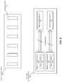
- FIG. 6is a block diagram of an exemplary multi-node compute platform 630 that may be partially or entirely repurposed for hardware acceleration.
- multi-node compute platform 630may be configured with several bays, each of which may house a modular storage device 610 (e.g., an SSD carrier card or a device carrier card), a modular computing device 620 (e.g., a micro-server card), and/or any other suitable type or form of modular node. While FIG. 6 shows multi-node compute platform 630 with four bays, multi-node compute platforms may include any other number bays.
- a modular storage device 610e.g., an SSD carrier card or a device carrier card
- modular computing device 620e.g., a micro-server card
- FIG. 6shows multi-node compute platform 630 with four bays, multi-node compute platforms may include any other number bays.
- Repurposing a multi-node compute platform for hardware accelerationmay involve inserting one or more hardware accelerator expansion cards, such as expansion card 100 , into a compact expansion slot within the multi-node compute platform.
- hardware-accelerator expansion cardssuch as expansion card 100
- expansion sockets 622 of modular computing devices 620may be inserted into either or both of expansion sockets 622 of modular computing devices 620 .
- hardware-accelerator expansion cardsmay be inserted into one or more of expansion sockets 612 in either or both of modular storage devices 610 .
- embodiments of the instant disclosuremay supplement multi-node compute platform 630 with hardware acceleration functionality.
- the disclosed systems and methodsmay enable a data center administrator or automation system to efficiently scale the ability of a multi-node compute platform to handle computationally expensive computing tasks by simply inserting and enabling one or more hardware-acceleration expansion cards into compact expansion sockets within the multi-mode compute platform.
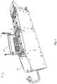
- a multi-node compute platform 700may be dimensioned to accept modular computing devices on one or more sleds, such as sled 702 in FIG. 7 .
- sled 702may include several bays or slots for accepting corresponding trays 703 , each of which may include a modular computing device (e.g., a server card) or a modular storage device (e.g., a carrier or device card, such as an SSD card).
- sled 702may include four separate slots for accepting corresponding trays 703 .
- Each tray 703may include at least one fastening mechanism 704 .
- FIG. 7further illustrates how each tray 703 may hold a modular computing device and/or modular storage device, each of which may include at least one expansion socket into which expansion card 100 may be inserted.
- FIG. 8is a perspective drawing of an expanded multi-node compute platform 800 .
- platform 800may include a set of sleds, such as sled 702 , each of which may accept multiple trays 703 containing modular computing and/or storage devices.
- sled 702may accept multiple trays 703 containing modular computing and/or storage devices.
- the disclosed systems and methodsmay facilitate dramatically improved data center scaling (e.g., scaling that may not involve adding expensive servers and/or that may not require additional space in a data center) for computationally expensive computing tasks.
- data center administratorsmay conveniently scale hardware acceleration resources for complex tasks, such as artificial intelligence inference operations and/or video transcoding operations, by (i) adding one or more expansion cards, such as expansion card 100 , to a single tray (such as tray 703 ) that houses a modular computing and/or storage device, (ii) adding additional trays of modular computing or storage devices to a sled (such as sled 702 ), each of which may include one or more instances of expansion card 100 , (iii) adding additional sleds (such as sled 702 ) to a chassis, each of which may contain additional instances of expansion card 100 , and/or (iv) adding additional chasses and/or server racks, each of which may accept multiple sleds that contain additional instances of expansion card 100 .
- the disclosed systems and methodsmay repurpose or reengineer a multi-node compute platform, and more specifically reengineer a modular computing and/or storage device, which previously may have been used exclusively for mass storage via solid-state drives, to supplement the platform with one or more hardware accelerators.
- Multi-node compute platformsthat are configured in this manner may benefit from the granular scalability provided by compact expansion card specifications, such as the M.2 specification.
- compact expansion card specificationssuch as the M.2 specification.
- the dramatically smaller form factor of compact expansion cardsmay enable a larger number of expansion sockets within the same surface area in comparison to a traditional expansion card such as a PCI EXPRESS expansion card.
- the expansion socket into which expansion card 100 is insertedmay be disposed on an intermediary expansion card.
- the term “intermediary expansion card”generally refers to any expansion card that includes at least one expansion socket dimensioned to accept an additional expansion card in a nested fashion, as discussed further below.
- an exemplary intermediary expansion card 900may include two or more separate expansion sockets 902 , each of which may be dimensioned to each accept an instance of expansion card 100 .
- intermediary expansion card 900may include four separate expansion sockets that may each accept an instance of expansion card 100 .
- the specific number of expansion socketsis merely illustrative, and other examples of intermediary expansion card 900 may include a fewer or greater number of expansion sockets.
- intermediary expansion card 900may include an edge connector having a pinout that conforms to a pinout specification defined for a computing bus to which intermediary expansion card 900 is designed to be connected.
- the pinout of the edge connector of intermediary expansion card 900may conform to the PCI EXPRESS specification.
- intermediary expansion card 900may be coupled to the PCI EXPRESS computing bus of the computing device.
- expansion card 100which may be dimensioned to be inserted into expansion socket 902 of intermediary expansion card 900 , may include an edge connector 110 that includes a pinout that is more compact than a pinout specification defined for the computing bus to which intermediary expansion card 900 is connected.
- edge connector 110 of expansion card 100may conform to a pinout specification defined for the M.2 standard, which is more compact than the pinout specification defined by the PCI EXPRESS standard, such that the pinout of expansion card 100 is more compact than the pinout specification of the computing bus the PCI EXPRESS computing bus) to which expansion card 100 is ultimately connected (via intermediary expansion card 900 ).
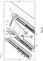
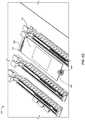
- FIG. 10Ais a perspective view of an example intermediary expansion card 1000 that may include four separate M.2 expansion sockets for accepting four separate M.2 modules, such as instances of expansion card 100 , as discussed above.
- intermediary expansion card 1000may include a heatsink 1010 , which may be lifted to reveal an expansion card 100 , which has previously been inserted into a matching expansion socket 1030 , thereby providing hardware acceleration functionality to intermediary expansion card 1000 .
- FIG. 10Balso provides a plan view of the intermediary expansion card after heatsink 1010 has been completely removed or omitted, thereby fully revealing an example of expansion card 100 , which has been secured within expansion socket 1030 of intermediary expansion card 1000 .
- intermediary expansion card 1000may also include an edge connector 1020 , which in this example may be dimensioned or formatted according to the PCI EXPRESS pinout specification.
- the disclosed systemsmay be scaled along a variety of dimensions, including, for example, by increasing the number of instances of expansion card 100 within a computing device, increasing the number of modular computing devices or modular storage devices (each of which may contain instances of expansion card 100 ), increasing the number of sleds connected within the chassis of a multi-node compute platform (each of which may contain multiple modular computing and/or storage devices), and/or increasing the number of server racks or chasses within a multi-node compute platform.
- a multi-node compute platformmay be designed or retrofitted to scale by inserting and/or activating one mores expansion cards (such as expansion card 100 with hardware accelerator 104 ), thereby conveniently and immediately making these additional resources available to a corresponding program, service, application, and/or process.
- expansion cardssuch as expansion card 100 with hardware accelerator 104
- FIG. 11is a flow diagram of an example computer-implemented method 1200 for performing hardware acceleration.
- the steps shown in FIG. 11may be performed by any suitable computer-executable code and/or computing system, including the system discussed above in the context of FIGS. 6-10 and/or variations or combinations of one or more of the same.
- each of the steps shown in FIG. 11may represent an algorithm whose structure includes and/or is represented by multiple sub-steps, examples of which will be provided in greater detail below.
- one or more of the systems described hereinmay insert an expansion card into an expansion socket of the computing device.
- a data center administrator, data center robot, original equipment manufacturer, and/or automated management systemmay, as part of one or more of the systems shown in FIGS. 6-10 , insert an expansion card 100 into an expansion socket of a computing device, such as a module within a multi-node compute platform (e.g., modular computing device 620 and/or modular storage device 610 ), and/or an intermediary expansion card (such as intermediary expansion card 900 ).
- Expansion card 100may be inserted into the computing device in a variety of ways.
- expansion card 100may be inserted into the computing device in a manner that parallels the insertion of expansion card 100 shown in FIGS. 5A-5C .
- the insertion of expansion card 100 into the computing devicemay involve inserting screw 504 into screw hole 508 to fixedly secure expansion card 100 against a corresponding expansion socket.
- insertion of the expansion card into the computing devicemay involve aligning edge connector 110 with the corresponding expansion socket and then pushing or embedding edge connector 110 securely within the expansion socket.
- inserting expansion card 100 into the expansion socketmay further include inserting expansion card 100 into a socket, such as expansion socket 902 , of an intermediary expansion card such as intermediary expansion card 900 .
- method 1100may further include scaling hardware acceleration capabilities of the computing device by inserting an additional expansion card into an additional expansion slot of the computing device.
- the additional expansion cardmay parallel the structure and/or functionality of expansion card 100 .
- the additional expansion cardmay include a hardware accelerator (e.g., an instance of hardware accelerator 104 ) that further includes application-specific hardware circuitry designed to perform the computing task.
- the additional expansion cardmay also further include an additional edge connector that parallels edge connector 110 , which is discussed further above in connection with FIGS. 4 and 5A-5C .
- the additional edge connector of the additional expansion cardmay include a compact pinout (e.g., according to the M.2 specification) that is more compact than the pinout specification defined for the computing bus (e.g., the PCI EXPRESS computing bus specification).
- a compact pinoute.g., according to the M.2 specification
- the computing buse.g., the PCI EXPRESS computing bus specification
- inserting the additional expansion card into the additional expansion slot to scale hardware acceleration capabilities of the computing devicemay be performed in a variety of ways. In some examples, scaling hardware acceleration capabilities of the computing device may simply involve inserting a single additional expansion card into a corresponding expansion socket, such as expansion socket 612 of modular storage device 610 . In other examples, inserting the additional expansion card may be performed as part of a process for inserting or adding a larger component into the corresponding computing device or system. For example, in the context of FIG. 6 , the additional expansion card may be added to the computing device by adding a modular storage device 610 and/or a modular computing device 620 that further includes the additional expansion card (e.g., includes the additional expansion card inserted into an expansion socket, such as expansion socket 622 ). Similarly, in the example of FIG. 8 , scaling hardware acceleration capabilities of the computing device may further include inserting an additional sled, such as sled 702 , within the corresponding chassis, or rack, of multi-node compute platform 630 .
- one or more of the systems described abovemay offload at least a portion of the computing task from a central processing unit by executing, via application-specific hardware circuitry, the portion of the computing task.
- hardware accelerator 104may, as part of the system of FIGS. 6-10 , offload a portion of the computing task, such as an artificial intelligence inference task and/or a video transcoding task, from a central processing unit by executing, via application-specific hardware circuitry 106 , the portion of the computing task.
- Hardware accelerator 104may offload the portion of the computing task in a variety of ways. In general, hardware accelerator 104 may offload the portion of the computing task in a manner that parallels the discussion of hardware accelerator 104 above in connection with FIGS. 1, 2 and 4 . More specifically, hardware accelerator 104 may perform at least a portion of the computing task itself and, therefore, alleviate one or more central processing units from the burden of performing at least a portion of the computing task. Moreover, as further discussed above, hardware accelerator 104 may perform at least a portion of the computing task in hardware, rather than performing the portion of the computing task in software, and thereby perform the portion of the computing task in a faster and more efficient manner than a central processing unit may be capable of.
- the devices, systems, and methods discussed above in connection with FIGS. 1-11may improve data centers or other computing environments by repurposing compact expansion card technologies to perform hardware acceleration.
- the disclosed systems and methodsmay alleviate or ameliorate a burden on the central processing unit of a domain controller.
- the disclosed hardware acceleration embodimentsmay enable an edge server to efficiently perform one or more computationally expensive computing tasks.
- the disclosed system and methodmay enable technology enterprises to better handle and adapt to expected increases in the demand for infrastructure capable of managing computationally expensive computing tasks.
Landscapes
- Engineering & Computer Science (AREA)
- Theoretical Computer Science (AREA)
- General Engineering & Computer Science (AREA)
- Physics & Mathematics (AREA)
- General Physics & Mathematics (AREA)
- Computer Hardware Design (AREA)
- Human Computer Interaction (AREA)
- Power Engineering (AREA)
- Software Systems (AREA)
- Computing Systems (AREA)
- Mathematical Physics (AREA)
- Microelectronics & Electronic Packaging (AREA)
- Multi Processors (AREA)
- Mounting Components In General For Electric Apparatus (AREA)
- Coupling Device And Connection With Printed Circuit (AREA)
- Printing Elements For Providing Electric Connections Between Printed Circuits (AREA)
- Mounting Of Printed Circuit Boards And The Like (AREA)
Abstract
Description
| Key ID | ID Notched Pins | Provided Interfaces | ||
| A | 8-15 | PCle × 2, USB 2.0, I2C, and | ||
| DP × 4 | ||||
| B | 12-19 | PCle × 2, SATA, USB 2.0, and | ||
| 3.0, audio, UIM, HSIC, SSIC, | ||||
| I2C, and SMBus | ||||
| C | 16-23 | Reserved for future use | ||
| D | 20-27 | Reserved for future use | ||
| E | 24-31 | PCle × 2, USB 2.0, I2C, SDIO, | ||
| UART, and PCM | ||||
| “WiFi/Bluetooth cards” | ||||
| F | 28-35 | Future Memory Interface | ||
| (FMI) | ||||
| G | 39-46 | Reserved for custom use | ||
| (unused in the M.2 | ||||
| specification) | ||||
| H | 43-50 | Reserved for future use | ||
| J | 47-54 | Reserved for future use | ||
| K | 51-58 | Reserved for future use | ||
| L | 55-62 | Reserved for future use | ||
| M | 59-66 | PCle × 4, SATA, and SMBus | ||
| Type ID | Top Side | Bottom Side |
| S1 | 1.20 mm | N/A |
| S2 | 1.35 mm | N/A |
| S3 | 1.50 mm | N/A |
| D1 | 1.20 mm | 1.35 mm |
| D2 | 1.35 mm | 1.35 mm |
| D3 | 1.50 mm | 1.35 mm |
| D4 | 1.50 mm | 0.70 mm |
| D5 | 1.50 mm | 1.50 mm |
Claims (20)
Priority Applications (10)
| Application Number | Priority Date | Filing Date | Title |
|---|---|---|---|
| US15/631,861US10838902B2 (en) | 2017-06-23 | 2017-06-23 | Apparatus, system, and method for performing hardware acceleration via expansion cards |
| PCT/US2017/049276WO2018236408A1 (en) | 2017-06-23 | 2017-08-30 | APPARATUS, SYSTEM AND METHOD FOR IMPLEMENTING HARDWARE ACCELERATION BY EXPANSION CARDS |
| CN201780094104.5ACN111052887B (en) | 2017-06-23 | 2017-08-30 | Apparatus, system and method for performing hardware acceleration via expansion cards |
| JP2019570396AJP7058293B2 (en) | 2017-06-23 | 2017-08-30 | Equipment, systems, and methods for performing hardware acceleration through expansion cards |
| CN202110184573.4ACN112905513A (en) | 2017-06-23 | 2017-08-30 | Apparatus, system, and method for performing hardware acceleration through expansion card |
| KR1020227028611AKR102529851B1 (en) | 2017-06-23 | 2017-08-30 | Apparatus, system, and method for performing hardware acceleration via expansion cards |
| KR1020207000889AKR102436613B1 (en) | 2017-06-23 | 2017-08-30 | Apparatus, system, and method for performing hardware acceleration via expansion cards |
| EP17195956.2AEP3418901A1 (en) | 2017-06-23 | 2017-10-11 | Apparatus, system, and method for performing hardware acceleration via expansion cards |
| US17/075,732US11281615B2 (en) | 2017-06-23 | 2020-10-21 | Apparatus, system, and method for performing hardware acceleration via expansion cards |
| JP2022000354AJP2022058487A (en) | 2017-06-23 | 2022-01-05 | Apparatus, system, and method for performing hardware acceleration via expansion cards |
Applications Claiming Priority (1)
| Application Number | Priority Date | Filing Date | Title |
|---|---|---|---|
| US15/631,861US10838902B2 (en) | 2017-06-23 | 2017-06-23 | Apparatus, system, and method for performing hardware acceleration via expansion cards |
Related Child Applications (1)
| Application Number | Title | Priority Date | Filing Date |
|---|---|---|---|
| US17/075,732ContinuationUS11281615B2 (en) | 2017-06-23 | 2020-10-21 | Apparatus, system, and method for performing hardware acceleration via expansion cards |
Publications (2)
| Publication Number | Publication Date |
|---|---|
| US20180373664A1 US20180373664A1 (en) | 2018-12-27 |
| US10838902B2true US10838902B2 (en) | 2020-11-17 |
Family
ID=64692589
Family Applications (2)
| Application Number | Title | Priority Date | Filing Date |
|---|---|---|---|
| US15/631,861Active2037-09-02US10838902B2 (en) | 2017-06-23 | 2017-06-23 | Apparatus, system, and method for performing hardware acceleration via expansion cards |
| US17/075,732ActiveUS11281615B2 (en) | 2017-06-23 | 2020-10-21 | Apparatus, system, and method for performing hardware acceleration via expansion cards |
Family Applications After (1)
| Application Number | Title | Priority Date | Filing Date |
|---|---|---|---|
| US17/075,732ActiveUS11281615B2 (en) | 2017-06-23 | 2020-10-21 | Apparatus, system, and method for performing hardware acceleration via expansion cards |
Country Status (5)
| Country | Link |
|---|---|
| US (2) | US10838902B2 (en) |
| JP (2) | JP7058293B2 (en) |
| KR (2) | KR102436613B1 (en) |
| CN (2) | CN111052887B (en) |
| WO (1) | WO2018236408A1 (en) |
Cited By (3)
| Publication number | Priority date | Publication date | Assignee | Title |
|---|---|---|---|---|
| US11243817B2 (en)* | 2019-03-29 | 2022-02-08 | Intel Corporation | Technologies for data migration between edge accelerators hosted on different edge locations |
| US11281615B2 (en) | 2017-06-23 | 2022-03-22 | Meta Platforms, Inc. | Apparatus, system, and method for performing hardware acceleration via expansion cards |
| US11681565B2 (en)* | 2018-09-13 | 2023-06-20 | Intel Corporation | Technologies for hierarchical clustering of hardware resources in network function virtualization deployments |
Families Citing this family (69)
| Publication number | Priority date | Publication date | Assignee | Title |
|---|---|---|---|---|
| US10877898B2 (en) | 2017-11-16 | 2020-12-29 | Alibaba Group Holding Limited | Method and system for enhancing flash translation layer mapping flexibility for performance and lifespan improvements |
| US10520994B2 (en)* | 2018-01-31 | 2019-12-31 | Facebook, Inc. | Storage cartridge |
| US10496548B2 (en) | 2018-02-07 | 2019-12-03 | Alibaba Group Holding Limited | Method and system for user-space storage I/O stack with user-space flash translation layer |
| US10831404B2 (en)* | 2018-02-08 | 2020-11-10 | Alibaba Group Holding Limited | Method and system for facilitating high-capacity shared memory using DIMM from retired servers |
| US11379155B2 (en) | 2018-05-24 | 2022-07-05 | Alibaba Group Holding Limited | System and method for flash storage management using multiple open page stripes |
| US10921992B2 (en) | 2018-06-25 | 2021-02-16 | Alibaba Group Holding Limited | Method and system for data placement in a hard disk drive based on access frequency for improved IOPS and utilization efficiency |
| CN111902804B (en) | 2018-06-25 | 2024-03-01 | 阿里巴巴集团控股有限公司 | System and method for managing resources of a storage device and quantifying I/O request costs |
| CN110677250B (en) | 2018-07-02 | 2022-09-02 | 阿里巴巴集团控股有限公司 | Key and certificate distribution method, identity information processing method, device and medium |
| CN110795742B (en) | 2018-08-02 | 2023-05-02 | 阿里巴巴集团控股有限公司 | Metric processing method, device, storage medium and processor for high-speed cryptographic operation |
| CN110795774B (en)* | 2018-08-02 | 2023-04-11 | 阿里巴巴集团控股有限公司 | Measurement method, device and system based on trusted high-speed encryption card |
| US10996886B2 (en) | 2018-08-02 | 2021-05-04 | Alibaba Group Holding Limited | Method and system for facilitating atomicity and latency assurance on variable sized I/O |
| CN110874478B (en) | 2018-08-29 | 2023-05-02 | 阿里巴巴集团控股有限公司 | Key processing method and device, storage medium and processor |
| US11327929B2 (en) | 2018-09-17 | 2022-05-10 | Alibaba Group Holding Limited | Method and system for reduced data movement compression using in-storage computing and a customized file system |
| US10860504B2 (en) | 2018-12-05 | 2020-12-08 | New Century Technologies Ltd. | Peripheral device with embedded video codec functionality |
| US10977122B2 (en) | 2018-12-31 | 2021-04-13 | Alibaba Group Holding Limited | System and method for facilitating differentiated error correction in high-density flash devices |
| US11061735B2 (en) | 2019-01-02 | 2021-07-13 | Alibaba Group Holding Limited | System and method for offloading computation to storage nodes in distributed system |
| US11132291B2 (en) | 2019-01-04 | 2021-09-28 | Alibaba Group Holding Limited | System and method of FPGA-executed flash translation layer in multiple solid state drives |
| US11200337B2 (en) | 2019-02-11 | 2021-12-14 | Alibaba Group Holding Limited | System and method for user data isolation |
| US10970212B2 (en) | 2019-02-15 | 2021-04-06 | Alibaba Group Holding Limited | Method and system for facilitating a distributed storage system with a total cost of ownership reduction for multiple available zones |
| US11061834B2 (en) | 2019-02-26 | 2021-07-13 | Alibaba Group Holding Limited | Method and system for facilitating an improved storage system by decoupling the controller from the storage medium |
| US10891065B2 (en) | 2019-04-01 | 2021-01-12 | Alibaba Group Holding Limited | Method and system for online conversion of bad blocks for improvement of performance and longevity in a solid state drive |
| US10922234B2 (en) | 2019-04-11 | 2021-02-16 | Alibaba Group Holding Limited | Method and system for online recovery of logical-to-physical mapping table affected by noise sources in a solid state drive |
| US10908960B2 (en) | 2019-04-16 | 2021-02-02 | Alibaba Group Holding Limited | Resource allocation based on comprehensive I/O monitoring in a distributed storage system |
| US11169873B2 (en) | 2019-05-21 | 2021-11-09 | Alibaba Group Holding Limited | Method and system for extending lifespan and enhancing throughput in a high-density solid state drive |
| CN110221999A (en)* | 2019-05-23 | 2019-09-10 | 深圳市同泰怡信息技术有限公司 | It is realized based on standard PCIE and supports GPU and M2 SSD extension adapter and implementation method |
| TWI690254B (en)* | 2019-06-10 | 2020-04-01 | 技嘉科技股份有限公司 | Motherboard module and electronic device |
| US10860223B1 (en) | 2019-07-18 | 2020-12-08 | Alibaba Group Holding Limited | Method and system for enhancing a distributed storage system by decoupling computation and network tasks |
| US11074124B2 (en) | 2019-07-23 | 2021-07-27 | Alibaba Group Holding Limited | Method and system for enhancing throughput of big data analysis in a NAND-based read source storage |
| US20210073041A1 (en)* | 2019-09-11 | 2021-03-11 | Baidu Usa Llc | Data transmission with obfuscation using an obfuscation unit for a data processing (dp) accelerator |
| JP7212938B2 (en)* | 2019-09-18 | 2023-01-26 | 株式会社ゴフェルテック | Printed circuit board for function expansion |
| US11126561B2 (en) | 2019-10-01 | 2021-09-21 | Alibaba Group Holding Limited | Method and system for organizing NAND blocks and placing data to facilitate high-throughput for random writes in a solid state drive |
| US11617282B2 (en) | 2019-10-01 | 2023-03-28 | Alibaba Group Holding Limited | System and method for reshaping power budget of cabinet to facilitate improved deployment density of servers |
| US11023020B2 (en)* | 2019-10-30 | 2021-06-01 | Smart Embedded Computing, Inc. | Carrier for one or more solid state drives (SSDs) |
| US11449455B2 (en) | 2020-01-15 | 2022-09-20 | Alibaba Group Holding Limited | Method and system for facilitating a high-capacity object storage system with configuration agility and mixed deployment flexibility |
| TWI709849B (en)* | 2020-01-20 | 2020-11-11 | 技嘉科技股份有限公司 | Heat dissipating assembly and main board module |
| US11379447B2 (en) | 2020-02-06 | 2022-07-05 | Alibaba Group Holding Limited | Method and system for enhancing IOPS of a hard disk drive system based on storing metadata in host volatile memory and data in non-volatile memory using a shared controller |
| US11593240B2 (en) | 2020-02-12 | 2023-02-28 | Samsung Electronics Co., Ltd. | Device and method for verifying a component of a storage device |
| US11150986B2 (en) | 2020-02-26 | 2021-10-19 | Alibaba Group Holding Limited | Efficient compaction on log-structured distributed file system using erasure coding for resource consumption reduction |
| US11200114B2 (en) | 2020-03-17 | 2021-12-14 | Alibaba Group Holding Limited | System and method for facilitating elastic error correction code in memory |
| US11662986B1 (en)* | 2020-03-20 | 2023-05-30 | Meta Platforms, Inc. | Reducing data transfer to machine learning accelerator hardware |
| US11449386B2 (en) | 2020-03-20 | 2022-09-20 | Alibaba Group Holding Limited | Method and system for optimizing persistent memory on data retention, endurance, and performance for host memory |
| US11073873B1 (en)* | 2020-03-25 | 2021-07-27 | Intel Corporation | Electronic device interconnect |
| US11169881B2 (en) | 2020-03-30 | 2021-11-09 | Alibaba Group Holding Limited | System and method for facilitating reduction of complexity and data movement in erasure coding merging on journal and data storage drive |
| US11301173B2 (en) | 2020-04-20 | 2022-04-12 | Alibaba Group Holding Limited | Method and system for facilitating evaluation of data access frequency and allocation of storage device resources |
| US11385833B2 (en) | 2020-04-20 | 2022-07-12 | Alibaba Group Holding Limited | Method and system for facilitating a light-weight garbage collection with a reduced utilization of resources |
| US11281575B2 (en) | 2020-05-11 | 2022-03-22 | Alibaba Group Holding Limited | Method and system for facilitating data placement and control of physical addresses with multi-queue I/O blocks |
| US11494115B2 (en) | 2020-05-13 | 2022-11-08 | Alibaba Group Holding Limited | System method for facilitating memory media as file storage device based on real-time hashing by performing integrity check with a cyclical redundancy check (CRC) |
| US11461262B2 (en) | 2020-05-13 | 2022-10-04 | Alibaba Group Holding Limited | Method and system for facilitating a converged computation and storage node in a distributed storage system |
| US11218165B2 (en) | 2020-05-15 | 2022-01-04 | Alibaba Group Holding Limited | Memory-mapped two-dimensional error correction code for multi-bit error tolerance in DRAM |
| US11556277B2 (en) | 2020-05-19 | 2023-01-17 | Alibaba Group Holding Limited | System and method for facilitating improved performance in ordering key-value storage with input/output stack simplification |
| US11507499B2 (en) | 2020-05-19 | 2022-11-22 | Alibaba Group Holding Limited | System and method for facilitating mitigation of read/write amplification in data compression |
| US11263132B2 (en) | 2020-06-11 | 2022-03-01 | Alibaba Group Holding Limited | Method and system for facilitating log-structure data organization |
| US11422931B2 (en) | 2020-06-17 | 2022-08-23 | Alibaba Group Holding Limited | Method and system for facilitating a physically isolated storage unit for multi-tenancy virtualization |
| US11354200B2 (en) | 2020-06-17 | 2022-06-07 | Alibaba Group Holding Limited | Method and system for facilitating data recovery and version rollback in a storage device |
| US11553625B2 (en)* | 2020-07-23 | 2023-01-10 | Quanta Computer Inc. | Tool-less M.2 device carrier with grounding and thermal flow |
| US11354233B2 (en) | 2020-07-27 | 2022-06-07 | Alibaba Group Holding Limited | Method and system for facilitating fast crash recovery in a storage device |
| US11372774B2 (en) | 2020-08-24 | 2022-06-28 | Alibaba Group Holding Limited | Method and system for a solid state drive with on-chip memory integration |
| US11487465B2 (en) | 2020-12-11 | 2022-11-01 | Alibaba Group Holding Limited | Method and system for a local storage engine collaborating with a solid state drive controller |
| US11734115B2 (en) | 2020-12-28 | 2023-08-22 | Alibaba Group Holding Limited | Method and system for facilitating write latency reduction in a queue depth of one scenario |
| US11416365B2 (en) | 2020-12-30 | 2022-08-16 | Alibaba Group Holding Limited | Method and system for open NAND block detection and correction in an open-channel SSD |
| US11726699B2 (en) | 2021-03-30 | 2023-08-15 | Alibaba Singapore Holding Private Limited | Method and system for facilitating multi-stream sequential read performance improvement with reduced read amplification |
| US11461173B1 (en) | 2021-04-21 | 2022-10-04 | Alibaba Singapore Holding Private Limited | Method and system for facilitating efficient data compression based on error correction code and reorganization of data placement |
| US11476874B1 (en) | 2021-05-14 | 2022-10-18 | Alibaba Singapore Holding Private Limited | Method and system for facilitating a storage server with hybrid memory for journaling and data storage |
| CN113868990B (en)* | 2021-09-24 | 2025-07-29 | 深圳国微芯科技有限公司 | Automatic loading system and method for external module of simulation accelerator |
| CN114416625B (en)* | 2022-01-07 | 2024-10-01 | 北京百度网讯科技有限公司 | Server, extended service card, data processing method and service system |
| KR20240083939A (en) | 2022-12-05 | 2024-06-13 | 삼성에스디에스 주식회사 | Method, apparatus, system and computer program for work deployment in Cloud system including Function Acceleration Card |
| JP7571210B1 (en) | 2023-06-29 | 2024-10-22 | レノボ・シンガポール・プライベート・リミテッド | Connection structure for electronic module |
| KR20250024258A (en) | 2023-08-11 | 2025-02-18 | 삼성에스디에스 주식회사 | Method, apparatus, system and computer program for function notification of Function Acceleration Card in Cloud system |
| KR20250061131A (en) | 2023-10-27 | 2025-05-08 | 삼성에스디에스 주식회사 | Method, apparatus, system and computer program for workload arrangement in cloud system including Function Acceleration Card |
Citations (14)
| Publication number | Priority date | Publication date | Assignee | Title |
|---|---|---|---|---|
| US7595569B2 (en)* | 2004-02-17 | 2009-09-29 | Agere Systems Inc. | Versatile and intelligent power controller |
| US20100076915A1 (en) | 2008-09-25 | 2010-03-25 | Microsoft Corporation | Field-Programmable Gate Array Based Accelerator System |
| US20110066832A1 (en) | 2006-07-28 | 2011-03-17 | Drc Computer Corporation | Configurable Processor Module Accelerator Using A Programmable Logic Device |
| US20120084665A1 (en) | 2004-06-29 | 2012-04-05 | Blake Bookstaff | Method and system for intelligent processing of electronic information with cloud computing |
| US20130111229A1 (en)* | 2011-10-31 | 2013-05-02 | Calxeda, Inc. | Node cards for a system and method for modular compute provisioning in large scalable processor installations |
| US8572614B2 (en)* | 2011-06-30 | 2013-10-29 | International Business Machines Corporation | Processing workloads using a processor hierarchy system |
| US20140192073A1 (en) | 2006-09-25 | 2014-07-10 | Neurala Inc. | Graphic processor based accelerator system and method |
| US20140201303A1 (en)* | 2013-01-17 | 2014-07-17 | Xockets IP, LLC | Network Overlay System and Method Using Offload Processors |
| US20150277935A1 (en)* | 2014-03-29 | 2015-10-01 | Nathaniel L. Desimone | Techniques for adaptive interface support |
| US20150294434A1 (en) | 2014-04-09 | 2015-10-15 | LEAP Computing, Inc. | Mxm graphics card adapter |
| US20160364271A1 (en)* | 2015-06-09 | 2016-12-15 | Microsoft Technology Licensing, Llc | Independently networkable hardware accelerators for increased workflow optimization |
| US20170139629A1 (en)* | 2015-11-16 | 2017-05-18 | International Business Machines Corporation | Access processor |
| US20170308499A1 (en)* | 2016-04-21 | 2017-10-26 | LDA Technologies Ltd | System and Method for Repurposing Communication Ports |
| US20180081804A1 (en)* | 2016-09-19 | 2018-03-22 | Qualcomm Incorporated | Dynamic Input/Output Coherency |
Family Cites Families (20)
| Publication number | Priority date | Publication date | Assignee | Title |
|---|---|---|---|---|
| US6976090B2 (en)* | 2000-04-20 | 2005-12-13 | Actona Technologies Ltd. | Differentiated content and application delivery via internet |
| US20020174290A1 (en)* | 2001-05-15 | 2002-11-21 | Wu Kun Ho | Memory accelerator, acceleration method and associated interface card and motherboard |
| US7710741B1 (en)* | 2005-05-03 | 2010-05-04 | Nvidia Corporation | Reconfigurable graphics processing system |
| JP2007328461A (en)* | 2006-06-06 | 2007-12-20 | Matsushita Electric Ind Co Ltd | Asymmetric multiprocessor |
| US8117137B2 (en)* | 2007-04-19 | 2012-02-14 | Microsoft Corporation | Field-programmable gate array based accelerator system |
| US8219750B2 (en)* | 2008-06-30 | 2012-07-10 | Pivot3 | Method and system for execution of applications in conjunction with distributed RAID |
| US8364481B2 (en)* | 2008-07-02 | 2013-01-29 | Google Inc. | Speech recognition with parallel recognition tasks |
| KR20100037959A (en)* | 2008-10-02 | 2010-04-12 | 주식회사 인프라넷 | Virtualized computing accelerator and program download method of based virtualized computing |
| US8894020B2 (en)* | 2011-02-28 | 2014-11-25 | Harvey J. Rosener | Block module for model train layout control |
| WO2014110281A1 (en)* | 2013-01-11 | 2014-07-17 | Db Networks, Inc. | Systems and methods for detecting and mitigating threats to a structured data storage system |
| CN106649345A (en)* | 2015-10-30 | 2017-05-10 | 微软技术许可有限责任公司 | Automatic session creator for news |
| TWM539644U (en)* | 2016-11-15 | 2017-04-11 | 映奧股份有限公司 | Install multiple M. 2 solid state storage module |
| CN106776461A (en)* | 2017-01-13 | 2017-05-31 | 算丰科技(北京)有限公司 | Data processing equipment and server |
| EP3507675A4 (en)* | 2017-01-28 | 2020-02-12 | Hewlett-Packard Development Company, L.P. | CUSTOMIZABLE CONNECTORS WITH EXTERNAL I / O PORT |
| EP3418901A1 (en) | 2017-06-23 | 2018-12-26 | Facebook, Inc. | Apparatus, system, and method for performing hardware acceleration via expansion cards |
| US10838902B2 (en) | 2017-06-23 | 2020-11-17 | Facebook, Inc. | Apparatus, system, and method for performing hardware acceleration via expansion cards |
| US10488893B1 (en)* | 2018-05-23 | 2019-11-26 | Dell Products L.P. | Expansion module system |
| US10729030B1 (en)* | 2018-08-28 | 2020-07-28 | Facebook, Inc. | Apparatuses, systems, and methods for integrating hardware accelerators into computing systems |
| US10477707B1 (en)* | 2018-08-30 | 2019-11-12 | Facebook, Inc. | Apparatuses, systems, and methods for performing hardware acceleration via dual-compact-form-factor expansion cards |
| US11073873B1 (en)* | 2020-03-25 | 2021-07-27 | Intel Corporation | Electronic device interconnect |
- 2017
- 2017-06-23USUS15/631,861patent/US10838902B2/enactiveActive
- 2017-08-30WOPCT/US2017/049276patent/WO2018236408A1/ennot_activeCeased
- 2017-08-30KRKR1020207000889Apatent/KR102436613B1/enactiveActive
- 2017-08-30CNCN201780094104.5Apatent/CN111052887B/enactiveActive
- 2017-08-30KRKR1020227028611Apatent/KR102529851B1/enactiveActive
- 2017-08-30CNCN202110184573.4Apatent/CN112905513A/enactivePending
- 2017-08-30JPJP2019570396Apatent/JP7058293B2/enactiveActive
- 2020
- 2020-10-21USUS17/075,732patent/US11281615B2/enactiveActive
- 2022
- 2022-01-05JPJP2022000354Apatent/JP2022058487A/enactivePending
Patent Citations (15)
| Publication number | Priority date | Publication date | Assignee | Title |
|---|---|---|---|---|
| US7595569B2 (en)* | 2004-02-17 | 2009-09-29 | Agere Systems Inc. | Versatile and intelligent power controller |
| US20120084665A1 (en) | 2004-06-29 | 2012-04-05 | Blake Bookstaff | Method and system for intelligent processing of electronic information with cloud computing |
| US20110066832A1 (en) | 2006-07-28 | 2011-03-17 | Drc Computer Corporation | Configurable Processor Module Accelerator Using A Programmable Logic Device |
| US20140192073A1 (en) | 2006-09-25 | 2014-07-10 | Neurala Inc. | Graphic processor based accelerator system and method |
| US20100076915A1 (en) | 2008-09-25 | 2010-03-25 | Microsoft Corporation | Field-Programmable Gate Array Based Accelerator System |
| US8572614B2 (en)* | 2011-06-30 | 2013-10-29 | International Business Machines Corporation | Processing workloads using a processor hierarchy system |
| US20130111229A1 (en)* | 2011-10-31 | 2013-05-02 | Calxeda, Inc. | Node cards for a system and method for modular compute provisioning in large scalable processor installations |
| US20140201303A1 (en)* | 2013-01-17 | 2014-07-17 | Xockets IP, LLC | Network Overlay System and Method Using Offload Processors |
| US20150277935A1 (en)* | 2014-03-29 | 2015-10-01 | Nathaniel L. Desimone | Techniques for adaptive interface support |
| US20150294434A1 (en) | 2014-04-09 | 2015-10-15 | LEAP Computing, Inc. | Mxm graphics card adapter |
| US20160364271A1 (en)* | 2015-06-09 | 2016-12-15 | Microsoft Technology Licensing, Llc | Independently networkable hardware accelerators for increased workflow optimization |
| WO2016200844A1 (en) | 2015-06-09 | 2016-12-15 | Microsoft Technology Licensing, Llc | Independently networkable hardware accelerators for increased workflow optimization |
| US20170139629A1 (en)* | 2015-11-16 | 2017-05-18 | International Business Machines Corporation | Access processor |
| US20170308499A1 (en)* | 2016-04-21 | 2017-10-26 | LDA Technologies Ltd | System and Method for Repurposing Communication Ports |
| US20180081804A1 (en)* | 2016-09-19 | 2018-03-22 | Qualcomm Incorporated | Dynamic Input/Output Coherency |
Non-Patent Citations (3)
| Title |
|---|
| Wikipedia; Edge connector; https://en.wikipedia.org/w/index.php?title=Edge_connector&oldid=736591535; as accessed Aug. 3, 2017 (dated Aug. 28, 2016). |
| Wikipedia; M.2; https://en.wikipedia.org/w/index.php?title=M.2&oldid=785692082; as accessed Aug. 3, 2017 (dated Jun. 24, 2017). |
| Wikipedia; Pinout; https://en.wikipedia.org/w/index.php?title=Pinout&oldid=780226921; as accessed Aug. 3, 2017 (dated May 13, 2017). |
Cited By (6)
| Publication number | Priority date | Publication date | Assignee | Title |
|---|---|---|---|---|
| US11281615B2 (en) | 2017-06-23 | 2022-03-22 | Meta Platforms, Inc. | Apparatus, system, and method for performing hardware acceleration via expansion cards |
| US11681565B2 (en)* | 2018-09-13 | 2023-06-20 | Intel Corporation | Technologies for hierarchical clustering of hardware resources in network function virtualization deployments |
| US12093746B2 (en) | 2018-09-13 | 2024-09-17 | Intel Corporation | Technologies for hierarchical clustering of hardware resources in network function virtualization deployments |
| US11243817B2 (en)* | 2019-03-29 | 2022-02-08 | Intel Corporation | Technologies for data migration between edge accelerators hosted on different edge locations |
| US20220237033A1 (en)* | 2019-03-29 | 2022-07-28 | Intel Corporation | Technologies for data migration between edge accelerators hosted on different edge locations |
| US11972298B2 (en)* | 2019-03-29 | 2024-04-30 | Intel Corporation | Technologies for data migration between edge accelerators hosted on different edge locations |
Also Published As
| Publication number | Publication date |
|---|---|
| JP7058293B2 (en) | 2022-04-21 |
| US20180373664A1 (en) | 2018-12-27 |
| CN111052887A (en) | 2020-04-21 |
| CN111052887B (en) | 2021-02-05 |
| US11281615B2 (en) | 2022-03-22 |
| KR102436613B1 (en) | 2022-08-29 |
| KR20200011548A (en) | 2020-02-03 |
| JP2020529647A (en) | 2020-10-08 |
| US20210056066A1 (en) | 2021-02-25 |
| CN112905513A (en) | 2021-06-04 |
| KR102529851B1 (en) | 2023-05-09 |
| WO2018236408A1 (en) | 2018-12-27 |
| JP2022058487A (en) | 2022-04-12 |
| KR20220123131A (en) | 2022-09-05 |
Similar Documents
| Publication | Publication Date | Title |
|---|---|---|
| US11281615B2 (en) | Apparatus, system, and method for performing hardware acceleration via expansion cards | |
| US10729030B1 (en) | Apparatuses, systems, and methods for integrating hardware accelerators into computing systems | |
| US10477707B1 (en) | Apparatuses, systems, and methods for performing hardware acceleration via dual-compact-form-factor expansion cards | |
| US10034407B2 (en) | Storage sled for a data center | |
| US9197629B2 (en) | Remote direct memory access authentication of a device | |
| US20070204332A1 (en) | Authentication of baseboard management controller users in a blade server system | |
| US10013563B2 (en) | Systems and methods for binding a removable cryptoprocessor to an information handling system | |
| US20170262396A1 (en) | Open Compute Project Network Card Converted to PCIe Riser | |
| US11921551B2 (en) | Card retention mechanism in an information handling system | |
| EP3418901A1 (en) | Apparatus, system, and method for performing hardware acceleration via expansion cards | |
| US20200026531A1 (en) | Apparatus and Method for Dynamic Modification of Machine Branding of Information Handling Systems Based on Hardware Inventory | |
| US20190004816A1 (en) | Systems and methods for heterogeneous system on a chip servers | |
| US20180278472A1 (en) | System and method for performing mass renaming of list of items at run-time with variable differentiation factor | |
| CN102063341A (en) | high density server | |
| US11651077B2 (en) | Systems and methods for providing secured boot and scan for devices with limited access | |
| US11983668B2 (en) | Systems and methods for inventory collection in a management controller | |
| CN114003661B (en) | Offline data entry method, device, electronic device and storage medium | |
| US11841750B2 (en) | Interchangeable labeling strip in chassis hem | |
| US20250293462A1 (en) | Fine alignment adapter for aligning an information handling resource with a connector | |
| US20250272450A1 (en) | Systems and methods for automated cable diagram generation in an information handling system | |
| US12267959B2 (en) | System and method for reversible connection of interchangeable components | |
| US12122079B2 (en) | Hidden runner injection mold structure | |
| US8051153B2 (en) | Switch apparatus for a remote boot sequence of a network device | |
| US20240134925A1 (en) | Software-defined fru |
Legal Events
| Date | Code | Title | Description |
|---|---|---|---|
| AS | Assignment | Owner name:FACEBOOK, INC., CALIFORNIA Free format text:ASSIGNMENT OF ASSIGNORS INTEREST;ASSIGNOR:VIJAYRAO, NARSING KRISHNA;REEL/FRAME:042802/0220 Effective date:20170623 | |
| STPP | Information on status: patent application and granting procedure in general | Free format text:RESPONSE TO NON-FINAL OFFICE ACTION ENTERED AND FORWARDED TO EXAMINER | |
| STPP | Information on status: patent application and granting procedure in general | Free format text:NON FINAL ACTION MAILED | |
| STPP | Information on status: patent application and granting procedure in general | Free format text:RESPONSE TO NON-FINAL OFFICE ACTION ENTERED AND FORWARDED TO EXAMINER | |
| STPP | Information on status: patent application and granting procedure in general | Free format text:FINAL REJECTION MAILED | |
| STPP | Information on status: patent application and granting procedure in general | Free format text:ADVISORY ACTION MAILED | |
| STPP | Information on status: patent application and granting procedure in general | Free format text:DOCKETED NEW CASE - READY FOR EXAMINATION | |
| STPP | Information on status: patent application and granting procedure in general | Free format text:NON FINAL ACTION MAILED | |
| STPP | Information on status: patent application and granting procedure in general | Free format text:RESPONSE TO NON-FINAL OFFICE ACTION ENTERED AND FORWARDED TO EXAMINER | |
| STPP | Information on status: patent application and granting procedure in general | Free format text:PUBLICATIONS -- ISSUE FEE PAYMENT RECEIVED | |
| STPP | Information on status: patent application and granting procedure in general | Free format text:PUBLICATIONS -- ISSUE FEE PAYMENT VERIFIED | |
| STCF | Information on status: patent grant | Free format text:PATENTED CASE | |
| AS | Assignment | Owner name:META PLATFORMS, INC., CALIFORNIA Free format text:CHANGE OF NAME;ASSIGNOR:FACEBOOK, INC.;REEL/FRAME:058871/0336 Effective date:20211028 | |
| MAFP | Maintenance fee payment | Free format text:PAYMENT OF MAINTENANCE FEE, 4TH YEAR, LARGE ENTITY (ORIGINAL EVENT CODE: M1551); ENTITY STATUS OF PATENT OWNER: LARGE ENTITY Year of fee payment:4 |