US10838209B2 - Head mounted imaging apparatus with curved lenslet array - Google Patents
Head mounted imaging apparatus with curved lenslet arrayDownload PDFInfo
- Publication number
- US10838209B2 US10838209B2US15/538,122US201615538122AUS10838209B2US 10838209 B2US10838209 B2US 10838209B2US 201615538122 AUS201615538122 AUS 201615538122AUS 10838209 B2US10838209 B2US 10838209B2
- Authority
- US
- United States
- Prior art keywords
- lenslet array
- curved mirror
- light
- image
- real image
- Prior art date
- Legal status (The legal status is an assumption and is not a legal conclusion. Google has not performed a legal analysis and makes no representation as to the accuracy of the status listed.)
- Active, expires
Links
- 238000003384imaging methodMethods0.000titleclaimsabstractdescription12
- 239000000758substrateSubstances0.000claimsdescription10
- 238000000034methodMethods0.000claimsdescription4
- 238000005286illuminationMethods0.000claims1
- 230000003287optical effectEffects0.000description20
- 210000001747pupilAnatomy0.000description19
- 230000003190augmentative effectEffects0.000description5
- 238000013461designMethods0.000description5
- 239000011521glassSubstances0.000description3
- 238000013507mappingMethods0.000description3
- 230000004075alterationEffects0.000description2
- 230000005540biological transmissionEffects0.000description2
- 230000003750conditioning effectEffects0.000description2
- 230000008878couplingEffects0.000description2
- 238000010168coupling processMethods0.000description2
- 238000005859coupling reactionMethods0.000description2
- 238000010586diagramMethods0.000description2
- 239000004973liquid crystal related substanceSubstances0.000description2
- 230000004044responseEffects0.000description2
- XUIMIQQOPSSXEZ-UHFFFAOYSA-NSiliconChemical compound[Si]XUIMIQQOPSSXEZ-UHFFFAOYSA-N0.000description1
- 230000009471actionEffects0.000description1
- 238000005452bendingMethods0.000description1
- 239000011436cobSubstances0.000description1
- 230000000694effectsEffects0.000description1
- 238000005516engineering processMethods0.000description1
- 230000004424eye movementEffects0.000description1
- 230000001815facial effectEffects0.000description1
- 238000012986modificationMethods0.000description1
- 230000004048modificationEffects0.000description1
- 238000012634optical imagingMethods0.000description1
- 238000012552reviewMethods0.000description1
- 239000004065semiconductorSubstances0.000description1
- 229910052710siliconInorganic materials0.000description1
- 239000010703siliconSubstances0.000description1
- 230000005236sound signalEffects0.000description1
- 230000008685targetingEffects0.000description1
- 230000000007visual effectEffects0.000description1
Images


Classifications
- G—PHYSICS
- G02—OPTICS
- G02B—OPTICAL ELEMENTS, SYSTEMS OR APPARATUS
- G02B27/00—Optical systems or apparatus not provided for by any of the groups G02B1/00 - G02B26/00, G02B30/00
- G02B27/01—Head-up displays
- G02B27/017—Head mounted
- G02B27/0172—Head mounted characterised by optical features
- G—PHYSICS
- G02—OPTICS
- G02B—OPTICAL ELEMENTS, SYSTEMS OR APPARATUS
- G02B27/00—Optical systems or apparatus not provided for by any of the groups G02B1/00 - G02B26/00, G02B30/00
- G02B27/01—Head-up displays
- G02B27/017—Head mounted
- G02B27/0176—Head mounted characterised by mechanical features
- G—PHYSICS
- G02—OPTICS
- G02B—OPTICAL ELEMENTS, SYSTEMS OR APPARATUS
- G02B3/00—Simple or compound lenses
- G02B3/0006—Arrays
- G—PHYSICS
- G02—OPTICS
- G02B—OPTICAL ELEMENTS, SYSTEMS OR APPARATUS
- G02B27/00—Optical systems or apparatus not provided for by any of the groups G02B1/00 - G02B26/00, G02B30/00
- G02B27/01—Head-up displays
- G02B27/0101—Head-up displays characterised by optical features
- G02B2027/0123—Head-up displays characterised by optical features comprising devices increasing the field of view
- G—PHYSICS
- G02—OPTICS
- G02B—OPTICAL ELEMENTS, SYSTEMS OR APPARATUS
- G02B27/00—Optical systems or apparatus not provided for by any of the groups G02B1/00 - G02B26/00, G02B30/00
- G02B27/01—Head-up displays
- G02B27/0101—Head-up displays characterised by optical features
- G02B2027/0145—Head-up displays characterised by optical features creating an intermediate image
Definitions
- This inventiongenerally relates to electronic displays and more particularly relates to a wearable electronic display that forms a virtual image.
- Head-Mounted Displayswhich include near eye displays in a form resembling conventional eyeglasses or sunglasses, are being developed for a range of diverse uses, including military, commercial, industrial, fire-fighting, and entertainment applications. For many of these applications, there is particular value in forming a virtual image that can be visually superimposed over the real-world image that lies in the field of view of the HMD user.
- HMD opticsmust meet a number of basic requirements for viewer acceptance, including the following:
- the eyeboxrelates to the volume within which the eye of the observer can comfortably view the image.
- the size of the eyeboxdepends in part on the length of the path of the light from the image source to where the image is viewed and image source size, and in part on the divergence of the image source and/or the collimation of the light after its emission by the image source.
- the desirable size of the eye boxdepends largely on the quality of viewing experience that is desired from the display.
- HMD designsmust also address practical factors such as variable facial geometry, acceptable form factor with expectations of reduced size for wearing comfort, weight, and cost, and ease of use.
- a goal for most HMD systemsis to make the imaging/relay system as compact as possible; however, when using conventional optics, there are basic limits.
- the output of the optic systemmust have a pupil that is large enough to support a reasonably sized virtual image and also allow for some movement of the eye.
- IODintraocular distance
- a binocular systemthere is also the issue of varying intraocular distance (IOD) among different users and the need for the output pupil of the optical system to allow for this.
- IODintraocular distance
- Especially for the case of wide FOV of 60 degrees of greater, eye movement, user variations of IOD, and human pupil sizemay require horizontal output pupil size of 20 mm or greater.
- compact HMD's having short optical pathsimpose significant challenges on the divergence of the collimated virtual image.
- wide FOV compact HMD'soften require the use of fast optics which can be bulky, complex, costly, and exhibit spherical and other aberrations.
- ball lenses forming the image located at the focal plane of by a spherical mirrorrequires a large beam divergence to achieve the large output pupils given the short eye distances.
- ball lenses or other monocentric optics used at high diverging anglesexhibit significant spherical aberration which degrades the virtual image and ultimately compromises the required image resolution for high definition content.
- the prism-like geometries of the semitransmissive elementscomplicate their use in augmented reality configurations, since their curved or angled surfaces refract light from the direct “see-through” or ambient environment. Therefore, in order for these systems to be used in augmented reality modes, either corrective optics or digital imagers must be used, increasing cost, size, and weight.
- embodiments of the present disclosureprovide an enlarged pupil size presenting high resolution wide FOV content to viewers having wide range of IOD's with minimal or no optical adjustment required.
- a head-mounted imaging apparatusthat comprises:
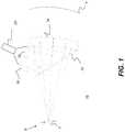
- FIG. 1is a schematic side view of the optical apparatus components for providing an image to one eye of the observer.
- FIG. 2is a schematic side view that shows how the lenslet array expands the pupil size.
- FIG. 3shows field curvature applied to the lenslet array.
- FIG. 4is a schematic diagram that shows a general principle used for pupil expansion.
- FIG. 5is a perspective view that shows forming an image for one eye.
- FIG. 6is a perspective view from the viewing side that shows components of a head-mounted apparatus for providing a virtual image to the observer.
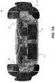
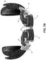
- FIGS. 7A, 7B, and 7Care front perspective views that show components of a head-mounted apparatus for providing a virtual image to the observer.
- first”, “second”, and so ondo not necessarily denote any ordinal, sequential, or priority relation, but are simply used to more clearly distinguish one element or set of elements from another, unless specified otherwise.
- top and bottomdo not necessarily designate spatial position but provide relative information about a structure, such as to distinguish opposing surfaces of a planar (flat) waveguide.
- viewerIn the context of the present disclosure, the terms “viewer”, “operator”, “observer”, and “user” are considered to be equivalent and refer to the person who wears the HMD viewing device.
- the term “energizable”relates to a device or set of components that perform an indicated function upon receiving power and, optionally, upon receiving an enabling signal.
- actuablehas its conventional meaning, relating to a device or component that is capable of effecting an action in response to a stimulus, such as in response to an electrical signal, for example.
- setrefers to a non-empty set, as the concept of a collection of elements or members of a set is widely understood in elementary mathematics.
- subsetunless otherwise explicitly stated, is used herein to refer to a non-empty proper subset, that is, to a subset of the larger set, having one or more members.
- a subsetmay comprise the complete set S.
- a “proper subset” of set Sis strictly contained in set S and excludes at least one member of set S.
- obliquemeans at an angle that is not an integer multiple of 90 degrees.
- Two lines, linear structures, or planes, for example,are considered to be oblique with respect to each other if they diverge from or converge toward each other at an angle that is at least about 5 degrees or more away from parallel, or at least about 5 degrees or more away from orthogonal.
- the term “coupled”is intended to indicate a physical association, connection, relation, or linking, between two or more components, such that the disposition of one component affects the spatial disposition of a component to which it is coupled.
- two componentsneed not be in direct contact, but can be linked through one or more intermediary components.
- a component for optical couplingallows light energy to be input to, or output from, an optical apparatus.
- beam expanderand “pupil expander” are considered to be synonymous, used interchangeably herein.
- an optical systemcan produce a virtual image display.
- a virtual imageis not formed on a display surface. That is, if a display surface were positioned at the perceived location of a virtual image, no image would be formed on that surface.
- a virtual image displayhas a number of inherent advantages for an augmented reality display. For example, the apparent size of a virtual image is not limited by the size or location of a display surface. Additionally, the source object for a virtual image may be small; a magnifying glass, as a simple example, provides a virtual image of its object. In comparison with systems that project a real image, a more realistic viewing experience can be provided by forming a virtual image that appears to be some distance away. Providing a virtual image also obviates any need to compensate for screen artifacts, as may be necessary when projecting a real image.
- Embodiments of the present disclosureprovide an optical system for providing a virtual image with an enlarged view pupil.
- the image space f/# of a projectordepends on the distance to the image divided by the diameter of the system stop (approximated by the aperture size of the last optic).
- a projector at greater than f/2.6 over a reasonable distancewould be too bulky for an HMD system.
- a more compact projector with an exit aperture diameter of 8 mm or less projecting at a >f/3.5 distancedoes not properly fill the aperture.
- the challenge for system opticsis to provide an optical solution that provides an increased f/# without appreciably adding to the bulk of the optical system.
- FIG. 1shows components of an imaging apparatus 10 for providing a virtual image to one eye at an exit pupil E that lies within an eyebox B that is defined between the two generally parallel lines shown and that defines where the image is visible to the observer.
- a projector 20projects an image to a lenslet array 30 at an image plane, forming a real image that is at or near the lenslet array 30 .
- Lenslet array 30acts as a diffuser in transmission of light, as opposed to solutions that utilize a reflective diffuser.
- the substrate that provides lenslet array 30is curved to reduce Petzval curvature in subsequent light handling.
- Lenslet array 30is disposed at one focal length from a spherical curved mirror 34 .
- lenslet array 30curvature extends into the page; an edge 36 is substantially parallel to the page surface and lies outside the page surface.
- Lenslet array 30expands the effective beam width, and thus the f/# of the projected beam from projector 20 .
- a beam splitter 32directs the expanded beam toward spherical curved mirror 34 that forms a magnified virtual image V by redirecting the light toward exit pupil E.
- Virtual image Vappears to lie beyond the outer edge of curved mirror 34 .
- Eye box Bis sufficiently sized to allow multiple pupil positions.
- the surface of curved mirror 34is substantially spherical, but may have curvature that is not spherical.
- Curved mirror 34can be partly transmissive, such as to allow the observer to see at least a portion of the actual ambient environment for augmented reality applications.
- An optical shuttersuch as a mechanical shutter or light valve such as an LCD (liquid crystal device), can optionally be provided to control light transmission through the curved mirror 34 and to block or transmit light from the ambient environment.
- FIG. 2shows, with dimensions exaggerated for emphasis, how lenslet array 30 expands the beam width to provide a larger f/# within the optical system.
- lenslet array 30expands the beam width to provide a larger f/# within the optical system.
- FIG. 4is a schematic diagram that shows a principle of operation for the imaging system.
- Projector 20forms a real image on lenslet array 30 , which operates to spread the light from each pixel.
- the magnification systemrepresented schematically by a lens L in FIG. 4 but performed by curved mirror 34 in the optical imaging apparatus 10 of the present disclosure, then provides the light that forms the virtual image for the observer's eye.
- Light at the exit pupilis at least at about f/4.
- FIG. 5is a view of a portion of a portion of the optical system that shows the relative position of the eye box B of the observer, in dashed outline.
- FIG. 6is a rear perspective view that shows optical components in a head-mounted device (HMD) 50 .
- FIGS. 7A, 7B, and 7Cshow views from in front of the observer.
- Light-conditioning optics 40include one or more optical elements that direct and shape the image-bearing light from the projector in order to form a real image plane.
- Light conditioning optics 40guide light from projector 20 and through curved lenslet array 30 to beam splitter 32 .
- the front views of FIGS. 7A, 7B, and 7Cshow curved mirror 34 that forms the virtual image from the real image that is projected onto curved lenslet array 30 .
- Headphones 60provide audio signal output.
- the lenslet arraycan be provided on a glass substrate or on a plastic substrate. Curvature of the lenslet array can be provided by permanently bending the array or by mounting the array in a frame that causes the array to bend to an appropriate shape.
- the projectorcan use a solid-state light source, such as a light-emitting diode (LED) coupled with one or more light modulating display panels such as liquid crystal on silicon (LCOS) or digital light processor (DLP), for example.
- Light-conditioning optics 40can include lenses, mirrors, prism-based waveguides, or other devices to direct, shape, and modify the image-bearing light from the projector 20 to lenslet array 30 . Image field or Petzval curvature can be achieved with proper design of all elements of light conditioning optics 40 .
- Embodiments of the present disclosureallow the use of a small projector device for displaying a virtual image to the observer with a large eye box.
Landscapes
- Physics & Mathematics (AREA)
- General Physics & Mathematics (AREA)
- Optics & Photonics (AREA)
Abstract
Description
- (i) sufficient eye relief or eye clearance. The eye relief range is defined based on viewer comfort and the optical configuration of the human eye itself. In practice, the distance between the last optical surface of the HMD optics and the viewer's eye is preferably above about 20 mm.
- (ii) appropriate pupil size. Pupil size requirements are based on physiological differences in viewer face structure as well as on gaze redirection during viewing. A pupil size of at least about 10 mm diameter has been found to be desirable.
- (iii) field of view. A wide field of view is preferable. For many visual tasks, such as targeting and object recognition, a field of view (FOV) approaching about 50 degrees is considered to be desirable.
- (iv) brightness. The virtual image that is generated should have sufficient brightness for good visibility and viewer comfort.
- a projector that is energizable to project image-bearing light;
- a light-conditioning element that directs and shapes the image-bearing light from the projector to form a real image plane;
- a lenslet array positioned adjacent to the real image plane and optically disposed at substantially one focal length away from a curved mirror, wherein the surface of the curved mirror is substantially spherical; and
- a beamsplitter in the path of light from the real image at the lenslet array and disposed to direct at least a portion of the light from the real image toward the curved mirror;
- wherein the curved mirror directs light from the beamsplitter to form a virtual image for an observer who wears the head-mounted imaging apparatus.
- (i) Mapping of image pixels to lenslets. A 1:1 mapping of image pixels to lenslets is particularly advantageous. For this arrangement, the lenslet diameter is preferably about the size of an individual image pixel. A fewer than 1:1 mapping can alternately be provided.
- (ii) Projector focus.
Projector 20 focus near the focal plane of thelenslet array 30 is advantageous. A focal plane FP ofprojector 20 is shown by a dashed line inFIG. 2 . AsFIG. 2 suggests,projector 20 focus can be slightly offset, so that the projected image is focused along or within the substrate of thelenslet array 30 but slightly behind the focal points F1 of theindividual lenslets 38 in the optical path. In this arrangement, the lenslet array is considered to be positioned adjacent to the image plane. - (iii) Enlarged angle. The projected light from
projector 20 is typically in the range of about f/5 or higher, and can range from f/6 to f/10. The light expanded bylenslet array 30 is at about f/3.5 or lower. - (iv) Lenslet shape.
Lenslets 38 inarray 30 can be convex, concave, or other suitable shape. - (v)
Lenslet array 30 curvature.FIG. 3 showslenslet array 30 curvature relative to a spherical curvature S. As shown inFIG. 3 ,lenslet array 30 is curved about a single axis A; over a relatively short distance this curvature can closely approximate spherical curvature S. The ideal curvature for thelenslet array 30 would be spherical; however, cylindrical curvature provides a reasonable alternative, as shown. This helps to reduce Petzval curvature effects. Curvatures of the image plane need not exactly match the Petzval curvature of the lens, but should be at least within about 1 Diopter, within a range that can be accommodated by a significant portion of the observer population.
Claims (9)
Priority Applications (1)
| Application Number | Priority Date | Filing Date | Title |
|---|---|---|---|
| US15/538,122US10838209B2 (en) | 2015-01-06 | 2016-01-06 | Head mounted imaging apparatus with curved lenslet array |
Applications Claiming Priority (3)
| Application Number | Priority Date | Filing Date | Title |
|---|---|---|---|
| US201562100355P | 2015-01-06 | 2015-01-06 | |
| PCT/US2016/012376WO2016112128A1 (en) | 2015-01-06 | 2016-01-06 | Head mounted imaging apparatus with curved lenslet array |
| US15/538,122US10838209B2 (en) | 2015-01-06 | 2016-01-06 | Head mounted imaging apparatus with curved lenslet array |
Publications (2)
| Publication Number | Publication Date |
|---|---|
| US20180003977A1 US20180003977A1 (en) | 2018-01-04 |
| US10838209B2true US10838209B2 (en) | 2020-11-17 |
Family
ID=56356396
Family Applications (1)
| Application Number | Title | Priority Date | Filing Date |
|---|---|---|---|
| US15/538,122Active2036-05-16US10838209B2 (en) | 2015-01-06 | 2016-01-06 | Head mounted imaging apparatus with curved lenslet array |
Country Status (5)
| Country | Link |
|---|---|
| US (1) | US10838209B2 (en) |
| EP (1) | EP3243098B1 (en) |
| JP (1) | JP6797799B2 (en) |
| CN (1) | CN107111142B (en) |
| WO (1) | WO2016112128A1 (en) |
Families Citing this family (17)
| Publication number | Priority date | Publication date | Assignee | Title |
|---|---|---|---|---|
| US9759919B2 (en)* | 2015-01-05 | 2017-09-12 | Microsoft Technology Licensing, Llc | Virtual image display with curved light path |
| US11508257B2 (en) | 2017-03-07 | 2022-11-22 | 8259402 Canada Inc. | Method to control a virtual image in a display |
| US10401954B2 (en) | 2017-04-17 | 2019-09-03 | Intel Corporation | Sensory enhanced augmented reality and virtual reality device |
| CN109521506B (en)* | 2017-09-20 | 2022-08-12 | 苏州苏大维格科技集团股份有限公司 | Nano lens, near-eye display method and near-eye display device |
| US10768431B2 (en) | 2017-12-20 | 2020-09-08 | Aperture In Motion, LLC | Light control devices and methods for regional variation of visual information and sampling |
| US10175490B1 (en) | 2017-12-20 | 2019-01-08 | Aperture In Motion, LLC | Light control devices and methods for regional variation of visual information and sampling |
| CN109963142B (en)* | 2017-12-25 | 2024-04-26 | 广东虚拟现实科技有限公司 | Visual display system and method, and head mounted display device |
| US11477419B2 (en) | 2018-05-17 | 2022-10-18 | Nokia Technologies Oy | Apparatus and method for image display |
| JP7447628B2 (en)* | 2020-03-31 | 2024-03-12 | セイコーエプソン株式会社 | Virtual image display device and optical unit |
| JP7443891B2 (en)* | 2020-03-31 | 2024-03-06 | セイコーエプソン株式会社 | Virtual image display device and optical unit |
| US11353711B1 (en)* | 2020-08-03 | 2022-06-07 | Raytrx, Llc | Wearable pupil-forming display apparatus |
| US11906736B1 (en)* | 2020-08-03 | 2024-02-20 | Raytrx, Llc | Wearable pupil-forming display apparatus |
| WO2022051407A1 (en)* | 2020-09-01 | 2022-03-10 | Vuzix Corporation | Smart glasses with led projector arrays |
| CN114326104B (en)* | 2020-09-28 | 2023-07-25 | 宏碁股份有限公司 | Augmented reality glasses with structured light detection function |
| US11137610B1 (en)* | 2020-12-24 | 2021-10-05 | Raytrx, Llc | System, method, and non-transitory computer-readable storage media related wearable pupil-forming display apparatus with variable opacity and dynamic focal length adjustment |
| CN113701997B (en)* | 2021-07-23 | 2024-05-14 | 歌尔光学科技有限公司 | Optical lens eccentricity testing system and method |
| CN115981082A (en)* | 2021-10-14 | 2023-04-18 | 华为技术有限公司 | Display device, electronic device and vehicle |
Citations (27)
| Publication number | Priority date | Publication date | Assignee | Title |
|---|---|---|---|---|
| US5483307A (en) | 1994-09-29 | 1996-01-09 | Texas Instruments, Inc. | Wide field of view head-mounted display |
| US5701132A (en) | 1996-03-29 | 1997-12-23 | University Of Washington | Virtual retinal display with expanded exit pupil |
| US5757544A (en) | 1993-03-09 | 1998-05-26 | Olympus Optical Co., Ltd. | Image display apparatus |
| US5812323A (en) | 1995-08-21 | 1998-09-22 | Olympus Optical Co., Ltd. | Image display apparatus |
| JPH10301055A (en) | 1997-04-25 | 1998-11-13 | Sony Corp | Image display device |
| US5984477A (en) | 1998-05-22 | 1999-11-16 | Cae Electronics Ltd. | Helmet mounted display with improved SLM illumination |
| US6369952B1 (en)* | 1995-07-14 | 2002-04-09 | I-O Display Systems Llc | Head-mounted personal visual display apparatus with image generator and holder |
| US6416181B1 (en) | 2000-12-15 | 2002-07-09 | Eastman Kodak Company | Monocentric autostereoscopic optical apparatus and method |
| US6487021B1 (en) | 1999-06-22 | 2002-11-26 | Koninklijke Philips Electronics N.V. | Head-mounted display |
| US6522474B2 (en) | 2001-06-11 | 2003-02-18 | Eastman Kodak Company | Head-mounted optical apparatus for stereoscopic display |
| JP2004101197A (en) | 2002-09-04 | 2004-04-02 | Sony Corp | Mobile type positional information transmitting device and navigation method |
| US20050007673A1 (en) | 2001-05-23 | 2005-01-13 | Chaoulov Vesselin I. | Compact microlenslet arrays imager |
| US20050013005A1 (en) | 2003-05-22 | 2005-01-20 | Rogers John R. | Optical combiner designs and head mounted displays |
| FR2858068A1 (en) | 2003-07-25 | 2005-01-28 | Thales Sa | IMAGE PROJECTION SYSTEM FOR HIGH HEAD VIEWFINDER |
| WO2005062105A1 (en) | 2003-12-12 | 2005-07-07 | Headplay, Inc. | Optical arrangements for head mounted displays |
| US20070217018A1 (en) | 2005-12-15 | 2007-09-20 | Saab Ab | Head-up display |
| WO2009066408A1 (en) | 2007-11-22 | 2009-05-28 | Kabushiki Kaisha Toshiba | Display device, display method and head-up display |
| EP2194418A1 (en) | 2008-12-02 | 2010-06-09 | Saab Ab | Head-up display for night vision goggles |
| JP2010145745A (en)* | 2008-12-18 | 2010-07-01 | Equos Research Co Ltd | Image forming apparatus and head-up display device |
| JP2010145922A (en) | 2008-12-22 | 2010-07-01 | Equos Research Co Ltd | Image forming apparatus and head-up display device |
| US20120105310A1 (en) | 2010-11-03 | 2012-05-03 | Trex Enterprises Corporation | Dynamic foveal vision display |
| US20120154920A1 (en) | 2010-12-16 | 2012-06-21 | Lockheed Martin Corporation | Collimating display with pixel lenses |
| WO2013146096A1 (en) | 2012-03-26 | 2013-10-03 | 株式会社Jvcケンウッド | Image display device and control method for image display device |
| KR20130116547A (en) | 2012-04-16 | 2013-10-24 | (주)에스엠디 | Optical system for see-through type head mounted display |
| JP2014026088A (en) | 2012-07-26 | 2014-02-06 | Asahi Glass Co Ltd | Projection device and optical element |
| US20140204003A1 (en) | 2008-01-23 | 2014-07-24 | Michael F. Deering | Systems Using Eye Mounted Displays |
| US20170235154A1 (en)* | 2014-09-30 | 2017-08-17 | Kuraray Co., Ltd. | Diffuser plate and method for designing diffuser plate |
Family Cites Families (4)
| Publication number | Priority date | Publication date | Assignee | Title |
|---|---|---|---|---|
| US7339737B2 (en)* | 2004-04-23 | 2008-03-04 | Microvision, Inc. | Beam multiplier that can be used as an exit-pupil expander and related system and method |
| US7486341B2 (en)* | 2005-11-03 | 2009-02-03 | University Of Central Florida Research Foundation, Inc. | Head mounted display with eye accommodation having 3-D image producing system consisting of, for each eye, one single planar display screen, one single planar tunable focus LC micro-lens array, one single planar black mask and bias lens |
| JP2013068682A (en)* | 2011-09-20 | 2013-04-18 | Fuji Xerox Co Ltd | Stereoscopic display device |
| CN103823305B (en)* | 2014-03-06 | 2016-09-14 | 成都贝思达光电科技有限公司 | A kind of nearly eye display optical system based on curved microlens array |
- 2016
- 2016-01-06EPEP16735371.3Apatent/EP3243098B1/enactiveActive
- 2016-01-06USUS15/538,122patent/US10838209B2/enactiveActive
- 2016-01-06JPJP2017531501Apatent/JP6797799B2/enactiveActive
- 2016-01-06CNCN201680004239.3Apatent/CN107111142B/enactiveActive
- 2016-01-06WOPCT/US2016/012376patent/WO2016112128A1/ennot_activeCeased
Patent Citations (31)
| Publication number | Priority date | Publication date | Assignee | Title |
|---|---|---|---|---|
| US5757544A (en) | 1993-03-09 | 1998-05-26 | Olympus Optical Co., Ltd. | Image display apparatus |
| JPH08190072A (en) | 1994-09-29 | 1996-07-23 | Texas Instr Inc <Ti> | Picture-display device |
| US5483307A (en) | 1994-09-29 | 1996-01-09 | Texas Instruments, Inc. | Wide field of view head-mounted display |
| US6369952B1 (en)* | 1995-07-14 | 2002-04-09 | I-O Display Systems Llc | Head-mounted personal visual display apparatus with image generator and holder |
| US5812323A (en) | 1995-08-21 | 1998-09-22 | Olympus Optical Co., Ltd. | Image display apparatus |
| US5701132A (en) | 1996-03-29 | 1997-12-23 | University Of Washington | Virtual retinal display with expanded exit pupil |
| JPH10301055A (en) | 1997-04-25 | 1998-11-13 | Sony Corp | Image display device |
| US5984477A (en) | 1998-05-22 | 1999-11-16 | Cae Electronics Ltd. | Helmet mounted display with improved SLM illumination |
| US6487021B1 (en) | 1999-06-22 | 2002-11-26 | Koninklijke Philips Electronics N.V. | Head-mounted display |
| US6416181B1 (en) | 2000-12-15 | 2002-07-09 | Eastman Kodak Company | Monocentric autostereoscopic optical apparatus and method |
| US20050007673A1 (en) | 2001-05-23 | 2005-01-13 | Chaoulov Vesselin I. | Compact microlenslet arrays imager |
| US6522474B2 (en) | 2001-06-11 | 2003-02-18 | Eastman Kodak Company | Head-mounted optical apparatus for stereoscopic display |
| JP2004101197A (en) | 2002-09-04 | 2004-04-02 | Sony Corp | Mobile type positional information transmitting device and navigation method |
| US20050013005A1 (en) | 2003-05-22 | 2005-01-20 | Rogers John R. | Optical combiner designs and head mounted displays |
| FR2858068A1 (en) | 2003-07-25 | 2005-01-28 | Thales Sa | IMAGE PROJECTION SYSTEM FOR HIGH HEAD VIEWFINDER |
| CN1894617A (en) | 2003-12-12 | 2007-01-10 | 海德佩公司 | Optics for Head Mounted Displays |
| WO2005062105A1 (en) | 2003-12-12 | 2005-07-07 | Headplay, Inc. | Optical arrangements for head mounted displays |
| EP1798587B1 (en) | 2005-12-15 | 2012-06-13 | Saab Ab | Head-up display |
| US20070217018A1 (en) | 2005-12-15 | 2007-09-20 | Saab Ab | Head-up display |
| WO2009066408A1 (en) | 2007-11-22 | 2009-05-28 | Kabushiki Kaisha Toshiba | Display device, display method and head-up display |
| US20140204003A1 (en) | 2008-01-23 | 2014-07-24 | Michael F. Deering | Systems Using Eye Mounted Displays |
| EP2194418A1 (en) | 2008-12-02 | 2010-06-09 | Saab Ab | Head-up display for night vision goggles |
| JP2010145745A (en)* | 2008-12-18 | 2010-07-01 | Equos Research Co Ltd | Image forming apparatus and head-up display device |
| JP2010145922A (en) | 2008-12-22 | 2010-07-01 | Equos Research Co Ltd | Image forming apparatus and head-up display device |
| US20120105310A1 (en) | 2010-11-03 | 2012-05-03 | Trex Enterprises Corporation | Dynamic foveal vision display |
| US20120154920A1 (en) | 2010-12-16 | 2012-06-21 | Lockheed Martin Corporation | Collimating display with pixel lenses |
| WO2013146096A1 (en) | 2012-03-26 | 2013-10-03 | 株式会社Jvcケンウッド | Image display device and control method for image display device |
| US20150009550A1 (en) | 2012-03-26 | 2015-01-08 | JVC Kenwood Corporation | Image display apparatus and method for controlling image display apparatus |
| KR20130116547A (en) | 2012-04-16 | 2013-10-24 | (주)에스엠디 | Optical system for see-through type head mounted display |
| JP2014026088A (en) | 2012-07-26 | 2014-02-06 | Asahi Glass Co Ltd | Projection device and optical element |
| US20170235154A1 (en)* | 2014-09-30 | 2017-08-17 | Kuraray Co., Ltd. | Diffuser plate and method for designing diffuser plate |
Non-Patent Citations (4)
| Title |
|---|
| Chinese Patent Office, First Search Report (with English translation), CN Application No. 201680004239.3, dated Jun. 21, 2019. |
| European Patent Office, Supplementary European Search Report, EP Application No. 16 73 5371, dated Jul. 26, 2018. |
| International Search Report and Written Opinion from corresponding International Application No. PCT/US2016/012376. |
| Japanese Patent Office, Search Report, JP Application No. 2017-531501, dated Oct. 16, 2019. |
Also Published As
| Publication number | Publication date |
|---|---|
| CN107111142B (en) | 2021-04-27 |
| WO2016112128A1 (en) | 2016-07-14 |
| EP3243098B1 (en) | 2025-07-09 |
| EP3243098A1 (en) | 2017-11-15 |
| JP6797799B2 (en) | 2020-12-09 |
| CN107111142A (en) | 2017-08-29 |
| EP3243098A4 (en) | 2018-08-29 |
| JP2018502322A (en) | 2018-01-25 |
| US20180003977A1 (en) | 2018-01-04 |
Similar Documents
| Publication | Publication Date | Title |
|---|---|---|
| US10838209B2 (en) | Head mounted imaging apparatus with curved lenslet array | |
| US10955676B2 (en) | Head mounted imaging apparatus with optical coupling | |
| US10782453B2 (en) | Display devices with reflectors | |
| JP6755074B2 (en) | Head-mounted imaging device using optical coupling | |
| US8817379B2 (en) | Whole image scanning mirror display system | |
| US10409082B2 (en) | Adjustable focal plane optical system | |
| US6522474B2 (en) | Head-mounted optical apparatus for stereoscopic display | |
| US20160150201A1 (en) | Virtual image generator | |
| JP2018533062A (en) | Wide-field head-mounted display | |
| WO1996005533A1 (en) | Method and apparatus for direct retinal projection | |
| CN110088666B (en) | Head-mounted display and optical system thereof | |
| WO2006110009A1 (en) | Projection type head mounted display apparatus | |
| CN110959131A (en) | Wearable display optics using laser beam scanner | |
| US12276796B2 (en) | Light field directional backlighting based three-dimensional (3D) pupil steering | |
| US11281005B2 (en) | Compact head-mounted display system with orthogonal panels | |
| US11579450B1 (en) | Holographic diffuser display | |
| US11947134B2 (en) | Device of generating 3D light-field image | |
| Martins | A Wearable Head-mounted Projection Display |
Legal Events
| Date | Code | Title | Description |
|---|---|---|---|
| FEPP | Fee payment procedure | Free format text:ENTITY STATUS SET TO SMALL (ORIGINAL EVENT CODE: SMAL); ENTITY STATUS OF PATENT OWNER: SMALL ENTITY | |
| STPP | Information on status: patent application and granting procedure in general | Free format text:RESPONSE TO NON-FINAL OFFICE ACTION ENTERED AND FORWARDED TO EXAMINER | |
| STPP | Information on status: patent application and granting procedure in general | Free format text:NON FINAL ACTION MAILED | |
| STPP | Information on status: patent application and granting procedure in general | Free format text:RESPONSE TO NON-FINAL OFFICE ACTION ENTERED AND FORWARDED TO EXAMINER | |
| STPP | Information on status: patent application and granting procedure in general | Free format text:NOTICE OF ALLOWANCE MAILED -- APPLICATION RECEIVED IN OFFICE OF PUBLICATIONS | |
| STPP | Information on status: patent application and granting procedure in general | Free format text:DOCKETED NEW CASE - READY FOR EXAMINATION | |
| STPP | Information on status: patent application and granting procedure in general | Free format text:NOTICE OF ALLOWANCE MAILED -- APPLICATION RECEIVED IN OFFICE OF PUBLICATIONS | |
| STPP | Information on status: patent application and granting procedure in general | Free format text:PUBLICATIONS -- ISSUE FEE PAYMENT VERIFIED | |
| STCF | Information on status: patent grant | Free format text:PATENTED CASE | |
| AS | Assignment | Owner name:VUZIX CORPORATION, NEW YORK Free format text:ASSIGNMENT OF ASSIGNORS INTEREST;ASSIGNORS:MIR, JOSE M.;SCHULTZ, ROBERT J.;SIGNING DATES FROM 20160413 TO 20160509;REEL/FRAME:066113/0581 | |
| MAFP | Maintenance fee payment | Free format text:PAYMENT OF MAINTENANCE FEE, 4TH YR, SMALL ENTITY (ORIGINAL EVENT CODE: M2551); ENTITY STATUS OF PATENT OWNER: SMALL ENTITY Year of fee payment:4 |