US10836120B2 - Hybrid composite structures with integrated 3-D printed elements - Google Patents
Hybrid composite structures with integrated 3-D printed elementsDownload PDFInfo
- Publication number
- US10836120B2 US10836120B2US16/114,035US201816114035AUS10836120B2US 10836120 B2US10836120 B2US 10836120B2US 201816114035 AUS201816114035 AUS 201816114035AUS 10836120 B2US10836120 B2US 10836120B2
- Authority
- US
- United States
- Prior art keywords
- composite structure
- tool
- elements
- hybrid composite
- composite
- Prior art date
- Legal status (The legal status is an assumption and is not a legal conclusion. Google has not performed a legal analysis and makes no representation as to the accuracy of the status listed.)
- Active, expires
Links
Images


Classifications
- B—PERFORMING OPERATIONS; TRANSPORTING
- B29—WORKING OF PLASTICS; WORKING OF SUBSTANCES IN A PLASTIC STATE IN GENERAL
- B29C—SHAPING OR JOINING OF PLASTICS; SHAPING OF MATERIAL IN A PLASTIC STATE, NOT OTHERWISE PROVIDED FOR; AFTER-TREATMENT OF THE SHAPED PRODUCTS, e.g. REPAIRING
- B29C64/00—Additive manufacturing, i.e. manufacturing of three-dimensional [3D] objects by additive deposition, additive agglomeration or additive layering, e.g. by 3D printing, stereolithography or selective laser sintering
- B29C64/10—Processes of additive manufacturing
- B29C64/106—Processes of additive manufacturing using only liquids or viscous materials, e.g. depositing a continuous bead of viscous material
- B29C64/118—Processes of additive manufacturing using only liquids or viscous materials, e.g. depositing a continuous bead of viscous material using filamentary material being melted, e.g. fused deposition modelling [FDM]
- B—PERFORMING OPERATIONS; TRANSPORTING
- B29—WORKING OF PLASTICS; WORKING OF SUBSTANCES IN A PLASTIC STATE IN GENERAL
- B29C—SHAPING OR JOINING OF PLASTICS; SHAPING OF MATERIAL IN A PLASTIC STATE, NOT OTHERWISE PROVIDED FOR; AFTER-TREATMENT OF THE SHAPED PRODUCTS, e.g. REPAIRING
- B29C64/00—Additive manufacturing, i.e. manufacturing of three-dimensional [3D] objects by additive deposition, additive agglomeration or additive layering, e.g. by 3D printing, stereolithography or selective laser sintering
- B29C64/30—Auxiliary operations or equipment
- B29C64/386—Data acquisition or data processing for additive manufacturing
- B29C64/393—Data acquisition or data processing for additive manufacturing for controlling or regulating additive manufacturing processes
- B—PERFORMING OPERATIONS; TRANSPORTING
- B29—WORKING OF PLASTICS; WORKING OF SUBSTANCES IN A PLASTIC STATE IN GENERAL
- B29C—SHAPING OR JOINING OF PLASTICS; SHAPING OF MATERIAL IN A PLASTIC STATE, NOT OTHERWISE PROVIDED FOR; AFTER-TREATMENT OF THE SHAPED PRODUCTS, e.g. REPAIRING
- B29C65/00—Joining or sealing of preformed parts, e.g. welding of plastics materials; Apparatus therefor
- B29C65/48—Joining or sealing of preformed parts, e.g. welding of plastics materials; Apparatus therefor using adhesives, i.e. using supplementary joining material; solvent bonding
- B—PERFORMING OPERATIONS; TRANSPORTING
- B29—WORKING OF PLASTICS; WORKING OF SUBSTANCES IN A PLASTIC STATE IN GENERAL
- B29C—SHAPING OR JOINING OF PLASTICS; SHAPING OF MATERIAL IN A PLASTIC STATE, NOT OTHERWISE PROVIDED FOR; AFTER-TREATMENT OF THE SHAPED PRODUCTS, e.g. REPAIRING
- B29C70/00—Shaping composites, i.e. plastics material comprising reinforcements, fillers or preformed parts, e.g. inserts
- B29C70/04—Shaping composites, i.e. plastics material comprising reinforcements, fillers or preformed parts, e.g. inserts comprising reinforcements only, e.g. self-reinforcing plastics
- B29C70/06—Fibrous reinforcements only
- B29C70/08—Fibrous reinforcements only comprising combinations of different forms of fibrous reinforcements incorporated in matrix material, forming one or more layers, and with or without non-reinforced layers
- B29C70/088—Fibrous reinforcements only comprising combinations of different forms of fibrous reinforcements incorporated in matrix material, forming one or more layers, and with or without non-reinforced layers and with one or more layers of non-plastics material or non-specified material, e.g. supports
- B—PERFORMING OPERATIONS; TRANSPORTING
- B29—WORKING OF PLASTICS; WORKING OF SUBSTANCES IN A PLASTIC STATE IN GENERAL
- B29C—SHAPING OR JOINING OF PLASTICS; SHAPING OF MATERIAL IN A PLASTIC STATE, NOT OTHERWISE PROVIDED FOR; AFTER-TREATMENT OF THE SHAPED PRODUCTS, e.g. REPAIRING
- B29C70/00—Shaping composites, i.e. plastics material comprising reinforcements, fillers or preformed parts, e.g. inserts
- B29C70/04—Shaping composites, i.e. plastics material comprising reinforcements, fillers or preformed parts, e.g. inserts comprising reinforcements only, e.g. self-reinforcing plastics
- B29C70/28—Shaping operations therefor
- B29C70/30—Shaping by lay-up, i.e. applying fibres, tape or broadsheet on a mould, former or core; Shaping by spray-up, i.e. spraying of fibres on a mould, former or core
- B29C70/302—Details of the edges of fibre composites, e.g. edge finishing or means to avoid delamination
- B—PERFORMING OPERATIONS; TRANSPORTING
- B29—WORKING OF PLASTICS; WORKING OF SUBSTANCES IN A PLASTIC STATE IN GENERAL
- B29C—SHAPING OR JOINING OF PLASTICS; SHAPING OF MATERIAL IN A PLASTIC STATE, NOT OTHERWISE PROVIDED FOR; AFTER-TREATMENT OF THE SHAPED PRODUCTS, e.g. REPAIRING
- B29C70/00—Shaping composites, i.e. plastics material comprising reinforcements, fillers or preformed parts, e.g. inserts
- B29C70/04—Shaping composites, i.e. plastics material comprising reinforcements, fillers or preformed parts, e.g. inserts comprising reinforcements only, e.g. self-reinforcing plastics
- B29C70/28—Shaping operations therefor
- B29C70/40—Shaping or impregnating by compression not applied
- B29C70/42—Shaping or impregnating by compression not applied for producing articles of definite length, i.e. discrete articles
- B29C70/44—Shaping or impregnating by compression not applied for producing articles of definite length, i.e. discrete articles using isostatic pressure, e.g. pressure difference-moulding, vacuum bag-moulding, autoclave-moulding or expanding rubber-moulding
- B29C70/443—Shaping or impregnating by compression not applied for producing articles of definite length, i.e. discrete articles using isostatic pressure, e.g. pressure difference-moulding, vacuum bag-moulding, autoclave-moulding or expanding rubber-moulding and impregnating by vacuum or injection
- B—PERFORMING OPERATIONS; TRANSPORTING
- B29—WORKING OF PLASTICS; WORKING OF SUBSTANCES IN A PLASTIC STATE IN GENERAL
- B29C—SHAPING OR JOINING OF PLASTICS; SHAPING OF MATERIAL IN A PLASTIC STATE, NOT OTHERWISE PROVIDED FOR; AFTER-TREATMENT OF THE SHAPED PRODUCTS, e.g. REPAIRING
- B29C70/00—Shaping composites, i.e. plastics material comprising reinforcements, fillers or preformed parts, e.g. inserts
- B29C70/04—Shaping composites, i.e. plastics material comprising reinforcements, fillers or preformed parts, e.g. inserts comprising reinforcements only, e.g. self-reinforcing plastics
- B29C70/28—Shaping operations therefor
- B29C70/54—Component parts, details or accessories; Auxiliary operations, e.g. feeding or storage of prepregs or SMC after impregnation or during ageing
- B29C70/541—Positioning reinforcements in a mould, e.g. using clamping means for the reinforcement
- B—PERFORMING OPERATIONS; TRANSPORTING
- B29—WORKING OF PLASTICS; WORKING OF SUBSTANCES IN A PLASTIC STATE IN GENERAL
- B29C—SHAPING OR JOINING OF PLASTICS; SHAPING OF MATERIAL IN A PLASTIC STATE, NOT OTHERWISE PROVIDED FOR; AFTER-TREATMENT OF THE SHAPED PRODUCTS, e.g. REPAIRING
- B29C70/00—Shaping composites, i.e. plastics material comprising reinforcements, fillers or preformed parts, e.g. inserts
- B29C70/04—Shaping composites, i.e. plastics material comprising reinforcements, fillers or preformed parts, e.g. inserts comprising reinforcements only, e.g. self-reinforcing plastics
- B29C70/28—Shaping operations therefor
- B29C70/54—Component parts, details or accessories; Auxiliary operations, e.g. feeding or storage of prepregs or SMC after impregnation or during ageing
- B29C70/543—Fixing the position or configuration of fibrous reinforcements before or during moulding
- B—PERFORMING OPERATIONS; TRANSPORTING
- B29—WORKING OF PLASTICS; WORKING OF SUBSTANCES IN A PLASTIC STATE IN GENERAL
- B29C—SHAPING OR JOINING OF PLASTICS; SHAPING OF MATERIAL IN A PLASTIC STATE, NOT OTHERWISE PROVIDED FOR; AFTER-TREATMENT OF THE SHAPED PRODUCTS, e.g. REPAIRING
- B29C70/00—Shaping composites, i.e. plastics material comprising reinforcements, fillers or preformed parts, e.g. inserts
- B29C70/04—Shaping composites, i.e. plastics material comprising reinforcements, fillers or preformed parts, e.g. inserts comprising reinforcements only, e.g. self-reinforcing plastics
- B29C70/28—Shaping operations therefor
- B29C70/54—Component parts, details or accessories; Auxiliary operations, e.g. feeding or storage of prepregs or SMC after impregnation or during ageing
- B29C70/546—Measures for feeding or distributing the matrix material in the reinforcing structure
- B—PERFORMING OPERATIONS; TRANSPORTING
- B29—WORKING OF PLASTICS; WORKING OF SUBSTANCES IN A PLASTIC STATE IN GENERAL
- B29C—SHAPING OR JOINING OF PLASTICS; SHAPING OF MATERIAL IN A PLASTIC STATE, NOT OTHERWISE PROVIDED FOR; AFTER-TREATMENT OF THE SHAPED PRODUCTS, e.g. REPAIRING
- B29C70/00—Shaping composites, i.e. plastics material comprising reinforcements, fillers or preformed parts, e.g. inserts
- B29C70/68—Shaping composites, i.e. plastics material comprising reinforcements, fillers or preformed parts, e.g. inserts by incorporating or moulding on preformed parts, e.g. inserts or layers, e.g. foam blocks
- B29C70/681—Component parts, details or accessories; Auxiliary operations
- B29C70/682—Preformed parts characterised by their structure, e.g. form
- B—PERFORMING OPERATIONS; TRANSPORTING
- B29—WORKING OF PLASTICS; WORKING OF SUBSTANCES IN A PLASTIC STATE IN GENERAL
- B29C—SHAPING OR JOINING OF PLASTICS; SHAPING OF MATERIAL IN A PLASTIC STATE, NOT OTHERWISE PROVIDED FOR; AFTER-TREATMENT OF THE SHAPED PRODUCTS, e.g. REPAIRING
- B29C70/00—Shaping composites, i.e. plastics material comprising reinforcements, fillers or preformed parts, e.g. inserts
- B29C70/68—Shaping composites, i.e. plastics material comprising reinforcements, fillers or preformed parts, e.g. inserts by incorporating or moulding on preformed parts, e.g. inserts or layers, e.g. foam blocks
- B29C70/78—Moulding material on one side only of the preformed part
- B—PERFORMING OPERATIONS; TRANSPORTING
- B29—WORKING OF PLASTICS; WORKING OF SUBSTANCES IN A PLASTIC STATE IN GENERAL
- B29C—SHAPING OR JOINING OF PLASTICS; SHAPING OF MATERIAL IN A PLASTIC STATE, NOT OTHERWISE PROVIDED FOR; AFTER-TREATMENT OF THE SHAPED PRODUCTS, e.g. REPAIRING
- B29C70/00—Shaping composites, i.e. plastics material comprising reinforcements, fillers or preformed parts, e.g. inserts
- B29C70/68—Shaping composites, i.e. plastics material comprising reinforcements, fillers or preformed parts, e.g. inserts by incorporating or moulding on preformed parts, e.g. inserts or layers, e.g. foam blocks
- B29C70/86—Incorporated in coherent impregnated reinforcing layers, e.g. by winding
- B—PERFORMING OPERATIONS; TRANSPORTING
- B33—ADDITIVE MANUFACTURING TECHNOLOGY
- B33Y—ADDITIVE MANUFACTURING, i.e. MANUFACTURING OF THREE-DIMENSIONAL [3-D] OBJECTS BY ADDITIVE DEPOSITION, ADDITIVE AGGLOMERATION OR ADDITIVE LAYERING, e.g. BY 3-D PRINTING, STEREOLITHOGRAPHY OR SELECTIVE LASER SINTERING
- B33Y70/00—Materials specially adapted for additive manufacturing
- B33Y70/10—Composites of different types of material, e.g. mixtures of ceramics and polymers or mixtures of metals and biomaterials
- B—PERFORMING OPERATIONS; TRANSPORTING
- B33—ADDITIVE MANUFACTURING TECHNOLOGY
- B33Y—ADDITIVE MANUFACTURING, i.e. MANUFACTURING OF THREE-DIMENSIONAL [3-D] OBJECTS BY ADDITIVE DEPOSITION, ADDITIVE AGGLOMERATION OR ADDITIVE LAYERING, e.g. BY 3-D PRINTING, STEREOLITHOGRAPHY OR SELECTIVE LASER SINTERING
- B33Y80/00—Products made by additive manufacturing
- B—PERFORMING OPERATIONS; TRANSPORTING
- B62—LAND VEHICLES FOR TRAVELLING OTHERWISE THAN ON RAILS
- B62D—MOTOR VEHICLES; TRAILERS
- B62D29/00—Superstructures, understructures, or sub-units thereof, characterised by the material thereof
- B62D29/04—Superstructures, understructures, or sub-units thereof, characterised by the material thereof predominantly of synthetic material
- B62D29/043—Superstructures
- B—PERFORMING OPERATIONS; TRANSPORTING
- B29—WORKING OF PLASTICS; WORKING OF SUBSTANCES IN A PLASTIC STATE IN GENERAL
- B29L—INDEXING SCHEME ASSOCIATED WITH SUBCLASS B29C, RELATING TO PARTICULAR ARTICLES
- B29L2031/00—Other particular articles
- B29L2031/30—Vehicles, e.g. ships or aircraft, or body parts thereof
- B29L2031/3005—Body finishings
- B29L2031/3014—Door linings
- B—PERFORMING OPERATIONS; TRANSPORTING
- B33—ADDITIVE MANUFACTURING TECHNOLOGY
- B33Y—ADDITIVE MANUFACTURING, i.e. MANUFACTURING OF THREE-DIMENSIONAL [3-D] OBJECTS BY ADDITIVE DEPOSITION, ADDITIVE AGGLOMERATION OR ADDITIVE LAYERING, e.g. BY 3-D PRINTING, STEREOLITHOGRAPHY OR SELECTIVE LASER SINTERING
- B33Y10/00—Processes of additive manufacturing
- B—PERFORMING OPERATIONS; TRANSPORTING
- B33—ADDITIVE MANUFACTURING TECHNOLOGY
- B33Y—ADDITIVE MANUFACTURING, i.e. MANUFACTURING OF THREE-DIMENSIONAL [3-D] OBJECTS BY ADDITIVE DEPOSITION, ADDITIVE AGGLOMERATION OR ADDITIVE LAYERING, e.g. BY 3-D PRINTING, STEREOLITHOGRAPHY OR SELECTIVE LASER SINTERING
- B33Y50/00—Data acquisition or data processing for additive manufacturing
- B33Y50/02—Data acquisition or data processing for additive manufacturing for controlling or regulating additive manufacturing processes
- B—PERFORMING OPERATIONS; TRANSPORTING
- B62—LAND VEHICLES FOR TRAVELLING OTHERWISE THAN ON RAILS
- B62D—MOTOR VEHICLES; TRAILERS
- B62D21/00—Understructures, i.e. chassis frame on which a vehicle body may be mounted
- B62D21/15—Understructures, i.e. chassis frame on which a vehicle body may be mounted having impact absorbing means, e.g. a frame designed to permanently or temporarily change shape or dimension upon impact with another body
- B—PERFORMING OPERATIONS; TRANSPORTING
- B62—LAND VEHICLES FOR TRAVELLING OTHERWISE THAN ON RAILS
- B62D—MOTOR VEHICLES; TRAILERS
- B62D25/00—Superstructure or monocoque structure sub-units; Parts or details thereof not otherwise provided for
- Y—GENERAL TAGGING OF NEW TECHNOLOGICAL DEVELOPMENTS; GENERAL TAGGING OF CROSS-SECTIONAL TECHNOLOGIES SPANNING OVER SEVERAL SECTIONS OF THE IPC; TECHNICAL SUBJECTS COVERED BY FORMER USPC CROSS-REFERENCE ART COLLECTIONS [XRACs] AND DIGESTS
- Y10—TECHNICAL SUBJECTS COVERED BY FORMER USPC
- Y10T—TECHNICAL SUBJECTS COVERED BY FORMER US CLASSIFICATION
- Y10T428/00—Stock material or miscellaneous articles
- Y10T428/24—Structurally defined web or sheet [e.g., overall dimension, etc.]
- Y10T428/24479—Structurally defined web or sheet [e.g., overall dimension, etc.] including variation in thickness
- Y10T428/24612—Composite web or sheet
Definitions
- the present disclosurerelates generally to manufacturing techniques, and more specifically to composite structures for use in vehicles, boats, aircraft and other engineered structures.
- composite structuresare manufactured and used in transport structures such as vehicles, trucks, trains, motorcycles, boats, aircraft, and the like. Such composite structures can serve any one or more of functional, structural, or aesthetic purposes within, or as part of, a transport structure.
- composite structure fabricationrequires the application of vacuum bagging over the laminate to consolidate the composite material and remove trapped gas.
- Traditional methodsrequire external vacuum generation devices to be attached to the external side of the vacuum bag.
- vacuum devices external to the bagmay add expense and have the problems of possible leakage.
- one method for manufacturing composite structuresis to infuse resin into dry fibers.
- resinis infused into the dry fibers by using external resin feed lines that also feed into a vacuum bag.
- external resin feed linesmay also add expense and have the problems of possible leakage.
- the risk of incomplete infusion or curingis a possibility.
- additive manufactured (AM) hybrid composite structureswill be described more fully hereinafter with reference to three-dimensional printing techniques.
- an additively manufactured (AM) hybrid composite structurein one aspect, includes a first portion and a second portion.
- the first portionincludes a first material.
- the second portionincludes a second material.
- the second portionis configured to integrate with the first portion.
- the second portionfurther includes one or more AM elements that are configured to enable integration of the second portion with the first portion to form an integrated component including both the second portion and the first portion.
- a method of manufacturing a hybrid composite structureincludes manufacturing a first portion, and additively manufacturing a second portion.
- the step of additively manufacturing the second portionincludes co-printing one or more additively manufactured (AM) elements.
- the methodfurther includes using the one or more AM elements as a part of a tool to integrate the first portion with the second portion, and forming an integrated component including both the first portion and the second portion.
- AMadditively manufactured
- FIG. 1is a flow diagram illustrating an exemplary process of initiating a process of 3-D printing.
- FIG. 2is a block diagram of an exemplary 3-D printer.
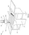
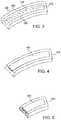
- FIG. 3shows a perspective view of a 3-D printed tooling shell
- FIG. 4shows a perspective view of 3-D printed tooling shell with CFRP inserted therein.
- FIG. 5is a cross sectional perspective view of the combined material and tooling shell.
- FIG. 6shows a side view of an exemplary interior door panel 610 in a transport structure using the dual assembled component.
- FIG. 7is a flow diagram illustrating an exemplary process for producing a component having a composite reinforcement overlaying a tooling shell to form an integrated structure for use as a component in a transport structure.
- FIG. 8is an illustration of an integrated structure composed of an overlay of fabric composite reinforcement over additively manufactured tooling.
- FIG. 9is an illustration of an integrated structure including tooling formed with an internal lattice structure.
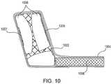
- FIG. 10is an illustration of the integrated structure having pockets and tooling with topology optimization.
- FIG. 11is an illustration of an integrated structure using co-molded nodes.
- FIG. 12is a flow diagram illustrating an exemplary process for producing a component having a composite material over a tooling shell to produce an integrated structure for use as a component in a transport structure.
- FIG. 13is an illustration of an integrated structure including composite material sandwiched between nodes and fastened via a mechanical clamp.
- FIGS. 14A-Billustrate examples of an integrated structure using a composite skin and multi-material tools.
- FIG. 15is an example of an integrated structure using peel plies on the cured composite surface.
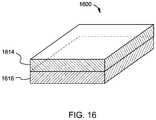
- FIG. 16is an illustration of an AM hybrid composite structure.
- FIG. 17illustrate an AM hybrid composite structure with one or more guidelines.
- FIG. 18Aillustrate a top view of an AM hybrid composite structure with one or more guidelines.
- FIG. 18Billustrate a side view of the AM hybrid composite structure with the one or more guidelines in FIG. 18A .
- FIGS. 19A-Billustrate an AM hybrid composite structure with one or more vacuum channels.
- FIGS. 20A-Billustrate an AM hybrid composite structure with one or more resin channels.
- FIG. 21illustrates a method of manufacturing a hybrid composite structure.
- an AM hybrid composite structureincludes a first portion and a second portion.
- the first portionincludes a first material.
- the second portionincludes a second material.
- the second portionis configured to integrate with the first portion.
- the second portionfurther includes one or more AM elements that are configured to enable integration of the second portion with the first portion to form an integrated component including both the second portion and the first portion.
- a method of manufacturing a hybrid composite structureincludes manufacturing a first portion, and additively manufacturing a second portion.
- the step of additively manufacturing the second portionincludes co-printing one or more additively manufactured (AM) elements.
- the methodfurther includes using the one or more AM elements as a part of a tool to integrate the first portion with the second portion, and forming an integrated component including both the first portion and the second portion.
- AMadditively manufactured
- 3-D printing of internal core structuresenables the tooling function to be facilitated by the 3-D printed core structures, thereby eliminating the need for some external tools. Additional functions that can be included in the 3-D printed core structures are described below.
- 3-D printingadditive manufacturing
- 3-D printing techniquesprovide manufacturers with the flexibility to design and build parts having intricate internal lattice structures and/or profiles that are not possible to manufacture via traditional manufacturing processes.
- FIG. 1is a flow diagram 100 illustrating an exemplary process of initiating a process of 3-D printing.
- a data model of the desired 3-D object to be printedis rendered (step 110 ).
- a data modelis a virtual design of the 3-D object.
- the data modelmay reflect the geometrical and structural features of the 3-D object, as well as its material composition.
- the data modelmay be created using a variety of methods, including 3D scanning, 3D modeling software, photogrammetry software, and camera imaging.
- 3D scanning methods for creating the data modelmay also use a variety of techniques for generating a 3-D model. These techniques may include, for example, time-of flight, volumetric scanning, structured light, modulated light, laser scanning, triangulation, and the like.
- 3-D modeling softwaremay include one of numerous commercially available 3-D modeling software applications.
- Data modelsmay be rendered using a suitable computer-aided design (CAD) package, for example in an STL format.
- STL filesare one example of a file format associated with commercially available CAD software.
- a CAD programmay be used to create the data model of the 3-D object as an STL file. Thereupon, the STL file may undergo a process whereby errors in the file are identified and resolved.
- the data modelcan be “sliced” by a software application known as a slicer to thereby produce a set of instructions for 3-D printing the object, with the instructions being compatible and associated with the particular 3-D printing technology to be utilized (step 120 ).
- a slicera software application known as a slicer to thereby produce a set of instructions for 3-D printing the object, with the instructions being compatible and associated with the particular 3-D printing technology to be utilized (step 120 ).
- Numerous slicer programsare commercially available. Slicer programs convert the data model into a series of individual layers representing thin slices (e.g., 100 microns thick) of the object be printed, along with a file containing the printer-specific instructions for 3-D printing these successive individual layers to produce an actual 3-D printed representation of the data model.
- a common type of file used for this purposeis a G-code file, which is a numerical control programming language that includes instructions for 3-D printing the object.
- the G-code file, or other file constituting the instructionsis uploaded to the 3-D printer (step 130 ). Because the file containing these instructions is typically configured to be operable with a specific 3-D printing process, it will be appreciated that many formats of the instruction file are possible depending on the 3-D printing technology used.
- the appropriate physical materials necessary for use by the 3-D printer in rendering the objectare loaded into the 3-D printer using any of several conventional and often printer-specific methods (step 140 ).
- FDMfused deposition modelling
- materialsare often loaded as filaments on spools, which are placed on one or more spool holders.
- the filamentsare typically fed into an extruder apparatus which, in operation, heats the filament into a melted form before ejecting the material onto a build plate or other substrate, as further explained below.
- SLSselective laser sintering
- the materialsmay be loaded as powders into chambers that feed the powder to a build platform.
- other techniques for loading printing materialsmay be used.
- the respective data slices of the 3-D objectare then printed based on the provided instructions using the material(s) (step 150 ).
- a laserscans a powder bed and melts or sinters the powder together where structure is desired, and avoids scanning areas where the sliced data indicates that nothing is to be printed. This process may be repeated thousands of times until the desired structure is formed, after which the printed part is removed from a fabricator.
- fused deposition modellingparts are printed by applying successive layers of model and support materials to a substrate.
- any suitable 3-D printing technologymay be employed for purposes of this disclosure.
- FIG. 2is a block diagram of an exemplary 3-D printer 200 . While any number of 3-D printed technologies can be suitably employed, the 3-D printer 200 of FIG. 2 is discussed in the context of an FDM technique.
- 3-D printer 200includes an FDM head 210 that in turn includes extrusion nozzles 250 A and 250 B, a moveable build stage 220 , and a build plate 230 at the top of the build stage 220 .
- a plurality of materialsmay be used for printing an object.
- One or more suitable filament materials 260may be wound on a spool (not shown) and fed into FDM head 210 .
- the materialmay be provided as a powder or in other forms).
- the FDM head 210can be moved in X-Y directions based on the received printing instructions by a numerically controlled mechanism such as a stepper motor or servomotor.
- the materialwhich may in one exemplary embodiment constitute a thermoplastic polymer, may be fed to the FDM head 210 which includes the extrusion nozzles 250 A and 250 B.
- the extruder in FDM head 210heats the filament material 260 into a molten form, and extrusion nozzle 250 A ejects the molten material and deposits it onto the build plate 230 of build stage 220 .
- the FDM head 210moves about a horizontal (X-Y) plane such that extrusion nozzle 250 A drops the filament material 260 at the target location to form a line 240 of applied material.
- the FDM head 210may also be configured to move in the Z-direction and/or to rotate about one or more axes in certain configurations).
- the layer 270 of filament material 260is formed by depositing the filament material 260 line by line, with each line of the filament material 260 hardening as the material is deposited on the build plate 230 . After one layer 270 is formed at the appropriate locations in the X-Y plane, the next layer may be formed in a similar way.
- the build plate 230may be a component of a controlled table moveable in at least the vertical Z direction.
- the build stage 220 and build plate 230may be lowered by an amount proportional to the thickness of layer 270 in the vertical (Z) direction.
- the build stage 220 and build plate 230may be lowered so that the printer can begin application of the next layer. Rendering and completing a layer and lowering the build stage 220 and build plate 230 may be repeated until a plurality of cross sectional layers (e.g., from lines 240 ) having a desired shape and composition are created.
- a plurality of different materialsmay be used to print the object.
- two different filament materials 260 and 280may concurrently be applied by respective extruder nozzles 250 A and 250 B.
- a part for a transport structureis formed using an appropriately shaped and structured tooling shell to mold one or more layers of composite material.
- the composite materialis adhered to the surface of the tooling shell to form an integrated structure that includes both the composite material and the tooling shell.
- the integrated structureis operable for use as a component in a transport structure such as a vehicle.
- the tooling shellis 3-D printed, thereby eliminating the often costly and time-consuming techniques associated with the laborious machining process.
- the tooling shellmay play the dual role of molding the composite material and serving as a useful structure in conjunction with the molded material to form a component for assembly within the transport structure itself, such as a vehicle panel, joint or other component, an aircraft wing, and the like.
- FIG. 3shows a perspective view of a 3-D printed tooling shell 300 .
- the tooling shellmay include any material having appropriate or suitable characteristics for molding another material.
- CFRPcarbon fiber reinforced polymer
- an Invar alloymay be a suitable candidate for use in molding the material because its coefficient of thermal expansion is very similar to that of carbon fiber.
- the tooling structuremay be composed of other materials, including metals, alloys, and plastics.
- the indentation 302 in the 3-D printed tooling shell 300may be of a suitable volume for accommodating an appropriate amount of material to be molded.
- an upper half of a tooling shellmay be provided in order to seal the material during curing.
- vacuum and fluid channelsmay be integrated into the 3-D printed tooling shell 300 in order to enable resin material to be provided to indentation 302 to facilitate the process of fabricating the material.
- the 3-D printed tooling shell 300may ultimately serve as a structural part in addition to a mold, the choice of materials out of which the 3-D printed tooling shell 300 can be made may also be limited by the types of materials that are appropriate for the final component as assembled into the transport structure.
- the adhesive to be used for CRFP and the metal 3-D printed moldcan be the matrix material of the CFRP itself.
- small surface indentations 304that had been 3-D printed into the material. Because the 3-D printed tooling shell 300 and the material to be molded can ultimately form a single component for assembly into a transport structure, it may be desirable in some embodiments to provide a mechanism to cause the component to adhere to the interior 302 of the 3-D printed tooling shell 300 .
- the purpose of the small surface indentations 304are to assist in providing surface adhesion between the inner portion of the 3-D printed tooling shell 300 and the material to be molded in the 3-D printed tooling shell 300 .
- surface indentationsmay also be formed on the inner sidewalls 306 of the tooling shell to further facilitate the surface adhesion process.
- a resinmay be applied to inner surface 302 and/or the inner sidewalls 306 prior to insertion of the materials to be molded.
- clamps, screws, nuts and bolts, nails, thermal fusion, etc.may be used to secure the composite material to the tooling shell.
- FIG. 4shows a perspective view of 3-D printed tooling shell 400 with CFRP inserted therein.
- a geometry 404 of a structure to be molded within the 3-D printed tooling shell 400may be designed to conform to the shape of an inner surface of the 3-D printed tooling shell 400 , depending on how the mold is configured. In this manner, the tooling shell acts as a section of a mold to shape the composite material that will be cured into the a portion of the component, as described further below.
- a composite fabrication process including a composite layupmay be performed using the 3-D printed tooling shell 400 .
- carbon fiber material(or another suitable material) may be applied via a layup process on inner surface of the 3-D printed tooling shell 400 as a first step in producing the component.
- the carbon fiber materialmay be laid over the 3-D printed tooling shell 400 , compressed and cured.
- FIG. 5is a cross sectional perspective view 500 of the combined material 502 and tooling shell 504 .
- the difference in shading between material 502 and tooling shell 504shows that the two structures in this particular embodiment have a different material composition, although such a feature need not be necessary in certain embodiments.
- FIG. 6shows a side view of an exemplary interior door panel 610 in a transport structure using the dual assembled component 600 .
- the door panelincludes a first component 606 and a second component 608 , either of which may be molded or 3-D printed.
- first component 606is adhered via any available means to a surface 607 of the dual assembled component 600 described in FIGS. 3-5 .
- Second component 608is adhered via any available means to a surface 609 of the component of FIG. 4 (i.e., the unseen bottom portion of the component in FIG. 4 ).
- the interior door panel 610can thereupon be used in a transport structure with the carbon fiber material 604 appropriately placed. It should be understood that the integration of the component with an interior door panel is purely for illustrative purposes, and the component of FIG. 4 can be used in a wide number of practical applications in various portions of a transport structure.
- a layupuses pre-impregnated (“prepreg”) carbon fiber plies that are delivered onto the 3-D printed tooling shell 400 ( FIG. 4 ) with the resin matrix applied.
- prepregpre-impregnated
- the prepreg techniqueprovides effective resin penetration and assists in ensuring substantially uniform dispersion of the resin.
- the prepreg pliesmay be applied onto the 3-D printed tooling shell 400 to form a laminate stack.
- a dry lay-upuses dry woven fiber sheets. Resin may thereupon be applied to the dry plies after layup is complete, such as by resin infusion. In an alternative exemplary embodiment, wet layup may be used wherein each ply may be coated with resin and compacted after being placed.
- a top shell or a seal for the moldmay be 3-D printed and applied over 3-D printed tooling shell 400 to provide a means to mold the structure of the material 502 ( FIG. 5 ), for example, into the geometry 404 of the inner part of the 3-D printed tooling shell 400 ( FIG. 4 ).
- the carbon fiber materialmay, for example, be vacuum compacted and baked in an oven for a designated time period.
- the 3-D-printed tooling shellmay be used in connection with a variety of composite manufacturing techniques including, for example, Resin Transfer Molding (RTM), hand layup, prepregs, sheet molding, and Vacuum Assisted Resin Transfer Molding (VARTM).
- RTMResin Transfer Molding
- VARTMVacuum Assisted Resin Transfer Molding
- FIG. 7shows an exemplary flow diagram of a method for creating a component for use in a transport structure.
- a tooling shellis 3-D printed using a geometry that can ultimately enable it to be used as part of an integrated structure for further within another structure such as a vehicle panel.
- the tooling shellmay be designed for potential adherence to a material to be subsequently used.
- the materialsuch as CFRP or another composite fabric, is applied and a composite fabrication process is used to mold and harden the material.
- the materialadheres to the tooling shell and a resulting component is formed which includes an integrated structure composed of the cured material and the tooling shell.
- the integrated structureis assembled as a component into a transport structure.
- a 3-D printed plastic frameis first used as a template for composite tooling. On completion of the cure of the composite material, the resulting assembly may then be used as a frame or other component for a transport structure.
- FIG. 8is an illustration of a structure composed of an overlay of fabric composite reinforcement over additively manufactured tooling.
- the 3-D printing technology selectionmay be driven by the materials requirement and by the speed of the printing process.
- a 3-D printed plastic frame 802is formed.
- plastic printing processesare typically 25-50 times faster than metal printing processes.
- a further benefit in using additively manufactured plastic toolingis the ability to obtain larger parts because the build chambers of plastic 3-D printers are typically much larger than those of metal 3-D printers.
- the plastic 3-D printerscan, in many cases, print much smoother surfaces.
- the material usedis Acrylonitrile Butadiene Styrene (ABS), a common thermoplastic polymer.
- ABSAcrylonitrile Butadiene Styrene
- any number of suitable materialsmay be used depending on the application and the properties of the materials needed.
- a CNC foam core 806is additively manufactured and coupled to the 3-D printed plastic frame 802 using an adhesive or other available means.
- the 3-D printed plastic frame 802 and cnc foam core 806are co-printed in a single rendering.
- the foam coremay be composed of the same material as the 3-D printed plastic frame 802 .
- a honeycomb panel configurationis used in place of foam core. It will be appreciated that the illustrated embodiment in FIG. 8 is exemplary in nature as a number of materials and shapes may alternatively be used for purposes of this disclosure.
- a variety of fiber composite fabricsmay be used in the subsequent composite fabrication process, depending on strength requirements and other factors.
- Some examples of possible materialsinclude glass fiber, carbon fiber, Kevlar, and the like.
- glass fiber prepreg layer 804are draped over the additively manufactured tooling.
- the glass fiber prepreg layer 804may include, in one exemplary embodiment, a fiber reinforced polymer (FRP) skin (E Glass).
- FRPfiber reinforced polymer
- Other composites, including carbon fibermay be used as well. Layup is performed on the FRP.
- the integrated structurecomposed of the ABS tooling with the 3-D printed plastic frame 802 and cnc foam core 806 and the overlaid glass fiber composite (e.g., glass fiber prepreg layer 804 ) may then be used as a component in a transport structure.
- the overlaid glass fiber compositee.g., glass fiber prepreg layer 804
- the 3-D printed toolingmay include a structure that uses an optimized topology.
- FIG. 9shows an illustration of an integrated structure including tooling formed with an internal lattice structure.
- Plastic tooling 902includes a lattice structure designed for the loads to which it will be subject when it is assembled as a component.
- the foam core or honeycomb panel structure 906is included, with the layers of glass fiber reinforced polymer 904 overlaid on the tooling structure.
- One advantage of this structureincludes the savings in plastic material achieved via use of the lattice.
- the toolingmay be additively manufactured with pockets for a flush finish.
- FIG. 10is an illustration with the integrated structure having pockets and tooling with topology optimization.
- tooling component 1002is 3-D printed with pockets 1007 , 1009 and hollow sections 1008 .
- the pocket 1007enables the end areas of the glass fiber material surrounding the tooling to have a flush finish.
- the structurefurther includes a component 1006 with a honeycomb or foam filling.
- CFRP or another composite materialmay be used to provide local reinforcement for the pockets.
- prepreg layers of GFRP(or another suitable composite) may be overlaid and cured over the tooling to produce the integrated structure.
- FIG. 11is an illustration of an integrated structure using co-molded nodes.
- tooling shell 1102is additively manufactured using ABS or another suitable material.
- FRP or another suitable, e.g., composite material 1104is inlaid and cured over the tooling shell.
- a 3-D printed inner node 1114is co-printed with the tooling or printed separately and added to secure a first side of portions 1120 of the composite material 1104 .
- a 3-D printed outer node 1112is inserted over a second side of portions 1120 of the composite material.
- the composite materialis therefore clamped and secured to the tooling shell, and the entire integrated structure may be used as a component in a transport structure.
- the nodesare co-printed using aluminum to ensure strength. Other materials, however, may be equally suitable.
- AM metal nodescan be implemented as suspension pick-up points or interfaces for the crush rails associated with the overall transport structure.
- Crush railsare energy absorbing rail structures that may be implemented on a vehicle to enable the vehicle to absorb energy from an impact in a controlled and directed manner.
- the railsmay be sandwiched between the metal nodes, which in turn may be attached to the vehicle suspension. An example of such an arrangement is shown in FIG. 13 .
- mechanical clampingcan be used in connection with vacuum connectors to cure a composite layup.
- FIG. 13is an illustration of an integrated structure 1300 including composite material sandwiched between nodes and fastened via a mechanical clamp.
- the integrated structure 1300includes upper and lower aluminum nodes 1302 a - b , which may be additively manufactured.
- Beneath node 1302 bis tooling shell 1308 , which may be additively manufactured using FDM or another suitable technology.
- tooling shell 1308is composed of ABS or a thermoplastic such as ULTEM (polyetherimide).
- Laid over tooling shell 1308are two composite skin layers 1306 a and 1306 b that may be composed of GFRP. Near their end, GFRP layers 1306 a and 1306 b contact with nodes 1302 a - b . GFRP layers 1306 a and 1306 b may be cured on top of both of the Al node 1302 b and the FDM tooling shell 1308 . GFRP layers 1306 a - b may then be clamped by nodes 1302 a , which may be placed on top of GFRP layers 1306 a and 1306 b.
- a feature 1304 for mechanical fasteningmay be employed.
- the feature 1304 in this embodimentis a large opening in which a bolt or other fastener can be inserted.
- the fastenercan provide a force to secure the layers 1306 a and 1306 b , such as by using a standard threaded bolt, a nut-bolt combination or any other suitable mechanical fastening or clamping mechanism.
- the clamping featuremay be different from the aperture 1304 and may include other types of fasteners or openings to accommodate fasteners.
- a protrusion 1310 from the node 1302 bincludes an aperture that is configured to “snap fit” into another protrusion 1312 , which may be a protrusion from the FDM tooling shell 1308 .
- the protrusion 1312is a gradual protrusion jutting out of a longer FDM member (hidden from view by node 1320 b ) arranged in the vertical direction, with the larger protrusion 1312 at the end.
- the Al node 1302 bmay contact and press against the longer FDM member. As the Al node 1302 b is moved downward relative to the longer FDM member, the pressure or force causes the larger FDM protrusion 1312 to snap into place.
- protrusion 1312may be affixed to a vehicle suspension system, thereby fastening the integrated structure 1300 to the suspension system.
- FIG. 12is a flow diagram illustrating an exemplary process for producing a component having a composite material over a tooling shell to produce an integrated structure for use as a component in a transport structure.
- a plastic tooling shellsuch as an ABS shell is additively manufactured using a suitable 3-D printer, such as an FDM 3-D printer.
- a foam core or honeycomb panelis 3-D printed, and aluminum nodes are also 3-D printed.
- two or more of the structuresare co-printed. It should be noted that different materials may be used than the materials identified, depending on the embodiment and objectives.
- the tooling shellis coupled to or adjoined with the foam core.
- this stepmay be unnecessary.
- an appropriate adhesive, screw, clamp, or other connection meansmay be used.
- the appropriate materialsuch as GFRP
- the tooling shell and foam corehave an adhesive means to adhere to the composite. In other embodiments, other adherence mechanisms may be used.
- the aluminum nodes printed at 1204may be used to clamp the composite material to the tooling shell in a manner described above with respect to FIG. 11 .
- the resulting integrated structuremay be used as a component in a transport structure.
- the structuremay use a lattice or other mechanical arrangement, such as a CFRP layer, to provide additional support depending on the stresses to which the structure may be subject.
- the tooling shellcan be optimized and printed with pockets for placing additional reinforcement where needed.
- GFRPis overlaid with the tooling structure, but CFRP is used in pockets on the tooling shell to optimize load path for load transfer.
- unidirectional reinforcementhas fibers in one direction while woven reinforcement may have fibers running at 0-degree and 90-degree angles, or other angles between 0-degrees and 90-degrees.
- load transferis the change of load sustained by the different wheels during the processes of longitudinal and lateral acceleration, which includes braking and deceleration.
- Other types of loadsmay also be involved in transport structures and mechanized assemblies.
- a shear loadis a force that causes shear stress when applied to a structural element. Reinforcement using composite fiber materials, lattices, and other structures may be necessary in cases where load the transfer mechanics of a part, including the expected shear loads, dictates it.
- multi-material toolsmay be used.
- certain sections of the toolingmay be printed with a dissolvable material. Once the composite is overlaid and cured, these sections may be dissolved. This technique may be ideal for weight saving mechanisms and in designs where only the composite shell is needed. In the case where only composite skin is needed in a certain section, multi-material tools may be used.
- release mechanismsrelease agents, tooling surface preparation, etc. may be used to enable certain sections of the tooling to come out or become available after the composite has cured to achieve sections with just composite skin.
- FIGS. 14A-Bare examples of an integrated structures 1400 using a composite skin and multi-material tools.
- a multi-material tooling shell including components 1404 and 1406may be additively manufactured.
- component 1406may constitute a known dissolvable material.
- a skin or material 1402such as GFRP or CFRP is laid up over the tooling shell as discussed above. It is desired that the final integrated structure include components 1404 and 1402 .
- component 1406is used merely for molding purposes to shape and stabilize material 1402 and to allow it to cure.
- component 1406may be dissolved away using techniques conventionally known to produce the final integrated structure 1400 in FIG. 14B . Using these multi-material techniques in conjunction with the methods disclosed herein, an increasingly wide variety of structures may be produced.
- FIG. 15is an example of an integrated structure 1500 including a composite 1514 such as GFRP, CFRP, or the like.
- an additively manufactured tool 1516is used to mold the composite 1514 during a layup process as well as to be a part of the structure being built.
- a layer of a material with chemically suitable propertiessuch as peel ply 1512
- another layer of peel ply 1512may be inserted over the composite 1514 .
- Bagging film 1508may include thru-bag vacuum connector for creating negative pressure.
- Sealant 1502may be used to seal the bagging film 1508
- a flash tape 1504may be used to secure the peel ply 1512 to the composite 1514 .
- the nature of the peel ply 1512enables the cured composite 1514 to be removed from the tool 1516 .
- the peel ply 1512may leave a certain texture on the surface of the cured composite 1514 that is conducive to adhesive bonding. After discarding the peel ply 1512 , adhesive can be applied between the tool-composite interface to form a strong bond between the tool 1516 and composite 1514 .
- FIG. 16is an illustration of an AM hybrid composite structure 1600 .
- the AM hybrid composite structure 1600includes a first portion 1614 , and a second portion 1616 .
- the first portion 1614includes a first material.
- the first portion 1614may include a composite layup.
- the first materialmay be a composite including carbon fiber and resin.
- the second portion 1616includes a second material.
- the second portion 1616may include an AM tool.
- the AM toolmay include a tooling shell (e.g., an AM tooling shell) and an AM internal core.
- the second portion 1616is configured to integrate with the first portion 1614 .
- the second portion 161further comprising one or more AM elements (not shown) configured to enable integration of the second portion 1616 with the first portion 1614 to form an integrated component, which is the AM hybrid composite structure 1600 , including both the second portion and the first portion.
- the integrated componentmay be further configured for assembly into a transport structure.
- the one or more AM elementsare configured to facilitate the integration of the first portion 1614 , and the second portion 1616 of the AM hybrid composite structure 1600 .
- the AM tool 1616enables the tooling function to be facilitated by the one or more AM elements, which are co-printed with the AM tool.
- the one or more AM elementsmay be co-printed the AM tooling shell.
- the one or more AM elementsmay be co-printed the AM internal core.
- the one or more AM elementsare further configured to eliminate the need for an external tool, which is a dedicated tool required in traditional manufacturing process. In this way, the manufacturing cost and time can be significantly reduced.
- FIG. 17illustrates an AM tool 1716 with one or more guidelines 1772 , 1774 .
- Traditional ply placement and orientationare achieved by using external tools.
- ply booksare used traditionally to guide ply placement and orientation.
- Ply booksare 2D drawings that document the layup process typically on a ply-by-ply basis.
- a laser projection systemmay be used as a tool to guide the process of ply placement and orientation.
- a laser proj ection systemcan be very expensive, and ply books can be very time-consuming.
- the AM tool 1716 with the one or more guidelines 1772 , 1774can guide ply placement and orientation and eliminate the need for external tools such as the laser projection system or the ply books.
- one or more guidelines 1772 , 1774 to assist in ply placementmay be 3-D printed into a surface of the AM tool 1716 to serve as guidance during the composite lamination phase of fabrication.
- FIG. 18Aillustrates a top view of an AM hybrid composite structure 1800 with one or more guidelines (e.g., 1872 a - d , 1874 a - b , 1876 a - b ).
- FIG. 18Billustrates a side view of the AM hybrid composite structure 1800 with the one or more guidelines (e.g., 1872 a - d , 1874 a - b , 1876 a - b ).
- the AM hybrid composite structure 1800may include a first portion 1814 and a second portion 1816 .
- the first portion 1814may include a composite layup, which may include one or more composite plies.
- the second portion 1816may include an AM tool 1816 .
- the AM tool 1816may include one or more AM elements, which may include the one or more guidelines 1872 a - d , 1874 , 1876 a - b , as shown in FIGS. 18A-B .
- the one or more guidelinese.g., 1872 a - d , 1874 a - b , 1876 a - b
- the one or more guidelinesmay be co-printed with the AM tool 1816 .
- the one or more guidelinescan enable accurate placement of the first portion 1814 (e.g., a carbon fiber composite) over the second portion 1816 (e.g., the AM tool).
- the one or more guidelinee.g., 1872 a - d , 1874 a - b , 1876 a - b
- the AM tool 1816is further configured to be a placement tool.
- the one or more guideline(e.g., 1872 a - d , 1874 a - b , 1876 a - b ) are configured to be a part of the placement tool, thus eliminating an external placement tool.
- the one or more guideline(e.g., 1872 a - d , 1874 a - b , 1876 a - b ) may be placed on a surface that is viewable by a technician/robot placing the one or more composite plies 1814 .
- the one or more guideline(e.g., 1872 a - d , 1874 a - b , 1876 a - b ) are configured to assist placement of the one or more composite plies.
- the one or more composite plies of the first portion 1814may be pre-stacked.
- the one or more guidelines(e.g., 1872 a - d , 1874 a - b , 1876 a - b ) may include one or more sets of guidelines configured to provide instructions and boundaries for trimming operation of the one or more composite plies.
- Each layer of the one or more composite pliesmay get guidelines from a peripheral of the layer, such as position, orientation, edge marking, etc.
- the guidelines 1872 a , 1872 b , 1872 c , and 1872 dmay provide orientation and placement of the one or more composite plies.
- the one or more guidelinesmay include one or more text or numerical instructions 1874 a , 1874 b .
- the guideline 1874 acan provide a coordinate system to guide the movement of the one or more composite plies.
- the one or more guidelinesmay include one or more edge markings 1876 a , 1876 b .
- the composite layup 1814may only cover a portion of a cross section of the AM tool 1816 .
- the guidelinesmay help to place and orientate the composite layup 1814 .
- the composite layup 1814may only cover an entire cross section of the AM tool, and the guidelines may help to place and orientate the composite layup.
- the one or more guidelinesmay provide information for stack-up of the one or more composite plies. Since the one or more guidelines (e.g., 1872 d , 1876 b ) are external to the composite layup 1814 , they may have information about the orientation of the one or more composite plies, fabric/weave, material, edge markings, and other numerical and text information pertinent to each ply of the composite layup 1814 .
- FIGS. 19A-Billustrate an AM hybrid composite structure 1900 with one or more vacuum channels 1982 .
- the AM hybrid composite structure 1900may include a first portion 1914 and a second portion 1916 .
- the first portion 1914may include a composite layup, which may include one or more composite plies.
- the second portion 1916may include an AM tool.
- the AM tool 1916may include a tooling shell 1916 a and an internal core 1916 b .
- the AM tool 1916may include one or more AM elements, which may include the one or more vacuum channels 1982 and vacuum ports 1984 , as shown in FIGS. 19A-B .
- the one or more vacuum channels 1982 and vacuum ports 1984may be co-printed with the AM tool 1916 .
- vacuum channels 1982may be incorporated into the integral composite structure 1900 such that no external vacuum devices to the vacuum bag 1908 are needed.
- the application of vacuum bagging over the laminateis usually used to consolidate the composite material and remove trapped gas.
- Traditional methodsrequire external vacuum generation devices to be attached to the external side of the vacuum bag.
- the attachment of the external vacuum generation devices to the external side of the vacuum bagmay increase the cost of the manufacturing process.
- Extra timemay be needed to attach the external vacuum device to the vacuum bag.
- the one or more vacuum channels 1982may be a part of a vacuum tool and eliminate an external vacuum device attached to the vacuum bag 1908 . It is advantageous to co-print the one or more vacuum channels 1982 with the AM tool 1916 to eliminate the external vacuum generation devices, thereby reducing the cost and time of the manufacturing process.
- FIG. 19Bis an example of the AM hybrid composite structure 1900 including the composite layup 1914 .
- the composite layup 1914may include GFRP, CFRP, or the like.
- the additively manufactured tool 1916may be is used to mold the composite 1914 during a layup process as well as to be a part of the integral hybrid composite structure 1900 being built.
- a layer of a material with chemically suitable propertiessuch as peel ply 1912 , can be arranged between the AM tool 1916 and the composite 1914 .
- another layer of peel ply 1912may be inserted over the composite 1914 .
- the vacuum bag 1908may not include a thru-bag vacuum connector.
- the co-printed one or more vacuum channels 1982eliminate the external vacuum generation devices being attached to the external side of the vacuum bag 1908 .
- the one or more vacuum channels 1982may be a part of the internal core 1916 b and extend out of the tooling shell 1916 a .
- the one or more ports 1984may be disposed on an exterior surface of the AM tool 1916 .
- the one or more ports 1984may be disposed on an exterior surface of the tooling shell 1916 b .
- the one or more vacuum channels 1982may extend inward from a respective one or more ports 1984 on the exterior surface of the AM tool 1916 .
- the one or more ports 1984may be configured to enable a negative pressure to be applied via an associated one or more vacuum channels 1982 to the first portion 1914 .
- FIGS. 20A-Billustrate an AM hybrid composite structure 2000 with one or more resin channels 2086 and one or more resin ports 2088 .
- the AM hybrid composite structure 2000may include a first portion 2014 and a second portion 2016 .
- the first portion 2014may include a composite layup, which may include one or more composite plies.
- the second portion 2016may include an AM tool.
- the AM tool 2016may include a tooling shell 2016 a and an internal core 2016 b .
- the AM tool 2016may include one or more AM elements, which may include the one or more resin channels 2086 and resin ports 2088 , as shown in FIGS. 20A-B .
- the one or more resin channels 2086 and resin ports 2088may be co-printed with the AM tool 2016 .
- resin channels 2086may be incorporated into the integral composite structure 2000 such that no external resin devices to the vacuum bag 2008 are needed.
- One method for manufacturing composite structuresis to infuse resin into the composite layup, such as dry fiber.
- resin in infused into the fiberusing external resin feed lines that also feed into the vacuum bag.
- resin infusion channelscan be incorporated into the 3-D printed core structures such that hardware external to the vacuum bag surface is not necessary.
- the attachment of the external hardware to the external side of the vacuum bagmay increase the cost and time of the manufacturing process.
- the one or more resin channels 2086may be a part of a resin tool and eliminate external hardware attached to the vacuum bag 2008 . It is advantageous to co-print the one or more resin channels 2086 with the AM tool 2016 to eliminate the external hardware, thereby reducing the cost and time of the manufacturing process.
- FIG. 20Bis an example of the AM hybrid composite structure 2000 including the composite layup 2014 .
- a layer of a material with chemically suitable propertiessuch as peel ply 2012
- another layer of peel ply 2012may be inserted over the composite 2014 .
- Between the upper peel ply layer 2012 and the vacuum bag 2008may be a breather 2010 .
- the co-printed one or more resin channels 2086eliminate the external hardware being attached to the external side of the vacuum bag 2008 .
- the one or more resin channels 2086may be a part of the internal core 2016 b and extend out of the tooling shell 2016 a .
- the one or more resin ports 2088may be disposed on an exterior surface of the AM tool 2016 .
- the one or more resin ports 2088may be disposed on an exterior surface of the tooling shell 2016 a .
- the one or more resin channels 2086may extend inward from a respective one or more resin ports 2088 on the exterior surface of the AM tool 2016 .
- the one or more resin channels 2086may be a part of a resin infusion tool.
- the one or more resin ports 2088may be configured to enable resin to be infused via an associated one or more resin channels 2086 to the first portion 2014 .
- an AM hybrid composite structuremay include a first portion and a second portion.
- the first portionmay include a composite layup, which may include one or more composite plies.
- the second portionmay include an AM tool.
- the AM toolmay include a tooling shell and an internal core.
- the AM toolmay include one or more AM elements.
- the one or more AM elementsmay include one or more ports and one or more channels.
- a first set of the one or more portsmay be configured to enable a negative pressure to be applied to the first portion via an associated one or more channels.
- a second set of the one or more portsis configured to enable resin to be infused into the first portion via an associated one or more channels.
- a method of manufacturing a hybrid composite structure 2100is disclosed, as shown in FIG. 21 .
- the method 2100includes a step 2102 of manufacturing a first portion.
- the method 2100includes a step 2104 of additively manufacturing a second portion.
- the step 2104includes co-printing one or more additively manufactured (AM) elements, as illustrated at 2106 .
- the method 2100includes a step 2108 of using the one or more AM elements as a part of a tool to integrate the first portion with the second portion.
- the method 2100further includes a step 2110 of forming an integrated component including both the first portion and the second portion.
- the one or more AM elementsmay comprise one or more guidelines, and wherein the first portion comprises one or more composite plies.
- using the one or more AM elements as a part of a toolcomprises using the one or more guidelines to assist placing the one or more composite plies.
- the method 2100may further include pre-stacking the one or more composite plies.
- the step 2108may include using the one or more guidelines to assist orientation of the one or more composite plies.
- the one or more AM elementsmay comprise one or more ports and one or more channels.
- the step 2108may comprise using the one or more AM elements to enable negative pressure to be applied to the first portion.
- the step 2108may comprise using the one or more AM elements to enable resin to be infused into the first portion.
- the second portioncomprises a tooling shell and an AM internal core.
- the step 2106may comprise co-printing one or more AM ports with the tooling shell.
- the step 2106may comprise the second portion comprises a tooling shell and an AM internal core, wherein co-printing one or more AM elements comprises co-printing one or more AM channels with the AM internal core.
- the step 2106may comprise co-printing one or more AM ports, a first portion of the one or more ports being configured to enable a negative pressure to be applied to the first portion, a second portion of the one or more ports being configured to enable resin to be infused into the first portion.
- the step 2106may comprise co-printing one or more AM channels, a first set of the one or more channels being configured to enable negative pressure to be applied to the first portion, a second set of the one or more channels being configured to enable resin to be infused into the first portion.
Landscapes
- Engineering & Computer Science (AREA)
- Chemical & Material Sciences (AREA)
- Mechanical Engineering (AREA)
- Materials Engineering (AREA)
- Composite Materials (AREA)
- Manufacturing & Machinery (AREA)
- Physics & Mathematics (AREA)
- Optics & Photonics (AREA)
- Structural Engineering (AREA)
- Ceramic Engineering (AREA)
- Civil Engineering (AREA)
- Architecture (AREA)
- Combustion & Propulsion (AREA)
- Transportation (AREA)
- Textile Engineering (AREA)
- Moulding By Coating Moulds (AREA)
Abstract
Description
Claims (36)
Priority Applications (4)
| Application Number | Priority Date | Filing Date | Title |
|---|---|---|---|
| US16/114,035US10836120B2 (en) | 2018-08-27 | 2018-08-27 | Hybrid composite structures with integrated 3-D printed elements |
| CN201980068697.7ACN112930253A (en) | 2018-08-27 | 2019-08-20 | Hybrid composite structure with integrated 3-D printing elements |
| EP19854480.1AEP3843967A4 (en) | 2018-08-27 | 2019-08-20 | HYBRID COMPOSITE STRUCTURES WITH INTEGRATED 3D PRINTED ELEMENTS |
| PCT/US2019/047286WO2020046649A1 (en) | 2018-08-27 | 2019-08-20 | Hybrid composite structures with integrated 3-d printed elements |
Applications Claiming Priority (1)
| Application Number | Priority Date | Filing Date | Title |
|---|---|---|---|
| US16/114,035US10836120B2 (en) | 2018-08-27 | 2018-08-27 | Hybrid composite structures with integrated 3-D printed elements |
Publications (2)
| Publication Number | Publication Date |
|---|---|
| US20200061935A1 US20200061935A1 (en) | 2020-02-27 |
| US10836120B2true US10836120B2 (en) | 2020-11-17 |
Family
ID=69586823
Family Applications (1)
| Application Number | Title | Priority Date | Filing Date |
|---|---|---|---|
| US16/114,035Active2039-02-14US10836120B2 (en) | 2018-08-27 | 2018-08-27 | Hybrid composite structures with integrated 3-D printed elements |
Country Status (4)
| Country | Link |
|---|---|
| US (1) | US10836120B2 (en) |
| EP (1) | EP3843967A4 (en) |
| CN (1) | CN112930253A (en) |
| WO (1) | WO2020046649A1 (en) |
Cited By (1)
| Publication number | Priority date | Publication date | Assignee | Title |
|---|---|---|---|---|
| US11247367B2 (en)* | 2017-02-10 | 2022-02-15 | Divergent Technologies, Inc. | 3D-printed tooling shells |
Families Citing this family (3)
| Publication number | Priority date | Publication date | Assignee | Title |
|---|---|---|---|---|
| DE102018207444A1 (en)* | 2018-05-15 | 2019-11-21 | Bayerische Motoren Werke Aktiengesellschaft | Process for producing a structural component |
| EP4171923A1 (en)* | 2020-06-24 | 2023-05-03 | General Electric Company | Method for manufacturing a composite structure and composite structure |
| DE102022205549A1 (en)* | 2022-05-31 | 2023-11-30 | Siemens Mobility GmbH | Additively manufactured cladding component with a hybrid structure |
Citations (304)
| Publication number | Priority date | Publication date | Assignee | Title |
|---|---|---|---|---|
| EP0373101A2 (en) | 1988-12-02 | 1990-06-13 | Otto Dipl.-Ing. Bay | Method and device for manufacturing, cutting and folding drawing sheets |
| US5203226A (en) | 1990-04-17 | 1993-04-20 | Toyoda Gosei Co., Ltd. | Steering wheel provided with luminous display device |
| WO1996036455A1 (en) | 1995-05-16 | 1996-11-21 | Edag Engineering + Design Ag | Device for feeding welding bolts to a welding gun |
| WO1996036525A1 (en) | 1995-05-19 | 1996-11-21 | Edag Engineering + Design Ag | Process for automatically fitting a motor vehicle body component |
| WO1996038260A1 (en) | 1995-05-30 | 1996-12-05 | Edag Engineering + Design Ag | Container changer |
| US5742385A (en) | 1996-07-16 | 1998-04-21 | The Boeing Company | Method of airplane interiors assembly using automated rotating laser technology |
| US5990444A (en) | 1995-10-30 | 1999-11-23 | Costin; Darryl J. | Laser method and system of scribing graphics |
| US6010155A (en) | 1996-12-31 | 2000-01-04 | Dana Corporation | Vehicle frame assembly and method for manufacturing same |
| US6096249A (en) | 1996-12-05 | 2000-08-01 | Teijin Limited | Method for molding fiber aggregate |
| US6140602A (en) | 1997-04-29 | 2000-10-31 | Technolines Llc | Marking of fabrics and other materials using a laser |
| US6252196B1 (en) | 1996-10-11 | 2001-06-26 | Technolines Llc | Laser method of scribing graphics |
| US6250533B1 (en) | 1999-02-18 | 2001-06-26 | Edag Engineering & Design Ag | Clamping device for use in motor vehicle production lines and production line having such a clamping device |
| US6318642B1 (en) | 1999-12-22 | 2001-11-20 | Visteon Global Tech., Inc | Nozzle assembly |
| US6365057B1 (en) | 1999-11-01 | 2002-04-02 | Bmc Industries, Inc. | Circuit manufacturing using etched tri-metal media |
| US6391251B1 (en) | 1999-07-07 | 2002-05-21 | Optomec Design Company | Forming structures from CAD solid models |
| US6409930B1 (en) | 1999-11-01 | 2002-06-25 | Bmc Industries, Inc. | Lamination of circuit sub-elements while assuring registration |
| US6468439B1 (en) | 1999-11-01 | 2002-10-22 | Bmc Industries, Inc. | Etching of metallic composite articles |
| WO2003024641A1 (en) | 2001-08-31 | 2003-03-27 | Edag Engineering + Design Aktiengesellschaft | Roller folding head and method for folding a flange |
| US6554345B2 (en) | 1997-10-23 | 2003-04-29 | Ssab Hardtech Ab | Lightweight beam |
| US6585151B1 (en) | 2000-05-23 | 2003-07-01 | The Regents Of The University Of Michigan | Method for producing microporous objects with fiber, wire or foil core and microporous cellular objects |
| US6644721B1 (en) | 2002-08-30 | 2003-11-11 | Ford Global Technologies, Llc | Vehicle bed assembly |
| US6811744B2 (en) | 1999-07-07 | 2004-11-02 | Optomec Design Company | Forming structures from CAD solid models |
| WO2004108343A1 (en) | 2003-06-05 | 2004-12-16 | Erwin Martin Heberer | Device for shielding coherent electromagnetic radiation and laser booth provided with such a device |
| US6866497B2 (en) | 2001-06-13 | 2005-03-15 | Kabushiki Kaisha Tokai Rika Denki Seisakusho | Molding apparatus having a projecting bulge located in a die half |
| US6919035B1 (en) | 2001-05-18 | 2005-07-19 | Ensci Inc. | Metal oxide coated polymer substrates |
| US6926970B2 (en) | 2001-11-02 | 2005-08-09 | The Boeing Company | Apparatus and method for forming weld joints having compressive residual stress patterns |
| WO2005093773A1 (en) | 2004-03-25 | 2005-10-06 | Audi Ag | System comprising an automotive fuse and an a/d converter |
| US20060108058A1 (en) | 2004-11-24 | 2006-05-25 | Chapman Michael R | Composite sections for aircraft fuselages and other structures, and methods and systems for manufacturing such sections |
| US20060108783A1 (en) | 2004-11-24 | 2006-05-25 | Chi-Mou Ni | Structural assembly for vehicles and method of making same |
| WO2007003375A1 (en) | 2005-06-30 | 2007-01-11 | Edag Engineering + Design Ag | Method and device for joining joining structures, particularly during the assembly of vehicle components |
| WO2007110236A1 (en) | 2006-03-28 | 2007-10-04 | Edag Gmbh & Co. Kgaa | Clamping device for holding and clamping components |
| WO2007110235A1 (en) | 2006-03-28 | 2007-10-04 | Edag Gmbh & Co. Kgaa | Clamping device for holding and clamping components |
| WO2007128586A2 (en) | 2006-05-10 | 2007-11-15 | Edag Gmbh & Co. Kgaa | Energy beam brazing or welding of components |
| WO2008019847A1 (en) | 2006-08-18 | 2008-02-21 | Fft Edag Produktionssysteme Gmbh & Co. Kg | Monitoring device for a laser machining device |
| US7344186B1 (en) | 2007-01-08 | 2008-03-18 | Ford Global Technologies, Llc | A-pillar structure for an automotive vehicle |
| WO2008068314A2 (en) | 2006-12-08 | 2008-06-12 | Edag Gmbh & Co. Kgaa | Flanging hand tool |
| WO2008087024A1 (en) | 2007-01-18 | 2008-07-24 | Toyota Motor Corporation | Composite of sheet metal parts |
| WO2008086994A1 (en) | 2007-01-15 | 2008-07-24 | Edag Gmbh & Co. Kgaa | Sheet-metal composite, method for joining sheets and joining device |
| WO2008107130A1 (en) | 2007-03-02 | 2008-09-12 | Edag Gmbh & Co. Kgaa | Automobile with facilitated passenger exit |
| WO2008138503A1 (en) | 2007-05-11 | 2008-11-20 | Edag Gmbh & Co. Kgaa | Crimping components in series production having short cycle times |
| WO2008145396A1 (en) | 2007-06-01 | 2008-12-04 | Edag Gmbh & Co. Kgaa | Edge curling tool |
| US7500373B2 (en) | 2004-09-24 | 2009-03-10 | Edag Gmbh & Co. Kgaa | Flanging device and flanging method with component protection |
| WO2009083609A2 (en) | 2008-01-03 | 2009-07-09 | Edag Gmbh & Co. Kgaa | Method for bending a workpiece |
| WO2009098285A1 (en) | 2008-02-07 | 2009-08-13 | Edag Gmbh & Co. Kgaa | Rotating table |
| WO2009112520A1 (en) | 2008-03-11 | 2009-09-17 | Edag Gmbh & Co. Kgaa | Tool, system and method for the manufacture of a cable harness |
| WO2009135938A1 (en) | 2008-05-09 | 2009-11-12 | Edag Gmbh & Co. Kgaa | Method and tool for producing a fixed connection to components joined in a form-fitted manner |
| WO2009140977A1 (en) | 2008-05-21 | 2009-11-26 | Edag Gmbh & Co. Kgaa | Clamping frame-less joining of components |
| US7637134B2 (en) | 2005-01-31 | 2009-12-29 | Edag Gmbh & Co. Kgaa | Flanging with a leading and following flanging die |
| US7710347B2 (en) | 2007-03-13 | 2010-05-04 | Raytheon Company | Methods and apparatus for high performance structures |
| US7716802B2 (en) | 2006-01-03 | 2010-05-18 | The Boeing Company | Method for machining using sacrificial supports |
| US7745293B2 (en) | 2004-06-14 | 2010-06-29 | Semiconductor Energy Laboratory Co., Ltd | Method for manufacturing a thin film transistor including forming impurity regions by diagonal doping |
| US7766123B2 (en) | 2006-03-29 | 2010-08-03 | Yamaha Hatsudoki Kabushiki Kaisha | Vehicle exhaust system |
| WO2010125058A1 (en) | 2009-04-27 | 2010-11-04 | Edag Gmbh & Co. Kgaa | Clamping device, system, and method for processing changing component types |
| WO2010125057A2 (en) | 2009-04-27 | 2010-11-04 | Edag Gmbh & Co. Kgaa | Robot support |
| US7852388B2 (en) | 2006-05-23 | 2010-12-14 | Panasonic Corporation | Imaging device |
| WO2010142703A2 (en) | 2009-06-09 | 2010-12-16 | Edag Gmbh & Co. Kgaa | Method and tool for edging a workpiece |
| US7908922B2 (en) | 2008-01-24 | 2011-03-22 | Delphi Technologies, Inc. | Silicon integrated angular rate sensor |
| WO2011032533A1 (en) | 2009-09-15 | 2011-03-24 | Edag Gmbh & Co. Kgaa | Vehicle body component composed of an exterior element and a fibre-reinforced plastic structural component connected to the rear side of said exterior element |
| US7951324B2 (en) | 2006-09-14 | 2011-05-31 | Ibiden Co., Ltd. | Method for manufacturing honeycomb structure |
| US8163077B2 (en) | 2005-09-28 | 2012-04-24 | Yissum Research Development Company Of The Hebrew University Of Jerusalem | Ink providing etch-like effect for printing on ceramic surfaces |
| US20120231225A1 (en)* | 2010-09-17 | 2012-09-13 | Stratasys, Inc. | Core-shell consumable materials for use in extrusion-based additive manufacturing systems |
| US8286236B2 (en) | 2007-12-21 | 2012-10-09 | The Invention Science Fund I, Llc | Manufacturing control system |
| US8289352B2 (en) | 2010-07-15 | 2012-10-16 | HJ Laboratories, LLC | Providing erasable printing with nanoparticles |
| US8297096B2 (en) | 2007-07-20 | 2012-10-30 | Nippon Steel Corporation | Method for hydroforming and hydroformed product |
| US8354170B1 (en) | 2009-10-06 | 2013-01-15 | Hrl Laboratories, Llc | Elastomeric matrix composites |
| US8383028B2 (en) | 2008-11-13 | 2013-02-26 | The Boeing Company | Method of manufacturing co-molded inserts |
| US8429754B2 (en) | 2007-12-21 | 2013-04-23 | The Invention Science Fund I, Llc | Control technique for object production rights |
| US8437513B1 (en) | 2012-08-10 | 2013-05-07 | EyeVerify LLC | Spoof detection for biometric authentication |
| US8444903B2 (en) | 2007-07-13 | 2013-05-21 | The Boeing Company | Method of fabricating three dimensional printed part |
| US8452073B2 (en) | 2009-04-08 | 2013-05-28 | The United States Of America As Represented By The Administrator Of The National Aeronautics And Space Administration | Closed-loop process control for electron beam freeform fabrication and deposition processes |
| US20130266816A1 (en) | 2012-04-05 | 2013-10-10 | Jinquan Xu | Additive manufacturing hybrid core |
| US8599301B2 (en) | 2006-04-17 | 2013-12-03 | Omnivision Technologies, Inc. | Arrayed imaging systems having improved alignment and associated methods |
| US8606540B2 (en) | 2009-11-10 | 2013-12-10 | Projectionworks, Inc. | Hole measurement apparatuses |
| US8610761B2 (en) | 2009-11-09 | 2013-12-17 | Prohectionworks, Inc. | Systems and methods for optically projecting three-dimensional text, images and/or symbols onto three-dimensional objects |
| WO2014016437A1 (en) | 2012-07-27 | 2014-01-30 | Fft Edag Produktionssysteme Gmbh & Co. Kg | Hemming press |
| US8678060B2 (en) | 2011-03-04 | 2014-03-25 | Fft Edag Produktionssysteme Gmbh & Co. Kg | Joining surface treatment device and method |
| US8686997B2 (en) | 2009-12-18 | 2014-04-01 | Sassault Systemes | Method and system for composing an assembly |
| US8694284B2 (en) | 2010-04-02 | 2014-04-08 | Dassault Systemes | Part modeled by parallel geodesic curves |
| US8752166B2 (en) | 2007-12-21 | 2014-06-10 | The Invention Science Fund I, Llc | Security-activated operational components |
| US8755923B2 (en) | 2009-12-07 | 2014-06-17 | Engineering Technology Associates, Inc. | Optimization system |
| US8818771B2 (en) | 2010-06-21 | 2014-08-26 | Johan Gielis | Computer implemented tool box systems and methods |
| US20140277669A1 (en) | 2013-03-15 | 2014-09-18 | Sikorsky Aircraft Corporation | Additive topology optimized manufacturing for multi-functional components |
| US8873238B2 (en) | 2012-06-11 | 2014-10-28 | The Boeing Company | Chassis system and method for holding and protecting electronic modules |
| WO2014187720A1 (en) | 2013-05-22 | 2014-11-27 | Fft Edag Produktionssysteme Gmbh & Co. Kg | Joining a workpiece with a concealed joint seam |
| WO2014195340A1 (en) | 2013-06-07 | 2014-12-11 | Fft Produktionssyteme Gmbh & Co. Kg | Device for use in the handling of a load and method for producing such a device |
| US20150041098A1 (en) | 2013-08-06 | 2015-02-12 | Wisys Technology Foundation, Inc. | 3-D Printed Casting Shell And Method Of Manufacture |
| US8978535B2 (en) | 2010-08-11 | 2015-03-17 | Massachusetts Institute Of Technology | Articulating protective system for resisting mechanical loads |
| US9071436B2 (en) | 2007-12-21 | 2015-06-30 | The Invention Science Fund I, Llc | Security-activated robotic system |
| US9101979B2 (en) | 2011-10-31 | 2015-08-11 | California Institute Of Technology | Methods for fabricating gradient alloy articles with multi-functional properties |
| US20150247580A1 (en) | 2014-02-28 | 2015-09-03 | University Of Washington Through Its Center For Commercialization | Assembly-Free Additively-Manufactured Fluidic Control Elements |
| US9128476B2 (en) | 2007-12-21 | 2015-09-08 | The Invention Science Fund I, Llc | Secure robotic operational system |
| US9126365B1 (en) | 2013-03-22 | 2015-09-08 | Markforged, Inc. | Methods for composite filament fabrication in three dimensional printing |
| US9138924B2 (en) | 2014-01-06 | 2015-09-22 | Prior Company Limited | Manufacturing method of decorated molding article and manufacturing method of decorated film |
| US9149988B2 (en) | 2013-03-22 | 2015-10-06 | Markforged, Inc. | Three dimensional printing |
| US9156205B2 (en) | 2013-03-22 | 2015-10-13 | Markforged, Inc. | Three dimensional printer with composite filament fabrication |
| US9186848B2 (en) | 2013-03-22 | 2015-11-17 | Markforged, Inc. | Three dimensional printing of composite reinforced structures |
| WO2015193331A1 (en) | 2014-06-17 | 2015-12-23 | Fft Produktionssysteme Gmbh & Co. Kg | Segmented retaining plate for a workpiece |
| US9244986B2 (en) | 2013-01-11 | 2016-01-26 | Buckyball Mobile, Inc. | Method and system for interactive geometric representations, configuration and control of data |
| US9248611B2 (en) | 2013-10-07 | 2016-02-02 | David A. Divine | 3-D printed packaging |
| US9254535B2 (en) | 2014-06-20 | 2016-02-09 | Velo3D, Inc. | Apparatuses, systems and methods for three-dimensional printing |
| US9266566B2 (en) | 2014-04-09 | 2016-02-23 | Hyundai Motor Company | Front body member for vehicle |
| US9269022B2 (en) | 2013-04-11 | 2016-02-23 | Digimarc Corporation | Methods for object recognition and related arrangements |
| US9329020B1 (en) | 2013-01-02 | 2016-05-03 | Lockheed Martin Corporation | System, method, and computer program product to provide wireless sensing based on an aggregate magnetic field reading |
| US9389315B2 (en) | 2012-12-19 | 2016-07-12 | Basf Se | Detector comprising a transversal optical sensor for detecting a transversal position of a light beam from an object and a longitudinal optical sensor sensing a beam cross-section of the light beam in a sensor region |
| WO2016116414A1 (en) | 2015-01-19 | 2016-07-28 | Fft Produktionssysteme Gmbh & Co. Kg | Flanging system, flanging unit and flanging method for autonomous flanging |
| US9457514B2 (en) | 2012-03-08 | 2016-10-04 | Klaus Schwärzler | Method and device for layered buildup of a shaped element |
| US9469057B2 (en) | 2012-05-18 | 2016-10-18 | 3D Systems, Inc. | Support structures and deposition techniques for 3D printing |
| US9481402B1 (en) | 2015-05-26 | 2016-11-01 | Honda Motor Co., Ltd. | Methods and apparatus for supporting vehicle components |
| US9486960B2 (en) | 2014-12-19 | 2016-11-08 | Palo Alto Research Center Incorporated | System for digital fabrication of graded, hierarchical material structures |
| US9502993B2 (en) | 2011-02-07 | 2016-11-22 | Ion Geophysical Corporation | Method and apparatus for sensing signals |
| US9525262B2 (en) | 2011-08-04 | 2016-12-20 | Martin A. Stuart | Slab laser and amplifier and method of use |
| US9533526B1 (en) | 2012-06-15 | 2017-01-03 | Joel Nevins | Game object advances for the 3D printing entertainment industry |
| US9555315B2 (en) | 2013-12-05 | 2017-01-31 | Aaron Benjamin Aders | Technologies for transportation |
| US9555580B1 (en) | 2013-03-21 | 2017-01-31 | Temper Ip, Llc. | Friction stir welding fastener |
| US9557856B2 (en) | 2013-08-19 | 2017-01-31 | Basf Se | Optical detector |
| US9566758B2 (en) | 2010-10-19 | 2017-02-14 | Massachusetts Institute Of Technology | Digital flexural materials |
| US9566742B2 (en) | 2012-04-03 | 2017-02-14 | Massachusetts Institute Of Technology | Methods and apparatus for computer-assisted spray foam fabrication |
| WO2017036461A1 (en) | 2015-09-04 | 2017-03-09 | Edag Engineering Gmbh | Mobile communication device and software code, and traffic entity |
| WO2017040728A1 (en) | 2015-08-31 | 2017-03-09 | Divergent Technologies, Inc. | Systems and methods for vehicle subassembly and fabrication |
| US9595795B2 (en) | 2014-12-09 | 2017-03-14 | Te Connectivity Corporation | Header assembly |
| US9600929B1 (en) | 2014-12-01 | 2017-03-21 | Ngrain (Canada) Corporation | System, computer-readable medium and method for 3D-differencing of 3D voxel models |
| US9597843B2 (en) | 2014-05-15 | 2017-03-21 | The Boeing Company | Method and apparatus for layup tooling |
| US9609755B2 (en) | 2013-01-17 | 2017-03-28 | Hewlett-Packard Development Company, L.P. | Nanosized particles deposited on shaped surface geometries |
| US9611667B2 (en) | 2015-05-05 | 2017-04-04 | West Virginia University | Durable, fire resistant, energy absorbing and cost-effective strengthening systems for structural joints and members |
| US9610737B2 (en) | 2015-03-04 | 2017-04-04 | Ebert Composites Corporation | 3D thermoplastic composite pultrusion system and method |
| US9626487B2 (en) | 2007-12-21 | 2017-04-18 | Invention Science Fund I, Llc | Security-activated production device |
| US9626489B2 (en) | 2013-03-13 | 2017-04-18 | Intertrust Technologies Corporation | Object rendering systems and methods |
| US20170113344A1 (en) | 2015-10-21 | 2017-04-27 | Fft Produktionssysteme Gmbh & Co. Kg | Absolute Robot-Assisted Positioning Method |
| US9643361B2 (en) | 2014-05-27 | 2017-05-09 | Jian Liu | Method and apparatus for three-dimensional additive manufacturing with a high energy high power ultrafast laser |
| US20170136697A1 (en) | 2015-11-13 | 2017-05-18 | GM Global Technology Operations LLC | Additive manufacturing of a unibody vehicle |
| US9662840B1 (en) | 2015-11-06 | 2017-05-30 | Velo3D, Inc. | Adept three-dimensional printing |
| US9665182B2 (en) | 2013-08-19 | 2017-05-30 | Basf Se | Detector for determining a position of at least one object |
| US9672550B2 (en) | 2010-09-24 | 2017-06-06 | Amazon Technologies, Inc. | Fulfillment of orders for items using 3D manufacturing on demand |
| US9672389B1 (en) | 2012-06-26 | 2017-06-06 | The Mathworks, Inc. | Generic human machine interface for a graphical model |
| US9684919B2 (en) | 2010-09-24 | 2017-06-20 | Amazon Technologies, Inc. | Item delivery using 3D manufacturing on demand |
| US9688032B2 (en) | 2013-07-01 | 2017-06-27 | GM Global Technology Operations LLC | Thermoplastic component repair |
| US9690286B2 (en) | 2012-06-21 | 2017-06-27 | Massachusetts Institute Of Technology | Methods and apparatus for digital material skins |
| US9703896B2 (en) | 2014-03-11 | 2017-07-11 | Microsoft Technology Licensing, Llc | Generation of custom modular objects |
| US9718434B2 (en) | 2015-01-21 | 2017-08-01 | GM Global Technology Operations LLC | Tunable energy absorbers |
| US9718302B2 (en) | 2015-09-22 | 2017-08-01 | The Boeing Company | Decorative laminate with non-visible light activated material and system and method for using the same |
| US9724877B2 (en) | 2013-06-23 | 2017-08-08 | Robert A. Flitsch | Methods and apparatus for mobile additive manufacturing of advanced structures and roadways |
| US9725178B2 (en) | 2015-05-08 | 2017-08-08 | Raymond R M Wang | Airflow modification apparatus and method |
| US9731730B2 (en) | 2014-09-24 | 2017-08-15 | Holland Lp | Grating connector and spacer apparatus, system, and methods of using the same |
| US9731773B2 (en) | 2015-03-11 | 2017-08-15 | Caterpillar Inc. | Node for a space frame |
| US9741954B2 (en) | 2013-06-13 | 2017-08-22 | Basf Se | Optical detector and method for manufacturing the same |
| WO2017146284A1 (en) | 2016-02-25 | 2017-08-31 | 기술융합협동조합 | Method for making 3d printing structure using reinforcement and composite |
| US9765226B2 (en) | 2014-03-27 | 2017-09-19 | Disney Enterprises, Inc. | Ultraviolet printing with luminosity control |
| US9764415B2 (en) | 2013-03-15 | 2017-09-19 | The United States Of America As Represented By The Administrator Of Nasa | Height control and deposition measurement for the electron beam free form fabrication (EBF3) process |
| US9773393B2 (en) | 2015-10-07 | 2017-09-26 | Michael D. Velez | Flow alarm |
| US9782936B2 (en) | 2014-03-01 | 2017-10-10 | Anguleris Technologies, Llc | Method and system for creating composite 3D models for building information modeling (BIM) |
| US9783324B2 (en) | 2014-08-26 | 2017-10-10 | The Boeing Company | Vessel insulation assembly |
| US9783977B2 (en) | 2015-11-20 | 2017-10-10 | University Of South Florida | Shape-morphing space frame apparatus using unit cell bistable elements |
| US9789922B2 (en) | 2014-12-18 | 2017-10-17 | The Braun Corporation | Modified door opening of a motorized vehicle for accommodating a ramp system and method thereof |
| US9789548B2 (en) | 2015-08-31 | 2017-10-17 | The Boeing Company | Geodesic structure forming systems and methods |
| US9796137B2 (en) | 2015-06-08 | 2017-10-24 | The Boeing Company | Additive manufacturing methods |
| US9802108B2 (en) | 2013-12-05 | 2017-10-31 | Aaron Benjamin Aders | Technologies for transportation |
| US9809977B2 (en) | 2015-05-07 | 2017-11-07 | Massachusetts Institute Of Technology | Digital material assembly by passive means and modular isotropic lattice extruder system |
| US9817922B2 (en) | 2014-03-01 | 2017-11-14 | Anguleris Technologies, Llc | Method and system for creating 3D models from 2D data for building information modeling (BIM) |
| US9818071B2 (en) | 2007-12-21 | 2017-11-14 | Invention Science Fund I, Llc | Authorization rights for operational components |
| US9823143B2 (en) | 2013-10-07 | 2017-11-21 | United Technologies Corporation | Additively grown enhanced impact resistance features for improved structure and joint protection |
| US9821339B2 (en) | 2014-12-19 | 2017-11-21 | Palo Alto Research Center Incorporated | System and method for digital fabrication of graded, hierarchical material structures |
| US9829564B2 (en) | 2013-06-13 | 2017-11-28 | Basf Se | Detector for optically detecting at least one longitudinal coordinate of one object by determining a number of illuminated pixels |
| US20170341309A1 (en) | 2016-05-24 | 2017-11-30 | Airbus Operations Gmbh | System and method for handling a component |
| US9846933B2 (en) | 2015-11-16 | 2017-12-19 | General Electric Company | Systems and methods for monitoring components |
| US9858604B2 (en) | 2010-09-24 | 2018-01-02 | Amazon Technologies, Inc. | Vendor interface for item delivery via 3D manufacturing on demand |
| US9854828B2 (en) | 2014-09-29 | 2018-01-02 | William Langeland | Method, system and apparatus for creating 3D-printed edible objects |
| US9862833B2 (en) | 2014-09-09 | 2018-01-09 | Graphene Platform Corporation | Composite reinforcing material and method of producing a composite reinforcing material |
| US9863885B2 (en) | 2015-10-07 | 2018-01-09 | The Regents Of The University Of Californa | Graphene-based multi-modal sensors |
| US9870629B2 (en) | 2008-06-20 | 2018-01-16 | New Bis Safe Luxco S.À R.L | Methods, apparatus and systems for data visualization and related applications |
| US9879981B1 (en) | 2016-12-02 | 2018-01-30 | General Electric Company | Systems and methods for evaluating component strain |
| US9884663B2 (en) | 2014-05-16 | 2018-02-06 | Divergent Technologies, Inc. | Modular formed nodes for vehicle chassis and their methods of use |
| US9898776B2 (en) | 2010-09-24 | 2018-02-20 | Amazon Technologies, Inc. | Providing services related to item delivery via 3D manufacturing on demand |
| US9914150B2 (en) | 2010-09-22 | 2018-03-13 | Hexagon Technology Center Gmbh | Graphical application system |
| US9919360B2 (en) | 2016-02-18 | 2018-03-20 | Velo3D, Inc. | Accurate three-dimensional printing |
| US9933031B2 (en) | 2015-11-21 | 2018-04-03 | Ats Mer, Llc | Systems and methods for forming a layer onto a surface of a solid substrate and products formed thereby |
| US9933092B2 (en) | 2016-08-18 | 2018-04-03 | Deflecto, LLC | Tubular structures and knurling systems and methods of manufacture and use thereof |
| US9957031B2 (en) | 2015-08-31 | 2018-05-01 | The Boeing Company | Systems and methods for manufacturing a tubular structure |
| US9962767B2 (en) | 2015-12-10 | 2018-05-08 | Velo3D, Inc. | Apparatuses for three-dimensional printing |
| US9963978B2 (en) | 2015-06-09 | 2018-05-08 | Ebert Composites Corporation | 3D thermoplastic composite pultrusion system and method |
| US9976063B2 (en) | 2016-03-11 | 2018-05-22 | The Boeing Company | Polyarylether ketone imide sulfone adhesives |
| US9988136B2 (en) | 2014-11-06 | 2018-06-05 | Airbus Operations Gmbh | Structural component and method for producing a structural component |
| US9996945B1 (en) | 2016-12-12 | 2018-06-12 | Fyusion, Inc. | Live augmented reality guides |
| US9996890B1 (en) | 2017-07-14 | 2018-06-12 | Synapse Technology Corporation | Detection of items |
| US10006156B2 (en) | 2014-03-21 | 2018-06-26 | Goodrich Corporation | Systems and methods for calculated tow fiber angle |
| US10015908B2 (en) | 2016-12-07 | 2018-07-03 | The Boeing Company | System and method for cryogenic cooling of electromagnetic induction filter |
| US10013777B2 (en) | 2013-11-25 | 2018-07-03 | 7D Surgical Inc. | System and method for generating partial surface from volumetric data for registration to surface topology image data |
| US10011089B2 (en) | 2011-12-31 | 2018-07-03 | The Boeing Company | Method of reinforcement for additive manufacturing |
| US10011685B2 (en) | 2016-03-11 | 2018-07-03 | The Boeing Company | Polyarylether ketone imide adhesives |
| US10016852B2 (en) | 2014-11-13 | 2018-07-10 | The Boeing Company | Apparatuses and methods for additive manufacturing |
| US10018576B2 (en) | 2014-04-09 | 2018-07-10 | Texas Instruments Incorporated | Material detection and analysis using a dielectric waveguide |
| US10017384B1 (en) | 2017-01-06 | 2018-07-10 | Nanoclear Technologies Inc. | Property control of multifunctional surfaces |
| US10027376B2 (en) | 2015-09-11 | 2018-07-17 | Texas Instruments Incorporated | Guided near field communication for short range data communication |
| US10022792B2 (en) | 2014-11-13 | 2018-07-17 | The Indian Institute of Technology | Process of dough forming of polymer-metal blend suitable for shape forming |
| US10029415B2 (en) | 2012-08-16 | 2018-07-24 | Stratasys, Inc. | Print head nozzle for use with additive manufacturing system |
| US10040239B2 (en) | 2015-03-20 | 2018-08-07 | Chevron Phillips Chemical Company Lp | System and method for writing an article of manufacture into bulk material |
| US10046412B2 (en) | 2013-08-02 | 2018-08-14 | Rolls-Royce Plc | Method of manufacturing a component |
| US10048769B2 (en) | 2015-11-18 | 2018-08-14 | Ted Selker | Three-dimensional computer-aided-design system user interface |
| US20180229401A1 (en) | 2017-02-10 | 2018-08-16 | Divergent Technologies, Inc. | 3d-printed tooling and methods for producing same |
| US10055536B2 (en) | 2012-07-30 | 2018-08-21 | Materialise, Nv | Systems and methods for forming and utilizing bending maps for object design |
| US10052820B2 (en) | 2013-09-13 | 2018-08-21 | Made In Space, Inc. | Additive manufacturing of extended structures |
| US10052712B2 (en) | 2013-08-02 | 2018-08-21 | Rolls-Royce Plc | Method of manufacturing a component |
| US10065367B2 (en) | 2015-03-20 | 2018-09-04 | Chevron Phillips Chemical Company Lp | Phonon generation in bulk material for manufacturing |
| US10068316B1 (en) | 2017-03-03 | 2018-09-04 | Fyusion, Inc. | Tilts as a measure of user engagement for multiview digital media representations |
| US10065361B2 (en) | 2017-02-07 | 2018-09-04 | Thermwood Corporation | Apparatus and method for printing long composite thermoplastic parts on a dual gantry machine during additive manufacturing |
| US10074128B2 (en) | 2014-06-08 | 2018-09-11 | Shay C. Colson | Pre-purchase mechanism for autonomous vehicles |
| US10072179B2 (en) | 2013-04-26 | 2018-09-11 | Dsm Ip Assets B.V. | Vinyl functionalized urethane resins for powder coating compositions |
| US10076876B2 (en) | 2013-03-22 | 2018-09-18 | Markforged, Inc. | Three dimensional printing |
| US10081140B2 (en) | 2014-10-29 | 2018-09-25 | The Boeing Company | Apparatus for and method of compaction of a prepreg |
| US10081431B2 (en) | 2013-12-20 | 2018-09-25 | Airbus Operations Gmbh | Load bearing element and a method for manufacturing a load bearing element |
| US10086568B2 (en) | 2013-10-21 | 2018-10-02 | Made In Space, Inc. | Seamless scanning and production devices and methods |
| US10087556B2 (en) | 2013-11-21 | 2018-10-02 | Sabic Global Technologies B.V. | Reduced density article |
| US10087320B2 (en) | 2017-02-17 | 2018-10-02 | Polydrop, Llc | Conductive polymer-matrix compositions and uses thereof |
| US10108766B2 (en) | 2014-11-05 | 2018-10-23 | The Boeing Company | Methods and apparatus for analyzing fatigue of a structure and optimizing a characteristic of the structure based on the fatigue analysis |
| US10118579B2 (en) | 2015-01-28 | 2018-11-06 | Jaguar Land Rover Limited | Impact energy absorbing device for a vehicle |
| US10124546B2 (en) | 2015-03-04 | 2018-11-13 | Ebert Composites Corporation | 3D thermoplastic composite pultrusion system and method |
| US10124570B2 (en) | 2015-07-31 | 2018-11-13 | The Boeing Company | Methods for additively manufacturing composite parts |
| US10137500B2 (en) | 2013-08-02 | 2018-11-27 | Rolls-Royce Plc | Method of manufacturing a component |
| US10138354B2 (en) | 2014-12-10 | 2018-11-27 | Fraunhofer-Gesellschaft zur Förderung der angewandten Forschung e.V. | Polymer composition having delayed crystallization behavior, additive composition that influences the crystallization behavior, method for reducing the crystallization point and/or the crystallization speed, and use of an additive composition |
| US10144126B2 (en) | 2015-08-26 | 2018-12-04 | Airbus Operations Gmbh | Robot system and method of operating a robot system |
| US10152661B2 (en) | 2014-08-11 | 2018-12-11 | Brian Kieser | Structurally encoded component and method of manufacturing structurally encoded component |
| US10160278B2 (en) | 2014-12-16 | 2018-12-25 | Aktv8 LLC | System and method for vehicle stabilization |
| US10161021B2 (en) | 2016-04-20 | 2018-12-25 | Arconic Inc. | FCC materials of aluminum, cobalt and nickel, and products made therefrom |
| US10171578B1 (en) | 2017-06-29 | 2019-01-01 | Texas Instruments Incorporated | Tapered coax launch structure for a near field communication system |
| US10173255B2 (en) | 2016-06-09 | 2019-01-08 | Divergent Technologies, Inc. | Systems and methods for arc and node design and manufacture |
| US10178800B2 (en) | 2017-03-30 | 2019-01-08 | Honeywell International Inc. | Support structure for electronics having fluid passageway for convective heat transfer |
| US10179640B2 (en) | 2016-08-24 | 2019-01-15 | The Boeing Company | Wing and method of manufacturing |
| US10200677B2 (en) | 2017-05-22 | 2019-02-05 | Fyusion, Inc. | Inertial measurement unit progress estimation |
| US10196539B2 (en) | 2013-11-21 | 2019-02-05 | Dsm Ip Assets B.V. | Thermosetting powder coating compositions comprising methyl-substituted benzoyl peroxide |
| US10197338B2 (en) | 2013-08-22 | 2019-02-05 | Kevin Hans Melsheimer | Building system for cascading flows of matter and energy |
| US10201941B2 (en) | 2015-07-31 | 2019-02-12 | The Boeing Company | Systems for additively manufacturing composite parts |
| US10204216B2 (en) | 2014-02-24 | 2019-02-12 | Singapore University Of Technology And Design | Verification methods and verification devices |
| US10202673B2 (en) | 2016-04-20 | 2019-02-12 | Arconic Inc. | Fcc materials of aluminum, cobalt, iron and nickel, and products made therefrom |
| WO2019030248A1 (en) | 2017-08-09 | 2019-02-14 | Edag Engineering Gmbh | BEARING STORAGE FOR A VEHICLE |
| US10209065B2 (en) | 2014-11-17 | 2019-02-19 | The Boeing Company | Detachable protective coverings and protection methods |
| US10210662B2 (en) | 2016-12-09 | 2019-02-19 | Fyusion, Inc. | Live augmented reality using tracking |
| US10213837B2 (en) | 2014-01-24 | 2019-02-26 | Hi-Lex Corporation | Titanium powder containing solid-soluted nitrogen, titanium material, and method for producing titanium powder containing solid-soluted nitrogen |
| US10214248B2 (en) | 2016-11-14 | 2019-02-26 | Hall Labs Llc | Tripartite support mechanism for frame-mounted vehicle components |
| US10214275B2 (en) | 2013-06-13 | 2019-02-26 | Airbus Operations Gmbh | Method of installing a fixture |
| US10214252B2 (en) | 2014-11-13 | 2019-02-26 | Sabic Global Technologies B.V. | Drag reducing aerodynamic vehicle components and methods of making the same |
| US10221530B2 (en) | 2017-06-12 | 2019-03-05 | Driskell Holdings, LLC | Directional surface marking safety and guidance devices and systems |
| US10220881B2 (en) | 2016-08-26 | 2019-03-05 | Ford Global Technologies, Llc | Cellular structures with fourteen-cornered cells |
| US10220575B2 (en) | 2011-06-02 | 2019-03-05 | A. Raymond Et Cie | Method of making nut fasteners |
| WO2019042504A1 (en) | 2017-09-01 | 2019-03-07 | Fft Produktionssysteme Gmbh & Co. Kg | VEHICLE FOR CARRYING AND POSITIONING AN AIRCRAFT PARTS |
| WO2019048010A1 (en) | 2017-09-05 | 2019-03-14 | Fft Produktionssysteme Gmbh & Co. Kg | FILLING DEVICE FOR FILLING AIR CONDITIONING WITH CO2 |
| WO2019048682A1 (en) | 2017-09-08 | 2019-03-14 | Edag Engineering Gmbh | GENERATED BATTERY MOUNT |
| WO2019048680A1 (en) | 2017-09-08 | 2019-03-14 | Edag Engineering Gmbh | MATERIAL-OPTIMIZED CONNECTION NODES |
| WO2019048498A1 (en) | 2017-09-05 | 2019-03-14 | Edag Engineering Gmbh | SWIVEL JOINT WITH ADDITIONAL FREEDOM |
| US10237477B2 (en) | 2017-05-22 | 2019-03-19 | Fyusion, Inc. | Loop closure |
| US10234342B2 (en) | 2016-04-04 | 2019-03-19 | Xerox Corporation | 3D printed conductive compositions anticipating or indicating structural compromise |
| US10232550B2 (en) | 2015-07-31 | 2019-03-19 | The Boeing Company | Systems for additively manufacturing composite parts |
| US10254499B1 (en) | 2016-08-05 | 2019-04-09 | Southern Methodist University | Additive manufacturing of active devices using dielectric, conductive and magnetic materials |
| US10252336B2 (en) | 2016-06-29 | 2019-04-09 | Velo3D, Inc. | Three-dimensional printing and three-dimensional printers |
| US10257499B2 (en) | 2015-01-08 | 2019-04-09 | Kenneth J Hintz | Motion sensor |
| US10272860B2 (en) | 2014-07-25 | 2019-04-30 | Sabic Global Technologies B.V. | Crushable polymeric rail extension, systems, and methods of making and using the same |
| US10275564B2 (en) | 2016-06-17 | 2019-04-30 | The Boeing Company | System for analysis of a repair for a structure |
| US10272862B2 (en) | 2015-08-14 | 2019-04-30 | Scrape Armor, Inc. | Vehicle protection apparatus |
| US10285219B2 (en) | 2014-09-25 | 2019-05-07 | Aurora Flight Sciences Corporation | Electrical curing of composite structures |
| US10291193B2 (en) | 2016-09-02 | 2019-05-14 | Texas Instruments Incorporated | Combining power amplifiers at millimeter wave frequencies |
| US10289263B2 (en) | 2016-01-08 | 2019-05-14 | The Boeing Company | Data acquisition and encoding process linking physical objects with virtual data for manufacturing, inspection, maintenance and repair |
| US10289875B2 (en) | 2015-07-31 | 2019-05-14 | Portland State University | Embedding data on objects using surface modulation |
| US10286961B2 (en) | 2015-08-28 | 2019-05-14 | Edag Engineering Gmbh | Lightweight vehicle structure flexibly manufactured |
| US10294552B2 (en) | 2016-01-27 | 2019-05-21 | GM Global Technology Operations LLC | Rapidly solidified high-temperature aluminum iron silicon alloys |
| US10294982B2 (en) | 2014-03-28 | 2019-05-21 | The Boeing Company | Systems, methods, and apparatus for supported shafts |
| US10303159B2 (en) | 2016-05-24 | 2019-05-28 | Divergent Technologies, Inc. | Systems and methods for additive manufacturing of transport structures |
| US10313651B2 (en) | 2017-05-22 | 2019-06-04 | Fyusion, Inc. | Snapshots at predefined intervals or angles |
| US10307824B2 (en) | 2014-01-10 | 2019-06-04 | Katsuyoshi Kondoh | Titanium powder, titanium material, and method for producing titanium powder containing solid-soluted oxygen |
| US10310197B1 (en) | 2018-09-17 | 2019-06-04 | Waymo Llc | Transmitter devices having bridge structures |
| US10315252B2 (en) | 2017-03-02 | 2019-06-11 | Velo3D, Inc. | Three-dimensional printing of three-dimensional objects |
| US10337542B2 (en) | 2017-02-28 | 2019-07-02 | The Boeing Company | Curtain retention bracket |
| US10339266B2 (en) | 2016-02-16 | 2019-07-02 | Board Of Regents Of The University Of Texas Systems | Mechanisms for constructing spline surfaces to provide inter-surface continuity |
| US10337952B2 (en) | 2014-09-16 | 2019-07-02 | The Boeing Company | Systems and methods for icing flight tests |
| US10336050B2 (en) | 2016-03-07 | 2019-07-02 | Thermwood Corporation | Apparatus and methods for fabricating components |
| US10343330B2 (en) | 2015-07-31 | 2019-07-09 | The Boeing Company | Systems for additively manufacturing composite parts |
| US10343331B2 (en) | 2015-12-22 | 2019-07-09 | Carbon, Inc. | Wash liquids for use in additive manufacturing with dual cure resins |
| US10343724B2 (en) | 2017-06-02 | 2019-07-09 | Gm Global Technology Operations Llc. | System and method for fabricating structures |
| US10343725B2 (en) | 2017-03-03 | 2019-07-09 | GM Global Technology Operations LLC | Automotive structural component and method of manufacture |
| US10343355B2 (en) | 2015-07-31 | 2019-07-09 | The Boeing Company | Systems for additively manufacturing composite parts |
| US10350823B2 (en) | 2015-12-22 | 2019-07-16 | Carbon, Inc. | Dual precursor resin systems for additive manufacturing with dual cure resins |
| US10356395B2 (en) | 2017-03-03 | 2019-07-16 | Fyusion, Inc. | Tilts as a measure of user engagement for multiview digital media representations |
| US10356341B2 (en) | 2017-10-13 | 2019-07-16 | Fyusion, Inc. | Skeleton-based effects and background replacement |
| US10359756B2 (en) | 2016-08-23 | 2019-07-23 | Echostar Technologies Llc | Dynamic 3D object recognition and printing |
| US10382739B1 (en) | 2018-04-26 | 2019-08-13 | Fyusion, Inc. | Visual annotation using tagging sessions |
| US10389410B2 (en) | 2017-06-29 | 2019-08-20 | Texas Instruments Incorporated | Integrated artificial magnetic launch surface for near field communication system |
| US10384393B2 (en) | 2016-05-27 | 2019-08-20 | Florida State University Research Foundation, Inc. | Polymeric ceramic precursors, apparatuses, systems, and methods |
| US10391710B2 (en) | 2017-06-27 | 2019-08-27 | Arevo, Inc. | Deposition of non-uniform non-overlapping curvilinear segments of anisotropic filament to form non-uniform layers |
| US10392131B2 (en) | 2016-08-26 | 2019-08-27 | The Boeing Company | Additive manufactured tool assembly |
| US10392097B2 (en) | 2017-02-16 | 2019-08-27 | The Boeing Company | Efficient sub-structures |
| US10393315B2 (en) | 2016-04-26 | 2019-08-27 | Ford Global Technologies, Llc | Cellular structures with twelve-cornered cells |
| US10401832B2 (en) | 2013-10-21 | 2019-09-03 | Made In Space, Inc. | Terrestrial and space-based manufacturing systems |
| US10400080B2 (en) | 2015-03-16 | 2019-09-03 | Sabic Global Technologies B.V. | Fibrillated polymer compositions and methods of their manufacture |
| US10412283B2 (en) | 2015-09-14 | 2019-09-10 | Trinamix Gmbh | Dual aperture 3D camera and method using differing aperture areas |
| US10406750B2 (en) | 2016-08-04 | 2019-09-10 | The Regents Of The University Of Michigan | Fiber-reinforced 3D printing |
| US10425793B2 (en) | 2017-06-29 | 2019-09-24 | Texas Instruments Incorporated | Staggered back-to-back launch topology with diagonal waveguides for field confined near field communication system |
| US10422478B2 (en) | 2014-08-04 | 2019-09-24 | Washington State University | Vapor cooled shielding liner for cryogenic storage in composite pressure vessels |
| US10421496B2 (en) | 2017-09-15 | 2019-09-24 | Honda Motor Co., Ltd. | Panoramic roof stiffener reinforcement |
| US10429006B2 (en) | 2016-10-12 | 2019-10-01 | Ford Global Technologies, Llc | Cellular structures with twelve-cornered cells |
| US10427364B2 (en) | 2017-01-09 | 2019-10-01 | Ford Global Technologies, Llc | Smoothing of a surface of an article formed from a plastic |
| US10440351B2 (en) | 2017-03-03 | 2019-10-08 | Fyusion, Inc. | Tilts as a measure of user engagement for multiview interactive digital media representations |
| US10436038B2 (en) | 2015-12-07 | 2019-10-08 | General Electric Company | Turbine engine with an airfoil having a tip shelf outlet |
| US10438407B2 (en) | 2017-04-05 | 2019-10-08 | Aerion Intellectual Property Management Corporation | Solid modeler that provides spatial gradients of 3D CAD models of solid objects |
| US10442002B2 (en) | 2014-11-19 | 2019-10-15 | Airbus Operations Gmbh | Manufacturing of components of a vehicle using additive layer manufacturing |
| US10449737B2 (en) | 2015-03-04 | 2019-10-22 | Ebert Composites Corporation | 3D thermoplastic composite pultrusion system and method |
| US10449696B2 (en) | 2017-03-28 | 2019-10-22 | Velo3D, Inc. | Material manipulation in three-dimensional printing |
| US10461810B2 (en) | 2017-06-29 | 2019-10-29 | Texas Instruments Incorporated | Launch topology for field confined near field communication system |
Family Cites Families (6)
| Publication number | Priority date | Publication date | Assignee | Title |
|---|---|---|---|---|
| US6630093B1 (en)* | 1999-08-21 | 2003-10-07 | Ronald D. Jones | Method for making freeform-fabricated core composite articles |
| NL2015101B1 (en)* | 2015-07-07 | 2017-01-31 | Jasper Bouwmeester Holding B V | Method for preparing a fiber-reinforced article having a 3D printed surface layer. |
| WO2018049384A1 (en)* | 2016-09-12 | 2018-03-15 | Textron Aviation Inc. | Bonding process and system |
| US10759090B2 (en)* | 2017-02-10 | 2020-09-01 | Divergent Technologies, Inc. | Methods for producing panels using 3D-printed tooling shells |
| US10814564B2 (en)* | 2017-10-11 | 2020-10-27 | Divergent Technologies, Inc. | Composite material inlay in additively manufactured structures |
| US10865769B2 (en)* | 2017-11-21 | 2020-12-15 | General Electric Company | Methods for manufacturing wind turbine rotor blade panels having printed grid structures |
- 2018
- 2018-08-27USUS16/114,035patent/US10836120B2/enactiveActive
- 2019
- 2019-08-20WOPCT/US2019/047286patent/WO2020046649A1/ennot_activeCeased
- 2019-08-20CNCN201980068697.7Apatent/CN112930253A/enactivePending
- 2019-08-20EPEP19854480.1Apatent/EP3843967A4/enactivePending
Patent Citations (398)
| Publication number | Priority date | Publication date | Assignee | Title |
|---|---|---|---|---|
| EP0373101A2 (en) | 1988-12-02 | 1990-06-13 | Otto Dipl.-Ing. Bay | Method and device for manufacturing, cutting and folding drawing sheets |
| US5203226A (en) | 1990-04-17 | 1993-04-20 | Toyoda Gosei Co., Ltd. | Steering wheel provided with luminous display device |
| WO1996036455A1 (en) | 1995-05-16 | 1996-11-21 | Edag Engineering + Design Ag | Device for feeding welding bolts to a welding gun |
| WO1996036525A1 (en) | 1995-05-19 | 1996-11-21 | Edag Engineering + Design Ag | Process for automatically fitting a motor vehicle body component |
| WO1996038260A1 (en) | 1995-05-30 | 1996-12-05 | Edag Engineering + Design Ag | Container changer |
| US5990444A (en) | 1995-10-30 | 1999-11-23 | Costin; Darryl J. | Laser method and system of scribing graphics |
| US5742385A (en) | 1996-07-16 | 1998-04-21 | The Boeing Company | Method of airplane interiors assembly using automated rotating laser technology |
| US6252196B1 (en) | 1996-10-11 | 2001-06-26 | Technolines Llc | Laser method of scribing graphics |
| US6096249A (en) | 1996-12-05 | 2000-08-01 | Teijin Limited | Method for molding fiber aggregate |
| US6010155A (en) | 1996-12-31 | 2000-01-04 | Dana Corporation | Vehicle frame assembly and method for manufacturing same |
| US6140602A (en) | 1997-04-29 | 2000-10-31 | Technolines Llc | Marking of fabrics and other materials using a laser |
| US6554345B2 (en) | 1997-10-23 | 2003-04-29 | Ssab Hardtech Ab | Lightweight beam |
| US6250533B1 (en) | 1999-02-18 | 2001-06-26 | Edag Engineering & Design Ag | Clamping device for use in motor vehicle production lines and production line having such a clamping device |
| US6811744B2 (en) | 1999-07-07 | 2004-11-02 | Optomec Design Company | Forming structures from CAD solid models |
| US6391251B1 (en) | 1999-07-07 | 2002-05-21 | Optomec Design Company | Forming structures from CAD solid models |
| US6365057B1 (en) | 1999-11-01 | 2002-04-02 | Bmc Industries, Inc. | Circuit manufacturing using etched tri-metal media |
| US6409930B1 (en) | 1999-11-01 | 2002-06-25 | Bmc Industries, Inc. | Lamination of circuit sub-elements while assuring registration |
| US6468439B1 (en) | 1999-11-01 | 2002-10-22 | Bmc Industries, Inc. | Etching of metallic composite articles |
| US6318642B1 (en) | 1999-12-22 | 2001-11-20 | Visteon Global Tech., Inc | Nozzle assembly |
| US6585151B1 (en) | 2000-05-23 | 2003-07-01 | The Regents Of The University Of Michigan | Method for producing microporous objects with fiber, wire or foil core and microporous cellular objects |
| US6919035B1 (en) | 2001-05-18 | 2005-07-19 | Ensci Inc. | Metal oxide coated polymer substrates |
| US6866497B2 (en) | 2001-06-13 | 2005-03-15 | Kabushiki Kaisha Tokai Rika Denki Seisakusho | Molding apparatus having a projecting bulge located in a die half |
| WO2003024641A1 (en) | 2001-08-31 | 2003-03-27 | Edag Engineering + Design Aktiengesellschaft | Roller folding head and method for folding a flange |
| US7152292B2 (en) | 2001-08-31 | 2006-12-26 | Edag Engineering + Design Ag | Roller folding head |
| US6926970B2 (en) | 2001-11-02 | 2005-08-09 | The Boeing Company | Apparatus and method for forming weld joints having compressive residual stress patterns |
| US6644721B1 (en) | 2002-08-30 | 2003-11-11 | Ford Global Technologies, Llc | Vehicle bed assembly |
| WO2004108343A1 (en) | 2003-06-05 | 2004-12-16 | Erwin Martin Heberer | Device for shielding coherent electromagnetic radiation and laser booth provided with such a device |
| US7586062B2 (en) | 2003-06-05 | 2009-09-08 | Fft Edag Produktionssysteme Gmbh & Co. Kg | Laser booth with device for shielding coherent electromagnetic radiation |
| WO2005093773A1 (en) | 2004-03-25 | 2005-10-06 | Audi Ag | System comprising an automotive fuse and an a/d converter |
| US7745293B2 (en) | 2004-06-14 | 2010-06-29 | Semiconductor Energy Laboratory Co., Ltd | Method for manufacturing a thin film transistor including forming impurity regions by diagonal doping |
| US7500373B2 (en) | 2004-09-24 | 2009-03-10 | Edag Gmbh & Co. Kgaa | Flanging device and flanging method with component protection |
| US20060108783A1 (en) | 2004-11-24 | 2006-05-25 | Chi-Mou Ni | Structural assembly for vehicles and method of making same |
| US20060108058A1 (en) | 2004-11-24 | 2006-05-25 | Chapman Michael R | Composite sections for aircraft fuselages and other structures, and methods and systems for manufacturing such sections |
| US7637134B2 (en) | 2005-01-31 | 2009-12-29 | Edag Gmbh & Co. Kgaa | Flanging with a leading and following flanging die |
| WO2007003375A1 (en) | 2005-06-30 | 2007-01-11 | Edag Engineering + Design Ag | Method and device for joining joining structures, particularly during the assembly of vehicle components |
| US8163077B2 (en) | 2005-09-28 | 2012-04-24 | Yissum Research Development Company Of The Hebrew University Of Jerusalem | Ink providing etch-like effect for printing on ceramic surfaces |
| US7716802B2 (en) | 2006-01-03 | 2010-05-18 | The Boeing Company | Method for machining using sacrificial supports |
| WO2007110235A1 (en) | 2006-03-28 | 2007-10-04 | Edag Gmbh & Co. Kgaa | Clamping device for holding and clamping components |
| US8720876B2 (en) | 2006-03-28 | 2014-05-13 | Edag Gmbh & Co. Kgaa | Clamping device for holding and clamping components |
| WO2007110236A1 (en) | 2006-03-28 | 2007-10-04 | Edag Gmbh & Co. Kgaa | Clamping device for holding and clamping components |
| US7766123B2 (en) | 2006-03-29 | 2010-08-03 | Yamaha Hatsudoki Kabushiki Kaisha | Vehicle exhaust system |
| US8599301B2 (en) | 2006-04-17 | 2013-12-03 | Omnivision Technologies, Inc. | Arrayed imaging systems having improved alignment and associated methods |
| US10002215B2 (en) | 2006-04-17 | 2018-06-19 | Omnivision Technologies, Inc. | Arrayed imaging systems having improved alignment and associated methods |
| US9418193B2 (en) | 2006-04-17 | 2016-08-16 | Omnivision Technologies, Inc. | Arrayed imaging systems having improved alignment and associated methods |
| US8686314B2 (en) | 2006-05-10 | 2014-04-01 | Fft Edag Produktionssysteme Gmbh & Co. Kg | Method of soldering or welding components |
| WO2007128586A3 (en) | 2006-05-10 | 2008-06-05 | Edag Gmbh & Co Kgaa | Energy beam brazing or welding of components |
| WO2007128586A2 (en) | 2006-05-10 | 2007-11-15 | Edag Gmbh & Co. Kgaa | Energy beam brazing or welding of components |
| US7852388B2 (en) | 2006-05-23 | 2010-12-14 | Panasonic Corporation | Imaging device |
| WO2008019847A1 (en) | 2006-08-18 | 2008-02-21 | Fft Edag Produktionssysteme Gmbh & Co. Kg | Monitoring device for a laser machining device |
| US8094036B2 (en) | 2006-08-18 | 2012-01-10 | Fft Edag Produktionssysteme Gmbh & Co. Kg | Monitoring device for a laser machining device |
| US7951324B2 (en) | 2006-09-14 | 2011-05-31 | Ibiden Co., Ltd. | Method for manufacturing honeycomb structure |
| WO2008068314A2 (en) | 2006-12-08 | 2008-06-12 | Edag Gmbh & Co. Kgaa | Flanging hand tool |
| US7344186B1 (en) | 2007-01-08 | 2008-03-18 | Ford Global Technologies, Llc | A-pillar structure for an automotive vehicle |
| US9006605B2 (en) | 2007-01-15 | 2015-04-14 | Fft Produktionssysteme Gmbh & Co. Kg | Sheet-metal composite, method for joining sheets and joining device |
| WO2008086994A1 (en) | 2007-01-15 | 2008-07-24 | Edag Gmbh & Co. Kgaa | Sheet-metal composite, method for joining sheets and joining device |
| WO2008087024A1 (en) | 2007-01-18 | 2008-07-24 | Toyota Motor Corporation | Composite of sheet metal parts |
| US8631996B2 (en) | 2007-01-18 | 2014-01-21 | Toyota Motor Corporation | Composite of sheet metal parts |
| WO2008107130A1 (en) | 2007-03-02 | 2008-09-12 | Edag Gmbh & Co. Kgaa | Automobile with facilitated passenger exit |
| US7710347B2 (en) | 2007-03-13 | 2010-05-04 | Raytheon Company | Methods and apparatus for high performance structures |
| WO2008138503A1 (en) | 2007-05-11 | 2008-11-20 | Edag Gmbh & Co. Kgaa | Crimping components in series production having short cycle times |
| US8408036B2 (en) | 2007-06-01 | 2013-04-02 | Fft Edag Produktionssysteme Gmbh & Co. Kg | Edge curling tool |
| WO2008145396A1 (en) | 2007-06-01 | 2008-12-04 | Edag Gmbh & Co. Kgaa | Edge curling tool |
| US8444903B2 (en) | 2007-07-13 | 2013-05-21 | The Boeing Company | Method of fabricating three dimensional printed part |
| US8297096B2 (en) | 2007-07-20 | 2012-10-30 | Nippon Steel Corporation | Method for hydroforming and hydroformed product |
| US8752166B2 (en) | 2007-12-21 | 2014-06-10 | The Invention Science Fund I, Llc | Security-activated operational components |
| US8286236B2 (en) | 2007-12-21 | 2012-10-09 | The Invention Science Fund I, Llc | Manufacturing control system |
| US9128476B2 (en) | 2007-12-21 | 2015-09-08 | The Invention Science Fund I, Llc | Secure robotic operational system |
| US9626487B2 (en) | 2007-12-21 | 2017-04-18 | Invention Science Fund I, Llc | Security-activated production device |
| US9071436B2 (en) | 2007-12-21 | 2015-06-30 | The Invention Science Fund I, Llc | Security-activated robotic system |
| US9818071B2 (en) | 2007-12-21 | 2017-11-14 | Invention Science Fund I, Llc | Authorization rights for operational components |
| US8429754B2 (en) | 2007-12-21 | 2013-04-23 | The Invention Science Fund I, Llc | Control technique for object production rights |
| WO2009083609A2 (en) | 2008-01-03 | 2009-07-09 | Edag Gmbh & Co. Kgaa | Method for bending a workpiece |
| US7908922B2 (en) | 2008-01-24 | 2011-03-22 | Delphi Technologies, Inc. | Silicon integrated angular rate sensor |
| WO2009098285A1 (en) | 2008-02-07 | 2009-08-13 | Edag Gmbh & Co. Kgaa | Rotating table |
| WO2009112520A1 (en) | 2008-03-11 | 2009-09-17 | Edag Gmbh & Co. Kgaa | Tool, system and method for the manufacture of a cable harness |
| WO2009135938A1 (en) | 2008-05-09 | 2009-11-12 | Edag Gmbh & Co. Kgaa | Method and tool for producing a fixed connection to components joined in a form-fitted manner |
| WO2009140977A1 (en) | 2008-05-21 | 2009-11-26 | Edag Gmbh & Co. Kgaa | Clamping frame-less joining of components |
| US9870629B2 (en) | 2008-06-20 | 2018-01-16 | New Bis Safe Luxco S.À R.L | Methods, apparatus and systems for data visualization and related applications |
| US8383028B2 (en) | 2008-11-13 | 2013-02-26 | The Boeing Company | Method of manufacturing co-molded inserts |
| US8452073B2 (en) | 2009-04-08 | 2013-05-28 | The United States Of America As Represented By The Administrator Of The National Aeronautics And Space Administration | Closed-loop process control for electron beam freeform fabrication and deposition processes |
| WO2010125057A2 (en) | 2009-04-27 | 2010-11-04 | Edag Gmbh & Co. Kgaa | Robot support |
| WO2010125058A1 (en) | 2009-04-27 | 2010-11-04 | Edag Gmbh & Co. Kgaa | Clamping device, system, and method for processing changing component types |
| WO2010142703A2 (en) | 2009-06-09 | 2010-12-16 | Edag Gmbh & Co. Kgaa | Method and tool for edging a workpiece |
| WO2011032533A1 (en) | 2009-09-15 | 2011-03-24 | Edag Gmbh & Co. Kgaa | Vehicle body component composed of an exterior element and a fibre-reinforced plastic structural component connected to the rear side of said exterior element |
| US8354170B1 (en) | 2009-10-06 | 2013-01-15 | Hrl Laboratories, Llc | Elastomeric matrix composites |
| US9332251B2 (en) | 2009-11-09 | 2016-05-03 | Delta Sigma Company | Systems and methods for optically projecting three-dimensional text, images and/or symbols onto three-dimensional objects |
| US8610761B2 (en) | 2009-11-09 | 2013-12-17 | Prohectionworks, Inc. | Systems and methods for optically projecting three-dimensional text, images and/or symbols onto three-dimensional objects |
| US8606540B2 (en) | 2009-11-10 | 2013-12-10 | Projectionworks, Inc. | Hole measurement apparatuses |
| US8755923B2 (en) | 2009-12-07 | 2014-06-17 | Engineering Technology Associates, Inc. | Optimization system |
| US8686997B2 (en) | 2009-12-18 | 2014-04-01 | Sassault Systemes | Method and system for composing an assembly |
| US8694284B2 (en) | 2010-04-02 | 2014-04-08 | Dassault Systemes | Part modeled by parallel geodesic curves |
| US8818771B2 (en) | 2010-06-21 | 2014-08-26 | Johan Gielis | Computer implemented tool box systems and methods |
| US8289352B2 (en) | 2010-07-15 | 2012-10-16 | HJ Laboratories, LLC | Providing erasable printing with nanoparticles |
| US8978535B2 (en) | 2010-08-11 | 2015-03-17 | Massachusetts Institute Of Technology | Articulating protective system for resisting mechanical loads |
| US20120231225A1 (en)* | 2010-09-17 | 2012-09-13 | Stratasys, Inc. | Core-shell consumable materials for use in extrusion-based additive manufacturing systems |
| US9914150B2 (en) | 2010-09-22 | 2018-03-13 | Hexagon Technology Center Gmbh | Graphical application system |
| US9684919B2 (en) | 2010-09-24 | 2017-06-20 | Amazon Technologies, Inc. | Item delivery using 3D manufacturing on demand |
| US9898776B2 (en) | 2010-09-24 | 2018-02-20 | Amazon Technologies, Inc. | Providing services related to item delivery via 3D manufacturing on demand |
| US9672550B2 (en) | 2010-09-24 | 2017-06-06 | Amazon Technologies, Inc. | Fulfillment of orders for items using 3D manufacturing on demand |
| US9858604B2 (en) | 2010-09-24 | 2018-01-02 | Amazon Technologies, Inc. | Vendor interface for item delivery via 3D manufacturing on demand |
| US9566758B2 (en) | 2010-10-19 | 2017-02-14 | Massachusetts Institute Of Technology | Digital flexural materials |
| US10384416B2 (en) | 2010-10-19 | 2019-08-20 | Massachusetts Institute Of Technology | Digital flexural materials |
| US9502993B2 (en) | 2011-02-07 | 2016-11-22 | Ion Geophysical Corporation | Method and apparatus for sensing signals |
| US8678060B2 (en) | 2011-03-04 | 2014-03-25 | Fft Edag Produktionssysteme Gmbh & Co. Kg | Joining surface treatment device and method |
| US10220575B2 (en) | 2011-06-02 | 2019-03-05 | A. Raymond Et Cie | Method of making nut fasteners |
| US9525262B2 (en) | 2011-08-04 | 2016-12-20 | Martin A. Stuart | Slab laser and amplifier and method of use |
| US9101979B2 (en) | 2011-10-31 | 2015-08-11 | California Institute Of Technology | Methods for fabricating gradient alloy articles with multi-functional properties |
| US10011089B2 (en) | 2011-12-31 | 2018-07-03 | The Boeing Company | Method of reinforcement for additive manufacturing |
| US9457514B2 (en) | 2012-03-08 | 2016-10-04 | Klaus Schwärzler | Method and device for layered buildup of a shaped element |
| US9566742B2 (en) | 2012-04-03 | 2017-02-14 | Massachusetts Institute Of Technology | Methods and apparatus for computer-assisted spray foam fabrication |
| US10189187B2 (en) | 2012-04-03 | 2019-01-29 | Massachusetts Institute Of Technology | Methods and apparatus for computer-assisted spray foam fabrication |
| US20130266816A1 (en) | 2012-04-05 | 2013-10-10 | Jinquan Xu | Additive manufacturing hybrid core |
| US9469057B2 (en) | 2012-05-18 | 2016-10-18 | 3D Systems, Inc. | Support structures and deposition techniques for 3D printing |
| US8873238B2 (en) | 2012-06-11 | 2014-10-28 | The Boeing Company | Chassis system and method for holding and protecting electronic modules |
| US10295989B1 (en) | 2012-06-15 | 2019-05-21 | Joel Nevins | Surprise object advances for the 3D printing entertainment industry |
| US9533526B1 (en) | 2012-06-15 | 2017-01-03 | Joel Nevins | Game object advances for the 3D printing entertainment industry |
| US10226900B1 (en) | 2012-06-15 | 2019-03-12 | Joel Nevins | Synchronizing instructional media with object builds to advance the 3D printing industry |
| US10268181B1 (en) | 2012-06-15 | 2019-04-23 | Joel Nevins | Advancing the 3D printing industry with temporarily-viewable content, including advertisements, sculptures, indicia, and dynamically-changing presentations |
| US9690286B2 (en) | 2012-06-21 | 2017-06-27 | Massachusetts Institute Of Technology | Methods and apparatus for digital material skins |
| US9672389B1 (en) | 2012-06-26 | 2017-06-06 | The Mathworks, Inc. | Generic human machine interface for a graphical model |
| US9776234B2 (en) | 2012-07-27 | 2017-10-03 | Fft Produktionssysteme Gmbh & Co. Kg | Flanging press |
| WO2014016437A1 (en) | 2012-07-27 | 2014-01-30 | Fft Edag Produktionssysteme Gmbh & Co. Kg | Hemming press |
| US10055536B2 (en) | 2012-07-30 | 2018-08-21 | Materialise, Nv | Systems and methods for forming and utilizing bending maps for object design |
| US9971920B2 (en) | 2012-08-10 | 2018-05-15 | EyeVerify LLC | Spoof detection for biometric authentication |
| US9104921B2 (en) | 2012-08-10 | 2015-08-11 | EyeVerify, LLC. | Spoof detection for biometric authentication |
| US8787628B1 (en) | 2012-08-10 | 2014-07-22 | EyeVerify LLC | Spoof detection for biometric authentication |
| US8437513B1 (en) | 2012-08-10 | 2013-05-07 | EyeVerify LLC | Spoof detection for biometric authentication |
| US8675925B2 (en) | 2012-08-10 | 2014-03-18 | EyeVerify LLC | Spoof detection for biometric authentication |
| US10029415B2 (en) | 2012-08-16 | 2018-07-24 | Stratasys, Inc. | Print head nozzle for use with additive manufacturing system |
| US9389315B2 (en) | 2012-12-19 | 2016-07-12 | Basf Se | Detector comprising a transversal optical sensor for detecting a transversal position of a light beam from an object and a longitudinal optical sensor sensing a beam cross-section of the light beam in a sensor region |
| US10120078B2 (en) | 2012-12-19 | 2018-11-06 | Basf Se | Detector having a transversal optical sensor and a longitudinal optical sensor |
| US9329020B1 (en) | 2013-01-02 | 2016-05-03 | Lockheed Martin Corporation | System, method, and computer program product to provide wireless sensing based on an aggregate magnetic field reading |
| US9747352B2 (en) | 2013-01-11 | 2017-08-29 | Sharada Kalanidhi Karmarkar | Method and system for interactive geometric representations, configuration and control of data |
| US9244986B2 (en) | 2013-01-11 | 2016-01-26 | Buckyball Mobile, Inc. | Method and system for interactive geometric representations, configuration and control of data |
| US9609755B2 (en) | 2013-01-17 | 2017-03-28 | Hewlett-Packard Development Company, L.P. | Nanosized particles deposited on shaped surface geometries |
| US10061906B2 (en) | 2013-03-13 | 2018-08-28 | Intertrust Technologies Corporation | Object rendering systems and methods |
| US9626489B2 (en) | 2013-03-13 | 2017-04-18 | Intertrust Technologies Corporation | Object rendering systems and methods |
| US20140277669A1 (en) | 2013-03-15 | 2014-09-18 | Sikorsky Aircraft Corporation | Additive topology optimized manufacturing for multi-functional components |
| US9764415B2 (en) | 2013-03-15 | 2017-09-19 | The United States Of America As Represented By The Administrator Of Nasa | Height control and deposition measurement for the electron beam free form fabrication (EBF3) process |
| US9555580B1 (en) | 2013-03-21 | 2017-01-31 | Temper Ip, Llc. | Friction stir welding fastener |
| US9156205B2 (en) | 2013-03-22 | 2015-10-13 | Markforged, Inc. | Three dimensional printer with composite filament fabrication |
| US9149988B2 (en) | 2013-03-22 | 2015-10-06 | Markforged, Inc. | Three dimensional printing |
| US10076876B2 (en) | 2013-03-22 | 2018-09-18 | Markforged, Inc. | Three dimensional printing |
| US10076875B2 (en) | 2013-03-22 | 2018-09-18 | Markforged, Inc. | Methods for composite filament fabrication in three dimensional printing |
| US10016942B2 (en) | 2013-03-22 | 2018-07-10 | Markforged, Inc. | Three dimensional printing |
| US9327452B2 (en) | 2013-03-22 | 2016-05-03 | Markforged, Inc. | Methods for composite filament fabrication in three dimensional printing |
| US9126365B1 (en) | 2013-03-22 | 2015-09-08 | Markforged, Inc. | Methods for composite filament fabrication in three dimensional printing |
| US9186848B2 (en) | 2013-03-22 | 2015-11-17 | Markforged, Inc. | Three dimensional printing of composite reinforced structures |
| US10099427B2 (en) | 2013-03-22 | 2018-10-16 | Markforged, Inc. | Three dimensional printer with composite filament fabrication |
| US9269022B2 (en) | 2013-04-11 | 2016-02-23 | Digimarc Corporation | Methods for object recognition and related arrangements |
| US9478063B2 (en) | 2013-04-11 | 2016-10-25 | Digimarc Corporation | Methods for object recognition and related arrangements |
| US9990565B2 (en) | 2013-04-11 | 2018-06-05 | Digimarc Corporation | Methods for object recognition and related arrangements |
| US10072179B2 (en) | 2013-04-26 | 2018-09-11 | Dsm Ip Assets B.V. | Vinyl functionalized urethane resins for powder coating compositions |
| WO2014187720A1 (en) | 2013-05-22 | 2014-11-27 | Fft Edag Produktionssysteme Gmbh & Co. Kg | Joining a workpiece with a concealed joint seam |
| US9700966B2 (en) | 2013-05-22 | 2017-07-11 | Fft Produktionssysteme Gmbh & Co. Kg | Joining a workpiece in a concealed joining seam |
| WO2014195340A1 (en) | 2013-06-07 | 2014-12-11 | Fft Produktionssyteme Gmbh & Co. Kg | Device for use in the handling of a load and method for producing such a device |
| US10173327B2 (en) | 2013-06-07 | 2019-01-08 | Fft Produktionssysteme Gmbh & Co. Kg | Device for use in the handling of a load and method for producing such a device |
| US9989623B2 (en) | 2013-06-13 | 2018-06-05 | Basf Se | Detector for determining a longitudinal coordinate of an object via an intensity distribution of illuminated pixels |
| US9829564B2 (en) | 2013-06-13 | 2017-11-28 | Basf Se | Detector for optically detecting at least one longitudinal coordinate of one object by determining a number of illuminated pixels |
| US10214275B2 (en) | 2013-06-13 | 2019-02-26 | Airbus Operations Gmbh | Method of installing a fixture |
| US9741954B2 (en) | 2013-06-13 | 2017-08-22 | Basf Se | Optical detector and method for manufacturing the same |
| US9987792B2 (en) | 2013-06-23 | 2018-06-05 | Robert A. Flitsch | Methods and apparatus for mobile additive manufacturing |
| US10201932B2 (en) | 2013-06-23 | 2019-02-12 | Robert A. Flitsch | Methods and apparatus for mobile additive manufacturing |
| US9724877B2 (en) | 2013-06-23 | 2017-08-08 | Robert A. Flitsch | Methods and apparatus for mobile additive manufacturing of advanced structures and roadways |
| US9688032B2 (en) | 2013-07-01 | 2017-06-27 | GM Global Technology Operations LLC | Thermoplastic component repair |
| US10137500B2 (en) | 2013-08-02 | 2018-11-27 | Rolls-Royce Plc | Method of manufacturing a component |
| US10046412B2 (en) | 2013-08-02 | 2018-08-14 | Rolls-Royce Plc | Method of manufacturing a component |
| US10052712B2 (en) | 2013-08-02 | 2018-08-21 | Rolls-Royce Plc | Method of manufacturing a component |
| US20150041098A1 (en) | 2013-08-06 | 2015-02-12 | Wisys Technology Foundation, Inc. | 3-D Printed Casting Shell And Method Of Manufacture |
| US9665182B2 (en) | 2013-08-19 | 2017-05-30 | Basf Se | Detector for determining a position of at least one object |
| US9557856B2 (en) | 2013-08-19 | 2017-01-31 | Basf Se | Optical detector |
| US10012532B2 (en) | 2013-08-19 | 2018-07-03 | Basf Se | Optical detector |
| US9958535B2 (en) | 2013-08-19 | 2018-05-01 | Basf Se | Detector for determining a position of at least one object |
| US10197338B2 (en) | 2013-08-22 | 2019-02-05 | Kevin Hans Melsheimer | Building system for cascading flows of matter and energy |
| US10052820B2 (en) | 2013-09-13 | 2018-08-21 | Made In Space, Inc. | Additive manufacturing of extended structures |
| US9994339B2 (en) | 2013-10-07 | 2018-06-12 | Shay C. Colson | 3-D printed packaging |
| US9248611B2 (en) | 2013-10-07 | 2016-02-02 | David A. Divine | 3-D printed packaging |
| US10435185B2 (en) | 2013-10-07 | 2019-10-08 | David A. Divine | 3-D printed packaging |
| US9823143B2 (en) | 2013-10-07 | 2017-11-21 | United Technologies Corporation | Additively grown enhanced impact resistance features for improved structure and joint protection |
| US10401832B2 (en) | 2013-10-21 | 2019-09-03 | Made In Space, Inc. | Terrestrial and space-based manufacturing systems |
| US10086568B2 (en) | 2013-10-21 | 2018-10-02 | Made In Space, Inc. | Seamless scanning and production devices and methods |
| US10087556B2 (en) | 2013-11-21 | 2018-10-02 | Sabic Global Technologies B.V. | Reduced density article |
| US10196539B2 (en) | 2013-11-21 | 2019-02-05 | Dsm Ip Assets B.V. | Thermosetting powder coating compositions comprising methyl-substituted benzoyl peroxide |
| US10013777B2 (en) | 2013-11-25 | 2018-07-03 | 7D Surgical Inc. | System and method for generating partial surface from volumetric data for registration to surface topology image data |
| US10403009B2 (en) | 2013-11-25 | 2019-09-03 | 7D Surgical Inc. | System and method for generating partial surface from volumetric data for registration to surface topology image data |
| US9802108B2 (en) | 2013-12-05 | 2017-10-31 | Aaron Benjamin Aders | Technologies for transportation |
| US9555315B2 (en) | 2013-12-05 | 2017-01-31 | Aaron Benjamin Aders | Technologies for transportation |
| US10058764B2 (en) | 2013-12-05 | 2018-08-28 | Aaron Benjamin Aders | Technologies for transportation |
| US10081431B2 (en) | 2013-12-20 | 2018-09-25 | Airbus Operations Gmbh | Load bearing element and a method for manufacturing a load bearing element |
| US9138924B2 (en) | 2014-01-06 | 2015-09-22 | Prior Company Limited | Manufacturing method of decorated molding article and manufacturing method of decorated film |
| US10307824B2 (en) | 2014-01-10 | 2019-06-04 | Katsuyoshi Kondoh | Titanium powder, titanium material, and method for producing titanium powder containing solid-soluted oxygen |
| US10213837B2 (en) | 2014-01-24 | 2019-02-26 | Hi-Lex Corporation | Titanium powder containing solid-soluted nitrogen, titanium material, and method for producing titanium powder containing solid-soluted nitrogen |
| US10204216B2 (en) | 2014-02-24 | 2019-02-12 | Singapore University Of Technology And Design | Verification methods and verification devices |
| US20150247580A1 (en) | 2014-02-28 | 2015-09-03 | University Of Washington Through Its Center For Commercialization | Assembly-Free Additively-Manufactured Fluidic Control Elements |
| US9782936B2 (en) | 2014-03-01 | 2017-10-10 | Anguleris Technologies, Llc | Method and system for creating composite 3D models for building information modeling (BIM) |
| US9817922B2 (en) | 2014-03-01 | 2017-11-14 | Anguleris Technologies, Llc | Method and system for creating 3D models from 2D data for building information modeling (BIM) |
| US9703896B2 (en) | 2014-03-11 | 2017-07-11 | Microsoft Technology Licensing, Llc | Generation of custom modular objects |
| US10006156B2 (en) | 2014-03-21 | 2018-06-26 | Goodrich Corporation | Systems and methods for calculated tow fiber angle |
| US9765226B2 (en) | 2014-03-27 | 2017-09-19 | Disney Enterprises, Inc. | Ultraviolet printing with luminosity control |
| US10294982B2 (en) | 2014-03-28 | 2019-05-21 | The Boeing Company | Systems, methods, and apparatus for supported shafts |
| US9266566B2 (en) | 2014-04-09 | 2016-02-23 | Hyundai Motor Company | Front body member for vehicle |
| US10018576B2 (en) | 2014-04-09 | 2018-07-10 | Texas Instruments Incorporated | Material detection and analysis using a dielectric waveguide |
| US10416095B2 (en) | 2014-04-09 | 2019-09-17 | Texas Instruments Incorporated | Material detection and analysis using a dielectric waveguide |
| US9597843B2 (en) | 2014-05-15 | 2017-03-21 | The Boeing Company | Method and apparatus for layup tooling |
| US10118347B2 (en) | 2014-05-15 | 2018-11-06 | The Boeing Company | Apparatuses for layup tooling |
| US9884663B2 (en) | 2014-05-16 | 2018-02-06 | Divergent Technologies, Inc. | Modular formed nodes for vehicle chassis and their methods of use |
| US9643361B2 (en) | 2014-05-27 | 2017-05-09 | Jian Liu | Method and apparatus for three-dimensional additive manufacturing with a high energy high power ultrafast laser |
| US9770760B2 (en) | 2014-05-27 | 2017-09-26 | Jian Liu | Method and apparatus for three-dimensional additive manufacturing with a high energy high power ultrafast laser |
| US10074128B2 (en) | 2014-06-08 | 2018-09-11 | Shay C. Colson | Pre-purchase mechanism for autonomous vehicles |
| WO2015193331A1 (en) | 2014-06-17 | 2015-12-23 | Fft Produktionssysteme Gmbh & Co. Kg | Segmented retaining plate for a workpiece |
| US9254535B2 (en) | 2014-06-20 | 2016-02-09 | Velo3D, Inc. | Apparatuses, systems and methods for three-dimensional printing |
| US9821411B2 (en) | 2014-06-20 | 2017-11-21 | Velo3D, Inc. | Apparatuses, systems and methods for three-dimensional printing |
| US9399256B2 (en) | 2014-06-20 | 2016-07-26 | Velo3D, Inc. | Apparatuses, systems and methods for three-dimensional printing |
| US9346127B2 (en) | 2014-06-20 | 2016-05-24 | Velo3D, Inc. | Apparatuses, systems and methods for three-dimensional printing |
| US10195693B2 (en) | 2014-06-20 | 2019-02-05 | Vel03D, Inc. | Apparatuses, systems and methods for three-dimensional printing |
| US9586290B2 (en) | 2014-06-20 | 2017-03-07 | Velo3D, Inc. | Systems for three-dimensional printing |
| US9486878B2 (en) | 2014-06-20 | 2016-11-08 | Velo3D, Inc. | Apparatuses, systems and methods for three-dimensional printing |
| US9403235B2 (en) | 2014-06-20 | 2016-08-02 | Velo3D, Inc. | Apparatuses, systems and methods for three-dimensional printing |
| US9573193B2 (en) | 2014-06-20 | 2017-02-21 | Velo3D, Inc. | Apparatuses, systems and methods for three-dimensional printing |
| US9573225B2 (en) | 2014-06-20 | 2017-02-21 | Velo3D, Inc. | Apparatuses, systems and methods for three-dimensional printing |
| US10272860B2 (en) | 2014-07-25 | 2019-04-30 | Sabic Global Technologies B.V. | Crushable polymeric rail extension, systems, and methods of making and using the same |
| US10422478B2 (en) | 2014-08-04 | 2019-09-24 | Washington State University | Vapor cooled shielding liner for cryogenic storage in composite pressure vessels |
| US10152661B2 (en) | 2014-08-11 | 2018-12-11 | Brian Kieser | Structurally encoded component and method of manufacturing structurally encoded component |
| US9783324B2 (en) | 2014-08-26 | 2017-10-10 | The Boeing Company | Vessel insulation assembly |
| US9862833B2 (en) | 2014-09-09 | 2018-01-09 | Graphene Platform Corporation | Composite reinforcing material and method of producing a composite reinforcing material |
| US9862834B2 (en) | 2014-09-09 | 2018-01-09 | Graphene Platform Corporation | Composite reinforcing material and molding material |
| US10421863B2 (en) | 2014-09-09 | 2019-09-24 | Graphene Platform Corporation | Composite reinforcing material and molding material |
| US10337952B2 (en) | 2014-09-16 | 2019-07-02 | The Boeing Company | Systems and methods for icing flight tests |
| US9731730B2 (en) | 2014-09-24 | 2017-08-15 | Holland Lp | Grating connector and spacer apparatus, system, and methods of using the same |
| US10285219B2 (en) | 2014-09-25 | 2019-05-07 | Aurora Flight Sciences Corporation | Electrical curing of composite structures |
| US9854828B2 (en) | 2014-09-29 | 2018-01-02 | William Langeland | Method, system and apparatus for creating 3D-printed edible objects |
| US10081140B2 (en) | 2014-10-29 | 2018-09-25 | The Boeing Company | Apparatus for and method of compaction of a prepreg |
| US10108766B2 (en) | 2014-11-05 | 2018-10-23 | The Boeing Company | Methods and apparatus for analyzing fatigue of a structure and optimizing a characteristic of the structure based on the fatigue analysis |
| US9988136B2 (en) | 2014-11-06 | 2018-06-05 | Airbus Operations Gmbh | Structural component and method for producing a structural component |
| US10016852B2 (en) | 2014-11-13 | 2018-07-10 | The Boeing Company | Apparatuses and methods for additive manufacturing |
| US10022792B2 (en) | 2014-11-13 | 2018-07-17 | The Indian Institute of Technology | Process of dough forming of polymer-metal blend suitable for shape forming |
| US10214252B2 (en) | 2014-11-13 | 2019-02-26 | Sabic Global Technologies B.V. | Drag reducing aerodynamic vehicle components and methods of making the same |
| US10209065B2 (en) | 2014-11-17 | 2019-02-19 | The Boeing Company | Detachable protective coverings and protection methods |
| US10442002B2 (en) | 2014-11-19 | 2019-10-15 | Airbus Operations Gmbh | Manufacturing of components of a vehicle using additive layer manufacturing |
| US9600929B1 (en) | 2014-12-01 | 2017-03-21 | Ngrain (Canada) Corporation | System, computer-readable medium and method for 3D-differencing of 3D voxel models |
| US9595795B2 (en) | 2014-12-09 | 2017-03-14 | Te Connectivity Corporation | Header assembly |
| US10138354B2 (en) | 2014-12-10 | 2018-11-27 | Fraunhofer-Gesellschaft zur Förderung der angewandten Forschung e.V. | Polymer composition having delayed crystallization behavior, additive composition that influences the crystallization behavior, method for reducing the crystallization point and/or the crystallization speed, and use of an additive composition |
| US10160278B2 (en) | 2014-12-16 | 2018-12-25 | Aktv8 LLC | System and method for vehicle stabilization |
| US9789922B2 (en) | 2014-12-18 | 2017-10-17 | The Braun Corporation | Modified door opening of a motorized vehicle for accommodating a ramp system and method thereof |
| US9486960B2 (en) | 2014-12-19 | 2016-11-08 | Palo Alto Research Center Incorporated | System for digital fabrication of graded, hierarchical material structures |
| US9821339B2 (en) | 2014-12-19 | 2017-11-21 | Palo Alto Research Center Incorporated | System and method for digital fabrication of graded, hierarchical material structures |
| US9713903B2 (en) | 2014-12-19 | 2017-07-25 | Palo Alto Research Center Incorporated | System for digital fabrication of graded, hierarchical material structures |
| US10257499B2 (en) | 2015-01-08 | 2019-04-09 | Kenneth J Hintz | Motion sensor |
| WO2016116414A1 (en) | 2015-01-19 | 2016-07-28 | Fft Produktionssysteme Gmbh & Co. Kg | Flanging system, flanging unit and flanging method for autonomous flanging |
| US9718434B2 (en) | 2015-01-21 | 2017-08-01 | GM Global Technology Operations LLC | Tunable energy absorbers |
| US10118579B2 (en) | 2015-01-28 | 2018-11-06 | Jaguar Land Rover Limited | Impact energy absorbing device for a vehicle |
| US9724881B2 (en) | 2015-03-04 | 2017-08-08 | Ebert Composites Corporation | 3D thermoplastic composite pultrusion system and method |
| US9610737B2 (en) | 2015-03-04 | 2017-04-04 | Ebert Composites Corporation | 3D thermoplastic composite pultrusion system and method |
| US10124546B2 (en) | 2015-03-04 | 2018-11-13 | Ebert Composites Corporation | 3D thermoplastic composite pultrusion system and method |
| US9764520B2 (en) | 2015-03-04 | 2017-09-19 | Ebert Composites Corporation | 3D thermoplastic composite pultrusion system and method |
| US9616623B2 (en) | 2015-03-04 | 2017-04-11 | Ebert Composites Corporation | 3D thermoplastic composite pultrusion system and method |
| US10449737B2 (en) | 2015-03-04 | 2019-10-22 | Ebert Composites Corporation | 3D thermoplastic composite pultrusion system and method |
| US9731773B2 (en) | 2015-03-11 | 2017-08-15 | Caterpillar Inc. | Node for a space frame |
| US10400080B2 (en) | 2015-03-16 | 2019-09-03 | Sabic Global Technologies B.V. | Fibrillated polymer compositions and methods of their manufacture |
| US10065367B2 (en) | 2015-03-20 | 2018-09-04 | Chevron Phillips Chemical Company Lp | Phonon generation in bulk material for manufacturing |
| US10040239B2 (en) | 2015-03-20 | 2018-08-07 | Chevron Phillips Chemical Company Lp | System and method for writing an article of manufacture into bulk material |
| US9611667B2 (en) | 2015-05-05 | 2017-04-04 | West Virginia University | Durable, fire resistant, energy absorbing and cost-effective strengthening systems for structural joints and members |
| US10100542B2 (en) | 2015-05-05 | 2018-10-16 | West Virginia University | Durable, fire resistant, energy absorbing and cost-effective strengthening systems for structural joints and members |
| US9809977B2 (en) | 2015-05-07 | 2017-11-07 | Massachusetts Institute Of Technology | Digital material assembly by passive means and modular isotropic lattice extruder system |
| US10145110B2 (en) | 2015-05-07 | 2018-12-04 | Massachusetts Institute Of Technology | Digital material assembly by passive means and modular isotropic lattice extruder system |
| US9725178B2 (en) | 2015-05-08 | 2017-08-08 | Raymond R M Wang | Airflow modification apparatus and method |
| US9481402B1 (en) | 2015-05-26 | 2016-11-01 | Honda Motor Co., Ltd. | Methods and apparatus for supporting vehicle components |
| US9796137B2 (en) | 2015-06-08 | 2017-10-24 | The Boeing Company | Additive manufacturing methods |
| US9963978B2 (en) | 2015-06-09 | 2018-05-08 | Ebert Composites Corporation | 3D thermoplastic composite pultrusion system and method |
| US10190424B2 (en) | 2015-06-09 | 2019-01-29 | Ebert Composites Corporation | 3D thermoplastic composite pultrusion system and method |
| US10201941B2 (en) | 2015-07-31 | 2019-02-12 | The Boeing Company | Systems for additively manufacturing composite parts |
| US10166752B2 (en) | 2015-07-31 | 2019-01-01 | The Boeing Company | Methods for additively manufacturing composite parts |
| US10232550B2 (en) | 2015-07-31 | 2019-03-19 | The Boeing Company | Systems for additively manufacturing composite parts |
| US10189241B2 (en) | 2015-07-31 | 2019-01-29 | The Boeing Company | Methods for additively manufacturing composite parts |
| US10124570B2 (en) | 2015-07-31 | 2018-11-13 | The Boeing Company | Methods for additively manufacturing composite parts |
| US10189242B2 (en) | 2015-07-31 | 2019-01-29 | The Boeing Company | Methods for additively manufacturing composite parts |
| US10343330B2 (en) | 2015-07-31 | 2019-07-09 | The Boeing Company | Systems for additively manufacturing composite parts |
| US10289875B2 (en) | 2015-07-31 | 2019-05-14 | Portland State University | Embedding data on objects using surface modulation |
| US10189240B2 (en) | 2015-07-31 | 2019-01-29 | The Boeing Company | Methods for additively manufacturing composite parts |
| US10343355B2 (en) | 2015-07-31 | 2019-07-09 | The Boeing Company | Systems for additively manufacturing composite parts |
| US10183478B2 (en) | 2015-07-31 | 2019-01-22 | The Boeing Company | Methods for additively manufacturing composite parts |
| US10279580B2 (en) | 2015-07-31 | 2019-05-07 | The Boeing Company | Method for additively manufacturing composite parts |
| US10166753B2 (en) | 2015-07-31 | 2019-01-01 | The Boeing Company | Systems and methods for additively manufacturing composite parts |
| US10272862B2 (en) | 2015-08-14 | 2019-04-30 | Scrape Armor, Inc. | Vehicle protection apparatus |
| US10144126B2 (en) | 2015-08-26 | 2018-12-04 | Airbus Operations Gmbh | Robot system and method of operating a robot system |
| US10286961B2 (en) | 2015-08-28 | 2019-05-14 | Edag Engineering Gmbh | Lightweight vehicle structure flexibly manufactured |
| US9957031B2 (en) | 2015-08-31 | 2018-05-01 | The Boeing Company | Systems and methods for manufacturing a tubular structure |
| WO2017040728A1 (en) | 2015-08-31 | 2017-03-09 | Divergent Technologies, Inc. | Systems and methods for vehicle subassembly and fabrication |
| US9789548B2 (en) | 2015-08-31 | 2017-10-17 | The Boeing Company | Geodesic structure forming systems and methods |
| WO2017036461A1 (en) | 2015-09-04 | 2017-03-09 | Edag Engineering Gmbh | Mobile communication device and software code, and traffic entity |
| US10027376B2 (en) | 2015-09-11 | 2018-07-17 | Texas Instruments Incorporated | Guided near field communication for short range data communication |
| US10412283B2 (en) | 2015-09-14 | 2019-09-10 | Trinamix Gmbh | Dual aperture 3D camera and method using differing aperture areas |
| US9718302B2 (en) | 2015-09-22 | 2017-08-01 | The Boeing Company | Decorative laminate with non-visible light activated material and system and method for using the same |
| US10269225B2 (en) | 2015-10-07 | 2019-04-23 | Michael D. Velez | Flow alarm |
| US9773393B2 (en) | 2015-10-07 | 2017-09-26 | Michael D. Velez | Flow alarm |
| US9863885B2 (en) | 2015-10-07 | 2018-01-09 | The Regents Of The University Of Californa | Graphene-based multi-modal sensors |
| US20170113344A1 (en) | 2015-10-21 | 2017-04-27 | Fft Produktionssysteme Gmbh & Co. Kg | Absolute Robot-Assisted Positioning Method |
| US9676145B2 (en) | 2015-11-06 | 2017-06-13 | Velo3D, Inc. | Adept three-dimensional printing |
| US10065270B2 (en) | 2015-11-06 | 2018-09-04 | Velo3D, Inc. | Three-dimensional printing in real time |
| US10357957B2 (en) | 2015-11-06 | 2019-07-23 | Velo3D, Inc. | Adept three-dimensional printing |
| US9662840B1 (en) | 2015-11-06 | 2017-05-30 | Velo3D, Inc. | Adept three-dimensional printing |
| US10022912B2 (en) | 2015-11-13 | 2018-07-17 | GM Global Technology Operations LLC | Additive manufacturing of a unibody vehicle |
| US20170136697A1 (en) | 2015-11-13 | 2017-05-18 | GM Global Technology Operations LLC | Additive manufacturing of a unibody vehicle |
| US9846933B2 (en) | 2015-11-16 | 2017-12-19 | General Electric Company | Systems and methods for monitoring components |
| US10048769B2 (en) | 2015-11-18 | 2018-08-14 | Ted Selker | Three-dimensional computer-aided-design system user interface |
| US9783977B2 (en) | 2015-11-20 | 2017-10-10 | University Of South Florida | Shape-morphing space frame apparatus using unit cell bistable elements |
| US10100890B2 (en) | 2015-11-21 | 2018-10-16 | Ats Mer, Llc | Systems and methods for forming a layer onto a surface of a solid substrate and products formed thereby |
| US9933031B2 (en) | 2015-11-21 | 2018-04-03 | Ats Mer, Llc | Systems and methods for forming a layer onto a surface of a solid substrate and products formed thereby |
| US10113600B2 (en) | 2015-11-21 | 2018-10-30 | Ats Mer, Llc | Systems and methods for forming a layer onto a surface of a solid substrate and products formed thereby |
| US10107344B2 (en) | 2015-11-21 | 2018-10-23 | Ats Mer, Llc | Systems and methods for forming a layer onto a surface of a solid substrate and products formed thereby |
| US10151363B2 (en) | 2015-11-21 | 2018-12-11 | Ats Mer, Llc | Systems and methods for forming a layer onto a surface of a solid substrate and products formed thereby |
| US10436038B2 (en) | 2015-12-07 | 2019-10-08 | General Electric Company | Turbine engine with an airfoil having a tip shelf outlet |
| US10207454B2 (en) | 2015-12-10 | 2019-02-19 | Velo3D, Inc. | Systems for three-dimensional printing |
| US10058920B2 (en) | 2015-12-10 | 2018-08-28 | Velo3D, Inc. | Skillful three-dimensional printing |
| US9962767B2 (en) | 2015-12-10 | 2018-05-08 | Velo3D, Inc. | Apparatuses for three-dimensional printing |
| US10286603B2 (en) | 2015-12-10 | 2019-05-14 | Velo3D, Inc. | Skillful three-dimensional printing |
| US10183330B2 (en) | 2015-12-10 | 2019-01-22 | Vel03D, Inc. | Skillful three-dimensional printing |
| US10071422B2 (en) | 2015-12-10 | 2018-09-11 | Velo3D, Inc. | Skillful three-dimensional printing |
| US10350823B2 (en) | 2015-12-22 | 2019-07-16 | Carbon, Inc. | Dual precursor resin systems for additive manufacturing with dual cure resins |
| US10343331B2 (en) | 2015-12-22 | 2019-07-09 | Carbon, Inc. | Wash liquids for use in additive manufacturing with dual cure resins |
| US10289263B2 (en) | 2016-01-08 | 2019-05-14 | The Boeing Company | Data acquisition and encoding process linking physical objects with virtual data for manufacturing, inspection, maintenance and repair |
| US10294552B2 (en) | 2016-01-27 | 2019-05-21 | GM Global Technology Operations LLC | Rapidly solidified high-temperature aluminum iron silicon alloys |
| US10435773B2 (en) | 2016-01-27 | 2019-10-08 | GM Global Technology Operations LLC | Rapidly solidified high-temperature aluminum iron silicon alloys |
| US10339266B2 (en) | 2016-02-16 | 2019-07-02 | Board Of Regents Of The University Of Texas Systems | Mechanisms for constructing spline surfaces to provide inter-surface continuity |
| US9919360B2 (en) | 2016-02-18 | 2018-03-20 | Velo3D, Inc. | Accurate three-dimensional printing |
| US10252335B2 (en) | 2016-02-18 | 2019-04-09 | Vel03D, Inc. | Accurate three-dimensional printing |
| US9931697B2 (en) | 2016-02-18 | 2018-04-03 | Velo3D, Inc. | Accurate three-dimensional printing |
| US10434573B2 (en) | 2016-02-18 | 2019-10-08 | Velo3D, Inc. | Accurate three-dimensional printing |
| WO2017146284A1 (en) | 2016-02-25 | 2017-08-31 | 기술융합협동조합 | Method for making 3d printing structure using reinforcement and composite |
| US10336050B2 (en) | 2016-03-07 | 2019-07-02 | Thermwood Corporation | Apparatus and methods for fabricating components |
| US10011685B2 (en) | 2016-03-11 | 2018-07-03 | The Boeing Company | Polyarylether ketone imide adhesives |
| US9976063B2 (en) | 2016-03-11 | 2018-05-22 | The Boeing Company | Polyarylether ketone imide sulfone adhesives |
| US10234342B2 (en) | 2016-04-04 | 2019-03-19 | Xerox Corporation | 3D printed conductive compositions anticipating or indicating structural compromise |
| US10202673B2 (en) | 2016-04-20 | 2019-02-12 | Arconic Inc. | Fcc materials of aluminum, cobalt, iron and nickel, and products made therefrom |
| US10161021B2 (en) | 2016-04-20 | 2018-12-25 | Arconic Inc. | FCC materials of aluminum, cobalt and nickel, and products made therefrom |
| US10393315B2 (en) | 2016-04-26 | 2019-08-27 | Ford Global Technologies, Llc | Cellular structures with twelve-cornered cells |
| US20170341309A1 (en) | 2016-05-24 | 2017-11-30 | Airbus Operations Gmbh | System and method for handling a component |
| US10303159B2 (en) | 2016-05-24 | 2019-05-28 | Divergent Technologies, Inc. | Systems and methods for additive manufacturing of transport structures |
| US10384393B2 (en) | 2016-05-27 | 2019-08-20 | Florida State University Research Foundation, Inc. | Polymeric ceramic precursors, apparatuses, systems, and methods |
| US10173255B2 (en) | 2016-06-09 | 2019-01-08 | Divergent Technologies, Inc. | Systems and methods for arc and node design and manufacture |
| US10275564B2 (en) | 2016-06-17 | 2019-04-30 | The Boeing Company | System for analysis of a repair for a structure |
| US10259044B2 (en) | 2016-06-29 | 2019-04-16 | Velo3D, Inc. | Three-dimensional printing and three-dimensional printers |
| US10252336B2 (en) | 2016-06-29 | 2019-04-09 | Velo3D, Inc. | Three-dimensional printing and three-dimensional printers |
| US10286452B2 (en) | 2016-06-29 | 2019-05-14 | Velo3D, Inc. | Three-dimensional printing and three-dimensional printers |
| US10406750B2 (en) | 2016-08-04 | 2019-09-10 | The Regents Of The University Of Michigan | Fiber-reinforced 3D printing |
| US10254499B1 (en) | 2016-08-05 | 2019-04-09 | Southern Methodist University | Additive manufacturing of active devices using dielectric, conductive and magnetic materials |
| US9933092B2 (en) | 2016-08-18 | 2018-04-03 | Deflecto, LLC | Tubular structures and knurling systems and methods of manufacture and use thereof |
| US10359756B2 (en) | 2016-08-23 | 2019-07-23 | Echostar Technologies Llc | Dynamic 3D object recognition and printing |
| US10179640B2 (en) | 2016-08-24 | 2019-01-15 | The Boeing Company | Wing and method of manufacturing |
| US10392131B2 (en) | 2016-08-26 | 2019-08-27 | The Boeing Company | Additive manufactured tool assembly |
| US10220881B2 (en) | 2016-08-26 | 2019-03-05 | Ford Global Technologies, Llc | Cellular structures with fourteen-cornered cells |
| US10291193B2 (en) | 2016-09-02 | 2019-05-14 | Texas Instruments Incorporated | Combining power amplifiers at millimeter wave frequencies |
| US10429006B2 (en) | 2016-10-12 | 2019-10-01 | Ford Global Technologies, Llc | Cellular structures with twelve-cornered cells |
| US10214248B2 (en) | 2016-11-14 | 2019-02-26 | Hall Labs Llc | Tripartite support mechanism for frame-mounted vehicle components |
| US9879981B1 (en) | 2016-12-02 | 2018-01-30 | General Electric Company | Systems and methods for evaluating component strain |
| US10015908B2 (en) | 2016-12-07 | 2018-07-03 | The Boeing Company | System and method for cryogenic cooling of electromagnetic induction filter |
| US10210662B2 (en) | 2016-12-09 | 2019-02-19 | Fyusion, Inc. | Live augmented reality using tracking |
| US9996945B1 (en) | 2016-12-12 | 2018-06-12 | Fyusion, Inc. | Live augmented reality guides |
| US10017384B1 (en) | 2017-01-06 | 2018-07-10 | Nanoclear Technologies Inc. | Property control of multifunctional surfaces |
| US10427364B2 (en) | 2017-01-09 | 2019-10-01 | Ford Global Technologies, Llc | Smoothing of a surface of an article formed from a plastic |
| US10065361B2 (en) | 2017-02-07 | 2018-09-04 | Thermwood Corporation | Apparatus and method for printing long composite thermoplastic parts on a dual gantry machine during additive manufacturing |
| US10071525B2 (en) | 2017-02-07 | 2018-09-11 | Thermwood Corporation | Apparatus and method for printing long composite thermoplastic parts on a dual gantry machine during additive manufacturing |
| US20180229401A1 (en) | 2017-02-10 | 2018-08-16 | Divergent Technologies, Inc. | 3d-printed tooling and methods for producing same |
| US10392097B2 (en) | 2017-02-16 | 2019-08-27 | The Boeing Company | Efficient sub-structures |
| US10087320B2 (en) | 2017-02-17 | 2018-10-02 | Polydrop, Llc | Conductive polymer-matrix compositions and uses thereof |
| US10337542B2 (en) | 2017-02-28 | 2019-07-02 | The Boeing Company | Curtain retention bracket |
| US10442003B2 (en) | 2017-03-02 | 2019-10-15 | Velo3D, Inc. | Three-dimensional printing of three-dimensional objects |
| US10369629B2 (en) | 2017-03-02 | 2019-08-06 | Veo3D, Inc. | Three-dimensional printing of three-dimensional objects |
| US10315252B2 (en) | 2017-03-02 | 2019-06-11 | Velo3D, Inc. | Three-dimensional printing of three-dimensional objects |
| US10357829B2 (en) | 2017-03-02 | 2019-07-23 | Velo3D, Inc. | Three-dimensional printing of three-dimensional objects |
| US10440351B2 (en) | 2017-03-03 | 2019-10-08 | Fyusion, Inc. | Tilts as a measure of user engagement for multiview interactive digital media representations |
| US10068316B1 (en) | 2017-03-03 | 2018-09-04 | Fyusion, Inc. | Tilts as a measure of user engagement for multiview digital media representations |
| US10343725B2 (en) | 2017-03-03 | 2019-07-09 | GM Global Technology Operations LLC | Automotive structural component and method of manufacture |
| US10356395B2 (en) | 2017-03-03 | 2019-07-16 | Fyusion, Inc. | Tilts as a measure of user engagement for multiview digital media representations |
| US10449696B2 (en) | 2017-03-28 | 2019-10-22 | Velo3D, Inc. | Material manipulation in three-dimensional printing |
| US10178800B2 (en) | 2017-03-30 | 2019-01-08 | Honeywell International Inc. | Support structure for electronics having fluid passageway for convective heat transfer |
| US10438407B2 (en) | 2017-04-05 | 2019-10-08 | Aerion Intellectual Property Management Corporation | Solid modeler that provides spatial gradients of 3D CAD models of solid objects |
| US10237477B2 (en) | 2017-05-22 | 2019-03-19 | Fyusion, Inc. | Loop closure |
| US10200677B2 (en) | 2017-05-22 | 2019-02-05 | Fyusion, Inc. | Inertial measurement unit progress estimation |
| US10313651B2 (en) | 2017-05-22 | 2019-06-04 | Fyusion, Inc. | Snapshots at predefined intervals or angles |
| US10343724B2 (en) | 2017-06-02 | 2019-07-09 | Gm Global Technology Operations Llc. | System and method for fabricating structures |
| US10221530B2 (en) | 2017-06-12 | 2019-03-05 | Driskell Holdings, LLC | Directional surface marking safety and guidance devices and systems |
| US10391710B2 (en) | 2017-06-27 | 2019-08-27 | Arevo, Inc. | Deposition of non-uniform non-overlapping curvilinear segments of anisotropic filament to form non-uniform layers |
| US10425793B2 (en) | 2017-06-29 | 2019-09-24 | Texas Instruments Incorporated | Staggered back-to-back launch topology with diagonal waveguides for field confined near field communication system |
| US10461810B2 (en) | 2017-06-29 | 2019-10-29 | Texas Instruments Incorporated | Launch topology for field confined near field communication system |
| US10171578B1 (en) | 2017-06-29 | 2019-01-01 | Texas Instruments Incorporated | Tapered coax launch structure for a near field communication system |
| US10389410B2 (en) | 2017-06-29 | 2019-08-20 | Texas Instruments Incorporated | Integrated artificial magnetic launch surface for near field communication system |
| US9996890B1 (en) | 2017-07-14 | 2018-06-12 | Synapse Technology Corporation | Detection of items |
| WO2019030248A1 (en) | 2017-08-09 | 2019-02-14 | Edag Engineering Gmbh | BEARING STORAGE FOR A VEHICLE |
| WO2019042504A1 (en) | 2017-09-01 | 2019-03-07 | Fft Produktionssysteme Gmbh & Co. Kg | VEHICLE FOR CARRYING AND POSITIONING AN AIRCRAFT PARTS |
| WO2019048010A1 (en) | 2017-09-05 | 2019-03-14 | Fft Produktionssysteme Gmbh & Co. Kg | FILLING DEVICE FOR FILLING AIR CONDITIONING WITH CO2 |
| WO2019048498A1 (en) | 2017-09-05 | 2019-03-14 | Edag Engineering Gmbh | SWIVEL JOINT WITH ADDITIONAL FREEDOM |
| WO2019048682A1 (en) | 2017-09-08 | 2019-03-14 | Edag Engineering Gmbh | GENERATED BATTERY MOUNT |
| WO2019048680A1 (en) | 2017-09-08 | 2019-03-14 | Edag Engineering Gmbh | MATERIAL-OPTIMIZED CONNECTION NODES |
| US10421496B2 (en) | 2017-09-15 | 2019-09-24 | Honda Motor Co., Ltd. | Panoramic roof stiffener reinforcement |
| US10356341B2 (en) | 2017-10-13 | 2019-07-16 | Fyusion, Inc. | Skeleton-based effects and background replacement |
| US10382739B1 (en) | 2018-04-26 | 2019-08-13 | Fyusion, Inc. | Visual annotation using tagging sessions |
| US10310197B1 (en) | 2018-09-17 | 2019-06-04 | Waymo Llc | Transmitter devices having bridge structures |
Non-Patent Citations (5)
| Title |
|---|
| International Search Report and Written Opinion dated Apr. 12, 2019, regarding PCT/US2018/054996. |
| International Search Report and Written Opinion received in PCT/US2019/047286 dated Nov. 7, 2019. |
| US 10,449,880 B2, 10/2019, Mizobata et al. (withdrawn) |
| US 9,202,136 B2, 12/2015, Schmidt et al. (withdrawn) |
| US 9,809,265 B2, 11/2017, Kinjo (withdrawn) |
Cited By (1)
| Publication number | Priority date | Publication date | Assignee | Title |
|---|---|---|---|---|
| US11247367B2 (en)* | 2017-02-10 | 2022-02-15 | Divergent Technologies, Inc. | 3D-printed tooling shells |
Also Published As
| Publication number | Publication date |
|---|---|
| US20200061935A1 (en) | 2020-02-27 |
| WO2020046649A1 (en) | 2020-03-05 |
| CN112930253A (en) | 2021-06-08 |
| EP3843967A1 (en) | 2021-07-07 |
| EP3843967A4 (en) | 2022-04-27 |
Similar Documents
| Publication | Publication Date | Title |
|---|---|---|
| US11584094B2 (en) | Composite material inlay in additively manufactured structures | |
| US10836120B2 (en) | Hybrid composite structures with integrated 3-D printed elements | |
| US20220355569A1 (en) | Methods and apparatus for manufacturing optimized panels and other composite structures | |
| US11247367B2 (en) | 3D-printed tooling shells | |
| US11155005B2 (en) | 3D-printed tooling and methods for producing same | |
| EP1231046B1 (en) | Method for manufacturing elements of composite materials by the cobonding technique | |
| US8383028B2 (en) | Method of manufacturing co-molded inserts | |
| US20210362825A1 (en) | Composite material structure and manufacturing method of composite material structure | |
| JP2021151853A (en) | Composite plank support for stringer panel | |
| US7496424B2 (en) | Method of manufacturing a pressure intensifying tool and tool produced thereby | |
| CN105644803B (en) | Composite wing panel/covering device and method are strengthened in manufacture | |
| HK40007063A (en) | Composite material inlay in additively manufactured structures | |
| KR20250136827A (en) | Automated processing method for high temperature stable, closed-pore rigid foam |
Legal Events
| Date | Code | Title | Description |
|---|---|---|---|
| FEPP | Fee payment procedure | Free format text:ENTITY STATUS SET TO UNDISCOUNTED (ORIGINAL EVENT CODE: BIG.); ENTITY STATUS OF PATENT OWNER: SMALL ENTITY | |
| FEPP | Fee payment procedure | Free format text:ENTITY STATUS SET TO SMALL (ORIGINAL EVENT CODE: SMAL); ENTITY STATUS OF PATENT OWNER: SMALL ENTITY | |
| AS | Assignment | Owner name:DIVERGENT TECHNOLOGIES, INC., CALIFORNIA Free format text:ASSIGNMENT OF ASSIGNORS INTEREST;ASSIGNORS:MARTINEZ, ANTONIO BERNERD;HOYLE, RICHARD WINSTON;ASHDOWN, IAN HAWTHORN;SIGNING DATES FROM 20190904 TO 20191127;REEL/FRAME:051150/0394 | |
| STPP | Information on status: patent application and granting procedure in general | Free format text:NON FINAL ACTION MAILED | |
| STPP | Information on status: patent application and granting procedure in general | Free format text:RESPONSE TO NON-FINAL OFFICE ACTION ENTERED AND FORWARDED TO EXAMINER | |
| STPP | Information on status: patent application and granting procedure in general | Free format text:PUBLICATIONS -- ISSUE FEE PAYMENT VERIFIED | |
| STCF | Information on status: patent grant | Free format text:PATENTED CASE | |
| AS | Assignment | Owner name:WESTERN ALLIANCE BANK, ARIZONA Free format text:SECURITY INTEREST;ASSIGNOR:DIVERGENT TECHNOLOGIES, INC.;REEL/FRAME:062152/0613 Effective date:20220629 | |
| MAFP | Maintenance fee payment | Free format text:PAYMENT OF MAINTENANCE FEE, 4TH YR, SMALL ENTITY (ORIGINAL EVENT CODE: M2551); ENTITY STATUS OF PATENT OWNER: SMALL ENTITY Year of fee payment:4 | |
| AS | Assignment | Owner name:WESTERN ALLIANCE BANK, CALIFORNIA Free format text:SECURITY INTEREST;ASSIGNOR:DIVERGENT TECHNOLOGIES, INC.;REEL/FRAME:067569/0171 Effective date:20240529 | |
| AS | Assignment | Owner name:DIVERGENT TECHNOLOGIES, INC., DELAWARE Free format text:RELEASE BY SECURED PARTY;ASSIGNOR:WESTERN ALLIANCE BANK;REEL/FRAME:070048/0543 Effective date:20250128 |