US10835777B2 - Physical therapy apparatus and method of use - Google Patents
Physical therapy apparatus and method of useDownload PDFInfo
- Publication number
- US10835777B2 US10835777B2US15/971,409US201815971409AUS10835777B2US 10835777 B2US10835777 B2US 10835777B2US 201815971409 AUS201815971409 AUS 201815971409AUS 10835777 B2US10835777 B2US 10835777B2
- Authority
- US
- United States
- Prior art keywords
- cams
- base structure
- roller table
- rollers
- physical therapy
- Prior art date
- Legal status (The legal status is an assumption and is not a legal conclusion. Google has not performed a legal analysis and makes no representation as to the accuracy of the status listed.)
- Active
Links
- 238000000554physical therapyMethods0.000titleclaimsabstractdescription24
- 238000000034methodMethods0.000titleclaimsabstractdescription16
- 230000033001locomotionEffects0.000claimsabstractdescription48
- 230000007246mechanismEffects0.000claimsabstractdescription38
- 230000004044responseEffects0.000claimsabstractdescription11
- 230000007704transitionEffects0.000claimsabstractdescription11
- 238000004891communicationMethods0.000claimsabstractdescription9
- 230000001965increasing effectEffects0.000claimsdescription5
- 230000001133accelerationEffects0.000claimsdescription3
- KJFBVJALEQWJBS-XUXIUFHCSA-NmaribavirChemical compoundCC(C)NC1=NC2=CC(Cl)=C(Cl)C=C2N1[C@H]1O[C@@H](CO)[C@H](O)[C@@H]1OKJFBVJALEQWJBS-XUXIUFHCSA-N0.000claims2
- 239000013013elastic materialSubstances0.000claims1
- 238000012549trainingMethods0.000description8
- 230000006378damageEffects0.000description7
- 230000011514reflexEffects0.000description7
- 208000027418Wounds and injuryDiseases0.000description6
- 208000014674injuryDiseases0.000description6
- 238000004088simulationMethods0.000description5
- 230000002232neuromuscularEffects0.000description3
- 230000008859changeEffects0.000description2
- 239000002783friction materialSubstances0.000description2
- 238000012545processingMethods0.000description2
- 238000002560therapeutic procedureMethods0.000description2
- 238000012546transferMethods0.000description2
- 208000036119FrailtyDiseases0.000description1
- 230000032683agingEffects0.000description1
- 206010003549astheniaDiseases0.000description1
- 230000015556catabolic processEffects0.000description1
- 230000002490cerebral effectEffects0.000description1
- 230000003111delayed effectEffects0.000description1
- 230000003292diminished effectEffects0.000description1
- 230000000694effectsEffects0.000description1
- 238000005516engineering processMethods0.000description1
- 239000006260foamSubstances0.000description1
- 230000005484gravityEffects0.000description1
- 230000036541healthEffects0.000description1
- 230000001939inductive effectEffects0.000description1
- 238000009434installationMethods0.000description1
- 208000018883loss of balanceDiseases0.000description1
- 238000012544monitoring processMethods0.000description1
- 210000003205muscleAnatomy0.000description1
- 230000000474nursing effectEffects0.000description1
- 230000009023proprioceptive sensationEffects0.000description1
- 230000035484reaction timeEffects0.000description1
- 238000011084recoveryMethods0.000description1
- 230000000638stimulationEffects0.000description1
- 238000011282treatmentMethods0.000description1
- 230000001720vestibularEffects0.000description1
Images


Classifications
- A—HUMAN NECESSITIES
- A63—SPORTS; GAMES; AMUSEMENTS
- A63B—APPARATUS FOR PHYSICAL TRAINING, GYMNASTICS, SWIMMING, CLIMBING, OR FENCING; BALL GAMES; TRAINING EQUIPMENT
- A63B23/00—Exercising apparatus specially adapted for particular parts of the body
- A63B23/035—Exercising apparatus specially adapted for particular parts of the body for limbs, i.e. upper or lower limbs, e.g. simultaneously
- A63B23/03516—For both arms together or both legs together; Aspects related to the co-ordination between right and left side limbs of a user
- A63B23/03533—With separate means driven by each limb, i.e. performing different movements
- A63B23/03541—Moving independently from each other
- A—HUMAN NECESSITIES
- A61—MEDICAL OR VETERINARY SCIENCE; HYGIENE
- A61H—PHYSICAL THERAPY APPARATUS, e.g. DEVICES FOR LOCATING OR STIMULATING REFLEX POINTS IN THE BODY; ARTIFICIAL RESPIRATION; MASSAGE; BATHING DEVICES FOR SPECIAL THERAPEUTIC OR HYGIENIC PURPOSES OR SPECIFIC PARTS OF THE BODY
- A61H1/00—Apparatus for passive exercising; Vibrating apparatus; Chiropractic devices, e.g. body impacting devices, external devices for briefly extending or aligning unbroken bones
- A61H1/02—Stretching or bending or torsioning apparatus for exercising
- A61H1/0237—Stretching or bending or torsioning apparatus for exercising for the lower limbs
- A61H1/0255—Both knee and hip of a patient, e.g. in supine or sitting position, the feet being moved together in a plane substantially parallel to the body-symmetrical plane
- A61H1/0262—Walking movement; Appliances for aiding disabled persons to walk
- A—HUMAN NECESSITIES
- A61—MEDICAL OR VETERINARY SCIENCE; HYGIENE
- A61H—PHYSICAL THERAPY APPARATUS, e.g. DEVICES FOR LOCATING OR STIMULATING REFLEX POINTS IN THE BODY; ARTIFICIAL RESPIRATION; MASSAGE; BATHING DEVICES FOR SPECIAL THERAPEUTIC OR HYGIENIC PURPOSES OR SPECIFIC PARTS OF THE BODY
- A61H3/00—Appliances for aiding patients or disabled persons to walk about
- A61H3/008—Appliances for aiding patients or disabled persons to walk about using suspension devices for supporting the body in an upright walking or standing position, e.g. harnesses
- A—HUMAN NECESSITIES
- A63—SPORTS; GAMES; AMUSEMENTS
- A63B—APPARATUS FOR PHYSICAL TRAINING, GYMNASTICS, SWIMMING, CLIMBING, OR FENCING; BALL GAMES; TRAINING EQUIPMENT
- A63B22/00—Exercising apparatus specially adapted for conditioning the cardio-vascular system, for training agility or co-ordination of movements
- A63B22/02—Exercising apparatus specially adapted for conditioning the cardio-vascular system, for training agility or co-ordination of movements with movable endless bands, e.g. treadmills
- A63B22/0285—Physical characteristics of the belt, e.g. material, surface, indicia
- A—HUMAN NECESSITIES
- A63—SPORTS; GAMES; AMUSEMENTS
- A63B—APPARATUS FOR PHYSICAL TRAINING, GYMNASTICS, SWIMMING, CLIMBING, OR FENCING; BALL GAMES; TRAINING EQUIPMENT
- A63B22/00—Exercising apparatus specially adapted for conditioning the cardio-vascular system, for training agility or co-ordination of movements
- A63B22/02—Exercising apparatus specially adapted for conditioning the cardio-vascular system, for training agility or co-ordination of movements with movable endless bands, e.g. treadmills
- A63B22/0292—Exercising apparatus specially adapted for conditioning the cardio-vascular system, for training agility or co-ordination of movements with movable endless bands, e.g. treadmills separate for each leg, e.g. dual deck
- A—HUMAN NECESSITIES
- A63—SPORTS; GAMES; AMUSEMENTS
- A63B—APPARATUS FOR PHYSICAL TRAINING, GYMNASTICS, SWIMMING, CLIMBING, OR FENCING; BALL GAMES; TRAINING EQUIPMENT
- A63B23/00—Exercising apparatus specially adapted for particular parts of the body
- A63B23/035—Exercising apparatus specially adapted for particular parts of the body for limbs, i.e. upper or lower limbs, e.g. simultaneously
- A63B23/04—Exercising apparatus specially adapted for particular parts of the body for limbs, i.e. upper or lower limbs, e.g. simultaneously for lower limbs
- A63B23/0405—Exercising apparatus specially adapted for particular parts of the body for limbs, i.e. upper or lower limbs, e.g. simultaneously for lower limbs involving a bending of the knee and hip joints simultaneously
- A63B23/0417—Exercising apparatus specially adapted for particular parts of the body for limbs, i.e. upper or lower limbs, e.g. simultaneously for lower limbs involving a bending of the knee and hip joints simultaneously with guided foot supports moving parallel to the body-symmetrical-plane by translation
- A—HUMAN NECESSITIES
- A63—SPORTS; GAMES; AMUSEMENTS
- A63B—APPARATUS FOR PHYSICAL TRAINING, GYMNASTICS, SWIMMING, CLIMBING, OR FENCING; BALL GAMES; TRAINING EQUIPMENT
- A63B24/00—Electric or electronic controls for exercising apparatus of preceding groups; Controlling or monitoring of exercises, sportive games, training or athletic performances
- A63B24/0087—Electric or electronic controls for exercising apparatus of groups A63B21/00 - A63B23/00, e.g. controlling load
- A—HUMAN NECESSITIES
- A63—SPORTS; GAMES; AMUSEMENTS
- A63B—APPARATUS FOR PHYSICAL TRAINING, GYMNASTICS, SWIMMING, CLIMBING, OR FENCING; BALL GAMES; TRAINING EQUIPMENT
- A63B26/00—Exercising apparatus not covered by groups A63B1/00 - A63B25/00
- A63B26/003—Exercising apparatus not covered by groups A63B1/00 - A63B25/00 for improving balance or equilibrium
- A—HUMAN NECESSITIES
- A63—SPORTS; GAMES; AMUSEMENTS
- A63B—APPARATUS FOR PHYSICAL TRAINING, GYMNASTICS, SWIMMING, CLIMBING, OR FENCING; BALL GAMES; TRAINING EQUIPMENT
- A63B69/00—Training appliances or apparatus for special sports
- A63B69/0064—Attachments on the trainee preventing falling
- A—HUMAN NECESSITIES
- A63—SPORTS; GAMES; AMUSEMENTS
- A63B—APPARATUS FOR PHYSICAL TRAINING, GYMNASTICS, SWIMMING, CLIMBING, OR FENCING; BALL GAMES; TRAINING EQUIPMENT
- A63B71/00—Games or sports accessories not covered in groups A63B1/00 - A63B69/00
- A63B71/0054—Features for injury prevention on an apparatus, e.g. shock absorbers
- A—HUMAN NECESSITIES
- A61—MEDICAL OR VETERINARY SCIENCE; HYGIENE
- A61H—PHYSICAL THERAPY APPARATUS, e.g. DEVICES FOR LOCATING OR STIMULATING REFLEX POINTS IN THE BODY; ARTIFICIAL RESPIRATION; MASSAGE; BATHING DEVICES FOR SPECIAL THERAPEUTIC OR HYGIENIC PURPOSES OR SPECIFIC PARTS OF THE BODY
- A61H2201/00—Characteristics of apparatus not provided for in the preceding codes
- A61H2201/01—Constructive details
- A61H2201/0173—Means for preventing injuries
- A—HUMAN NECESSITIES
- A61—MEDICAL OR VETERINARY SCIENCE; HYGIENE
- A61H—PHYSICAL THERAPY APPARATUS, e.g. DEVICES FOR LOCATING OR STIMULATING REFLEX POINTS IN THE BODY; ARTIFICIAL RESPIRATION; MASSAGE; BATHING DEVICES FOR SPECIAL THERAPEUTIC OR HYGIENIC PURPOSES OR SPECIFIC PARTS OF THE BODY
- A61H2201/00—Characteristics of apparatus not provided for in the preceding codes
- A61H2201/12—Driving means
- A61H2201/1207—Driving means with electric or magnetic drive
- A61H2201/1215—Rotary drive
- A—HUMAN NECESSITIES
- A61—MEDICAL OR VETERINARY SCIENCE; HYGIENE
- A61H—PHYSICAL THERAPY APPARATUS, e.g. DEVICES FOR LOCATING OR STIMULATING REFLEX POINTS IN THE BODY; ARTIFICIAL RESPIRATION; MASSAGE; BATHING DEVICES FOR SPECIAL THERAPEUTIC OR HYGIENIC PURPOSES OR SPECIFIC PARTS OF THE BODY
- A61H2201/00—Characteristics of apparatus not provided for in the preceding codes
- A61H2201/12—Driving means
- A61H2201/1253—Driving means driven by a human being, e.g. hand driven
- A61H2201/1261—Driving means driven by a human being, e.g. hand driven combined with active exercising of the patient
- A—HUMAN NECESSITIES
- A61—MEDICAL OR VETERINARY SCIENCE; HYGIENE
- A61H—PHYSICAL THERAPY APPARATUS, e.g. DEVICES FOR LOCATING OR STIMULATING REFLEX POINTS IN THE BODY; ARTIFICIAL RESPIRATION; MASSAGE; BATHING DEVICES FOR SPECIAL THERAPEUTIC OR HYGIENIC PURPOSES OR SPECIFIC PARTS OF THE BODY
- A61H2201/00—Characteristics of apparatus not provided for in the preceding codes
- A61H2201/16—Physical interface with patient
- A61H2201/1602—Physical interface with patient kind of interface, e.g. head rest, knee support or lumbar support
- A61H2201/164—Feet or leg, e.g. pedal
- A—HUMAN NECESSITIES
- A61—MEDICAL OR VETERINARY SCIENCE; HYGIENE
- A61H—PHYSICAL THERAPY APPARATUS, e.g. DEVICES FOR LOCATING OR STIMULATING REFLEX POINTS IN THE BODY; ARTIFICIAL RESPIRATION; MASSAGE; BATHING DEVICES FOR SPECIAL THERAPEUTIC OR HYGIENIC PURPOSES OR SPECIFIC PARTS OF THE BODY
- A61H2230/00—Measuring physical parameters of the user
- A61H2230/80—Weight
- A61H2230/805—Weight used as a control parameter for the apparatus
- A—HUMAN NECESSITIES
- A63—SPORTS; GAMES; AMUSEMENTS
- A63B—APPARATUS FOR PHYSICAL TRAINING, GYMNASTICS, SWIMMING, CLIMBING, OR FENCING; BALL GAMES; TRAINING EQUIPMENT
- A63B22/00—Exercising apparatus specially adapted for conditioning the cardio-vascular system, for training agility or co-ordination of movements
- A63B2022/0092—Exercising apparatus specially adapted for conditioning the cardio-vascular system, for training agility or co-ordination of movements for training agility or co-ordination of movements
- A—HUMAN NECESSITIES
- A63—SPORTS; GAMES; AMUSEMENTS
- A63B—APPARATUS FOR PHYSICAL TRAINING, GYMNASTICS, SWIMMING, CLIMBING, OR FENCING; BALL GAMES; TRAINING EQUIPMENT
- A63B71/00—Games or sports accessories not covered in groups A63B1/00 - A63B69/00
- A63B71/06—Indicating or scoring devices for games or players, or for other sports activities
- A63B2071/0675—Input for modifying training controls during workout
- A—HUMAN NECESSITIES
- A63—SPORTS; GAMES; AMUSEMENTS
- A63B—APPARATUS FOR PHYSICAL TRAINING, GYMNASTICS, SWIMMING, CLIMBING, OR FENCING; BALL GAMES; TRAINING EQUIPMENT
- A63B2208/00—Characteristics or parameters related to the user or player
- A63B2208/02—Characteristics or parameters related to the user or player posture
- A63B2208/0204—Standing on the feet
- A—HUMAN NECESSITIES
- A63—SPORTS; GAMES; AMUSEMENTS
- A63B—APPARATUS FOR PHYSICAL TRAINING, GYMNASTICS, SWIMMING, CLIMBING, OR FENCING; BALL GAMES; TRAINING EQUIPMENT
- A63B2209/00—Characteristics of used materials
- A—HUMAN NECESSITIES
- A63—SPORTS; GAMES; AMUSEMENTS
- A63B—APPARATUS FOR PHYSICAL TRAINING, GYMNASTICS, SWIMMING, CLIMBING, OR FENCING; BALL GAMES; TRAINING EQUIPMENT
- A63B2220/00—Measuring of physical parameters relating to sporting activity
- A63B2220/30—Speed
- A—HUMAN NECESSITIES
- A63—SPORTS; GAMES; AMUSEMENTS
- A63B—APPARATUS FOR PHYSICAL TRAINING, GYMNASTICS, SWIMMING, CLIMBING, OR FENCING; BALL GAMES; TRAINING EQUIPMENT
- A63B2220/00—Measuring of physical parameters relating to sporting activity
- A63B2220/50—Force related parameters
- A63B2220/51—Force
- A63B2220/52—Weight, e.g. weight distribution
- A—HUMAN NECESSITIES
- A63—SPORTS; GAMES; AMUSEMENTS
- A63B—APPARATUS FOR PHYSICAL TRAINING, GYMNASTICS, SWIMMING, CLIMBING, OR FENCING; BALL GAMES; TRAINING EQUIPMENT
- A63B2220/00—Measuring of physical parameters relating to sporting activity
- A63B2220/50—Force related parameters
- A63B2220/51—Force
- A63B2220/53—Force of an impact, e.g. blow or punch
- A—HUMAN NECESSITIES
- A63—SPORTS; GAMES; AMUSEMENTS
- A63B—APPARATUS FOR PHYSICAL TRAINING, GYMNASTICS, SWIMMING, CLIMBING, OR FENCING; BALL GAMES; TRAINING EQUIPMENT
- A63B2220/00—Measuring of physical parameters relating to sporting activity
- A63B2220/80—Special sensors, transducers or devices therefor
- A63B2220/83—Special sensors, transducers or devices therefor characterised by the position of the sensor
- A63B2220/833—Sensors arranged on the exercise apparatus or sports implement
- A—HUMAN NECESSITIES
- A63—SPORTS; GAMES; AMUSEMENTS
- A63B—APPARATUS FOR PHYSICAL TRAINING, GYMNASTICS, SWIMMING, CLIMBING, OR FENCING; BALL GAMES; TRAINING EQUIPMENT
- A63B2225/00—Miscellaneous features of sport apparatus, devices or equipment
- A63B2225/09—Adjustable dimensions
- A—HUMAN NECESSITIES
- A63—SPORTS; GAMES; AMUSEMENTS
- A63B—APPARATUS FOR PHYSICAL TRAINING, GYMNASTICS, SWIMMING, CLIMBING, OR FENCING; BALL GAMES; TRAINING EQUIPMENT
- A63B2225/00—Miscellaneous features of sport apparatus, devices or equipment
- A63B2225/09—Adjustable dimensions
- A63B2225/093—Height
- A—HUMAN NECESSITIES
- A63—SPORTS; GAMES; AMUSEMENTS
- A63B—APPARATUS FOR PHYSICAL TRAINING, GYMNASTICS, SWIMMING, CLIMBING, OR FENCING; BALL GAMES; TRAINING EQUIPMENT
- A63B2225/00—Miscellaneous features of sport apparatus, devices or equipment
- A63B2225/20—Miscellaneous features of sport apparatus, devices or equipment with means for remote communication, e.g. internet or the like
- A—HUMAN NECESSITIES
- A63—SPORTS; GAMES; AMUSEMENTS
- A63B—APPARATUS FOR PHYSICAL TRAINING, GYMNASTICS, SWIMMING, CLIMBING, OR FENCING; BALL GAMES; TRAINING EQUIPMENT
- A63B71/00—Games or sports accessories not covered in groups A63B1/00 - A63B69/00
- A63B71/06—Indicating or scoring devices for games or players, or for other sports activities
- A63B71/0619—Displays, user interfaces and indicating devices, specially adapted for sport equipment, e.g. display mounted on treadmills
Definitions
- Fallsare the leading cause of death by injuries among those aged 65 and over. Each year, more than 700,000 people suffer injuries from falls that result in hospitalizations. As people age, they are increasingly susceptible to falls as a consequence of diminished strength and delayed reaction time.
- an apparatus for physical therapyincludes a base structure, a roller table positioned on the base structure, the roller table including an outer frame and a plurality of free motion rollers positioned within the outer frame, at least one motor connected to the base structure, a plurality of powered rollers located within the base structure and connected to the at least one motor, the plurality of powered rollers being positioned beneath and in contact with the plurality of free motion rollers, a lifting mechanism located within the base structure and connected to the at least one motor, the lifting mechanism being configured to raise and lower the roller table to transition the apparatus between a first position and a second position, a load cell in communication with the apparatus, the load cell being configured to sense and record a patient's response to the transition of the roller table from the first position to the second position, and a programmable logic controller (PLC) in communication with the at least one motor and the load cell, the PLC being configured to control the transition of the apparatus between the first position and the second position.
- PLCprogrammable logic controller
- the plurality of free motion rollersare aligned in two parallel columns along a single plane.
- the apparatusincludes first and second motors, the first motor configured to provide power to the powered rollers and the second motor configured to provide power to the lifting mechanism.
- the first and second motorsare positioned on a first side of the base structure.
- each of the plurality of powered rollersare positioned between two free motion rollers.
- the lifting mechanismfurther includes four cams located within the base structure, wherein two first cams are positioned near an interior first side of the base structure and two second cams are positioned near an interior second side of the base structure, a vertical beam secured to each cam, and a first axle connecting the two first cams together and a second axle connecting the two second cams together, wherein one of the cams is secured to and powered by the at least one motor.
- the first axleis positioned off center within the outer circumference of each of the two first cams, thereby creating a smaller radius and a larger radius.
- the four camsare positioned with the smaller radius being closer to the roller table and in line with the vertical beams, and in the second position, the four cams are positioned with the larger radius being closer to the roller table and in line with the vertical beams.
- the lifting mechanismfurther comprises four blocks, each block being secured to the base structure and to one of the vertical beams.
- the lifting mechanismfurther comprises four wheels, each wheel being mounted to one of the vertical beams.
- the apparatusfurther comprising a support structure secured to a ceiling, wherein the load cell is secured to the support structure.
- the apparatusfurther comprising a safety cord secured to the load cell, wherein the safety cord is configured to attach to a belt or harness on a patient.
- the PLChas an automated mode and a manual mode.
- the free motion rollersare constructed of elastic and high friction material.
- a method for using a physical therapy apparatusincludes providing an apparatus including a base structure having a roller table positioned thereon, the roller table including an outer frame and a plurality of free motion rollers positioned within the outer frame, at least one motor connected to the base structure, a plurality of powered rollers located within the base structure and connected to the at least one motor, the plurality of powered rollers being positioned beneath the plurality of free motion rollers, and a lifting mechanism located within the base structure and connected to the at least one motor.
- the methodfurther includes operating the apparatus in a first mode wherein a patient walks on the roller table in a first position in which the plurality of free motion rollers are in contact with the plurality of powered rollers, operating the apparatus in a second mode in which the lifting mechanism raises the roller table to a second position so that the plurality of free motion rollers are not in contact with the plurality of powered rollers, and sensing and recording a patient's response to the second mode via a load cell.
- the methodfurther includes operating the apparatus in a third mode, in which the at least one motor provides a burst of increased acceleration, causing an increase of the speed of the roller table.
- the methodfurther includes sensing and recording a patient's response to the third mode via the load cell.
- the methodfurther includes sending the recorded response to a programmable logic controller.
- the lifting mechanismfurther includes four cams located within the base structure, wherein two first cams are positioned near an interior first side of the base structure and two second cams are positioned near an interior second side of the base structure, a vertical beam secured to each cam, and a first axle connecting the two first cams together and a second axle connecting the two second cams together, the first axle being positioned off center within the outer circumference of each of the two first cams, thereby creating a smaller radius and a larger radius, wherein one of the cams is secured to and powered by the at least one motor.
- the lifting mechanismraises the roller table by rotating the four cams to a position in which the larger radius is closer to the roller table and in line with the vertical beams.
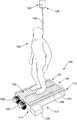
- FIG. 1shows an apparatus according to an embodiment of the disclosure
- FIG. 2shows a bottom view of the apparatus shown in FIG. 1 ;
- FIG. 3shows a bottom perspective view of one half of the apparatus shown in FIG. 1 ;
- FIG. 4shows a side cross-sectional view of the apparatus shown in FIG. 1 ;
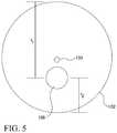
- FIG. 5shows a side view of a portion of the apparatus shown in FIG. 1 .
- the physical therapy apparatus of the present disclosurereduces physical harm to patients by preventing injuries from falling, while reconditioning overall mobility and reflexes. Specifically, the apparatus induces neuromuscular training through multiple simulations of powered slips and trips and natural slips and trips.
- a slipoccurs when a patient's center of mass shifts posteriorly leading the subject to land on his/her backside.
- a tripis the opposite type of fall in which the patient's center of mass shifts anteriorly, thereby causing the subject to land on his/her front-side.
- the apparatusincludes a roller table with two parallel columns of freely moving rollers positioned above a base having powered rollers.
- the roller tablerests on a lifting mechanism that can raise the roller table causing the freely moving rollers to disengage with the powered rollers, which allows the free motion rollers to transition from a powered treadmill to a highly slippery surface.
- the apparatusmay be in communication with a load cell for monitoring patient falls, speed and other parameters, instrumentation to adapt equipment setting based on patient responses and a central programmable logic controller (PLC) mounted to the base structure to control the equipment operations, an Ethernet switch to communicate patient output with a data processing system and a central data processing system to suggest patient treatments and track patient progress.
- PLCcentral programmable logic controller
- the apparatusis designed for patients to be used in a first mode, by walking on the roller table continuously in one direction like a treadmill.
- the apparatussimulates slippery conditions by disengaging the belt drive from the roller table, thereby reducing positive drive and allowing the individual rollers of the roller table to move freely, which results in patients having to manage highly slippery conditions, while supported from above by an external safety system.
- the roller tableoperates like a treadmill and the rollers are accelerated in a quick burst to cause the patient's feet to move from underneath their center of gravity and cause a forced fall.
- the apparatus 100includes a roller table 102 upon which a patient 150 may stand and walk.
- the roller table 102includes an outer frame 104 which supports a plurality of free motion rollers 106 in parallel.
- Each rolleris positioned to an adjacent roller with little space in between, such as less than 1/16 in., for example, to prevent any pinch points, and to provide the maximum amount of rollers to support the patient, and also to enable the roller table 102 to feel more like a flat walking surface.
- two columns 108 , 110 of rollers 106are positioned adjacent to each other within the outer frame 104 .
- the two columns of rollers 108 , 110are separated to allow independent rotation and free biaxial motion for each of the patient's feet.
- the free motion rollers 106are constructed of elastic and high friction material.
- the roller table 102is situated atop a base structure 112 .
- the base 112includes a first end 114 and a second end 116 .
- the base structure 112houses a plurality of powered rollers 118 and a lifting mechanism 130 , which are shown in FIGS. 2-4 and described in more detail below.
- two internal members 105 , 107are positioned within the base structure 112 extending from the first end 114 to the second end 116 .
- the powered rollers 118are positioned between the internal members 105 , 107 .
- the first end 114 of the base structureincludes first and second electrical motors 120 , 122 .
- the first motor 120provides power to the powered rollers 118 .
- the second motor 122provides power to the lifting mechanism 130 . In some embodiments, only one motor is used to power both the powered rollers 118 and the lifting mechanism 130 .
- the apparatus 100is in communication with a support structure 124 mounted to a ceiling of a physical therapy space.
- a load cell 126is located within or secured to the support structure 124 , and a safety cord 128 is connected to the load cell.
- the safety cord 128attaches to a safety harness or belt (not shown) worn by the patient 150 .
- the load cell 126senses and records the patient response to the equipment's stimuli, like changes in slope, speed of mode.
- the load cell 126is used to measure the amount of weight the patient relies on the safety structure during a fall. If no load is applied to the load cell, then no fall occurred. If the load cell measures less than half the weight of the patient, then the patient became off balance.
- the load cell 126If more than half the weight of the patient is measured by the load cell 126 , then the event is recorded as a fall.
- the fall event informationis recorded and can be utilized by a PLC (described below) to modify the number, type, or frequency of fall simulations.
- the load cell 126may be located within the safety harness or belt rather than in the support structure 124 .
- the apparatus 100also includes a programmable logic controller (PLC) 129 .
- the PLC 129is connected to the base structure 112 and in communication with the first motor 120 .
- the PLC 129is located in a panel mounted to the base structure 112 . It should be understood that in alternate embodiments, the PLC 129 may be secured to any part of the base structure 112 .
- the PLC 129controls the switching of the apparatus between the first mode, the second mode, and the third mode, as described in more detail below.
- the PLCcontrols the actuations and the transitions between the first, second, and third modes by using an algorithm that incorporates fall data recorded from the load cell 126 .
- the PLC 129has both a manually operated mode and an automated mode.
- a human machine interfaceHMI is needed to operate either mode and is linked to the PLC.
- the automated moderesponds to patient stimuli gathered through the load cell 126 and/or additional instrumentation. As the patients improve and respond positively to the slip inducing stimuli, then the automated mode may increase the speed or frequency of slip and powered fall simulations.
- the PLC 129also compiles rotational data from a motor encoder (not shown) with timer input to calculate the velocity of the patient, and records the downward force a patient places upon the safety harness during slip and trip events using the load cell 126 .
- FIG. 3a bottom view of the interior of a portion of the base structure 112 is shown.
- the plurality of powered rollers 118are positioned in parallel, and set to rest underneath and in between two free motion rollers 106 .
- One of the powered rollers 118is in contact with four (4) free motion rollers 106 , two parallel sets of adjacent free motion rollers, and so there are less powered rollers 118 than free motion rollers 106 present on the apparatus 100 .
- the outer frame 104 of the roller table 104is the same length as the base 112 , the outer frame 104 and the base 112 do not contact each other, because that would prevent the surfaces of the free motion rollers 106 from engaging with the surfaces of the powered rollers 118 .
- the first motor 120provides power to the powered rollers 118 , and is connected to the closest powered roller 118 through a chain or belt 121 .
- Two powered rollers 118are connected to one another via roller belts 119 .
- the roller belts 119rest in the gap that separates the two adjacent columns 108 , 110 of free motion rollers 106 from FIG. 1 .
- the surface of the powered rollers 118 and the free motion rollers 106may be slightly elastic and of high friction to assist the transfer of motion between the two while in treadmill mode.
- the lifting mechanism 130includes a plurality of elements positioned in each of the four interior corners of the base structure 112 .
- the lifting mechanismincludes four cams 132 that rotate and change the height of four vertical beams 134 .
- the vertical beams 134are secured in position at four blocks 136 , which are mounted to the inside wall of the base structure 112 .
- Motion of the cams 132is aligned by locking the two front cams together and the two back cams together with axles 138 .
- Motion between the axles 138is transferred using a chain 140 and sprockets 141 mounted to the end of the axles 138 .
- FIG. 4shows the apparatus 100 in a second position in which the lifting mechanism 130 has been actuated.
- the second electrical motor 122is used to power the lifting mechanism 130 .
- the second motor 122is connected to one of the axles 138 of the lifting mechanism 130 by a chain or belt 123 .
- the axles 138are positioned off center 133 within the outer circumference of the cams 132 , as shown in FIG. 5 .
- the cams 132when the cams 132 are rotated to a point where the larger radius r 1 is positioned closer to the roller table 102 and in line with the vertical beams 134 , the vertical beams 134 are raised or lifted upwardly toward the roller table 102 , which in turn lifts the roller table 102 upwardly and away from the base 112 , thereby disengaging contact between the powered rollers 118 and the free motion rollers 106 .
- wheels 139are mounted at the end of the vertical beams 134 between the vertical beams 134 and the cams 132 to help reduce friction and wear on the cams 132 .
- the wheels 139may be mounted onto the vertical beam 134 by a bolt or any other suitable fastener. Any non-rotational motion of the wheels 139 and the vertical beams 134 is prevented because the beams 134 are locked in a horizontal position by the location blocks 136 mounted to the base structure 112 . It should be understood that in alternate embodiments, any friction-reducing mechanism may be used instead of the wheels 139 .
- the lifting mechanism 130 of the present applicationdoes not include any pneumatic systems, thus reducing noise level of the apparatus, and also simplifying installation.
- the apparatus 100may operate in a first mode, which may be a walking or treadmill mode, a second mode, which may be a slip mode, and a third mode, which may be a trip mode.
- a first modewhich may be a walking or treadmill mode
- a second modewhich may be a slip mode
- a third modewhich may be a trip mode.
- the apparatus 100is in a starting position or stationary mode in which the roller table 102 is in a first position, where the free motion rollers 106 contact the powered rollers 118 .
- the cams 132are positioned with the smaller radius r 2 positioned closer to the roller table 102 and in line with the vertical beams 134 .
- either the PLC 129 or an operatortriggers a signal to start the apparatus 100 in a first, or treadmill mode.
- the speed of the first and second motors 120 , 122may be controlled and monitored by the PLC 129 .
- the first motor 120rotates, causing the chain or belt 121 to rotate the powered rollers 118 .
- the rotational motion of the powered rollers 118transfers to the free motion rollers 106 , causing them to rotate as well.
- the patient 150walks on the roller table 102 and remains at a constant position/height relative to the ground.
- the PLCcontrols the lifting mechanism 130 to transition the apparatus 100 from treadmill mode to the second or slippery mode.
- the second motor 122rotates, causing the axles 138 and the cams 132 of the lifting mechanism 130 to rotate.
- the second motor 122rotates a predetermined number of times.
- the vertical beams 134are lifted and therefore the roller table 102 is lifted about 1 ⁇ 4 in. vertically to disengage the free motion rollers 106 from the powered rollers 118 .
- the individual powered rollers 118can move freely.
- every roller, including free motion rollers 106 and powered rollers 118is free to move at extremely low friction. The patient is therefore only lifted slightly and should barely notice a change. The patient continues walking, but the surface is very slippery. The patient will therefore likely lose balance and fall.
- the load cell 126senses the fall and records the fall signal, which is sent to either the PLC 129 (in automated mode) or logged by an operator (in manual mode).
- the apparatus 100is then set back to the starting position or stationary mode.
- the roller table 102 and lifting mechanism 130are returned to their original positions.
- the roller table 102 and patient 150are lifted to ensure that during breakdowns, the roller table will remain in contact with the powered rollers 118 , and reduce the chance of a patient slipping on the free motion rollers 106 set in slippery mode. Also, the weight of the roller table 102 and patient 150 will generate sufficient friction between the surfaces of the free motion rollers 106 and the powered rollers 118 , thereby reducing slippage between the two sets of rollers while in the first, or treadmill mode.
- the apparatus 100can also operate in a third, trip mode.
- the powered rollers 118remain engaged with the free motion rollers 106 , and the powered rollers undergo a burst of increased acceleration, which causes an unexpected increase of the speed of the roller table 102 .
- the first motor 120can be configured to rotate either clockwise or counter-clockwise, allowing the powered rollers to roll either backward or forward.
- the patient 150continues walking, but at a much greater pace, and will therefore likely lose their balance and fall.
- the load cell 126senses the fall and records the fall signal, which is sent to either the PLC 129 (in automated mode) or logged by an operator (in manual mode).
- the apparatus 100is then set back to the starting position or stationary mode.
- the roller table 102 and lifting mechanism 130are returned to their original positions.
- the patientuses the apparatus 100 and patient data (such as, but not limited to, falls and imbalance events compared to simulation settings) gathered over time and is saved short term to a data logger connected to the PLC which is connected to all instrumentation.
- patient datasuch as, but not limited to, falls and imbalance events compared to simulation settings
- the operating algorithm on the PLCuses the patient data to modify treadmill speeds, directions and the frequency of slip mode and trip mode events.
- the patient datais uploaded to a network switch that patches it into a database or enterprise system, such as an Electronic Medical Record (EMR) system that stores the patients' history.
- EMRElectronic Medical Record
- the datais also sent to an enterprise program that evaluates the data from the session and sends a final report to the equipment to be received by the physical therapist or technician managing the patient.
- This reportprovides progress of the patient over a series of sessions using the equipment.
- the databasemay also provide additional input to a physical therapist recommending other procedures leading to better patient outcome.
- the apparatus disclosed hereinmay improve the excessive cost of fall injuries on our health system, while also improving quality of life for patients.
- the apparatusin another embodiment, includes a base that allows the roller table and wheels (or other cylinders) to move at low friction along one or two axes of travel and houses the cylinder, to simulate walking up, down, or horizontally along a hill. These changes in slope can also be used for balance training while the user is standing still.
- the apparatusis connected to the internet through a managed switch to provide an enterprise system with documentation of the results of the patient's therapy session.
Landscapes
- Health & Medical Sciences (AREA)
- Physical Education & Sports Medicine (AREA)
- General Health & Medical Sciences (AREA)
- Orthopedic Medicine & Surgery (AREA)
- Epidemiology (AREA)
- Pain & Pain Management (AREA)
- Rehabilitation Therapy (AREA)
- Life Sciences & Earth Sciences (AREA)
- Animal Behavior & Ethology (AREA)
- Public Health (AREA)
- Veterinary Medicine (AREA)
- Vascular Medicine (AREA)
- Cardiology (AREA)
- Rehabilitation Tools (AREA)
- Accommodation For Nursing Or Treatment Tables (AREA)
Abstract
Description
Claims (19)
Priority Applications (3)
| Application Number | Priority Date | Filing Date | Title |
|---|---|---|---|
| US15/971,409US10835777B2 (en) | 2017-05-05 | 2018-05-04 | Physical therapy apparatus and method of use |
| US16/677,870US11266893B2 (en) | 2017-05-05 | 2019-11-08 | Physical therapy apparatus and method of use |
| US17/687,815US11938377B2 (en) | 2017-05-05 | 2022-03-07 | Physical therapy apparatus and method of use |
Applications Claiming Priority (2)
| Application Number | Priority Date | Filing Date | Title |
|---|---|---|---|
| US201762501886P | 2017-05-05 | 2017-05-05 | |
| US15/971,409US10835777B2 (en) | 2017-05-05 | 2018-05-04 | Physical therapy apparatus and method of use |
Related Child Applications (1)
| Application Number | Title | Priority Date | Filing Date |
|---|---|---|---|
| US16/677,870Continuation-In-PartUS11266893B2 (en) | 2017-05-05 | 2019-11-08 | Physical therapy apparatus and method of use |
Publications (2)
| Publication Number | Publication Date |
|---|---|
| US20180318640A1 US20180318640A1 (en) | 2018-11-08 |
| US10835777B2true US10835777B2 (en) | 2020-11-17 |
Family
ID=64013901
Family Applications (1)
| Application Number | Title | Priority Date | Filing Date |
|---|---|---|---|
| US15/971,409ActiveUS10835777B2 (en) | 2017-05-05 | 2018-05-04 | Physical therapy apparatus and method of use |
Country Status (5)
| Country | Link |
|---|---|
| US (1) | US10835777B2 (en) |
| EP (1) | EP3618935B1 (en) |
| AU (1) | AU2018261004A1 (en) |
| CA (1) | CA3062458A1 (en) |
| WO (1) | WO2018204804A1 (en) |
Citations (35)
| Publication number | Priority date | Publication date | Assignee | Title |
|---|---|---|---|---|
| US3897119A (en) | 1971-11-01 | 1975-07-29 | Design Components Inc | Linear bearing slide |
| US4301914A (en) | 1977-09-09 | 1981-11-24 | Sandard Conveyor Company | Accumulating conveyor |
| US4342452A (en) | 1980-01-25 | 1982-08-03 | Summa H Wayne | Treadmill device |
| US5209240A (en) | 1991-02-20 | 1993-05-11 | Baltimore Therapeutic Co. | Device for inducing and registering imbalance |
| US5487444A (en) | 1993-03-23 | 1996-01-30 | Dennington; Mark | Shock-absorbing safety harness |
| US5569129A (en) | 1994-06-10 | 1996-10-29 | Mobility Research L.L.C. | Device for patient gait training |
| US5667461A (en) | 1994-07-06 | 1997-09-16 | Hall; Raymond F. | Ambulatory traction assembly |
| US6063046A (en) | 1997-04-11 | 2000-05-16 | Allum; John H. | Method and apparatus for the diagnosis and rehabilitation of balance disorders |
| US6152854A (en) | 1996-08-27 | 2000-11-28 | Carmein; David E. E. | Omni-directional treadmill |
| US6302828B1 (en) | 2000-01-28 | 2001-10-16 | Biodex Medical Systems, Inc. | Weight offloading apparatus |
| US6436009B1 (en) | 2001-04-23 | 2002-08-20 | Laurence Marucci | Treadmill fall prevention system |
| US20030153438A1 (en) | 2001-10-24 | 2003-08-14 | Keith Gordon | Closed-loop force controlled body weight support system |
| US20040009845A1 (en) | 2002-07-15 | 2004-01-15 | Johnson Reginald A. | Balance and gait training board |
| US20040116839A1 (en) | 2002-12-13 | 2004-06-17 | New Mexico Technical Research Foundation | Gait training apparatus |
| US20050209061A1 (en) | 2003-02-28 | 2005-09-22 | Nautilus, Inc. | Control system and method for an exercise apparatus |
| US20060052728A1 (en) | 2004-07-30 | 2006-03-09 | Kerrigan D C | Dynamic oscillating gait-training system |
| US20060211957A1 (en) | 2005-03-14 | 2006-09-21 | Laurent Beny | Device for mobilisation of the lower limbs |
| US20060247104A1 (en) | 2005-04-28 | 2006-11-02 | Mark Grabiner | Fall prevention training system and method using a dynamic perturbation platform |
| US7341025B1 (en) | 2006-04-06 | 2008-03-11 | Lucky Bums, Inc. | Gait training harness |
| US20090305853A1 (en) | 2008-06-08 | 2009-12-10 | Jordan Angela L | Randomly multidirectional devise and method for using the devise |
| US20100049105A1 (en)* | 2008-06-27 | 2010-02-25 | Constantinos Joannou | Whole body vibrator (ii) |
| KR20100079428A (en)* | 2008-12-31 | 2010-07-08 | 유인규 | The tilt apparatus of the golf hittng place |
| US7806807B2 (en) | 2005-11-08 | 2010-10-05 | Paul Genua | Exercise device for improving balance |
| US20100268129A1 (en) | 2007-09-10 | 2010-10-21 | Klmed Co., Ltd. | Gait trajectory guiding device of gait rehabilitation device |
| WO2010136924A1 (en) | 2009-05-28 | 2010-12-02 | Ben Gurion University Of The Negev Research And Development Authority | Balance perturbation system and trainer |
| US20110082012A1 (en) | 2009-10-01 | 2011-04-07 | Dynamic Fitness Equipment, Llc | Exercise device |
| US20110312473A1 (en) | 2005-04-28 | 2011-12-22 | Simbex Llc | Training system and method using a dynamic perturbation platform |
| US20140206503A1 (en)* | 2013-01-22 | 2014-07-24 | Gorbel, Inc. | Medical rehab lift system and method with horizontal and vertical force sensing and motion control |
| CA2942001A1 (en)* | 2013-03-14 | 2014-10-02 | Alex Formerly Known As Astilean Aurel ASTILEAN | Leg-powered treadmill |
| US20140336009A1 (en) | 2003-02-28 | 2014-11-13 | Nautilus, Inc. | Dual deck exercise device |
| US20160175643A1 (en)* | 2014-12-19 | 2016-06-23 | True Fitness Technology, Inc. | High-incline treadmill |
| US20160228746A1 (en) | 2015-02-09 | 2016-08-11 | Udai Jayakumar | Gait training apparatus and methodfor preventing or limiting injuries |
| US9616278B2 (en)* | 2014-08-29 | 2017-04-11 | Icon Health & Fitness, Inc. | Laterally tilting treadmill deck |
| US20170312582A1 (en)* | 2016-05-02 | 2017-11-02 | Southern Research Institute | Force Profile Control For The Application Of Horizontal Resistive Force |
| US20190105531A1 (en)* | 2017-10-06 | 2019-04-11 | Chieh-Ming Wu | Treadmill |
Family Cites Families (1)
| Publication number | Priority date | Publication date | Assignee | Title |
|---|---|---|---|---|
| HUP0900067A2 (en)* | 2009-02-05 | 2010-11-29 | Zsolt Szigetlaki | Walking platform preferably for virtual reality system |
- 2018
- 2018-05-04EPEP18795060.5Apatent/EP3618935B1/enactiveActive
- 2018-05-04CACA3062458Apatent/CA3062458A1/enactivePending
- 2018-05-04AUAU2018261004Apatent/AU2018261004A1/ennot_activeAbandoned
- 2018-05-04USUS15/971,409patent/US10835777B2/enactiveActive
- 2018-05-04WOPCT/US2018/031118patent/WO2018204804A1/ennot_activeCeased
Patent Citations (39)
| Publication number | Priority date | Publication date | Assignee | Title |
|---|---|---|---|---|
| US3897119A (en) | 1971-11-01 | 1975-07-29 | Design Components Inc | Linear bearing slide |
| US4301914A (en) | 1977-09-09 | 1981-11-24 | Sandard Conveyor Company | Accumulating conveyor |
| US4342452A (en) | 1980-01-25 | 1982-08-03 | Summa H Wayne | Treadmill device |
| US5209240A (en) | 1991-02-20 | 1993-05-11 | Baltimore Therapeutic Co. | Device for inducing and registering imbalance |
| US5337757A (en) | 1991-02-20 | 1994-08-16 | Baltimore Therapeutic Equipment Co. | Device for inducing and registering imbalance |
| US5487444A (en) | 1993-03-23 | 1996-01-30 | Dennington; Mark | Shock-absorbing safety harness |
| US5569129A (en) | 1994-06-10 | 1996-10-29 | Mobility Research L.L.C. | Device for patient gait training |
| US5667461A (en) | 1994-07-06 | 1997-09-16 | Hall; Raymond F. | Ambulatory traction assembly |
| US6152854A (en) | 1996-08-27 | 2000-11-28 | Carmein; David E. E. | Omni-directional treadmill |
| US6063046A (en) | 1997-04-11 | 2000-05-16 | Allum; John H. | Method and apparatus for the diagnosis and rehabilitation of balance disorders |
| US6302828B1 (en) | 2000-01-28 | 2001-10-16 | Biodex Medical Systems, Inc. | Weight offloading apparatus |
| US6436009B1 (en) | 2001-04-23 | 2002-08-20 | Laurence Marucci | Treadmill fall prevention system |
| US20030153438A1 (en) | 2001-10-24 | 2003-08-14 | Keith Gordon | Closed-loop force controlled body weight support system |
| US20040009845A1 (en) | 2002-07-15 | 2004-01-15 | Johnson Reginald A. | Balance and gait training board |
| US20040116839A1 (en) | 2002-12-13 | 2004-06-17 | New Mexico Technical Research Foundation | Gait training apparatus |
| US20050209061A1 (en) | 2003-02-28 | 2005-09-22 | Nautilus, Inc. | Control system and method for an exercise apparatus |
| US20140336009A1 (en) | 2003-02-28 | 2014-11-13 | Nautilus, Inc. | Dual deck exercise device |
| US20060052728A1 (en) | 2004-07-30 | 2006-03-09 | Kerrigan D C | Dynamic oscillating gait-training system |
| US20060211957A1 (en) | 2005-03-14 | 2006-09-21 | Laurent Beny | Device for mobilisation of the lower limbs |
| US20060247104A1 (en) | 2005-04-28 | 2006-11-02 | Mark Grabiner | Fall prevention training system and method using a dynamic perturbation platform |
| US20110312473A1 (en) | 2005-04-28 | 2011-12-22 | Simbex Llc | Training system and method using a dynamic perturbation platform |
| US20120108392A1 (en) | 2005-04-28 | 2012-05-03 | Simbex Llc | Training system and method using a dynamic perturbation platform |
| US7806807B2 (en) | 2005-11-08 | 2010-10-05 | Paul Genua | Exercise device for improving balance |
| US7341025B1 (en) | 2006-04-06 | 2008-03-11 | Lucky Bums, Inc. | Gait training harness |
| US20100268129A1 (en) | 2007-09-10 | 2010-10-21 | Klmed Co., Ltd. | Gait trajectory guiding device of gait rehabilitation device |
| US20090305853A1 (en) | 2008-06-08 | 2009-12-10 | Jordan Angela L | Randomly multidirectional devise and method for using the devise |
| US20100049105A1 (en)* | 2008-06-27 | 2010-02-25 | Constantinos Joannou | Whole body vibrator (ii) |
| KR20100079428A (en)* | 2008-12-31 | 2010-07-08 | 유인규 | The tilt apparatus of the golf hittng place |
| US8968161B2 (en) | 2009-05-28 | 2015-03-03 | Ben Gurion University Of The Negev Research And Development Authority | Balance perturbation system and trainer |
| US20120071300A1 (en) | 2009-05-28 | 2012-03-22 | Ben Gurion University Of The Negev Research And Development Authority | Balance perturbation system and trainer |
| WO2010136924A1 (en) | 2009-05-28 | 2010-12-02 | Ben Gurion University Of The Negev Research And Development Authority | Balance perturbation system and trainer |
| US20110082012A1 (en) | 2009-10-01 | 2011-04-07 | Dynamic Fitness Equipment, Llc | Exercise device |
| US20140206503A1 (en)* | 2013-01-22 | 2014-07-24 | Gorbel, Inc. | Medical rehab lift system and method with horizontal and vertical force sensing and motion control |
| CA2942001A1 (en)* | 2013-03-14 | 2014-10-02 | Alex Formerly Known As Astilean Aurel ASTILEAN | Leg-powered treadmill |
| US9616278B2 (en)* | 2014-08-29 | 2017-04-11 | Icon Health & Fitness, Inc. | Laterally tilting treadmill deck |
| US20160175643A1 (en)* | 2014-12-19 | 2016-06-23 | True Fitness Technology, Inc. | High-incline treadmill |
| US20160228746A1 (en) | 2015-02-09 | 2016-08-11 | Udai Jayakumar | Gait training apparatus and methodfor preventing or limiting injuries |
| US20170312582A1 (en)* | 2016-05-02 | 2017-11-02 | Southern Research Institute | Force Profile Control For The Application Of Horizontal Resistive Force |
| US20190105531A1 (en)* | 2017-10-06 | 2019-04-11 | Chieh-Ming Wu | Treadmill |
Non-Patent Citations (15)
| Title |
|---|
| Degelau, J. et al.; "Prevention of Falls (Acute Care)"; Institute for Clinical Systems Improvement; updated Apr. 2012. |
| International Search Report and Written Opinion for Int. App. No. PCT/US2018/031118, dated Jul. 12, 2018. |
| Luukinen, H., et al.; "Predictors for recurrent falls among the homedwelling elderly"; Scandinavian Journal of Primary Health Care, 13:4, pp. 294-299, 1995. |
| Oliver, D., et al.; "Risk factors and risk assessment tools for falls in hospital in-patients: a systemic review"; Age and Ageing, vol. 33, No. 2, pp. 122-130, 2004. |
| Pai, Y., et al.; "Perturbation Training Can Reduce Community-Dwelling Older Adults' Annual Fall Risk: a Randomized controlled Trial"; J Gerontol A Biol Sci Med Sci, vol. 69(12), pp. 1586-1594, Dec. 2014. |
| PCT International Search Report; International Searching Authority; dated Aug. 31, 2017, pp. 1-6, for International Application No. PCT/US2016/019458. |
| PCT International Written Opinion; International Searching Authority; dated Aug. 31, 2017, pp. 1-9, for International Application No. PCT/US2016/019458. |
| Salkeld, G., et al.; "Quality of life related to fear of falling and hip fracture in older women: a time trade off study"; BMJ, vol. 320, pp. 341-345, 2000. |
| Shang Y, Oct. 31, 2012, CN-202506048-U (Drawing and Abstract).* |
| Shumway-Cook, A., et al.; "Falls in the Medicare Population: Incidence, Associated Factors, and Impact on Health Care"; Physical Therapy, vol. 89, No. 4, pp. 324-332, 2009. |
| Wong, C.A., et al.; "The Cost of Serious Fall-Related Injuries at Three Midwestern Hospitals"; The Joint Commission Journal on Quality and Patient Safety, vol. 37, No. 2, pp. 81-87, 2011. |
| Yang, F., et al.; "Generalization of Treadmill-Slip Training to Prevent a Fall Following a Sudden (Novel) Slip in Over-Ground Walking"; J Biomech. vol. 46(1), pp. 63-69, 2013. |
| Yang, Feng, et al.; "Correction of the inertial effect resulting from a plate moving under low-friction conditions"; Journal of Biomechanics, 2007, vol. 40, pp. 2723-2730. |
| Yang, Feng, et al.; "Reduced intensity in gait-slip training can still improve stability"; Journal of Biomechanics, Apr. 2014, vol. 47, pp. 2330-2338. |
| Zhang M, Mar. 27, 2013,CN-102989120-A (Drawing and Abstract).* |
Also Published As
| Publication number | Publication date |
|---|---|
| AU2018261004A1 (en) | 2019-12-12 |
| EP3618935C0 (en) | 2024-07-03 |
| WO2018204804A1 (en) | 2018-11-08 |
| CA3062458A1 (en) | 2018-11-08 |
| US20180318640A1 (en) | 2018-11-08 |
| EP3618935A1 (en) | 2020-03-11 |
| EP3618935B1 (en) | 2024-07-03 |
| EP3618935A4 (en) | 2022-02-23 |
Similar Documents
| Publication | Publication Date | Title |
|---|---|---|
| US20190099639A1 (en) | Gait training apparatus and method for preventing or limiting injuries | |
| Borggraefe et al. | Sustainability of motor performance after robotic-assisted treadmill therapy in children: an open, non-randomized baseline-treatment study | |
| Cho et al. | Virtual-reality balance training with a video-game system improves dynamic balance in chronic stroke patients | |
| KR100793392B1 (en) | Early Rehabilitation Equipment | |
| EP1552492A2 (en) | Therapeutic exercise system and method for a paralyzed and nonparalyzed neuromusculoskeletal training system | |
| CN107822834A (en) | A kind of pedal lower limb rehabilitation robot of bilateral independent control | |
| US20140342877A1 (en) | Therapeutic exercise method and therapeutic exercise apparatus | |
| CN210698636U (en) | Cerebral infarction rehabilitation period nursing training device with timed reminding function | |
| CN112354134A (en) | Self-locking type space walker | |
| CN203790259U (en) | Liftable rotary recovery training apparatus | |
| CN112043564A (en) | Multifunctional medical rehabilitation equipment | |
| US10835777B2 (en) | Physical therapy apparatus and method of use | |
| CN102866640A (en) | Falling control system and rehabilitation shoe using same | |
| US11938377B2 (en) | Physical therapy apparatus and method of use | |
| US11266893B2 (en) | Physical therapy apparatus and method of use | |
| CN202983119U (en) | Integration movement training room for children | |
| Kegelmeyer et al. | Use of a robotic walking device for home and community mobility in Parkinson disease: a randomized controlled trial | |
| CN109549828B (en) | Walking aids for orthopedic nervous system rehabilitation | |
| CN108095918A (en) | Rehabilitation training robot | |
| CA3061370A1 (en) | Physical therapy apparatus and method of use | |
| CN103845185A (en) | Household small-size lower limb rehabilitation training robot | |
| CN113208867A (en) | Automatic rehabilitation machine for lower limb rehabilitation | |
| CN109260666B (en) | A lifting leg press device for sports | |
| CN220676356U (en) | Prevent surgical nursing that tumbles and help a kind of device | |
| CN202028115U (en) | Crawling type exercising machine |
Legal Events
| Date | Code | Title | Description |
|---|---|---|---|
| FEPP | Fee payment procedure | Free format text:ENTITY STATUS SET TO UNDISCOUNTED (ORIGINAL EVENT CODE: BIG.); ENTITY STATUS OF PATENT OWNER: SMALL ENTITY | |
| AS | Assignment | Owner name:SUREFOOTED LLC, ILLINOIS Free format text:ASSIGNMENT OF ASSIGNORS INTEREST;ASSIGNORS:TARAS, BRADFORD;JAYAKUMAR, UDAI;SIGNING DATES FROM 20180503 TO 20180508;REEL/FRAME:045767/0189 | |
| FEPP | Fee payment procedure | Free format text:ENTITY STATUS SET TO SMALL (ORIGINAL EVENT CODE: SMAL); ENTITY STATUS OF PATENT OWNER: SMALL ENTITY | |
| STPP | Information on status: patent application and granting procedure in general | Free format text:DOCKETED NEW CASE - READY FOR EXAMINATION | |
| STPP | Information on status: patent application and granting procedure in general | Free format text:NON FINAL ACTION MAILED | |
| STPP | Information on status: patent application and granting procedure in general | Free format text:RESPONSE TO NON-FINAL OFFICE ACTION ENTERED AND FORWARDED TO EXAMINER | |
| STPP | Information on status: patent application and granting procedure in general | Free format text:NOTICE OF ALLOWANCE MAILED -- APPLICATION RECEIVED IN OFFICE OF PUBLICATIONS | |
| STPP | Information on status: patent application and granting procedure in general | Free format text:DOCKETED NEW CASE - READY FOR EXAMINATION | |
| STPP | Information on status: patent application and granting procedure in general | Free format text:NOTICE OF ALLOWANCE MAILED -- APPLICATION RECEIVED IN OFFICE OF PUBLICATIONS | |
| STCF | Information on status: patent grant | Free format text:PATENTED CASE | |
| FEPP | Fee payment procedure | Free format text:SURCHARGE FOR LATE PAYMENT, SMALL ENTITY (ORIGINAL EVENT CODE: M2554); ENTITY STATUS OF PATENT OWNER: SMALL ENTITY | |
| MAFP | Maintenance fee payment | Free format text:PAYMENT OF MAINTENANCE FEE, 4TH YR, SMALL ENTITY (ORIGINAL EVENT CODE: M2551); ENTITY STATUS OF PATENT OWNER: SMALL ENTITY Year of fee payment:4 |