US10835772B2 - Sprinkler drop bracket for intersecting downlight - Google Patents
Sprinkler drop bracket for intersecting downlightDownload PDFInfo
- Publication number
- US10835772B2 US10835772B2US16/540,544US201916540544AUS10835772B2US 10835772 B2US10835772 B2US 10835772B2US 201916540544 AUS201916540544 AUS 201916540544AUS 10835772 B2US10835772 B2US 10835772B2
- Authority
- US
- United States
- Prior art keywords
- main body
- suspension frame
- bracket assembly
- sprinkler
- seating
- Prior art date
- Legal status (The legal status is an assumption and is not a legal conclusion. Google has not performed a legal analysis and makes no representation as to the accuracy of the status listed.)
- Active
Links
Images


Classifications
- A—HUMAN NECESSITIES
- A62—LIFE-SAVING; FIRE-FIGHTING
- A62C—FIRE-FIGHTING
- A62C35/00—Permanently-installed equipment
- A62C35/58—Pipe-line systems
- A62C35/68—Details, e.g. of pipes or valve systems
- B—PERFORMING OPERATIONS; TRANSPORTING
- B05—SPRAYING OR ATOMISING IN GENERAL; APPLYING FLUENT MATERIALS TO SURFACES, IN GENERAL
- B05B—SPRAYING APPARATUS; ATOMISING APPARATUS; NOZZLES
- B05B15/00—Details of spraying plant or spraying apparatus not otherwise provided for; Accessories
- B05B15/60—Arrangements for mounting, supporting or holding spraying apparatus
- B05B15/62—Arrangements for supporting spraying apparatus, e.g. suction cups
- E—FIXED CONSTRUCTIONS
- E04—BUILDING
- E04B—GENERAL BUILDING CONSTRUCTIONS; WALLS, e.g. PARTITIONS; ROOFS; FLOORS; CEILINGS; INSULATION OR OTHER PROTECTION OF BUILDINGS
- E04B9/00—Ceilings; Construction of ceilings, e.g. false ceilings; Ceiling construction with regard to insulation
- E04B9/06—Ceilings; Construction of ceilings, e.g. false ceilings; Ceiling construction with regard to insulation characterised by constructional features of the supporting construction, e.g. cross section or material of framework members
- E04B9/12—Connections between non-parallel members of the supporting construction
- E04B9/14—Connections between non-parallel members of the supporting construction all the members being discontinuous and laying at least partly in the same plane
- F—MECHANICAL ENGINEERING; LIGHTING; HEATING; WEAPONS; BLASTING
- F16—ENGINEERING ELEMENTS AND UNITS; GENERAL MEASURES FOR PRODUCING AND MAINTAINING EFFECTIVE FUNCTIONING OF MACHINES OR INSTALLATIONS; THERMAL INSULATION IN GENERAL
- F16L—PIPES; JOINTS OR FITTINGS FOR PIPES; SUPPORTS FOR PIPES, CABLES OR PROTECTIVE TUBING; MEANS FOR THERMAL INSULATION IN GENERAL
- F16L3/00—Supports for pipes, cables or protective tubing, e.g. hangers, holders, clamps, cleats, clips, brackets
- F16L3/003—Supports for pipes, cables or protective tubing, e.g. hangers, holders, clamps, cleats, clips, brackets devices for holding the open end of a hose
- E—FIXED CONSTRUCTIONS
- E04—BUILDING
- E04B—GENERAL BUILDING CONSTRUCTIONS; WALLS, e.g. PARTITIONS; ROOFS; FLOORS; CEILINGS; INSULATION OR OTHER PROTECTION OF BUILDINGS
- E04B9/00—Ceilings; Construction of ceilings, e.g. false ceilings; Ceiling construction with regard to insulation
- E04B9/006—Ceilings; Construction of ceilings, e.g. false ceilings; Ceiling construction with regard to insulation with means for hanging lighting fixtures or other appliances to the framework of the ceiling
Definitions
- the present disclosurerelates to fire protection sprinkler drop support systems and, more particularly, to a sprinkler drop bracket for an intersecting downlight.
- a typical automatic fire sprinkler systemincludes a network of pipes that carry a fire suppression fluid, e.g., water, to one or more rooms in a building. Conduit sections carry the fluid from the pipes to sprinkler heads strategically located in different rooms. The position and orientation of each sprinkler head is typically maintained in place by a support assembly. When the room reaches an elevated temperature due to a fire, the sprinkler head is activated, allowing a stream of fire suppression fluid to be directed over the intended area of coverage. The support assembly is used to hold the sprinkler securely in place during operation.
- a fire suppression fluide.g., water
- Some known sprinkler support assembliesare designed to be secured to a ceiling structure by fasteners.
- the sprinkler headtypically extends through an opening in a central area of one or more ceiling tiles. This may be undesirable, however, in grid-type ceiling systems employing lighting fixtures (e.g., downlights) at an intersection of two or more ceiling tiles.
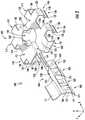
- FIG. 1One such prior art ceiling system is shown in FIG. 1 .
- the ceiling system 10includes a downlight suspension frame 12 connecting 4 (four) ceiling grid supports 14 .
- the downlight suspension frame 12 and ceiling grid supports 14are coupled to a yoke 18 , which is suspended by a wire or cable 20 .
- the yoke 18may be secured atop two or more ceiling grid supports 14 by a set of brackets 24 .
- a lighting fixture(not shown) may be disposed within a central area 30 of the downlight suspension frame 12 to illuminate an area below the ceiling system 10 .
- bracketfor coupling a fire sprinkler assembly to a downlight suspension frame of a ceiling grid system, wherein the bracket is easier to install and meets all fire safety industry requirements.
- One approach according to the disclosureincludes a fire sprinkler support assembly having a suspension frame coupled between a plurality of ceiling grid support elements, and a bracket assembly coupled to the suspension frame and to at least one of the plurality of ceiling grid support elements.
- the bracket assemblymay include a main body coupled to the suspension frame, and a support arm extending laterally from the main body, the support arm including a set of seating members coupled to the at least one of the plurality of ceiling grid support elements.
- the fire sprinkler support assemblyfurther includes a sprinkler drop coupled to the support arm, the sprinkler drop extending through the main body and into the suspension frame.
- Bracket assemblyhaving a main body coupled to a lighting fixture suspension frame by a first set of seating members, the main body including a central opening for receiving a sprinkler drop.
- the bracket assemblyfurther includes a support arm extending laterally from the main body, the support arm including a shaft and a second set of seating members extending from the shaft for coupling the support arm to a ceiling grid support element.
- a fire sprinkler support assemblyhaving a suspension frame coupled at an intersection of a plurality of ceiling grid support elements, and a bracket assembly coupled to the suspension frame and to at least one of the plurality of ceiling grid support elements.
- the bracket assemblymay include a main body extending partially into the suspension frame, the main body including a first set of seating members and a central opening, and a support arm extending laterally from the main body, the support arm including a second set of seating members coupled to the at least one of the plurality of ceiling grid support elements.
- Still yet another approach according to the disclosureincludes a fire sprinkler support assembly having a suspension frame centrally coupled between a plurality of ceiling grid support elements, and a bracket assembly coupled atop the suspension frame.
- the bracket assemblymay include a sprinkler head disposed within a central opening of the suspension frame.
- Still yet another approach according to the disclosureincludes a method for mounting a bracket assembly on a suspension frame.
- the methodcan include attaching a main body of the bracket assembly to the suspension frame; and attaching a support arm of the bracket assembly to a ceiling grid support element of the suspension frame.
- the support armcan extend outward from the main body.
- FIG. 1is a perspective view of a prior art ceiling system including a downlight suspension frame connecting a set of ceiling grid supports;
- FIG. 2is a perspective view of a bracket assembly according to approaches of the disclosure
- FIG. 3is a bottom view of the bracket assembly of FIG. 2 according to approaches of the disclosure
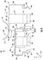
- FIG. 4is an end view of the bracket assembly of FIG. 2 according to approaches of the disclosure
- FIG. 5is a perspective view of a fire sprinkler support assembly according to approaches of the disclosure.
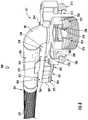
- FIG. 6is a perspective view of a bracket assembly according to approaches of the disclosure.
- any reference to direction or orientationis merely intended for convenience of description and is not intended in any way to limit the scope of the present invention.
- Relative termssuch as “lower,” “upper,” “horizontal,” “vertical,”, “above,” “below,” “up,” “down,” “top” and “bottom” as well as derivative thereof (e.g., “horizontally,” “downwardly,” “upwardly,” etc.) should be construed to refer to the orientation as then described or as shown in the drawing under discussion. These relative terms are for convenience of description only and do not require that the apparatus be constructed or operated in a particular orientation.
- a sprinkler support assemblyfor use with a fire suppression device.
- a sprinkler support assemblyincludes a suspension frame coupled to a plurality of ceiling grid support elements, and a bracket assembly coupled to the suspension frame and to at least one of the plurality of ceiling grid support elements.
- the bracket assemblymay include a main body extending partially into a central area of the suspension frame, the main body including a first set of seating members and a central opening.
- the bracket assemblymay further include a support arm extending laterally from the main body, the support arm including a second set of seating members coupled to the at least one of the plurality of ceiling grid support elements.
- the sprinkler support assemblymay be a retrofit solution that couples to an existing suspension frame of a downlight fixture.
- Embodiments of the disclosureare compatible with a ceiling system including an overhead ceiling grid support system configured to be mounted in a suspended manner from an overhead building support structure via suitable hanger elements, such as for example, without limitation, fasteners, hangers, wires, cables, rods, struts, etc.
- the overhead ceiling grid support systemincludes a plurality of grid support members intersecting at a lighting fixture suspension frame.
- the ceiling grid support elements and/or the suspension framemay be hung by one or more hanger elements from the overhead building support structure and provide support for a portion of a fire suppression system, e.g., a sprinkler drop, a sprinkler heard, etc.
- the ceiling grid support elementsmay be arranged to form an array of grid openings which receive and are essentially closed by ceiling tiles or panels when positioned within the grid openings.
- ceiling grid support elementsmay be arranged in an orthogonal pattern and intersect at right angles (i.e. perpendicular) to form the grid openings which are rectilinear, such as squares or rectangles (in top plan view).
- the grid openingsmay be substantially coextensive with the length and width of the ceiling panels to be installed in the grid openings.
- the ceiling panelsmay be any type of ceiling panel, including without limitation, square edge panels, stepped tegular edge panels creating a reveal, or other.
- the ceiling panelsmay be constructed of any suitable material or combinations of different materials. Some non-limiting examples of ceiling panel materials that may be used include, without limitation, mineral fiber board, fiberglass, metals, polymers, wood, composites, combinations thereof, or other.
- Exemplary embodiments of bracket assemblies for fire sprinkler support assemblies described hereinmay be designed for a T-bar suspended beam.
- an installercan “snap” the bracket assembly into place.
- the installercan further secure/anchor the bracket assembly to the T-bar beam using one or more fasteners.
- the installermay disengage/loosen/release the fastener to unlock the seating frame from the T-bar beam.
- the bracket assembly 100may include a main body 102 coupleable with a suspension frame (e.g., a downlight suspension frame), and a support arm 104 extending laterally (e.g., along the x-axis) from the main body 102 .
- a suspension framee.g., a downlight suspension frame
- a support arm 104extending laterally (e.g., along the x-axis) from the main body 102 .
- the support arm 104 and the main body 102may support a sprinkler drop of a fire suppression system.
- the main body 102may include a first set of seating members 108 - 114 (also referred to herein as “main body seating members”) extending from an outer perimeter 116 , and a central opening 118 including at least one fastener 120 (e.g., clip or clasp) for securing the sprinkler drop therein.
- a fastener 120e.g., clip or clasp
- the main body 102 and the support arm 104may be made of a suitable material including metal and non-metal.
- the bracket assembly 100is made of a flat metal plate or sheet of material formed to shape, such as without limitation aluminum, titanium, steel.
- the bracket assembly 100is made of cold rolled steel which may be coated for corrosion resistance.
- the main body 102 and the support arm 104may have the same or different thicknesses.
- the bracket assembly 100may be formed and machined by any suitable metal fabrication method such as bending, stamping, rolling, forging, casting, cutting, milling, welding, soldering, or combinations thereof.
- a non-metal bracket assembly 100may be formed by suitable methods, including without limitation, molding and others.
- the main body 102includes first and second sections 121 , 122 on opposite sides of the central opening 118 .
- a top surface 124 of the first section 121defines a first plane (e.g., x-z plane), and a top surface 125 of the second section 122 defines a second plane (e.g., x-z plane), wherein the first plane and the second plane are parallel to one another.
- the first and second sections 121 , 122are connected by risers 127 and 128 , which may be oriented perpendicular to the first and second planes.
- the top surface 124 of the first section 121is vertically higher (e.g., along the y-axis) than the top surface 125 of the second section 122 so as to provide additional support for the sprinkler drop.
- each of the first set of seating members 108 - 114extends laterally (e.g., along x-axis and z-axis) from the perimeter 116 of the main body 102 . More specifically, each of seating members 108 - 111 of the second section 122 includes a first section 130 extending outwardly from the main body 102 , for example, along the second plane defined by the top surface 125 . A second section 132 extends perpendicularly, or substantially perpendicularly, from the first section 130 , and a third section 134 extends from the second section 132 .
- the third section 134 of seating members 109 - 111includes an upper section 136 , a free end 137 , and a protrusion 138 extending between the upper section 136 and the free end 137 .
- the protrusion 138extends outwardly away from the main body 102 , and may be aligned with and engage an opening in a sidewall of the suspension frame.
- the third section 134 of the seating member 108includes only an extension member 140 , which extends downward (e.g., along the y-axis), parallel to the second section 132 .
- the extension member 140is configured to engage an exterior surface of the suspension frame to provide further stability to the main body 102 .
- each of seating members 112 - 114 of the first section 121includes a first section 142 extending outwardly from the main body 102 , for example, along the first plane defined by the top surface 124 .
- a second section 144extends perpendicularly, or substantially perpendicularly, from the first section 142
- a third section 146extends from the second section 144 .
- the third section 146 of seating members 112 - 114includes an upper section 147 , a free end 148 , and a protrusion 149 extending between the upper section 147 and the free end 148 .
- each of the seating members 109 - 114extends vertically down to a same depth. Meanwhile, seating member 108 is generally shorter than seating members 109 - 114 , and extends partially along an exterior of the suspension frame.
- the central opening 118 of the main body 102may be snail-shaped.
- a perimeter 155 defining central opening 118includes a laterally extending irregularity or jut 156 provided to enable the main body 102 to be manufactured, for example, in the case the main body 102 is being made out of one piece of stamped steel and then folded.
- the main body 102includes a fasteners 120 disposed along the perimeter 155 on opposite sides of the central opening 118 . The fasteners 120 engage/retain the sprinkler drop within the main body 102 . In various embodiments, a variety of fasteners may be used to similarly hold the sprinkler drop in place.
- the support arm 104includes a shaft 158 and a second set of seating members 160 - 163 extending from the shaft 158 .
- the shaft 158is oriented perpendicular to the main body 102 , and generally extends from the riser 127 between the first and second sections 121 , 122 of the main body 102 .
- the shaft 158is aligned with the central opening 118 of the main body 102 to provide the sprinkler drop to the central opening 118 once assembled.
- the seating members 160 - 163extend downwardly from a bottom side 164 of the shaft 158 for engagement with a ceiling grid support element.
- Each of the seating members 160 - 163includes a first section 166 , which may be curved, extending outwardly (e.g., along the z-axis) from the shaft 158 , and a second section 167 extending from the first section 166 .
- the second section 167is generally flat, and extends below the shaft 158 .
- the second section 167may be substantially parallel to the shaft 158 .
- a third section 175extends from the second section 167 , and may be bent, angled, and/or include a protrusion 177 to engage the ceiling grid support element.
- the seating members 160 - 163are offset relative to one another so that the seating members 160 - 163 straddle the ceiling grid support element.
- one or more of the seating members 160 - 163may include an opening 169 to permit engagement with one or more fasteners used to secure the support arm 104 to the ceiling grid support element.
- four (4) seating membersare shown, a greater or fewer number of seating members may be employed in alternative embodiments.
- the support arm 104further includes a set of clamp members 171 , 172 extending from an upper side 173 of the shaft 158 .
- the clamp members 170 , 171may be curved and extend upwardly and outwardly from the support arm 104 .
- the clamp members 171 , 172may extend outwardly in different directions (e.g., along the z-axis) relative to one another so that the clamp members 171 , 172 support the sprinkler drop.
- two (2) clamp membersare shown, a greater or fewer number clamp members may be employed in alternative embodiments.
- FIG. 5illustrates the entire support assembly 200
- FIG. 6illustrates the support assembly 200 with certain components removed to better illustrate a fire sprinkler assembly 265 coupled to a bracket assembly 211
- the bracket assembly 211which may be the same or similar to the bracket assembly 100 of FIGS. 2-4 , may be coupled to a suspension frame 235 and to a ceiling system 250 including one or more ceiling grid support elements 201 , 203 , 205 , and 207 .
- the ceiling grid support elements 201 , 203 , 205 , and 207may be arranged to form an array of grid openings which receive and are essentially closed by ceiling tiles or panels (not shown) when positioned within the grid openings.
- Each of the ceiling grid support elements 201 , 203 , 205 , and 207may be t-shaped in a transverse cross-section and include a longitudinally-extending horizontal bottom flange 217 , an enlarged stiffening channel 219 (also referred to as a bulb), and a vertical web 221 extending between the bottom flange 217 and the stiffening channel 219 .
- the stiffening channel 219may be excluded.
- the bottom flange 217has opposing portions which extend laterally outwards from the web 221 and terminate in opposed axially extending longitudinal edges.
- the web 221may be centered between the longitudinal edges and vertically aligned beneath the stiffening channel 219 .
- the bottom flange 217also includes a top surface 223 and a bottom surface 229 , wherein the top surface 223 provides a ledge for positioning and supporting a plurality of ceiling panels (not shown) thereupon.
- the ceiling system 250may include a yoke 241 connected between two or more of ceiling grid support elements 201 , 203 , 205 , and 207 .
- the yoke 241may be secured to ceiling grid support elements 203 and 207 by one or more brackets 243 , wherein the yoke 241 may be connected to a ceiling structure by a wire or cable (not shown).
- the brackets 243may include a seating frame directly coupled to each ceiling grid support element 203 and 207 , wherein the seating frame includes first and second seating members disposed on opposite sides of each ceiling grid support elements 203 and 207 . In some embodiments, the first and second seating members straddle ceiling grid support elements 203 and 207 .
- the seating frame of the brackets 243provides stability to the support assembly yoke 241 .
- the yoke 241may be provided to support all components of the sprinkler support assembly 200 .
- some or all of the ceiling grid support elements 201 , 203 , 205 , and 207may also be suspended from an overlying building structure using, for example, flexible wire, and may be configured according to ASTM International standards.
- the standardsmay include, but are not limited to, those set forth in one or more of designations C635, C636 and E580, which are each incorporated herein by reference.
- each of the ceiling grid support elements 201 , 203 , 205 , and 207are joined together by a suspension frame 235 .
- the suspension frame 235may be positioned centrally at an intersection of the ceiling grid support elements 201 , 203 , 205 , and 207 , wherein a set of connection clips 239 extend through a sidewall 233 of the suspension frame 235 to provide a code compliant connection therebetween.
- the suspension frame 235further provides a central area/opening 273 for either a downlight or a sprinkler head 274 .
- the suspension frame 235may have a generally rectangular shape (top plan view) defined by the sidewall 233 , and a cover (not shown) over the sprinkler head 274 .
- the cover and the lower part of the suspension frame 235may extend below a plurality of ceiling tiles (not shown) supported by an upper surface 259 of a ridge 261 extending around an outer surface of the sidewall 233 . In the event of a fire, the cover is easily displaced.
- the suspension frame 235may be suitable for use with an LED downlight.
- the suspension frame 235is used to support the fire sprinkler assembly 265 including supply pipes (not shown) and a sprinkler drop 285 , which may be part of a fire suppression fluid delivery system.
- the sprinkler drop 285includes an elbow 281 coupled to the sprinkler head 274 , which is surrounded by a baffle 276 , and which is housed within the central area/opening 273 of the suspension frame 235 .
- a thermally responsive device of the sprinkler headreacts to heat generated by the fire to allow fluid (e.g., water, nitrogen, and/or halogen) to flow through the sprinkler drop 285 and into the sprinkler head 274 , where the fluid is dispersed outwardly to extinguish the fire.
- fluide.g., water, nitrogen, and/or halogen
- the sprinkler drop 285is connected to a flexible conduit 277 including a flexible portion that comprises, for example, a corrugated tube, a hose, or a braided tube, which can be made from known materials including metal, rubber, etc.
- the flexible conduit 277is corrugated metal with a braided metal covering.
- the flexible conduit 277may be flexible along its entire length, or may include one or more flexible portions adjacent more rigid portions.
- the flexible conduitmay have a low elasticity so that when bent into a desired position, the flexible conduit it maintains its shape and does not return to its original position.
- the conduitmay be rigid or substantially rigid.
- the main body 202 of the bracket assembly 211is coupled to the suspension frame 235 , and the support arm 204 extends laterally (e.g., along the x-axis) from the main body 202 to support the sprinkler drop 285 .
- the main body 202includes a first set of seating members 208 - 214 extending laterally (e.g., along x-axis and z-axis) from the perimeter 216 of the main body 202 . More specifically, each of seating members 208 - 214 includes a first section 230 extending outwardly from the main body 202 , for example, along a plane defined by a top surface of the main body 202 .
- a second section 232extends perpendicularly, or substantially perpendicularly, from the first section 230 , and a third section 234 extends from the second section 232 .
- the third section 234includes a protrusion extending into an opening 280 in the sidewall 233 of the suspension frame 235 to align and secure the main body 202 to the suspension frame 235 .
- the third section 234 of seating member 208extends along the exterior surface of the sidewall 233 to provide further support for the main body 202 .
- one or more of the first set of seating members 208 - 214engages a top surface 286 of the sidewall 233 of the suspension frame 235 .
- seating members 208 - 214extend laterally beyond the sidewall 233 (e.g., in the x-z plane) to support the main body 202 and the sprinkler drop 285 .
- the support arm 204includes a shaft 258 and a second set of seating members 260 - 263 extending from the shaft 258 .
- the support arm 204extends along a lengthwise axis (e.g., the x-axis) of the ceiling grid support element 201 , wherein the lengthwise axis generally traverses along the vertical web 221 and/or the stiffening channel 219 , between the flexible conduit 277 and the suspension frame 235 .
- the shaft 258is oriented perpendicular to the main body 202 , and is aligned with the central opening of the main body 202 to guide the sprinkler drop 285 through the central opening during assembly.
- the seating members 260 - 263generally extend downwardly from a bottom side 264 of the shaft 258 for engagement with ceiling grid support element 201 . More specifically, a first section 266 and a second section 267 of each seating member 260 - 263 engages the stiffening channel 219 , while a third section 275 engages the web 221 of ceiling grid support element 201 . As arranged, the seating members 260 - 263 are offset relative to one another so that the seating members 260 - 263 are disposed on opposite sides of the ceiling grid support element 201 .
- the support arm 204further includes the set of clamp members 271 , 272 extending from the upper side 278 of the shaft 258 .
- the clamp members 271 , 272may be curved and extend upwardly and outwardly from the shaft 258 to support the sprinkler drop 285 . As shown, the clamp members 271 , 272 may extend in opposite directions to cradle the sprinkler drop 285 therebetween.
- the fire sprinkler assembly 265In order to function effectively, the fire sprinkler assembly 265 must be held firmly in place during operation. Due to the significant back pressure of the fluid flowing therethrough, the sprinkler drop 285 may be subjected to significant side, rotational, and torsional forces, which are capable of changing the position of the fire sprinkler head extending from the sprinkler drop, thereby causing the fluid to be directed away from the intended target. It will be appreciated that the bracket assembly 211 is configured to resist movement of the sprinkler drop 285 by distributing the forces to the ceiling grid support elements 201 , 203 , 205 , and 207 via the support arm 204 and the main body 202 .
- each of the herein described bracket assemblies 100 , 211may include a barrier layer provided along one or more surfaces thereof.
- a barrier layer including a set of plastic insertsmay be formed along outer surfaces of the first and second sets of seating members.
- the plastic insertsmay be open at a top thereof, and extend around the lower surfaces of the first and second sets of seating members. The inserts may increase durability and reduce friction between the first and second sets of seating member sand the beams of the ceiling system.
- the plastic insertsmay be useful for low-voltage suspended ceiling power distribution systems in which screws on the ceiling grids should not be used.
- bracket assemblymay be retrofit to existing downlight lighting suspension frames, thus providing symmetrical placement of sprinkler heads relative to lighting fixtures in grid-type ceiling systems employing lighting fixtures (e.g., downlights) at an intersection of two or more ceiling tiles.
Landscapes
- Engineering & Computer Science (AREA)
- Architecture (AREA)
- Emergency Management (AREA)
- Health & Medical Sciences (AREA)
- Business, Economics & Management (AREA)
- Public Health (AREA)
- Physics & Mathematics (AREA)
- Electromagnetism (AREA)
- Civil Engineering (AREA)
- Structural Engineering (AREA)
- General Engineering & Computer Science (AREA)
- Mechanical Engineering (AREA)
- Fire-Extinguishing By Fire Departments, And Fire-Extinguishing Equipment And Control Thereof (AREA)
Abstract
Description
Claims (18)
Priority Applications (1)
| Application Number | Priority Date | Filing Date | Title |
|---|---|---|---|
| US16/540,544US10835772B2 (en) | 2017-06-08 | 2019-08-14 | Sprinkler drop bracket for intersecting downlight |
Applications Claiming Priority (3)
| Application Number | Priority Date | Filing Date | Title |
|---|---|---|---|
| US15/617,389US10010731B1 (en) | 2017-06-08 | 2017-06-08 | Sprinkler drop bracket for intersecting downlight |
| US15/987,355US10426985B2 (en) | 2017-06-08 | 2018-05-23 | Sprinkler drop bracket for intersecting downlight |
| US16/540,544US10835772B2 (en) | 2017-06-08 | 2019-08-14 | Sprinkler drop bracket for intersecting downlight |
Related Parent Applications (1)
| Application Number | Title | Priority Date | Filing Date |
|---|---|---|---|
| US15/987,355DivisionUS10426985B2 (en) | 2017-06-08 | 2018-05-23 | Sprinkler drop bracket for intersecting downlight |
Publications (2)
| Publication Number | Publication Date |
|---|---|
| US20190366139A1 US20190366139A1 (en) | 2019-12-05 |
| US10835772B2true US10835772B2 (en) | 2020-11-17 |
Family
ID=62684351
Family Applications (4)
| Application Number | Title | Priority Date | Filing Date |
|---|---|---|---|
| US15/617,389ActiveUS10010731B1 (en) | 2017-06-08 | 2017-06-08 | Sprinkler drop bracket for intersecting downlight |
| US15/987,355ActiveUS10426985B2 (en) | 2017-06-08 | 2018-05-23 | Sprinkler drop bracket for intersecting downlight |
| US16/540,612ActiveUS10799739B2 (en) | 2017-06-08 | 2019-08-14 | Sprinkler drop bracket for intersecting downlight |
| US16/540,544ActiveUS10835772B2 (en) | 2017-06-08 | 2019-08-14 | Sprinkler drop bracket for intersecting downlight |
Family Applications Before (3)
| Application Number | Title | Priority Date | Filing Date |
|---|---|---|---|
| US15/617,389ActiveUS10010731B1 (en) | 2017-06-08 | 2017-06-08 | Sprinkler drop bracket for intersecting downlight |
| US15/987,355ActiveUS10426985B2 (en) | 2017-06-08 | 2018-05-23 | Sprinkler drop bracket for intersecting downlight |
| US16/540,612ActiveUS10799739B2 (en) | 2017-06-08 | 2019-08-14 | Sprinkler drop bracket for intersecting downlight |
Country Status (2)
| Country | Link |
|---|---|
| US (4) | US10010731B1 (en) |
| WO (1) | WO2018226525A1 (en) |
Families Citing this family (7)
| Publication number | Priority date | Publication date | Assignee | Title |
|---|---|---|---|---|
| US10962207B2 (en)* | 2016-04-25 | 2021-03-30 | Worthington Armstrong Venture | Hub for lighting at grid intersection |
| US10527203B2 (en) | 2016-10-12 | 2020-01-07 | Anvil International, Llc | Snap to grid bracket for a sprinkler support assembly |
| US10561872B2 (en)* | 2016-11-17 | 2020-02-18 | Anvil International, Llc | Fire sprinkler assembly including adjustable drop |
| US10010731B1 (en) | 2017-06-08 | 2018-07-03 | Anvil International, Llc | Sprinkler drop bracket for intersecting downlight |
| US10610716B2 (en) | 2017-06-08 | 2020-04-07 | Anvil International, Llc | Sprinkler drop bracket for intersecting downlight |
| CA3064208A1 (en)* | 2018-12-12 | 2020-06-12 | Andrew Cook | Clip hanger and ceiling suspension system incorporating same |
| EP4304742A1 (en) | 2021-03-08 | 2024-01-17 | Tyco Fire Products LP | Systems and methods for sprinkler systems with flexible hose and rapid seal adapter |
Citations (80)
| Publication number | Priority date | Publication date | Assignee | Title |
|---|---|---|---|---|
| US796178A (en)* | 1904-09-09 | 1905-08-01 | Beaton & Anderson | Pipe-hanger. |
| US833613A (en)* | 1905-10-11 | 1906-10-16 | Charles P Maiser | Pipe-hanger. |
| US949576A (en)* | 1909-09-16 | 1910-02-15 | Robert C Hunter | Pipe-hanger. |
| US3536281A (en) | 1968-01-04 | 1970-10-27 | Illinois Tool Works | Bracket structure |
| US3696571A (en)* | 1969-12-29 | 1972-10-10 | Armstrong Cork Co | Sub-ceiling for buildings |
| US3703307A (en)* | 1970-10-16 | 1972-11-21 | Integrated Ceilings Inc | Connector structure for suspended ceilings and the like |
| US3785110A (en)* | 1971-01-14 | 1974-01-15 | Illinois Tool Works | Modular ceiling connector |
| US3848385A (en) | 1970-06-12 | 1974-11-19 | Nat Ceiling Corp | Modular ceiling construction |
| US4041657A (en)* | 1975-09-18 | 1977-08-16 | Fastway Fasteners, Inc. | Fixture support for grid type ceiling |
| US4570391A (en)* | 1982-12-20 | 1986-02-18 | Flanders Filters, Inc. | Connector for a filter bank supporting framework and method of assembling same |
| US4791993A (en)* | 1987-09-30 | 1988-12-20 | Curran Jeremiah M | Fire protection system |
| US4834186A (en)* | 1987-10-19 | 1989-05-30 | Ballard Estus E | Sprinkler head mounting system |
| JPH03183846A (en) | 1989-12-13 | 1991-08-09 | Takenaka Komuten Co Ltd | system ceiling |
| US5331785A (en)* | 1989-02-01 | 1994-07-26 | Hunter Douglas International N.V. | Clean room ceiling |
| US5354952A (en)* | 1991-12-13 | 1994-10-11 | Hickey Gary S | Conduit support bracket |
| US5396959A (en)* | 1993-09-20 | 1995-03-14 | Pnm, Inc. | Sprinkler system |
| USD357544S (en)* | 1992-03-02 | 1995-04-18 | Daw Technologies, Inc. | Intersectional casting for ceiling grid support system |
| US5426901A (en) | 1993-08-27 | 1995-06-27 | Indracek; Jaroslav | Molding assembly |
| US5542713A (en)* | 1992-07-28 | 1996-08-06 | Toyoda Gosei Co., Ltd. | Hose coupling device |
| JPH08238331A (en) | 1995-03-03 | 1996-09-17 | Hochiki Corp | Sprinkler fire extinguishing equipment pipe fittings |
| US5698820A (en)* | 1995-06-27 | 1997-12-16 | Parsec Products, Inc. | Method and apparatus for junction box and conduit support |
| US5699641A (en)* | 1996-02-23 | 1997-12-23 | Usg Interiors, Inc. | Suspension ceiling with integrated openings |
| US5725185A (en) | 1996-02-29 | 1998-03-10 | Electric Motion Company, Inc. | Cable clamp bracket assembly |
| JPH11244409A (en) | 1998-02-27 | 1999-09-14 | Nohmi Bosai Ltd | Sprinkler extinguishing equipment |
| US5979068A (en) | 1996-05-31 | 1999-11-09 | Andrews; Corley | Sprinkler head location guide |
| US6119784A (en)* | 1999-01-08 | 2000-09-19 | Pnm, Inc. | Support system for fire protection sprinklers |
| US6123154A (en)* | 1999-01-08 | 2000-09-26 | Pnm, Inc. | Support system attachment mechanism for fire protection sprinklers |
| JP2000317008A (en) | 1999-05-06 | 2000-11-21 | Nohmi Bosai Ltd | Sprinkler fire extinguishing equipment and its execution method |
| US6158519A (en)* | 2000-01-18 | 2000-12-12 | Kretschmer; Alan P. | Fire suppression method and apparatus |
| US6260810B1 (en)* | 1999-08-16 | 2001-07-17 | Dong-A Flexible Metal Tubes Co., Ltd. | Sprinkler mounting device |
| US6286265B1 (en)* | 2000-02-01 | 2001-09-11 | Cooper Technologies Company | Recessed lighting fixture mounting |
| US6341466B1 (en)* | 2000-01-19 | 2002-01-29 | Cooper Technologies Company | Clip for securing an elongate member to a T-bar of a ceiling grid |
| US20020066834A1 (en)* | 1999-08-16 | 2002-06-06 | Dong-A Flexible Metal Tubes Co., Inc. | Sprinkler mounting device and method |
| US6488097B1 (en)* | 1999-01-08 | 2002-12-03 | Pnm, Inc. | Fire protection sprinkler head support |
| US20030089828A1 (en) | 2001-11-09 | 2003-05-15 | Rick Korczak | Anchor rail adapter and hanger and method |
| US6811130B1 (en) | 2003-12-10 | 2004-11-02 | Kofulso Co., Ltd. | Mounting structure for sprinklers |
| US20050139743A1 (en) | 2003-12-24 | 2005-06-30 | Paradise Industry Co., Ltd. | Mounting device of sprinkler |
| US7255315B2 (en)* | 2005-02-25 | 2007-08-14 | Kofulso Co., Ltd. | Mounting structure for sprinklers |
| US20080099640A1 (en) | 2006-10-25 | 2008-05-01 | Af Usa, Llc | Mounting structure for fire protection systems |
| US7427051B2 (en)* | 2006-10-05 | 2008-09-23 | Kofulso Co., Ltd. | Snap clamp for mounting sprinkler |
| US7506845B2 (en)* | 2006-10-05 | 2009-03-24 | Kofulso Co., Ltd | Stock bar and horizontal bar coupling device for mounting sprinkler |
| US7510159B2 (en)* | 2005-04-28 | 2009-03-31 | Genlyte Thomas Group Llc | Hanger bar centering mechanism |
| US7735794B1 (en)* | 2005-03-24 | 2010-06-15 | Arlington Industries, Inc. | Adjustable fixture mounting bracket for suspended ceiling |
| US7878464B2 (en)* | 2009-03-20 | 2011-02-01 | Kofulso Co., Ltd. | Mounting structure of coupler for sprinkler |
| US20110094760A1 (en) | 2007-12-24 | 2011-04-28 | Young Soon Im | Set type fire-fighting sprinkler installing device |
| US7956285B2 (en)* | 2008-07-03 | 2011-06-07 | Cooper Technologies Company | Floor stand for mounting an electrical box |
| US20110155865A1 (en) | 2009-12-29 | 2011-06-30 | Seung-Il Oh | Sprinkler mounting device |
| US20110154755A1 (en)* | 2009-12-29 | 2011-06-30 | Seung-Il Oh | Sprinkler mounting device |
| US20110260012A1 (en)* | 2010-04-22 | 2011-10-27 | Seung-Il Oh | Sprinkler mounting device |
| US20110284098A1 (en) | 2010-05-20 | 2011-11-24 | Pnm, Inc. | Hub with locking mechanism |
| US20110315409A1 (en)* | 2010-06-25 | 2011-12-29 | Pnm, Inc. | Hat channel adaptor for sprinkler support assembly |
| US20120167514A1 (en)* | 2010-12-30 | 2012-07-05 | Usg Interiors, Inc. | Ceiling panel system |
| US20120217354A1 (en) | 2011-02-25 | 2012-08-30 | Raywal Holding Sas | Clamp for a pipe or cable |
| US20130048822A1 (en) | 2011-08-24 | 2013-02-28 | Victaulic Company | Bracket |
| US20130105640A1 (en)* | 2011-11-02 | 2013-05-02 | The Viking Corporation | Fire Protection Sprinkler Support System |
| US20130105641A1 (en)* | 2011-11-02 | 2013-05-02 | The Viking Corporation | Fire Protection Sprinkler Support System |
| US8528292B2 (en) | 2009-01-15 | 2013-09-10 | Douglas H. Morey | Support framing system for use with bar joists and beams |
| US20130318905A1 (en) | 2012-06-05 | 2013-12-05 | Usg Interiors, Llc | Two-piece modular yoke |
| US8720147B2 (en)* | 2009-04-24 | 2014-05-13 | Roman Empire As | Method and apparatus for attaching objects on and above a ceiling with unattached ceiling panels and ceiling beams |
| US20140231103A1 (en) | 2013-02-15 | 2014-08-21 | Victaulic Company | Identification Sleeve for Flexible Conduit |
| US20150040495A1 (en)* | 2013-08-06 | 2015-02-12 | Usg Interiors, Llc | Channel cross member |
| US20150060613A1 (en)* | 2012-04-16 | 2015-03-05 | Young Sun Lim | Bracket for fixing fire-fighting sprinkler |
| US9109724B2 (en)* | 2011-08-24 | 2015-08-18 | Viega Gmbh & Co. Kg | Device for fixing a fitting |
| US20150377386A1 (en)* | 2014-06-27 | 2015-12-31 | Flexhead Industries, Inc. | Adjustable bracket and hub for flexible hose support |
| US20160010764A1 (en) | 2014-07-11 | 2016-01-14 | Cooper Technologies Company | Pipe restraint |
| US20160047496A1 (en) | 2014-08-18 | 2016-02-18 | Leslie O'Connell | Insulated Pipeline Support |
| US20160221018A1 (en) | 2015-01-29 | 2016-08-04 | Kofulso Co., Ltd. | Sprinkler side frame coupling device |
| US20160289964A1 (en)* | 2015-04-02 | 2016-10-06 | Shawn Engberg | Suspended ceiling |
| US20160296778A1 (en)* | 2015-04-08 | 2016-10-13 | Dongwoo Flexible Metal Tube Co., Ltd. | End bracket for sprinkler and fixing apparatus for sprinkler including the same |
| US20170165511A1 (en) | 2015-12-15 | 2017-06-15 | Globe Fire Sprinkler Corporation | Fire protection systems and methods for attic/combustible concealed spaces beneath pitched roofs using preaction sprinkler valve assemblies and related dry sprinkler devices |
| US20170197101A1 (en) | 2014-05-28 | 2017-07-13 | The Reliable Automatic Sprinkler Co., Inc. | Bracket for installation of fire sprinklers |
| US20170307188A1 (en)* | 2016-04-20 | 2017-10-26 | Tripar Inc. | Bar hanger with substantially identical members for recessed luminaires |
| US20170336058A1 (en)* | 2016-04-21 | 2017-11-23 | Jonathan I. Jones | Lighting System for Suspended Ceiling |
| US20180100527A1 (en) | 2016-10-12 | 2018-04-12 | Flexhead Industries, Inc. | Snap to grid bracket for a sprinkler support assembly |
| US20180100607A1 (en)* | 2016-10-12 | 2018-04-12 | Flexhead Industries, Inc. | Snap to grid bracket for a sprinkler support assembly |
| US20180099167A1 (en) | 2016-10-11 | 2018-04-12 | Flexhead Industries, Inc. | Sprinkler Assembly Connector for Flexible Conduit |
| US10010731B1 (en)* | 2017-06-08 | 2018-07-03 | Anvil International, Llc | Sprinkler drop bracket for intersecting downlight |
| US20190022443A1 (en) | 2017-06-08 | 2019-01-24 | Anvil International, Llc | Sprinkler drop bracket for intersecting downlight |
| US10603771B2 (en) | 2014-05-30 | 2020-03-31 | Tyco Fire Products Lp | Sprinkler installation tools and methods |
| US20200191325A1 (en) | 2018-12-17 | 2020-06-18 | Victaulic Company | Reversible Bracket |
Family Cites Families (2)
| Publication number | Priority date | Publication date | Assignee | Title |
|---|---|---|---|---|
| US8413734B2 (en)* | 2010-10-26 | 2013-04-09 | Flexhead Industries, Inc. | Clamp for sprinkler support assembly |
| JP6379889B2 (en)* | 2014-05-07 | 2018-08-29 | 株式会社Ihi | Non-contact power feeding system and power receiving device |
- 2017
- 2017-06-08USUS15/617,389patent/US10010731B1/enactiveActive
- 2018
- 2018-05-23USUS15/987,355patent/US10426985B2/enactiveActive
- 2018-06-01WOPCT/US2018/035579patent/WO2018226525A1/ennot_activeCeased
- 2019
- 2019-08-14USUS16/540,612patent/US10799739B2/enactiveActive
- 2019-08-14USUS16/540,544patent/US10835772B2/enactiveActive
Patent Citations (129)
| Publication number | Priority date | Publication date | Assignee | Title |
|---|---|---|---|---|
| US796178A (en)* | 1904-09-09 | 1905-08-01 | Beaton & Anderson | Pipe-hanger. |
| US833613A (en)* | 1905-10-11 | 1906-10-16 | Charles P Maiser | Pipe-hanger. |
| US949576A (en)* | 1909-09-16 | 1910-02-15 | Robert C Hunter | Pipe-hanger. |
| US3536281A (en) | 1968-01-04 | 1970-10-27 | Illinois Tool Works | Bracket structure |
| US3696571A (en)* | 1969-12-29 | 1972-10-10 | Armstrong Cork Co | Sub-ceiling for buildings |
| US3848385A (en) | 1970-06-12 | 1974-11-19 | Nat Ceiling Corp | Modular ceiling construction |
| US3703307A (en)* | 1970-10-16 | 1972-11-21 | Integrated Ceilings Inc | Connector structure for suspended ceilings and the like |
| US3785110A (en)* | 1971-01-14 | 1974-01-15 | Illinois Tool Works | Modular ceiling connector |
| US4041657A (en)* | 1975-09-18 | 1977-08-16 | Fastway Fasteners, Inc. | Fixture support for grid type ceiling |
| US4570391A (en)* | 1982-12-20 | 1986-02-18 | Flanders Filters, Inc. | Connector for a filter bank supporting framework and method of assembling same |
| US4791993A (en)* | 1987-09-30 | 1988-12-20 | Curran Jeremiah M | Fire protection system |
| US4834186A (en)* | 1987-10-19 | 1989-05-30 | Ballard Estus E | Sprinkler head mounting system |
| US5331785A (en)* | 1989-02-01 | 1994-07-26 | Hunter Douglas International N.V. | Clean room ceiling |
| JPH03183846A (en) | 1989-12-13 | 1991-08-09 | Takenaka Komuten Co Ltd | system ceiling |
| US5354952A (en)* | 1991-12-13 | 1994-10-11 | Hickey Gary S | Conduit support bracket |
| USD357544S (en)* | 1992-03-02 | 1995-04-18 | Daw Technologies, Inc. | Intersectional casting for ceiling grid support system |
| US5542713A (en)* | 1992-07-28 | 1996-08-06 | Toyoda Gosei Co., Ltd. | Hose coupling device |
| US5711551A (en)* | 1992-07-28 | 1998-01-27 | Toyoda Gosei Co., Ltd. | Hose coupling device |
| US5426901A (en) | 1993-08-27 | 1995-06-27 | Indracek; Jaroslav | Molding assembly |
| US5396959A (en)* | 1993-09-20 | 1995-03-14 | Pnm, Inc. | Sprinkler system |
| JPH08238331A (en) | 1995-03-03 | 1996-09-17 | Hochiki Corp | Sprinkler fire extinguishing equipment pipe fittings |
| US5698820A (en)* | 1995-06-27 | 1997-12-16 | Parsec Products, Inc. | Method and apparatus for junction box and conduit support |
| US5883332A (en)* | 1995-06-27 | 1999-03-16 | Collard; Bobby | Method and apparatus for junction box and conduit support |
| US5699641A (en)* | 1996-02-23 | 1997-12-23 | Usg Interiors, Inc. | Suspension ceiling with integrated openings |
| US5725185A (en) | 1996-02-29 | 1998-03-10 | Electric Motion Company, Inc. | Cable clamp bracket assembly |
| US5979068A (en) | 1996-05-31 | 1999-11-09 | Andrews; Corley | Sprinkler head location guide |
| JPH11244409A (en) | 1998-02-27 | 1999-09-14 | Nohmi Bosai Ltd | Sprinkler extinguishing equipment |
| US6119784A (en)* | 1999-01-08 | 2000-09-19 | Pnm, Inc. | Support system for fire protection sprinklers |
| US6123154A (en)* | 1999-01-08 | 2000-09-26 | Pnm, Inc. | Support system attachment mechanism for fire protection sprinklers |
| US6752218B2 (en)* | 1999-01-08 | 2004-06-22 | Pnm, Inc. | Fire protection sprinkler head support |
| US6488097B1 (en)* | 1999-01-08 | 2002-12-03 | Pnm, Inc. | Fire protection sprinkler head support |
| JP2000317008A (en) | 1999-05-06 | 2000-11-21 | Nohmi Bosai Ltd | Sprinkler fire extinguishing equipment and its execution method |
| US6260810B1 (en)* | 1999-08-16 | 2001-07-17 | Dong-A Flexible Metal Tubes Co., Ltd. | Sprinkler mounting device |
| US6554231B2 (en)* | 1999-08-16 | 2003-04-29 | Dong-A Flexible Metal Tubes Co., Ltd. | Sprinkler mounting device and method |
| US20020066834A1 (en)* | 1999-08-16 | 2002-06-06 | Dong-A Flexible Metal Tubes Co., Inc. | Sprinkler mounting device and method |
| US6158519A (en)* | 2000-01-18 | 2000-12-12 | Kretschmer; Alan P. | Fire suppression method and apparatus |
| US6341466B1 (en)* | 2000-01-19 | 2002-01-29 | Cooper Technologies Company | Clip for securing an elongate member to a T-bar of a ceiling grid |
| US6286265B1 (en)* | 2000-02-01 | 2001-09-11 | Cooper Technologies Company | Recessed lighting fixture mounting |
| US20030089828A1 (en) | 2001-11-09 | 2003-05-15 | Rick Korczak | Anchor rail adapter and hanger and method |
| US7090174B2 (en) | 2001-11-09 | 2006-08-15 | Andrew Corporation | Anchor rail adapter and hanger and method |
| US20060249633A1 (en) | 2001-11-09 | 2006-11-09 | Rick Korczak | Anchor rail adapter and hanger and method |
| US6811130B1 (en) | 2003-12-10 | 2004-11-02 | Kofulso Co., Ltd. | Mounting structure for sprinklers |
| US20050139743A1 (en) | 2003-12-24 | 2005-06-30 | Paradise Industry Co., Ltd. | Mounting device of sprinkler |
| US7240884B2 (en) | 2003-12-24 | 2007-07-10 | Paradise Industry Co., Ltd. | Mounting device of sprinkler |
| US7255315B2 (en)* | 2005-02-25 | 2007-08-14 | Kofulso Co., Ltd. | Mounting structure for sprinklers |
| US7735794B1 (en)* | 2005-03-24 | 2010-06-15 | Arlington Industries, Inc. | Adjustable fixture mounting bracket for suspended ceiling |
| US7510159B2 (en)* | 2005-04-28 | 2009-03-31 | Genlyte Thomas Group Llc | Hanger bar centering mechanism |
| US7427051B2 (en)* | 2006-10-05 | 2008-09-23 | Kofulso Co., Ltd. | Snap clamp for mounting sprinkler |
| US7506845B2 (en)* | 2006-10-05 | 2009-03-24 | Kofulso Co., Ltd | Stock bar and horizontal bar coupling device for mounting sprinkler |
| US7784746B2 (en) | 2006-10-25 | 2010-08-31 | Victaulic Company | Mounting structure for fire protection systems |
| US7735787B2 (en)* | 2006-10-25 | 2010-06-15 | Victaulic Company | Mounting structure for fire protection systems |
| US20080099640A1 (en) | 2006-10-25 | 2008-05-01 | Af Usa, Llc | Mounting structure for fire protection systems |
| USRE45399E1 (en) | 2006-10-25 | 2015-03-03 | Victaulic Company | Mounting structure for fire protection systems |
| US20100096524A1 (en) | 2006-10-25 | 2010-04-22 | Af Usa, Llc | Mounting structure for fire protection systems |
| US20110094760A1 (en) | 2007-12-24 | 2011-04-28 | Young Soon Im | Set type fire-fighting sprinkler installing device |
| US7956285B2 (en)* | 2008-07-03 | 2011-06-07 | Cooper Technologies Company | Floor stand for mounting an electrical box |
| US8528292B2 (en) | 2009-01-15 | 2013-09-10 | Douglas H. Morey | Support framing system for use with bar joists and beams |
| US7878464B2 (en)* | 2009-03-20 | 2011-02-01 | Kofulso Co., Ltd. | Mounting structure of coupler for sprinkler |
| US8720147B2 (en)* | 2009-04-24 | 2014-05-13 | Roman Empire As | Method and apparatus for attaching objects on and above a ceiling with unattached ceiling panels and ceiling beams |
| US20110155865A1 (en) | 2009-12-29 | 2011-06-30 | Seung-Il Oh | Sprinkler mounting device |
| US8109482B2 (en) | 2009-12-29 | 2012-02-07 | Kofulso Co., Ltd. | Sprinkler mounting device |
| US20110154755A1 (en)* | 2009-12-29 | 2011-06-30 | Seung-Il Oh | Sprinkler mounting device |
| US8474199B2 (en)* | 2009-12-29 | 2013-07-02 | Kofulso Co., Ltd. | Sprinkler mounting device |
| US8833718B2 (en)* | 2010-04-22 | 2014-09-16 | Kofulso Co., Ltd. | Sprinkler mounting device |
| US20110260012A1 (en)* | 2010-04-22 | 2011-10-27 | Seung-Il Oh | Sprinkler mounting device |
| US20130291461A1 (en)* | 2010-04-22 | 2013-11-07 | Kofulso Co., Ltd. | Sprinkler mounting device |
| US8500079B2 (en)* | 2010-04-22 | 2013-08-06 | Kofulso Co., Ltd. | Sprinkler mounting device |
| US20120298384A1 (en) | 2010-05-20 | 2012-11-29 | Flexhead Industries, Inc. | Hub with locking mechanism |
| US8678330B2 (en)* | 2010-05-20 | 2014-03-25 | Flexhead Industries, Inc. | Hub with locking mechanism |
| US20110284098A1 (en) | 2010-05-20 | 2011-11-24 | Pnm, Inc. | Hub with locking mechanism |
| US8272615B2 (en)* | 2010-05-20 | 2012-09-25 | Flexhead Industries, Inc. | Hub with locking mechanism |
| US20110315409A1 (en)* | 2010-06-25 | 2011-12-29 | Pnm, Inc. | Hat channel adaptor for sprinkler support assembly |
| US8740158B2 (en)* | 2010-06-25 | 2014-06-03 | Flexhead Industries, Inc. | Hat channel adaptor for sprinkler support assembly |
| US20120167514A1 (en)* | 2010-12-30 | 2012-07-05 | Usg Interiors, Inc. | Ceiling panel system |
| US20120217354A1 (en) | 2011-02-25 | 2012-08-30 | Raywal Holding Sas | Clamp for a pipe or cable |
| US9278238B2 (en) | 2011-08-24 | 2016-03-08 | Victaulic Company | Bracket |
| US20130048822A1 (en) | 2011-08-24 | 2013-02-28 | Victaulic Company | Bracket |
| US9109724B2 (en)* | 2011-08-24 | 2015-08-18 | Viega Gmbh & Co. Kg | Device for fixing a fitting |
| US20130105641A1 (en)* | 2011-11-02 | 2013-05-02 | The Viking Corporation | Fire Protection Sprinkler Support System |
| US9004421B2 (en)* | 2011-11-02 | 2015-04-14 | The Viking Corporation | Fire protection sprinkler support system |
| US9004422B2 (en)* | 2011-11-02 | 2015-04-14 | The Viking Corporation | Fire protection sprinkler support system |
| US20130105640A1 (en)* | 2011-11-02 | 2013-05-02 | The Viking Corporation | Fire Protection Sprinkler Support System |
| US9174077B2 (en)* | 2012-04-16 | 2015-11-03 | Young Sun Lim | Bracket for fixing fire-fighting sprinkler |
| US20150060613A1 (en)* | 2012-04-16 | 2015-03-05 | Young Sun Lim | Bracket for fixing fire-fighting sprinkler |
| US20130318905A1 (en) | 2012-06-05 | 2013-12-05 | Usg Interiors, Llc | Two-piece modular yoke |
| US8615947B2 (en) | 2012-06-05 | 2013-12-31 | Usg Interiors, Llc | Two-piece modular yoke |
| US20140231103A1 (en) | 2013-02-15 | 2014-08-21 | Victaulic Company | Identification Sleeve for Flexible Conduit |
| US20160175632A1 (en) | 2013-02-15 | 2016-06-23 | Victaulic Company | Identification Sleeve Installation and Inspection Methods |
| US8955273B1 (en)* | 2013-08-06 | 2015-02-17 | Usg Interiors, Llc | Channel cross member |
| US20150040495A1 (en)* | 2013-08-06 | 2015-02-12 | Usg Interiors, Llc | Channel cross member |
| US20190118014A1 (en) | 2014-05-28 | 2019-04-25 | The Reliable Automatic Sprinkler Co., Inc. | Bracket for installation of a fire protection sprinkler |
| US10328296B2 (en) | 2014-05-28 | 2019-06-25 | The Reliable Automatic Sprinkler Co., Inc. | Bracket for installation of a fire protection sprinkler |
| US10426986B2 (en) | 2014-05-28 | 2019-10-01 | The Reliable Automatic Sprinkler Co., Inc. | Bracket for installation of a fire protection sprinkler |
| US10173088B2 (en) | 2014-05-28 | 2019-01-08 | The Reliable Automatic Sprinkler Co., Inc. | Bracket for installation of a fire protection sprinkler |
| US20190118015A1 (en) | 2014-05-28 | 2019-04-25 | The Reliable Automatic Sprinkler Co., Inc. | Bracket for installation of a fire protection sprinkler |
| US20170197101A1 (en) | 2014-05-28 | 2017-07-13 | The Reliable Automatic Sprinkler Co., Inc. | Bracket for installation of fire sprinklers |
| US10603771B2 (en) | 2014-05-30 | 2020-03-31 | Tyco Fire Products Lp | Sprinkler installation tools and methods |
| US9889327B2 (en)* | 2014-06-27 | 2018-02-13 | Flexhead Industries, Inc. | Adjustable bracket and hub for flexible hose support |
| US20150377386A1 (en)* | 2014-06-27 | 2015-12-31 | Flexhead Industries, Inc. | Adjustable bracket and hub for flexible hose support |
| US20160010764A1 (en) | 2014-07-11 | 2016-01-14 | Cooper Technologies Company | Pipe restraint |
| US20160047496A1 (en) | 2014-08-18 | 2016-02-18 | Leslie O'Connell | Insulated Pipeline Support |
| US9718076B2 (en) | 2015-01-29 | 2017-08-01 | Kopulso Co. Ltd. | Sprinkler side frame coupling device |
| US20160221018A1 (en) | 2015-01-29 | 2016-08-04 | Kofulso Co., Ltd. | Sprinkler side frame coupling device |
| US20160289964A1 (en)* | 2015-04-02 | 2016-10-06 | Shawn Engberg | Suspended ceiling |
| US20160296778A1 (en)* | 2015-04-08 | 2016-10-13 | Dongwoo Flexible Metal Tube Co., Ltd. | End bracket for sprinkler and fixing apparatus for sprinkler including the same |
| US10016644B2 (en)* | 2015-04-08 | 2018-07-10 | Dongwoo Flexible Metal Tube Co., Ltd. | End bracket for sprinkler and fixing apparatus for sprinkler including the same |
| US20170165511A1 (en) | 2015-12-15 | 2017-06-15 | Globe Fire Sprinkler Corporation | Fire protection systems and methods for attic/combustible concealed spaces beneath pitched roofs using preaction sprinkler valve assemblies and related dry sprinkler devices |
| US10006613B2 (en)* | 2016-04-20 | 2018-06-26 | Tripar Inc. | Bar hanger with substantially identical members for recessed luminaires |
| US20170307188A1 (en)* | 2016-04-20 | 2017-10-26 | Tripar Inc. | Bar hanger with substantially identical members for recessed luminaires |
| US20170336058A1 (en)* | 2016-04-21 | 2017-11-23 | Jonathan I. Jones | Lighting System for Suspended Ceiling |
| US10082279B2 (en)* | 2016-04-21 | 2018-09-25 | Usai, Llc | Lighting system for suspended ceiling |
| US10279367B2 (en) | 2016-10-11 | 2019-05-07 | Anvil International, Llc | Sprinkler assembly connector for flexible conduit |
| US20190262853A1 (en) | 2016-10-11 | 2019-08-29 | Anvil International, Llc | Sprinkler assembly connector for flexible conduit |
| US20180099167A1 (en) | 2016-10-11 | 2018-04-12 | Flexhead Industries, Inc. | Sprinkler Assembly Connector for Flexible Conduit |
| US20200080665A1 (en) | 2016-10-12 | 2020-03-12 | Anvil International, Inc. | Snap to grid bracket for a sprinker support assembly |
| US10527203B2 (en) | 2016-10-12 | 2020-01-07 | Anvil International, Llc | Snap to grid bracket for a sprinkler support assembly |
| US20180100527A1 (en) | 2016-10-12 | 2018-04-12 | Flexhead Industries, Inc. | Snap to grid bracket for a sprinkler support assembly |
| US20200096137A1 (en) | 2016-10-12 | 2020-03-26 | Anvil International, Inc. | Snap to grid bracket for a sprinkler support assembly |
| US20180100607A1 (en)* | 2016-10-12 | 2018-04-12 | Flexhead Industries, Inc. | Snap to grid bracket for a sprinkler support assembly |
| US10426985B2 (en) | 2017-06-08 | 2019-10-01 | Anvil International, Llc | Sprinkler drop bracket for intersecting downlight |
| US20190366140A1 (en) | 2017-06-08 | 2019-12-05 | Anvil International, Llc | Sprinkler drop bracket for intersecting downlight |
| US10010731B1 (en)* | 2017-06-08 | 2018-07-03 | Anvil International, Llc | Sprinkler drop bracket for intersecting downlight |
| WO2018226525A1 (en) | 2017-06-08 | 2018-12-13 | Anvil International, Llc | Sprinkler drop bracket for intersecting downlight |
| US20180353787A1 (en)* | 2017-06-08 | 2018-12-13 | Anvil International, Llc | Sprinkler drop bracket for intersecting downlight |
| US20190022443A1 (en) | 2017-06-08 | 2019-01-24 | Anvil International, Llc | Sprinkler drop bracket for intersecting downlight |
| US10610716B2 (en) | 2017-06-08 | 2020-04-07 | Anvil International, Llc | Sprinkler drop bracket for intersecting downlight |
| US20200188717A1 (en) | 2017-06-08 | 2020-06-18 | Anvil International, Llc | Sprinkler drop bracket for intersecting downlight |
| US20200188716A1 (en) | 2017-06-08 | 2020-06-18 | Anvil International, Llc | Sprinkler drop bracket for intersecting downlight |
| US20200191325A1 (en) | 2018-12-17 | 2020-06-18 | Victaulic Company | Reversible Bracket |
Non-Patent Citations (20)
| Title |
|---|
| Beagen, Joseph; Corrected Notice of Allowance for U.S. Appl. No. 15/987,355, filed May 23, 2018, dated Aug. 23, 2019, 7 pgs. |
| Beagen, Joseph; Corrected Notice of Allowance for U.S. Appl. No. 16/140,676, filed Sep. 25, 2018, dated Mar. 9, 2020, 6 pgs. |
| Beagen, Joseph; Corrected Notice of Allowance for U.S. Appl. No. 16/540,612, filed Aug. 14, 2019, dated Aug. 27, 2020, 7 pgs. |
| Beagen, Joseph; Final Office Action for U.S. Appl. No. 15/987,355, filed May 23, 2018, dated Mar. 14, 2019, 14 pgs. |
| Beagen, Joseph; Final Office Action for U.S. Appl. No. 16/140,676, filed Sep. 25, 2018, dated Oct. 22, 2019, 12 pgs. |
| Beagen, Joseph; Final Office Action for U.S. Appl. No. 16/796,793, filed Feb. 20, 2020, dated Jul. 10, 2020, 24 pgs. |
| Beagen, Joseph; International Preliminary Report on Patentability for PCT Application No. PCT/US18/35579, filed Jun. 1, 2018, dated Dec. 19, 2019, 6 pgs. |
| Beagen, Joseph; International Search Report and Written Opinion for PCT Application No. PCT/US18/35579, filed Jun. 1, 2018, dated Aug. 29, 2018, 7 pgs. |
| Beagen, Joseph; Issue Notification for U.S. Appl. No. 15/617,389, filed Jun. 8, 2017, dated Jun. 13, 2018, 1 pg. |
| Beagen, Joseph; Non-Final Office Action for U.S. Appl. No. 15/617,389, filed Jun. 8, 2017, dated Dec. 28, 2017, 11 pgs. |
| Beagen, Joseph; Non-Final Office Action for U.S. Appl. No. 15/987,355, filed May 23, 2018, dated Nov. 9, 2018, 20 pgs. |
| Beagen, Joseph; Non-Final Office Action for U.S. Appl. No. 16/140,676, filed Sep. 25, 2018, dated Aug. 1, 2019, 29 pgs. |
| Beagen, Joseph; Non-Final Office Action for U.S. Appl. No. 16/540,612, filed Aug. 14, 2019, dated Mar. 23, 2020, 24 pgs. |
| Beagen, Joseph; Non-Final Office Action for U.S. Appl. No. 16/796,793, filed Feb. 20, 2020, dated Apr. 10, 2020, 9 pgs. |
| Beagen, Joseph; Notice of Allowance for U.S. Appl. No. 15/617,389, filed Jun. 8, 2017, dated Feb. 23, 2018, 9 pgs. |
| Beagen, Joseph; Notice of Allowance for U.S. Appl. No. 15/987,355, filed May 23, 2018, dated May 17, 2019, 5 pgs. |
| Beagen, Joseph; Notice of Allowance for U.S. Appl. No. 16/140,676, filed Sep. 25, 2018, dated Jan. 21, 2020, 13 pgs. |
| Beagen, Joseph; Notice of Allowance for U.S. Appl. No. 16/540,612, filed Aug. 14, 2019, dated Jun. 30, 2020, 14 pgs. |
| Beagen, Joseph; Notice of Allowance for U.S. Appl. No. 16/796,808, filed Feb. 20, 2020, dated Sep. 30, 2020, 29 pgs. |
| Installation Instructions Document entitled ‘USAI Connect Housing Installation Use With Armstrong 4″ Intersection Downlighting Kit’ (USAI, LLC) 2016, Entire document. |
Also Published As
| Publication number | Publication date |
|---|---|
| US10799739B2 (en) | 2020-10-13 |
| WO2018226525A1 (en) | 2018-12-13 |
| US20190366139A1 (en) | 2019-12-05 |
| US10010731B1 (en) | 2018-07-03 |
| US10426985B2 (en) | 2019-10-01 |
| US20190366140A1 (en) | 2019-12-05 |
| US20180353787A1 (en) | 2018-12-13 |
Similar Documents
| Publication | Publication Date | Title |
|---|---|---|
| US10835772B2 (en) | Sprinkler drop bracket for intersecting downlight | |
| US10905910B2 (en) | Sprinkler drop bracket for intersecting downlight | |
| US8475014B2 (en) | T-bar mounting system | |
| US11802638B2 (en) | Snap to grid bracket for a sprinkler support assembly | |
| US10619765B2 (en) | Fire sprinkler support assembly | |
| US8740158B2 (en) | Hat channel adaptor for sprinkler support assembly | |
| US20130320157A1 (en) | Utility conduit supporting device, system, and method | |
| AU2018297290B2 (en) | Hanging connector for flexible sprinkler conduit | |
| US20240060578A1 (en) | Bracket assembly for fire sprinkler support assembly | |
| JP2022096293A (en) | Ceiling base structure, construction method of ceiling base structure and seismic connection member |
Legal Events
| Date | Code | Title | Description |
|---|---|---|---|
| FEPP | Fee payment procedure | Free format text:ENTITY STATUS SET TO UNDISCOUNTED (ORIGINAL EVENT CODE: BIG.); ENTITY STATUS OF PATENT OWNER: LARGE ENTITY | |
| STPP | Information on status: patent application and granting procedure in general | Free format text:NON FINAL ACTION MAILED | |
| STPP | Information on status: patent application and granting procedure in general | Free format text:NON FINAL ACTION MAILED | |
| STPP | Information on status: patent application and granting procedure in general | Free format text:FINAL REJECTION MAILED | |
| STPP | Information on status: patent application and granting procedure in general | Free format text:DOCKETED NEW CASE - READY FOR EXAMINATION | |
| STPP | Information on status: patent application and granting procedure in general | Free format text:NOTICE OF ALLOWANCE MAILED -- APPLICATION RECEIVED IN OFFICE OF PUBLICATIONS | |
| STPP | Information on status: patent application and granting procedure in general | Free format text:PUBLICATIONS -- ISSUE FEE PAYMENT VERIFIED | |
| STCF | Information on status: patent grant | Free format text:PATENTED CASE | |
| AS | Assignment | Owner name:ASC ENGINEERED SOLUTIONS, LLC, NEW HAMPSHIRE Free format text:CHANGE OF NAME;ASSIGNOR:ANVIL INTERNATIONAL, LLC;REEL/FRAME:056787/0792 Effective date:20210205 | |
| MAFP | Maintenance fee payment | Free format text:PAYMENT OF MAINTENANCE FEE, 4TH YEAR, LARGE ENTITY (ORIGINAL EVENT CODE: M1551); ENTITY STATUS OF PATENT OWNER: LARGE ENTITY Year of fee payment:4 | |
| AS | Assignment | Owner name:KKR LOAN ADMINISTRATION SERVICES LLC, AS COLLATERAL AGENT, NEW YORK Free format text:SECURITY INTEREST;ASSIGNOR:ASC ENGINEERED SOLUTIONS, LLC;REEL/FRAME:068264/0104 Effective date:20240710 | |
| AS | Assignment | Owner name:JPMORGAN CHASE BANK, N.A., ILLINOIS Free format text:SECURITY INTEREST;ASSIGNORS:ASC ENGINEERED SOLUTIONS, LLC;THE RELIABLE AUTOMATIC SPRINKLER CO. INC.;REEL/FRAME:068294/0382 Effective date:20240710 | |
| AS | Assignment | Owner name:ASC ENGINEERED SOLUTIONS, LLC, NEW HAMPSHIRE Free format text:CHANGE OF NAME;ASSIGNOR:ANVIL INTERNATIONAL, LLC;REEL/FRAME:068257/0666 Effective date:20210405 Owner name:FLEXHEAD INDUSTRIES, INC., ILLINOIS Free format text:ASSIGNMENT OF ASSIGNORS INTEREST;ASSIGNORS:BEAGEN, JOSEPH;DAFONSECA, ODAIR;REEL/FRAME:068150/0416 Effective date:20180228 Owner name:ANVIL INTERNATIONAL, LLC, NEW HAMPSHIRE Free format text:ASSIGNMENT OF ASSIGNORS INTEREST;ASSIGNOR:FLEXHEAD INDUSTRIES, INC.;REEL/FRAME:068150/0522 Effective date:20180330 |