US10835712B2 - Medical tube - Google Patents
Medical tubeDownload PDFInfo
- Publication number
- US10835712B2 US10835712B2US15/263,973US201615263973AUS10835712B2US 10835712 B2US10835712 B2US 10835712B2US 201615263973 AUS201615263973 AUS 201615263973AUS 10835712 B2US10835712 B2US 10835712B2
- Authority
- US
- United States
- Prior art keywords
- tube
- main body
- distal
- shaped main
- flexible
- Prior art date
- Legal status (The legal status is an assumption and is not a legal conclusion. Google has not performed a legal analysis and makes no representation as to the accuracy of the status listed.)
- Active, expires
Links
- 238000005452bendingMethods0.000claimsabstractdescription16
- 230000007423decreaseEffects0.000claimsdescription4
- 238000004804windingMethods0.000claimsdescription3
- 210000004204blood vesselAnatomy0.000description11
- 239000011295pitchSubstances0.000description6
- 230000002093peripheral effectEffects0.000description5
- 229920005989resinPolymers0.000description4
- 239000011347resinSubstances0.000description4
- 239000000463materialSubstances0.000description3
- 238000000034methodMethods0.000description3
- PPBRXRYQALVLMV-UHFFFAOYSA-NStyreneChemical compoundC=CC1=CC=CC=C1PPBRXRYQALVLMV-UHFFFAOYSA-N0.000description2
- 238000010586diagramMethods0.000description2
- 238000007599dischargingMethods0.000description2
- 230000000694effectsEffects0.000description2
- 238000002347injectionMethods0.000description2
- 239000007924injectionSubstances0.000description2
- 238000001746injection mouldingMethods0.000description2
- 238000012986modificationMethods0.000description2
- 230000004048modificationEffects0.000description2
- -1polyethylenePolymers0.000description2
- 229920002379silicone rubberPolymers0.000description2
- 239000004945silicone rubberSubstances0.000description2
- 239000000126substanceSubstances0.000description2
- 239000004952PolyamideSubstances0.000description1
- 239000004698PolyethyleneSubstances0.000description1
- 239000004743PolypropyleneSubstances0.000description1
- 229920000122acrylonitrile butadiene styrenePolymers0.000description1
- 239000004676acrylonitrile butadiene styreneSubstances0.000description1
- 150000001336alkenesChemical class0.000description1
- 239000008280bloodSubstances0.000description1
- 210000004369bloodAnatomy0.000description1
- 210000001124body fluidAnatomy0.000description1
- 239000010839body fluidSubstances0.000description1
- 238000004891communicationMethods0.000description1
- 239000013013elastic materialSubstances0.000description1
- 239000005038ethylene vinyl acetateSubstances0.000description1
- 238000010438heat treatmentMethods0.000description1
- 230000009545invasionEffects0.000description1
- 229920000126latexPolymers0.000description1
- 239000007788liquidSubstances0.000description1
- 238000004519manufacturing processMethods0.000description1
- JRZJOMJEPLMPRA-UHFFFAOYSA-NolefinNatural productsCCCCCCCC=CJRZJOMJEPLMPRA-UHFFFAOYSA-N0.000description1
- 229920001200poly(ethylene-vinyl acetate)Polymers0.000description1
- 229920002647polyamidePolymers0.000description1
- 229920000515polycarbonatePolymers0.000description1
- 239000004417polycarbonateSubstances0.000description1
- 229920001225polyester resinPolymers0.000description1
- 239000004645polyester resinSubstances0.000description1
- 229920000573polyethylenePolymers0.000description1
- 229920005672polyolefin resinPolymers0.000description1
- 229920001155polypropylenePolymers0.000description1
- 229920002635polyurethanePolymers0.000description1
- 239000004814polyurethaneSubstances0.000description1
- 239000004800polyvinyl chlorideSubstances0.000description1
- 229920000915polyvinyl chloridePolymers0.000description1
- 238000007790scrapingMethods0.000description1
- 238000001356surgical procedureMethods0.000description1
- 229920003002synthetic resinPolymers0.000description1
- 239000000057synthetic resinSubstances0.000description1
- 229920002803thermoplastic polyurethanePolymers0.000description1
- 229920005992thermoplastic resinPolymers0.000description1
Images


Classifications
- A—HUMAN NECESSITIES
- A61—MEDICAL OR VETERINARY SCIENCE; HYGIENE
- A61M—DEVICES FOR INTRODUCING MEDIA INTO, OR ONTO, THE BODY; DEVICES FOR TRANSDUCING BODY MEDIA OR FOR TAKING MEDIA FROM THE BODY; DEVICES FOR PRODUCING OR ENDING SLEEP OR STUPOR
- A61M25/00—Catheters; Hollow probes
- A61M25/0043—Catheters; Hollow probes characterised by structural features
- A61M25/0054—Catheters; Hollow probes characterised by structural features with regions for increasing flexibility
- A—HUMAN NECESSITIES
- A61—MEDICAL OR VETERINARY SCIENCE; HYGIENE
- A61M—DEVICES FOR INTRODUCING MEDIA INTO, OR ONTO, THE BODY; DEVICES FOR TRANSDUCING BODY MEDIA OR FOR TAKING MEDIA FROM THE BODY; DEVICES FOR PRODUCING OR ENDING SLEEP OR STUPOR
- A61M25/00—Catheters; Hollow probes
- A61M25/0097—Catheters; Hollow probes characterised by the hub
- A—HUMAN NECESSITIES
- A61—MEDICAL OR VETERINARY SCIENCE; HYGIENE
- A61M—DEVICES FOR INTRODUCING MEDIA INTO, OR ONTO, THE BODY; DEVICES FOR TRANSDUCING BODY MEDIA OR FOR TAKING MEDIA FROM THE BODY; DEVICES FOR PRODUCING OR ENDING SLEEP OR STUPOR
- A61M25/00—Catheters; Hollow probes
- A61M25/01—Introducing, guiding, advancing, emplacing or holding catheters
- A61M25/06—Body-piercing guide needles or the like
- A61M25/0662—Guide tubes
- A—HUMAN NECESSITIES
- A61—MEDICAL OR VETERINARY SCIENCE; HYGIENE
- A61M—DEVICES FOR INTRODUCING MEDIA INTO, OR ONTO, THE BODY; DEVICES FOR TRANSDUCING BODY MEDIA OR FOR TAKING MEDIA FROM THE BODY; DEVICES FOR PRODUCING OR ENDING SLEEP OR STUPOR
- A61M39/00—Tubes, tube connectors, tube couplings, valves, access sites or the like, specially adapted for medical use
- A61M39/22—Valves or arrangement of valves
- A—HUMAN NECESSITIES
- A61—MEDICAL OR VETERINARY SCIENCE; HYGIENE
- A61M—DEVICES FOR INTRODUCING MEDIA INTO, OR ONTO, THE BODY; DEVICES FOR TRANSDUCING BODY MEDIA OR FOR TAKING MEDIA FROM THE BODY; DEVICES FOR PRODUCING OR ENDING SLEEP OR STUPOR
- A61M25/00—Catheters; Hollow probes
- A61M25/0043—Catheters; Hollow probes characterised by structural features
- A61M2025/0059—Catheters; Hollow probes characterised by structural features having means for preventing the catheter, sheath or lumens from collapsing due to outer forces, e.g. compressing forces, or caused by twisting or kinking
- A—HUMAN NECESSITIES
- A61—MEDICAL OR VETERINARY SCIENCE; HYGIENE
- A61M—DEVICES FOR INTRODUCING MEDIA INTO, OR ONTO, THE BODY; DEVICES FOR TRANSDUCING BODY MEDIA OR FOR TAKING MEDIA FROM THE BODY; DEVICES FOR PRODUCING OR ENDING SLEEP OR STUPOR
- A61M25/00—Catheters; Hollow probes
- A61M25/0043—Catheters; Hollow probes characterised by structural features
- A61M2025/006—Catheters; Hollow probes characterised by structural features having a special surface topography or special surface properties, e.g. roughened or knurled surface
- A—HUMAN NECESSITIES
- A61—MEDICAL OR VETERINARY SCIENCE; HYGIENE
- A61M—DEVICES FOR INTRODUCING MEDIA INTO, OR ONTO, THE BODY; DEVICES FOR TRANSDUCING BODY MEDIA OR FOR TAKING MEDIA FROM THE BODY; DEVICES FOR PRODUCING OR ENDING SLEEP OR STUPOR
- A61M25/00—Catheters; Hollow probes
- A61M2025/0098—Catheters; Hollow probes having a strain relief at the proximal end, e.g. sleeve
- A—HUMAN NECESSITIES
- A61—MEDICAL OR VETERINARY SCIENCE; HYGIENE
- A61M—DEVICES FOR INTRODUCING MEDIA INTO, OR ONTO, THE BODY; DEVICES FOR TRANSDUCING BODY MEDIA OR FOR TAKING MEDIA FROM THE BODY; DEVICES FOR PRODUCING OR ENDING SLEEP OR STUPOR
- A61M25/00—Catheters; Hollow probes
- A61M25/01—Introducing, guiding, advancing, emplacing or holding catheters
- A61M25/06—Body-piercing guide needles or the like
- A61M25/0662—Guide tubes
- A61M2025/0681—Systems with catheter and outer tubing, e.g. sheath, sleeve or guide tube
Definitions
- the present inventiongenerally relates to a medical tube having an improved kink resistance.
- an introducer sheath used to percutaneously introduce a treatment catheter, or the like, into a living bodyis an example of a blood vessel indwelling catheter.
- a sheathincludes a flexible tube-shaped main sheath body (main catheter body), a hub connected to a proximal portion of the main sheath body, and a strain relief member that surrounds a predetermined range of a proximal portion of the main sheath body to suppress the occurrence of a kink.
- Japanese Patent Application Publication No. 08-071161provides an example of this type of sheath.
- the strain relief memberis provided to another type of catheter to suppress the occurrence of a kink at a proximal portion of a main catheter body.
- a medical tube such as a catheterrequires compatibility between reducing a diameter to achieve a low invasion (i.e., minimal disruption/harm within the living body) and ensuring an appropriately large inner diameter to achieve a technique (i.e., a medical procedure utilizing the inner diameter).
- Thinning of the tube-shaped main body included in a main body of the medical tubeis one way to address this need for a relatively small outer diameter and a relatively large inner diameter.
- merely thinning the tube-shaped main bodyincreases the possibility that a kink will occur at the time of operating the medical tube.
- the medical tube disclosed herehas been conceived in view of the above issues.
- the medical tube disclosed hereis capable of increasing kink resistance of a tube-shaped main body while reducing a thickness of the tube-shaped main body.
- the medical tube disclosed hereincludes a flexible tube-shaped main body, a hub connected to a proximal portion of the tube-shaped main body, and a strain relief member supported at a distal portion of the hub.
- the strain relief membersurrounds a predetermined range of a proximal side of the tube-shaped main body.
- the tube-shaped main bodyincludes a flexible portion whose flexibility for bending is increased by forming at least one groove extending in a circumferential direction in an outer circumferential portion over a predetermined range from a distal side from a most distal portion of the strain relief member to a proximal side from the most distal portion.
- flexibility for bending of the tube-shaped main bodyincreases in the flexible portion because the flexible portion is provided in a front-rear range including the most distal portion of the strain relief member. Therefore, it is possible to increase kink resistance of the tube-shaped main body while reducing the wall thickness of the tube-shaped main body.
- the groove extending in the circumferential directionmay be a helical groove. According to this configuration, it is possible to easily form a groove extending in the circumferential direction over a predetermined range of the tube-shaped main body.
- the flexible portionmay include a plurality of sub-regions, each of which has a different pitch or width in the groove, and the sub-region on a distal side may be more flexible in the sub-regions adjacent to each other. According to this configuration, flexibility increases in stages toward the distal side, and thus it is possible to effectively suppress the occurrence of a kink.
- At least one boundary portion between the sub-regionsmay be positioned on a distal side from the most distal portion of the strain relief member. According to this configuration, flexibility increases in stages toward the distal side in a front-rear region including the most distal portion of the strain relief member, and thus it is possible to more effectively suppress the occurrence of a kink.
- the medical tubemay be an introducer sheath indwelled in a lumen of a living body to introduce another elongated medical instrument into the body. In this way, it is possible to provide an introducer sheath excellent in kink resistance.
- the medical tubein another aspect of the medical tube disclosed here, includes a flexible tube-shaped main body extending in an axial direction, a hub connected to the outer circumferential surface of the proximal portion of the tube-shaped main body, and a strain relief member connected to the distal portion of the hub.
- the strain relief memberoverlaps a part of the proximal portion of the tube-shaped main body in the axial direction.
- the strain relief memberincludes a tapered portion.
- the tapered portionhas an outer diameter that gradually decreases from the proximal end to the distal end.
- the tube-shaped main bodyincludes a flexible portion which has at least one circumferentially extending groove in the outer circumferential surface of the tube-shaped main body.
- the flexible portionaxially extends over a predetermined range of the tube-shaped main body.
- the groove(or multiple grooves) defines a distal end and a proximal end of the predetermined range of the tube-shaped main body.
- the distal end of the predetermined range of the tube-shaped main bodyis at a first location on the tube-shaped main body that is distal to the distal-most end of the strain relief member, and the proximal end of the predetermined range is at a second location on the tube-shaped main body that is proximal to the distal-most end of the strain relief member.
- the tapered portion of the strain relief memberaxially overlaps the second location of the tube-shaped main body.
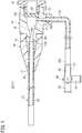
- FIG. 1is a partially-omitted schematic diagram of an embodiment of a medical tube (catheter).
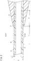
- FIG. 2is a longitudinal sectional view including a main catheter body of the catheter illustrated in FIG. 1 .
- FIG. 3is a longitudinal sectional view including a main catheter body according to a first modified example.
- FIG. 4is a longitudinal sectional view including a main catheter body according to a second modified example.
- FIG. 1is a partially-omitted schematic diagram of a catheter 10 included in a medical tube according to an embodiment of the invention.
- the catheter 10is a medical instrument that is inserted into a lumen in a living body such as a blood vessel.
- the catheter 10is configured as an introducer sheath 11 in the embodiment illustrated in FIG. 1 .
- the introducer sheath 11is a device used in combination with a dilator (not illustrated) to introduce a treatment catheter or the like percutaneously into the living body.
- the catheter 10may also be a different catheter than the introducer sheath 11 .
- the catheter 10may be a treatment catheter such as a balloon catheter, a guiding catheter, or the like.
- the catheter 10includes a main catheter body 12 (tube-shaped main body), a hub 14 , and a strain relief member 16 .
- the main catheter body 12is a flexible tube-shaped member (i.e., an elongated member possessing flexibility) and is also referred to as a shaft.
- the main catheter body 12is also referred to as a sheath tube.
- the main catheter body 12includes a lumen 13 that is open at a distal end and open at a proximal end of the main catheter body 12 .
- a length of the main catheter body 12varies according to the type (intended use) of the catheter 10 .
- the lengthis in a range of about 20 to 800 mm.
- Examples of a material used to make the main catheter body 12include polyvinyl chloride-based resin, a urethane resin such as polyurethane, an olefin-based resin such as polyethylene, polyamide, and a synthetic resin such as ethylene-vinyl acetate copolymer, silicone rubber, and latex rubber.
- the hub 14is a member that includes a lumen 15 connected to a proximal portion 12 A of the main catheter body 12 to communicate with the lumen 13 of the main catheter body 12 .
- the hub 14includes a protruding portion 19 which possesses a reduced outer diameter relative to a body portion 18 of the hub 14 .
- the protruding portion 19is protrudes in a distal end direction at a distal end of the hub 14 (i.e., protrudes distally at the distal end of the hub 14 ).
- the proximal portion 12 A of the main catheter body 12is inserted into and fixed to an inner peripheral portion at the distal end of the protruding portion 19 .
- Examples of a material used to make the hub 14include a rigid resin such as polypropylene, ABS, and polycarbonate.
- the hub 14includes a valve body 20 inside of the hub 14 .
- the valve body 20is for preventing liquid from leaking from the inside of the hub 14 .
- a hollow fixing member 21is screwed into a proximal portion of the hub 14 , and the valve body 20 is fixed inside the hub 14 when the valve body 20 is interposed between a distal end surface of the fixing member 21 and a step portion 14 a formed inside the hub 14 (i.e., a proximal surface of the valve body 20 contacts and is held in place by the distal end surface of the fixing member 21 and a distal surface of the valve body 20 contacts and is held is place against the step portion 14 a of the hub 14 ).
- the fixing of the fixing member 21 to the proximal portion of the hub 14is not restricted to screwing.
- Another structure capable of interposing (holding) the valve body 20 between the hub 14 and the fixing member 21may be used.
- the fixing member 21may be bonded or heat-welded to the hub 14 such that the valve body 20 is interposed between the hub 14 and the fixing member 21 .
- the valve body 20may be provided in a connector member connectable to a proximal end of the hub 14 instead of providing the valve body 20 directly in the hub 14 .
- the valve body 20possesses an elastic material (for example, silicone rubber).
- a slit(not illustrated), into which a dilator or another catheter can be inserted, is formed in the valve body 20 .
- the valve body 20may prevent a body fluid (blood or the like) flowing in the lumen 15 of the hub 14 through the main catheter body 12 from leaking out when the dilator (or the like) is inserted into the slit.
- a flexible side tube 22is connected to a side portion of the hub 14 .
- one end of the side tube 22is connected to a side port 23 extruding outward from the side portion of the hub 14 (i.e., the side port 23 extends radially outward from an outer circumferential surface of the hub 14 ).
- a lumen of the side tube 22communicates with the lumen 15 of the hub 14 through a side hole 14 b provided in the hub 14 .
- a three-way stopcock 24is provided at an end portion 22 b of the side tube 22 on the opposite side from an end portion 22 a connected to the hub 14 (i.e., connected to the side port 23 of the hub 14 ).
- the three-way stopcock 24may include, for example, a port 25 for discharging air, a port 26 for chemical injection to which a syringe, or the like (not illustrated) is connected, a port 27 connected to the end portion 22 b of the side tube 22 , and a cock 28 for switching communication states of the ports 25 , 26 , and 27 .
- the port 25 and the port 26are not restricted to uses for discharging air and chemical injection and may be used for other purposes.
- the strain relief member 16has a function of preventing or suppressing a kink (bending) at a proximal side or proximal portion of the main catheter body 12 (specifically, an interlock portion of the main catheter body 12 and the hub 14 and a region around the interlock portion). As illustrated in FIG. 1 , the strain relief member 16 is a hollow member having flexibility which is supported at a distal portion of the hub 14 (protruding portion 19 ) and surrounds a predetermined range of the proximal side of the main catheter body 12 .
- the strain relief member 16possesses a relatively large outer diameter at a proximal end portion and a relatively small outer diameter at a distal end portion.
- the outer diameter of the strain relief member 16gradually decreases toward the distal end (i.e., at least a portion of the strain relief member 16 is tapered).
- a wall thickness of the strain relief member 16decreases toward the distal side.
- a proximal portion of the strain relief member 16is fit onto the protruding portion 19 provided at the distal end of the hub 14 . In this way, the strain relief member 16 is supported by the distal portion of the hub 14 .
- a bulge portion 19 a annularly extending in a circumferential direction (i.e., extending radially outward)is formed on an outer peripheral surface of the protruding portion 19 in FIG. 1 .
- the strain relief member 16is thus prevented from falling off of (i.e., separating from) the protruding portion 19 when the bulge portion 19 a is engaged with an annular depression 16 a formed on an inner peripheral surface of the proximal portion of the strain relief member 16 .
- Examples of a material used to make the strain relief member 16include a thermoplastic resin such as styrene resin, olefin resin, and polyester resin.
- the main catheter body 12includes a flexible portion 30 (i.e., a less rigid or softer portion) whose flexibility for bending is increased compared to front and rear parts of the catheter main body 12 (i.e., compared to portions of the catheter main body 12 that are distal and proximal of the flexible portion 30 ) by forming at least one groove 32 (i.e., a recess or trench) extending in the circumferential direction in an outer circumferential portion over a predetermined range.
- a flexible portion 30i.e., a less rigid or softer portion
- at least one groove 32i.e., a recess or trench
- the predetermined range of the main catheter body 12extends from a portion of the main catheter body 12 that is distal to a most distal portion 17 (i.e., a distal-most portion) of the strain relief member 16 to another portion of the main catheter body 12 that is proximal to the most distal portion 17 (i.e., proximal to the distal-most portion 17 ).
- the groove 32is a portion indented by a depth H with respect to an outer diameter D (reference outer diameter) of the main catheter body 12 . Therefore, a wall thickness of a portion of the main catheter body 12 in which the groove 32 is formed is thinner than a wall thickness T of a portion other than the flexible portion 30 by the depth H of the groove 32 .
- the flexible portion 30has higher flexibility than that of the front and rear parts of the softness portion 30 in the main catheter body 12 because of the groove 32 .
- the groove 32 extending in the circumferential directionis a helical groove 33 .
- the helical groove 33may be a single helix or a multiple helix such as a double helix.
- the helical groove 33may be a groove which is not continuous from a distal end to a proximal end of the flexible portion 30 and may be intermittent (interrupted) at one or more places in the middle.
- the groove 32may be an annular groove instead of the helical groove 33 , and a plurality of (multiple) annular grooves may be formed in the outer circumferential portion of the main catheter body 12 at intervals along an axial direction.
- the depth H of the groove 32may be 5 to 50% with respect to the thickness T of the wall that forms the main catheter body 12 .
- the depth H of the groove 32more preferably may be 20 to 40% relative to the thickness of the wall T.
- the depth Hmay be set to about 30 to 100 ⁇ m.
- the distance L 1 from the most distal portion 17 of the strain relief member 16 to a most distal portion (i.e., distal-most portion) of the flexible portion 30 (i.e., the distal-most portion of the groove 32 )may be 5 to 50 mm, preferably 10 to 30 mm.
- the distance L 2 from the most distal portion 17 of the strain relief member 16 to the most proximal portion of the flexible portion 30 (i.e., the proximal-most portion of the groove 32 )may be 5 to 50 mm, preferably 10 to 30 mm.
- the helical groove 33may be formed by helicoidally winding a linear member (wire or the like) around an outer peripheral surface of a tube-shaped compact (which is supported by a spindle and has the outer diameter D (the main catheter body 12 before the flexible portion 30 is formed)) along a predetermined range in an axial direction, heating the linear member, and then removing the linear member.
- the groove 32may be formed by helicoidally or annularly scraping the outer peripheral surface of the compact instead of using the above-described method using the linear member.
- the main catheter body 12 including the groove 32may be manufactured by injection molding using an injection molding tool that possesses a shape corresponding to the groove 32 in advance.
- the catheter 10is configured as an introducer sheath 11 .
- the introducer sheath 11is combined with a dilator (not illustrated).
- an assemblyin which the dilator is positioned in the introducer sheath 11 punctures a blood vessel of a patient such that a distal end of the introducer sheath 11 secures or punctures the blood vessel.
- the main catheter body 12is further inserted into the blood vessel and inserted up to a portion around the most distal portion 17 of the strain relief member 16 .
- the dilatoris then pulled out of the introducer sheath 11 .
- a length of the main catheter body 12 inserted into or positioned in the blood vesselis set to a predetermined length.
- another devicesuch as a treatment catheter (balloon catheter or the like) or a guiding catheter is introduced through or into the introducer sheath 11 while being led by a guide wire (not illustrated) inside the blood vessel.
- the deviceis advanced up to a predetermined region inside the living body, and treatment is performed.
- the proximal-side portion of the main catheter body 12(the interlock portion of the main catheter body 12 and the hub 14 ) is exposed to the outside of the body during a surgery.
- bending stressacts on the proximal-side portion of the main catheter body 12 .
- the strain relief member 16is thus provided to suppress the occurrence of a kink (i.e., kinking) in the proximal-side portion of the main catheter body 12 due to bending stress at this time.
- a kinkmay occur when the amount of change of the main catheter body 12 bending is greater than or equal to a certain amount.
- bending rigiditygreatly varies, and stress is easily concentrated.
- a kinkmore easily occurs in this location.
- the catheter 10thus includes the flexible portion 30 , the flexibility of which is increased by the groove 32 , in a front-rear range including the most distal portion 17 of the strain relief member 16 in the main catheter body 12 (i.e., the distal-most end of the flexible portion 30 is distal to the distal most portion 17 of the strain relief 16 and the proximal-most end of the flexible portion 30 is proximal to the distal-most portion 17 of the strain relief 16 ).
- the flexible portion 30has higher flexibility than that of the portion of the main catheter body 12 in which the groove 32 is not provided. Specifically, the flexible portion 30 is more flexible than a portion of the catheter main body 12 distal to the flexible portion and a portion of the catheter main body 12 proximal to the flexible portion 30 .
- the main catheter body 12 having the flexible portion 30is more flexible with respect to bending when compared at the same outer diameter D (i.e., a portion of the main catheter body 12 other than the flexible portion 30 that has outer diameter D is less flexible or more rigid than the flexible portion 30 having the same outer diameter D).
- the amount of change of bending at which a kink may occuris larger in the main catheter body 12 having the flexible portion 30 than in a conventional main catheter body not having the flexible portion 30 .
- a more flexible portion of the catheter 10(that is, a less rigid portion than another portion in the axial direction) is provided in a particular region of the proximal portion of the main catheter body 12 and is allowed to be easily bent.
- the more flexible portion of the catheter 10thereby suppresses stress concentration due to bending and inhibits the occurrence of a kink. Therefore, according to the catheter 10 , kink resistance of the main catheter body 12 may be increased while reducing the wall thickness of the main catheter body 12 .
- the groove 32which is provided in the outer circumferential portion of the main catheter body 12 and extends in the circumferential direction, is may be a helical groove 33 as illustrated in FIG. 2 .
- the helical groove 33is easily formed by winding a linear member around the outer circumferential portion of the tube-shaped compact, it is possible to easily manufacture the main catheter body 12 having the flexible portion 30 over the predetermined range in the axial direction.
- the main catheter body 12When the introducer sheath 11 is indwelled inside the blood vessel, the main catheter body 12 is inserted into the blood vessel up to a portion around the most distal portion 17 of the strain relief member 16 . A portion around the strain relief member 16 of the main catheter body 12 may thus come into contact with a skin or a blood vessel wall. The degree of curvature locally increases relatively easily in the portion. Thus, a kink may easily occur in this portion. For this reason, the medical tube disclosed here is capable of suppressing a kink in the proximal-side portion of the main catheter body 12 and is thus suitable when used for the introducer sheath 11 .
- a plurality of sub-regions 30 A and 30 B having different groove pitchesmay be provided in a flexible portion 40 of a main catheter body 12 a according to a first modified example illustrated in FIG. 3 .
- the sub-region 30 A on a distal side in the embodiment illustrated in FIG. 3is more flexible than where the sub-regions 30 A and 30 B are adjacent to each other (and thus the sub-region 30 A is also more flexible than the sub-region 30 B on the proximal side).
- At least one boundary portion C between the sub-regions 30 A and 30 Bis positioned on the distal side from a most distal portion 17 of a strain relief member 16 (i.e., distal to the distal-most end of the strain relief member 16 ).
- the flexible portion 30includes the first sub-region 30 A, in which a groove 32 A is formed at a relatively small pitch P 1 , and the second sub-region 30 B, in which a groove 32 B is formed at a relatively large pitch P 2 . Therefore, the first sub-region 30 A has higher flexibility with respect to bending than the flexibility of the second sub-region 30 B.
- the range indicated by A in FIG. 3refers to the first sub-region 30 A and a range indicated by B refers to the second sub-region 30 B in FIG. 3 .
- flexibility obtained by applying rigidity of the strain relief member 16 to the main catheter body 12 ais higher in a portion from a boundary portion C between the first sub-region 30 A and the second sub-region 30 B to the most distal portion 17 of the strain relief member 16 than in a portion from the most distal portion 17 of the strain relief member 16 to a most proximal portion of the second sub-region 30 B.
- Each of the grooves 32 A and 32 B in the first sub-region 30 A and the second sub-region 30 B of the embodiment illustrated in FIG. 3is a helical groove.
- Each of the grooves 32 A and 32 Bmay correspond to a plurality of annular grooves formed at intervals in an axial direction in place of the helical groove.
- the groove 32 A of the first sub-region 30 A and the groove 32 B of the second sub-region 30 Bmay communicate with each other or may be independent from each other (i.e., do not communicate with one another).
- Flexibility of the embodiment illustrated in FIG. 3increases in stages toward the distal side in a front-rear region including the most distal portion 17 of the strain relief member 16 because the flexible portion 40 includes a plurality of sub-regions 30 A and 30 B having different groove pitches.
- the configuration of the embodiment illustrated in FIG. 3makes it possible to more effectively suppress the occurrence of a kink in the main catheter body 12 a .
- three or more sub-regions having different groove pitchesmay be provided in the main catheter body 12 a.
- FIG. 4illustrates a second modified example of an embodiment of the medical tube disclosed here.
- the flexible portion 42 of a main catheter body 12 b according to the embodiment illustrated in FIG. 4includes a first sub-region 30 A that may have higher flexibility with respect to bending than that of a second sub-region 30 B.
- the higher flexibility of the first sub-region 30 Amay be obtained by setting a width W 1 of a groove 32 A of the first sub-region 30 A to be larger than a width W 2 of a groove 32 B of the second sub-region 30 B.
- the same effect as that of a configuration of FIG. 3is obtained by a configuration of FIG. 4 .
- three or more sub-regions having different groove widthsmay be provided in the main catheter body 12 b.
Landscapes
- Health & Medical Sciences (AREA)
- Life Sciences & Earth Sciences (AREA)
- Heart & Thoracic Surgery (AREA)
- Biomedical Technology (AREA)
- Engineering & Computer Science (AREA)
- Anesthesiology (AREA)
- Pulmonology (AREA)
- Hematology (AREA)
- Animal Behavior & Ethology (AREA)
- General Health & Medical Sciences (AREA)
- Public Health (AREA)
- Veterinary Medicine (AREA)
- Biophysics (AREA)
- Media Introduction/Drainage Providing Device (AREA)
Abstract
Description
Claims (19)
Applications Claiming Priority (3)
| Application Number | Priority Date | Filing Date | Title |
|---|---|---|---|
| JP2014051405 | 2014-03-14 | ||
| JP2014-051405 | 2014-03-14 | ||
| PCT/JP2015/054918WO2015137098A1 (en) | 2014-03-14 | 2015-02-23 | Medical tube |
Related Parent Applications (1)
| Application Number | Title | Priority Date | Filing Date |
|---|---|---|---|
| PCT/JP2015/054918ContinuationWO2015137098A1 (en) | 2014-03-14 | 2015-02-23 | Medical tube |
Publications (2)
| Publication Number | Publication Date |
|---|---|
| US20160375222A1 US20160375222A1 (en) | 2016-12-29 |
| US10835712B2true US10835712B2 (en) | 2020-11-17 |
Family
ID=54071547
Family Applications (1)
| Application Number | Title | Priority Date | Filing Date |
|---|---|---|---|
| US15/263,973Active2035-10-09US10835712B2 (en) | 2014-03-14 | 2016-09-13 | Medical tube |
Country Status (4)
| Country | Link |
|---|---|
| US (1) | US10835712B2 (en) |
| EP (1) | EP3117863B1 (en) |
| JP (1) | JP6434495B2 (en) |
| WO (1) | WO2015137098A1 (en) |
Cited By (20)
| Publication number | Priority date | Publication date | Assignee | Title |
|---|---|---|---|---|
| US11617861B2 (en) | 2014-06-17 | 2023-04-04 | St. Jude Medical, Cardiology Division, Inc. | Triple coil catheter support |
| US11642064B2 (en) | 2015-10-21 | 2023-05-09 | St. Jude Medical, Cardiology Division, Inc. | High density electrode mapping catheter |
| US11642063B2 (en) | 2018-08-23 | 2023-05-09 | St. Jude Medical, Cardiology Division, Inc. | Curved high density electrode mapping catheter |
| US11647935B2 (en) | 2017-07-24 | 2023-05-16 | St. Jude Medical, Cardiology Division, Inc. | Masked ring electrodes |
| US11672947B2 (en) | 2017-11-28 | 2023-06-13 | St. Jude Medical, Cardiology Division, Inc. | Lumen management catheter |
| US11707229B2 (en) | 2015-05-08 | 2023-07-25 | St Jude Medical International Holding S.À R.L. | Integrated sensors for medical devices and method of making integrated sensors for medical devices |
| US11786705B2 (en) | 2016-10-24 | 2023-10-17 | St. Jude Medical, Cardiology Division, Inc. | Catheter insertion devices |
| US11826172B2 (en) | 2014-05-06 | 2023-11-28 | St. Jude Medical, Cardiology Division, Inc. | Electrode support structure assembly |
| US11844910B2 (en) | 2014-06-05 | 2023-12-19 | St. Jude Medical, Cardiology Division, Inc. | Deflectable catheter shaft section |
| US11918762B2 (en) | 2018-10-03 | 2024-03-05 | St. Jude Medical, Cardiology Division, Inc. | Reduced actuation force electrophysiology catheter handle |
| US12011549B2 (en) | 2017-01-19 | 2024-06-18 | St. Jude Medical, Cardiology Division, Inc. | Sheath visualization |
| US12036027B2 (en) | 2016-10-28 | 2024-07-16 | St. Jude Medical, Cardiology Division, Inc. | Flexible high-density mapping catheter |
| US12048545B2 (en) | 2014-10-27 | 2024-07-30 | St. Jude Medical, Cardiology Division, Inc. | Apparatus and method for connecting elements in medical devices |
| US12076079B2 (en) | 2016-05-03 | 2024-09-03 | St. Jude Medical, Cardiology Division, Inc. | Irrigated high density electrode catheter |
| US12082936B2 (en) | 2018-09-27 | 2024-09-10 | St. Jude Medical, Cardiology Division, Inc. | Uniform mapping balloon |
| US12121357B2 (en) | 2015-10-21 | 2024-10-22 | St. Jude Medical, Cardiology Division, Inc. | High density electrode mapping catheter |
| US12156979B2 (en) | 2018-05-21 | 2024-12-03 | St. Jude Medical, Cardiology Division, Inc. | Deflectable catheter shaft with pullwire anchor feature |
| US12263014B2 (en) | 2020-08-18 | 2025-04-01 | St. Jude Medical, Cardiology Division, Inc. | High-density electrode catheters with magnetic position tracking |
| US12376901B2 (en) | 2018-05-21 | 2025-08-05 | St. Jude Medical, Cardiology Division, Inc. | Radio-frequency ablation and direct current electroporation catheters |
| US12383333B2 (en) | 2015-01-28 | 2025-08-12 | St. Jude Medical, Cardiology Division, Inc. | Thermal mapping catheter |
Families Citing this family (17)
| Publication number | Priority date | Publication date | Assignee | Title |
|---|---|---|---|---|
| US9750928B2 (en) | 2013-02-13 | 2017-09-05 | Becton, Dickinson And Company | Blood control IV catheter with stationary septum activator |
| US10376686B2 (en) | 2014-04-23 | 2019-08-13 | Becton, Dickinson And Company | Antimicrobial caps for medical connectors |
| US9789279B2 (en) | 2014-04-23 | 2017-10-17 | Becton, Dickinson And Company | Antimicrobial obturator for use with vascular access devices |
| US10232088B2 (en) | 2014-07-08 | 2019-03-19 | Becton, Dickinson And Company | Antimicrobial coating forming kink resistant feature on a vascular access device |
| US10463840B2 (en)* | 2015-10-28 | 2019-11-05 | Becton, Dickinson And Company | Compliant catheter adapter having self-slitting needle |
| US10493244B2 (en) | 2015-10-28 | 2019-12-03 | Becton, Dickinson And Company | Extension tubing strain relief |
| EP3266486B1 (en)* | 2016-07-06 | 2019-01-30 | Abiomed Europe GmbH | Introducer sheath for vascular access |
| AU2017373953B2 (en) | 2016-12-08 | 2023-05-11 | Abiomed, Inc. | Overmold technique for peel-away introducer design |
| JP6940591B2 (en)* | 2017-03-30 | 2021-09-29 | テルモ株式会社 | Oxygen measurement device and oxygen measurement system |
| JP6975778B2 (en)* | 2017-04-28 | 2021-12-01 | テルモ株式会社 | Air removal mechanism and introducer sheath |
| JP2019017875A (en)* | 2017-07-20 | 2019-02-07 | テルモ株式会社 | Introducer sheath and introducer |
| KR102452113B1 (en) | 2017-11-06 | 2022-10-07 | 아비오메드, 인크. | Separable hemostatic valve |
| CN111465420B (en)* | 2017-12-15 | 2023-04-18 | 佩尔福兹有限公司 | Improved catheter and apparatus and system incorporating same |
| ES2991910T3 (en) | 2018-05-16 | 2024-12-05 | Abiomed Inc | Removable cover set |
| US10946167B2 (en)* | 2018-06-14 | 2021-03-16 | Covidien Lp | Catheter hub and strain relief |
| JP7312556B2 (en)* | 2019-01-25 | 2023-07-21 | テルモ株式会社 | catheter |
| JPWO2021192994A1 (en)* | 2020-03-27 | 2021-09-30 |
Citations (14)
| Publication number | Priority date | Publication date | Assignee | Title |
|---|---|---|---|---|
| JPS5914601U (en) | 1982-07-21 | 1984-01-28 | 旭光学工業株式会社 | Endoscope channel tube |
| US5466230A (en) | 1994-06-09 | 1995-11-14 | Cordis Corporation | Catheter sheath introducer with strain relief |
| JPH0871161A (en) | 1994-09-12 | 1996-03-19 | Terumo Corp | Introducer |
| JPH08215312A (en) | 1995-02-09 | 1996-08-27 | Terumo Corp | Balloon catheter |
| US5897537A (en)* | 1994-02-14 | 1999-04-27 | Scimed Life Systems, Inc. | Guide catheter having a plurality of filled distal grooves |
| JP2000254235A (en) | 1999-03-10 | 2000-09-19 | Terumo Corp | Medical tube and its manufacture |
| US20020143291A1 (en) | 2001-03-30 | 2002-10-03 | Slater Renee C. | Steerable drug delivery device |
| US20030004540A1 (en)* | 2001-07-02 | 2003-01-02 | Rubicon Medical, Inc. | Methods, systems, and devices for deploying an embolic protection filter |
| US7001369B2 (en) | 2003-03-27 | 2006-02-21 | Scimed Life Systems, Inc. | Medical device |
| US20060264904A1 (en)* | 2005-05-09 | 2006-11-23 | Kerby Walter L | Medical device |
| US20100198160A1 (en) | 2006-06-28 | 2010-08-05 | Abbott Vascular Inc. | Expandable Introducer Sheaths and Methods for Manufacture and Use |
| US20120071833A1 (en) | 2007-03-02 | 2012-03-22 | Hill Roger J | Implantable catheter or lead anchor for implantable medical device system and method of use |
| JP2013022367A (en) | 2011-07-25 | 2013-02-04 | Goodman Co Ltd | Catheter and method of manufacturing the same |
| US8409114B2 (en)* | 2007-08-02 | 2013-04-02 | Boston Scientific Scimed, Inc. | Composite elongate medical device including distal tubular member |
Family Cites Families (2)
| Publication number | Priority date | Publication date | Assignee | Title |
|---|---|---|---|---|
| US20080188793A1 (en)* | 2007-02-06 | 2008-08-07 | Possis Medical, Inc. | Miniature flexible thrombectomy catheter |
| US9808595B2 (en)* | 2007-08-07 | 2017-11-07 | Boston Scientific Scimed, Inc | Microfabricated catheter with improved bonding structure |
- 2015
- 2015-02-23EPEP15760901.7Apatent/EP3117863B1/enactiveActive
- 2015-02-23JPJP2016507427Apatent/JP6434495B2/enactiveActive
- 2015-02-23WOPCT/JP2015/054918patent/WO2015137098A1/enactiveIP Right Grant
- 2016
- 2016-09-13USUS15/263,973patent/US10835712B2/enactiveActive
Patent Citations (14)
| Publication number | Priority date | Publication date | Assignee | Title |
|---|---|---|---|---|
| JPS5914601U (en) | 1982-07-21 | 1984-01-28 | 旭光学工業株式会社 | Endoscope channel tube |
| US5897537A (en)* | 1994-02-14 | 1999-04-27 | Scimed Life Systems, Inc. | Guide catheter having a plurality of filled distal grooves |
| US5466230A (en) | 1994-06-09 | 1995-11-14 | Cordis Corporation | Catheter sheath introducer with strain relief |
| JPH0871161A (en) | 1994-09-12 | 1996-03-19 | Terumo Corp | Introducer |
| JPH08215312A (en) | 1995-02-09 | 1996-08-27 | Terumo Corp | Balloon catheter |
| JP2000254235A (en) | 1999-03-10 | 2000-09-19 | Terumo Corp | Medical tube and its manufacture |
| US20020143291A1 (en) | 2001-03-30 | 2002-10-03 | Slater Renee C. | Steerable drug delivery device |
| US20030004540A1 (en)* | 2001-07-02 | 2003-01-02 | Rubicon Medical, Inc. | Methods, systems, and devices for deploying an embolic protection filter |
| US7001369B2 (en) | 2003-03-27 | 2006-02-21 | Scimed Life Systems, Inc. | Medical device |
| US20060264904A1 (en)* | 2005-05-09 | 2006-11-23 | Kerby Walter L | Medical device |
| US20100198160A1 (en) | 2006-06-28 | 2010-08-05 | Abbott Vascular Inc. | Expandable Introducer Sheaths and Methods for Manufacture and Use |
| US20120071833A1 (en) | 2007-03-02 | 2012-03-22 | Hill Roger J | Implantable catheter or lead anchor for implantable medical device system and method of use |
| US8409114B2 (en)* | 2007-08-02 | 2013-04-02 | Boston Scientific Scimed, Inc. | Composite elongate medical device including distal tubular member |
| JP2013022367A (en) | 2011-07-25 | 2013-02-04 | Goodman Co Ltd | Catheter and method of manufacturing the same |
Non-Patent Citations (3)
| Title |
|---|
| International Search Report (PCT/ISA/210) issued on May 26, 2015, by the Japanese Patent Office as the International Searching Authority for International Application No. PCT/JP2015/054918. |
| The extended European Search Report dated Sep. 21, 2017, by the European Patent Office in corresponding European Patent Application No. 15760901.7-1501. (8 pages). |
| Written Opinion (PCT/ISA/237) dated May 26, 2015, by the Japanese Patent Office as the International Searching Authority for International Application No. PCT/JP2015/054918. |
Cited By (22)
| Publication number | Priority date | Publication date | Assignee | Title |
|---|---|---|---|---|
| US11826172B2 (en) | 2014-05-06 | 2023-11-28 | St. Jude Medical, Cardiology Division, Inc. | Electrode support structure assembly |
| US11844910B2 (en) | 2014-06-05 | 2023-12-19 | St. Jude Medical, Cardiology Division, Inc. | Deflectable catheter shaft section |
| US11617861B2 (en) | 2014-06-17 | 2023-04-04 | St. Jude Medical, Cardiology Division, Inc. | Triple coil catheter support |
| US12048545B2 (en) | 2014-10-27 | 2024-07-30 | St. Jude Medical, Cardiology Division, Inc. | Apparatus and method for connecting elements in medical devices |
| US12383333B2 (en) | 2015-01-28 | 2025-08-12 | St. Jude Medical, Cardiology Division, Inc. | Thermal mapping catheter |
| US11707229B2 (en) | 2015-05-08 | 2023-07-25 | St Jude Medical International Holding S.À R.L. | Integrated sensors for medical devices and method of making integrated sensors for medical devices |
| US11642064B2 (en) | 2015-10-21 | 2023-05-09 | St. Jude Medical, Cardiology Division, Inc. | High density electrode mapping catheter |
| US12121357B2 (en) | 2015-10-21 | 2024-10-22 | St. Jude Medical, Cardiology Division, Inc. | High density electrode mapping catheter |
| US12076079B2 (en) | 2016-05-03 | 2024-09-03 | St. Jude Medical, Cardiology Division, Inc. | Irrigated high density electrode catheter |
| US11786705B2 (en) | 2016-10-24 | 2023-10-17 | St. Jude Medical, Cardiology Division, Inc. | Catheter insertion devices |
| US12036027B2 (en) | 2016-10-28 | 2024-07-16 | St. Jude Medical, Cardiology Division, Inc. | Flexible high-density mapping catheter |
| US12011549B2 (en) | 2017-01-19 | 2024-06-18 | St. Jude Medical, Cardiology Division, Inc. | Sheath visualization |
| US11647935B2 (en) | 2017-07-24 | 2023-05-16 | St. Jude Medical, Cardiology Division, Inc. | Masked ring electrodes |
| US12138059B2 (en) | 2017-07-24 | 2024-11-12 | St. Jude Medical, Cardiology Division, Inc. | Masked ring electrodes |
| US11813410B2 (en) | 2017-11-28 | 2023-11-14 | St. Jude Medical, Cardiology Division, Inc. | Controllable expandable catheter |
| US11672947B2 (en) | 2017-11-28 | 2023-06-13 | St. Jude Medical, Cardiology Division, Inc. | Lumen management catheter |
| US12376901B2 (en) | 2018-05-21 | 2025-08-05 | St. Jude Medical, Cardiology Division, Inc. | Radio-frequency ablation and direct current electroporation catheters |
| US12156979B2 (en) | 2018-05-21 | 2024-12-03 | St. Jude Medical, Cardiology Division, Inc. | Deflectable catheter shaft with pullwire anchor feature |
| US11642063B2 (en) | 2018-08-23 | 2023-05-09 | St. Jude Medical, Cardiology Division, Inc. | Curved high density electrode mapping catheter |
| US12082936B2 (en) | 2018-09-27 | 2024-09-10 | St. Jude Medical, Cardiology Division, Inc. | Uniform mapping balloon |
| US11918762B2 (en) | 2018-10-03 | 2024-03-05 | St. Jude Medical, Cardiology Division, Inc. | Reduced actuation force electrophysiology catheter handle |
| US12263014B2 (en) | 2020-08-18 | 2025-04-01 | St. Jude Medical, Cardiology Division, Inc. | High-density electrode catheters with magnetic position tracking |
Also Published As
| Publication number | Publication date |
|---|---|
| EP3117863A4 (en) | 2017-10-25 |
| EP3117863A1 (en) | 2017-01-18 |
| EP3117863B1 (en) | 2025-04-16 |
| WO2015137098A1 (en) | 2015-09-17 |
| JP6434495B2 (en) | 2018-12-05 |
| US20160375222A1 (en) | 2016-12-29 |
| JPWO2015137098A1 (en) | 2017-04-06 |
Similar Documents
| Publication | Publication Date | Title |
|---|---|---|
| US10835712B2 (en) | Medical tube | |
| EP3115076B1 (en) | Catheter | |
| EP2217314B1 (en) | Drainage catheter | |
| CN106620994B (en) | Catheter adapter with distal inner diameter curvature providing kink resistance | |
| US11904115B2 (en) | Catheter assembly | |
| US20120041419A1 (en) | Trimmable catheter including distal portion stability features | |
| US9320873B2 (en) | Introducer sheath and introducer assembly | |
| JPWO2018043427A1 (en) | Introducer sheath | |
| US10799684B2 (en) | Introducer sheath and introducer assembly | |
| US20240181236A1 (en) | Hemostasis seal with low pass-through friction force | |
| US9592368B2 (en) | Introducer sheath and method for using the same | |
| US20170197065A1 (en) | Medical elongated body | |
| US20210085920A1 (en) | Strain relief and methods of use thereof | |
| US20210220618A1 (en) | Catheter assembly | |
| JP7108396B2 (en) | catheter and manifold | |
| JP2005329063A (en) | Dilator | |
| JP2005329062A (en) | Introducer sheath | |
| US20240358508A1 (en) | Peelable advancer for delivery system | |
| EP4472710A1 (en) | Central venous catheter | |
| JP2024168893A (en) | Introducer sheath | |
| WO2025188657A1 (en) | Extendable introducer tip | |
| JP2019176978A (en) | Medical long body, medical device, and medical method | |
| JP2019058529A (en) | Introducer sheath and introducer |
Legal Events
| Date | Code | Title | Description |
|---|---|---|---|
| AS | Assignment | Owner name:TERUMO KABUSHIKI KAISHA, JAPAN Free format text:ASSIGNMENT OF ASSIGNORS INTEREST;ASSIGNOR:WADA, SATOSHI;REEL/FRAME:039719/0801 Effective date:20160906 | |
| STPP | Information on status: patent application and granting procedure in general | Free format text:RESPONSE TO NON-FINAL OFFICE ACTION ENTERED AND FORWARDED TO EXAMINER | |
| STPP | Information on status: patent application and granting procedure in general | Free format text:FINAL REJECTION MAILED | |
| STPP | Information on status: patent application and granting procedure in general | Free format text:RESPONSE AFTER FINAL ACTION FORWARDED TO EXAMINER | |
| STPP | Information on status: patent application and granting procedure in general | Free format text:ADVISORY ACTION MAILED | |
| STPP | Information on status: patent application and granting procedure in general | Free format text:DOCKETED NEW CASE - READY FOR EXAMINATION | |
| STPP | Information on status: patent application and granting procedure in general | Free format text:NON FINAL ACTION MAILED | |
| STPP | Information on status: patent application and granting procedure in general | Free format text:RESPONSE TO NON-FINAL OFFICE ACTION ENTERED AND FORWARDED TO EXAMINER | |
| STPP | Information on status: patent application and granting procedure in general | Free format text:NOTICE OF ALLOWANCE MAILED -- APPLICATION RECEIVED IN OFFICE OF PUBLICATIONS | |
| STPP | Information on status: patent application and granting procedure in general | Free format text:PUBLICATIONS -- ISSUE FEE PAYMENT RECEIVED | |
| STPP | Information on status: patent application and granting procedure in general | Free format text:PUBLICATIONS -- ISSUE FEE PAYMENT VERIFIED | |
| STCF | Information on status: patent grant | Free format text:PATENTED CASE | |
| MAFP | Maintenance fee payment | Free format text:PAYMENT OF MAINTENANCE FEE, 4TH YEAR, LARGE ENTITY (ORIGINAL EVENT CODE: M1551); ENTITY STATUS OF PATENT OWNER: LARGE ENTITY Year of fee payment:4 |