US10835655B2 - Mobility-enhancing blood pump system - Google Patents
Mobility-enhancing blood pump systemDownload PDFInfo
- Publication number
- US10835655B2 US10835655B2US16/026,947US201816026947AUS10835655B2US 10835655 B2US10835655 B2US 10835655B2US 201816026947 AUS201816026947 AUS 201816026947AUS 10835655 B2US10835655 B2US 10835655B2
- Authority
- US
- United States
- Prior art keywords
- blood pump
- implantable
- pump
- power
- external
- Prior art date
- Legal status (The legal status is an assumption and is not a legal conclusion. Google has not performed a legal analysis and makes no representation as to the accuracy of the status listed.)
- Active, expires
Links
- 239000008280bloodSubstances0.000titleclaimsabstractdescription121
- 210000004369bloodAnatomy0.000titleclaimsabstractdescription121
- 238000000034methodMethods0.000claimsdescription25
- 239000004020conductorSubstances0.000claimsdescription15
- 230000000694effectsEffects0.000claimsdescription14
- 238000012806monitoring deviceMethods0.000claimsdescription12
- 210000001015abdomenAnatomy0.000claimsdescription11
- 230000005540biological transmissionEffects0.000claimsdescription8
- 230000006378damageEffects0.000claimsdescription6
- 230000008859changeEffects0.000claimsdescription5
- 230000017531blood circulationEffects0.000claimsdescription3
- 238000012544monitoring processMethods0.000claims3
- 238000005086pumpingMethods0.000abstractdescription8
- 239000013589supplementSubstances0.000abstractdescription5
- 230000001502supplementing effectEffects0.000abstractdescription2
- 230000002861ventricularEffects0.000description34
- 238000012546transferMethods0.000description30
- 230000006870functionEffects0.000description21
- 208000015181infectious diseaseDiseases0.000description16
- 238000004891communicationMethods0.000description14
- 210000001519tissueAnatomy0.000description11
- 210000000038chestAnatomy0.000description10
- 230000003247decreasing effectEffects0.000description9
- 239000012530fluidSubstances0.000description8
- 229910052751metalInorganic materials0.000description6
- 239000002184metalSubstances0.000description6
- 230000005611electricityEffects0.000description4
- 239000007943implantSubstances0.000description4
- XLYOFNOQVPJJNP-UHFFFAOYSA-NwaterSubstancesOXLYOFNOQVPJJNP-UHFFFAOYSA-N0.000description4
- 230000000712assemblyEffects0.000description3
- 238000000429assemblyMethods0.000description3
- 230000000977initiatory effectEffects0.000description3
- 210000005240left ventricleAnatomy0.000description3
- 239000007788liquidSubstances0.000description3
- 239000000463materialSubstances0.000description3
- 229920000642polymerPolymers0.000description3
- 230000009182swimmingEffects0.000description3
- 206010019280Heart failuresDiseases0.000description2
- UFHFLCQGNIYNRP-UHFFFAOYSA-NHydrogenChemical compound[H][H]UFHFLCQGNIYNRP-UHFFFAOYSA-N0.000description2
- RTAQQCXQSZGOHL-UHFFFAOYSA-NTitaniumChemical compound[Ti]RTAQQCXQSZGOHL-UHFFFAOYSA-N0.000description2
- 230000003187abdominal effectEffects0.000description2
- 230000036772blood pressureEffects0.000description2
- 238000005516engineering processMethods0.000description2
- 230000017525heat dissipationEffects0.000description2
- 238000010438heat treatmentMethods0.000description2
- 229910052739hydrogenInorganic materials0.000description2
- 239000001257hydrogenSubstances0.000description2
- 238000002513implantationMethods0.000description2
- 229920001690polydopaminePolymers0.000description2
- 230000009467reductionEffects0.000description2
- 230000011664signalingEffects0.000description2
- 238000001356surgical procedureMethods0.000description2
- 238000002560therapeutic procedureMethods0.000description2
- 239000010936titaniumSubstances0.000description2
- 229910052719titaniumInorganic materials0.000description2
- 206010007559Cardiac failure congestiveDiseases0.000description1
- 206010061598ImmunodeficiencyDiseases0.000description1
- WHXSMMKQMYFTQS-UHFFFAOYSA-NLithiumChemical compound[Li]WHXSMMKQMYFTQS-UHFFFAOYSA-N0.000description1
- HBBGRARXTFLTSG-UHFFFAOYSA-NLithium ionChemical compound[Li+]HBBGRARXTFLTSG-UHFFFAOYSA-N0.000description1
- 241000237536Mytilus edulisSpecies0.000description1
- 239000004696Poly ether ether ketoneSubstances0.000description1
- 239000004698PolyethyleneSubstances0.000description1
- 206010040047SepsisDiseases0.000description1
- 229910001069Ti alloyInorganic materials0.000description1
- 229910000883Ti6Al4VInorganic materials0.000description1
- 239000004699Ultra-high molecular weight polyethyleneSubstances0.000description1
- 208000027418Wounds and injuryDiseases0.000description1
- 238000004873anchoringMethods0.000description1
- 230000003416augmentationEffects0.000description1
- 238000003287bathingMethods0.000description1
- 230000009286beneficial effectEffects0.000description1
- JUPQTSLXMOCDHR-UHFFFAOYSA-Nbenzene-1,4-diol;bis(4-fluorophenyl)methanoneChemical compoundOC1=CC=C(O)C=C1.C1=CC(F)=CC=C1C(=O)C1=CC=C(F)C=C1JUPQTSLXMOCDHR-UHFFFAOYSA-N0.000description1
- 229920000249biocompatible polymerPolymers0.000description1
- 230000015572biosynthetic processEffects0.000description1
- 239000003990capacitorSubstances0.000description1
- 230000001756cardiomyopathic effectEffects0.000description1
- 239000000919ceramicSubstances0.000description1
- 239000000788chromium alloySubstances0.000description1
- 235000019504cigarettesNutrition0.000description1
- 239000011248coating agentSubstances0.000description1
- 238000000576coating methodMethods0.000description1
- 239000000356contaminantSubstances0.000description1
- 230000001276controlling effectEffects0.000description1
- 230000008878couplingEffects0.000description1
- 238000010168coupling processMethods0.000description1
- 238000005859coupling reactionMethods0.000description1
- 238000013461designMethods0.000description1
- 238000007599dischargingMethods0.000description1
- 238000004146energy storageMethods0.000description1
- 239000000446fuelSubstances0.000description1
- 238000010413gardeningMethods0.000description1
- 231100001261hazardousToxicity0.000description1
- 230000004217heart functionEffects0.000description1
- 230000000004hemodynamic effectEffects0.000description1
- 208000014674injuryDiseases0.000description1
- 238000009413insulationMethods0.000description1
- 229910052744lithiumInorganic materials0.000description1
- 229910001416lithium ionInorganic materials0.000description1
- 230000007774longtermEffects0.000description1
- 238000012423maintenanceMethods0.000description1
- 230000007257malfunctionEffects0.000description1
- 150000002739metalsChemical class0.000description1
- 238000012986modificationMethods0.000description1
- 230000004048modificationEffects0.000description1
- 210000003205muscleAnatomy0.000description1
- 235000020638musselNutrition0.000description1
- 208000010125myocardial infarctionDiseases0.000description1
- 230000007170pathologyEffects0.000description1
- 230000000144pharmacologic effectEffects0.000description1
- 229920002530polyetherether ketonePolymers0.000description1
- -1polyethylenePolymers0.000description1
- 229920000573polyethylenePolymers0.000description1
- 239000000047productSubstances0.000description1
- 238000011084recoveryMethods0.000description1
- 230000001105regulatory effectEffects0.000description1
- 210000005241right ventricleAnatomy0.000description1
- 238000000926separation methodMethods0.000description1
- 239000010935stainless steelSubstances0.000description1
- 229910001220stainless steelInorganic materials0.000description1
- 239000003826tabletSubstances0.000description1
- 230000001225therapeutic effectEffects0.000description1
- 238000002054transplantationMethods0.000description1
- 230000005641tunnelingEffects0.000description1
- 229920000785ultra high molecular weight polyethylenePolymers0.000description1
- 235000015041whiskyNutrition0.000description1
Images


Classifications
- A61M1/1086—
- A—HUMAN NECESSITIES
- A61—MEDICAL OR VETERINARY SCIENCE; HYGIENE
- A61M—DEVICES FOR INTRODUCING MEDIA INTO, OR ONTO, THE BODY; DEVICES FOR TRANSDUCING BODY MEDIA OR FOR TAKING MEDIA FROM THE BODY; DEVICES FOR PRODUCING OR ENDING SLEEP OR STUPOR
- A61M60/00—Blood pumps; Devices for mechanical circulatory actuation; Balloon pumps for circulatory assistance
- A61M60/80—Constructional details other than related to driving
- A61M60/855—Constructional details other than related to driving of implantable pumps or pumping devices
- A61M60/871—Energy supply devices; Converters therefor
- A61M60/88—Percutaneous cables
- A—HUMAN NECESSITIES
- A61—MEDICAL OR VETERINARY SCIENCE; HYGIENE
- A61M—DEVICES FOR INTRODUCING MEDIA INTO, OR ONTO, THE BODY; DEVICES FOR TRANSDUCING BODY MEDIA OR FOR TAKING MEDIA FROM THE BODY; DEVICES FOR PRODUCING OR ENDING SLEEP OR STUPOR
- A61M60/00—Blood pumps; Devices for mechanical circulatory actuation; Balloon pumps for circulatory assistance
- A61M60/50—Details relating to control
- A61M60/585—User interfaces
- A61M1/127—
- A—HUMAN NECESSITIES
- A61—MEDICAL OR VETERINARY SCIENCE; HYGIENE
- A61M—DEVICES FOR INTRODUCING MEDIA INTO, OR ONTO, THE BODY; DEVICES FOR TRANSDUCING BODY MEDIA OR FOR TAKING MEDIA FROM THE BODY; DEVICES FOR PRODUCING OR ENDING SLEEP OR STUPOR
- A61M60/00—Blood pumps; Devices for mechanical circulatory actuation; Balloon pumps for circulatory assistance
- A61M60/10—Location thereof with respect to the patient's body
- A61M60/122—Implantable pumps or pumping devices, i.e. the blood being pumped inside the patient's body
- A61M60/165—Implantable pumps or pumping devices, i.e. the blood being pumped inside the patient's body implantable in, on, or around the heart
- A61M60/178—Implantable pumps or pumping devices, i.e. the blood being pumped inside the patient's body implantable in, on, or around the heart drawing blood from a ventricle and returning the blood to the arterial system via a cannula external to the ventricle, e.g. left or right ventricular assist devices
- A—HUMAN NECESSITIES
- A61—MEDICAL OR VETERINARY SCIENCE; HYGIENE
- A61M—DEVICES FOR INTRODUCING MEDIA INTO, OR ONTO, THE BODY; DEVICES FOR TRANSDUCING BODY MEDIA OR FOR TAKING MEDIA FROM THE BODY; DEVICES FOR PRODUCING OR ENDING SLEEP OR STUPOR
- A61M60/00—Blood pumps; Devices for mechanical circulatory actuation; Balloon pumps for circulatory assistance
- A61M60/20—Type thereof
- A61M60/205—Non-positive displacement blood pumps
- A61M60/216—Non-positive displacement blood pumps including a rotating member acting on the blood, e.g. impeller
- A—HUMAN NECESSITIES
- A61—MEDICAL OR VETERINARY SCIENCE; HYGIENE
- A61M—DEVICES FOR INTRODUCING MEDIA INTO, OR ONTO, THE BODY; DEVICES FOR TRANSDUCING BODY MEDIA OR FOR TAKING MEDIA FROM THE BODY; DEVICES FOR PRODUCING OR ENDING SLEEP OR STUPOR
- A61M60/00—Blood pumps; Devices for mechanical circulatory actuation; Balloon pumps for circulatory assistance
- A61M60/50—Details relating to control
- A61M60/508—Electronic control means, e.g. for feedback regulation
- A—HUMAN NECESSITIES
- A61—MEDICAL OR VETERINARY SCIENCE; HYGIENE
- A61M—DEVICES FOR INTRODUCING MEDIA INTO, OR ONTO, THE BODY; DEVICES FOR TRANSDUCING BODY MEDIA OR FOR TAKING MEDIA FROM THE BODY; DEVICES FOR PRODUCING OR ENDING SLEEP OR STUPOR
- A61M60/00—Blood pumps; Devices for mechanical circulatory actuation; Balloon pumps for circulatory assistance
- A61M60/80—Constructional details other than related to driving
- A61M60/855—Constructional details other than related to driving of implantable pumps or pumping devices
- A61M60/871—Energy supply devices; Converters therefor
- A61M60/876—Implantable batteries
- A61M1/1008—
- A61M1/101—
- A61M1/12—
- A61M1/122—
- A—HUMAN NECESSITIES
- A61—MEDICAL OR VETERINARY SCIENCE; HYGIENE
- A61M—DEVICES FOR INTRODUCING MEDIA INTO, OR ONTO, THE BODY; DEVICES FOR TRANSDUCING BODY MEDIA OR FOR TAKING MEDIA FROM THE BODY; DEVICES FOR PRODUCING OR ENDING SLEEP OR STUPOR
- A61M2205/00—General characteristics of the apparatus
- A61M2205/33—Controlling, regulating or measuring
- A61M2205/3331—Pressure; Flow
- A61M2205/3334—Measuring or controlling the flow rate
- A—HUMAN NECESSITIES
- A61—MEDICAL OR VETERINARY SCIENCE; HYGIENE
- A61M—DEVICES FOR INTRODUCING MEDIA INTO, OR ONTO, THE BODY; DEVICES FOR TRANSDUCING BODY MEDIA OR FOR TAKING MEDIA FROM THE BODY; DEVICES FOR PRODUCING OR ENDING SLEEP OR STUPOR
- A61M2205/00—General characteristics of the apparatus
- A61M2205/35—Communication
- A61M2205/3507—Communication with implanted devices, e.g. external control
- A61M2205/3523—Communication with implanted devices, e.g. external control using telemetric means
- A—HUMAN NECESSITIES
- A61—MEDICAL OR VETERINARY SCIENCE; HYGIENE
- A61M—DEVICES FOR INTRODUCING MEDIA INTO, OR ONTO, THE BODY; DEVICES FOR TRANSDUCING BODY MEDIA OR FOR TAKING MEDIA FROM THE BODY; DEVICES FOR PRODUCING OR ENDING SLEEP OR STUPOR
- A61M60/00—Blood pumps; Devices for mechanical circulatory actuation; Balloon pumps for circulatory assistance
- A61M60/10—Location thereof with respect to the patient's body
- A61M60/122—Implantable pumps or pumping devices, i.e. the blood being pumped inside the patient's body
- A61M60/126—Implantable pumps or pumping devices, i.e. the blood being pumped inside the patient's body implantable via, into, inside, in line, branching on, or around a blood vessel
- A61M60/148—Implantable pumps or pumping devices, i.e. the blood being pumped inside the patient's body implantable via, into, inside, in line, branching on, or around a blood vessel in line with a blood vessel using resection or like techniques, e.g. permanent endovascular heart assist devices
Definitions
- This documentrelates to implanted medical pump systems, such as ventricular assist pumps, and components, such as controllers and batteries associated with the pump systems.
- the human heartis a complex and critical pump. Due to various pathologies, the heart can become dysfunctional, acutely or chronically. When damage to the heart becomes sufficiently symptomatic by clinical measures, the heart may be diagnosed as cardiomyopathic, a form of heart failure. In such a situation, a doctor can recommend mechanical assistance among the few therapeutic options that include pharmacologic therapy and heart transplantation. Where an afflicted person is scheduled to receive a transplant, mechanical assistance may be a choice of therapy until a donor heart becomes available.
- Blood pumpsare commonly used to provide mechanical augmentation to the pumping performed by the left and/or right ventricles of the heart.
- Ventricular assistancemay be provided by an implantable pump that is connected in parallel with the person's heart and may be regulated by a controller.
- the controller and the pumpuse a power source, such as one or more external batteries or electrical connection to a wall socket.
- a blood pumpgenerally uses about 1-10 W of power. Connection to a sufficient power source to operate the pump and controller can make mobility difficult, which can reduce the quality of life for a patient.
- a blood pump systemincludes a first implantable housing, an implantable blood pump independent from the first implantable housing, and a percutaneous extension.
- the first implantable housingincludes a rechargeable power storage device.
- the implantable blood pumpsupplements the pumping function of a heart.
- the rechargeable power storage devicesupplies electrical power to the implantable blood pump.
- the percutaneous extensionis coupled to the rechargeable power storage device and adapted to traverse the skin.
- the percutaneous extensionis configured to releasably connect to an external power supply adapted to provide power for recharging or supplementing the rechargeable power storage device to power the implantable blood pump.
- the first implantable housingcan have a volume that ranges from about 1 in 3 to about 20 in 3 .
- the first implantable housingcan have a volume that ranges from 7 in 3 to 13 in 3 .
- the implantable housinghas a volume of about 10 in 3 .
- the housingcan be sized to include a larger power storage device having a larger power storage capacity, which can extend the length of time that the blood pump can be operated with power supplied from the power storage device.
- the rechargeable power storage devicecan supply electrical power for normal operation of the blood pump for a period of time of at least 30 minutes.
- the rechargeable power storage devicecan supply electrical power for normal operation of the blood pump for a period of time of at least 2 hours. In some embodiments, the rechargeable power storage device can supply electrical power for normal operation of the blood pump for a period of time of at least 3.5 hours. In some embodiments, the rechargeable power storage device can supply electrical power for normal operation of the blood pump for a period of time of about 5 hours. In some embodiments, the rechargeable power storage device can be recharged from a functionally depleted state to a fully charged state in less than about 1 hour.
- the first implantable housingcan further include an implanted telemetering device.
- the systemfurther includes an external monitoring device that includes an external telemetering device that communicates wirelessly with the implanted telemetering device.
- one of an internal system controller and an external monitoring deviceis adapted to notify the patient that an amount of electrical charge remaining in the rechargeable power storage device is less than a minimum threshold (e.g., by vibrating, by light, by sound).
- the minimum thresholdcan be the amount of electrical charge normally used for normal operation of the blood pump, e.g. 30 minutes.
- the first implantable housingis adapted to vibrate to notify the patient that the amount of electrical charge remaining is less than the minimum threshold.
- the systemcan include two rechargeable power storage devices that supply electrical power to the blood pump.
- the second rechargeable power storage devicecan be within the first implantable housing or, in other embodiments, within a second implantable housing.
- a second implantable housingencloses the blood pump and includes pump controller circuitry that controls the operation of the blood pump.
- the systemcan include a rechargeable battery electrically connected to the pump controller circuit for supplying electrical power to the pump controller circuit.
- the percutaneous extensioncan include a plurality of wires that traverse the skin and carry electrical current to recharge or supply power to the rechargeable power storage unit. In some embodiments, the percutaneous extension has a cross-sectional area that is less than about 0.1 in 2 .
- the percutaneous extensioncan also include an electrical connector coupled to the plurality of wires and adapted to couple to a portion of the external power supply. In some embodiments, the percutaneous extension includes at most four wires. In other embodiments, the percutaneous extension includes more than four wires.
- the percutaneous extensioncan include two redundant sets of two wires, wherein each redundant set of wires can carry electrical current to recharge the rechargeable power storage unit.
- the percutaneous extensioncan include a fluid-resistant sheath that is coupled to the electrical connector and that surrounds the plurality of wires along substantially the length of the plurality of wires.
- the percutaneous extensioncan include a fluid resistant cap adapted to be removably coupled to the electrical connector for protecting the interior of the electrical connector from contact with external fluids when the electrical connector is not coupled to a portion of the external power supply.
- the systemincludes an internal power sensing feature that detects an amount of power remaining in the rechargeable power storage device and a cap or an external end of the percutaneous extension is adapted to emit a light when the power sensing feature determines that the amount of power remaining in the rechargeable power storage device is less than a minimum threshold.
- the systemcan include an internal system controller that controls the operation of the blood pump.
- an internal system controllercan be included in the first implantable housing.
- the external power supplycan be, for example, a battery or a converted AC source.
- the external power supplycan be adapted to supply electrical power for the normal operation of the blood pump.
- the blood pumpcan be a ventricular assist device (e.g., an LVAD).
- a ventricular assist devicee.g., an LVAD
- the systemcan be implanted in a user and used for mechanical assistance to the user's heart and/or to replace the heart.
- the usercan connect the percutaneous lead to an external power supply to supply power to the blood pump or to charge the rechargeable power storage device.
- the usercan also disconnect the percutaneous lead from the external power supply for a period of at least 30 minutes, during which the rechargeable power storage device supplies power to the heart pump.
- the usercan then reconnect the percutaneous lead to the external power supply to recharge the power storage device or to supply power to the blood pump.
- the systemincludes an implantable blood pump that supplements the pumping function of a heart, an internal system controller that controls the operation of the implantable blood pump, a rechargeable power storage device that supplies electrical power to the implantable blood pump and is adapted to supply electrical power for the normal operation of the implantable blood pump for a period of time of at least 30 minutes, and a percutaneous extension coupled to the rechargeable power storage device adapted to traverse the skin and to releasably connect to an external power supply to provide power to supplement or recharge the rechargeable power storage device.
- the rechargeable power storage devicehas a volume that is greater than about 7 in 3 .
- the systemincludes a first implantable housing including an internal system controller and a rechargeable power storage device, a blood pump that supplements the pumping function of a heart, and a percutaneous extension.
- the first implantable housingis coupled to the blood pump via one or more electrical wires, and the rechargeable power storage device supplies electrical power to the blood pump for the normal operation of the blood pump for a period of not less than 30 minutes.
- the systemalso includes an external device that wirelessly communicates with the internal system controller.
- the percutaneous extensionis adapted to traverse the skin and to releasably connect to an external power supply to provide power to the rechargeable power storage device.
- the percutaneous extensionincludes two redundant sets of two wires. Each redundant set of wires is adapted to carry electrical current to recharge the rechargeable power storage unit.
- the percutaneous extensionalso includes an electrical connector coupled to the plurality of wires and adapted to couple to a portion of the external power supply.
- the percutaneous extensionalso includes a water-resistant sheath that is coupled to the electrical connector and that surrounds the plurality of wires along substantially the length of the plurality of wires.
- the percutaneous extensionhas a cross-sectional area that is less than about 0.1 in 2 .
- the first implantable housinghas a volume that ranges from about 1 in 3 to about 20 in 3 .
- the blood pump systemcan be configured with features to decrease the possibility of infection.
- the percutaneous leadcan be configured to have a smaller diameter, thus lowering the possibility of infection around the skin opening through which the percutaneous lead passes.
- transcutaneous power transfercan be avoided. Since transcutaneous power systems require the formation of large surgical pockets within the patient to hold the associated equipment, such as energy transferring coils, systems that do not include a transcutaneous power transfer system reduce the possibility of infection in and surrounding the pockets.
- systems that incorporate a percutaneous lead for power transferadvantageously reduce power losses during transfer and eliminate tissue heating, when compared to systems incorporating transcutaneous power transfer.
- FIG. 1is a front view depicting one embodiment of a mobility-enhancing hybrid ventricular assist system implanted in a patient and an external communication device.
- FIG. 2is a front view depicting one embodiment of a mobility-enhancing hybrid ventricular assist system implanted in a patient, the hybrid system including a blood pump, a controller, rechargeable power storage devices, and a compact percutaneous lead.
- FIG. 3Ais schematic representation of one embodiment of a mobility-enhancing hybrid ventricular assist system including a controller assembly and a power storage assembly, each separate from the blood pump.
- FIG. 3Bis schematic representation of another embodiment of a mobility-enhancing hybrid ventricular assist system connected to an external power source.
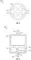
- FIG. 4is a cross-sectional view of one embodiment of a compact percutaneous lead with two sets of redundant power leads.
- FIG. 5is a schematic representation of one embodiment of an implantable controller with two unequal capacity rechargeable storage devices.
- FIG. 6is a schematic representation of one embodiment of a mobility-enhancing hybrid ventricular assist system including a blood pump, a controller, rechargeable power storage devices, and a compact percutaneous lead.
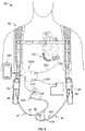
- FIG. 7depicts a front view of one embodiment of a mobility-enhancing hybrid ventricular assist system implanted in a patient with the hybrid system connected to an external controller and external batteries contained in a carrier system.
- FIG. 8depicts a front view of one embodiment of a mobility-enhancing hybrid ventricular assist system implanted in a patient with the hybrid system connected to external batteries contained in a carrier system and in wireless communication with an external interface.
- An exemplary hybrid blood pump systemgenerally includes a blood pump, at least one internal rechargeable power storage device, and a percutaneous lead.
- the hybrid blood pump systemis configured to enhance the freedom and mobility of the user by allowing for normal function of the blood pump when the user is disconnected from an external power source.
- the internal rechargeable power storage devicecan store sufficient power to provide for the normal operation of the blood pump for an extended period of time (e.g., at least about 30 minutes and ideally at least 2 hours).
- the percutaneous leadallows for the percutaneous transfer of power from an external source to normally operate the blood pump and to recharge the internal power storage device.
- the hybrid systemwhich can run on power supplied by either an internal rechargeable power storage device, or by a direct connection with an external power source via the percutaneous lead, provides a system that allows for increased mobility while avoiding problems associated with fully implanted systems that transfer power transcutaneously. Exemplary hybrid systems are described below in connection with the attached figures.
- FIG. 1is a front view depicting an example of a mobility-enhancing hybrid ventricular assist system 10 including an internal blood pump assembly 100 , an internal controller assembly 200 connected to the blood pump assembly via an electrical conduit 230 , internal rechargeable power storage device(s) 350 contained within the controller assembly 200 (see FIG. 2 ), and a percutaneous lead 400 connected to the controller assembly 200 and exiting the body.
- the power storage device(s) 350include one or more “smart” lithium-chemistry batteries that are readily rechargeable.
- An external monitoring device 500can perform wireless 2-way communication with the internal components of the hybrid system 10 , for example, via wireless telemetry device 220 (see FIG. 2 ).
- FIG. 2is a close-up of the system of FIG.
- the internal pump assembly 100can also include an implantable blood pump 110 fluidly connected to an internal chamber of a heart and circulatory system, and a programming wand 510 included in the external monitoring device 500 for communication with the controller assembly 200 .
- the programming wandcan include a built-in display 512 for displaying menus, data, and the like, and a external wireless telemetry device 514 for communicating with the internal telemetry device 220 and one or more user-selectable buttons 516 (e.g., four buttons in this embodiment).
- the blood pump 110can be a ventricular assist device (VAD).
- VADventricular assist device
- a VADis a mechanical circulatory device that is used to partially or completely replace the function of a failing heart. Some VADs are intended for short term use, typically for patients recovering from heart attacks or heart surgery, while others are intended for long term use (e.g., months, years, and the remainder of a user's life), typically for patients suffering from congestive heart failure. VADs are designed to assist either the right (RVAD) or left (LVAD) ventricle, or both at once (BiVAD).
- VADscan be designed with an axial flow or centrifugal flow configuration. The former can be configured with an impeller suspended by journal bearing such as a ball and cup, or by magnetic or hydrodynamic forces.
- the blood pumpcan be configured with an impeller suspended by at least magnetic forces, hydrodynamic forces, or a combination of both.
- the blood pumpcan be an artificial heart, which is designed to completely take over cardiac function and may require the removal of a patient's heart. It should be appreciated that the technical features disclosed herein apply equally to any variation of the blood pump as described in this disclosure.
- a hybrid ventricular assist system 10can include the internal pump assembly 100 connected in parallel with the left ventricle of a heart such that the pump assembly 100 can mechanically augment the pumping of blood performed by the left ventricle.
- FIGS. 1 and 2depict the internal pump assembly 100 including the blood pump 110 , such as the HeartMate® II LVAD, a product of the Thoratec® Corporation of Pleasanton, Calif.
- FIGS. 7 and 8depict the pump assembly 100 that includes a different embodiment of an LVAD.
- the pump assembly 100can be installed to temporarily provide mechanical assistance while an individual waits for a transplant.
- the pump assembly 100can be implanted to reduce the stress on a person's heart, allowing it to heal and regain normal function, and later be removed.
- the pump assembly 100can be implanted as a substantially permanent option.
- the blood pumpcan include internal pump control circuitry.
- Internal pump control circuitrycan also be included in a separate housing (e.g., with internal rechargeable power storage device).
- Internal pump control circuitryfunctions to make the blood pump pump when power is supplied to the blood pump and is distinct from a controller that may alter the pumping operation, alter how power is being supplied to the blood pump and/or perform other functions for the system, such as detecting whether the system is being provided with power from an external power source and detecting whether the internal rechargeable power source needs to be recharged from the external power source.
- One or more power storage devices 350can be included in a single housing.
- this single housingalso includes a controller device 210 .
- a controller device 210 and the power storage device(s) 350can be within the single controller assembly 200 .
- a controller assemblycan include two (or more) power storage devices 350 .
- the controller assemblycan include a single power storage device, or any number of power storage devices.
- the hybrid system 10can include one or more housings, separate from the controller assembly, each containing one or more power storage devices.
- the power storage device(s) 350can be implanted in a location separate from the blood pump assembly 100 , for example, in the thorax or the abdomen of a patient.
- the housingcan be implanted in the abdominal quartet, below the thorax, within the mussel layers.
- the power storage device(s) 350can be implanted in other body locations, such as within the leg of a patient.
- a housing containing the power storage device(s) 350can be positioned and shaped to maximize the dissipation of heat from the power storage device(s) 350 .
- the housingcan be positioned to maximize the amount of blood circulating around the housing.
- the housing containing the power storage device(s) 350can be implant at or near the core of the patient.
- Implanting the power storage device(s) 350 within a housing in a location separate from the blood pump assembly 100can allow for the use of a larger power source than can normally be accommodated within the blood pump assembly. It can be desirable to limit the volume of devices implanted adjacent to the heart. As such, a battery implanted inside or in close proximity to a blood pump assembly 100 is limited in size, and thus electrical capacity. To allow for a longer period of time in which the user is not connected to an external power source, the power storage device(s) can be advantageously included in a location separate from the blood pump assembly.
- Locations such as the abdomenmay be able to accept larger implanted devices, and thus allow for larger power storage device(s), which can be used to increase the period of time that the internal blood pump can function normally without being coupled to an external power source.
- having the power storage device(s) 350 in a location separate from the blood pump assembly 100can reduce the probability of heat from the internal power storage device(s) damaging the heart and/or tissue adjacent the heart.
- a location of the power storage device separate from the blood pump assemblyallows for outpatient replacement of the power storage device, if necessary.
- a locationcan also be selected in accordance with the level of ease in which the power storage device can be replaced.
- the total volume of the power storage device(s) 350can be 1 in 3 or greater. In some embodiments, the total volume of a housing including the power storage device(s) is between about 1 in 3 and about 20 in 3 . In some embodiments, the power storage device(s) are designed with various options based on size and run time, including but not limited to providing greater than 30 minutes of blood pump normal operation, greater than 1 hour of blood pump normal operation, greater than 2 hours of blood pump normal operation, and greater than 3.5 hours of blood pump normal operation.
- the housingcan, in preferred embodiments, have a volume of between 5 in 3 and 13 in 3 (e.g., about 10 in 3 ). The total volume of a housing would also depend on the material used and the battery technology.
- the larger the rechargeable power sourcethe larger the charge storage capacity and thus the longer the run time.
- the smaller housing containing a smaller rechargeable power sourcewould have a smaller charge storage capacity, a shorter run time, but a lower risk of infection.
- the housingcan be hermetically sealed.
- the housingcan be made of commercially available inert materials including both biocompatible metals, biocompatible polymers, and biocompatible ceramics, such as stainless steel, titanium and titanium alloys (e.g., Ti-6Al-4V grade 5 titanium), cobalt-chromium alloys, polyethylene (e.g., UHMWPE), PEEK polymers, and combinations thereof.
- the housing materialcan also be selected for its ability to dissipate heat as well as its ability to provide an electrical and/or magnetic shield should it be used to house an internal controller.
- the housingcan be substantially flat.
- the housingcan have a thickness of about 0.3 to 1 inch, a width of about 1.5 to 3.5 inches, and a length of about 3 to 6 inches.
- the housinghas dimensions approximating the dimensions of a standard cigarette pack (about 2.6 inches ⁇ about 4.6 inches ⁇ about 0.6 inches).
- the housingcan have a slightly curved configuration bent to confirm to the contours of a human abdomen, similar to a whisky flask.
- the housingcan also have rounded corners. This can allow a user to have increased freedom of movement because batteries of this volume can be used to provide power for normal pump operation for extended periods of time without the use of an external power supply.
- a flat configurationcan allow for a more superficial placement and replacement, if necessary.
- a flat configurationcan also facilitate the dissipation of heat.
- the housingcan also have rounded corners and other features to reduce injury to surrounding tissue.
- An outer surface of the housingcan having a coating or other features that reduce the instances of pocket infection.
- the size of the implant adjacent to the heartshould be minimized. As the size of the implant increases, so does the risk of a pocket infection. If the pump pocket becomes infected, the infection could enter the blood stream causing sepsis, which can be extremely hazardous to an already immuno-compromised patient.
- An implant of minimal size adjacent to the heartcan allow for placement of the device entirely within the thorax which may simplify the surgery and allow for a shorter recovery time.
- the power storage device(s) 350can be one or more rechargeable batteries.
- the power storage device(s) 350can be one or more lithium ion batteries.
- the power storage device(s) 350can be one or more lithium polymer batteries.
- the power storage device(s) 350may comprise a capacitor device capable of being recharged over time and discharging power sufficient for normal operation of the system 10 .
- fuel cell technology using hydrogen as an energy storage vehiclemay provide a viable option, using electricity provided by an external power source to electrolyze water within the body to generate additional hydrogen.
- other high density power storage devicesmay be developed in the future and can be used in as the power storage device(s) 350 as described herein.
- some batteriescan include internal circuitry that prevents the batteries from becoming fully depleted. As such, if the charge level within such a battery falls below a predetermined level, this internal circuitry can cause the battery to stop delivering power to avoid irreversibly damaging the battery. Accordingly, if the charge within a battery falls below this predetermined level, the battery is functionally depleted.
- the controller device 210can determine whether the energy remaining in a particular power storage device 350 has fallen below a predetermined threshold and can stop transferring power from a power storage device 350 if the remaining energy falls below that predetermined threshold. Still, another possibility is to have the controller device 210 send a warning signal when the power capacity drops below a certain level and into a range where operation of the pump is still possible, but before it is considered functionally depleted.
- the internal power storage devices 350can be recharged using energy from the external power source.
- Charge timecan depend on the size of the battery and the charge rate limitations for heat dissipation in the charge electronics and the heat dissipation in the percutaneous lead.
- power storage devicescan be recharged in 50% to 400% of the discharge time.
- the internal power storage devicescan be recharged from a functionally depleted state to having a full charge in less than 30 minutes.
- the percutaneous lead 400can include a proximal end 402 located internal to the user and a distal end 404 located external to the user, with a portion 406 that traverses the skin.
- the proximal end 402can be electrically connected to the controller assembly 200 and the distal end 404 can be removably coupled to an external power supply (not shown).
- a cap 410can be used to protect the external physical structure of the distal end 404 and connector, as well as the exposed metal connections that can be coupled to the external power supply.
- this capcan be designed to be fluid resistant (or fluid proof).
- the capcan prevent moisture from seeping into the connector and reaching the metal connections.
- the capcan also to prevent any electrical conduction from any outside element with the metal connections.
- the capcan be waterproof and fluid resistant.
- the cap structurecan be made of a metallic or non-conducting material; in either case, the cap design will have insulation to prevent shorting of the metal connections or conduction of electricity between an external source and the metal connections.
- the distal end 404 of the percutaneous lead 400can be electrically coupled to an external power source.
- the external power sourcecan supply power for normal operation of the internal components of the hybrid system 10 (e.g., the pump assembly 100 , the controller assembly 200 , and the like) and to recharge the power storage device(s) 350 .
- the external power sourcecan be in the form of external batteries, an external power source plugged into a traditional wall socket such that it can convert AC electricity to DC electricity, and the like.
- the percutaneous lead 400is coupled to an external power source that is plugged into a wall socket, the user is limited in the distance that he can travel. In these circumstances, the user may be limited to a single room, a single building, and the like.
- the usermay be limited from performing activities requiring a high degree of freedom of physical movement and/or that involve exposure to liquids, including but not limited to daily activities such as taking a bath, grocery shopping, physical and sporting activities like swimming, golf, tennis, etc., and household maintenance.
- the hybrid ventricular assist system 10can be configured to be electrically coupled via the percutaneous lead 400 to a portable external power source, such as external batteries.
- a portable external power sourcesuch as external batteries.
- FIGS. 7 and 8depict a portable system for carrying external batteries.
- the percutaneous leadis connected to a portable external power source, the user can experience improved mobility, comfort, independence, and self-esteem when compared to being coupled to a power source plugged into a wall socket.
- the usercan wear a garment that is designed to contain rechargeable batteries such that the user is free to perform household chores, travel to the grocery store, go on a walk, etc.
- the hybrid ventricular assist system 10can be used for extended periods of time without the use of an external power supply. For example, when a user desires to have a greater freedom of movement and comfort, the user can disconnect the distal end 404 of the percutaneous lead 400 from an external power source, thus freeing him from the limitations imposed by such an external power source.
- the internal power storage device(s) 350can supply the power for the normal operation of the hybrid system 10 (e.g., the pump assembly 100 , the controller assembly 200 , and the like) for an extended period of time (e.g., greater then 30 minutes, greater than 1 hour, greater than 2 hours, greater than 3.5 hours, and the like, based on the size and capacity of the internal power storage device 350 ). While unplugged from all external power sources, the user experiences greater freedom to take part in physical and passive activities, such as swimming and bathing, that would otherwise be complicated by external cords, batteries, and the like.
- the external power sourcecan be used to not only support normal operation of the hybrid system 10 , but also to recharge the internal power storage device(s) 350 .
- the internal power storage device(s)can be advantageously recharged from a functionally depleted state to a fully recharged state in less than 30 minutes.
- a blood pump systemcan use a transcutaneous power system to wirelessly transfer power from an external power source to components implanted in a user.
- powercan be transmitted from the external source to the internal components by generating a magnetic field in the external coil and converting the magnetic field to electrical power in the internal coil, which is distributed to the other internal components.
- transcutaneous power systemscan be limited in the rate of power transferred, for example, by the size of the coils.
- larger coilscan be used.
- larger coilsoccupy additional internal space, which can result in an increased possibility of infection, and can result in the user carrying additional external equipment. Smaller coils, however, have slower transfer rates.
- transcutaneous power transmissioncan lose power during transmission, some of which is lost as heat within the tissues separating the internal and external transmission coils. This heating can be damaging to tissue.
- a user wearing external batteries, each with a fixed energy capacitywould have less time in between battery changes when using a transcutaneous power transfer system when compared to transferring power via the percutaneous lead 400 .
- fixation of the coilsis critical for maintaining optimal alignment. As the coils become more decoupled (i.e. through misalignment and/or separation), efficiency of the transfer drops.
- the percutaneous lead 400can, in some embodiments, have a cross sectional area of less than about 0.10 square inches (e.g., a diameter that is less than about 0.3 inches).
- a reduced-diameter percutaneous lead 400a smaller opening in the user's skin is used to accommodate the percutaneous lead 400 .
- Reducing the diameter of the percutaneous lead that traverses the skin of the userhas the beneficial effect of exposing less tissue, thus decreasing the possibility of infection around this opening.
- a larger diameter percutaneous leadcan increase transfer of both power and data to the internal components, a reduction in the diameter of the percutaneous lead can be achieved by using the percutaneous lead to only transfer power.
- control datais transmitted via wireless communication, thus allowing for a reduction in the diameter of the percutaneous lead 400 .
- exemplary percutaneous leads that include redundant sets of wires for transferring both power and datacan have diameters that exceed 0.75 inches in diameter.
- a larger diameter percutaneous leadmay be used to reliably transfer both power and data to the internal components.
- the percutaneous leadcan have a diameter that is greater than 0.5 square inches (e.g., greater than 0.75 inches in diameter).
- FIG. 4is a cross-sectional view of a compact percutaneous lead 400 with two sets of redundant power leads.
- the percutaneous lead 400can include a flexible outer housing 408 enclosing redundant electrical lead sets 440 and 445 , for example as discussed in U.S. patent application Ser. No. 12/472,812, filed May 27, 2009, which is hereby incorporated by reference.
- electrical energycan be supplied from an external power source to the internal components of the hybrid ventricular assist system 10 (e.g., the blood pump 110 , the controller device 210 , the power storage device(s) 350 , and the like).
- Each of the lead sets 440 and 445can be capable of transferring all of the power for normal operation of the hybrid system 10 , including recharging of the power storage device(s) 350 , resulting in fully redundant energy transfer.
- the system 10can be fully powered by the one set 440 and 445 that remains intact.
- powercan be transferred by using non-damaged conductors from each set
- the percutaneous lead 400contains only the lead sets 440 and 445 for transferring energy
- the percutaneous lead 400has a smaller cross-sectional area than in cases where additional wires are included for data transfer.
- the cross-sectional area of the percutaneous lead 400can be further decreased by, for example, including only a single set of power transfer wires.
- the cross-sectional area of the percutaneous lead 400may be decreased by decreasing the diameter of the lead sets 440 and 445 (e.g., by configuring them such that they are not fully redundant).
- each lead set 440 and 445may be configured to carry only a percentage (e.g., less than 100%, 95%, 64%, 50%, and the like) of the total energy used during normal operation of the system 10 and recharging of the power storage device(s) 350 .
- each lead set 440 and 445may be configured to supply sufficient power for normal operation of the hybrid system 10 and to trickle charge the power storage device(s) 350 .
- the hybrid system 10can be supplied with power for normal operation and with sufficient power such that the power storage device(s) 350 can be quickly charged (e.g., the power storage devices can be recharged in less than 60 minutes).
- the systemcan have a longer recharge time, depending on the type of power storage device and the percutaneous lead.
- the system 10can operate normally with the exception of charging the internal power storage device(s) 350 , which will be accomplished at a slower rate.
- a redundancyis provided for normal operation of the system 10 while further reducing the diameter of the percutaneous lead 400 , thus further decreasing the possibility of infection.
- the hybrid ventricular assist system 10can include other features that decrease the cross-sectional area of the percutaneous lead 400 while allowing for power and data transfer through the lead 400 .
- the lead 400can include the lead sets 440 and 445 configured to transfer power from a power source external to a user to the internal components of the system 10 . Power transferred from an external power source, for example, can be used for normal operation of the blood pump 110 and to recharge the internal power storage device(s) 350 . Since power for the normal operation of the internal components of the system 10 can come from the power storage device(s) 350 , power transfer can be temporarily discontinued through one or more of the lead sets 440 and 445 , thus leaving one or more of the lead sets 440 and 445 available for the transfer of data.
- the percutaneous leadincludes two non-redundant sets of wires, one set for charging the power storage device(s) 350 and one set for providing power to the blood pump. In such an embodiments, a disabled recharging set can be rerouted to simply provide power to the blood pump.
- FIG. 6is a schematic representation of the mobility-enhancing hybrid ventricular assist system 10 including the blood pump assembly 100 , the controller assembly 200 , the rechargeable power storage devices 350 and 355 , and the compact percutaneous lead 400 .
- the hybrid system 10can be configured to reduce the diameter of the percutaneous lead 400 .
- the hybrid system 10includes internal controller assembly 800 that can control functions of the hybrid system 10 and can wirelessly communicate with external components. Due at least in part to the presence of the internal controller assembly 800 , data communication between the internal controller assembly 800 and external components can be transmitted in a manner other than through the percutaneous lead 400 .
- the controller device 210can be electrically connected to the two power storage device(s) 350 and 355 with lead sets 860 and 861 , respectively, and to the wireless telemetry device with redundant data lead sets 862 and 863 . Furthermore, the controller device 210 can be electrically connected to the pump assembly with two redundant power lead sets 864 and 865 and two redundant data lead sets 866 and 867 . In this example, the internal controller 210 is electrically connected to the pump assembly 100 by eight wires, but only four wires are used in the percutaneous lead 400 . In examples where a controller device is external to the patient, additional wires may be used in the percutaneous lead that traverses the skin of the user.
- the percutaneous lead 400can additionally include other features that reduce a user's possibility of infection. As described above, an opening in the skin exposes tissue to infection. Additionally, movement of the portion 406 of the percutaneous lead 400 that traverses the skin opening in relation to the skin opening itself can cause damage to tissue surrounding the percutaneous lead 400 , thus increasing the possibility of infection.
- the hybrid system 10can be configured to include features that reduce movement of the internal portion of the percutaneous lead 400 relative to the user.
- the percutaneous lead 400can include a strain-relief portion 420 for anchoring the percutaneous lead 400 to the user and for reducing the strain on the portion of the percutaneous lead exiting the user's body.
- the percutaneous lead 400can include a low-force breakaway portion 430 that can separate when subjected to a pulling force that is less than the force expected to cause damage to the tissue surrounding the skin opening. Due to the presence of the internal power storage device, the percutaneous lead does not act as a lifeline, thus a breakaway connection can be used because an accidental disconnection will not result in a loss of power to the blood pump. When the distal end 404 of the percutaneous lead 400 is pulled with a force greater than the break-away force of the breakaway portion 430 , the percutaneous lead 400 can reversibly separate into two portions, thus reducing the strain on the portion of the percutaneous lead 400 entering the skin opening.
- the two portionscan be re-joined at the breakaway portion 430 when the stress on the breakaway portion 430 falls below the break-away force. While the percutaneous lead 400 is separated into the two portions, sufficient power to maintain normal operation of the hybrid system 10 can be supplied by the internal power storage device(s) 350 . When the percutaneous lead 400 is reconnected, power to maintain normal operation of the hybrid system 10 can once again be supplied by the connected external power source, while also recharging the internal power storage device(s) 350 .
- the percutaneous leadcan be connected to the external power source by use of a connector.
- the connectorcan be flat, square, round, or any other shape.
- the connectorcan provide a fluid resistant or fluid proof connection.
- the connectorcan prevent liquid water proof and water vapor proof.
- the blood pumpcan be controlled by internal control circuitry.
- the control circuitrycan be a part of the blood pump assembly 100 .
- the control circuitrye.g., controller device 210
- the control circuitrycan be within the same housing containing the rechargeable power storage device(s) 350 , as depicted in FIGS. 1, 2, and 3B .
- control circuitrycan be within a dedicated implantable housing separate from both the blood pump assembly 100 and the housing containing the rechargeable power storage device(s) 350 , as depicted in FIGS. 3A, 7, and 8 .
- Internal control circuitrye.g., the controller device 210
- the internal control circuitrycan include, but is not limited to, one or more features to monitor the operation of the hybrid ventricular assist system 10 , to monitor the user (e.g., to detect blood pressure), to control predetermined functions of the hybrid system 10 (e.g., to control how power is supplied to the blood pump), and to inform the user of particular information regarding operation of the hybrid system 10 (e.g., by vibrating or by sending a signal to an external device).
- the internal control circuitrycan include features for controlling the speed of the pump 110 .
- the internal control circuitrycan monitor functions of the system 10 , such as the electrical charge level of (i.e. usable energy remaining in) the power storage device(s) 350 .
- the internal control circuitrycan inform the user of alerts and alarms pertaining to the operation of the hybrid system 10 , such as alerting the user when the charge level of one or more of the power storage devices 350 has fallen below a predetermined threshold, or signaling an alarm when a malfunction in the system 10 has occurred.
- the internal control circuitrycan inform the user of a condition, for example, by initiating an internal vibrator, signaling a remote controller via the wireless telemetry unit 220 , causing a light to flash, and the like.
- an external portion of the percutaneous lead 400e.g., the cap 410 , the distal end 404 of the percutaneous lead 400 , and the like
- the controllercan direct power though wires provided in the percutaneous lead 400 to a light in an external portion of the percutaneous lead or in the cap.
- the controllercan monitor the inlet and outlet pressures of the pump 110 , determine blood flow through the pump assembly 100 , determine an activity level of the user and thereby change the speed of the pump, and the like.
- These controller functionscan also be preformed using an external controller that communicates with the internal controller, for example using an external communication device that performs wireless 2-way communication.
- the controllercan also detect whether power is being provided through the percutaneous lead and to control whether that power is used to simply operate the blood pump or to also recharge the internal power supply.
- the internal controllercan also include electrical circuitry to detect and shut down (if necessary) failed conductors in the percutaneous lead and/or between the controller and blood pump or other internal housings. This can be accomplished by detecting increased or decreased electrical resistance. In some embodiments, the controller can then use a redundant conductor.
- the controllercan also provide different alarms depending on whether power is being supplied via the percutaneous lead, and in some embodiments depending on which external power source is active (e.g., external portable battery versus converted AC power source).
- Internal alarmscan include internal vibrators (e.g., piezoelectric buzzers).
- External alarmscan include lights and/or audible alarms.
- the controllercan also include a memory buffer to store information.
- the member buffercan store acquired data, such as pump speed and physiological data of the patient (e.g., blood pressure).
- the member buffercan also be used to record information about how the pump system is operating, including error information and/or battery life.
- the information in the memory buffercan be downloaded to an external system via the percutaneous lead and/or via a telemetry system.
- the memory buffercan provide a means to record information when the user is disconnected and/or away from external components.
- the hybrid ventricular assist system 10can be electrically coupled via the percutaneous lead 400 to an external power source that can supply power for normal operation of the hybrid system 10 .
- the external power sourcecan be external batteries, a wall socket, or the like.
- An external power sourcecan have different levels of technological complexity, ranging from a simple AC transformer/adapter to a control console that is used to diagnose, control, and/or modify functions of the pump.
- the external batteriescan be part of or connected to an external controller, as depicted in FIG. 7 .
- the percutaneous lead 400can be directly connected to external batteries. Power supplied by the external power source can be used to recharge the power storage device(s) 350 .
- the hybrid system 10can also include an external controller (e.g., an external controller 500 ) that can be used in conjunction with or in lieu of the internal controller device 210 .
- the hybrid ventricular assist system 10can include the external monitoring device 500 in wireless communication with the internal components of the hybrid system 10 (e.g., the controller device 210 , the wireless telemetry device 220 , the pump assembly 100 , and the like).
- the external controller 500can include the programming wand 510 .
- the programming wandcan include the built-in display 512 for displaying menus, data, and the like, the external wireless telemetry device 514 for communicating with the internal telemetry device 220 , and the one or more user-selectable buttons 516 (e.g., four buttons in this embodiment) for navigating menus, selecting features, inputting data, and the like.
- the external electrical interfacecan include electronics to detect and shut down (if necessary) any faulty conductors in the percutaneous cable.
- FIG. 3Ais schematic representation of one embodiment of the mobility-enhancing hybrid ventricular assist system 10 including a controller assembly 600 and a separate power storage assembly 300 .
- the hybrid system 10also includes the internal blood pump assembly 100 , one or more rechargeable storage devices (e.g., the power storage device 350 , and the like) included in the power storage assembly 300 , and the compact percutaneous lead 400 .
- the controller assembly 600can be implanted in, for example, the thorax, the abdomen, or other parts of a patient and can be electrically connected to the pump assembly 100 via the electrical conduit 230 such that the controller assembly 600 can control functions of and monitor the pump assembly 100 .
- the controller assembly 600can be connected to the power storage assembly 300 via an electrical conduit 330 and can control charging of the power source contained within the power storage assembly 300 .
- Power for normal operation of the hybrid system 10can be supplied by the power storage assembly 300 .
- the power storage device 350for example, can be directly electrically connected to the controller assembly 600 , the pump assembly 100 , and the like, and can be implanted in the thorax, the abdomen, or other parts of the user in a location separate from those of the controller assembly 600 and the pump assembly 100 . In other embodiments, the power storage device 350 may indirectly provide power to the pump assembly 100 . Power storage devices, in addition to or in lieu of the power storage device 350 , can be included in one or both of the blood pump assembly 100 and the controller assembly 600 .
- FIG. 3Bis a schematic representation of certain embodiments of the mobility-enhancing hybrid ventricular assist system 10 connected to an external power source 20 .
- the hybrid system 10can include features that allow for power to and control of an internal pump without constant connection to external devices.
- the hybrid system 10can include the internal controller assembly 200 that includes the controller device 210 , the wireless telemetry device 220 , and the two rechargeable power storage devices 350 and 355 .
- the controller assembly 200can be implanted in a single location (e.g., in the thorax, the abdomen, and the like) with the electrical conduit 230 electrically connecting elements contained within the controller assembly 200 (e.g., the controller device 210 , the wireless telemetry device 220 , the rechargeable power storage devices 350 and 355 , and the like) to the pump assembly 100 .
- the electrical conduit 230can be removably coupled to the controller assembly 200 via the bulkhead connector 202 and to the pump assembly via the bulkhead connector 102 .
- the percutaneous lead 400can be coupled to the controller assembly 200 via a bulkhead connector 204 .
- the electrical conduit 230has a larger diameter than the percutaneous lead 400 , as the electrical conduit 230 includes wires for both the transmission of power and data between the controller assembly 200 and the pump assembly 100 .
- the controller assembly 200can include the power storage device 350 and the optional power storage device 355 that are substantially equivalent and that can each supply electrical energy to the individual components of the hybrid ventricular assist system 10 (e.g., the controller device 210 , the wireless telemetry device 220 , the pump assembly 100 , and the like).
- the power storage devices 350 and 355can include one or more direct electrical connections to the pump assembly 100 , while in other examples energy can be transferred to the pump assembly 100 via the controller device 210 .
- energycan be transferred to other components of the hybrid system 10 (e.g., the wireless telemetry device 220 and the like) either directly, or through intervening components.
- the hybrid system 10can be configured such that each of the power storage devices 350 and 355 is a redundant source of energy for all components of the system 10 , thus the system 10 can function normally even when only one of the power storage devices 350 and 355 is supplying energy to the hybrid system 10 .
- Powercan also be supplied for normal operation of the hybrid system 10 by an external power source (e.g., the external power source 20 ) when connected to the percutaneous lead 400 . When connected in this manner the internal power storage devices 350 and 355 can be charged by the external power source 20 .
- FIG. 5is a schematic representation of an implantable controller assembly 700 with two unequal capacity rechargeable storage devices.
- the hybrid ventricular assist system 10can include the internal controller assembly 700 that includes the controller device 210 , the wireless telemetry device 220 , and rechargeable power storage devices 360 and 365 .
- the controller assembly 700(including the internal power storage devices 360 and 365 ) can be implanted in a single location (e.g., in the thorax, the abdomen, and the like) with the electrical conduit 230 electrically connecting elements contained within the controller assembly 700 (e.g., the controller device 210 , the wireless telemetry device 220 , the rechargeable power storage devices 360 and 365 , and the like) to the pump assembly 100 .
- the electrical conduit 230can be removably coupled to the controller assembly 700 via a bulkhead connector 702 and the percutaneous lead 400 can be coupled to the controller assembly 700 via a bulkhead connector 704 .
- the controller assembly 700can include the power storage devices 360 and 365 that can supply electrical energy to the individual components of the hybrid ventricular assist system 10 (e.g., the controller device 210 , the wireless telemetry device 220 , the pump assembly 100 , and the like) and that do not have substantially equivalent electrical energy capacities.
- the hybrid system 10can include one or more direct electrical connections from the internal power storage devices (e.g., the devices 350 , 355 , 360 , 365 , and the like) to the pump assembly 100 (see FIG. 2 ). In other examples, energy can be transferred from the internal power storage devices to the pump assembly 100 via the controller device 210 .
- each of the power storage devices 360 and 365is a redundant source of power for normal operation of the system 10 , thus the system 10 can function normally even when only one of the power storage devices 360 and 365 is supplying power to the hybrid system 10 .
- the power storage devices 360 and 365can be configured to store different amounts of energy.
- the power storage device 360can be configured with a larger capacity than the power storage device 365 .
- initial powercan be supplied by the power storage device 360 and the power storage device 360 can be configured to power the system 10 for a period of time greater than 30 minutes.
- the controller device 210can notify the user (e.g., by initiating a vibrating alarm, causing the cap 410 to illuminate, sending a signal to an external controller, and the like) that the power storage device 360 has been depleted and the system 10 is operating using power supplied from power storage device 365 .
- the power storage device 365can be configured to supply the power for normal operation of the system 10 , for example, for a period of 10 minutes, to allow a user to reconnect the system 10 to an external power supply.
- the hybrid ventricular assist system 10can be configured to reduce the diameter of the percutaneous lead 400 .
- the hybrid system 10includes internal controller assembly 800 that can control functions of the hybrid system 10 and can wirelessly communicate with external components. Due at least in part to the presence of the internal controller assembly 800 , data communication between the internal controller assembly 800 and external components can be transmitted in a manner other than through the percutaneous lead 400 . Since the percutaneous lead 400 can be limited to the transfer of electrical energy, the resulting diameter of the percutaneous lead 400 can be smaller than if data transfer also took place through the percutaneous lead 400 .
- the controller device 210can be electrically connected to the power storage device 350 and the optional power storage device 355 with lead sets 860 and 861 , respectively, and to the wireless telemetry device 220 with redundant data lead sets 862 and 863 . Furthermore, the controller device 210 can be electrically connected to the pump assembly with two redundant power lead sets 864 and 865 and two redundant data lead sets 866 and 867 . In this example, the internal controller 210 is electrically connected to the pump assembly 100 by eight wires, but only four wires are used in the percutaneous lead 400 . In examples where a controller device is external to the patient, additional wires may be used in the percutaneous lead that traverses the skin of the user.
- FIG. 7is a front view depicting an embodiment of the hybrid ventricular assist system 10 coupled to a portable external controller 30 and two external batteries 40 .
- the hybrid system 10includes the internal blood pump assembly 100 (including a centrifugal blood pump 150 ), an internal controller assembly 900 , the internal rechargeable power storage assembly 300 , including one or more rechargeable storage devices (e.g., the devices 350 , 360 , 365 , and the like), and the compact percutaneous lead 400 .
- the controller assembly 900can be implanted in, for example, the thorax, the abdomen, or other part of a patient, and can be electrically connected to the blood pump 150 such that the controller assembly 900 can control functions of and monitor the pump assembly 100 and control charging of the power sources contained within the power storage assembly 300 .
- Power for normal operation of the hybrid system 10can be supplied by the power storage assembly 300 .
- the power storage assembly 300can, for example, be electrically connected to the controller assembly 900 , the pump assembly 100 , and the like, and can be implanted in the thorax, the abdomen, or another part of the user in a location separate from those of the controller assembly 900 and the pump assembly 100 . This can allow for outpatient replacement of the power storage device if necessary.
- the hybrid ventricular assist system 10can be electrically coupled via the percutaneous lead 400 to an external controller and power source.
- a non-portable power sourcee.g., a power source plugged into a conventional wall socket
- the percutaneous lead 400can be uncoupled from the non-portable external controller and power source (not shown) and coupled to the portable external controller 30 and the two external batteries 40 .
- the power for normal operation of the blood pump 150can be supplied by the external batteries 40 , thus not decreasing the energy level contained within the internal power storage assembly 300 .
- power supplied by the external batteries 40can be used to recharge the power storage assembly 300 .
- the usercan wear a garment, such as a holster vest 50 that can include battery holders 52 such that the weight of the external batteries 40 can be substantially supported by the shoulders of the user.
- a waist belt 54can be included with the holster vest 50 to firmly hold the battery holders 52 (including the coupled batteries 40 ) and the external controller 30 firmly against the user.
- the distal end 404 of the percutaneous lead 400 coupled to the external controller 30the user is able to move around untethered, for example, by an external power source plugged into a wall socket.
- the usercan experience improved mobility, comfort, independence, and self-esteem when compared to being coupled to a power source plugged into a wall socket.
- a garmente.g., the holster vest 50 , a carrying case, and the like
- the rechargeable batteries 40such that the user is free to perform household chores, travel to the grocery store, go on a walk, etc.
- a useris not restricted by a cord plugged into a wall and is free to partake in many normal day-to-day activities, thus leading to increased independence and self-esteem.
- the external power sourcesince the external power source is worn with the user, the possibility of pulling on the percutaneous lead 400 and damaging surrounding tissue is reduced, leading to decreased possibility of infection and increased comfort.
- the usercan uncouple the percutaneous lead 400 from the external controller 40 .
- a usermay be restricted from performing certain activities while wearing a garment containing electronic devices. For example, certain forms of physical exercise, such as swimming, would be difficult while wearing a garment containing electronic devices.
- a portable onesuch as batteries included in a garment, could be an impedance and inconvenience for activities such as gardening, a brisk walk, a short game of tennis or golf, etc.
- a usercan uncouple the percutaneous lead 400 from all external devices, remove the external devices (e.g., the holster vest 50 , the battery holsters 52 , the belt 54 , the external controller 30 , the external batteries 40 , and the like) for an extended period of time for performing activities that might otherwise not be possible.
- the external devicese.g., the holster vest 50 , the battery holsters 52 , the belt 54 , the external controller 30 , the external batteries 40 , and the like
- Being connected to an external power sourceeven a portable battery, can also complicate certain relatively passive activities, such as taking a bath, that include exposure to liquids.
- FIG. 8is a front view depicting another embodiment of the hybrid ventricular assist system 10 coupled to two external batteries 40 .
- the hybrid system 10can include the internal blood pump assembly 100 (including the centrifugal blood pump 150 ), an internal controller assembly 1000 , the internal rechargeable power storage assembly 300 (e.g., not contained within the controller assembly 1000 ), and the compact percutaneous lead 400 .
- the hybrid ventricular assist system 10can be free of an external wired controller (such as the controller 30 depicted in FIG. 7 ).
- an adapter 44can be coupled to the distal end 404 percutaneous lead 400 such that the electrical conduits 41 coupled to each of the external batteries 40 can be electrically connected to the percutaneous lead 400 (e.g., by coupling the ends 42 of the electrical conduits 41 to the adapter 44 ) without the use of an external controller 30 .
- an external devicee.g., a PDA 530
- a PDA 530can be in wireless communication with the internal controller assembly 1000 for the purpose of relaying data to the user, indicating to the user the presence of alerts and alarms, and allowing the user to program certain features of the hybrid system 10 .
- the usercan attain a greater degree of mobility by removing the external components to perform activities that might otherwise not be possible.
- the connectors of the pump assembly 100e.g., connector 102
- the controller assembly 200e.g., connectors 202 and 204
- a pocketis developed between the posterior sheath and the rectus muscle to accommodate the controller assembly 200 .
- a tunneling devicecan be utilized to create tunnels between the internal components (e.g., the pump assembly 100 and the controller assembly 200 ) for the passage of intervening conduits (e.g., the electrical conduit 230 ) and to create a tunnel between the pocket to contain the controller assembly 200 and the exit location of the percutaneous lead 400 .
- the electrical conduit 230can be inserted in the tunnel leading to the blood pump assembly 100 and secured to the bulkhead connector 102 .
- the percutaneous lead 400can be tunneled to the pocket developed for the controller assembly 200 , the controller assembly 200 can be positioned in the pocket, the conduit 230 can be secured to the controller assembly 200 using the bulkhead connector 202 , and the percutaneous lead can be secured to the bulkhead connector 204 in the controller assembly 200 .
- Pumpingmay be subsequently initiated (e.g., by placing the telemetry wand 510 over the controller assembly 200 and initiating a start-up mode) using power transferred through the percutaneous lead 400 .
- the optional display 520can display information such as hemodynamic parameters. After verifying proper functioning of the hybrid system 10 , the internal power storage device(s) 350 can then be enabled and tested. After completion of the operative procedure, chest and abdominal radiographs can be obtained to confirm component positioning.
- the hybrid system 10can include a controller assembly (e.g., the controller assembly 200 , 700 , and the like) and a power storage assembly 300 that both include rechargeable power storage devices (e.g., the devices 350 , 360 , 365 , and the like).
- a controller assemblye.g., the controller assembly 200 , 700 , and the like
- a power storage assembly 300that both include rechargeable power storage devices (e.g., the devices 350 , 360 , 365 , and the like).
- the pump assembly 100can include the controller circuitry (e.g., the controller device 210 , the wireless telemetry device 220 , and the like) used to control and monitor the function of the pump 110 .
- the controller circuitrye.g., the controller device 210 , the wireless telemetry device 220 , and the like
- such hybrid ventricular assist systemscan be free of a separate controller assembly (such as the controller assembly 200 , 700 , and the like).
- the hybrid system 10can wirelessly communicate with cell phones, PDAs, laptop computers, tablet computers, desktop computers, and the like that include the capability for wireless communication. Accordingly, other embodiments are within the scope of the following claims.
Landscapes
- Health & Medical Sciences (AREA)
- Engineering & Computer Science (AREA)
- Heart & Thoracic Surgery (AREA)
- Cardiology (AREA)
- Biomedical Technology (AREA)
- Anesthesiology (AREA)
- Mechanical Engineering (AREA)
- Hematology (AREA)
- Life Sciences & Earth Sciences (AREA)
- Animal Behavior & Ethology (AREA)
- General Health & Medical Sciences (AREA)
- Public Health (AREA)
- Veterinary Medicine (AREA)
- Human Computer Interaction (AREA)
- External Artificial Organs (AREA)
Abstract
Description
Claims (20)
Priority Applications (3)
| Application Number | Priority Date | Filing Date | Title |
|---|---|---|---|
| US16/026,947US10835655B2 (en) | 2009-12-30 | 2018-07-03 | Mobility-enhancing blood pump system |
| US17/028,739US12201822B2 (en) | 2009-12-30 | 2020-09-22 | Mobility-enhancing blood pump system |
| US18/980,448US20250108200A1 (en) | 2009-12-30 | 2024-12-13 | Mobility-Enhancing Blood Pump System |
Applications Claiming Priority (3)
| Application Number | Priority Date | Filing Date | Title |
|---|---|---|---|
| US12/649,701US8562508B2 (en) | 2009-12-30 | 2009-12-30 | Mobility-enhancing blood pump system |
| US14/057,519US10029039B2 (en) | 2009-12-30 | 2013-10-18 | Mobility-enhancing blood pump system |
| US16/026,947US10835655B2 (en) | 2009-12-30 | 2018-07-03 | Mobility-enhancing blood pump system |
Related Parent Applications (1)
| Application Number | Title | Priority Date | Filing Date |
|---|---|---|---|
| US14/057,519ContinuationUS10029039B2 (en) | 2009-12-30 | 2013-10-18 | Mobility-enhancing blood pump system |
Related Child Applications (1)
| Application Number | Title | Priority Date | Filing Date |
|---|---|---|---|
| US17/028,739DivisionUS12201822B2 (en) | 2009-12-30 | 2020-09-22 | Mobility-enhancing blood pump system |
Publications (2)
| Publication Number | Publication Date |
|---|---|
| US20180318483A1 US20180318483A1 (en) | 2018-11-08 |
| US10835655B2true US10835655B2 (en) | 2020-11-17 |
Family
ID=44188331
Family Applications (5)
| Application Number | Title | Priority Date | Filing Date |
|---|---|---|---|
| US12/649,701Active2031-05-23US8562508B2 (en) | 2009-12-30 | 2009-12-30 | Mobility-enhancing blood pump system |
| US14/057,519Active2031-11-30US10029039B2 (en) | 2009-12-30 | 2013-10-18 | Mobility-enhancing blood pump system |
| US16/026,947Active2030-07-16US10835655B2 (en) | 2009-12-30 | 2018-07-03 | Mobility-enhancing blood pump system |
| US17/028,739Active2033-03-01US12201822B2 (en) | 2009-12-30 | 2020-09-22 | Mobility-enhancing blood pump system |
| US18/980,448PendingUS20250108200A1 (en) | 2009-12-30 | 2024-12-13 | Mobility-Enhancing Blood Pump System |
Family Applications Before (2)
| Application Number | Title | Priority Date | Filing Date |
|---|---|---|---|
| US12/649,701Active2031-05-23US8562508B2 (en) | 2009-12-30 | 2009-12-30 | Mobility-enhancing blood pump system |
| US14/057,519Active2031-11-30US10029039B2 (en) | 2009-12-30 | 2013-10-18 | Mobility-enhancing blood pump system |
Family Applications After (2)
| Application Number | Title | Priority Date | Filing Date |
|---|---|---|---|
| US17/028,739Active2033-03-01US12201822B2 (en) | 2009-12-30 | 2020-09-22 | Mobility-enhancing blood pump system |
| US18/980,448PendingUS20250108200A1 (en) | 2009-12-30 | 2024-12-13 | Mobility-Enhancing Blood Pump System |
Country Status (1)
| Country | Link |
|---|---|
| US (5) | US8562508B2 (en) |
Families Citing this family (135)
| Publication number | Priority date | Publication date | Assignee | Title |
|---|---|---|---|---|
| US8628460B2 (en)* | 2009-09-21 | 2014-01-14 | Heartware, Inc. | Hard-wired implanted controller system |
| US8562508B2 (en) | 2009-12-30 | 2013-10-22 | Thoratec Corporation | Mobility-enhancing blood pump system |
| EP2575922B1 (en)* | 2010-06-07 | 2019-05-22 | Tc1 Llc | Bi-ventricular percutaneous cable |
| WO2012012552A1 (en)* | 2010-07-22 | 2012-01-26 | Thoratec Corporation | Controlling implanted blood pumps |
| US8794989B2 (en) | 2010-12-08 | 2014-08-05 | Thoratec Corporation | Modular driveline |
| JP2014502528A (en) | 2010-12-20 | 2014-02-03 | アビオメド インコーポレイティド | Method and apparatus for accurately tracking charge available in a transdermal energy transmission system |
| WO2012087811A2 (en)* | 2010-12-20 | 2012-06-28 | Abiomed, Inc. | A compact battery and controller module for a transcutaneous energy transfer system |
| DK2654878T3 (en) | 2010-12-20 | 2019-07-22 | Abiomed Inc | TRANSCUTANT ENERGY TRANSFER SYSTEM WITH A MULTIPLE OF SECONDARY COILS |
| WO2012087819A2 (en)* | 2010-12-20 | 2012-06-28 | Abiomed, Inc. | Transcutaneous energy transfer system with vibration inducing warning circuitry |
| EP2697890B1 (en) | 2011-04-14 | 2019-02-20 | Abiomed, Inc. | Transcutaneous energy transfer coil with integrated radio frequency antenna |
| US9079043B2 (en) | 2011-11-21 | 2015-07-14 | Thoratec Corporation | Transcutaneous power transmission utilizing non-planar resonators |
| US9002468B2 (en) | 2011-12-16 | 2015-04-07 | Abiomed, Inc. | Automatic power regulation for transcutaneous energy transfer charging system |
| WO2013112550A1 (en)* | 2012-01-24 | 2013-08-01 | Thoratec Corporation | Driveline cable assembly |
| US8827890B2 (en) | 2012-05-17 | 2014-09-09 | Thoratec Corporation | Touch screen interface and infrared communication system integrated into a battery |
| US8827889B2 (en) | 2012-05-21 | 2014-09-09 | University Of Washington Through Its Center For Commercialization | Method and system for powering implantable devices |
| US11621583B2 (en) | 2012-05-21 | 2023-04-04 | University Of Washington | Distributed control adaptive wireless power transfer system |
| US10291067B2 (en) | 2012-07-27 | 2019-05-14 | Tc1 Llc | Computer modeling for resonant power transfer systems |
| US9287040B2 (en) | 2012-07-27 | 2016-03-15 | Thoratec Corporation | Self-tuning resonant power transfer systems |
| WO2014018973A1 (en) | 2012-07-27 | 2014-01-30 | Thoratec Corporation | Resonant power transmission coils and systems |
| WO2014018971A1 (en) | 2012-07-27 | 2014-01-30 | Thoratec Corporation | Resonant power transfer systems with protective algorithm |
| WO2014018969A2 (en) | 2012-07-27 | 2014-01-30 | Thoratec Corporation | Resonant power transfer system and method of estimating system state |
| EP4257174A3 (en) | 2012-07-27 | 2023-12-27 | Tc1 Llc | Thermal management for implantable wireless power transfer systems |
| WO2014018974A1 (en) | 2012-07-27 | 2014-01-30 | Thoratec Corporation | Magnetic power transmission utilizing phased transmitter coil arrays and phased receiver coil arrays |
| US10383990B2 (en) | 2012-07-27 | 2019-08-20 | Tc1 Llc | Variable capacitor for resonant power transfer systems |
| US9144638B2 (en) | 2013-03-14 | 2015-09-29 | Thoratec Corporation | Blood pump rotor bearings |
| US9919088B2 (en)* | 2013-03-14 | 2018-03-20 | Yale University | Implantable heart pump controller |
| EP2984731B8 (en) | 2013-03-15 | 2019-06-26 | Tc1 Llc | Malleable tets coil with improved anatomical fit |
| WO2014145664A1 (en) | 2013-03-15 | 2014-09-18 | Thoratec Corporation | Integrated implantable tets housing including fins and coil loops |
| US9192705B2 (en) | 2013-03-25 | 2015-11-24 | Thoratec Corporation | Percutaneous cable with redundant conductors for implantable blood pump |
| EP2787581A1 (en)* | 2013-04-04 | 2014-10-08 | Berlin Heart GmbH | Implantable cable connection device |
| DE102013013700A1 (en)* | 2013-04-05 | 2014-10-09 | CircuLite GmbH | Implantable blood pump, blood pump system and method for data transmission in a blood pump system |
| US9327099B2 (en) | 2013-06-04 | 2016-05-03 | Spectrum Health Innovations, LLC | Medical tube harness |
| EP3072210B1 (en) | 2013-11-11 | 2023-12-20 | Tc1 Llc | Resonant power transfer systems with communications |
| EP3069358B1 (en) | 2013-11-11 | 2019-06-12 | Tc1 Llc | Hinged resonant power transfer coil |
| US10695476B2 (en) | 2013-11-11 | 2020-06-30 | Tc1 Llc | Resonant power transfer systems with communications |
| CN103768670B (en)* | 2014-01-23 | 2016-08-17 | 苏州大学 | A kind of artificial heart power-supply management system and management method thereof |
| WO2015134871A1 (en) | 2014-03-06 | 2015-09-11 | Thoratec Corporation | Electrical connectors for implantable devices |
| WO2015160993A1 (en) | 2014-04-15 | 2015-10-22 | Thoratec Corporation | Methods and systems for providing battery feedback to patient |
| US9849224B2 (en) | 2014-04-15 | 2017-12-26 | Tc1 Llc | Ventricular assist devices |
| US9694123B2 (en)* | 2014-04-15 | 2017-07-04 | Tc1 Llc | Methods and systems for controlling a blood pump |
| WO2015160994A1 (en) | 2014-04-15 | 2015-10-22 | Thoratec Corporation | Methods and systems for upgrading ventricle assist devices |
| US9744280B2 (en) | 2014-04-15 | 2017-08-29 | Tc1 Llc | Methods for LVAD operation during communication losses |
| US9526818B2 (en) | 2014-04-15 | 2016-12-27 | Thoratec Corporation | Protective cap for driveline cable connector |
| WO2015192076A1 (en)* | 2014-06-12 | 2015-12-17 | Heartware, Inc. | Percutaneous connector with magnetic cap and associated methods of use |
| JP6228713B1 (en) | 2014-09-03 | 2017-11-08 | ティーシー1 エルエルシー | Triple helical driveline cable and method of assembly and use |
| EP3826104B1 (en) | 2014-09-22 | 2023-05-03 | Tc1 Llc | Antenna designs for communication between a wirelessly powered implant to an external device outside the body |
| EP3200846B1 (en) | 2014-10-01 | 2020-01-15 | Heartware, Inc. | Backup controller system with updating |
| WO2016057525A1 (en) | 2014-10-06 | 2016-04-14 | Thoratec Corporation | Multiaxial connector for implantable devices |
| KR101694928B1 (en) | 2015-04-13 | 2017-01-10 | 김흥태 | Battery management system with digital temperature sensor |
| WO2016187057A1 (en) | 2015-05-15 | 2016-11-24 | Thoratec Corporation | Improved axial flow blood pump |
| WO2017004175A1 (en) | 2015-06-29 | 2017-01-05 | Thoratec Corporation | Ventricular assist devices having a hollow rotor and methods of use |
| US9901666B2 (en) | 2015-07-20 | 2018-02-27 | Tc1 Llc | Flow estimation using hall-effect sensors for measuring impeller eccentricity |
| EP3324840A4 (en) | 2015-07-20 | 2019-03-20 | Tc1 Llc | TENSIOMETER FOR FLOW ESTIMATION |
| EP3325036B1 (en) | 2015-07-21 | 2021-02-24 | Tc1 Llc | Cantilevered rotor pump for axial flow blood pumping |
| EP3340925B1 (en) | 2015-08-28 | 2020-09-23 | Tc1 Llc | Blood pump controllers and methods of use for improved energy efficiency |
| US10148126B2 (en) | 2015-08-31 | 2018-12-04 | Tc1 Llc | Wireless energy transfer system and wearables |
| WO2017062552A1 (en) | 2015-10-07 | 2017-04-13 | Tc1 Llc | Resonant power transfer systems having efficiency optimization based on receiver impedance |
| US10130743B2 (en)* | 2015-11-17 | 2018-11-20 | Dale J. Yeatts | Wireless diagnostic system for indirect flow measurement in artificial heart pumps |
| EP3377135B1 (en)* | 2015-11-20 | 2020-05-06 | Tc1 Llc | Blood pump controllers having daisy-chained batteries |
| WO2017087728A1 (en) | 2015-11-20 | 2017-05-26 | Tc1 Llc | Improved connectors and cables for use with ventricle assist systems |
| EP3377136B1 (en) | 2015-11-20 | 2020-05-06 | Tc1 Llc | Energy management of blood pump controllers |
| EP3377133B1 (en) | 2015-11-20 | 2021-07-14 | Tc1 Llc | System architecture that allows patient replacement of vad controller/interface module without disconnection of old module |
| US10166319B2 (en) | 2016-04-11 | 2019-01-01 | CorWave SA | Implantable pump system having a coaxial ventricular cannula |
| US9968720B2 (en) | 2016-04-11 | 2018-05-15 | CorWave SA | Implantable pump system having an undulating membrane |
| US9985374B2 (en) | 2016-05-06 | 2018-05-29 | Tc1 Llc | Compliant implantable connector and methods of use and manufacture |
| US10377097B2 (en)* | 2016-06-20 | 2019-08-13 | Terumo Cardiovascular Systems Corporation | Centrifugal pumps for medical uses |
| WO2018017716A1 (en) | 2016-07-21 | 2018-01-25 | Tc1 Llc | Rotary seal for cantilevered rotor pump and methods for axial flow blood pumping |
| US10660998B2 (en) | 2016-08-12 | 2020-05-26 | Tci Llc | Devices and methods for monitoring bearing and seal performance |
| US10589013B2 (en) | 2016-08-26 | 2020-03-17 | Tci Llc | Prosthetic rib with integrated percutaneous connector for ventricular assist devices |
| EP4084271A1 (en) | 2016-09-21 | 2022-11-02 | Tc1 Llc | Systems and methods for locating implanted wireless power transmission devices |
| WO2018057795A1 (en) | 2016-09-26 | 2018-03-29 | Tc1 Llc | Heart pump driveline power modulation |
| US10665080B2 (en) | 2016-10-20 | 2020-05-26 | Tc1 Llc | Methods and systems for bone conduction audible alarms for mechanical circulatory support systems |
| WO2018132708A1 (en) | 2017-01-12 | 2018-07-19 | Tc1 Llc | Percutaneous driveline anchor devices and methods of use |
| US10894114B2 (en) | 2017-01-12 | 2021-01-19 | Tc1 Llc | Driveline bone anchors and methods of use |
| WO2018136592A2 (en) | 2017-01-18 | 2018-07-26 | Tc1 Llc | Systems and methods for transcutaneous power transfer using microneedles |
| EP3600479B1 (en) | 2017-03-31 | 2024-11-06 | CorWave SA | Implantable pump system having a rectangular membrane |
| WO2018195301A1 (en) | 2017-04-21 | 2018-10-25 | Tc1 Llc | Aortic connectors and methods of use |
| US10737007B2 (en) | 2017-04-28 | 2020-08-11 | Tc1 Llc | Patient adapter for driveline cable and methods |
| EP3400974A1 (en)* | 2017-05-11 | 2018-11-14 | Berlin Heart GmbH | Heart pumping device and operating method for a heart pumping device |
| CA3066361A1 (en) | 2017-06-07 | 2018-12-13 | Shifamed Holdings, Llc | Intravascular fluid movement devices, systems, and methods of use |
| US10881768B2 (en)* | 2017-09-26 | 2021-01-05 | Heartware, Inc. | Drive line infection prevention using a flexible artificial skin ultra violet (UV) light emitter |
| WO2019067230A1 (en)* | 2017-09-26 | 2019-04-04 | Heartware, Inc. | Instrumented driveline using a flexible artificial skin sensory array |
| US11110265B2 (en) | 2017-11-03 | 2021-09-07 | Heartware, Inc. | Updating a VAD system without stopping the pump |
| FR3073578B1 (en) | 2017-11-10 | 2019-12-13 | Corwave | FLUID CIRCULATOR WITH RINGING MEMBRANE |
| WO2019094963A1 (en) | 2017-11-13 | 2019-05-16 | Shifamed Holdings, Llc | Intravascular fluid movement devices, systems, and methods of use |
| US10188779B1 (en) | 2017-11-29 | 2019-01-29 | CorWave SA | Implantable pump system having an undulating membrane with improved hydraulic performance |
| WO2019135876A1 (en) | 2018-01-02 | 2019-07-11 | Tc1 Llc | Fluid treatment system for a driveline and methods of assembly and use |
| WO2019135890A1 (en) | 2018-01-04 | 2019-07-11 | Tc1 Llc | Systems and methods for elastic wireless power transmission devices |
| EP3737435B1 (en) | 2018-01-10 | 2023-10-18 | Tc1 Llc | Bearingless implantable blood pump |
| DE102018201030B4 (en) | 2018-01-24 | 2025-10-16 | Kardion Gmbh | Magnetic dome element with magnetic bearing function |
| CN112004563B (en) | 2018-02-01 | 2024-08-06 | 施菲姆德控股有限责任公司 | Intravascular blood pump and methods of use and manufacture |
| WO2019183126A1 (en) | 2018-03-20 | 2019-09-26 | Tc1 Llc | Mechanical gauge for estimating inductance changes in resonant power transfer systems with flexible coils for use with implanted medical devices |
| US11389641B2 (en) | 2018-03-21 | 2022-07-19 | Tc1 Llc | Modular flying lead cable and methods for use with heart pump controllers |
| WO2019182691A1 (en)* | 2018-03-21 | 2019-09-26 | Tc1 Llc | Improved driveline connectors and methods for use with heart pump controllers |
| EP3787707B1 (en) | 2018-04-30 | 2023-12-27 | Tc1 Llc | Improved blood pump connectors |
| DE102018207611A1 (en) | 2018-05-16 | 2019-11-21 | Kardion Gmbh | Rotor bearing system |
| DE102018207575A1 (en) | 2018-05-16 | 2019-11-21 | Kardion Gmbh | Magnetic face turning coupling for the transmission of torques |
| DE102018208539A1 (en) | 2018-05-30 | 2019-12-05 | Kardion Gmbh | A motor housing module for sealing an engine compartment of a motor of a cardiac assist system and cardiac assistance system and method for mounting a cardiac assist system |
| DE102018208538A1 (en) | 2018-05-30 | 2019-12-05 | Kardion Gmbh | Intravascular blood pump and process for the production of electrical conductors |
| DE102018208541A1 (en) | 2018-05-30 | 2019-12-05 | Kardion Gmbh | Axial pump for a cardiac assist system and method of making an axial pump for a cardiac assist system |
| DE102018208550A1 (en) | 2018-05-30 | 2019-12-05 | Kardion Gmbh | A lead device for directing blood flow to a cardiac assist system, cardiac assist system, and method of making a lead device |
| WO2019232080A1 (en) | 2018-05-31 | 2019-12-05 | Tc1 Llc | Improved blood pump controllers |
| DE102018210058A1 (en) | 2018-06-21 | 2019-12-24 | Kardion Gmbh | Stator blade device for guiding the flow of a fluid flowing out of an outlet opening of a heart support system, heart support system with stator blade device, method for operating a stator blade device and manufacturing method |
| DE102018210076A1 (en) | 2018-06-21 | 2019-12-24 | Kardion Gmbh | Method and device for detecting a state of wear of a cardiac support system, method and device for operating a cardiac support system and cardiac support system |
| DE102018211327A1 (en) | 2018-07-10 | 2020-01-16 | Kardion Gmbh | Impeller for an implantable vascular support system |
| US11241570B2 (en) | 2018-07-17 | 2022-02-08 | Tc1 Llc | Systems and methods for inertial sensing for VAD diagnostics and closed loop control |
| DE102018212153A1 (en) | 2018-07-20 | 2020-01-23 | Kardion Gmbh | Inlet line for a pump unit of a cardiac support system, cardiac support system and method for producing an inlet line for a pump unit of a cardiac support system |
| US12161857B2 (en) | 2018-07-31 | 2024-12-10 | Shifamed Holdings, Llc | Intravascular blood pumps and methods of use |
| CN112654389A (en) | 2018-08-07 | 2021-04-13 | 开迪恩有限公司 | Bearing device for a cardiac support system and method for flushing an intermediate space in a bearing device for a cardiac support system |
| DE102018213350A1 (en)* | 2018-08-08 | 2020-02-13 | Kardion Gmbh | Device and method for monitoring a patient's health |
| EP3856274B1 (en) | 2018-09-25 | 2024-04-17 | Tc1 Llc | Adaptive speed control algorithms and controllers for optimizing flow in ventricular assist devices |
| WO2020073047A1 (en) | 2018-10-05 | 2020-04-09 | Shifamed Holdings, Llc | Intravascular blood pumps and methods of use |
| CN110124132B (en)* | 2019-03-28 | 2022-05-13 | 深圳核心医疗科技有限公司 | Ventricular assist device power supply method and related product |
| WO2021011473A1 (en) | 2019-07-12 | 2021-01-21 | Shifamed Holdings, Llc | Intravascular blood pumps and methods of manufacture and use |
| US11654275B2 (en) | 2019-07-22 | 2023-05-23 | Shifamed Holdings, Llc | Intravascular blood pumps with struts and methods of use and manufacture |
| EP4501393A3 (en) | 2019-09-25 | 2025-04-09 | Shifamed Holdings, LLC | Catheter blood pumps and collapsible pump housings |
| US12121713B2 (en) | 2019-09-25 | 2024-10-22 | Shifamed Holdings, Llc | Catheter blood pumps and collapsible blood conduits |
| WO2021062265A1 (en) | 2019-09-25 | 2021-04-01 | Shifamed Holdings, Llc | Intravascular blood pump systems and methods of use and control thereof |
| EP4072650A4 (en) | 2019-12-11 | 2024-01-10 | Shifamed Holdings, LLC | Descending aorta and vena cava blood pumps |
| DE102020102474A1 (en) | 2020-01-31 | 2021-08-05 | Kardion Gmbh | Pump for conveying a fluid and method for manufacturing a pump |
| US11191946B2 (en) | 2020-03-06 | 2021-12-07 | CorWave SA | Implantable blood pumps comprising a linear bearing |
| US11547847B2 (en) | 2020-03-12 | 2023-01-10 | Medtronic, Inc. | Method for minimizing misalignment notifications for a transcutaneous energy transfer system |
| USD1047136S1 (en) | 2020-04-21 | 2024-10-15 | Medtronic, Inc. | Implantable pump controller |
| US12138440B2 (en)* | 2020-07-31 | 2024-11-12 | Medtronic, Inc. | Managing pump speed when power constrained in a fully implanted LVAD system |
| AU2021360124A1 (en)* | 2020-10-15 | 2023-06-22 | Cardiobionic Pty Ltd | Ventricular assist system and method |
| US20220331580A1 (en) | 2021-04-15 | 2022-10-20 | Tc1 Llc | Systems and methods for medical device connectors |
| EP4479124A1 (en) | 2022-02-16 | 2024-12-25 | Tc1 Llc | Real time heart rate monitoring for close loop control and/or artificial pulse synchronization of implantable ventricular assist devices |
| EP4514442A1 (en) | 2022-04-26 | 2025-03-05 | CorWave SA | Blood pumps having an encapsulated actuator |
| EP4531983A1 (en) | 2022-06-02 | 2025-04-09 | Tc1 Llc | Implanted connector booster sealing for implantable medical devices |
| US12341463B2 (en) | 2022-06-06 | 2025-06-24 | Star Bp, Inc. | Blood pump controller and system |
| EP4581707A1 (en) | 2022-08-29 | 2025-07-09 | Tc1 Llc | Implantable electrical connector assembly |
| US20240139498A1 (en) | 2022-11-01 | 2024-05-02 | Tc1 Llc | Assessment and Management of Adverse Event Risks in Mechanical Circulatory Support Patients |
| WO2024105583A1 (en) | 2022-11-15 | 2024-05-23 | CorWave SA | Implantable heart pump system including an improved apical connector and/or graft connector |
| US12257427B2 (en) | 2022-11-15 | 2025-03-25 | CorWave SA | Implantable heart pump systems including an improved apical connector and/or graft connector |
| WO2025137296A1 (en) | 2023-12-22 | 2025-06-26 | Tc1 Llc | Utilization of a left-ventricular pressure sensor for measurement of left-atrial and aortic pressure |
Citations (92)
| Publication number | Priority date | Publication date | Assignee | Title |
|---|---|---|---|---|
| US4227145A (en) | 1977-10-19 | 1980-10-07 | Bicc Limited | Apparatus for detecting faults in electric cables |
| US4888011A (en) | 1988-07-07 | 1989-12-19 | Abiomed, Inc. | Artificial heart |
| US4969864A (en) | 1989-06-23 | 1990-11-13 | Frank Schwarzmann | Venticular assist device |
| US5099089A (en) | 1990-12-24 | 1992-03-24 | Vunshik Zan | Insertable electrical connector without insulation tape |
| US5250894A (en) | 1992-03-31 | 1993-10-05 | Bridges Electric, Inc. | Current sensing system having electronic compensation circuits for conditioning the outputs of current sensors |
| US5399102A (en) | 1993-11-22 | 1995-03-21 | Devine; Michael J. | Breakaway extension cord for preventing electrical plug damage |
| WO1996018358A1 (en) | 1994-12-16 | 1996-06-20 | Robert Jarvik | High reliability cardiac assist system |
| US5569156A (en)* | 1993-09-10 | 1996-10-29 | Ottawa Heart Institute Research Corporation | Electrohydraulic ventricular assist device |
| US5652506A (en) | 1996-03-01 | 1997-07-29 | Sorenson; Thomas | Apparatus for measuring an a.c. current in a cable |
| US5713954A (en) | 1995-06-13 | 1998-02-03 | Abiomed R&D, Inc. | Extra cardiac ventricular assist device |
| WO1998005864A1 (en) | 1996-08-07 | 1998-02-12 | Rhi Joint Venture | Hydraulic motor with pressure compensated end plates |
| US5725357A (en) | 1995-04-03 | 1998-03-10 | Ntn Corporation | Magnetically suspended type pump |
| US5733313A (en) | 1996-08-01 | 1998-03-31 | Exonix Corporation | RF coupled, implantable medical device with rechargeable back-up power source |
| US5894273A (en) | 1996-08-26 | 1999-04-13 | Fairway Medical Technologies, Inc. | Centrifugal blood pump driver apparatus |
| WO1999017819A1 (en) | 1997-10-02 | 1999-04-15 | Micromed Technology, Inc. | Implantable pump system |
| US5947703A (en) | 1996-01-31 | 1999-09-07 | Ntn Corporation | Centrifugal blood pump assembly |
| US5947892A (en) | 1993-11-10 | 1999-09-07 | Micromed Technology, Inc. | Rotary blood pump |
| US6048363A (en) | 1997-05-13 | 2000-04-11 | Nagyszalanczy; Lorant | Centrifugal blood pump apparatus |
| US6146325A (en) | 1999-06-03 | 2000-11-14 | Arrow International, Inc. | Ventricular assist device |
| US6146326A (en) | 1996-01-31 | 2000-11-14 | Pollack; Michael J. | Endoscope |
| US6149683A (en)* | 1998-10-05 | 2000-11-21 | Kriton Medical, Inc. | Power system for an implantable heart pump |
| US6176822B1 (en)* | 1998-03-31 | 2001-01-23 | Impella Cardiotechnik Gmbh | Intracardiac blood pump |
| US6176848B1 (en) | 1996-04-04 | 2001-01-23 | Impella Cardiotechnik Gmbh | Intravascular blood pump |
| US6234772B1 (en) | 1999-04-28 | 2001-05-22 | Kriton Medical, Inc. | Rotary blood pump |
| US6264601B1 (en) | 1999-04-02 | 2001-07-24 | World Heart Corporation | Implantable ventricular assist device |
| US6264635B1 (en) | 1998-12-03 | 2001-07-24 | Kriton Medical, Inc. | Active magnetic bearing system for blood pump |
| US6370427B1 (en)* | 1998-07-23 | 2002-04-09 | Intermedics, Inc. | Method and apparatus for dual chamber bi-ventricular pacing and defibrillation |
| US6468041B2 (en) | 2000-05-25 | 2002-10-22 | Ntn Corporation | Magnetically levitated apparatus |
| US6575717B2 (en) | 1999-12-27 | 2003-06-10 | Ntn Corporation | Magnetically levitated pump |
| US20030114899A1 (en) | 1999-07-27 | 2003-06-19 | Woods Carla Mann | Patient programmer for implantable devices |
| US6589030B2 (en) | 2000-06-20 | 2003-07-08 | Ntn Corporation | Magnetically levitated pump apparatus |
| US6626644B2 (en) | 2000-10-30 | 2003-09-30 | Ntn Corporation | Magnetically levitated pump and controlling circuit |
| US6688861B2 (en) | 1996-02-20 | 2004-02-10 | Heartware, Inc. | Sealless rotary blood pump |
| US6707200B2 (en) | 2000-11-14 | 2004-03-16 | Airex Corporation | Integrated magnetic bearing |
| US20040082868A1 (en) | 2002-10-24 | 2004-04-29 | Campbell Michael K. | Device and method for vascular monitoring |
| US6736770B2 (en) | 2000-08-25 | 2004-05-18 | Cochlear Limited | Implantable medical device comprising an hermetically sealed housing |
| US6817836B2 (en) | 2002-09-10 | 2004-11-16 | Miwatec Incorporated | Methods and apparatus for controlling a continuous flow rotary blood pump |
| US20050071001A1 (en) | 2003-09-30 | 2005-03-31 | Robert Jarvik | Artificial heart power and control system |
| WO2005075017A1 (en) | 2004-02-04 | 2005-08-18 | Ventracor Limited | An improved percutaneous lead |
| US6949066B2 (en)* | 2002-08-21 | 2005-09-27 | World Heart Corporation | Rotary blood pump diagnostics and cardiac output controller |
| US6969345B2 (en) | 2002-12-06 | 2005-11-29 | World Heart Corporation | Miniature, pulsatile implantable ventricular assist devices and methods of controlling ventricular assist devices |
| US7138776B1 (en) | 1999-07-08 | 2006-11-21 | Heartware, Inc. | Method and apparatus for controlling brushless DC motors in implantable medical devices |
| US7150711B2 (en) | 2001-04-30 | 2006-12-19 | Berlin Heart Ag | Method for controlling an assist pump for fluid delivery systems with pulsatile pressure |
| WO2007006080A1 (en) | 2005-07-12 | 2007-01-18 | Ventracor Limited | Restraining device for a percutaneous lead assembly |
| US7229474B2 (en) | 2001-04-30 | 2007-06-12 | Berlin Heart Ag | Method for controlling the position of a permanent magnetically supported rotating component |
| US20070142696A1 (en)* | 2005-12-08 | 2007-06-21 | Ventrassist Pty Ltd | Implantable medical devices |
| US7239098B2 (en) | 2002-06-13 | 2007-07-03 | Halliburton Energy Services, Inc. | Digital adaptive sensorless commutational drive controller for a brushless DC motor |
| WO2007090050A2 (en) | 2006-01-27 | 2007-08-09 | Circulite, Inc. | Heart assist system |
| US20070212929A1 (en) | 2006-03-09 | 2007-09-13 | Tzu-Hsuan Huang | Breakaway connector assembly |
| US7284956B2 (en) | 2002-09-10 | 2007-10-23 | Miwatec Co., Ltd. | Methods and apparatus for controlling a continuous flow rotary blood pump |
| US7311526B2 (en) | 2005-09-26 | 2007-12-25 | Apple Inc. | Magnetic connector for electronic device |
| US7462019B1 (en) | 1998-04-22 | 2008-12-09 | Allarie Paul E | Implantable centrifugal blood pump with hybrid magnetic bearings |
| US20080319544A1 (en) | 2007-06-20 | 2008-12-25 | Terumo Kabushiki Kaisha | Blood pump system for artificial heart and apparatus supervisory system |
| US7497116B2 (en) | 2004-04-15 | 2009-03-03 | Sun Medical Technology Research Corporation | Flow rate estimation method of blood pump |
| US7511443B2 (en) | 2002-09-26 | 2009-03-31 | Barrett Technology, Inc. | Ultra-compact, high-performance motor controller and method of using same |
| US20090088723A1 (en) | 2007-09-28 | 2009-04-02 | Accessclosure, Inc. | Apparatus and methods for treating pseudoaneurysms |
| US7563225B2 (en) | 2003-06-12 | 2009-07-21 | Terumo Kabushiki Kaisha | Artificial heart pump system and its control apparatus |
| US7591777B2 (en) | 2004-05-25 | 2009-09-22 | Heartware Inc. | Sensorless flow estimation for implanted ventricle assist device |
| US7645225B2 (en) | 2000-03-27 | 2010-01-12 | Alexander Medvedev | Chronic performance control system for rotodynamic blood pumps |
| US7699588B2 (en) | 2003-07-04 | 2010-04-20 | Jostra Ag | Centrifugal pump |
| US20100130809A1 (en) | 2007-04-05 | 2010-05-27 | Micromed Technology, Inc. | Blood pump system |
| US20100241223A1 (en) | 2007-06-06 | 2010-09-23 | WorldHeart, Inc. | Wearable vad controller with reserve battery |
| US20100256440A1 (en) | 2007-06-06 | 2010-10-07 | WorldHeart, Inc. | Implantable vad with replaceable percutaneous cable |
| WO2010138742A1 (en) | 2009-05-27 | 2010-12-02 | Thoratec Corporation | Monitoring of redundant conductors |
| US20100327687A1 (en) | 2009-06-24 | 2010-12-30 | Victor Iannello | Systems, Devices, and/or Methods for Managing Magnetic Bearings |
| US20110071337A1 (en) | 2008-03-26 | 2011-03-24 | Cardio Assist Ltd. | Heart assist device |
| US20110071336A1 (en) | 2009-09-21 | 2011-03-24 | Barry Yomtov | Hard-wired implanted controller system |
| US7951062B2 (en) | 2002-01-07 | 2011-05-31 | Micromed Technology, Inc. | Blood pump system and method of operation |
| US20110160516A1 (en) | 2009-12-30 | 2011-06-30 | Thoratec Corporation | Mobility-Enhancing Blood Pump System |
| US7976271B2 (en) | 2006-01-13 | 2011-07-12 | Heartware, Inc. | Stabilizing drive for contactless rotary blood pump impeller |
| US20110237863A1 (en) | 2008-09-26 | 2011-09-29 | WorldHeart, Inc. | Magnetically-levitated blood pump with optimization method enabling miniaturization |
| US20110313237A1 (en) | 2008-10-28 | 2011-12-22 | Hi-Lex Corporation | Medical device or instrument having porous structure |
| US20110313517A1 (en)* | 2010-06-22 | 2011-12-22 | Reichenbach Steven H | Apparatus and method for modifying pressure-flow characteristics of a pump |
| US20120226097A1 (en) | 2005-06-06 | 2012-09-06 | Smith William A | Blood pump |
| US8272585B2 (en) | 2006-01-05 | 2012-09-25 | Aron Abramson | Shredder with reduced hazard potential |
| US20120245681A1 (en) | 2011-01-21 | 2012-09-27 | Fernando Casas | Flow estimation in a blood pump |
| US8303482B2 (en) | 2004-09-07 | 2012-11-06 | Micromed | Method and system for physiologic control of a blood pump |
| US8323174B2 (en) | 2010-10-22 | 2012-12-04 | Nupulse, Inc. | Skin interface for ventricular assist device |
| US8517699B2 (en) | 2008-12-16 | 2013-08-27 | Cleveland Clinic Foundation | Centrifugal pump with offset volute |
| US8556795B2 (en) | 2010-11-23 | 2013-10-15 | Minnetronix Inc. | Portable controller with integral power source for mechanical circulation support systems |
| US8597350B2 (en) | 2010-12-09 | 2013-12-03 | Heartware, Inc. | Controller and power source for implantable blood pump |
| US20130331934A1 (en) | 2012-06-08 | 2013-12-12 | Cameron International Corporation | Artificial heart system |
| US8620447B2 (en) | 2011-04-14 | 2013-12-31 | Abiomed Inc. | Transcutaneous energy transfer coil with integrated radio frequency antenna |
| US20140100413A1 (en) | 2011-01-21 | 2014-04-10 | Heartware, Inc. | Suction detection on an axial blood pump using bemf data |
| US8764621B2 (en) | 2011-07-11 | 2014-07-01 | Vascor, Inc. | Transcutaneous power transmission and communication for implanted heart assist and other devices |
| US20140194985A1 (en) | 2013-01-04 | 2014-07-10 | Heartware, Inc. | Controller and power source for implantable blood pump |
| US20140275723A1 (en) | 2013-03-14 | 2014-09-18 | Circulite, Inc. | Magnetically levitated and driven blood pump and method for using the same |
| US20140275727A1 (en) | 2013-03-14 | 2014-09-18 | University Of Washington Through Its Center For Commercialization | Implantable Heart Pump Controller |
| US20140303426A1 (en) | 2013-04-05 | 2014-10-09 | Circulite, Inc. | Implantable blood pump, blood pump system, and method for data transfer in a blood pump system |
| US8870739B2 (en) | 2010-08-06 | 2014-10-28 | Heartware, Inc. | Conduit device for use with a ventricular assist device |
| US20140357937A1 (en) | 2013-06-04 | 2014-12-04 | Heartware, Inc. | Axial flow pump pressure algorithm |
| US20150051438A1 (en) | 2013-08-14 | 2015-02-19 | Heartware, Inc. | Impeller for axial flow pump |
Family Cites Families (2)
| Publication number | Priority date | Publication date | Assignee | Title |
|---|---|---|---|---|
| US8901878B2 (en)* | 2007-06-05 | 2014-12-02 | Impulse Dynamics Nv | Transcutaneous charging device |
| AU2009357383A1 (en) | 2009-12-30 | 2012-08-23 | Thoratec Corporation | Mobility-enhancing blood pump system |
- 2009
- 2009-12-30USUS12/649,701patent/US8562508B2/enactiveActive
- 2013
- 2013-10-18USUS14/057,519patent/US10029039B2/enactiveActive
- 2018
- 2018-07-03USUS16/026,947patent/US10835655B2/enactiveActive
- 2020
- 2020-09-22USUS17/028,739patent/US12201822B2/enactiveActive
- 2024
- 2024-12-13USUS18/980,448patent/US20250108200A1/enactivePending
Patent Citations (108)
| Publication number | Priority date | Publication date | Assignee | Title |
|---|---|---|---|---|
| US4227145A (en) | 1977-10-19 | 1980-10-07 | Bicc Limited | Apparatus for detecting faults in electric cables |
| US4888011A (en) | 1988-07-07 | 1989-12-19 | Abiomed, Inc. | Artificial heart |
| US4969864A (en) | 1989-06-23 | 1990-11-13 | Frank Schwarzmann | Venticular assist device |
| US5099089A (en) | 1990-12-24 | 1992-03-24 | Vunshik Zan | Insertable electrical connector without insulation tape |
| US5250894A (en) | 1992-03-31 | 1993-10-05 | Bridges Electric, Inc. | Current sensing system having electronic compensation circuits for conditioning the outputs of current sensors |
| US5569156A (en)* | 1993-09-10 | 1996-10-29 | Ottawa Heart Institute Research Corporation | Electrohydraulic ventricular assist device |
| US5947892A (en) | 1993-11-10 | 1999-09-07 | Micromed Technology, Inc. | Rotary blood pump |
| US5399102A (en) | 1993-11-22 | 1995-03-21 | Devine; Michael J. | Breakaway extension cord for preventing electrical plug damage |
| WO1996018358A1 (en) | 1994-12-16 | 1996-06-20 | Robert Jarvik | High reliability cardiac assist system |
| US5613935A (en) | 1994-12-16 | 1997-03-25 | Jarvik; Robert | High reliability cardiac assist system |
| US5725357A (en) | 1995-04-03 | 1998-03-10 | Ntn Corporation | Magnetically suspended type pump |
| US5713954A (en) | 1995-06-13 | 1998-02-03 | Abiomed R&D, Inc. | Extra cardiac ventricular assist device |
| US6146326A (en) | 1996-01-31 | 2000-11-14 | Pollack; Michael J. | Endoscope |
| US5947703A (en) | 1996-01-31 | 1999-09-07 | Ntn Corporation | Centrifugal blood pump assembly |
| US6688861B2 (en) | 1996-02-20 | 2004-02-10 | Heartware, Inc. | Sealless rotary blood pump |
| US5652506A (en) | 1996-03-01 | 1997-07-29 | Sorenson; Thomas | Apparatus for measuring an a.c. current in a cable |
| US6176848B1 (en) | 1996-04-04 | 2001-01-23 | Impella Cardiotechnik Gmbh | Intravascular blood pump |
| US5733313A (en) | 1996-08-01 | 1998-03-31 | Exonix Corporation | RF coupled, implantable medical device with rechargeable back-up power source |
| WO1998005864A1 (en) | 1996-08-07 | 1998-02-12 | Rhi Joint Venture | Hydraulic motor with pressure compensated end plates |
| US6137416A (en) | 1996-08-26 | 2000-10-24 | Fairway Medical Technologies, Inc. | Method of controlling centrifugal pump |
| US5894273A (en) | 1996-08-26 | 1999-04-13 | Fairway Medical Technologies, Inc. | Centrifugal blood pump driver apparatus |
| US6048363A (en) | 1997-05-13 | 2000-04-11 | Nagyszalanczy; Lorant | Centrifugal blood pump apparatus |
| WO1999017819A1 (en) | 1997-10-02 | 1999-04-15 | Micromed Technology, Inc. | Implantable pump system |
| US6183412B1 (en) | 1997-10-02 | 2001-02-06 | Micromed Technology, Inc. | Implantable pump system |
| US6605032B2 (en) | 1997-10-02 | 2003-08-12 | Micromed Technology, Inc. | Implantable pump system |
| US6176822B1 (en)* | 1998-03-31 | 2001-01-23 | Impella Cardiotechnik Gmbh | Intracardiac blood pump |
| US7462019B1 (en) | 1998-04-22 | 2008-12-09 | Allarie Paul E | Implantable centrifugal blood pump with hybrid magnetic bearings |
| US6370427B1 (en)* | 1998-07-23 | 2002-04-09 | Intermedics, Inc. | Method and apparatus for dual chamber bi-ventricular pacing and defibrillation |
| US6149683A (en)* | 1998-10-05 | 2000-11-21 | Kriton Medical, Inc. | Power system for an implantable heart pump |
| US6264635B1 (en) | 1998-12-03 | 2001-07-24 | Kriton Medical, Inc. | Active magnetic bearing system for blood pump |
| US6264601B1 (en) | 1999-04-02 | 2001-07-24 | World Heart Corporation | Implantable ventricular assist device |
| US6234772B1 (en) | 1999-04-28 | 2001-05-22 | Kriton Medical, Inc. | Rotary blood pump |
| US6146325A (en) | 1999-06-03 | 2000-11-14 | Arrow International, Inc. | Ventricular assist device |
| US7138776B1 (en) | 1999-07-08 | 2006-11-21 | Heartware, Inc. | Method and apparatus for controlling brushless DC motors in implantable medical devices |
| US20030114899A1 (en) | 1999-07-27 | 2003-06-19 | Woods Carla Mann | Patient programmer for implantable devices |
| US6575717B2 (en) | 1999-12-27 | 2003-06-10 | Ntn Corporation | Magnetically levitated pump |
| US7645225B2 (en) | 2000-03-27 | 2010-01-12 | Alexander Medvedev | Chronic performance control system for rotodynamic blood pumps |
| US6468041B2 (en) | 2000-05-25 | 2002-10-22 | Ntn Corporation | Magnetically levitated apparatus |
| US6589030B2 (en) | 2000-06-20 | 2003-07-08 | Ntn Corporation | Magnetically levitated pump apparatus |
| US6736770B2 (en) | 2000-08-25 | 2004-05-18 | Cochlear Limited | Implantable medical device comprising an hermetically sealed housing |
| US6626644B2 (en) | 2000-10-30 | 2003-09-30 | Ntn Corporation | Magnetically levitated pump and controlling circuit |
| US6707200B2 (en) | 2000-11-14 | 2004-03-16 | Airex Corporation | Integrated magnetic bearing |
| US7229474B2 (en) | 2001-04-30 | 2007-06-12 | Berlin Heart Ag | Method for controlling the position of a permanent magnetically supported rotating component |
| US7150711B2 (en) | 2001-04-30 | 2006-12-19 | Berlin Heart Ag | Method for controlling an assist pump for fluid delivery systems with pulsatile pressure |
| US7951062B2 (en) | 2002-01-07 | 2011-05-31 | Micromed Technology, Inc. | Blood pump system and method of operation |
| US7239098B2 (en) | 2002-06-13 | 2007-07-03 | Halliburton Energy Services, Inc. | Digital adaptive sensorless commutational drive controller for a brushless DC motor |
| US6949066B2 (en)* | 2002-08-21 | 2005-09-27 | World Heart Corporation | Rotary blood pump diagnostics and cardiac output controller |
| US7284956B2 (en) | 2002-09-10 | 2007-10-23 | Miwatec Co., Ltd. | Methods and apparatus for controlling a continuous flow rotary blood pump |
| US6817836B2 (en) | 2002-09-10 | 2004-11-16 | Miwatec Incorporated | Methods and apparatus for controlling a continuous flow rotary blood pump |
| US7854631B2 (en) | 2002-09-26 | 2010-12-21 | Barrett Technology, Inc. | Ultra-compact, high-performance motor controller |
| US7511443B2 (en) | 2002-09-26 | 2009-03-31 | Barrett Technology, Inc. | Ultra-compact, high-performance motor controller and method of using same |
| US20040082868A1 (en) | 2002-10-24 | 2004-04-29 | Campbell Michael K. | Device and method for vascular monitoring |
| US6969345B2 (en) | 2002-12-06 | 2005-11-29 | World Heart Corporation | Miniature, pulsatile implantable ventricular assist devices and methods of controlling ventricular assist devices |
| US7563225B2 (en) | 2003-06-12 | 2009-07-21 | Terumo Kabushiki Kaisha | Artificial heart pump system and its control apparatus |
| US7699588B2 (en) | 2003-07-04 | 2010-04-20 | Jostra Ag | Centrifugal pump |
| US20050071001A1 (en) | 2003-09-30 | 2005-03-31 | Robert Jarvik | Artificial heart power and control system |
| WO2005075017A1 (en) | 2004-02-04 | 2005-08-18 | Ventracor Limited | An improved percutaneous lead |
| US7497116B2 (en) | 2004-04-15 | 2009-03-03 | Sun Medical Technology Research Corporation | Flow rate estimation method of blood pump |
| US7861582B2 (en) | 2004-04-15 | 2011-01-04 | Sun Medical Technology Research Corporation | Flow rate estimation method of blood pump |
| US7591777B2 (en) | 2004-05-25 | 2009-09-22 | Heartware Inc. | Sensorless flow estimation for implanted ventricle assist device |
| US8506470B2 (en) | 2004-05-25 | 2013-08-13 | Heartware, Inc. | Sensorless flow estimation for implanted ventricle assist device |
| US7887479B2 (en) | 2004-05-25 | 2011-02-15 | Heartware, Inc. | Sensorless flow estimation for implanted ventricle assist device |
| US8303482B2 (en) | 2004-09-07 | 2012-11-06 | Micromed | Method and system for physiologic control of a blood pump |
| US20120226097A1 (en) | 2005-06-06 | 2012-09-06 | Smith William A | Blood pump |
| WO2007006080A1 (en) | 2005-07-12 | 2007-01-18 | Ventracor Limited | Restraining device for a percutaneous lead assembly |
| US7311526B2 (en) | 2005-09-26 | 2007-12-25 | Apple Inc. | Magnetic connector for electronic device |
| US20070142696A1 (en)* | 2005-12-08 | 2007-06-21 | Ventrassist Pty Ltd | Implantable medical devices |
| US8272585B2 (en) | 2006-01-05 | 2012-09-25 | Aron Abramson | Shredder with reduced hazard potential |
| US7976271B2 (en) | 2006-01-13 | 2011-07-12 | Heartware, Inc. | Stabilizing drive for contactless rotary blood pump impeller |
| US8157720B2 (en) | 2006-01-27 | 2012-04-17 | Circulite, Inc. | Heart assist system |
| WO2007090050A2 (en) | 2006-01-27 | 2007-08-09 | Circulite, Inc. | Heart assist system |
| US20070212929A1 (en) | 2006-03-09 | 2007-09-13 | Tzu-Hsuan Huang | Breakaway connector assembly |
| US20100130809A1 (en) | 2007-04-05 | 2010-05-27 | Micromed Technology, Inc. | Blood pump system |
| US20100241223A1 (en) | 2007-06-06 | 2010-09-23 | WorldHeart, Inc. | Wearable vad controller with reserve battery |
| US8382830B2 (en) | 2007-06-06 | 2013-02-26 | World Heart Corporation | Implantable VAD with replaceable percutaneous cable |
| US20100256440A1 (en) | 2007-06-06 | 2010-10-07 | WorldHeart, Inc. | Implantable vad with replaceable percutaneous cable |
| US20080319544A1 (en) | 2007-06-20 | 2008-12-25 | Terumo Kabushiki Kaisha | Blood pump system for artificial heart and apparatus supervisory system |
| US20090088723A1 (en) | 2007-09-28 | 2009-04-02 | Accessclosure, Inc. | Apparatus and methods for treating pseudoaneurysms |
| US20110071337A1 (en) | 2008-03-26 | 2011-03-24 | Cardio Assist Ltd. | Heart assist device |
| US20110237863A1 (en) | 2008-09-26 | 2011-09-29 | WorldHeart, Inc. | Magnetically-levitated blood pump with optimization method enabling miniaturization |
| US20110313237A1 (en) | 2008-10-28 | 2011-12-22 | Hi-Lex Corporation | Medical device or instrument having porous structure |
| US8517699B2 (en) | 2008-12-16 | 2013-08-27 | Cleveland Clinic Foundation | Centrifugal pump with offset volute |
| WO2010138742A1 (en) | 2009-05-27 | 2010-12-02 | Thoratec Corporation | Monitoring of redundant conductors |
| US20100305692A1 (en)* | 2009-05-27 | 2010-12-02 | Thomas Douglas C | Monitoring of redundant conductors |
| US20100327687A1 (en) | 2009-06-24 | 2010-12-30 | Victor Iannello | Systems, Devices, and/or Methods for Managing Magnetic Bearings |
| US20110071336A1 (en) | 2009-09-21 | 2011-03-24 | Barry Yomtov | Hard-wired implanted controller system |
| US20140073838A1 (en) | 2009-12-30 | 2014-03-13 | Thoratec Corporation | Mobility-Enhancing Blood Pump System |
| US20110160516A1 (en) | 2009-12-30 | 2011-06-30 | Thoratec Corporation | Mobility-Enhancing Blood Pump System |
| US8562508B2 (en) | 2009-12-30 | 2013-10-22 | Thoratec Corporation | Mobility-enhancing blood pump system |
| US10029039B2 (en) | 2009-12-30 | 2018-07-24 | Tc1 Llc | Mobility-enhancing blood pump system |
| US20110313517A1 (en)* | 2010-06-22 | 2011-12-22 | Reichenbach Steven H | Apparatus and method for modifying pressure-flow characteristics of a pump |
| US8870739B2 (en) | 2010-08-06 | 2014-10-28 | Heartware, Inc. | Conduit device for use with a ventricular assist device |
| US8323174B2 (en) | 2010-10-22 | 2012-12-04 | Nupulse, Inc. | Skin interface for ventricular assist device |
| US8956275B2 (en) | 2010-11-23 | 2015-02-17 | Minnetronix Inc. | Portable controller with integral power source for mechanical circulation support systems |
| US8556795B2 (en) | 2010-11-23 | 2013-10-15 | Minnetronix Inc. | Portable controller with integral power source for mechanical circulation support systems |
| US8597350B2 (en) | 2010-12-09 | 2013-12-03 | Heartware, Inc. | Controller and power source for implantable blood pump |
| US20140100413A1 (en) | 2011-01-21 | 2014-04-10 | Heartware, Inc. | Suction detection on an axial blood pump using bemf data |
| US20120245681A1 (en) | 2011-01-21 | 2012-09-27 | Fernando Casas | Flow estimation in a blood pump |
| US8620447B2 (en) | 2011-04-14 | 2013-12-31 | Abiomed Inc. | Transcutaneous energy transfer coil with integrated radio frequency antenna |
| US8764621B2 (en) | 2011-07-11 | 2014-07-01 | Vascor, Inc. | Transcutaneous power transmission and communication for implanted heart assist and other devices |
| US20130331934A1 (en) | 2012-06-08 | 2013-12-12 | Cameron International Corporation | Artificial heart system |
| US20140194985A1 (en) | 2013-01-04 | 2014-07-10 | Heartware, Inc. | Controller and power source for implantable blood pump |
| US20140275723A1 (en) | 2013-03-14 | 2014-09-18 | Circulite, Inc. | Magnetically levitated and driven blood pump and method for using the same |
| US20140275727A1 (en) | 2013-03-14 | 2014-09-18 | University Of Washington Through Its Center For Commercialization | Implantable Heart Pump Controller |
| US8882477B2 (en) | 2013-03-14 | 2014-11-11 | Circulite, Inc. | Magnetically levitated and driven blood pump and method for using the same |
| US20140303426A1 (en) | 2013-04-05 | 2014-10-09 | Circulite, Inc. | Implantable blood pump, blood pump system, and method for data transfer in a blood pump system |
| US20140357937A1 (en) | 2013-06-04 | 2014-12-04 | Heartware, Inc. | Axial flow pump pressure algorithm |
| US20150051438A1 (en) | 2013-08-14 | 2015-02-19 | Heartware, Inc. | Impeller for axial flow pump |
Non-Patent Citations (3)
| Title |
|---|
| Dowling et al., "Initial Experience With the Abiocor Implantable Replacement Heart System", The Journal of Thoracic and Cardiovascular Surgery, vol. 127, Issue 1, 2004, pp. 131-141, 11 pages. |
| Dowling et al., "The Abiocor Implantable Replacement Heart", The Annals of Thoracic Surgery, vol. 75, Issue 6, 2003, pp. S93-S99, 7 pages. |
| Pae et al., "Does Total Implantability Reduce Infection With the Use of a Left Ventricular Assist Device? The Lionheart Experience in Europe.", The Journal of Heart and Lung Transplantation, vol. 26, Issue 3, 2007, pp. 219-229, 11 pages. |
Also Published As
| Publication number | Publication date |
|---|---|
| US20250108200A1 (en) | 2025-04-03 |
| US20210001026A1 (en) | 2021-01-07 |
| US10029039B2 (en) | 2018-07-24 |
| US20140073838A1 (en) | 2014-03-13 |
| US20110160516A1 (en) | 2011-06-30 |
| US12201822B2 (en) | 2025-01-21 |
| US20180318483A1 (en) | 2018-11-08 |
| US8562508B2 (en) | 2013-10-22 |
Similar Documents
| Publication | Publication Date | Title |
|---|---|---|
| US12201822B2 (en) | Mobility-enhancing blood pump system | |
| EP2519274B1 (en) | Mobility-enhancing blood pump system | |
| US11824381B2 (en) | Blood pump controllers having daisy-chained batteries | |
| US10722633B2 (en) | Energy management of blood pump controllers | |
| EP3377002B1 (en) | Improved connectors and cables for use with ventricle assist systems | |
| JP5763688B2 (en) | Portable controller and power supply for mechanical circulation assist system | |
| US5569156A (en) | Electrohydraulic ventricular assist device | |
| US9993588B2 (en) | Wearable VAD controller with reserve battery | |
| US20120157754A1 (en) | Compact battery and controller module for a transcutaneous energy transfer system | |
| US20190175808A1 (en) | Hybrid powering system for an implanted medical device | |
| CN116583321A (en) | Ventricular assist systems and methods | |
| US20230149702A1 (en) | Hybrid powering system for an implanted medical device | |
| WO2025188554A1 (en) | Devices and methods for supporting cardiac function |
Legal Events
| Date | Code | Title | Description |
|---|---|---|---|
| FEPP | Fee payment procedure | Free format text:ENTITY STATUS SET TO UNDISCOUNTED (ORIGINAL EVENT CODE: BIG.); ENTITY STATUS OF PATENT OWNER: LARGE ENTITY | |
| STPP | Information on status: patent application and granting procedure in general | Free format text:DOCKETED NEW CASE - READY FOR EXAMINATION | |
| AS | Assignment | Owner name:THORATEC CORPORATION, CALIFORNIA Free format text:ASSIGNMENT OF ASSIGNORS INTEREST;ASSIGNORS:DAGUE, CHARLES;BOURQUE, KEVIN;REEL/FRAME:047868/0452 Effective date:20091229 | |
| AS | Assignment | Owner name:THORATEC LLC, CALIFORNIA Free format text:CONVERSION;ASSIGNOR:THORATEC CORPORATION;REEL/FRAME:048042/0030 Effective date:20151112 | |
| AS | Assignment | Owner name:TC1 LLC, MINNESOTA Free format text:ASSIGNMENT OF ASSIGNORS INTEREST;ASSIGNOR:THORATEC LLC;REEL/FRAME:048109/0799 Effective date:20161220 | |
| STPP | Information on status: patent application and granting procedure in general | Free format text:NON FINAL ACTION MAILED | |
| STPP | Information on status: patent application and granting procedure in general | Free format text:RESPONSE TO NON-FINAL OFFICE ACTION ENTERED AND FORWARDED TO EXAMINER | |
| STPP | Information on status: patent application and granting procedure in general | Free format text:PUBLICATIONS -- ISSUE FEE PAYMENT VERIFIED | |
| STCF | Information on status: patent grant | Free format text:PATENTED CASE | |
| MAFP | Maintenance fee payment | Free format text:PAYMENT OF MAINTENANCE FEE, 4TH YEAR, LARGE ENTITY (ORIGINAL EVENT CODE: M1551); ENTITY STATUS OF PATENT OWNER: LARGE ENTITY Year of fee payment:4 |