US10835284B2 - Method and system for controlling pressurization of a patient cavity using cavity distension measured by a pressure sensor of a trocar - Google Patents
Method and system for controlling pressurization of a patient cavity using cavity distension measured by a pressure sensor of a trocarDownload PDFInfo
- Publication number
- US10835284B2 US10835284B2US15/293,013US201615293013AUS10835284B2US 10835284 B2US10835284 B2US 10835284B2US 201615293013 AUS201615293013 AUS 201615293013AUS 10835284 B2US10835284 B2US 10835284B2
- Authority
- US
- United States
- Prior art keywords
- altitude
- pressure sensor
- pressure
- patient cavity
- trocar
- Prior art date
- Legal status (The legal status is an assumption and is not a legal conclusion. Google has not performed a legal analysis and makes no representation as to the accuracy of the status listed.)
- Active, expires
Links
- 238000000034methodMethods0.000titleclaimsabstractdescription45
- 230000008859changeEffects0.000claimsabstractdescription44
- 230000004044responseEffects0.000claimsabstractdescription14
- 238000001356surgical procedureMethods0.000claimsdescription4
- CURLTUGMZLYLDI-UHFFFAOYSA-NCarbon dioxideChemical compoundO=C=OCURLTUGMZLYLDI-UHFFFAOYSA-N0.000description12
- 239000012530fluidSubstances0.000description7
- 229910002092carbon dioxideInorganic materials0.000description6
- 230000001276controlling effectEffects0.000description6
- 238000010586diagramMethods0.000description6
- 206010000060Abdominal distensionDiseases0.000description5
- 210000000683abdominal cavityAnatomy0.000description4
- 230000017531blood circulationEffects0.000description3
- 238000003780insertionMethods0.000description3
- 230000037431insertionEffects0.000description3
- 238000012354overpressurizationMethods0.000description3
- 238000012545processingMethods0.000description3
- 238000001179sorption measurementMethods0.000description3
- 210000003815abdominal wallAnatomy0.000description2
- 238000013459approachMethods0.000description2
- 239000001569carbon dioxideSubstances0.000description2
- 230000000694effectsEffects0.000description2
- 238000002357laparoscopic surgeryMethods0.000description2
- 210000000115thoracic cavityAnatomy0.000description2
- 210000001015abdomenAnatomy0.000description1
- 230000003187abdominal effectEffects0.000description1
- 210000004100adrenal glandAnatomy0.000description1
- 210000000038chestAnatomy0.000description1
- 238000012976endoscopic surgical procedureMethods0.000description1
- 230000006870functionEffects0.000description1
- 210000000232gallbladderAnatomy0.000description1
- 238000012423maintenanceMethods0.000description1
- 238000012544monitoring processMethods0.000description1
- 210000001672ovaryAnatomy0.000description1
- 210000003200peritoneal cavityAnatomy0.000description1
- 230000001105regulatory effectEffects0.000description1
- 239000000779smokeSubstances0.000description1
- 210000000952spleenAnatomy0.000description1
- 238000010561standard procedureMethods0.000description1
- 210000004291uterusAnatomy0.000description1
Images


Classifications
- A—HUMAN NECESSITIES
- A61—MEDICAL OR VETERINARY SCIENCE; HYGIENE
- A61B—DIAGNOSIS; SURGERY; IDENTIFICATION
- A61B17/00—Surgical instruments, devices or methods
- A61B17/34—Trocars; Puncturing needles
- A—HUMAN NECESSITIES
- A61—MEDICAL OR VETERINARY SCIENCE; HYGIENE
- A61B—DIAGNOSIS; SURGERY; IDENTIFICATION
- A61B17/00—Surgical instruments, devices or methods
- A61B17/34—Trocars; Puncturing needles
- A61B17/3417—Details of tips or shafts, e.g. grooves, expandable, bendable; Multiple coaxial sliding cannulas, e.g. for dilating
- A61B17/3421—Cannulas
- A61B17/3423—Access ports, e.g. toroid shape introducers for instruments or hands
- A—HUMAN NECESSITIES
- A61—MEDICAL OR VETERINARY SCIENCE; HYGIENE
- A61B—DIAGNOSIS; SURGERY; IDENTIFICATION
- A61B17/00—Surgical instruments, devices or methods
- A61B17/00234—Surgical instruments, devices or methods for minimally invasive surgery
- A—HUMAN NECESSITIES
- A61—MEDICAL OR VETERINARY SCIENCE; HYGIENE
- A61B—DIAGNOSIS; SURGERY; IDENTIFICATION
- A61B17/00—Surgical instruments, devices or methods
- A61B17/34—Trocars; Puncturing needles
- A61B17/3474—Insufflating needles, e.g. Veress needles
- A—HUMAN NECESSITIES
- A61—MEDICAL OR VETERINARY SCIENCE; HYGIENE
- A61M—DEVICES FOR INTRODUCING MEDIA INTO, OR ONTO, THE BODY; DEVICES FOR TRANSDUCING BODY MEDIA OR FOR TAKING MEDIA FROM THE BODY; DEVICES FOR PRODUCING OR ENDING SLEEP OR STUPOR
- A61M13/00—Insufflators for therapeutic or disinfectant purposes, i.e. devices for blowing a gas, powder or vapour into the body
- A61M13/003—Blowing gases other than for carrying powders, e.g. for inflating, dilating or rinsing
- A—HUMAN NECESSITIES
- A61—MEDICAL OR VETERINARY SCIENCE; HYGIENE
- A61B—DIAGNOSIS; SURGERY; IDENTIFICATION
- A61B17/00—Surgical instruments, devices or methods
- A61B2017/00017—Electrical control of surgical instruments
- A61B2017/00022—Sensing or detecting at the treatment site
- A—HUMAN NECESSITIES
- A61—MEDICAL OR VETERINARY SCIENCE; HYGIENE
- A61B—DIAGNOSIS; SURGERY; IDENTIFICATION
- A61B90/00—Instruments, implements or accessories specially adapted for surgery or diagnosis and not covered by any of the groups A61B1/00 - A61B50/00, e.g. for luxation treatment or for protecting wound edges
- A61B90/03—Automatic limiting or abutting means, e.g. for safety
- A61B2090/032—Automatic limiting or abutting means, e.g. for safety pressure limiting, e.g. hydrostatic
- A—HUMAN NECESSITIES
- A61—MEDICAL OR VETERINARY SCIENCE; HYGIENE
- A61B—DIAGNOSIS; SURGERY; IDENTIFICATION
- A61B2560/00—Constructional details of operational features of apparatus; Accessories for medical measuring apparatus
- A61B2560/02—Operational features
- A61B2560/0242—Operational features adapted to measure environmental factors, e.g. temperature, pollution
- A—HUMAN NECESSITIES
- A61—MEDICAL OR VETERINARY SCIENCE; HYGIENE
- A61B—DIAGNOSIS; SURGERY; IDENTIFICATION
- A61B2562/00—Details of sensors; Constructional details of sensor housings or probes; Accessories for sensors
- A61B2562/02—Details of sensors specially adapted for in-vivo measurements
- A61B2562/0247—Pressure sensors
- A—HUMAN NECESSITIES
- A61—MEDICAL OR VETERINARY SCIENCE; HYGIENE
- A61M—DEVICES FOR INTRODUCING MEDIA INTO, OR ONTO, THE BODY; DEVICES FOR TRANSDUCING BODY MEDIA OR FOR TAKING MEDIA FROM THE BODY; DEVICES FOR PRODUCING OR ENDING SLEEP OR STUPOR
- A61M2205/00—General characteristics of the apparatus
- A61M2205/33—Controlling, regulating or measuring
- A61M2205/3331—Pressure; Flow
- A61M2205/3344—Measuring or controlling pressure at the body treatment site
Definitions
- the present invention disclosurerelates generally to medical procedures and more particularly to a method for controlling pressurization of a patient cavity using cavity distension measured by a pressure sensor of a trocar.
- Laparoscopic surgeryis a standard procedure in hospitals. Abdominal and chest cavity operations are being performed with instruments inserted through small incisions into interior portions of the body. Such laparoscopic procedures are now considered the treatment of choice for operations such as the removal of the gall bladder, spleen, adrenal glands, uterus, and ovaries. These laparoscopic procedures are accomplished via access through a device typically known as a trocar.
- a trocarfacilitates the introduction of laparoscopic instruments into the abdomen or chest of the body. These instruments are typically introduced into regions under fluid pressure. This fluid may be a gas, referred to herein as an insufflation gas.
- insufflationProviding an insufflation gas into a body cavity is referred to as insufflation.
- insufflationis performed by providing a regulated pressurized insufflation gas to the peritoneal cavity via a cannula of the trocar.
- This insufflation gastypically carbon dioxide, is supplied to a connection on the trocar tube by a flexible hose attached thereto.
- the medical instrument going through the innermost tube of the trocarshould be sealed relative to the trocar so the insufflation gas will not escape from the patient.
- a physiciancan use a trocar device to introduce different types of instruments into a patient.
- the insufflation gasis delivered into a body cavity during specific medical procedures or treatment is done via a trocar that also allows insertion of an instrument via the innermost tube of the trocar.
- the purpose of using such a deviceis to inflate or distend the body cavity to (1) allow the surgeon to explore the area in which the surgery will be performed and (2) provide a view of the site to be treated or observed.
- Insufflationis used in many common procedures including endoscopic surgical procedures, laparoscopic procedures performed on the abdominal cavity and orthoscopic procedures performed on the chest cavity. Additional trocars can be used during the same surgical procedure to remove surgical smoke from the patient cavity or to continuously measure pressure within the body cavity. These trocars typically also allow for the insertion of an instrument via the innermost tube of the trocar.
- a methodincludes positioning a trocar having a pressure sensor in or on the trocar into a patient cavity such that distension of the patient cavity causes an altitude of the pressure sensor to increase.
- the methodalso includes distending the patient cavity by supplying an insufflation gas to the patient cavity, thereby increasing an altitude of the pressure sensor from a first altitude to a second altitude.
- the methodalso includes determining a change in pressure at the pressure sensor resulting from increasing the altitude of the pressure sensor from the first altitude to the second altitude and controlling the supply of insufflation gas to the patient cavity in response to the determined change in pressure resulting from increasing the altitude of the pressure sensor from the first altitude to the second altitude.
- a methodallows more accurate determination of the optimized gas pressure to achieve required cavity distention. This can avoid over-pressurization of the patient, which could cause a variety of issues including increased CO2 adsorption and reduced blood flow to the peritoneal wall.
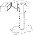
- FIG. 1is a schematic diagram showing the distal end of a trocar having an associated pressure sensor, the distal end placed in the abdominal cavity of a patient;
- FIGS. 2A and 2Bare schematic diagrams of the trocar of FIG. 1 at a first location corresponding to a position in which the trocar is at a low insufflator pressure and at a second location resulting from increased pressure supplied to the patient cavity;
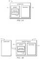
- FIGS. 3A and 3Bare block diagrams illustrating additional details of components of the system of FIG. 1 that may be used to effect pressure determination and resulting actions;
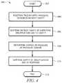
- FIG. 4is a flow chart illustrating a method that includes use of a pressure sensor associated with a trocar.
- the present disclosurerelates to a method for monitoring the change in height of the trocar using a pressure sensor.
- Small pressure sensorsare available in the marketplace that can measure absolute barometric pressures. The accuracy of these devices can be well less than 1 Pascal pressure. These pressure sensors have the ability to measure the relative changes in altitude of close to one inch.
- the relative height of the trocarcan be measured during insufflation of the cavity.
- pressurebuilds in the cavity, the abdominal wall begins to lift. The lifting of the abdominal wall slowly creates a pocket or cavity of CO2 gas. Once the cavity has risen to the desired height, the surgeon now has the required visibility to gain access to a target surgical site in the cavity.
- the surgeonhas a difficult time determining the optimized gas pressure to achieve the required cavity distention.
- the difficultyis due to a number of factors including the patient's cavity size, weight, location of target site, etc. Due to this difficulty, the surgeon will often over-pressurize the patient. This over-pressurization can cause a variety of issues including increased CO2 adsorption and reduced blood flow to the peritoneal wall.
- Example embodimentsare best understood by referring to FIGS. 1 through 4B of the drawings and the description below, like numerals being used for like and corresponding parts of the various drawings.
- FIG. 1is a schematic diagram showing the distal end 24 of a trocar 14 placed in the abdominal cavity 20 of a patient.
- an insufflator 10supplies insufflation gas through conduit 12 and trocar 14 to patient cavity 20 .
- Trocar 14allows insertion of a surgical instrument 28 into patient cavity 20 .
- Trocar 14has a pressure sensor 22 on or associated with the trocar 14 .
- the locationcan be anywhere in or on trocar 14 or associated with trocar 14 such that vertical movement of trocar 14 results in vertical movement of pressure sensor 22 ; however, as described in greater detail below, in one embodiment pressure sensor is located on the exterior of trocar 14 such that changes of pressure within trocar 14 due to supply of insufflation fluid to patient cavity 20 do not affect the pressure measured by pressure sensor 22 .
- pressure sensor 22is an absolute pressure sensor that can measure pressure in patient cavity 20 (if disposed within patient cavity 20 ) or in the room in which the associated operation is taking place.
- Pressure sensor 22is coupled to insufflator 10 through any suitable technique, including a wired connection 25 or a wireless connection. Pressure sensor supplies pressure data to insufflator 10 . Insufflator 10 uses this pressure data to determine the change in height of trocar 14 relative to changes in cavity pressure and thus the resulting change in height of patient cavity 20 , as described in greater detail below in conjunction with FIGS. 2A through 4 . Based upon this information, insufflator 10 (or other associated device) can determine the optimum, or a close approximation thereof, of the best pressure for the laparoscopic surgery and as a result control the pressure within patient cavity by controlling the pressure of the insufflation gas supplied by insufflator through tube 12 . Additional details of certain portions of FIG. 1 are described below.
- Insufflator 10may be any suitable source of insufflation gas at any suitable pressure. Insufflator may adjust the supply of insufflation gas to patient cavity 20 by adjusting the pressure and/or the volume of insufflation gas supplied to patient cavity 20 . Insufflator may include appropriate hardware and/or software for processing signals indicative of pressures measured by pressure sensor 22 and processing such signals to convert them into useful information, such as converting them into pressures, heights, and/or other data that can be used control the flow of insufflation gas to patient cavity 20 , and further for processing such data to determine a desired pressure and/or volume of insufflation fluid supplied to patient cavity 20 and for effecting such delivery.
- Conduit 12may be any suitable conduit for providing an insufflation gas to a portion of a trocar.
- An example of conduit 12includes flexible PVC tubing.
- the insufflation gasmay be any suitable gas used for insufflation purposes. In one example, insufflation case is carbon dioxide.
- Trocar 14may be any suitable trocar through which insufflation fluid may be supplied to a patient cavity. Examples of one or more trocars are provided in U.S. Pat. No. 8,715,219 (the '219 Patent), U.S. Pat. No. 7,285,112 (the '112 Patent), and U.S. Pat. No. 8,216,189 (the '189 Patent), which are hereby incorporated by reference as if fully set forth herein. Trocar 14 may be have a single lumen or may be formed with an inner tubular lumen and an outer tubular lumen such that insufflation fluid may be supplied through one of the lumens but not the other.
- any of the lumensmay be divided into multiple, separate chambers, such that fluid in one chamber does not enter the other chamber.
- Examples of the above multiple lumens and multiple chambered trocarsare described in U.S. application Ser. No. 14/792,873, entitled “Method and System for Gas Maintenance to a Body Cavity Using a Trocar,” which is hereby incorporated by reference.
- Trocar 14may be open or closed at the distal end 24 , as the application of the trocar would allow.
- Pressure sensor 22may be any sensor capable of sensing pressure or a change in pressure. Pressure sensor 22 may measure absolute pressure or a pressure relative to some other pressure. In some embodiments, pressure sensor 22 is an absolute sensor that can measure pressure in patient cavity 20 (if disposed within patient cavity 20 ) or in the room in which the associated operation is taking place. In particular embodiments, pressure sensor 22 can measure absolute barometric pressures with an accuracy of less than 1 Pascal pressure and therefore have the ability to measure the relative changes in altitude of close to one inch. Such pressure sensors are readily available in the marketplace.
- FIG. 2Ais a schematic diagram of trocar 14 at a first location (denoted by 14 a and in solid lines) corresponding to a position in which the trocar 14 is at a low insufflator pressure and at a second location (denoted by 14 b and in dotted lines) resulting from increased pressure supplied to the patient cavity.
- FIG. 2Bis analogous to FIG. 2A , but illustrates both trocars 14 a and 14 b separated horizontally in space in the drawing for clarity of illustration, but additionally corresponding to the same horizontal position, identified by reference numeral 34 in FIG. 2A . It should be appreciated, however, that trocar 14 may move both vertically and horizontally due to distention of the patient cavity.
- trocar 14 a in solid linescorresponds to trocar 14 at a first vertical location. This first location may correspond to a position in which patient cavity 20 a is not distended at all or may correspond to a location in which patient cavity 20 a is partially distended.
- Trocar 14 b in dotted linescorresponds to trocar 14 at a second vertical location after some distention of patient cavity, shown by dotted line 20 b .
- the altitude “Ha” of pressure sensor 22 a on trocar 14 a relative to an arbitrary reference point 30is indicated by reference numeral 26 .
- a corresponding altitude “Hb” of pressure sensor 22 b of trocar 14 b relative to reference point 30is indicated by reference numeral 28 .
- the difference between these two altitudes “delta H”is indicated by reference numeral 32 .
- pressure sensor 22is sensitive to changes in altitude and thus can provide a good indication of the relative change in altitude of pressure sensor 22 from a first altitude to a second altitude, which is indicative of the amount of distension of patient cavity 20 (indicated by dotted line 20 b ). Due to the elasticity of the patient's cavity 20 , higher pressures will start to lift the patient cavity less and less. Based upon the height increase (delta H) versus the cavity pressure a curve can be determined to optimized pressure, in one embodiment. In other embodiments, using this resulting change in pressure or change in altitude may be used in other manners to control insufflation gas supplied to patient cavity or to assist in other decisions, as described in greater detail below.
- FIGS. 3A and 3Bare block diagrams illustrating additional details of components of the system of FIG. 1 that may be used to effect pressure determination and resulting actions.
- FIG. 3Aillustrates additional details of insufflator 10 , according to one embodiment.
- insufflator 10includes a memory 40 and a processor 42 communicatively coupled to the memory 40 .
- Memory 40stores a pressure application 44 , which may include logic for effecting pressure and altitude determination as described with respect to the other FIGURES as well as control of the supply of insufflation gas to patient cavity 20 .
- FIG. 3Billustrates an alternative embodiment of the system of FIG.
- an insufflator 110includes only standard features and is communicatively coupled through a connection 114 to a pressure module 112 .
- Pressure module 112includes components analogous to those described with respect to FIG. 3A , including a memory 140 and processor 142 , but are included in this stand-alone pressure module.
- Connection 114 between insufflator 110 and pressure module 112may be wired or wireless. It will be understood that although a software-based system is illustrated in FIGS. 3A and 3B the logic described herein could instead be implemented through hardware circuits or a combination of hardware and software.
- FIG. 4is a flow chart illustrating a method 200 that includes use of a pressure sensor associated with a trocar.
- the methodmay utilize structural items such as those described in FIGS. 1A through 3B or may use alternative structural items.
- Computational steps described belowmay be performed by any suitable computation device, including insufflator 10 and pressure module 112 , for example.
- the methodbegins at step 202 .
- a trocarsuch as trocar 14 , having a pressure sensor, such as pressure sensor 22 , in or on the trocar is positioned into a patient cavity, such as patient cavity 20 , such that distension of the patient cavity 20 causes an altitude of the pressure sensor to increase.
- the pressure sensormay be positioned on the exterior or interior of the trocar and may be located within or external to the patient cavity.
- the methodincludes distending the patient cavity by supplying an insufflation gas to the patient cavity, thereby increasing an altitude of the pressure sensor from a first altitude to a second altitude.
- an insufflation gasis supplied by an insufflator, such as insufflator 10 , through the associated trocar.
- the methodincludes determining a change in pressure at the pressure sensor resulting from increasing the altitude of the pressure sensor from the first altitude to the second altitude.
- determining a change in pressure at the pressure sensorresulting from increasing the altitude of the pressure sensor from the first altitude to the second altitude.
- such actionsmay be performed by a pressure control application associated with or part of insufflator 10 , or by other devices.
- the determination of the change in pressuremay be effected according to a variety of approaches. For example, in one embodiment, the atmospheric pressure at each altitude is measured and a difference is determined. As another example, the pressure difference may be determined by measuring a pressure at the first and second altitudes, which may or may not be a function of atmospheric pressure and may not be the same as atmospheric pressure, and then calculating a difference.
- the first altitudemay be an altitude of the pressure sensor after positioning the trocar into the patient cavity and prior to the supplying of insufflation gas to the patient cavity, or alternatively may be the altitude of pressure sensor after positioning the trocar into the patient cavity and after supplying some insufflation gas into the patient cavity.
- the methodincludes controlling the supply of insufflation gas to the patient cavity in response to the determined change in pressure resulting from increasing the altitude of the pressure sensor from the first altitude to the second altitude. This may include determining that the pressure or amount of insufflation gas supplied to the patent cavity may be reduced and/or determining that the patient cavity is sufficiently distended such that the pressure or amount of the insufflation gas supplied to the patient cavity may be reduced. Further, the change in altitude of the pressure sensor and/or the patient cavity may be assessed to determine that the patient cavity is sufficiently distended.
- the controlmay also include, in some embodiments, comparing the change in the first altitude and the second altitude with a pressure or change in pressure in the patient cavity and/or determining a ratio of the determined change in pressure resulting from increasing the altitude of the pressure sensor from the first altitude to the second altitude to a pressure or change in pressure within the patient cavity and basing a decision on the control of the insufflation gas based on that decision.
- the controlmay also include, in some embodiments, determining the change in altitude of the pressure sensor from the first altitude to the second altitude from the determined change in pressure, comparing the determined change in altitude with a pressure or change in pressure in the patient cavity, and controlling the supply of insufflation gas to the patient cavity in response to the comparison.
- Step 210may be omitted entirely, or, alternatively, replaced with merely determining a change in altitude from the first altitude to the second altitude or determining that the patient cavity is sufficiently distended for surgery. Also, step 210 may be replaced with controlling the supply of insufflation gas to the patient cavity based at least in part on the determined amount of distension of the patient cavity. Further, step 210 may be replaced with simply displaying a pressure setting at which a surgeon may set the pressure of the insufflation gas to be supplied to a patient cavity. This display may be on the insufflator or other device.
- the methodconcludes at step 212 .
- a method and systemhave been described that For example, in some embodiments, a method allows more accurate determination of the optimized gas pressure to achieve required cavity distention. This can avoid over-pressurization of the patient, which could cause a variety of issues including increased CO2 adsorption and reduced blood flow to the peritoneal wall.
Landscapes
- Health & Medical Sciences (AREA)
- Life Sciences & Earth Sciences (AREA)
- Surgery (AREA)
- Public Health (AREA)
- Animal Behavior & Ethology (AREA)
- Engineering & Computer Science (AREA)
- Biomedical Technology (AREA)
- Heart & Thoracic Surgery (AREA)
- Veterinary Medicine (AREA)
- General Health & Medical Sciences (AREA)
- Nuclear Medicine, Radiotherapy & Molecular Imaging (AREA)
- Molecular Biology (AREA)
- Medical Informatics (AREA)
- Pathology (AREA)
- Anesthesiology (AREA)
- Hematology (AREA)
- Surgical Instruments (AREA)
- Endoscopes (AREA)
Abstract
Description
Claims (16)
Priority Applications (2)
| Application Number | Priority Date | Filing Date | Title |
|---|---|---|---|
| US15/293,013US10835284B2 (en) | 2016-10-13 | 2016-10-13 | Method and system for controlling pressurization of a patient cavity using cavity distension measured by a pressure sensor of a trocar |
| PCT/US2017/056322WO2018071657A1 (en) | 2016-10-13 | 2017-10-12 | Method and system for controlling pressurization of a patient cavity using cavity distension measured by a pressure sensor of a trocar |
Applications Claiming Priority (1)
| Application Number | Priority Date | Filing Date | Title |
|---|---|---|---|
| US15/293,013US10835284B2 (en) | 2016-10-13 | 2016-10-13 | Method and system for controlling pressurization of a patient cavity using cavity distension measured by a pressure sensor of a trocar |
Publications (2)
| Publication Number | Publication Date |
|---|---|
| US20180103977A1 US20180103977A1 (en) | 2018-04-19 |
| US10835284B2true US10835284B2 (en) | 2020-11-17 |
Family
ID=61902929
Family Applications (1)
| Application Number | Title | Priority Date | Filing Date |
|---|---|---|---|
| US15/293,013Active2038-05-09US10835284B2 (en) | 2016-10-13 | 2016-10-13 | Method and system for controlling pressurization of a patient cavity using cavity distension measured by a pressure sensor of a trocar |
Country Status (2)
| Country | Link |
|---|---|
| US (1) | US10835284B2 (en) |
| WO (1) | WO2018071657A1 (en) |
Families Citing this family (5)
| Publication number | Priority date | Publication date | Assignee | Title |
|---|---|---|---|---|
| US11433190B2 (en) | 2017-05-31 | 2022-09-06 | Lexion Medical, Llc | Method and system for controlling pressurization of a patient cavity using a pressure sensor of a medical appliance |
| US20190000501A1 (en)* | 2017-07-03 | 2019-01-03 | Bryan Nowroozi | Systems, devices and methods for accessing a body |
| EP3659660B1 (en)* | 2018-11-30 | 2021-10-27 | Lexion Medical, LLC | System for controlling pressurization of a patient cavity using a pressure sensor of a medical appliance |
| US11541191B2 (en)* | 2019-05-09 | 2023-01-03 | Lexion Medical, Llc | Distributed flow path insufflation |
| US11957830B2 (en)* | 2019-10-03 | 2024-04-16 | Lexion Medical, Llc | Method and system for delivering insufflation fluid |
Citations (25)
| Publication number | Priority date | Publication date | Assignee | Title |
|---|---|---|---|---|
| US5147316A (en)* | 1990-11-19 | 1992-09-15 | Castillenti Thomas A | Laparoscopic trocar with self-locking port sleeve |
| US5209721A (en) | 1992-01-31 | 1993-05-11 | Wilk Peter J | Laparoscopic surgical device and related method |
| US5389077A (en) | 1993-03-03 | 1995-02-14 | Uresil Corporation | Minimally invasive body cavity penetrating instruments |
| US5423741A (en)* | 1993-05-28 | 1995-06-13 | Bei Medical Sytems, Inc. | Apparatus and method for the insufflation of gas into a body cavity |
| US5427114A (en) | 1993-08-19 | 1995-06-27 | Fiberoptic Sensor Technologies, Inc. | Dual pressure sensing catheter |
| US5676155A (en)* | 1994-06-13 | 1997-10-14 | Storz Endoskop Gmbh | Apparatus for insufflating gases |
| EP1109486A1 (en) | 1998-09-03 | 2001-06-27 | Ethicon, Inc. | System and method for controlled infusion and pressure monitoring |
| US6295877B1 (en) | 1999-03-30 | 2001-10-02 | A-Med Systems, Inc. | Pressure sensing cannula |
| US6299592B1 (en) | 1998-03-31 | 2001-10-09 | Northgate Technologies Inc. | Laparoscopic insufflator |
| US20040102733A1 (en) | 2002-11-21 | 2004-05-27 | Wendy Naimark | Minimally-invasive smart devices |
| US20050115043A1 (en) | 2003-11-28 | 2005-06-02 | Canon Kabushiki Kaisha | Remanufacturing method for process cartridge |
| US6905489B2 (en) | 2001-04-24 | 2005-06-14 | Northgate Technologies, Inc. | Laparoscopic insertion device |
| US7285112B2 (en) | 2003-04-08 | 2007-10-23 | Surgiquest, Incorporated | Gas flow trocar arrangement |
| US7722558B2 (en) | 2005-02-15 | 2010-05-25 | Ott Douglas E | Trocar sleeve for jet stream condition |
| US20100152664A1 (en)* | 2008-12-11 | 2010-06-17 | Tyco Healthcare Group Lp | Trocar entry incorporating an airbag |
| US20110218484A1 (en)* | 2010-03-02 | 2011-09-08 | Tyco Healthcare Group Lp | Internally pressurized medical devices |
| US8216189B2 (en) | 2003-04-08 | 2012-07-10 | Surgiquest, Inc. | Continuous gas flow trocar assembly |
| US20120184897A1 (en) | 2010-07-19 | 2012-07-19 | Minimally Invasive Devices, Llc | Integrated systems and methods for maintenance and management of an intra-abdominal gas environment during laparoscopic surgery |
| US20120245511A1 (en) | 2011-03-08 | 2012-09-27 | SurgiQuest, Inc | Trocar assembly with pneumatic sealing |
| WO2013011398A1 (en) | 2011-07-20 | 2013-01-24 | Koninklijke Philips Electronics N.V. | A method of enhancing the detectability of a height change with an air pressure sensor and a sensor unit for determining a height change. |
| US8715219B2 (en) | 2008-10-10 | 2014-05-06 | Surgiquest, Inc. | System and method for improved gas recirculation in surgical trocars with pneumatic sealing |
| US20150005698A1 (en)* | 2012-03-15 | 2015-01-01 | Terumo Kabushiki Kaisha | Applicator |
| EP2825840A1 (en) | 2012-03-13 | 2015-01-21 | Koninklijke Philips N.V. | Monitoring the change in height of a device using an air pressure sensor |
| US9138549B2 (en) | 2009-01-29 | 2015-09-22 | Mgb Endoskopische Geraete Gmbh Berlin | Insufflator |
| US20150290387A1 (en) | 2013-11-08 | 2015-10-15 | Bonvisi Ab | Device for irrigation and insufflation with blood pressure dependent pressure control |
- 2016
- 2016-10-13USUS15/293,013patent/US10835284B2/enactiveActive
- 2017
- 2017-10-12WOPCT/US2017/056322patent/WO2018071657A1/ennot_activeCeased
Patent Citations (26)
| Publication number | Priority date | Publication date | Assignee | Title |
|---|---|---|---|---|
| US5147316A (en)* | 1990-11-19 | 1992-09-15 | Castillenti Thomas A | Laparoscopic trocar with self-locking port sleeve |
| US5209721A (en) | 1992-01-31 | 1993-05-11 | Wilk Peter J | Laparoscopic surgical device and related method |
| US5389077A (en) | 1993-03-03 | 1995-02-14 | Uresil Corporation | Minimally invasive body cavity penetrating instruments |
| US5423741A (en)* | 1993-05-28 | 1995-06-13 | Bei Medical Sytems, Inc. | Apparatus and method for the insufflation of gas into a body cavity |
| US5427114A (en) | 1993-08-19 | 1995-06-27 | Fiberoptic Sensor Technologies, Inc. | Dual pressure sensing catheter |
| US5676155A (en)* | 1994-06-13 | 1997-10-14 | Storz Endoskop Gmbh | Apparatus for insufflating gases |
| US6299592B1 (en) | 1998-03-31 | 2001-10-09 | Northgate Technologies Inc. | Laparoscopic insufflator |
| EP1109486A1 (en) | 1998-09-03 | 2001-06-27 | Ethicon, Inc. | System and method for controlled infusion and pressure monitoring |
| US6295877B1 (en) | 1999-03-30 | 2001-10-02 | A-Med Systems, Inc. | Pressure sensing cannula |
| US6905489B2 (en) | 2001-04-24 | 2005-06-14 | Northgate Technologies, Inc. | Laparoscopic insertion device |
| US20040102733A1 (en) | 2002-11-21 | 2004-05-27 | Wendy Naimark | Minimally-invasive smart devices |
| US7285112B2 (en) | 2003-04-08 | 2007-10-23 | Surgiquest, Incorporated | Gas flow trocar arrangement |
| US8216189B2 (en) | 2003-04-08 | 2012-07-10 | Surgiquest, Inc. | Continuous gas flow trocar assembly |
| US20050115043A1 (en) | 2003-11-28 | 2005-06-02 | Canon Kabushiki Kaisha | Remanufacturing method for process cartridge |
| US7722558B2 (en) | 2005-02-15 | 2010-05-25 | Ott Douglas E | Trocar sleeve for jet stream condition |
| US8715219B2 (en) | 2008-10-10 | 2014-05-06 | Surgiquest, Inc. | System and method for improved gas recirculation in surgical trocars with pneumatic sealing |
| US8235940B2 (en) | 2008-12-11 | 2012-08-07 | Tyco Healthcare Group Lp | Trocar entry incorporating an airbag |
| US20100152664A1 (en)* | 2008-12-11 | 2010-06-17 | Tyco Healthcare Group Lp | Trocar entry incorporating an airbag |
| US9138549B2 (en) | 2009-01-29 | 2015-09-22 | Mgb Endoskopische Geraete Gmbh Berlin | Insufflator |
| US20110218484A1 (en)* | 2010-03-02 | 2011-09-08 | Tyco Healthcare Group Lp | Internally pressurized medical devices |
| US20120184897A1 (en) | 2010-07-19 | 2012-07-19 | Minimally Invasive Devices, Llc | Integrated systems and methods for maintenance and management of an intra-abdominal gas environment during laparoscopic surgery |
| US20120245511A1 (en) | 2011-03-08 | 2012-09-27 | SurgiQuest, Inc | Trocar assembly with pneumatic sealing |
| WO2013011398A1 (en) | 2011-07-20 | 2013-01-24 | Koninklijke Philips Electronics N.V. | A method of enhancing the detectability of a height change with an air pressure sensor and a sensor unit for determining a height change. |
| EP2825840A1 (en) | 2012-03-13 | 2015-01-21 | Koninklijke Philips N.V. | Monitoring the change in height of a device using an air pressure sensor |
| US20150005698A1 (en)* | 2012-03-15 | 2015-01-01 | Terumo Kabushiki Kaisha | Applicator |
| US20150290387A1 (en) | 2013-11-08 | 2015-10-15 | Bonvisi Ab | Device for irrigation and insufflation with blood pressure dependent pressure control |
Non-Patent Citations (5)
| Title |
|---|
| Dr. Asif Iqbal, et al.; Effects of Co2 Pneumoperitoneum in Patients Undergoing Short Laparoscopic Gynaecology Procedures: IOSR Journal of Dental and Medical Sciences; 2279-0861, vol. 15; Issue 6 Ver. VIII; pp. 11-15; www.iosrjournals.org, Jun. 2016. |
| PCT International Search Report; appl. No. PCT/US17/56322; 2 pages, dated Dec. 11, 2017. |
| PCT Written Opinion of the International Searching Authority; appl. No. PCT/US17/56322; 7 pages, dated Dec. 11, 2017. |
| Rawandale, Pav; Rawandale's Laparoscopic Port Placement Barometer; IN-MUM-2014-00059A; abstract; statement of invention; 7 pages, Jan. 31, 2014. |
| Sanaz Hariri Tabrizi, et al.; A Preliminary Study on the Use of an Automatic Trocar for LAparoscopic Surgery (ATLAS System); vol. 2, Issue 4; 6 pages, Dec. 2015. |
Also Published As
| Publication number | Publication date |
|---|---|
| WO2018071657A1 (en) | 2018-04-19 |
| US20180103977A1 (en) | 2018-04-19 |
Similar Documents
| Publication | Publication Date | Title |
|---|---|---|
| US10835284B2 (en) | Method and system for controlling pressurization of a patient cavity using cavity distension measured by a pressure sensor of a trocar | |
| US10238421B2 (en) | Method and system for gas maintenance to a body cavity using a trocar | |
| US20210338266A1 (en) | Method and system for measuring pressure in a body cavity using a trocar | |
| US11433190B2 (en) | Method and system for controlling pressurization of a patient cavity using a pressure sensor of a medical appliance | |
| US12415047B2 (en) | Method and system for measuring pressure in a body cavity | |
| JP2008531096A (en) | Enteral feed catheter, computer system and computer program for operating the feed catheter | |
| EP3409222B1 (en) | System for controlling pressurization of a patient cavity using a pressure sensor in a trocar | |
| US20240148407A1 (en) | Method and System for Gas Maintenance to a Body Cavity Using a Trocar | |
| US20230132683A1 (en) | Distributed flow path insufflation | |
| EP4027918B1 (en) | A modular system for monitoring and controlling the homeostasis in cavities | |
| JPWO2016031272A1 (en) | Pneumoperitoneum | |
| US20190307316A1 (en) | A medical device having a gas path apparatus | |
| US10357283B2 (en) | Method and system for determining pressure and flow restrictions in a body cavity using a trocar | |
| US20250276137A1 (en) | Medical pump for endoscopy | |
| EP3659660B1 (en) | System for controlling pressurization of a patient cavity using a pressure sensor of a medical appliance | |
| JP4776914B2 (en) | Air supply device | |
| US20250090772A1 (en) | A method and an insufflator for determining a value of a volume of insufflating gas to be drawn from an insufflated cavity during evacuating of the cavity | |
| Chopra et al. | Research Article Pressure Measurement Techniques for Abdominal Hypertension: Conclusions from an Experimental Model |
Legal Events
| Date | Code | Title | Description |
|---|---|---|---|
| AS | Assignment | Owner name:LEXION MEDICAL, LLC, MINNESOTA Free format text:ASSIGNMENT OF ASSIGNORS INTEREST;ASSIGNORS:GEISZ, CARL M.;OTT, DOUGLAS E.;SIGNING DATES FROM 20160829 TO 20160923;REEL/FRAME:040010/0099 | |
| STPP | Information on status: patent application and granting procedure in general | Free format text:RESPONSE TO NON-FINAL OFFICE ACTION ENTERED AND FORWARDED TO EXAMINER | |
| STPP | Information on status: patent application and granting procedure in general | Free format text:NON FINAL ACTION MAILED | |
| STPP | Information on status: patent application and granting procedure in general | Free format text:RESPONSE TO NON-FINAL OFFICE ACTION ENTERED AND FORWARDED TO EXAMINER | |
| STPP | Information on status: patent application and granting procedure in general | Free format text:FINAL REJECTION MAILED | |
| STPP | Information on status: patent application and granting procedure in general | Free format text:NON FINAL ACTION MAILED | |
| STPP | Information on status: patent application and granting procedure in general | Free format text:NOTICE OF ALLOWANCE MAILED -- APPLICATION RECEIVED IN OFFICE OF PUBLICATIONS | |
| STPP | Information on status: patent application and granting procedure in general | Free format text:PUBLICATIONS -- ISSUE FEE PAYMENT RECEIVED | |
| STPP | Information on status: patent application and granting procedure in general | Free format text:PUBLICATIONS -- ISSUE FEE PAYMENT VERIFIED | |
| STCF | Information on status: patent grant | Free format text:PATENTED CASE | |
| MAFP | Maintenance fee payment | Free format text:PAYMENT OF MAINTENANCE FEE, 4TH YR, SMALL ENTITY (ORIGINAL EVENT CODE: M2551); ENTITY STATUS OF PATENT OWNER: SMALL ENTITY Year of fee payment:4 |