US10834855B2 - Integrated make-up air system in 100% air recirculation system - Google Patents
Integrated make-up air system in 100% air recirculation systemDownload PDFInfo
- Publication number
- US10834855B2 US10834855B2US16/067,446US201616067446AUS10834855B2US 10834855 B2US10834855 B2US 10834855B2US 201616067446 AUS201616067446 AUS 201616067446AUS 10834855 B2US10834855 B2US 10834855B2
- Authority
- US
- United States
- Prior art keywords
- air
- housing
- make
- process air
- coil
- Prior art date
- Legal status (The legal status is an assumption and is not a legal conclusion. Google has not performed a legal analysis and makes no representation as to the accuracy of the status listed.)
- Active, expires
Links
Images


Classifications
- H—ELECTRICITY
- H05—ELECTRIC TECHNIQUES NOT OTHERWISE PROVIDED FOR
- H05K—PRINTED CIRCUITS; CASINGS OR CONSTRUCTIONAL DETAILS OF ELECTRIC APPARATUS; MANUFACTURE OF ASSEMBLAGES OF ELECTRICAL COMPONENTS
- H05K7/00—Constructional details common to different types of electric apparatus
- H05K7/20—Modifications to facilitate cooling, ventilating, or heating
- H05K7/20709—Modifications to facilitate cooling, ventilating, or heating for server racks or cabinets; for data centers, e.g. 19-inch computer racks
- H05K7/20718—Forced ventilation of a gaseous coolant
- H05K7/20745—Forced ventilation of a gaseous coolant within rooms for removing heat from cabinets, e.g. by air conditioning device
- F—MECHANICAL ENGINEERING; LIGHTING; HEATING; WEAPONS; BLASTING
- F24—HEATING; RANGES; VENTILATING
- F24F—AIR-CONDITIONING; AIR-HUMIDIFICATION; VENTILATION; USE OF AIR CURRENTS FOR SCREENING
- F24F12/00—Use of energy recovery systems in air conditioning, ventilation or screening
- F24F12/001—Use of energy recovery systems in air conditioning, ventilation or screening with heat-exchange between supplied and exhausted air
- F24F12/006—Use of energy recovery systems in air conditioning, ventilation or screening with heat-exchange between supplied and exhausted air using an air-to-air heat exchanger
- F—MECHANICAL ENGINEERING; LIGHTING; HEATING; WEAPONS; BLASTING
- F24—HEATING; RANGES; VENTILATING
- F24F—AIR-CONDITIONING; AIR-HUMIDIFICATION; VENTILATION; USE OF AIR CURRENTS FOR SCREENING
- F24F13/00—Details common to, or for air-conditioning, air-humidification, ventilation or use of air currents for screening
- F24F13/30—Arrangement or mounting of heat-exchangers
- F—MECHANICAL ENGINEERING; LIGHTING; HEATING; WEAPONS; BLASTING
- F24—HEATING; RANGES; VENTILATING
- F24F—AIR-CONDITIONING; AIR-HUMIDIFICATION; VENTILATION; USE OF AIR CURRENTS FOR SCREENING
- F24F3/00—Air-conditioning systems in which conditioned primary air is supplied from one or more central stations to distributing units in the rooms or spaces where it may receive secondary treatment; Apparatus specially designed for such systems
- F24F3/044—Systems in which all treatment is given in the central station, i.e. all-air systems
- F—MECHANICAL ENGINEERING; LIGHTING; HEATING; WEAPONS; BLASTING
- F24—HEATING; RANGES; VENTILATING
- F24F—AIR-CONDITIONING; AIR-HUMIDIFICATION; VENTILATION; USE OF AIR CURRENTS FOR SCREENING
- F24F6/00—Air-humidification, e.g. cooling by humidification
- F24F6/02—Air-humidification, e.g. cooling by humidification by evaporation of water in the air
- H—ELECTRICITY
- H05—ELECTRIC TECHNIQUES NOT OTHERWISE PROVIDED FOR
- H05K—PRINTED CIRCUITS; CASINGS OR CONSTRUCTIONAL DETAILS OF ELECTRIC APPARATUS; MANUFACTURE OF ASSEMBLAGES OF ELECTRICAL COMPONENTS
- H05K7/00—Constructional details common to different types of electric apparatus
- H05K7/20—Modifications to facilitate cooling, ventilating, or heating
- H05K7/20709—Modifications to facilitate cooling, ventilating, or heating for server racks or cabinets; for data centers, e.g. 19-inch computer racks
- H05K7/208—Liquid cooling with phase change
- H05K7/20827—Liquid cooling with phase change within rooms for removing heat from cabinets, e.g. air conditioning devices
- F—MECHANICAL ENGINEERING; LIGHTING; HEATING; WEAPONS; BLASTING
- F24—HEATING; RANGES; VENTILATING
- F24F—AIR-CONDITIONING; AIR-HUMIDIFICATION; VENTILATION; USE OF AIR CURRENTS FOR SCREENING
- F24F2203/00—Devices or apparatus used for air treatment
- F24F2203/10—Rotary wheel
- F24F2203/104—Heat exchanger wheel
- Y—GENERAL TAGGING OF NEW TECHNOLOGICAL DEVELOPMENTS; GENERAL TAGGING OF CROSS-SECTIONAL TECHNOLOGIES SPANNING OVER SEVERAL SECTIONS OF THE IPC; TECHNICAL SUBJECTS COVERED BY FORMER USPC CROSS-REFERENCE ART COLLECTIONS [XRACs] AND DIGESTS
- Y02—TECHNOLOGIES OR APPLICATIONS FOR MITIGATION OR ADAPTATION AGAINST CLIMATE CHANGE
- Y02B—CLIMATE CHANGE MITIGATION TECHNOLOGIES RELATED TO BUILDINGS, e.g. HOUSING, HOUSE APPLIANCES OR RELATED END-USER APPLICATIONS
- Y02B30/00—Energy efficient heating, ventilation or air conditioning [HVAC]
- Y02B30/56—Heat recovery units
- Y02B30/563—
Definitions
- a data centerusually consists of computers and associated components operating 24 hours a day, 7 days a week.
- the electrical components in data centersproduce a lot of heat, which needs to be removed from the space.
- Air-conditioning systems in data centerscan consume as much as 40% of the total energy.
- An indirect evaporative cooling (IDEC) unitis an example of a 100% air recirculation system. While the IDEC unit can provide significant energy savings, it may be necessary to provide a make-up air unit in order to meet ventilation requirements for the enclosed space.
- Make-up air unitsmay be required to periodically or continuously provide fresh outdoor air to the enclosed space.
- a particular industrymay have standard requirements for make-up or replenishment air.
- Data centersare an example of an industry having such requirements. For example, a data center may be required to provide 0.5 CFM/sq ft of fresh outdoor air to the process air contained in the data center. For a data center sized at 10,000 square feet, the exemplary requirement translates to providing 500 cubic feet per minute of fresh outdoor air to the data center.
- a make-up air unitcan filter the fresh outdoor air and condition the outdoor air based on the particular conditions of the outdoor air, which may require heating or cooling and humidification or dehumidification.
- the make-up air unitcan be separate and external to the 100% air recirculation system.
- the make-up air unitcan be placed outside the enclosed space (on the roof or in a parking lot) or inside the enclosed space; but in both cases, the make-up air unit is separate from the 100% air recirculation system.
- the make-up air unitcan be an add-on module attached or otherwise connected to an external portion of the 100% air recirculation system.
- An external make-up air unitcan increase an overall footprint of the air conditioning system.
- the make-up air unitcan require additional components, such as compressors, condensers or fans, which can occupy a significant amount of space and consume a significant amount of energy.
- the process air from the enclosed spacesuch as a data center
- the process aircontinues to be circulated back to the data center, it can be challenging to efficiently maintain a humidity level of the process air, particularly under cold temperature conditions.
- the present inventorsrecognize, among other things, an opportunity for improved efficiency in supplying make-up or replenishment air to the process air in an enclosed space which is conditioned using a 100% air recirculation system.
- the present inventorsfurther recognize, among other things, improved efficiency in maintaining humidity levels of the process air as it continues to be circulated through the air conditioning system and back to the enclosed space.
- non-limiting examplespertain generally, but not by way of limitation, to systems and methods of conditioning air in an enclosed space, such as a commercial or residential building, while efficiently providing make-up or replenishment air to the enclosed space.
- the following non-limiting examplesare provided to further illustrate the systems and methods disclosed herein.
- Examples according to the present applicationcan include 100% air recirculation systems and methods that condition air from an enclosed space, such as, for example, a data center.
- the air conditioning systemcan include a housing formed by exterior walls that at least partially enclose components inside the housing. Essentially all of the air from the enclosed space (process air) can pass through the system and scavenger air can be used to condition the process air with an air-to-air heat exchanger (AAHX) arranged inside the housing. For cooling applications, such as a data center, the scavenger air can indirectly and sensibly cool the warm process air.
- the systemcan include an integral make-up air (MUA) unit arranged inside the housing, in the flow path of process air downstream of the AAHX.
- the make-up air unitcan deliver make-up or replenishment air, from outside, into the flow path of process air. The replenishment air can mix with the process air after the process air exits the AAHX and before the process air is returned to the enclosed space.
- the make-up air unitcan be located in the process air flow path, downstream of the AAHX and upstream of the process air outlet.
- the make-up air unitcan include a damper that can be selectively opened and closed to allow outside air to enter the housing as make-up or replenishment air for the enclosed space.
- the make-up air unitcan include a filter to filter the replenishment air prior to adding it to the process air.
- the make-up air unitcan be configured to selectively warm or cool the replenishment air.
- the make-up air unitcan include a DX coil to selectively cool and dehumidify the replenishment air before the replenishment air enters the flow path of process air. The DX coil can be selectively used depending on the outdoor air conditions.
- the make-up air unitcan include a heating device to selectively heat the replenishment air before the replenishment air enters the flow path of process air.
- the make-up air unitcan include a DX coil and a heating device, and one of the DX coil or the heating device can be selectively turned on depending on the outdoor air conditions or the needs for warming or cooling the air in the enclosed space.
- a humidifiercan be arranged inside the housing between the process air inlet and the AAHX, and the humidifier can selectively humidify a portion of the process air.
- the humidifiercan be located in other positions between the process air inlet and outlet. If the outdoor air temperature is cool but the air is dry, the humidifier can be used to add humidity to the overall process air.
- a combination of the make-up air unit and the humidifiercan provide an integral make-up or replenishment air system.
- the make-up air unit and the humidifiercan work in combination to help in maintaining a humidity level, as well as providing fresh, replenishment air, for the process air being returned to the enclosed space as cold aisle supply air.
- Examples according to the present applicationin which an integral make-up air system can be located inside the housing of the air conditioning system, can provide benefits as compared to an external unit. Because the make-up air system can be contained within the housing of the air conditioning system, the make-up air system does not increase an overall footprint of the air conditioning system. Components of the make-up air system, such as for example, compressors or condensers used in conjunction with the make-up air DX coil, can be physically located in a shared space with similar components used for other parts of the air conditioning system.
- the air conditioning systemcan include a DX coil located in the process air stream downstream of the AAHX to provide additional cooling to the process air, and a condenser for the make-up air DX coil can be disposed generally adjacent to a condenser coil for the main DX coil.
- the integral make-up air systemcan efficiently use the space within the housing of the air conditioning system by grouping components of the make-up air system with similar components included with the air conditioning system.
- one or more fans used for the condenser of the main DX coilcan also be used for the condenser of the make-up air DX coil. This can contribute to energy savings for the air conditioning system, as compared to an air conditioning system having an external make-up air system.
- a make-up air systemcan include a DX coil located inside the housing of the air conditioning system for cooling and dehumidifying the replenishment air, before it is added to the process air stream, and an external condenser unit located outside of the housing.
- the condenser unitcan include a condenser coil in fluid communication with the make-up air DX coil.
- the condenser unitcan be attached to the exterior of the housing.
- an integral make-up air systemin which an integral make-up air system can include a humidifier in the process air stream, can provide additional energy savings as compared to an external make-up air system.
- cooling of the process airis required year round. If the outdoor air is cool, it would be beneficial to add the cool air to the process air as replenishment air; however, the outdoor air is also dry.
- existing external make-up air systemscan heat up the outdoor air in order to provide humidification, and then supply the humidified replenishment air at a moderate temperature. As a result, a significant amount of energy can be used to heat and humidify the replenishment air.
- the integral make-up air system disclosed hereincan add cold, dry replenishment air directly into the process air stream.
- the humidifieralso located in the process air stream, can selectively provide humidification to all or a portion of the process air stream.
- the humidifiercan be an evaporative cooler and the humidifier can also help with the cooling load of the overall system in addition to providing humidification.
- the replenishment air and the process airmix together at some location between the process air inlet and outlet, and once combined, provide return air for the enclosed space at a desired temperature and humidity level, using less energy overall compared to the external make-up air system described above.
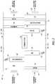
- FIG. 1is a schematic of an example air-conditioning system with an integrated make-up air system in accordance with the present patent application.
- FIG. 2is a schematic of an example air-conditioning system with an integrated make-up air system in accordance with the present patent application.
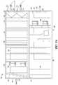
- FIG. 3Ais a side view of an air-conditioning system with an integrated make-up air system in accordance with the present patent application.
- FIG. 3Bis a top view of a top portion of the system in FIG. 3A .
- FIG. 3Cis a top view of a bottom portion of the system in FIG. 3A .
- FIG. 3Dis a top view of a bottom portion of an example air-conditioning system with an integrated make-up air system in accordance with the present patent application.
- FIG. 4is a schematic of an example air-conditioning system with an integrated make-up air system in accordance with the present patent application.
- FIG. 5Ais a side view of an air-conditioning system with an integrated make-up air system in accordance with the present patent application.
- FIG. 5Bis a top view of upper sections of the delivery system in FIG. 5A .
- FIG. 5Cis a top view of bottom sections of the delivery system in FIG. 5A .
- FIG. 6is a top view of a top portion of an example air-conditioning system with an integrated make-up air system in accordance with the present patent application.
- an air conditioning systemcan include a housing formed by exterior walls that at least partially enclose components inside the housing.
- An air-to-air heat exchanger (AAHX)can be arranged inside the housing in a flow path of process air and in a flow path of scavenger air.
- the systemcan include an integral make-up air (MUA) unit arranged inside the housing, in the flow path of process air downstream of the AAHX.
- the make-up air unitcan deliver make-up or replenishment air, from outside, into the flow path of process air, after the process air exits the AAHX and before the process air is returned to the enclosed space.
- the make-up air unitcan include at least one heating or cooling device to condition the replenishment air.
- the make-up air unitcan include a DX coil to selectively reduce a temperature of the replenishment air and dehumidify the replenishment air prior to it entering into the flow path of process air.
- the make-up air unitcan include a heating device to selectively increase a temperature of the replenishment air prior to it entering into the flow path of process air.
- a humidifiercan be arranged inside the housing, in the flow path of process air upstream of the AAHX, and can be configured to selectively humidify a portion of the process air.
- the combination of the make-up air unit and the humidifiercan provide an integral make-up or replenishment air system.
- the design of an integral make-up air system inside the housing of the air conditioning systemcan provide benefits as compared to an external unit. This is described in further detail below.
- FIG. 1depicts an example air-conditioning system 100 , which can be configured as a roof-top system or end-on delivery system (for example, mounted to a side wall) for conditioning air from an enclosed space.
- the system 100can include a housing 102 which can be formed by exterior walls that at least partially enclose the components located inside the housing 102 .
- Such componentscan include an air to air heat exchanger (AAHX) 104 , a humidifier 106 and a make-up air (MUA) unit 108 .
- AAHXair to air heat exchanger
- UOAmake-up air
- the housing 102can be configured as a two-level unit in which a scavenger air stream flows through a top level 110 and a process air stream flows through a bottom level 112 .
- the scavenger air streamcan enter the top level 110 through a scavenger air inlet 114 and can exit the top level 110 through a scavenger air outlet 116 .
- the process air streamfrom the enclosed space (a data center, for example), can enter the bottom level 112 at a process air inlet 118 as hot aisle return air and can exit the bottom level 112 at a process air outlet 120 as cold aisle supply air.
- the scavenger air inlet 114 and outlet 116as well as the process air inlet 118 and outlet 120 , can be configured as dampers such that the inlets and outlets can be selectively open or shut to allow or prevent air flow.
- the AAHX 104can be arranged at least partially in the top level 110 and at least partially in the bottom level 112 such that the scavenger air and the process air pass through the AAHX 104 .
- the scavenger air flow path and the process air flow pathcan remain separate from one another in the housing 102 .
- the scavenger air and process air flow pathscan be in opposite directions.
- the data center or process aircan be conditioned in the AAHX 104 using the scavenger air.
- the AAHX 104can include, but is not limited to, a sensible wheel or a counter-flow flat plate heat exchanger.
- Other cooling componentsincluding those described herein in reference to other examples of air conditioning systems, can be included with the AAHX 104 in the system 100 , although not shown in FIG. 1 .
- the system 100is an example of an air conditioning system having 100% air recirculation. Essentially all of the hot aisle return air that enters the bottom level 112 can be returned to the data center, or other enclosed space, as cold aisle supply air. It is recognized that some process air may be lost, for example, to leakage in the AAHX 104 . Although the present application focuses on a data center as the enclosed space, the systems and methods disclosed herein for conditioning air can be used in other examples of enclosed spaces. Because the data center is always producing heat, the air conditioning system is used year-round in that application to cool the process air from the data center.
- the air conditioning system 100can be used to provide heating, or heating and cooling, depending on the outdoor air conditions.
- the air conditioning systemcan thus include additional components not shown and described herein to provide heating/cooling and humidification/dehumidification capabilities.
- the make-up air unit 108can be located in the bottom level 112 in the process air flow path, downstream of the AAHX 104 and upstream of the process air outlet 120 .
- the make-up air unit 108can include an air inlet 122 that can be selectively opened and closed to allow outside air to enter the housing 102 as make-up or replenishment air for the enclosed space.
- the humidifier 106can be located in the bottom level 112 in the process air flow path, downstream of the process air inlet 118 and upstream of the AAXH 104 .
- Outside air that enters the housing 102 through the make-up air unit 108can be essentially the same source of air that is defined as scavenger air that passes through the top level 110 of the housing 102 , opposite to the process air.
- scavenger airthe outside air used to cool the process air
- refplenishment airfresh air or make-up air that is added to the process air
- the make-up air unit 108can be configured to deliver replenishment air into the process air flow path such that replenishment air can be continuously or periodically added to the process air being returned to the enclosed space as cold aisle supply air.
- the make-up air unit 108can include a filter to filter the replenishment air prior to introducing the replenishment air into the process air stream.
- the make-up air unit 108can include at least one heating or cooling device to condition the replenishment air prior to introducing the replenishment air into the process air stream.
- the make-up air unitcan include a DX coil (see FIG. 3C ) to cool and dehumidify the replenishment air prior to the replenishment air entering into the flow path of the process air in the bottom level 112 .
- the DX coil of the make-up air unit 108can be selectively used depending on the outdoor air conditions. If the outdoor air temperature is cool, the DX coil may not be needed since, in that case, the outdoor air enters the housing 102 at a temperature appropriate for being supplied to the enclosed space as cold aisle supply air. In some examples, the outdoor air temperature can be cool but the outdoor air can be dry, and the humidifier 106 can be used to add humidity to the overall process air, as described below. In an example, the make-up air unit 108 can include a heating device (see FIG. 3D ), in addition to or as an alternative to the DX coil, to warm the replenishment air prior to introducing it into the process air stream.
- a heating devicesee FIG. 3D
- the make-up air unit 108does not increase an overall footprint of the air conditioning system 100 . Additional details about the make-up air unit 108 are described further below in reference to FIGS. 3A-3C .
- the humidifier 106can be located in the flow path of the process air at a location between the process air inlet 118 and the AAHX 104 . As described below, the humidifier 106 can be placed in other locations in the process air stream within the housing 102 .
- the humidifier 106can be used when the outdoor air temperature is cold, for example, in the winter, to humidify the process air prior to passing the process air through the AAHX 104 .
- the humidifier 106can help in maintaining a humidity level (or range) for the process air, even when the outside air is cold and dry.
- the process air entering the humidifier 106can be very warm and have low relative humidity, since it has come from the data center or other enclosed space. Thus the process air has good potential for humidification at this location in the housing 102 .
- a small portion of the process air flowing through the housing 102can be directed through the humidifier 106 and the remaining portion of the process air can bypass the humidifier 106 .
- Damperscan be used to modulate the flow of process air through the humidifier 106 and minimize pressure drop while providing an appropriate amount of humidification. This is described below in reference to systems 300 and 500 . (See, for example, FIGS. 3B and 5C .) If the humidifier 106 is not needed (for example, during summer when air is warm and humid), dampers or other types of bypass features can be used such that the process air does not pass through the humidifier 106 . Thus the humidifier 106 can be protected when it is not needed, and minimize pressure drop.
- the humidifier 106is shown in FIG. 1 located between the process air inlet 118 and the AAHX 104 . In other examples, the humidifier 106 can be located between the AAHX 104 and the process air outlet 120 . The humidifier 106 can be located in the process air flow path at any position between the process air inlet 118 and the process air outlet 120 . In an example, the humidifier 106 can be a small direct evaporative cooler (DEC) that can cool a portion of the process air through an evaporative process. In other examples, the humidifier 106 can be any type of humidifier, such as, for example, a steam humidifier.
- DECdirect evaporative cooler
- the humidifier 106is described herein separately from the make-up air unit 108 ; however, it is recognized that the humidifier 106 and the make-up air unit 108 can be considered to collectively function as a make-up or replenishment air system for the air conditioning system 100 .
- a make-up air systemis external to the air conditioning system.
- the make-up air systemis integral to the air conditioning system and can include the make-up air unit 108 and the humidifier 106 . Similar functions of an external make-up air system can be achieved through the distribution of one or more components that can be located inside the housing 102 of the air conditioning system 100 .
- the humidifier 106can be placed within the flow path of the process air, upstream of the AAHX 104 , to maintain or increase a humidity level of the process air.
- the make-up air unit 108can be placed within the flow path of the process air, downstream of the AAHX 104 , to add fresh, cool air into the process air flow path before the process air is returned to the enclosed space.
- the make-up air unit 108 and the humidifier 106can help in maintaining a humidity level (or range), as well as providing fresh, replenishment air, for the cold aisle supply air returned to the enclosed space.
- the make-up air unit 108 and the humidifier 106can, in combination, maintain a humidity level for the process air.
- the DX coil of the make-up air unit 108can be running such that the replenishment air entering the system 100 from outside can be cooled and dehumidified prior to being added to the process air stream.
- the humidifier 106can be off or bypassed since it may be unnecessary to further humidify the process air.
- the DX coil of the make-up air unit 108can be turned off since the replenishment air is already cool. However, the outdoor air can be dry.
- the humidifier 106can be used to add humidity to the process air stream.
- the replenishment airmixes with the process air stream downstream of the humidifier 106 and the humidity levels of each can balance with each other to reach a target humidity level or range for the process air stream being returned to the enclosed space.
- the combination of the make-up air unit 108 and the humidifier 106can be used to reach and maintain the target humidity value or range.
- the outdoor aircan be added to the process air stream (via the make-up air unit 108 ) even if the outdoor air is dry. This can eliminate the step of heating and humidifying the outdoor air, as is done in existing external make-up air systems, prior to adding the outdoor air as replenishment air. Elimination of this step can result in energy savings.
- the make-up air unit 108can be used independent of the humidifier 106 to provide replenishment air to the cold aisle supply air.
- the humidifier 106is not required in the system 100 , or in the other air conditioning systems shown and described herein. It is recognized that the humidifier 106 can be used independent of the make-up air unit 108 to humidify or maintain a humidity level of the process air from the data center or other enclosed space.
- the make-up air unit 108is not required in the system 100 , or in the other air conditioning systems shown and described herein.
- FIG. 2depicts an example air conditioning system 200 that can be similar to the system 100 of FIG. 1 .
- the system 200can include a housing 202 defined by exterior walls that at least partially enclose the components of the system 200 inside the housing 202 .
- the system 200can include a sensible wheel 203 , although it is recognized that another type of AAHX can be used in place or in addition to the sensible wheel of the system 200 .
- the sensible wheel 203can be arranged horizontally.
- the housing 202can be split into a first side portion 209 and a second side portion 211 .
- the first side portion 209can include a top level 210 A and a bottom level 212 A.
- the second side portion 211can include a top level 210 B and a bottom level 212 B.
- the flow paths of the scavenger and process air in the housing 202can be different, as compared to the flow paths in the housing 102 of FIG. 1 .
- the scavenger aircan enter the housing 202 through a scavenger air inlet 214 in the bottom level 212 A, pass through the sensible wheel 203 , and exit the housing 202 through a scavenger air outlet 216 in the top level 210 A.
- the process aircan enter the housing 202 through a process air inlet 218 in the top level 210 B, pass through the sensible wheel 203 , and exit the housing 202 through a process air outlet 220 in the bottom level 212 B.
- the scavenger air and process aircan flow opposite to one another in the sensible wheel 203 .
- the system 200can include, similar to the system 100 of FIG. 1 , a humidifier 206 and a make-up air unit 208 having an air inlet 222 .
- the system 200can include a filter 224 and a direct evaporative cooler (DEC) 226 located in the scavenger air flow path in the bottom level 212 A upstream of the wheel 203 .
- the system 200can include a condenser coil 228 and a fan 230 located in the scavenger air flow path in the top level 210 A downstream of the wheel 203 .
- the DEC 226 and condenser coil 228can each include a bypass damper 232 and 234 , respectively.
- the system 200can include a filter 236 located in the process air flow path in the top level 210 B upstream of the sensible wheel 203 .
- the system 200can include a DX coil 238 and a fan 240 located in the process air flow path in the bottom level 212 B downstream of the sensible wheel 203 .
- the DX coil 238can include a bypass damper 242 . It is recognized that not all of the components of the system 200 are required for operation of the system 200 ; likewise, it is recognized that additional components can be included in the operation of the system 200 .
- the DEC 226can be configured to selectively cool the scavenger air prior to the scavenger air passing through the sensible wheel 203 .
- the DX coil 238can selectively provide additional cooling to the process air exiting the sensible wheel 203 .
- the condenser coil 228can be located in the scavenger air flow path and the scavenger air can pass through the condenser coil 228 to cool refrigerant from the DX coil 238 .
- the cooling circuit for the DX coil 238 and the condenser coil 228is not shown in FIG. 2 , but the cooling circuit can also include a compressor and an expansion valve.
- the system 200can operate in different modes depending on the outside air conditions and the cooling needed in the enclosed space, and hence the inclusion of the bypass dampers 232 , 234 and 242 .
- the make-up air unit 208can be configured similar to the make-up air unit 108 of the system 100 .
- the make-up air unit 208can be located in the bottom level 212 B between the DX coil 238 and the process air outlet 220 .
- the humidifier 206can be configured similar to the humidifier 106 of the system 100 .
- the humidifier 206can be located in the top level 210 B between the filter 236 and the sensible wheel 203 .
- the humidifier 206can be located in other positions within the process air stream, and the flow of air through the humidifier 206 can be controlled and vary depending on the operating conditions.
- a function of the make-up air unit 208can be to periodically or continuously supply fresh or replenishment air to the process air being returned to the enclosed space as cold aisle supply air.
- the make-up air unit 208can also function to counteract any leakage of process air in the sensible wheel 203 due, in part, to varying air pressures across the wheel 203 . Air leakage from the process air stream to the scavenger air stream can, in some instances, lead to negative pressure which can increase the risk of infiltration.
- the make-up air unit 208can mitigate this risk and pressurize the space inside the housing 202 .
- FIGS. 3A-3Cillustrate various views of a system 300 similarly configured to the system 200 .
- the schematics of the systems 100 and 200 of FIGS. 1 and 2 , respectively,are included herein to illustrate how and where the make-up air units 108 and 208 , as well as the humidifiers 106 and 206 , can be incorporated into the design of an 100% air recirculation system having an integral make-up air system. Additional details and benefits of an integral make-up air unit and humidifier are thus described further below in reference to FIGS. 3A-3C .
- FIGS. 3A-3Cdepict an example of an air conditioning system 300 that can be similar to the system 200 of FIG. 2 .
- FIG. 3Ais a side view of the system 300 , which can include a housing 302 formed by a plurality of exterior walls 301 .
- the housing 302can include a top level 310 and a bottom level 312 .
- FIG. 3Bis a top view of the top level 310 .
- FIG. 3Cis a top view of the bottom level 312 .
- a sensible wheel 303can be arranged horizontally in the housing 302 , as described above for the sensible wheel 203 of the system 200 .
- the housing 302can be arranged as a first side portion 309 that receives the scavenger air and a second side portion 311 that receives the process air.
- the top level 310can be divided by a partition 313 into a top level 310 A of the first side portion 309 and a top level 310 B of the second side portion 311 .
- the bottom level 312can be divided by the partition 313 into a bottom level 312 A of the first side portion 309 and a bottom level 312 B of the second side portion 311 .
- the scavenger and process air streamscan remain separate through the inclusion of the partition 313 .
- the system 300can include scavenger air inlet 314 and outlet 316 and process air inlet 318 and outlet 320 .
- the bottom level 312 A of the first side portion 309(which receives the scavenger air) can include one or more dampers 315 at the scavenger air inlet 314 , a filter 324 , a DEC 326 and a DEC bypass damper 332 .
- the scavenger aircan flow through the bottom level 312 A, entering either at the scavenger air inlet 314 or the bypass damper 332 , and then pass through the sensible wheel 303 .
- the bypass damper 332can include dampers on both walls 301 of the first side portion 309 ; it is recognized that the system 300 can include only one bypass damper 332 .
- the top level 310 A of the first side portion 309can include a condenser coil 328 and a plurality of fans 330 .
- the placement of the condenser coil 328 and the fans 330is reversed in the system 300 as compared to their placement in the system 200 of FIG. 2 .
- the scavenger air exiting the sensible wheel 303can flow through the fans 330 and the condenser coil 328 and exit the housing 302 through the scavenger air outlet 316 .
- the condenser coil 328can, in some examples, include a bypass damper.
- the top level 310 B of the second side portion 311(which receives the process air) can include one or more dampers 317 at the process air inlet 318 and a humidifier 306 .
- the humidifier 306can be a DEC, as described further below.
- the process aircan enter the second side portion 311 through the process air inlet 318 , pass through the humidifier 306 and then pass through the sensible wheel 303 .
- the top level 310 B of the second side portion 311can include one or more compressors 344 on each side of the top level 310 B. (The compressors 344 are not shown in FIG.
- one or more compressors 344can be located on only one side of the top level 310 B.
- the one or more compressors 344can be part of a DX expansion system for a DX coil 338 , described below. It is recognized that the one or more compressors 344 can be located in a different area within the housing 302 .
- a total number of compressors in the one or more compressors 344 for use in the system 300can vary, depending, for example, on a capacity and projected load for each compressor.
- the bottom level 312 B of the second side portion 311can include the DX coil 338 , make-up air unit 308 , fans 340 , and one or more dampers 319 at the process air outlet 320 .
- the DX coil 338can provide additional cooling to the process air exiting the sensible wheel 303 .
- the DX coil 338can, in some examples, include a bypass damper.
- the make-up air unit 308can include a louver or hood 346 , a damper 348 at an air inlet 322 , a filter 350 , an airflow sensor 351 , and a DX coil 352 .
- the make-up air unit 308can be configured to deliver replenishment air (outside air surrounding the housing 302 ) to the process air stream in the bottom level 312 B.
- the make-up air unit 308can be located in the process air flow path between the sensible wheel 303 and the process air outlet 320 .
- the replenishment aircan be introduced into the flow path of process air at a location between the DX coil 338 and the fans 340 .
- the system 300can exclude the DX coil 338 and the make-up air unit 308 can be located in the bottom level 312 B between the sensible wheel 303 and the fans 340 .
- the make-up air unit 308is shown in FIG. 3C on one side of the bottom level 312 B; it is recognized that it could be located on the other side of the bottom level 312 B.
- the make-up air unit 308can be located on both sides of the housing 302 .
- a location of the make-up air unit 308can depend, for example, on an overall size of the housing 302 and available space within the housing 302 , depending on other components of the system 300 .
- the damper 348can be configured to control the flow of outside air through the make-up air unit 308 and into the bottom level 312 B.
- the damper 348can be configured for various positions, including open, closed, partially open, and partially closed.
- the make-up air unit 308can include one or more components for measuring and controlling the flow of replenishment air into the bottom level 312 B, including the airflow sensor 351 . In an example, such components can be used to control a position of the damper 348 .
- replenishment aircan be continuously supplied to the bottom level 312 B during operation of the system 300 .
- the damper 348can switch between open and closed positions, and replenishment air can be periodically supplied to the bottom level 312 B.
- the make-up air unit 308can include additional or alternative components to the airflow sensor 351 to control the flow of outside air through the make-up air unit 308 .
- airflow through the make-up air unit 308can be controlled by monitoring a pressure drop across the DX coil 352 .
- airflow through the make-up air unit 308can be controlled by monitoring and maintaining an overall building pressure.
- the filter 350can be included in the make-up air unit 308 such that the replenishment air can pass through the filter 350 prior to being added to the process air stream.
- the replenishment aircan enter the process air flow path upstream of and in close proximity to the fans 340 .
- suction of the fans 340can pull the replenishment air into the process air flow path.
- the make-up air unit 308can be located in other positions as an alternative to its location shown in FIG. 3C .
- a fancan also be included with the make-up air unit 308 to account for the positive pressure.
- the DX coil 352 of the make-up air unit 308can be configured to selectively condition the replenishment air prior to adding the replenishment air to the process air flow path.
- Use of the DX coil 352can depend, in part, on the outdoor air conditions. For example, in the winter, when the outdoor air can be at a low temperature, the DX coil 352 can be turned off since the replenishment air can be at a sufficiently low starting temperature and it is not necessary to reduce its temperature prior to adding it to the process air flow path.
- the replenishment aircan pass though the DX coil 352 when the DX coil 352 is off and the pressure drop can be small.
- the make-up air unit 308can include a bypass for the DX coil 352 such that the replenishment air entering the make-up air unit 308 can pass through the filter 350 , but then bypass the DX coil 352 .
- an alternative cooling unit to a DX coilcan be used in the make-up air unit 308 in addition to or as an alternative to the DX coil 352 , such as, for example, a chilled water coil.
- the system 300can include the main DX coil 338 for the process air stream and the DX coil 352 for the replenishment air being added to the process air stream.
- the DX coil 352can be excluded from the system 300 and the DX coil 338 can be used to also condition the replenishment air.
- the DX coil 338may be designed for different operating conditions.
- the inclusion of the DX coil 352 in the make-up air unit 308can result in the addition of other components, such as, for example, a compressor or a condenser to cool a refrigerant used in the DX coil 352 .
- the DX coil 352can be part of a DX expansion system that can also include a condenser, a compressor, and an expansion valve.
- the DX expansion systemcan also include the main DX coil 338 in the bottom level 312 B (for the process air exiting the wheel 303 ) and the condenser 328 in the top level 310 A.
- the DX coil 352(the make-up air DX coil) can use the condenser 328 for the main DX coil 338 .
- a separate condenser for the make-up air DX coil 352can be included in a shared space with the condenser 328 for the main DX coil 338 or disposed generally adjacent to the condenser 328 .
- the condenser 328 as illustrated in FIG. 3Acan represent one or more condensers—for example, a condenser for the main DX coil 338 and a condenser for the make-up air DX coil 352 .
- the condenser for the DX coil 352can be located in a location separate from the condenser 328 . Such separate location can be inside the housing 302 or outside the housing 302 (see FIG. 6 ).
- the DX expansion system for the DX coil 352can include the one or more compressors 344 (see FIG. 3B ) configured for use with the DX coil 338 .
- the compressors 344can be dedicated to the DX coil 338 or the DX coil 352 , but the compressors can be located within a shared space within the housing 302 .
- compressors for each of the DX coil 338 and the DX coil 352can be located in separate locations in or outside the housing 302 .
- the condenser for the make-up air unit 308can use the fans 330 that are already included in the system 300 for the condenser 328 . This can result in energy and space savings as compared to a system in which the condenser for the make-up air unit 308 includes one or more fans dedicated to the make-up air condenser.
- one or more components of the DX expansion system for the DX coil 352can be disposed generally adjacent to or share a common space with similar components of the DX expansion system for the DX coil 338 .
- Efficiencyin terms of physical space or energy usage for the system 300 , can be achieved in some examples by physically grouping these components of the expansion system together.
- the humidifier 306can be located in the process air flow path in the top portion 310 B.
- the humidifier 306can be a DEC. In some cases, such DEC can be smaller compared to the DEC 326 in the scavenger air flow path.
- the humidifier 306is described separate from the make-up air unit 308 , the humidifier 306 and the make-up air unit 308 can collectively be described as part of an integral make-up or replenishment air system.
- one or more components or featurescan be included with the humidifier 306 or the housing 302 to direct or control flow through the humidifier 306 .
- a first damper 317 Acan be included in the system 300 to selectively direct air from process air inlet 318 through the humidifier 306 .
- the first damper 317 Acan be fluidly connected to the humidifier 306 .
- a second damper 317 Bcan be located generally adjacent to the first damper 317 A.
- the second damper 317 Bcan selectively direct air from process air inlet 318 and into the top level 310 B of the housing 302 .
- the process air passing through the second damper 317 Bcan be diverted around the humidifier 306 .
- a combination of the first and second dampers 317 A and 317 Bcan be used to control and modulate a flow of process air through the humidifier 306 .
- a portion of the process air at the process air inlet 318can pass through the first damper 317 A and then through the humidifier 306 ; the remaining process air can pass through the second damper 317 B.
- the humidifier 306may not be needed in order to maintain the return process air at the target humidity level, and thus the first damper 317 A can be closed and essentially all of the process air at the inlet 318 can enter through the second damper 317 B.
- some or all of the process air in the top portion 310 Bcan be directed around the humidifier 306 .
- Both dampers 317 A and 317 Bcan be adjusted such that each is open, closed, partially opened or partially closed.
- the position of one of dampers 317 A or 317 Bcan be independent of a position of the other damper 317 A or 317 B.
- inclusion of the dampers 317 A and 317 B in the system 300facilitates control and variance of the flow of process air through the humidifier 306 . It is recognized that less than or more than two dampers 317 can be used in other examples.
- the system 300is described above for use in providing cooling to the process air from the enclosed space. As described above in reference to FIG. 1 , the system 300 can include additional or alternative components such that the system 300 can be used for heating an enclosed space or heating and cooling an enclosed space.
- the make-up air unit 308 and the humidifier 306can function as described above.
- FIG. 3Ddepicts a top view of a bottom level 312 D of an example air conditioning system 300 D.
- the components in the air conditioning system 300 Dcan be similar to those in the air conditioning system 300 described above and illustrated in FIGS. 3A-3C .
- the system 300 Dcan include a make-up air unit 308 D that can be configured to provide heating and cooling to the replenishment air. Similar to the make-up air unit 308 as shown in FIG. 3C , the make-up air unit 308 D can include a louver or hood 346 D, a damper 348 D at an air inlet 322 D, a filter 350 D, a sensor 351 D, and a DX coil 352 D.
- the make-up air unit 308 Dcan include a heating device 354 D.
- the heating device 354 Dcan be connected directly to the DX coil 352 D.
- the heating device 354 Dcan be configured to provide heating to the replenishment air entering the make-up air unit 308 D.
- the heating device 354 Dcan include, but is not limited to, an electric heater or a hot water coil.
- the make-up air unit 308 Dis shown in FIG. 3D as having the DX coil 352 D upstream of the heating device 354 D, it is recognized that in other examples the arrangement can be changed and the replenishment air can pass through the heating device 354 D first and then pass through the DX coil 352 D.
- the DX coil 352 D and the heating device 354 Dcan be arranged in series. However, during operation of the system 300 D, one of the DX coil 352 D or the heating device 354 D can be turned on, and the other can be turned off, such that the replenishment air can be warmed or cooled depending on the outdoor air conditions or the needs of the system 300 D to warm or cool the enclosed space. It is recognized that, at times during operation of the system 300 D, the replenishment air may be neither warmed nor cooled, and both of the DX coil 352 D and the heating device 354 D can be turned off.
- the make-up air unit 308 Ccan operate without a bypass for the DX coil 352 D or the heating device 354 D.
- a bypasscan be used in the make-up air unit 308 D for one or both of the DX coil 352 D and the heating device 354 D.
- the air conditioning system 300 or 300 Dcan include a make-up air unit having a heating device, like the heating device 354 D, and excluding the DX coil 352 D.
- FIG. 4depicts an example air conditioning system 400 that can be similar to the system 200 of FIG. 2 , but the system 400 can include a vertically-oriented sensible wheel 403 in contrast to the horizontally-oriented sensible wheel 203 in the system 200 .
- a flow path of the process air and a flow path of the scavenger aircan be similar to the flow paths described above in relation to the system 100 of FIG. 1 .
- the system 400can include a make-up air unit 408 and a humidifier 406 , both located inside a housing 402 of the system 400 .
- the other components of the system 400can be similar to those described above in the systems 200 and 300 of FIGS. 2 and 3A-3C .
- FIG. 4illustrates that the integral make-up air units and humidifiers described above can be incorporated into various designs of 100% air recirculation systems.
- FIGS. 5A-5Cdepict an example air conditioning system 500 that can be similar to the system 400 of FIG. 4 .
- FIG. 5Ais a side view of the system 500 and illustrates a housing 502 formed by exterior walls 501 .
- the housing 502can include a top level 510 and a bottom level 512 .
- a vertically-oriented sensible wheel 503can be arranged inside the housing 502 at least partially in the top level 510 and at least partially in the bottom level 512 .
- FIG. 5Bis a top view of the top level 510 .
- FIG. 5Cis a top view of the bottom level 512 .
- a flow path of the process air and a flow path of the scavenger aircan be similar to the flow paths described above in relation to the system 100 of FIG. 1 .
- Scavenger aircan flow through the top level 510 , entering at a scavenger air inlet 514 and exiting at a scavenger air outlet 516 .
- the scavenger air inlet 514can include one or more dampers 513 .
- Process aircan flow through the bottom level 512 , entering at a process air inlet 518 (which can include dampers 517 A and 517 B—see FIG. 5C ) and exiting at a process air outlet 520 (which can include one or more dampers 519 ).
- the levels 510 and 512can be divided by a partition 513 such that the scavenger and process air streams can remain separate from one another within the housing 502 .
- the components of the system 500 inside the housing 502can be similar to those described above in reference to the system 300 of FIGS. 3A-3C . Although similar or comparable components of the system 500 can be located in a different area, as compared to the system 300 of FIGS. 3A-3C , an operation of the components can be substantially the same as described above.
- the top level 510can include a filter 524 , a DEC 526 and a bypass damper 532 .
- the bypass damper 532can include dampers on both walls 301 of the housing 502 ; it is recognized that the system 500 can include only one bypass damper 532 on one of the two walls 501 .
- the vertically-arranged sensible wheel 503can be included in the top level 510 . Downstream of the sensible wheel 503 , the top level 510 can include one or more fans 530 and a condenser coil 528 .
- the bottom level 512can include a humidifier 506 (such as, for example, a small DEC) located upstream of the sensible wheel 503 .
- the humidifier 506can be arranged inside the bottom level 512 such that the process air can be selectively directed through the humidifier 506 , or selectively directed around the humidifier 506 , depending on the conditions, such as, for example, the outdoor air conditions.
- the first damper 517 A and the second damper 517 Bcan be used to control a flow of process air through and around the humidifier 506 , as described above in reference to the humidifier 306 of the system 300 of FIGS. 3A-3C .
- the bottom level 512can include a DX coil 538 and a make-up air unit 508 , both located downstream of the sensible wheel 503 . Similar to the make-up air unit 308 shown in FIG. 3C and described above in reference to the system 300 , the make-up air unit 508 can include a louver or hood 546 , a damper 548 at an air inlet 522 , a filter 350 , an airflow sensor 351 , and a DX coil 552 . The bottom level 512 can also include one or more compressors 544 for use with the DX coil 538 and the DX coil 552 , as described above in reference to the compressors 344 of the system 300 .
- the make-up air unit 508 of the system 500can include a heating device, like heating device 354 D in FIG. 3D , in place of the DX coil 552 or in addition to the DX coil 552 .
- FIG. 6depicts a top view of a top level 610 of an example air conditioning system 600 .
- the components in the top level 610can be similar to those in the top level 310 of the system 300 (see FIG. 3B ); however, in the example shown in FIG. 6 , compressors equivalent to the compressors 344 of FIG. 3B are not shown in the top level 610 . It is recognized that one or more compressors could be similarly arranged in the top level 610 or one or more compressors could be located in a different area of the system 600 .
- the system 600can include a make-up air unit similar to the make-up air unit 308 described above and shown in FIG. 5C .
- a humidifiercan be located inside the top level 610 and can function similarly to the humidifier 310 described above in the system 300 .
- the system 600can have an external condenser unit 660 for a DX coil of the make-up air unit.
- a condenser coil 662can be located in the external condenser unit 660 , which can be attached to the exterior of the housing.
- the condenser coil 662can be in fluid communication with the DX coil for the make-up air unit (i.e. MUA DX coil).
- the condenser unit 660can be attached to the top level of the system 600 . It is recognized that the condenser unit 660 can be attached at other locations on the exterior of the housing.
- the condenser unit 660can include one or more fans 664 .
- the external condenser unit 660is shown in FIG. 6 in combination with a horizontal wheel. It is recognized that an external condenser coil can be used with any of the air conditioning systems described herein having 100% air recirculation, including, but not limited to, systems having a vertical wheel. A determination as to whether the condenser coil for the MUA DX coil is inside the main housing or external to the main housing may depend, in part, on available space inside the main housing and what other components are included inside the main housing.
- AAHXair-to-air heat exchanger
- the present disclosureincludes methods of conditioning air in an enclosed space, such as, for example, a date center.
- Methodscan include passing a scavenger air stream and a process air stream (from the enclosed space) through a housing including an air-to-air heat exchanger (AAHX), and passing replenishment air through a make-up air unit inside the housing such that replenishment air can be selectively introduced into the process air.
- AAHXair-to-air heat exchanger
- passing the replenishment air through a make-up air unitcan include selectively passing the replenishment air through a DX coil to condition the replenishment air.
- Methodscan include selectively passing the process air stream through a humidifier upstream of the AAHX to humidify the process air stream.
- the terms “a” or “an”are used, as is common in patent documents, to include one or more than one, independent of any other instances or usages of “at least one” or “one or more.”
- the term “or”is used to refer to a nonexclusive or, such that “A or B” includes “A but not B,” “B but not A,” and “A and B,” unless otherwise indicated.
- Method examples described hereincan be machine or computer-implemented at least in part. Some examples can include a computer-readable medium or machine-readable medium encoded with instructions operable to configure an electronic device to perform methods as described in the above examples.
- An implementation of such methodscan include code, such as microcode, assembly language code, a higher-level language code, or the like. Such code can include computer readable instructions for performing various methods. The code may form portions of computer program products. Further, the code can be tangibly stored on one or more volatile or non-volatile tangible computer-readable media, such as during execution or at other times.
- Examples of these tangible computer-readable mediacan include, but are not limited to, hard disks, removable magnetic disks, removable optical disks (e.g., compact disks and digital video disks), magnetic cassettes, memory cards or sticks, random access memories (RAMs), read only memories (ROMs), and the like.
- Examples, as described herein,may include, or may operate on, logic or a number of components, modules, or mechanisms.
- Modulesmay be hardware, software, or firmware communicatively coupled to one or more processors in order to carry out the operations described herein.
- Modulesmay hardware modules, and as such modules may be considered tangible entities capable of performing specified operations and may be configured or arranged in a certain manner.
- circuitsmay be arranged (e.g., internally or with respect to external entities such as other circuits) in a specified manner as a module.
- the whole or part of one or more computer systemsmay be configured by firmware or software (e.g., instructions, an application portion, or an application) as a module that operates to perform specified operations.
- the softwaremay reside on a machine-readable medium.
- the softwarewhen executed by the underlying hardware of the module, causes the hardware to perform the specified operations.
- the term hardware moduleis understood to encompass a tangible entity, be that an entity that is physically constructed, specifically configured (e.g., hardwired), or temporarily (e.g., transitorily) configured (e.g., programmed) to operate in a specified manner or to perform part or all of any operation described herein.
- each of the modulesneed not be instantiated at any one moment in time.
- the modulescomprise a general-purpose hardware processor configured using software; the general-purpose hardware processor may be configured as respective different modules at different times.
- Softwaremay accordingly configure a hardware processor, for example, to constitute a particular module at one instance of time and to constitute a different module at a different instance of time.
- Modulesmay also be software or firmware modules, which operate to perform the methodologies described herein.
- Example 1provides a system for conditioning air in an enclosed space and can include a housing formed by a plurality of walls that at least partially enclose an interior of the housing, and an air-to-air heat exchanger (AAHX) arranged in the interior of the housing in a flow path of process air between a process air inlet and outlet and in a flow path of scavenger air between a scavenger air inlet and outlet.
- the systemcan also include a make-up air unit arranged in the interior of the housing in the flow path of process air downstream of the AAHX and upstream of the process air outlet.
- the make-up air unitcan be configured to deliver replenishment air into the flow path of process air.
- the make-up air unitcan include a damper to selectively prevent and allow replenishment air to enter the flow path of process air, and at least one heating or cooling device to selectively condition the replenishment air entering into the flow path of process air.
- Example 2provides the system of Example 1 optionally configured such that the at least one heating or cooling device includes a DX coil to selectively reduce a temperature of the replenishment air.
- Example 3provides the system of Example 2 optionally further comprising a second DX coil arranged in the flow path of process air between the AAHX and the make-up air unit to provide additional cooling to the process air exiting the AAHX.
- Example 4provides the system of Example 3 optionally configured such that wherein the DX coil of the make-up air unit and the second DX coil are part of a DX system comprising at least one of a plurality of compressors located in a first shared space in the interior of the housing and a plurality of condensers located in a second shared space in the interior of the housing.
- Example 5provides the system of any of Examples 1-4 optionally configured such that the at least one heating or cooling device includes a heating device to selectively increase a temperature of the replenishment air.
- Example 6provides the system of any of Examples 1-5 optionally further comprising a humidifier arranged in the interior of the housing in the flow path of process air between the process air inlet and the AAHX to selectively add humidity to the process air.
- a humidifierarranged in the interior of the housing in the flow path of process air between the process air inlet and the AAHX to selectively add humidity to the process air.
- Example 7provides the system of Example 6 optionally configured such that the humidifier is a direct evaporative cooler.
- Example 8provides the system of Example 7 optionally further comprising a first damper at the process air inlet and in fluid connection with the humidifier, and a second damper at the process air inlet.
- the first damperconfigured to direct process air through the humidifier and the second damper configured to divert process air around the humidifier.
- Example 9provides the system of any of Examples 1-8 optionally further comprising a filter arranged between the damper and the DX coil.
- Example 10provides the system of any of Examples 1-9 optionally further comprising one or more fans located in the flow path of process air between the make-up air unit and the process air outlet.
- Example 11provides the system of any of Examples 1-10 optionally further comprising a direct evaporative cooler (DEC) arranged in the flow path of the scavenger air between the scavenger air inlet and the AAHX to cool the scavenger air before entering the AAHX.
- DECdirect evaporative cooler
- Example 12provides the system of any of Examples 1-11 optionally configured such that the scavenger air and the replenishment air are outside air surrounding the housing.
- Example 13provides the system of any of Examples 1-12 optionally configured such that the AAHX is a sensible wheel.
- Example 14provides the system of Example 13 optionally configured such that the sensible wheel is arranged vertically within the housing, and the flow path of the scavenger air is through a top portion of the housing and the flow path of the process air is through a bottom portion of the housing.
- Example 15provides the system of Example 13 optionally configured such that the sensible wheel is arranged horizontally within the housing, and the flow path of the scavenger air is through a first side portion of the housing and the flow path of the process air is through a second side portion of the housing.
- Example 16provides the system of any of Examples 1-15 optionally configured such that the enclosed space is a data center.
- Example 17provides a system for conditioning air in an enclosed space and can include a housing formed by a plurality of walls that define an inside and an outside of the housing, a first side inside portion of the housing, and a second inside portion of the housing.
- the first inside portioncan be configured to receive a flow of scavenger air and can have a scavenger air inlet and outlet.
- the second inside portioncan be configured to receive a flow of process air and can have a process air inlet and outlet.
- the systemcan further include a direct evaporative cooler (DEC) arranged in the first inside portion and configured to selectively receive the flow of scavenger air through the DEC to condition the scavenger air, and an air-to-air heat exchanger (AAHX) arranged partially in the first inside portion and partially in the second inside portion.
- the AAHXcan be configured to receive the flow of scavenger air and the flow of process air through the AAHX.
- the systemcan further include a humidifier arranged in the second inside portion between the process air inlet and the AAHX to selectively humidify the process air, and a make-up air unit arranged inside the second inside portion between the AAHX and the process air inlet.
- the make-up air unitcan include a damper to selectively introduce replenishment air into the flow of process air in the second inside portion between the AAHX and the process air outlet, a filter to filter the replenishment air, and a cooling component to selectively condition the replenishment air.
- Example 18provides the system of Example 17 optionally configured such that the cooling component is a first DX coil and the system further comprises a DX expansion system comprising the first DX coil, a first condenser coil and a first compressor.
- Example 19provides the system of Example 18 optionally configured such that the DX expansion system comprises a second DX coil arranged in the flow path of process air between the AAHX and the make-up air unit, the second DX coil cooling the process air exiting the AAHX.
- the DX expansion systemcomprises a second DX coil arranged in the flow path of process air between the AAHX and the make-up air unit, the second DX coil cooling the process air exiting the AAHX.
- Example 20provides the system of Example 19 optionally configured such that the DX expansion system comprises a second condenser coil associated with the second DX coil, the first and second condenser coils being disposed adjacent to one another within the housing.
- Example 21provides the system of Example 19 optionally configured such that the DX expansion system comprises a second compressor associated with the second DX coil, the first and second compressors being disposed adjacent to one another within the housing.
- Example 22provides the system of any of Examples 17-21 optionally configured such that the make-up air unit further comprises an airflow sensor.
- Example 23provides the system of any of Examples 17-22 optionally configured such that the first inside portion of the housing is a top portion and the second inside portion of the housing is a bottom portion, and the AAHX is a sensible wheel arranged vertically in the housing.
- Example 24provides the system of any of Examples 17-22 optionally configured such that the first inside portion of the housing is a first side portion and the second inside portion of the housing is a second side portion, and the AAHX is a sensible wheel arranged horizontally in the housing.
- Example 25provides the system of any of Examples 17-24 optionally further comprising a partition inside the housing separating the first and second inside portions. The flow of scavenger air and the flow of process air remain separate from one another in the housing, and the scavenger air indirectly and sensibly cools the process air flowing through the AAHX.
- Example 26provides the system of any of Examples 17-25 optionally configured such that the humidifier is a direct evaporative cooler (DEC).
- the humidifieris a direct evaporative cooler (DEC).
- Example 27provides the system of Example 17 optionally configured such that the cooling component is a DX coil and the system further comprises an external condenser attached to an external side of the housing, and the external condenser is in fluid connection with the DX coil.
- Example 28provides a method of conditioning air in an enclosed space and can include passing scavenger air through a first inside portion of a housing formed by a plurality of walls, the scavenger air entering the first inside portion at a scavenger air inlet and exiting the first inside portion at a scavenger air outlet, and passing process air through a second inside portion of the housing adjacent to the first inside portion, the process air entering the second inside portion at a process air inlet and exiting the second inside portion at a process air outlet.
- the methodcan further include passing the scavenger air and the process air through an air-to-air heat exchanger (AAHX) arranged partially in the first inside portion of the housing and partially in the second inside portion of the housing.
- AAHXair-to-air heat exchanger
- the cooled scavenger aircan sensibly cool the process air in the AAHX.
- the methodcan further include passing replenishment air through a make-up air unit in the second inside portion of the housing downstream of the AAHX to selectively introduce replenishment air into the flow of process air.
- Example 29provides the method of Example 28 optionally configured such that passing replenishment air through a make-up air unit includes passing replenishment air through at least one heating or cooling device to condition the replenishment air.
- Example 30provides the method of Example 29 optionally configured such that the at least one heating or cooling device is a DX coil configured to selectively cool and dehumidify the replenishment air.
- Example 31provides the method of Example 30 optionally configured such that the DX coil is part of a DX expansion system comprising one or more condensers in the housing and one or more compressors in the housing.
- Example 32provides the method of Example 31 optionally configured such that the DX expansion system further comprises a second DX coil in the second inside portion of the housing to provide additional cooling to the process air exiting the AAHX.
- Example 33provides the method of any of Examples 29-32 optionally configured such that the at least one heating or cooling device is a heating device configured to selectively increase a temperature of the replenishment air.
- Example 34provides the method of any of Examples 28-33 optionally configured such that passing replenishment air through a make-up air unit includes passing replenishment air through a filter.
- Example 35provides the method of any of Examples 28-34 optionally configured such that wherein passing replenishment air through a make-up air unit includes using a damper to prevent and allow replenishment air to enter into the second inside portion of the housing.
- Example 36provides the method of Example 35 optionally further comprising adjusting a position of the damper to control a volume of replenishment air entering into the second inside portion of the housing.
- Example 37provides the method of any of Examples 28-36 optionally further comprising passing the process air through a direct evaporative cooler (DEC) in the second inside portion of the housing between the process air inlet and the AAHX to selectively humidify the process air.
- DECdirect evaporative cooler
- Example 38provides the method of any of Examples 28-37 optionally further comprising passing the scavenger air through a direct evaporative cooler (DEC) in the first inside portion of the housing between the scavenger air inlet and the AAHX, wherein the DEC conditions the scavenger air prior to entering the AAHX.
- DECdirect evaporative cooler
- Example 39provides a system or method of any one or any combination of Examples 1-38, which can be optionally configured such that all steps or elements recited are available to use or select from.
Landscapes
- Engineering & Computer Science (AREA)
- General Engineering & Computer Science (AREA)
- Chemical & Material Sciences (AREA)
- Combustion & Propulsion (AREA)
- Mechanical Engineering (AREA)
- Computer Hardware Design (AREA)
- Physics & Mathematics (AREA)
- Thermal Sciences (AREA)
- Microelectronics & Electronic Packaging (AREA)
- Central Air Conditioning (AREA)
Abstract
Description
Claims (21)
Applications Claiming Priority (1)
| Application Number | Priority Date | Filing Date | Title |
|---|---|---|---|
| PCT/CA2016/050016WO2017117644A1 (en) | 2016-01-08 | 2016-01-08 | Integrated make-up air system in 100% air recirculation system |
Publications (2)
| Publication Number | Publication Date |
|---|---|
| US20190008076A1 US20190008076A1 (en) | 2019-01-03 |
| US10834855B2true US10834855B2 (en) | 2020-11-10 |
Family
ID=59273129
Family Applications (1)
| Application Number | Title | Priority Date | Filing Date |
|---|---|---|---|
| US16/067,446Active2036-03-22US10834855B2 (en) | 2016-01-08 | 2016-01-08 | Integrated make-up air system in 100% air recirculation system |
Country Status (4)
| Country | Link |
|---|---|
| US (1) | US10834855B2 (en) |
| EP (1) | EP3400407A4 (en) |
| CA (1) | CA3010515C (en) |
| WO (1) | WO2017117644A1 (en) |
Cited By (3)
| Publication number | Priority date | Publication date | Assignee | Title |
|---|---|---|---|---|
| US11739953B2 (en) | 2021-04-14 | 2023-08-29 | Haier Us Appliance Solutions, Inc. | Air conditioning appliance and make-up air assembly |
| US20230301014A1 (en)* | 2022-03-21 | 2023-09-21 | International Business Machines Corporation | Configurable multi-chip module heatsink for selective dissipation of heat |
| US12253279B1 (en) | 2020-02-19 | 2025-03-18 | Advantek Consulting Engineering Inc. | Air conditioner with selectively activated coil segments for increased dehumidification and efficiency |
Families Citing this family (11)
| Publication number | Priority date | Publication date | Assignee | Title |
|---|---|---|---|---|
| CA3010515C (en) | 2016-01-08 | 2023-03-21 | Nortek Air Solutions Canada, Inc. | Integrated make-up air system in 100% air recirculation system |
| CN107525134B (en)* | 2017-08-18 | 2020-03-06 | 广东美的制冷设备有限公司 | Air treatment module and air conditioner |
| CN107327937B (en)* | 2017-08-18 | 2020-03-06 | 广东美的制冷设备有限公司 | Air treatment module and air conditioner |
| CN107801362B (en)* | 2017-11-29 | 2019-11-22 | 北京百度网讯科技有限公司 | Cooling Systems for Data Centers |
| WO2020113337A1 (en)* | 2018-12-04 | 2020-06-11 | Nortek Air Solutions Canada, Inc. | Systems and methods for air dehumidification in an enclosed space |
| US11796192B2 (en)* | 2019-09-10 | 2023-10-24 | Haier Us Appliance Solutions, Inc. | Air conditioning appliance with external make-up air module |
| US11357134B2 (en)* | 2019-12-31 | 2022-06-07 | Dell Products, L.P. | Data center cooling system that selectively delays compressor restart of a mechanical cooling system |
| US11480347B2 (en)* | 2020-06-29 | 2022-10-25 | Haier Us Appliance Solutions, Inc. | Air conditioning appliance with make-up air module |
| US12349319B2 (en) | 2021-05-06 | 2025-07-01 | Vertiv Corporation | Data center humidification system |
| EP4327637A1 (en)* | 2021-05-06 | 2024-02-28 | Vertiv Corporation | Data center humidification system |
| US11604006B2 (en)* | 2021-05-17 | 2023-03-14 | Haier Us Appliance Solutions, Inc. | Makeup air parallel flow energy recovery system atop air conditioner |
Citations (174)
| Publication number | Priority date | Publication date | Assignee | Title |
|---|---|---|---|---|
| US1746598A (en) | 1924-11-28 | 1930-02-11 | Ljungstroms Angturbin Ab | Regenerative-heat-transmission apparatus |
| US2212356A (en)* | 1939-07-24 | 1940-08-20 | Samuel J Shure | Air conditioning system |
| US2266219A (en)* | 1941-12-16 | a larriva | ||
| US2964298A (en) | 1958-03-25 | 1960-12-13 | Mcintosh | Air conditioning system |
| US3640090A (en)* | 1970-06-03 | 1972-02-08 | American Standard Inc | Cold-heat recovery for air conditioning |
| US3789916A (en) | 1971-04-06 | 1974-02-05 | Munters Ab Carl | Rotor for exchangers of the thermodynamic characteristics of two gas currents |
| US3807493A (en) | 1971-09-28 | 1974-04-30 | Kooltronic Fan Co | Heat exchanger using u-tube heat pipes |
| US3965695A (en) | 1975-06-12 | 1976-06-29 | Gas Developments Corporation | Metallic sensible heat exchanger |
| US4426853A (en) | 1981-01-26 | 1984-01-24 | Tokyo Shibaura Denki Kabushiki Kaisha | Air conditioning system |
| US4470342A (en)* | 1980-11-07 | 1984-09-11 | Hall Jr William K | Air-handling unit |
| US4827733A (en) | 1987-10-20 | 1989-05-09 | Dinh Company Inc. | Indirect evaporative cooling system |
| US5003961A (en) | 1988-02-05 | 1991-04-02 | Besik Ferdinand K | Apparatus for ultra high energy efficient heating, cooling and dehumidifying of air |
| US5238052A (en) | 1989-08-17 | 1993-08-24 | Stirling Technology, Inc. | Air to air recouperator |
| US5239834A (en) | 1992-07-13 | 1993-08-31 | Travers Richard H | Auxiliary outside air refrigeration system |
| US5490557A (en)* | 1994-10-07 | 1996-02-13 | Trent Metals Limited | Housing for a heat recovery ventilator with fans hingedly mounted to housing |
| US5579647A (en) | 1993-01-08 | 1996-12-03 | Engelhard/Icc | Desiccant assisted dehumidification and cooling system |
| US5649428A (en) | 1993-01-08 | 1997-07-22 | Engelhard/Icc | Hybrid air-conditioning system with improved recovery evaporator and subcool condenser coils |
| US5660048A (en) | 1996-02-16 | 1997-08-26 | Laroche Industries, Inc. | Air conditioning system for cooling warm moisture-laden air |
| US5727394A (en) | 1996-02-12 | 1998-03-17 | Laroche Industries, Inc. | Air conditioning system having improved indirect evaporative cooler |
| US5758508A (en) | 1996-02-05 | 1998-06-02 | Larouche Industries Inc. | Method and apparatus for cooling warm moisture-laden air |
| US5771707A (en) | 1997-01-16 | 1998-06-30 | Venmar Ventilation Inc. | Unitary heat exchanger for the air-to-air transfer of water vapor and sensible heat |
| US5777846A (en) | 1996-05-30 | 1998-07-07 | Northern Telecom Limited | Circuit packs and circuit pack and shelf assemblies |
| US5791153A (en) | 1995-11-09 | 1998-08-11 | La Roche Industries Inc. | High efficiency air conditioning system with humidity control |
| US5826443A (en)* | 1997-12-06 | 1998-10-27 | Ares; Roland | Heat pump with heat-pipe enhancement and with primary system reheat |
| US5832988A (en) | 1997-08-06 | 1998-11-10 | Lucent Technologies, Inc. | Heat exchanger for outdoor equipment enclosures |
| US5957194A (en) | 1996-06-27 | 1999-09-28 | Advanced Thermal Solutions, Inc. | Plate fin heat exchanger having fluid control means |
| US6004384A (en) | 1998-06-03 | 1999-12-21 | Bry-Air, Inc. | Rotary adsorption apparatus |
| US6018953A (en) | 1996-02-12 | 2000-02-01 | Novelaire Technologies, L.L.C. | Air conditioning system having indirect evaporative cooler |
| US6029462A (en) | 1997-09-09 | 2000-02-29 | Denniston; James G. T. | Desiccant air conditioning for a motorized vehicle |
| US6034873A (en) | 1998-06-02 | 2000-03-07 | Ericsson Inc | System and method for separating air flows in a cooling system |
| US6055157A (en) | 1998-04-06 | 2000-04-25 | Cray Research, Inc. | Large area, multi-device heat pipe for stacked MCM-based systems |
| US6083300A (en)* | 1998-08-25 | 2000-07-04 | Gas Research Institute | Dual mode air treatment apparatus and method |
| US6104003A (en) | 1998-10-09 | 2000-08-15 | Ericsson, Inc. | Electronics cabinet cooling system |
| CN1265731A (en) | 1997-10-24 | 2000-09-06 | 株式会社荏原制作所 | Dehumidifying air-conditioning system and method of operating the same |
| US6119768A (en) | 1999-04-20 | 2000-09-19 | Marconi Communications, Inc. | Outdoor equipment cabinet |
| US6141979A (en) | 1999-11-19 | 2000-11-07 | American Standard Inc. | Dual heat exchanger wheels with variable speed |
| US6164369A (en) | 1999-07-13 | 2000-12-26 | Lucent Technologies Inc. | Door mounted heat exchanger for outdoor equipment enclosure |
| US6201705B1 (en) | 1995-06-20 | 2001-03-13 | Telefonaktiebolaget Lm Ericsson | Magazine for enclosing a plurality of circuit boards |
| US6199388B1 (en) | 1999-03-10 | 2001-03-13 | Semco Incorporated | System and method for controlling temperature and humidity |
| US6292365B1 (en) | 1998-09-18 | 2001-09-18 | Hitachi, Ltd. | Electronic apparatus |
| US6305180B1 (en) | 1999-09-13 | 2001-10-23 | British Broadcasting Corporation | Cooling system for use in cooling electronic equipment |
| US6361585B1 (en)* | 1999-09-06 | 2002-03-26 | Fujitsu Limited | Rotor-type dehumidifier, starting method for rotor-type dehumidifier and an electronic device mounting the rotor-type dehumidifier |
| US6409157B1 (en) | 1997-12-22 | 2002-06-25 | Munters Ab | Air treatment unit |
| US6430044B2 (en) | 2000-02-10 | 2002-08-06 | Special Product Company | Telecommunications enclosure with individual, separated card holders |
| US6494050B2 (en) | 2000-02-18 | 2002-12-17 | Toc Technology, Llc | Computer rack heat extraction device |
| US6507494B1 (en) | 2000-07-27 | 2003-01-14 | Adc Telecommunications, Inc. | Electronic equipment enclosure |
| US20030050003A1 (en) | 2001-09-07 | 2003-03-13 | International Business Machines Corporation | Air flow management system for an internet data center |
| US6557365B2 (en) | 2001-02-28 | 2003-05-06 | Munters Corporation | Desiccant refrigerant dehumidifier |
| US6557624B1 (en) | 2000-08-09 | 2003-05-06 | Liebert Corporation | Configurable system and method for cooling a room |
| US6574104B2 (en) | 2001-10-05 | 2003-06-03 | Hewlett-Packard Development Company L.P. | Smart cooling of data centers |
| US6591898B1 (en) | 2002-06-20 | 2003-07-15 | International Business Machines Corporation | Integrated heat sink system for a closed electronics container |
| US6611428B1 (en) | 2002-08-12 | 2003-08-26 | Motorola, Inc. | Cabinet for cooling electronic modules |
| US6612365B1 (en) | 1999-09-17 | 2003-09-02 | Matsushita Electric Industrial Co., Ltd. | Heating-element accommodating-box cooling apparatus and method of controlling the same |
| US6625017B1 (en) | 2001-02-12 | 2003-09-23 | Special Products Company | Telecommunications enclosure with individual, separated card holders |
| US6622508B2 (en) | 2000-04-18 | 2003-09-23 | Munters Europe Ab | Method for heat and humidity exchange between two air streams and apparatus therefor |
| US6628520B2 (en) | 2002-02-06 | 2003-09-30 | Hewlett-Packard Development Company, L.P. | Method, apparatus, and system for cooling electronic components |
| US6684653B2 (en) | 2001-11-21 | 2004-02-03 | Nicholas H. Des Champs | Air-conditioner and air-to-air heat exchange for closed loop cooling |
| US6694759B1 (en) | 2003-01-27 | 2004-02-24 | Hewlett-Packard Development Company, L.P. | Pressure control of cooling fluid within a plenum using automatically adjustable vents |
| US6705389B1 (en) | 2000-07-17 | 2004-03-16 | Emerson Electric Co. | Reconfigurable system and method for cooling heat generating objects |
| US6711907B2 (en) | 2001-02-28 | 2004-03-30 | Munters Corporation | Desiccant refrigerant dehumidifier systems |
| US6714412B1 (en) | 2002-09-13 | 2004-03-30 | International Business Machines Corporation | Scalable coolant conditioning unit with integral plate heat exchanger/expansion tank and method of use |
| US6719038B2 (en) | 2001-08-09 | 2004-04-13 | Celestica International Inc. | Heat removal system |
| US6742583B2 (en) | 1999-08-20 | 2004-06-01 | Nokia Corporation | Cooling system for a cabinet |
| US6744632B2 (en) | 2002-09-20 | 2004-06-01 | Hewlett-Packard Development Company, L.P. | Composite construction baffle for modular electronic systems |
| US6745579B2 (en) | 2000-02-18 | 2004-06-08 | Toc Technology, Llc | Computer room air flow method and apparatus |
| US6745826B2 (en) | 2000-06-23 | 2004-06-08 | Ail Research, Inc. | Heat exchange assembly |
| US6747872B1 (en) | 2003-02-28 | 2004-06-08 | Hewlett-Packard Development Company, L.P. | Pressure control of cooling fluid within a plenum |
| US6786056B2 (en) | 2002-08-02 | 2004-09-07 | Hewlett-Packard Development Company, L.P. | Cooling system with evaporators distributed in parallel |
| US6819563B1 (en) | 2003-07-02 | 2004-11-16 | International Business Machines Corporation | Method and system for cooling electronics racks using pre-cooled air |
| US6867967B2 (en) | 2002-12-16 | 2005-03-15 | International Business Machines Corporation | Method of constructing a multicomputer system |
| US6868683B2 (en) | 2002-10-03 | 2005-03-22 | Hewlett-Packard Development Company, L.P. | Cooling of data centers |
| US6877551B2 (en) | 2002-07-11 | 2005-04-12 | Avaya Technology Corp. | Systems and methods for weatherproof cabinets with variably cooled compartments |
| US6880349B2 (en) | 2002-04-12 | 2005-04-19 | American Power Conversion Corporation | Rack-mounted equipment cooling |
| US6917522B1 (en) | 2003-12-29 | 2005-07-12 | Intel Corporation | Apparatus and method for cooling integrated circuit devices |
| US6927980B2 (en) | 2003-06-27 | 2005-08-09 | Hitachi, Ltd. | Cooling structure for disk storage device |
| US6936767B2 (en) | 2003-10-14 | 2005-08-30 | Toshiba International Corporation | Apparatus for continuous cooling of electrical powered equipment |
| US6973801B1 (en) | 2004-12-09 | 2005-12-13 | International Business Machines Corporation | Cooling system and method employing a closed loop coolant path and micro-scaled cooling structure within an electronics subsystem of an electronics rack |
| CN1717566A (en) | 2002-11-27 | 2006-01-04 | 皓欧股份公司 | Method and device for cooling circulating air |
| US7007506B2 (en) | 2000-03-09 | 2006-03-07 | Fujitsu Limited | Refrigeration system utilizing incomplete evaporation of refrigerant in evaporator |
| US7017655B2 (en) | 2003-12-18 | 2006-03-28 | Modine Manufacturing Co. | Forced fluid heat sink |
| US7042722B2 (en) | 2003-05-29 | 2006-05-09 | Hitachi, Ltd. | Electronic equipment |
| US7086603B2 (en) | 2004-02-06 | 2006-08-08 | Hewlett-Packard Development Company, L.P. | Data collection system having a data collector |
| US7128138B2 (en) | 2004-05-26 | 2006-10-31 | Entrodyne Corporation | Indirect evaporative cooling heat exchanger |
| US7139169B2 (en) | 2003-12-11 | 2006-11-21 | Dell Products L.P. | System and method for information handling system cooling fan operating parameter selection |
| US7180737B2 (en) | 2004-12-20 | 2007-02-20 | Harris Corporation | Heat exchanger system for circuit card assemblies |
| US7187547B1 (en) | 2003-09-09 | 2007-03-06 | Emc Corporation | Techniques for cooling a set of circuit boards within a rack mount cabinet |
| US20070079623A1 (en) | 2005-10-07 | 2007-04-12 | Japan Exlan Company Limited | Desiccant air-conditioning system |
| US7222660B2 (en) | 2004-10-04 | 2007-05-29 | Tellabs Petaluma, Inc. | Cabinet with an environmentally-sealed air-to-air heat exchanger |
| US20070125110A1 (en) | 2005-08-17 | 2007-06-07 | Bjorn Gudmundsson | Device for transfer of heat |
| US7262964B1 (en) | 2005-04-27 | 2007-08-28 | Hewlett-Packard Development Company, L.P. | Airflow control baffle |
| US7274568B1 (en) | 2004-05-24 | 2007-09-25 | Nvidia Corporation | Apparatus and method for cooling semiconductor devices |
| US7278273B1 (en) | 2003-12-30 | 2007-10-09 | Google Inc. | Modular data center |
| US7312993B2 (en) | 2005-12-22 | 2007-12-25 | Alcatel Lucent | Electronics equipment cabinet |
| US7315448B1 (en) | 2005-06-01 | 2008-01-01 | Hewlett-Packard Development Company, L.P. | Air-cooled heat generating device airflow control system |
| US7313924B2 (en) | 2004-10-08 | 2008-01-01 | Hewlett-Packard Development Company, L.P. | Correlation of vent tiles and racks |
| US7319596B2 (en) | 2006-03-24 | 2008-01-15 | Fujitsu Limited | Electronic apparatus |
| US7347058B2 (en) | 2004-10-21 | 2008-03-25 | Hewlett-Packard Development Company, L.P. | Vent for a data center cooling system |
| WO2008041788A1 (en) | 2007-02-01 | 2008-04-10 | Korea District Heating Corp. | Dehumidifying cooling device for district heating |
| US7362571B2 (en) | 2004-09-16 | 2008-04-22 | Cray Inc. | Inlet flow conditioners for computer cabinet air conditioning systems |
| US7379299B2 (en) | 2006-03-17 | 2008-05-27 | Kell Systems | Noiseproofed and ventilated enclosure for electronics equipment |
| US7385810B2 (en) | 2005-04-18 | 2008-06-10 | International Business Machines Corporation | Apparatus and method for facilitating cooling of an electronics rack employing a heat exchange assembly mounted to an outlet door cover of the electronics rack |
| US7389646B2 (en) | 2004-05-27 | 2008-06-24 | Trane International Inc. | HVAC desiccant wheel system and method |
| US7392836B2 (en) | 2005-09-15 | 2008-07-01 | National Tsing Hua University | Flat-plate heat pipe containing channels |
| US7403392B2 (en) | 2006-05-16 | 2008-07-22 | Hardcore Computer, Inc. | Liquid submersion cooling system |
| US20080203866A1 (en)* | 2007-01-26 | 2008-08-28 | Chamberlain Cliff S | Rooftop modular fan coil unit |
| US7418995B2 (en) | 2004-01-14 | 2008-09-02 | Vanner, Inc. | System for cooling environmentally sealed enclosures |
| US7438638B2 (en) | 2005-10-10 | 2008-10-21 | Chatsworth Products, Inc. | Ratio of open area to closed area in panels for electronic equipment enclosures |
| US7437884B2 (en)* | 2005-03-09 | 2008-10-21 | Sanyo Electric Co., Ltd. | Air conditioner |
| US7457112B2 (en) | 2005-09-02 | 2008-11-25 | Hitachi, Ltd. | Disk array apparatus |
| US7518867B2 (en) | 2004-02-16 | 2009-04-14 | Sony Computer Entertainment Inc. | Electronic device cooling device and electronic device cooling method |
| EP2079000A2 (en) | 2003-03-19 | 2009-07-15 | American Power Conversion Corporation | Data center cooling system |
| US7573713B2 (en) | 2005-09-13 | 2009-08-11 | Pacific Star Communications | High velocity air cooling for electronic equipment |
| US7581408B2 (en)* | 2007-12-27 | 2009-09-01 | Walter Stark | Hybrid dehumidification system for applications with high internally-generated moisture loads |
| US7586741B2 (en) | 2005-02-04 | 2009-09-08 | Hitachi, Ltd. | Disk array apparatus and liquid cooling apparatus thereof |
| US7586745B1 (en) | 2006-03-01 | 2009-09-08 | Network Appliance, Inc. | Unique airflow path using fungible chassis components |
| US7591868B2 (en) | 2003-10-07 | 2009-09-22 | Donaldson Company, Inc. | Filter for electronic enclosure |
| US7596476B2 (en) | 2005-05-02 | 2009-09-29 | American Power Conversion Corporation | Methods and systems for managing facility power and cooling |
| US7595985B2 (en) | 2006-06-19 | 2009-09-29 | Panduit Corp. | Network cabinet with thermal air flow management |
| US7604534B2 (en) | 2003-08-04 | 2009-10-20 | Rayhill Limited | Circulation and external venting unit |
| US7604535B2 (en) | 2006-04-27 | 2009-10-20 | Wright Line, Llc | Assembly for extracting heat from a housing for electronic equipment |
| US7643285B2 (en) | 2006-08-18 | 2010-01-05 | Hitachi, Ltd. | Storage apparatus |
| US7647787B2 (en) | 2004-04-22 | 2010-01-19 | Hewlett-Packard Development Company, L.P. | Upgradeable, modular data center cooling apparatus |
| US7675748B2 (en) | 2004-09-02 | 2010-03-09 | Hitachi, Ltd. | Disk array system |
| US20100058778A1 (en) | 2008-09-05 | 2010-03-11 | Bhatti Mohinder S | Thermoelectrically powered indirect evaporative cooling system with desiccant dehumidification |
| US7679909B2 (en) | 2006-07-18 | 2010-03-16 | Liebert Corporation | Integral swivel hydraulic connectors, door hinges, and methods and systems for their use |
| US7682234B1 (en) | 2005-11-01 | 2010-03-23 | Hewlett-Packard Development Company, L.P. | Correlation of airflow delivery devices and air movers |
| US7716939B1 (en)* | 2006-09-26 | 2010-05-18 | Amazon Technologies, Inc. | Method and apparatus for cooling electronic components |
| US7717406B2 (en) | 2006-09-12 | 2010-05-18 | Munters Corporation | Algae resistant edge coating and method of forming same |
| US7729115B2 (en) | 2004-02-16 | 2010-06-01 | E2V Technologies (Uk) Limited | Electrical apparatus and cooling system |
| US7733648B2 (en) | 2006-03-24 | 2010-06-08 | Fujitsu Limited | Electronic apparatus |
| US7753766B2 (en)* | 2006-09-06 | 2010-07-13 | Kyotocooling International B.V. | Apparatus and method for cooling a space in a data center by means of recirculation air |
| US20100192605A1 (en) | 2007-05-30 | 2010-08-05 | Wei Fang | Humidity control system using desiccant device |
| US20100212345A1 (en)* | 2007-02-01 | 2010-08-26 | Seok-Mann Yoon | Dehumidifying Cooling Device for District Heating |
| US7798892B2 (en) | 2005-08-31 | 2010-09-21 | Siemens Industry, Inc. | Packaging method for modular power cells |
| US7830658B2 (en) | 2005-06-17 | 2010-11-09 | Fiwihex B.V. | Housing with cooling for electronic equipment |
| US7841199B2 (en) | 2005-05-17 | 2010-11-30 | American Power Conversion Corporation | Cold aisle isolation |
| US7864527B1 (en) | 2004-03-31 | 2011-01-04 | Google Inc. | Systems and methods for close coupled cooling |
| US7870893B2 (en) | 2006-04-06 | 2011-01-18 | Oracle America, Inc. | Multichannel cooling system with magnetohydrodynamic pump |
| US7885795B2 (en) | 2005-05-02 | 2011-02-08 | American Power Conversion Corporation | Methods and systems for managing facility power and cooling |
| US7895854B2 (en) | 2005-06-01 | 2011-03-01 | Hewlett-Packard Development Company, L.P. | Refrigeration system with parallel evaporators and variable speed compressor |
| US20110048687A1 (en) | 2009-08-26 | 2011-03-03 | Munters Corporation | Apparatus and method for equalizing hot fluid exit plane plate temperatures in heat exchangers |
| US20110174003A1 (en) | 2008-04-18 | 2011-07-21 | Jarrell Wenger | Evaporative Cooling Tower Performance Enhancement Through Cooling Recovery |
| US7995339B2 (en) | 2004-11-01 | 2011-08-09 | Hewlett-Packard Development Company, L.P. | Control of vent tiles correlated with a rack |
| US20110256822A1 (en) | 2010-04-16 | 2011-10-20 | Carlson Andrew B | Evaporative Induction Cooling |
| US20110315350A1 (en) | 2009-03-03 | 2011-12-29 | Harold Dean Curtis | Direct forced draft fluid cooler/cooling tower and liquid collector therefor |
| US8201616B2 (en) | 2006-08-10 | 2012-06-19 | Korea Advanced Institute Of Science And Technology | Installation fins and installation structure of fins and a heat sink with moving fins inserted between cooling fins |
| US20120167600A1 (en) | 2010-12-30 | 2012-07-05 | Munters Corporation | Methods for removing heat from enclosed spaces with high internal heat generation |
| US20120167610A1 (en) | 2010-12-30 | 2012-07-05 | Munters Corporation | Indirect air-side economizer for removing heat from enclosed spaces with high internal heat generation |
| US20120168119A1 (en)* | 2010-12-30 | 2012-07-05 | Munters Corporation | Ventilation device for use in systems and methods for removing heat from enclosed spaces with high internal heat generation |
| US20120171943A1 (en)* | 2010-12-30 | 2012-07-05 | Munters Corporation | Systems for removing heat from enclosed spaces with high internal heat generation |
| US20120180505A1 (en) | 2011-01-19 | 2012-07-19 | Venmar Ces, Inc. | Heat pump system having a pre-processing module |
| US20120204717A1 (en) | 2011-02-11 | 2012-08-16 | Munters Corporation | Apparatus and method for removing co2 from a production plant discharge |
| US8267164B2 (en) | 2005-11-02 | 2012-09-18 | Air Tech Equipment Ltd. | Energy recovery and humidity control |
| US8267758B2 (en) | 2005-06-27 | 2012-09-18 | Quanta Computer Inc. | Thermal module and method for controlling heat-dissipation wind amount thereof |
| US20120247135A1 (en)* | 2011-03-28 | 2012-10-04 | Abdulrahman Abdulkader Mohammed Fakieh | Combined Air Conditioning and Water Generating System |
| CA2777916A1 (en) | 2011-05-27 | 2012-11-27 | Esk&M Holdings, Inc. | Air cooling unit for data centers |
| US8327656B2 (en) | 2006-08-15 | 2012-12-11 | American Power Conversion Corporation | Method and apparatus for cooling |
| US20130023196A1 (en) | 2011-07-22 | 2013-01-24 | Munters Corporation | Unique doas system designed for integration with recirculation air handling systems |
| US20130025450A1 (en)* | 2011-07-29 | 2013-01-31 | Ratnesh Kumar Sharma | Systems and methods to condition air |
| WO2013029148A1 (en) | 2011-09-02 | 2013-03-07 | Venmar Ces, Inc. | Energy exchange system for conditioning air in an enclosed structure |
| US20130094136A1 (en) | 2010-07-12 | 2013-04-18 | Hewlett-Packard Developement Company, L.P. | Flexible data center and methods for deployment |
| US8464781B2 (en) | 2002-11-01 | 2013-06-18 | Cooligy Inc. | Cooling systems incorporating heat exchangers and thermoelectric layers |
| US20130298580A1 (en) | 2010-11-22 | 2013-11-14 | Munters Corporation | Desiccant dehumidification system with chiller boost |
| US8631661B2 (en) | 2008-02-14 | 2014-01-21 | Munters Corporation | Energy recovery enhanced condenser reactivated desiccant refrigerant dehumidifier |
| US8743542B2 (en)* | 2008-02-29 | 2014-06-03 | Deerns Raadgevende Ingenieurs B.V. | Apparatus and method for cooling of a substantially closed space with recirculation air |
| US20140235157A1 (en) | 2013-02-15 | 2014-08-21 | Venmar Ces, Inc. | Dedicated outdoor air system with pre-heating and method for same |
| WO2014138851A1 (en) | 2013-03-15 | 2014-09-18 | Venmar Ces, Inc. | Evaporative cooling system with liquid-to-air membrane energy exchanger |
| US8978741B2 (en) | 2006-02-17 | 2015-03-17 | Hewlett-Packard Development Company, L.P. | Device for reducing temperature variations in plenums |
| US20150096714A1 (en)* | 2013-10-08 | 2015-04-09 | Johnson Controls Technology Company | Systems and methods for air conditioning a building using an energy recovery wheel |
| US20150208552A1 (en)* | 2014-01-18 | 2015-07-23 | Brian J. Mornan | Climate Control System for Data Center |
| EP1266548B2 (en) | 2000-03-21 | 2015-07-29 | Liebert Corporation | Method and apparatus for cooling electronic enclosures |
| WO2015192249A1 (en) | 2014-06-20 | 2015-12-23 | Nortek Air Solutions Canada, Inc. | Systems and methods for managing conditions in enclosed space |
| WO2016055759A1 (en) | 2014-10-09 | 2016-04-14 | Airedale International Air Conditioning Limited | Air handling unit and method of operating the same |
| WO2017117644A1 (en) | 2016-01-08 | 2017-07-13 | Moghaddam Davood Ghadiri | Integrated make-up air system in 100% air recirculation system |
- 2016
- 2016-01-08CACA3010515Apatent/CA3010515C/enactiveActive
- 2016-01-08WOPCT/CA2016/050016patent/WO2017117644A1/ennot_activeCeased
- 2016-01-08EPEP16882814.3Apatent/EP3400407A4/ennot_activeWithdrawn
- 2016-01-08USUS16/067,446patent/US10834855B2/enactiveActive
Patent Citations (191)
| Publication number | Priority date | Publication date | Assignee | Title |
|---|---|---|---|---|
| US2266219A (en)* | 1941-12-16 | a larriva | ||
| US1746598A (en) | 1924-11-28 | 1930-02-11 | Ljungstroms Angturbin Ab | Regenerative-heat-transmission apparatus |
| US2212356A (en)* | 1939-07-24 | 1940-08-20 | Samuel J Shure | Air conditioning system |
| US2964298A (en) | 1958-03-25 | 1960-12-13 | Mcintosh | Air conditioning system |
| US3640090A (en)* | 1970-06-03 | 1972-02-08 | American Standard Inc | Cold-heat recovery for air conditioning |
| US3789916A (en) | 1971-04-06 | 1974-02-05 | Munters Ab Carl | Rotor for exchangers of the thermodynamic characteristics of two gas currents |
| US3807493A (en) | 1971-09-28 | 1974-04-30 | Kooltronic Fan Co | Heat exchanger using u-tube heat pipes |
| US3965695A (en) | 1975-06-12 | 1976-06-29 | Gas Developments Corporation | Metallic sensible heat exchanger |
| US4470342A (en)* | 1980-11-07 | 1984-09-11 | Hall Jr William K | Air-handling unit |
| US4426853A (en) | 1981-01-26 | 1984-01-24 | Tokyo Shibaura Denki Kabushiki Kaisha | Air conditioning system |
| US4827733A (en) | 1987-10-20 | 1989-05-09 | Dinh Company Inc. | Indirect evaporative cooling system |
| US5003961A (en) | 1988-02-05 | 1991-04-02 | Besik Ferdinand K | Apparatus for ultra high energy efficient heating, cooling and dehumidifying of air |
| US5238052A (en) | 1989-08-17 | 1993-08-24 | Stirling Technology, Inc. | Air to air recouperator |
| US5239834A (en) | 1992-07-13 | 1993-08-31 | Travers Richard H | Auxiliary outside air refrigeration system |
| US5579647A (en) | 1993-01-08 | 1996-12-03 | Engelhard/Icc | Desiccant assisted dehumidification and cooling system |
| US5649428A (en) | 1993-01-08 | 1997-07-22 | Engelhard/Icc | Hybrid air-conditioning system with improved recovery evaporator and subcool condenser coils |
| US5490557A (en)* | 1994-10-07 | 1996-02-13 | Trent Metals Limited | Housing for a heat recovery ventilator with fans hingedly mounted to housing |
| US6201705B1 (en) | 1995-06-20 | 2001-03-13 | Telefonaktiebolaget Lm Ericsson | Magazine for enclosing a plurality of circuit boards |
| US5791153A (en) | 1995-11-09 | 1998-08-11 | La Roche Industries Inc. | High efficiency air conditioning system with humidity control |
| US5758508A (en) | 1996-02-05 | 1998-06-02 | Larouche Industries Inc. | Method and apparatus for cooling warm moisture-laden air |
| US6003327A (en) | 1996-02-05 | 1999-12-21 | Novelair Technologies, L.L.C. | Method and apparatus for cooling warm moisture-laden air |
| US5727394A (en) | 1996-02-12 | 1998-03-17 | Laroche Industries, Inc. | Air conditioning system having improved indirect evaporative cooler |
| US6050100A (en) | 1996-02-12 | 2000-04-18 | Novel Air Technologies, L.L.C. | Air conditioning system having improved indirect evaporative cooler |
| US6018953A (en) | 1996-02-12 | 2000-02-01 | Novelaire Technologies, L.L.C. | Air conditioning system having indirect evaporative cooler |
| US5660048A (en) | 1996-02-16 | 1997-08-26 | Laroche Industries, Inc. | Air conditioning system for cooling warm moisture-laden air |
| US5777846A (en) | 1996-05-30 | 1998-07-07 | Northern Telecom Limited | Circuit packs and circuit pack and shelf assemblies |
| US5957194A (en) | 1996-06-27 | 1999-09-28 | Advanced Thermal Solutions, Inc. | Plate fin heat exchanger having fluid control means |
| US5771707A (en) | 1997-01-16 | 1998-06-30 | Venmar Ventilation Inc. | Unitary heat exchanger for the air-to-air transfer of water vapor and sensible heat |
| US5832988A (en) | 1997-08-06 | 1998-11-10 | Lucent Technologies, Inc. | Heat exchanger for outdoor equipment enclosures |
| US6029462A (en) | 1997-09-09 | 2000-02-29 | Denniston; James G. T. | Desiccant air conditioning for a motorized vehicle |
| CN1265731A (en) | 1997-10-24 | 2000-09-06 | 株式会社荏原制作所 | Dehumidifying air-conditioning system and method of operating the same |
| US6311511B1 (en) | 1997-10-24 | 2001-11-06 | Ebara Corporation | Dehumidifying air-conditioning system and method of operating the same |
| US5826443A (en)* | 1997-12-06 | 1998-10-27 | Ares; Roland | Heat pump with heat-pipe enhancement and with primary system reheat |
| US6409157B1 (en) | 1997-12-22 | 2002-06-25 | Munters Ab | Air treatment unit |
| US6055157A (en) | 1998-04-06 | 2000-04-25 | Cray Research, Inc. | Large area, multi-device heat pipe for stacked MCM-based systems |
| US6034873A (en) | 1998-06-02 | 2000-03-07 | Ericsson Inc | System and method for separating air flows in a cooling system |
| US6004384A (en) | 1998-06-03 | 1999-12-21 | Bry-Air, Inc. | Rotary adsorption apparatus |
| US6083300A (en)* | 1998-08-25 | 2000-07-04 | Gas Research Institute | Dual mode air treatment apparatus and method |
| US6292365B1 (en) | 1998-09-18 | 2001-09-18 | Hitachi, Ltd. | Electronic apparatus |
| US6104003A (en) | 1998-10-09 | 2000-08-15 | Ericsson, Inc. | Electronics cabinet cooling system |
| US6199388B1 (en) | 1999-03-10 | 2001-03-13 | Semco Incorporated | System and method for controlling temperature and humidity |
| US6119768A (en) | 1999-04-20 | 2000-09-19 | Marconi Communications, Inc. | Outdoor equipment cabinet |
| US6164369A (en) | 1999-07-13 | 2000-12-26 | Lucent Technologies Inc. | Door mounted heat exchanger for outdoor equipment enclosure |
| US6742583B2 (en) | 1999-08-20 | 2004-06-01 | Nokia Corporation | Cooling system for a cabinet |
| US6361585B1 (en)* | 1999-09-06 | 2002-03-26 | Fujitsu Limited | Rotor-type dehumidifier, starting method for rotor-type dehumidifier and an electronic device mounting the rotor-type dehumidifier |
| US6305180B1 (en) | 1999-09-13 | 2001-10-23 | British Broadcasting Corporation | Cooling system for use in cooling electronic equipment |
| US6612365B1 (en) | 1999-09-17 | 2003-09-02 | Matsushita Electric Industrial Co., Ltd. | Heating-element accommodating-box cooling apparatus and method of controlling the same |
| US6141979A (en) | 1999-11-19 | 2000-11-07 | American Standard Inc. | Dual heat exchanger wheels with variable speed |
| US6430044B2 (en) | 2000-02-10 | 2002-08-06 | Special Product Company | Telecommunications enclosure with individual, separated card holders |
| US6494050B2 (en) | 2000-02-18 | 2002-12-17 | Toc Technology, Llc | Computer rack heat extraction device |
| US6745579B2 (en) | 2000-02-18 | 2004-06-08 | Toc Technology, Llc | Computer room air flow method and apparatus |
| US7007506B2 (en) | 2000-03-09 | 2006-03-07 | Fujitsu Limited | Refrigeration system utilizing incomplete evaporation of refrigerant in evaporator |
| EP1266548B2 (en) | 2000-03-21 | 2015-07-29 | Liebert Corporation | Method and apparatus for cooling electronic enclosures |
| US6622508B2 (en) | 2000-04-18 | 2003-09-23 | Munters Europe Ab | Method for heat and humidity exchange between two air streams and apparatus therefor |
| US6745826B2 (en) | 2000-06-23 | 2004-06-08 | Ail Research, Inc. | Heat exchange assembly |
| US6705389B1 (en) | 2000-07-17 | 2004-03-16 | Emerson Electric Co. | Reconfigurable system and method for cooling heat generating objects |
| US6507494B1 (en) | 2000-07-27 | 2003-01-14 | Adc Telecommunications, Inc. | Electronic equipment enclosure |
| US6557624B1 (en) | 2000-08-09 | 2003-05-06 | Liebert Corporation | Configurable system and method for cooling a room |
| US6625017B1 (en) | 2001-02-12 | 2003-09-23 | Special Products Company | Telecommunications enclosure with individual, separated card holders |
| US6557365B2 (en) | 2001-02-28 | 2003-05-06 | Munters Corporation | Desiccant refrigerant dehumidifier |
| US7047751B2 (en) | 2001-02-28 | 2006-05-23 | Munters Corporation | Desiccant refrigerant dehumidifier systems |
| US6711907B2 (en) | 2001-02-28 | 2004-03-30 | Munters Corporation | Desiccant refrigerant dehumidifier systems |
| US20040060315A1 (en) | 2001-02-28 | 2004-04-01 | Munters Corporation | Desiccant refrigerant dehumidifier systems |
| US6719038B2 (en) | 2001-08-09 | 2004-04-13 | Celestica International Inc. | Heat removal system |
| US20030050003A1 (en) | 2001-09-07 | 2003-03-13 | International Business Machines Corporation | Air flow management system for an internet data center |
| US6574104B2 (en) | 2001-10-05 | 2003-06-03 | Hewlett-Packard Development Company L.P. | Smart cooling of data centers |
| US6684653B2 (en) | 2001-11-21 | 2004-02-03 | Nicholas H. Des Champs | Air-conditioner and air-to-air heat exchange for closed loop cooling |
| US6628520B2 (en) | 2002-02-06 | 2003-09-30 | Hewlett-Packard Development Company, L.P. | Method, apparatus, and system for cooling electronic components |
| US6880349B2 (en) | 2002-04-12 | 2005-04-19 | American Power Conversion Corporation | Rack-mounted equipment cooling |
| US6591898B1 (en) | 2002-06-20 | 2003-07-15 | International Business Machines Corporation | Integrated heat sink system for a closed electronics container |
| US6877551B2 (en) | 2002-07-11 | 2005-04-12 | Avaya Technology Corp. | Systems and methods for weatherproof cabinets with variably cooled compartments |
| US6786056B2 (en) | 2002-08-02 | 2004-09-07 | Hewlett-Packard Development Company, L.P. | Cooling system with evaporators distributed in parallel |
| US6611428B1 (en) | 2002-08-12 | 2003-08-26 | Motorola, Inc. | Cabinet for cooling electronic modules |
| US6714412B1 (en) | 2002-09-13 | 2004-03-30 | International Business Machines Corporation | Scalable coolant conditioning unit with integral plate heat exchanger/expansion tank and method of use |
| US6744632B2 (en) | 2002-09-20 | 2004-06-01 | Hewlett-Packard Development Company, L.P. | Composite construction baffle for modular electronic systems |
| US6868683B2 (en) | 2002-10-03 | 2005-03-22 | Hewlett-Packard Development Company, L.P. | Cooling of data centers |
| US8464781B2 (en) | 2002-11-01 | 2013-06-18 | Cooligy Inc. | Cooling systems incorporating heat exchangers and thermoelectric layers |
| CN1717566A (en) | 2002-11-27 | 2006-01-04 | 皓欧股份公司 | Method and device for cooling circulating air |
| US6867967B2 (en) | 2002-12-16 | 2005-03-15 | International Business Machines Corporation | Method of constructing a multicomputer system |
| US6694759B1 (en) | 2003-01-27 | 2004-02-24 | Hewlett-Packard Development Company, L.P. | Pressure control of cooling fluid within a plenum using automatically adjustable vents |
| US6747872B1 (en) | 2003-02-28 | 2004-06-08 | Hewlett-Packard Development Company, L.P. | Pressure control of cooling fluid within a plenum |
| EP2079000A2 (en) | 2003-03-19 | 2009-07-15 | American Power Conversion Corporation | Data center cooling system |
| US7042722B2 (en) | 2003-05-29 | 2006-05-09 | Hitachi, Ltd. | Electronic equipment |
| US6927980B2 (en) | 2003-06-27 | 2005-08-09 | Hitachi, Ltd. | Cooling structure for disk storage device |
| US6819563B1 (en) | 2003-07-02 | 2004-11-16 | International Business Machines Corporation | Method and system for cooling electronics racks using pre-cooled air |
| US7604534B2 (en) | 2003-08-04 | 2009-10-20 | Rayhill Limited | Circulation and external venting unit |
| US7187547B1 (en) | 2003-09-09 | 2007-03-06 | Emc Corporation | Techniques for cooling a set of circuit boards within a rack mount cabinet |
| US7591868B2 (en) | 2003-10-07 | 2009-09-22 | Donaldson Company, Inc. | Filter for electronic enclosure |
| US6936767B2 (en) | 2003-10-14 | 2005-08-30 | Toshiba International Corporation | Apparatus for continuous cooling of electrical powered equipment |
| US7139169B2 (en) | 2003-12-11 | 2006-11-21 | Dell Products L.P. | System and method for information handling system cooling fan operating parameter selection |
| US7017655B2 (en) | 2003-12-18 | 2006-03-28 | Modine Manufacturing Co. | Forced fluid heat sink |
| US6917522B1 (en) | 2003-12-29 | 2005-07-12 | Intel Corporation | Apparatus and method for cooling integrated circuit devices |
| US7278273B1 (en) | 2003-12-30 | 2007-10-09 | Google Inc. | Modular data center |
| US7418995B2 (en) | 2004-01-14 | 2008-09-02 | Vanner, Inc. | System for cooling environmentally sealed enclosures |
| US7086603B2 (en) | 2004-02-06 | 2006-08-08 | Hewlett-Packard Development Company, L.P. | Data collection system having a data collector |
| US7518867B2 (en) | 2004-02-16 | 2009-04-14 | Sony Computer Entertainment Inc. | Electronic device cooling device and electronic device cooling method |
| US7729115B2 (en) | 2004-02-16 | 2010-06-01 | E2V Technologies (Uk) Limited | Electrical apparatus and cooling system |
| US7864527B1 (en) | 2004-03-31 | 2011-01-04 | Google Inc. | Systems and methods for close coupled cooling |
| US7647787B2 (en) | 2004-04-22 | 2010-01-19 | Hewlett-Packard Development Company, L.P. | Upgradeable, modular data center cooling apparatus |
| US7274568B1 (en) | 2004-05-24 | 2007-09-25 | Nvidia Corporation | Apparatus and method for cooling semiconductor devices |
| US7128138B2 (en) | 2004-05-26 | 2006-10-31 | Entrodyne Corporation | Indirect evaporative cooling heat exchanger |
| US7716829B2 (en) | 2004-05-26 | 2010-05-18 | The Munters Corporation | Indirect evaporative cooling heat exchanger |
| US7389646B2 (en) | 2004-05-27 | 2008-06-24 | Trane International Inc. | HVAC desiccant wheel system and method |
| US7675748B2 (en) | 2004-09-02 | 2010-03-09 | Hitachi, Ltd. | Disk array system |
| US7362571B2 (en) | 2004-09-16 | 2008-04-22 | Cray Inc. | Inlet flow conditioners for computer cabinet air conditioning systems |
| US7222660B2 (en) | 2004-10-04 | 2007-05-29 | Tellabs Petaluma, Inc. | Cabinet with an environmentally-sealed air-to-air heat exchanger |
| US7313924B2 (en) | 2004-10-08 | 2008-01-01 | Hewlett-Packard Development Company, L.P. | Correlation of vent tiles and racks |
| US7347058B2 (en) | 2004-10-21 | 2008-03-25 | Hewlett-Packard Development Company, L.P. | Vent for a data center cooling system |
| US7995339B2 (en) | 2004-11-01 | 2011-08-09 | Hewlett-Packard Development Company, L.P. | Control of vent tiles correlated with a rack |
| US6973801B1 (en) | 2004-12-09 | 2005-12-13 | International Business Machines Corporation | Cooling system and method employing a closed loop coolant path and micro-scaled cooling structure within an electronics subsystem of an electronics rack |
| US7180737B2 (en) | 2004-12-20 | 2007-02-20 | Harris Corporation | Heat exchanger system for circuit card assemblies |
| US7586741B2 (en) | 2005-02-04 | 2009-09-08 | Hitachi, Ltd. | Disk array apparatus and liquid cooling apparatus thereof |
| US7437884B2 (en)* | 2005-03-09 | 2008-10-21 | Sanyo Electric Co., Ltd. | Air conditioner |
| US7385810B2 (en) | 2005-04-18 | 2008-06-10 | International Business Machines Corporation | Apparatus and method for facilitating cooling of an electronics rack employing a heat exchange assembly mounted to an outlet door cover of the electronics rack |
| US7262964B1 (en) | 2005-04-27 | 2007-08-28 | Hewlett-Packard Development Company, L.P. | Airflow control baffle |
| US7596476B2 (en) | 2005-05-02 | 2009-09-29 | American Power Conversion Corporation | Methods and systems for managing facility power and cooling |
| US7885795B2 (en) | 2005-05-02 | 2011-02-08 | American Power Conversion Corporation | Methods and systems for managing facility power and cooling |
| US7841199B2 (en) | 2005-05-17 | 2010-11-30 | American Power Conversion Corporation | Cold aisle isolation |
| US7315448B1 (en) | 2005-06-01 | 2008-01-01 | Hewlett-Packard Development Company, L.P. | Air-cooled heat generating device airflow control system |
| US7895854B2 (en) | 2005-06-01 | 2011-03-01 | Hewlett-Packard Development Company, L.P. | Refrigeration system with parallel evaporators and variable speed compressor |
| US7830658B2 (en) | 2005-06-17 | 2010-11-09 | Fiwihex B.V. | Housing with cooling for electronic equipment |
| US8267758B2 (en) | 2005-06-27 | 2012-09-18 | Quanta Computer Inc. | Thermal module and method for controlling heat-dissipation wind amount thereof |
| US20070125110A1 (en) | 2005-08-17 | 2007-06-07 | Bjorn Gudmundsson | Device for transfer of heat |
| US7798892B2 (en) | 2005-08-31 | 2010-09-21 | Siemens Industry, Inc. | Packaging method for modular power cells |
| US7457112B2 (en) | 2005-09-02 | 2008-11-25 | Hitachi, Ltd. | Disk array apparatus |
| US7573713B2 (en) | 2005-09-13 | 2009-08-11 | Pacific Star Communications | High velocity air cooling for electronic equipment |
| US7392836B2 (en) | 2005-09-15 | 2008-07-01 | National Tsing Hua University | Flat-plate heat pipe containing channels |
| US20070079623A1 (en) | 2005-10-07 | 2007-04-12 | Japan Exlan Company Limited | Desiccant air-conditioning system |
| US7438638B2 (en) | 2005-10-10 | 2008-10-21 | Chatsworth Products, Inc. | Ratio of open area to closed area in panels for electronic equipment enclosures |
| US7682234B1 (en) | 2005-11-01 | 2010-03-23 | Hewlett-Packard Development Company, L.P. | Correlation of airflow delivery devices and air movers |
| US8267164B2 (en) | 2005-11-02 | 2012-09-18 | Air Tech Equipment Ltd. | Energy recovery and humidity control |
| US7312993B2 (en) | 2005-12-22 | 2007-12-25 | Alcatel Lucent | Electronics equipment cabinet |
| US8978741B2 (en) | 2006-02-17 | 2015-03-17 | Hewlett-Packard Development Company, L.P. | Device for reducing temperature variations in plenums |
| US7586745B1 (en) | 2006-03-01 | 2009-09-08 | Network Appliance, Inc. | Unique airflow path using fungible chassis components |
| US7379299B2 (en) | 2006-03-17 | 2008-05-27 | Kell Systems | Noiseproofed and ventilated enclosure for electronics equipment |
| US7319596B2 (en) | 2006-03-24 | 2008-01-15 | Fujitsu Limited | Electronic apparatus |
| US7733648B2 (en) | 2006-03-24 | 2010-06-08 | Fujitsu Limited | Electronic apparatus |
| US7870893B2 (en) | 2006-04-06 | 2011-01-18 | Oracle America, Inc. | Multichannel cooling system with magnetohydrodynamic pump |
| US7604535B2 (en) | 2006-04-27 | 2009-10-20 | Wright Line, Llc | Assembly for extracting heat from a housing for electronic equipment |
| US7403392B2 (en) | 2006-05-16 | 2008-07-22 | Hardcore Computer, Inc. | Liquid submersion cooling system |
| US7595985B2 (en) | 2006-06-19 | 2009-09-29 | Panduit Corp. | Network cabinet with thermal air flow management |
| US7679909B2 (en) | 2006-07-18 | 2010-03-16 | Liebert Corporation | Integral swivel hydraulic connectors, door hinges, and methods and systems for their use |
| US8201616B2 (en) | 2006-08-10 | 2012-06-19 | Korea Advanced Institute Of Science And Technology | Installation fins and installation structure of fins and a heat sink with moving fins inserted between cooling fins |
| US8327656B2 (en) | 2006-08-15 | 2012-12-11 | American Power Conversion Corporation | Method and apparatus for cooling |
| US7643285B2 (en) | 2006-08-18 | 2010-01-05 | Hitachi, Ltd. | Storage apparatus |
| US7753766B2 (en)* | 2006-09-06 | 2010-07-13 | Kyotocooling International B.V. | Apparatus and method for cooling a space in a data center by means of recirculation air |
| US7717406B2 (en) | 2006-09-12 | 2010-05-18 | Munters Corporation | Algae resistant edge coating and method of forming same |
| US7716939B1 (en)* | 2006-09-26 | 2010-05-18 | Amazon Technologies, Inc. | Method and apparatus for cooling electronic components |
| US20080203866A1 (en)* | 2007-01-26 | 2008-08-28 | Chamberlain Cliff S | Rooftop modular fan coil unit |
| WO2008041788A1 (en) | 2007-02-01 | 2008-04-10 | Korea District Heating Corp. | Dehumidifying cooling device for district heating |
| US20100212345A1 (en)* | 2007-02-01 | 2010-08-26 | Seok-Mann Yoon | Dehumidifying Cooling Device for District Heating |
| CN101346588A (en) | 2007-02-01 | 2009-01-14 | 韩国地域暖房公社 | Dehumidifying cooling device for central heating system |
| US20100192605A1 (en) | 2007-05-30 | 2010-08-05 | Wei Fang | Humidity control system using desiccant device |
| US7581408B2 (en)* | 2007-12-27 | 2009-09-01 | Walter Stark | Hybrid dehumidification system for applications with high internally-generated moisture loads |
| US8631661B2 (en) | 2008-02-14 | 2014-01-21 | Munters Corporation | Energy recovery enhanced condenser reactivated desiccant refrigerant dehumidifier |
| US8743542B2 (en)* | 2008-02-29 | 2014-06-03 | Deerns Raadgevende Ingenieurs B.V. | Apparatus and method for cooling of a substantially closed space with recirculation air |
| US20110174003A1 (en) | 2008-04-18 | 2011-07-21 | Jarrell Wenger | Evaporative Cooling Tower Performance Enhancement Through Cooling Recovery |
| US20100058778A1 (en) | 2008-09-05 | 2010-03-11 | Bhatti Mohinder S | Thermoelectrically powered indirect evaporative cooling system with desiccant dehumidification |
| US20110315350A1 (en) | 2009-03-03 | 2011-12-29 | Harold Dean Curtis | Direct forced draft fluid cooler/cooling tower and liquid collector therefor |
| US20110048687A1 (en) | 2009-08-26 | 2011-03-03 | Munters Corporation | Apparatus and method for equalizing hot fluid exit plane plate temperatures in heat exchangers |
| US20120131796A1 (en) | 2009-08-26 | 2012-05-31 | Munters Corporation | Apparatus and method for equalizing hot fluid exit plane plate temperatures in heat exchangers |
| US20110256822A1 (en) | 2010-04-16 | 2011-10-20 | Carlson Andrew B | Evaporative Induction Cooling |
| US20130010423A1 (en) | 2010-04-16 | 2013-01-10 | Exaflop LLC, a Delaware corporation | Evaporative Induction Cooling |
| US20130094136A1 (en) | 2010-07-12 | 2013-04-18 | Hewlett-Packard Developement Company, L.P. | Flexible data center and methods for deployment |
| US20130298580A1 (en) | 2010-11-22 | 2013-11-14 | Munters Corporation | Desiccant dehumidification system with chiller boost |
| US9055696B2 (en) | 2010-12-30 | 2015-06-09 | Munters Corporation | Systems for removing heat from enclosed spaces with high internal heat generation |
| US20120167610A1 (en) | 2010-12-30 | 2012-07-05 | Munters Corporation | Indirect air-side economizer for removing heat from enclosed spaces with high internal heat generation |
| US20120167600A1 (en) | 2010-12-30 | 2012-07-05 | Munters Corporation | Methods for removing heat from enclosed spaces with high internal heat generation |
| US20120171943A1 (en)* | 2010-12-30 | 2012-07-05 | Munters Corporation | Systems for removing heat from enclosed spaces with high internal heat generation |
| US20120168119A1 (en)* | 2010-12-30 | 2012-07-05 | Munters Corporation | Ventilation device for use in systems and methods for removing heat from enclosed spaces with high internal heat generation |
| US20120180505A1 (en) | 2011-01-19 | 2012-07-19 | Venmar Ces, Inc. | Heat pump system having a pre-processing module |
| US8747531B2 (en) | 2011-02-11 | 2014-06-10 | Munters Corporation | Apparatus and method for removing water vapor from a production plant discharge |
| US20120204717A1 (en) | 2011-02-11 | 2012-08-16 | Munters Corporation | Apparatus and method for removing co2 from a production plant discharge |
| US20120247135A1 (en)* | 2011-03-28 | 2012-10-04 | Abdulrahman Abdulkader Mohammed Fakieh | Combined Air Conditioning and Water Generating System |
| US20120298334A1 (en) | 2011-05-27 | 2012-11-29 | Stephen Madaffari | Air Cooling Unit For Data Centers |
| CA2777916A1 (en) | 2011-05-27 | 2012-11-27 | Esk&M Holdings, Inc. | Air cooling unit for data centers |
| US20130023196A1 (en) | 2011-07-22 | 2013-01-24 | Munters Corporation | Unique doas system designed for integration with recirculation air handling systems |
| US20130025450A1 (en)* | 2011-07-29 | 2013-01-31 | Ratnesh Kumar Sharma | Systems and methods to condition air |
| WO2013029148A1 (en) | 2011-09-02 | 2013-03-07 | Venmar Ces, Inc. | Energy exchange system for conditioning air in an enclosed structure |
| CN103827595A (en) | 2011-09-02 | 2014-05-28 | 温玛Ces有限公司 | Energy exchange system for conditioning air in an enclosed structure |
| CN103827595B (en) | 2011-09-02 | 2017-04-12 | 北狄空气应对加拿大公司 | Energy exchange system for conditioning air in an enclosed structure |
| US20140235157A1 (en) | 2013-02-15 | 2014-08-21 | Venmar Ces, Inc. | Dedicated outdoor air system with pre-heating and method for same |
| WO2014138851A1 (en) | 2013-03-15 | 2014-09-18 | Venmar Ces, Inc. | Evaporative cooling system with liquid-to-air membrane energy exchanger |
| US20150096714A1 (en)* | 2013-10-08 | 2015-04-09 | Johnson Controls Technology Company | Systems and methods for air conditioning a building using an energy recovery wheel |
| US20150208552A1 (en)* | 2014-01-18 | 2015-07-23 | Brian J. Mornan | Climate Control System for Data Center |
| WO2015192249A1 (en) | 2014-06-20 | 2015-12-23 | Nortek Air Solutions Canada, Inc. | Systems and methods for managing conditions in enclosed space |
| US20150369527A1 (en) | 2014-06-20 | 2015-12-24 | Davood Ghadiri Moghaddam | Systems and methods for managing conditions in enclosed space |
| CN107208910A (en) | 2014-06-20 | 2017-09-26 | 北狄空气应对加拿大公司 | The system and method for managing the condition in closing space |
| US10197310B2 (en) | 2014-06-20 | 2019-02-05 | Nortek Air Solutions Canada, Inc. | Systems and methods for managing conditions in enclosed space |
| WO2016055759A1 (en) | 2014-10-09 | 2016-04-14 | Airedale International Air Conditioning Limited | Air handling unit and method of operating the same |
| WO2017117644A1 (en) | 2016-01-08 | 2017-07-13 | Moghaddam Davood Ghadiri | Integrated make-up air system in 100% air recirculation system |
Non-Patent Citations (52)
Cited By (4)
| Publication number | Priority date | Publication date | Assignee | Title |
|---|---|---|---|---|
| US12253279B1 (en) | 2020-02-19 | 2025-03-18 | Advantek Consulting Engineering Inc. | Air conditioner with selectively activated coil segments for increased dehumidification and efficiency |
| US11739953B2 (en) | 2021-04-14 | 2023-08-29 | Haier Us Appliance Solutions, Inc. | Air conditioning appliance and make-up air assembly |
| US20230301014A1 (en)* | 2022-03-21 | 2023-09-21 | International Business Machines Corporation | Configurable multi-chip module heatsink for selective dissipation of heat |
| US12309962B2 (en)* | 2022-03-21 | 2025-05-20 | International Business Machines Corporation | Configurable multi-chip module heatsink for selective dissipation of heat |
Also Published As
| Publication number | Publication date |
|---|---|
| US20190008076A1 (en) | 2019-01-03 |
| EP3400407A4 (en) | 2019-08-07 |
| CA3010515A1 (en) | 2017-07-13 |
| WO2017117644A1 (en) | 2017-07-13 |
| EP3400407A1 (en) | 2018-11-14 |
| CA3010515C (en) | 2023-03-21 |
Similar Documents
| Publication | Publication Date | Title |
|---|---|---|
| US10834855B2 (en) | Integrated make-up air system in 100% air recirculation system | |
| US11781775B2 (en) | Hybrid direct and indirect air cooling system | |
| US11737239B2 (en) | Blended operation mode for providing cooling to a heat load | |
| US9185829B2 (en) | Air-conditioning system and air-conditioning method for server room management | |
| CN107923647B (en) | System and method for managing conditions in an enclosed space | |
| EP2867588B1 (en) | Direct evaporative air handler | |
| EP2389056B1 (en) | Computer room air conditioner with pre-cooler | |
| US20120298334A1 (en) | Air Cooling Unit For Data Centers | |
| US8689574B2 (en) | Dedicated dehumidifier and water heater | |
| NL2007293C2 (en) | Cooling system for cooling air in a room and data centre comprising such cooling system. | |
| WO1992020973A1 (en) | Air conditioning for humid climates | |
| US20130023196A1 (en) | Unique doas system designed for integration with recirculation air handling systems | |
| CN102625643A (en) | Data center cooling system and method | |
| JP4651377B2 (en) | Air conditioning system | |
| US20240081029A1 (en) | Blended operation mode for providing cooling to a heat load | |
| US20200149756A1 (en) | Variable capacity evaporative cooling system for air and water conditioning | |
| CN204128072U (en) | Room conditioning | |
| CN104089341B (en) | Room conditioning | |
| US12044421B2 (en) | Air conditioning with recovery wheel, dehumidification wheel, cooling coil, and secondary direct-expansion circuit | |
| CN116391096A (en) | Multi-Mode Cooling Equipment | |
| US20250123011A1 (en) | Hybrid heating and cooling system | |
| AU1887392A (en) | Air conditioning for humid climates |
Legal Events
| Date | Code | Title | Description |
|---|---|---|---|
| AS | Assignment | Owner name:NORTEK AIR SOLUTIONS CANADA, INC., CANADA Free format text:ASSIGNMENT OF ASSIGNORS INTEREST;ASSIGNORS:MOGHADDAM, DAVOOD GHADIRI;LEPOUDRE, PHILIP PAUL;GERBER, MANFRED;AND OTHERS;SIGNING DATES FROM 20180608 TO 20180615;REEL/FRAME:046239/0072 | |
| FEPP | Fee payment procedure | Free format text:ENTITY STATUS SET TO UNDISCOUNTED (ORIGINAL EVENT CODE: BIG.); ENTITY STATUS OF PATENT OWNER: LARGE ENTITY | |
| AS | Assignment | Owner name:NORTEK AIR SOLUTIONS CANADA, INC., CANADA Free format text:ASSIGNMENT OF ASSIGNORS INTEREST;ASSIGNORS:MOGHADDAM, DAVOOD GHADIRI;LEPOUDRE, PHILIP PAUL;GERBER, MANFRED;AND OTHERS;SIGNING DATES FROM 20180614 TO 20180618;REEL/FRAME:047397/0820 | |
| STPP | Information on status: patent application and granting procedure in general | Free format text:DOCKETED NEW CASE - READY FOR EXAMINATION | |
| STPP | Information on status: patent application and granting procedure in general | Free format text:NOTICE OF ALLOWANCE MAILED -- APPLICATION RECEIVED IN OFFICE OF PUBLICATIONS | |
| STPP | Information on status: patent application and granting procedure in general | Free format text:NOTICE OF ALLOWANCE MAILED -- APPLICATION RECEIVED IN OFFICE OF PUBLICATIONS | |
| STPP | Information on status: patent application and granting procedure in general | Free format text:DOCKETED NEW CASE - READY FOR EXAMINATION | |
| STPP | Information on status: patent application and granting procedure in general | Free format text:NOTICE OF ALLOWANCE MAILED -- APPLICATION RECEIVED IN OFFICE OF PUBLICATIONS | |
| STPP | Information on status: patent application and granting procedure in general | Free format text:PUBLICATIONS -- ISSUE FEE PAYMENT VERIFIED | |
| STCF | Information on status: patent grant | Free format text:PATENTED CASE | |
| CC | Certificate of correction | ||
| MAFP | Maintenance fee payment | Free format text:PAYMENT OF MAINTENANCE FEE, 4TH YEAR, LARGE ENTITY (ORIGINAL EVENT CODE: M1551); ENTITY STATUS OF PATENT OWNER: LARGE ENTITY Year of fee payment:4 |