US10832935B2 - Multi-level micro-device tethers - Google Patents
Multi-level micro-device tethersDownload PDFInfo
- Publication number
- US10832935B2 US10832935B2US16/058,097US201816058097AUS10832935B2US 10832935 B2US10832935 B2US 10832935B2US 201816058097 AUS201816058097 AUS 201816058097AUS 10832935 B2US10832935 B2US 10832935B2
- Authority
- US
- United States
- Prior art keywords
- tether
- anchor
- wafer
- layer
- disposed
- Prior art date
- Legal status (The legal status is an assumption and is not a legal conclusion. Google has not performed a legal analysis and makes no representation as to the accuracy of the status listed.)
- Active
Links
Images


Classifications
- H—ELECTRICITY
- H01—ELECTRIC ELEMENTS
- H01L—SEMICONDUCTOR DEVICES NOT COVERED BY CLASS H10
- H01L21/00—Processes or apparatus adapted for the manufacture or treatment of semiconductor or solid state devices or of parts thereof
- H01L21/67—Apparatus specially adapted for handling semiconductor or electric solid state devices during manufacture or treatment thereof; Apparatus specially adapted for handling wafers during manufacture or treatment of semiconductor or electric solid state devices or components ; Apparatus not specifically provided for elsewhere
- H01L21/683—Apparatus specially adapted for handling semiconductor or electric solid state devices during manufacture or treatment thereof; Apparatus specially adapted for handling wafers during manufacture or treatment of semiconductor or electric solid state devices or components ; Apparatus not specifically provided for elsewhere for supporting or gripping
- H01L21/6835—Apparatus specially adapted for handling semiconductor or electric solid state devices during manufacture or treatment thereof; Apparatus specially adapted for handling wafers during manufacture or treatment of semiconductor or electric solid state devices or components ; Apparatus not specifically provided for elsewhere for supporting or gripping using temporarily an auxiliary support
- B—PERFORMING OPERATIONS; TRANSPORTING
- B41—PRINTING; LINING MACHINES; TYPEWRITERS; STAMPS
- B41F—PRINTING MACHINES OR PRESSES
- B41F16/00—Transfer printing apparatus
- H—ELECTRICITY
- H01—ELECTRIC ELEMENTS
- H01L—SEMICONDUCTOR DEVICES NOT COVERED BY CLASS H10
- H01L21/00—Processes or apparatus adapted for the manufacture or treatment of semiconductor or solid state devices or of parts thereof
- H01L21/67—Apparatus specially adapted for handling semiconductor or electric solid state devices during manufacture or treatment thereof; Apparatus specially adapted for handling wafers during manufacture or treatment of semiconductor or electric solid state devices or components ; Apparatus not specifically provided for elsewhere
- H01L21/67005—Apparatus not specifically provided for elsewhere
- H01L21/67011—Apparatus for manufacture or treatment
- H01L21/67144—Apparatus for mounting on conductive members, e.g. leadframes or conductors on insulating substrates
- H01L33/0093—
- H01L33/0095—
- H—ELECTRICITY
- H10—SEMICONDUCTOR DEVICES; ELECTRIC SOLID-STATE DEVICES NOT OTHERWISE PROVIDED FOR
- H10H—INORGANIC LIGHT-EMITTING SEMICONDUCTOR DEVICES HAVING POTENTIAL BARRIERS
- H10H20/00—Individual inorganic light-emitting semiconductor devices having potential barriers, e.g. light-emitting diodes [LED]
- H10H20/01—Manufacture or treatment
- H10H20/011—Manufacture or treatment of bodies, e.g. forming semiconductor layers
- H10H20/018—Bonding of wafers
- H—ELECTRICITY
- H01—ELECTRIC ELEMENTS
- H01L—SEMICONDUCTOR DEVICES NOT COVERED BY CLASS H10
- H01L2221/00—Processes or apparatus adapted for the manufacture or treatment of semiconductor or solid state devices or of parts thereof covered by H01L21/00
- H01L2221/67—Apparatus for handling semiconductor or electric solid state devices during manufacture or treatment thereof; Apparatus for handling wafers during manufacture or treatment of semiconductor or electric solid state devices or components; Apparatus not specifically provided for elsewhere
- H01L2221/683—Apparatus for handling semiconductor or electric solid state devices during manufacture or treatment thereof; Apparatus for handling wafers during manufacture or treatment of semiconductor or electric solid state devices or components; Apparatus not specifically provided for elsewhere for supporting or gripping
- H01L2221/68304—Apparatus for handling semiconductor or electric solid state devices during manufacture or treatment thereof; Apparatus for handling wafers during manufacture or treatment of semiconductor or electric solid state devices or components; Apparatus not specifically provided for elsewhere for supporting or gripping using temporarily an auxiliary support
- H01L2221/68359—Apparatus for handling semiconductor or electric solid state devices during manufacture or treatment thereof; Apparatus for handling wafers during manufacture or treatment of semiconductor or electric solid state devices or components; Apparatus not specifically provided for elsewhere for supporting or gripping using temporarily an auxiliary support used as a support during manufacture of interconnect decals or build up layers
- H—ELECTRICITY
- H01—ELECTRIC ELEMENTS
- H01L—SEMICONDUCTOR DEVICES NOT COVERED BY CLASS H10
- H01L2221/00—Processes or apparatus adapted for the manufacture or treatment of semiconductor or solid state devices or of parts thereof covered by H01L21/00
- H01L2221/67—Apparatus for handling semiconductor or electric solid state devices during manufacture or treatment thereof; Apparatus for handling wafers during manufacture or treatment of semiconductor or electric solid state devices or components; Apparatus not specifically provided for elsewhere
- H01L2221/683—Apparatus for handling semiconductor or electric solid state devices during manufacture or treatment thereof; Apparatus for handling wafers during manufacture or treatment of semiconductor or electric solid state devices or components; Apparatus not specifically provided for elsewhere for supporting or gripping
- H01L2221/68304—Apparatus for handling semiconductor or electric solid state devices during manufacture or treatment thereof; Apparatus for handling wafers during manufacture or treatment of semiconductor or electric solid state devices or components; Apparatus not specifically provided for elsewhere for supporting or gripping using temporarily an auxiliary support
- H01L2221/68363—Apparatus for handling semiconductor or electric solid state devices during manufacture or treatment thereof; Apparatus for handling wafers during manufacture or treatment of semiconductor or electric solid state devices or components; Apparatus not specifically provided for elsewhere for supporting or gripping using temporarily an auxiliary support used in a transfer process involving transfer directly from an origin substrate to a target substrate without use of an intermediate handle substrate
- H—ELECTRICITY
- H01—ELECTRIC ELEMENTS
- H01L—SEMICONDUCTOR DEVICES NOT COVERED BY CLASS H10
- H01L2221/00—Processes or apparatus adapted for the manufacture or treatment of semiconductor or solid state devices or of parts thereof covered by H01L21/00
- H01L2221/67—Apparatus for handling semiconductor or electric solid state devices during manufacture or treatment thereof; Apparatus for handling wafers during manufacture or treatment of semiconductor or electric solid state devices or components; Apparatus not specifically provided for elsewhere
- H01L2221/683—Apparatus for handling semiconductor or electric solid state devices during manufacture or treatment thereof; Apparatus for handling wafers during manufacture or treatment of semiconductor or electric solid state devices or components; Apparatus not specifically provided for elsewhere for supporting or gripping
- H01L2221/68304—Apparatus for handling semiconductor or electric solid state devices during manufacture or treatment thereof; Apparatus for handling wafers during manufacture or treatment of semiconductor or electric solid state devices or components; Apparatus not specifically provided for elsewhere for supporting or gripping using temporarily an auxiliary support
- H01L2221/68381—Details of chemical or physical process used for separating the auxiliary support from a device or wafer
- H01L27/15—
- H—ELECTRICITY
- H10—SEMICONDUCTOR DEVICES; ELECTRIC SOLID-STATE DEVICES NOT OTHERWISE PROVIDED FOR
- H10H—INORGANIC LIGHT-EMITTING SEMICONDUCTOR DEVICES HAVING POTENTIAL BARRIERS
- H10H29/00—Integrated devices, or assemblies of multiple devices, comprising at least one light-emitting semiconductor element covered by group H10H20/00
- H10H29/10—Integrated devices comprising at least one light-emitting semiconductor component covered by group H10H20/00
Definitions
- the present inventiongenerally relates to structures and methods for micro-transfer printing micro-devices from source wafers.
- Heterogeneous device assemblyis a technology that enables the integration of different kinds of devices incorporating different materials into a common structure or onto a common substrate.
- Heterogeneous micro-devicescan comprise different materials, made with incompatible processes and are not readily integrable on a common substrate using conventional photolithographic materials and deposition techniques.
- highly integrated silicon devicessuch as CMOS
- CMOSare difficult to combine with devices made in compound semiconductors such as gallium arsenide or gallium nitride, or with devices made on non-semiconductor substrates such as sapphire.
- U.S. Pat. No. 8,722,458 entitled Optical Systems Fabricated by Printing-Based Assemblyteaches transferring light-emitting, light-sensing, or light-collecting semiconductor elements from a wafer substrate to a destination substrate or backplane.
- a method of transferring a feature from a donor substrate surface to a receiving surface of a receiving substratecomprises providing an elastomeric transfer device having a transfer surface, providing a donor substrate having a donor surface, the donor surface having at least one feature, contacting at least a portion of the transfer surface with at least a portion of the feature, separating the transfer surface from the donor surface at a first separation rate such that at least a portion of the feature is transferred from the donor surface to the transfer surface, thereby forming the transfer surface having the feature disposed thereon, contacting at least a portion of the feature disposed on the transfer surface with the receiving surface of the receiving substrate, and separating the transfer surface from the feature at a second separation rate to transfer the feature to the receiving surface.
- the first separation rateis larger than the second separation rate.
- U.S. Pat. No. 8,039,847entitled “Printable Semiconductor Structures and Related Methods of Making and Assembling,” describes a printable semiconductor structure comprising a printable semiconductor element and a bridge element (tether) connected to the printable semiconductor element and connected to a mother wafer.
- the printable semiconductor element and the bridge elementare at least partially undercut from the mother wafer so that contacting the printable semiconductor element with a transfer device (such as a PDMS stamp) fractures the bridge element and releases the printable semiconductor element from the mother wafer.
- a transfer devicesuch as a PDMS stamp
- micro-transfer printing processit is important that the micro-transfer printing process is reliable and repeatable. Moreover, particulate generation or contamination can inhibit a micro-transfer printing process. It is important that the printing process is repeatable, provides consistent results, and is contamination free. There is a need, therefore, for structures and methods that enable reliable and repeatable micro-transfer printing from a source wafer without generating contaminating particles.
- the deviceis spatially separated from the device anchor by a first length and the tether has a second length exclusively in a level with the device that is less than the first length.
- the tethercan have a tether thickness and the second length plus twice the tether thickness can have a range of 0.9 to 1.1, 0.75 to 1.25, or 0.5 to 1.5 times the first length.
- the wafer structurehas a minimum patternable feature size and the second length is less than the minimum patternable feature size.
- the native source wafercomprises one or more of a semiconductor, a compound semiconductor, GaAs, a sapphire wafer, a silicon ⁇ 1 0 0 ⁇ wafer, or a silicon ⁇ 1 1 1 ⁇ wafer.
- the source wafercomprises a wafer material and the patterned sacrificial layer comprises a sacrificial material that is differentially etchable from the wafer material or the source wafer comprises an anisotropically etchable wafer material and the patterned sacrificial layer comprises a designated portion of the anisotropically etchable material.
- the one or more devicesare each a light-emitting diode or an integrated circuit.
- the device and the device anchorcomprise a common material or the device comprises a substrate material and the device anchor comprises the same substrate material. In some embodiments, the device comprises a material not found in the device anchor or the device comprises a substrate material and the device anchor comprises a material different from the substrate material.
- the deviceis a micro-transfer printed device disposed on the sacrificial portion and the device comprises or is connected to a fractured or separated tether.
- the tethercan substantially form a right angle with the device anchor in a plane in the patterned device layer and substantially parallel to a surface of the source wafer on which the patterned device layer is disposed.
- the wafer structurecomprises one or more device substrates, each device substrate is disposed entirely over the corresponding one of the one or more sacrificial portions and under one of the one or more devices and the one of the one or more devices comprises one or more elements disposed on or over each of the device substrates.
- the elementscan be formed on or micro-transfer printed onto the device substrates.
- the one or more elementscan each comprise or be connected to a fractured tether.
- the device layercomprises GaAs, the one or more devices do not extend through the GaAs, and the one or more sacrificial portions comprises a layer of AlGaAs. In some embodiments, the device layer extends beyond the one or more devices over the one or more sacrificial portions. In some embodiments, the source wafer is a GaAs wafer.
- the present inventionis directed to a method of making a wafer structure that comprises providing a source wafer having a patterned sacrificial layer defining one or more anchor portions separating one or more sacrificial portions, disposing a patterned device layer at least partially on or over the patterned sacrificial layer forming a device anchor on each of the anchor portions, disposing one or more devices in the patterned device layer, each of the one or more devices disposed entirely over a corresponding one of the one or more sacrificial portions and spatially separated from the one or more device anchors and anchor portions, and forming a tether structure connecting each of the one or more devices to the device anchor disposed on one of the one or more anchor portions, the tether structure comprising a tether device portion disposed at least partly on or over the device, a tether anchor portion disposed at least partly on or over the device anchor, and a tether connecting the tether device portion to the tether anchor portion, wherein each tether structure
- the step of disposing a device in the patterned device layercan comprise patterning the patterned device layer on at least the one or more sacrificial portions to form the one or more devices.
- the step of providing a device in the patterned device layercan comprise providing a device substrate over a sacrificial portion of the one or more sacrificial portions and micro-transfer printing an element onto the device substrate.
- a plurality of elementsis micro-transfer printed onto the device substrate.
- the one or more sacrificial portionsare etched to form a gap between the device and the source substrate.
- the wafer structurehas a minimum resolution defined by the minimum patternable feature size and the tether has a length exclusively in a level of the device that is less than that is less than the minimum patternable feature size.
- the source wafercomprises GaAs
- the one or more sacrificial portionscomprises AlGaAs
- the lower layer of the patterned device layercomprises GaAs.
- the devicecan comprise the same material as the lower layer.
- the lower layercan have a greater extent over the source wafer than the upper layer and a greater extent over the source wafer than the device.
- a device structurecomprises a lower layer comprising a semiconductor material having a lateral extent, a patterned upper layer comprising a semiconductor device disposed entirely on the lower layer, wherein the semiconductor device comprises the semiconductor material and having a lateral extent less than the lower layer, and a physically continuous tether structure comprising a tether device portion at least partly on the device, the upper layer, or the lower layer and a tether adjacent to, optionally in contact with the lower layer, and in a common layer with the lower layer.
- the semiconductor materialcan be GaAs and the tether structure can comprise a dielectric.
- the structures and methods described hereinenable a reliable and repeatable micro-transfer printing process that avoids or reduces particulate generation and/or contamination.
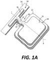
- FIG. 1Ais a perspective of a tether structure, according to illustrative embodiments of the present invention.
- FIG. 1Bis a cross-section and enlargement of illustrative embodiments of the present invention corresponding to cross section line A of FIG. 1A ;
- FIG. 1Cis a plan view of an illustrative embodiment of the present invention corresponding to FIGS. 1A and 1B and indicating cross section line A;
- FIG. 1Dis a micrograph of a constructed and illustrative embodiment of the present invention corresponding to FIGS. 1A, 1B, and 1C ;
- FIG. 2Ais a plan view of a wafer structure, according to illustrative embodiments of the present invention.
- FIG. 2Bis a cross-section of an illustrative embodiment of the present invention corresponding to cross section line A of FIG. 2A ;
- FIGS. 3 and 4are plan views of wafer structures, according to illustrative embodiments of the present invention.
- FIGS. 5A-5Fare sequential cross sections illustrating steps of an illustrative method, according to illustrative embodiments of the present invention.
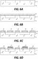
- FIGS. 6A-6Gare sequential cross sections illustrating steps of another illustrative method, according to illustrative embodiments of the present invention.
- FIGS. 7-8are cross sections of wafer structures, according to illustrative embodiments of the present invention.
- FIGS. 9-10are plan views of compound structures, according to illustrative embodiments of the present invention.
- FIG. 11is a plan view of a source wafer having a plurality of wafer structures, according to illustrative embodiments of the present invention.
- FIG. 12is a flow diagram of an illustrative method, according to illustrative embodiments of the present invention.
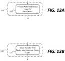
- FIGS. 13A, 13B, and 14are flow diagrams of illustrative methods, according to illustrative embodiments of the present invention.
- FIGS. 15-17are cross sections of wafer structures, according to illustrative embodiments of the present invention.
- FIG. 18is a cross section of a device structure, according to illustrative embodiments of the present invention.
- the present inventionprovides, inter alia, a structure and method for micro-transfer printing micro-devices from a source wafer using a stamp.
- the micro-devicesare attached to anchor portions, or structures provided on or over the anchor portions, of the source wafer with tethers (bridge elements).
- the tethersare structured to fracture at a consistent location in the tether in response to a controlled contact from a stamp without the production of contaminating particles.
- a wafer structure 99comprises a source wafer 10 comprising a patterned sacrificial layer 12 defining one or more anchor portions 16 separating one or more sacrificial portions 14 .
- the separation between the anchor portions 16 and the sacrificial portions 14 of the patterned sacrificial layer 12can be in a direction D parallel to an extensive and substantially planar surface of the source wafer 10 .
- the term ‘substantially’ used hereinrefers to structural attributes made within the tolerances and resolutions of the materials and manufacturing processes.
- FIG. 1Billustrates two of the structures shown in FIGS. 1A, 1C, and 1D .
- a patterned device layer 20can be disposed at least partially on or over the patterned sacrificial layer 12 forming a device anchor 26 on each of the anchor portions 16 .
- the anchor portion 16can comprise the device anchor 26 .
- One or more devices 22are disposed in the patterned device layer 20 , each device 22 disposed entirely over a corresponding one of the one or more sacrificial portions 14 and spatially separated from the one or more device anchors 26 or anchor portions 16 , for example separated in the direction D.
- a tether structure 30connects each device 22 to a device anchor 26 or anchor portion 16 .
- the tether structure 30comprises a tether device portion 32 disposed at least partly on or over the device 22 , a tether anchor portion 36 disposed at least partly on or over the device anchor 26 or anchor portion 16 , and a tether 34 connecting the tether device portion 32 to the tether anchor portion 36 .
- Each tether structure 30is physically continuous.
- Each tether 34is disposed at least partly in the patterned device layer 20 between the device 22 and the device anchor 26 , for example in the direction D. In some embodiments, at least a portion of the tether 34 is disposed exclusively in the patterned device layer 20 between the device and the device anchor 26 in the direction D.
- the tether structure 30is a multi-level or multi-layer structure because it extends into at least two layers or levels in the wafer structure 99 , for example in the patterned device layer 20 and on or over (above) the patterned device layer 20 .
- the source wafer 10can be any structure with a surface suitable for forming patterned sacrificial layers 12 and the patterned device layer 20 .
- source wafers 10can comprise wafers of glass, plastic, metal, ceramic, sapphire, semiconductor, or compound semiconductor materials.
- the semiconductor materialscan be silicon or silicon with a ⁇ 1 1 1 ⁇ or ⁇ 1 0 0 ⁇ crystal structure (e.g., orientation), and the compound semiconductor can be GaAs or GaN, but are not limited to these materials.
- the wafer surfacecan be substantially planar and suitable for photolithographic processing, for example as found in the integrated circuit or printed circuit board art.
- a patterned sacrificial layer 12can comprise a layer of material different from that of the source wafer 10 or can comprise a designated portion of the source wafer 10 and include essentially the same material.
- the source wafer 10is a semiconductor wafer and the patterned sacrificial layer 12 comprises a dielectric such as an oxide (e.g., silicon dioxide) or nitride (e.g., silicon nitride).
- the patterned sacrificial layer 12can comprise different materials, for example an anchor portion 16 can be the same material as the source wafer 10 (e.g., a semiconductor material) and the sacrificial portion 14 can be a dielectric material, for example a dielectric material disposed in a cavity corresponding to the sacrificial portions 14 etched into the patterned sacrificial layer 12 .
- a patterned sacrificial layer 12is a designated layer or portion of a source wafer 10 and the anchor and sacrificial portions 16 , 14 of are likewise designated portions of the patterned sacrificial layer 12 .
- the anchor and sacrificial portions 16 , 14can be distinguished by their defined locations or with reference to a crystalline structure of the source wafer 10 , for example a silicon ⁇ 1 1 1 ⁇ or ⁇ 1 0 0 ⁇ wafer and crystal structure.
- sacrificial portions 14are sacrificed, for example by etching, to form an empty gap G (e.g., not filled with solid or liquid material but possible including a vacuum or filled with a gas such as air, nitrogen, oxygen, or other gases, see FIGS. 6G, 7, and 8 , discussed further below).
- the sacrificial portions 14can comprise a material that is differentially etchable from the source wafer 10 and the anchor portions 16 .
- the source wafer 10 materialhas a crystalline structure (e.g., silicon ⁇ 1 1 1 ⁇ or ⁇ 1 0 0 ⁇ ) that is anisotropically etchable so that the patterned sacrificial layer 12 can be etched to form an empty sacrificial portion 14 (gap G) but not etch the anchor portions 16 .
- a crystalline structuree.g., silicon ⁇ 1 1 1 ⁇ or ⁇ 1 0 0 ⁇
- the patterned sacrificial layer 12can be etched to form an empty sacrificial portion 14 (gap G) but not etch the anchor portions 16 .
- the patterned device layer 20can comprise a layer of material such as a semiconductor or compound semiconductor material (e.g., silicon, GaAs, GaN, or other semiconductor or compound semiconductor materials) or dielectric materials.
- the patterned device layer 20 materialcan be the same material as the source wafer 10 or a different material.
- the devices 22are formed in or have a substrate material that is the patterned device layer 20 material, for example by photolithographic processing, and the device anchor 26 comprises the same substrate material and is separated in the direction D from the devices 22 .
- the patterned device layer 20 materialcan be the same material as the source wafer 10 , for example a semiconductor material or a semiconductor material such as silicon or GaN disposed on an insulator such as glass, sapphire, or quartz, or other epitaxial materials.
- device anchors 26are formed by photolithographic processing but devices 22 are disposed on or over sacrificial portions 14 by placement, for example by micro-transfer printing the devices 22 onto the sacrificial portions 14 .
- a patterned device layer 20 material or the device anchor 26can comprise a different material than the source wafer 10 or the device 22 substrate material, for example a dielectric material.
- the devices 22can be, for example, integrated circuits, control circuits, light emitting diodes (LEDs), photo-sensors, digital circuits, analog circuits, mixed signal circuits, or other devices known in the integrated circuit arts.
- the devices 22can be micro-transfer printed devices 22 disposed on the sacrificial portions 14 and the devices 22 can comprise a fractured or separated tether 34 .
- the physically continuous tether structure 30can comprise any of a variety of materials.
- a tether structure 30is a unitary structure with different portions disposed on different parts of a wafer structure 99 .
- a tether structure 30can comprise or be a dielectric, for example a nitride, an oxide, silicon nitride, silicon oxide, silicon dioxide, silicon oxynitride, aluminum oxide, aluminum nitride, dielectrics deposited by chemical vapor deposition (CVD), or thermally grown oxides or nitrides, such as silicon oxide.
- CVDchemical vapor deposition
- a tether structure 30is a polymer, for example including but not limited to photoresist, polyimide, epoxy, or resin.
- the tether structure 30can be a metal, for example a noble metal.
- Tether structure 30 materialscan be deposited and patterned by photolithographic processes, for example evaporation and sputtering and, in some embodiments, together with curing, etching, and stripping of pattern-wise exposed mask layers.
- a tether structure 30 materialcan be the same or similar material as the device anchor 26 or can be a different material.
- a tether device portion 32 of a tether structure 30can be an encapsulating or protective layer.
- the tether device portion 32can include vias 54 to enable electrical connection to contact pads 50 on the device 22 (not shown in FIGS. 1A-1D but discussed below with respect to FIGS. 9 and 10 ).
- a tether structure 30has a non-planar topography. Portions of the tether 34 of the tether structure 30 are closer to the source wafer 10 than the tether device portion 32 or the tether anchor portion 36 in a vertical direction orthogonal to a horizontal plane substantially parallel to a surface of the source wafer 10 on which the patterned device layer 20 is disposed. Vertical edges of the tether 34 can have a substantially ninety-degree angle 18 with respect to the device anchors 26 and devices 22 in the horizontal plane in the patterned device layer 20 (so that the vertical edges of the tether 34 and the vertical edges of the device portion 26 (or the vertical edges of the device 22 ) form a right angle in the horizontal plane).
- the tether structures 30are non-planar and can have side walls in contact with the devices 22 and the device anchors 26 at a substantially ninety-degree angle 18 , in certain embodiments, when a micro-transfer printing stamp contacts the devices 22 to remove them, the tethers 34 fracture in a very predictable way along fracture lines 38 under a consistent stamp force and generates very few, if any, contaminating particles. Fewer particles, in turn, improve the yield of a micro-transfer print process.
- FIG. 1Ais a perspective and FIG. 1C is a plan view illustrating a tether structure 30 with a tether device portion 32 disposed on a portion of a device 22 , a tether anchor portion 36 disposed on a portion of a device anchor 26 , and a tether 34 connecting the tether device portion 32 and the tether anchor portion 36 and connecting the device anchor 26 to the device 22 .
- the source wafer 10is not shown in FIG. 1A .
- FIG. 1Billustrates a cross section of the wafer structure 99 along cross section line A of FIGS. 1A and 1C , with the source wafer 10 , patterned sacrificial layer 12 , patterned device layer 20 , and tether structure 30 .
- FIG. 1Billustrates a cross section of the wafer structure 99 along cross section line A of FIGS. 1A and 1C , with the source wafer 10 , patterned sacrificial layer 12 , patterned device layer 20 , and t
- 1Dis a micro-graph of a constructed tether structure 30 according to some embodiments of the present invention, showing a tether 34 , tether device portion 32 , tether anchor portion 36 and underlying device anchor 26 , device 22 , and sacrificial portion 14 . Fracture lines 38 are indicated.
- the tether 34has an edge wall at a ninety-degree angle 18 to the edge walls of the underlying device anchor 26 and device 22 in a plane in the patterned device layer 20 and substantially parallel to a surface of the source wafer 10 on which the patterned device layer 20 is disposed and, when fractured, demonstrates superior performance and reduced contamination.
- the tether 34has a second length L 2 within the patterned device layer 20 that is less than the spatial separation between the device anchor 26 and device 22 in the direction D, first length L 1 , because the tether 34 has a physical thickness T.
- the device 22is spatially separated from the device anchor 26 (or the anchor portion 16 ) by a first length L 1
- the tether 34has a tether thickness T
- the tether 34has a second length L 2 exclusively in the device level that is less than the first length L 1 .
- the difference between the first and second lengths L 1 and L 2can be, but is not necessarily the thickness T or twice the thickness T, since the thickness T of the tether structure 30 can vary at different locations within the tether structure 30 .
- the thickness of T and the relative difference between the first and second lengths L 1 and L 2can be controlled to control the fracturing characteristics of the tether 34 , for example depending on the materials or relative sizes of the tether 34 , device anchor 26 , the device 22 , the anchor portion 16 , or the sacrificial portion 14 .
- the second length L 2 plus twice the tether thickness Tis substantially equal to the first length L 1 or is within a range of 0.9 to 1.1, 0.75 to 1.25, or 0.5 to 1.5 times the first length L 1 . Furthermore, because the tether 34 second length L 2 does not have to be separately patterned (but can be formed as a result of patterning the entire tether structure 30 ) the second length L 2 can be smaller than the minimum patternable feature size of the wafer structure 99 .
- the minimum patternable feature sizecan be the first length L 1 that separates the device anchor 26 from the device 22 , or the distance between the sacrificial portions 14 and the anchor portions 16 of the patterned sacrificial layer 12 (that can also be the first length L 1 ).
- Such a small tether 34can enable a denser arrangement of devices 22 and device anchors 26 (corresponding to the density of the anchor portions 16 and sacrificial portions 14 ) on the source wafer 10 , providing improved utilization of the source wafer 10 area and reduced costs.
- the tether device portion 32 of the tether structure 30covers a portion, but not all of, the device 22 .
- the tether anchor portion 36covers only a portion of the device anchor 26 .
- the tether device portion 32 of the tether structure 30covers all of the device 22 , thereby encapsulating the upper portion of the device 22 and protecting it from the environment.
- vias 54are formed in the tether device portion 32 to enable electrical access to device 22 contact pads 50 but the device 22 is otherwise completely encapsulated by the tether device portion 32 (e.g., as shown in FIGS. 9 and 10 , discussed below).
- a device anchor 26can be encapsulated by a tether anchor portion 36 (e.g., as shown in FIG. 2A ).
- one or the other, but not both, of a device anchor 26 and device 22is substantially encapsulated by a tether structure 30 , aside from vias 54 .
- one side of a device anchor 26 and three sides of a device 22are encapsulated by a tether structure 30 .
- the width of the tether 34is enlarged, for example having a width that is more than half of the side of the device 22 parallel to the device anchor 26 .
- a method of making a wafer structure 99comprises providing a source wafer 10 having a patterned sacrificial layer 12 defining one or more anchor portions 16 separating one or more sacrificial portions 14 in step 100 ( FIG. 5A ).
- a device layer 24 of materialis disposed on the patterned sacrificial layer 12 and patterned to form patterned device layer 20 that is at least partially on or over the patterned sacrificial layer 12 .
- the patterned device layer 20provides a device anchor 26 on each of the anchor portions 16 .
- one or more devices 22are disposed in the patterned device layer 20 , each device 22 disposed entirely over a corresponding one of the one or more sacrificial portions 14 and spatially separated from the one or more device anchors 26 .
- tether material 31(for example a dielectric) is disposed on the devices 22 , sacrificial portion 14 , and the device anchor 26 and then patterned to form a tether structure 30 having separate and independent tethers 34 connecting each device 22 to a device anchor 26 , for example as shown in FIGS. 2A and 2B , using photolithographic materials and methods.
- the tether structure 30comprises a tether device portion 32 disposed at least partly on or over the device 22 , a tether anchor portion 36 disposed at least partly on or over the device anchor 26 , and a tether 34 connecting the tether device portion 32 to the tether anchor portion 36 .
- Each tether structure 30is physically continuous.
- Each tether 34is disposed at least partly in the patterned device layer 20 between the device 22 and the device anchor 26 .
- the tether structure 30can be patterned to form openings 40 in the tether structure 30 over the sacrificial portions 14 to allow etchants to attack and dissolve the sacrificial portions 14 in step 140 and form gaps G between the devices 22 and the source wafer 10 ( FIG. 5F ).
- a micro-transfer printing stampcan contact the device 22 , pressing against the device 22 and then lifting away from the source wafer 10 to fracture the tether 34 (step 160 ) and adhere the device 22 to the stamp.
- the stampis removed (step 170 ) to a destination substrate and the device 22 is pressed against the destination substrate in step 180 , to adhere the devices 22 to the destination substrate.
- the stampis then removed (step 190 ) to micro-transfer print the devices 22 from the source wafer 10 to the destination substrate.
- a device 22is formed in a patterned device layer 20 , e.g., as shown in the step 122 of FIG. 13A , by patterning the device layer materials, for example using photolithography.
- a device 22is disposed in a patterned device layer 20 , e.g., as shown in step 123 of FIG. 13B , by micro-transfer printing the device 22 in or on the patterned device layer 20 .
- a wafer structure 99comprises one or more device substrates 28 .
- Each device substrate 28is disposed entirely over a corresponding one of the one or more sacrificial portions 14 .
- One or more components 23are disposed on or over each of the device substrates 28 .
- the device substrate 28provides a surface on which the one or more elements 23 can be integrated and photolithographically connected to form a compound micro-transfer printable device 22 .
- the one or more elements 23can themselves be micro-transfer printed onto the device substrate 28 and can therefore each comprise a fractured tether 34 .
- a source wafer 10is provided having a patterned sacrificial layer 12 defining one or more anchor portions 16 separating one or more sacrificial portions 14 ( FIG. 6A , also FIG. 5A ).
- a device layer 24 of materialis disposed on the patterned sacrificial layer 12 ( FIG. 6B and also FIG. 5B ) and patterned to form the patterned device layer 20 , including the device anchor 26 ( FIG. 6C ).
- the portion of the patterned device layer 20 directly on the sacrificial portions 14is patterned to provide a device substrate 28 (step 124 ).
- the device substrate 28can be the same material as the device anchor 26 , for example a dielectric such as silicon dioxide or silicon nitride, deposited and patterned using photolithographic methods and materials, for example in a common step.
- one or more components 23e.g., integrated circuits, control circuits, light emitting diodes (LEDs), photo-sensors, digital circuits, analog circuits, mixed signal circuits, or other components known in the integrated circuit arts
- the one or more components 23are photolithographically processed to provide contact pads 50 and electrical connections (wires 52 ) that form a circuit incorporating the one or more components 23 .
- tether material 31is disposed on the devices 22 , sacrificial portion 14 , and the device anchor 26 and then patterned to form a tether structure 30 having a separate and independent tether 34 connecting each device 22 to a device anchor 26 , for example as shown in FIGS. 2A and 2B .
- the tether structure 30comprises a tether device portion 32 disposed at least partly on or over the device 22 , a tether anchor portion 36 disposed at least partly on or over the device anchor 26 , and a tether 34 connecting the tether device portion 32 to the tether anchor portion 36 .
- Each tether structure 30is physically continuous.
- Each tether 34is disposed at least partly in the patterned device layer 20 between the device 22 and the device anchor 26
- the tether structure 30can be patterned to form openings 40 in the tether structure 30 over the sacrificial portions 14 to allow etchants to attack and dissolve the sacrificial portions 14 in step 140 and form gaps G between the devices 22 and the source wafer 10 ( FIG. 6G corresponding to FIG. 5F ).
- the steps 150 - 190can then be performed for the structure of FIG. 6G as for that of FIG. 5F and as described above.
- FIGS. 7 and 8are cross sections illustrating some embodiments of a wafer structure 99 , in which components 23 are not micro-transfer printed but are, instead, formed in a patterned device layer 20 using photolithographic materials and processes.
- a portion of the patterned device layer 20is disposed on the device anchor 26 and encapsulated with it by the tether anchor portion 36 of the tether structure 30 .
- the device anchor 26can comprise the same material as the device substrate 28 , for example a dielectric
- the portion of the patterned device layer 20 disposed on the device anchor 26can be or comprise the same material as the components 23 , for example a semiconductor.
- FIG. 7a portion of the patterned device layer 20 is disposed on the device anchor 26 and encapsulated with it by the tether anchor portion 36 of the tether structure 30 .
- the device anchor 26can comprise the same material as the device substrate 28 , for example a dielectric
- the portion of the patterned device layer 20 disposed on the device anchor 26can be or comprise
- the device substrate 28 materialis not present in the device anchor 26 (for example removed photolithographically when the device substrate 28 is formed). Instead, the material used in the components 23 (e.g., a semiconductor) is disposed on the anchor portion 16 to form the device anchor 26 in the patterned device layer 20 .
- a device anchor 26can comprise material found in a device substrate 28 or material found in elements 23 (for example a substrate of a component 23 ), or both.
- FIGS. 9 and 10are plan views of certain embodiments of the present invention.
- FIG. 9illustrates a wafer structure 99 having a device 22 .
- the device 22comprises a device substrate 28 and two micro-transfer printed components, 23 A and 23 B.
- the micro-transfer printed components 23 A and 23 Bhave contact pads 50 that are exposed through vias 54 in the tether device portion 32 of the tether structure 30 and provide electrical contact to circuits in the components 23 A and 23 B.
- the contact pads 50are electrically connected with wires 52 photolithographically formed on the device substrate 28 and components 23 A and 23 B.
- FIG. 10illustrates a wafer structure 99 , according to certain embodiments, incorporating a control circuit (component 23 A) controlling three LEDs (components 23 R 23 G, 23 B that emit red, green, and blue light, respectively).
- FIG. 11is a large-scale plan view of a source wafer 10 incorporating a plurality of wafer structures 99 arranged in an array on the source wafer 10 .
- the device anchors 26 in each column of wafer structures 99are joined as are the tether anchor portions 36 of the tether structures 30 into contiguous structures.
- sacrificial portions 14are differentially etchable from devices 22 and a source wafer 10 , either because the material of the sacrificial portions 14 is different from the material of the source wafer 10 or because the material of the source wafer 10 is anisotropically etchable so that a designated portion of the source wafer 10 (the sacrificial portions 14 ) can be etched.
- a variety of material typescan be used for the source wafer 10 and the sacrificial portions 14 . However, some combinations of materials can encounter processing difficulties, for example due to material oxidation. For example, the surface of sacrificial portions 14 can oxidize and form particles that interfere with the processing and construction or deposition of devices 22 over or on the sacrificial portions 14 .
- a portion of a patterned device layer 20 disposed over sacrificial portions 14incorporates multiple material layers, for example a lower layer 60 adjacent to the one or more sacrificial portions 14 and an upper layer 62 on a side of the lower layer 60 opposite the one or more sacrificial portions 14 .
- a device 22is formed in an upper layer 62 , for example a semiconductor layer; in some embodiments, a device 22 is disposed on a lower layer 60 to form an upper layer 62 , for example by micro-transfer printing.
- the device 22is disposed entirely over a corresponding one of the one or more sacrificial portions 14 and is spatially separated from the one or more device anchors 26 or anchor portions 16 .
- a lower layer 60extends over more of a sacrificial portion 14 than an upper layer 62 or a device 22 .
- a lower layer 60can serve as an etch protectant (e.g., etch-stop layer) to a device 22 when a sacrificial portion 14 is etched. Furthermore, a lower layer 60 can serve as a protective encapsulation layer for the material of a sacrificial portion 14 , for example to prevent oxidation during photolithographic processing steps performed on, or to construct, a device 22 or tether structure 30 . Although edges of sacrificial portions 14 can be exposed to processing materials, for example, that could oxidize the edges of the sacrificial portion 14 material, the exposure is sufficiently limited that it does not interfere with the construction or disposition of the device 22 (or components 23 ) in the patterned device layer 20 .
- a lower layer 60 and device 22 or upper layer 2can comprise the same material or be the same material as the source wafer 10 .
- lower and upper layers 60 , 62can be the same material or a unitary structure.
- a lower layer 60can have a greater extent over a source wafer 10 than upper layer 62 or a device 22 , for example, so that a device 22 forms a mesa or pedestal on the lower layer 60 .
- upper and lower layers 62 , 60are a single substrate material deposited and patterned on the sacrificial portion 14 together and then subsequently processed to form a device 22 (that can include other patterned materials such as dielectrics and metals) in the upper layer 62 without further processing the lower layer 60 .
- the upper and lower layers 62 , 60comprise the same material, for example a semiconductor substrate material such as GaAs and the device anchor 26 comprises the same material.
- the device anchor 26can have a thickness (depth) corresponding to the thickness (depth) of the lower level 60 (as shown in FIG. 17 ) or a depth corresponding to the entire device layer 30 .
- a device structure 98for example a micro-transfer printed device 22 removed from the wafer structure 99 , comprises a lower layer 60 comprising a semiconductor material having a lateral extent, a patterned upper layer 62 comprising a semiconductor device 22 disposed entirely on the lower layer 60 , the semiconductor device 22 comprising the semiconductor material and having a lateral extent less than or equal to the lateral extent of the lower layer 60 , and a physically continuous tether structure 30 comprising a tether device portion 32 disposed at least partly on at least one of the device 22 , the upper layer 62 , and the lower layer 60 and a tether 34 adjacent to, optionally in contact with the lower level 60 , and in a common layer with the lower level 60 .
- the semiconductor materialcan be GaAs and the tether structure 30 can comprise a dielectric.
- a source wafer 10comprises a patterned device layer 20 comprising a GaAs lower layer 60 , an upper layer 62 forming a device 22 that also incorporates or comprises GaAs, and a sacrificial portion 14 over which the device 22 is disposed comprising a layer of AlGaAs.
- the source wafer 10can be a GaAs wafer. Both the device 22 (upper layer 62 ) and the sacrificial portion 14 are protected by the lower layer 60 .
- the lower layer 60if made of GaAs can be patterned using common GaAs etchants, such as phosphoric acid plus peroxide or ammonium hydroxide plus peroxide.
- AlGaAscan be etched using HCl or HF to release the device 22 from the source wafer 10 with a clean surface on the lower layer 60 for micro-transfer printing to a destination substrate. This method and structure has been demonstrated to enable the construction of micro-transfer printable GaAs devices 22 with good performance and yields.
- a device 22 or component 23can be an active circuit component, for example including one or more active electronic components such as electronic transistors or diodes or light-emitting diodes and photodiodes that produce an electrical current in response to ambient light.
- a device 22 or component 23can be a passive component, for example including one or more passive elements such as resistors, capacitors, or conductors.
- a device 22 or component 23includes both active and passive elements.
- a device 22 or component 23can be a semiconductor device having one or more semiconductor layers, such as an integrated circuit.
- a device 22 or component 23can be an unpackaged die.
- a device 22is a compound device 22 having a plurality of active or passive elements, such as multiple semiconductor components 23 with separate substrates, each with one or more active elements or passive elements, or both.
- the plurality of components 23is disposed and interconnected on a device substrate 28 separate from the substrates of any semiconductor devices.
- the compound device 22can be micro transfer printed itself after the components 23 have been arranged thereon.
- Devices 22 or components 23can be electronic processors, controllers, drivers, light-emitting diodes, photodiodes, light-control devices, or light-management devices.
- Devices 22 or components 23can include active elements such as electronic circuits formed using lithographic processes and can include passive elements such as electrical connections, e.g., wires 52 , to contact pads 50 .
- the contact pads 50are planar electrical connections formed on the process side of the devices 22 or components 23 and source wafer 10 .
- Such contact pads 50are typically formed from metals such as aluminum or polysilicon using masking and deposition processes used in the art.
- the contact pads 50are electrically connected to component or device circuits 29 with wires 52 .
- the contact pads 50are directly electrically connected to the circuit without intervening wires 52 .
- devices 22 or components 23are small integrated circuits, for example chiplets, having a thin substrate with at least one of a thickness of only a few microns, for example less than or equal to 25 microns, less than or equal to 15 microns, or less than or equal to 10 microns, and a width of 5-1000 microns (e.g., 5-10 microns, 10-50 microns, 50-100 microns, or 100-1000 microns) and a length of 5-1000 microns (e.g., 5-10 microns, 10-50 microns, 50-100 microns, or 100-1000 microns).
- a thin substratewith at least one of a thickness of only a few microns, for example less than or equal to 25 microns, less than or equal to 15 microns, or less than or equal to 10 microns, and a width of 5-1000 microns (e.g., 5-10 microns, 10-50 microns, 50-100 microns, or 100-1000 micron
- Such chipletscan be made in a native source semiconductor wafer (e.g., a silicon or GaN wafer) having a process side and a back side used to handle and transport the wafer using lithographic processes.
- the devices 22 or components 23are formed using lithographic processes in an active layer on or in the process side of the source wafer 10 . Methods of forming such structures are described, for example, in U.S. Pat. No. 8,889,485.
- component 23 source wafers 10can be provided with components 23 , release layer, and tethers 34 already formed, or they can be constructed as part of the process in accordance with certain embodiments of the present invention.
- devices 22 or components 23are small integrated circuits formed in a semiconductor wafer, for example gallium arsenide or silicon, which can have a crystalline structure. Processing technologies for these materials typically employ high heat and reactive chemicals. However, by employing transfer technologies that do not stress devices 22 or components 23 or substrate materials, more benign environmental conditions can be used compared to thin-film manufacturing processes. Thus, certain embodiments of the present invention have an advantage in that flexible substrates, such as polymeric substrates, that are intolerant of extreme processing conditions (e.g. heat, chemical, or mechanical processes) can be employed for the destination substrates. Furthermore, it has been demonstrated that crystalline silicon substrates have strong mechanical properties and, in small sizes, can be relatively flexible and tolerant of mechanical stress.
- extreme processing conditionse.g. heat, chemical, or mechanical processes
- Components 23can be formed in a microcrystalline, polycrystalline, or amorphous semiconductor layer.
- a source wafer 10is a native source wafer 10 to components 23 or devices 22 , for example comprising a semiconductor.
- a source wafer 10is not a native source wafer 10 to components 23 or devices 22 , for example comprising a dielectric.
- devices 22 or components 23can be constructed using foundry fabrication processes used in the art. Layers of materials can be used, including materials such as metals, oxides, nitrides and other materials used in the integrated-circuit art. Each device 22 or component 23 can be a complete semiconductor integrated circuit and can include, for example, transistors. Components 23 can have different sizes, for example, less than 1000 square microns or less than 10,000 square microns, less than 100,000 square microns, or less than 1 square mm, or larger, and can have variable aspect ratios, for example 1:1, 2:1, 5:1, or 10:1. Components 23 can be rectangular or can have other shapes.
- a first layer on a second layerin some implementations means a first layer directly on and in contact with a second layer.
- a first layer on a second layerincludes a first layer and a second layer with another layer therebetween.
Landscapes
- Engineering & Computer Science (AREA)
- Physics & Mathematics (AREA)
- Condensed Matter Physics & Semiconductors (AREA)
- General Physics & Mathematics (AREA)
- Manufacturing & Machinery (AREA)
- Computer Hardware Design (AREA)
- Microelectronics & Electronic Packaging (AREA)
- Power Engineering (AREA)
- Mechanical Engineering (AREA)
- Micromachines (AREA)
- Internal Circuitry In Semiconductor Integrated Circuit Devices (AREA)
- Junction Field-Effect Transistors (AREA)
Abstract
Description
- A cross section line
- D direction
- G gap
- L1, L2 length
- T thickness
- 10 source wafer
- 12 sacrificial layer
- 14 sacrificial portion
- 16 anchor portion
- 18 ninety-degree angle
- 20 patterned device layer
- 22 device
- 23,23A,23B,23G,23R component
- 24 device layer
- 26 device anchor
- 28 device substrate
- 29 device circuit
- 30 tether structure
- 31 tether material
- 32 tether device portion
- 34 tether
- 36 tether anchor portion
- 38 fracture line
- 40 opening
- 50 contact pad
- 52 wire
- 54 via
- 60 lower layer
- 62 upper layer
- 98 device structure
- 99 wafer structure
- 100 provide source wafer step
- 110 dispose patterned device layer step
- 120 dispose device on patterned device layer step
- 122 process patterned device layer to form device step
- 123 micro-transfer print device in patterned device layer step
- 124 form device substrate over sacrificial portion step
- 126 micro-transfer print devices(s) onto device substrate step
- 128 process devices(s) and device substrate to form device circuit step
- 130 form tether structure step
- 140 etch sacrificial portions step
- 150 contact device with stamp step
- 160 fracture tether step
- 170 remove stamp with adhered device step
- 180 press device against destination substrate step
- 190 remove stamp step
Claims (28)
Priority Applications (3)
| Application Number | Priority Date | Filing Date | Title |
|---|---|---|---|
| US16/058,097US10832935B2 (en) | 2017-08-14 | 2018-08-08 | Multi-level micro-device tethers |
| US16/921,556US11670533B2 (en) | 2017-08-14 | 2020-07-06 | Multi-level micro-device tethers |
| US18/140,427US12249532B2 (en) | 2017-08-14 | 2023-04-27 | Multi-level micro-device tethers |
Applications Claiming Priority (2)
| Application Number | Priority Date | Filing Date | Title |
|---|---|---|---|
| US201762545413P | 2017-08-14 | 2017-08-14 | |
| US16/058,097US10832935B2 (en) | 2017-08-14 | 2018-08-08 | Multi-level micro-device tethers |
Related Child Applications (1)
| Application Number | Title | Priority Date | Filing Date |
|---|---|---|---|
| US16/921,556DivisionUS11670533B2 (en) | 2017-08-14 | 2020-07-06 | Multi-level micro-device tethers |
Publications (2)
| Publication Number | Publication Date |
|---|---|
| US20190051552A1 US20190051552A1 (en) | 2019-02-14 |
| US10832935B2true US10832935B2 (en) | 2020-11-10 |
Family
ID=65275575
Family Applications (3)
| Application Number | Title | Priority Date | Filing Date |
|---|---|---|---|
| US16/058,097ActiveUS10832935B2 (en) | 2017-08-14 | 2018-08-08 | Multi-level micro-device tethers |
| US16/921,556ActiveUS11670533B2 (en) | 2017-08-14 | 2020-07-06 | Multi-level micro-device tethers |
| US18/140,427ActiveUS12249532B2 (en) | 2017-08-14 | 2023-04-27 | Multi-level micro-device tethers |
Family Applications After (2)
| Application Number | Title | Priority Date | Filing Date |
|---|---|---|---|
| US16/921,556ActiveUS11670533B2 (en) | 2017-08-14 | 2020-07-06 | Multi-level micro-device tethers |
| US18/140,427ActiveUS12249532B2 (en) | 2017-08-14 | 2023-04-27 | Multi-level micro-device tethers |
Country Status (1)
| Country | Link |
|---|---|
| US (3) | US10832935B2 (en) |
Cited By (7)
| Publication number | Priority date | Publication date | Assignee | Title |
|---|---|---|---|---|
| US11088007B1 (en) | 2020-05-07 | 2021-08-10 | X-Celeprint Limited | Component tethers with spacers |
| WO2022099418A1 (en)* | 2020-11-12 | 2022-05-19 | Vuereal Inc. | Optoelectronic microdevice |
| US20230036209A1 (en)* | 2020-01-10 | 2023-02-02 | Rockley Photonics Limited | Source wafer and method of preparation thereof |
| US12057340B2 (en) | 2020-12-04 | 2024-08-06 | X-Celeprint Limited | Hybrid tethers for micro-transfer printing |
| US20240304748A1 (en)* | 2023-03-12 | 2024-09-12 | X-Celeprint Limited | Vertical tethers for micro-transfer printing |
| US12249532B2 (en) | 2017-08-14 | 2025-03-11 | X Display Company Technology Limited | Multi-level micro-device tethers |
| US12342663B2 (en) | 2021-03-18 | 2025-06-24 | Lextar Electronics Corporation | Semiconductor chip with protruding portion and light-emitting device having the same |
Families Citing this family (15)
| Publication number | Priority date | Publication date | Assignee | Title |
|---|---|---|---|---|
| DE102017126338A1 (en)* | 2017-11-10 | 2019-05-16 | Osram Opto Semiconductors Gmbh | Composite component, component and method for the production of components |
| CN108231968B (en)* | 2017-12-11 | 2020-02-11 | 厦门市三安光电科技有限公司 | Micro light emitting diode and transfer method thereof |
| US10832934B2 (en) | 2018-06-14 | 2020-11-10 | X Display Company Technology Limited | Multi-layer tethers for micro-transfer printing |
| US11274035B2 (en) | 2019-04-24 | 2022-03-15 | X-Celeprint Limited | Overhanging device structures and related methods of manufacture |
| US12162747B2 (en) | 2018-12-03 | 2024-12-10 | X-Celeprint Limited | Enclosed cavity structures |
| DE102019126862A1 (en)* | 2019-10-07 | 2021-04-08 | OSRAM Opto Semiconductors Gesellschaft mit beschränkter Haftung | Component composite, method for detaching components from a component composite and method for producing a component composite |
| US11574895B2 (en)* | 2019-12-19 | 2023-02-07 | Innolux Corporation | Method of manufacturing electronic device |
| US11194063B2 (en)* | 2019-12-30 | 2021-12-07 | Rayence Co., Ltd. | X-ray detector having driver micro integrated chips printed on photodiode layer |
| GB2593260B (en)* | 2020-03-17 | 2024-06-26 | Rockley Photonics Ltd | Coupon wafer and method of preparation thereof |
| WO2021224284A1 (en)* | 2020-05-05 | 2021-11-11 | X-Celeprint Limited | Enclosed cavity structures |
| WO2022019200A1 (en)* | 2020-07-20 | 2022-01-27 | Agc株式会社 | Transparent display device and manufacturing method therefor |
| TWI795790B (en) | 2021-05-26 | 2023-03-11 | 隆達電子股份有限公司 | Light emitting element and display device using the same |
| US12400883B2 (en)* | 2022-03-23 | 2025-08-26 | Vanguard International Semiconductor Corporation | Structure of transferring dies for use in mass transferring process |
| EP4599279A1 (en)* | 2022-10-07 | 2025-08-13 | X-Celeprint Limited | Transfer-printed micro-optical components |
| US20240118489A1 (en)* | 2022-10-07 | 2024-04-11 | X-Celeprint Limited | Transfer-printed micro-optical components |
Citations (88)
| Publication number | Priority date | Publication date | Assignee | Title |
|---|---|---|---|---|
| US3673471A (en) | 1970-10-08 | 1972-06-27 | Fairchild Camera Instr Co | Doped semiconductor electrodes for mos type devices |
| US5475224A (en) | 1994-08-26 | 1995-12-12 | Grumman Aerospace Corporation | Infrared detector substrate with breakaway test tabs |
| US5621555A (en) | 1993-12-31 | 1997-04-15 | Goldstar Co., Ltd. | Liquid crystal display having redundant pixel electrodes and thin film transistors and a manufacturing method thereof |
| US5815303A (en) | 1997-06-26 | 1998-09-29 | Xerox Corporation | Fault tolerant projective display having redundant light modulators |
| US5882532A (en) | 1996-05-31 | 1999-03-16 | Hewlett-Packard Company | Fabrication of single-crystal silicon structures using sacrificial-layer wafer bonding |
| US6051472A (en) | 1996-09-26 | 2000-04-18 | Nec Corporation | Semiconductor device and method of producing the same |
| US6142358A (en) | 1997-05-31 | 2000-11-07 | The Regents Of The University Of California | Wafer-to-wafer transfer of microstructures using break-away tethers |
| US6278242B1 (en) | 2000-03-20 | 2001-08-21 | Eastman Kodak Company | Solid state emissive display with on-demand refresh |
| US20030062580A1 (en) | 2000-06-30 | 2003-04-03 | Rie Sato | Spin-valve transistor |
| US6577367B2 (en) | 2000-01-12 | 2003-06-10 | Lg. Philips Lcd Co., Ltd | Array substrate for a liquid crystal display device and method for fabricating the same |
| US20030141570A1 (en) | 2002-01-28 | 2003-07-31 | Chen Shiuh-Hui Steven | Semiconductor wafer having a thin die and tethers and methods of making the same |
| US6717560B2 (en) | 2000-05-15 | 2004-04-06 | Eastman Kodak Company | Self-illuminating imaging device |
| US6756576B1 (en) | 2000-08-30 | 2004-06-29 | Micron Technology, Inc. | Imaging system having redundant pixel groupings |
| JP2005108943A (en) | 2003-09-29 | 2005-04-21 | Oki Data Corp | Semiconductor wafer and method of manufacturing semiconductor device using the same |
| US6933532B2 (en) | 2003-03-28 | 2005-08-23 | Eastman Kodak Company | OLED display with photosensor |
| JP2005259912A (en) | 2004-03-10 | 2005-09-22 | Shin Etsu Handotai Co Ltd | Manufacturing method of light emitting element |
| US20060063309A1 (en)* | 2004-09-21 | 2006-03-23 | Eiji Sugiyama | Method for manufacturing semiconductor device |
| US20060079010A1 (en) | 2004-09-30 | 2006-04-13 | Seiko Epson Corporation | Transfer base substrate and method of semiconductor device |
| JP2006108441A (en) | 2004-10-06 | 2006-04-20 | Mitsubishi Chemicals Corp | Etching method of compound semiconductor |
| US20060145177A1 (en) | 2003-02-28 | 2006-07-06 | Kazunori Hagimoto | Light emitting device and process for fabricating the same |
| US20070032089A1 (en) | 2004-06-04 | 2007-02-08 | The Board Of Trustees Of The University Of Illinois | Printable Semiconductor Structures and Related Methods of Making and Assembling |
| US7195733B2 (en) | 2004-04-27 | 2007-03-27 | The Board Of Trustees Of The University Of Illinois | Composite patterning devices for soft lithography |
| US20070173034A1 (en) | 2004-03-22 | 2007-07-26 | Semiconductor Energy Laboratory Co., Ltd. | Method for manufacturing integrated circuit |
| US7288753B2 (en) | 2004-05-05 | 2007-10-30 | Eastman Kodak Company | OLED display with composite photosensor |
| US20070281556A1 (en) | 2006-06-05 | 2007-12-06 | Homac Mfg. Company | Electrical connector with plug tether assembly and related methods |
| WO2008036837A2 (en) | 2006-09-20 | 2008-03-27 | The Board Of Trustees Of The University Of Illinois | Release strategies for making transferable semiconductor structures, devices and device components |
| US20080079246A1 (en) | 2006-09-29 | 2008-04-03 | Nissan Technical Center North America, Inc. | Tether guided inflatable sail panel |
| US7399693B2 (en) | 2004-06-23 | 2008-07-15 | Canon Kabushiki Kaisha | Semiconductor film manufacturing method and substrate manufacturing method |
| WO2008103931A2 (en) | 2007-02-23 | 2008-08-28 | Strategic Patent Acquisitions Llc | Techniques for three dimensional displays |
| US7521292B2 (en) | 2004-06-04 | 2009-04-21 | The Board Of Trustees Of The University Of Illinois | Stretchable form of single crystal silicon for high performance electronics on rubber substrates |
| JP2009105450A (en) | 2009-02-09 | 2009-05-14 | Oki Data Corp | Laminate |
| US7557367B2 (en) | 2004-06-04 | 2009-07-07 | The Board Of Trustees Of The University Of Illinois | Stretchable semiconductor elements and stretchable electrical circuits |
| US20090202089A1 (en) | 2007-06-06 | 2009-08-13 | Analog Devices, Inc. | Microphone with Reduced Parasitic Capacitance |
| US7586497B2 (en) | 2005-12-20 | 2009-09-08 | Eastman Kodak Company | OLED display with improved power performance |
| US7662545B2 (en) | 2004-10-14 | 2010-02-16 | The Board Of Trustees Of The University Of Illinois | Decal transfer lithography |
| US7704684B2 (en) | 2003-12-01 | 2010-04-27 | The Board Of Trustees Of The University Of Illinois | Methods and devices for fabricating three-dimensional nanoscale structures |
| US20100248484A1 (en) | 2009-03-26 | 2010-09-30 | Christopher Bower | Methods of Forming Printable Integrated Circuit Devices and Devices Formed Thereby |
| US7816856B2 (en) | 2009-02-25 | 2010-10-19 | Global Oled Technology Llc | Flexible oled display with chiplets |
| US20100306993A1 (en) | 2007-11-20 | 2010-12-09 | Board Of Regents, The University Of Texas System | Method and Apparatus for Detethering Mesoscale, Microscale, and Nanoscale Components and Devices |
| US20100317132A1 (en) | 2009-05-12 | 2010-12-16 | Rogers John A | Printed Assemblies of Ultrathin, Microscale Inorganic Light Emitting Diodes for Deformable and Semitransparent Displays |
| US20100326518A1 (en) | 2008-02-21 | 2010-12-30 | Hiroyuki Juso | Solar cell and method of manufacturing solar cell |
| US7893612B2 (en) | 2008-02-27 | 2011-02-22 | Global Oled Technology Llc | LED device having improved light output |
| JP2011066130A (en) | 2009-09-16 | 2011-03-31 | Seiko Epson Corp | Method of manufacturing semiconductor circuit device, semiconductor circuit device, and electronic apparatus |
| US7927976B2 (en) | 2008-07-23 | 2011-04-19 | Semprius, Inc. | Reinforced composite stamp for dry transfer printing of semiconductor elements |
| US7943491B2 (en) | 2004-06-04 | 2011-05-17 | The Board Of Trustees Of The University Of Illinois | Pattern transfer printing by kinetic control of adhesion to an elastomeric stamp |
| US7972875B2 (en) | 2007-01-17 | 2011-07-05 | The Board Of Trustees Of The University Of Illinois | Optical systems fabricated by printing-based assembly |
| US7999454B2 (en) | 2008-08-14 | 2011-08-16 | Global Oled Technology Llc | OLED device with embedded chip driving |
| US8029139B2 (en) | 2008-01-29 | 2011-10-04 | Eastman Kodak Company | 2D/3D switchable color display apparatus with narrow band emitters |
| WO2011123285A1 (en) | 2010-03-29 | 2011-10-06 | Semprius, Inc. | Selective transfer of active components |
| US8207547B2 (en) | 2009-06-10 | 2012-06-26 | Brudgelux, Inc. | Thin-film LED with P and N contacts electrically isolated from the substrate |
| US8261660B2 (en) | 2009-07-22 | 2012-09-11 | Semprius, Inc. | Vacuum coupled tool apparatus for dry transfer printing semiconductor elements |
| US20120228669A1 (en) | 2009-09-16 | 2012-09-13 | Christopher Bower | High-yield fabrication of large-format substrates with distributed, independent control elements |
| US20120314388A1 (en) | 2011-06-08 | 2012-12-13 | Semprius, Inc. | Substrates with transferable chiplets |
| US8334545B2 (en) | 2010-03-24 | 2012-12-18 | Universal Display Corporation | OLED display architecture |
| US20130069275A1 (en) | 2011-09-20 | 2013-03-21 | Etienne Menard | Printing transferable components using microstructured elastomeric surfaces with pressure modulated reversible adhesion |
| US20130088416A1 (en) | 2011-10-11 | 2013-04-11 | Cambridge Display Technology Limited | OLED Display Driver Circuits and Techniques |
| US8470701B2 (en) | 2008-04-03 | 2013-06-25 | Advanced Diamond Technologies, Inc. | Printable, flexible and stretchable diamond for thermal management |
| US20130196474A1 (en) | 2010-08-06 | 2013-08-01 | Matthew Meitl | Materials and processes for releasing printable compound semiconductor devices |
| US8502192B2 (en) | 2010-01-12 | 2013-08-06 | Varian Semiconductor Equipment Associates, Inc. | LED with uniform current spreading and method of fabrication |
| US8506867B2 (en) | 2008-11-19 | 2013-08-13 | Semprius, Inc. | Printing semiconductor elements by shear-assisted elastomeric stamp transfer |
| US20130207964A1 (en) | 2012-02-15 | 2013-08-15 | Rod G. Fleck | Imaging structure with embedded light sources |
| US20130221355A1 (en) | 2010-08-26 | 2013-08-29 | Christopher Bower | Structures and methods for testing printable integrated circuits |
| US8686447B2 (en) | 2011-03-01 | 2014-04-01 | Sony Corporation | Light emitting unit and display device |
| US20140104243A1 (en) | 2012-10-15 | 2014-04-17 | Kapil V. Sakariya | Content-Based Adaptive Refresh Schemes For Low-Power Displays |
| US8766970B2 (en) | 2008-05-05 | 2014-07-01 | Au Optronics Corporation | Pixel circuit, display panel, and driving method thereof |
| US8779484B2 (en) | 2012-11-29 | 2014-07-15 | United Microelectronics Corp. | Image sensor and process thereof |
| US8791474B1 (en) | 2013-03-15 | 2014-07-29 | LuxVue Technology Corporation | Light emitting diode display with redundancy scheme |
| US8794501B2 (en) | 2011-11-18 | 2014-08-05 | LuxVue Technology Corporation | Method of transferring a light emitting diode |
| US8803857B2 (en) | 2011-02-10 | 2014-08-12 | Ronald S. Cok | Chiplet display device with serial control |
| US8817369B2 (en) | 2009-08-31 | 2014-08-26 | Samsung Display Co., Ltd. | Three dimensional display device and method of controlling parallax barrier |
| US8835940B2 (en) | 2012-09-24 | 2014-09-16 | LuxVue Technology Corporation | Micro device stabilization post |
| US20140267683A1 (en) | 2013-03-15 | 2014-09-18 | LuxVue Technology Corporation | Method of fabricating a light emitting diode display with integrated defect detection test |
| US20140264763A1 (en) | 2013-03-15 | 2014-09-18 | Semprius, Inc. | Engineered substrates for semiconductor epitaxy and methods of fabricating the same |
| US8854294B2 (en) | 2009-03-06 | 2014-10-07 | Apple Inc. | Circuitry for independent gamma adjustment points |
| US20140340900A1 (en) | 2013-05-14 | 2014-11-20 | LuxVue Technology Corporation | Stabilization structure including shear release posts |
| US20140367633A1 (en) | 2013-06-18 | 2014-12-18 | LuxVue Technology Corporation | Led display with wavelength conversion layer |
| US20150028362A1 (en) | 2013-07-26 | 2015-01-29 | LuxVue Technology Corporation | Adhesive wafer bonding with controlled thickness variation |
| US8987765B2 (en) | 2013-06-17 | 2015-03-24 | LuxVue Technology Corporation | Reflective bank structure and method for integrating a light emitting device |
| US20150137187A1 (en) | 2012-07-24 | 2015-05-21 | Sumitomo Chemical Company, Limited | Semiconductor wafer, manufacturing method of semiconductor wafer and method for maunfacturing composite wafer |
| US9161448B2 (en) | 2010-03-29 | 2015-10-13 | Semprius, Inc. | Laser assisted transfer welding process |
| WO2015193435A1 (en) | 2014-06-18 | 2015-12-23 | X-Celeprint Limited | Systems and methods for controlling release of transferable semiconductor structures |
| US20150372053A1 (en) | 2014-06-18 | 2015-12-24 | X-Celeprint Limited | Micro assembled led displays and lighting elements |
| US20160020131A1 (en) | 2014-07-20 | 2016-01-21 | X-Celeprint Limited | Apparatus and methods for micro-transfer-printing |
| US20160086855A1 (en) | 2014-06-18 | 2016-03-24 | X-Celeprint Limited | Systems and methods for controlling release of transferable semiconductor structures |
| US20160093600A1 (en) | 2014-09-25 | 2016-03-31 | X-Celeprint Limited | Compound micro-assembly strategies and devices |
| US20170047306A1 (en) | 2015-08-11 | 2017-02-16 | X-Celeprint Limited | Stamp with structured posts |
| US20170256521A1 (en) | 2016-03-03 | 2017-09-07 | X-Celeprint Limited | Micro-transfer printable electronic component |
| US20180096964A1 (en) | 2016-10-03 | 2018-04-05 | X-Celeprint Limited | Micro-transfer printing with volatile adhesive layer |
Family Cites Families (3)
| Publication number | Priority date | Publication date | Assignee | Title |
|---|---|---|---|---|
| WO2015193436A1 (en) | 2014-06-18 | 2015-12-23 | X-Celeprint Limited | Systems and methods for preparing gan and related materials for micro assembly |
| US10008483B2 (en)* | 2016-04-05 | 2018-06-26 | X-Celeprint Limited | Micro-transfer printed LED and color filter structure |
| US10832935B2 (en) | 2017-08-14 | 2020-11-10 | X Display Company Technology Limited | Multi-level micro-device tethers |
- 2018
- 2018-08-08USUS16/058,097patent/US10832935B2/enactiveActive
- 2020
- 2020-07-06USUS16/921,556patent/US11670533B2/enactiveActive
- 2023
- 2023-04-27USUS18/140,427patent/US12249532B2/enactiveActive
Patent Citations (120)
| Publication number | Priority date | Publication date | Assignee | Title |
|---|---|---|---|---|
| US3673471A (en) | 1970-10-08 | 1972-06-27 | Fairchild Camera Instr Co | Doped semiconductor electrodes for mos type devices |
| US5621555A (en) | 1993-12-31 | 1997-04-15 | Goldstar Co., Ltd. | Liquid crystal display having redundant pixel electrodes and thin film transistors and a manufacturing method thereof |
| US5475224A (en) | 1994-08-26 | 1995-12-12 | Grumman Aerospace Corporation | Infrared detector substrate with breakaway test tabs |
| US5882532A (en) | 1996-05-31 | 1999-03-16 | Hewlett-Packard Company | Fabrication of single-crystal silicon structures using sacrificial-layer wafer bonding |
| US6051472A (en) | 1996-09-26 | 2000-04-18 | Nec Corporation | Semiconductor device and method of producing the same |
| US6142358A (en) | 1997-05-31 | 2000-11-07 | The Regents Of The University Of California | Wafer-to-wafer transfer of microstructures using break-away tethers |
| US5815303A (en) | 1997-06-26 | 1998-09-29 | Xerox Corporation | Fault tolerant projective display having redundant light modulators |
| US6577367B2 (en) | 2000-01-12 | 2003-06-10 | Lg. Philips Lcd Co., Ltd | Array substrate for a liquid crystal display device and method for fabricating the same |
| US6278242B1 (en) | 2000-03-20 | 2001-08-21 | Eastman Kodak Company | Solid state emissive display with on-demand refresh |
| US6717560B2 (en) | 2000-05-15 | 2004-04-06 | Eastman Kodak Company | Self-illuminating imaging device |
| US20030062580A1 (en) | 2000-06-30 | 2003-04-03 | Rie Sato | Spin-valve transistor |
| US7129457B2 (en) | 2000-08-30 | 2006-10-31 | Micron Technology, Inc. | Redundant imaging systems |
| US6756576B1 (en) | 2000-08-30 | 2004-06-29 | Micron Technology, Inc. | Imaging system having redundant pixel groupings |
| US20030141570A1 (en) | 2002-01-28 | 2003-07-31 | Chen Shiuh-Hui Steven | Semiconductor wafer having a thin die and tethers and methods of making the same |
| US20060145177A1 (en) | 2003-02-28 | 2006-07-06 | Kazunori Hagimoto | Light emitting device and process for fabricating the same |
| US6933532B2 (en) | 2003-03-28 | 2005-08-23 | Eastman Kodak Company | OLED display with photosensor |
| JP2005108943A (en) | 2003-09-29 | 2005-04-21 | Oki Data Corp | Semiconductor wafer and method of manufacturing semiconductor device using the same |
| US7704684B2 (en) | 2003-12-01 | 2010-04-27 | The Board Of Trustees Of The University Of Illinois | Methods and devices for fabricating three-dimensional nanoscale structures |
| JP2005259912A (en) | 2004-03-10 | 2005-09-22 | Shin Etsu Handotai Co Ltd | Manufacturing method of light emitting element |
| US20070173034A1 (en) | 2004-03-22 | 2007-07-26 | Semiconductor Energy Laboratory Co., Ltd. | Method for manufacturing integrated circuit |
| US7195733B2 (en) | 2004-04-27 | 2007-03-27 | The Board Of Trustees Of The University Of Illinois | Composite patterning devices for soft lithography |
| US7288753B2 (en) | 2004-05-05 | 2007-10-30 | Eastman Kodak Company | OLED display with composite photosensor |
| US8198621B2 (en) | 2004-06-04 | 2012-06-12 | The Board Of Trustees Of The University Of Illinois | Stretchable form of single crystal silicon for high performance electronics on rubber substrates |
| US8039847B2 (en) | 2004-06-04 | 2011-10-18 | The Board Of Trustees Of The University Of Illinois | Printable semiconductor structures and related methods of making and assembling |
| US8440546B2 (en) | 2004-06-04 | 2013-05-14 | The Board Of Trustees Of The University Of Illinois | Methods and devices for fabricating and assembling printable semiconductor elements |
| US8754396B2 (en) | 2004-06-04 | 2014-06-17 | The Board Of Trustees Of The University Of Illinois | Stretchable form of single crystal silicon for high performance electronics on rubber substrates |
| US8394706B2 (en) | 2004-06-04 | 2013-03-12 | The Board Of Trustees Of The University Of Illinois | Printable semiconductor structures and related methods of making and assembling |
| US7622367B1 (en) | 2004-06-04 | 2009-11-24 | The Board Of Trustees Of The University Of Illinois | Methods and devices for fabricating and assembling printable semiconductor elements |
| US8664699B2 (en) | 2004-06-04 | 2014-03-04 | The Board Of Trustees Of The University Of Illinois | Methods and devices for fabricating and assembling printable semiconductor elements |
| US7799699B2 (en) | 2004-06-04 | 2010-09-21 | The Board Of Trustees Of The University Of Illinois | Printable semiconductor structures and related methods of making and assembling |
| US7943491B2 (en) | 2004-06-04 | 2011-05-17 | The Board Of Trustees Of The University Of Illinois | Pattern transfer printing by kinetic control of adhesion to an elastomeric stamp |
| US20070032089A1 (en) | 2004-06-04 | 2007-02-08 | The Board Of Trustees Of The University Of Illinois | Printable Semiconductor Structures and Related Methods of Making and Assembling |
| US7521292B2 (en) | 2004-06-04 | 2009-04-21 | The Board Of Trustees Of The University Of Illinois | Stretchable form of single crystal silicon for high performance electronics on rubber substrates |
| US7982296B2 (en) | 2004-06-04 | 2011-07-19 | The Board Of Trustees Of The University Of Illinois | Methods and devices for fabricating and assembling printable semiconductor elements |
| US7557367B2 (en) | 2004-06-04 | 2009-07-07 | The Board Of Trustees Of The University Of Illinois | Stretchable semiconductor elements and stretchable electrical circuits |
| US7399693B2 (en) | 2004-06-23 | 2008-07-15 | Canon Kabushiki Kaisha | Semiconductor film manufacturing method and substrate manufacturing method |
| US7354801B2 (en) | 2004-09-21 | 2008-04-08 | Semiconductor Energy Laboratory Co., Ltd. | Method for manufacturing semiconductor device |
| US20060063309A1 (en)* | 2004-09-21 | 2006-03-23 | Eiji Sugiyama | Method for manufacturing semiconductor device |
| US20060079010A1 (en) | 2004-09-30 | 2006-04-13 | Seiko Epson Corporation | Transfer base substrate and method of semiconductor device |
| JP2006108441A (en) | 2004-10-06 | 2006-04-20 | Mitsubishi Chemicals Corp | Etching method of compound semiconductor |
| US7662545B2 (en) | 2004-10-14 | 2010-02-16 | The Board Of Trustees Of The University Of Illinois | Decal transfer lithography |
| US7586497B2 (en) | 2005-12-20 | 2009-09-08 | Eastman Kodak Company | OLED display with improved power performance |
| US20070281556A1 (en) | 2006-06-05 | 2007-12-06 | Homac Mfg. Company | Electrical connector with plug tether assembly and related methods |
| WO2008036837A2 (en) | 2006-09-20 | 2008-03-27 | The Board Of Trustees Of The University Of Illinois | Release strategies for making transferable semiconductor structures, devices and device components |
| US20080108171A1 (en) | 2006-09-20 | 2008-05-08 | Rogers John A | Release strategies for making transferable semiconductor structures, devices and device components |
| US7932123B2 (en) | 2006-09-20 | 2011-04-26 | The Board Of Trustees Of The University Of Illinois | Release strategies for making transferable semiconductor structures, devices and device components |
| US8895406B2 (en) | 2006-09-20 | 2014-11-25 | The Board Of Trustees Of The University Of Illinois | Release strategies for making transferable semiconductor structures, devices and device components |
| US20080079246A1 (en) | 2006-09-29 | 2008-04-03 | Nissan Technical Center North America, Inc. | Tether guided inflatable sail panel |
| US7972875B2 (en) | 2007-01-17 | 2011-07-05 | The Board Of Trustees Of The University Of Illinois | Optical systems fabricated by printing-based assembly |
| US8722458B2 (en) | 2007-01-17 | 2014-05-13 | The Board Of Trustees Of The University Of Illinois | Optical systems fabricated by printing-based assembly |
| WO2008103931A2 (en) | 2007-02-23 | 2008-08-28 | Strategic Patent Acquisitions Llc | Techniques for three dimensional displays |
| US20090202089A1 (en) | 2007-06-06 | 2009-08-13 | Analog Devices, Inc. | Microphone with Reduced Parasitic Capacitance |
| US20100306993A1 (en) | 2007-11-20 | 2010-12-09 | Board Of Regents, The University Of Texas System | Method and Apparatus for Detethering Mesoscale, Microscale, and Nanoscale Components and Devices |
| US8029139B2 (en) | 2008-01-29 | 2011-10-04 | Eastman Kodak Company | 2D/3D switchable color display apparatus with narrow band emitters |
| US20100326518A1 (en) | 2008-02-21 | 2010-12-30 | Hiroyuki Juso | Solar cell and method of manufacturing solar cell |
| US7893612B2 (en) | 2008-02-27 | 2011-02-22 | Global Oled Technology Llc | LED device having improved light output |
| US8470701B2 (en) | 2008-04-03 | 2013-06-25 | Advanced Diamond Technologies, Inc. | Printable, flexible and stretchable diamond for thermal management |
| US8766970B2 (en) | 2008-05-05 | 2014-07-01 | Au Optronics Corporation | Pixel circuit, display panel, and driving method thereof |
| US7927976B2 (en) | 2008-07-23 | 2011-04-19 | Semprius, Inc. | Reinforced composite stamp for dry transfer printing of semiconductor elements |
| US7999454B2 (en) | 2008-08-14 | 2011-08-16 | Global Oled Technology Llc | OLED device with embedded chip driving |
| US8506867B2 (en) | 2008-11-19 | 2013-08-13 | Semprius, Inc. | Printing semiconductor elements by shear-assisted elastomeric stamp transfer |
| JP2009105450A (en) | 2009-02-09 | 2009-05-14 | Oki Data Corp | Laminate |
| US7816856B2 (en) | 2009-02-25 | 2010-10-19 | Global Oled Technology Llc | Flexible oled display with chiplets |
| US8854294B2 (en) | 2009-03-06 | 2014-10-07 | Apple Inc. | Circuitry for independent gamma adjustment points |
| US20100248484A1 (en) | 2009-03-26 | 2010-09-30 | Christopher Bower | Methods of Forming Printable Integrated Circuit Devices and Devices Formed Thereby |
| US8877648B2 (en) | 2009-03-26 | 2014-11-04 | Semprius, Inc. | Methods of forming printable integrated circuit devices by selective etching to suspend the devices from a handling substrate and devices formed thereby |
| US20100317132A1 (en) | 2009-05-12 | 2010-12-16 | Rogers John A | Printed Assemblies of Ultrathin, Microscale Inorganic Light Emitting Diodes for Deformable and Semitransparent Displays |
| US8207547B2 (en) | 2009-06-10 | 2012-06-26 | Brudgelux, Inc. | Thin-film LED with P and N contacts electrically isolated from the substrate |
| US8261660B2 (en) | 2009-07-22 | 2012-09-11 | Semprius, Inc. | Vacuum coupled tool apparatus for dry transfer printing semiconductor elements |
| US8817369B2 (en) | 2009-08-31 | 2014-08-26 | Samsung Display Co., Ltd. | Three dimensional display device and method of controlling parallax barrier |
| US20120228669A1 (en) | 2009-09-16 | 2012-09-13 | Christopher Bower | High-yield fabrication of large-format substrates with distributed, independent control elements |
| JP2011066130A (en) | 2009-09-16 | 2011-03-31 | Seiko Epson Corp | Method of manufacturing semiconductor circuit device, semiconductor circuit device, and electronic apparatus |
| US8502192B2 (en) | 2010-01-12 | 2013-08-06 | Varian Semiconductor Equipment Associates, Inc. | LED with uniform current spreading and method of fabrication |
| US8334545B2 (en) | 2010-03-24 | 2012-12-18 | Universal Display Corporation | OLED display architecture |
| US9161448B2 (en) | 2010-03-29 | 2015-10-13 | Semprius, Inc. | Laser assisted transfer welding process |
| WO2011123285A1 (en) | 2010-03-29 | 2011-10-06 | Semprius, Inc. | Selective transfer of active components |
| US20130273695A1 (en) | 2010-03-29 | 2013-10-17 | Semprius, Inc. | Selective transfer of active components |
| US9355854B2 (en) | 2010-08-06 | 2016-05-31 | Semprius, Inc. | Methods of fabricating printable compound semiconductor devices on release layers |
| US20130196474A1 (en) | 2010-08-06 | 2013-08-01 | Matthew Meitl | Materials and processes for releasing printable compound semiconductor devices |
| US9923133B2 (en) | 2010-08-26 | 2018-03-20 | X-Celeprint Limited | Structures and methods for testing printable integrated circuits |
| US9142468B2 (en) | 2010-08-26 | 2015-09-22 | Semprius, Inc. | Structures and methods for testing printable integrated circuits |
| US20130221355A1 (en) | 2010-08-26 | 2013-08-29 | Christopher Bower | Structures and methods for testing printable integrated circuits |
| US8803857B2 (en) | 2011-02-10 | 2014-08-12 | Ronald S. Cok | Chiplet display device with serial control |
| US8686447B2 (en) | 2011-03-01 | 2014-04-01 | Sony Corporation | Light emitting unit and display device |
| US20150135525A1 (en) | 2011-06-08 | 2015-05-21 | Semprius, Inc. | Methods for surface attachment of flipped active components |
| US8934259B2 (en) | 2011-06-08 | 2015-01-13 | Semprius, Inc. | Substrates with transferable chiplets |
| US20120314388A1 (en) | 2011-06-08 | 2012-12-13 | Semprius, Inc. | Substrates with transferable chiplets |
| US8889485B2 (en) | 2011-06-08 | 2014-11-18 | Semprius, Inc. | Methods for surface attachment of flipped active componenets |
| US20130069275A1 (en) | 2011-09-20 | 2013-03-21 | Etienne Menard | Printing transferable components using microstructured elastomeric surfaces with pressure modulated reversible adhesion |
| US20130088416A1 (en) | 2011-10-11 | 2013-04-11 | Cambridge Display Technology Limited | OLED Display Driver Circuits and Techniques |
| US8794501B2 (en) | 2011-11-18 | 2014-08-05 | LuxVue Technology Corporation | Method of transferring a light emitting diode |
| US20130207964A1 (en) | 2012-02-15 | 2013-08-15 | Rod G. Fleck | Imaging structure with embedded light sources |
| US20150137187A1 (en) | 2012-07-24 | 2015-05-21 | Sumitomo Chemical Company, Limited | Semiconductor wafer, manufacturing method of semiconductor wafer and method for maunfacturing composite wafer |
| US8835940B2 (en) | 2012-09-24 | 2014-09-16 | LuxVue Technology Corporation | Micro device stabilization post |
| US20140104243A1 (en) | 2012-10-15 | 2014-04-17 | Kapil V. Sakariya | Content-Based Adaptive Refresh Schemes For Low-Power Displays |
| US8779484B2 (en) | 2012-11-29 | 2014-07-15 | United Microelectronics Corp. | Image sensor and process thereof |
| US20140264763A1 (en) | 2013-03-15 | 2014-09-18 | Semprius, Inc. | Engineered substrates for semiconductor epitaxy and methods of fabricating the same |
| US20140267683A1 (en) | 2013-03-15 | 2014-09-18 | LuxVue Technology Corporation | Method of fabricating a light emitting diode display with integrated defect detection test |
| US8791474B1 (en) | 2013-03-15 | 2014-07-29 | LuxVue Technology Corporation | Light emitting diode display with redundancy scheme |
| US20140340900A1 (en) | 2013-05-14 | 2014-11-20 | LuxVue Technology Corporation | Stabilization structure including shear release posts |
| US8987765B2 (en) | 2013-06-17 | 2015-03-24 | LuxVue Technology Corporation | Reflective bank structure and method for integrating a light emitting device |
| US20150137153A1 (en) | 2013-06-17 | 2015-05-21 | LuxVue Technology Corporation | Method for integrating a light emitting device |
| US20140367633A1 (en) | 2013-06-18 | 2014-12-18 | LuxVue Technology Corporation | Led display with wavelength conversion layer |
| US20150028362A1 (en) | 2013-07-26 | 2015-01-29 | LuxVue Technology Corporation | Adhesive wafer bonding with controlled thickness variation |
| US9601356B2 (en) | 2014-06-18 | 2017-03-21 | X-Celeprint Limited | Systems and methods for controlling release of transferable semiconductor structures |
| US20170154819A1 (en) | 2014-06-18 | 2017-06-01 | X-Celeprint Limited | Systems and methods for controlling release of transferable semiconductor structures |
| US20160086855A1 (en) | 2014-06-18 | 2016-03-24 | X-Celeprint Limited | Systems and methods for controlling release of transferable semiconductor structures |
| US9947584B2 (en) | 2014-06-18 | 2018-04-17 | X-Celeprint Limited | Systems and methods for controlling release of transferable semiconductor structures |
| US20150371874A1 (en) | 2014-06-18 | 2015-12-24 | X-Celeprint Limited | Systems and methods for controlling release of transferable semiconductor structures |
| US9929053B2 (en) | 2014-06-18 | 2018-03-27 | X-Celeprint Limited | Systems and methods for controlling release of transferable semiconductor structures |
| WO2015193435A1 (en) | 2014-06-18 | 2015-12-23 | X-Celeprint Limited | Systems and methods for controlling release of transferable semiconductor structures |
| US9520537B2 (en) | 2014-06-18 | 2016-12-13 | X-Celeprint Limited | Micro assembled LED displays and lighting elements |
| US20150372053A1 (en) | 2014-06-18 | 2015-12-24 | X-Celeprint Limited | Micro assembled led displays and lighting elements |
| US20160020131A1 (en) | 2014-07-20 | 2016-01-21 | X-Celeprint Limited | Apparatus and methods for micro-transfer-printing |
| US9434150B2 (en) | 2014-07-20 | 2016-09-06 | X-Celeprint Limited | Apparatus and methods for micro-transfer-printing |
| US20160093600A1 (en) | 2014-09-25 | 2016-03-31 | X-Celeprint Limited | Compound micro-assembly strategies and devices |
| US20170173852A1 (en) | 2015-07-20 | 2017-06-22 | X-Celeprint Limited | Multi-layer stamp |
| US20170047306A1 (en) | 2015-08-11 | 2017-02-16 | X-Celeprint Limited | Stamp with structured posts |
| US20170256521A1 (en) | 2016-03-03 | 2017-09-07 | X-Celeprint Limited | Micro-transfer printable electronic component |
| US20180096964A1 (en) | 2016-10-03 | 2018-04-05 | X-Celeprint Limited | Micro-transfer printing with volatile adhesive layer |
Non-Patent Citations (7)
| Title |
|---|
| Cok, R. S. et al., AMOLED displays with transfer-printed integrated circuits, Journal of the SID, 19(4):335-341, (2011). |
| Cok, R. S. et al., Inorganic light-emitting diode displays using micro-transfer printing, Journal of the SID, 25(10):589-609, (2017). |
| Delmdahl, R. et al., Large-area laser-lift-off processing in microelectronics, Physics Procedia 41:241-248 (2013). |
| Lothian, J. R. et al., Wet and Dry Etching Characteristics of Al0.5In0.5P, Journal of Vacuum Science & Technology B, Microelectronics Processing and Phenomena USA, 10(3):1061-1065 (1992). |
| Roscher, H., VCSEL Arrays with Redundant Pixel Designs for 10Gbits/s 2-D Space-Parallel MMF Transmission, Annual Report, optoelectronics Department, (2005), : 1-4. |
| Yaniv et al., A 640 × 480 Pixel Computer Display Using Pin Diodes with Device Redundancy, 1988 International Display Research Conference, IEEE, CH-2678-1/88:152-154 (1988). |
| Yazawa, Y. et al., GaInP Single-Junction and GaInP/GaAs Two-Junction Thin-Film Solar Cell Structures by Epitaxial Lift-Off, Solar Energy Materials and Solar Cells, Elsevier Science Publishers, Amsterdam, 50(1-4):229-235 (1998). |
Cited By (8)
| Publication number | Priority date | Publication date | Assignee | Title |
|---|---|---|---|---|
| US12249532B2 (en) | 2017-08-14 | 2025-03-11 | X Display Company Technology Limited | Multi-level micro-device tethers |
| US20230036209A1 (en)* | 2020-01-10 | 2023-02-02 | Rockley Photonics Limited | Source wafer and method of preparation thereof |
| US12376414B2 (en)* | 2020-01-10 | 2025-07-29 | Rockley Photonics Limited | Source wafer and method of preparation thereof |
| US11088007B1 (en) | 2020-05-07 | 2021-08-10 | X-Celeprint Limited | Component tethers with spacers |
| WO2022099418A1 (en)* | 2020-11-12 | 2022-05-19 | Vuereal Inc. | Optoelectronic microdevice |
| US12057340B2 (en) | 2020-12-04 | 2024-08-06 | X-Celeprint Limited | Hybrid tethers for micro-transfer printing |
| US12342663B2 (en) | 2021-03-18 | 2025-06-24 | Lextar Electronics Corporation | Semiconductor chip with protruding portion and light-emitting device having the same |
| US20240304748A1 (en)* | 2023-03-12 | 2024-09-12 | X-Celeprint Limited | Vertical tethers for micro-transfer printing |
Also Published As
| Publication number | Publication date |
|---|---|
| US12249532B2 (en) | 2025-03-11 |
| US20230343630A1 (en) | 2023-10-26 |
| US20190051552A1 (en) | 2019-02-14 |
| US11670533B2 (en) | 2023-06-06 |
| US20200335381A1 (en) | 2020-10-22 |
Similar Documents
| Publication | Publication Date | Title |
|---|---|---|
| US12249532B2 (en) | Multi-level micro-device tethers | |
| US10522710B2 (en) | Printable inorganic semiconductor structures | |
| US10312405B2 (en) | Systems and methods for preparing GaN and related materials for micro assembly | |
| US11367648B2 (en) | Multi-layer tethers for micro-transfer printing | |
| US10505079B2 (en) | Flexible devices and methods using laser lift-off | |
| US20210336114A1 (en) | Structures and methods for electrically connecting printed components | |
| TWI683453B (en) | Method for manufacturing light-emitting device | |
| US12057340B2 (en) | Hybrid tethers for micro-transfer printing | |
| CN102625576B (en) | Adapter plate and method of forming the same | |
| US20180040501A1 (en) | Method and component-arrangement for a transfer print between substrates | |
| US12237443B2 (en) | Printed components in device pockets | |
| US20230058681A1 (en) | Printed devices in cavities | |
| US20230131998A1 (en) | Printing components to substrate posts with gaps | |
| EP4439643A1 (en) | Electronic structure, manufacturing method of electronic structure, and manufacturing method of electronic device |
Legal Events
| Date | Code | Title | Description |
|---|---|---|---|
| FEPP | Fee payment procedure | Free format text:ENTITY STATUS SET TO UNDISCOUNTED (ORIGINAL EVENT CODE: BIG.); ENTITY STATUS OF PATENT OWNER: LARGE ENTITY | |
| STPP | Information on status: patent application and granting procedure in general | Free format text:DOCKETED NEW CASE - READY FOR EXAMINATION | |
| AS | Assignment | Owner name:X-CELEPRINT LIMITED, IRELAND Free format text:ASSIGNMENT OF ASSIGNORS INTEREST;ASSIGNORS:BOWER, CHRISTOPHER ANDREW;MEITL, MATTHEW;BONAFEDE, SALVATORE;AND OTHERS;SIGNING DATES FROM 20180917 TO 20180918;REEL/FRAME:047216/0424 | |
| STPP | Information on status: patent application and granting procedure in general | Free format text:NON FINAL ACTION MAILED | |
| STPP | Information on status: patent application and granting procedure in general | Free format text:RESPONSE TO NON-FINAL OFFICE ACTION ENTERED AND FORWARDED TO EXAMINER | |
| AS | Assignment | Owner name:X DISPLAY COMPANY TECHNOLOGY LIMITED, IRELAND Free format text:CHANGE OF NAME;ASSIGNOR:X-CELEPRINT LIMITED;REEL/FRAME:052631/0800 Effective date:20191223 | |
| STPP | Information on status: patent application and granting procedure in general | Free format text:EX PARTE QUAYLE ACTION MAILED | |
| STPP | Information on status: patent application and granting procedure in general | Free format text:NOTICE OF ALLOWANCE MAILED -- APPLICATION RECEIVED IN OFFICE OF PUBLICATIONS | |
| STPP | Information on status: patent application and granting procedure in general | Free format text:PUBLICATIONS -- ISSUE FEE PAYMENT VERIFIED | |
| STCF | Information on status: patent grant | Free format text:PATENTED CASE | |
| AS | Assignment | Owner name:X DISPLAY COMPANY TECHNOLOGY LIMITED, IRELAND Free format text:CHANGE OF NAME;ASSIGNOR:X-CELEPRINT LIMITED;REEL/FRAME:057499/0314 Effective date:20191223 | |
| MAFP | Maintenance fee payment | Free format text:PAYMENT OF MAINTENANCE FEE, 4TH YEAR, LARGE ENTITY (ORIGINAL EVENT CODE: M1551); ENTITY STATUS OF PATENT OWNER: LARGE ENTITY Year of fee payment:4 |