US10832543B2 - Activity sensor - Google Patents
Activity sensorDownload PDFInfo
- Publication number
- US10832543B2 US10832543B2US16/246,368US201916246368AUS10832543B2US 10832543 B2US10832543 B2US 10832543B2US 201916246368 AUS201916246368 AUS 201916246368AUS 10832543 B2US10832543 B2US 10832543B2
- Authority
- US
- United States
- Prior art keywords
- sensor
- sensor system
- activity sensor
- activity
- wireless channel
- Prior art date
- Legal status (The legal status is an assumption and is not a legal conclusion. Google has not performed a legal analysis and makes no representation as to the accuracy of the status listed.)
- Active
Links
Images


Classifications
- G—PHYSICS
- G08—SIGNALLING
- G08B—SIGNALLING OR CALLING SYSTEMS; ORDER TELEGRAPHS; ALARM SYSTEMS
- G08B13/00—Burglar, theft or intruder alarms
- G08B13/18—Actuation by interference with heat, light, or radiation of shorter wavelength; Actuation by intruding sources of heat, light, or radiation of shorter wavelength
- G08B13/189—Actuation by interference with heat, light, or radiation of shorter wavelength; Actuation by intruding sources of heat, light, or radiation of shorter wavelength using passive radiation detection systems
- G08B13/194—Actuation by interference with heat, light, or radiation of shorter wavelength; Actuation by intruding sources of heat, light, or radiation of shorter wavelength using passive radiation detection systems using image scanning and comparing systems
- G08B13/196—Actuation by interference with heat, light, or radiation of shorter wavelength; Actuation by intruding sources of heat, light, or radiation of shorter wavelength using passive radiation detection systems using image scanning and comparing systems using television cameras
- G08B13/19602—Image analysis to detect motion of the intruder, e.g. by frame subtraction
- G—PHYSICS
- G08—SIGNALLING
- G08B—SIGNALLING OR CALLING SYSTEMS; ORDER TELEGRAPHS; ALARM SYSTEMS
- G08B13/00—Burglar, theft or intruder alarms
- G08B13/18—Actuation by interference with heat, light, or radiation of shorter wavelength; Actuation by intruding sources of heat, light, or radiation of shorter wavelength
- G08B13/189—Actuation by interference with heat, light, or radiation of shorter wavelength; Actuation by intruding sources of heat, light, or radiation of shorter wavelength using passive radiation detection systems
- G08B13/194—Actuation by interference with heat, light, or radiation of shorter wavelength; Actuation by intruding sources of heat, light, or radiation of shorter wavelength using passive radiation detection systems using image scanning and comparing systems
- G08B13/196—Actuation by interference with heat, light, or radiation of shorter wavelength; Actuation by intruding sources of heat, light, or radiation of shorter wavelength using passive radiation detection systems using image scanning and comparing systems using television cameras
- G08B13/19695—Arrangements wherein non-video detectors start video recording or forwarding but do not generate an alarm themselves
- G—PHYSICS
- G08—SIGNALLING
- G08B—SIGNALLING OR CALLING SYSTEMS; ORDER TELEGRAPHS; ALARM SYSTEMS
- G08B13/00—Burglar, theft or intruder alarms
- G08B13/18—Actuation by interference with heat, light, or radiation of shorter wavelength; Actuation by intruding sources of heat, light, or radiation of shorter wavelength
- G08B13/189—Actuation by interference with heat, light, or radiation of shorter wavelength; Actuation by intruding sources of heat, light, or radiation of shorter wavelength using passive radiation detection systems
- G08B13/19—Actuation by interference with heat, light, or radiation of shorter wavelength; Actuation by intruding sources of heat, light, or radiation of shorter wavelength using passive radiation detection systems using infrared-radiation detection systems
- G—PHYSICS
- G08—SIGNALLING
- G08B—SIGNALLING OR CALLING SYSTEMS; ORDER TELEGRAPHS; ALARM SYSTEMS
- G08B13/00—Burglar, theft or intruder alarms
- G08B13/18—Actuation by interference with heat, light, or radiation of shorter wavelength; Actuation by intruding sources of heat, light, or radiation of shorter wavelength
- G08B13/189—Actuation by interference with heat, light, or radiation of shorter wavelength; Actuation by intruding sources of heat, light, or radiation of shorter wavelength using passive radiation detection systems
- G08B13/194—Actuation by interference with heat, light, or radiation of shorter wavelength; Actuation by intruding sources of heat, light, or radiation of shorter wavelength using passive radiation detection systems using image scanning and comparing systems
- G08B13/196—Actuation by interference with heat, light, or radiation of shorter wavelength; Actuation by intruding sources of heat, light, or radiation of shorter wavelength using passive radiation detection systems using image scanning and comparing systems using television cameras
- G08B13/19639—Details of the system layout
- G08B13/19645—Multiple cameras, each having view on one of a plurality of scenes, e.g. multiple cameras for multi-room surveillance or for tracking an object by view hand-over
- G—PHYSICS
- G08—SIGNALLING
- G08B—SIGNALLING OR CALLING SYSTEMS; ORDER TELEGRAPHS; ALARM SYSTEMS
- G08B13/00—Burglar, theft or intruder alarms
- G08B13/18—Actuation by interference with heat, light, or radiation of shorter wavelength; Actuation by intruding sources of heat, light, or radiation of shorter wavelength
- G08B13/189—Actuation by interference with heat, light, or radiation of shorter wavelength; Actuation by intruding sources of heat, light, or radiation of shorter wavelength using passive radiation detection systems
- G08B13/194—Actuation by interference with heat, light, or radiation of shorter wavelength; Actuation by intruding sources of heat, light, or radiation of shorter wavelength using passive radiation detection systems using image scanning and comparing systems
- G08B13/196—Actuation by interference with heat, light, or radiation of shorter wavelength; Actuation by intruding sources of heat, light, or radiation of shorter wavelength using passive radiation detection systems using image scanning and comparing systems using television cameras
- G08B13/19654—Details concerning communication with a camera
- G08B13/19656—Network used to communicate with a camera, e.g. WAN, LAN, Internet
- G—PHYSICS
- G08—SIGNALLING
- G08B—SIGNALLING OR CALLING SYSTEMS; ORDER TELEGRAPHS; ALARM SYSTEMS
- G08B13/00—Burglar, theft or intruder alarms
- G08B13/18—Actuation by interference with heat, light, or radiation of shorter wavelength; Actuation by intruding sources of heat, light, or radiation of shorter wavelength
- G08B13/189—Actuation by interference with heat, light, or radiation of shorter wavelength; Actuation by intruding sources of heat, light, or radiation of shorter wavelength using passive radiation detection systems
- G08B13/194—Actuation by interference with heat, light, or radiation of shorter wavelength; Actuation by intruding sources of heat, light, or radiation of shorter wavelength using passive radiation detection systems using image scanning and comparing systems
- G08B13/196—Actuation by interference with heat, light, or radiation of shorter wavelength; Actuation by intruding sources of heat, light, or radiation of shorter wavelength using passive radiation detection systems using image scanning and comparing systems using television cameras
- G08B13/19654—Details concerning communication with a camera
- G08B13/1966—Wireless systems, other than telephone systems, used to communicate with a camera
- G—PHYSICS
- G08—SIGNALLING
- G08B—SIGNALLING OR CALLING SYSTEMS; ORDER TELEGRAPHS; ALARM SYSTEMS
- G08B13/00—Burglar, theft or intruder alarms
- G08B13/18—Actuation by interference with heat, light, or radiation of shorter wavelength; Actuation by intruding sources of heat, light, or radiation of shorter wavelength
- G08B13/189—Actuation by interference with heat, light, or radiation of shorter wavelength; Actuation by intruding sources of heat, light, or radiation of shorter wavelength using passive radiation detection systems
- G08B13/194—Actuation by interference with heat, light, or radiation of shorter wavelength; Actuation by intruding sources of heat, light, or radiation of shorter wavelength using passive radiation detection systems using image scanning and comparing systems
- G08B13/196—Actuation by interference with heat, light, or radiation of shorter wavelength; Actuation by intruding sources of heat, light, or radiation of shorter wavelength using passive radiation detection systems using image scanning and comparing systems using television cameras
- G08B13/19678—User interface
- G08B13/19684—Portable terminal, e.g. mobile phone, used for viewing video remotely
- G—PHYSICS
- G08—SIGNALLING
- G08B—SIGNALLING OR CALLING SYSTEMS; ORDER TELEGRAPHS; ALARM SYSTEMS
- G08B27/00—Alarm systems in which the alarm condition is signalled from a central station to a plurality of substations
- G08B27/005—Alarm systems in which the alarm condition is signalled from a central station to a plurality of substations with transmission via computer network
Definitions
- Home and office security systemsutilize technology for protection against unwanted entry into a building such as a home or business.
- the technologycan include smart locks, alarm systems, lighting, motion detectors, camera systems and so on.
- a typical alarm systemmay include an alarm control panel, an activity sensor system, alerting devices, keypads, spotlights, cameras and lasers.
- a monitoring serviceis sometimes used to monitor and respond to alarms.
- An activity sensor systemmay employ just a passive infrared (PIR) sensor.
- an activity sensor systemmay employ an image sensor that can capture motion images while detecting motion.
- An activity sensor systemmay also employ both an image sensor that can capture motion images while detecting motion and a PIR sensor.
- the image sensorfor example, is in a sleep mode until the PIR sensor senses motion and wakes up the image sensor to capture images.
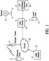
- FIG. 1shows a security system with a remotely programmable activity sensor system in accordance with an implementation.
- FIG. 2shows a simplified block diagram of a remotely programmable activity sensor system in accordance with an implementation.
- FIG. 3shows another simplified block diagram of a remotely programmable activity sensor system in accordance with an implementation.
- FIG. 1shows a security system with a remotely programmable activity sensor system 17 .
- Remotely programmable activity sensor system 17is in wireless contact, for example, with a Wi-Fi router 14 or another wireless communication device.
- Remotely programmable activity sensor system 17also is in wireless contact with a second wireless channel hub 16 , which provides a communication path for remotely programmable activity sensor system 17 to receive commands from a remote source and for remotely programmable activity sensor system 17 to provide status.
- Communication with remotely programmable activity sensor system 17may be accomplished by a local user 15 directly through Wi-Fi router 14 , or by a remote user 12 connected through the Internet, represented by cloud 10 a remote Wi-Fi router 13 to Wi-Fi router 14 .
- Remote user 12can be connected to cloud 10 via a cellphone network, represented by a cell tower 11 , or by another type of wireless network, represented by a Wi-Fi router 13 .
- FIG. 2shows a simplified block diagram of remotely programmable activity sensor system 17 .
- a main activity sensor 30includes a sensor 29 that is, for example, a low power artificial intelligence (AI) based image sensor.
- An image signal processor 28processes signals captured by sensor 29 .
- a video & detection processor 27is used to process video and detect events and information from images in video signals received from image signal processor 28 and captured by sensor 29 .
- Video from video & detection processor 27may be stored in a local storage 25 and/or communicated through a Wi-Fi channel 26 to Wi-Fi channel hub 16 to a local user 15 or through cloud 10 to a remote user for storage or real-time viewing.
- a low power AI controller 22uses a wireless channel 21 to interface with second wireless channel hub 16 .
- Low power AI controller 22also controls a power source and power management block 24 .
- Low power AI controller 22receives data from the second wireless channel. When the data is a wakeup signal, low power AI controller 22 turns on power source and power management block 24 . The main activity sensor 30 is then awakened into full operating mode. If the data is to select a new detection model, low power AI controller 22 will communicate with model library 23 to make the desired library model ready for video & detection processor 27 to check against when processing the captured video detection.
- Wireless channel 21can function as a built-in always-on low power consumption wireless communication channel.
- Sensor 29can function as an always-on low power consumption AI-based image sensor. To save operating power, sensor 29 usually has lower image resolution; nevertheless, sensor 29 works well in detecting motional object. For example, using AI, sensor 29 can train itself to accurately detect certain specific object beside detecting the motion. Initial motion sensing is carried out by always-on sensor 29 .
- remotely programmable activity sensor system 17can provide a highly reliable and accurate motion and object detection with very low power consumption. It provides an extremely low false detection rate.
- AIartificial intelligence
- Low power AI controller 22accessible through second wireless channel 21 , can be programmed for detection activity. This includes selecting a specific object for detection and storing image information for the specific object in model library 23 . Thus, remotely programmable activity sensor system 17 can be programmed to send an alarm when a particular object is detected.
- Second wireless channel 21is implemented, for example, using a low bandwidth, low power consumption, long range wireless media and protocol—such as an independent sideband (ISB) band.
- the carrier frequency of second wireless channel 21can be different from that of Wi-Fi. So, even if the Wi-Fi performance is degraded due to environment or other reason, the second wireless channel 21 can still be in proper operation mode.
- Sensor 29is typically always on using ultra low standby current consumption. However, if an even lower level of power consumption is desired, sensor 29 can be put in a sleep mode and an optional PIR sensor can be added to the circuit to detect motion and trigger sensor 29 to wake up for video capture.
- main activity sensor 17is implemented using an ultra-low power CMOS image sensor with on-chip energy harvesting and power management capability, as is described by Ismail Cevik et al, “An Ultra-Low Power CMOS Image Sensor with On-Chip Energy Harvesting and Power Management Capability”, Sensors 2015, 15, 5531-5554; doi:10.3390/s150305531, available at http:/www.mdpi.com/journal/sensors.
- the discussed 96 ⁇ 96 CMOS pixel arrayconsumes 6.53 uW, with on-chip energy harvesting and power management capability that enables energy autonomous operation at 72.5% duty cycle imaging mode.
- Such low power image sensor due to its energy self-sufficiencycan be operating always-on indefinitely under normal use environment.
- wireless channel 21is implemented using a low-power consumption wireless communication channel such as the ZL70050 Ultra-Low-Power Sub-GHz RF Transceiver by Microsemi, which utilizes 2.75 mA in transmit and 2.4 mA in receive, and has an ultralow sleep current of 10 nA.
- a low-power consumption wireless communication channelcan support 5 mW power-consumption-level standby current with 100% readiness for receiving commands from a remote source. If the readiness duty-cycle is relaxed, for example with 0.2 second on-cycle with 1.8 second off-cycle (i.e. it is being placed in sleep-mode), then the average power consumption can be lowered to around 0.5 mW.
- This power-saving modecan still deliver a command response time (or latency) of near 2 sec, that may still be adequate for non-critical applications such as home-surveillance, while allowing longer battery operating time till next recharge.
- the sensor systemcan capture fast-moving motion events without any lapses such as those caused by wake-up delays present in prior art, because the low power image sensor is always-on.
- the sensor systemcan distinguish the nature and category of the motion-triggering object, such as by a person, an animal, or a mechanical device, unlike in prior-art systems based on PIR (passive infrared) motion sensor.
- PIRpassive infrared
- the main enabler for the low power image sensor's superiority over a PIR motion sensoris due to the fact that its 96 ⁇ 96 pixel array can capture object/event shapes with adequate resolution that allows object analysis to discern the images and determine the category of the motion-triggering object.
- the sensor systemcan be commanded remotely any time, such as for acquiring real-time high-resolution images through awakening parts of the system that are typically idling in sleep-mode for conserving battery power, or for on-demand programming for intelligent and specific type(s) of object detection and recognition, among all other desirable commands.
- FIG. 3shows a simplified block diagram of a remotely programmable activity sensor system 37 that is an alternative embodiment that may be used instead of remotely programmable activity sensor system 17 .
- a main activity sensor 40includes a high resolution sensor 59 that is, for example, a conventional high resolution image sensor.
- An image signal processor 48processes signals captured by high resolution sensor 59 .
- a video & detection processor 47is used to process video and detect events and information from images in video signals received from image signal processor 48 as being captured by high resolution sensor 59 .
- Video from video & detection processor 47may be stored in a local storage 45 and/or communicated through a Wi-Fi channel 46 to Wi-Fi channel hub 16 to a local user 15 or through cloud 10 to a remote user for storage or real-time viewing.
- a low power AI-based sensor 50includes a low power image sensor 49 that is, for example, a low power artificial intelligence (AI) based image sensor (LPAIS).
- a low power AI controller 42uses a wireless channel 41 to interface with second wireless channel hub 16 .
- Low power AI controller 42controls a power source and power management block 44 .
- Low power AI controller 42 and video & detection processor 47can access a model library 43 .
- Wireless channel 41can function as a built-in always-on low power consumption wireless communication channel.
- Sensor 49can function as an always-on low power consumption AI-based image sensor.
- Second wireless channel 41is implemented, for example, using a low bandwidth, low power consumption, long range wireless media and protocol—such as ISB band.
- the carrier frequency of second wireless channel 41can be different from that of Wi-Fi. So, even if the Wi-Fi performance is degraded due to environment or other reason, the second wireless channel 41 can still be in proper operation mode.
- low power image sensor 49has lower image resolution than high resolution sensor 59 ; nevertheless, low power image sensor 49 works well in detecting a motional object. For example, using AI, low power image sensor 49 can train itself to accurately detect certain specific object beside detecting the motion. Initial motion sensing is carried out by the always-on low power image sensor 49 .
- low power image sensor 49being a low power artificial intelligence (AI) based image sensor
- remotely programmable activity sensor system 37can provide a highly reliable and accurate motion and object detection with very low power consumption. It provides an extremely low false detection rate.
- AIartificial intelligence
- Low power AI controller 42accessible through second wireless channel 41 , can be programmed for detection activity. This includes selecting a specific object for detection, image information of which is stored in model library 43 . Thus, remotely programmable activity sensor system 37 can be programmed to send an alarm when a particular object is detected.
- the high resolution sensor 59has higher resolution and consumes more operating power than the low power image sensor 49 .
- High resolution sensor 59usually is in sleep mode when not in full operation. As soon as sensing a motional object, low power image sensor 49 sends a signal to wake up high resolution sensor 59 for high resolution sensing operation.
- a local or remote usercan wake up the high resolution sensor 59 through second wireless communication channel 41 .
- low power AI controller 42is programmed for recognition of a specific object for detection, based on image information which is stored in model library 43 .
- low power image sensor 49detects the presence of the specific object, this triggers high resolution sensor 59 to wake-up and begin capturing images.
- high resolution sensoris fully functional, low power image sensor 49 captures images, so that remotely programmable activity sensor system 37 is always recording events, whether in low resolution or in high resolution.
- the remotely programmable activity sensor system 37provides a highly reliable and accurate motion and object detection with very low power consumption. It provides an extremely low false detection rate.
- low power image sensor 49is implemented using an ultra-low power CMOS image sensor with on-chip energy harvesting and power management capability, as is described by Ismail Cevik et al, “An Ultra-Low Power CMOS Image Sensor with On-Chip Energy Harvesting and Power Management Capability”, Sensors 2015, 15, 5531-5554; doi:10.3390/s150305531, as cited above
- high resolution sensor 59is implemented using a full-resolution image sensor such as the AR0231AT Digital Image Sensor by ON Semiconductor with 1928 ⁇ 1208 active-pixel array, as described above.
- wireless channel 41is implemented using a low-power consumption wireless communication channel such as the ZL70050 Ultra-Low-Power Sub-GHz RF Transceiver by Microsemi.
- a sensor systemcan capture fast-moving motion events without any lapses such as those caused by wake-up delays present in prior art, because the low power image sensor is always-on.
- the sensor systemcan distinguish the nature and category of the motion-triggering object, such as by a person, an animal, or a mechanical device.
- the low power wireless communication channelis either always on or periodically turned-on according to a preset duty cycle such as 0.2 seconds active to 1.8 seconds sleep.
- the sensor systemcan be commanded remotely any time, such as for acquiring real-time high-resolution images through awakening parts of the system that are typically idling in sleep-mode for conserving battery power, or for on-demand programming of intelligent and specific type(s) of object detection and recognition, among all other desirable commands.
Landscapes
- Physics & Mathematics (AREA)
- General Physics & Mathematics (AREA)
- Engineering & Computer Science (AREA)
- Multimedia (AREA)
- Computer Hardware Design (AREA)
- General Engineering & Computer Science (AREA)
- Business, Economics & Management (AREA)
- Emergency Management (AREA)
- Human Computer Interaction (AREA)
- Computer Networks & Wireless Communication (AREA)
- Computer Vision & Pattern Recognition (AREA)
- Closed-Circuit Television Systems (AREA)
Abstract
Description
Claims (15)
Priority Applications (1)
| Application Number | Priority Date | Filing Date | Title |
|---|---|---|---|
| US16/246,368US10832543B2 (en) | 2019-01-11 | 2019-01-11 | Activity sensor |
Applications Claiming Priority (1)
| Application Number | Priority Date | Filing Date | Title |
|---|---|---|---|
| US16/246,368US10832543B2 (en) | 2019-01-11 | 2019-01-11 | Activity sensor |
Publications (2)
| Publication Number | Publication Date |
|---|---|
| US20200226897A1 US20200226897A1 (en) | 2020-07-16 |
| US10832543B2true US10832543B2 (en) | 2020-11-10 |
Family
ID=71517787
Family Applications (1)
| Application Number | Title | Priority Date | Filing Date |
|---|---|---|---|
| US16/246,368ActiveUS10832543B2 (en) | 2019-01-11 | 2019-01-11 | Activity sensor |
Country Status (1)
| Country | Link |
|---|---|
| US (1) | US10832543B2 (en) |
Citations (20)
| Publication number | Priority date | Publication date | Assignee | Title |
|---|---|---|---|---|
| US6735387B1 (en) | 2001-01-10 | 2004-05-11 | Tim Schnell | Motion detector camera |
| US20050285934A1 (en) | 2002-10-15 | 2005-12-29 | Ronald Carter | Automated audio video messaging and answering system |
| US20070103548A1 (en) | 2002-10-15 | 2007-05-10 | Revolutionary Concepts, Inc. | Audio-video communication system for receiving person at entrance |
| US20070103541A1 (en) | 2002-10-15 | 2007-05-10 | Revolutionary Concepts, Inc. | Two-way audio-video communication method for receiving person at entrance |
| US20070103542A1 (en) | 2002-10-15 | 2007-05-10 | Revolutionary Concepts, Inc. | Video communication method for receiving person at entrance |
| US20090278912A1 (en) | 2008-05-11 | 2009-11-12 | Revolutionary Concepts, Inc. | Medical audio/video communications system |
| US20090284595A1 (en) | 2008-05-11 | 2009-11-19 | Revolutionary Concepts, Inc. | Communications and surveillance systems, methods, and apparatus |
| US20090284578A1 (en) | 2008-05-11 | 2009-11-19 | Revolutionary Concepts, Inc. | Real estate communications and monitoring systems and methods for use by real estate agents |
| US7710457B2 (en) | 2001-01-10 | 2010-05-04 | Ip Holdings, Inc. | Motion detector camera having a flash |
| US8410930B2 (en) | 2010-04-15 | 2013-04-02 | The Chamberlain Group, Inc. | Method and apparatus pertaining to barrier movement controllers and employing a camera and a wireless transmitter |
| US20130201360A1 (en)* | 2012-02-03 | 2013-08-08 | Samsung Electronics Co., Ltd. | Method of changing an operation mode of a camera image sensor |
| US9176608B1 (en)* | 2011-06-27 | 2015-11-03 | Amazon Technologies, Inc. | Camera based sensor for motion detection |
| US20160094787A1 (en) | 2014-09-30 | 2016-03-31 | Qualcomm Incorporated | Event based computer vision computation |
| US20160093180A1 (en) | 2014-09-30 | 2016-03-31 | The Chamberlain Group, Inc. | Garage monitor |
| US20160094814A1 (en) | 2014-09-30 | 2016-03-31 | Qualcomm Incorporated | Low-power always-on face detection, tracking, recognition and/or analysis using events-based vision sensor |
| US9390032B1 (en)* | 2012-06-27 | 2016-07-12 | Amazon Technologies, Inc. | Gesture camera configurations |
| US9683391B2 (en) | 2013-03-15 | 2017-06-20 | August Home, Inc. | Intelligent door lock system including intelligent security system with reduced latency |
| US9756233B2 (en) | 2014-03-27 | 2017-09-05 | The Chamberlain Group, Inc. | Barrier operator control of a camera |
| US20170353699A1 (en)* | 2016-06-01 | 2017-12-07 | Pixart Imaging Inc. | Surveillance system and operation method thereof |
| US20180227507A1 (en)* | 2017-02-03 | 2018-08-09 | Ring Inc. | Audio/Video Recording and Communication Devices with Multiple Cameras for Superimposing Image Data |
- 2019
- 2019-01-11USUS16/246,368patent/US10832543B2/enactiveActive
Patent Citations (66)
| Publication number | Priority date | Publication date | Assignee | Title |
|---|---|---|---|---|
| US7593632B2 (en) | 2001-01-10 | 2009-09-22 | Ip Holdings, Inc. | Motion detector camera |
| US6768868B1 (en) | 2001-01-10 | 2004-07-27 | Ip Holdings, Inc. | Motion detector camera |
| US6834162B1 (en) | 2001-01-10 | 2004-12-21 | Ip Holdings, Inc. | Motion detector camera |
| US6735387B1 (en) | 2001-01-10 | 2004-05-11 | Tim Schnell | Motion detector camera |
| US7149422B2 (en) | 2001-01-10 | 2006-12-12 | Ip Holdings, Inc. | Motion detector camera |
| US8895926B2 (en) | 2001-01-10 | 2014-11-25 | Ip Holdings, Inc. | Motion detector camera |
| US8350915B2 (en) | 2001-01-10 | 2013-01-08 | Ip Holdings, Inc. | Motion detector camera |
| US8254776B2 (en) | 2001-01-10 | 2012-08-28 | Ip Holdings, Inc. | Motion detector camera |
| US7873266B2 (en) | 2001-01-10 | 2011-01-18 | Ip Holdings, Inc. | Motion detector camera |
| US7308196B2 (en) | 2001-01-10 | 2007-12-11 | Ip Holdings, Inc. | Motion detector camera |
| US7710457B2 (en) | 2001-01-10 | 2010-05-04 | Ip Holdings, Inc. | Motion detector camera having a flash |
| US20170078624A1 (en) | 2002-10-15 | 2017-03-16 | Eyetalk365, Llc | Communication and Monitoring System |
| US9635323B2 (en) | 2002-10-15 | 2017-04-25 | Eyetalk365, Llc | Communication and monitoring system |
| US20200007826A1 (en) | 2002-10-15 | 2020-01-02 | Eyetalk365, Llc | Communication and Monitoring System |
| US10523906B2 (en) | 2002-10-15 | 2019-12-31 | Eyetalk365, Llc | Communication and monitoring system |
| US20190149776A1 (en) | 2002-10-15 | 2019-05-16 | Eyetalk365, Llc | Communication and Monitoring System |
| US20080117299A1 (en) | 2002-10-15 | 2008-05-22 | Revolutionary Concepts, Inc. | Communication and monitoring system |
| US20070103542A1 (en) | 2002-10-15 | 2007-05-10 | Revolutionary Concepts, Inc. | Video communication method for receiving person at entrance |
| US8139098B2 (en) | 2002-10-15 | 2012-03-20 | Revolutionary Concepts, Inc. | Video communication method for receiving person at entrance |
| US8144183B2 (en) | 2002-10-15 | 2012-03-27 | Revolutionary Concepts, Inc. | Two-way audio-video communication method for receiving person at entrance |
| US8144184B2 (en) | 2002-10-15 | 2012-03-27 | Revolutionary Concepts, Inc. | Detection and viewing system |
| US8154581B2 (en) | 2002-10-15 | 2012-04-10 | Revolutionary Concepts, Inc. | Audio-video communication system for receiving person at entrance |
| US8164614B2 (en) | 2002-10-15 | 2012-04-24 | Revolutionary Concepts, Inc. | Communication and monitoring system |
| US20070103541A1 (en) | 2002-10-15 | 2007-05-10 | Revolutionary Concepts, Inc. | Two-way audio-video communication method for receiving person at entrance |
| US20070103548A1 (en) | 2002-10-15 | 2007-05-10 | Revolutionary Concepts, Inc. | Audio-video communication system for receiving person at entrance |
| US10200660B2 (en) | 2002-10-15 | 2019-02-05 | Eyetalk365, Llc | Communication and monitoring system |
| US10097796B2 (en) | 2002-10-15 | 2018-10-09 | Eyetalk365, Llc | Communication and monitoring system |
| US7193644B2 (en) | 2002-10-15 | 2007-03-20 | Revolutionary Concepts, Inc. | Automated audio video messaging and answering system |
| US20150222852A1 (en) | 2002-10-15 | 2015-08-06 | Ronald Carter | Communication and Monitoring System |
| US20150312534A1 (en) | 2002-10-15 | 2015-10-29 | Ronald Carter | Communication and Monitoring System |
| US10097797B2 (en) | 2002-10-15 | 2018-10-09 | Eyetalk365, Llc | Communication and monitoring system |
| US9924141B2 (en) | 2002-10-15 | 2018-03-20 | Eyetalk365, Llc | Communication and monitoring system |
| US20160094816A1 (en) | 2002-10-15 | 2016-03-31 | Eyetalk365, Llc | Communication and Monitoring System |
| US9866802B2 (en) | 2002-10-15 | 2018-01-09 | Eyetalk365, Llc | Communication and monitoring system |
| US9706178B2 (en) | 2002-10-15 | 2017-07-11 | Eyetalk365, Llc | Communication and monitoring system |
| US20160105650A1 (en) | 2002-10-15 | 2016-04-14 | Eyetalk365, Llc | Communication and Monitoring System |
| US9648290B2 (en) | 2002-10-15 | 2017-05-09 | Eyetalk365, Llc | Communication and monitoring system |
| US9414030B2 (en) | 2002-10-15 | 2016-08-09 | Eyetalk365, Llc | Communication and monitoring system |
| US9432638B2 (en) | 2002-10-15 | 2016-08-30 | Eyetalk365, Llc | Communication and monitoring system |
| US9485478B2 (en) | 2002-10-15 | 2016-11-01 | Eyetalk365, Llc | Communication and monitoring system |
| US9516284B2 (en) | 2002-10-15 | 2016-12-06 | Eyetalk365, Llc | Communication and monitoring system |
| US20160360162A1 (en) | 2002-10-15 | 2016-12-08 | Eyetalk365, Llc | Communication and Monitoring System |
| US20160360163A1 (en) | 2002-10-15 | 2016-12-08 | Eyetalk365, Llc | Communication and Monitoring System |
| US20160366375A1 (en) | 2002-10-15 | 2016-12-15 | Eyetalk365, Llc | Communication and Monitoring System |
| US20160366374A1 (en) | 2002-10-15 | 2016-12-15 | Eyetalk365, Llc | Communication and Monitoring System |
| US9554090B1 (en) | 2002-10-15 | 2017-01-24 | Eyetalk365, Llc | Communication and monitoring system |
| US20170048489A1 (en) | 2002-10-15 | 2017-02-16 | Eyetalk365, Llc | Communication and Monitoring System |
| US20170048497A1 (en) | 2002-10-15 | 2017-02-16 | Eyetalk365, Llc | Communication and Monitoring System |
| US20050285934A1 (en) | 2002-10-15 | 2005-12-29 | Ronald Carter | Automated audio video messaging and answering system |
| US20170078625A1 (en) | 2002-10-15 | 2017-03-16 | Eyetalk365, Llc | Communication and Monitoring System |
| US20170085842A1 (en) | 2002-10-15 | 2017-03-23 | Eyetalk365, Llc | Communication and Monitoring System |
| US20080136908A1 (en) | 2002-10-15 | 2008-06-12 | Revolutionary Concepts, Inc. | Detection and viewing system |
| US20090278912A1 (en) | 2008-05-11 | 2009-11-12 | Revolutionary Concepts, Inc. | Medical audio/video communications system |
| US20090284595A1 (en) | 2008-05-11 | 2009-11-19 | Revolutionary Concepts, Inc. | Communications and surveillance systems, methods, and apparatus |
| US20090284578A1 (en) | 2008-05-11 | 2009-11-19 | Revolutionary Concepts, Inc. | Real estate communications and monitoring systems and methods for use by real estate agents |
| US8410930B2 (en) | 2010-04-15 | 2013-04-02 | The Chamberlain Group, Inc. | Method and apparatus pertaining to barrier movement controllers and employing a camera and a wireless transmitter |
| US9176608B1 (en)* | 2011-06-27 | 2015-11-03 | Amazon Technologies, Inc. | Camera based sensor for motion detection |
| US20130201360A1 (en)* | 2012-02-03 | 2013-08-08 | Samsung Electronics Co., Ltd. | Method of changing an operation mode of a camera image sensor |
| US9390032B1 (en)* | 2012-06-27 | 2016-07-12 | Amazon Technologies, Inc. | Gesture camera configurations |
| US9683391B2 (en) | 2013-03-15 | 2017-06-20 | August Home, Inc. | Intelligent door lock system including intelligent security system with reduced latency |
| US9756233B2 (en) | 2014-03-27 | 2017-09-05 | The Chamberlain Group, Inc. | Barrier operator control of a camera |
| US20160094787A1 (en) | 2014-09-30 | 2016-03-31 | Qualcomm Incorporated | Event based computer vision computation |
| US20160093180A1 (en) | 2014-09-30 | 2016-03-31 | The Chamberlain Group, Inc. | Garage monitor |
| US20160094814A1 (en) | 2014-09-30 | 2016-03-31 | Qualcomm Incorporated | Low-power always-on face detection, tracking, recognition and/or analysis using events-based vision sensor |
| US20170353699A1 (en)* | 2016-06-01 | 2017-12-07 | Pixart Imaging Inc. | Surveillance system and operation method thereof |
| US20180227507A1 (en)* | 2017-02-03 | 2018-08-09 | Ring Inc. | Audio/Video Recording and Communication Devices with Multiple Cameras for Superimposing Image Data |
Non-Patent Citations (5)
| Title |
|---|
| AR0231AT 1/2.7-inch 23 Mp Digital Image Sensor, Advance Information, Semiconductor Components Industries, LLC, 2017, Publication Order Number: AR0231/3, Sep. 2017-Rev. P6. |
| AR0231AT 1/2.7-inch 23 Mp Digital Image Sensor, Advance Information, Semiconductor Components Industries, LLC, 2017, Publication Order Number: AR0231/3, Sep. 2017—Rev. P6. |
| Ismail Cervik, et al., An Ultra-Low Power CMOS Image Sensor with On-Chip Energy Harvesting and Power Management Capability, Sensors 2015, 15, 5531-5554; doi:10.3390/s150305531, ISSN 1424-8220, Mar. 2015. |
| Stacey Higginbothamarchive Page; Qualcomm Wants Your Smartphone to Have Energy-Efficient Eyes; Mar. 29, 2017; https://www.technologyreview.com/2017/03/29/243161/qualcomm-wants-your-smartphone-to-have-energy-efficient-eyes/. |
| ZL70550 Ultra-Low-Power Sub-GHz RF Transceiver, Microsemi Corporation, ZL70550-PP / 154044-4 / Jun. 17, 2017. |
Also Published As
| Publication number | Publication date |
|---|---|
| US20200226897A1 (en) | 2020-07-16 |
Similar Documents
| Publication | Publication Date | Title |
|---|---|---|
| US12279136B2 (en) | Operating wireless devices and image data systems | |
| US7507946B2 (en) | Network sensor system and protocol | |
| US20040212678A1 (en) | Low power motion detection system | |
| US20080084836A1 (en) | Low power wireless communication method | |
| CN113938598A (en) | Surveillance camera wake-up method, device, device and medium | |
| US9713084B2 (en) | Lost access point power save mode for WiFi devices | |
| CN206442461U (en) | Low-power consumption and quick-response monitoring device | |
| US20130336185A1 (en) | Apparatus and method for recharge-triggered wake-up for power management in wireless sensor networks | |
| US20190357138A1 (en) | Secondary processor management allowing deep sleep of primary processor | |
| US10051172B2 (en) | RF front end power control for low power RF devices | |
| TWI603619B (en) | A low power consumption and fast response and low false alarm rate of the video surveillance system | |
| CN117998196A (en) | Video acquisition method, apparatus and computer readable storage medium | |
| US10832543B2 (en) | Activity sensor | |
| US20190306468A1 (en) | Wireless monitoring system and power saving method of wireless monitor | |
| CN113259588A (en) | Low-power-consumption mobile object detection system and method | |
| CN112504467A (en) | Passenger flow analysis apparatus and control method thereof | |
| CN116405749B (en) | Door lock monitoring device, door lock system and implementation method for low-power-consumption continuous video recording | |
| CN110267019A (en) | A kind of split type low-power consumption monitoring system | |
| US12445577B2 (en) | Operating wireless devices and image data systems | |
| US12265437B2 (en) | Network connected device energy conservation | |
| WO2024212633A1 (en) | Electronic device and operation method therefor, and storage medium | |
| CN120091223A (en) | Battery camera and recording method thereof, video monitoring system and storage medium | |
| KR20250094630A (en) | Low-Power Missing Prevention Device with BLE Beacon and AI-Based Real-Time Risk Detection, and Its Operation Method | |
| CN115601893A (en) | Doorbell equipment control method and device, storage medium and electronic device | |
| CN120091221A (en) | Battery camera and low power consumption mode control method thereof, and computer readable storage medium |
Legal Events
| Date | Code | Title | Description |
|---|---|---|---|
| FEPP | Fee payment procedure | Free format text:ENTITY STATUS SET TO UNDISCOUNTED (ORIGINAL EVENT CODE: BIG.); ENTITY STATUS OF PATENT OWNER: LARGE ENTITY | |
| FEPP | Fee payment procedure | Free format text:ENTITY STATUS SET TO SMALL (ORIGINAL EVENT CODE: SMAL); ENTITY STATUS OF PATENT OWNER: LARGE ENTITY | |
| AS | Assignment | Owner name:THE CHAMBERLAIN GROUP, INC., ILLINOIS Free format text:ASSIGNMENT OF ASSIGNORS INTEREST;ASSIGNORS:CHENG, FRED;YAU, HERMAN;REEL/FRAME:049656/0121 Effective date:20190701 | |
| FEPP | Fee payment procedure | Free format text:ENTITY STATUS SET TO UNDISCOUNTED (ORIGINAL EVENT CODE: BIG.); ENTITY STATUS OF PATENT OWNER: LARGE ENTITY | |
| FEPP | Fee payment procedure | Free format text:PETITION RELATED TO MAINTENANCE FEES GRANTED (ORIGINAL EVENT CODE: PTGR); ENTITY STATUS OF PATENT OWNER: LARGE ENTITY | |
| STPP | Information on status: patent application and granting procedure in general | Free format text:PUBLICATIONS -- ISSUE FEE PAYMENT VERIFIED | |
| STCF | Information on status: patent grant | Free format text:PATENTED CASE | |
| CC | Certificate of correction | ||
| AS | Assignment | Owner name:ARES CAPITAL CORPORATION, AS COLLATERAL AGENT, NEW YORK Free format text:SECOND LIEN PATENT SECURITY AGREEMENT;ASSIGNORS:THE CHAMBERLAIN GROUP LLC;SYSTEMS, LLC;REEL/FRAME:058015/0001 Effective date:20211103 Owner name:WELLS FARGO BANK, NATIONAL ASSOCIATION, AS COLLATERAL AGENT, COLORADO Free format text:FIRST LIEN PATENT SECURITY AGREEMENT;ASSIGNORS:THE CHAMBERLAIN GROUP LLC;SYSTEMS, LLC;REEL/FRAME:058014/0931 Effective date:20211103 | |
| AS | Assignment | Owner name:THE CHAMBLERLAIN GROUP LLC, ILLINOIS Free format text:CONVERSION;ASSIGNOR:THE CHAMBERLAIN GROUP, INC.;REEL/FRAME:058738/0305 Effective date:20210805 | |
| AS | Assignment | Owner name:THE CHAMBERLAIN GROUP LLC, ILLINOIS Free format text:CONVERSION;ASSIGNOR:THE CHAMBERLAIN GROUP, INC.;REEL/FRAME:060379/0207 Effective date:20210805 | |
| AS | Assignment | Owner name:SYSTEMS, LLC, ILLINOIS Free format text:NOTICE OF TERMINATION AND RELEASE OF SECURITY INTEREST IN PATENTS;ASSIGNOR:ARES CAPITAL CORPORATION, AS COLLATERAL AGENT;REEL/FRAME:066374/0749 Effective date:20240126 Owner name:THE CHAMBERLAIN GROUP LLC, ILLINOIS Free format text:NOTICE OF TERMINATION AND RELEASE OF SECURITY INTEREST IN PATENTS;ASSIGNOR:ARES CAPITAL CORPORATION, AS COLLATERAL AGENT;REEL/FRAME:066374/0749 Effective date:20240126 | |
| MAFP | Maintenance fee payment | Free format text:PAYMENT OF MAINTENANCE FEE, 4TH YEAR, LARGE ENTITY (ORIGINAL EVENT CODE: M1551); ENTITY STATUS OF PATENT OWNER: LARGE ENTITY Year of fee payment:4 |