US10830130B2 - Geared turbofan with three turbines all counter-rotating - Google Patents
Geared turbofan with three turbines all counter-rotatingDownload PDFInfo
- Publication number
- US10830130B2 US10830130B2US15/843,012US201715843012AUS10830130B2US 10830130 B2US10830130 B2US 10830130B2US 201715843012 AUS201715843012 AUS 201715843012AUS 10830130 B2US10830130 B2US 10830130B2
- Authority
- US
- United States
- Prior art keywords
- turbine
- rotor
- engine
- fan
- compressor
- Prior art date
- Legal status (The legal status is an assumption and is not a legal conclusion. Google has not performed a legal analysis and makes no representation as to the accuracy of the status listed.)
- Active, expires
Links
- 230000003068static effectEffects0.000claimsdescription7
- 239000007789gasSubstances0.000description12
- 239000000446fuelSubstances0.000description7
- 238000002485combustion reactionMethods0.000description4
- 239000000463materialSubstances0.000description4
- 238000005266castingMethods0.000description2
- 238000012986modificationMethods0.000description2
- 230000004048modificationEffects0.000description2
- 238000011144upstream manufacturingMethods0.000description2
- 239000013078crystalSubstances0.000description1
Images


Classifications
- F—MECHANICAL ENGINEERING; LIGHTING; HEATING; WEAPONS; BLASTING
- F02—COMBUSTION ENGINES; HOT-GAS OR COMBUSTION-PRODUCT ENGINE PLANTS
- F02C—GAS-TURBINE PLANTS; AIR INTAKES FOR JET-PROPULSION PLANTS; CONTROLLING FUEL SUPPLY IN AIR-BREATHING JET-PROPULSION PLANTS
- F02C3/00—Gas-turbine plants characterised by the use of combustion products as the working fluid
- F02C3/04—Gas-turbine plants characterised by the use of combustion products as the working fluid having a turbine driving a compressor
- F02C3/107—Gas-turbine plants characterised by the use of combustion products as the working fluid having a turbine driving a compressor with two or more rotors connected by power transmission
- F—MECHANICAL ENGINEERING; LIGHTING; HEATING; WEAPONS; BLASTING
- F01—MACHINES OR ENGINES IN GENERAL; ENGINE PLANTS IN GENERAL; STEAM ENGINES
- F01D—NON-POSITIVE DISPLACEMENT MACHINES OR ENGINES, e.g. STEAM TURBINES
- F01D1/00—Non-positive-displacement machines or engines, e.g. steam turbines
- F01D1/02—Non-positive-displacement machines or engines, e.g. steam turbines with stationary working-fluid guiding means and bladed or like rotor, e.g. multi-bladed impulse steam turbines
- F01D1/10—Non-positive-displacement machines or engines, e.g. steam turbines with stationary working-fluid guiding means and bladed or like rotor, e.g. multi-bladed impulse steam turbines having two or more stages subjected to working-fluid flow without essential intermediate pressure change, i.e. with velocity stages
- F—MECHANICAL ENGINEERING; LIGHTING; HEATING; WEAPONS; BLASTING
- F01—MACHINES OR ENGINES IN GENERAL; ENGINE PLANTS IN GENERAL; STEAM ENGINES
- F01D—NON-POSITIVE DISPLACEMENT MACHINES OR ENGINES, e.g. STEAM TURBINES
- F01D1/00—Non-positive-displacement machines or engines, e.g. steam turbines
- F01D1/24—Non-positive-displacement machines or engines, e.g. steam turbines characterised by counter-rotating rotors subjected to same working fluid stream without intermediate stator blades or the like
- F01D1/26—Non-positive-displacement machines or engines, e.g. steam turbines characterised by counter-rotating rotors subjected to same working fluid stream without intermediate stator blades or the like traversed by the working-fluid substantially axially
- F—MECHANICAL ENGINEERING; LIGHTING; HEATING; WEAPONS; BLASTING
- F01—MACHINES OR ENGINES IN GENERAL; ENGINE PLANTS IN GENERAL; STEAM ENGINES
- F01D—NON-POSITIVE DISPLACEMENT MACHINES OR ENGINES, e.g. STEAM TURBINES
- F01D15/00—Adaptations of machines or engines for special use; Combinations of engines with devices driven thereby
- F01D15/12—Combinations with mechanical gearing
- F—MECHANICAL ENGINEERING; LIGHTING; HEATING; WEAPONS; BLASTING
- F01—MACHINES OR ENGINES IN GENERAL; ENGINE PLANTS IN GENERAL; STEAM ENGINES
- F01D—NON-POSITIVE DISPLACEMENT MACHINES OR ENGINES, e.g. STEAM TURBINES
- F01D5/00—Blades; Blade-carrying members; Heating, heat-insulating, cooling or antivibration means on the blades or the members
- F01D5/02—Blade-carrying members, e.g. rotors
- F01D5/06—Rotors for more than one axial stage, e.g. of drum or multiple disc type; Details thereof, e.g. shafts, shaft connections
- F—MECHANICAL ENGINEERING; LIGHTING; HEATING; WEAPONS; BLASTING
- F02—COMBUSTION ENGINES; HOT-GAS OR COMBUSTION-PRODUCT ENGINE PLANTS
- F02C—GAS-TURBINE PLANTS; AIR INTAKES FOR JET-PROPULSION PLANTS; CONTROLLING FUEL SUPPLY IN AIR-BREATHING JET-PROPULSION PLANTS
- F02C3/00—Gas-turbine plants characterised by the use of combustion products as the working fluid
- F02C3/04—Gas-turbine plants characterised by the use of combustion products as the working fluid having a turbine driving a compressor
- F02C3/06—Gas-turbine plants characterised by the use of combustion products as the working fluid having a turbine driving a compressor the compressor comprising only axial stages
- F02C3/067—Gas-turbine plants characterised by the use of combustion products as the working fluid having a turbine driving a compressor the compressor comprising only axial stages having counter-rotating rotors
- F—MECHANICAL ENGINEERING; LIGHTING; HEATING; WEAPONS; BLASTING
- F02—COMBUSTION ENGINES; HOT-GAS OR COMBUSTION-PRODUCT ENGINE PLANTS
- F02C—GAS-TURBINE PLANTS; AIR INTAKES FOR JET-PROPULSION PLANTS; CONTROLLING FUEL SUPPLY IN AIR-BREATHING JET-PROPULSION PLANTS
- F02C3/00—Gas-turbine plants characterised by the use of combustion products as the working fluid
- F02C3/04—Gas-turbine plants characterised by the use of combustion products as the working fluid having a turbine driving a compressor
- F02C3/06—Gas-turbine plants characterised by the use of combustion products as the working fluid having a turbine driving a compressor the compressor comprising only axial stages
- F02C3/073—Gas-turbine plants characterised by the use of combustion products as the working fluid having a turbine driving a compressor the compressor comprising only axial stages the compressor and turbine stages being concentric
- F—MECHANICAL ENGINEERING; LIGHTING; HEATING; WEAPONS; BLASTING
- F05—INDEXING SCHEMES RELATING TO ENGINES OR PUMPS IN VARIOUS SUBCLASSES OF CLASSES F01-F04
- F05D—INDEXING SCHEME FOR ASPECTS RELATING TO NON-POSITIVE-DISPLACEMENT MACHINES OR ENGINES, GAS-TURBINES OR JET-PROPULSION PLANTS
- F05D2220/00—Application
- F05D2220/30—Application in turbines
- F05D2220/32—Application in turbines in gas turbines
- F—MECHANICAL ENGINEERING; LIGHTING; HEATING; WEAPONS; BLASTING
- F05—INDEXING SCHEMES RELATING TO ENGINES OR PUMPS IN VARIOUS SUBCLASSES OF CLASSES F01-F04
- F05D—INDEXING SCHEME FOR ASPECTS RELATING TO NON-POSITIVE-DISPLACEMENT MACHINES OR ENGINES, GAS-TURBINES OR JET-PROPULSION PLANTS
- F05D2250/00—Geometry
- F05D2250/40—Movement of components
- F05D2250/44—Movement of components by counter rotation
- F—MECHANICAL ENGINEERING; LIGHTING; HEATING; WEAPONS; BLASTING
- F05—INDEXING SCHEMES RELATING TO ENGINES OR PUMPS IN VARIOUS SUBCLASSES OF CLASSES F01-F04
- F05D—INDEXING SCHEME FOR ASPECTS RELATING TO NON-POSITIVE-DISPLACEMENT MACHINES OR ENGINES, GAS-TURBINES OR JET-PROPULSION PLANTS
- F05D2260/00—Function
- F05D2260/40—Transmission of power
- F05D2260/403—Transmission of power through the shape of the drive components
- F05D2260/4031—Transmission of power through the shape of the drive components as in toothed gearing
- F05D2260/40311—Transmission of power through the shape of the drive components as in toothed gearing of the epicyclical, planetary or differential type
Definitions
- This applicationrelates to a gas turbine having three turbine sections, with one of the turbine sections driving a fan through a gear change mechanism.
- Gas turbine enginestypically include a compressor section compressing air and delivering the compressed air into a combustion section.
- the airis mixed with fuel and combusted, and the product of that combustion passes downstream over turbine rotors.
- a highest pressure turbinerotates a highest pressure compressor.
- An intermediate pressure turbinerotates a lower pressure compressor, and a third turbine section is a fan drive turbine which drives the fan.
- a gas turbine enginecomprises a fan rotor, a first compressor rotor and a second compressor rotor.
- the second compressor rotorcompresses air to a higher pressure than the first compressor rotor.
- a first turbine rotoris configured to drive the second compressor rotor and a second turbine rotor.
- the second turbineis configured to drive the first compressor rotor.
- a fan drive turbineis positioned downstream of the second turbine rotor and drives the fan rotor through a gear reduction.
- the first compressor rotor and the second turbine rotorare configured to rotate as an intermediate speed spool.
- the second compressor rotor and the first turbine rotorare configured to rotate together as a high speed spool.
- the high speed spool and the fan drive turbineare configured to rotate in the same first direction.
- the intermediate speed spoolis configured to rotate in an opposed, second direction.
- the fan rotoris driven by the gear reduction to rotate in the second direction.
- a power density of the engineis greater than or equal to about 1.5 lbs/in 3 , and less than or equal to about 5.5 lbf/in 3 .
- the power densityis defined as a ratio of thrust produced by the engine expressed in pounds force to a volume of a turbine section incorporating each of the first turbine rotor, the second turbine rotor and the fan drive turbine rotor, expressed in cubic inches.
- the ratiois greater than or equal to about 2.0.
- the ratiois greater than or equal to about 4.0.
- the thrustis sea level take-off flat-rated static thrust.
- the fan rotoris configured to deliver a portion of air into a bypass duct and a portion of air into the first compressor rotor as core flow.
- a mid-turbine frameis positioned between the first and second turbine rotors.
- a turning vaneis positioned between the second turbine rotor and the fan drive turbine.
- a mid-turbine frameis positioned between the first and second turbine rotors.
- a power density of the engineis greater than or equal to about 1.5 lbs/in 3 , and less than or equal to about 5.5 lbf/in 3 .
- the ratiois greater than or equal to about 2.0.
- the fan rotoris configured to deliver a portion of air into a bypass duct and a portion of air into the first compressor rotor as core flow.
- the fan rotoris configured to deliver a portion of air into a bypass duct and a portion of air into the first compressor rotor as core flow.
- a turning vaneis positioned between the second turbine rotor and the fan drive turbine.
- a gas turbine enginecomprises a fan rotor, a first compressor rotor and a second compressor rotor.
- the second compressor rotorcompresses air to a higher pressure than the first compressor rotor.
- a first turbine rotoris configured to drive the second compressor rotor and a second turbine rotor.
- the second turbineis configured to drive the first compressor rotor.
- a fan drive turbineis positioned downstream of the second turbine rotor, and is configured to drive the fan rotor through a gear reduction.
- the first compressor rotor and the second turbine rotorrotate as an intermediate speed spool.
- the second compressor rotor and the first turbine rotorrotate together as a high speed spool.
- the high speed spool and the fan drive turbineare configured to rotate in the same, first direction, and the intermediate speed spool is configured to rotate in an opposed, second direction.
- the fan rotoris driven by the speed reduction to rotate in the opposed second direction.
- a power density of the engineis greater than or equal to about 1.5 lbf/in 3 , and less than or equal to about 5.5 lbf/in 3 .
- the power densityis defined as a ratio of thrust produced by the engine expressed in pounds force to a volume of a turbine section incorporating each of the first turbine rotor, the second turbine rotor and the fan drive turbine rotor, expressed in cubic inches.
- the ratiois greater than or equal to about 2.0.
- the ratiois greater than or equal to about 4.0.
- the thrustis sea level take-off flat-rated static thrust.
- FIG. 1schematically shows a gas turbine engine.
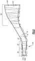
- FIG. 2shows how a volume of the turbine section can be calculated.
- a gas turbine engine 20is illustrated in FIG. 1 , and incorporates a fan 22 driven through a gear reduction 24 .
- the gear reduction 24is driven with a low speed spool 25 by a fan/gear drive turbine (“FGDT”) 26 .
- Airis delivered from the fan as bypass air B, and into a low pressure compressor 30 as core air C.
- the air compressed by the low pressure compressor 30passes downstream into a high pressure compressor 36 , and then into a combustion section 28 . From the combustion section 28 , gases pass across a high pressure turbine 40 , low pressure turbine 34 , and fan/gear drive turbine 26 .
- a plurality of vanes and stators 50may be mounted between the several turbine sections.
- the low pressure compressor 30rotates with an intermediate pressure spool 32 and the low pressure turbine 34 in a first (“ ⁇ ”) direction.
- the fan drive turbine 26rotates with a shaft 25 in a second, opposite (“+”) direction as the intermediate pressure spool 32 .
- the speed change gear 24may cause the fan 22 to rotate in the first (“ ⁇ ”) direction.
- the fan rotating in the opposite directionwould come within the scope of this invention.
- a star gear arrangementmay be utilized for the fan to rotate in an opposite direction as to the fan/gear drive turbine 26 .
- a planetary gear arrangementmay be utilized in the illustrated embodiment, wherein the two rotate in the same direction.
- the high pressure compressor 36rotates with a spool 38 and is driven by a high pressure turbine 40 in the second direction (“+”).
- turning vanes 150may be positioned intermediate the high pressure turbine 40 , and low pressure turbine 34 , and also between the low pressure turbine 34 and the fan drive turbine 26 .
- the air turning anglesare not great with the counter-rotating turbines widely spaced turning vanes may be incorporated into the mid-turbine frame struts themselves, where these struts exist, to provide structure to mount bearings for supporting the spools and shafts.
- the vanesmay be separate from a mid-turbine frame struts and may be a separate row of stators providing precise air flow angles to the rotating turbine stage behind it.
- a vane 50is positioned to direct the gas flow into the high pressure turbine 40 .
- Vane 50may be a highly cambered vane.
- the fan drive turbine 26 in this arrangementcan operate at a higher speed than other fan drive turbine arrangements.
- the fan drive turbinecan have shrouded blades, which provides design freedom.
- the low pressure compressormay have more than three stages.
- the fan drive turbinehas at least two, and up to six stages.
- the high pressure turbine as illustratedmay have one or two stages, and the low pressure turbine may have one or two stages.
- the above featuresachieve a more compact turbine section volume relative to the prior art, including both the high and low pressure turbines.
- a range of materialscan be selected.
- the volumecan be reduced through the use of more expensive and more exotic engineered materials, or alternatively, lower priced materials can be utilized.
- the first rotating blade of the fan drive turbinecan be a directionally solidified casting blade, a single crystal casting blade or a hollow, internally cooled blade. All three embodiments will change the turbine volume to be dramatically smaller than the prior art by increasing low pressure turbine speed.
- a power densitywhich may be defined as thrust in pounds force produced divided by the volume of the entire turbine section, may be optimized.
- the volume of the turbine sectionmay be defined by an inlet of a first turbine vane in the high pressure turbine to the exit of the last rotating airfoil in the fan/gear drive turbine 26 , and may be expressed in cubic inches.
- the static thrust at the engine's flat rated Sea Level Takeoff condition divided by a turbine section volumeis defined as power density.
- the sea level take-off flat-rated static thrustmay be defined in pounds force, while the volume may be the volume from the annular inlet of the first turbine vane in the high pressure turbine to the annular exit of the downstream end of the last rotor section in the fan drive turbine.
- the maximum thrustmay be sea level take-off thrust “SLTO thrust” which is commonly defined as the flat-rated static thrust produced by the turbofan at sea-level.
- the volume V of the turbine sectionmay be best understood from FIG. 2 .
- the high pressure turbineis illustrated at 40 , the low pressure turbine at 34 and the fan drive turbine at 26 .
- the volume Vis illustrated by dashed line, and extends from an inner periphery I to an outer periphery O.
- the inner peripheryis somewhat defined by the flowpath of the rotors, but also by the inner platform flow paths of vanes.
- the outer peripheryis defined by the stator vanes and outer air seal structures along the flowpath.
- the volumeextends from a most upstream 400 end of the most upstream blade 410 in the high pressure turbine section 40 , typically its leading edge, and to the most downstream edge 401 of the last rotating airfoil 412 in the fan drive turbine section 26 . Typically, this will be the trailing edge of that airfoil 412 .
- Mid-turbine frames and valves as illustrated in FIG. 1may be included.
- Thrust SLTO Turbine section volume from Thrust/turbine section Engine(lbf) the Inlet volume (lbf/in 3 ) 1 17,000 3,859 4.41 2 23,300 5,330 4.37 3 29,500 6,745 4.37 4 33,000 6,745 4.84 5 96,500 31,086 3.10 6 96,500 62,172 1.55 7 96,500 46,629 2.07 8 37,098 6,745 5.50
- the power densitywould be greater than or equal to about 1.5 lbf/in 3 . More narrowly, the power density would be greater than or equal to about 2.0 lbf/in 3 .
- the power densitywould be greater than or equal to about 3.0 lbf/in 3 .
- the power densityis greater than or equal to about 4.0 lbf/in 3 .
- the power densityis less than or equal to about 5.5 lbf/in 3 .
- the engine 20 in one exampleis a high-bypass geared aircraft engine.
- the bypass ratiois the amount of air delivered into bypass path B divided by the amount of air into core path C.
- the engine 20 bypass ratiois greater than about six (6), with an example embodiment being greater than ten (10)
- the geared architecture 24is an epicyclic gear train, such as a star of planetary gear system or other gear system, with a gear reduction ratio of greater than about 2.3 and the fan/gear drive turbine section 26 has a pressure ratio that is greater than about 5.
- the engine 20 bypass ratiois greater than about ten (10:1)
- the fan diameteris significantly larger than that of the low pressure compressor section 30
- the fan/gear drive turbine section 26has a pressure ratio that is greater than about 5:1.
- the high pressure turbine section 40may have two or fewer stages.
- the fan/gear drive turbine section 26in some embodiments, has between two and six stages. Further the fan/gear drive turbine section 26 pressure ratio is total pressure measured prior to inlet of fan/gear drive turbine section 26 as related to the total pressure at the outlet of the fan/gear drive turbine section 26 prior to an exhaust nozzle.
- the geared architecture 24may be an epicycle gear train, such as a planetary gear system or other gear system, with a gear reduction ratio of greater than about 2.5:1. It should be understood, however, that the above parameters are only exemplary of one embodiment of a geared architecture engine and that the present invention is applicable to other gas turbine engines including direct drive turbofans.
- the fan section 22 of the engine 20is designed for a particular flight condition—typically cruise at about 0.8 Mach and about 35,000 feet.
- TSFCThrust Specific Fuel Consumption
- “Low fan pressure ratio”is the ratio of total pressure across the fan blade alone, before the fan exit guide vanes.
- the low fan pressure ratio as disclosed herein according to one non-limiting embodimentis less than about 1.45.
- Low corrected fan tip speedis the actual fan tip speed in ft/sec divided by an industry standard temperature correction of [(Ram Air Temperature deg R)/518.7) ⁇ 0.5].
- the “Low corrected fan tip speed” as disclosed herein according to one non-limiting embodimentis less than about 1150 ft/second. Further, the fan 22 may have 26 or fewer blades.
Landscapes
- Engineering & Computer Science (AREA)
- Mechanical Engineering (AREA)
- General Engineering & Computer Science (AREA)
- Chemical & Material Sciences (AREA)
- Combustion & Propulsion (AREA)
- Physics & Mathematics (AREA)
- Fluid Mechanics (AREA)
- Structures Of Non-Positive Displacement Pumps (AREA)
- Supercharger (AREA)
- Turbine Rotor Nozzle Sealing (AREA)
Abstract
Description
| TABLE 1 | |||
| Thrust | |||
| SLTO | Turbine section volume from | Thrust/turbine section | |
| Engine | (lbf) | the Inlet | volume (lbf/in3) |
| 1 | 17,000 | 3,859 | 4.41 |
| 2 | 23,300 | 5,330 | 4.37 |
| 3 | 29,500 | 6,745 | 4.37 |
| 4 | 33,000 | 6,745 | 4.84 |
| 5 | 96,500 | 31,086 | 3.10 |
| 6 | 96,500 | 62,172 | 1.55 |
| 7 | 96,500 | 46,629 | 2.07 |
| 8 | 37,098 | 6,745 | 5.50 |
Claims (15)
Priority Applications (1)
| Application Number | Priority Date | Filing Date | Title |
|---|---|---|---|
| US15/843,012US10830130B2 (en) | 2012-04-25 | 2017-12-15 | Geared turbofan with three turbines all counter-rotating |
Applications Claiming Priority (3)
| Application Number | Priority Date | Filing Date | Title |
|---|---|---|---|
| US13/455,198US9074485B2 (en) | 2012-04-25 | 2012-04-25 | Geared turbofan with three turbines all counter-rotating |
| US14/689,337US20150361881A1 (en) | 2012-04-25 | 2015-04-17 | Geared turbofan with three turbines all counter-rotating |
| US15/843,012US10830130B2 (en) | 2012-04-25 | 2017-12-15 | Geared turbofan with three turbines all counter-rotating |
Related Parent Applications (1)
| Application Number | Title | Priority Date | Filing Date |
|---|---|---|---|
| US14/689,337ContinuationUS20150361881A1 (en) | 2012-04-25 | 2015-04-17 | Geared turbofan with three turbines all counter-rotating |
Publications (2)
| Publication Number | Publication Date |
|---|---|
| US20180128168A1 US20180128168A1 (en) | 2018-05-10 |
| US10830130B2true US10830130B2 (en) | 2020-11-10 |
Family
ID=49477441
Family Applications (3)
| Application Number | Title | Priority Date | Filing Date |
|---|---|---|---|
| US13/455,198Active2033-12-31US9074485B2 (en) | 2012-04-25 | 2012-04-25 | Geared turbofan with three turbines all counter-rotating |
| US14/689,337AbandonedUS20150361881A1 (en) | 2012-04-25 | 2015-04-17 | Geared turbofan with three turbines all counter-rotating |
| US15/843,012Active2032-09-02US10830130B2 (en) | 2012-04-25 | 2017-12-15 | Geared turbofan with three turbines all counter-rotating |
Family Applications Before (2)
| Application Number | Title | Priority Date | Filing Date |
|---|---|---|---|
| US13/455,198Active2033-12-31US9074485B2 (en) | 2012-04-25 | 2012-04-25 | Geared turbofan with three turbines all counter-rotating |
| US14/689,337AbandonedUS20150361881A1 (en) | 2012-04-25 | 2015-04-17 | Geared turbofan with three turbines all counter-rotating |
Country Status (4)
| Country | Link |
|---|---|
| US (3) | US9074485B2 (en) |
| EP (1) | EP2841739B1 (en) |
| SG (1) | SG11201406230TA (en) |
| WO (1) | WO2014018141A2 (en) |
Cited By (2)
| Publication number | Priority date | Publication date | Assignee | Title |
|---|---|---|---|---|
| US20230340906A1 (en)* | 2022-04-05 | 2023-10-26 | General Electric Company | Counter-rotating turbine |
| US20230374935A1 (en)* | 2022-05-18 | 2023-11-23 | General Electric Company | Counter-rotating turbine |
Families Citing this family (31)
| Publication number | Priority date | Publication date | Assignee | Title |
|---|---|---|---|---|
| US20160348591A1 (en)* | 2012-01-31 | 2016-12-01 | United Technologies Corporation | Geared turbofan engine with counter-rotating shafts |
| US20160130949A1 (en) | 2012-01-31 | 2016-05-12 | United Technologies Corporation | Low noise turbine for geared turbofan engine |
| US20150204238A1 (en)* | 2012-01-31 | 2015-07-23 | United Technologies Corporation | Low noise turbine for geared turbofan engine |
| US9074485B2 (en)* | 2012-04-25 | 2015-07-07 | United Technologies Corporation | Geared turbofan with three turbines all counter-rotating |
| US20150300264A1 (en) | 2013-09-30 | 2015-10-22 | United Technologies Corporation | Geared turbofan architecture for regional jet aircraft |
| US10267228B2 (en) | 2013-10-31 | 2019-04-23 | United Technologies Corporation | Geared turbofan arrangement with core split power ratio |
| US10502163B2 (en) | 2013-11-01 | 2019-12-10 | United Technologies Corporation | Geared turbofan arrangement with core split power ratio |
| EP3063385A4 (en)* | 2013-11-01 | 2017-07-12 | United Technologies Corporation | Geared turbofan arrangement with core split power ratio |
| US10823114B2 (en) | 2017-02-08 | 2020-11-03 | General Electric Company | Counter rotating turbine with reversing reduction gearbox |
| US10465606B2 (en) | 2017-02-08 | 2019-11-05 | General Electric Company | Counter rotating turbine with reversing reduction gearbox |
| US10801442B2 (en) | 2017-02-08 | 2020-10-13 | General Electric Company | Counter rotating turbine with reversing reduction gear assembly |
| US11105269B2 (en) | 2017-05-12 | 2021-08-31 | General Electric Company | Method of control of three spool gas turbine engine |
| US10663036B2 (en) | 2017-06-13 | 2020-05-26 | General Electric Company | Gas turbine engine with rotating reversing compound gearbox |
| US10738617B2 (en) | 2017-09-20 | 2020-08-11 | General Electric Company | Turbomachine with alternatingly spaced turbine rotor blades |
| US10914194B2 (en) | 2017-09-20 | 2021-02-09 | General Electric Company | Turbomachine with alternatingly spaced turbine rotor blades |
| US10823000B2 (en) | 2017-09-20 | 2020-11-03 | General Electric Company | Turbomachine with alternatingly spaced turbine rotor blades |
| US10823001B2 (en) | 2017-09-20 | 2020-11-03 | General Electric Company | Turbomachine with alternatingly spaced turbine rotor blades |
| US10508546B2 (en) | 2017-09-20 | 2019-12-17 | General Electric Company | Turbomachine with alternatingly spaced turbine rotor blades |
| US10781717B2 (en) | 2017-09-20 | 2020-09-22 | General Electric Company | Turbomachine with alternatingly spaced turbine rotor blades |
| US11098592B2 (en) | 2017-09-20 | 2021-08-24 | General Electric Company | Turbomachine with alternatingly spaced turbine rotor blades |
| US10329201B2 (en) | 2017-09-21 | 2019-06-25 | General Electric Company | Ceramic matrix composite articles formation method |
| US10774008B2 (en) | 2017-09-21 | 2020-09-15 | General Electric Company | Ceramic matrix composite articles |
| GB201805764D0 (en)* | 2018-04-06 | 2018-05-23 | Rolls Royce Plc | A casing |
| US11085515B2 (en) | 2019-02-20 | 2021-08-10 | General Electric Company | Gearbox coupling in a turbomachine |
| US11156097B2 (en) | 2019-02-20 | 2021-10-26 | General Electric Company | Turbomachine having an airflow management assembly |
| US11021970B2 (en) | 2019-02-20 | 2021-06-01 | General Electric Company | Turbomachine with alternatingly spaced rotor blades |
| US11753939B2 (en) | 2019-02-20 | 2023-09-12 | General Electric Company | Turbomachine with alternatingly spaced rotor blades |
| US11073088B2 (en) | 2019-02-20 | 2021-07-27 | General Electric Company | Gearbox mounting in a turbomachine |
| US11118535B2 (en) | 2019-03-05 | 2021-09-14 | General Electric Company | Reversing gear assembly for a turbo machine |
| US11242770B2 (en) | 2020-04-02 | 2022-02-08 | General Electric Company | Turbine center frame and method |
| US11428160B2 (en) | 2020-12-31 | 2022-08-30 | General Electric Company | Gas turbine engine with interdigitated turbine and gear assembly |
Citations (72)
| Publication number | Priority date | Publication date | Assignee | Title |
|---|---|---|---|---|
| US2936655A (en) | 1955-11-04 | 1960-05-17 | Gen Motors Corp | Self-aligning planetary gearing |
| US3021731A (en) | 1951-11-10 | 1962-02-20 | Wilhelm G Stoeckicht | Planetary gear transmission |
| US3250512A (en) | 1962-11-09 | 1966-05-10 | Rolls Royce | Gas turbine engine |
| US3287906A (en) | 1965-07-20 | 1966-11-29 | Gen Motors Corp | Cooled gas turbine vanes |
| US3352178A (en) | 1965-11-15 | 1967-11-14 | Gen Motors Corp | Planetary gearing |
| US3526092A (en) | 1967-09-15 | 1970-09-01 | Rolls Royce | Gas turbine engine having improved bearing support means for concentric shafts |
| US3527054A (en) | 1969-01-23 | 1970-09-08 | Gen Electric | Pressurization of lubrication sumps in gas turbine engines |
| US3620021A (en)* | 1970-04-14 | 1971-11-16 | Rolls Royce | Gas turbine engines |
| US3673802A (en)* | 1970-06-18 | 1972-07-04 | Gen Electric | Fan engine with counter rotating geared core booster |
| US3729957A (en) | 1971-01-08 | 1973-05-01 | Secr Defence | Fan |
| US3754484A (en) | 1971-01-08 | 1973-08-28 | Secr Defence | Gearing |
| US3861139A (en) | 1973-02-12 | 1975-01-21 | Gen Electric | Turbofan engine having counterrotating compressor and turbine elements and unique fan disposition |
| US3892358A (en) | 1971-03-17 | 1975-07-01 | Gen Electric | Nozzle seal |
| GB1516041A (en) | 1977-02-14 | 1978-06-28 | Secr Defence | Multistage axial flow compressor stators |
| US4130872A (en) | 1975-10-10 | 1978-12-19 | The United States Of America As Represented By The Secretary Of The Air Force | Method and system of controlling a jet engine for avoiding engine surge |
| GB2041090A (en) | 1979-01-31 | 1980-09-03 | Rolls Royce | By-pass gas turbine engines |
| US4289360A (en) | 1979-08-23 | 1981-09-15 | General Electric Company | Bearing damper system |
| US4304522A (en) | 1980-01-15 | 1981-12-08 | Pratt & Whitney Aircraft Of Canada Limited | Turbine bearing support |
| US4693616A (en) | 1985-09-11 | 1987-09-15 | Mtu Motoren-Und Turbinen-Union Muenchen Gmbh | Bearing for a fluid flow engine and method for damping vibrations of the engine |
| US4827712A (en)* | 1986-12-23 | 1989-05-09 | Rolls-Royce Plc | Turbofan gas turbine engine |
| US4916894A (en) | 1989-01-03 | 1990-04-17 | General Electric Company | High bypass turbofan engine having a partially geared fan drive turbine |
| US5010729A (en) | 1989-01-03 | 1991-04-30 | General Electric Company | Geared counterrotating turbine/fan propulsion system |
| US5160251A (en) | 1991-05-13 | 1992-11-03 | General Electric Company | Lightweight engine turbine bearing support assembly for withstanding radial and axial loads |
| US5361580A (en) | 1993-06-18 | 1994-11-08 | General Electric Company | Gas turbine engine rotor support system |
| US5388964A (en) | 1993-09-14 | 1995-02-14 | General Electric Company | Hybrid rotor blade |
| US5433674A (en) | 1994-04-12 | 1995-07-18 | United Technologies Corporation | Coupling system for a planetary gear train |
| US5447411A (en) | 1993-06-10 | 1995-09-05 | Martin Marietta Corporation | Light weight fan blade containment system |
| US5524847A (en) | 1993-09-07 | 1996-06-11 | United Technologies Corporation | Nacelle and mounting arrangement for an aircraft engine |
| US5634767A (en) | 1996-03-29 | 1997-06-03 | General Electric Company | Turbine frame having spindle mounted liner |
| US5778659A (en) | 1994-10-20 | 1998-07-14 | United Technologies Corporation | Variable area fan exhaust nozzle having mechanically separate sleeve and thrust reverser actuation systems |
| US5806303A (en) | 1996-03-29 | 1998-09-15 | General Electric Company | Turbofan engine with a core driven supercharged bypass duct and fixed geometry nozzle |
| US5857836A (en) | 1996-09-10 | 1999-01-12 | Aerodyne Research, Inc. | Evaporatively cooled rotor for a gas turbine engine |
| US5915917A (en) | 1994-12-14 | 1999-06-29 | United Technologies Corporation | Compressor stall and surge control using airflow asymmetry measurement |
| US5975841A (en) | 1997-10-03 | 1999-11-02 | Thermal Corp. | Heat pipe cooling for turbine stators |
| US6223616B1 (en) | 1999-12-22 | 2001-05-01 | United Technologies Corporation | Star gear system with lubrication circuit and lubrication method therefor |
| US6318070B1 (en) | 2000-03-03 | 2001-11-20 | United Technologies Corporation | Variable area nozzle for gas turbine engines driven by shape memory alloy actuators |
| US20030163984A1 (en) | 2002-03-01 | 2003-09-04 | Seda Jorge F. | Aircraft engine with inter-turbine engine frame supported counter rotating low pressure turbine rotors |
| US20030163983A1 (en) | 2002-03-01 | 2003-09-04 | Seda Jorge F. | Counter rotating aircraft gas turbine engine with high overall pressure ratio compressor |
| US6647707B2 (en) | 2000-09-05 | 2003-11-18 | Sudarshan Paul Dev | Nested core gas turbine engine |
| US6814541B2 (en) | 2002-10-07 | 2004-11-09 | General Electric Company | Jet aircraft fan case containment design |
| US6883303B1 (en) | 2001-11-29 | 2005-04-26 | General Electric Company | Aircraft engine with inter-turbine engine frame |
| US7021042B2 (en)* | 2002-12-13 | 2006-04-04 | United Technologies Corporation | Geartrain coupling for a turbofan engine |
| US20060090451A1 (en) | 2004-10-29 | 2006-05-04 | Moniz Thomas O | Counter-rotating gas turbine engine and method of assembling same |
| EP1703085A2 (en) | 2005-03-14 | 2006-09-20 | Rolls-Royce Plc | A multi-shaft arrangement for a turbine engine |
| WO2007038674A1 (en) | 2005-09-28 | 2007-04-05 | Entrotech Composites, Llc | Braid-reinforced composites and processes for their preparation |
| US20070265133A1 (en) | 2006-05-11 | 2007-11-15 | Hansen Transmissions International, Naamloze Vennootschap | Gearbox for a wind turbine |
| US7299621B2 (en) | 2004-02-12 | 2007-11-27 | Snecma Moteurs | Three-spool by-pass turbojet with a high by-pass ratio |
| FR2912181A1 (en) | 2007-02-07 | 2008-08-08 | Snecma Sa | GAS TURBINE WITH HP AND BP TURBINES CONTRA-ROTATIVES |
| US7451592B2 (en) | 2004-03-19 | 2008-11-18 | Rolls-Royce Plc | Counter-rotating turbine engine including a gearbox |
| US7490460B2 (en) | 2005-10-19 | 2009-02-17 | General Electric Company | Gas turbine engine assembly and methods of assembling same |
| EP2071139A2 (en) | 2007-12-10 | 2009-06-17 | United Technologies Corporation | Bearing mounting system in a low pressure turbine |
| US7591754B2 (en) | 2006-03-22 | 2009-09-22 | United Technologies Corporation | Epicyclic gear train integral sun gear coupling design |
| US7632064B2 (en) | 2006-09-01 | 2009-12-15 | United Technologies Corporation | Variable geometry guide vane for a gas turbine engine |
| US20100040462A1 (en) | 2008-08-18 | 2010-02-18 | United Technologies Corporation | Separation-resistant inlet duct for mid-turbine frames |
| US7694505B2 (en) | 2006-07-31 | 2010-04-13 | General Electric Company | Gas turbine engine assembly and method of assembling same |
| EP2177735A2 (en) | 2008-10-20 | 2010-04-21 | Rolls-Royce North American Technologies, Inc. | Turbofan |
| US20100105516A1 (en) | 2006-07-05 | 2010-04-29 | United Technologies Corporation | Coupling system for a star gear train in a gas turbine engine |
| US20100148396A1 (en) | 2007-04-17 | 2010-06-17 | General Electric Company | Methods of making articles having toughened and untoughened regions |
| US7765789B2 (en) | 2006-12-15 | 2010-08-03 | General Electric Company | Apparatus and method for assembling gas turbine engines |
| US20100331139A1 (en) | 2009-06-25 | 2010-12-30 | United Technologies Corporation | Epicyclic gear system with superfinished journal bearing |
| US20110030387A1 (en) | 2006-04-04 | 2011-02-10 | United Technologies Corporation | Mid-turbine frame torque box having a concave surface |
| US20110081237A1 (en) | 2009-10-01 | 2011-04-07 | Pratt & Whitney Canada Corp. | Sealing for vane segments |
| US7926260B2 (en) | 2006-07-05 | 2011-04-19 | United Technologies Corporation | Flexible shaft for gas turbine engine |
| US8015798B2 (en) | 2007-12-13 | 2011-09-13 | United Technologies Corporation | Geared counter-rotating gas turbofan engine |
| US8205432B2 (en) | 2007-10-03 | 2012-06-26 | United Technologies Corporation | Epicyclic gear train for turbo fan engine |
| US8297916B1 (en) | 2011-06-08 | 2012-10-30 | United Technologies Corporation | Flexible support structure for a geared architecture gas turbine engine |
| EP2551489A2 (en) | 2011-07-29 | 2013-01-30 | United Technologies Corporation | Gas turbine bearing arrangement |
| WO2013116262A1 (en) | 2012-01-31 | 2013-08-08 | United Technologies Corporation | Geared turbofan gas turbine engine architecture |
| US20130287575A1 (en) | 2012-01-03 | 2013-10-31 | United Technologies Corporation | Geared Architecture for High Speed and Small Volume Fan Drive Turbine |
| WO2014047040A1 (en) | 2012-09-20 | 2014-03-27 | United Technologies Corporation | Flexible support structure for a geared architecture gas turbine engine |
| US9074485B2 (en)* | 2012-04-25 | 2015-07-07 | United Technologies Corporation | Geared turbofan with three turbines all counter-rotating |
| US9297917B2 (en) | 2012-01-25 | 2016-03-29 | Inova Ltd. | High-precision time synchronization for a cabled network in linear topology |
Family Cites Families (5)
| Publication number | Priority date | Publication date | Assignee | Title |
|---|---|---|---|---|
| US3269120A (en)* | 1964-07-16 | 1966-08-30 | Curtiss Wright Corp | Gas turbine engine with compressor and turbine passages in a single rotor element |
| US4969325A (en)* | 1989-01-03 | 1990-11-13 | General Electric Company | Turbofan engine having a counterrotating partially geared fan drive turbine |
| JP3618367B2 (en)* | 1994-04-19 | 2005-02-09 | 富士重工業株式会社 | Helicopter power transmission device |
| FR2761412B1 (en)* | 1997-03-27 | 1999-04-30 | Snecma | DOUBLE-BODY TURBOPROPULSOR GROUP WITH ISODROME REGULATION |
| US6302356B1 (en)* | 1998-08-21 | 2001-10-16 | Rolls-Royce Corporation | Helicopter two stage main reduction gearbox |
- 2012
- 2012-04-25USUS13/455,198patent/US9074485B2/enactiveActive
- 2013
- 2013-04-23WOPCT/US2013/037674patent/WO2014018141A2/enactiveApplication Filing
- 2013-04-23SGSG11201406230TApatent/SG11201406230TA/enunknown
- 2013-04-23EPEP13823513.0Apatent/EP2841739B1/enactiveActive
- 2015
- 2015-04-17USUS14/689,337patent/US20150361881A1/ennot_activeAbandoned
- 2017
- 2017-12-15USUS15/843,012patent/US10830130B2/enactiveActive
Patent Citations (83)
| Publication number | Priority date | Publication date | Assignee | Title |
|---|---|---|---|---|
| US3021731A (en) | 1951-11-10 | 1962-02-20 | Wilhelm G Stoeckicht | Planetary gear transmission |
| US2936655A (en) | 1955-11-04 | 1960-05-17 | Gen Motors Corp | Self-aligning planetary gearing |
| US3250512A (en) | 1962-11-09 | 1966-05-10 | Rolls Royce | Gas turbine engine |
| US3287906A (en) | 1965-07-20 | 1966-11-29 | Gen Motors Corp | Cooled gas turbine vanes |
| US3352178A (en) | 1965-11-15 | 1967-11-14 | Gen Motors Corp | Planetary gearing |
| US3526092A (en) | 1967-09-15 | 1970-09-01 | Rolls Royce | Gas turbine engine having improved bearing support means for concentric shafts |
| US3527054A (en) | 1969-01-23 | 1970-09-08 | Gen Electric | Pressurization of lubrication sumps in gas turbine engines |
| US3620021A (en)* | 1970-04-14 | 1971-11-16 | Rolls Royce | Gas turbine engines |
| US3673802A (en)* | 1970-06-18 | 1972-07-04 | Gen Electric | Fan engine with counter rotating geared core booster |
| US3754484A (en) | 1971-01-08 | 1973-08-28 | Secr Defence | Gearing |
| US3729957A (en) | 1971-01-08 | 1973-05-01 | Secr Defence | Fan |
| US3892358A (en) | 1971-03-17 | 1975-07-01 | Gen Electric | Nozzle seal |
| US3861139A (en) | 1973-02-12 | 1975-01-21 | Gen Electric | Turbofan engine having counterrotating compressor and turbine elements and unique fan disposition |
| US4130872A (en) | 1975-10-10 | 1978-12-19 | The United States Of America As Represented By The Secretary Of The Air Force | Method and system of controlling a jet engine for avoiding engine surge |
| GB1516041A (en) | 1977-02-14 | 1978-06-28 | Secr Defence | Multistage axial flow compressor stators |
| GB2041090A (en) | 1979-01-31 | 1980-09-03 | Rolls Royce | By-pass gas turbine engines |
| US4289360A (en) | 1979-08-23 | 1981-09-15 | General Electric Company | Bearing damper system |
| US4304522A (en) | 1980-01-15 | 1981-12-08 | Pratt & Whitney Aircraft Of Canada Limited | Turbine bearing support |
| US4693616A (en) | 1985-09-11 | 1987-09-15 | Mtu Motoren-Und Turbinen-Union Muenchen Gmbh | Bearing for a fluid flow engine and method for damping vibrations of the engine |
| US4827712A (en)* | 1986-12-23 | 1989-05-09 | Rolls-Royce Plc | Turbofan gas turbine engine |
| US4916894A (en) | 1989-01-03 | 1990-04-17 | General Electric Company | High bypass turbofan engine having a partially geared fan drive turbine |
| US5010729A (en) | 1989-01-03 | 1991-04-30 | General Electric Company | Geared counterrotating turbine/fan propulsion system |
| US5160251A (en) | 1991-05-13 | 1992-11-03 | General Electric Company | Lightweight engine turbine bearing support assembly for withstanding radial and axial loads |
| US5447411A (en) | 1993-06-10 | 1995-09-05 | Martin Marietta Corporation | Light weight fan blade containment system |
| US5361580A (en) | 1993-06-18 | 1994-11-08 | General Electric Company | Gas turbine engine rotor support system |
| US5524847A (en) | 1993-09-07 | 1996-06-11 | United Technologies Corporation | Nacelle and mounting arrangement for an aircraft engine |
| US5388964A (en) | 1993-09-14 | 1995-02-14 | General Electric Company | Hybrid rotor blade |
| US5433674A (en) | 1994-04-12 | 1995-07-18 | United Technologies Corporation | Coupling system for a planetary gear train |
| US5778659A (en) | 1994-10-20 | 1998-07-14 | United Technologies Corporation | Variable area fan exhaust nozzle having mechanically separate sleeve and thrust reverser actuation systems |
| US5915917A (en) | 1994-12-14 | 1999-06-29 | United Technologies Corporation | Compressor stall and surge control using airflow asymmetry measurement |
| US5634767A (en) | 1996-03-29 | 1997-06-03 | General Electric Company | Turbine frame having spindle mounted liner |
| US5806303A (en) | 1996-03-29 | 1998-09-15 | General Electric Company | Turbofan engine with a core driven supercharged bypass duct and fixed geometry nozzle |
| US5857836A (en) | 1996-09-10 | 1999-01-12 | Aerodyne Research, Inc. | Evaporatively cooled rotor for a gas turbine engine |
| US5975841A (en) | 1997-10-03 | 1999-11-02 | Thermal Corp. | Heat pipe cooling for turbine stators |
| US6223616B1 (en) | 1999-12-22 | 2001-05-01 | United Technologies Corporation | Star gear system with lubrication circuit and lubrication method therefor |
| US6318070B1 (en) | 2000-03-03 | 2001-11-20 | United Technologies Corporation | Variable area nozzle for gas turbine engines driven by shape memory alloy actuators |
| US20070201974A1 (en) | 2000-09-05 | 2007-08-30 | Dev Sudarshan P | Nested core gas turbine engine |
| US7219490B2 (en) | 2000-09-05 | 2007-05-22 | D-Star Engineering | Nested core gas turbine engine |
| US6647707B2 (en) | 2000-09-05 | 2003-11-18 | Sudarshan Paul Dev | Nested core gas turbine engine |
| US6883303B1 (en) | 2001-11-29 | 2005-04-26 | General Electric Company | Aircraft engine with inter-turbine engine frame |
| US6732502B2 (en) | 2002-03-01 | 2004-05-11 | General Electric Company | Counter rotating aircraft gas turbine engine with high overall pressure ratio compressor |
| US20030163983A1 (en) | 2002-03-01 | 2003-09-04 | Seda Jorge F. | Counter rotating aircraft gas turbine engine with high overall pressure ratio compressor |
| US20030163984A1 (en) | 2002-03-01 | 2003-09-04 | Seda Jorge F. | Aircraft engine with inter-turbine engine frame supported counter rotating low pressure turbine rotors |
| US6814541B2 (en) | 2002-10-07 | 2004-11-09 | General Electric Company | Jet aircraft fan case containment design |
| US7021042B2 (en)* | 2002-12-13 | 2006-04-04 | United Technologies Corporation | Geartrain coupling for a turbofan engine |
| US7299621B2 (en) | 2004-02-12 | 2007-11-27 | Snecma Moteurs | Three-spool by-pass turbojet with a high by-pass ratio |
| US7451592B2 (en) | 2004-03-19 | 2008-11-18 | Rolls-Royce Plc | Counter-rotating turbine engine including a gearbox |
| US20060090451A1 (en) | 2004-10-29 | 2006-05-04 | Moniz Thomas O | Counter-rotating gas turbine engine and method of assembling same |
| EP1703085A2 (en) | 2005-03-14 | 2006-09-20 | Rolls-Royce Plc | A multi-shaft arrangement for a turbine engine |
| WO2007038674A1 (en) | 2005-09-28 | 2007-04-05 | Entrotech Composites, Llc | Braid-reinforced composites and processes for their preparation |
| US7490460B2 (en) | 2005-10-19 | 2009-02-17 | General Electric Company | Gas turbine engine assembly and methods of assembling same |
| US7591754B2 (en) | 2006-03-22 | 2009-09-22 | United Technologies Corporation | Epicyclic gear train integral sun gear coupling design |
| US7824305B2 (en) | 2006-03-22 | 2010-11-02 | United Technologies Corporation | Integral sun gear coupling |
| US20110030387A1 (en) | 2006-04-04 | 2011-02-10 | United Technologies Corporation | Mid-turbine frame torque box having a concave surface |
| US20070265133A1 (en) | 2006-05-11 | 2007-11-15 | Hansen Transmissions International, Naamloze Vennootschap | Gearbox for a wind turbine |
| US7828682B2 (en) | 2006-05-11 | 2010-11-09 | Hansen Transmissions International N.V. | Gearbox for a wind turbine |
| US20100105516A1 (en) | 2006-07-05 | 2010-04-29 | United Technologies Corporation | Coupling system for a star gear train in a gas turbine engine |
| US7926260B2 (en) | 2006-07-05 | 2011-04-19 | United Technologies Corporation | Flexible shaft for gas turbine engine |
| US7694505B2 (en) | 2006-07-31 | 2010-04-13 | General Electric Company | Gas turbine engine assembly and method of assembling same |
| US7632064B2 (en) | 2006-09-01 | 2009-12-15 | United Technologies Corporation | Variable geometry guide vane for a gas turbine engine |
| US7765789B2 (en) | 2006-12-15 | 2010-08-03 | General Electric Company | Apparatus and method for assembling gas turbine engines |
| FR2912181A1 (en) | 2007-02-07 | 2008-08-08 | Snecma Sa | GAS TURBINE WITH HP AND BP TURBINES CONTRA-ROTATIVES |
| US20100148396A1 (en) | 2007-04-17 | 2010-06-17 | General Electric Company | Methods of making articles having toughened and untoughened regions |
| US8205432B2 (en) | 2007-10-03 | 2012-06-26 | United Technologies Corporation | Epicyclic gear train for turbo fan engine |
| EP2071139A2 (en) | 2007-12-10 | 2009-06-17 | United Technologies Corporation | Bearing mounting system in a low pressure turbine |
| US8015798B2 (en) | 2007-12-13 | 2011-09-13 | United Technologies Corporation | Geared counter-rotating gas turbofan engine |
| US20100040462A1 (en) | 2008-08-18 | 2010-02-18 | United Technologies Corporation | Separation-resistant inlet duct for mid-turbine frames |
| US20100154383A1 (en) | 2008-10-20 | 2010-06-24 | Ress Jr Robert A | Gas turbine engine |
| EP2177735A2 (en) | 2008-10-20 | 2010-04-21 | Rolls-Royce North American Technologies, Inc. | Turbofan |
| US20100331139A1 (en) | 2009-06-25 | 2010-12-30 | United Technologies Corporation | Epicyclic gear system with superfinished journal bearing |
| US20110081237A1 (en) | 2009-10-01 | 2011-04-07 | Pratt & Whitney Canada Corp. | Sealing for vane segments |
| US9133729B1 (en) | 2011-06-08 | 2015-09-15 | United Technologies Corporation | Flexible support structure for a geared architecture gas turbine engine |
| US8297916B1 (en) | 2011-06-08 | 2012-10-30 | United Technologies Corporation | Flexible support structure for a geared architecture gas turbine engine |
| EP2532858A2 (en) | 2011-06-08 | 2012-12-12 | United Technologies Corporation | Flexible support structure for a geared architecture gas turbine engine |
| EP2532841A2 (en) | 2011-06-08 | 2012-12-12 | United Technologies Corporation | Flexible support structure for a geared architecture gas turbine engine |
| EP2551489A2 (en) | 2011-07-29 | 2013-01-30 | United Technologies Corporation | Gas turbine bearing arrangement |
| US20130287575A1 (en) | 2012-01-03 | 2013-10-31 | United Technologies Corporation | Geared Architecture for High Speed and Small Volume Fan Drive Turbine |
| US9631558B2 (en) | 2012-01-03 | 2017-04-25 | United Technologies Corporation | Geared architecture for high speed and small volume fan drive turbine |
| US9297917B2 (en) | 2012-01-25 | 2016-03-29 | Inova Ltd. | High-precision time synchronization for a cabled network in linear topology |
| EP2809931A1 (en) | 2012-01-31 | 2014-12-10 | United Technologies Corporation | Geared turbofan gas turbine engine architecture |
| WO2013116262A1 (en) | 2012-01-31 | 2013-08-08 | United Technologies Corporation | Geared turbofan gas turbine engine architecture |
| US9074485B2 (en)* | 2012-04-25 | 2015-07-07 | United Technologies Corporation | Geared turbofan with three turbines all counter-rotating |
| WO2014047040A1 (en) | 2012-09-20 | 2014-03-27 | United Technologies Corporation | Flexible support structure for a geared architecture gas turbine engine |
Non-Patent Citations (200)
| Title |
|---|
| "Civil Turbojet/Turbofan Specifications", Jet Engine Specification Database (Apr. 3, 2005). |
| (1987). Wide-chord fan-12 years of development. Aircraft Engineering and Aerospace Technology. vol. 59, issue 7. pp. 10-11. Retrieved Jul. 31, 2008 from: https://doi.org/10.1108/eb036471. |
| (1987). Wide-chord fan—12 years of development. Aircraft Engineering and Aerospace Technology. vol. 59, issue 7. pp. 10-11. Retrieved Jul. 31, 2008 from: https://doi.org/10.1108/eb036471. |
| About GasTurb. Retrieved Jun. 26, 2018 from: http://gasturb.de/about-gasturb.html. |
| Agarwal, B.D and Broutman, L.J. (1990). Analysis and performance of fiber composites, 2nd Edition. John Wiley & Sons, Inc. New York: New York. pp. 1-30, 50-1, 56-8, 60-1, 64-71, 87-9, 324-9, 436-7. |
| Ahmad, F. And Mizramoghadam, A.V. (1999). Single v. two stage high pressure turbine design of modern aero engines. ASME. Prestend at the International Gast Turbine & Aeroengine Congress & Exhibition. Indianapolis, Indiana. Jun. 7-10, 1999. pp. 1-9. |
| Amezketa, M., Iriarte, X., Ros, J., and Pintor, J. (2009). Dynamic model of a helical gear pair with backlash and angle-varying mesh stiffness. Multibody Dynamics 2009, ECCOMAS Thematic Conference. 2009. pp. 1-36. |
| Annex to the Notice un Article 94(3) EPC issued by the Examination Division. European Patent Application No. 13837107.5 mailed Jan. 25, 2019. |
| Annexe Mesures-Methodologie de mesure et de calcul. Cited in: Notice of Opposition for European Patent No. 2809932 dated Oct. 1, 2018. |
| Annexe Mesures—Methodologie de mesure et de calcul. Cited in: Notice of Opposition for European Patent No. 2809932 dated Oct. 1, 2018. |
| Annexe Mesures-Methodologie de mesure et de calcul. STF495M-4 and STF495M-5. Cited in: Documents cited by Rolls-Royce in anticipation of Oral Proceedings for Opposition of European Patent No. 2809932 dated Jan. 20, 2020. |
| Annexe Mesures—Methodologie de mesure et de calcul. STF495M-4 and STF495M-5. Cited in: Documents cited by Rolls-Royce in anticipation of Oral Proceedings for Opposition of European Patent No. 2809932 dated Jan. 20, 2020. |
| Annotation of Edkins, D.P., Hirschkron, R., and Lee, R. (1972). TF34 turbofan quiet engine study. Final Report prepared for NASA. NASA-CR-120914. Jan. 1, 1972. p. 92. |
| Annotation of Gray, D.E. (1978). Energy efficient engine preliminary design and integration studies. Prepared for NASA. NASA CR-135396. Nov. 1978. p. 70. |
| ASME International Gas Turbine Institute. (Apr. 2013). Trends in the global energy supply and implications for the turbomachinery industry. Global Gas Turbine News, vol. 53(2). pp. 49, 53. |
| Attestation of Didier Escure signed Sep. 17, 2018. Cited in: Notice of Opposition for European Patent No. 2809932 mailed Oct. 1, 2018. |
| Attestation of Philippe Pellier signed Apr. 12, 2017. |
| Aviadvigatel D-110. Jane's Aero-engines, Aero-engines-Turbofan. Jun. 1, 2010. |
| Bradley, A. (2010). Presentation: Engine design for the environment. Rolls-Royce. RAeS-Hamburg. Jun. 24, 2010. |
| Brennan, P.J. and Kroliczek, E.J. (1979). Heat pipe design handbook. Prepared for National Aeronautics and Space Administration by B & K Engineering, Inc. Jun. 1979. pp. 1-348. |
| Brief Communication from Opponent after Oral Proceedings for European Patent Application No. 13743283.7 (2809932) by Safran Aircraft Engines dated Dec. 2, 2019. |
| Brines, G.L. (1990). The turbofan of tomorrow. Mechanical Engineering: The Journal of the American Society of Mechanical Engineers,108(8), 65-67. |
| Carney, K., Pereira, M. Revilock, and Matheny, P. (2003). Jet engine fan blade containment using two alternate geometries. 4th European LS-DYNA Users Conference. pp. 1-10. |
| CFM International CFM56. Jane's Aero-Engines. Jane's by IHS Markit. Jan. 31, 2011. |
| Cusick, M. (1981). Avco Lycoming's ALF 502 high bypass fan engine. Society of Automotive Engineers, inc. Business Aircraft Meeting & Exposition. Wichita, Kansas. Apr. 7-10, 1981. pp. 1-9. |
| Daly, M. and Gunston, B. (2008). Jane's Aero-Engines. Pratt & Whitney PW8000. Issue Twenty-three. |
| Daly, M. Ed. (2010). Jane's Aero-Engine. Issue Twenty-seven. Mar. 2010. p. 633-636. |
| Datasheet. CF6-80C2 high-bypass turbofan engines. Retreived from https://geaviation.com/sites/default/files/datasheet-CF6-80C2.pdf. |
| Datasheet. CFM56-5B for the Airbus A320ceo family and CFM56-7B for the Boeing 737 family. https://www.cfmaeroengines.com/. |
| Decision Institution of Inter Partes Review. General Electric Company., Petitioner, v. United Technologies Corp., Patent Owner. IPR2018-01442. U.S. Pat. No. 9,695,751. Entered Feb. 21, 2019. pp. 1-25. |
| Decision of the Opposition Division for European Patent No. 2811120 (14155460.0) mailed Jan. 15, 2020. |
| Decision of the Opposition Division. European Patent No. 2949882 mailed Nov. 26, 2018. |
| Declaration of Courtney H. Bailey. In re U.S. Pat. No. 8,511,605. Executed Jul. 19, 2016. pp. 1-4. |
| Declaration of Raymond Drago. In re U.S. Pat. No. 8,297,916. IPR2018-01172. Executed May 29, 2018. pp. 1-115. |
| Dickey, T.A. and Dobak, E.R. (1972). The evolution and development status of ALF 502 turbofan engine. National Aerospace Engineering and Manufacturing Meeting. San Diego, California. Oct. 2-5, 1972. pp. 1-12. |
| Dr. Raymond G. Tronzo v. Biomet Inc., 156 F.3d 1154 (1998). |
| Dudley, D.W., Ed. (1954). Handbook of practical gear design. Lancaster, PA: Technomic Publishing Company, Inc. pp. 3.96-102 and 8.12-18. |
| Dudley, D.W., Ed. (1962). Gear handbook. New York, NY: McGraw-Hill. pp. 3.14-18 and 12.7-12.21. |
| Dudley, D.W., Ed. (1994). Practical gear design. New York, NY: McGraw-Hill. pp. 119-124. |
| Edkins, D.P., Hirschkron, R., and Lee, R. (1972). TF34 turbofan quiet engine study. Final Report prepared for NASA. NASA-CR-120914._ Jan. 1, 1972. pp. 1-99. |
| Engine Alliance GP7200. Jane's Aero-Engines. Jane's by IHS Markit. Jul. 12, 2010. |
| English translation of Expert certificate concerning the technical nature of the drawings used in the measurement and calculation methodology. |
| English translation of Measurement and calculation methodology on TFE731-2, TFE731-3A and TFE731-3D models. |
| English Translation of Notice of Opposition to Patent No. EP2811120. United Technologies Corporation opposed by Safran Aircraft Engines. Mailed Jul. 12, 2017. |
| English Translation of Notice of Opposition to Patent No. EP299882. United Technologies Corporation opposed by Safran Aircraft Engines. Mailed May 23, 2018. |
| Faghri, A. (1995). Heat pipe and science technology. Washington, D.C.: Taylor & Francis. pp. 1-60. |
| Fanchon, J-L. (1994). Guide de sciences et technologies industrielles. Paris, France: Nathan, AFNOR. pp. 359-360. |
| File History for U.S. Appl. No. 12/131,876. |
| Fitzpatrick, G.A. and Broughton, T. (1988). Diffusion bonding aeroengine components. Def Scie J vol. 38(4). Oct. 1998. pp. 477-485. |
| Fitzpatrick, G.A., Broughton, T. (1987). The Rolls-Royce wide chord fan blade. Rolls-Royce Reporting. Mar. 19, 1987. pp. 1-19. |
| Fledderjohn, K.R. (1983). The TFE731-5: Evolution of a decade of business jet service. SAE Technical Paper Series. Business Aircraft Meeting & Exposition. Wichita, Kansas. Apr. 12-15, 1983. pp. 1-12. |
| Fowler, T.W. Ed. (1989). Jet engines and propulsion systems for engineers. GE Aircraft Engines. Training and Educational Development and the University of Cincinnati for Human Resource Development. pp. 1-516. |
| Garrett, (1987). "TFE731". |
| Gas turbine technology: Introduction to a jet engine. Rolls-Royce plc. Dec. 2007. |
| General Electric CF34. Jane's Aero-Engines. Jane's by IHS Markit. Jul. 26, 2010. |
| General Electric GE90. Jane's Aero-Engines. Jane's by IHS Markit. Nov. 1, 2010. |
| Gliebe, P.R. and Janardan, B.A. (2003). Ultra-high bypass engine aeroacoustic study. NASA/CR-2003-21252. GE Aircraft Engines, Cincinnati, Ohio. Oct. 2003. pp. 1-103. |
| Grady, J.E., Weir, D.S., Lamoureux, M.G., and Martinez, M.M. (2007). Engine noise research in NASA's quiet aircraft technology project. Papers from the International Symposium on Air Breathing Engines (ISABE). 2007. |
| Gray, D.E. (1978). Energy efficient engine preliminary design and integration studies. Prepared for NASA. NASA CR-135396. Nov. 1978. pp. 1-366. |
| Gray, D.E. and Gardner, W.B. (1983). Energy efficient engine program technology benefit/cost study-vol. 2. NASA CR-174766. Oct. 1983. pp. 1-118. |
| Gray, D.E. and Gardner, W.B. (1983). Energy efficient engine program technology benefit/cost study—vol. 2. NASA CR-174766. Oct. 1983. pp. 1-118. |
| Gray, D.E. and Gardner, W.B. (1983). Energy efficient engine program technology benefit/cost study-vol. 2. NASA CR-174766. Oct. 1983. pp. 1-99. |
| Gray, D.E. and Gardner, W.B. (1983). Energy efficient engine program technology benefit/cost study—vol. 2. NASA CR-174766. Oct. 1983. pp. 1-99. |
| Griffiths, B. (2005). Composite fan blade containment case. Modem Machine Shop. Retrieved from: http://www.mmsonline.com/articles/composite-fan-blade-containment-case pp. 1-4. |
| Gunston, B. (Ed.) (2000). Jane's aero-engines, Issue seven. Coulsdon, Surrey, UK: Jane's Information Group Limited. pp. 510-512. |
| Guynn, M. D., Berton, J.J., Fisher, K. L., Haller, W.J., Tong, M. T., and Thurman, D.R. (2011). Refined exploration of turbofan design options for an advanced single-aisle transport. NASA/TM-2011-216883. pp. 1-27. |
| Hall, C.A. and Crichton, D. (2007). Engine design studies for a silent aircraft. Journal of Turbomachinery, 129, 479-487. |
| Halle, J.E. and Michael, C.J. (1984). Energy efficient engine fan component detailed design report. NASA-CR-165466. pp. 1-135. |
| Haque, A. and Shamsuzzoha, M., Hussain, F., and Dean, D. (2003). S20-glass/epoxy polymer nanocomposites: Manufacturing, structures, thermal and mechanical properties. Journal of Composite Materials, 37(20), 1821-1837. |
| Hendricks, E.S. and Tong, M.T. (2012). Performance and weight estimates for an advanced open rotor engine. NASA/TM-2012-217710. pp. 1-13. |
| Hess, C. (1998). Pratt & Whitney develops geared turbofan. Flug Revue 43(7). Oct. 1998. |
| Hill, P.G. and Peterson, C.R. (1970). Mechanics and Thermodynamics of Propulsion. Addison-Wesley Series in Aerospace Science. Chapter 9-4. |
| Hill, P.G. and Peterson, C.R. (1992). Mechanics and Thermodynamics of Propulsion, Second Edition. Addison-Wesley Publishing Company. pp. 400-406. |
| Holder's Response to Written Opinion dated Sep. 29, 2015. European Patent Application No. 15175205.2 (2949882) dated Jun. 1, 2016. |
| Honeywell Learjet 31 and 35/36 TFE731-2 to 2C Engine Upgrade Program. Sep. 2005. pp. 1-4. |
| Honeywell LF502. Jane's Aero-engines, Aero-engines-Turbofan. Feb. 9, 2012. |
| Honeywell LF507. Jane's Aero-engines, Aero-engines-Turbofan. Feb. 9, 2012. |
| Honeywell Sabreliner 65 TFE731-3 to -3D Engine Upgrade Program. Oct. 2005. pp. 1-4. |
| Honeywell TFE731. Jane's Aero-engines, Aero-engines-Turbofan. Jul. 18, 2012. |
| Horikoshi, S. and Serpone, N. (2013). Introduction to nanoparticles. Microwaves in nanoparticle synthesis. Wiley-VCH Verlag GmbH & Co. KGaA. pp. 1-24. |
| Hughes, C. (2010). Geared turbofan technology. NASA Environmentally Responsible Aviation Project. Green Aviation Summit. NASA Ames Research Center. Sep. 8-9, 2010. pp. 1-8. |
| International Preliminary Report on Patenability for corresponding PCT Application No. PCT/US2013/037674, dated Nov. 6, 2014. |
| International Search Report and Written Opinion for corresponding PCT Application No. PCT/US2013/037674 completed on Feb. 5, 2014. |
| Ivchenko-Progress AI-727M. Jane's Aero-engines, Aero-engines-Turbofan. Nov. 27, 2011. |
| Ivchenko-Progress D-436. Jane's Aero-engines, Aero-engines-Turbofan. Feb. 8, 2012. |
| Ivchenko-Progress D-727. Jane's Aero-engines, Aero-engines-Turbofan. Feb. 7, 2007. |
| Judgment Final Written Decision of the PTAB for Inter Partes Review No. IPR2018-01442. General Electric Company, Petitioner, v. United Technologies Corporation, Patent Owner. Entered Feb. 20, 2020. pp. 1-72. |
| Kandebo, S.W. (1993). Geared-turbofan engine design targets cost, complexity. Aviation Week & Space Technology, 148(8). Start p. 32. |
| Kasuba, R. and August, R. (1984). Gear Mesh Stiffness and Load Sharing in Planetary Gearing. The American Society of Mechanical Engineers. New York, NY. |
| Kerrebrock, J.L. (1977). Aircraft engines and gas turbines. Cambridge, MA: The MIT Press. p. 11. |
| Knip, Jr., G. (1987). Analysis of an advanced technology subsonic turbofan incorporating revolutionary materials. NASA echnical Memorandum. May 1987. pp. 1-23. |
| Kojima, Y., Usuki, A. Kawasumi, M., Okada, A., Fukushim, Y., Kurauchi, T., and Kamigaito, O. (1992). Mechanical properties of nylon 6-clay hybrid. Journal of Materials Research, 8(5), 1185-1189. |
| Kollar, L.P. and Springer, G.S. (2003). Mechanics of composite structures. Cambridge, UK: Cambridge University Press. p. 465. |
| Kurzke, J. (2001). GasTurb 9: A porgram to calculate design and off-design performance of gas turbines. Retrieved from: https://www.scribd.com/document/92384867/GasTurb9Manual. |
| Kurzke, J. (2008). Preliminary Design, Aero-engine design: From state of the art turbofans towards innovative architectures. pp. 1-72. |
| Kurzke, J. (2009). Fundamental differences between conventional and geared turbofans. Proceedings of ASME Turbo Expo: Power for Land, Sea, and Air. 2009, GT2009-59745, Orlando, Florida. |
| Kurzke, J. (2009). Fundamental differences between conventional and geared turbofans. Proceedings of ASME Turbo Expo: Power for Land, Sea, and Air. 2009, Orlando, Florida. pp. 145-153. |
| Kurzke, J. (2012). GasTurb 12: Design and off-design performance of gas turbines. Retrieved from: https://www.scribd.com/document/153900429/GasTurb-12. |
| Langston, L. and Faghri, A. Heat pipe turbine vane cooling. Prepared for Advanced Turbine Systems Annual Program Review. Morgantown, West Virginia. Oct. 17-19, 1995. pp. 3-9. |
| Lau, K., Gu, C., and Hui, D. (2005). A critical review on nanotube and nanotube/nanoclay related polymer composite materials. Composites: Part B 37(2006) 425-436. |
| Le Borzec, R. (1992). Reducteurs de vitesse a engrenages. Techniques de l'Igenieur. Nov. 10, 1992. pp. 1-36. |
| Leckie, F.A. and Dal Bello, D.J. (2009). Strength and stiffness of engineering systems. Mechanical Engineering Series. Springer. pp. 1-10, 48-51. |
| Lynwander, P. (1983). Gear drive systems: Design and application. New York, New York: Marcel Dekker, Inc. pp. 145, 355-358. |
| Macisaac, B. and Langston, R. (2011). Gas turbine propulsion systems. Chichester, West Sussex: John Wiley & Sons, Ltd. pp. 260-265. |
| Mancuso, J.R. and Corcoran, J.P. (2003). What are the differences in high performance flexible couplings for turbomachinery? Proceedings of the Thirty-Second Turbomachinery Symposium. 2003. pp. 189-207. |
| Manual. Student's Guide to Learning SolidWorks Software. Dassault Systemes-SolidWorks Corporation. pp. 1-156. |
| Manual. Student's Guide to Learning SolidWorks Software. Dassault Systemes—SolidWorks Corporation. pp. 1-156. |
| Mattingly, J.D. (1996). Elements of gas turbine propulsion. New York, New York: McGraw-Hill, Inc. |
| Mattingly, J.D. (1996). Elements of gas turbine propulsion. New York, New York: McGraw-Hill, Inc. pp. 1-18, 50-62, 85-87, 95-104, 121-123, 223-234, 242-245, 278-285, 303-309, 323-326, 462-479, 517-520, 563-565, 630-632, 568-670, 673-675, 682-685, 697-705, 726-727, 731-733, 802-805, 828-830, 862-864, and 923-927. |
| Mattingly, J.D. (1996). Elements of gas turbine propulsion. New York, New York: McGraw-Hill, Inc. pp. 8-15. |
| Mattingly, J.D. (2002). Aircraft engine design. American Institute of Aeronautics and Astronautics Inc. Jan. 2002. pp. 292-322. |
| McCune, M.E. (1993). Initial test results of 40,000 horsepower fan drive gear system for advanced ducted propulsion systems. AIAA 29th Joint Conference and Exhibit. Jun. 28-30, 1993. pp. 1-10. |
| McMillian, A. (2008) Material development for fan blade containment casing. Abstract. p. 1. Conference on Engineering and Physics: Synergy for Success 2006. Journal of Physics: Conference Series vol. 105. London, UK. Oct. 5, 2006. |
| Merriam-Webster's collegiate dictionary, 10th Ed. (2001). p. 1125-1126. |
| Merriam-Webster's collegiate dictionary, 11th Ed. (2009). p. 824. |
| Moxon, J. How to save fuel in tomorrow's engines. Flight International. Jul. 30, 1983. 3873(124). pp. 272-273. |
| Nanocor Technical Data for Epoxy Nanocomposites using Nanomer 1.30E Nanoclay. Nnacor, Inc. Oct. 2004. |
| NASA Conference Publication. Quiet, powered-lift propulsion. Cleveland, Ohio. Nov. 14-15, 1978. pp. 1-420. |
| NASA, Engine Weight Model, Glenn Research Center, retrieved from, http://www.grc.nasa.gov/WWW/K-12/airplane/turbwt.html, Mar. 11, 2016. |
| Notice of Opposition for European Patent No. 2809932 mailed Oct. 1, 2018 by Safran Aircraft Engines. |
| Notice of Opposition for European Patent No. 2809939 mailed Oct. 2, 2018 by Safran Aircraft Engines. |
| Notice of Opposition for European Patent No. 2809939 mailed Sep. 26, 2018 by Rolls-Royce. |
| Notice of Opposition of European Patent No. 2834469 mailed Mar. 27, 2019 by Safran Aircraft Engines. |
| Notice of Opposition of European Patent No. 2949881 mailed May 28, 2019 by Rolls-Royce. |
| Notice of Opposition of European Patent No. 2949881 mailed May 28, 2019 by Safran Aircraft Engines. |
| Notice of Opposition to Patent No. EP2811120. United Technologies Corporation opposed by Rolls Royce. Issued on Apr. 12, 2018. |
| Notice of Opposition to Patent No. EP2949882. United Technologies Corporation opposed by Rolls Royce. Mailed Aug. 23, 2017. |
| Oates, G.C. (Ed). (1989). Aircraft propulsion systems and technology and design. Washington, D.C.: American Institute of Aeronautics, Inc. pp. 341-344. |
| Opinion under Section 74(a) for European Patent Application No. 2809922 mailed May 9, 2019. |
| Parker, R.G. and Lin, J. (2001). Modeling, modal properties, and mesh stiffness variation instabilities of planetary gears. Prepared for NASA. NASA/CR-2001-210939. May 2001. pp. 1-111. |
| Petition for Inter Partes Review of U.S. Pat. No. 8,297,916. General Electric Company, Petitioner, v. United Technologies Corporation, Patent Owner. IPR2018-01171. Filed May 30, 2018. |
| Petition for Inter Partes Review of U.S. Pat. No. 8,297,916. General Electric Company, Petitioner, v. United Technologies Corporation, Patent Owner. IPR2018-01172. Filed May 30, 2018. |
| Petition for Inter Partes Review of U.S. Pat. No. 9,695,751. General Electric Company, Petitioner, v. United Technologies Corporation, Patent Owner. IPR2018-01442. Filed Jul. 24, 2018. |
| Praisner, T.J., Grover, E., Mocanu, R., Jurek, R., and Gacek, R. (2010). Predictions of unsteady interactions between closely coupled HP and LP turbines with co- and counter-rotation. Proceedings of ASME Turbo Expo 2010. Jun. 14-18, 2018. Glasgow, UK. p. 1-10. |
| Pratt & Whitney Aircraft Group, "Energy Efficient Engine Flight Propulsion System Preliminary Analysis and Design Report", 1979, NASA CR-159487, p. i-450. |
| Pratt & Whitney PW2000. Jane's Aero-Engines. Jane's by IHS Markit. Sep. 29, 2010. |
| Pratt & Whitney PW6000. Jane's Aero-Engines. Jane's by IHS Markit. Nov. 22, 2010. |
| Pratt & Whitney PW8000. Jane's Aero-Engines. Jane's by IHS Markit. Sep. 30, 2010. |
| Pratt and Whitney PW1100G geared turbofan engine. The Flying Engineer. Retrieved Nov. 4, 2017 from: http://theflyingengineer.com/flightdeck/pw1100g-gtf/. |
| Press release. The GE90 engine. Retreived from: https://www.geaviation.com/commercial/engines/ge90-engine; https://www.geaviation.com/press-release/ge90-engine-family/ge90-115b-fan-completing-blade-testing-schedule-first-engine-test; and https://www.geaviation.com/press-release/ge90-engine-family/ge'scomposite-fan-blade-revolution-turns-20-years-old. |
| Product Brochure. BR710. Rolls-Royce. Copyright 2008. pp. 1-4. |
| Product Brochure. Garrett TFE731. Allied Signal. Copyright 1987. pp. 1-24. |
| Product Brochure. TFE731 Engines: A new generation meeting your highest expectations for reliability, cost of ownership and performance. Allied Signal Aerospace. Copyright 1996. pp. 1-10. |
| Product Brochure. The ALF 502R turbofan: technology, ecology, economy. Avco Lycoming TEXTRON. |
| Pyrograf-III Carbon Nanofiber. Product guide. Retrieved Dec. 1, 2015 from: http://pyrografproducts.com/Merchant5/merchant.mvc?Screen=cp_nanofiber. |
| Ramsden, J.M. (Ed). (1978). The new European airliner. Flight International, 113(3590). Jan. 7, 1978. pp. 39-43. |
| Ratna, D. (2009). Handbook of thermoset resins. Shawbury, UK: iSmithers. pp. 187-216. |
| Request for Opinion as to Validity for European Patent No. 2809922 (13778330.4) by Rolls Royce dated Feb. 6, 2019. |
| Request for Opinion as to Validity of European Patent No. 2809922B1 (13778330.4) Observations-in-Reply mailed Apr. 3, 2019 by Rolls-Royce. |
| Response to Holder's Response. European Patent No. 2949882 dated Mar. 12, 2019 by Safran Aircraft Engines. |
| Response to Statement of Grounds of Appeal from the Patent Holder for European Patent No. 2809931 by Safran Aircraft Engine dated Aug. 21, 2019. |
| Response to the Summons of Oral Proceedings for European Patent No. 2949882 by Rolls-Royce dated Oct. 9, 2019. |
| Response to the Summons of Oral Proceedings for European Patent No. 2949882 by Safran dated Oct. 9, 2019. |
| Response to the Summons of Oral Proceedings for European Patent No. 3051078 by Rolls-Royce dated Oct. 17, 2019. |
| Reynolds, C.N. (1985). Advanced prop-fan engine technology (APET) single- and counter-rotation gearbox/pitch change mechanism. Prepared for NASA. NASA CR-168114 (vol. I). Jul. 1985. pp. 1-295. |
| Reynolds, C.N. (1985). Advanced prop-fan engine technology (APET) single- and counter-rotation gearbox/pitch change mechanism. Prepared for NASA. NASA CR-168114 (vol. II). Jul. 1985. pp. 1-175. |
| Riegler, C. (2007). The Geared Turbofan Technology-Opportunities, Challenged and Readiness Status. Proceedings CEAS 2007. |
| Riegler, C. (2007). The Geared Turbofan Technology—Opportunities, Challenged and Readiness Status. Proceedings CEAS 2007. |
| Rolls-Royce M45H. Jane's Aero-engines, Aero-engines-Turbofan. Feb. 24, 2010. |
| Rolls-Royce Trent 900. Jane's Aero-Engines. Jane's by IHS Markit. Feb. 8, 2012. |
| Rolls-Royce Trent XWB. Jane's Aero-Engines. Jane's by IHS Markit. Mar. 6, 2012. |
| Roux, E. (2007). "Turbofan and turbojet engines database handbook". Editions Elodie Roux. Blagnac: France. p. 41-42; p. 465; p. 468-469. |
| Salemme, C.T. and Murphy, G.C. (1979). Metal spar/superhybrid shell composite fan blades. Prepared for NASA. NASA-CR-159594. Aug. 1979. pp. 1-127. |
| Shorter Oxford English dictionary, 6th Edition. (2007). vol. 2, N-Z. p. 1888. |
| Silverstein, C.C., Gottschlich, J.M., and Meininger, M. The feasibility of heat pipe turbine vane cooling. Presented at the International Gas Turbine and Aeroengine Congress and Exposition, The Hague, Netherlands. Jun. 13-16, 1994.pp. 1-7. |
| Singapore Search Report for Singapore Patent Application No. 11201406230T dated Jul. 31, 2015. |
| Statement of Appeal filed Mar. 22, 2019 by Safran in European Patent 2809931 (13743042.7). |
| Summons to Attend Oral Proceedings for European Patent Application No. 13743283.7 dated May 28, 2019. |
| Summons to Attend Oral Proceedings for European Patent Application No. 13777804.9 dated Dec. 10, 2019. |
| Summons to Attend Oral Proceedings for European Patent Application No. 13778330.4 (2809922) dated Dec. 2, 2019. |
| Supplementary European Search Report for European Application No. 13823513.0 completed Oct. 20, 2015. |
| Sweetman, B. and Sutton, O. (1998). Pratt & Whitney's surprise leap. Interavia Business & Technology, 53.621, p. 25. |
| The jet engine. Rolls-Royce plc. 5th Edition. 1996. pp. 48. |
| Third Party Observations for European Patent Application No. 13777804.9 (2809940) by Rolls-Royce dated Nov. 21, 2019. |
| Third Party Observations for European Patent Application No. 13777804.9 dated Dec. 19, 2018. |
| Third Party Observations for European Patent Application No. 14155460.0 mailed Oct. 29, 2018 by Rolls Royce. |
| Third Party Observations of European Patent Application No. 18191325.2 (EP 3608515) mailed Mar. 10, 2020 by Rolls Royce. |
| Third Party Observations of European Patent Application No. 18191325.2 (EP 3608515) mailed Mar. 6, 2020 by Rolls Royce. |
| Third Party Observations of European Patent Application No. 18191333.6 (EP 3467273) mailed Mar. 9, 2020 by Rolls Royce. |
| Third Party Submission and Concise Description of Relevance of Document for U.S. Appl. No. 15/881,240 mailed Aug. 28, 2018. |
| Treager, I.E. (1995). Aircraft gas turbine engine technology, 3rd Edition. GLENCOE Aviation Technology Series. McGraw-Hill. |
| Tummers, B. (2006). DataThief III. Retreived from: https://datathief.org/DatathiefManual.pdf pp. 1-52. |
| Turbomeca Aubisque. Jane's Aero-engines, Aero-engines-Turbofan. Nov. 2, 2009. |
| Turner, M. G., Norris, A., and Veres, J.P. (2004). High-fidelity three-dimensional simulation of the GE90. NASA/TM-2004-212981. pp. 1-18. |
| U.S. Appl. No. 61/494,453, filed Jun. 8, 2011 titled Geared Engine Flexible Mount Arrangement. |
| U.S. Department of Transportation: Federal Aviation Administration Type Certificate Data Sheet No. E00064EN. Dated: Nov. 24, 2006. p. 1-5. |
| U.S. Department of Transportation: Federal Aviation Administration Type Certificate Data Sheet No. E6WE. Dated: May 9, 2000. p. 1-9. |
| United Technologies Pratt & Whitney. Jane's Aero-Engines. Jane's by IHS Markit. Aug. 30, 2000. |
| Walsh, P.P. and Fletcher, P. (2004). Gas turbine performance, 2nd Edition. Oxford, UK: Blackwell Science. pp. 1-658. |
| Waters, M.H. and Schairer, E.T. (1977). Analysis of turbofan propulsion system weight and dimensions. NASA Technical Memorandum. Jan. 1977. pp. 1-65. |
| Waters, M.H. and Schairer, E.T. (1977). Analysis of turbofan propulsion system weight and dimensions. NASA Technical Memorandum. NASA TM-X-73. Jan. 1977. p. 199. |
| Wendus, B.E., Stark, D.F., Holler, R.P., and Funkhouser, M.E. (2003). "Follow-on technology requirement study for advanced subsonic transport". NASA/CR-2003-212467. |
| Wendus, B.E., Stark, D.F., Holler, R.P., and Funkhouser, M.E. (2003). Follow-on technology requirement study for advanced subsonic transport. NASA/CR-2003-212467. pp. 1-37. |
| Whitaker, R. (1982). ALF 502: plugging the turbofan gap. Flight International, p. 237-241, Jan. 30, 1982. |
| WIKIPEDIA. Stiffness. Retrieved Jun. 28, 2018 from: https://en.wikipedia.org/wiki/Stiffness. |
| Wilfert, G. (2008). Geared fan. Aero-Engine Design: From State of the Art Turbofans Towards Innovative Architectures, von Karman Institute for Fluid Dynamics, Belgium, Mar. 3-7, 2008. pp. 1-26. |
| Willis, W.S. (1979). Quiet clean short-haul experimental engine (QCSEE) final report NASA/CR-159473 pp. 1-289. |
| Winn, A. (Ed). (1990). Wide Chord Fan Club. Flight International, 4217(137). May 23-29, 1990. pp. 34-38. |
| Xie, M. (2008). Intelligent engine systems: Smart case system. NASA/CR-2008-215233. pp. 1-31. |
| Zalud, T. (1998). Gears put a new spin on turbofan performance. Machine Design, 70(20), p. 104. |
Cited By (3)
| Publication number | Priority date | Publication date | Assignee | Title |
|---|---|---|---|---|
| US20230340906A1 (en)* | 2022-04-05 | 2023-10-26 | General Electric Company | Counter-rotating turbine |
| US12071889B2 (en)* | 2022-04-05 | 2024-08-27 | General Electric Company | Counter-rotating turbine |
| US20230374935A1 (en)* | 2022-05-18 | 2023-11-23 | General Electric Company | Counter-rotating turbine |
Also Published As
| Publication number | Publication date |
|---|---|
| EP2841739B1 (en) | 2019-12-11 |
| EP2841739A4 (en) | 2015-11-18 |
| US20130287545A1 (en) | 2013-10-31 |
| EP2841739A2 (en) | 2015-03-04 |
| US20150361881A1 (en) | 2015-12-17 |
| US9074485B2 (en) | 2015-07-07 |
| US20180128168A1 (en) | 2018-05-10 |
| WO2014018141A3 (en) | 2014-03-27 |
| SG11201406230TA (en) | 2014-11-27 |
| WO2014018141A2 (en) | 2014-01-30 |
Similar Documents
| Publication | Publication Date | Title |
|---|---|---|
| US10830130B2 (en) | Geared turbofan with three turbines all counter-rotating | |
| US10036351B2 (en) | Geared turbofan with three co-rotating turbines | |
| US12055093B2 (en) | Geared turbofan engine with a high ratio of thrust to turbine volume | |
| US11970984B2 (en) | Gas turbine engine with power density range | |
| US10036350B2 (en) | Geared turbofan with three turbines all co-rotating | |
| US20130259650A1 (en) | Geared turbofan with three turbines with first two co-rotating and third rotating in an opposed direction | |
| US20130259643A1 (en) | Geared turbofan with three turbines with first two counter-rotating, and third co-rotating with the second turbine | |
| US20130259653A1 (en) | Geared turbofan engine with power density range | |
| EP2834469B1 (en) | Geared turbofan with three turbines with first two counter-rotating, and third co-rotating with the second turbine | |
| US20130255275A1 (en) | Geared turbofan engine with power density range |
Legal Events
| Date | Code | Title | Description |
|---|---|---|---|
| FEPP | Fee payment procedure | Free format text:ENTITY STATUS SET TO UNDISCOUNTED (ORIGINAL EVENT CODE: BIG.); ENTITY STATUS OF PATENT OWNER: LARGE ENTITY | |
| STPP | Information on status: patent application and granting procedure in general | Free format text:DOCKETED NEW CASE - READY FOR EXAMINATION | |
| STPP | Information on status: patent application and granting procedure in general | Free format text:NON FINAL ACTION MAILED | |
| STPP | Information on status: patent application and granting procedure in general | Free format text:RESPONSE TO NON-FINAL OFFICE ACTION ENTERED AND FORWARDED TO EXAMINER | |
| STPP | Information on status: patent application and granting procedure in general | Free format text:ADVISORY ACTION MAILED | |
| STPP | Information on status: patent application and granting procedure in general | Free format text:NOTICE OF ALLOWANCE MAILED -- APPLICATION RECEIVED IN OFFICE OF PUBLICATIONS | |
| STPP | Information on status: patent application and granting procedure in general | Free format text:PUBLICATIONS -- ISSUE FEE PAYMENT VERIFIED | |
| STCF | Information on status: patent grant | Free format text:PATENTED CASE | |
| AS | Assignment | Owner name:RTX CORPORATION, CONNECTICUT Free format text:CHANGE OF NAME;ASSIGNOR:RAYTHEON TECHNOLOGIES CORPORATION;REEL/FRAME:064714/0001 Effective date:20230714 | |
| MAFP | Maintenance fee payment | Free format text:PAYMENT OF MAINTENANCE FEE, 4TH YEAR, LARGE ENTITY (ORIGINAL EVENT CODE: M1551); ENTITY STATUS OF PATENT OWNER: LARGE ENTITY Year of fee payment:4 |