US10829912B2 - Wear assembly for use on earth working equipment - Google Patents
Wear assembly for use on earth working equipmentDownload PDFInfo
- Publication number
- US10829912B2 US10829912B2US15/809,793US201715809793AUS10829912B2US 10829912 B2US10829912 B2US 10829912B2US 201715809793 AUS201715809793 AUS 201715809793AUS 10829912 B2US10829912 B2US 10829912B2
- Authority
- US
- United States
- Prior art keywords
- wear member
- base
- accordance
- stabilizing surfaces
- lock
- Prior art date
- Legal status (The legal status is an assumption and is not a legal conclusion. Google has not performed a legal analysis and makes no representation as to the accuracy of the status listed.)
- Active, expires
Links
- 230000000087stabilizing effectEffects0.000claimsabstractdescription107
- 238000003860storageMethods0.000abstractdescription7
- 230000008878couplingEffects0.000abstract1
- 238000010168coupling processMethods0.000abstract1
- 238000005859coupling reactionMethods0.000abstract1
- 238000010276constructionMethods0.000description15
- 230000035515penetrationEffects0.000description15
- 230000015572biosynthetic processEffects0.000description11
- 238000005755formation reactionMethods0.000description11
- 238000009434installationMethods0.000description11
- 230000007704transitionEffects0.000description11
- 239000000463materialSubstances0.000description7
- 230000006641stabilisationEffects0.000description6
- 238000011105stabilizationMethods0.000description6
- 210000005069earsAnatomy0.000description5
- 238000003780insertionMethods0.000description3
- 230000037431insertionEffects0.000description3
- 230000000295complement effectEffects0.000description2
- 238000004519manufacturing processMethods0.000description2
- 239000002184metalSubstances0.000description2
- 238000003466weldingMethods0.000description2
- 230000000712assemblyEffects0.000description1
- 238000000429assemblyMethods0.000description1
- 230000009286beneficial effectEffects0.000description1
- 230000006835compressionEffects0.000description1
- 238000007906compressionMethods0.000description1
- VYQRBKCKQCRYEE-UHFFFAOYSA-Nctk1a7239Chemical compoundC12=CC=CC=C2N2CC=CC3=NC=CC1=C32VYQRBKCKQCRYEE-UHFFFAOYSA-N0.000description1
- 238000011900installation processMethods0.000description1
- 230000013011matingEffects0.000description1
- 230000000149penetrating effectEffects0.000description1
- 230000002441reversible effectEffects0.000description1
- 239000011435rockSubstances0.000description1
- 238000005096rolling processMethods0.000description1
Images


Classifications
- E—FIXED CONSTRUCTIONS
- E02—HYDRAULIC ENGINEERING; FOUNDATIONS; SOIL SHIFTING
- E02F—DREDGING; SOIL-SHIFTING
- E02F9/00—Component parts of dredgers or soil-shifting machines, not restricted to one of the kinds covered by groups E02F3/00 - E02F7/00
- E02F9/28—Small metalwork for digging elements, e.g. teeth scraper bits
- E02F9/2808—Teeth
- E02F9/2816—Mountings therefor
- E02F9/2833—Retaining means, e.g. pins
- E—FIXED CONSTRUCTIONS
- E02—HYDRAULIC ENGINEERING; FOUNDATIONS; SOIL SHIFTING
- E02F—DREDGING; SOIL-SHIFTING
- E02F9/00—Component parts of dredgers or soil-shifting machines, not restricted to one of the kinds covered by groups E02F3/00 - E02F7/00
- E02F9/28—Small metalwork for digging elements, e.g. teeth scraper bits
- B—PERFORMING OPERATIONS; TRANSPORTING
- B23—MACHINE TOOLS; METAL-WORKING NOT OTHERWISE PROVIDED FOR
- B23P—METAL-WORKING NOT OTHERWISE PROVIDED FOR; COMBINED OPERATIONS; UNIVERSAL MACHINE TOOLS
- B23P11/00—Connecting or disconnecting metal parts or objects by metal-working techniques not otherwise provided for
- E—FIXED CONSTRUCTIONS
- E02—HYDRAULIC ENGINEERING; FOUNDATIONS; SOIL SHIFTING
- E02F—DREDGING; SOIL-SHIFTING
- E02F9/00—Component parts of dredgers or soil-shifting machines, not restricted to one of the kinds covered by groups E02F3/00 - E02F7/00
- E02F9/28—Small metalwork for digging elements, e.g. teeth scraper bits
- E02F9/2808—Teeth
- E02F9/2816—Mountings therefor
- E02F9/2825—Mountings therefor using adapters
- E—FIXED CONSTRUCTIONS
- E02—HYDRAULIC ENGINEERING; FOUNDATIONS; SOIL SHIFTING
- E02F—DREDGING; SOIL-SHIFTING
- E02F9/00—Component parts of dredgers or soil-shifting machines, not restricted to one of the kinds covered by groups E02F3/00 - E02F7/00
- E02F9/28—Small metalwork for digging elements, e.g. teeth scraper bits
- E02F9/2808—Teeth
- E02F9/2816—Mountings therefor
- E02F9/2833—Retaining means, e.g. pins
- E02F9/2841—Retaining means, e.g. pins resilient
- E—FIXED CONSTRUCTIONS
- E02—HYDRAULIC ENGINEERING; FOUNDATIONS; SOIL SHIFTING
- E02F—DREDGING; SOIL-SHIFTING
- E02F9/00—Component parts of dredgers or soil-shifting machines, not restricted to one of the kinds covered by groups E02F3/00 - E02F7/00
- E02F9/28—Small metalwork for digging elements, e.g. teeth scraper bits
- E02F9/2866—Small metalwork for digging elements, e.g. teeth scraper bits for rotating digging elements
- E—FIXED CONSTRUCTIONS
- E02—HYDRAULIC ENGINEERING; FOUNDATIONS; SOIL SHIFTING
- E02F—DREDGING; SOIL-SHIFTING
- E02F9/00—Component parts of dredgers or soil-shifting machines, not restricted to one of the kinds covered by groups E02F3/00 - E02F7/00
- E02F9/28—Small metalwork for digging elements, e.g. teeth scraper bits
- E02F9/2875—Ripper tips
- E—FIXED CONSTRUCTIONS
- E02—HYDRAULIC ENGINEERING; FOUNDATIONS; SOIL SHIFTING
- E02F—DREDGING; SOIL-SHIFTING
- E02F9/00—Component parts of dredgers or soil-shifting machines, not restricted to one of the kinds covered by groups E02F3/00 - E02F7/00
- E02F9/28—Small metalwork for digging elements, e.g. teeth scraper bits
- E02F9/2883—Wear elements for buckets or implements in general
- E—FIXED CONSTRUCTIONS
- E02—HYDRAULIC ENGINEERING; FOUNDATIONS; SOIL SHIFTING
- E02F—DREDGING; SOIL-SHIFTING
- E02F9/00—Component parts of dredgers or soil-shifting machines, not restricted to one of the kinds covered by groups E02F3/00 - E02F7/00
- E02F9/28—Small metalwork for digging elements, e.g. teeth scraper bits
- E02F9/2891—Tools for assembling or disassembling
- Y—GENERAL TAGGING OF NEW TECHNOLOGICAL DEVELOPMENTS; GENERAL TAGGING OF CROSS-SECTIONAL TECHNOLOGIES SPANNING OVER SEVERAL SECTIONS OF THE IPC; TECHNICAL SUBJECTS COVERED BY FORMER USPC CROSS-REFERENCE ART COLLECTIONS [XRACs] AND DIGESTS
- Y10—TECHNICAL SUBJECTS COVERED BY FORMER USPC
- Y10T—TECHNICAL SUBJECTS COVERED BY FORMER US CLASSIFICATION
- Y10T29/00—Metal working
- Y10T29/49—Method of mechanical manufacture
- Y10T29/49826—Assembling or joining
Definitions
- the present inventionpertains to a wear assembly for securing a wear member to excavating equipment.
- Wear partsare commonly attached to excavating equipment, such as excavating buckets or cutterheads, to protect the equipment from wear and to enhance the digging operation.
- the wear partsmay include excavating teeth, shrouds, etc.
- Such wear partstypically include a base, a wear member, and a lock to releasably hold the wear member to the base.
- the baseincludes a forwardly projecting nose for supporting the wear member.
- the basemay be formed as an integral part of the digging edge or may be formed as one or more adapters that are fixed to the digging edge by welding or mechanical attachment.
- the wear memberis a point which fits over the nose. The point narrows to a front digging edge for penetrating and breaking up the ground.
- the assembled nose and pointcooperatively define an opening into which the lock is received to releasably hold the point to the nose.
- Such wear membersare commonly subjected to harsh conditions and heavy loading. Accordingly, the wear members wear out over a period of time and need to be replaced. Many designs have been developed in an effort to enhance the strength, stability, durability, penetration, safety, and/or ease of replacement of such wear members with varying degrees of success.
- the present inventionpertains to an improved wear assembly for securing wear members to excavating equipment for enhanced stability, strength, durability, penetration, safety, and ease of replacement.
- the nose and socketare each provided with offset upper and lower stabilizing surfaces to provide a stable but streamlined design that provides higher strength, better penetration, and an improved flow of material into the excavator as compared to conventional teeth.
- front and rear stabilizing surfaces of the nose and socketare each inclined to resist loads on the wear member with vertical components (herein called vertical loads) and side components (herein called side loads).
- vertical loadsvertical components
- side loadsside components
- shifting loadscan be better resisted by such inclined surfaces with less relative motion between the nose and the socket for greater stability and less wear.
- the nose and sockethave V-shaped rear stabilizing surfaces and inverted V-shaped front stabilizing surfaces.
- stabilizing shoulders formed integrally with the body of the wear memberbear against complementary supports on the nose to increase stability and strength of the assembly.
- the shouldersare substantially parallel to the longitudinal axis of the nose to form a highly stable formation that resists vertically applied loads on the wear member.
- the shouldersare backed by the body of the wear member for additional strength. The use of shoulders also requires less metal than ears.
- the nose and socketeach includes a first faceted shape at the front end that transitions into a second increased-faceted shape and preferably, also into a third increased-faceted shape at the rear ends.
- the front ends of the nose and socketare each formed generally as a triangle that transitions into a hexagonal shape, which, in turn, transitions into an octagonal shape at the rear end.
- the body of the nose and complementary main portion of the socketeach includes upper and lower portions.
- Each of the upper and lower portionshave a central facet and a pair of side facets that each extend out an inclination to the corresponding central facets.
- the upper and lower portionsare asymmetrical such that the upper central facet has an expanding width in a rearward direction, wherein the lower central facet has a narrowing width in a rearward direction.
- the front ends of the nose and socketare each formed with sidewalls that are inclined inward in the upward direction to minimize the lateral projection of the upper corners.
- the use of such inclined sidewalls at the front endsreduces the outer profile of the assembly for better penetration of the ground. By moving the upper corners inward, the risk of break through (i.e., the formation of holes passing into the socket) is also reduced, thus, lengthening the useable life of the wear member.
- the use of inclined stabilizing surfaces along the sidewallsfurther reduces wear as vertical and side loads are both resisted by the same surfaces.
- the nose and socketeach includes a generally triangular-shaped front stabilizing end.
- the triangular stabilizing endis formed by a generally horizontal lower surface and an inverted V-shaped upper surface. As discussed above, this construction enhances penetration, increases the useable life of the wear member by minimizing the risk of break-through and resists both side and vertical loads with the same surfaces.
- the noseincludes an upper converging wall and a lower converging wall to have the common wedge shape as a compromise of strength and penetration.
- the upper wallcontinues converging toward the lower wall through the front end for enhanced penetration while continuing to provide the desired stabilization.
- the lockis integrally secured to the wear member for shipping and storage as a single integral component.
- the lockis maintained within the lock opening irrespective of the insertion of the nose into the cavity, which results in less shipping costs, reduced storage needs, and less inventory concerns.
- the lockis releasably securable in the lock opening in the wear member in both hold and release positions to reduce the risk of dropping or losing the lock during installation.
- Such an assemblyinvolves fewer independent components and an easier installation procedure.
- the lock and wear membercan be maintained as a single integral component through shipping, storage, installation and use through an easily movable system without reliance on threaded members. This arrangement enables improved part management and easier installation of the wear member with less risk of losing the lock.
- the lockis swung about an axis that extends generally longitudinally for easy use and stability.
- the lockfits within a cavity defined in a sidewall of the nose, which avoids the conventional through-hole and provides increased nose strength.
- the sides of the lockform a secure and stable locking arrangement without substantial loading of the hinge or latch portions of the lock.
- the lockis operable without a hammer for ease of use and enhanced safety.
- the lockis formed with a pivot support and a biasing member to permit not only pivotal movement of the lock between hold and release positions, but also a shifting movement to permit latching in the hold position and/or release positions.
- the lock bodydefines at least one pry slot whereby a pry tool can securely engage the lock to shift and pivot the lock for easy installation and removal.
- the lockis provided with a latch formation which includes a centrally positional formation to be used to release the lock from the lock position.
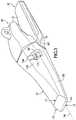
- FIG. 1is a perspective view of a wear assembly in accordance with the present invention.
- FIG. 2is a side view of the wear assembly.
- FIG. 3is a cross-sectional view of the wear assembly vertically taken along the longitudinal axis.
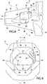
- FIG. 4is an upper perspective view of a base of the wear assembly.
- FIG. 5is a lower perspective view of the nose of the base.
- FIG. 6is a top view of the nose.
- FIG. 7is a side view of the base.
- FIG. 8is a side view of the nose.
- FIG. 9is a front view of the base.
- FIG. 10is a cross-sectional view of the base taken along such section line 10 - 10 in FIG. 9 .
- FIG. 11is a cross-sectional view of the base taken along such section line 11 - 11 in FIG. 8 .
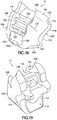
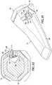
- FIG. 12is a perspective view of a wear member of the wear assembly.
- FIG. 13is an enlarged view of the part of the wear member within the circle c in FIG. 12 .
- FIG. 14is a rear view of the wear member.
- FIG. 15is a side view of the wear member.
- FIG. 16is a cross-sectional view taken along section line 16 - 16 in FIG. 14 .
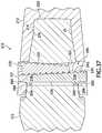
- FIG. 17is a cross-sectional view taken along section line 17 - 17 in FIG. 14 .
- FIGS. 18 and 19are each a perspective view of a lock for the wear assembly.
- FIG. 20is a front view of the lock.
- FIG. 21is a side view of the lock.
- FIG. 22is a cross-sectional view taken along line 22 - 22 in FIG. 21 .
- FIGS. 23-25are transverse cross-section views showing the incremental installation of the lock into the wear assembly with a pry tool.
- FIGS. 26-29are transverse cross-sectional views showing the incremental removal of the lock from the wear assembly with a pry tool.
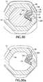
- FIG. 30is an enlarged, transverse cross-sectional view of the wear assembly with the lock in the hold position in the assembly.
- FIG. 30 ais an enlarged, transverse cross-sectional view of the wear member combined with the lock in the hold position.
- FIG. 31is a perspective view of the wear member with the lock in the release position.
- FIG. 32is an enlarged transverse cross-sectional view of the lock in the release position.
- FIG. 33is a perspective view of a second embodiment of a wear assembly in accordance with the present invention.
- FIG. 34is an exploded perspective view of the second embodiment.
- FIG. 35is a side view of the nose of the second embodiment.
- FIG. 36is a rear view of the wear member of the second embodiment.
- FIG. 37is a partial cross-sectional view taken vertically along the longitudinal axis.
- the present inventionpertains to a wear assembly 10 for releasably attaching a wear member 12 to excavating equipment (not shown).
- wear member 12is described in terms of a point for an excavating tooth that is attached to a lip of an excavating bucket.
- the wear membercould be in the form of other kinds of wear parts (e.g., shrouds) or attached to other excavating equipment (e.g., dredge cutterheads).
- relative termssuch as forward, rearward, up, down, horizontal or vertical are used for convenience of explanation with reference to the orientation of the assembly in FIG. 1 ; other orientations are possible.
- the wear member or point 12is adapted to fit on a nose 14 .
- the noseis the front portion of a base 15 that is fixed to a bucket (not shown) or other equipment.
- the rear mounting portion 19 of base 15can be fixed to the bucket in a number of common ways.
- base 15includes a pair of rearward legs 21 ( FIGS. 1-3 ) that extend over and are welded to the lip of a bucket. Nevertheless, the base can include only one leg, be cast as part of the lip, or be mechanically fixed to the bucket lip, such as by a Whisler-style lock.
- the baseis typically called an adapter.
- the basecan also consist of a plurality of interconnected adapters. Wear member 12 is releasably secured to nose 14 by a lock 17 .
- Nose 14includes a body 18 and a front end 20 ( FIGS. 3-11 ).
- the front end 20preferably has a generally triangular shape with a horizontal lower surface 22 and a pair of inclined surfaces 24 facing upward and outward, collectively defining an inverted V-shape.
- the lower and upper surfaces 22 , 24are front stabilizing surfaces that are substantially parallel to the longitudinal axis 26 of the nose.
- the term “substantially parallel”is intended to include parallel surfaces as well as surfaces that diverge rearwardly from axis 26 at a small angle (e.g., of about 1-7 degrees) for manufacturing or other purposes. A small divergence may also ease removal of the wear member from the nose.
- each stabilizing surface 22 , 24diverges rearwardly at an angle of no more than about 5 degrees and most preferably about 2-3 degrees to axis 26 .
- Loads that shift between vertical and side loadsare also better resisted by the same upper surfaces 24 to reduce shifting of wear member 12 on nose 14 , and thereby reduce wearing of the components.
- the larger surface area provided by both angled upper surfaces 24 as compared to lower surface 22can also provide a benefit in resisting the expected larger downward loads.
- upper surfaces 24are preferably more horizontal than vertical, i.e., at an angle ⁇ between 0 and 45 degrees relative to lower surface 22 , and most preferably at an angle ⁇ of about 40 degrees ( FIG. 9 ). Nevertheless, inclinations outside the preferred range are possible, particularly in light duty operations or in environments where high side loading can occur. Lower surface 22 is provided to resist upward vertical loading.
- a triangularly-shaped front end(along with other parts of the nose) also ensures that wear member 12 will be mounted properly on the nose, i.e., the wear member cannot be mounted the wrong way on the nose.
- the nose and socketcan be formed to optimize shape for a given application.
- the nosemay be formed with a profile for greater penetration, a shape that reduces the rate of wear on the wear member, and an efficient construction to specially suit loads and wear patterns expected in the desired digging operations.
- This reduced profile at its lateral endsreduces the wearing and stress on the upper lateral ends of the socket and nose compared to conventional teeth. As a result, the usable lives of the wear member and the nose are increased.
- the triangular front end 20 of nose 14defines a smaller profile for better penetration into the ground. The use of inclined surfaces at the upper corners allows the wear member to be shaped such that more surface area is available to carry earthen materials into the bucket.
- front stabilizing end 20preferably has a triangular shape formed by upper and lower surfaces 22 , 24
- other configurations with inclined side surfacescan be used to reduce the lateral projection of the upper front corners.
- the inclined sidewallsmay define a generally trapezoidal shape.
- the upper cornersmay be chamfered to shift the upper corners inward. The chamfers may be made so as to eliminate the sidewalls and/or top walls or to connect the side and top walls.
- planar surfacesare preferred, the inclined surfaces may be curved to define, for example, a generally hemispherically shaped front end.
- a triangular shaped front end 20 or other front end shapes with inclined sidewallscould be used in connection with other known nose configurations.
- a front endcould be used as a stabilizing front end instead of the stabilizing front end disclosed on the nose in U.S. Pat. No. 5,709,043.
- the front endcould be reversed for digging operations where the loads and wear would be expected to be along the bottom side as opposed to the top side of the wear assembly.
- Nose 14is further defined in part by an upper wall 31 and a lower wall 33 ( FIGS. 3 and 10 ).
- Upper and lower walls 31 , 33converge toward front thrust surface 27 to form the common wedge shape to provide a compromise of strength and the ability to penetrate.
- the central portion 34 of upper wall 31continues to converge toward lower wall 33 through front end 20 to the thrust surface 27 for a slimmer outer profile and enhanced penetration without sacrificing stability. This continued tapering of upper wall 31 through front end 20 and the accompanying slimming of the nose is possible because of the use of the inclined stabilizing surfaces 24 to provide the stabilizing support.
- upper wall 31 and a lower wall 33that are each inclined to diverge away from axis 26 in a rearward direction.
- upper wall 31has a more shallow inclination relative to axis 26 than lower wall 33 .
- nose 14transitions rearwardly from a relatively small sized front end 20 with facets 22 , 24 for high penetration and stability into a larger sized rear end with increased facets for strength and support ( FIGS. 3-11 ).
- the nosechanges from a generally triangular front end into a six-faceted body, which in turn transitions into an eight-faceted body at its rear end.
- nose 14transitions from a three or four-faceted surface at the front end (depending on whether central facet 34 maintains a significant width in front end 20 ) into a six-faceted surface into body 18 for strength, stability and a slimmer profile.
- Body 18preferably comprises an upper central facet 34 and a pair of inclined side facets 36 , and a lower central facet 38 and inclined side facets 40 to present a strong profile.
- the use of central facets 34 , 38reduces the overall depth of the assembly to provide a more slender projection for better penetration.
- the top central facet 34is preferably flat in a transverse direction with a width that expands rearwardly to ease the flow of earthen material into the bucket.
- the lower central facet 38is also generally flat in a transverse direction, but preferably has a narrowing width in a rearward direction. This is particularly beneficial on account of the greater inclination of lower side 33 as compared to upper side 31 . While planar facets 34 , 36 , 38 , 40 are preferred, curved facets could also be used. Nevertheless, other shapes and arrangements where the nose changes from a relatively small sized front end with a certain facets into a larger sized rear end with increased facets are possible.
- Lower side facets 40are preferably substantially parallel to axis 26 to define rear stabilizing surfaces ( FIGS. 5, 7, 8 and 9 ). As with front stabilizing surfaces 24 , rear stabilizing surfaces 40 are laterally inclined to resist both vertical and side loading. The inclination of stabilizing surfaces 40 should be chosen as a balance between stabilizing the wear member under vertical loading and providing the assembly with sufficient overall strength. Accordingly, side facets 40 are preferably inclined relative to central facet 38 at an angle ⁇ between 105 and 180 degrees, and most preferably at an angle of about 128 degrees ( FIG. 11 ). Nevertheless, stabilizing surfaces 40 could be inclined outside of the preferred range, particularly in light duty operations or those involving high side loading. The rearward narrowing of central facet 38 also maximizes the rearward expansion of stabilizing surfaces 40 to provide greater surface area for resisting loads, particularly at the rear of nose 14 .
- body 25transitions into an eight-faceted structure at its rear end 41 ( FIGS. 4, 5, 7 and 8 ).
- nose 14further includes a pair of opposite, vertically positioned side surfaces 43 to reduce the profile of the nose for better penetration and to provide additional support to resist side loads.
- the use of a nose and socket which transitions through three phases, each having more facets than the more forward phases (excluding surfaces pertaining to the lock or those of ridges and grooves),provides an advantageous combination of strength and slenderness for improved operation and penetration.
- the first front phaseincludes four facets
- the middle phase rearward of the front stabilizing endincludes six facets
- the rear phasedefines eight facets rearward of the lock (though it could extend forward of the lock if desired).
- facet 34does not extend through the front end 20 , then the first phase would have three facets. In either case, the front end 20 is considered to be generally triangular.
- Base 15further includes supports 42 adjacent nose 14 for additional stabilization of wear member 12 under upwardly directed loads ( FIGS. 4-9 ).
- supports 42are substantially parallel to axis 26 and oriented generally in a horizontal orientation, though they could be laterally inclined to resist both vertical and side loads.
- One support 42sets to each side of nose 14 just below the intersection of facets 36 , 40 , although they could be at or just above the intersection.
- upper stabilizing surfaces 42are laterally offset from lower stabilizing surfaces 40 . This offset, juxtaposed relationship of the lower and upper stabilizing surfaces 40 , 42 on base 15 enables the use of a more slender tooth system than if upper facets 36 were designed to be stabilizing surfaces that, for example, mirror lower facets 40 .
- supports 42provide stabilization against upward loads
- upper facets 36are inclined in both axial and lateral directions, without defining stabilization surfaces substantially parallel to axis 26 .
- side facets 36avoid extending farther upward and impeding the flow of earthen material into the bucket.
- facets 36could be formed as stabilizing surfaces with or without supports 42 , or other arrangements of stabilizing surfaces could be used.
- supports 42are preferably structured to resist only vertical loading, a single support on one side could be provided if desired.
- Wear member 12includes a bit 28 with a front digging edge 44 and a mounting end 46 with a rearwardly-opening socket 16 ( FIGS. 1-3 and 12-17 ).
- Socket 16is preferably formed to matingly receive nose 14 , although differences between the nose and socket could exist. Accordingly, socket 16 preferably includes a generally triangular-shaped stabilizing front end 48 having a lower stabilizing surface 52 and a pair of upper stabilizing surfaces 54 ( FIG. 14 ). Stabilizing surfaces 52 , 54 are substantially parallel to axis 26 . As with nose 14 , socket 16 transitions into a larger main portion 56 defined by an upper side 58 and a lower side 60 .
- Upper side 58includes a top facet 64 and side facets 66 to correspond to facets 34 , 36 on nose 14 .
- lower side 60includes a bottom facet 68 and side facets 70 to correspond to facets 38 , 40 on nose 14 .
- Side facets 70are also substantially parallel to longitudinal axis 26 to bear against side facets 40 under certain loads.
- Side surfaces 71are also provided to bear against side surfaces 43 .
- Mounting end 46further includes shoulders 72 formed by an offset portion 74 of upper side 58 that overhangs past the rear end of lower side 60 ( FIGS. 1, 2, 12 and 14-17 ).
- Shoulders 72are substantially parallel to axis 26 and oriented generally horizontal to bear against supports 42 .
- Shoulders 72are integral with upper side 58 rather than extending rearwardly like known cantilevered ears. This arrangement, then, as compared to cantilevered ears, provides shoulders 72 with greater support and requires the use of less metal. Nevertheless, it is possible to provide ears to bear against supports 42 .
- stabilizing surfaces 22 , 24 , 40 , 42 , 52 , 54 , 70 , 72are intended to be the primary surfaces for resisting vertical and side loads that are applied to the wear member.
- the wear memberis urged to roll forward off the nose.
- a downward load L 1is applied to the top of digging edge 44 ( FIG. 1 )
- wear member 12is urged to roll forward on nose 14 such that front stabilizing surfaces 54 in socket 16 bear against stabilizing surfaces 24 at the front end of nose 14 .
- the rear end 79 of lower side 60 of wear member 12is also drawn upward against the lower side 33 of nose 14 such that rear stabilizing surfaces 70 in socket 16 bear against stabilizing surfaces 40 of nose 14 .
- stabilizing surfaces 40 , 70provides more stable support for the point as compared to the use of conventional converging surfaces, with less reliance on the lock. For instance, if load L 1 is applied to a tooth with a nose and socket defined by converging top and bottom walls without stabilizing surfaces 40 , 70 , the urge to roll the wear member off the nose is resisted in part by the abutting of converging walls at the rear ends of the nose and socket. Since these converging walls are axially inclined to the longitudinal axis, their abutment with each other urges the point in a forward direction, which must be resisted by the lock. Accordingly, in such known constructions, a larger lock is needed to hold the point to the nose.
- a larger lockrequires larger openings in the nose and point, thus, reducing the overall strength of the assembly.
- stabilizing surfaces 40 , 70(in conjunction with stabilizing surfaces 24 , 54 ) are substantially parallel to longitudinal axis 26 to minimize forward urging of wear member 12 .
- the wear memberis stably supported on the nose to increase the strength and stability of the assembly, reduce wear, and enable the use of smaller locks.
- Stabilizing surfaces 22 , 42 , 52 , 72function in essentially the same manner for upwardly-directed vertical loads.
- An upwardly directed load L 2( FIG. 1 ) causes front stabilizing surface 52 of socket 16 to bear against stabilizing surface 22 on the front end of nose 14 .
- the upward rolling of wear member 12 on nose 14is also resisted by shoulders 72 bearing against supports 42 at the rear ends of wear member 12 and nose 14 .
- These stabilizing surfaces 22 , 42 , 52 , 72can have a smaller surface than stabilizing surfaces 40 , 70 because the bulk of the loads are expected to be rearward and downward.
- stabilizing surfaces 24 , 40 , 54 , 70are inclined in transverse directions. Preferably, these angled stabilizing surfaces are symmetrical, although an asymmetrical arrangement is possible.
- the transverse inclination of stabilizing surfaces 24 , 40 , 54 , 70enables them to resist side loads, such as load L 3 ( FIG. 1 ).
- side loadssuch as load L 3 ( FIG. 1 ).
- the application of side load L 3causes wear member 12 to laterally cant on nose 14 .
- the front stabilizing surface 54 on the side L 3is applied is pushed laterally inward to bear against front stabilizing surface 24 on nose 14 .
- the rear portion 79 of facet 70 on the opposite sidewall of socket 16is drawn inward to bear against the corresponding facet 40 .
- the opposite stabilizing surfaces 24 , 54 , 40 , 70work in the same way for oppositely directed side loads.
- Stabilizing surfaces 22 , 42 , 52 , 72are not inclined in the preferred embodiment because the bulk of the loads are expected to be rearward and downward, and the use of horizontal stabilizing surfaces in this direction enables the design of an assembly with less depth.
- Stabilizing surfaces 22 , 24 , 40 , 42 , 52 , 54 , 70 , 72are preferably planar, but could have different shapes.
- the stabilizing surfacescould be formed with broad convex or concave curves.
- rear stabilizing surfaces 40 , 70are generally most effective when located at or near the rear end of the nose and socket.
- the front portions of stabilizing surfaces 40 , 70taper to a front point.
- the front portionscould have other narrowing shapes, non-converging shapes, or be eliminated entirely. Further, bearing may occur on only one portion of any or all of the stabilizing surfaces.
- lock 17fits into an opening in the form of through-hole 81 defined in wear member 12 and a pocket or cavity 83 defined in one side of nose 14 ( FIGS. 1-2 ).
- Lock 17is movable between a hold position ( FIGS. 1, 2 and 30 ) where the lock 17 holds wear member 12 to nose 14 , and a release position ( FIGS. 31 and 32 ) where wear member 12 can be installed on or removed from nose 14 .
- Through-hole 81preferably extends through a side facet 66 ( FIGS. 1, 2 and 12-16 ), but could be formed in other parts of the wear member.
- Through-hole 81has a generally rectangular shape with two end walls 85 , 87 , front wall 89 and rear wall 91 , but could have other shapes.
- One end wall 85defines a pivot member 93 in the form of a rounded bulb ( FIG. 16 ).
- the bulb 93is preferably turned inward, toward nose 14 , to alleviate the risk of wearing the bulb away.
- Bulb 93defines an axis that extends generally in a longitudinal direction relative to the wear assembly and is structured such that loading is minimized during use.
- Rear wall 91preferably includes an expanded portion 91 a that extends into socket 16 to provide a larger bearing face for the lock and to move the bearing moment inward to reduce the tendency of the wear member 12 to cant on base 15 due to the lock securing only one side.
- Nose 14includes recess 94 to accommodate the presence of the inward extension of rear wall 91 .
- Lock 17( FIGS. 18-22 ) includes a narrow end 103 , a wide end 105 , a front face 107 , and a rear face 109 , though other shapes are possible.
- Narrow end 103is formed as a pivot member 113 , which preferably defines an arcuate recess to cooperate with bulb 93 on end wall 85 to enable the lock to pivotally swing between hold and release positions.
- Pivot members 93 , 113could be reversed so that the bulb is formed on lock 17 and the recess on wear member 12 , or have a different construction that defines the pivot axis.
- Wide end 105includes a latch formation 115 that cooperates with end wall 87 to retain lock 17 in hold and release positions.
- pivot member 93could be formed on end wall 87 and the latch formation 115 adapted to engage end wall 85 , they are preferably as illustrated to minimize obstructions with adjacent wear assemblies during installation or release.
- lock 17is composed of a body 110 , a resilient member 112 and a shield 114 all bonded or otherwise secured together.
- Body 110defines latch formation 115 that engages end wall 87 and stop 95 .
- Shield 114overlies resilient member 112 to engage bulb 93 .
- Resilient member 112provides lock 17 with a resilient compressibility.
- Cavity 83 in nose 14is preferably defined by base walls 129 , 131 collectively having a generally L-shaped configuration, a front wall 133 , and a rear wall 135 ( FIGS. 4, 6, 7 and 8 ). Since cavity 83 does not extend through nose 14 , it retains more of the nose strength.
- Base wall 129provides a platform against which lock 17 can set to prevent excessive insertion.
- Base wall 131is preferably curved to follow the arcuate path of lock 17 when swung into the hold position.
- Lock 17fits into through-hole 81 such that pivot member 113 bears against bulb 93 for pivotal movement of the lock between the hold position and the release position ( FIGS. 23-32 ).
- lock 17is swung about bulb 93 to fit fully within cavity 83 .
- a tool Tis used to move the lock into the hold position; i.e., tool T is placed into a slot 132 ( FIGS. 12 and 13 ) in bulb 93 and used to pry lock 17 into the hold position ( FIGS. 23-25 ).
- the toolis able to force fingers 116 past end wall 87 adjacent stop 95 with the compression of resilient member 112 .
- fingers 116opposes facet 66 in socket 16 to prevent movement of lock 17 away from the hold position.
- end wall 87operates as catch for lock 17 .
- a separate structure to operate as a catchcould be used but is not necessary.
- lock 17preferably has two spaced apart fingers 116 , a single finger 116 could be used.
- a recess 134is preferably provided in outer surface 125 of wear member 12 to accommodate the desired movement of tool T. However, other prying arrangements could be used.
- latch formation 115includes fingers 116 that set behind facet 66 to prevent release of the lock from the assembly; resilient member 112 biases finger 116 behind facet 66 after insertion of lock 17 (although lock 17 is preferably not tight against end wall 87 ).
- the outer face 123 of lock 17is generally aligned with or slightly recessed relative to the outer surface 125 of wear member 12 ( FIG. 30 ). In this way, the lock is partially protected from wearing and forms no obstruction to the flow of earthen material into the bucket.
- Lock 17further includes a recess 120 along wide end 105 .
- Notch 120receives stop 95 to hold lock 17 in its release position ( FIGS. 23, 31 and 32 ); resilient member 112 releasably holds the lock in this position.
- a protrusion 120 apreferably extends outward at the distal end of recess 120 to prevent lock 17 from moving out of through-hole 81 .
- lock 17never needs to be removed from through-hole 81 in wear member 12 .
- Lock 17is installed into wear member 12 (in the release position) at the time of manufacture and shipped to a customer ( FIG. 30 a ). The customer stores the wear member with the lock in it until needed for use.
- a depression 130is preferably provided in nose 14 to accommodate passage of lock 17 in its release position during installation of the combined wear member and lock ( FIGS. 4 and 7 ).
- a relief 130 ais also preferable provided to permit passage of bulb 93 during installation of point. Then, the lock is swung to its hold position to secure wear member 12 to base 15 ( FIG. 30 ).
- This arrangementreduces shipping and storage costs, virtually eliminates losing the locks in storage or at the installation site in the field, and eases the installation process. Nevertheless, lock 17 could be completely removed from wear member 12 if desired for shipping, storage, replacement, installation and/or removal.
- lock 17is placed in the hold position to secure wear member 12 to base 15 .
- Lock 17is preferably shipped and/or stored in combination with wear member 12 in the release position without base 15 .
- Lock 17could be structured to store and/or ship in the hold position or some rearward position if desired.
- Lock 17preferably includes abutments 128 that prevent lock 17 from falling through through-hole 81 and into socket 16 when nose 14 is absent.
- Lock 17further includes notches 122 , 124 , 126 which are provided to aid removal of lock 17 from the assembly ( FIGS. 18 and 22 ).
- a tool Tis used to engage notches 122 , 124 , 126 ( FIGS. 26-29 ) as needed to pivot lock 17 from the hold position to the release position.
- the toolis initially placed in notch 126 ( FIG. 26 ) and moved using stop 95 as a fulcrum to bias lock 17 toward bulb 93 against the bias of resilient member 112 ( FIG. 27 ) and to swing lock 17 outward such that fingers 116 swing past end wall 87 and set outside of the through-hole 81 ( FIG. 28 ).
- tool Tis placed successively within notches 124 and 122 to swing lock 17 to the release position.
- the successive notchesare for better leverage and ease of use.
- front and rear faces 107 , 109 of lock 17are generally parallel to the opposed front and rear walls 133 , 135 of pocket 83 . In this way, a firm engagement can be had between the lock and the pocket. Nevertheless, in an alternative construction, faces 107 and 109 of lock 17 converge toward inner side 149 to engage similarly converging walls 133 , 135 of pocket 83 . In this way, the lock can be more easily inserted and removed from pocket 83 as the walls do not engage until fully positioned.
- wear assembly 210is shown as a tooth for a ripper machine ( FIGS. 33-37 ).
- the wear assemblyincludes a wear member 212 in the form of a point, a base 215 adapted to be fixed to a ripper arm, and a lock 217 to secure wear member 212 to base 215 .
- Base 215includes a nose 214 which is received in socket 216 in wear member 212 .
- the configurations of nose 214 and socket 216are generally the same as nose 14 and socket 16 discussed above in regard to wear assembly 10 . Nevertheless, there can be some changes, as illustrated, such as the omission of the formations related to the locking arrangement and the omission of side surfaces 43 , 71 .
- Nose 214 and socket 216each includes a generally triangular front end 220 , which transitions rearwardly into a six-faceted structure. In the illustrated example, the nose and socket do not later transition into an eight-faceted structure as in wear assembly 10 (though it could if desired).
- lock 217includes a wedge 230 and a spool 231 such as disclosed in U.S. Pat. No. 7,174,661, herein incorporated by reference.
- Wedge 230has a conical shape and a thread formation in the form of a helical groove 234 ( FIGS. 34 and 37 ).
- Spool 231includes a pair of arms 236 and a body 238 interconnecting the arms.
- Body 238defines a trough 240 in which is received wedge 230 .
- Trough 240includes spaced helical ridges 242 for receipt within groove 234 . In this way, wedge 230 is threaded to spool 231 so that it can be drawn into the assembly by turning the wedge with a wrench or other tool.
- Hole 283extends horizontally through a mid-section of nose 214 to receive lock 217 ( FIG. 33 ), but could extend vertically or diagonally.
- Wear member 212defines a pair of through-holes 281 which generally align with hole 283 when nose 214 is fully received into socket 216 ( FIGS. 33-37 ).
- Through-holes 281 and hole 283collectively define an opening 285 to receive lock 217 .
- Arms 236abut against the rear ends 290 of through-holes 281 while wedge 230 bears against the front wall 292 of hole 283 .
- Arms 236each preferably includes a lip 294 to set within a relief 296 defined in wear member 212 to prevent inadvertent ejection of lock 217 during use ( FIG. 37 ).
- lock 17could be reversed such that the spool (without arms) engaged front wall 292 and the wedge engaged rear ends 290 .
- wear member 212is placed over nose 214 so that through-holes 281 generally align with hole 283 to collectively define opening 285 .
- Lock 217is placed into opening 285 with the arms 236 abutting against rear ends 290 of through-holes 281 and wedge 230 being loosely received into trough 240 .
- Wedge 230is rotated such that the receipt of ridges 242 in helical groove 234 pulls the wedge farther into opening 285 until the lock has firmly secured wear member 212 to base 215 .
Landscapes
- Engineering & Computer Science (AREA)
- Mining & Mineral Resources (AREA)
- Civil Engineering (AREA)
- General Engineering & Computer Science (AREA)
- Structural Engineering (AREA)
- Mechanical Engineering (AREA)
- Component Parts Of Construction Machinery (AREA)
- Earth Drilling (AREA)
- Socks And Pantyhose (AREA)
Abstract
Description
Claims (35)
Priority Applications (1)
| Application Number | Priority Date | Filing Date | Title |
|---|---|---|---|
| US15/809,793US10829912B2 (en) | 2006-03-30 | 2017-11-10 | Wear assembly for use on earth working equipment |
Applications Claiming Priority (8)
| Application Number | Priority Date | Filing Date | Title |
|---|---|---|---|
| US78726806P | 2006-03-30 | 2006-03-30 | |
| US11/729,502US7882649B2 (en) | 2006-03-30 | 2007-03-28 | Wear assembly |
| US13/005,791US8122621B2 (en) | 2006-03-30 | 2011-01-13 | Wear assembly |
| US13/369,699US20120137493A1 (en) | 2006-03-30 | 2012-02-09 | Method Of Shipping A Wear Assembly |
| US13/705,691US8689472B2 (en) | 2006-03-30 | 2012-12-05 | Wear assembly |
| US14/213,538US9493930B2 (en) | 2006-03-30 | 2014-03-14 | Lock for securing a wear assembly to excavating equipment |
| US14/640,999US9816254B2 (en) | 2006-03-30 | 2015-03-06 | Wear assembly for use on earth working equipment |
| US15/809,793US10829912B2 (en) | 2006-03-30 | 2017-11-10 | Wear assembly for use on earth working equipment |
Related Parent Applications (1)
| Application Number | Title | Priority Date | Filing Date |
|---|---|---|---|
| US14/640,999DivisionUS9816254B2 (en) | 2006-03-30 | 2015-03-06 | Wear assembly for use on earth working equipment |
Publications (2)
| Publication Number | Publication Date |
|---|---|
| US20180087245A1 US20180087245A1 (en) | 2018-03-29 |
| US10829912B2true US10829912B2 (en) | 2020-11-10 |
Family
ID=38625459
Family Applications (13)
| Application Number | Title | Priority Date | Filing Date |
|---|---|---|---|
| US11/729,502Active2028-09-19US7882649B2 (en) | 2006-03-30 | 2007-03-28 | Wear assembly |
| US13/005,791ActiveUS8122621B2 (en) | 2006-03-30 | 2011-01-13 | Wear assembly |
| US13/369,699AbandonedUS20120137493A1 (en) | 2006-03-30 | 2012-02-09 | Method Of Shipping A Wear Assembly |
| US13/705,615ActiveUS8839535B2 (en) | 2006-03-30 | 2012-12-05 | Wear assembly |
| US13/705,562AbandonedUS20130091684A1 (en) | 2006-03-30 | 2012-12-05 | Method Of Shipping A Wear Assembly |
| US13/705,691ActiveUS8689472B2 (en) | 2006-03-30 | 2012-12-05 | Wear assembly |
| US14/213,538ActiveUS9493930B2 (en) | 2006-03-30 | 2014-03-14 | Lock for securing a wear assembly to excavating equipment |
| US14/641,046Expired - Fee RelatedUS9650764B2 (en) | 2006-03-30 | 2015-03-06 | Wear assembly for use on earth working equipment |
| US14/641,059AbandonedUS20150176258A1 (en) | 2006-03-30 | 2015-03-06 | Wear assembly for use on earth working equipment |
| US14/641,014AbandonedUS20150176256A1 (en) | 2006-03-30 | 2015-03-06 | A wear assembly for use on earth working equipment |
| US14/640,999ActiveUS9816254B2 (en) | 2006-03-30 | 2015-03-06 | Wear assembly for use on earth working equipment |
| US14/642,540AbandonedUS20150176259A1 (en) | 2006-03-30 | 2015-03-09 | Wear assembly for use on earth working equipment |
| US15/809,793Active2027-04-28US10829912B2 (en) | 2006-03-30 | 2017-11-10 | Wear assembly for use on earth working equipment |
Family Applications Before (12)
| Application Number | Title | Priority Date | Filing Date |
|---|---|---|---|
| US11/729,502Active2028-09-19US7882649B2 (en) | 2006-03-30 | 2007-03-28 | Wear assembly |
| US13/005,791ActiveUS8122621B2 (en) | 2006-03-30 | 2011-01-13 | Wear assembly |
| US13/369,699AbandonedUS20120137493A1 (en) | 2006-03-30 | 2012-02-09 | Method Of Shipping A Wear Assembly |
| US13/705,615ActiveUS8839535B2 (en) | 2006-03-30 | 2012-12-05 | Wear assembly |
| US13/705,562AbandonedUS20130091684A1 (en) | 2006-03-30 | 2012-12-05 | Method Of Shipping A Wear Assembly |
| US13/705,691ActiveUS8689472B2 (en) | 2006-03-30 | 2012-12-05 | Wear assembly |
| US14/213,538ActiveUS9493930B2 (en) | 2006-03-30 | 2014-03-14 | Lock for securing a wear assembly to excavating equipment |
| US14/641,046Expired - Fee RelatedUS9650764B2 (en) | 2006-03-30 | 2015-03-06 | Wear assembly for use on earth working equipment |
| US14/641,059AbandonedUS20150176258A1 (en) | 2006-03-30 | 2015-03-06 | Wear assembly for use on earth working equipment |
| US14/641,014AbandonedUS20150176256A1 (en) | 2006-03-30 | 2015-03-06 | A wear assembly for use on earth working equipment |
| US14/640,999ActiveUS9816254B2 (en) | 2006-03-30 | 2015-03-06 | Wear assembly for use on earth working equipment |
| US14/642,540AbandonedUS20150176259A1 (en) | 2006-03-30 | 2015-03-09 | Wear assembly for use on earth working equipment |
Country Status (31)
| Country | Link |
|---|---|
| US (13) | US7882649B2 (en) |
| EP (8) | EP3263776B1 (en) |
| JP (6) | JP5054758B2 (en) |
| KR (4) | KR101483416B1 (en) |
| CN (5) | CN104652524B (en) |
| AP (2) | AP2725A (en) |
| AR (5) | AR060242A1 (en) |
| AU (3) | AU2007241122C1 (en) |
| BR (6) | BRPI0709884B1 (en) |
| CA (3) | CA2644577C (en) |
| CL (1) | CL2014003218A1 (en) |
| CO (1) | CO5960134A1 (en) |
| CY (2) | CY1118142T1 (en) |
| DK (2) | DK1999317T3 (en) |
| EA (1) | EA013585B1 (en) |
| EG (2) | EG25073A (en) |
| ES (8) | ES2555177T3 (en) |
| HU (2) | HUE028386T2 (en) |
| JO (1) | JO3201B1 (en) |
| LT (1) | LT2902552T (en) |
| MX (3) | MX355372B (en) |
| MY (3) | MY183755A (en) |
| NZ (4) | NZ618917A (en) |
| PE (5) | PE20130952A1 (en) |
| PL (8) | PL3263776T3 (en) |
| PT (8) | PT2902552T (en) |
| SI (2) | SI2902552T1 (en) |
| TW (2) | TWI535918B (en) |
| UA (1) | UA96594C2 (en) |
| WO (1) | WO2007123653A2 (en) |
| ZA (1) | ZA200807180B (en) |
Families Citing this family (80)
| Publication number | Priority date | Publication date | Assignee | Title |
|---|---|---|---|---|
| JP2628826B2 (en) | 1993-01-29 | 1997-07-09 | 住友ゴム工業株式会社 | Band material sticking molding method in tire molding machine |
| AU2013202342B2 (en)* | 2006-02-17 | 2013-11-07 | Esco Corporation | Wear assembly |
| PL3263776T3 (en) | 2006-03-30 | 2022-01-17 | Esco Group Llc | Wear assembly |
| EP2246488B1 (en)* | 2006-08-16 | 2019-10-02 | Caterpillar Inc. | Ground engaging tool system |
| CN101558206B (en)* | 2006-09-01 | 2011-12-14 | 麦塔洛吉尼亚股份有限公司 | Prong and fitting for a dredging machine |
| US7526886B2 (en)* | 2006-10-24 | 2009-05-05 | Esco Corporation | Wear assembly for an excavating bucket |
| US8061064B2 (en) | 2007-05-10 | 2011-11-22 | Esco Corporation | Wear assembly for excavating equipment |
| PL2865814T3 (en)* | 2007-05-10 | 2019-05-31 | Esco Group Llc | Wear assembly for excavating equipment |
| CA2612341A1 (en)* | 2007-11-27 | 2009-05-27 | Black Cat Blades Ltd. | Ground engaging tool blade |
| EA022167B1 (en)* | 2008-01-08 | 2015-11-30 | Эско Корпорейшн | Tip for an earth working roll for earth-moving machine |
| CA2721781C (en)* | 2008-04-18 | 2013-12-03 | Cqms Pty Ltd | A lock assembly for an excavator wear member |
| US20090277050A1 (en)* | 2008-05-06 | 2009-11-12 | Esco Corporation | Wear Assembly For Excavating Equipment |
| WO2010089423A1 (en)* | 2009-02-06 | 2010-08-12 | Metalogenia, S.A. | Coupling system for use between a wear element and an adaptor for excavator machines and similar, and components thereof |
| MX344454B (en)* | 2009-03-23 | 2016-12-16 | Black Cat Blades Ltd | Fully stabilized excavator tooth attachment. |
| US9359744B2 (en)* | 2009-08-05 | 2016-06-07 | H&L Tooth Company | Multipiece wear assembly |
| BR112012011448B1 (en)* | 2009-10-30 | 2019-11-05 | Esco Corp | excavation equipment wear element and assembly |
| JO3763B1 (en)* | 2010-04-20 | 2021-01-31 | Esco Group Llc | Coupling assemblies with enhanced take up |
| AU2011200650B2 (en)* | 2011-02-16 | 2015-05-14 | Castpoints Pty Ltd | Direct drill point assembly |
| JOP20200019A1 (en) | 2011-07-14 | 2017-06-16 | Esco Group Llc | Wear assembly |
| US8890672B2 (en) | 2011-08-29 | 2014-11-18 | Harnischfeger Technologies, Inc. | Metal tooth detection and locating |
| US8943717B2 (en) | 2011-10-08 | 2015-02-03 | Caterpillar Inc. | Implement tooth assembly with tip and adapter |
| US9062436B2 (en) | 2011-10-07 | 2015-06-23 | Caterpillar Inc. | Implement tooth assembly with tip and adapter |
| US9057177B2 (en) | 2011-10-08 | 2015-06-16 | Caterpillar Inc. | Implement tooth assembly with tip and adapter |
| US8943716B2 (en) | 2011-10-10 | 2015-02-03 | Caterpillar Inc. | Implement tooth assembly with tip and adapter |
| RS62977B1 (en)* | 2011-11-23 | 2022-03-31 | Esco Group Llc | Lock for a securing a wear member to ground-engaging equipment |
| FR2983880B1 (en)* | 2011-12-08 | 2014-11-21 | Afe Metal | MECHANICAL SYSTEM COMPRISING A WEAR PIECE AND A SUPPORT, AND BUCKET COMPRISING AT LEAST ONE SUCH A MECHANICAL SYSTEM |
| EP2815035B1 (en)* | 2012-02-17 | 2018-12-12 | ESCO Group LLC | Wear assembly |
| US8819967B2 (en) | 2012-03-21 | 2014-09-02 | Hensley Industries, Inc. | Adapter stabilization structure for bucket lip |
| US9746129B2 (en) | 2012-09-28 | 2017-08-29 | Momentive Performance Materials Inc. | Puck wear detection |
| EA039491B1 (en)* | 2012-10-31 | 2022-02-02 | Эско Груп Ллк | Wear member for ground-engaging equipment and wear assembly with said member |
| USD696698S1 (en)* | 2012-12-11 | 2013-12-31 | H&L Tooth Company | Wedge key |
| AU347849S (en)* | 2013-02-12 | 2013-04-02 | Cqms Pty Ltd | An excavator lip |
| AU347850S (en) | 2013-02-12 | 2013-04-02 | Cqms Pty Ltd | An excavator wear member |
| AU2013204854B2 (en) | 2013-04-12 | 2016-04-21 | Bradken Resources Pty Limited | Excavation Tooth Assembly |
| EP2829664A1 (en)* | 2013-07-22 | 2015-01-28 | Metalogenia Research & Technologies S.L. | Male and female parts for a wear assembly of an earth-moving machine's bucket |
| AU2014262221C1 (en) | 2013-11-25 | 2021-06-10 | Esco Group Llc | Wear part monitoring |
| PE20161422A1 (en)* | 2014-04-28 | 2017-01-08 | Metalogenia Res And Tech S L | TOOTH AND ADAPTER TO ATTACH THE TOOTH TO A WORK MACHINE |
| US10214879B2 (en)* | 2014-04-28 | 2019-02-26 | Metalogenia Research & Technologies S.L. | Tooth and adaptor for attachment of the tooth to a working machine |
| AU2015308757B2 (en)* | 2014-08-29 | 2020-04-09 | Esco Group Llc | Hammerless pin assembly |
| CN104612203B (en)* | 2015-02-03 | 2017-07-28 | 大连裕工耐磨技术发展有限公司 | One kind has external Quench reinforcement high abrasion excavator bucket teeth |
| US9957696B2 (en) | 2015-04-17 | 2018-05-01 | Caterpillar Inc. | Tool retention system |
| US9970181B2 (en) | 2015-04-17 | 2018-05-15 | Caterpillar Inc. | Lip for machine bucket |
| US9951500B2 (en) | 2015-04-17 | 2018-04-24 | Caterpillar Inc. | Tool retention system |
| CN104846871A (en)* | 2015-05-05 | 2015-08-19 | 柳州金特新型耐磨材料股份有限公司 | Wear-resisting bucket tooth for loader |
| US9611625B2 (en) | 2015-05-22 | 2017-04-04 | Harnischfeger Technologies, Inc. | Industrial machine component detection and performance control |
| US9670648B2 (en) | 2015-08-10 | 2017-06-06 | Caterpillar Inc. | Replaceable tip systems for a tine |
| AU2016354542B2 (en) | 2015-11-12 | 2019-03-07 | Joy Global Surface Mining Inc | Methods and systems for detecting heavy machine wear |
| US10106960B2 (en)* | 2015-11-25 | 2018-10-23 | Caterpillar Inc. | Lock assembly for ground engaging tool |
| US9840829B2 (en)* | 2015-12-01 | 2017-12-12 | Srj, Inc. | Flex pin |
| DK3452664T3 (en)* | 2016-05-05 | 2022-02-07 | Esco Group Llc | WEAR PARTS FOR EARTH MACHINING EQUIPMENT |
| US10508418B2 (en) | 2016-05-13 | 2019-12-17 | Hensley Industries, Inc. | Stabilizing features in a wear member assembly |
| CN114277881B (en) | 2016-09-09 | 2023-11-17 | 久益环球地表采矿公司 | Ground engaging tool locking system |
| US20190376712A1 (en)* | 2016-09-12 | 2019-12-12 | Technomirai Co., Ltd. | Digital smart energy saving system, method, and program |
| USD840441S1 (en) | 2016-12-15 | 2019-02-12 | Caterpillar Inc. | Adapter for a ground engaging machine implement |
| US10494794B2 (en)* | 2017-06-14 | 2019-12-03 | Caterpillar Inc. | Edge protection system for an implement |
| US10538899B2 (en)* | 2017-06-14 | 2020-01-21 | Caterpillar Inc. | Edge shroud and method for removing edge shroud from an implement |
| USD832310S1 (en) | 2017-08-30 | 2018-10-30 | Caterpillar Inc. | Adapter for a ground engaging machine implement |
| US10745891B2 (en)* | 2018-02-27 | 2020-08-18 | Komatsu Ltd. | Tooth adapter and bucket |
| CN108385768B (en)* | 2018-03-15 | 2020-11-06 | 宁波吉威熔模铸造有限公司 | Excavator bucket tooth fixing tooth seat |
| JOP20200249A1 (en)* | 2018-03-30 | 2019-09-30 | Esco Group Llc | Wear member, edge and process of installation |
| US11732445B2 (en)* | 2018-04-13 | 2023-08-22 | Caterpillar Inc. | Retention system for attaching tool bits to a blade assembly |
| USD918965S1 (en) | 2018-06-19 | 2021-05-11 | Hensley Industries, Inc. | Ground engaging wear member |
| US11926997B2 (en) | 2018-11-09 | 2024-03-12 | Talon Engineering Sdn Bhd | Locking mechanism for a wear assembly |
| CN109518755A (en)* | 2018-11-30 | 2019-03-26 | 马鞍山金顺来工业设计有限公司 | A kind of excavator bucket teeth |
| WO2020178462A1 (en) | 2019-03-01 | 2020-09-10 | Metalogenia Research & Technologies, S.L. | System for the attachment of wear elements in earth-moving machinery |
| USD888785S1 (en) | 2019-03-07 | 2020-06-30 | Caterpillar Inc. | Adapter for a ground engaging machine implement |
| USD905765S1 (en) | 2019-03-07 | 2020-12-22 | Caterpillar Inc. | Adapter for a ground engaging machine implement |
| US11492784B2 (en) | 2019-04-15 | 2022-11-08 | Hensley Industries, Inc. | Position-biased locking pin assembly for a ground engaging wear member |
| JP7160777B2 (en)* | 2019-09-13 | 2022-10-25 | 株式会社小松製作所 | Bucket tooth mounting structure and bucket tooth |
| US11634892B2 (en) | 2019-11-27 | 2023-04-25 | Hensley Industries, Inc. | Excavating tooth assembly with releasable lock pin assembly |
| CN111335377A (en)* | 2020-03-11 | 2020-06-26 | 袁军国 | Loader-digger for building site |
| WO2021246814A1 (en)* | 2020-06-05 | 2021-12-09 | 두산인프라코어 주식회사 | Tooth adapter |
| JP7450511B2 (en)* | 2020-10-07 | 2024-03-15 | 株式会社小松製作所 | Ripper point mounting structure and ripper point |
| USD945498S1 (en) | 2020-11-18 | 2022-03-08 | Caterpillar Inc. | Adapter for a ground engaging machine implement |
| USD945499S1 (en) | 2020-11-18 | 2022-03-08 | Caterpillar Inc. | Adapter for a ground engaging machine implement |
| CN112538875A (en)* | 2020-11-24 | 2021-03-23 | 李红恩 | Excavator bucket capable of quickly removing hard soil |
| BR112023017934A2 (en)* | 2021-03-12 | 2023-12-05 | Esco Group Llc | WEAR ASSEMBLY |
| RU206501U1 (en)* | 2021-04-28 | 2021-09-14 | Федеральное государственное бюджетное образовательное учреждение высшего образования "Брянский государственный аграрный университет" | TWO-STORY SOIL CUTTER |
| US20230323641A1 (en)* | 2022-04-11 | 2023-10-12 | Hensley Industries, Inc. | Excavating assembly system with collared fastening system |
| WO2025136617A1 (en)* | 2023-12-22 | 2025-06-26 | Esco Group Llc | Lock, wear member and wear assembly having a lock |
Citations (145)
| Publication number | Priority date | Publication date | Assignee | Title |
|---|---|---|---|---|
| US915809A (en) | 1908-10-30 | 1909-03-23 | Valentine C Thomas | Dipper-tooth. |
| US1375638A (en) | 1920-05-03 | 1921-04-19 | Jeffrey Mfg Co | Cutting-chain |
| US1834391A (en) | 1930-01-29 | 1931-12-01 | Bonney Floyd Co | Replaceable excavator tooth |
| US2305653A (en) | 1941-03-14 | 1942-12-22 | Abraham W Ward | Excavator tooth |
| US2397521A (en) | 1944-09-01 | 1946-04-02 | Cleveland Trencher Co | Rooter for excavators |
| US2450044A (en) | 1946-07-01 | 1948-09-28 | Bryan J Hobbs | Tool handle lock |
| US2490532A (en) | 1944-02-09 | 1949-12-06 | Jr Glenway Maxon | Dump truck |
| GB678382A (en) | 1949-08-27 | 1952-09-03 | Frank Wade Ltd | Improvements in or relating to ploughshares |
| US2688475A (en) | 1949-10-24 | 1954-09-07 | Everett T Small | Internal lock pin for scarifier teeth |
| US2807105A (en) | 1954-01-04 | 1957-09-24 | Tooth H & L Co | Detachable retaining means for digging teeth |
| US2870552A (en) | 1955-11-04 | 1959-01-27 | Forrest W Richardson | Two-piece digging tooth |
| US2885801A (en) | 1956-03-06 | 1959-05-12 | Electric Steel Foundry Co | Tooth structure for trenchers and the like |
| US3079710A (en) | 1961-06-22 | 1963-03-05 | Esco Corp | Ground-working tooth and method |
| US3117386A (en) | 1961-03-07 | 1964-01-14 | Ferwerda Ray | Tooth arrangement for earth digging apparatus |
| US3175314A (en) | 1959-08-03 | 1965-03-30 | Caterpillar Tractor Co | Retaining pin for telescoped parts comprising separate longitudinally bowed sequentially insertable resilient members |
| US3196956A (en) | 1962-12-21 | 1965-07-27 | American Brake Shoe Co | Digger tooth |
| US3197894A (en) | 1962-07-26 | 1965-08-03 | American Brake Shoe Co | Digging tooth with screws set into resilient pockets |
| US3225467A (en) | 1963-07-15 | 1965-12-28 | Petersen Gerald A | Tooth for digging equipment used in compacted soil |
| US3292281A (en) | 1964-01-17 | 1966-12-20 | Petersen Anita E | Reversible tooth with snap-on holding means |
| US3330601A (en) | 1963-07-08 | 1967-07-11 | Austin Hoy & Co Ltd | Cutter tools and tool-boxes therefor |
| US3334431A (en) | 1964-06-16 | 1967-08-08 | Dwight M Phillips | Digger tooth construction |
| US3397012A (en) | 1966-12-19 | 1968-08-13 | Cincinnati Mine Machinery Co | Cutter bits and means for mounting them |
| US3453756A (en) | 1968-03-13 | 1969-07-08 | Smith International | Reversible excavating tooth |
| US3469332A (en) | 1967-09-28 | 1969-09-30 | Earl W Leffingwell | Retaining means for excavating teeth |
| FR2032575A5 (en) | 1969-10-28 | 1970-11-27 | Villechenon Louis | |
| GB1215839A (en) | 1967-05-08 | 1970-12-16 | Deloro Ugine Carbone | Device for mounting a removable tip on a tip carrier and a tip carrier assembly including such a device |
| DE2052149A1 (en) | 1969-10-25 | 1971-11-11 | Kopalnia Wegla Brunatnego Adamow, Turek (Polen) | Excavator fang |
| US3624827A (en) | 1968-12-11 | 1971-11-30 | Caterpillar Tractor Co | Earthworking tooth and supporting adapter |
| FR2082069A6 (en) | 1970-03-02 | 1971-12-10 | Guibbert Jean | |
| GB1263030A (en) | 1970-06-15 | 1972-02-09 | Louis Villechenon | Tooth-holder assembly |
| US3675350A (en) | 1970-04-13 | 1972-07-11 | Amsted Ind Inc | Dipper tooth assembly |
| CA907661A (en) | 1969-11-19 | 1972-08-15 | Western Rock Bit Company Limited | Digger tooth retainer |
| US3760654A (en) | 1972-01-17 | 1973-09-25 | Pennsylvania Engineering Corp | Metallurgical vessel drive |
| US3767266A (en) | 1970-08-10 | 1973-10-23 | Cincinnati Mine Machinery Co | Resilient retaining means for connecting work tools and work tool holders |
| US3865437A (en) | 1973-08-16 | 1975-02-11 | Kennametal Inc | Rotary mining tool retaining structure |
| US3864854A (en) | 1973-10-01 | 1975-02-11 | Clifford J Evans | Digging tooth locking device |
| GB1410814A (en) | 1971-11-27 | 1975-10-22 | Caballero A | Means for securing the teeth of mechanical excavating implements |
| FR2298650A1 (en) | 1975-01-22 | 1976-08-20 | Mantovanibenne Spa | Tooth holder device for bucket of earth moving machine - has coupling extension fitting into cut out section |
| US4067657A (en) | 1976-02-17 | 1978-01-10 | Caterpillar Tractor Co. | Cam lock retaining means for ripper tips |
| JPS53137501A (en) | 1977-02-18 | 1978-12-01 | Esco Corp | Tooth member for excavation |
| JPS5513265U (en) | 1978-07-13 | 1980-01-28 | ||
| US4210374A (en) | 1978-03-03 | 1980-07-01 | Atlas Technologies Inc. | Set-screw bushing including integral electrical clamp |
| US4231173A (en) | 1977-02-18 | 1980-11-04 | Esco Corporation | Excavating tooth |
| US4320924A (en) | 1980-05-16 | 1982-03-23 | Elco International | Reciprocated concrete surfacer member with shielded spring return |
| US4367602A (en) | 1981-10-13 | 1983-01-11 | Petersen Gerald A | Lock and key retainer for excavator tooth |
| US4404760A (en) | 1980-04-28 | 1983-09-20 | Esco Corporation | Excavating tooth |
| GB2118616A (en) | 1982-03-22 | 1983-11-02 | Bofors Ab | Locking device for tools |
| GB2143801A (en) | 1983-07-26 | 1985-02-20 | Bofors Wear Parts Ab | Teeth for earth moving machines |
| US4501079A (en) | 1983-08-24 | 1985-02-26 | Esco Corporation | Two piece cutting edge construction |
| AU542726B2 (en) | 1982-03-10 | 1985-03-07 | Kennametal Inc. | Cutting tool assembly |
| US4505058A (en) | 1983-01-06 | 1985-03-19 | Peterson Gerald A | Excavating tooth, holder and retainer |
| US4599860A (en) | 1975-04-14 | 1986-07-15 | Automotive Products Plc | Liquid pressure apparatus |
| US4611418A (en) | 1985-03-28 | 1986-09-16 | Launder Richard L | Locking mechanism for earth excavation teeth |
| US4716666A (en) | 1986-09-29 | 1988-01-05 | Esco Corporation | Wear runner for excavating bucket |
| DE3720855C1 (en) | 1987-03-07 | 1988-02-25 | Hoesch Ag | Excavator tooth |
| US4747495A (en) | 1987-01-20 | 1988-05-31 | Chrysler Motors Corporation | Engine storage and transportation rack |
| US4748754A (en) | 1986-04-05 | 1988-06-07 | O&K Orenstein & Koppel Aktiengesellschaft | Shovel for an excavator |
| US4751785A (en) | 1984-11-20 | 1988-06-21 | Ab Bofors Wear Parts | Resilient retaining coil for excavator tooth |
| AU573942B2 (en) | 1984-12-24 | 1988-06-23 | Esco Corporation | Excavator tooth system |
| DE3720924A1 (en) | 1987-06-25 | 1989-01-12 | Hans Lederle | Endpiece of grab prong |
| US4831346A (en) | 1987-03-26 | 1989-05-16 | Andrew Corporation | Segmented coaxial transmission line |
| US4848013A (en) | 1988-10-24 | 1989-07-18 | Caterpillar Inc. | Two pin fastening assembly with interconnecting and retaining means |
| US4881331A (en) | 1985-04-03 | 1989-11-21 | Gamma Lock (Proprietary) Limited | Teeth for use with earth moving equipment |
| JPH0223062A (en) | 1988-07-08 | 1990-01-25 | Nec Corp | Switching power supply controlling circuit |
| US5009017A (en) | 1987-01-20 | 1991-04-23 | Caterpillar Inc. | Retaining pin having a positive keeper means |
| US5088214A (en) | 1991-01-17 | 1992-02-18 | Esco Corporation | Excavator wear edge |
| US5177886A (en) | 1992-03-16 | 1993-01-12 | Caterpillar Inc. | Tooth with clearances in socket |
| US5210965A (en) | 1990-01-23 | 1993-05-18 | Metal Parts, Inc. | Fabricated bucket tooth |
| US5241765A (en) | 1991-01-17 | 1993-09-07 | Esco Corporation | Lock assembly for wearable structure |
| JPH0626070A (en) | 1991-11-09 | 1994-02-01 | Hitachi Constr Mach Co Ltd | Bucket |
| US5337495A (en)* | 1993-04-30 | 1994-08-16 | Pippins Sherlock K | Tooth assembly for excavating apparatus |
| US5423138A (en) | 1994-04-04 | 1995-06-13 | Caterpillar, Inc. | Tip to adapter interface |
| DE4345100A1 (en) | 1993-12-31 | 1995-07-06 | Peddinghaus Carl Dan Gmbh | Connection system between tooth and tooth holder of dredger |
| US5465512A (en) | 1994-06-28 | 1995-11-14 | Caterpillar Inc. | Implement assembly with a mechanically attached adapter |
| US5553866A (en) | 1994-11-30 | 1996-09-10 | Freudenberg-Nok General Partnership | Cartridge-type lip seal with removable spacer |
| US5561925A (en) | 1995-07-25 | 1996-10-08 | Caterpillar Inc. | Tooth assembly and retaining mechanism |
| US5596908A (en) | 1995-08-28 | 1997-01-28 | Teleflex Incorporated | Lock for slide and lock L-arm |
| WO1997021881A1 (en) | 1995-12-11 | 1997-06-19 | Esco Corporation | Wear member |
| WO1997021880A1 (en) | 1995-12-11 | 1997-06-19 | Esco Corporation | Excavating tooth |
| US5713145A (en) | 1996-03-12 | 1998-02-03 | Gh Hensley Industries, Inc. | Wear resistant excavating apparatus |
| US5806216A (en) | 1995-09-29 | 1998-09-15 | Caterpillar Inc. | Base edge cover for a bucket and apparatus for retaining same |
| JPH10252106A (en) | 1997-03-14 | 1998-09-22 | Komatsu Ltd | Bucket tooth and method of attaching and detaching it |
| JPH11107329A (en) | 1997-10-02 | 1999-04-20 | Yasuo Suzuki | Fixing means for adapter member and tooth member attached to bucket main body of shovel machine |
| CA2305617A1 (en) | 1997-10-30 | 1999-05-14 | Richard E. Livesay | Mechanical retention system for ground engaging tools |
| WO1999023316A1 (en) | 1997-10-30 | 1999-05-14 | Bierwith Robert S | Bucket assembly with an improved lip |
| US5913605A (en) | 1997-09-17 | 1999-06-22 | G. H. Hensley Industries, Inc. | Rotary lock system for wear runner assembly |
| US5918391A (en) | 1996-07-01 | 1999-07-06 | Metalogenia, S.A. | Coupling joint for the teeth of excavating machines |
| AU6531599A (en) | 1995-12-11 | 2000-02-24 | Esco Corporation | excavating tooth |
| US6030143A (en) | 1997-12-18 | 2000-02-29 | Esco Corporation | Locking pin for excavating equipment |
| US6047487A (en)* | 1998-07-17 | 2000-04-11 | H&L Tooth Co. | Multipiece excavating tooth assembly |
| US6052927A (en)* | 1998-09-21 | 2000-04-25 | Pippins; Sherlock | System and method for improving the service life of replaceable parts exposed to shock loading |
| US6053280A (en) | 1998-03-17 | 2000-04-25 | Wall Walker, Llc | Hanging scaffold support |
| US6079132A (en) | 1997-09-26 | 2000-06-27 | H&L Tooth Co. | Excavating tooth assembly |
| US6085448A (en) | 1997-10-30 | 2000-07-11 | Caterpillar Inc. | Mechanical retention system for ground engaging tools |
| US6108950A (en) | 1999-03-08 | 2000-08-29 | Gh Hensley Industries, Inc. | Self-adjusting tooth/adapter connection system for material displacement apparatus |
| US6119378A (en) | 1999-04-05 | 2000-09-19 | Pippins; Sherlock | Replaceable machine part retention system |
| USD435567S (en) | 1999-10-21 | 2000-12-26 | H&L Tooth Co. | Digging tooth |
| US6230676B1 (en) | 1999-04-23 | 2001-05-15 | Toledo Technologies Inc. | Interchangeable rocker arm assembly |
| US6240663B1 (en) | 2000-09-18 | 2001-06-05 | G. H. Hensley Industries, Incorporated | Streamlined resilient connection system for attaching a wear member to an excavating lip structure |
| USD447154S1 (en) | 1999-10-21 | 2001-08-28 | H&L Tooth Company | Digging tooth |
| US6321471B2 (en) | 1998-07-03 | 2001-11-27 | Metalogenia, S.A. | Coupling for the teeth of excavators and the like |
| AU5409401A (en) | 2000-06-27 | 2002-01-03 | Quality Steel Limited | Torque locking system for fastening a wear member to a support structure |
| EP1174547A1 (en) | 2000-07-21 | 2002-01-23 | Ihc Holland N.V. | Assembly of a tooth and an adapter for an excavator, such as a cutter or the like |
| USH2020H1 (en) | 1999-10-29 | 2002-05-07 | Caterpillar Inc. | Tip and adapter for an earthworking bucket |
| US6385871B1 (en) | 1996-11-15 | 2002-05-14 | Componenta Wear Parts Ab | Tooth arrangement |
| US6393739B1 (en) | 2001-08-16 | 2002-05-28 | G. H. Hensley Industries, Inc. | Excavating tooth point and adapter apparatus |
| US6406236B1 (en) | 2001-03-12 | 2002-06-18 | Fourslides, Inc. | Panel fastener and method of manufacture thereof |
| US6430851B1 (en)* | 2001-04-10 | 2002-08-13 | H&L Tooth Co. | Hammerless attachment assembly for a two-part digging tooth system |
| US6477796B1 (en) | 2000-07-06 | 2002-11-12 | Caterpillar Inc | Tooth assembly for implements |
| US6491469B1 (en) | 1999-04-19 | 2002-12-10 | Afe Metal S.A. | Connecting system between wearing parts mounted onto tools and receptacles in use on construction machinery and equipment |
| US6565146B2 (en) | 2001-05-29 | 2003-05-20 | Terex Corporation | Dump body for an off-highway rubber-tired haulage vehicle |
| US20040010949A1 (en) | 2000-10-03 | 2004-01-22 | Laguarda Lluis Morales | Coupling system for the teeth of an excavator |
| US6708431B2 (en) | 2001-12-03 | 2004-03-23 | Hensley Industries, Inc. | Excavating tooth assembly with rotatable connector pin structure |
| AU2003265731A1 (en) | 2002-09-30 | 2004-04-19 | Cutting Edges Equipment Parts Pty Ltd | Component interlocking |
| US6735890B2 (en)* | 2001-07-06 | 2004-05-18 | Esco Corporation | Wear assembly |
| US20040107608A1 (en) | 2002-12-04 | 2004-06-10 | Thomas Meyers | Improvements in excavator teeth |
| US20040118021A1 (en) | 2002-12-23 | 2004-06-24 | Renski Williams J. | Longitudinal orientation of a retainer for a bucket tip |
| AU2003264586A1 (en) | 2002-12-04 | 2004-07-01 | Cqms Pty Ltd | Improvements in excavator teeth |
| WO2004057117A1 (en) | 2002-12-23 | 2004-07-08 | Combi Wear Parts Ab | Wearring parts system for detachable fitting of wearing parts for the tool of a cultivating machine |
| AU2003285638A1 (en) | 2002-12-20 | 2004-07-14 | Koninklijke Philips Electronics N.V. | Electronic device and method of manufacturing same |
| CA2520002A1 (en) | 2003-04-30 | 2004-11-18 | Esco Corporation | Wear assembly for excavator digging edge |
| US6836983B2 (en) | 1998-06-08 | 2005-01-04 | Metalogenia S.A. | Device for the coupling of excavator teeth |
| US6839990B2 (en) | 2001-10-02 | 2005-01-11 | Thomas Anthony Meyers | Excavator teeth |
| US6865282B2 (en) | 2003-05-01 | 2005-03-08 | Richard L. Weisman | Loudspeaker suspension for achieving very long excursion |
| US6865828B1 (en) | 1999-10-01 | 2005-03-15 | Metalogenia, S.A. | Assemblies of teeth of earth moving machines |
| US6871426B2 (en) | 2001-06-18 | 2005-03-29 | David Kim Keech | Locking assembly and method |
| US6886893B1 (en) | 2002-09-06 | 2005-05-03 | Poly-Flex, Inc. | Wheel with interlocking hub and spacer |
| WO2005056934A1 (en) | 2003-12-05 | 2005-06-23 | Metalogenia, S.A. | Wear assembly and components thereof, which is intended for machines that are used to move materials such as earth and stones |
| US20050173203A1 (en) | 2003-11-19 | 2005-08-11 | Buckner Guy B. | Brake element having integrated wear sensor |
| WO2005080695A1 (en) | 2004-02-10 | 2005-09-01 | Italricambi Spa | Tooth for an excavator bucket |
| US6938961B2 (en) | 2002-03-21 | 2005-09-06 | Cutting Edge Technologies, Llc | Apparatus for breaking up solid objects |
| WO2005095720A1 (en) | 2004-03-30 | 2005-10-13 | Metalogenia S.A. | Device for removably fixing two mechanical parts to one another |
| US20050229442A1 (en) | 2004-03-30 | 2005-10-20 | Esco Corporation | Wear edge assembly |
| US6993861B2 (en) | 2001-07-06 | 2006-02-07 | Esco Corporation | Coupling for excavating wear part |
| US7032334B2 (en) | 2004-05-28 | 2006-04-25 | Trn Business Trust | System and method for coupling excavation equipment components |
| USD527029S1 (en) | 2004-06-14 | 2006-08-22 | H&L Tooth Company | Ground engaging tooth |
| US7144183B2 (en) | 2001-07-06 | 2006-12-05 | Esco Corporation | Lock with internal retainer |
| US7162818B2 (en) | 2003-08-04 | 2007-01-16 | Hensley Industries, Inc. | Connector pin assembly and associated apparatus |
| US7171771B2 (en) | 2003-04-30 | 2007-02-06 | Esco Corporation | Releasable coupling assembly |
| US7178274B2 (en) | 2002-09-19 | 2007-02-20 | Esco Corporation | Coupling arrangement |
| WO2007060697A1 (en) | 2005-11-25 | 2007-05-31 | Esti S.R.L. | Tip assembly for earth moving machinery |
| AU2007218013A1 (en) | 2006-02-17 | 2007-08-30 | Esco Group Llc | Wear assembly |
| WO2007123653A2 (en) | 2006-03-30 | 2007-11-01 | Esco Corporation | Wear assembly |
| WO2007127288A2 (en) | 2006-04-24 | 2007-11-08 | Esco Corporation | Wear assembly |
| US7762015B2 (en) | 2006-08-16 | 2010-07-27 | Caterpillar Inc | Ground engaging tool system |
Family Cites Families (11)
| Publication number | Priority date | Publication date | Assignee | Title |
|---|---|---|---|---|
| JPS5356830A (en) | 1976-11-01 | 1978-05-23 | Takenaka Komuten Co | Method of pushing up largeesized forms |
| JPS53137501U (en) | 1977-04-04 | 1978-10-31 | ||
| JPS58159845U (en) | 1982-04-15 | 1983-10-25 | 三菱電機株式会社 | Power transmission stop control device |
| JPS61261598A (en)* | 1985-05-14 | 1986-11-19 | リチヤ−ド ロイド ロ−ンダ− | Mount assembly for excavation tooth |
| JPH0626070B2 (en) | 1988-10-05 | 1994-04-06 | シャープ株式会社 | Disc player |
| US5074062A (en)* | 1990-09-10 | 1991-12-24 | Esco Corporation | Method of replacing a worn excavating tooth point |
| CN1204376A (en)* | 1995-12-11 | 1999-01-06 | 埃斯科公司 | Wear member |
| ATE452248T1 (en)* | 2001-07-06 | 2010-01-15 | Esco Corp | COUPLING FOR AN EXCAVATOR WEAR PART |
| USD466224S1 (en)* | 2001-10-22 | 2002-11-26 | Kraft Foods Holdings, Inc. | Facade |
| JP2005533652A (en) | 2002-07-26 | 2005-11-10 | アプレラ コーポレイション | Microfluidic size exclusion device, system, and method |
| US7121022B2 (en)* | 2004-03-31 | 2006-10-17 | Berkeley Forge And Tool, Inc. | Cam action locking assembly |
- 2007
- 2007-03-28PLPL17179237Tpatent/PL3263776T3/enunknown
- 2007-03-28KRKR1020147001245Apatent/KR101483416B1/enactiveActive
- 2007-03-28PLPL17179229Tpatent/PL3249120T3/enunknown
- 2007-03-28HUHUE07754397Apatent/HUE028386T2/enunknown
- 2007-03-28SISI200732162Tpatent/SI2902552T1/enunknown
- 2007-03-28PTPT151519477Tpatent/PT2902552T/enunknown
- 2007-03-28ESES07754397.3Tpatent/ES2555177T3/enactiveActive
- 2007-03-28PLPL17179247Tpatent/PL3263778T3/enunknown
- 2007-03-28BRBRPI0709884-7Apatent/BRPI0709884B1/enactiveIP Right Grant
- 2007-03-28HUHUE15151947Apatent/HUE050494T2/enunknown
- 2007-03-28BRBR122017012699-7Apatent/BR122017012699B1/enactiveIP Right Grant
- 2007-03-28SISI200731731Tpatent/SI1999317T1/enunknown
- 2007-03-28WOPCT/US2007/007872patent/WO2007123653A2/enactiveApplication Filing
- 2007-03-28EPEP17179237.7Apatent/EP3263776B1/enactiveActive
- 2007-03-28AUAU2007241122Apatent/AU2007241122C1/enactiveActive
- 2007-03-28KRKR1020087026704Apatent/KR101514198B1/enactiveActive
- 2007-03-28CNCN201510064725.1Apatent/CN104652524B/enactiveActive
- 2007-03-28DKDK07754397.3Tpatent/DK1999317T3/enactive
- 2007-03-28NZNZ618917Apatent/NZ618917A/enunknown
- 2007-03-28NZNZ602995Apatent/NZ602995A/enunknown
- 2007-03-28CACA2644577Apatent/CA2644577C/enactiveActive
- 2007-03-28PTPT171792476Tpatent/PT3263778T/enunknown
- 2007-03-28NZNZ570870Apatent/NZ570870A/enunknown
- 2007-03-28BRBR122017012732-2Apatent/BR122017012732B1/enactiveIP Right Grant
- 2007-03-28PTPT77543973Tpatent/PT1999317E/enunknown
- 2007-03-28ESES17179247Tpatent/ES2904591T3/enactiveActive
- 2007-03-28ESES15151949Tpatent/ES2927696T3/enactiveActive
- 2007-03-28EPEP17179229.4Apatent/EP3249120B1/enactiveActive
- 2007-03-28EPEP15151949.3Apatent/EP2902553B1/enactiveActive
- 2007-03-28CNCN201310106615.8Apatent/CN103215983B/enactiveActive
- 2007-03-28MXMX2015001266Apatent/MX355372B/enunknown
- 2007-03-28USUS11/729,502patent/US7882649B2/enactiveActive
- 2007-03-28KRKR1020147024414Apatent/KR101542728B1/ennot_activeExpired - Fee Related
- 2007-03-28PTPT171792419Tpatent/PT3263777T/enunknown
- 2007-03-28ESES15151947Tpatent/ES2808623T3/enactiveActive
- 2007-03-28ESES17179229Tpatent/ES2902990T3/enactiveActive
- 2007-03-28PTPT171792294Tpatent/PT3249120T/enunknown
- 2007-03-28ESES17178562Tpatent/ES2901431T3/enactiveActive
- 2007-03-28CACA2868579Apatent/CA2868579C/enactiveActive
- 2007-03-28ESES17179241Tpatent/ES2903123T3/enactiveActive
- 2007-03-28EPEP17178562.9Apatent/EP3249119B1/enactiveActive
- 2007-03-28BRBR122017012693-8Apatent/BR122017012693B1/enactiveIP Right Grant
- 2007-03-28BRBR122017012701-2Apatent/BR122017012701B1/enactiveIP Right Grant
- 2007-03-28JPJP2009503019Apatent/JP5054758B2/enactiveActive
- 2007-03-28PLPL07754397Tpatent/PL1999317T3/enunknown
- 2007-03-28PLPL17179241Tpatent/PL3263777T3/enunknown
- 2007-03-28EPEP07754397.3Apatent/EP1999317B1/enactiveActive
- 2007-03-28PLPL15151949.3Tpatent/PL2902553T3/enunknown
- 2007-03-28CACA2968787Apatent/CA2968787C/enactiveActive
- 2007-03-28PLPL17178562Tpatent/PL3249119T3/enunknown
- 2007-03-28EPEP15151947.7Apatent/EP2902552B1/enactiveActive
- 2007-03-28MXMX2012012929Apatent/MX352042B/enunknown
- 2007-03-28PLPL15151947Tpatent/PL2902552T3/enunknown
- 2007-03-28DKDK15151947.7Tpatent/DK2902552T3/enactive
- 2007-03-28CNCN2007800081149Apatent/CN101395321B/enactiveActive
- 2007-03-28NZNZ594016Apatent/NZ594016A/enunknown
- 2007-03-28EAEA200802079Apatent/EA013585B1/enunknown
- 2007-03-28PTPT151519493Tpatent/PT2902553T/enunknown
- 2007-03-28EPEP17179247.6Apatent/EP3263778B1/enactiveActive
- 2007-03-28JOJOP/2007/0089Apatent/JO3201B1/enactive
- 2007-03-28MXMX2008012386Apatent/MX2008012386A/enactiveIP Right Grant
- 2007-03-28EPEP17179241.9Apatent/EP3263777B1/enactiveActive
- 2007-03-28APAP2011005839Apatent/AP2725A/enactive
- 2007-03-28CNCN201510063957.5Apatent/CN104594439B/enactiveActive
- 2007-03-28BRBR122017012731-4Apatent/BR122017012731B1/enactiveIP Right Grant
- 2007-03-28UAUAA200811687Apatent/UA96594C2/enunknown
- 2007-03-28ESES17179237Tpatent/ES2900345T3/enactiveActive
- 2007-03-28KRKR1020157004244Apatent/KR101607514B1/enactiveActive
- 2007-03-28LTLTEP15151947.7Tpatent/LT2902552T/enunknown
- 2007-03-28APAP2008004583Apatent/AP2367A/enactive
- 2007-03-28CNCN201510064639.0Apatent/CN104727374B/enactiveActive
- 2007-03-28PTPT171792377Tpatent/PT3263776T/enunknown
- 2007-03-28PTPT171785629Tpatent/PT3249119T/enunknown
- 2007-03-29TWTW102112679Apatent/TWI535918B/enactive
- 2007-03-29PEPE2012002062Apatent/PE20130952A1/enactiveIP Right Grant
- 2007-03-29PEPE2011000150Apatent/PE20110323A1/enactiveIP Right Grant
- 2007-03-29TWTW096111035Apatent/TWI407000B/ennot_activeIP Right Cessation
- 2007-03-29MYMYPI2010002179Apatent/MY183755A/enunknown
- 2007-03-29PEPE2019002415Apatent/PE20200050A1/enunknown
- 2007-03-29PEPE2015000147Apatent/PE20150376A1/enactiveIP Right Grant
- 2007-03-29MYMYPI2010002178Apatent/MY159429A/enunknown
- 2007-03-29MYMYPI20070494Apatent/MY165942A/enunknown
- 2007-03-29PEPE2007000360Apatent/PE20080004A1/enactiveIP Right Grant
- 2007-03-30ARARP070101358Apatent/AR060242A1/enactiveIP Right Grant
- 2007-03-30COCO07032835Apatent/CO5960134A1/enactiveIP Right Grant
- 2008
- 2008-08-20ZAZA200807180Apatent/ZA200807180B/enunknown
- 2008-09-25EGEG2008091603Apatent/EG25073A/enactive
- 2010
- 2010-08-18EGEG2010081409DApatent/EG26295A/enactive
- 2011
- 2011-01-13USUS13/005,791patent/US8122621B2/enactiveActive
- 2011-03-15AUAU2011201135Apatent/AU2011201135B2/ennot_activeCeased
- 2011-12-22JPJP2011280774Apatent/JP2012087615A/ennot_activeWithdrawn
- 2012
- 2012-02-09USUS13/369,699patent/US20120137493A1/ennot_activeAbandoned
- 2012-11-16ARARP120104325Apatent/AR089574A2/enactiveIP Right Grant
- 2012-11-16ARARP120104324Apatent/AR089179A2/enactiveIP Right Grant
- 2012-12-05USUS13/705,615patent/US8839535B2/enactiveActive
- 2012-12-05USUS13/705,562patent/US20130091684A1/ennot_activeAbandoned
- 2012-12-05USUS13/705,691patent/US8689472B2/enactiveActive
- 2013
- 2013-01-08AUAU2013200095Apatent/AU2013200095C1/ennot_activeCeased
- 2013-09-27JPJP2013201610Apatent/JP5827290B2/ennot_activeExpired - Fee Related
- 2014
- 2014-03-14USUS14/213,538patent/US9493930B2/enactiveActive
- 2014-11-26CLCL2014003218Apatent/CL2014003218A1/enunknown
- 2015
- 2015-01-26ARARP150100210Apatent/AR099183A2/enactiveIP Right Grant
- 2015-03-05ARARP150100668Apatent/AR099741A2/enactiveIP Right Grant
- 2015-03-06USUS14/641,046patent/US9650764B2/ennot_activeExpired - Fee Related
- 2015-03-06USUS14/641,059patent/US20150176258A1/ennot_activeAbandoned
- 2015-03-06USUS14/641,014patent/US20150176256A1/ennot_activeAbandoned
- 2015-03-06USUS14/640,999patent/US9816254B2/enactiveActive
- 2015-03-09USUS14/642,540patent/US20150176259A1/ennot_activeAbandoned
- 2015-04-10JPJP2015080821Apatent/JP6116610B2/enactiveActive
- 2015-04-10JPJP2015081015Apatent/JP6116611B2/enactiveActive
- 2015-04-10JPJP2015081020Apatent/JP6116612B2/enactiveActive
- 2016
- 2016-01-12CYCY20161100021Tpatent/CY1118142T1/enunknown
- 2017
- 2017-11-10USUS15/809,793patent/US10829912B2/enactiveActive
- 2020
- 2020-09-14CYCY20201100864Tpatent/CY1123537T1/enunknown
Patent Citations (171)
| Publication number | Priority date | Publication date | Assignee | Title |
|---|---|---|---|---|
| US915809A (en) | 1908-10-30 | 1909-03-23 | Valentine C Thomas | Dipper-tooth. |
| US1375638A (en) | 1920-05-03 | 1921-04-19 | Jeffrey Mfg Co | Cutting-chain |
| US1834391A (en) | 1930-01-29 | 1931-12-01 | Bonney Floyd Co | Replaceable excavator tooth |
| US2305653A (en) | 1941-03-14 | 1942-12-22 | Abraham W Ward | Excavator tooth |
| US2490532A (en) | 1944-02-09 | 1949-12-06 | Jr Glenway Maxon | Dump truck |
| US2397521A (en) | 1944-09-01 | 1946-04-02 | Cleveland Trencher Co | Rooter for excavators |
| US2450044A (en) | 1946-07-01 | 1948-09-28 | Bryan J Hobbs | Tool handle lock |
| GB678382A (en) | 1949-08-27 | 1952-09-03 | Frank Wade Ltd | Improvements in or relating to ploughshares |
| US2688475A (en) | 1949-10-24 | 1954-09-07 | Everett T Small | Internal lock pin for scarifier teeth |
| US2807105A (en) | 1954-01-04 | 1957-09-24 | Tooth H & L Co | Detachable retaining means for digging teeth |
| US2870552A (en) | 1955-11-04 | 1959-01-27 | Forrest W Richardson | Two-piece digging tooth |
| US2885801A (en) | 1956-03-06 | 1959-05-12 | Electric Steel Foundry Co | Tooth structure for trenchers and the like |
| US3175314A (en) | 1959-08-03 | 1965-03-30 | Caterpillar Tractor Co | Retaining pin for telescoped parts comprising separate longitudinally bowed sequentially insertable resilient members |
| US3117386A (en) | 1961-03-07 | 1964-01-14 | Ferwerda Ray | Tooth arrangement for earth digging apparatus |
| US3079710A (en) | 1961-06-22 | 1963-03-05 | Esco Corp | Ground-working tooth and method |
| US3197894A (en) | 1962-07-26 | 1965-08-03 | American Brake Shoe Co | Digging tooth with screws set into resilient pockets |
| US3196956A (en) | 1962-12-21 | 1965-07-27 | American Brake Shoe Co | Digger tooth |
| US3330601A (en) | 1963-07-08 | 1967-07-11 | Austin Hoy & Co Ltd | Cutter tools and tool-boxes therefor |
| US3225467A (en) | 1963-07-15 | 1965-12-28 | Petersen Gerald A | Tooth for digging equipment used in compacted soil |
| US3292281A (en) | 1964-01-17 | 1966-12-20 | Petersen Anita E | Reversible tooth with snap-on holding means |
| US3334431A (en) | 1964-06-16 | 1967-08-08 | Dwight M Phillips | Digger tooth construction |
| US3397012A (en) | 1966-12-19 | 1968-08-13 | Cincinnati Mine Machinery Co | Cutter bits and means for mounting them |
| GB1215839A (en) | 1967-05-08 | 1970-12-16 | Deloro Ugine Carbone | Device for mounting a removable tip on a tip carrier and a tip carrier assembly including such a device |
| US3469332A (en) | 1967-09-28 | 1969-09-30 | Earl W Leffingwell | Retaining means for excavating teeth |
| US3453756A (en) | 1968-03-13 | 1969-07-08 | Smith International | Reversible excavating tooth |
| US3624827A (en) | 1968-12-11 | 1971-11-30 | Caterpillar Tractor Co | Earthworking tooth and supporting adapter |
| DE2052149A1 (en) | 1969-10-25 | 1971-11-11 | Kopalnia Wegla Brunatnego Adamow, Turek (Polen) | Excavator fang |
| FR2032575A5 (en) | 1969-10-28 | 1970-11-27 | Villechenon Louis | |
| CA907661A (en) | 1969-11-19 | 1972-08-15 | Western Rock Bit Company Limited | Digger tooth retainer |
| FR2082069A6 (en) | 1970-03-02 | 1971-12-10 | Guibbert Jean | |
| US3675350A (en) | 1970-04-13 | 1972-07-11 | Amsted Ind Inc | Dipper tooth assembly |
| GB1263030A (en) | 1970-06-15 | 1972-02-09 | Louis Villechenon | Tooth-holder assembly |
| US3767266A (en) | 1970-08-10 | 1973-10-23 | Cincinnati Mine Machinery Co | Resilient retaining means for connecting work tools and work tool holders |
| GB1410814A (en) | 1971-11-27 | 1975-10-22 | Caballero A | Means for securing the teeth of mechanical excavating implements |
| US3760654A (en) | 1972-01-17 | 1973-09-25 | Pennsylvania Engineering Corp | Metallurgical vessel drive |
| US3865437A (en) | 1973-08-16 | 1975-02-11 | Kennametal Inc | Rotary mining tool retaining structure |
| US3864854A (en) | 1973-10-01 | 1975-02-11 | Clifford J Evans | Digging tooth locking device |
| FR2298650A1 (en) | 1975-01-22 | 1976-08-20 | Mantovanibenne Spa | Tooth holder device for bucket of earth moving machine - has coupling extension fitting into cut out section |
| US4599860B1 (en) | 1975-04-14 | 1989-02-28 | ||
| US4599860A (en) | 1975-04-14 | 1986-07-15 | Automotive Products Plc | Liquid pressure apparatus |
| US4067657A (en) | 1976-02-17 | 1978-01-10 | Caterpillar Tractor Co. | Cam lock retaining means for ripper tips |
| GB1557152A (en) | 1977-02-18 | 1979-12-05 | Esco Corp | Excavation |
| US4231173A (en) | 1977-02-18 | 1980-11-04 | Esco Corporation | Excavating tooth |
| JPS53137501A (en) | 1977-02-18 | 1978-12-01 | Esco Corp | Tooth member for excavation |
| US4210374A (en) | 1978-03-03 | 1980-07-01 | Atlas Technologies Inc. | Set-screw bushing including integral electrical clamp |
| JPS5513265U (en) | 1978-07-13 | 1980-01-28 | ||
| US4404760A (en) | 1980-04-28 | 1983-09-20 | Esco Corporation | Excavating tooth |
| US4320924A (en) | 1980-05-16 | 1982-03-23 | Elco International | Reciprocated concrete surfacer member with shielded spring return |
| US4367602A (en) | 1981-10-13 | 1983-01-11 | Petersen Gerald A | Lock and key retainer for excavator tooth |
| AU542726B2 (en) | 1982-03-10 | 1985-03-07 | Kennametal Inc. | Cutting tool assembly |
| GB2118616A (en) | 1982-03-22 | 1983-11-02 | Bofors Ab | Locking device for tools |
| US4505058A (en) | 1983-01-06 | 1985-03-19 | Peterson Gerald A | Excavating tooth, holder and retainer |
| GB2143801A (en) | 1983-07-26 | 1985-02-20 | Bofors Wear Parts Ab | Teeth for earth moving machines |
| US4501079A (en) | 1983-08-24 | 1985-02-26 | Esco Corporation | Two piece cutting edge construction |
| US4751785A (en) | 1984-11-20 | 1988-06-21 | Ab Bofors Wear Parts | Resilient retaining coil for excavator tooth |
| AU573942B2 (en) | 1984-12-24 | 1988-06-23 | Esco Corporation | Excavator tooth system |
| US4611418A (en) | 1985-03-28 | 1986-09-16 | Launder Richard L | Locking mechanism for earth excavation teeth |
| US4881331A (en) | 1985-04-03 | 1989-11-21 | Gamma Lock (Proprietary) Limited | Teeth for use with earth moving equipment |
| US4748754A (en) | 1986-04-05 | 1988-06-07 | O&K Orenstein & Koppel Aktiengesellschaft | Shovel for an excavator |
| US4716666A (en) | 1986-09-29 | 1988-01-05 | Esco Corporation | Wear runner for excavating bucket |
| US4747495A (en) | 1987-01-20 | 1988-05-31 | Chrysler Motors Corporation | Engine storage and transportation rack |
| US5009017A (en) | 1987-01-20 | 1991-04-23 | Caterpillar Inc. | Retaining pin having a positive keeper means |
| DE3720855C1 (en) | 1987-03-07 | 1988-02-25 | Hoesch Ag | Excavator tooth |
| US4831346A (en) | 1987-03-26 | 1989-05-16 | Andrew Corporation | Segmented coaxial transmission line |
| DE3720924A1 (en) | 1987-06-25 | 1989-01-12 | Hans Lederle | Endpiece of grab prong |
| JPH0223062A (en) | 1988-07-08 | 1990-01-25 | Nec Corp | Switching power supply controlling circuit |
| US4848013A (en) | 1988-10-24 | 1989-07-18 | Caterpillar Inc. | Two pin fastening assembly with interconnecting and retaining means |
| US5210965A (en) | 1990-01-23 | 1993-05-18 | Metal Parts, Inc. | Fabricated bucket tooth |
| AU642377B2 (en) | 1991-01-17 | 1993-10-14 | Esco Corporation | Excavating wear edge with resilient lock |
| CA2076019A1 (en) | 1991-01-17 | 1992-07-18 | Larren F. Jones | Excavator wear edge |
| US5241765A (en) | 1991-01-17 | 1993-09-07 | Esco Corporation | Lock assembly for wearable structure |
| US5088214A (en) | 1991-01-17 | 1992-02-18 | Esco Corporation | Excavator wear edge |
| JPH0626070A (en) | 1991-11-09 | 1994-02-01 | Hitachi Constr Mach Co Ltd | Bucket |
| US5177886A (en) | 1992-03-16 | 1993-01-12 | Caterpillar Inc. | Tooth with clearances in socket |
| US5337495A (en)* | 1993-04-30 | 1994-08-16 | Pippins Sherlock K | Tooth assembly for excavating apparatus |
| DE4345100A1 (en) | 1993-12-31 | 1995-07-06 | Peddinghaus Carl Dan Gmbh | Connection system between tooth and tooth holder of dredger |
| US5423138A (en) | 1994-04-04 | 1995-06-13 | Caterpillar, Inc. | Tip to adapter interface |
| US5465512A (en) | 1994-06-28 | 1995-11-14 | Caterpillar Inc. | Implement assembly with a mechanically attached adapter |
| US5553866A (en) | 1994-11-30 | 1996-09-10 | Freudenberg-Nok General Partnership | Cartridge-type lip seal with removable spacer |
| US5561925A (en) | 1995-07-25 | 1996-10-08 | Caterpillar Inc. | Tooth assembly and retaining mechanism |
| US5596908A (en) | 1995-08-28 | 1997-01-28 | Teleflex Incorporated | Lock for slide and lock L-arm |
| US5806216A (en) | 1995-09-29 | 1998-09-15 | Caterpillar Inc. | Base edge cover for a bucket and apparatus for retaining same |
| US5666748A (en) | 1995-12-11 | 1997-09-16 | Esco Corporation | Wear cap and components useable therewith |
| WO1997021880A1 (en) | 1995-12-11 | 1997-06-19 | Esco Corporation | Excavating tooth |
| US5709043A (en) | 1995-12-11 | 1998-01-20 | Esco Corporation | Excavating tooth |
| WO1997021881A1 (en) | 1995-12-11 | 1997-06-19 | Esco Corporation | Wear member |
| AU1286497A (en) | 1995-12-11 | 1997-07-03 | Esco Corporation | Excavating tooth |
| AU6531599A (en) | 1995-12-11 | 2000-02-24 | Esco Corporation | excavating tooth |
| US5713145A (en) | 1996-03-12 | 1998-02-03 | Gh Hensley Industries, Inc. | Wear resistant excavating apparatus |
| US5918391A (en) | 1996-07-01 | 1999-07-06 | Metalogenia, S.A. | Coupling joint for the teeth of excavating machines |
| US6385871B1 (en) | 1996-11-15 | 2002-05-14 | Componenta Wear Parts Ab | Tooth arrangement |
| JPH10252106A (en) | 1997-03-14 | 1998-09-22 | Komatsu Ltd | Bucket tooth and method of attaching and detaching it |
| US5913605A (en) | 1997-09-17 | 1999-06-22 | G. H. Hensley Industries, Inc. | Rotary lock system for wear runner assembly |
| US6079132A (en) | 1997-09-26 | 2000-06-27 | H&L Tooth Co. | Excavating tooth assembly |
| JPH11107329A (en) | 1997-10-02 | 1999-04-20 | Yasuo Suzuki | Fixing means for adapter member and tooth member attached to bucket main body of shovel machine |
| WO1999023316A1 (en) | 1997-10-30 | 1999-05-14 | Bierwith Robert S | Bucket assembly with an improved lip |
| CA2305617A1 (en) | 1997-10-30 | 1999-05-14 | Richard E. Livesay | Mechanical retention system for ground engaging tools |
| US6085448A (en) | 1997-10-30 | 2000-07-11 | Caterpillar Inc. | Mechanical retention system for ground engaging tools |
| US6030143A (en) | 1997-12-18 | 2000-02-29 | Esco Corporation | Locking pin for excavating equipment |
| US6053280A (en) | 1998-03-17 | 2000-04-25 | Wall Walker, Llc | Hanging scaffold support |
| US7168193B2 (en)* | 1998-06-08 | 2007-01-30 | Metalogenia Patentes, S.L. | Device for the coupling of excavator teeth |
| US6836983B2 (en) | 1998-06-08 | 2005-01-04 | Metalogenia S.A. | Device for the coupling of excavator teeth |
| US6321471B2 (en) | 1998-07-03 | 2001-11-27 | Metalogenia, S.A. | Coupling for the teeth of excavators and the like |
| US6047487A (en)* | 1998-07-17 | 2000-04-11 | H&L Tooth Co. | Multipiece excavating tooth assembly |
| US6247255B1 (en) | 1998-07-17 | 2001-06-19 | H&L Tooth Company | Multipiece excavating tooth assembly |
| US6052927A (en)* | 1998-09-21 | 2000-04-25 | Pippins; Sherlock | System and method for improving the service life of replaceable parts exposed to shock loading |
| US6108950A (en) | 1999-03-08 | 2000-08-29 | Gh Hensley Industries, Inc. | Self-adjusting tooth/adapter connection system for material displacement apparatus |
| US6119378A (en) | 1999-04-05 | 2000-09-19 | Pippins; Sherlock | Replaceable machine part retention system |
| US6491469B1 (en) | 1999-04-19 | 2002-12-10 | Afe Metal S.A. | Connecting system between wearing parts mounted onto tools and receptacles in use on construction machinery and equipment |
| US6230676B1 (en) | 1999-04-23 | 2001-05-15 | Toledo Technologies Inc. | Interchangeable rocker arm assembly |
| US6865828B1 (en) | 1999-10-01 | 2005-03-15 | Metalogenia, S.A. | Assemblies of teeth of earth moving machines |
| USD447154S1 (en) | 1999-10-21 | 2001-08-28 | H&L Tooth Company | Digging tooth |
| USD446224S1 (en) | 1999-10-21 | 2001-08-07 | H&L Tooth Company | Digging tooth |
| USD435567S (en) | 1999-10-21 | 2000-12-26 | H&L Tooth Co. | Digging tooth |
| USH2020H1 (en) | 1999-10-29 | 2002-05-07 | Caterpillar Inc. | Tip and adapter for an earthworking bucket |
| AU5409401A (en) | 2000-06-27 | 2002-01-03 | Quality Steel Limited | Torque locking system for fastening a wear member to a support structure |
| US6959506B2 (en) | 2000-06-27 | 2005-11-01 | Quality Steel Foundries Ltd. | Torque locking system for fastening a wear member to a support structure |
| US7640684B2 (en) | 2000-06-27 | 2010-01-05 | Esco Corporation | Torque locking system for fastening a wear member to a support structure |
| AU766917B2 (en) | 2000-06-27 | 2003-10-23 | Quality Steel Limited | Torque locking system for fastening a wear member to a support structure |
| US6477796B1 (en) | 2000-07-06 | 2002-11-12 | Caterpillar Inc | Tooth assembly for implements |
| EP1174547A1 (en) | 2000-07-21 | 2002-01-23 | Ihc Holland N.V. | Assembly of a tooth and an adapter for an excavator, such as a cutter or the like |
| US6240663B1 (en) | 2000-09-18 | 2001-06-05 | G. H. Hensley Industries, Incorporated | Streamlined resilient connection system for attaching a wear member to an excavating lip structure |
| US20040010949A1 (en) | 2000-10-03 | 2004-01-22 | Laguarda Lluis Morales | Coupling system for the teeth of an excavator |
| US6406236B1 (en) | 2001-03-12 | 2002-06-18 | Fourslides, Inc. | Panel fastener and method of manufacture thereof |
| US6430851B1 (en)* | 2001-04-10 | 2002-08-13 | H&L Tooth Co. | Hammerless attachment assembly for a two-part digging tooth system |
| US6565146B2 (en) | 2001-05-29 | 2003-05-20 | Terex Corporation | Dump body for an off-highway rubber-tired haulage vehicle |
| US6871426B2 (en) | 2001-06-18 | 2005-03-29 | David Kim Keech | Locking assembly and method |
| US7144183B2 (en) | 2001-07-06 | 2006-12-05 | Esco Corporation | Lock with internal retainer |
| US6993861B2 (en) | 2001-07-06 | 2006-02-07 | Esco Corporation | Coupling for excavating wear part |
| US6735890B2 (en)* | 2001-07-06 | 2004-05-18 | Esco Corporation | Wear assembly |
| US7367144B2 (en) | 2001-07-06 | 2008-05-06 | Esco Corporation | Wear member for excavating equipment |
| US7100315B2 (en)* | 2001-07-06 | 2006-09-05 | Esco Corporation | Point and adapter assembly |
| US6393739B1 (en) | 2001-08-16 | 2002-05-28 | G. H. Hensley Industries, Inc. | Excavating tooth point and adapter apparatus |
| US6839990B2 (en) | 2001-10-02 | 2005-01-11 | Thomas Anthony Meyers | Excavator teeth |
| US6708431B2 (en) | 2001-12-03 | 2004-03-23 | Hensley Industries, Inc. | Excavating tooth assembly with rotatable connector pin structure |
| US6938961B2 (en) | 2002-03-21 | 2005-09-06 | Cutting Edge Technologies, Llc | Apparatus for breaking up solid objects |
| US6886893B1 (en) | 2002-09-06 | 2005-05-03 | Poly-Flex, Inc. | Wheel with interlocking hub and spacer |
| USRE43693E1 (en) | 2002-09-19 | 2012-10-02 | Emrich Robert K | Coupling arrangement |
| US7178274B2 (en) | 2002-09-19 | 2007-02-20 | Esco Corporation | Coupling arrangement |
| US7640685B2 (en) | 2002-09-19 | 2010-01-05 | Esco Corporation | Coupling arrangement |
| AU2003265731A1 (en) | 2002-09-30 | 2004-04-19 | Cutting Edges Equipment Parts Pty Ltd | Component interlocking |
| US20040107608A1 (en) | 2002-12-04 | 2004-06-10 | Thomas Meyers | Improvements in excavator teeth |
| AU2003264586A1 (en) | 2002-12-04 | 2004-07-01 | Cqms Pty Ltd | Improvements in excavator teeth |
| AU2003285638A1 (en) | 2002-12-20 | 2004-07-14 | Koninklijke Philips Electronics N.V. | Electronic device and method of manufacturing same |
| WO2004057117A1 (en) | 2002-12-23 | 2004-07-08 | Combi Wear Parts Ab | Wearring parts system for detachable fitting of wearing parts for the tool of a cultivating machine |
| US20040118021A1 (en) | 2002-12-23 | 2004-06-24 | Renski Williams J. | Longitudinal orientation of a retainer for a bucket tip |
| US7171771B2 (en) | 2003-04-30 | 2007-02-06 | Esco Corporation | Releasable coupling assembly |
| US7174661B2 (en) | 2003-04-30 | 2007-02-13 | Esco Corporation | Releasable coupling assembly |
| CA2520002A1 (en) | 2003-04-30 | 2004-11-18 | Esco Corporation | Wear assembly for excavator digging edge |
| US6865282B2 (en) | 2003-05-01 | 2005-03-08 | Richard L. Weisman | Loudspeaker suspension for achieving very long excursion |
| US7162818B2 (en) | 2003-08-04 | 2007-01-16 | Hensley Industries, Inc. | Connector pin assembly and associated apparatus |
| US20050173203A1 (en) | 2003-11-19 | 2005-08-11 | Buckner Guy B. | Brake element having integrated wear sensor |
| WO2005056934A1 (en) | 2003-12-05 | 2005-06-23 | Metalogenia, S.A. | Wear assembly and components thereof, which is intended for machines that are used to move materials such as earth and stones |
| WO2005080695A1 (en) | 2004-02-10 | 2005-09-01 | Italricambi Spa | Tooth for an excavator bucket |
| US20050229442A1 (en) | 2004-03-30 | 2005-10-20 | Esco Corporation | Wear edge assembly |
| WO2005095720A1 (en) | 2004-03-30 | 2005-10-13 | Metalogenia S.A. | Device for removably fixing two mechanical parts to one another |
| US7032334B2 (en) | 2004-05-28 | 2006-04-25 | Trn Business Trust | System and method for coupling excavation equipment components |
| USD527029S1 (en) | 2004-06-14 | 2006-08-22 | H&L Tooth Company | Ground engaging tooth |
| WO2007060697A1 (en) | 2005-11-25 | 2007-05-31 | Esti S.R.L. | Tip assembly for earth moving machinery |
| US20080256832A1 (en) | 2005-11-25 | 2008-10-23 | Esti S.R.I. | Tip Assembly for Earth Moving Machinery |
| AU2007218013A1 (en) | 2006-02-17 | 2007-08-30 | Esco Group Llc | Wear assembly |
| AU2013200095A1 (en) | 2006-02-17 | 2013-01-24 | Esco Group Llc | Wear assembly |
| WO2007123653A2 (en) | 2006-03-30 | 2007-11-01 | Esco Corporation | Wear assembly |
| US7882649B2 (en) | 2006-03-30 | 2011-02-08 | Esco Corporation | Wear assembly |
| AU2011201135A1 (en) | 2006-03-30 | 2011-04-07 | Esco Group Llc | Wear assembly |
| US8122621B2 (en) | 2006-03-30 | 2012-02-28 | Esco Corporation | Wear assembly |
| AU2007241122A1 (en) | 2006-03-30 | 2007-11-01 | Esco Group Llc | Wear assembly |
| US8689472B2 (en) | 2006-03-30 | 2014-04-08 | Esco Corporation | Wear assembly |
| US9493930B2 (en) | 2006-03-30 | 2016-11-15 | Esco Corporation | Lock for securing a wear assembly to excavating equipment |
| WO2007127288A2 (en) | 2006-04-24 | 2007-11-08 | Esco Corporation | Wear assembly |
| US7762015B2 (en) | 2006-08-16 | 2010-07-27 | Caterpillar Inc | Ground engaging tool system |
Non-Patent Citations (198)
| Title |
|---|
| 120829 Complaint for Patent Infringement and Demand for Jury Trial in a lawsuit related to U.S. Pat. No. 8,122,621 (139 pages). |
| 121005 First Amended Complaint for Patent Infringement and Demand for Jury Trial in a lawsuit related to U.S. Pat. No. 8,122,621 (12 pages). |
| 130524 Plaintiffs (ESCOs) Initial Dislcosure of Asserted Claims and Infringement Contentions to All Defendants in a lawsuit related to U.S. Pat. No. 8,122,621 (15 pgs). |
| 130524 Plaintiffs (ESCO's) Initial Dislcosure of Asserted Claims and Infringement Contentions to All Defendants in a lawsuit related to US Pat. No. 8,122,621 Exhibit a (78pgs). |
| 130722 Def. Initial Disc. Of Non Infringement, Invalidity, & Unenforceability Contentions Pursuant to L.R. 16.1-8 in lawsuit related to US Pat. No. 8,122,621 Exhibit E (7pgs). |
| 130722 Def. Initial Disc. Of Nonlnfringement, Invalidity, and Unenforceability Contentions Pusuant to L.R. 16.1-8 in lawsuit related to U.S. Pat. No. 8,122,621 Exhibit C (1p). |
| 130722 Defendants Initial Disclosure of NonInfringement, Invalidity, and Unenforceability Contentions Pusuant to L.R. 16.1-8 in lawsuit related to US Pat. No. 8,122,621 27pgs. |
| 130913 Defendants (Raptor) Answer and Counterclaims in a lawsuit related to U.S. Pat. No. 8,122,621 (32 pages). |
| 131101 the ESCO Parties LR 16.1-10 Response to Defendants Lr 16.1-8 Contentions in a lawsuit related to U.S. Pat. No. 8,122,621 (34 pages). |
| 131101 the ESCO Parties LR 16.1-10 Response to Defendants Lr 16.1-8 Contentions in a lawsuit related to U.S. Pat. No. 8,122,621 Exhibit A1 (20 pages). |
| 131101 the ESCO Parties LR 16.1-10 Response to Defendants LR 16.1-8 Contentions in a lawsuit related to U.S. Pat. No. 8,122,621 Exhibit B2 (119 pages). |
| 131107 ESCOs Motion to Dismiss Defendants Counterclaims and strike Affirmative Defenses in a lawsuit related to U.S. Pat. No. 8,122,621 (45 pages). |
| 131107 Plaintiff's (Esco's) Answer and Counterclaims to Defendants (Cat, and Cashman Equipment Company's) Counterclaims in a lawsuit related to U.S. Pat. No. 8,122,621 (40pgs). |
| 131107 Plantiffs (ESCOs) Answer to Defendants (Raptors) Counterclaims in a lawsuit related to U.S. Pat. No. 8,122,621 (10 pages). |
| 131125 Defendants/Counterclaimants Opposition to the Esco Parties Motion to Dismiss and Motion to Strike in a lawsuit related to U.S. Pat. No. 8,122,621 (38 pages). |
| 131125 Motion to Join Co-Def. Opp. To Plaint. Motion to Strike Inequitable Conduct and Unclean Hands/Patent Misuse Affirmative Def. In lawsuit related to US Pat. No. 8,122,621. |
| 131202 Defendants (CAT, and Cashman Equipment Companys) Answer to Plaintiffs (ESCOs) Couterclaims in a lawsuit related to U.S. Pat. No. 8,122,621 (11 pages). |
| 131209 Esco's Motion for Leave to File a Rep. Brief in Support of Its Motion to Dismiss Def. Count. & Strike Affirmative Defenses in lawsuit related to US Pat. No. 8,122,621. |
| 131209 Stip. & Ord. To W/D Inequitable Conduct & Unclean Hands/Patent Misuse Aff. Def. W/O Prejudice to W/D Motion to Strike the Same in lawsuit in re US Pat. No. 8,122,621. |
| Amended and Consolidated Complaint for Patent Infringement and Demand for Jury Trial dated Mar. 2, 2015 (183 pages). |
| AU 2007 241122 Evidence in Support-Statutory Declaration #1 filed by CQMS (459 pgs). |
| AU 2007 241122 Evidence in Support—Statutory Declaration #1 filed by CQMS (459 pgs). |
| AU 2007 241122 Evidence in Support-Statutory Declaration #2 filed by CQMS (97 pgs). |
| AU 2007 241122 Evidence in Support—Statutory Declaration #2 filed by CQMS (97 pgs). |
| AU 2007 241122 Statement of Grounds and Particulars of Opposition filed by CQMS ( 11 pgs). |
| AU 2007 241122-CQMC-Decision of IP Australia dated Oct. 24, 2014 (18 pages). |
| AU 2007 241122—CQMC—Decision of IP Australia dated Oct. 24, 2014 (18 pages). |
| AU 2007 241122-CQMS-Patent Applicant Summary of Oral Submissions dated Sep. 2, 2014 (45 pages). |
| AU 2007 241122—CQMS—Patent Applicant Summary of Oral Submissions dated Sep. 2, 2014 (45 pages). |
| AU 2007 241122-CQMS-Patent Applicant Summary of Oral Submissions-Annexures (5 pages). |
| AU 2007 241122—CQMS—Patent Applicant Summary of Oral Submissions—Annexures (5 pages). |
| AU 2007 241122-CQMS-Submissions by the Opponent dated Aug. 26, 2014 (34 pages). |
| AU 2007 241122—CQMS—Submissions by the Opponent dated Aug. 26, 2014 (34 pages). |
| AU 2011 201135 Evidence in Support--Statutory Declaration #1 filed by Ronneby Road (19 pgs). |
| AU 2011 201135 Evidence in Support-Statutory Declaration #2 filed by Ronneby Road titled BH-1 (6 pgs). |
| AU 2011 201135 Evidence in Support—Statutory Declaration #2 filed by Ronneby Road titled BH-1 (6 pgs). |
| AU 2011 201135 Evidence in Support-Statutory Declaration filed by CAT-Brett Gary Connor (166 pgs). |
| AU 2011 201135 Evidence in Support—Statutory Declaration filed by CAT—Brett Gary Connor (166 pgs). |
| AU 2011 201135 Evidence in Support-Statutory Declaration filed by CAT-Bruce Alexander Leslie (106 pgs). |
| AU 2011 201135 Evidence in Support—Statutory Declaration filed by CAT—Bruce Alexander Leslie (106 pgs). |
| AU 2011 201135 Evidence in Support-Statutory Declaration filed by CAT-Bruce Alexander Leslie (11 pgs). |
| AU 2011 201135 Evidence in Support—Statutory Declaration filed by CAT—Bruce Alexander Leslie (11 pgs). |
| AU 2011 201135 Evidence in Support-Statutory Declaration filed by CQMS (210 pgs). |
| AU 2011 201135 Evidence in Support—Statutory Declaration filed by CQMS (210 pgs). |
| AU 2011 201135 Evidence in Support-Statutory Declaration filed by ESCO-Howard Robinson 1st Declaration (6 pgs). |
| AU 2011 201135 Evidence in Support—Statutory Declaration filed by ESCO—Howard Robinson 1st Declaration (6 pgs). |
| AU 2011 201135 Evidence in Support-Statutory Declaration filed by ESCO-Howard Robinson 2nd Declaration (5 pgs). |
| AU 2011 201135 Evidence in Support—Statutory Declaration filed by ESCO—Howard Robinson 2nd Declaration (5 pgs). |
| Au 2011 201135 Evidence in Support--Statutory Declaration filed by Esco--Howard Robinson 3rd Declaration (9 pgs). |
| AU 2011 201135 Evidence in Support-The Edge Solutions from ESCO Aug. 2007 #3 filed by Ronneby Road (32 pgs). |
| AU 2011 201135 Evidence in Support—The Edge Solutions from ESCO Aug. 2007 #3 filed by Ronneby Road (32 pgs). |
| AU 2011 201135 Statement of Grounds and Particulars of Opposition filed by CAT (7 pgs). |
| AU 2011 201135 Statement of Grounds and Particulars of Opposition filed by CQMS (10 pgs). |
| AU 2011 201135 Statement of Grounds and Particulars of Opposition filed by Ronneby Road (3 pgs). |
| AU 2011 201135-CQMS-Patentee submissions dated Oct. 29, 2014 (20 pages). |
| AU 2011 201135—CQMS—Patentee submissions dated Oct. 29, 2014 (20 pages). |
| AU 2011 201135-Decision of IP Australia dated Feb. 5, 2015 (26 pages). |
| AU 2011 201135—Decision of IP Australia dated Feb. 5, 2015 (26 pages). |
| AU 2011 201135-Ronneby Road-Amended Notice of Appeal filed Sep. 30, 2015 (8 pages). |
| AU 2011 201135—Ronneby Road—Amended Notice of Appeal filed Sep. 30, 2015 (8 pages). |
| AU 2011 201135-Ronneby Road-Evidence-Affidavit of Benjamin Hughes dated Jul. 3, 2015 (71 pages). |
| AU 2011 201135—Ronneby Road—Evidence—Affidavit of Benjamin Hughes dated Jul. 3, 2015 (71 pages). |
| AU 2011 201135-Ronneby Road-Evidence-Affidavit of Desmond Erickson dated Jul. 1, 2015 (17 pages). |
| AU 2011 201135—Ronneby Road—Evidence—Affidavit of Desmond Erickson dated Jul. 1, 2015 (17 pages). |
| AU 2011 201135-Ronneby Road-Evidence-Affidavit of Howard Robinson dated Jul. 3, 2015 (14 pages). |
| AU 2011 201135—Ronneby Road—Evidence—Affidavit of Howard Robinson dated Jul. 3, 2015 (14 pages). |
| AU 2011 201135-Ronneby Road-Evidence-Affidavit of Robynne Sanders dated Jul. 3, 2015 (3 pages). |
| AU 2011 201135—Ronneby Road—Evidence—Affidavit of Robynne Sanders dated Jul. 3, 2015 (3 pages). |
| AU 2011 201135-Ronneby Road-Evidence-Affidavit of William Hunter dated Jul. 3, 2015 (87 pages). |
| AU 2011 201135—Ronneby Road—Evidence—Affidavit of William Hunter dated Jul. 3, 2015 (87 pages). |
| AU 2011 201135-Ronneby Road-Evidence-Affidavit of William Hunter dated Oct. 21, 2015 (17 pages). |
| AU 2011 201135—Ronneby Road—Evidence—Affidavit of William Hunter dated Oct. 21, 2015 (17 pages). |
| AU 2011 201135-Ronneby Road-Notice of Appeal dated Feb. 26, 2015 (6 pages). |
| AU 2011 201135—Ronneby Road—Notice of Appeal dated Feb. 26, 2015 (6 pages). |
| AU 2011 201135-Ronneby Road-Patent Applicant submissions dated Oct. 29, 2014 (45 pages). |
| AU 2011 201135—Ronneby Road—Patent Applicant submissions dated Oct. 29, 2014 (45 pages). |
| AU 2011 201135-Ronneby Road-Submissions dated Oct. 20, 2014 (23 pages). |
| AU 2011 201135—Ronneby Road—Submissions dated Oct. 20, 2014 (23 pages). |
| AU 2013 200095-Caterpillar-Amended statement of grounds filed Oct. 29, 2015 (8 pages). |
| AU 2013 200095—Caterpillar—Amended statement of grounds filed Oct. 29, 2015 (8 pages). |
| AU 2013 200095-Caterpillar-Evidence-Declaration of Bruce Leslie dated Aug. 27, 2015 (16 pages). |
| AU 2013 200095—Caterpillar—Evidence—Declaration of Bruce Leslie dated Aug. 27, 2015 (16 pages). |
| AU 2013 200095-Caterpillar-Evidence-Declaration of Bruce Leslie dated Jun. 5, 2015 (14 pages). |
| AU 2013 200095—Caterpillar—Evidence—Declaration of Bruce Leslie dated Jun. 5, 2015 (14 pages). |
| AU 2013 200095-Caterpillar-Evidence-Declaration of Jonathan Schnapp dated Oct. 15, 2015 (1 page). |
| AU 2013 200095—Caterpillar—Evidence—Declaration of Jonathan Schnapp dated Oct. 15, 2015 (1 page). |
| AU 2013 200095-Caterpillar-Statement of grounds filed Apr. 2, 2015 (10 pages). |
| AU 2013 200095—Caterpillar—Statement of grounds filed Apr. 2, 2015 (10 pages). |
| AU 2013 200095-CQMS-Evidence-Declaration of John De Wit dated Oct. 21, 2015 (5 pages). |
| AU 2013 200095—CQMS—Evidence—Declaration of John De Wit dated Oct. 21, 2015 (5 pages). |
| AU 2013 200095-CQMS-Statement of grounds filed Mar. 23, 2015 (10 pages). |
| AU 2013 200095—CQMS—Statement of grounds filed Mar. 23, 2015 (10 pages). |
| AU 2013 200095-CQMS-Statement of grounds filed Oct. 23, 2015 (amended) (11 pages). |
| AU 2013 200095—CQMS—Statement of grounds filed Oct. 23, 2015 (amended) (11 pages). |
| AU 2013 200107-Caterpillar-s27 Notice and attachments dated Sep. 1, 2015 (162 pages). |
| AU 2013 200107—Caterpillar—s27 Notice and attachments dated Sep. 1, 2015 (162 pages). |
| AU 2013 202342-Caterpillar-Evidence-Declaration of Bruce Leslie dated Aug. 6, 2014 (103 pages). |
| AU 2013 202342—Caterpillar—Evidence—Declaration of Bruce Leslie dated Aug. 6, 2014 (103 pages). |
| AU 2013 202342-Caterpillar-Evidence-Declaration of Bruce Leslie dated Jul. 31, 2014 (66 pages). |
| AU 2013 202342—Caterpillar—Evidence—Declaration of Bruce Leslie dated Jul. 31, 2014 (66 pages). |
| AU 2013 202342-Caterpillar-Evidence-Declaration of Daneta Crump dated Aug. 7, 2014 (154 pages). |
| AU 2013 202342—Caterpillar—Evidence—Declaration of Daneta Crump dated Aug. 7, 2014 (154 pages). |
| AU 2013 202342-Caterpillar-Statement of Opposition dated Jun. 13, 2014 (3 pages). |
| AU 2013 202342—Caterpillar—Statement of Opposition dated Jun. 13, 2014 (3 pages). |
| AU 2013 202351-Caterpillar-s27 Notice and Attachments dated Sep. 1, 2005 (220 pages). |
| AU 2013 202351—Caterpillar—s27 Notice and Attachments dated Sep. 1, 2005 (220 pages). |
| AU 2013 202355-Caterpillar-Evidence-Declaration of Bruce Leslie dated Jul. 1, 2015 (18 pages). |
| AU 2013 202355—Caterpillar—Evidence—Declaration of Bruce Leslie dated Jul. 1, 2015 (18 pages). |
| AU 2013 202355-Caterpillar-Evidence-Declaration of Bruce Leslie dated Jul. 2, 2015 (1 page). |
| AU 2013 202355—Caterpillar—Evidence—Declaration of Bruce Leslie dated Jul. 2, 2015 (1 page). |
| AU 2013 202355-Caterpillar-Evidence-Declaration of Bruce Leslie dated Jun. 5, 2015 (14 pages). |
| AU 2013 202355—Caterpillar—Evidence—Declaration of Bruce Leslie dated Jun. 5, 2015 (14 pages). |
| AU 2013 202355-Caterpillar-Evidence-Declaration of Bruce Leslie dated Oct. 12, 2015 (35 pages). |
| AU 2013 202355—Caterpillar—Evidence—Declaration of Bruce Leslie dated Oct. 12, 2015 (35 pages). |
| AU 2013 202355-Caterpillar-Evidence-Declaration of H Holland dated Oct. 5, 2015 (53 pages). |
| AU 2013 202355—Caterpillar—Evidence—Declaration of H Holland dated Oct. 5, 2015 (53 pages). |
| AU 2013 202355-Caterpillar-Evidence-Declaration of H Holland dated Sep. 26, 2015 (10 pages). |
| AU 2013 202355—Caterpillar—Evidence—Declaration of H Holland dated Sep. 26, 2015 (10 pages). |
| AU 2013 202355-Caterpillar-Evidence-Declaration of Jonathan Schnapp dated Jul. 1, 2015 (1 page). |
| AU 2013 202355—Caterpillar—Evidence—Declaration of Jonathan Schnapp dated Jul. 1, 2015 (1 page). |
| AU 2013 202355-Caterpillar-Statement of Opposition (amended) dated Jul. 6, 2015 (131 pages). |
| AU 2013 202355—Caterpillar—Statement of Opposition (amended) dated Jul. 6, 2015 (131 pages). |
| Au 2013 202355-Caterpillar-Statement of Opposition dated Apr. 2, 2015 (8 pages). |
| Au 2013 202355—Caterpillar—Statement of Opposition dated Apr. 2, 2015 (8 pages). |
| Caterpillars Reply to ESCOs Opposition to Request for Rehearing (Paper 14) dated Jul. 16, 2015 (8 pages). |
| Caterpillars Request for Rehearing (Paper 12) dated Jul. 2, 2015 (20 pages). |
| CATs Memorandum of Points and Authorities in Opposition to Plaintiffs Motion to Dismiss dated Jun. 22, 2015 (193 pages). |
| Complaint for Patent Infringement and Demand for Jury Trial dated Apr. 7, 2014 (6 pages). |
| Corrected Preliminary Response (Paper 9) dated Aug. 12, 2015 (71 pages). |
| Decision Denying Request for Rehearing dated Aug. 31, 2015 (11 pages). |
| Decision of the Delegate of the Commissioner of Patents in the patent opposition for ESCOs Australian Patent Application No. 2011201135 dated Feb. 5, 2015 (26 pages). |
| Def. Initial Disc. Of Non Infringement, Invalidity, and Unenforceability Contentions Pursuant to L.R. 16.1-8 in lawsuit related to U.S. Pat. No. 8,122,621 Exhibit D (290 pages. |
| Def. Motion to Dismiss as Moot ESCO's Motion to Dismiss Defendants' Counterclaims & Strike Affirmative Defenses & Ext. Deadline to Answer the Complaint . . . Jan. 21, 2015 (6pgs). |
| Defendants Caterpillar Gold Mining LLCs, Caterpillar Inc.s, and Cashman Equipment Companys Answer and Counterclaims dated Jan. 30, 2015 (19 pages). |
| Defendants Initial Disclosures on Non-Infringement, Invalidity and Unenforceability dated Sep. 8, 2014 (334 pages). |
| Defendants Opening Claim Construction Brief dated Mar. 7, 2015 (264 pages). |
| Defendants Opposition to ESCOs Motion for Limited Reconsideration of the Courts Claim Construction Order dated Jul. 8, 2015 (24 pages). |
| Defendants Preliminary Identification of Proposed Claim Constructions and Supporting Intrinsic and Extrinsic Evidence dated Nov. 4, 2014 (60 pages). |
| Defendants Responsive Claim Construction Brief dated Apr. 24, 2015 (238 pages). |
| ESCO Patent Owners Notice of Disclaimer-Case IPR2015-00409 dated Sep. 11, 2015 (4 pages). |
| ESCO Patent Owners Notice of Disclaimer—Case IPR2015-00409 dated Sep. 11, 2015 (4 pages). |
| ESCO sub.-s Motion for Limited Reconsideration of the Courts Claim Construction Order dated Jun. 9, 2015 (37 pages). |
| ESCO sub.—s Motion for Limited Reconsideration of the Courts Claim Construction Order dated Jun. 9, 2015 (37 pages). |
| ESCO sub.-s Motion to Dismiss Defendants Counterclaims Strike Affirmative Defenses Re to Inequitable Conduct dated May 13, 2015 (143 pages). |
| ESCO sub.—s Motion to Dismiss Defendants Counterclaims Strike Affirmative Defenses Re to Inequitable Conduct dated May 13, 2015 (143 pages). |
| ESCOs Disclaimer Claim 14 filed Sep. 16, 2015 (1 page). |
| ESCOs LR 16.1-14 Preliminary Proposed Claim Constructions and Identification of Supporting Intrinsic and Extrinsic Evidence dated Nov. 4, 2014(12 pages). |
| ESCOs Opposition to Request for Rehearing (Paper 13) dated Jul. 13, 2015 (19 pages). |
| ESCOs Preliminary Response to Petition for Inter Partes Review (Paper 6) dated Jul. 17, 2015 (71 pages). |
| ESCO's Reply in Support of Its Mo. To Dismiss Defs' Counterclaims & Strike Affirmative Defenses Re to Inequitable Conduct; & Sever & Stay Remaining Counterclaims . . . Jul. 16, 2015. |
| Exhibit 1002 to CATs petition for IPR-Declaration of Lee A. Horton, P.E. dated Apr. 17, 2015 (131 pages). |
| Exhibit 1002 to CATs petition for IPR—Declaration of Lee A. Horton, P.E. dated Apr. 17, 2015 (131 pages). |
| Exhibits to ESCOs Preliminary Response to Petition for Inter Partes Review dated Jul. 17, 2015 (508 pages). |
| Hensley Australia J-Bolt Assembly Instructions (3 pgs), No Date. |
| IPR 2015-00409 Decision of Institution of Inter Partes Review dated Jun. 18, 2015 (25 pages). |
| IPR 2015-01032-Caterpillar Inc.v. ESCO Corporation; Judgment Termination of the Proceedings, Jun. 20, 2016. |
| IPR 2015-01032—Caterpillar Inc.v. ESCO Corporation; Judgment Termination of the Proceedings, Jun. 20, 2016. |
| IPR 2015-01032-Caterpillar Inc.v. ESCO Corporation; Petitioners Reply. |
| IPR 2015-01032—Caterpillar Inc.v. ESCO Corporation; Petitioners Reply. |
| J-Bolt Lip Shrod Installation, L5200-350J, L5200-1350JL, L5200-1350JR, Dated Oct. 21, 1997,(1 pg). |
| Judgment and Final Written Decision (Paper 20) (IPR2015-00409) dated Sep. 23, 2015 (4 pages). |
| Order Granting ESCOs Motion for Corrected Preliminary Response (Paper 8) dated Aug. 11, 2015 (4 pages). |
| PAC Mining Pty Ltd Part No. M6292, 1 1/4 T Bolt Kit, (1 pg), No Date. |
| PAC Mining Pty Ltd. Part No. M6521, 1 1/2 T Bolt Kit,(1 pg), No Date. |
| Paper 12--Decision Instituting Inter Partes Review 35 U S C Sec 314 37 C F R Secs 42 4 42 108 dated Oct. 15, 2015 (27 pages). |
| Paper No. 10-Order Conduct of the Proceeding dated Sep. 15, 2015 (4 pages). |
| Paper No. 10—Order Conduct of the Proceeding dated Sep. 15, 2015 (4 pages). |
| Paper No. 18-Order Conduct of the Proceeding dated Sep. 15, 2015 (4 pages). |
| Paper No. 18—Order Conduct of the Proceeding dated Sep. 15, 2015 (4 pages). |
| Petition for Inter Partes Review of U.S. Pat. No. 8,689,472 (No. IPR2015-01032) dated Apr. 17, 2015 (65 pages). |
| Plaintiff ESCO Corporation Initial Disclosure of Asserted Claims and Infringement Contentions to all Defendants dated Jul. 24, 2014 (97 pages). |
| Plaintiff ESCO Corporations Lr 16.1-10 Response to Defendants Lr 16.1-8 Contentions dated Sep. 22, 2014 (176 pages). |
| QSF Ground Engaging Tools & Rigging 2004 (21 pages). |
| QSF SimplexE System (29 pages). |
| Reply in Support of Motion for Reconsideration dated Jul. 27, 2015 (25 pages). |
| Statement of Commercial Use of Torqlok Tooth System with Drawings (4 pgs). |
| VID711/2016≠ESCO Corporationv Ronneby Road Pty Ltd; Appellant Esco Outline of Opening Submissions-Jul. 10, 2016. |
| VID711/2016≠ESCO Corporationv Ronneby Road Pty Ltd; Appellant Esco Outline of Opening Submissions—Jul. 10, 2016. |
| VID711/2016-ESCO Corporation Ronneby Road Pty Ltd; Respondent Ronneby Outline of Opening Submissions-Oct. 14, 2016. |
| VID711/2016—ESCO Corporation Ronneby Road Pty Ltd; Respondent Ronneby Outline of Opening Submissions—Oct. 14, 2016. |
| VID711/2016-ESCO Corporation v Ronneby Road Pty Ltd; Appellant Esco Reply Submissions-Oct. 20, 2016. |
| VID711/2016—ESCO Corporation v Ronneby Road Pty Ltd; Appellant Esco Reply Submissions—Oct. 20, 2016. |
| VID711/2016-ESCO Corporationv Ronneby Road Pty Ltd; Appellant ESCO Reply Submissions-Oct. 21, 2016. |
| VID711/2016—ESCO Corporationv Ronneby Road Pty Ltd; Appellant ESCO Reply Submissions—Oct. 21, 2016. |
| VID711/2016-ESCO Corporationv Ronneby Road Pty Ltd; Respondent Ronneby Outline of Opening Submissions-Oct. 14, 2016. |
| VID711/2016—ESCO Corporationv Ronneby Road Pty Ltd; Respondent Ronneby Outline of Opening Submissions—Oct. 14, 2016. |
| VID83/2015-Ronneby Road Pty Ltdv ESCO Corporation; Affidavit of Howard William Robinson dated Nov. 11, 2015. |
| VID83/2015—Ronneby Road Pty Ltdv ESCO Corporation; Affidavit of Howard William Robinson dated Nov. 11, 2015. |
| VID83/2015-Ronneby Road Pty Ltdv ESCO Corporation; Applicants Outline of Opening Submissions. |
| VID83/2015—Ronneby Road Pty Ltdv ESCO Corporation; Applicants Outline of Opening Submissions. |
| VID83/2015-Ronneby Road Pty Ltdv ESCO Corporation; ESCO Closing Submissions-Feb. 26, 2016. |
| VID83/2015—Ronneby Road Pty Ltdv ESCO Corporation; ESCO Closing Submissions—Feb. 26, 2016. |
| VID83/2015-Ronneby Road Pty Ltdv ESCO Corporation; Respondents Outline of Opening Submissions. |
| VID83/2015—Ronneby Road Pty Ltdv ESCO Corporation; Respondents Outline of Opening Submissions. |
| VID83/2015-Ronneby Road Pty Ltdv ESCO Corporation; Ronneby Closing Submissions 1 (Claim Construction). |
| VID83/2015—Ronneby Road Pty Ltdv ESCO Corporation; Ronneby Closing Submissions 1 (Claim Construction). |
| VID83/2015-Ronneby Road Pty Ltdv ESCO Corporation; Ronneby Closing Submissions 2 (Prior Use). |
| VID83/2015—Ronneby Road Pty Ltdv ESCO Corporation; Ronneby Closing Submissions 2 (Prior Use). |
Also Published As
Similar Documents
| Publication | Publication Date | Title |
|---|---|---|
| US10829912B2 (en) | Wear assembly for use on earth working equipment | |
| AU2021250890B2 (en) | Wear assembly | |
| AU2013202355B2 (en) | Wear assembly | |
| AU2013200107A1 (en) | Wear assembly |
Legal Events
| Date | Code | Title | Description |
|---|---|---|---|
| FEPP | Fee payment procedure | Free format text:ENTITY STATUS SET TO UNDISCOUNTED (ORIGINAL EVENT CODE: BIG.); ENTITY STATUS OF PATENT OWNER: LARGE ENTITY | |
| AS | Assignment | Owner name:ESCO CORPORATION, OREGON Free format text:ASSIGNMENT OF ASSIGNORS INTEREST;ASSIGNORS:CARPENTER, CHRISTOPHER M.;CONKLIN, DONALD M.;MORRIS, RAY J.;AND OTHERS;SIGNING DATES FROM 20070510 TO 20070515;REEL/FRAME:044268/0720 Owner name:ESCO CORPORATION, OREGON Free format text:ASSIGNMENT OF ASSIGNORS INTEREST;ASSIGNORS:CARPENTER, CHRISTOPHER M.;CONKLIN, DONALD M.;BEARDEN, JAMES E.;AND OTHERS;REEL/FRAME:044268/0756 Effective date:20140324 | |
| STPP | Information on status: patent application and granting procedure in general | Free format text:DOCKETED NEW CASE - READY FOR EXAMINATION | |
| AS | Assignment | Owner name:ESCO GROUP LLC, OREGON Free format text:MERGER AND CHANGE OF NAME;ASSIGNORS:ESCO CORPORATION;ESCO GROUP LLC;REEL/FRAME:046848/0493 Effective date:20180711 | |
| STPP | Information on status: patent application and granting procedure in general | Free format text:NON FINAL ACTION MAILED | |
| STPP | Information on status: patent application and granting procedure in general | Free format text:RESPONSE TO NON-FINAL OFFICE ACTION ENTERED AND FORWARDED TO EXAMINER | |
| STPP | Information on status: patent application and granting procedure in general | Free format text:NOTICE OF ALLOWANCE MAILED -- APPLICATION RECEIVED IN OFFICE OF PUBLICATIONS | |
| STPP | Information on status: patent application and granting procedure in general | Free format text:NOTICE OF ALLOWANCE MAILED -- APPLICATION RECEIVED IN OFFICE OF PUBLICATIONS | |
| STPP | Information on status: patent application and granting procedure in general | Free format text:DOCKETED NEW CASE - READY FOR EXAMINATION | |
| STPP | Information on status: patent application and granting procedure in general | Free format text:PUBLICATIONS -- ISSUE FEE PAYMENT VERIFIED | |
| STCF | Information on status: patent grant | Free format text:PATENTED CASE | |
| MAFP | Maintenance fee payment | Free format text:PAYMENT OF MAINTENANCE FEE, 4TH YEAR, LARGE ENTITY (ORIGINAL EVENT CODE: M1551); ENTITY STATUS OF PATENT OWNER: LARGE ENTITY Year of fee payment:4 |