US10828482B2 - Humidification system connections - Google Patents
Humidification system connectionsDownload PDFInfo
- Publication number
- US10828482B2 US10828482B2US15/105,531US201415105531AUS10828482B2US 10828482 B2US10828482 B2US 10828482B2US 201415105531 AUS201415105531 AUS 201415105531AUS 10828482 B2US10828482 B2US 10828482B2
- Authority
- US
- United States
- Prior art keywords
- circuit connector
- contact pads
- humidification chamber
- outlet
- base unit
- Prior art date
- Legal status (The legal status is an assumption and is not a legal conclusion. Google has not performed a legal analysis and makes no representation as to the accuracy of the status listed.)
- Active, expires
Links
Images


Classifications
- A—HUMAN NECESSITIES
- A61—MEDICAL OR VETERINARY SCIENCE; HYGIENE
- A61M—DEVICES FOR INTRODUCING MEDIA INTO, OR ONTO, THE BODY; DEVICES FOR TRANSDUCING BODY MEDIA OR FOR TAKING MEDIA FROM THE BODY; DEVICES FOR PRODUCING OR ENDING SLEEP OR STUPOR
- A61M16/00—Devices for influencing the respiratory system of patients by gas treatment, e.g. ventilators; Tracheal tubes
- A61M16/021—Devices for influencing the respiratory system of patients by gas treatment, e.g. ventilators; Tracheal tubes operated by electrical means
- A—HUMAN NECESSITIES
- A61—MEDICAL OR VETERINARY SCIENCE; HYGIENE
- A61M—DEVICES FOR INTRODUCING MEDIA INTO, OR ONTO, THE BODY; DEVICES FOR TRANSDUCING BODY MEDIA OR FOR TAKING MEDIA FROM THE BODY; DEVICES FOR PRODUCING OR ENDING SLEEP OR STUPOR
- A61M39/00—Tubes, tube connectors, tube couplings, valves, access sites or the like, specially adapted for medical use
- A61M39/10—Tube connectors; Tube couplings
- A61M39/12—Tube connectors; Tube couplings for joining a flexible tube to a rigid attachment
- A—HUMAN NECESSITIES
- A61—MEDICAL OR VETERINARY SCIENCE; HYGIENE
- A61M—DEVICES FOR INTRODUCING MEDIA INTO, OR ONTO, THE BODY; DEVICES FOR TRANSDUCING BODY MEDIA OR FOR TAKING MEDIA FROM THE BODY; DEVICES FOR PRODUCING OR ENDING SLEEP OR STUPOR
- A61M16/00—Devices for influencing the respiratory system of patients by gas treatment, e.g. ventilators; Tracheal tubes
- A61M16/10—Preparation of respiratory gases or vapours
- A61M16/14—Preparation of respiratory gases or vapours by mixing different fluids, one of them being in a liquid phase
- A61M16/16—Devices to humidify the respiration air
- A—HUMAN NECESSITIES
- A61—MEDICAL OR VETERINARY SCIENCE; HYGIENE
- A61M—DEVICES FOR INTRODUCING MEDIA INTO, OR ONTO, THE BODY; DEVICES FOR TRANSDUCING BODY MEDIA OR FOR TAKING MEDIA FROM THE BODY; DEVICES FOR PRODUCING OR ENDING SLEEP OR STUPOR
- A61M16/00—Devices for influencing the respiratory system of patients by gas treatment, e.g. ventilators; Tracheal tubes
- A61M16/08—Bellows; Connecting tubes ; Water traps; Patient circuits
- A61M16/0816—Joints or connectors
- A—HUMAN NECESSITIES
- A61—MEDICAL OR VETERINARY SCIENCE; HYGIENE
- A61M—DEVICES FOR INTRODUCING MEDIA INTO, OR ONTO, THE BODY; DEVICES FOR TRANSDUCING BODY MEDIA OR FOR TAKING MEDIA FROM THE BODY; DEVICES FOR PRODUCING OR ENDING SLEEP OR STUPOR
- A61M16/00—Devices for influencing the respiratory system of patients by gas treatment, e.g. ventilators; Tracheal tubes
- A61M16/08—Bellows; Connecting tubes ; Water traps; Patient circuits
- A61M16/0875—Connecting tubes
- A—HUMAN NECESSITIES
- A61—MEDICAL OR VETERINARY SCIENCE; HYGIENE
- A61M—DEVICES FOR INTRODUCING MEDIA INTO, OR ONTO, THE BODY; DEVICES FOR TRANSDUCING BODY MEDIA OR FOR TAKING MEDIA FROM THE BODY; DEVICES FOR PRODUCING OR ENDING SLEEP OR STUPOR
- A61M16/00—Devices for influencing the respiratory system of patients by gas treatment, e.g. ventilators; Tracheal tubes
- A61M16/08—Bellows; Connecting tubes ; Water traps; Patient circuits
- A61M16/0883—Circuit type
- A—HUMAN NECESSITIES
- A61—MEDICAL OR VETERINARY SCIENCE; HYGIENE
- A61M—DEVICES FOR INTRODUCING MEDIA INTO, OR ONTO, THE BODY; DEVICES FOR TRANSDUCING BODY MEDIA OR FOR TAKING MEDIA FROM THE BODY; DEVICES FOR PRODUCING OR ENDING SLEEP OR STUPOR
- A61M16/00—Devices for influencing the respiratory system of patients by gas treatment, e.g. ventilators; Tracheal tubes
- A61M16/10—Preparation of respiratory gases or vapours
- A61M16/1075—Preparation of respiratory gases or vapours by influencing the temperature
- A61M16/1085—Preparation of respiratory gases or vapours by influencing the temperature after being humidified or mixed with a beneficial agent
- A—HUMAN NECESSITIES
- A61—MEDICAL OR VETERINARY SCIENCE; HYGIENE
- A61M—DEVICES FOR INTRODUCING MEDIA INTO, OR ONTO, THE BODY; DEVICES FOR TRANSDUCING BODY MEDIA OR FOR TAKING MEDIA FROM THE BODY; DEVICES FOR PRODUCING OR ENDING SLEEP OR STUPOR
- A61M16/00—Devices for influencing the respiratory system of patients by gas treatment, e.g. ventilators; Tracheal tubes
- A61M16/10—Preparation of respiratory gases or vapours
- A61M16/1075—Preparation of respiratory gases or vapours by influencing the temperature
- A61M16/109—Preparation of respiratory gases or vapours by influencing the temperature the humidifying liquid or the beneficial agent
- A—HUMAN NECESSITIES
- A61—MEDICAL OR VETERINARY SCIENCE; HYGIENE
- A61M—DEVICES FOR INTRODUCING MEDIA INTO, OR ONTO, THE BODY; DEVICES FOR TRANSDUCING BODY MEDIA OR FOR TAKING MEDIA FROM THE BODY; DEVICES FOR PRODUCING OR ENDING SLEEP OR STUPOR
- A61M16/00—Devices for influencing the respiratory system of patients by gas treatment, e.g. ventilators; Tracheal tubes
- A61M16/10—Preparation of respiratory gases or vapours
- A61M16/1075—Preparation of respiratory gases or vapours by influencing the temperature
- A61M16/1095—Preparation of respiratory gases or vapours by influencing the temperature in the connecting tubes
- H—ELECTRICITY
- H01—ELECTRIC ELEMENTS
- H01R—ELECTRICALLY-CONDUCTIVE CONNECTIONS; STRUCTURAL ASSOCIATIONS OF A PLURALITY OF MUTUALLY-INSULATED ELECTRICAL CONNECTING ELEMENTS; COUPLING DEVICES; CURRENT COLLECTORS
- H01R13/00—Details of coupling devices of the kinds covered by groups H01R12/70 or H01R24/00 - H01R33/00
- H01R13/005—Electrical coupling combined with fluidic coupling
- A—HUMAN NECESSITIES
- A61—MEDICAL OR VETERINARY SCIENCE; HYGIENE
- A61M—DEVICES FOR INTRODUCING MEDIA INTO, OR ONTO, THE BODY; DEVICES FOR TRANSDUCING BODY MEDIA OR FOR TAKING MEDIA FROM THE BODY; DEVICES FOR PRODUCING OR ENDING SLEEP OR STUPOR
- A61M13/00—Insufflators for therapeutic or disinfectant purposes, i.e. devices for blowing a gas, powder or vapour into the body
- A61M13/003—Blowing gases other than for carrying powders, e.g. for inflating, dilating or rinsing
- A—HUMAN NECESSITIES
- A61—MEDICAL OR VETERINARY SCIENCE; HYGIENE
- A61M—DEVICES FOR INTRODUCING MEDIA INTO, OR ONTO, THE BODY; DEVICES FOR TRANSDUCING BODY MEDIA OR FOR TAKING MEDIA FROM THE BODY; DEVICES FOR PRODUCING OR ENDING SLEEP OR STUPOR
- A61M16/00—Devices for influencing the respiratory system of patients by gas treatment, e.g. ventilators; Tracheal tubes
- A61M16/0057—Pumps therefor
- A61M16/0066—Blowers or centrifugal pumps
- A61M16/0069—Blowers or centrifugal pumps the speed thereof being controlled by respiratory parameters, e.g. by inhalation
- A—HUMAN NECESSITIES
- A61—MEDICAL OR VETERINARY SCIENCE; HYGIENE
- A61M—DEVICES FOR INTRODUCING MEDIA INTO, OR ONTO, THE BODY; DEVICES FOR TRANSDUCING BODY MEDIA OR FOR TAKING MEDIA FROM THE BODY; DEVICES FOR PRODUCING OR ENDING SLEEP OR STUPOR
- A61M16/00—Devices for influencing the respiratory system of patients by gas treatment, e.g. ventilators; Tracheal tubes
- A61M16/06—Respiratory or anaesthetic masks
- A—HUMAN NECESSITIES
- A61—MEDICAL OR VETERINARY SCIENCE; HYGIENE
- A61M—DEVICES FOR INTRODUCING MEDIA INTO, OR ONTO, THE BODY; DEVICES FOR TRANSDUCING BODY MEDIA OR FOR TAKING MEDIA FROM THE BODY; DEVICES FOR PRODUCING OR ENDING SLEEP OR STUPOR
- A61M16/00—Devices for influencing the respiratory system of patients by gas treatment, e.g. ventilators; Tracheal tubes
- A61M16/08—Bellows; Connecting tubes ; Water traps; Patient circuits
- A61M16/0816—Joints or connectors
- A61M16/0833—T- or Y-type connectors, e.g. Y-piece
- A—HUMAN NECESSITIES
- A61—MEDICAL OR VETERINARY SCIENCE; HYGIENE
- A61M—DEVICES FOR INTRODUCING MEDIA INTO, OR ONTO, THE BODY; DEVICES FOR TRANSDUCING BODY MEDIA OR FOR TAKING MEDIA FROM THE BODY; DEVICES FOR PRODUCING OR ENDING SLEEP OR STUPOR
- A61M39/00—Tubes, tube connectors, tube couplings, valves, access sites or the like, specially adapted for medical use
- A61M39/10—Tube connectors; Tube couplings
- A61M2039/1022—Tube connectors; Tube couplings additionally providing electrical connection
- A—HUMAN NECESSITIES
- A61—MEDICAL OR VETERINARY SCIENCE; HYGIENE
- A61M—DEVICES FOR INTRODUCING MEDIA INTO, OR ONTO, THE BODY; DEVICES FOR TRANSDUCING BODY MEDIA OR FOR TAKING MEDIA FROM THE BODY; DEVICES FOR PRODUCING OR ENDING SLEEP OR STUPOR
- A61M2205/00—General characteristics of the apparatus
- A61M2205/33—Controlling, regulating or measuring
- A61M2205/3368—Temperature
- A—HUMAN NECESSITIES
- A61—MEDICAL OR VETERINARY SCIENCE; HYGIENE
- A61M—DEVICES FOR INTRODUCING MEDIA INTO, OR ONTO, THE BODY; DEVICES FOR TRANSDUCING BODY MEDIA OR FOR TAKING MEDIA FROM THE BODY; DEVICES FOR PRODUCING OR ENDING SLEEP OR STUPOR
- A61M2205/00—General characteristics of the apparatus
- A61M2205/36—General characteristics of the apparatus related to heating or cooling
- A61M2205/3653—General characteristics of the apparatus related to heating or cooling by Joule effect, i.e. electric resistance
- A—HUMAN NECESSITIES
- A61—MEDICAL OR VETERINARY SCIENCE; HYGIENE
- A61M—DEVICES FOR INTRODUCING MEDIA INTO, OR ONTO, THE BODY; DEVICES FOR TRANSDUCING BODY MEDIA OR FOR TAKING MEDIA FROM THE BODY; DEVICES FOR PRODUCING OR ENDING SLEEP OR STUPOR
- A61M2205/00—General characteristics of the apparatus
- A61M2205/50—General characteristics of the apparatus with microprocessors or computers
- A61M2205/502—User interfaces, e.g. screens or keyboards
- A—HUMAN NECESSITIES
- A61—MEDICAL OR VETERINARY SCIENCE; HYGIENE
- A61M—DEVICES FOR INTRODUCING MEDIA INTO, OR ONTO, THE BODY; DEVICES FOR TRANSDUCING BODY MEDIA OR FOR TAKING MEDIA FROM THE BODY; DEVICES FOR PRODUCING OR ENDING SLEEP OR STUPOR
- A61M2205/00—General characteristics of the apparatus
- A61M2205/60—General characteristics of the apparatus with identification means
- A61M2205/6045—General characteristics of the apparatus with identification means having complementary physical shapes for indexing or registration purposes
Definitions
- the present disclosuregenerally relates to methods or devices for providing heated and/or humidified gases to a user, particularly respiratory gases. More particularly, the present disclosure relates to apparatus and techniques that provide for or enable connections between components of a humidification system.
- the apparatus and techniques disclosedmay be used for providing gases to and/or removing gases from a patient, such as in positive airway pressure (PAP), respirator, anaesthesia, ventilator, and insufflation systems.
- PAPpositive airway pressure
- Humidification systemshave been devised that deliver heated and/or humidified gases for various medical procedures, including respiratory treatment, laparoscopy, and the like. These systems may be configured to control temperature, humidity, and flow rates.
- Humidification systemsalso include medical circuits, including various components to transport heated and/or humidified gases to and from patients.
- gases inhaled by a patientare delivered from a heater-humidifier through an inspiratory tube.
- tubesmay deliver humidified gas (commonly CO 2 ) into the abdominal cavity in insufflation circuits. This may help prevent desiccation or drying out of the patient's internal organs, and may decrease the amount of time needed for recovery from surgery.
- Unheated tubingallows significant heat loss to ambient cooling. This cooling may result in unwanted condensation or “rainout” along the length of the tubing transporting warm, humidified air.
- Heater wiresmay extend along at least a portion of the tubing forming the circuit to prevent or at least reduce condensation forming therein.
- a circuit connector for a humidification systemcomprising a base unit and a humidification chamber, the humidification chamber being configured to be engageable with the base unit
- the circuit connectorcomprising: an inlet configured to provide a fluid connection to an outlet of the humidification chamber to receive heated and/or humidified gases therefrom; an outlet configured to provide a fluid connection to a conduit for directing the heated and/or humidified gases to or from a patient or other person; and an electrical terminal configured to provide an electrical connection to an electrical terminal associated with the base unit, wherein the circuit connector is configured to make a releasable and lockable connection to the outlet of the humidification chamber, thereby providing the fluid connection from the inlet of the circuit connector to the outlet of the humidification chamber, such that the circuit connector also provides the electrical connection from the electrical terminal of the circuit connector to the electrical terminal associated with the base unit when the humidification chamber is engaged with the base unit and the circuit connector is connected to the outlet of the humidification chamber.
- a circuit connector for a humidification systemcomprising a base unit and a humidification chamber.
- the humidification chamberis configured to be engageable with the base unit.
- the circuit connectorcomprises an inlet configured to provide a fluid connection to an outlet of the humidification chamber to receive heated and/or humidified gases therefrom.
- An outletis configured to provide a fluid connection to a conduit for directing the heated and/or humidified gases to or from a patient or other person.
- An electrical terminalis configured to provide an electrical connection to a base unit electrical terminal.
- the electrical terminalcomprises exposed contact pads that are sized, positioned and configured to be brought into contact with the base unit electrical terminal
- the electrical terminalcomprises six equally spaced contact pads.
- the six equally spaced contact padscomprise two contact pads for sensor wires, two contact pads for identification, and two contact pads for heater wires.
- the two contact pads for the heater wiresare longer than the two contact pads for the sensor wires and the two contact pads for identification.
- the six equally spaced contact padsall have the same length.
- the electrical terminalcomprises six contact pads that are not all uniformly spaced apart. In some such configurations, the six equally spaced contact pads comprise two contact pads for sensor wires, two contact pads for identification, and two contact pads for heater wires.
- the two contact pads for the heater wiresare longer than the two contact pads for the sensor wires and the two contact pads for identification. In some such configurations, the two contact pads for the heater wires are adjacent each other. In some such configurations, the two contact pads for the sensor wires and the two contact pads for identification are uniformly spaced and the two contact pads for the heater wires are spaced apart from each other by the same spacing as between the two contact pads for the sensor wires but the two contact pads for the heater wires are spaced apart from the closest of the two contact pads for the sensor wires and the two contact pads for identification by a distance greater than the distance separating the two contact pads for the heater wires from each other.
- the two contact pads for the heater wiresare longer than the two contact pads for the sensor wires and the two contact pads for identification.
- the contact padsare formed on a circuit board and the printed circuit board is supported by an outer support surface. In some such configurations, the outer support surface is wider at a distal end than at a proximal end.
- the circuit connectorcomprises an orientator configured to orientate the circuit connector relative to the outlet of the humidification chamber and/or to orientate the electrical terminal of the circuit connector relative to the electrical terminal associated with the base unit.
- the orientatormay comprise a recess configured to slidably engage a projection on the outlet of the humidification chamber such that the circuit connector may only be slid onto the outlet of the humidification chamber in a predetermined orientation.
- the orientatormay comprise a projection configured to slidably engage a recess in the outlet of the humidification chamber.
- orientation featureshelps to ensure there is alignment of the electrical terminal of the circuit connector with the electrical terminal associated with the base unit, providing increased ease of assembly. Further, the releasable and lockable connection of the circuit connector to the outlet of the humidification chamber helps to ensure the correct orientation is maintained.
- the outlet of the humidification chambermay comprise a first portion that extends substantially vertically from the humidification chamber and a second portion that extends substantially horizontally from the first portion, the second portion being downstream of the first portion, in use, wherein the inlet of the circuit connector is configured to provide a fluid connection to the second portion of the circuit connector.
- the circuit connectormay comprise a cutout to accommodate the first portion, the cutout inhibiting or limiting engagement of the circuit connector to the outlet of the humidification chamber when not correctly orientated to accommodate the first portion received in the cutout.
- the cutoutmay be contoured to have a wider opening and a narrower termination, thereby providing tolerance as to the orientation of the circuit connector on initial engagement and correcting the orientation on continued engagement as the circuit connector is pushed towards the outlet of the humidification chamber.
- the electrical terminal of the circuit connectormay comprise one or more pins configured to, in use, make contact with one or more tracks of a printed circuit board, the electrical terminal associated with the base unit comprising said printed circuit board.
- the electrical terminal of the circuit connectormay comprise a printed circuit board comprising one or more tracks configured to, in use, make contact with one or more pins, the electrical terminal associated with the base unit comprising said one or more pins.
- the electrical terminal of the circuit connectormay alternatively comprise an edge card configured to, in use, be received in an edge card receptacle, the electrical terminal associated with the base unit comprising said edge card receptacle.
- the electrical terminal of the circuit connectormay alternatively comprise an edge card receptacle configured to, in use, receive an edge card, the electrical terminal associated with the base unit comprising said edge card.
- the electrical terminal of the circuit connectormay be electrically connected to one or more heater wires and/or one or more sensor wires, the conduit comprising said one or more heater wires and/or said one or more sensor wires, or having said one or more heater wires and/or said one or more sensor wires associated therewith.
- the circuit connectormay comprise a recess or projection configured to be engaged by a latch of the humidification chamber (the latch being provided on a wall of the outlet of the humidification chamber), thereby providing said releasable and lockable connection of the circuit connector to the outlet of the humidification chamber.
- the circuit connectormay additionally or alternatively comprise a latch configured to engage a recess or projection of a wall of the outlet of the humidification chamber, thereby providing said releasable and lockable connection of the circuit connector to the outlet of the humidification chamber.
- the circuit connectormay comprise an activator configured for disengaging the latch from the recess or projection to allow removal of the circuit connector from the outlet of the humidification chamber.
- the activatormay comprise at least one manually depressible button or switch.
- At least a portion of the circuit connectormay be receivable inside the outlet of the humidification chamber.
- a circuit connector for a humidification systemcomprising a base unit and a humidification chamber
- the circuit connectorcomprising: an inlet configured to provide a fluid connection to an outlet of the humidification chamber to receive heated and/or humidified gases therefrom; an outlet configured to provide a fluid connection to a conduit for directing heated and/or humidified gases to or from a patient or other person; an electrical terminal configured to provide an electrical connection to an electrical terminal associated with the base unit; and an orientator configured to orientate the circuit connector relative to the outlet of the humidification chamber.
- the electrical terminal of the circuit connectormay be substantially parallel to the inlet of the circuit connector and/or to a direction of engagement used to electrically connect the electrical terminal of the circuit connector to the electrical terminal associated with the base unit, thereby enabling both the electrical and fluid connections to be effected in a single motion.
- a medical tubecomprising the circuit connector of the first or second aspects.
- the circuit connectormay be integral to or connected to a conduit and/or configured to form at least part of an inspiratory limb or an expiratory limb of a respiratory circuit.
- a humidification chamberfor a humidification system, the humidification chamber comprising: an outer wall; an upper wall connected to the outer wall, the outer wall and the upper wall at least partially defining a volume for containing a liquid; an inlet to receive gases into the humidification chamber from a gases source; and an outlet configured to connect to a circuit connector for directing heated and/or humidified gases from the humidification chamber to a patient or other person, wherein the outlet is configured to provide a releasable and lockable connection to the circuit connector and/or comprises an orientator to control the orientation of the circuit connector relative to the outlet.
- the orientatormay comprise a recess configured to slidably engage a projection on the circuit connector such that the circuit connector may only be slid onto the outlet of the humidification chamber in a predetermined orientation.
- the orientatormay comprise a projection configured to slidably engage a recess in the circuit connector such that the circuit connector may only be slid onto the outlet of the humidification chamber in a predetermined orientation.
- the outlet of the humidification chambermay comprise a first portion that extends substantially vertically from the humidification chamber and a second portion that extends substantially horizontally from the first portion, the second portion being downstream of the first portion, in use.
- the humidification chambermay comprise a recess or projection configured to be engaged by a latch of the circuit connector, thereby providing said releasable and lockable connection of the circuit connector to the outlet of the humidification chamber.
- the humidification chambermay comprise a latch configured to engage a recess or projection of the circuit connector.
- the humidification chambermay comprise an activator for disengaging the latch from the recess or projection to allow removal of the circuit connector from the outlet of the humidification chamber.
- the activatormay comprise at least one manually depressible button or switch.
- the outlet of the humidification chambermay be configured to receive at least a portion of the circuit connector inside the outlet of the humidification chamber.
- the humidification chambermay comprise an orientator to control orientation of the humidification chamber relative to the base unit.
- a humidification chamberfor a humidification system, the humidification chamber comprising: an outer wall; an upper wall connected to the outer wall, the outer wall and the upper wall at least partially defining a volume for containing a liquid; an inlet to receive gases from a gases source; an outlet configured to connect to a circuit connector for directing heated and/or humidified gases to a patient or other person; and an orientator to control orientation of the humidification chamber relative to the base unit.
- the orientatormay comprise a recess configured to slidably engage a projection on or associated with the base unit such that the humidification chamber may only be engaged with the base unit in a predetermined orientation.
- the orientatormay comprise a projection configured to slidably engage a recess in or associated with the base unit such that the humidification chamber may only be engaged with the base unit in a predetermined orientation.
- the orientatormay be configured to orientate, at least in part, the circuit connector relative to the outlet of the humidification chamber. Additionally or alternatively, the orientator may be configured to orientate, at least in part, an electrical terminal of the circuit connector relative to an electrical terminal associated with the base unit.
- the humidification chamberis configured to couple to the base unit, at least in part, via a coupler of or associated with the base unit. Additionally or alternatively, at least the electrical terminal of the circuit connector may be configured to connect with an electrical terminal of the coupler. Further connections may be provided between the coupler and the base unit for exchanging information therebetween and/or electrical power, such as for powering heater wires in the conduit, via the circuit connector.
- At least a downstream end of the outlet of the humidification chamberis oriented in a substantially parallel direction to a direction of engagement of the humidification chamber with the base unit. Additionally or alternatively, a direction of engagement of an electrical terminal of the circuit connector to the electrical terminal associated with the base unit and/or a coupler for the base unit is substantially parallel to at least a downstream end of the outlet of the humidification chamber, and/or a direction of engagement of the humidification chamber with the base unit.
- the humidification chambermay comprise an outlet configured to connect to the circuit connector of the first or second aspects.
- a coupler for a humidification systemcomprising: first connections configured to structurally and electrically connect the coupler to a base unit of the humidification system, the base unit configured to operatively engage a humidification chamber; second connections configured to electrically connect the coupler to a circuit connector that is configured to fluidly connect an outlet of the humidification chamber to a conduit to deliver heated and/or humidified gases to a patient or other person, wherein the coupler comprises one or more guide portions for orientating the humidification chamber and/or the circuit connector relative to the base unit as the humidification chamber and/or the circuit connector are brought into engagement with the coupler.
- the first and second connectionsmay be configured to be made by urging the humidification chamber and/or the circuit connector in substantially the same direction, i.e., the directions may be parallel.
- a base unit for a humidification systemin which system a humidification chamber is configured to be engageable with the base unit, a circuit connector is configured to fluidly connect to an outlet of the humidification chamber, and an electrical terminal of the circuit connector is configured to electrically connect to an electrical terminal associated with the base unit, the base unit comprising: one or more guide portions for orientating the humidification chamber and/or the circuit connector relative to the base unit as the humidification chamber and/or the circuit connector are brought into engagement with the base unit.
- a base unit for a humidification systemin which system a humidification chamber is configured to be engageable with the base unit, a circuit connector is configured to fluidly connect to an outlet of the humidification chamber, and an electrical terminal of the circuit connector is configured to electrically connect to an electrical terminal associated with the base unit, wherein the base unit is configured to receive the humidification chamber in a direction substantially the same or parallel to a direction in which the electrical terminal of the base unit is configured to electrically connect to the electrical terminal of the circuit connector.
- the base unithas an insert block that is positioned between the electrical terminal of the circuit connector and the electrical terminal associated with the base unit.
- the insert blockis mounted to the base unit.
- the base unitcomprises a removable coupler and the insert block is mounted to the removable coupler.
- the insert blockhas a body and the removable coupler has a hood with the body of the insert block being sized and configured to be received within the hood of the removable coupler.
- the insert blockhas a downwardly facing contact surface. In some such configurations, one or more contact terminals protrude downwardly beyond the downwardly facing contact surface.
- a humidification systemcomprising: a circuit connector of the first or second aspects; and/or a medical tube of the third aspect; and/or a humidification chamber of the fourth or fifth aspects; and/or a coupler of the sixth aspect; and/or a base unit of the seventh or eighth aspects.
- a humidification systemcomprising: a base unit; a humidification chamber configured to operatively connect to the base unit, the humidification chamber comprising an outer body defining a chamber, an inlet port comprising a wall defining a passage into the chamber, and an outlet port comprising a wall defining a passage out of the chamber; and a circuit connector configured to connect the outlet port to a gases delivery conduit, wherein connection of the circuit connector to the outlet port is made in substantially the same direction as the connection of the humidification chamber to the base unit.
- the circuit connectormay comprise an electrical terminal configured to electrically connect the gases delivery conduit and/or the circuit connector to an electrical terminal associated with the base unit.
- the electrical terminal of the circuit connectormay connect to the electrical terminal associated with the base unit in substantially the same direction as the connection of the circuit connector to the outlet port of the humidification chamber and/or the connection of the humidification chamber to the base unit. Said direction may be substantially horizontal.
- any one or more of the base unit, the humidification chamber, the circuit connector or a coupler provided between the humidification chamber and the base unitmay include an orientator to control relative orientation of at least one of the others of the base unit, the humidification chamber, the circuit connector or the coupler.
- a humidification systemcomprising: a base unit; a humidification chamber configured to operatively connect to the base unit, the humidification chamber comprising an outer body defining a chamber, an inlet port comprising a wall defining a passage into the chamber, and an outlet port comprising a wall defining a passage out of the chamber; and a circuit connector configured to connect the outlet port to a gases delivery conduit, the circuit connector comprising an electrical terminal configured to electrically connect to an electrical terminal associated with the base unit, wherein any one or more of the base unit, the humidification chamber, the circuit connector or a coupler provided between the humidification chamber and the base unit may include an orientator to control relative orientation of at least one of the others of the base unit, the humidification chamber, the circuit connector or the coupler.
- the humidification systemmay comprise a pressurized gas source, the pressurized gas source comprising an outlet, the outlet of the pressurized gas source being connected or connectable to the inlet port of the humidification chamber, the humidification chamber defining a flow passage between the pressurized gas source and outlet port.
- the circuit connectormay be configured to provide a releasable and lockable connection to the outlet port of the humidification chamber.
- the humidification chambermay be releasably and lockably engageable with the base unit.
- the circuit connectoris preferably not fixedly or lockably attachable to the base unit and/or the circuit connector is preferably not fixedly or lockably attachable to a coupler located between the circuit connector and the base unit.
- a method of attaching components of a humidification systemcomprising: slidably engaging a humidification chamber to a base unit in a first direction; and slidably engaging a circuit connector to an outlet of the humidification chamber in a second direction, wherein the first and second directions are substantially the same.
- Said slidably engaging the circuit connector to the outlet of the humidification chambermay result in or effect electrical connection of the circuit connector to the base unit and/or a control module associated with the base unit.
- a method of attaching components of a humidification systemcomprising: slidably engaging a circuit connector to an outlet of a humidification chamber in a first direction; and slidably engaging the humidification chamber and the circuit connector to a base unit in a second direction, wherein the first and second directions are substantially the same.
- Said slidably engaging the humidification chamber and the circuit connector to a base unitmay result in or effect electrical connection of the circuit connector to the base unit and/or a control module associated with the base unit.
- the first and second directionsmay be substantially horizontal.
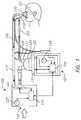
- FIG. 1is a schematic view of an example embodiment of a humidification system.
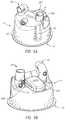
- FIGS. 2A and 2Bare perspective views of an example embodiment of a humidification system, with some features removed in FIG. 2B to show additional detail.
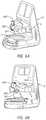
- FIG. 3is a front view of a portion of the humidification system shown in FIG. 2B .
- FIGS. 4 and 5A to 5Fare alternative views of an example embodiment of a humidification chamber.
- FIGS. 6A to 6Care alternative views of an example embodiment of a humidification system including a coupler of or associated with a base unit.
- FIG. 6Dillustrates the coupler of FIGS. 6A to 6C .
- FIG. 7illustrates an example embodiment of a circuit connector connected to a humidification chamber.
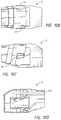
- FIGS. 8A to 8E, 9A, 9B, 10A to 10K, 11A, and 11Bare alternative views of example embodiments of circuit connectors and/or humidification chamber outlets configured to connect therewith.
- FIG. 12is a perspective view of an example embodiment of a humidification system.
- FIG. 13is an alternative view of a chamber, cartridge, and connector of the humidification system of FIG. 12 .
- FIG. 14is an exploded view of FIG. 13 showing an insert block.
- FIG. 15is a sectional view of the assembly of FIG. 13 .
- FIG. 16is an enlarged perspective view of the cartridge and insert block of FIG. 13 .
- FIGS. 17 and 18are perspective views of the insert block of FIG. 13 .
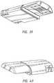
- FIGS. 19 to 22are views of the connector of FIG. 13 .
- FIG. 23is a sectional view of the connector of FIG. 13 .
- FIG. 24is an exploded view of an example embodiment of a connector similar to that of FIG. 13 , showing the components of the connector.
- FIG. 25is a sectional view of the chamber, cartridge, insert block, and a portion of the connector of FIG. 13 .
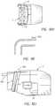
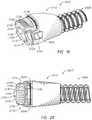
- FIG. 26is a front perspective view of another example embodiment of an insert block.
- FIG. 27is a rear perspective view of the insert block of FIG. 26 , showing exit holes for wires.
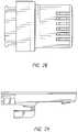
- FIG. 28is a bottom view of the insert block of FIG. 26 .
- FIG. 29is a side view of the insert block of FIG. 26 .
- FIG. 30is a sectional side view of the insert block of FIG. 26 .
- FIG. 31is a detailed image of a rotating leaf pin used in the insert block of FIG. 26 .
- FIG. 32is a front perspective view of another example embodiment of an insert block.
- FIG. 33is a rear perspective view of the insert block of FIG. 32 .
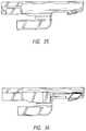
- FIG. 34is a bottom view of the insert block of FIG. 32 .
- FIG. 35is a side view of the insert block of FIG. 32 .
- FIG. 36is a sectional side view of the insert block of FIG. 32 .
- FIG. 37is a perspective view of an example embodiment of an insert block formed of multiple pieces, in which one or more of the pieces may be overmoulded.
- FIG. 38is another perspective view of the insert block of FIG. 37 .
- FIG. 39is another perspective view of the insert block of FIG. 38 .
- FIG. 40is another perspective view of the insert block of FIG. 39 .
- FIG. 41is a side view of another example embodiment of a conduit connector.
- FIGS. 42 to 44are a top views of example embodiments of a conduit connector, showing differently spaced and sized PCB contact pads.
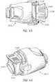
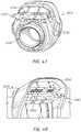
- FIGS. 45 to 47illustrate another example embodiment of a conduit connector.
- FIG. 48illustrates a portion of another example embodiment of a cartridge.
- FIGS. 49 to 50illustrate views of the insert block of FIG. 48 .
- FIG. 1shows an example breathing circuit which includes one or more medical tubes.
- a breathing circuitmay be a continuous, variable, or bi-level positive airway pressure (PAP) system or other form of respiratory therapy.
- PAPpositive airway pressure
- Gasesmay be transported in the breathing circuit of FIG. 1 as follows. Dry or relatively dry gases pass from a gases source 105 to a humidifier 107 , which humidifies the dry gases.
- the gases source 105may be, for example, a ventilator or a blower.
- the humidifier 107connects to an end 109 of an inspiratory tube 103 via a port 111 , thereby supplying humidified gases to the inspiratory tube 103 , which may be configured to deliver breathing gases to a patient.
- the gasesflow through the inspiratory tube 103 to a Y-piece 113 , and then to a patient 101 through a patient interface 115 connected to the Y-piece 113 .
- An expiratory tube 117also connects to the patient interface 115 through the Y-piece 113 and may be configured to move exhaled gases away from the patient 101 .
- the expiratory tube 117returns exhaled gases from the patient 101 to the gases source 105 .
- dry or relatively dry gasesenter the gases source 105 through a vent 119 .
- a fan 121may improve gas flow into the gases source 105 by drawing air or other gases through the vent 119 .
- the fan 121may be, for instance, a variable speed fan, where an electronic controller 123 controls the fan speed.
- the function of the electronic controller 123may be controlled by an electronic master controller 125 in response to inputs to the master controller 125 and a user-set predetermined required value (preset value) of pressure or fan speed via a dial 127 .
- the humidifier 107comprises a humidification chamber 129 containing a volume of water 130 or other suitable humidifying liquid.
- the humidification chamber 129is removable from the humidifier 107 after use to allow the humidification chamber 129 to be more readily sterilized or disposed.
- the body of the humidification chamber 129may be formed from a non-conductive glass or plastics material, but the humidification chamber 129 may also include conductive components.
- the humidification chamber 129may include a highly heat-conductive base (for example, an aluminum base) contacting or associated with a heater plate 131 on the humidifier 107 .
- the humidifier 107may also include electronic controls.
- the humidifier 107includes an electronic, analog, or digital master controller 125 .
- the master controller 125may be a microprocessor-based controller executing computer software commands stored in associated memory. In response to humidity or temperature values provided via a user interface 133 , for example, and other inputs, the master controller 125 determines when (or to what level) to energize the heater plate 131 to heat the water 130 within the humidification chamber 129 .
- Patient interfaceis a broad term and is to be given its ordinary and customary meaning to a person of ordinary skill in the art (that is, it is not to be limited to a special or customized meaning) and includes, without limitation, masks (such as tracheal mask, face masks, and nasal masks), cannulas, and nasal pillows.
- a temperature probe 135may connect to the inspiratory tube 103 near the Y-piece 113 , or directly to the Y-piece 113 or the patient interface 115 . The temperature probe 135 monitors the temperature of the flow of gases near or at the patient interface 115 .
- a heating filamentmay be used to adjust the temperature of the patient interface 115 , the Y-piece 113 , and/or the inspiratory tube 103 to raise the temperature of the flow of gases above the saturation temperature, thereby reducing the opportunity for unwanted condensation.
- exhaled gasesare returned from the patient interface 115 to the gases source 105 via the expiratory tube 117 .
- the expiratory tube 117may have a temperature probe and/or heating filament, as described above with respect to the inspiratory tube 103 , integrated with it to reduce the opportunity for condensation. Furthermore, the expiratory tube 117 need not return exhaled gases to the gases source 105 . Alternatively, exhaled gases may be passed directly to ambient surroundings or to other ancillary equipment, such as an air scrubber/filter (not shown). In certain embodiments, the expiratory tube 117 is omitted altogether.
- the system of FIG. 1may be readily adapted for other applications involving the supply of a heated and/or humidified gas flow to a user or patient, including but not limited to laparoscopy, ventilation, and the like.
- Such applicationsmay use alternative gases, operating parameters (e.g., flow, pressure, temperature, or humidity) and patient interfaces.
- Example embodiments described herein belowmay be configured for incorporation in the system of FIG. 1 , or a similar system, and the further description should be read in combination with the disclosure relating to FIG. 1 .
- FIGS. 2A and 2Billustrate a humidification apparatus 1 according to an example embodiment.
- the apparatusincludes a circuit connector 2 that pneumatically connects a medical tube or conduit 3 to an outlet 15 of a humidification chamber 4 .
- the outlet 15may terminate in a substantially horizontal portion that is angled away from a base unit 5 when the humidification chamber 4 is installed on the base unit 5 .
- the conduit 3may be an inspiratory limb of a patient circuit, i.e., configured to deliver humidified gases to a user, such as via a patient interface (not shown).
- An inlet 8 of the humidification chamber 4is configured to be fluidly connected to a source of pressurised gas.
- the inlet 8may be pneumatically coupled to a motorised fan in or associated with the base unit 5 that drives gases through the inlet 8 .
- the circuit connector 2further facilitates electrical connection to the base unit 5 via a coupler 6 .
- the coupler 6may be integrally formed with the base unit 5 or may be a separate, replaceable module or cartridge.
- the ability to change modulesmay advantageously be used to enable use of different forms of humidification chamber and/or circuit connector. Additionally or alternatively, by comprising control circuitry, the module may be changed to alter the operation of the humidification apparatus 1 .
- the conduit 3may comprise one or more resistive heating wires that provide for heating of gases flowing through the conduit and/or sensor wires that electrically or otherwise facilitate communication of signals relating to one or more parameters of the system.
- electrical connectionis used to distinguish from “pneumatic connection” and should not be construed in a limiting way.
- the circuit connector 2may more generally communicatively and/or electrically connect the conduit 3 (and any associated peripheral equipment, such as sensors, for example) to the base unit 5 , such as via the coupler 6 .
- the circuit connector 2may include at least one button or switch 10 , which may be manually depressed to enable the circuit connector 2 (and hence also the conduit 3 ) to be disconnected from the humidification chamber 4 .
- the circuit connector 2 and the outlet 15 of the humidification chamber 4may become lockably engaged on connection therebetween with the at least one button or switch 10 being used to subsequently allow for disengaging the circuit connector 2 from the humidification chamber 4 . Any suitable connection may be used.
- the base unit 5further includes a panel 9 which may be used to mount a user display and/or controls. For example, various dials, switches, and other input means may be used to control operation of the device. Additionally or alternatively, a touch screen display may be used.
- the user displaymay display parameters of the system, warnings in the event of any errors or malfunctions, or prompts where user action is required, etc. Where a touch screen display is used, the same display may be used to present information to a user and receive inputs from a user, at least in part.
- the base unit 5includes a heater plate 11 as shown in FIG. 3 , which is controllably powered to heat the contents of the humidification chamber 4 .
- the humidification chamber 4may comprise a base plate 19 formed from a highly heat conductive material.
- the two surfacesmay be biased towards each other.
- a lip 12extends outwards from, or proximate to, the base plate 19 of the humidification chamber 4 and is received under a projecting rim 13 of the base unit 5 as the humidification chamber 4 is slid onto the base unit 5 .
- the heater plate 11may be spring mounted such that the heater plate 11 is urged upwards into the base plate 19 of the humidification chamber 4 , with the lip 12 acting against the projecting rim 13 .
- the base unit 5further includes a sprung latch bar 14 .
- the latch bar 14is first depressed such that the lip 12 is able to be received under the projecting rim 13 . This may be conveniently performed by positioning the base plate 19 of the humidification chamber 4 on the latch bar 14 and pressing the humidification chamber 4 downward and then toward the rear of the base unit 5 .
- the latch bar 14can raise and act as a mechanical stop to prevent unintended removal of the humidification chamber 4 from the base unit 5 .
- the latch bar 14To disengage the humidification chamber 4 from the base unit 5 , the latch bar 14 must first be depressed and then the humidification chamber 4 pulled away from the base unit 5 by sliding the base plate 19 of the humidification chamber 4 across the surface of the heater plate 11 and then onto the latch bar 14 .
- the humidification chamber 4may include gripping portions 16 that make it easier for a user to grip the humidification chamber 4 as it is pulled away from the base unit 5 .
- the outlet 15 of the humidification chamber 4may be oriented so as to be substantially parallel to the direction of motion of the humidification chamber 4 as it is slid on or off of the base unit 5 , at least at the end of the outlet 15 distal from the humidification chamber 4 .
- the circuit connector 2 and the outlet 15are configured to lockably engage, which prevents separation of the circuit connector 2 from the outlet 15 while the humidification chamber 4 is slid onto the base unit 5 .
- the conduit 3 and the humidification chamber 4may be preassembled for shipping, thereby eliminating one step from the setup process. Irrespective of the order of assembly, electrical or other connections between the conduit 3 and/or the circuit connector 2 to the coupler 6 and/or the base unit 5 may be made as the circuit connector 2 engages with the coupler 6 .
- disassemblymay be performed in different sequences. More particularly, the circuit connector 2 may firstly be removed from the outlet 15 of the humidification chamber 4 , followed by removal of the humidification chamber 4 from the base unit 5 . Alternatively, the humidification chamber 4 may be removed from the base unit 5 while the circuit connector 2 is still attached to the outlet 15 of the humidification chamber 4 . The latter option may advantageously help reduce the likelihood of a spill of fluids during disassembly and disposal of the consumables from the base unit 5 .
- various guidesmay be provided to control the orientation and/or position thereof relative to one another. More particularly, to enable the humidification chamber 4 to be slid into engagement with the base unit 5 and the coupler 6 , various orientation features may be provided on the humidification chamber 4 and/or the coupler 6 such that, particularly when the circuit connector 2 is attached to the outlet 15 , the component parts are brought readily and easily into alignment. For example, the humidification chamber 4 is able to be brought into full engagement with the base unit 5 such that the circuit connector 2 is also brought into engagement with the coupler 6 .
- circuit connector 2 and/or the coupler 6may additionally or alternatively include orientation features to help ensure that the circuit connector 2 is connected to the humidification chamber 4 with the circuit connector 2 properly oriented to allow for easy coupling of the circuit connector 2 and the humidification chamber 4 to the base unit 5 and the coupler 6 .
- FIGS. 5A to 5Fare various alternative views of an example embodiment of the humidification chamber 4 .
- FIGS. 6A to 6Care alternative views of the coupler 6 .
- the humidification chamber 4may include a nose portion 201 and guide wings 202 . These features are configured to engage with a contoured recess 301 and slots 302 , respectively, in the coupler 6 (see FIGS. 6A to 6C ).
- a width of the nose portion 201is defined along the X-axis
- a length of the nose portion 201is defined along the Y-axis
- a height of the nose portion 201is defined along the Z-axis.
- the nose portion 201has a smaller width at a first end than at a second end of the nose portion 201 , the first end of the nose portion 201 being configured to be received first in the recess 301 . This provides some tolerance as to the position of the humidification chamber 4 along the X-axis (as well as rotationally about the Z-axis), in order for the nose portion 201 to be initially received in the recess 301 .
- the wider second end of the nose portion 201may serve to refine the location of the nose portion 201 (and hence also the humidification chamber 4 ) along the X-axis (and rotationally about the Z-axis) in that the spacing or tolerance between the nose portion 201 and the recess 301 becomes reduced, thereby reducing the extent of relative movement.
- the recess 301is configured such that the inclined sidewalls of the nose portion 201 abut corresponding and similarly inclined sidewalls of the recess 301 . Having the sidewalls of the nose portion 201 and the sidewalls of the recess 301 configured in this manner controls the position of the humidification chamber 4 not only along the X-axis but also rotationally about the Y- and/or Z-axes, since movement of the nose portion 201 along the X-axis in at least two locations along the length of the nose portion 201 , and also along the height of the nose portion 201 , is substantially inhibited.
- the sidewalls of the nose portion 201do not abut the sidewalls of the recess 301 .
- the configurationwill still assist with initial insertion of the nose portion 201 into the recess 301 and at least significantly restrict movement of the nose portion 201 along the X-axis at the second end of the nose portion 201 , although some rotational movement about the Z-axis may be possible.
- the sidewalls of the nose portion 201are substantially parallel and the recess 301 narrows along its length along the Y-axis from its opening to a width at least as great as that of the nose portion 201 .
- the nose portion 201 in combination with the recess 301may additionally or alternatively provide tolerance along at least the Z-axis with regards to the initial placement of the humidification chamber 4 . Further, according to particular embodiments, the nose portion 201 and the recess 301 may cooperate to refine the location of the humidification chamber 4 along the Z-axis and/or rotationally about the X- and/or Y-axes.
- This toleranceis provided in a similar manner to the tolerance in the X-direction.
- the height of the nose portion 201is lower at the first end than at the second end, the height being measured from the base plate 19 .
- the recess 301is similarly contoured, thereby providing for easy initial insertion followed by the refinement of position along the Z-axis on continued insertion of the humidification chamber 4 into full engagement with the base unit 5 .
- the opposing walls of the substantially downwardly facing underside of the recess 301may not abut along the length thereof with the upwardly facing topside of the nose portion 201 .
- one or the othermay be orientated to be substantially parallel to the heater plate 11 with similar drawbacks to those mentioned previously. More particularly, while initial insertion may be facilitated, the degree of refinement of the position of the humidification chamber 4 along the Z-axis may be reduced and there may be less control to ensure that the base plate 19 is parallel to the heater plate 11 .
- the engagement of the guide wings 202 with the slots 302provides sufficient movement restriction to reduce the need for alignment and engagement of the base plate 19 with the heater plate 11 via the projecting rim 13 .
- the base unit 5may not include a projecting rim 13 .
- the nose portion 201may be provided in the absence of the guide wings 202 .
- the use of the guide wings 202is preferred, at least in embodiments in which the heater plate 11 is spring mounted, so as to improve control of the positioning of the humidification chamber 4 along at least the Z-axis and/or to ensure that the heater plate 11 is substantially parallel to the base plate 19 .
- the guide wings 202may be provided in the absence of the nose portion 201 , but such a configuration is less preferable, since the nose portion 201 may more readily assist in the initial locating of the humidification chamber 4 and also perform the initial coarse adjustment thereof to refine the position, with the possibility of the guide wings 202 then being used to further refine the position of the humidification chamber 4 along the Z-axis and controlling the orientation about at least the X- and Y-axes.
- the guide wings 202may for example be mounted on a substantially rigid mount that extends vertically from the humidification chamber 4 , with the guide wings 202 extending laterally therefrom.
- the substantially rigid mountmay be substantially planar, with a generally T-shaped cross-section. However, to increase strength and rigidity, the mount may comprise more substantial element(s) having thickness, but a thickness that does not generally bring the mount into direct contact with the coupler 6 .
- the guide wings 202do not extend right to the first end of the nose portion 201 . Instead, they are spaced therefrom, thereby enabling initial engagement between the nose portion 201 and the recess 301 without engagement of the guide wings 202 with the slots 302 , this only occurring on continued engagement of the humidification chamber 4 with the base unit 5 after the relative positions between the two have been refined.
- the nose portion 201may be in the form of a contoured recess and vice versa such that a contoured recess of the humidification chamber 4 receives a nose portion or projection of the coupler 6 .
- the guide wings 202may be substituted with grooves that receive wings or other projections on the coupler 6 .
- Other arrangements that perform the same functionmay also be used.
- the circuit connector 2may include a cutout 403 configured to accommodate a substantially vertical portion of the outlet 15 . Again, this helps to ensure that the circuit connector 2 is correctly oriented as it is inserted onto the end of the outlet 15 since full insertion is only possible with correct alignment. Further, this arrangement provides for a stronger coupling and allows for electrical connection as will be described below. Again, at least an initial portion of the cutout 403 may be angled or curved such that the first part of the cutout 403 that receives the vertical portion of the outlet 15 is wider than the outlet 15 , providing some tolerance as to the required initial alignment. However, where the outlet 15 is generally of a circular cross-section, this may not be required as some tolerance is inherently provided due to the circular shape of the outlet 15 .
- the circuit connector 2may additionally or alternatively include an angled cutout 408 that receives a similarly angled protrusion 409 on the outlet 15 . Again this serves to obtain and secure orientation of the circuit connector 2 and the outlet 15 relative to one another.
- guide meansmay be incorporated in the heater plate 11 and/or the base plate 19 of the humidification chamber 4 .
- a ridge in the heater plate 11may be configured to be received in a slot in the base plate 19 of the humidification chamber 4 , or vice versa.
- FIGS. 2A, 2B, 6C, and 7A first embodiment of the circuit connector 2 is illustrated in FIGS. 2A, 2B, 6C, and 7 .
- a first end of the circuit connector 2(see FIG. 2B ) is configured to receive and pneumatically seal an end of a respiratory tube or conduit 501 (see FIG. 6C ).
- the circuit connector 2may comprise a main body 502 and an extending portion 504 .
- the interior of the main body 502defines a channel that connects the conduit 501 to the horizontal portion of the outlet 15 to provide a continuous flow passage when assembled.
- a seale.g., an O-ring, double O-ring, or lip seals
- the coupler 6is shown including a shroud 505 which receives and covers the extending portion 504 . This may help to reduce or eliminate the likelihood of any spilled liquid coming into contact with electrical components of the circuit connector 2 and also serves to strengthen and rigidify the coupling. Further, the shroud 505 may assist in bringing the circuit connector 2 into engagement with the outlet 15 of the humidification chamber 4 and/or into engagement with the base unit 5 . More particularly, the shroud 505 provides a visual indication as to where the circuit connector 2 should be positioned. Further, the shroud 505 may provide some physical control over the location of the circuit connector 2 .
- the extending portion 504 of the circuit connector 2is received against a portion of the wall of the shroud 505 opposing the heater plate 11 . This may occur particularly where the heater plate 11 is spring-mounted so as to bias the heater plate 11 towards the shroud 505 .
- at least the height (i.e., along the Z-axis) of the circuit connector 2may be controlled. Having the shroud 505 provide a curved opposing wall may assist in locating the circuit connector 2 along the X-axis since the circuit connector 2 will be urged towards the center of the arc formed by the shroud 505 .
- the physical locating function of the shroud 505is yet further improved by having the shroud 505 define a wall that at least partially encloses the circuit connector 2 so as to control not only an upper limit for the position of the circuit connector 2 but an actual location thereof.
- FIGS. 8A to 8Cillustrate an embodiment of a lockable but releasable coupling between the circuit connector 2 and the outlet 15 .
- the circuit connector 2includes the button 10 that may be manually actuated such as by a thumb or finger to enable the circuit connector 2 to be removed from the outlet 15 .
- the button 10is formed from a resiliently elastic material and has a portion configured to be received in a recess 601 formed in the outer wall of the outlet 15 . Depression of the button 10 disengages an engaging portion of the button 10 from the recess 601 .
- FIGS. 8D and 8Eillustrate an alternative embodiment where the button 10 is formed from a substantially rigid material but may be spring mounted. Depression of the button 10 acts against the spring and disengages an engaging portion 602 of the button 10 from recesses in an outer wall of the outlet 15 .
- FIGS. 9A and 9Billustrate an alternative embodiment where the button 10 , or at least the engaging portion 602 thereof, is resiliently elastic whereby at least a portion of the button 10 deforms to disengage the engaging portion 602 from recesses 601 in the outlet 15 .
- FIGS. 10A to 10Hillustrate an alternative embodiment of the circuit connector 2 .
- the buttons 10are positioned on sides of the circuit connector 2 , as this may be more convenient in being placed at natural contact points for a user when attempting to disconnect the circuit connector 2 from the outlet 15 .
- the buttons 10are integral with or operably coupled to an elastically deformable ring 701 . Depression of the buttons 10 disengages the ring 701 from recesses formed in at least one of the upper and lower outer surfaces of the outlet 15 , allowing the circuit connector 2 to be removed.
- FIGS. 10A to 10Halso show a cavity 702 for housing electrical or other connections.
- protrusions 705may be used in the outlet 15 as shown in cross-section in FIG. 10I .
- the top of the ring 701rests behind (or closer to the base unit 5 than) the protrusion 705 .
- the buttons 10are depressed to deform the ring 701 such that the top of the ring 701 rises above the level of the protrusion 705 and then the circuit connector 2 can be removed from the outlet 15 .
- FIGS. 10J and 10Kwherein the electrical terminal is in the form of an edge card 901 . Further shown is a groove 902 configured to receive a seal such as an o-ring.
- Example electrical connections 801are shown in FIGS. 8A and 8B .
- the electrical connectionsmay be provided in the extending portion 504 of the circuit connector 2 such that they extend beyond the pneumatic connection and electrically and/or communicatively couple to a cooperative connector 802 on the coupler 6 as shown in FIG. 6D .
- the electrical and other connectionsmay be formed by blade contacts that are received in respective recesses in the coupler 6 that house contacts for connecting thereto.
- Other connectorssuch as pins may alternatively be used but blade contacts are advantageous in providing some tolerance in the exact relative positioning of the blades in the recesses. In the embodiment shown, some vertical tolerance is provided for.
- the electrical contactscomprise one or more pogo or spring pin contacts that include spring-mounted pins housed in passages that allow them to vary the extent to which they protrude from the housing, thereby providing tolerance in the relative positions of the circuit connector 2 and the coupler 6 along the axes of the pins. Further, the ability for the pins to become depressed may make insertion of the pins into the apertures that house cooperating or mating connectors easier.
- the electrical connectionscomprise edge card connectors or card edge connectors, wherein a first part of the connector has one or more conductive tracks provided on a printed circuit board and configured to make contact with one or more pins of a second part of the connector.
- FIG. 11Ais a cross-sectional view of an alternate embodiment of the circuit connector 2 engaged with the outlet 15 of the humidification chamber 4 .
- the circuit connector 2has a male connection such that at least a portion of the circuit connector 2 is received inside the outlet 15 .
- An o-ring 1005 or other sealis used to seal between the male parts and the inside wall of the outlet 15 .
- FIG. 11Bshows a view similar to that of FIG. 11A but modified such that the outlet 15 is configured as the male part that mates with the inner wall of the inlet of the circuit connector 2 .
- an o-ring 1005 or other sealmay be used to reduce or eliminate the likelihood of leakage.
- the humidification system 2000may have any suitable configuration.
- the humidification system 2000may be used in conjunction with other components for supplying heated and/or humidified gases for continuous, variable, or bi-level positive airway pressure (PAP) or any other type of respiratory therapy. It also may be used in conjunction with devices for surgical applications, such as for laparoscopic surgery or the like.
- PAPbi-level positive airway pressure
- the illustrated humidification system 2000comprises a base 2002 that receives a humidification chamber 2004 .
- a supply conduit 2006 and a delivery conduit 2008may be connected to the humidification chamber 2004 .
- the supply conduit 2006may deliver to the humidification chamber 2004 a flow of gases to be humidified.
- the delivery conduit 2008may deliver to a user or patient the flow of gases after they have been humidified within the chamber 2004 .
- the base 2002includes an electrical connection to one or both of the supply conduit 2006 and the delivery conduit 2008 (e.g., an inspiratory limb).
- the base 2002comprises a cartridge or coupler 2010 .
- the cartridge or coupler 2010may be integrally formed with the base 2002 or may be a separate, replaceable module or cartridge.
- One or both of the conduits 2006 , 2008may include one or more wires.
- the wiresmay comprise one or more resistive heating wires that provide for heating of the conduit wall and/or gases flow.
- the wiresmay comprise one or more sensor wires that facilitate the communication of signals relating to one or more parameters of the system 2000 .
- the term “electrical connection”is used in its broadest meaning and should include light signals via fibre optics or the like, for example but without limitation.
- the illustrated delivery conduit 2008comprises a connector 2012 .
- the connector 2012facilitates the electrical connection between the conduit 2008 and the cartridge 2010 .
- the connector 2012also facilitates a pneumatic connection between the conduit 2008 and the chamber 2004 .
- the connector 2012facilitates both the electrical connection between the base 2002 (through the cartridge 2010 ) and the conduit 2008 as well as the pneumatic connection between the chamber 2004 and the conduit 2008 .
- the connector 2012 in the illustrated configurationis constructed to connect in a horizontal direction (i.e., a direction parallel to a direction of insertion of the chamber 2004 into or onto the base 2002 ).
- the connector 2012is constructed to connect electrically to the cartridge 2010 in the horizontal direction.
- the connector 2012is constructed to connect pneumatically to the chamber 2004 in the horizontal direction.
- the connector 2012is constructed to connect to both the cartridge 2010 and the chamber 2004 in the same horizontal direction.
- the cartridge 2010may include a hood portion 2020 that overlies an electrical connector (e.g., an electrical junction 2034 as shown in FIG. 16 ) of the cartridge 2010 .
- the hood portion 2020may extend forward of the base 2002 in a generally horizontal direction.
- the hood portion 2020may include a recess 2022 along a vertically extending portion.
- the recess 2022is sized, positioned and configured to receive a portion of the connector 2012 that comprises a release button 2024 .
- at least a portion of the hood 2020extends further along an upper portion of the connector 2012 (when connected to the cartridge 2010 ) from the base 2002 relative to the location of the release button 2024 on the connector 2012 .
- Other configurationsare possible.
- an insert block 2030may facilitate the electrical connection between the connector 2012 and the cartridge 2010 .
- droplets of water or other moisturemay be present on the connector 2012 .
- the insert block 2030helps to isolate the cartridge 2010 from the water or other moisture while facilitating the desired electrical connection between the connector 2012 and the cartridge 2010 .
- the insert block 2030may be mounted to the connector 2012 or to the cartridge 2010 . In some configurations, the insert block 2030 is not mounted to either of the connector 2012 or the cartridge 2010 . In the illustrated configuration, the insert block 2030 is mounted to the cartridge 2010 . By mounting the insert block 2030 to the cartridge 2010 , the likelihood of the insert block 2030 becoming misplaced during changing of the conduit 2008 or the like is significantly decreased. By not mounting the insert block 2030 to the connector 2012 , changing of the conduit 2008 is simplified and there is less waste as compared to an insert block 2030 that might be discarded with the conduit 2008 following each use.
- the insert block 2030has a first electrical junction 2032 and a second electrical junction 2034 .
- the first electrical junction 2032is sized, positioned and configured to engage with an electrical connector of the cartridge 2010 .
- the second electrical junction 2034is sized, positioned and configured to engage with electrical contacts 2036 (see FIG. 14 ) of the connector 2012 .
- the first electrical junction 2032 and the second electrical junction 2034may be joined together in any suitable manner.
- the insert block 2030transforms a generally horizontal connection between the first electrical junction 2032 and an electrical connector of the cartridge 2010 into a generally vertical connection between the second electrical junction 2034 and the electrical contacts 2036 of the connector 2012 .
- the insert block 2030comprises a body 2040 .
- the body 2040is sized and configured to be received within the hood 2020 .
- the body 2040is sized and configured to be retained within the hood 2020 .
- the hood 2020comprises one or more alignment features 2042 .
- the alignment features 2042 of the hood 2020comprise rails 2042 .
- the rails 2042may have any suitable configuration. In the illustrated configuration, two rails 2042 are aligned to each other on diametrically opposed sides of the hood 2020 .
- the illustrated cartridge 2010also comprises a flange 2044 .
- the flange 2044may be integrally formed with the rails 2042 or may be a separate feature from the rails 2042 .
- the flange 2044extends generally horizontally and projects forward from a rear wall of the cavity that receives the connector 2012 .
- the flange 2044is enshrouded by the hood 2020 .
- the flange 2044has a stepped configuration with a distal end having a reduced thickness relative to a proximal end, wherein the proximal end is closer to the rear wall of the cavity than the distal end.
- the body 2040includes a mounting boss 2046 .
- a recess 2048may be defined between the mounting boss 2046 and another portion of the body 2040 that extends to the first electrical junction 2032 .
- the recess 2048may be sized and configured to receive at least a portion of the flange 2044 .
- an engagement portion 2050 of the body 2040may be spaced apart from the mounting boss 2044 by the recess 2048 .
- Other configurationsare possible.
- the mounting boss 2044may include channels 2052 .
- the channels 2052may be sized, positioned and configured to receive the rails 2042 .
- the channels 2052may have a shorter length than the length of the rails 2042 such that a significant portion of the rails 2042 are exposed beyond the mounting boss 2044 when the insert block 2030 has been secured within the hood 2020 .
- the engagement portion 2050 of the body 2040may comprise one or more retention elements 2054 .
- the one or more retention elements 2054may each comprise a deflectable tab.
- At least one deflectable tab 2054may be positioned on each opposing side of the body 2040 .
- the body 2040has a deflectable tab 2054 disposed on each lateral side of the body 2040 .
- the tabs 2054may include a catch element 2056 .
- the catch element 2056may extend laterally away from the body 2040 .
- the catch element 2056may extend generally normal from a recess that spaces at least a portion of the deflectable tab 2054 from the body 2040 .
- a proximal portion of the deflectable tab 2054including the catch element 2056 , may be shaped to encourage deflection of the tab 2054 inwardly toward the body 2040 during insertion of the insert block 2030 into the hood 2020 .
- the proximal surface of the catch element 2056may taper when viewed from the top.
- the body 2040includes a distal end 2060 . Proximally of the distal end 2060 , an upper surface of the body 2040 may be shaped to match the inner surface of the hood 2020 . In the illustrated configuration, both are curved.
- the distal end 2060 of the body 2040may be recessed within the hood 2020 . As shown in FIG. 15 , the distal end 2060 may be shaped and configured to complement an adjoining end of the connector 2012 . For example, in the illustrated configuration, the distal end 2060 of the body 2040 may taper slightly.
- a contact surface 2062may be positioned between the distal end 2060 and the mounting boss 2046 . In the illustrated configuration, the contact surface 2062 faces downward. In some configurations, the contact surface 2062 is generally planar.
- the contact surfaceincludes one or more openings through which contact terminals 2064 may extend.
- the contact terminals 2064may define at least a portion of the second electrical junction 2034 .
- the contact terminals 2064may have any suitable configuration.
- the contact terminals 2064are sprung terminals that have been configured to minimize or reduce surfaces to which water may adhere. In some configurations, the contact terminals 2064 are sprung terminals that have been configured to minimize or reduce surfaces upon which a cloth may catch during wiping or cleaning. In a relaxed state, the contact terminals 2064 advantageously protrude downward beyond the contact surface 2062 . When compressed, the contact terminals 2064 may be at least partially deflected into the body 2040 .
- the body 2040may include an encircling groove 2066 .
- the groove 2066may be positioned rearward of a post 2068 that connects the mounting boss 2046 to the engagement portion 2050 .
- the groove 2066may receive a sealing component 2070 .
- the sealing component 2070may be a seal, an o-ring or the like. In some configurations, neither the groove 2066 nor the sealing component 2070 are present.
- the insert block 2030may be inserted into the hook 2020 .
- the rails 2042are positioned within the channels 2052 .
- the insert block 2030is slid proximally until the flange 2044 is received within the recess 2048 .
- the sealing component 2070may be compressed between the engagement portion 2050 and the surrounding portions of the cartridge 2010 .
- features on an inner surface of the hood 2020may cause the tabs 2054 to deflect inwardly toward the body 2040 until the catch elements 2056 are proximal of the features on the inner surface, at which point the tabs 2054 may return to a relaxed state with the catch elements 2056 positioned proximally of the features on the inner surface.
- any suitable configuration to secure the insert block 2030 within the hood 202may be used.
- the first electrical junction 2032e.g., receptacles
- the second electrical junction 2034e.g., the terminals 2064
- the terminals 2064is easily accessed for drying, wiping, cleaning or the like.
- coatings applied to the terminals 2064 , or the likewater and other liquids are not likely to remain on or adhere to the terminals 2064 .
- the connector 2012may be secured to the end of the conduit 2008 in any suitable manner.
- the connector 2012generally comprises an inner plug 2100 .
- the conduit 2008may be threaded onto the illustrated inner plug 2100 and secured thereto using overmoulding or any other suitable technique.
- a seal 2102may be positioned on an outer surface of the inner plug 2100 .
- the seal 2102may be used to help form a pneumatic seal with an inner surface of a port of the chamber 2004 .
- the inner plug 2100also carries a printed circuit board 2104 .
- the printed circuit board 2104may include contact pads 2106 .
- the contact pads 2106may have any suitable configuration.
- the contact pads 2106are sized, positioned and configured to be brought into contact with the terminals 2064 of the second electrical junction 2034 of the insert block 2030 . In the illustrated configuration, there are six contact pads 2106 that are spaced equally from each other. The contact pads 2106 may be spaced so as to decrease the likelihood of shorting due to the presence of water droplets.
- example embodiments of the connector 2012may have the contact pads 2106 sized, positioned, and spaced according to various designs.
- FIG. 42shows an example embodiment of the conduit connector 2012 , showing the contact pads 2106 uniformly sized and spaced, where the contact pads 2106 are positioned in the order of heater pad, identification pad, sensor pad, sensor pad, identification pad, heater pad (which can be designated HISSIH), each suited for connection to a corresponding wire.
- FIG. 43shows an example embodiment of the conduit connector 2012 , showing the contact pads 2106 uniformly spaced, and also in HISSIH order, but with longer heater pads that may help to ensure that the heater wire connections are made before, and broken after, the identification and sensor wire connections.
- FIG. 42shows an example embodiment of the conduit connector 2012 , showing the contact pads 2106 uniformly sized and spaced, where the contact pads 2106 are positioned in the order of heater pad, identification pad, sensor pad, sensor pad, identification pad, heater pad (which can be designated HISSIH), each suited for connection to a
- FIG. 44shows an example embodiment of the conduit connector 2012 , with the contact pads 2106 also having longer heater pads, but with non-uniformly spaced pads in the order SSIIHH, from top to bottom, which increases the space between the sensor pads and the heater pads.
- the first sensor pad(at the top, as illustrated in FIG. 44 ) is suited for connection to a positive sensor wire and the second sensor pad is suited for connection to a negative sensor wire, which helps to maximize the space between the positive sensor pad and the heater pads.
- an embodiment of the connector 2012has the contact pads 2106 in the order SSIIHH, from top to bottom, with longer heater pads and a gap between the heater pads and the other pads, again helping to maximize the space between the heater pads and the sensor pads.
- FIG. 48illustrates a portion of an alternate embodiment of the cartridge 2010 , showing the insert block 2030 with the electrical junction or contacts 2034 under the hood portion 2020 .
- the electrical contacts 2034have spacing corresponding to the spacing of the contact pads 2106 of FIG. 47 , in particular with a gap between the contacts that correspond to the heater pads and the contacts that correspond to the identification and sensor pads.
- FIGS. 49 and 50provide additional views of the alternate embodiment of the insert block 2030 shown in FIG. 48 .
- the inner plug 2100may be retained within a cavity defined within a front cover 2110 and a back cover 2112 .
- the front cover 2110 and the back cover 2112may be coupled together or coupled to the inner plug 2100 to generally enclose the inner plug 2100 within the covers 2110 , 2112 .
- the back cover 2112clips onto a portion of the inner plug 2100 and the front cover 2110
- the front cover 2110also clips onto a portion of the inner plug 2100 .
- a seam between the front cover 2110 and the back cover 2112is obscured by having at least a portion of one of the front cover 2110 and the back cover 2112 overlie a corresponding portion of the other of the two covers 2110 , 2112 .
- the front cover 2110includes a recess 2114 over which a lip 2116 of the back cover 2112 slips.
- the lip 2116obscures the seam between the two covers 2110 , 2112 and an abutting relationship between the two covers 2110 , 2112 reduces the likelihood of water infiltrating the connector 2012 .
- a locking ring 2118may be secured between the front cover 2110 and the inner plug 2100 .
- the locking ring 2118includes the release buttons 2024 .
- the release buttons 2024protrude through openings 2120 provided in the front cover 2110 and/or the rear cover 2112 .
- the locking ring 2118is configured to latch onto a port of the chamber 2004 and the locking ring 2118 may be deflected by squeezing the release buttons 2024 toward each other, which allows for removal of the locking ring 2118 (and, therefore, the connector 2012 ) from the port of the chamber 2004 .
- the illustrated front cover 2110has a slightly different configuration from the configuration illustrated in FIG. 24 .
- a distal end 2120 of the front cover 2110may have a sloping face 2122 .
- the sloping face 2122may result from the top portion of the front cover 2110 extend further distally than the bottom portion of the front cover 2110 .
- the sloping face 2122is generally planar. In some configurations, the sloping face 2122 may be curvilinear. Other configurations are possible.
- the printed circuit board 2104may be supported by the front cover 2110 .
- the front cover 2110incorporates a support region 2125 that may be generally surrounded by an outer surface 2124 .
- the support region 2125may underlie the printed circuit board 2104 .
- the support region 2125may provide support to the printed circuit board 2104 to reduce the likelihood of flexure or deflection of the printed circuit board 2104 during connection and use of the connector 2012 .
- the support regionmay comprise one or more ribs or the like.
- the support regioncomprises a ledge that is formed around a rim that generally encircles the printed circuit board 2104 .
- the illustrated ledgeis recessed such that the printed circuit board 2104 is either recessed or flush with the surrounding portion of the front cover 2110 .
- the one or more ribsmay extend under a more central portion of the printed circuit board 2104 and may define supports for at least a central portion of the printed circuit board 2104 . Any number of ribs may be used. In some configurations, other forms of support (bosses, plateaus or the like) may be used. In some configurations, no central supports are used.
- the front cover 2110also comprises at least one channel 2126 .
- the front cover 2110includes two channels 2126 .
- the illustrated channels 2126are generally diametrically opposed.
- the channels 2126align with and receive the rails 2042 of the hood 2020 .
- the channels 2126may help to align the connector 2012 during coupling with the cartridge 2010 .
- the channels 2126 and the rails 2042also help to resist vertical movement (e.g., up and down), twisting (e.g., rotation relative to the axis of the lumen) and yawing (e.g., rotation relative to an axis normal to the axis of the lumen) of the connector 2012 relative to the cartridge 2010 when the two are coupled together.
- the front cover 2110comprises a furrow 2128 .
- the furrow 2128extends over at least an upper portion of the front cover 2110 .
- the furrow 2128has a lateral expanse that is at least as great as the width of the printed circuit board 2104 (see FIG. 20 ).
- the furrow 2128helps to divert away from the printed circuit board 2104 liquids that may be spilled onto the connector 2012 .
- the furrow 2128is thus proximal of the printed circuit board 2104 and may be recessed into the front cover 2110 such that at least a lip is defined between the furrow 2128 and the printed circuit board 2104 .
- Other configurationsare possible.
- the inner plug 2100defines a lumen 2130 .
- the lumen 2130is in fluid communication with the conduit 2008 .
- the lumen 2130has a distal end 2132 .
- the distal end 2132has a non-normal configuration. In other words, the distal end 2132 is not simply squared off relative to an axis of the lumen 2130 .
- the distal end 2132is configured to complement the inner shape of a port of the humidification chamber 2004 within which it will be inserted.
- the distal end 2132 of the lumen 2130will slope and extend as far into the port as possible to improve the ability of condensate to drain back into the humidification chamber 2004 . This is most clearly shown in FIG. 15 .
- the distal end 2132 of the lumen 2130has a sloping configuration. In the illustrated configuration, the distal end 2132 of the lumen 2130 slopes at a different slope relative to the sloping face 2122 of the front cover 2110 .
- the top of the lumen 2130projects further distally relative to the bottom of the lumen 2130 .
- the top of the lumen 2130projects forward of a forwardmost portion of the sloping face 2122 of the front cover 2110 .
- the top of the lumen 2130projects further distally than any portion of the front cover 2110 .
- the front cover 2110projects distally of the bottom portion of the lumen 2130 but the top portion of the lumen 2130 projects further distally than the upper portion of the front cover 2110 .
- a recess angle Rmay be defined.
- the recess angle Rmay be the angle when viewed from the side between the upper portion of the front cover 2110 and the upper portion of the lumen 2130 .
- the recess angle Rmay be 18 degrees in some configurations. It is believed that, if the recess angle R is greater than 18 degrees and if condensate is drained from the conduit 2008 with the connector 2012 upside down (i.e., with the printed circuit board 2104 horizontal and the contact pads 2106 facing the floor), the likelihood of condensate dripping back onto the printed circuit board 2104 is greatly reduced or eliminated.
- the outer support surface 2124may be flared, i.e., wider at the distal end 2120 than by the furrow 2128 . This flaring helps to ensure that the channels 2126 are properly vertically aligned with the rails 2042 during insertion of the connector 2012 under the hood 2020 .
- the chamber 2004includes a port 2138 .
- the port 2138terminates in an opening 2140 .
- the distal end 2132 of the lumen 2130is well within the port 2138 at the time the printed circuit board 2104 approaches contact with the terminals 2064 of the insert block 2030 .
- the electrical connection between the printed circuit board 2104 and the insert block 2030will break before the pneumatic connection between the lumen 2130 and the port 2138 will break. In other words, the electrical connection breaks before the pneumatic connection.
- the pneumatic connectionwill be established before the electrical connection. More particularly, the lumen 2130 and the port 2138 will mate before the terminals 2064 contact the pads 2106 of the printed circuit board 2104 .
Landscapes
- Health & Medical Sciences (AREA)
- Heart & Thoracic Surgery (AREA)
- General Health & Medical Sciences (AREA)
- Public Health (AREA)
- Anesthesiology (AREA)
- Biomedical Technology (AREA)
- Pulmonology (AREA)
- Hematology (AREA)
- Life Sciences & Earth Sciences (AREA)
- Animal Behavior & Ethology (AREA)
- Veterinary Medicine (AREA)
- Engineering & Computer Science (AREA)
- Emergency Medicine (AREA)
- Air Humidification (AREA)
- Optical Communication System (AREA)
- Separation By Low-Temperature Treatments (AREA)
- Massaging Devices (AREA)
- Respiratory Apparatuses And Protective Means (AREA)
- Electrotherapy Devices (AREA)
- Measuring And Recording Apparatus For Diagnosis (AREA)
Abstract
Description
Claims (25)
Priority Applications (1)
| Application Number | Priority Date | Filing Date | Title |
|---|---|---|---|
| US15/105,531US10828482B2 (en) | 2013-12-20 | 2014-12-19 | Humidification system connections |
Applications Claiming Priority (4)
| Application Number | Priority Date | Filing Date | Title |
|---|---|---|---|
| US201361919485P | 2013-12-20 | 2013-12-20 | |
| US201462059339P | 2014-10-03 | 2014-10-03 | |
| PCT/NZ2014/050024WO2015093989A1 (en) | 2013-12-20 | 2014-12-19 | Humidification system connections |
| US15/105,531US10828482B2 (en) | 2013-12-20 | 2014-12-19 | Humidification system connections |
Related Parent Applications (1)
| Application Number | Title | Priority Date | Filing Date |
|---|---|---|---|
| PCT/NZ2014/050024A-371-Of-InternationalWO2015093989A1 (en) | 2013-12-20 | 2014-12-19 | Humidification system connections |
Related Child Applications (1)
| Application Number | Title | Priority Date | Filing Date |
|---|---|---|---|
| US17/061,408ContinuationUS11826538B2 (en) | 2013-12-20 | 2020-10-01 | Humidification system connections |
Publications (2)
| Publication Number | Publication Date |
|---|---|
| US20160310689A1 US20160310689A1 (en) | 2016-10-27 |
| US10828482B2true US10828482B2 (en) | 2020-11-10 |
Family
ID=53403191
Family Applications (3)
| Application Number | Title | Priority Date | Filing Date |
|---|---|---|---|
| US15/105,531Active2036-10-31US10828482B2 (en) | 2013-12-20 | 2014-12-19 | Humidification system connections |
| US17/061,408Active2035-08-12US11826538B2 (en) | 2013-12-20 | 2020-10-01 | Humidification system connections |
| US18/477,382PendingUS20240100316A1 (en) | 2013-12-20 | 2023-09-28 | Humidification system connections |
Family Applications After (2)
| Application Number | Title | Priority Date | Filing Date |
|---|---|---|---|
| US17/061,408Active2035-08-12US11826538B2 (en) | 2013-12-20 | 2020-10-01 | Humidification system connections |
| US18/477,382PendingUS20240100316A1 (en) | 2013-12-20 | 2023-09-28 | Humidification system connections |
Country Status (19)
| Country | Link |
|---|---|
| US (3) | US10828482B2 (en) |
| EP (3) | EP4509157A3 (en) |
| JP (5) | JP6442510B2 (en) |
| CN (7) | CN106029147B (en) |
| AU (5) | AU2014367362B2 (en) |
| BR (3) | BR122017027113B1 (en) |
| CA (3) | CA3176263A1 (en) |
| DE (1) | DE112014005831T5 (en) |
| DK (1) | DK3082926T3 (en) |
| ES (2) | ES2952715T3 (en) |
| FI (1) | FI3082926T3 (en) |
| GB (5) | GB2558085B (en) |
| HR (1) | HRP20230840T1 (en) |
| HU (1) | HUE062413T2 (en) |
| LT (1) | LT3082926T (en) |
| PL (1) | PL3082926T3 (en) |
| PT (1) | PT3082926T (en) |
| RU (2) | RU2661736C1 (en) |
| WO (1) | WO2015093989A1 (en) |
Cited By (15)
| Publication number | Priority date | Publication date | Assignee | Title |
|---|---|---|---|---|
| US11071464B2 (en)* | 2005-09-12 | 2021-07-27 | ResMed Pty Ltd | High flow therapy device utilizing a non-sealing respiratory interface and related methods |
| US11318267B2 (en) | 2006-09-12 | 2022-05-03 | ResMed Pty Ltd | High flow therapy device utilizing a non-sealing respiratory interface and related methods |
| US11324911B2 (en) | 2014-06-03 | 2022-05-10 | Fisher & Paykel Healthcare Limited | Flow mixers for respiratory therapy systems |
| US11351332B2 (en) | 2016-12-07 | 2022-06-07 | Fisher & Paykel Healthcare Limited | Sensing arrangements for medical devices |
| US11406777B2 (en) | 2005-09-12 | 2022-08-09 | ResMed Pty Ltd | High flow therapy device utilizing a non-sealing respiratory interface and related methods |
| US11458270B2 (en) | 2005-09-12 | 2022-10-04 | ResMed Pty Ltd | High flow therapy device utilizing a non-sealing respiratory interface and related methods |
| US11497407B2 (en) | 2005-09-12 | 2022-11-15 | ResMed Pty Ltd | High flow therapy device utilizing a non-sealing respiratory interface and related methods |
| US11559653B2 (en) | 2014-02-07 | 2023-01-24 | Fisher & Paykel Healthcare Limited | Respiratory humidification system |
| US11696992B2 (en) | 2005-09-12 | 2023-07-11 | ResMed Pty Ltd | High flow therapy device utilizing a non-sealing respiratory interface and related methods |
| US11717174B2 (en) | 2005-09-12 | 2023-08-08 | ResMed Pty Ltd | High flow therapy device utilizing a non-sealing respiratory interface and related methods |
| US11801360B2 (en)* | 2013-09-13 | 2023-10-31 | Fisher & Paykel Healthcare Limited | Connections for humidification system |
| US11826538B2 (en) | 2013-12-20 | 2023-11-28 | Fisher & Paykel Healthcare Limited | Humidification system connections |
| US11878093B2 (en) | 2012-04-27 | 2024-01-23 | Fisher & Paykel Healthcare Limited | Usability features for respiratory humidification system |
| US12017000B2 (en) | 2016-04-21 | 2024-06-25 | ResMed Pty Ltd | Non-sealing high flow therapy device and related methods |
| US12350436B2 (en) | 2012-03-15 | 2025-07-08 | Fisher & Paykel Healthcare Limited | Respiratory gas humidification system |
Families Citing this family (20)
| Publication number | Priority date | Publication date | Assignee | Title |
|---|---|---|---|---|
| WO2016080847A1 (en)* | 2014-11-17 | 2016-05-26 | Fisher & Paykel Healthcare Limited | Humidification of respiratory gases |
| CN119280611A (en) | 2015-06-16 | 2025-01-10 | 费雪派克医疗保健有限公司 | Adapters for breathing assistance systems and usability features |
| NZ737589A (en)* | 2015-06-24 | 2023-03-31 | Fisher & Paykel Healthcare Ltd | Breathing assistance apparatus |
| EP3773849B1 (en)* | 2018-03-26 | 2023-07-12 | Fisher & Paykel Healthcare Limited | Humidification chamber and apparatus |
| WO2019193535A1 (en)* | 2018-04-05 | 2019-10-10 | John Anna | Dual-pressure respiratory assistance device |
| IT201800005588A1 (en) | 2018-05-22 | 2019-11-22 | METHOD OF CONTROL OF A THERMOREGULATED VENTILATION CIRCUIT. | |
| KR102060182B1 (en)* | 2018-05-23 | 2019-12-27 | 엘지전자 주식회사 | Steam generator |
| JP7737895B2 (en)* | 2018-08-13 | 2025-09-11 | フィッシャー アンド ペイケル ヘルスケア リミテッド | Devices used in respiratory support systems |
| WO2020049411A1 (en)* | 2018-09-04 | 2020-03-12 | Fisher & Paykel Healthcare Limited | Support for a breathing assistance apparatus and/or accessories |
| EP4623979A2 (en) | 2018-10-26 | 2025-10-01 | BMC Medical Co., Ltd. | Humidification assembly |
| DE102018008493A1 (en)* | 2018-10-30 | 2020-04-30 | Drägerwerk AG & Co. KGaA | Transfer unit, ventilation device, ventilation system and method for changing a ventilation device used for a patient's ventilation process |
| EP3877028A4 (en)* | 2018-11-05 | 2022-08-10 | Fisher & Paykel Healthcare Limited | Breathing assistance apparatus and/or components thereof |
| CN116637264A (en)* | 2019-04-17 | 2023-08-25 | 瑞思迈私人有限公司 | CPAP system |
| CN217067329U (en)* | 2019-07-08 | 2022-07-29 | 费雪派克医疗保健有限公司 | Medical tube assembly |
| WO2021010027A1 (en)* | 2019-07-12 | 2021-01-21 | 株式会社村田製作所 | Cpap device |
| CN111905226B (en)* | 2020-09-16 | 2025-04-22 | 合肥九研医药科技开发有限公司 | A respiratory maintenance system providing humidified oxygen therapy |
| DE102020212441A1 (en) | 2020-10-01 | 2022-04-07 | Raumedic Ag | Process for manufacturing an assembly from a plastic hose section with at least one hose wire insert and a connection connector |
| US20220339033A1 (en)* | 2021-04-26 | 2022-10-27 | Johnson & Johnson Surgical Vision, Inc. | Coupling a fluid-dynamics cartridge with a phacoemulsifier probe body |
| JP2024520050A (en) | 2021-05-26 | 2024-05-21 | フィッシャー アンド ペイケル ヘルスケア リミテッド | Control of components of respiratory support devices |
| CN114377266B (en)* | 2022-01-17 | 2024-04-19 | 东莞安诺佳医疗器材有限公司 | Humidifier with humidifying pipeline function |
Citations (612)
| Publication number | Priority date | Publication date | Assignee | Title |
|---|---|---|---|---|
| US485127A (en) | 1892-10-25 | Island | ||
| US1154259A (en) | 1913-03-17 | 1915-09-21 | Claus H Light | Hose-coupling. |
| US2073335A (en) | 1935-10-05 | 1937-03-09 | Connell Karl | Breathing tube |
| US2516864A (en) | 1948-08-24 | 1950-08-01 | Gen Electric | Method of making hose from elastomeric composition |
| US2634311A (en) | 1950-01-31 | 1953-04-07 | Ralph E Darling | Composite fluid and electrical connector |
| US2745074A (en) | 1951-01-11 | 1956-05-08 | Ralph E Darling | Electrically equipped oxygen hose |
| US2788936A (en) | 1954-12-21 | 1957-04-16 | Gen Electric | Blower connections for vacuum cleaners |
| US2874722A (en) | 1952-10-06 | 1959-02-24 | Eva F Hamblin | Buoyant, insulated flexible tubing and method of making same |
| US3117596A (en) | 1961-06-07 | 1964-01-14 | Acme Hamilton Mfg Corp | Buoyant flexible hose |
| US3163707A (en) | 1962-12-27 | 1964-12-29 | Ralph E Darling | Non-stretch flexible tube with conductors therein |
| US3283580A (en) | 1963-09-24 | 1966-11-08 | Nanmac Corp | Fast response right angle thermocouple |
| US3394954A (en) | 1966-05-06 | 1968-07-30 | Sarns Inc | Tube coupling for medical appliances |
| JPS4422293Y1 (en) | 1966-06-07 | 1969-09-19 | ||
| GB1167551A (en) | 1965-12-01 | 1969-10-15 | Texas Instruments Inc | Heaters and Methods of Making Same |
| US3485237A (en) | 1967-03-20 | 1969-12-23 | Rca Corp | Self-propelling hose |
| US3495628A (en) | 1964-09-14 | 1970-02-17 | Polva Nederland Bv | Tubular construction |
| US3582968A (en) | 1968-12-23 | 1971-06-01 | Texas Instruments Inc | Heaters and methods of making same |
| US3582094A (en) | 1970-02-16 | 1971-06-01 | Greene Tweed & Co Inc | Sealing assembly |
| US3584193A (en) | 1968-04-25 | 1971-06-08 | Hans Badertscher | Water vaporizers |
| US3588859A (en) | 1969-04-21 | 1971-06-28 | Frank Petree | Level detector |
| US3638926A (en) | 1967-09-27 | 1972-02-01 | Alfred W Melville | Humidification |
| US3659604A (en) | 1970-03-30 | 1972-05-02 | Fisher & Paykel | Humidifying means |
| US3695267A (en) | 1969-07-01 | 1972-10-03 | Hans Hirtz | Inhalator for moist air |
| US3703892A (en) | 1970-12-09 | 1972-11-28 | Edward F Meyers | Disposable, retractable thermometer jacket |
| SU379270A1 (en) | 1971-02-01 | 1973-04-20 | DRUG ADAPTER | |
| US3766914A (en) | 1970-07-29 | 1973-10-23 | H Jacobs | High pressure resuscitating and ventilating system incorporating humidifying means for the breathing mixture |
| US3777298A (en) | 1971-12-02 | 1973-12-04 | Empire Prod Inc | Electrical connector |
| GB1364127A (en) | 1972-12-11 | 1974-08-21 | Cape Eng Co Ltd | Humidifier |
| US3903742A (en) | 1974-02-06 | 1975-09-09 | J Tec Ass Inc | Disposable respiratory parameter sensor |
| US3914349A (en) | 1973-04-23 | 1975-10-21 | Sunbeam Corp | Portable humidifier |
| US3926223A (en) | 1972-06-21 | 1975-12-16 | Aristovoulos George Petzetakis | Large diameter hollow bodies of helical thermoplastic strip |
| US3954920A (en) | 1973-09-04 | 1976-05-04 | Parkland International Inc. | Gas humidification system |
| US3963856A (en) | 1974-11-25 | 1976-06-15 | Steward Plastics, Inc. | Flexible, corrugated, plastic tubing having conductive helical bead |
| US3987133A (en) | 1975-09-05 | 1976-10-19 | Fisher Scientific Company | Humidifier |
| US3990727A (en) | 1976-01-26 | 1976-11-09 | Stephen Franics Gallagher | Quick detachable coupler |
| US4013742A (en) | 1974-07-29 | 1977-03-22 | Volker Lang | Device for wetting and heating gases, preferably breathing gases in respirators |
| US4013122A (en) | 1975-05-05 | 1977-03-22 | Richard William Long | Diver's gas heater |
| US4028444A (en) | 1974-03-25 | 1977-06-07 | Chemetron Corporation | Humidifier and automatic control system therefor |
| US4033808A (en) | 1972-06-21 | 1977-07-05 | Aristovoulos George Petzetakis | Apparatus for the production of hollow bodies, especially large-diameter ducts from thermoplastic synthetic resin |
| US4038519A (en) | 1973-11-15 | 1977-07-26 | Rhone-Poulenc S.A. | Electrically heated flexible tube having temperature measuring probe |
| US4038980A (en) | 1973-11-12 | 1977-08-02 | Imre Fodor | Air humidifiers |
| US4051205A (en) | 1972-09-13 | 1977-09-27 | Graham Cameron Grant | Apparatus for saturated gas delivery |
| US4060576A (en) | 1972-09-13 | 1977-11-29 | Graham Cameron Grant | Method and apparatus for vapor saturated gas delivery |
| US4110419A (en) | 1975-04-18 | 1978-08-29 | Respiratory Care, Inc. | High-volume disposable and semi-disposable cartridge humidifier with self-contained cartridge sterilizing means, and related method |
| US4111197A (en) | 1976-03-05 | 1978-09-05 | Dragerwerk Aktiengesellschaft | Respiratory device coupling construction |
| US4139762A (en) | 1977-02-22 | 1979-02-13 | Pohrer Harry H | Humidifier |
| US4160466A (en) | 1976-02-24 | 1979-07-10 | Les Produits Associates Lpa Sa | Flexible multi-conduit tube and its manufacture |
| US4172105A (en) | 1979-02-15 | 1979-10-23 | Respiratory Care, Inc. | Pediatric cartridge humidifier |
| US4172709A (en) | 1976-03-23 | 1979-10-30 | Becton, Dickinson And Company | Bacteria filters with transparent housings |
| US4183248A (en) | 1978-08-08 | 1980-01-15 | Rwb Labs | Fast response electronic thermometer probe |
| GB2056611A (en) | 1979-08-16 | 1981-03-18 | Dayco Corp | Vacuum cleaner hose assembly and method of making same |
| JPS56109189U (en) | 1980-01-18 | 1981-08-24 | ||
| US4301200A (en) | 1979-09-10 | 1981-11-17 | Pont-A-Mousson S.A. | Plastic tube formed by spiral winding of a snap locking profile strip |
| US4333451A (en) | 1980-12-12 | 1982-06-08 | Paluch Bernard R | Positive pressure breathing apparatus with condensate removal |
| DE3110903A1 (en) | 1981-03-20 | 1982-09-30 | Hospital Engineering GmbH, 7204 Wurmlingen | Device for connecting supply lines for hospitals, especially operating theatres and intensive care units |
| US4428403A (en) | 1980-12-19 | 1984-01-31 | Extracorporeal Medical Specialties, Inc. | Conduit having spirally wound monofilament material |
| US4430994A (en) | 1981-05-11 | 1984-02-14 | Clawson Burrell E | Respiratory gas heating and humidifying methods and apparatus |
| EP0111248A2 (en) | 1982-12-14 | 1984-06-20 | Siemens Aktiengesellschaft | Double-walled elastic hose |
| US4463593A (en) | 1980-11-11 | 1984-08-07 | G. D. Searle & Co. | Apparatus for monitoring the partial pressure of gases |
| US4473923A (en) | 1982-05-10 | 1984-10-02 | Dayco Corporation | Vacuum cleaning tool adapter with electrical control means |
| DE3311811A1 (en) | 1983-03-31 | 1984-10-04 | Hirtz & Co, 5000 Köln | Device for treating the airways with hot air |
| US4487232A (en) | 1981-09-18 | 1984-12-11 | Shiro Kanao | Doubled-walled corrugated synthetic resin pipe |
| US4490575A (en) | 1983-05-26 | 1984-12-25 | Automation Industries, Inc. | Flexible hose with external sheathed electrical conductor |
| US4500480A (en) | 1982-08-23 | 1985-02-19 | Respiratory Care, Inc. | Pediatric cartridge humidifier |
| US4507707A (en) | 1981-12-30 | 1985-03-26 | Willis John G | Electro-pneumatic assembly device |
| US4529867A (en) | 1984-02-09 | 1985-07-16 | Inspiron Corporation | Humidifier and heater |
| US4545290A (en) | 1983-12-23 | 1985-10-08 | Tol-O-Matic, Inc. | Pressure cylinder |
| US4553023A (en) | 1981-11-27 | 1985-11-12 | Nordson Corporation | Thermally insulated electrically heated hose for transmitting hot liquids |
| US4564748A (en) | 1982-10-29 | 1986-01-14 | Respiratory Care, Inc. | Variable temperature heating control system for inhalation therapy apparatus |
| US4574188A (en) | 1982-04-16 | 1986-03-04 | Raychem Corporation | Elongate electrical assemblies |
| US4588425A (en) | 1983-11-08 | 1986-05-13 | Bunnell Life Systems, Inc. | Humidifier |
| US4597917A (en) | 1983-04-19 | 1986-07-01 | Lunsford Kevin S | Portable medical gas warming system |
| GB2173274A (en) | 1985-04-04 | 1986-10-08 | Boc Group Plc | Delivery hose for medical humidifier |
| US4621632A (en) | 1984-11-01 | 1986-11-11 | Bear Medical Systems, Inc. | Humidifier system |
| GB2176313A (en) | 1985-06-07 | 1986-12-17 | Fraser Sweatman Ind Inc | Apparatus and method for controlling and monitoring mixing of two or more gases |
| US4640804A (en) | 1984-04-02 | 1987-02-03 | Sharp Kabushiki Kaisha | Humidifier blowoff portion |
| US4676237A (en) | 1985-01-29 | 1987-06-30 | Boutade Worldwide Investments Nv | Inhaler device |
| US4684786A (en) | 1984-08-01 | 1987-08-04 | Navistar International Corporation | Electrically heated fuel pick-up assembly for vehicle fuel tanks |
| EP0232864A2 (en) | 1986-02-07 | 1987-08-19 | Kuraray Co., Ltd. | Reinforced Therapeutic Tube |
| US4695955A (en) | 1983-12-26 | 1987-09-22 | A2F | Electronic device providing a universal interface between sensors and an acquisition and processing unit of the signals originating from said sensors |
| US4708831A (en) | 1985-05-22 | 1987-11-24 | Fisher & Paykel Limited | Methods of and/or apparatus for humidifying gases |
| US4710887A (en) | 1984-08-21 | 1987-12-01 | Her Majesty The Queen In Right Of Canada, As Represented By The Minister Of National Defence | Computer controlled constant concentration and size particulate general system |
| DE3618614A1 (en) | 1986-06-03 | 1987-12-10 | Draegerwerk Ag | Heat exchanger for moistened breathing air |
| DE3629353C1 (en) | 1986-08-28 | 1988-01-07 | Draegerwerk Ag | Ventilation device |
| US4722334A (en) | 1985-07-16 | 1988-02-02 | Transpirator Technologies, Inc. | Method and apparatus for pulmonary and cardiovascular conditioning of racehorses and competition animals |
| EP0258928A1 (en) | 1986-08-26 | 1988-03-09 | "Ponnet, Gilman En Anthony" | Device for supplying air or medical gases in a conditioned, particularly a moistened and/or heated state to a patient |
| US4753758A (en) | 1983-05-19 | 1988-06-28 | Intertech Resources Inc. | Respiratory humidifier |
| US4774032A (en) | 1985-04-29 | 1988-09-27 | Penlon Limted | Vaporizers and wick assemblies therefor |
| US4780247A (en) | 1985-09-18 | 1988-10-25 | Shigeyuki Yasuda | Method for controlling steady state exothermic temperature in the use of heat sensitive-electrically resistant composites |
| EP0291921A2 (en) | 1987-05-19 | 1988-11-23 | Drägerwerk Aktiengesellschaft | Material exchange system, especially for wetting of gas |
| US4809698A (en) | 1986-12-05 | 1989-03-07 | Sumitomo Electric Industries, Ltd. | Transcutaneous blood gas sensor |
| US4813280A (en) | 1987-04-01 | 1989-03-21 | The Dow Chemical Company | Thermal pulse flow meter with disposable cell |
| US4829781A (en) | 1986-01-21 | 1989-05-16 | Venta Industrieanlagen Gmbh | Appliance for purifying and/or humidifying and dehumidifying gases, especially air |
| US4829998A (en) | 1988-02-25 | 1989-05-16 | Jackson Richard R | Delivering breathable gas |
| US4830515A (en) | 1987-12-28 | 1989-05-16 | Omega Engineering, Inc. | Mounting clip for a thermocouple assembly |
| US4829997A (en) | 1988-02-18 | 1989-05-16 | University Of Victoria | Portable heat exchanger for inhalation rewarming |
| US4844512A (en) | 1987-07-06 | 1989-07-04 | Ems-Inventa Ag | Freely rotatable snap-fit connector for pipes |
| US4861523A (en) | 1987-07-13 | 1989-08-29 | Beran Anthony V | Humidification in respiratory systems |
| EP0342802A2 (en) | 1988-05-20 | 1989-11-23 | Smiths Industries Public Limited Company | Ducting |
| US4903736A (en) | 1987-05-23 | 1990-02-27 | Vobau Artur Baston Gesellschaft Fur Vorrichtungsbau Mit Beschrankter Haftung | Hollow cylindrical body made from spirally wound extruded plastic strip material |
| US4911157A (en) | 1988-01-07 | 1990-03-27 | Pegasus Research Corporation | Self-regulating, heated nebulizer system |
| US4911357A (en) | 1988-04-11 | 1990-03-27 | Shibaura Electronics Company, Ltd. | Humidity controller utilizing absolute humidity |
| US4921642A (en) | 1987-12-03 | 1990-05-01 | Puritan-Bennett Corporation | Humidifier module for use in a gas humidification assembly |
| US4941469A (en) | 1987-11-12 | 1990-07-17 | Carmeli Adahan | Portable ventilator apparatus |
| US4942877A (en) | 1986-09-05 | 1990-07-24 | Minolta Camera Kabushiki Kaisha | Device for measuring oxygen saturation degree in arterial blood |
| US4944310A (en) | 1981-04-24 | 1990-07-31 | Somed Pty. Ltd. | Device for treating snoring sickness |
| US4967744A (en) | 1988-11-03 | 1990-11-06 | Airoflex Medical, Inc. | Flexible breathing circuit |
| US5031612A (en) | 1990-04-24 | 1991-07-16 | Devilbiss Health Care, Inc. | System and method for delivering warm humidified air |
| JPH03194747A (en) | 1989-12-22 | 1991-08-26 | Kyocera Corp | Magnetic head for magnetic field modulating magneto-optical recording |
| US5058588A (en) | 1989-09-19 | 1991-10-22 | Hewlett-Packard Company | Oximeter and medical sensor therefor |
| US5060506A (en) | 1989-10-23 | 1991-10-29 | Douglas David W | Method and apparatus for monitoring the content of binary gas mixtures |
| US5062145A (en) | 1988-09-29 | 1991-10-29 | Fisher & Paykel Limited | Humidifying apparatus |
| DE4020522A1 (en) | 1990-06-28 | 1992-01-09 | Fresenius Ag | Medical equipment system with identification of one-time use articles - uses electrical resistors with values specifying types and sizes |
| US5092326A (en) | 1987-11-19 | 1992-03-03 | Winn Bryan D | Apparatus and method for a ventilator system |
| US5101820A (en) | 1989-11-02 | 1992-04-07 | Christopher Kent L | Apparatus for high continuous flow augmentation of ventilation and method therefor |
| EP0481459A1 (en) | 1990-10-19 | 1992-04-22 | Dar Societa' Per Azioni | Apparatus for continuous positive airway pressure breathing (CPAP) |
| DE4034611A1 (en) | 1990-10-31 | 1992-05-07 | Stiebel Eltron Gmbh & Co Kg | Two=stage throughflow electric heater - has NTC resistance in second stage avoiding abrupt temp. rise on switching to higher flow rate |
| US5117819A (en) | 1990-09-10 | 1992-06-02 | Healthdyne, Inc. | Nasal positive pressure device |
| DE9200567U1 (en) | 1992-01-18 | 1992-07-02 | HEW - Kabel Heinz Eilentropp KG, 5272 Wipperfürth | Heated ventilation tube |
| US5127442A (en) | 1988-08-17 | 1992-07-07 | Oy Kwh Pipe Ab | Plastic tube formed by spiral winding of hollow section |
| DE4102223A1 (en) | 1991-01-23 | 1992-07-30 | Peter Dr Sc Techn Schaller | Patient hose heating for respirator - has heat exchanger heated by controlled heating element between breathing gas humidifier and inspiration hose |
| US5134996A (en) | 1991-01-09 | 1992-08-04 | Smiths Industries Medical Systems, Inc. | Inspiration and expiration indicator for a suction catheter |
| US5148801A (en) | 1990-03-23 | 1992-09-22 | University Of Victoria | Electronic heater-humidifier for hypothermia treatment |
| US5164652A (en) | 1989-04-21 | 1992-11-17 | Motorola, Inc. | Method and apparatus for determining battery type and modifying operating characteristics |
| WO1992021163A1 (en) | 1991-05-10 | 1992-11-26 | Bicore Monitoring Systems | Disposable electro-fluidic connector with data storage |
| EP0535952A1 (en) | 1991-10-04 | 1993-04-07 | FISHER & PAYKEL LIMITED | Humidifier |
| US5213376A (en) | 1991-09-03 | 1993-05-25 | Itt Corporation | Squeeze-to-release quick connector |
| US5224923A (en) | 1990-03-26 | 1993-07-06 | Air-Shields, Inc. | Infant incubator |
| US5230331A (en) | 1990-07-19 | 1993-07-27 | R. J. Instruments | Hot wire anemometer adapted for insertion in a calibration socket of a pulmonary gas flow monitor |
| US5231979A (en) | 1992-02-14 | 1993-08-03 | Puritan-Bennett Corporation | Humidifier for CPAP device |
| EP0556561A1 (en) | 1992-01-18 | 1993-08-25 | Eilentropp Kg | Heated respiratory hose |
| EP0567158A2 (en) | 1992-04-24 | 1993-10-27 | FISHER & PAYKEL LIMITED | Humidifier apparatus and/or gas distribution chambers and/or temperature probe |
| JPH05317428A (en) | 1992-05-22 | 1993-12-03 | Masahide Ootsuka | Heating/humidifying apparatus with dew formation sensor |
| JPH0623051A (en) | 1992-07-06 | 1994-02-01 | Toransumedo Kk | Heating/humidifying apparatus |
| US5303701A (en) | 1991-10-07 | 1994-04-19 | Dragerwerk Ag | Blower-supported gas mask and breathing equipment with an attachable control part |
| US5307243A (en) | 1992-10-30 | 1994-04-26 | Square D Company | Wire management assembly for an electrical distribution housing |
| USRE34599E (en) | 1988-11-01 | 1994-05-03 | Diatek Incorporated | Disposable probe cover assembly for medical thermometer |
| US5336156A (en) | 1990-03-26 | 1994-08-09 | Air-Shields, Inc. | Infant incubator humidifier |
| US5342126A (en) | 1993-07-09 | 1994-08-30 | General Motors Corporation | Twist lock attachment for a thermal probe |
| US5347211A (en) | 1993-03-11 | 1994-09-13 | Innova Electronics Corporation | Selectable output power converter |
| US5346128A (en) | 1993-07-22 | 1994-09-13 | Honeywell Inc. | Humidity control system |
| EP0616166A1 (en) | 1993-03-17 | 1994-09-21 | Applied Materials, Inc. | Heated fluid line |
| EP0621050A2 (en) | 1993-04-19 | 1994-10-26 | Mallinckrodt Medical S.p.A. | Spiral tube for devices for the artificial ventilation of patients |
| DE9409231U1 (en) | 1994-06-07 | 1994-11-03 | Madaus Schwarzer Medizintechnik GmbH & Co. KG, 81245 München | Respirator for sleep medicine |
| GB2277689A (en) | 1993-05-06 | 1994-11-09 | Smiths Industries Plc | Heater for a component of a breathing gas circuit |
| US5388443A (en) | 1993-06-24 | 1995-02-14 | Manaka; Junji | Atmosphere sensor and method for manufacturing the sensor |
| US5392770A (en) | 1993-06-29 | 1995-02-28 | Clawson; Burrell E. | Tubing circuit systems for humidified respiratory gas |
| US5404729A (en) | 1991-12-27 | 1995-04-11 | Nissan Motor Co., Ltd. | Heat pump type air conditioner for automotive vehicle |
| US5428752A (en) | 1991-09-28 | 1995-06-27 | Motorola, Inc. | Processor system option module identification system |
| US5448447A (en) | 1993-04-26 | 1995-09-05 | Cabot Corporation | Process for making an improved tantalum powder and high capacitance low leakage electrode made therefrom |
| US5449234A (en) | 1993-11-29 | 1995-09-12 | Caterpillar Inc. | Air temperature sensor |
| EP0672430A2 (en) | 1994-03-15 | 1995-09-20 | FISHER & PAYKEL LIMITED | A humidifier conduit |
| US5454061A (en) | 1994-05-27 | 1995-09-26 | Steward Plastics, Inc. | Apparatus and method for making flexible tubing with helically wound heating conductor |
| US5454479A (en) | 1992-12-14 | 1995-10-03 | Trw United Carr Gmbh & Co. Kg | Closure cover |
| US5483616A (en) | 1994-12-21 | 1996-01-09 | Duracraft Corporation | Humidifier tank with improved handle |
| US5482031A (en) | 1991-09-20 | 1996-01-09 | Gibeck Respiration Ab | Arrangement for connecting a patient to a respirator, and the use of a moisture-heat-exchanger in the arrangement |
| US5499737A (en) | 1993-06-03 | 1996-03-19 | Trw United Carr Gmbh & Co. Kg | Retainer plug |
| US5516466A (en) | 1994-10-27 | 1996-05-14 | Armstrong International, Inc. | Steam humidifier system |
| US5529060A (en) | 1991-05-22 | 1996-06-25 | Fisher & Paykel Limited | Humidifiers with control systems to prevent condensation |
| WO1996020748A1 (en) | 1995-01-03 | 1996-07-11 | Mallinckrodt Medical, Inc. | Ventilation tube, particularly for medical devices |
| US5537996A (en) | 1993-11-22 | 1996-07-23 | Fisher & Paykel Limited | Heated respiratory humidifier conduit |
| US5551883A (en) | 1993-11-17 | 1996-09-03 | The Whitaker Corporation | Electrical connector |
| US5551731A (en) | 1993-04-23 | 1996-09-03 | Electrolux Corporation | Handle system for vacuum cleaner |
| US5564415A (en) | 1995-06-07 | 1996-10-15 | Lifecare International, Inc. | Humidifier for a ventilator |
| CN2243015Y (en) | 1996-03-15 | 1996-12-18 | 许建新 | Sealed telescopic metal flexible tube |
| US5588423A (en) | 1994-08-20 | 1996-12-31 | Fisher & Paykel Limited | Humidifier chamber |
| US5591292A (en) | 1992-04-30 | 1997-01-07 | Oy Kwh Pipe Ab | Welding method in the manufacture of a spirally wound tube and a welding head for performing the method |
| US5600752A (en) | 1994-03-11 | 1997-02-04 | Industrial Design Laboratories, Inc. | Flexible gas hose assembly with concentric helical tube members having reinforcement spring coils |
| US5630806A (en) | 1991-08-13 | 1997-05-20 | Hudson International Conductors | Spiral wrapped medical tubing |
| US5630752A (en) | 1995-12-11 | 1997-05-20 | Gubash; Peter J. | Low profile air vent for slanted roof |
| WO1997018001A1 (en) | 1995-11-13 | 1997-05-22 | Fisher & Paykel Limited | Heated respiratory conduit |
| US5660567A (en) | 1995-11-14 | 1997-08-26 | Nellcor Puritan Bennett Incorporated | Medical sensor connector with removable encoding device |
| JPH09234247A (en) | 1995-12-27 | 1997-09-09 | Nikkiso Y S I Kk | Artificial respiratory apparatus and improved heating/ humidifying device |
| US5667306A (en) | 1995-04-27 | 1997-09-16 | Montreuil; Richard | Numerical temperature reading apparatus for spa, swimming pool and whirlpool |
| JPH09276408A (en) | 1996-04-11 | 1997-10-28 | Sanyo Denshi Kogyo Kk | Gas for respiration supply device |
| US5720293A (en) | 1991-01-29 | 1998-02-24 | Baxter International Inc. | Diagnostic catheter with memory |
| DE19647548A1 (en) | 1996-11-16 | 1998-05-28 | Bgm Buerk Ges Fuer Vertrieb Un | Heating arrangement for medical breathing apparatus |
| US5759149A (en) | 1993-12-17 | 1998-06-02 | Hill-Rom, Inc. | Patient thermal support device |
| US5769071A (en) | 1995-02-16 | 1998-06-23 | Smiths Industries Plc | Humidifier systems |
| WO1998026826A1 (en) | 1996-12-18 | 1998-06-25 | William A. Cook Australia Pty. Ltd. | Gas flow through medical humidifier |
| US5778872A (en) | 1996-11-18 | 1998-07-14 | Medlis, Inc. | Artificial ventilation system and methods of controlling carbon dioxide rebreathing |
| US5829880A (en) | 1996-03-06 | 1998-11-03 | Delphi Automotive Systems Deutschland Gmbh | Temperature sensor housing |
| US5848223A (en) | 1994-05-27 | 1998-12-08 | Steward Plastics, Inc. | Double-walled flexible tubing product with helical support bead and heating conductor and apparatus and method for making |
| EP0885623A2 (en) | 1997-06-17 | 1998-12-23 | FISHER & PAYKEL LIMITED | Respiratory humidification system |
| JPH1133119A (en) | 1997-07-18 | 1999-02-09 | Frontier:Kk | Breath circuit |
| US5881393A (en) | 1998-02-02 | 1999-03-16 | Danmar Products, Inc. | Headgear for wrestlers |
| US5906201A (en) | 1994-12-01 | 1999-05-25 | Louis Gibeck AB | Heat and moisture exchanger |
| US5943473A (en) | 1997-05-29 | 1999-08-24 | Levine; Walter | Heated cartridge humidifier |
| JPH11248076A (en) | 1998-03-05 | 1999-09-14 | Fujii Gokin Seisakusho Co Ltd | Outlet for fluid |
| JPH11286058A (en) | 1998-03-31 | 1999-10-19 | Takiron Co Ltd | Production of plastic corrugated pipe |
| EP0956068A1 (en) | 1996-06-13 | 1999-11-17 | Mallinckrodt, Inc. | Ventilation tube, particularly for medical devices |
| US5988164A (en) | 1995-07-31 | 1999-11-23 | Paluch; Bernard | Breathing circuits with humidity controls |
| US5991507A (en) | 1995-03-20 | 1999-11-23 | Perycut-Chemie Ag | Vaporizer |
| USD419522S (en) | 1997-06-19 | 2000-01-25 | Thomas & Betts International, Inc. | Four position two-piece battery block connector assembly |
| US6024694A (en) | 1995-09-25 | 2000-02-15 | Hill-Rom, Inc. | Humidifier for a thermal support apparatus |
| US6038457A (en) | 1997-12-05 | 2000-03-14 | Motorola, Inc. | Apparatus and method for detecting and powering an accessory |
| US6039696A (en) | 1997-10-31 | 2000-03-21 | Medcare Medical Group, Inc. | Method and apparatus for sensing humidity in a patient with an artificial airway |
| US6050260A (en) | 1996-12-02 | 2000-04-18 | Fisher & Paykel Limited | Humidifier sleep apnea treatment apparatus |
| US6053482A (en) | 1997-01-31 | 2000-04-25 | Holmes Products Corp. | Humidifier including a water filtration device |
| US6058977A (en) | 1997-02-06 | 2000-05-09 | Yazaki Corporation | Rubber stopper for waterproof connector |
| WO2000029057A1 (en) | 1998-11-18 | 2000-05-25 | Stefanov, Alexander R. | Catheter |
| US6078729A (en) | 1997-10-21 | 2000-06-20 | National Environmental Products Ltd., Inc. | Foam, drain and fill control system for humidifier |
| US6095505A (en) | 1998-07-15 | 2000-08-01 | Pegasus Research Corporation | Patient-end humidifier |
| US6102037A (en) | 1998-02-28 | 2000-08-15 | Drager Medizintechnik Gmbh | Respiration humidifier |
| US6105970A (en) | 1997-09-09 | 2000-08-22 | Firma Carl Freudenberg | Seal arrangement |
| US6105649A (en) | 1998-09-30 | 2000-08-22 | Jerry C. Levingston | Pipe extrusion apparatus including winding a hollow profile |
| US6109782A (en) | 1995-12-28 | 2000-08-29 | Omron Corporation | Infrared thermometer |
| US6116965A (en) | 1998-02-27 | 2000-09-12 | Lucent Technologies Inc. | Low crosstalk connector configuration |
| US6125847A (en) | 1997-10-22 | 2000-10-03 | Lin; Chung-Yuan | Anesthetic applicator with a temperature humidity regulating capability |
| US6126610A (en) | 1997-11-03 | 2000-10-03 | Novametrix Medical Systems, Inc. | Pneumatic connector with encoding |
| US6138674A (en) | 1997-10-16 | 2000-10-31 | Datex-Ohmeda, Inc. | Active temperature and humidity compensator for anesthesia monitoring systems |
| US6142974A (en) | 1998-09-18 | 2000-11-07 | Estill Medical Technologies, Incorporated | Portable I.V. fluid warming system |
| US6158431A (en) | 1998-02-13 | 2000-12-12 | Tsi Incorporated | Portable systems and methods for delivery of therapeutic material to the pulmonary system |
| US6167883B1 (en) | 1998-01-23 | 2001-01-02 | Respiratory Support Products, Inc. | Medical air hose internal flow heater |
| WO2001010489A2 (en) | 1999-08-05 | 2001-02-15 | MAP Medizintechnik für Arzt und Patient GmbH & Co. KG | Device for supplying a respiratory gas, humidifying device, respiratory gas tube, and connecting device therefor |
| US6189870B1 (en) | 1997-07-01 | 2001-02-20 | Gordon Withall | Dual port medical oxygen humidifier |
| EP1078645A2 (en) | 1999-08-20 | 2001-02-28 | Smiths Industries Public Limited Company | Medico-surgical tube assemblies |
| US6196980B1 (en) | 1997-09-10 | 2001-03-06 | Radi Medical System Ab | Male connector with a continuous surface for a guide wire, and method therefor |
| AU7179100A (en) | 1997-06-17 | 2001-03-08 | Fisher & Paykel Healthcare Limited | Respiratory humidification system |
| US6201983B1 (en) | 1998-01-22 | 2001-03-13 | Siemens Aktiengesellschaft | Combined power and data transmission arrangement accommodating all electrical needs of a number of independently operable medical apparatuses in a medical workstation |
| US6208514B1 (en) | 1998-02-17 | 2001-03-27 | Intel Corporation | Mechanical latch for an electronic cartridge |
| JP2001095920A (en) | 1999-09-29 | 2001-04-10 | Fukuda Denshi Co Ltd | Home medical device and alarm display method for home medical device |
| US6219490B1 (en) | 1996-06-13 | 2001-04-17 | Mallinckrodt Inc. | Ventilation tube, particularly for medical devices |
| US6226451B1 (en) | 2000-03-13 | 2001-05-01 | Raymond Electric Ltd. | Humidifier |
| WO2001032069A2 (en) | 1999-11-01 | 2001-05-10 | Respironics, Inc. | Apparatus for controlling a medical device |
| JP2001129091A (en) | 1999-11-09 | 2001-05-15 | Kofurotsuku Kk | Medical oxygen concentrator |
| US6256454B1 (en) | 1999-12-11 | 2001-07-03 | Datex- Ohmeda, Inc. | Humidifier for infant warming apparatus |
| JP2001511507A (en) | 1997-07-24 | 2001-08-14 | ノルトン・ジェシル | Flexible conduits such as medical or surgical hoses |
| EP1127583A2 (en) | 2000-02-24 | 2001-08-29 | Siemens-Elema AB | Conduit with transmission line |
| DE19958296C1 (en) | 1999-12-03 | 2001-09-20 | Map Gmbh | Heated breathing tube for patient has heating element formed by tube wall and consisting of layer of electrically conductive synthetic material, voltage supply line integrated into tube wall |
| EP1138341A2 (en) | 2000-03-21 | 2001-10-04 | FISHER & PAYKEL LIMITED | Humidification apparatus |
| EP1145678A2 (en) | 1994-02-08 | 2001-10-17 | Vorwerk & Co. Interholding GmbH | Connection plug for suction pipe |
| EP1147004A1 (en) | 1998-12-01 | 2001-10-24 | Uponor Innovation Ab | Spiral wound pipe and a method for manufacturing the same |
| US6311958B1 (en) | 1998-12-01 | 2001-11-06 | Emerson Electric Co. | Humidifier with detachable fan assembly |
| WO2001097894A1 (en) | 2000-06-19 | 2001-12-27 | Hoffrichter Gmbh | Method for humidifying respiratory air and air humidifier for a breathing device |
| US6347646B2 (en) | 2000-03-08 | 2002-02-19 | Totaku Industries, Inc. | Flexible hose |
| US6349724B1 (en) | 2000-07-05 | 2002-02-26 | Compumedics Sleep Pty. Ltd. | Dual-pressure blower for positive air pressure device |
| US6358067B1 (en) | 1998-01-16 | 2002-03-19 | Molex Incorporated | Docking-style intermediate connector |
| US6360741B2 (en) | 1998-11-25 | 2002-03-26 | Respironics, Inc. | Pressure support system with a low leak alarm and method of using same |
| US20020038392A1 (en) | 1999-10-22 | 2002-03-28 | Carlos De La Huerga | Method and apparatus for controlling an infusion pump or the like |
| US6367974B1 (en) | 1999-04-19 | 2002-04-09 | Peter Lin | Thermocouple apparatus and well for containers having a flanged access opening |
| US6367510B1 (en) | 2000-06-02 | 2002-04-09 | Eric Carlson | Tubing product having a helical support bead with lumen and method |
| US6367472B1 (en) | 1996-05-29 | 2002-04-09 | Dragerwerk Aktiengesellschaft | Respiration humidifier |
| US6374864B1 (en) | 2000-09-07 | 2002-04-23 | Perry Philp | Helically-wound conduit |
| WO2002032486A1 (en) | 2000-10-16 | 2002-04-25 | Fisher & Paykel Healthcare Limited | Improvements to apparatus used for the humidification of gases in medical procedures |
| US6379188B1 (en) | 1997-02-07 | 2002-04-30 | Teradyne, Inc. | Differential signal electrical connectors |
| US6384755B1 (en) | 1999-04-09 | 2002-05-07 | Hewlett-Packard Company | Method and apparatus for analog to digital conversion using an impedance device as an identifier |
| DE20202906U1 (en) | 2002-02-25 | 2002-05-23 | Winkler Klaus | Heated line |
| US6394084B1 (en) | 1996-07-16 | 2002-05-28 | Respironics, Inc. | Humidification unit, method of making same, and ventilatory system using such a humidification unit |
| US6398197B1 (en) | 1999-05-10 | 2002-06-04 | Fisher & Paykel Limited | Water chamber |
| US6397846B1 (en) | 1998-09-09 | 2002-06-04 | Siemens-Elema Ab | Moisture barrier and bacteria barrier for medical components |
| US6397841B1 (en) | 1997-06-18 | 2002-06-04 | Resmed Limited | Apparatus for supplying breathable gas |
| US6402207B1 (en) | 1997-06-09 | 2002-06-11 | Qd Enterprises, Llc | Safety indexed medical connectors |
| US20020100320A1 (en) | 2001-01-31 | 2002-08-01 | Smith Malcolm David | Respiratory humidification system |
| US6435180B1 (en) | 1999-07-01 | 2002-08-20 | J&M Distributors Limited | Method and apparatus for delivering humidified air to a face mask |
| WO2002066107A1 (en) | 2001-02-16 | 2002-08-29 | Resmed Limited | Air pressure signal monitoring in apparatus for treating sleep disordered breathing |
| WO2002066106A1 (en) | 2001-02-16 | 2002-08-29 | Resmed Limited | Humidifier with structure to prevent backflow of liquid through the humidifier inlet |
| US20020120236A1 (en) | 2001-02-23 | 2002-08-29 | Diaz Luis A. | Integrated medication delivery system |
| US20020124847A1 (en) | 2000-03-21 | 2002-09-12 | Smith Daniel John | Humidified gases delivery apparatus |
| US6454583B2 (en) | 2000-07-26 | 2002-09-24 | Asco Joucomatic | Pneumatic distributors having a common pneumatic-electrical connector base |
| US6463925B2 (en) | 1999-11-22 | 2002-10-15 | The United States Of America As Represented By The Secretary Of The Navy | Hot water heater for diver using hydrogen catalytic reactions |
| US6467477B1 (en) | 1999-03-26 | 2002-10-22 | Respironics, Inc. | Breath-based control of a therapeutic treatment |
| US6474335B1 (en) | 1997-12-04 | 2002-11-05 | Medisize B.V. | Artificial respiration system |
| US20020173717A1 (en) | 2001-05-21 | 2002-11-21 | Rohling Kenneth William | Apparatus for use in neonatal magnetic resonance imaging |
| US20020186966A1 (en) | 2001-06-08 | 2002-12-12 | Zimmer George M. | Vaporizer with capacity control valve |
| US6508249B2 (en) | 2000-10-05 | 2003-01-21 | Vital Signs, Inc. | Connecting apparatus for placing fluid flow paths in fluid communication |
| US6511075B1 (en) | 1999-04-01 | 2003-01-28 | Dichtungstechnik G. Bruss Gmbh & Co. | Elastomer seal between a piston and a cylinder or a shaft on an automatic transmission |
| WO2003022342A1 (en) | 2001-09-13 | 2003-03-20 | Intersurgical Limited | Anti-condensation sheath for breathing tube |
| US6537405B1 (en) | 1997-10-16 | 2003-03-25 | Nomaco, Inc. | Spiral formed products and method of manufacture |
| US20030059213A1 (en) | 2000-03-21 | 2003-03-27 | Mackie Scott Robert | Gases delivery conduit |
| US6540734B1 (en) | 2000-02-16 | 2003-04-01 | Advanced Cardiovascular Systems, Inc. | Multi-lumen extrusion tubing |
| WO2003026721A2 (en) | 2001-09-24 | 2003-04-03 | Fukunaga Atsuo F | Breathing circuits having unconventional respiratory conduits and systems and methods for optimising utilisation of fresh gases |
| US6543412B2 (en) | 2000-03-29 | 2003-04-08 | Hitachi, Ltd. | Intake air control device and internal combustion engine mounting the same |
| US20030066526A1 (en) | 2000-03-21 | 2003-04-10 | Mohammad Thudor | Apparatus for delivering humidified gases |
| US6551143B2 (en) | 2000-10-20 | 2003-04-22 | Tyco Electronics, Amp, K.K. | Battery connector |
| US6554260B1 (en) | 1999-10-13 | 2003-04-29 | Resmed Limited | Humidifier for breathable gas apparatus |
| US6564011B1 (en) | 2000-08-23 | 2003-05-13 | Fmc Technologies, Inc. | Self-regulating heat source for subsea equipment |
| JP2003139276A (en) | 2001-11-06 | 2003-05-14 | Tomonao Ikeda | Universal pipe |
| CA2464530A1 (en) | 2001-11-15 | 2003-05-30 | Hill-Rom Services, Inc. | Humidifier module |
| US20030107325A1 (en) | 2001-12-10 | 2003-06-12 | Birkhead James J. | Removable photocell cover |
| US6591061B2 (en) | 2000-10-03 | 2003-07-08 | Burton, Inc. | Humidifier |
| US6594366B1 (en) | 1997-12-02 | 2003-07-15 | Siemens Information & Communication Networks, Inc. | Headset/radio auto sensing jack |
| US6598604B1 (en) | 1998-12-23 | 2003-07-29 | Fisher & Paykel Limited | Fault protection system for a respiratory conduit heater element |
| US20030148664A1 (en) | 2002-02-06 | 2003-08-07 | Chih-Jen Cheng | Connection port structure of CF card |
| JP2003275312A (en) | 2002-03-25 | 2003-09-30 | Ngk Spark Plug Co Ltd | Oxygen concentration device |
| US20030183294A1 (en) | 2002-03-28 | 2003-10-02 | Eric Carlson | Multi-mode tubing product and method |
| US6631718B1 (en) | 1999-06-08 | 2003-10-14 | Sleepnet Corporation | Air mask with seal |
| EP1352670A1 (en) | 2002-04-11 | 2003-10-15 | Armstrong Medical Limited | Coaxial breathing system |
| US20030200727A1 (en) | 2002-04-26 | 2003-10-30 | Becton, Dickinson And Company | Collection assembly |
| US6648669B1 (en) | 2002-07-17 | 2003-11-18 | Yazaki North America | Electrical connection with sequential disconnect |
| US20030236015A1 (en)* | 2002-06-05 | 2003-12-25 | Edirisuriya Deshitha Airawana | Connector for breathing conduits |
| US6668828B1 (en) | 2000-10-16 | 2003-12-30 | Pulmonox Technologies Corporations | System and elements for managing therapeutic gas administration to a spontaneously breathing non-ventilated patient |
| EP1380276A1 (en) | 2002-07-12 | 2004-01-14 | Pontificia Universidad Catolica del Peru | Neonatal bubble |
| US20040013162A1 (en) | 1996-02-06 | 2004-01-22 | Braun Aktiengesellschaft | Protective cap for infrared radiation thermoeter |
| US6685491B2 (en) | 2001-03-15 | 2004-02-03 | Frank Gergek | Combined connector for fluid and electrical connection |
| WO2004011072A1 (en) | 2002-07-31 | 2004-02-05 | Fisher & Paykel Healthcare Limited | Isolated temperature sensor for humidification system |
| US6691707B1 (en) | 1999-06-18 | 2004-02-17 | Resmed Limited | Connector for a respiratory mask and a respiratory mask |
| EP1396277A2 (en) | 2002-09-09 | 2004-03-10 | Fisher & Paykel Healthcare Limited | Conduit and method of forming |
| CA2495451A1 (en) | 2002-08-30 | 2004-03-11 | Fisher & Paykel Healthcare Limited | Humidification system |
| US6705478B1 (en) | 1999-10-28 | 2004-03-16 | Westinghouse Air Brake Technologies Corporation | Integrated electrical/air connector |
| WO2004024429A1 (en) | 2002-09-11 | 2004-03-25 | Fisher & Paykel Healthcare Limited | Conduits and method of forming |
| CA2890591A1 (en) | 2002-09-17 | 2004-04-01 | Fisher & Paykel Healthcare Limited | Apparatus for delivering humidified gases |
| US6718974B1 (en) | 2000-10-06 | 2004-04-13 | Mallinckrodt, Inc. | CPAP humidifier having sliding access door |
| US20040074495A1 (en) | 2000-12-29 | 2004-04-22 | Wickham Peter John Deacon | Characterisation of mask systems |
| US20040079371A1 (en) | 2002-09-09 | 2004-04-29 | Gray Nathan Lee | Limb for breathing circuit |
| DE10312881B3 (en) | 2003-03-22 | 2004-05-06 | Drägerwerk AG | Respiration hose for medical respiration apparatus incorporating signal line for signal transmission between sensor device and respiration apparatus at its opposite ends |
| US20040087213A1 (en) | 2002-08-16 | 2004-05-06 | Chi-Lei Kao | Plug used for connection with a usb receptacle |
| WO2004039444A1 (en) | 2002-11-01 | 2004-05-13 | Fisher & Paykel Healthcare Limited | System for sensing the delivery of gases to a patient |
| US20040101026A1 (en) | 2001-05-23 | 2004-05-27 | Metran Co., Ltd. | Inspired air temperature measuring device in respiratory circuit |
| US20040099268A1 (en) | 2000-05-10 | 2004-05-27 | Fisher & Paykel Healthcare Limited | Expiratory limb for a breathing circuit |
| EP1457223A1 (en) | 2003-03-11 | 2004-09-15 | Weinmann Geräte für Medizin GmbH & Co. KG | Breathing device |
| US20040221843A1 (en) | 2001-10-18 | 2004-11-11 | Martin Baecke | Evaporator, especially a respiratory humidifier, storage tank and casing therefor |
| CN1549910A (en) | 2001-07-24 | 2004-11-24 | ֣���� | Polytene helix tube |
| US20040239001A1 (en) | 2001-12-14 | 2004-12-02 | Edirisuriya Deshitha Airawana | Method of forming a respiratory conduit |
| US6827084B2 (en) | 2002-06-21 | 2004-12-07 | Lloyd Thomas Grubb, Jr. | Automatic gas blender |
| US6827109B2 (en) | 2002-03-25 | 2004-12-07 | Salem-Republic Rubber Company | Flexible hose and method of manufacture |
| WO2004105847A1 (en) | 2003-05-27 | 2004-12-09 | Hudson Respiratory Care, Inc. | Heated wire respiratory circuit |
| WO2004105848A1 (en) | 2003-05-30 | 2004-12-09 | E.M.E. (Electro Medical Equipment) Limited | Heaters for breathing tubes |
| WO2004112873A1 (en) | 2003-06-20 | 2004-12-29 | Resmed Limited | Breathable gas apparatus with humidifier |
| WO2005011785A1 (en) | 2003-08-01 | 2005-02-10 | Fisher & Paykel Healthcare Limited | Device for supplying a respiratory gas with integrated humidifier |
| WO2005021076A2 (en) | 2003-08-28 | 2005-03-10 | E.M.E. (Electro Medical Equipment) Limited | Heater for ventilator conduit |
| US20050059957A1 (en) | 2003-01-17 | 2005-03-17 | Campbell Carey V. | Catheter assembly |
| CN1598510A (en) | 2004-08-31 | 2005-03-23 | 胡首信 | Centigrade thermometer and making method and temp. extracting method |
| US6874771B2 (en) | 2002-08-09 | 2005-04-05 | Kaz, Inc. | Humidifier with a heating disc |
| US6895803B2 (en) | 2000-10-20 | 2005-05-24 | Fisher & Paykel Healthcare Limited | Humidity sensor |
| EP1535722A2 (en) | 2003-11-28 | 2005-06-01 | Fisher & Paykel Healthcare Limited | Conduit and method of forming |
| DE202004006484U1 (en) | 2004-04-21 | 2005-09-08 | GRÜNDLER GmbH | Heatable hose for artificial respiration, respiratory therapies and the like incorporates a temperature sensor which permanently extends into the hose interior |
| US6943566B2 (en) | 2000-12-20 | 2005-09-13 | Abertax Research And Development Ltd. | Method and device for measuring levels |
| EP1579984A2 (en) | 2001-07-16 | 2005-09-28 | Massachusetts Insitute of Technology | Method of forming a fiber waveguide |
| DE102004030747A1 (en) | 2004-06-25 | 2006-01-19 | Weinmann Geräte für Medizin GmbH + Co. KG | Air-oxygen breathing mixtures, for emergency respirators, are produced using supply of pressurized oxygen to suck atmospheric air through venturi nozzle eductor |
| US20060030191A1 (en) | 2004-06-30 | 2006-02-09 | Tuin Jacobus N | Connector for electronic components |
| WO2006017350A1 (en) | 2004-07-12 | 2006-02-16 | Bacou-Dalloz Fall Protection, Inc. | Safety harnesses |
| EP1646910A2 (en) | 2003-07-17 | 2006-04-19 | Viasys Healthcare, Inc. | Nasal interface apparatus |
| US7063668B2 (en) | 2003-04-28 | 2006-06-20 | Maquet Critical Care Ab | Method and arrangement for acoustic determination of moisture content of a gas mixture |
| EP1683066A2 (en) | 2003-11-13 | 2006-07-26 | Draeger Medical Systems, Inc. | A processing device and display system |
| US7086422B2 (en) | 2000-02-18 | 2006-08-08 | Map Medizin-Technologie Gmbh | Respiratory gas hose system for supplying a respiratory gas |
| US7090541B1 (en) | 2005-05-27 | 2006-08-15 | Inventec Multimedia & Telecom Corporation | Slim USB electronic device |
| US20060196510A1 (en) | 2004-10-15 | 2006-09-07 | Mcdonald Lee | Patient oxygen delivery mask |
| WO2006092001A1 (en) | 2005-03-01 | 2006-09-08 | Resmed Limited | Recognition system for an apparatus that delivers breathable gas to a patient |
| WO2006095151A1 (en) | 2005-03-08 | 2006-09-14 | Smiths Group Plc | Hoses |
| DE202005008156U1 (en) | 2005-05-21 | 2006-10-05 | GRÜNDLER GmbH | Disposable heated hose with integral temperature sensor for breathing/breathing therapy has hose heating, temperature sensor wires in common multi-wire connecting cable and/or common connecting element, is specified for one-time use |
| DE202005008152U1 (en) | 2005-05-21 | 2006-10-05 | GRÜNDLER GmbH | Condensation prevention device for active breathing gas humidification has breathing gas humidifier controller with adjustable element for regulating heating unit for heating exhaling valve/sensing arrangement |
| US20060249160A1 (en) | 2005-05-06 | 2006-11-09 | Ric Investments, Llc. | Patient interface with respiratory gas measurement component |
| US7140367B2 (en) | 2002-02-20 | 2006-11-28 | Fisher & Paykel Healtcare Limited | Conduit overheating detection system |
| US20060283447A1 (en) | 2005-05-23 | 2006-12-21 | Dhuper Sunil K | Patient interface assemblies for use in ventilator systems to deliver medication to a patient |
| US7156127B2 (en) | 2001-12-17 | 2007-01-02 | Flexible Technologies, Inc. | Current carrying stretch hose |
| US7157035B2 (en) | 2001-12-14 | 2007-01-02 | Fisher & Paykel Healthcare Limited | Method of forming a respiratory conduit |
| EP1741462A1 (en) | 2005-07-06 | 2007-01-10 | Deas S.R.L. | Flexible duct with heating devices and elements for transmitting parameters sensed by sensing probes |
| US20070047733A1 (en) | 1999-12-15 | 2007-03-01 | Gordon Bremer | System and Method for Premises End Crosstalk Compensation |
| US7191780B2 (en) | 2003-09-22 | 2007-03-20 | Comedica Incorporated | Continuous high-frequency oscillation breathing treatment apparatus |
| US20070079982A1 (en) | 2003-09-19 | 2007-04-12 | Laurent Kristopher P M | Connector |
| WO2007051230A1 (en) | 2005-10-31 | 2007-05-10 | Resmed Ltd | Sensing cuff for breathing apparatus |
| US20070107737A1 (en) | 2005-09-12 | 2007-05-17 | Mergenet Medical, Inc. | Nasal cannula |
| US20070144519A1 (en) | 2005-12-21 | 2007-06-28 | Resmed Limited | Identification system and method for mask and ventilator components |
| US20070169776A1 (en) | 2005-09-23 | 2007-07-26 | Jeffrey Kepler | Modular pressure support system |
| US20070169976A1 (en) | 2006-01-26 | 2007-07-26 | Deere & Company, A Delaware Corporation | Tractor hood support |
| US20070175473A1 (en) | 2005-09-12 | 2007-08-02 | Lewis Charles A | High flow therapy device utilizing a non-sealing respiratory interface and related methods |
| DE20321469U1 (en) | 2002-04-23 | 2007-08-23 | Resmed Ltd., North Ryde | Ergonomic and adaptable respiratory mask assembly with bracket assembly |
| DE202006007397U1 (en) | 2006-05-08 | 2007-09-20 | GRÜNDLER GmbH | Ventilation hose with different heating zones |
| US7284554B2 (en) | 2001-04-12 | 2007-10-23 | Lifevent Limited | Continuous positive airway pressure device |
| US20070248934A1 (en) | 2004-05-28 | 2007-10-25 | Bien-Air Holding Sa | Pipe and Universal Coupling for Supplying instruments for Dental or Surgical Use |
| US20070277828A1 (en) | 2006-06-05 | 2007-12-06 | Ho Peter C F | Flexible connector |
| DE202006011754U1 (en) | 2006-07-28 | 2007-12-06 | GRÜNDLER GmbH | Device for condensate avoidance |
| US20070284361A1 (en) | 2004-09-15 | 2007-12-13 | Hossein Nadjafizadeh | System and method for regulating a heating humidifier |
| US20080000474A1 (en) | 2004-10-26 | 2008-01-03 | Map Medizin-Technologie Gmbh | Apparatus for Administering a Breathable Gas, and Components Thereof |
| US7316768B2 (en) | 2004-04-29 | 2008-01-08 | Advanced Micro Instruments, Inc. | Gas sensor and method of manufacture |
| US7327949B1 (en) | 2006-12-27 | 2008-02-05 | Apex Medical Corp. | Heater assembly for a respiratory treatment machine |
| US7327547B1 (en) | 2006-01-20 | 2008-02-05 | Epstein Barry M | Circuit element and use thereof |
| US7334587B2 (en) | 2005-05-31 | 2008-02-26 | Western Oilfields Supply Co. | Fluid containment assembly for use in hydroblast cleaning |
| US20080051674A1 (en) | 2003-07-28 | 2008-02-28 | Davenport James M | Respiratory Therapy System Including a Nasal Cannula Assembly |
| US20080066751A1 (en) | 2006-09-18 | 2008-03-20 | Invacare Corporation | System and method for humidifying a breathing gas |
| US20080078388A1 (en) | 2006-09-29 | 2008-04-03 | Nellcor Puritan Bennett Incorporated | Patient interface having an integrated system for communicating data to a ventilator |
| US20080078387A1 (en) | 2006-09-29 | 2008-04-03 | Nellcor Puritan Bennett Incorporated | Breathing Assistance System Having Integrated Electrical Conductors for Communicating Data |
| US20080078259A1 (en) | 2006-10-03 | 2008-04-03 | Alan John Duff | Method and Apparatus for Simplified and Hygienic Access to a Fluid Chamber |
| US7364436B2 (en) | 2001-11-23 | 2008-04-29 | Excel Rite Enterprise Co., Ltd. | Low height USB interface connecting device and a memory storage apparatus thereof |
| US20080105257A1 (en) | 2006-11-08 | 2008-05-08 | Resmed Limited | Humidifier for respiratory apparatus |
| DE20122844U1 (en) | 2001-11-22 | 2008-05-08 | Resmed Ltd., North Ryde | Respiratory mask and outflow valve |
| WO2008055307A1 (en) | 2006-11-08 | 2008-05-15 | Resmed Ltd | Humidifier for respiratory apparatus |
| WO2008058328A1 (en) | 2006-11-13 | 2008-05-22 | Resmed Ltd | Systems, methods, and/or apparatuses for non-invasive monitoring of respiratory parameters in sleep disordered breathing |
| WO2008060046A1 (en) | 2006-11-15 | 2008-05-22 | Jae Young Park | Method and device for manufacturing plastic multiple-walled tube and plastic-walled thereof |
| EP1924311A1 (en) | 2005-08-15 | 2008-05-28 | ResMed Ltd. | Humidifier and/or flow generator for cpap device |
| DE102006056781A1 (en) | 2006-12-01 | 2008-06-05 | Rehau Ag + Co. | Supporting coil for supporting expanded flexible sleeve, has profile with absorption section and transmission section in cross section, where absorption section absorbs laser light of defined wavelength range |
| US20080142019A1 (en) | 2005-09-12 | 2008-06-19 | Lewis Charles A | High flow therapy device utilizing a non-sealing respiratory interface and related methods |
| US20080173305A1 (en) | 2007-01-11 | 2008-07-24 | Resmed Limited | Fastenable conduit for breathable gas delivery |
| DE102007003454A1 (en) | 2007-01-18 | 2008-07-31 | Schaller, Peter, Dr.-Ing.habil. | Heater for heating e.g. breathing gas tube, has electrical connections respectively formed at ends of heating sections between heating wires, where resistance of one of connections is controllable, and other is controllable or not |
| DE102007003455A1 (en) | 2007-01-18 | 2008-08-07 | Schaller, Peter, Dr.-Ing.habil. | Heater for breathing tube, has adapter with control circuit, where inputs of control circuit is electrically connected with control module by cable and outputs of control circuit is connected with connectors for heating sections |
| US20080205481A1 (en) | 2007-02-22 | 2008-08-28 | Faries Durward I | Method and Apparatus for Measurement and Control of Temperature for Infused Liquids |
| US20080251073A1 (en) | 2005-10-20 | 2008-10-16 | Intersurgical Ag | Ventilation Tubes |
| US20080264413A1 (en) | 2007-04-25 | 2008-10-30 | Resmed Limited | Connectors for connecting components of a breathing apparatus |
| US7448383B2 (en) | 2002-03-08 | 2008-11-11 | Kaerys, S.A. | Air assistance apparatus providing fast rise and fall of pressure within one patient's breath |
| US20080308169A1 (en) | 2005-10-29 | 2008-12-18 | Piflex P/S | Fluid Line and Method for Manufacturing a Fluid Line |
| WO2009002004A1 (en) | 2007-06-28 | 2008-12-31 | Ewha University-Industry Collaboration Foundation | An optical module including a plurality of detectors for an optical signal |
| US7478635B2 (en) | 2002-11-12 | 2009-01-20 | Fisher & Paykel Healthcare Limited | Breathing assistance apparatus |
| WO2009015410A1 (en) | 2007-07-31 | 2009-02-05 | Resmed Ltd | Heating element, humidifier for respiratory apparatus including heating element, and respiratory apparatus |
| US20090041080A1 (en) | 2007-08-11 | 2009-02-12 | Drager Medical Ag & Co. Kg | Temperature-measuring device for a respiration humidifier |
| WO2009022004A2 (en) | 2007-08-14 | 2009-02-19 | Plastiflex Belgium | A respiratory system |
| US20090044808A1 (en) | 2007-07-30 | 2009-02-19 | Resmed Limited | Patient interface |
| US20090050150A1 (en) | 2007-08-21 | 2009-02-26 | Drager Medical Ag & Co. Kg | Respiration humidifier |
| US20090056712A1 (en) | 2007-07-18 | 2009-03-05 | Vapotherm, Inc. | Base unit for breathing gas heating and humidification system |
| JP4242816B2 (en) | 2004-08-30 | 2009-03-25 | 日本特殊陶業株式会社 | Oxygen concentrator |
| US20090078440A1 (en) | 2007-09-25 | 2009-03-26 | Steward Plastics, Inc. | Flexible tubing with imbedded helical conductors and method of making |
| US20090078259A1 (en) | 2007-09-20 | 2009-03-26 | Resmed Limited | Retractable tube for cpap |
| US7525663B2 (en) | 2004-08-20 | 2009-04-28 | Resmed Limited | Method and apparatus for humidification of breathable gas by condensation and/or dehumidification |
| US20090107496A1 (en) | 2007-10-29 | 2009-04-30 | Smiths Medical Asd, Inc. | Rainout reduction in a breathing circuit |
| US20090107981A1 (en) | 2007-10-29 | 2009-04-30 | Smiths Medical Asd, Inc. | Respiratory system heater unit |
| US20090110378A1 (en) | 2007-10-29 | 2009-04-30 | Smiths Medical Asd, Inc. | Environmentally protected thermistor for respiratory system |
| US20090107501A1 (en) | 2007-10-24 | 2009-04-30 | Ana Krieger | System and method of monitoring respiratory airflow and oxygen concentration |
| US20090110379A1 (en) | 2007-10-29 | 2009-04-30 | Smiths Medical Asd, Inc. | Pid coefficient adjustment for respiratory heater closed loop control |
| US20090110022A1 (en) | 2007-10-29 | 2009-04-30 | Smiths Medical Asd, Inc. | Thermistor circuit calibration |
| US20090107493A1 (en) | 2007-10-29 | 2009-04-30 | Smiths Medical Asd, Inc. | Redundant power control for respiratory system heaters |
| US20090149696A1 (en) | 2007-12-05 | 2009-06-11 | Draeger Medical Systems, Inc. | Method and apparatus for providing treatment in a warming device |
| EP2075026A1 (en) | 2007-12-28 | 2009-07-01 | Deas S.R.L. | Fluid delivery conduit and manufacturing method thereof |
| WO2009085995A1 (en) | 2007-12-28 | 2009-07-09 | Nellcor Puritan Bennett Llc | Systems and methods for controlling a heated humidifier |
| EP2089086A2 (en) | 2006-11-14 | 2009-08-19 | Dräger Medical AG & Co. KG | Respiratory tube connecting device |
| US20090223514A1 (en) | 2008-03-06 | 2009-09-10 | Resmed Limited | Humidification of respiratory gases |
| US7588186B2 (en) | 2000-02-01 | 2009-09-15 | Tecpharma Licensing Ag | Container and device for administering a substance |
| US20090247989A1 (en) | 2008-03-26 | 2009-10-01 | Aaron Burke | System and method for interfacing sensors to a sterile flow stream |
| DE102008001022A1 (en) | 2008-04-07 | 2009-10-08 | Dräger Medical AG & Co. KG | Device for ventilating patients |
| US20090301482A1 (en) | 2005-10-21 | 2009-12-10 | Compumedics Limited | Apparatus for delivery of pressurised gas |
| EP2133611A1 (en) | 2008-06-10 | 2009-12-16 | Covidien AG | Hoses with connection portions |
| EP2143459A1 (en) | 1997-06-17 | 2010-01-13 | Fisher & Paykel Healthcare Limited | Respiratory humidification system |
| WO2010031125A1 (en) | 2008-09-17 | 2010-03-25 | Resmed Ltd | Display and controls for a cpap device |
| WO2010031126A1 (en) | 2008-09-17 | 2010-03-25 | Resmed Ltd | Humidification of respiratory gases |
| US20100083965A1 (en) | 2007-02-09 | 2010-04-08 | Resmed Ltd. | Humidification arrangement for a respiratory apparatus |
| US20100102799A1 (en) | 2008-10-27 | 2010-04-29 | Schnidrig Juerg | Cartridge with fill level detection |
| US20100110056A1 (en)* | 2008-10-30 | 2010-05-06 | Samsung Electronics Co., Ltd. | Connector, connector assembly, and display apparatus having the same |
| US20100116272A1 (en) | 2008-09-17 | 2010-05-13 | Resmed Limited | Cuff for air delivery conduit |
| US7727028B1 (en)* | 2009-07-14 | 2010-06-01 | Hon Hai Precision Ind. Co., Ltd. | Electrical connector with contact terminals designed to improve impedance |
| US20100154796A1 (en) | 2005-08-15 | 2010-06-24 | Resmed Ltd | Humidifier tub for cpap device |
| US7743767B2 (en) | 2002-04-23 | 2010-06-29 | Resmed Limited | Ergonomic and adjustable respiratory mask assembly with frame |
| WO2010084183A2 (en) | 2009-01-22 | 2010-07-29 | Plastiflex Belgium | Heated sleeve for respiratory conduit |
| US20100224276A1 (en) | 2009-01-15 | 2010-09-09 | Forrester Martin E | Flexible, stretchable, crush resistant hose well suited for medical applications |
| US7794426B2 (en) | 2007-05-21 | 2010-09-14 | Asante Solutions, Inc. | Infusion pump system with contamination-resistant features |
| DE202004021758U1 (en) | 2003-02-21 | 2010-09-30 | ResMed Ltd., Bella Vista | Nasal arrangement |
| US20100242963A1 (en) | 2009-03-30 | 2010-09-30 | Drager Medical Ag & Co. Kg | Humidifying device for breathing gases |
| DE202004021757U1 (en) | 2003-02-21 | 2010-09-30 | ResMed Ltd., Bella Vista | Nasal arrangement |
| US7827981B2 (en) | 2003-01-29 | 2010-11-09 | Vapotherm, Inc. | Method for reducing the work of breathing |
| DE202004021774U1 (en) | 2003-06-20 | 2010-11-18 | ResMed Ltd., Bella Vista | Breathing apparatus with humidifier |
| USD628288S1 (en) | 2009-01-22 | 2010-11-30 | Resmed Limited | Cuff for air delivery tube |
| CN201672170U (en) | 2010-04-27 | 2010-12-15 | 吴耕田 | Structured-wall pipe molded and wound from fibrous composite material |
| EP2269680A1 (en) | 2009-06-30 | 2011-01-05 | Covidien AG | Respiratory gases humidification system with a uniform humidity level |
| US20110023874A1 (en) | 2009-07-31 | 2011-02-03 | Resmed Limited | Wire heated tube with temperature control system, tube type detection, and active over temperature protection for humidifier for respiratory apparatus |
| EP2282795A1 (en) | 2008-06-05 | 2011-02-16 | ResMed Ltd. | Treatment of respiratory conditions |
| US20110046494A1 (en) | 2009-08-19 | 2011-02-24 | Mindray Ds Usa, Inc. | Blood Pressure Cuff and Connector Incorporating an Electronic Component |
| US20110046433A1 (en) | 2008-04-22 | 2011-02-24 | Draeger Medical Systems, Inc. | Method and apparatus for controlling temperature in a warming therapy device |
| WO2011030251A1 (en) | 2009-09-11 | 2011-03-17 | Koninklijke Philips Electronics N.V. | Humidifier with wireless temperature sensing |
| US20110078109A1 (en) | 2009-09-25 | 2011-03-31 | Ryan Griggs | Mini-form view for data records |
| EP2307082A1 (en) | 2008-08-06 | 2011-04-13 | RIC Investments, LLC. | System and method for determining humidity in a respiratory treatment system |
| US20110088693A1 (en) | 2007-01-23 | 2011-04-21 | Andrew Robert Donald Somervell | Humidification apparatus having rfid tag sensor at patient end of gas pathway |
| WO2011051870A1 (en) | 2009-10-29 | 2011-05-05 | Plastiflex Belgium | Flexible stretch hose |
| WO2011051837A1 (en) | 2009-10-28 | 2011-05-05 | Koninklijke Philips Electronics N.V. | Pressure support system with inductive tubing |
| DE20122943U1 (en) | 2000-12-12 | 2011-05-12 | ResMed Ltd., Bella Vista | headband |
| US20110108031A1 (en) | 2009-11-11 | 2011-05-12 | Carefusion 2200 Inc. | Heated conduit for respiratory humidification |
| US7942389B2 (en) | 2006-08-17 | 2011-05-17 | Dräger Medical GmbH | Air humidifier for respirators and incubators |
| US7942380B2 (en) | 2006-06-09 | 2011-05-17 | Resmed Limited | Portable positive airway pressure device accessories and methods for use thereof |
| US20110114093A1 (en) | 2009-11-16 | 2011-05-19 | Honeywell International Inc. | Automatic fitment detection and flow calibration using non-contact sensing in powered air purifying respirators |
| DE202004021829U1 (en) | 2003-05-02 | 2011-05-26 | ResMed Ltd., New South Wales | A mask system |
| DE202005021927U1 (en) | 2004-06-25 | 2011-06-09 | ResMed Ltd., New South Wales | Forehead support for a patient interface |
| EP2340867A1 (en) | 2009-12-30 | 2011-07-06 | Deas S.R.L. | Safety sensor for detecting excessive levels of liquid in a humidification chamber and a humidification chamber with safety sensor |
| US20110162647A1 (en) | 2008-09-10 | 2011-07-07 | Resmed Limited | Power management in respiratory treatment apparatus |
| US20110168287A1 (en) | 2007-09-25 | 2011-07-14 | Steward Plastics, Inc. | Flexible tubing with dual-level imbedded helical conductors and method of making |
| US20110186048A1 (en) | 2008-07-29 | 2011-08-04 | Benjamin Wilson Casse | Connection interface between a breathing assistance unit and a peripheral device |
| US7992554B2 (en) | 2005-11-15 | 2011-08-09 | Dräger Medical GmbH | Liquid evaporator |
| EP2355881A1 (en) | 2008-09-23 | 2011-08-17 | Nellcor Puritan Bennett LLC | Safe standby mode for ventilator |
| US8025849B2 (en) | 2002-08-14 | 2011-09-27 | Cozart Bioscience | Oral fluid collection, transfer and transportation device and method |
| US20110244730A1 (en)* | 2010-03-31 | 2011-10-06 | Hosiden Corporation | Connector and printed circuit board foot pattern for a connector |
| US20110247623A1 (en) | 2010-04-09 | 2011-10-13 | Mccarthy Daniel A | Air/oxygen ventilator system and method |
| WO2011136665A1 (en) | 2010-04-27 | 2011-11-03 | Fisher & Paykel Healthcare Limited | Apparatus for supplying gases to a patient |
| US8063343B2 (en) | 2007-10-29 | 2011-11-22 | Smiths Medical Asd, Inc. | Heated breathing circuit detection |
| DE20321882U1 (en) | 2002-09-06 | 2011-12-09 | Resmed Ltd. | Forehead pad for breathing mask |
| US8078040B2 (en) | 2009-02-20 | 2011-12-13 | Schauenburg Hose Technology Gmbh | Heatable hose |
| US20110308518A1 (en) | 2009-02-13 | 2011-12-22 | Koninklijke Philips Electronics N.V. | Pressure support device user interface |
| US20110313689A1 (en) | 2009-02-11 | 2011-12-22 | Resmed Limited | Acoustic detection for respiratory treatment apparatus |
| US20110316562A1 (en) | 2008-10-02 | 2011-12-29 | Cellnovo Limited | Displacement sensor |
| WO2011162622A1 (en) | 2010-06-22 | 2011-12-29 | Fisher & Paykel Healthcare Limited | Components for medical circuits |
| DE202011107902U1 (en) | 2010-11-15 | 2012-01-11 | GRÜNDLER GmbH | Y-piece |
| US8100124B2 (en) | 2006-09-27 | 2012-01-24 | Dräger Medical GmbH | Device with a respirator and a humidifier |
| US20120017904A1 (en) | 2010-07-26 | 2012-01-26 | Ratto David R | Breathing treatment system and method |
| DE202007019350U1 (en) | 2006-09-07 | 2012-01-26 | Resmed Limited | Systems for lowering the exhalation pressure in a mask system |
| EP2415445A2 (en) | 2008-09-29 | 2012-02-08 | Draeger Medical Systems, Inc. | Warming therapy device including modular humidification system |
| DE202010016037U1 (en) | 2010-11-30 | 2012-03-01 | Resmed Ltd. | bag |
| US20120060838A1 (en) | 2009-05-19 | 2012-03-15 | Koninklijke Philips Electronics N.V. | System and method for prompting a subject to alter one or more breathing parameters |
| US8137082B2 (en) | 2007-12-20 | 2012-03-20 | G-G Distribution And Development Co., Inc. | Air blower assembly |
| US8136521B2 (en) | 2001-10-12 | 2012-03-20 | Ric Investments, Llc | Auto-titration bi-level pressure support system and method of using same |
| WO2012053910A1 (en) | 2010-10-18 | 2012-04-26 | Fisher & Paykel Healthcare Limited | A nasal cannula, conduit and securement system |
| US8181940B2 (en) | 2006-08-10 | 2012-05-22 | Intersurgical Ag | Humidification chambers |
| WO2012065999A2 (en) | 2010-11-15 | 2012-05-24 | GRÜNDLER GmbH | Methods and devices in the field of treatment with medical gases |
| US8186345B2 (en) | 2004-08-20 | 2012-05-29 | Fisher & Paykel Healthcare Limited | Apparatus for supplying gases to a patient |
| US20120174924A1 (en) | 2000-06-21 | 2012-07-12 | Fisher & Paykel Healthcare Limited | Conduit with heated wick |
| US8221530B2 (en) | 2009-06-05 | 2012-07-17 | Draeger Medical Gmbh | Water trap |
| US20120215125A1 (en) | 2009-11-03 | 2012-08-23 | Koninklijke Philips Electronics N.V. | System and method of monitoring breathing |
| US8257286B2 (en) | 2006-09-21 | 2012-09-04 | Tyco Healthcare Group Lp | Safety connector apparatus |
| US8266293B2 (en) | 2003-04-15 | 2012-09-11 | Akamai Technologies, Inc. | Method of load balancing edge-enabled applications in a content delivery network (CDN) |
| US20120227738A1 (en) | 2009-11-03 | 2012-09-13 | Resmed Limited | Cpap systems |
| US20120248636A1 (en) | 2011-03-29 | 2012-10-04 | Smiths Medical Asd, Inc. | Heater unit humidification chamber monitor |
| DE202012007229U1 (en) | 2011-07-29 | 2012-10-05 | GRÜNDLER GmbH | Apparatus for on-site generation of humidifier water for use in breathing gas humidifiers |
| US20120255758A1 (en) | 2011-04-07 | 2012-10-11 | Hyun Mi Lee | Extension Hose for Vacuum Cleaners |
| WO2012135912A1 (en) | 2011-04-05 | 2012-10-11 | Resmed Limited | Respiratory breathing apparatus |
| EP2514478A1 (en) | 2011-04-21 | 2012-10-24 | Plastiflex Group | Flexible plastic hose and method for manufacturing same |
| WO2012154883A2 (en) | 2011-05-11 | 2012-11-15 | Carefusion 207, Inc. | Ventilation devices and related parts and methods |
| US20120285448A1 (en) | 2011-05-11 | 2012-11-15 | Dugan Greg J | Tube placement in non-invasive ventilation |
| EP2524714A1 (en) | 2010-01-15 | 2012-11-21 | Terumo Kabushiki Kaisha | Oxygen concentration device |
| US8316848B2 (en) | 2005-08-15 | 2012-11-27 | Resmed Limited | CPAP systems |
| WO2012164407A1 (en) | 2011-06-03 | 2012-12-06 | Fisher & Paykel Healthcare Corporation Limited | Medical tubes and methods of manufacture |
| US8333199B2 (en) | 2005-09-12 | 2012-12-18 | Mergenet Medical, Inc. | High flow therapy artificial airway interfaces and related methods |
| US20130008158A1 (en) | 2009-11-06 | 2013-01-10 | Raphael Hon | Wave Energy Conversion Device |
| US8355753B2 (en) | 2009-11-06 | 2013-01-15 | Crisi Medical Systems, Inc. | Medication injection site and data collection system |
| US8360059B2 (en) | 2008-08-21 | 2013-01-29 | Dräger Medical GmbH | Respirator with a breathing tube system |
| US8365726B2 (en) | 2007-06-07 | 2013-02-05 | Resmed Limited | Tub for humidifier |
| WO2013022356A1 (en) | 2011-08-10 | 2013-02-14 | Fisher & Paykel Healthcare Limited | Conduit connector for a patient breathing device |
| US20130043677A1 (en) | 2010-04-30 | 2013-02-21 | James David Gibson | Tube and pipe end cartridge seal |
| WO2013026901A2 (en) | 2011-08-23 | 2013-02-28 | Armstrong Medical Limited | Humidified gas delivery system |
| WO2013049660A2 (en) | 2011-09-30 | 2013-04-04 | Carefusion 207, Inc. | Humidification device, elements, and methodology |
| WO2013045575A1 (en) | 2011-10-01 | 2013-04-04 | Hamilton Bonaduz Ag | Connection system for a respiratory humidifier |
| WO2013045572A1 (en) | 2011-10-01 | 2013-04-04 | Hamilton Bonaduz Ag | Fluid level gauge for a respiratory humidifier |
| US20130081621A1 (en) | 2011-09-30 | 2013-04-04 | Neil Korneff | Humidifying respiratory gases |
| EP2575944A1 (en) | 2010-06-04 | 2013-04-10 | Koninklijke Philips Electronics N.V. | Automatic control of temperature in a patient circuit |
| WO2013050907A1 (en) | 2011-10-05 | 2013-04-11 | Koninklijke Philips Electronics N.V. | Respiratory therapy systems and methods using a gas mixing circuit |
| US20130087143A1 (en) | 2010-06-04 | 2013-04-11 | Koninklijke Philips Electronics N.V. | Automatic humidity control in a pressure support system |
| US8424514B2 (en) | 2005-10-14 | 2013-04-23 | Resmed Limited | Flow generator message system |
| GB2495771A (en) | 2011-10-21 | 2013-04-24 | Intersurgical Ag | Respiratory gas delivery apparatus with temperature and humidity control |
| US20130112202A1 (en) | 2010-05-07 | 2013-05-09 | Petter Fogelbrink | User interface for breathing apparatus |
| DE102011055439A1 (en) | 2011-11-17 | 2013-05-23 | Hamilton Bonaduz Ag | Hose for a ventilation system |
| US8453643B2 (en) | 2010-04-27 | 2013-06-04 | Covidien Lp | Ventilation system with system status display for configuration and program information |
| US8496001B2 (en) | 2005-06-08 | 2013-07-30 | Dräger Medical GmbH | Process and device for the automatic identification of breathing tubes |
| US8516911B2 (en) | 2009-06-15 | 2013-08-27 | Mitsubishi Electric Corporation | Ultrasonic sensor module attaching device and attaching method |
| WO2013127474A1 (en) | 2012-03-02 | 2013-09-06 | Hamilton Bonaduz Ag | Respiratory tube |
| US8528552B2 (en) | 2008-12-01 | 2013-09-10 | Dräger Medical GmbH | SPO2 control with adaptive linear compensation |
| US20130237781A1 (en) | 2010-09-28 | 2013-09-12 | Steffen Gyrn | Transcutaneous Device |
| US20130239960A1 (en) | 2011-09-12 | 2013-09-19 | Resmed Limited | Modularized respiratory treatment apparatus |
| WO2013137753A1 (en) | 2012-03-15 | 2013-09-19 | Fisher & Paykel Healthcare Limited | Respiratory gas humidification system |
| US20130247905A1 (en) | 2010-12-03 | 2013-09-26 | Intersurgical Ag | Breathing systems |
| US8544465B2 (en) | 2005-08-15 | 2013-10-01 | Redmed Limited | Compliant coupling or adaptor |
| US8545096B2 (en) | 2009-08-06 | 2013-10-01 | Ge Infrastructure Sensing, Inc. | Thermal sensor device and method of assembly |
| WO2013147623A1 (en) | 2012-03-30 | 2013-10-03 | Dexter Chi Lun Cheung | Humidification system |
| US20130255677A1 (en) | 2012-03-30 | 2013-10-03 | Christopher M. Varga | Disposable respiratory circuit coupled with a disposable temperature sensor |
| US8563864B2 (en) | 2007-09-25 | 2013-10-22 | Eric Carlson | Flexible tubing and novel manufacturing methods for making such a tubing |
| US8563863B2 (en) | 2007-09-25 | 2013-10-22 | Eric Carlson | Flexible tubing with improved signal transmission and method of making |
| EP2651481A1 (en) | 2010-12-17 | 2013-10-23 | Koninklijke Philips N.V. | System and method for administering humidified gas to a ventilated patient |
| US20130280055A1 (en) | 2001-12-10 | 2013-10-24 | Resmed Limited | Double-ended blower and volutes therefor |
| EP2654869A2 (en) | 2010-12-21 | 2013-10-30 | CareFusion 207, Inc. | Radiant barrier for heated air circuits |
| WO2013165263A1 (en) | 2012-05-02 | 2013-11-07 | Fisher & Paykel Healthcare Limited | Respiratory humidifier communication systems and methods |
| EP2667919A1 (en) | 2011-01-24 | 2013-12-04 | ResMed Limited | Humidifier |
| US20130333701A1 (en) | 2012-06-18 | 2013-12-19 | Roy Herron | Heated cpap hose and fitting |
| EP2689174A1 (en) | 2011-03-24 | 2014-01-29 | Eric Carlson | Flexible tubing with embedded helical conductors and method of making |
| US8640696B2 (en) | 2005-07-07 | 2014-02-04 | Ric Investments Llc | System and method for determining humidity in a respiratory treatment system |
| WO2014025266A1 (en) | 2012-08-08 | 2014-02-13 | Fisher & Paykel Healthcare Limited | Breathing tube assemblies with adjustable elbow |
| EP2703034A2 (en) | 2012-08-28 | 2014-03-05 | Weinmann | Device for the humidification of respiratory gas |
| US20140090649A1 (en) | 2008-02-19 | 2014-04-03 | Circadiance, Llc | Respiratory Mask with Disposable Cloth Body |
| WO2014055407A1 (en) | 2012-10-01 | 2014-04-10 | Circulite, Inc. | Implantable connector assembly and method of communicating an element to an implantable device |
| US20140116433A1 (en) | 2012-09-11 | 2014-05-01 | Fisher & Paykel Healthcare Limited | Surgical humidifier control |
| WO2014077706A1 (en) | 2012-11-14 | 2014-05-22 | Fisher & Paykel Healthcare Limited | Zone heating for respiratory circuits |
| WO2014088430A1 (en) | 2012-12-04 | 2014-06-12 | Fisher & Paykel Healthcare Limited | Medical tubes and methods of manufacture |
| US8783252B2 (en) | 2011-05-11 | 2014-07-22 | Carefusion 207, Inc. | Interchangeable inserts |
| US20140202463A1 (en) | 2002-04-23 | 2014-07-24 | Resmed Limited | Patient interface device |
| EP2760516A1 (en) | 2011-10-01 | 2014-08-06 | Hamilton Bonaduz AG | Respiratory humidifier |
| US20140216459A1 (en)* | 2013-02-01 | 2014-08-07 | Resmed Limited | Wire heated tube with temperature control system for humidifier for respiratory apparatus |
| US20140216446A1 (en) | 2013-02-02 | 2014-08-07 | Dräger Medical GmbH | Device and method for providing a breathing gas stream |
| US20140251322A1 (en) | 2011-11-01 | 2014-09-11 | Intersurgical Ag | Breathing systems |
| US8851071B2 (en) | 2007-08-08 | 2014-10-07 | Dräger Medical GmbH | Respiration humidifier |
| US20140338666A1 (en) | 2013-05-17 | 2014-11-20 | Children's Hospital Central California | Humidification of ventilator gases |
| US20140345614A1 (en) | 2004-08-10 | 2014-11-27 | Resmed Limited | Method and apparatus for humidification of breathable gas with profiled delivery |
| US8905023B2 (en) | 2007-10-05 | 2014-12-09 | Vapotherm, Inc. | Hyperthermic humidification system |
| WO2014205513A1 (en) | 2013-06-25 | 2014-12-31 | Resmed Limited | Outlet connection assembly and method of making the same |
| US8931481B2 (en) | 2009-06-04 | 2015-01-13 | Redmed Limited | Flow generator chassis assembly with suspension seal |
| EP2830695A1 (en) | 2012-03-30 | 2015-02-04 | CareFusion 207, Inc. | Transporting liquid in a respiratory component |
| WO2015038013A1 (en) | 2013-09-13 | 2015-03-19 | Fisher And Paykel Healthcare Limited | Connections for humidifcation system |
| US20150083126A1 (en) | 2012-04-27 | 2015-03-26 | Draeger Medical Systems, Inc. | Breathing Circuit Humidification System |
| WO2015060729A1 (en) | 2013-10-21 | 2015-04-30 | Fisher & Paykel Healthcare Limited | Breathing assistance apparatus user interface |
| US9022946B2 (en) | 2010-05-20 | 2015-05-05 | Carefusion 207, Inc. | Contamination removal from sensors placed in an airway |
| US20150144130A1 (en) | 2012-05-23 | 2015-05-28 | Fisher & Paykel Healthcare Limited | Flow path fault detection method for a respiratory assistance apparatus |
| EP2877224A1 (en) | 2012-05-18 | 2015-06-03 | ResMed Limited | Nasal mask system |
| US9067036B2 (en) | 2011-09-30 | 2015-06-30 | Carefusion 207, Inc. | Removing condensation from a breathing circuit |
| NZ620739A (en) | 2008-09-17 | 2015-08-28 | Resmed Ltd | Humidification of respiratory gases |
| US9132252B2 (en) | 2009-05-29 | 2015-09-15 | Resmed Limited | PAP system |
| WO2015142192A1 (en) | 2014-03-17 | 2015-09-24 | Fisher & Paykel Healthcare Limited | Medical tubes for respiratory systems |
| WO2015160268A1 (en) | 2014-04-16 | 2015-10-22 | Fisher & Paykel Healthcare Limited | Methods and systems for delivering gas to a patient |
| WO2015164407A1 (en) | 2014-04-25 | 2015-10-29 | Vivint, Inc. | Managing home automation system based on occupancy |
| US9186477B2 (en) | 1997-06-17 | 2015-11-17 | Fisher & Paykel Healthcare Limited | Humidity controller |
| US9212673B2 (en) | 2011-09-30 | 2015-12-15 | Carefusion 207, Inc. | Maintaining a water level in a humidification component |
| US20150359990A1 (en) | 2013-01-30 | 2015-12-17 | Fisher & Paykel Healthcare Limited | Respiratory assistance apparatus |
| US20160015927A1 (en) | 2012-02-24 | 2016-01-21 | Koninklijke Philips N.V. | Rainout protection for respiratory therapy including humidification |
| US20160022954A1 (en) | 2013-03-15 | 2016-01-28 | Resmed Limited | Humidifier reservoir |
| US9254368B2 (en) | 2011-12-02 | 2016-02-09 | Drägerwerk AG & Co. KGaA | Oxygen regulation with at least two SPO2 monitors and automatic recognition of a signal having a higher rating |
| WO2016042522A1 (en) | 2014-09-18 | 2016-03-24 | Koninklijke Philips N.V. | System and method for adjusting humidification during pressure support therapy |
| WO2016089224A1 (en) | 2014-12-03 | 2016-06-09 | Fisher & Paykel Healthcare Limited | Respiratory gas therapy |
| US9387299B2 (en) | 2009-11-02 | 2016-07-12 | Scott Health & Safety Ltd. | Improvements to powered air breathing apparatus |
| US20160199612A1 (en)* | 2013-06-25 | 2016-07-14 | Resmed Limited | Outlet connection assembly and method of making the same |
| US20160228671A1 (en) | 2013-09-13 | 2016-08-11 | Fisher & Paykel Healthcare Limited | Humidification system |
| WO2016139645A1 (en) | 2015-03-05 | 2016-09-09 | Resmed Limited | A humidifier for a respiratory therapy device |
| US20160271356A1 (en) | 2013-10-24 | 2016-09-22 | Natalie May ROBERTSON | Delivery of respiratory gases |
| US20160310691A1 (en) | 2013-12-17 | 2016-10-27 | Resmed Limited | A respiratory pressure treatment system |
| US20160339200A1 (en) | 2013-10-21 | 2016-11-24 | Resmed Limited | Methods of detecting a quantity of water in a humidifier |
| US20160367776A1 (en) | 2005-09-12 | 2016-12-22 | Mergenet Medical, Inc. | High flow therapy device utilizing a non-sealing respiratory interface and related methods |
| US20160367779A1 (en) | 2005-09-12 | 2016-12-22 | Mergenet Medical, Inc. | High flow therapy device utilizing a non-sealing respiratory interface and related methods |
| JP2017500126A (en) | 2013-12-20 | 2017-01-05 | フィッシャー アンド ペイケル ヘルスケア リミテッド | Humidification system connection |
| US9566409B2 (en) | 2002-10-31 | 2017-02-14 | ResMed Humidification Technologies GmbH | Device and method for tempering and humidifying gas, especially respiratory air |
| WO2017027906A1 (en) | 2015-08-14 | 2017-02-23 | Resmed Limited | Monitoring respiratory pressure therapy |
| WO2017043981A1 (en) | 2015-09-09 | 2017-03-16 | Po-Yen Liu | Zone heating for respiratory circuits |
| US20170095635A1 (en) | 2015-10-05 | 2017-04-06 | Resmed Limited | Respiratory system with humidifier and conformable reservoir |
| US20170136198A1 (en) | 2014-05-27 | 2017-05-18 | Resmed Limited | Remote respiratory therapy device management |
| US20170161461A1 (en) | 2014-05-27 | 2017-06-08 | Resmed Limited | Remote data management for medical devices |
| US20170173293A1 (en) | 2014-02-07 | 2017-06-22 | Fisher & Paykel Healthcare Limited | Respiratory humidification system |
| WO2017126980A2 (en) | 2016-01-18 | 2017-07-27 | Fisher & Paykel Healthcare Limited | Humidification of respiratory gases |
| US20170239432A1 (en) | 2014-05-27 | 2017-08-24 | Resmed Limited | Remote diagnostics of respiratory therapy devices |
| US20170326320A1 (en) | 2014-11-26 | 2017-11-16 | Resmed Limited | Textile patient interface |
| US9838759B2 (en) | 2014-06-20 | 2017-12-05 | Google Inc. | Displaying information related to content playing on a device |
| US9861778B2 (en) | 2013-03-15 | 2018-01-09 | Resmed Limited | Humidifier reservoir |
| US9974921B2 (en) | 2012-04-27 | 2018-05-22 | Fisher & Paykel Healthcare Limited | Usability features for respiratory humidification system |
| US20180169361A1 (en) | 2015-03-13 | 2018-06-21 | Redmed Limited | Respiratory therapy apparatus and method |
| WO2018116187A1 (en) | 2016-12-22 | 2018-06-28 | Fisher & Paykel Healthcare Limited | Medical tubes and methods of manufacture |
| US20180250491A1 (en) | 2007-06-05 | 2018-09-06 | Resmed Limited | Electrical heater with particular application to humidification and fluid warming |
Family Cites Families (23)
| Publication number | Priority date | Publication date | Assignee | Title |
|---|---|---|---|---|
| SU768402A1 (en)* | 1978-03-31 | 1980-10-07 | Всесоюзный Научно-Исследовательский Институт Медицинского Приборостроения | Moistener |
| JPS57211353A (en)* | 1981-06-23 | 1982-12-25 | Terumo Corp | Connecting structure of tube for dialysis, transfusion and perfusion |
| JPH0610552B2 (en)* | 1988-07-08 | 1994-02-09 | アトム株式会社 | humidifier |
| JPH0628100Y2 (en)* | 1990-02-05 | 1994-08-03 | 藤森工業株式会社 | Quick coupling for spout |
| JPH0861731A (en) | 1994-08-24 | 1996-03-08 | Matsushita Electric Ind Co Ltd | Air supply / exhaust device |
| JP3884588B2 (en)* | 1999-03-03 | 2007-02-21 | テルモ株式会社 | Medical connector and medical device with medical connector |
| JP4422293B2 (en) | 2000-05-15 | 2010-02-24 | パナソニック電工株式会社 | Storage device |
| CN1267167C (en)* | 2000-09-06 | 2006-08-02 | 辅助呼吸产品公司 | Medical air flexible tube with internal fluid heater |
| US6698424B2 (en)* | 2001-12-21 | 2004-03-02 | Kimberly-Clark Worldwide, Inc. | Medical connector for a respiratory assembly |
| US20040193100A1 (en)* | 2003-03-25 | 2004-09-30 | Kimberly-Clark Worldwide, Inc. | Drain assembly with a piercing member for removing liquid from a gas directing tube |
| AU2004292336B2 (en)* | 2003-11-25 | 2011-07-07 | ResMed Pty Ltd | Vent system for CPAP patient interface used in treatment of sleep disordered breathing |
| US7377820B2 (en)* | 2004-11-19 | 2008-05-27 | J.S.T. Corporation | Terminal having a protrusion for preventing incorrect insertion |
| WO2006109351A1 (en)* | 2005-04-05 | 2006-10-19 | Olympus Medical Systems Corp. | Connector for fluid supply device, and fluid supply device |
| DE102006034028B4 (en)* | 2005-08-01 | 2025-07-10 | Löwenstein Medical Technology S.A. | Ventilation device |
| BRPI0718544B8 (en)* | 2006-11-06 | 2021-06-22 | Fisher & Paykel Healthcare Ltd | integrated blower and humidification system to deliver heated humidified gases to a user |
| EP2244625B1 (en)* | 2008-02-05 | 2018-04-04 | Cook Medical Technologies LLC | Adaptor for endoscopic orientation of an elongate medical device |
| AR071784A1 (en)* | 2008-05-15 | 2010-07-14 | Wyeth Corp | PORTABLE HUMED HEAT SUPPLY SYSTEM, THERAPEUTIC DEVICE THAT INCLUDES IT AND SUPPLY METHOD |
| JP5267245B2 (en)* | 2009-03-17 | 2013-08-21 | オムロンヘルスケア株式会社 | Nebulizer and functional unit detachable from nebulizer |
| CN102481431B (en)* | 2009-06-05 | 2015-09-16 | 费雪派克医疗保健有限公司 | The heater support of humidifier |
| WO2011056080A1 (en)* | 2009-10-09 | 2011-05-12 | Fisher & Paykel Healthcare Limited | Breathing assistance apparatus |
| CN107551376B (en)* | 2011-05-06 | 2021-05-18 | 费雪派克医疗保健有限公司 | medical circuit components |
| DE112011105388B4 (en)* | 2011-06-28 | 2018-03-29 | Hewlett-Packard Development Company, L.P. | Connection with mobile connection |
| US9022800B2 (en)* | 2013-05-23 | 2015-05-05 | Hon Hai Precision Industry Co., Ltd. | Electrical connector with heat-dissipation feauter thereof |
- 2014
- 2014-12-19CNCN201480076062.9Apatent/CN106029147B/enactiveActive
- 2014-12-19CNCN201911345439.7Apatent/CN110947068B/enactiveActive
- 2014-12-19HRHRP20230840TTpatent/HRP20230840T1/enunknown
- 2014-12-19DEDE112014005831.9Tpatent/DE112014005831T5/enactivePending
- 2014-12-19GBGB1721717.5Apatent/GB2558085B/enactiveActive
- 2014-12-19PTPT148720550Tpatent/PT3082926T/enunknown
- 2014-12-19BRBR122017027113-0Apatent/BR122017027113B1/enactiveIP Right Grant
- 2014-12-19WOPCT/NZ2014/050024patent/WO2015093989A1/enactiveApplication Filing
- 2014-12-19EPEP24209457.1Apatent/EP4509157A3/enactivePending
- 2014-12-19RURU2016129481Apatent/RU2661736C1/enactive
- 2014-12-19RURU2018124996Apatent/RU2769422C2/enactive
- 2014-12-19FIFIEP14872055.0Tpatent/FI3082926T3/enactive
- 2014-12-19CACA3176263Apatent/CA3176263A1/enactivePending
- 2014-12-19PLPL14872055.0Tpatent/PL3082926T3/enunknown
- 2014-12-19HUHUE14872055Apatent/HUE062413T2/enunknown
- 2014-12-19EPEP14872055.0Apatent/EP3082926B1/enactiveActive
- 2014-12-19CNCN201911346258.6Apatent/CN110947069A/enactivePending
- 2014-12-19CNCN201911345416.6Apatent/CN110947067B/enactiveActive
- 2014-12-19LTLTEPPCT/NZ2014/050024Tpatent/LT3082926T/enunknown
- 2014-12-19CNCN202310798129.0Apatent/CN116808384A/enactivePending
- 2014-12-19DKDK14872055.0Tpatent/DK3082926T3/enactive
- 2014-12-19GBGB1804138.4Apatent/GB2558102B/enactiveActive
- 2014-12-19BRBR112016014317-5Apatent/BR112016014317B1/enactiveIP Right Grant
- 2014-12-19ESES14872055Tpatent/ES2952715T3/enactiveActive
- 2014-12-19CNCN201911346288.7Apatent/CN110947070A/enactivePending
- 2014-12-19ESES23165697Tpatent/ES3014275T3/enactiveActive
- 2014-12-19JPJP2016541360Apatent/JP6442510B2/enactiveActive
- 2014-12-19CNCN201911345410.9Apatent/CN110947066B/enactiveActive
- 2014-12-19USUS15/105,531patent/US10828482B2/enactiveActive
- 2014-12-19GBGB1610985.2Apatent/GB2538404B/enactiveActive
- 2014-12-19GBGB1721715.9Apatent/GB2558084B/enactiveActive
- 2014-12-19BRBR122017027130-0Apatent/BR122017027130B1/enactiveIP Right Grant
- 2014-12-19CACA3176273Apatent/CA3176273A1/enactivePending
- 2014-12-19EPEP23165697.6Apatent/EP4223347B1/enactiveActive
- 2014-12-19CACA2934235Apatent/CA2934235C/enactiveActive
- 2014-12-19AUAU2014367362Apatent/AU2014367362B2/enactiveActive
- 2018
- 2018-03-12GBGBGB1803915.6Apatent/GB201803915D0/ennot_activeCeased
- 2018-11-26JPJP2018220422Apatent/JP6778730B2/enactiveActive
- 2019
- 2019-07-31AUAU2019210575Apatent/AU2019210575B2/enactiveActive
- 2020
- 2020-10-01USUS17/061,408patent/US11826538B2/enactiveActive
- 2020-10-09JPJP2020171372Apatent/JP7404214B2/enactiveActive
- 2021
- 2021-03-22AUAU2021201787Apatent/AU2021201787B2/enactiveActive
- 2023
- 2023-07-27AUAU2023208162Apatent/AU2023208162B2/enactiveActive
- 2023-08-22JPJP2023135041Apatent/JP7532617B2/enactiveActive
- 2023-09-28USUS18/477,382patent/US20240100316A1/enactivePending
- 2024
- 2024-07-30JPJP2024123725Apatent/JP2024150719A/enactivePending
- 2025
- 2025-08-04AUAU2025210911Apatent/AU2025210911A1/enactivePending
Patent Citations (860)
| Publication number | Priority date | Publication date | Assignee | Title |
|---|---|---|---|---|
| US485127A (en) | 1892-10-25 | Island | ||
| US1154259A (en) | 1913-03-17 | 1915-09-21 | Claus H Light | Hose-coupling. |
| US2073335A (en) | 1935-10-05 | 1937-03-09 | Connell Karl | Breathing tube |
| US2516864A (en) | 1948-08-24 | 1950-08-01 | Gen Electric | Method of making hose from elastomeric composition |
| US2634311A (en) | 1950-01-31 | 1953-04-07 | Ralph E Darling | Composite fluid and electrical connector |
| US2745074A (en) | 1951-01-11 | 1956-05-08 | Ralph E Darling | Electrically equipped oxygen hose |
| US2874722A (en) | 1952-10-06 | 1959-02-24 | Eva F Hamblin | Buoyant, insulated flexible tubing and method of making same |
| US2788936A (en) | 1954-12-21 | 1957-04-16 | Gen Electric | Blower connections for vacuum cleaners |
| US3117596A (en) | 1961-06-07 | 1964-01-14 | Acme Hamilton Mfg Corp | Buoyant flexible hose |
| US3163707A (en) | 1962-12-27 | 1964-12-29 | Ralph E Darling | Non-stretch flexible tube with conductors therein |
| US3283580A (en) | 1963-09-24 | 1966-11-08 | Nanmac Corp | Fast response right angle thermocouple |
| US3495628A (en) | 1964-09-14 | 1970-02-17 | Polva Nederland Bv | Tubular construction |
| GB1167551A (en) | 1965-12-01 | 1969-10-15 | Texas Instruments Inc | Heaters and Methods of Making Same |
| US3394954A (en) | 1966-05-06 | 1968-07-30 | Sarns Inc | Tube coupling for medical appliances |
| JPS4422293Y1 (en) | 1966-06-07 | 1969-09-19 | ||
| US3485237A (en) | 1967-03-20 | 1969-12-23 | Rca Corp | Self-propelling hose |
| US3638926A (en) | 1967-09-27 | 1972-02-01 | Alfred W Melville | Humidification |
| US3584193A (en) | 1968-04-25 | 1971-06-08 | Hans Badertscher | Water vaporizers |
| US3582968A (en) | 1968-12-23 | 1971-06-01 | Texas Instruments Inc | Heaters and methods of making same |
| US3588859A (en) | 1969-04-21 | 1971-06-28 | Frank Petree | Level detector |
| US3695267A (en) | 1969-07-01 | 1972-10-03 | Hans Hirtz | Inhalator for moist air |
| GB1310949A (en) | 1969-07-01 | 1973-03-21 | Hirtz H | Device for treating the respiratory passages with warm air |
| US3582094A (en) | 1970-02-16 | 1971-06-01 | Greene Tweed & Co Inc | Sealing assembly |
| US3659604A (en) | 1970-03-30 | 1972-05-02 | Fisher & Paykel | Humidifying means |
| US3766914A (en) | 1970-07-29 | 1973-10-23 | H Jacobs | High pressure resuscitating and ventilating system incorporating humidifying means for the breathing mixture |
| US3703892A (en) | 1970-12-09 | 1972-11-28 | Edward F Meyers | Disposable, retractable thermometer jacket |
| SU379270A1 (en) | 1971-02-01 | 1973-04-20 | DRUG ADAPTER | |
| US3777298A (en) | 1971-12-02 | 1973-12-04 | Empire Prod Inc | Electrical connector |
| US4033808A (en) | 1972-06-21 | 1977-07-05 | Aristovoulos George Petzetakis | Apparatus for the production of hollow bodies, especially large-diameter ducts from thermoplastic synthetic resin |
| US3926223A (en) | 1972-06-21 | 1975-12-16 | Aristovoulos George Petzetakis | Large diameter hollow bodies of helical thermoplastic strip |
| US4060576A (en) | 1972-09-13 | 1977-11-29 | Graham Cameron Grant | Method and apparatus for vapor saturated gas delivery |
| US4051205A (en) | 1972-09-13 | 1977-09-27 | Graham Cameron Grant | Apparatus for saturated gas delivery |
| GB1364127A (en) | 1972-12-11 | 1974-08-21 | Cape Eng Co Ltd | Humidifier |
| US3914349A (en) | 1973-04-23 | 1975-10-21 | Sunbeam Corp | Portable humidifier |
| US3954920A (en) | 1973-09-04 | 1976-05-04 | Parkland International Inc. | Gas humidification system |
| US4038980A (en) | 1973-11-12 | 1977-08-02 | Imre Fodor | Air humidifiers |
| US4038519A (en) | 1973-11-15 | 1977-07-26 | Rhone-Poulenc S.A. | Electrically heated flexible tube having temperature measuring probe |
| US3903742A (en) | 1974-02-06 | 1975-09-09 | J Tec Ass Inc | Disposable respiratory parameter sensor |
| US4028444A (en) | 1974-03-25 | 1977-06-07 | Chemetron Corporation | Humidifier and automatic control system therefor |
| US4013742A (en) | 1974-07-29 | 1977-03-22 | Volker Lang | Device for wetting and heating gases, preferably breathing gases in respirators |
| US3963856A (en) | 1974-11-25 | 1976-06-15 | Steward Plastics, Inc. | Flexible, corrugated, plastic tubing having conductive helical bead |
| US4110419A (en) | 1975-04-18 | 1978-08-29 | Respiratory Care, Inc. | High-volume disposable and semi-disposable cartridge humidifier with self-contained cartridge sterilizing means, and related method |
| US4013122A (en) | 1975-05-05 | 1977-03-22 | Richard William Long | Diver's gas heater |
| US3987133A (en) | 1975-09-05 | 1976-10-19 | Fisher Scientific Company | Humidifier |
| US3990727A (en) | 1976-01-26 | 1976-11-09 | Stephen Franics Gallagher | Quick detachable coupler |
| US4160466A (en) | 1976-02-24 | 1979-07-10 | Les Produits Associates Lpa Sa | Flexible multi-conduit tube and its manufacture |
| US4111197A (en) | 1976-03-05 | 1978-09-05 | Dragerwerk Aktiengesellschaft | Respiratory device coupling construction |
| US4172709A (en) | 1976-03-23 | 1979-10-30 | Becton, Dickinson And Company | Bacteria filters with transparent housings |
| US4139762A (en) | 1977-02-22 | 1979-02-13 | Pohrer Harry H | Humidifier |
| US4183248A (en) | 1978-08-08 | 1980-01-15 | Rwb Labs | Fast response electronic thermometer probe |
| US4172105A (en) | 1979-02-15 | 1979-10-23 | Respiratory Care, Inc. | Pediatric cartridge humidifier |
| GB2056611A (en) | 1979-08-16 | 1981-03-18 | Dayco Corp | Vacuum cleaner hose assembly and method of making same |
| US4301200A (en) | 1979-09-10 | 1981-11-17 | Pont-A-Mousson S.A. | Plastic tube formed by spiral winding of a snap locking profile strip |
| JPS56109189U (en) | 1980-01-18 | 1981-08-24 | ||
| US4463593A (en) | 1980-11-11 | 1984-08-07 | G. D. Searle & Co. | Apparatus for monitoring the partial pressure of gases |
| US4333451A (en) | 1980-12-12 | 1982-06-08 | Paluch Bernard R | Positive pressure breathing apparatus with condensate removal |
| US4428403A (en) | 1980-12-19 | 1984-01-31 | Extracorporeal Medical Specialties, Inc. | Conduit having spirally wound monofilament material |
| DE3110903A1 (en) | 1981-03-20 | 1982-09-30 | Hospital Engineering GmbH, 7204 Wurmlingen | Device for connecting supply lines for hospitals, especially operating theatres and intensive care units |
| US4944310A (en) | 1981-04-24 | 1990-07-31 | Somed Pty. Ltd. | Device for treating snoring sickness |
| US4430994A (en) | 1981-05-11 | 1984-02-14 | Clawson Burrell E | Respiratory gas heating and humidifying methods and apparatus |
| US4487232A (en) | 1981-09-18 | 1984-12-11 | Shiro Kanao | Doubled-walled corrugated synthetic resin pipe |
| US4553023A (en) | 1981-11-27 | 1985-11-12 | Nordson Corporation | Thermally insulated electrically heated hose for transmitting hot liquids |
| US4507707A (en) | 1981-12-30 | 1985-03-26 | Willis John G | Electro-pneumatic assembly device |
| US4574188A (en) | 1982-04-16 | 1986-03-04 | Raychem Corporation | Elongate electrical assemblies |
| US4473923A (en) | 1982-05-10 | 1984-10-02 | Dayco Corporation | Vacuum cleaning tool adapter with electrical control means |
| US4500480A (en) | 1982-08-23 | 1985-02-19 | Respiratory Care, Inc. | Pediatric cartridge humidifier |
| US4564748A (en) | 1982-10-29 | 1986-01-14 | Respiratory Care, Inc. | Variable temperature heating control system for inhalation therapy apparatus |
| US4531551A (en) | 1982-12-14 | 1985-07-30 | Siemens Aktiengesellschaft | Double-walled, flexible hose |
| EP0111248A2 (en) | 1982-12-14 | 1984-06-20 | Siemens Aktiengesellschaft | Double-walled elastic hose |
| JPS59113392A (en) | 1982-12-14 | 1984-06-30 | シ−メンス,アクチエンゲゼルシヤフト | Double wall structure flexible hose and its manufacture |
| DE3311811A1 (en) | 1983-03-31 | 1984-10-04 | Hirtz & Co, 5000 Köln | Device for treating the airways with hot air |
| US4597917A (en) | 1983-04-19 | 1986-07-01 | Lunsford Kevin S | Portable medical gas warming system |
| US4753758A (en) | 1983-05-19 | 1988-06-28 | Intertech Resources Inc. | Respiratory humidifier |
| US4490575A (en) | 1983-05-26 | 1984-12-25 | Automation Industries, Inc. | Flexible hose with external sheathed electrical conductor |
| US4588425A (en) | 1983-11-08 | 1986-05-13 | Bunnell Life Systems, Inc. | Humidifier |
| US4545290A (en) | 1983-12-23 | 1985-10-08 | Tol-O-Matic, Inc. | Pressure cylinder |
| US4545290B1 (en) | 1983-12-23 | 1993-03-30 | Tol O Matic Inc | |
| US4695955A (en) | 1983-12-26 | 1987-09-22 | A2F | Electronic device providing a universal interface between sensors and an acquisition and processing unit of the signals originating from said sensors |
| US4529867A (en) | 1984-02-09 | 1985-07-16 | Inspiron Corporation | Humidifier and heater |
| US4640804A (en) | 1984-04-02 | 1987-02-03 | Sharp Kabushiki Kaisha | Humidifier blowoff portion |
| US4684786A (en) | 1984-08-01 | 1987-08-04 | Navistar International Corporation | Electrically heated fuel pick-up assembly for vehicle fuel tanks |
| US4710887A (en) | 1984-08-21 | 1987-12-01 | Her Majesty The Queen In Right Of Canada, As Represented By The Minister Of National Defence | Computer controlled constant concentration and size particulate general system |
| US4621632A (en) | 1984-11-01 | 1986-11-11 | Bear Medical Systems, Inc. | Humidifier system |
| US4676237A (en) | 1985-01-29 | 1987-06-30 | Boutade Worldwide Investments Nv | Inhaler device |
| US4686354A (en) | 1985-04-04 | 1987-08-11 | The Boc Group Plc | Inhalation apparatus |
| EP0201985A1 (en) | 1985-04-04 | 1986-11-20 | The BOC Group plc | Inhalation apparatus |
| GB2173274A (en) | 1985-04-04 | 1986-10-08 | Boc Group Plc | Delivery hose for medical humidifier |
| US4774032A (en) | 1985-04-29 | 1988-09-27 | Penlon Limted | Vaporizers and wick assemblies therefor |
| US4708831A (en) | 1985-05-22 | 1987-11-24 | Fisher & Paykel Limited | Methods of and/or apparatus for humidifying gases |
| GB2176313A (en) | 1985-06-07 | 1986-12-17 | Fraser Sweatman Ind Inc | Apparatus and method for controlling and monitoring mixing of two or more gases |
| US4722334A (en) | 1985-07-16 | 1988-02-02 | Transpirator Technologies, Inc. | Method and apparatus for pulmonary and cardiovascular conditioning of racehorses and competition animals |
| US4780247A (en) | 1985-09-18 | 1988-10-25 | Shigeyuki Yasuda | Method for controlling steady state exothermic temperature in the use of heat sensitive-electrically resistant composites |
| US4829781A (en) | 1986-01-21 | 1989-05-16 | Venta Industrieanlagen Gmbh | Appliance for purifying and/or humidifying and dehumidifying gases, especially air |
| EP0232864A2 (en) | 1986-02-07 | 1987-08-19 | Kuraray Co., Ltd. | Reinforced Therapeutic Tube |
| DE3618614A1 (en) | 1986-06-03 | 1987-12-10 | Draegerwerk Ag | Heat exchanger for moistened breathing air |
| EP0258928A1 (en) | 1986-08-26 | 1988-03-09 | "Ponnet, Gilman En Anthony" | Device for supplying air or medical gases in a conditioned, particularly a moistened and/or heated state to a patient |
| DE3629353C1 (en) | 1986-08-28 | 1988-01-07 | Draegerwerk Ag | Ventilation device |
| US4942877A (en) | 1986-09-05 | 1990-07-24 | Minolta Camera Kabushiki Kaisha | Device for measuring oxygen saturation degree in arterial blood |
| US4809698A (en) | 1986-12-05 | 1989-03-07 | Sumitomo Electric Industries, Ltd. | Transcutaneous blood gas sensor |
| US4813280A (en) | 1987-04-01 | 1989-03-21 | The Dow Chemical Company | Thermal pulse flow meter with disposable cell |
| EP0291921A2 (en) | 1987-05-19 | 1988-11-23 | Drägerwerk Aktiengesellschaft | Material exchange system, especially for wetting of gas |
| US4903736A (en) | 1987-05-23 | 1990-02-27 | Vobau Artur Baston Gesellschaft Fur Vorrichtungsbau Mit Beschrankter Haftung | Hollow cylindrical body made from spirally wound extruded plastic strip material |
| US4844512A (en) | 1987-07-06 | 1989-07-04 | Ems-Inventa Ag | Freely rotatable snap-fit connector for pipes |
| US4861523A (en) | 1987-07-13 | 1989-08-29 | Beran Anthony V | Humidification in respiratory systems |
| US4941469A (en) | 1987-11-12 | 1990-07-17 | Carmeli Adahan | Portable ventilator apparatus |
| US5092326A (en) | 1987-11-19 | 1992-03-03 | Winn Bryan D | Apparatus and method for a ventilator system |
| US4921642A (en) | 1987-12-03 | 1990-05-01 | Puritan-Bennett Corporation | Humidifier module for use in a gas humidification assembly |
| US4830515A (en) | 1987-12-28 | 1989-05-16 | Omega Engineering, Inc. | Mounting clip for a thermocouple assembly |
| US4911157A (en) | 1988-01-07 | 1990-03-27 | Pegasus Research Corporation | Self-regulating, heated nebulizer system |
| US4829997A (en) | 1988-02-18 | 1989-05-16 | University Of Victoria | Portable heat exchanger for inhalation rewarming |
| US4829998A (en) | 1988-02-25 | 1989-05-16 | Jackson Richard R | Delivering breathable gas |
| US4911357A (en) | 1988-04-11 | 1990-03-27 | Shibaura Electronics Company, Ltd. | Humidity controller utilizing absolute humidity |
| EP0342802A2 (en) | 1988-05-20 | 1989-11-23 | Smiths Industries Public Limited Company | Ducting |
| US5127442A (en) | 1988-08-17 | 1992-07-07 | Oy Kwh Pipe Ab | Plastic tube formed by spiral winding of hollow section |
| US5062145A (en) | 1988-09-29 | 1991-10-29 | Fisher & Paykel Limited | Humidifying apparatus |
| USRE34599E (en) | 1988-11-01 | 1994-05-03 | Diatek Incorporated | Disposable probe cover assembly for medical thermometer |
| US4967744A (en) | 1988-11-03 | 1990-11-06 | Airoflex Medical, Inc. | Flexible breathing circuit |
| US5164652A (en) | 1989-04-21 | 1992-11-17 | Motorola, Inc. | Method and apparatus for determining battery type and modifying operating characteristics |
| US5058588A (en) | 1989-09-19 | 1991-10-22 | Hewlett-Packard Company | Oximeter and medical sensor therefor |
| US5060506A (en) | 1989-10-23 | 1991-10-29 | Douglas David W | Method and apparatus for monitoring the content of binary gas mixtures |
| US5101820A (en) | 1989-11-02 | 1992-04-07 | Christopher Kent L | Apparatus for high continuous flow augmentation of ventilation and method therefor |
| JPH03194747A (en) | 1989-12-22 | 1991-08-26 | Kyocera Corp | Magnetic head for magnetic field modulating magneto-optical recording |
| US5148801A (en) | 1990-03-23 | 1992-09-22 | University Of Victoria | Electronic heater-humidifier for hypothermia treatment |
| US5224923A (en) | 1990-03-26 | 1993-07-06 | Air-Shields, Inc. | Infant incubator |
| US5336156A (en) | 1990-03-26 | 1994-08-09 | Air-Shields, Inc. | Infant incubator humidifier |
| US5031612A (en) | 1990-04-24 | 1991-07-16 | Devilbiss Health Care, Inc. | System and method for delivering warm humidified air |
| DE4020522A1 (en) | 1990-06-28 | 1992-01-09 | Fresenius Ag | Medical equipment system with identification of one-time use articles - uses electrical resistors with values specifying types and sizes |
| DE4020522C2 (en) | 1990-06-28 | 1993-09-16 | Fresenius Ag, 61350 Bad Homburg, De | |
| US5230331A (en) | 1990-07-19 | 1993-07-27 | R. J. Instruments | Hot wire anemometer adapted for insertion in a calibration socket of a pulmonary gas flow monitor |
| US5117819A (en) | 1990-09-10 | 1992-06-02 | Healthdyne, Inc. | Nasal positive pressure device |
| EP0481459A1 (en) | 1990-10-19 | 1992-04-22 | Dar Societa' Per Azioni | Apparatus for continuous positive airway pressure breathing (CPAP) |
| DE4034611A1 (en) | 1990-10-31 | 1992-05-07 | Stiebel Eltron Gmbh & Co Kg | Two=stage throughflow electric heater - has NTC resistance in second stage avoiding abrupt temp. rise on switching to higher flow rate |
| US5134996A (en) | 1991-01-09 | 1992-08-04 | Smiths Industries Medical Systems, Inc. | Inspiration and expiration indicator for a suction catheter |
| DE4102223A1 (en) | 1991-01-23 | 1992-07-30 | Peter Dr Sc Techn Schaller | Patient hose heating for respirator - has heat exchanger heated by controlled heating element between breathing gas humidifier and inspiration hose |
| US5720293A (en) | 1991-01-29 | 1998-02-24 | Baxter International Inc. | Diagnostic catheter with memory |
| WO1992021163A1 (en) | 1991-05-10 | 1992-11-26 | Bicore Monitoring Systems | Disposable electro-fluidic connector with data storage |
| US5405269A (en) | 1991-05-10 | 1995-04-11 | Stupecky; Josef J. | Disposable electro-fluidic connector with data storage |
| US5529060A (en) | 1991-05-22 | 1996-06-25 | Fisher & Paykel Limited | Humidifiers with control systems to prevent condensation |
| US5630806A (en) | 1991-08-13 | 1997-05-20 | Hudson International Conductors | Spiral wrapped medical tubing |
| US5213376A (en) | 1991-09-03 | 1993-05-25 | Itt Corporation | Squeeze-to-release quick connector |
| US5482031A (en) | 1991-09-20 | 1996-01-09 | Gibeck Respiration Ab | Arrangement for connecting a patient to a respirator, and the use of a moisture-heat-exchanger in the arrangement |
| US5428752A (en) | 1991-09-28 | 1995-06-27 | Motorola, Inc. | Processor system option module identification system |
| US5558084A (en) | 1991-10-04 | 1996-09-24 | Fisher & Paykel Limited | Humidifier with delivery tube condensation preventing structure and control |
| EP0535952A1 (en) | 1991-10-04 | 1993-04-07 | FISHER & PAYKEL LIMITED | Humidifier |
| US5303701A (en) | 1991-10-07 | 1994-04-19 | Dragerwerk Ag | Blower-supported gas mask and breathing equipment with an attachable control part |
| US5404729A (en) | 1991-12-27 | 1995-04-11 | Nissan Motor Co., Ltd. | Heat pump type air conditioner for automotive vehicle |
| EP0556561A1 (en) | 1992-01-18 | 1993-08-25 | Eilentropp Kg | Heated respiratory hose |
| DE9200567U1 (en) | 1992-01-18 | 1992-07-02 | HEW - Kabel Heinz Eilentropp KG, 5272 Wipperfürth | Heated ventilation tube |
| US5357948A (en) | 1992-01-18 | 1994-10-25 | Heinz Eilentropp | Heatable respiratory hose |
| US5231979A (en) | 1992-02-14 | 1993-08-03 | Puritan-Bennett Corporation | Humidifier for CPAP device |
| EP0567158A2 (en) | 1992-04-24 | 1993-10-27 | FISHER & PAYKEL LIMITED | Humidifier apparatus and/or gas distribution chambers and/or temperature probe |
| US5367604A (en) | 1992-04-24 | 1994-11-22 | Fisher & Paykel Limited | Humidifier apparatus and/or gases distribution chambers and/or temperature probe |
| US5591292A (en) | 1992-04-30 | 1997-01-07 | Oy Kwh Pipe Ab | Welding method in the manufacture of a spirally wound tube and a welding head for performing the method |
| JPH05317428A (en) | 1992-05-22 | 1993-12-03 | Masahide Ootsuka | Heating/humidifying apparatus with dew formation sensor |
| JPH0623051A (en) | 1992-07-06 | 1994-02-01 | Toransumedo Kk | Heating/humidifying apparatus |
| US5307243A (en) | 1992-10-30 | 1994-04-26 | Square D Company | Wire management assembly for an electrical distribution housing |
| US5454479A (en) | 1992-12-14 | 1995-10-03 | Trw United Carr Gmbh & Co. Kg | Closure cover |
| US5347211A (en) | 1993-03-11 | 1994-09-13 | Innova Electronics Corporation | Selectable output power converter |
| EP0616166A1 (en) | 1993-03-17 | 1994-09-21 | Applied Materials, Inc. | Heated fluid line |
| EP0621050A2 (en) | 1993-04-19 | 1994-10-26 | Mallinckrodt Medical S.p.A. | Spiral tube for devices for the artificial ventilation of patients |
| US5551731A (en) | 1993-04-23 | 1996-09-03 | Electrolux Corporation | Handle system for vacuum cleaner |
| US5448447A (en) | 1993-04-26 | 1995-09-05 | Cabot Corporation | Process for making an improved tantalum powder and high capacitance low leakage electrode made therefrom |
| GB2277689A (en) | 1993-05-06 | 1994-11-09 | Smiths Industries Plc | Heater for a component of a breathing gas circuit |
| US5499737A (en) | 1993-06-03 | 1996-03-19 | Trw United Carr Gmbh & Co. Kg | Retainer plug |
| US5388443A (en) | 1993-06-24 | 1995-02-14 | Manaka; Junji | Atmosphere sensor and method for manufacturing the sensor |
| US5392770A (en) | 1993-06-29 | 1995-02-28 | Clawson; Burrell E. | Tubing circuit systems for humidified respiratory gas |
| US5342126A (en) | 1993-07-09 | 1994-08-30 | General Motors Corporation | Twist lock attachment for a thermal probe |
| US5346128A (en) | 1993-07-22 | 1994-09-13 | Honeywell Inc. | Humidity control system |
| US5551883A (en) | 1993-11-17 | 1996-09-03 | The Whitaker Corporation | Electrical connector |
| US5537996A (en) | 1993-11-22 | 1996-07-23 | Fisher & Paykel Limited | Heated respiratory humidifier conduit |
| US5449234A (en) | 1993-11-29 | 1995-09-12 | Caterpillar Inc. | Air temperature sensor |
| US5759149A (en) | 1993-12-17 | 1998-06-02 | Hill-Rom, Inc. | Patient thermal support device |
| EP1145678A2 (en) | 1994-02-08 | 2001-10-17 | Vorwerk & Co. Interholding GmbH | Connection plug for suction pipe |
| US5600752A (en) | 1994-03-11 | 1997-02-04 | Industrial Design Laboratories, Inc. | Flexible gas hose assembly with concentric helical tube members having reinforcement spring coils |
| JPH08109984A (en) | 1994-03-15 | 1996-04-30 | Fisher & Paykel Ltd | Conduit for sending humidified gas and its manufacturing process |
| EP0672430A2 (en) | 1994-03-15 | 1995-09-20 | FISHER & PAYKEL LIMITED | A humidifier conduit |
| US5640951A (en) | 1994-03-15 | 1997-06-24 | Fisher & Paykel Limited | Humidifier conduit |
| US5848223A (en) | 1994-05-27 | 1998-12-08 | Steward Plastics, Inc. | Double-walled flexible tubing product with helical support bead and heating conductor and apparatus and method for making |
| US6190480B1 (en) | 1994-05-27 | 2001-02-20 | Steward Plastics, Inc. | Method of making a double-walled flexible tubing product with helical support bead and heating conductor |
| US5454061A (en) | 1994-05-27 | 1995-09-26 | Steward Plastics, Inc. | Apparatus and method for making flexible tubing with helically wound heating conductor |
| US5637168A (en) | 1994-05-27 | 1997-06-10 | Steward Plastics, Inc. | Apparatus and method for making flexible tubing with helically wound heating conductor |
| DE9409231U1 (en) | 1994-06-07 | 1994-11-03 | Madaus Schwarzer Medizintechnik GmbH & Co. KG, 81245 München | Respirator for sleep medicine |
| US5588423A (en) | 1994-08-20 | 1996-12-31 | Fisher & Paykel Limited | Humidifier chamber |
| US5516466A (en) | 1994-10-27 | 1996-05-14 | Armstrong International, Inc. | Steam humidifier system |
| US5906201A (en) | 1994-12-01 | 1999-05-25 | Louis Gibeck AB | Heat and moisture exchanger |
| US5483616A (en) | 1994-12-21 | 1996-01-09 | Duracraft Corporation | Humidifier tank with improved handle |
| WO1996020748A1 (en) | 1995-01-03 | 1996-07-11 | Mallinckrodt Medical, Inc. | Ventilation tube, particularly for medical devices |
| US5769071A (en) | 1995-02-16 | 1998-06-23 | Smiths Industries Plc | Humidifier systems |
| US5991507A (en) | 1995-03-20 | 1999-11-23 | Perycut-Chemie Ag | Vaporizer |
| US5667306A (en) | 1995-04-27 | 1997-09-16 | Montreuil; Richard | Numerical temperature reading apparatus for spa, swimming pool and whirlpool |
| US5564415A (en) | 1995-06-07 | 1996-10-15 | Lifecare International, Inc. | Humidifier for a ventilator |
| US5673687A (en) | 1995-06-07 | 1997-10-07 | Respironics, Inc. | Humidifier for a ventilator and an associated attachment |
| US5988164A (en) | 1995-07-31 | 1999-11-23 | Paluch; Bernard | Breathing circuits with humidity controls |
| US6024694A (en) | 1995-09-25 | 2000-02-15 | Hill-Rom, Inc. | Humidifier for a thermal support apparatus |
| EP1262208A2 (en) | 1995-11-13 | 2002-12-04 | Fisher & Paykel Healthcare Limited | Heated respiratory conduit |
| US6078730A (en) | 1995-11-13 | 2000-06-20 | Fisher & Paykel Limited | Heat respiratory conduit |
| WO1997018001A1 (en) | 1995-11-13 | 1997-05-22 | Fisher & Paykel Limited | Heated respiratory conduit |
| US5660567A (en) | 1995-11-14 | 1997-08-26 | Nellcor Puritan Bennett Incorporated | Medical sensor connector with removable encoding device |
| US5630752A (en) | 1995-12-11 | 1997-05-20 | Gubash; Peter J. | Low profile air vent for slanted roof |
| JPH09234247A (en) | 1995-12-27 | 1997-09-09 | Nikkiso Y S I Kk | Artificial respiratory apparatus and improved heating/ humidifying device |
| US6109782A (en) | 1995-12-28 | 2000-08-29 | Omron Corporation | Infrared thermometer |
| US20040013162A1 (en) | 1996-02-06 | 2004-01-22 | Braun Aktiengesellschaft | Protective cap for infrared radiation thermoeter |
| US5829880A (en) | 1996-03-06 | 1998-11-03 | Delphi Automotive Systems Deutschland Gmbh | Temperature sensor housing |
| CN2243015Y (en) | 1996-03-15 | 1996-12-18 | 许建新 | Sealed telescopic metal flexible tube |
| JPH09276408A (en) | 1996-04-11 | 1997-10-28 | Sanyo Denshi Kogyo Kk | Gas for respiration supply device |
| US6367472B1 (en) | 1996-05-29 | 2002-04-09 | Dragerwerk Aktiengesellschaft | Respiration humidifier |
| US6219490B1 (en) | 1996-06-13 | 2001-04-17 | Mallinckrodt Inc. | Ventilation tube, particularly for medical devices |
| EP0956068A1 (en) | 1996-06-13 | 1999-11-17 | Mallinckrodt, Inc. | Ventilation tube, particularly for medical devices |
| US6394084B1 (en) | 1996-07-16 | 2002-05-28 | Respironics, Inc. | Humidification unit, method of making same, and ventilatory system using such a humidification unit |
| DE19647548A1 (en) | 1996-11-16 | 1998-05-28 | Bgm Buerk Ges Fuer Vertrieb Un | Heating arrangement for medical breathing apparatus |
| US5778872A (en) | 1996-11-18 | 1998-07-14 | Medlis, Inc. | Artificial ventilation system and methods of controlling carbon dioxide rebreathing |
| US6050260A (en) | 1996-12-02 | 2000-04-18 | Fisher & Paykel Limited | Humidifier sleep apnea treatment apparatus |
| US6010118A (en) | 1996-12-18 | 2000-01-04 | William A. Cook Australia Pty, Ltd. | Medical humidifier |
| WO1998026826A1 (en) | 1996-12-18 | 1998-06-25 | William A. Cook Australia Pty. Ltd. | Gas flow through medical humidifier |
| US6053482A (en) | 1997-01-31 | 2000-04-25 | Holmes Products Corp. | Humidifier including a water filtration device |
| US6058977A (en) | 1997-02-06 | 2000-05-09 | Yazaki Corporation | Rubber stopper for waterproof connector |
| US6379188B1 (en) | 1997-02-07 | 2002-04-30 | Teradyne, Inc. | Differential signal electrical connectors |
| US5943473A (en) | 1997-05-29 | 1999-08-24 | Levine; Walter | Heated cartridge humidifier |
| US6402207B1 (en) | 1997-06-09 | 2002-06-11 | Qd Enterprises, Llc | Safety indexed medical connectors |
| US6694974B1 (en) | 1997-06-17 | 2004-02-24 | Fisher & Paykel Limited | Respiratory humidification system |
| EP0885623A2 (en) | 1997-06-17 | 1998-12-23 | FISHER & PAYKEL LIMITED | Respiratory humidification system |
| US9186477B2 (en) | 1997-06-17 | 2015-11-17 | Fisher & Paykel Healthcare Limited | Humidity controller |
| US6584972B2 (en) | 1997-06-17 | 2003-07-01 | Fisher & Paykel Limited | Respiratory humidification system |
| US6349722B1 (en) | 1997-06-17 | 2002-02-26 | Fisher & Paykel Limited | Respiratory humidification system |
| US6272933B1 (en) | 1997-06-17 | 2001-08-14 | Fisher & Paykel Limited | Respiratory humidification system |
| EP2143459A1 (en) | 1997-06-17 | 2010-01-13 | Fisher & Paykel Healthcare Limited | Respiratory humidification system |
| AU7179100A (en) | 1997-06-17 | 2001-03-08 | Fisher & Paykel Healthcare Limited | Respiratory humidification system |
| EP0885623B1 (en) | 1997-06-17 | 2004-11-03 | Fisher & Paykel Healthcare Limited | Respiratory humidification system |
| US6397841B1 (en) | 1997-06-18 | 2002-06-04 | Resmed Limited | Apparatus for supplying breathable gas |
| USD419522S (en) | 1997-06-19 | 2000-01-25 | Thomas & Betts International, Inc. | Four position two-piece battery block connector assembly |
| US6189870B1 (en) | 1997-07-01 | 2001-02-20 | Gordon Withall | Dual port medical oxygen humidifier |
| JPH1133119A (en) | 1997-07-18 | 1999-02-09 | Frontier:Kk | Breath circuit |
| JP2001511507A (en) | 1997-07-24 | 2001-08-14 | ノルトン・ジェシル | Flexible conduits such as medical or surgical hoses |
| US6394145B1 (en) | 1997-07-24 | 2002-05-28 | Norton Gessil | Flexible conduit, such as pipe for medical or surgical use |
| US6105970A (en) | 1997-09-09 | 2000-08-22 | Firma Carl Freudenberg | Seal arrangement |
| US6196980B1 (en) | 1997-09-10 | 2001-03-06 | Radi Medical System Ab | Male connector with a continuous surface for a guide wire, and method therefor |
| US6537405B1 (en) | 1997-10-16 | 2003-03-25 | Nomaco, Inc. | Spiral formed products and method of manufacture |
| US6138674A (en) | 1997-10-16 | 2000-10-31 | Datex-Ohmeda, Inc. | Active temperature and humidity compensator for anesthesia monitoring systems |
| US6078729A (en) | 1997-10-21 | 2000-06-20 | National Environmental Products Ltd., Inc. | Foam, drain and fill control system for humidifier |
| US6125847A (en) | 1997-10-22 | 2000-10-03 | Lin; Chung-Yuan | Anesthetic applicator with a temperature humidity regulating capability |
| US6039696A (en) | 1997-10-31 | 2000-03-21 | Medcare Medical Group, Inc. | Method and apparatus for sensing humidity in a patient with an artificial airway |
| US6126610A (en) | 1997-11-03 | 2000-10-03 | Novametrix Medical Systems, Inc. | Pneumatic connector with encoding |
| US6594366B1 (en) | 1997-12-02 | 2003-07-15 | Siemens Information & Communication Networks, Inc. | Headset/radio auto sensing jack |
| US6474335B1 (en) | 1997-12-04 | 2002-11-05 | Medisize B.V. | Artificial respiration system |
| US6038457A (en) | 1997-12-05 | 2000-03-14 | Motorola, Inc. | Apparatus and method for detecting and powering an accessory |
| US6358067B1 (en) | 1998-01-16 | 2002-03-19 | Molex Incorporated | Docking-style intermediate connector |
| US6201983B1 (en) | 1998-01-22 | 2001-03-13 | Siemens Aktiengesellschaft | Combined power and data transmission arrangement accommodating all electrical needs of a number of independently operable medical apparatuses in a medical workstation |
| US6167883B1 (en) | 1998-01-23 | 2001-01-02 | Respiratory Support Products, Inc. | Medical air hose internal flow heater |
| US5881393A (en) | 1998-02-02 | 1999-03-16 | Danmar Products, Inc. | Headgear for wrestlers |
| US6158431A (en) | 1998-02-13 | 2000-12-12 | Tsi Incorporated | Portable systems and methods for delivery of therapeutic material to the pulmonary system |
| US6208514B1 (en) | 1998-02-17 | 2001-03-27 | Intel Corporation | Mechanical latch for an electronic cartridge |
| US6116965A (en) | 1998-02-27 | 2000-09-12 | Lucent Technologies Inc. | Low crosstalk connector configuration |
| US6102037A (en) | 1998-02-28 | 2000-08-15 | Drager Medizintechnik Gmbh | Respiration humidifier |
| JPH11248076A (en) | 1998-03-05 | 1999-09-14 | Fujii Gokin Seisakusho Co Ltd | Outlet for fluid |
| JPH11286058A (en) | 1998-03-31 | 1999-10-19 | Takiron Co Ltd | Production of plastic corrugated pipe |
| US6612624B1 (en) | 1998-06-08 | 2003-09-02 | Qd Enterprises, Llc | Fastening mechanism for medical connectors |
| US7137654B2 (en) | 1998-06-08 | 2006-11-21 | Qd Enterprises Llc | Fastening mechanism for medical connectors |
| US6095505A (en) | 1998-07-15 | 2000-08-01 | Pegasus Research Corporation | Patient-end humidifier |
| US6397846B1 (en) | 1998-09-09 | 2002-06-04 | Siemens-Elema Ab | Moisture barrier and bacteria barrier for medical components |
| US6142974A (en) | 1998-09-18 | 2000-11-07 | Estill Medical Technologies, Incorporated | Portable I.V. fluid warming system |
| US6105649A (en) | 1998-09-30 | 2000-08-22 | Jerry C. Levingston | Pipe extrusion apparatus including winding a hollow profile |
| WO2000029057A1 (en) | 1998-11-18 | 2000-05-25 | Stefanov, Alexander R. | Catheter |
| US6360741B2 (en) | 1998-11-25 | 2002-03-26 | Respironics, Inc. | Pressure support system with a low leak alarm and method of using same |
| US6311958B1 (en) | 1998-12-01 | 2001-11-06 | Emerson Electric Co. | Humidifier with detachable fan assembly |
| EP1147004A1 (en) | 1998-12-01 | 2001-10-24 | Uponor Innovation Ab | Spiral wound pipe and a method for manufacturing the same |
| US6598604B1 (en) | 1998-12-23 | 2003-07-29 | Fisher & Paykel Limited | Fault protection system for a respiratory conduit heater element |
| US6467477B1 (en) | 1999-03-26 | 2002-10-22 | Respironics, Inc. | Breath-based control of a therapeutic treatment |
| US6511075B1 (en) | 1999-04-01 | 2003-01-28 | Dichtungstechnik G. Bruss Gmbh & Co. | Elastomer seal between a piston and a cylinder or a shaft on an automatic transmission |
| US6384755B1 (en) | 1999-04-09 | 2002-05-07 | Hewlett-Packard Company | Method and apparatus for analog to digital conversion using an impedance device as an identifier |
| US6367974B1 (en) | 1999-04-19 | 2002-04-09 | Peter Lin | Thermocouple apparatus and well for containers having a flanged access opening |
| US6398197B1 (en) | 1999-05-10 | 2002-06-04 | Fisher & Paykel Limited | Water chamber |
| US6631718B1 (en) | 1999-06-08 | 2003-10-14 | Sleepnet Corporation | Air mask with seal |
| US6691707B1 (en) | 1999-06-18 | 2004-02-17 | Resmed Limited | Connector for a respiratory mask and a respiratory mask |
| US6435180B1 (en) | 1999-07-01 | 2002-08-20 | J&M Distributors Limited | Method and apparatus for delivering humidified air to a face mask |
| WO2001010489A2 (en) | 1999-08-05 | 2001-02-15 | MAP Medizintechnik für Arzt und Patient GmbH & Co. KG | Device for supplying a respiratory gas, humidifying device, respiratory gas tube, and connecting device therefor |
| US8469025B2 (en) | 1999-08-05 | 2013-06-25 | Resmed R&D Germany Gmbh | Apparatus for humidifying a respiratory gas |
| EP1669098A2 (en) | 1999-08-05 | 2006-06-14 | Map-Medizintechnologie GmbH | Device for supplying respiratory gas, humidifying device, respiratory gas tube, and connecting device therefor |
| US20110073109A1 (en) | 1999-08-05 | 2011-03-31 | Map Medizin-Technologie Gmbh | Apparatus for humidifying a respiratory gas |
| EP1669098B1 (en) | 1999-08-05 | 2017-10-11 | ResMed R&D Germany GmbH | Device for supplying respiratory gas, humidifying device, respiratory gas tube, and connecting device therefor |
| US7096864B1 (en) | 1999-08-05 | 2006-08-29 | Map Medizin-Technologie Gmbh | Device for supplying respiratory gas |
| US9545493B2 (en) | 1999-08-05 | 2017-01-17 | Resmed R&D Germany Gmbh | Apparatus for humidifying a respiratory gas |
| EP1078645A2 (en) | 1999-08-20 | 2001-02-28 | Smiths Industries Public Limited Company | Medico-surgical tube assemblies |
| JP2001095920A (en) | 1999-09-29 | 2001-04-10 | Fukuda Denshi Co Ltd | Home medical device and alarm display method for home medical device |
| US6554260B1 (en) | 1999-10-13 | 2003-04-29 | Resmed Limited | Humidifier for breathable gas apparatus |
| US20020038392A1 (en) | 1999-10-22 | 2002-03-28 | Carlos De La Huerga | Method and apparatus for controlling an infusion pump or the like |
| US6705478B1 (en) | 1999-10-28 | 2004-03-16 | Westinghouse Air Brake Technologies Corporation | Integrated electrical/air connector |
| US8381724B2 (en) | 1999-11-01 | 2013-02-26 | Ric Investments, Llc | Method and apparatus for monitoring and controlling a medical device |
| WO2001032069A2 (en) | 1999-11-01 | 2001-05-10 | Respironics, Inc. | Apparatus for controlling a medical device |
| US7225809B1 (en) | 1999-11-01 | 2007-06-05 | Ric Investments, Llc | Method and apparatus for monitoring and controlling a medical device |
| JP2001129091A (en) | 1999-11-09 | 2001-05-15 | Kofurotsuku Kk | Medical oxygen concentrator |
| US6463925B2 (en) | 1999-11-22 | 2002-10-15 | The United States Of America As Represented By The Secretary Of The Navy | Hot water heater for diver using hydrogen catalytic reactions |
| DE19958296C1 (en) | 1999-12-03 | 2001-09-20 | Map Gmbh | Heated breathing tube for patient has heating element formed by tube wall and consisting of layer of electrically conductive synthetic material, voltage supply line integrated into tube wall |
| US6256454B1 (en) | 1999-12-11 | 2001-07-03 | Datex- Ohmeda, Inc. | Humidifier for infant warming apparatus |
| US20070047733A1 (en) | 1999-12-15 | 2007-03-01 | Gordon Bremer | System and Method for Premises End Crosstalk Compensation |
| US7588186B2 (en) | 2000-02-01 | 2009-09-15 | Tecpharma Licensing Ag | Container and device for administering a substance |
| US6540734B1 (en) | 2000-02-16 | 2003-04-01 | Advanced Cardiovascular Systems, Inc. | Multi-lumen extrusion tubing |
| US7086422B2 (en) | 2000-02-18 | 2006-08-08 | Map Medizin-Technologie Gmbh | Respiratory gas hose system for supplying a respiratory gas |
| US7637288B2 (en) | 2000-02-18 | 2009-12-29 | Map Medizin-Technologie Gmbh | Respiratory gas hose system for supplying a respiratory gas |
| US20080202512A1 (en) | 2000-02-18 | 2008-08-28 | Map Medizin-Technologie Gmbh | Respiratory gas hose system for supplying a respiratory gas |
| EP1127583A2 (en) | 2000-02-24 | 2001-08-29 | Siemens-Elema AB | Conduit with transmission line |
| US20010017134A1 (en) | 2000-02-24 | 2001-08-30 | Siemens Elema Ab | Conduit for connecting a fluid transfer device to a patient |
| US6347646B2 (en) | 2000-03-08 | 2002-02-19 | Totaku Industries, Inc. | Flexible hose |
| US6226451B1 (en) | 2000-03-13 | 2001-05-01 | Raymond Electric Ltd. | Humidifier |
| US20060237012A1 (en) | 2000-03-21 | 2006-10-26 | Mohammad Thudor | Apparatus for Delivering Humidified Gases |
| US8550072B2 (en) | 2000-03-21 | 2013-10-08 | Fisher & Paykel Healthcare Limited | Apparatus for delivering humidified gases |
| US8091547B2 (en) | 2000-03-21 | 2012-01-10 | Fisher & Paykel Healthcare Limited | Apparatus for delivering humidified gases |
| US20010050080A1 (en) | 2000-03-21 | 2001-12-13 | Seakins Paul John | Breathing assistance apparatus |
| EP1138341A2 (en) | 2000-03-21 | 2001-10-04 | FISHER & PAYKEL LIMITED | Humidification apparatus |
| US20030059213A1 (en) | 2000-03-21 | 2003-03-27 | Mackie Scott Robert | Gases delivery conduit |
| US20150090260A1 (en) | 2000-03-21 | 2015-04-02 | Fisher & Paykel Healthcare Limited | Breathing assistance apparatus |
| US20040074493A1 (en) | 2000-03-21 | 2004-04-22 | Fisher & Paykel Healthcare Limited | Breathing assistance apparatus |
| US7588029B2 (en) | 2000-03-21 | 2009-09-15 | Fisher & Paykel Healthcare Limited | Humidified gases delivery apparatus |
| US9555210B2 (en) | 2000-03-21 | 2017-01-31 | Fisher & Paykel Healthcare Limited | Breathing assistance apparatus |
| US20070051368A1 (en) | 2000-03-21 | 2007-03-08 | Seakins Paul J | Breathing assistance apparatus |
| US7120354B2 (en) | 2000-03-21 | 2006-10-10 | Fisher & Paykel Healthcare Limited | Gases delivery conduit |
| US6918389B2 (en) | 2000-03-21 | 2005-07-19 | Fisher & Paykel Healthcare Limited | Breathing assistance apparatus |
| US20120073573A1 (en) | 2000-03-21 | 2012-03-29 | Fisher & Paykel Healthcare Limited | Apparatus for delivering humidified gases |
| US20040149284A1 (en) | 2000-03-21 | 2004-08-05 | Fisher & Paykel Healthcare Limited | Humidified gases delivery apparatus |
| US20030066526A1 (en) | 2000-03-21 | 2003-04-10 | Mohammad Thudor | Apparatus for delivering humidified gases |
| US20020124847A1 (en) | 2000-03-21 | 2002-09-12 | Smith Daniel John | Humidified gases delivery apparatus |
| US8235041B2 (en) | 2000-03-21 | 2012-08-07 | Fisher & Paykel Healthcare Limited | Breathing assistance apparatus |
| US6543412B2 (en) | 2000-03-29 | 2003-04-08 | Hitachi, Ltd. | Intake air control device and internal combustion engine mounting the same |
| US20040099268A1 (en) | 2000-05-10 | 2004-05-27 | Fisher & Paykel Healthcare Limited | Expiratory limb for a breathing circuit |
| US6367510B1 (en) | 2000-06-02 | 2002-04-09 | Eric Carlson | Tubing product having a helical support bead with lumen and method |
| WO2001097894A1 (en) | 2000-06-19 | 2001-12-27 | Hoffrichter Gmbh | Method for humidifying respiratory air and air humidifier for a breathing device |
| US20120174924A1 (en) | 2000-06-21 | 2012-07-12 | Fisher & Paykel Healthcare Limited | Conduit with heated wick |
| US6349724B1 (en) | 2000-07-05 | 2002-02-26 | Compumedics Sleep Pty. Ltd. | Dual-pressure blower for positive air pressure device |
| US6454583B2 (en) | 2000-07-26 | 2002-09-24 | Asco Joucomatic | Pneumatic distributors having a common pneumatic-electrical connector base |
| US6564011B1 (en) | 2000-08-23 | 2003-05-13 | Fmc Technologies, Inc. | Self-regulating heat source for subsea equipment |
| US6374864B1 (en) | 2000-09-07 | 2002-04-23 | Perry Philp | Helically-wound conduit |
| US6591061B2 (en) | 2000-10-03 | 2003-07-08 | Burton, Inc. | Humidifier |
| US6508249B2 (en) | 2000-10-05 | 2003-01-21 | Vital Signs, Inc. | Connecting apparatus for placing fluid flow paths in fluid communication |
| US6718974B1 (en) | 2000-10-06 | 2004-04-13 | Mallinckrodt, Inc. | CPAP humidifier having sliding access door |
| WO2002032486A1 (en) | 2000-10-16 | 2002-04-25 | Fisher & Paykel Healthcare Limited | Improvements to apparatus used for the humidification of gases in medical procedures |
| US6668828B1 (en) | 2000-10-16 | 2003-12-30 | Pulmonox Technologies Corporations | System and elements for managing therapeutic gas administration to a spontaneously breathing non-ventilated patient |
| US6895803B2 (en) | 2000-10-20 | 2005-05-24 | Fisher & Paykel Healthcare Limited | Humidity sensor |
| US6551143B2 (en) | 2000-10-20 | 2003-04-22 | Tyco Electronics, Amp, K.K. | Battery connector |
| DE20122943U1 (en) | 2000-12-12 | 2011-05-12 | ResMed Ltd., Bella Vista | headband |
| DE20122944U1 (en) | 2000-12-12 | 2011-05-12 | ResMed Ltd., Bella Vista | headband |
| DE20122945U1 (en) | 2000-12-12 | 2011-05-12 | ResMed Ltd., Bella Vista | headband |
| US6943566B2 (en) | 2000-12-20 | 2005-09-13 | Abertax Research And Development Ltd. | Method and device for measuring levels |
| US20040074495A1 (en) | 2000-12-29 | 2004-04-22 | Wickham Peter John Deacon | Characterisation of mask systems |
| DE20122937U1 (en) | 2000-12-29 | 2010-09-30 | Resmed Ltd., North Ryde | Characterization of mask systems |
| US7987847B2 (en) | 2000-12-29 | 2011-08-02 | Resmed Limited | Characterisation of mask systems |
| US7043979B2 (en) | 2001-01-31 | 2006-05-16 | Fisher & Paykel Healthcare Limited | Respiratory humidification system |
| US20020100320A1 (en) | 2001-01-31 | 2002-08-01 | Smith Malcolm David | Respiratory humidification system |
| EP2335761A1 (en) | 2001-02-16 | 2011-06-22 | ResMed Limited | Humidifier with structure to prevent backflow of liquid through the humidifier inlet |
| EP2335761B1 (en) | 2001-02-16 | 2017-04-05 | ResMed Limited | Humidifier with structure to prevent backflow of liquid through the humidifier inlet |
| WO2002066107A1 (en) | 2001-02-16 | 2002-08-29 | Resmed Limited | Air pressure signal monitoring in apparatus for treating sleep disordered breathing |
| USRE44453E1 (en) | 2001-02-16 | 2013-08-27 | Resmed Limited | Humidifier with structure to prevent backflow of liquid through the humidifier inlet |
| US20040055597A1 (en) | 2001-02-16 | 2004-03-25 | Alexander Virr | Air pressure signal monitoring in apparatus for treating sleep disordered breathing |
| US6935337B2 (en) | 2001-02-16 | 2005-08-30 | Resmed Limited | Humidifier with structure to prevent backflow of liquid through the humidifier inlet |
| USRE46079E1 (en) | 2001-02-16 | 2016-07-26 | Resmed Limited | Humidifier with structure to prevent backflow of liquid through the humidifier inlet |
| WO2002066106A1 (en) | 2001-02-16 | 2002-08-29 | Resmed Limited | Humidifier with structure to prevent backflow of liquid through the humidifier inlet |
| US20020120236A1 (en) | 2001-02-23 | 2002-08-29 | Diaz Luis A. | Integrated medication delivery system |
| US6685491B2 (en) | 2001-03-15 | 2004-02-03 | Frank Gergek | Combined connector for fluid and electrical connection |
| US7284554B2 (en) | 2001-04-12 | 2007-10-23 | Lifevent Limited | Continuous positive airway pressure device |
| US20020173717A1 (en) | 2001-05-21 | 2002-11-21 | Rohling Kenneth William | Apparatus for use in neonatal magnetic resonance imaging |
| US20040101026A1 (en) | 2001-05-23 | 2004-05-27 | Metran Co., Ltd. | Inspired air temperature measuring device in respiratory circuit |
| US20020186966A1 (en) | 2001-06-08 | 2002-12-12 | Zimmer George M. | Vaporizer with capacity control valve |
| EP1579984A2 (en) | 2001-07-16 | 2005-09-28 | Massachusetts Insitute of Technology | Method of forming a fiber waveguide |
| US20040244858A1 (en) | 2001-07-24 | 2004-12-09 | In-Seon Jeong | Spiral hose using polyethylene |
| CN1549910A (en) | 2001-07-24 | 2004-11-24 | ֣���� | Polytene helix tube |
| WO2003022342A1 (en) | 2001-09-13 | 2003-03-20 | Intersurgical Limited | Anti-condensation sheath for breathing tube |
| WO2003026721A2 (en) | 2001-09-24 | 2003-04-03 | Fukunaga Atsuo F | Breathing circuits having unconventional respiratory conduits and systems and methods for optimising utilisation of fresh gases |
| US8136521B2 (en) | 2001-10-12 | 2012-03-20 | Ric Investments, Llc | Auto-titration bi-level pressure support system and method of using same |
| US20040221843A1 (en) | 2001-10-18 | 2004-11-11 | Martin Baecke | Evaporator, especially a respiratory humidifier, storage tank and casing therefor |
| JP2003139276A (en) | 2001-11-06 | 2003-05-14 | Tomonao Ikeda | Universal pipe |
| CA2464530A1 (en) | 2001-11-15 | 2003-05-30 | Hill-Rom Services, Inc. | Humidifier module |
| DE20122844U1 (en) | 2001-11-22 | 2008-05-08 | Resmed Ltd., North Ryde | Respiratory mask and outflow valve |
| US7364436B2 (en) | 2001-11-23 | 2008-04-29 | Excel Rite Enterprise Co., Ltd. | Low height USB interface connecting device and a memory storage apparatus thereof |
| US20130280055A1 (en) | 2001-12-10 | 2013-10-24 | Resmed Limited | Double-ended blower and volutes therefor |
| US20030107325A1 (en) | 2001-12-10 | 2003-06-12 | Birkhead James J. | Removable photocell cover |
| US20040239001A1 (en) | 2001-12-14 | 2004-12-02 | Edirisuriya Deshitha Airawana | Method of forming a respiratory conduit |
| US7157035B2 (en) | 2001-12-14 | 2007-01-02 | Fisher & Paykel Healthcare Limited | Method of forming a respiratory conduit |
| US7156127B2 (en) | 2001-12-17 | 2007-01-02 | Flexible Technologies, Inc. | Current carrying stretch hose |
| US20030148664A1 (en) | 2002-02-06 | 2003-08-07 | Chih-Jen Cheng | Connection port structure of CF card |
| US7140367B2 (en) | 2002-02-20 | 2006-11-28 | Fisher & Paykel Healtcare Limited | Conduit overheating detection system |
| DE20202906U1 (en) | 2002-02-25 | 2002-05-23 | Winkler Klaus | Heated line |
| US7448383B2 (en) | 2002-03-08 | 2008-11-11 | Kaerys, S.A. | Air assistance apparatus providing fast rise and fall of pressure within one patient's breath |
| JP2003275312A (en) | 2002-03-25 | 2003-09-30 | Ngk Spark Plug Co Ltd | Oxygen concentration device |
| US6827109B2 (en) | 2002-03-25 | 2004-12-07 | Salem-Republic Rubber Company | Flexible hose and method of manufacture |
| US20030183294A1 (en) | 2002-03-28 | 2003-10-02 | Eric Carlson | Multi-mode tubing product and method |
| US6932119B2 (en) | 2002-03-28 | 2005-08-23 | Eric Carlson | Multi-mode tubing product and method |
| EP1352670A1 (en) | 2002-04-11 | 2003-10-15 | Armstrong Medical Limited | Coaxial breathing system |
| US7874291B2 (en) | 2002-04-23 | 2011-01-25 | Resmed Limited | Ergonomic and adjustable respiratory mask assembly with frame |
| DE20321470U1 (en) | 2002-04-23 | 2007-08-30 | Resmed Ltd., North Ryde | Ergonomic and adaptable respiratory mask assembly with bracket assembly |
| US20140202463A1 (en) | 2002-04-23 | 2014-07-24 | Resmed Limited | Patient interface device |
| US20130174839A1 (en) | 2002-04-23 | 2013-07-11 | Resmed Limited | Ergonomic and adjustable respiratory mask assembly with elbow assembly |
| DE20321471U1 (en) | 2002-04-23 | 2007-08-30 | Resmed Ltd., North Ryde | Ergonomic and adaptable respiratory mask assembly with bracket assembly |
| US7743767B2 (en) | 2002-04-23 | 2010-06-29 | Resmed Limited | Ergonomic and adjustable respiratory mask assembly with frame |
| DE20321469U1 (en) | 2002-04-23 | 2007-08-23 | Resmed Ltd., North Ryde | Ergonomic and adaptable respiratory mask assembly with bracket assembly |
| DE20321472U1 (en) | 2002-04-23 | 2007-08-23 | Resmed Ltd., North Ryde | Ergonomic and adaptable respiratory mask assembly with bracket assembly |
| US7997267B2 (en) | 2002-04-23 | 2011-08-16 | Resmed Limited | Ergonomic and adjustable respiratory mask assembly with elbow assembly |
| DE20321468U1 (en) | 2002-04-23 | 2007-08-23 | Resmed Ltd., North Ryde | Ergonomic and adaptable respiratory mask assembly with bracket assembly |
| US20030200727A1 (en) | 2002-04-26 | 2003-10-30 | Becton, Dickinson And Company | Collection assembly |
| US6953354B2 (en) | 2002-06-05 | 2005-10-11 | Fisher & Paykel Healthcare Limited | Connector for breathing conduits |
| US20030236015A1 (en)* | 2002-06-05 | 2003-12-25 | Edirisuriya Deshitha Airawana | Connector for breathing conduits |
| US6827084B2 (en) | 2002-06-21 | 2004-12-07 | Lloyd Thomas Grubb, Jr. | Automatic gas blender |
| EP1380276A1 (en) | 2002-07-12 | 2004-01-14 | Pontificia Universidad Catolica del Peru | Neonatal bubble |
| US6648669B1 (en) | 2002-07-17 | 2003-11-18 | Yazaki North America | Electrical connection with sequential disconnect |
| WO2004011072A1 (en) | 2002-07-31 | 2004-02-05 | Fisher & Paykel Healthcare Limited | Isolated temperature sensor for humidification system |
| US20060137445A1 (en) | 2002-07-31 | 2006-06-29 | Smith Malcolm D | Isolated temperature sensor for humidification system |
| US6874771B2 (en) | 2002-08-09 | 2005-04-05 | Kaz, Inc. | Humidifier with a heating disc |
| US8025849B2 (en) | 2002-08-14 | 2011-09-27 | Cozart Bioscience | Oral fluid collection, transfer and transportation device and method |
| US20040087213A1 (en) | 2002-08-16 | 2004-05-06 | Chi-Lei Kao | Plug used for connection with a usb receptacle |
| CA2495451A1 (en) | 2002-08-30 | 2004-03-11 | Fisher & Paykel Healthcare Limited | Humidification system |
| DE20321882U1 (en) | 2002-09-06 | 2011-12-09 | Resmed Ltd. | Forehead pad for breathing mask |
| US20040079371A1 (en) | 2002-09-09 | 2004-04-29 | Gray Nathan Lee | Limb for breathing circuit |
| US20040081784A1 (en) | 2002-09-09 | 2004-04-29 | Smith Daniel John | Conduit and method of forming |
| JP2004148817A (en) | 2002-09-09 | 2004-05-27 | Fisher & Paykel Healthcare Ltd | Conduit and its manufacture method |
| US7291240B2 (en) | 2002-09-09 | 2007-11-06 | Fisher & Paykel Healthcare Limited | Method of forming a conduit using a wound sacrificial layer |
| US20090126817A1 (en) | 2002-09-09 | 2009-05-21 | Nathan Lee Gray | Limb for breathing circuit |
| EP1396277A2 (en) | 2002-09-09 | 2004-03-10 | Fisher & Paykel Healthcare Limited | Conduit and method of forming |
| US7468116B2 (en) | 2002-09-09 | 2008-12-23 | Fisher & Paykel Healthcare Limited | Conduit and method of forming |
| US20060165829A1 (en) | 2002-09-11 | 2006-07-27 | Smith Daniel J | Conduits and method of forming |
| WO2004024429A1 (en) | 2002-09-11 | 2004-03-25 | Fisher & Paykel Healthcare Limited | Conduits and method of forming |
| US8709187B2 (en) | 2002-09-11 | 2014-04-29 | Fisher & Paykel Healthcare Limited | Method of forming a conduit |
| CA2890591A1 (en) | 2002-09-17 | 2004-04-01 | Fisher & Paykel Healthcare Limited | Apparatus for delivering humidified gases |
| US9566409B2 (en) | 2002-10-31 | 2017-02-14 | ResMed Humidification Technologies GmbH | Device and method for tempering and humidifying gas, especially respiratory air |
| US20060118113A1 (en) | 2002-11-01 | 2006-06-08 | Bremner Michael B E | System for sensing the delivery of gases to a patient |
| WO2004039444A1 (en) | 2002-11-01 | 2004-05-13 | Fisher & Paykel Healthcare Limited | System for sensing the delivery of gases to a patient |
| US7814907B2 (en) | 2002-11-01 | 2010-10-19 | Fisher & Paykel Healthcare Limited | System for sensing the delivery of gases to a patient |
| US7478635B2 (en) | 2002-11-12 | 2009-01-20 | Fisher & Paykel Healthcare Limited | Breathing assistance apparatus |
| US20050059957A1 (en) | 2003-01-17 | 2005-03-17 | Campbell Carey V. | Catheter assembly |
| US7827981B2 (en) | 2003-01-29 | 2010-11-09 | Vapotherm, Inc. | Method for reducing the work of breathing |
| DE202004021759U1 (en) | 2003-02-21 | 2010-10-07 | ResMed Ltd., Bella Vista | Nasal arrangement |
| DE202004021756U1 (en) | 2003-02-21 | 2010-10-07 | ResMed Ltd., Bella Vista | Nasal arrangement |
| DE202004021757U1 (en) | 2003-02-21 | 2010-09-30 | ResMed Ltd., Bella Vista | Nasal arrangement |
| DE202004021758U1 (en) | 2003-02-21 | 2010-09-30 | ResMed Ltd., Bella Vista | Nasal arrangement |
| DE202004021876U1 (en) | 2003-02-21 | 2012-01-30 | Resmed Limited | Nasal arrangement |
| US8186352B2 (en) | 2003-02-21 | 2012-05-29 | Resmed Limited | Nasal assembly |
| EP1457223A1 (en) | 2003-03-11 | 2004-09-15 | Weinmann Geräte für Medizin GmbH & Co. KG | Breathing device |
| DE10312881B3 (en) | 2003-03-22 | 2004-05-06 | Drägerwerk AG | Respiration hose for medical respiration apparatus incorporating signal line for signal transmission between sensor device and respiration apparatus at its opposite ends |
| US20040182392A1 (en) | 2003-03-22 | 2004-09-23 | Henning Gerder | Breathing gas tube for a respirator |
| US7647926B2 (en) | 2003-03-22 | 2010-01-19 | Drägerwerk AG | Breathing gas tube for a respirator |
| US8266293B2 (en) | 2003-04-15 | 2012-09-11 | Akamai Technologies, Inc. | Method of load balancing edge-enabled applications in a content delivery network (CDN) |
| US7063668B2 (en) | 2003-04-28 | 2006-06-20 | Maquet Critical Care Ab | Method and arrangement for acoustic determination of moisture content of a gas mixture |
| DE202004021829U1 (en) | 2003-05-02 | 2011-05-26 | ResMed Ltd., New South Wales | A mask system |
| WO2004105847A1 (en) | 2003-05-27 | 2004-12-09 | Hudson Respiratory Care, Inc. | Heated wire respiratory circuit |
| WO2004105848A1 (en) | 2003-05-30 | 2004-12-09 | E.M.E. (Electro Medical Equipment) Limited | Heaters for breathing tubes |
| DE202004021794U1 (en) | 2003-06-20 | 2011-02-10 | ResMed Ltd., Bella Vista | Breathing apparatus with humidifier |
| WO2004112873A1 (en) | 2003-06-20 | 2004-12-29 | Resmed Limited | Breathable gas apparatus with humidifier |
| DE202004021777U1 (en) | 2003-06-20 | 2010-12-02 | ResMed Ltd., Bella Vista | Breathing apparatus with humidifier |
| DE202004021774U1 (en) | 2003-06-20 | 2010-11-18 | ResMed Ltd., Bella Vista | Breathing apparatus with humidifier |
| US20110180068A1 (en) | 2003-06-20 | 2011-07-28 | Resmed Limited | Breathable gas apparatus with humidifier |
| DE202004021795U1 (en) | 2003-06-20 | 2011-02-10 | ResMed Ltd., Bella Vista | Breathing apparatus with humidifier |
| DE202004021798U1 (en) | 2003-06-20 | 2011-02-10 | ResMed Ltd., Bella Vista | Breathing apparatus with humidifier |
| US20110017212A1 (en) | 2003-06-20 | 2011-01-27 | Resmed Limited | Breathable gas apparatus with humidifier |
| US20080072900A1 (en) | 2003-06-20 | 2008-03-27 | Resmed Limited | Breathable Gas Apparatus With Humidifier |
| DE202004021796U1 (en) | 2003-06-20 | 2011-02-10 | ResMed Ltd., Bella Vista | Breathing apparatus with humidifier |
| EP1646910A2 (en) | 2003-07-17 | 2006-04-19 | Viasys Healthcare, Inc. | Nasal interface apparatus |
| US20080051674A1 (en) | 2003-07-28 | 2008-02-28 | Davenport James M | Respiratory Therapy System Including a Nasal Cannula Assembly |
| US8245710B2 (en) | 2003-08-01 | 2012-08-21 | Fisher & Paykel Healthcare Limited | Apparatus for delivering humidified gases |
| WO2005011785A1 (en) | 2003-08-01 | 2005-02-10 | Fisher & Paykel Healthcare Limited | Device for supplying a respiratory gas with integrated humidifier |
| WO2005021076A2 (en) | 2003-08-28 | 2005-03-10 | E.M.E. (Electro Medical Equipment) Limited | Heater for ventilator conduit |
| US20070079982A1 (en) | 2003-09-19 | 2007-04-12 | Laurent Kristopher P M | Connector |
| US7396995B2 (en) | 2003-09-19 | 2008-07-08 | Fisher & Paykel Healthcare Limited | Connector |
| US7191780B2 (en) | 2003-09-22 | 2007-03-20 | Comedica Incorporated | Continuous high-frequency oscillation breathing treatment apparatus |
| EP1683066A2 (en) | 2003-11-13 | 2006-07-26 | Draeger Medical Systems, Inc. | A processing device and display system |
| EP1535722A2 (en) | 2003-11-28 | 2005-06-01 | Fisher & Paykel Healthcare Limited | Conduit and method of forming |
| US7766050B2 (en) | 2003-11-28 | 2010-08-03 | Fisher & Paykel Healthcare Limited | Conduit and method of forming |
| US20050152733A1 (en) | 2003-11-28 | 2005-07-14 | Bhavna Patel | Conduit and method of forming |
| DE202004006484U1 (en) | 2004-04-21 | 2005-09-08 | GRÜNDLER GmbH | Heatable hose for artificial respiration, respiratory therapies and the like incorporates a temperature sensor which permanently extends into the hose interior |
| US7316768B2 (en) | 2004-04-29 | 2008-01-08 | Advanced Micro Instruments, Inc. | Gas sensor and method of manufacture |
| US20070248934A1 (en) | 2004-05-28 | 2007-10-25 | Bien-Air Holding Sa | Pipe and Universal Coupling for Supplying instruments for Dental or Surgical Use |
| DE202005021927U1 (en) | 2004-06-25 | 2011-06-09 | ResMed Ltd., New South Wales | Forehead support for a patient interface |
| DE102004030747A1 (en) | 2004-06-25 | 2006-01-19 | Weinmann Geräte für Medizin GmbH + Co. KG | Air-oxygen breathing mixtures, for emergency respirators, are produced using supply of pressurized oxygen to suck atmospheric air through venturi nozzle eductor |
| US20060030191A1 (en) | 2004-06-30 | 2006-02-09 | Tuin Jacobus N | Connector for electronic components |
| WO2006017350A1 (en) | 2004-07-12 | 2006-02-16 | Bacou-Dalloz Fall Protection, Inc. | Safety harnesses |
| US20140345614A1 (en) | 2004-08-10 | 2014-11-27 | Resmed Limited | Method and apparatus for humidification of breathable gas with profiled delivery |
| US8186345B2 (en) | 2004-08-20 | 2012-05-29 | Fisher & Paykel Healthcare Limited | Apparatus for supplying gases to a patient |
| US20090174092A1 (en) | 2004-08-20 | 2009-07-09 | Resmed Limited | Method and apparatus for humidification of breathable gas by condensation and/or dehumidification |
| US8453641B2 (en) | 2004-08-20 | 2013-06-04 | Fisher & Paykel Healthcare Limited | Apparatus for measuring properties of gases supplied to a patient |
| US7525663B2 (en) | 2004-08-20 | 2009-04-28 | Resmed Limited | Method and apparatus for humidification of breathable gas by condensation and/or dehumidification |
| JP4242816B2 (en) | 2004-08-30 | 2009-03-25 | 日本特殊陶業株式会社 | Oxygen concentrator |
| CN1598510A (en) | 2004-08-31 | 2005-03-23 | 胡首信 | Centigrade thermometer and making method and temp. extracting method |
| US20070284361A1 (en) | 2004-09-15 | 2007-12-13 | Hossein Nadjafizadeh | System and method for regulating a heating humidifier |
| US20060196510A1 (en) | 2004-10-15 | 2006-09-07 | Mcdonald Lee | Patient oxygen delivery mask |
| US20080000474A1 (en) | 2004-10-26 | 2008-01-03 | Map Medizin-Technologie Gmbh | Apparatus for Administering a Breathable Gas, and Components Thereof |
| US9162035B2 (en) | 2005-03-01 | 2015-10-20 | Resmed Limited | Recognition system for an apparatus that delivers breathable gas to a patient |
| US8267084B2 (en) | 2005-03-01 | 2012-09-18 | Resmed Limited | Recognition system for an apparatus that delivers breathable gas to a patient |
| US20160008560A1 (en) | 2005-03-01 | 2016-01-14 | Resmed Limited | Recognition system for an apparatus that delivers breathable gas to a patient |
| WO2006092001A1 (en) | 2005-03-01 | 2006-09-08 | Resmed Limited | Recognition system for an apparatus that delivers breathable gas to a patient |
| DE202006021019U1 (en) | 2005-03-01 | 2011-11-08 | Resmed Ltd. | Detection system for a device that supplies a breathable gas to a patient |
| US20100147301A1 (en) | 2005-03-01 | 2010-06-17 | Resmed Limited | Recognition System for an Apparatus That Delivers Breathable Gas to a Patient |
| WO2006095151A1 (en) | 2005-03-08 | 2006-09-14 | Smiths Group Plc | Hoses |
| US20060249160A1 (en) | 2005-05-06 | 2006-11-09 | Ric Investments, Llc. | Patient interface with respiratory gas measurement component |
| DE202005008156U1 (en) | 2005-05-21 | 2006-10-05 | GRÜNDLER GmbH | Disposable heated hose with integral temperature sensor for breathing/breathing therapy has hose heating, temperature sensor wires in common multi-wire connecting cable and/or common connecting element, is specified for one-time use |
| DE202005008152U1 (en) | 2005-05-21 | 2006-10-05 | GRÜNDLER GmbH | Condensation prevention device for active breathing gas humidification has breathing gas humidifier controller with adjustable element for regulating heating unit for heating exhaling valve/sensing arrangement |
| US7870857B2 (en) | 2005-05-23 | 2011-01-18 | Aeon Research And Technology, Inc. | Patient interface assemblies for use in ventilator systems to deliver medication to a patient |
| US20060283447A1 (en) | 2005-05-23 | 2006-12-21 | Dhuper Sunil K | Patient interface assemblies for use in ventilator systems to deliver medication to a patient |
| US7090541B1 (en) | 2005-05-27 | 2006-08-15 | Inventec Multimedia & Telecom Corporation | Slim USB electronic device |
| US7334587B2 (en) | 2005-05-31 | 2008-02-26 | Western Oilfields Supply Co. | Fluid containment assembly for use in hydroblast cleaning |
| US8496001B2 (en) | 2005-06-08 | 2013-07-30 | Dräger Medical GmbH | Process and device for the automatic identification of breathing tubes |
| EP1741462B1 (en) | 2005-07-06 | 2007-11-14 | Deas S.R.L. | Flexible duct with heating devices and elements for transmitting parameters sensed by sensing probes |
| EP1741462A1 (en) | 2005-07-06 | 2007-01-10 | Deas S.R.L. | Flexible duct with heating devices and elements for transmitting parameters sensed by sensing probes |
| US8640696B2 (en) | 2005-07-07 | 2014-02-04 | Ric Investments Llc | System and method for determining humidity in a respiratory treatment system |
| DE202006020951U1 (en) | 2005-08-15 | 2011-02-24 | ResMed Ltd., Bella Vista | Humidifier and / or flow generator for CPAP device |
| NZ586325A (en) | 2005-08-15 | 2012-01-12 | Resmed Ltd | Adapter in form of tube to connect between fan and humidifier to allow for misalignment |
| EP1924311A1 (en) | 2005-08-15 | 2008-05-28 | ResMed Ltd. | Humidifier and/or flow generator for cpap device |
| US8316848B2 (en) | 2005-08-15 | 2012-11-27 | Resmed Limited | CPAP systems |
| DE202006020952U1 (en) | 2005-08-15 | 2011-02-24 | ResMed Ltd., Bella Vista | Humidifier and / or flow generator for CPAP device |
| US20090194106A1 (en) | 2005-08-15 | 2009-08-06 | Resmed Ltd. | Humidifier and/or flow generator for CPAP device |
| US20110283999A2 (en) | 2005-08-15 | 2011-11-24 | Resmed Limited | Humidifier and/or flow generator for cpap |
| NZ564886A (en) | 2005-08-15 | 2011-02-25 | Resmed Ltd | Humidifier for CPAP device with tub base plate forced into engagement with heater plate by cradle retaining structure |
| US20130042867A1 (en) | 2005-08-15 | 2013-02-21 | Resmed Limited | Cpap systems |
| US8544465B2 (en) | 2005-08-15 | 2013-10-01 | Redmed Limited | Compliant coupling or adaptor |
| US20100154796A1 (en) | 2005-08-15 | 2010-06-24 | Resmed Ltd | Humidifier tub for cpap device |
| US20130340752A1 (en) | 2005-09-12 | 2013-12-26 | Mergenet Medical, Inc. | High flow therapy device utilizing a non-sealing respiratory interface and related methods |
| US8522782B2 (en) | 2005-09-12 | 2013-09-03 | Mergenet Medical, Inc. | High flow therapy device utilizing a non-sealing respiratory interface and related methods |
| US20130104901A1 (en) | 2005-09-12 | 2013-05-02 | Mergenet Medical, Inc. | High Flow Therapy Artificial Airway Interfaces and Related Methods |
| US20160367779A1 (en) | 2005-09-12 | 2016-12-22 | Mergenet Medical, Inc. | High flow therapy device utilizing a non-sealing respiratory interface and related methods |
| US20160367776A1 (en) | 2005-09-12 | 2016-12-22 | Mergenet Medical, Inc. | High flow therapy device utilizing a non-sealing respiratory interface and related methods |
| US20070107737A1 (en) | 2005-09-12 | 2007-05-17 | Mergenet Medical, Inc. | Nasal cannula |
| US20160296721A1 (en) | 2005-09-12 | 2016-10-13 | Mergenet Medical, Inc. | High flow therapy artificial airway interfaces and related methods |
| US20140318536A1 (en) | 2005-09-12 | 2014-10-30 | Mergenet Medicial, Inc. | Nasal cannula |
| US9381317B2 (en) | 2005-09-12 | 2016-07-05 | Mergenet Medical, Inc. | High flow therapy artificial airway interfaces and related methods |
| US8333194B2 (en) | 2005-09-12 | 2012-12-18 | Mergenet Medical, Inc. | High flow therapy device utilizing a non-sealing respiratory interface and related methods |
| US9427547B2 (en) | 2005-09-12 | 2016-08-30 | Mergenet Medical, Inc. | High flow therapy device utilizing a non-sealing respiratory interface and related methods |
| US20130104888A1 (en) | 2005-09-12 | 2013-05-02 | Mergenet Medical, Inc. | High Flow Therapy Device Utilizing A Non-Sealing Respiratory Interface and Related Methods |
| US20080142019A1 (en) | 2005-09-12 | 2008-06-19 | Lewis Charles A | High flow therapy device utilizing a non-sealing respiratory interface and related methods |
| US20070175473A1 (en) | 2005-09-12 | 2007-08-02 | Lewis Charles A | High flow therapy device utilizing a non-sealing respiratory interface and related methods |
| US8333199B2 (en) | 2005-09-12 | 2012-12-18 | Mergenet Medical, Inc. | High flow therapy artificial airway interfaces and related methods |
| US7677246B2 (en) | 2005-09-23 | 2010-03-16 | Ric Investments, Llc | Modular pressure support system |
| US20130206140A1 (en) | 2005-09-23 | 2013-08-15 | Ric Investments, Llc | Modular pressure support system and method |
| US20070169776A1 (en) | 2005-09-23 | 2007-07-26 | Jeffrey Kepler | Modular pressure support system |
| US8424514B2 (en) | 2005-10-14 | 2013-04-23 | Resmed Limited | Flow generator message system |
| US20150196725A1 (en) | 2005-10-14 | 2015-07-16 | Resmed Limited | Flow generator message system |
| US20080251073A1 (en) | 2005-10-20 | 2008-10-16 | Intersurgical Ag | Ventilation Tubes |
| US8985105B2 (en) | 2005-10-21 | 2015-03-24 | Compumedics Medical Innovation Pty Ltd | Apparatus for delivery of pressurised gas |
| US20090301482A1 (en) | 2005-10-21 | 2009-12-10 | Compumedics Limited | Apparatus for delivery of pressurised gas |
| US20080308169A1 (en) | 2005-10-29 | 2008-12-18 | Piflex P/S | Fluid Line and Method for Manufacturing a Fluid Line |
| WO2007051230A1 (en) | 2005-10-31 | 2007-05-10 | Resmed Ltd | Sensing cuff for breathing apparatus |
| US7992554B2 (en) | 2005-11-15 | 2011-08-09 | Dräger Medical GmbH | Liquid evaporator |
| WO2008060295A2 (en) | 2005-12-14 | 2008-05-22 | Mergenet Medical Inc. | High flow therapy device |
| US20070144519A1 (en) | 2005-12-21 | 2007-06-28 | Resmed Limited | Identification system and method for mask and ventilator components |
| US7913689B2 (en) | 2005-12-21 | 2011-03-29 | Resmed Limited | Identification system and method for mask and ventilator components |
| US8939147B2 (en) | 2005-12-21 | 2015-01-27 | Resmed Limited | Identification system and method for mask and ventilator components |
| US7327547B1 (en) | 2006-01-20 | 2008-02-05 | Epstein Barry M | Circuit element and use thereof |
| US20070169976A1 (en) | 2006-01-26 | 2007-07-26 | Deere & Company, A Delaware Corporation | Tractor hood support |
| DE202006007397U1 (en) | 2006-05-08 | 2007-09-20 | GRÜNDLER GmbH | Ventilation hose with different heating zones |
| US20070277828A1 (en) | 2006-06-05 | 2007-12-06 | Ho Peter C F | Flexible connector |
| US7942380B2 (en) | 2006-06-09 | 2011-05-17 | Resmed Limited | Portable positive airway pressure device accessories and methods for use thereof |
| DE202006011754U1 (en) | 2006-07-28 | 2007-12-06 | GRÜNDLER GmbH | Device for condensate avoidance |
| US8181940B2 (en) | 2006-08-10 | 2012-05-22 | Intersurgical Ag | Humidification chambers |
| US7942389B2 (en) | 2006-08-17 | 2011-05-17 | Dräger Medical GmbH | Air humidifier for respirators and incubators |
| DE202007019350U1 (en) | 2006-09-07 | 2012-01-26 | Resmed Limited | Systems for lowering the exhalation pressure in a mask system |
| US20080066751A1 (en) | 2006-09-18 | 2008-03-20 | Invacare Corporation | System and method for humidifying a breathing gas |
| US8287517B2 (en) | 2006-09-21 | 2012-10-16 | Tyco Healtcare Group Lp | Safety connector assembly |
| US8257286B2 (en) | 2006-09-21 | 2012-09-04 | Tyco Healthcare Group Lp | Safety connector apparatus |
| US8100124B2 (en) | 2006-09-27 | 2012-01-24 | Dräger Medical GmbH | Device with a respirator and a humidifier |
| US20080078387A1 (en) | 2006-09-29 | 2008-04-03 | Nellcor Puritan Bennett Incorporated | Breathing Assistance System Having Integrated Electrical Conductors for Communicating Data |
| US20080078388A1 (en) | 2006-09-29 | 2008-04-03 | Nellcor Puritan Bennett Incorporated | Patient interface having an integrated system for communicating data to a ventilator |
| US20080078259A1 (en) | 2006-10-03 | 2008-04-03 | Alan John Duff | Method and Apparatus for Simplified and Hygienic Access to a Fluid Chamber |
| US20090320840A1 (en) | 2006-11-08 | 2009-12-31 | Resmed Ltd. | Humidifer for respiratory apparatus |
| AU2007317198B2 (en) | 2006-11-08 | 2013-08-22 | ResMed Pty Ltd | Conduit for use in a respiratory apparatus |
| NZ575837A (en) | 2006-11-08 | 2012-07-27 | Resmed Ltd | Conduit for heating a breathable gas in a respiratory apparatus |
| NZ597827A (en) | 2006-11-08 | 2013-06-28 | Resmed Ltd | A respiratory apparatus with a ribbon or tape heater which humidifies gas in a conduit |
| NZ625605A (en) | 2006-11-08 | 2016-04-29 | Resmed Ltd | Conduit for use in a respiratory apparatus |
| NZ605326A (en) | 2006-11-08 | 2014-07-25 | Resmed Ltd | Conduit for use in a respiratory apparatus |
| AU2007317198A1 (en) | 2006-11-08 | 2008-05-15 | ResMed Pty Ltd | Conduit for use in a respiratory apparatus |
| US9440040B2 (en) | 2006-11-08 | 2016-09-13 | Resmed Limited | Humidifier for respiratory apparatus |
| EP2079505A1 (en) | 2006-11-08 | 2009-07-22 | ResMed Ltd. | Conduit for use in a respiratory apparatus |
| WO2008055308A1 (en) | 2006-11-08 | 2008-05-15 | Resmed Ltd | Conduit for use in a respiratory apparatus |
| US20160256657A1 (en) | 2006-11-08 | 2016-09-08 | Resmed Limited | Humidifier for respiratory apparatus |
| WO2008055307A1 (en) | 2006-11-08 | 2008-05-15 | Resmed Ltd | Humidifier for respiratory apparatus |
| US9855398B2 (en) | 2006-11-08 | 2018-01-02 | Resmed Limited | Humidifier for respiratory apparatus |
| US20080105257A1 (en) | 2006-11-08 | 2008-05-08 | Resmed Limited | Humidifier for respiratory apparatus |
| US20180028773A1 (en) | 2006-11-08 | 2018-02-01 | Resmed Limited | Humidifier for respiratory apparatus |
| WO2008058328A1 (en) | 2006-11-13 | 2008-05-22 | Resmed Ltd | Systems, methods, and/or apparatuses for non-invasive monitoring of respiratory parameters in sleep disordered breathing |
| EP2089086B1 (en) | 2006-11-14 | 2014-05-07 | Dräger Medical GmbH | Respiratory tube connecting device |
| EP2089086A2 (en) | 2006-11-14 | 2009-08-19 | Dräger Medical AG & Co. KG | Respiratory tube connecting device |
| WO2008060046A1 (en) | 2006-11-15 | 2008-05-22 | Jae Young Park | Method and device for manufacturing plastic multiple-walled tube and plastic-walled thereof |
| DE102006056781A1 (en) | 2006-12-01 | 2008-06-05 | Rehau Ag + Co. | Supporting coil for supporting expanded flexible sleeve, has profile with absorption section and transmission section in cross section, where absorption section absorbs laser light of defined wavelength range |
| WO2008076230A2 (en) | 2006-12-14 | 2008-06-26 | Mergenet Medical Inc. | High flow therapy device utilizing a non-sealing respiratory interface and related methods |
| US7327949B1 (en) | 2006-12-27 | 2008-02-05 | Apex Medical Corp. | Heater assembly for a respiratory treatment machine |
| US20080173305A1 (en) | 2007-01-11 | 2008-07-24 | Resmed Limited | Fastenable conduit for breathable gas delivery |
| DE102007003454A1 (en) | 2007-01-18 | 2008-07-31 | Schaller, Peter, Dr.-Ing.habil. | Heater for heating e.g. breathing gas tube, has electrical connections respectively formed at ends of heating sections between heating wires, where resistance of one of connections is controllable, and other is controllable or not |
| DE102007003455B4 (en) | 2007-01-18 | 2009-03-05 | Schaller, Peter, Dr.-Ing.habil. | Heating system for a breathing tube |
| DE102007003454B4 (en) | 2007-01-18 | 2009-05-28 | Schaller, Peter, Dr.-Ing.habil. | Heating system for a breathing tube |
| DE202007018764U1 (en) | 2007-01-18 | 2009-06-18 | Schaller, Peter, Dr.-Ing.habil. | Heating system for a breathing tube |
| DE102007003455A1 (en) | 2007-01-18 | 2008-08-07 | Schaller, Peter, Dr.-Ing.habil. | Heater for breathing tube, has adapter with control circuit, where inputs of control circuit is electrically connected with control module by cable and outputs of control circuit is connected with connectors for heating sections |
| US20110088693A1 (en) | 2007-01-23 | 2011-04-21 | Andrew Robert Donald Somervell | Humidification apparatus having rfid tag sensor at patient end of gas pathway |
| US20100083965A1 (en) | 2007-02-09 | 2010-04-08 | Resmed Ltd. | Humidification arrangement for a respiratory apparatus |
| US20080205481A1 (en) | 2007-02-22 | 2008-08-28 | Faries Durward I | Method and Apparatus for Measurement and Control of Temperature for Infused Liquids |
| US20080264413A1 (en) | 2007-04-25 | 2008-10-30 | Resmed Limited | Connectors for connecting components of a breathing apparatus |
| US8770190B2 (en) | 2007-04-25 | 2014-07-08 | Resmed Limited | Connectors for connecting components of a breathing apparatus |
| US7794426B2 (en) | 2007-05-21 | 2010-09-14 | Asante Solutions, Inc. | Infusion pump system with contamination-resistant features |
| US20180250491A1 (en) | 2007-06-05 | 2018-09-06 | Resmed Limited | Electrical heater with particular application to humidification and fluid warming |
| US8365726B2 (en) | 2007-06-07 | 2013-02-05 | Resmed Limited | Tub for humidifier |
| WO2009002004A1 (en) | 2007-06-28 | 2008-12-31 | Ewha University-Industry Collaboration Foundation | An optical module including a plurality of detectors for an optical signal |
| US20090056712A1 (en) | 2007-07-18 | 2009-03-05 | Vapotherm, Inc. | Base unit for breathing gas heating and humidification system |
| US20090044808A1 (en) | 2007-07-30 | 2009-02-19 | Resmed Limited | Patient interface |
| WO2009015410A1 (en) | 2007-07-31 | 2009-02-05 | Resmed Ltd | Heating element, humidifier for respiratory apparatus including heating element, and respiratory apparatus |
| US20130239966A1 (en) | 2007-07-31 | 2013-09-19 | Resmed Limited | Heating element, humidifier for respiratory apparatus including heating element, and respiratory apparatus |
| US8459259B2 (en) | 2007-07-31 | 2013-06-11 | Resmed Limited | Heating element, humidifier for respiratory apparatus including heating element, and respiratory apparatus |
| US8851071B2 (en) | 2007-08-08 | 2014-10-07 | Dräger Medical GmbH | Respiration humidifier |
| US20090041080A1 (en) | 2007-08-11 | 2009-02-12 | Drager Medical Ag & Co. Kg | Temperature-measuring device for a respiration humidifier |
| US8182144B2 (en) | 2007-08-11 | 2012-05-22 | Dräger Medical GmbH | Temperature-measuring device for a respiration humidifier |
| EP2195061B1 (en) | 2007-08-14 | 2018-08-22 | Plastiflex Group | A respiratory system |
| EP2195061A2 (en) | 2007-08-14 | 2010-06-16 | Plastiflex Belgium | A respiratory system |
| NZ583968A (en) | 2007-08-14 | 2012-10-26 | Plastiflex Group | Respiratory system with a humidifier and a pre-conditioning system with a dewpoint controller |
| US9119933B2 (en) | 2007-08-14 | 2015-09-01 | Plastiflex Group | Respiratory system |
| US20120125333A1 (en) | 2007-08-14 | 2012-05-24 | Plastiflex Belgium | Respiratory system |
| WO2009022004A2 (en) | 2007-08-14 | 2009-02-19 | Plastiflex Belgium | A respiratory system |
| DE102007039391A1 (en) | 2007-08-21 | 2009-02-26 | Dräger Medical AG & Co. KG | respiratory humidifier |
| US20090050150A1 (en) | 2007-08-21 | 2009-02-26 | Drager Medical Ag & Co. Kg | Respiration humidifier |
| US8245709B2 (en) | 2007-08-21 | 2012-08-21 | Dräger Medical GmbH | Respiration humidifier |
| US20090078259A1 (en) | 2007-09-20 | 2009-03-26 | Resmed Limited | Retractable tube for cpap |
| US8563863B2 (en) | 2007-09-25 | 2013-10-22 | Eric Carlson | Flexible tubing with improved signal transmission and method of making |
| US20110168287A1 (en) | 2007-09-25 | 2011-07-14 | Steward Plastics, Inc. | Flexible tubing with dual-level imbedded helical conductors and method of making |
| US20140037276A1 (en) | 2007-09-25 | 2014-02-06 | Eric Carlson | Flexible tubing with embedded helical conductors and method of making |
| US7965930B2 (en) | 2007-09-25 | 2011-06-21 | Eric Carlson | Flexible tubing with imbedded helical conductors and method of making |
| US8563864B2 (en) | 2007-09-25 | 2013-10-22 | Eric Carlson | Flexible tubing and novel manufacturing methods for making such a tubing |
| US20090078440A1 (en) | 2007-09-25 | 2009-03-26 | Steward Plastics, Inc. | Flexible tubing with imbedded helical conductors and method of making |
| US8905023B2 (en) | 2007-10-05 | 2014-12-09 | Vapotherm, Inc. | Hyperthermic humidification system |
| US20090107501A1 (en) | 2007-10-24 | 2009-04-30 | Ana Krieger | System and method of monitoring respiratory airflow and oxygen concentration |
| US20090107493A1 (en) | 2007-10-29 | 2009-04-30 | Smiths Medical Asd, Inc. | Redundant power control for respiratory system heaters |
| US20090107496A1 (en) | 2007-10-29 | 2009-04-30 | Smiths Medical Asd, Inc. | Rainout reduction in a breathing circuit |
| US7983542B2 (en) | 2007-10-29 | 2011-07-19 | Smiths Medical Asd, Inc. | PID coefficient adjustment for respiratory heater closed loop control |
| US20090110022A1 (en) | 2007-10-29 | 2009-04-30 | Smiths Medical Asd, Inc. | Thermistor circuit calibration |
| US8253076B2 (en) | 2007-10-29 | 2012-08-28 | Smiths Medical Asd, Inc. | Respiratory system heater unit |
| US8059947B2 (en) | 2007-10-29 | 2011-11-15 | Smiths Medical Asd, Inc. | Environmentally protected thermistor for respiratory system |
| US8063343B2 (en) | 2007-10-29 | 2011-11-22 | Smiths Medical Asd, Inc. | Heated breathing circuit detection |
| US8197123B2 (en) | 2007-10-29 | 2012-06-12 | Smiths Medical Asd, Inc. | Thermistor circuit calibration |
| US20090110379A1 (en) | 2007-10-29 | 2009-04-30 | Smiths Medical Asd, Inc. | Pid coefficient adjustment for respiratory heater closed loop control |
| US20090110378A1 (en) | 2007-10-29 | 2009-04-30 | Smiths Medical Asd, Inc. | Environmentally protected thermistor for respiratory system |
| US8122882B2 (en) | 2007-10-29 | 2012-02-28 | Smiths Medical Asd, Inc. | Rainout reduction in a breathing circuit |
| US8511305B2 (en) | 2007-10-29 | 2013-08-20 | Smiths Medical Asd, Inc. | Redundant power control for respiratory system heaters |
| US20090107981A1 (en) | 2007-10-29 | 2009-04-30 | Smiths Medical Asd, Inc. | Respiratory system heater unit |
| US20090149696A1 (en) | 2007-12-05 | 2009-06-11 | Draeger Medical Systems, Inc. | Method and apparatus for providing treatment in a warming device |
| US8137082B2 (en) | 2007-12-20 | 2012-03-20 | G-G Distribution And Development Co., Inc. | Air blower assembly |
| EP2075026A1 (en) | 2007-12-28 | 2009-07-01 | Deas S.R.L. | Fluid delivery conduit and manufacturing method thereof |
| WO2009085995A1 (en) | 2007-12-28 | 2009-07-09 | Nellcor Puritan Bennett Llc | Systems and methods for controlling a heated humidifier |
| US20140090649A1 (en) | 2008-02-19 | 2014-04-03 | Circadiance, Llc | Respiratory Mask with Disposable Cloth Body |
| EP2471568A2 (en) | 2008-03-06 | 2012-07-04 | ResMed Ltd. | Humidification of respiratory gases |
| US20090223514A1 (en) | 2008-03-06 | 2009-09-10 | Resmed Limited | Humidification of respiratory gases |
| US8640560B2 (en) | 2008-03-26 | 2014-02-04 | Emd Millipore Corporation | System and method for interfacing sensors to a sterile flow stream |
| US8844388B2 (en) | 2008-03-26 | 2014-09-30 | Emd Millipore Corporation | System and method for interfacing sensors to a sterile flow stream |
| US20090247989A1 (en) | 2008-03-26 | 2009-10-01 | Aaron Burke | System and method for interfacing sensors to a sterile flow stream |
| US8490621B2 (en) | 2008-04-07 | 2013-07-23 | Dräger Medical GmbH | Device for respirating patients |
| DE102008001022A1 (en) | 2008-04-07 | 2009-10-08 | Dräger Medical AG & Co. KG | Device for ventilating patients |
| US20110046433A1 (en) | 2008-04-22 | 2011-02-24 | Draeger Medical Systems, Inc. | Method and apparatus for controlling temperature in a warming therapy device |
| EP3053623A1 (en) | 2008-06-05 | 2016-08-10 | ResMed Ltd. | Treatment of respiratory conditions |
| EP2282795A1 (en) | 2008-06-05 | 2011-02-16 | ResMed Ltd. | Treatment of respiratory conditions |
| US20110253136A1 (en) | 2008-06-05 | 2011-10-20 | Resmed Limited | Treatment of respiratory conditions |
| EP2133611A1 (en) | 2008-06-10 | 2009-12-16 | Covidien AG | Hoses with connection portions |
| US20110186048A1 (en) | 2008-07-29 | 2011-08-04 | Benjamin Wilson Casse | Connection interface between a breathing assistance unit and a peripheral device |
| EP2307082A1 (en) | 2008-08-06 | 2011-04-13 | RIC Investments, LLC. | System and method for determining humidity in a respiratory treatment system |
| US8360059B2 (en) | 2008-08-21 | 2013-01-29 | Dräger Medical GmbH | Respirator with a breathing tube system |
| US20140366876A1 (en) | 2008-09-10 | 2014-12-18 | Resmed Limited | Power management in respiratory treatment apparatus |
| US20110162647A1 (en) | 2008-09-10 | 2011-07-07 | Resmed Limited | Power management in respiratory treatment apparatus |
| US8844522B2 (en) | 2008-09-10 | 2014-09-30 | Resmed Limited | Power management in respiratory treatment apparatus |
| NZ590924A (en) | 2008-09-17 | 2013-08-30 | Resmed Ltd | Humidification of respiratory gases |
| WO2010031125A1 (en) | 2008-09-17 | 2010-03-25 | Resmed Ltd | Display and controls for a cpap device |
| NZ710351A (en) | 2008-09-17 | 2017-01-27 | Resmed Ltd | Humidification of respiratory gases |
| NZ597179A (en) | 2008-09-17 | 2013-09-27 | Resmed Ltd | Cuff for air delivery conduit |
| US20140130802A1 (en) | 2008-09-17 | 2014-05-15 | Resmed Limited | Humidification of respiratory gases |
| EP2337604A1 (en) | 2008-09-17 | 2011-06-29 | ResMed Limited | Humidification of respiratory gases |
| US20110155132A1 (en) | 2008-09-17 | 2011-06-30 | Resmed Limited | Humidification of respiratory gases |
| US8631789B2 (en) | 2008-09-17 | 2014-01-21 | Resmed Limited | Humidification of respiratory gases |
| US20100116272A1 (en) | 2008-09-17 | 2010-05-13 | Resmed Limited | Cuff for air delivery conduit |
| NZ620739A (en) | 2008-09-17 | 2015-08-28 | Resmed Ltd | Humidification of respiratory gases |
| NZ589766A (en) | 2008-09-17 | 2012-05-25 | Resmed Ltd | Cuff for Air Delivery Conduit, for breathing apparatus and to engage cylindrical exterior, with inner annular bead having width less than maximum insertion distance |
| NZ607629A (en) | 2008-09-17 | 2014-07-25 | Resmed Ltd | Humidification of respiratory gases |
| NZ605324A (en) | 2008-09-17 | 2014-06-27 | Resmed Ltd | Cuff for air delivery conduit |
| NZ625795A (en) | 2008-09-17 | 2015-06-26 | Resmed Ltd | Cuff for air delivery conduit |
| WO2010031126A1 (en) | 2008-09-17 | 2010-03-25 | Resmed Ltd | Humidification of respiratory gases |
| EP2355881A1 (en) | 2008-09-23 | 2011-08-17 | Nellcor Puritan Bennett LLC | Safe standby mode for ventilator |
| EP2415445A2 (en) | 2008-09-29 | 2012-02-08 | Draeger Medical Systems, Inc. | Warming therapy device including modular humidification system |
| US20110316562A1 (en) | 2008-10-02 | 2011-12-29 | Cellnovo Limited | Displacement sensor |
| US20100102799A1 (en) | 2008-10-27 | 2010-04-29 | Schnidrig Juerg | Cartridge with fill level detection |
| US20100110056A1 (en)* | 2008-10-30 | 2010-05-06 | Samsung Electronics Co., Ltd. | Connector, connector assembly, and display apparatus having the same |
| US8528552B2 (en) | 2008-12-01 | 2013-09-10 | Dräger Medical GmbH | SPO2 control with adaptive linear compensation |
| US20100224276A1 (en) | 2009-01-15 | 2010-09-09 | Forrester Martin E | Flexible, stretchable, crush resistant hose well suited for medical applications |
| WO2010084183A2 (en) | 2009-01-22 | 2010-07-29 | Plastiflex Belgium | Heated sleeve for respiratory conduit |
| USD628288S1 (en) | 2009-01-22 | 2010-11-30 | Resmed Limited | Cuff for air delivery tube |
| US20110313689A1 (en) | 2009-02-11 | 2011-12-22 | Resmed Limited | Acoustic detection for respiratory treatment apparatus |
| US20110308518A1 (en) | 2009-02-13 | 2011-12-22 | Koninklijke Philips Electronics N.V. | Pressure support device user interface |
| US8078040B2 (en) | 2009-02-20 | 2011-12-13 | Schauenburg Hose Technology Gmbh | Heatable hose |
| US20100242963A1 (en) | 2009-03-30 | 2010-09-30 | Drager Medical Ag & Co. Kg | Humidifying device for breathing gases |
| EP2236167A1 (en) | 2009-03-30 | 2010-10-06 | Dräger Medical AG & Co. KG | Humidifier for breathing gases |
| US20120060838A1 (en) | 2009-05-19 | 2012-03-15 | Koninklijke Philips Electronics N.V. | System and method for prompting a subject to alter one or more breathing parameters |
| US9132252B2 (en) | 2009-05-29 | 2015-09-15 | Resmed Limited | PAP system |
| US8931481B2 (en) | 2009-06-04 | 2015-01-13 | Redmed Limited | Flow generator chassis assembly with suspension seal |
| US20150083132A1 (en) | 2009-06-04 | 2015-03-26 | Resmed Limited | Flow generator chassis assembly with suspension seal |
| US8221530B2 (en) | 2009-06-05 | 2012-07-17 | Draeger Medical Gmbh | Water trap |
| US8516911B2 (en) | 2009-06-15 | 2013-08-27 | Mitsubishi Electric Corporation | Ultrasonic sensor module attaching device and attaching method |
| EP2269680A1 (en) | 2009-06-30 | 2011-01-05 | Covidien AG | Respiratory gases humidification system with a uniform humidity level |
| US7727028B1 (en)* | 2009-07-14 | 2010-06-01 | Hon Hai Precision Ind. Co., Ltd. | Electrical connector with contact terminals designed to improve impedance |
| NZ600986A (en) | 2009-07-31 | 2013-08-30 | Resmed Ltd | Wire Heater Tube with Temperature Control System, Tube Type Detection, and Active Over Termperature Protection for Humidifier for Respiratory Apparatus |
| US8733349B2 (en) | 2009-07-31 | 2014-05-27 | Resmed Limited | Wire heated tube with temperature control system, tube type detection, and active over temperature protection for humidifier for respiratory apparatus |
| NZ610299A (en) | 2009-07-31 | 2014-11-28 | Resmed Ltd | Wire heater tube with temperature control system, tube type detection, and active over termperature protection for humidifier for respiratory apparatus |
| NZ587113A (en) | 2009-07-31 | 2011-12-22 | Resmed Ltd | Heated tube for respiratory apparatus, with monitoring and control of temperature of tube |
| NZ701541A (en) | 2009-07-31 | 2015-05-29 | Resmed Ltd | Wire heated tube with temperature control system, tube type detection, and active over temperature protection for humidifier for respiratory apparatus |
| AU2010206053A1 (en) | 2009-07-31 | 2011-02-17 | ResMed Pty Ltd | Wire Heated Tube with Temperature Control System, Tube Type Detection, and Active Over Temperature Protection for Humidifier for Respiratory Apparatus |
| US20140202460A1 (en) | 2009-07-31 | 2014-07-24 | Resmed Limited | Wire heated tube with temperature control system, tube type detection, and active over temperature protection for humidifier for respiratory apparatus |
| US20110023874A1 (en) | 2009-07-31 | 2011-02-03 | Resmed Limited | Wire heated tube with temperature control system, tube type detection, and active over temperature protection for humidifier for respiratory apparatus |
| US8545096B2 (en) | 2009-08-06 | 2013-10-01 | Ge Infrastructure Sensing, Inc. | Thermal sensor device and method of assembly |
| US20110046494A1 (en) | 2009-08-19 | 2011-02-24 | Mindray Ds Usa, Inc. | Blood Pressure Cuff and Connector Incorporating an Electronic Component |
| WO2011030251A1 (en) | 2009-09-11 | 2011-03-17 | Koninklijke Philips Electronics N.V. | Humidifier with wireless temperature sensing |
| US20110078109A1 (en) | 2009-09-25 | 2011-03-31 | Ryan Griggs | Mini-form view for data records |
| WO2011051837A1 (en) | 2009-10-28 | 2011-05-05 | Koninklijke Philips Electronics N.V. | Pressure support system with inductive tubing |
| WO2011051870A1 (en) | 2009-10-29 | 2011-05-05 | Plastiflex Belgium | Flexible stretch hose |
| US9387299B2 (en) | 2009-11-02 | 2016-07-12 | Scott Health & Safety Ltd. | Improvements to powered air breathing apparatus |
| US9446210B2 (en) | 2009-11-03 | 2016-09-20 | Koninklijke Philips N.V. | System and method of monitoring breathing |
| US20120227738A1 (en) | 2009-11-03 | 2012-09-13 | Resmed Limited | Cpap systems |
| US20120215125A1 (en) | 2009-11-03 | 2012-08-23 | Koninklijke Philips Electronics N.V. | System and method of monitoring breathing |
| US20130008158A1 (en) | 2009-11-06 | 2013-01-10 | Raphael Hon | Wave Energy Conversion Device |
| US8355753B2 (en) | 2009-11-06 | 2013-01-15 | Crisi Medical Systems, Inc. | Medication injection site and data collection system |
| RU2012124053A (en) | 2009-11-11 | 2013-12-20 | Кэафьюжн 2200, Инк. | HEATED PIPE FOR RESPIRATORY HUMIDIFICATION |
| US20110108031A1 (en) | 2009-11-11 | 2011-05-12 | Carefusion 2200 Inc. | Heated conduit for respiratory humidification |
| EP2498854A1 (en) | 2009-11-11 | 2012-09-19 | Carefusion 2200, Inc. | Heated conduit for respiratory humidification |
| US20110114093A1 (en) | 2009-11-16 | 2011-05-19 | Honeywell International Inc. | Automatic fitment detection and flow calibration using non-contact sensing in powered air purifying respirators |
| EP2340867A1 (en) | 2009-12-30 | 2011-07-06 | Deas S.R.L. | Safety sensor for detecting excessive levels of liquid in a humidification chamber and a humidification chamber with safety sensor |
| EP2340867B1 (en) | 2009-12-30 | 2013-05-15 | Deas S.R.L. | Humidification chamber with a safety sensor for detecting excessive levels of liquid |
| EP2524714A1 (en) | 2010-01-15 | 2012-11-21 | Terumo Kabushiki Kaisha | Oxygen concentration device |
| US20110244730A1 (en)* | 2010-03-31 | 2011-10-06 | Hosiden Corporation | Connector and printed circuit board foot pattern for a connector |
| US20110247623A1 (en) | 2010-04-09 | 2011-10-13 | Mccarthy Daniel A | Air/oxygen ventilator system and method |
| US8844521B2 (en) | 2010-04-09 | 2014-09-30 | Daniel A. McCarthy | Air/oxygen ventilator system and method |
| US9572951B2 (en) | 2010-04-27 | 2017-02-21 | Fisher & Paykel Healthcare Limited | Apparatus for supplying gases to a patient |
| WO2011136665A1 (en) | 2010-04-27 | 2011-11-03 | Fisher & Paykel Healthcare Limited | Apparatus for supplying gases to a patient |
| CN201672170U (en) | 2010-04-27 | 2010-12-15 | 吴耕田 | Structured-wall pipe molded and wound from fibrous composite material |
| US8453643B2 (en) | 2010-04-27 | 2013-06-04 | Covidien Lp | Ventilation system with system status display for configuration and program information |
| US20130043677A1 (en) | 2010-04-30 | 2013-02-21 | James David Gibson | Tube and pipe end cartridge seal |
| US20130112202A1 (en) | 2010-05-07 | 2013-05-09 | Petter Fogelbrink | User interface for breathing apparatus |
| US9022946B2 (en) | 2010-05-20 | 2015-05-05 | Carefusion 207, Inc. | Contamination removal from sensors placed in an airway |
| US10046136B2 (en) | 2010-06-04 | 2018-08-14 | Koninklijke Philips N.V. | Automatic humidity control in a pressure support system |
| US20130087143A1 (en) | 2010-06-04 | 2013-04-11 | Koninklijke Philips Electronics N.V. | Automatic humidity control in a pressure support system |
| EP2575944A1 (en) | 2010-06-04 | 2013-04-10 | Koninklijke Philips Electronics N.V. | Automatic control of temperature in a patient circuit |
| WO2011162622A1 (en) | 2010-06-22 | 2011-12-29 | Fisher & Paykel Healthcare Limited | Components for medical circuits |
| US20120017904A1 (en) | 2010-07-26 | 2012-01-26 | Ratto David R | Breathing treatment system and method |
| US20130237781A1 (en) | 2010-09-28 | 2013-09-12 | Steffen Gyrn | Transcutaneous Device |
| WO2012053910A1 (en) | 2010-10-18 | 2012-04-26 | Fisher & Paykel Healthcare Limited | A nasal cannula, conduit and securement system |
| US8800970B2 (en) | 2010-11-15 | 2014-08-12 | GRÜNDLER GmbH | Methods and devices in the field of treatment with medical gases |
| WO2012065999A2 (en) | 2010-11-15 | 2012-05-24 | GRÜNDLER GmbH | Methods and devices in the field of treatment with medical gases |
| US9586019B2 (en) | 2010-11-15 | 2017-03-07 | ResMed Humidification Technologies GmbH | Methods and devices in the field of treatment with medical gases |
| DE202011107902U1 (en) | 2010-11-15 | 2012-01-11 | GRÜNDLER GmbH | Y-piece |
| EP2640451A2 (en) | 2010-11-15 | 2013-09-25 | Gründler GmbH | Methods and devices in the field of treatment with medical gases |
| US20140311489A1 (en) | 2010-11-15 | 2014-10-23 | GRÜNDLER GmbH | Methods and devices in the field of treatment with medical gases |
| US20120146251A1 (en) | 2010-11-15 | 2012-06-14 | GRÜNDLER GmbH | Methods and devices in the field of treatment with medical gases |
| DE202010016037U1 (en) | 2010-11-30 | 2012-03-01 | Resmed Ltd. | bag |
| US20130247905A1 (en) | 2010-12-03 | 2013-09-26 | Intersurgical Ag | Breathing systems |
| EP2651481A1 (en) | 2010-12-17 | 2013-10-23 | Koninklijke Philips N.V. | System and method for administering humidified gas to a ventilated patient |
| EP2654869A2 (en) | 2010-12-21 | 2013-10-30 | CareFusion 207, Inc. | Radiant barrier for heated air circuits |
| EP2667919A1 (en) | 2011-01-24 | 2013-12-04 | ResMed Limited | Humidifier |
| EP2689174A1 (en) | 2011-03-24 | 2014-01-29 | Eric Carlson | Flexible tubing with embedded helical conductors and method of making |
| US20120248636A1 (en) | 2011-03-29 | 2012-10-04 | Smiths Medical Asd, Inc. | Heater unit humidification chamber monitor |
| US8511651B2 (en) | 2011-03-29 | 2013-08-20 | Smiths Medical Asd, Inc. | Heater unit humidification chamber monitor |
| WO2012135912A1 (en) | 2011-04-05 | 2012-10-11 | Resmed Limited | Respiratory breathing apparatus |
| US20140020684A1 (en) | 2011-04-05 | 2014-01-23 | Resmed Limited | Respiratory breathing apparatus |
| US20120255758A1 (en) | 2011-04-07 | 2012-10-11 | Hyun Mi Lee | Extension Hose for Vacuum Cleaners |
| EP2514478B1 (en) | 2011-04-21 | 2013-07-31 | Plastiflex Group | Flexible plastic hose and method for manufacturing same |
| EP2514478A1 (en) | 2011-04-21 | 2012-10-24 | Plastiflex Group | Flexible plastic hose and method for manufacturing same |
| US8915250B2 (en) | 2011-05-11 | 2014-12-23 | Carefusion 207, Inc. | Tube placement in non-invasive ventilation |
| WO2012154883A2 (en) | 2011-05-11 | 2012-11-15 | Carefusion 207, Inc. | Ventilation devices and related parts and methods |
| US20120285448A1 (en) | 2011-05-11 | 2012-11-15 | Dugan Greg J | Tube placement in non-invasive ventilation |
| US8783252B2 (en) | 2011-05-11 | 2014-07-22 | Carefusion 207, Inc. | Interchangeable inserts |
| US20140202462A1 (en) | 2011-06-03 | 2014-07-24 | Fisher & Paykel Healthcare Limited | Medical tubes and methods of manufacture |
| US10080866B2 (en) | 2011-06-03 | 2018-09-25 | Fisher & Paykel Healthcare Limited | Medical tubes and methods of manufacture |
| US20190076620A1 (en) | 2011-06-03 | 2019-03-14 | Fisher & Paykel Healthcare Limited | Medical tubes and methods of manufacture |
| WO2012164407A1 (en) | 2011-06-03 | 2012-12-06 | Fisher & Paykel Healthcare Corporation Limited | Medical tubes and methods of manufacture |
| DE202012007229U1 (en) | 2011-07-29 | 2012-10-05 | GRÜNDLER GmbH | Apparatus for on-site generation of humidifier water for use in breathing gas humidifiers |
| WO2013022356A1 (en) | 2011-08-10 | 2013-02-14 | Fisher & Paykel Healthcare Limited | Conduit connector for a patient breathing device |
| WO2013026901A2 (en) | 2011-08-23 | 2013-02-28 | Armstrong Medical Limited | Humidified gas delivery system |
| US20130239960A1 (en) | 2011-09-12 | 2013-09-19 | Resmed Limited | Modularized respiratory treatment apparatus |
| US9212673B2 (en) | 2011-09-30 | 2015-12-15 | Carefusion 207, Inc. | Maintaining a water level in a humidification component |
| US20130081621A1 (en) | 2011-09-30 | 2013-04-04 | Neil Korneff | Humidifying respiratory gases |
| US9242064B2 (en) | 2011-09-30 | 2016-01-26 | Carefusion 207, Inc. | Capillary heater wire |
| US9642979B2 (en) | 2011-09-30 | 2017-05-09 | Carefusion 207, Inc. | Fluted heater wire |
| US9067036B2 (en) | 2011-09-30 | 2015-06-30 | Carefusion 207, Inc. | Removing condensation from a breathing circuit |
| US20160089510A1 (en) | 2011-09-30 | 2016-03-31 | Carefusion 207, Inc. | Device for controlling water level |
| US20140251331A1 (en) | 2011-09-30 | 2014-09-11 | Carefusion 207, Inc. | Humidifying respiratory gases |
| US20160101258A1 (en) | 2011-09-30 | 2016-04-14 | Carefusion 207, Inc. | Capillary heater wire |
| US20160051789A1 (en) | 2011-09-30 | 2016-02-25 | Carefusion 207, Inc. | Fluted heater wire |
| US9205220B2 (en) | 2011-09-30 | 2015-12-08 | Carefusion 207, Inc. | Fluted heater wire |
| US8733348B2 (en) | 2011-09-30 | 2014-05-27 | Carefusion 207, Inc. | Humidifying respiratory gases |
| US9289572B2 (en) | 2011-09-30 | 2016-03-22 | Carefusion 207, Inc. | Humidifying gas for respiratory therapy |
| WO2013049660A2 (en) | 2011-09-30 | 2013-04-04 | Carefusion 207, Inc. | Humidification device, elements, and methodology |
| US9937314B2 (en) | 2011-10-01 | 2018-04-10 | Hamilton Medical Ag | Connection system for a respiratory humidifier |
| EP2760516B1 (en) | 2011-10-01 | 2016-07-06 | Hamilton Bonaduz AG | Respiratory humidifier |
| US20150040897A1 (en) | 2011-10-01 | 2015-02-12 | Hamilton Bonaduz Ag | Respiratory Humidifier |
| EP2760516A1 (en) | 2011-10-01 | 2014-08-06 | Hamilton Bonaduz AG | Respiratory humidifier |
| WO2013045575A1 (en) | 2011-10-01 | 2013-04-04 | Hamilton Bonaduz Ag | Connection system for a respiratory humidifier |
| WO2013045572A1 (en) | 2011-10-01 | 2013-04-04 | Hamilton Bonaduz Ag | Fluid level gauge for a respiratory humidifier |
| US9937316B2 (en) | 2011-10-01 | 2018-04-10 | Hamilton Medical Ag | Connecting-system kit for a respiratory humidifier |
| US20140246021A1 (en)* | 2011-10-01 | 2014-09-04 | Hamilton Bonaduz Ag | Connection System for a Respiratory Humidifier |
| WO2013050907A1 (en) | 2011-10-05 | 2013-04-11 | Koninklijke Philips Electronics N.V. | Respiratory therapy systems and methods using a gas mixing circuit |
| GB2495771A (en) | 2011-10-21 | 2013-04-24 | Intersurgical Ag | Respiratory gas delivery apparatus with temperature and humidity control |
| US20140251322A1 (en) | 2011-11-01 | 2014-09-11 | Intersurgical Ag | Breathing systems |
| DE102011055439A1 (en) | 2011-11-17 | 2013-05-23 | Hamilton Bonaduz Ag | Hose for a ventilation system |
| US9517321B2 (en) | 2011-11-17 | 2016-12-13 | Hamilton Bonaduz Ag | Tube for a respirator system |
| US20140311487A1 (en) | 2011-11-17 | 2014-10-23 | Hamilton Bonaduz Ag | Tube for a Respirator System |
| US9254368B2 (en) | 2011-12-02 | 2016-02-09 | Drägerwerk AG & Co. KGaA | Oxygen regulation with at least two SPO2 monitors and automatic recognition of a signal having a higher rating |
| US20160015927A1 (en) | 2012-02-24 | 2016-01-21 | Koninklijke Philips N.V. | Rainout protection for respiratory therapy including humidification |
| WO2013127474A1 (en) | 2012-03-02 | 2013-09-06 | Hamilton Bonaduz Ag | Respiratory tube |
| WO2013137753A1 (en) | 2012-03-15 | 2013-09-19 | Fisher & Paykel Healthcare Limited | Respiratory gas humidification system |
| US9987455B2 (en) | 2012-03-15 | 2018-06-05 | Fisher & Paykel Healthcare Limited | Respiratory gas humidification system |
| WO2013147623A1 (en) | 2012-03-30 | 2013-10-03 | Dexter Chi Lun Cheung | Humidification system |
| EP2830695A1 (en) | 2012-03-30 | 2015-02-04 | CareFusion 207, Inc. | Transporting liquid in a respiratory component |
| US20150048530A1 (en) | 2012-03-30 | 2015-02-19 | Fisher & Paykel Healthcare Limited | Humidification system |
| US20130255677A1 (en) | 2012-03-30 | 2013-10-03 | Christopher M. Varga | Disposable respiratory circuit coupled with a disposable temperature sensor |
| US9974921B2 (en) | 2012-04-27 | 2018-05-22 | Fisher & Paykel Healthcare Limited | Usability features for respiratory humidification system |
| US20150083126A1 (en) | 2012-04-27 | 2015-03-26 | Draeger Medical Systems, Inc. | Breathing Circuit Humidification System |
| US20150107588A1 (en) | 2012-05-02 | 2015-04-23 | Fisher & Paykel Healthcare Limited | Respiratory humidifier communication systems and methods |
| WO2013165263A1 (en) | 2012-05-02 | 2013-11-07 | Fisher & Paykel Healthcare Limited | Respiratory humidifier communication systems and methods |
| EP2877224A1 (en) | 2012-05-18 | 2015-06-03 | ResMed Limited | Nasal mask system |
| US20150144130A1 (en) | 2012-05-23 | 2015-05-28 | Fisher & Paykel Healthcare Limited | Flow path fault detection method for a respiratory assistance apparatus |
| US20130333701A1 (en) | 2012-06-18 | 2013-12-19 | Roy Herron | Heated cpap hose and fitting |
| WO2014025266A1 (en) | 2012-08-08 | 2014-02-13 | Fisher & Paykel Healthcare Limited | Breathing tube assemblies with adjustable elbow |
| EP2703034A2 (en) | 2012-08-28 | 2014-03-05 | Weinmann | Device for the humidification of respiratory gas |
| US20140116433A1 (en) | 2012-09-11 | 2014-05-01 | Fisher & Paykel Healthcare Limited | Surgical humidifier control |
| WO2014055407A1 (en) | 2012-10-01 | 2014-04-10 | Circulite, Inc. | Implantable connector assembly and method of communicating an element to an implantable device |
| US20160354573A1 (en) | 2012-11-14 | 2016-12-08 | Matthew Liam Buswell | Zone heating for respiratory circuits |
| WO2014077706A1 (en) | 2012-11-14 | 2014-05-22 | Fisher & Paykel Healthcare Limited | Zone heating for respiratory circuits |
| WO2014088430A1 (en) | 2012-12-04 | 2014-06-12 | Fisher & Paykel Healthcare Limited | Medical tubes and methods of manufacture |
| US20150306333A1 (en) | 2012-12-04 | 2015-10-29 | Christopher Jaye Norman Amadio | Medical tubes and methods of manufacture |
| US20150359990A1 (en) | 2013-01-30 | 2015-12-17 | Fisher & Paykel Healthcare Limited | Respiratory assistance apparatus |
| US20140216459A1 (en)* | 2013-02-01 | 2014-08-07 | Resmed Limited | Wire heated tube with temperature control system for humidifier for respiratory apparatus |
| US9572949B2 (en) | 2013-02-01 | 2017-02-21 | Resmed Limited | Wire heated tube with temperature control system for humidifier for respiratory apparatus |
| US20140216446A1 (en) | 2013-02-02 | 2014-08-07 | Dräger Medical GmbH | Device and method for providing a breathing gas stream |
| US9861778B2 (en) | 2013-03-15 | 2018-01-09 | Resmed Limited | Humidifier reservoir |
| US20160022954A1 (en) | 2013-03-15 | 2016-01-28 | Resmed Limited | Humidifier reservoir |
| US20180078730A1 (en) | 2013-03-15 | 2018-03-22 | Resmed Limited | Humidifier reservoir |
| US20140338666A1 (en) | 2013-05-17 | 2014-11-20 | Children's Hospital Central California | Humidification of ventilator gases |
| WO2014205513A1 (en) | 2013-06-25 | 2014-12-31 | Resmed Limited | Outlet connection assembly and method of making the same |
| EP3013402A1 (en) | 2013-06-25 | 2016-05-04 | ResMed Limited | Outlet connection assembly and method of making the same |
| US20160199612A1 (en)* | 2013-06-25 | 2016-07-14 | Resmed Limited | Outlet connection assembly and method of making the same |
| NZ631008A (en) | 2013-06-25 | 2017-07-28 | Resmed Ltd | Outlet connection assembly and method of making the same |
| EP3013402B1 (en) | 2013-06-25 | 2018-04-18 | ResMed Limited | Outlet connection assembly and method of making the same |
| US20160228671A1 (en) | 2013-09-13 | 2016-08-11 | Fisher & Paykel Healthcare Limited | Humidification system |
| US10245407B2 (en) | 2013-09-13 | 2019-04-02 | Fisher & Paykel Healthcare Limited | Connections for humidification system |
| WO2015038013A1 (en) | 2013-09-13 | 2015-03-19 | Fisher And Paykel Healthcare Limited | Connections for humidifcation system |
| WO2015060729A1 (en) | 2013-10-21 | 2015-04-30 | Fisher & Paykel Healthcare Limited | Breathing assistance apparatus user interface |
| US20160339200A1 (en) | 2013-10-21 | 2016-11-24 | Resmed Limited | Methods of detecting a quantity of water in a humidifier |
| US20160256642A1 (en) | 2013-10-21 | 2016-09-08 | Fisher & Paykel Healthcare Limited | Breathing assistance apparatus user interface |
| US20160271356A1 (en) | 2013-10-24 | 2016-09-22 | Natalie May ROBERTSON | Delivery of respiratory gases |
| US20160310691A1 (en) | 2013-12-17 | 2016-10-27 | Resmed Limited | A respiratory pressure treatment system |
| JP2017500126A (en) | 2013-12-20 | 2017-01-05 | フィッシャー アンド ペイケル ヘルスケア リミテッド | Humidification system connection |
| US20170173293A1 (en) | 2014-02-07 | 2017-06-22 | Fisher & Paykel Healthcare Limited | Respiratory humidification system |
| US20170100556A1 (en) | 2014-03-17 | 2017-04-13 | Fisher & Paykel Healthcare Limited | Medical tubes for respiratory systems |
| WO2015142192A1 (en) | 2014-03-17 | 2015-09-24 | Fisher & Paykel Healthcare Limited | Medical tubes for respiratory systems |
| WO2015160268A1 (en) | 2014-04-16 | 2015-10-22 | Fisher & Paykel Healthcare Limited | Methods and systems for delivering gas to a patient |
| WO2015164407A1 (en) | 2014-04-25 | 2015-10-29 | Vivint, Inc. | Managing home automation system based on occupancy |
| US20170239432A1 (en) | 2014-05-27 | 2017-08-24 | Resmed Limited | Remote diagnostics of respiratory therapy devices |
| US20170161461A1 (en) | 2014-05-27 | 2017-06-08 | Resmed Limited | Remote data management for medical devices |
| US20170136198A1 (en) | 2014-05-27 | 2017-05-18 | Resmed Limited | Remote respiratory therapy device management |
| US9838759B2 (en) | 2014-06-20 | 2017-12-05 | Google Inc. | Displaying information related to content playing on a device |
| WO2016042522A1 (en) | 2014-09-18 | 2016-03-24 | Koninklijke Philips N.V. | System and method for adjusting humidification during pressure support therapy |
| US20170326320A1 (en) | 2014-11-26 | 2017-11-16 | Resmed Limited | Textile patient interface |
| WO2016089224A1 (en) | 2014-12-03 | 2016-06-09 | Fisher & Paykel Healthcare Limited | Respiratory gas therapy |
| WO2016139645A1 (en) | 2015-03-05 | 2016-09-09 | Resmed Limited | A humidifier for a respiratory therapy device |
| US20180169361A1 (en) | 2015-03-13 | 2018-06-21 | Redmed Limited | Respiratory therapy apparatus and method |
| WO2017027906A1 (en) | 2015-08-14 | 2017-02-23 | Resmed Limited | Monitoring respiratory pressure therapy |
| WO2017043981A1 (en) | 2015-09-09 | 2017-03-16 | Po-Yen Liu | Zone heating for respiratory circuits |
| US20180280651A1 (en) | 2015-09-09 | 2018-10-04 | Fisher & Paykel Healthcare Limited | Zone heating for respiratory circuits |
| US20170095635A1 (en) | 2015-10-05 | 2017-04-06 | Resmed Limited | Respiratory system with humidifier and conformable reservoir |
| WO2017126980A2 (en) | 2016-01-18 | 2017-07-27 | Fisher & Paykel Healthcare Limited | Humidification of respiratory gases |
| WO2018116187A1 (en) | 2016-12-22 | 2018-06-28 | Fisher & Paykel Healthcare Limited | Medical tubes and methods of manufacture |
Non-Patent Citations (8)
| Title |
|---|
| Fisher & Paykel Healthcare, Annual Report 2003. |
| Fisher & Paykel Healthcare, Full Year Analyst Briefing, Jun. 5, 2002. |
| Fisher & Paykel Healthcare, FY04 Full Year Overview & Update, May 24, 2004. |
| International Search Report; PCT/NZ2014/050024; dated Mar. 19, 2015; 13 pages. |
| MR810 Respiratory Humidifier Technical Manual, Revision C. |
| MR850 Respiratory Humidifier Instruction Sheet, Rev. G, Feb. 2004. |
| Sawyer et al. "An introduction to human factors in medical devices." US Department of Health and Human Services, Public Health Service, Fiid and Drug Administration, Center for Devices and Radiological Health (1996). |
| US 10,426,912 B2, 10/2019, Buswell et al. (withdrawn) |
Cited By (18)
| Publication number | Priority date | Publication date | Assignee | Title |
|---|---|---|---|---|
| US11696992B2 (en) | 2005-09-12 | 2023-07-11 | ResMed Pty Ltd | High flow therapy device utilizing a non-sealing respiratory interface and related methods |
| US11717174B2 (en) | 2005-09-12 | 2023-08-08 | ResMed Pty Ltd | High flow therapy device utilizing a non-sealing respiratory interface and related methods |
| US11833301B2 (en) | 2005-09-12 | 2023-12-05 | ResMed Pty Ltd | High flow therapy device utilizing a non-sealing respiratory interface and related methods |
| US11071464B2 (en)* | 2005-09-12 | 2021-07-27 | ResMed Pty Ltd | High flow therapy device utilizing a non-sealing respiratory interface and related methods |
| US11406777B2 (en) | 2005-09-12 | 2022-08-09 | ResMed Pty Ltd | High flow therapy device utilizing a non-sealing respiratory interface and related methods |
| US11458270B2 (en) | 2005-09-12 | 2022-10-04 | ResMed Pty Ltd | High flow therapy device utilizing a non-sealing respiratory interface and related methods |
| US11497407B2 (en) | 2005-09-12 | 2022-11-15 | ResMed Pty Ltd | High flow therapy device utilizing a non-sealing respiratory interface and related methods |
| US11318267B2 (en) | 2006-09-12 | 2022-05-03 | ResMed Pty Ltd | High flow therapy device utilizing a non-sealing respiratory interface and related methods |
| US12350436B2 (en) | 2012-03-15 | 2025-07-08 | Fisher & Paykel Healthcare Limited | Respiratory gas humidification system |
| US11878093B2 (en) | 2012-04-27 | 2024-01-23 | Fisher & Paykel Healthcare Limited | Usability features for respiratory humidification system |
| US11801360B2 (en)* | 2013-09-13 | 2023-10-31 | Fisher & Paykel Healthcare Limited | Connections for humidification system |
| US11826538B2 (en) | 2013-12-20 | 2023-11-28 | Fisher & Paykel Healthcare Limited | Humidification system connections |
| US11559653B2 (en) | 2014-02-07 | 2023-01-24 | Fisher & Paykel Healthcare Limited | Respiratory humidification system |
| US12397127B2 (en) | 2014-02-07 | 2025-08-26 | Fisher & Paykel Healthcare Limited | Respiratory humidification system |
| US11712536B2 (en) | 2014-06-03 | 2023-08-01 | Fisher & Paykel Healthcare Limited | Flow mixers for respiratory therapy systems |
| US11324911B2 (en) | 2014-06-03 | 2022-05-10 | Fisher & Paykel Healthcare Limited | Flow mixers for respiratory therapy systems |
| US12017000B2 (en) | 2016-04-21 | 2024-06-25 | ResMed Pty Ltd | Non-sealing high flow therapy device and related methods |
| US11351332B2 (en) | 2016-12-07 | 2022-06-07 | Fisher & Paykel Healthcare Limited | Sensing arrangements for medical devices |
Also Published As
Similar Documents
| Publication | Publication Date | Title |
|---|---|---|
| AU2023208162B2 (en) | Humidification system connections | |
| US11801360B2 (en) | Connections for humidification system |
Legal Events
| Date | Code | Title | Description |
|---|---|---|---|
| AS | Assignment | Owner name:FISHER & PAYKEL HEALTHCARE LIMITED, NEW ZEALAND Free format text:ASSIGNMENT OF ASSIGNORS INTEREST;ASSIGNORS:OSBORNE, HAMISH ADRIAN;STANTON, JAMES WILLIAM;HOLYOAKE, BRUCE GORDON;AND OTHERS;SIGNING DATES FROM 20160623 TO 20160720;REEL/FRAME:041478/0406 | |
| STPP | Information on status: patent application and granting procedure in general | Free format text:NON FINAL ACTION MAILED | |
| STPP | Information on status: patent application and granting procedure in general | Free format text:RESPONSE TO NON-FINAL OFFICE ACTION ENTERED AND FORWARDED TO EXAMINER | |
| STPP | Information on status: patent application and granting procedure in general | Free format text:FINAL REJECTION MAILED | |
| STPP | Information on status: patent application and granting procedure in general | Free format text:RESPONSE AFTER FINAL ACTION FORWARDED TO EXAMINER | |
| STPP | Information on status: patent application and granting procedure in general | Free format text:ADVISORY ACTION MAILED | |
| STPP | Information on status: patent application and granting procedure in general | Free format text:DOCKETED NEW CASE - READY FOR EXAMINATION | |
| STPP | Information on status: patent application and granting procedure in general | Free format text:NON FINAL ACTION MAILED | |
| STPP | Information on status: patent application and granting procedure in general | Free format text:RESPONSE TO NON-FINAL OFFICE ACTION ENTERED AND FORWARDED TO EXAMINER | |
| STPP | Information on status: patent application and granting procedure in general | Free format text:NOTICE OF ALLOWANCE MAILED -- APPLICATION RECEIVED IN OFFICE OF PUBLICATIONS | |
| STPP | Information on status: patent application and granting procedure in general | Free format text:NOTICE OF ALLOWANCE MAILED -- APPLICATION RECEIVED IN OFFICE OF PUBLICATIONS | |
| STPP | Information on status: patent application and granting procedure in general | Free format text:PUBLICATIONS -- ISSUE FEE PAYMENT VERIFIED | |
| STCF | Information on status: patent grant | Free format text:PATENTED CASE | |
| CC | Certificate of correction | ||
| MAFP | Maintenance fee payment | Free format text:PAYMENT OF MAINTENANCE FEE, 4TH YEAR, LARGE ENTITY (ORIGINAL EVENT CODE: M1551); ENTITY STATUS OF PATENT OWNER: LARGE ENTITY Year of fee payment:4 |