US10828102B2 - Ablation probe with tissue sensing configuration - Google Patents
Ablation probe with tissue sensing configurationDownload PDFInfo
- Publication number
- US10828102B2 US10828102B2US15/905,065US201815905065AUS10828102B2US 10828102 B2US10828102 B2US 10828102B2US 201815905065 AUS201815905065 AUS 201815905065AUS 10828102 B2US10828102 B2US 10828102B2
- Authority
- US
- United States
- Prior art keywords
- sensor
- housing
- sensor contact
- elongated shaft
- shaft
- Prior art date
- Legal status (The legal status is an assumption and is not a legal conclusion. Google has not performed a legal analysis and makes no representation as to the accuracy of the status listed.)
- Active, expires
Links
Images


Classifications
- A—HUMAN NECESSITIES
- A61—MEDICAL OR VETERINARY SCIENCE; HYGIENE
- A61B—DIAGNOSIS; SURGERY; IDENTIFICATION
- A61B18/00—Surgical instruments, devices or methods for transferring non-mechanical forms of energy to or from the body
- A61B18/18—Surgical instruments, devices or methods for transferring non-mechanical forms of energy to or from the body by applying electromagnetic radiation, e.g. microwaves
- A61B18/1815—Surgical instruments, devices or methods for transferring non-mechanical forms of energy to or from the body by applying electromagnetic radiation, e.g. microwaves using microwaves
- B—PERFORMING OPERATIONS; TRANSPORTING
- B23—MACHINE TOOLS; METAL-WORKING NOT OTHERWISE PROVIDED FOR
- B23K—SOLDERING OR UNSOLDERING; WELDING; CLADDING OR PLATING BY SOLDERING OR WELDING; CUTTING BY APPLYING HEAT LOCALLY, e.g. FLAME CUTTING; WORKING BY LASER BEAM
- B23K26/00—Working by laser beam, e.g. welding, cutting or boring
- B23K26/36—Removing material
- B23K26/361—Removing material for deburring or mechanical trimming
- B—PERFORMING OPERATIONS; TRANSPORTING
- B23—MACHINE TOOLS; METAL-WORKING NOT OTHERWISE PROVIDED FOR
- B23K—SOLDERING OR UNSOLDERING; WELDING; CLADDING OR PLATING BY SOLDERING OR WELDING; CUTTING BY APPLYING HEAT LOCALLY, e.g. FLAME CUTTING; WORKING BY LASER BEAM
- B23K26/00—Working by laser beam, e.g. welding, cutting or boring
- B23K26/36—Removing material
- B23K26/362—Laser etching
- H—ELECTRICITY
- H05—ELECTRIC TECHNIQUES NOT OTHERWISE PROVIDED FOR
- H05B—ELECTRIC HEATING; ELECTRIC LIGHT SOURCES NOT OTHERWISE PROVIDED FOR; CIRCUIT ARRANGEMENTS FOR ELECTRIC LIGHT SOURCES, IN GENERAL
- H05B6/00—Heating by electric, magnetic or electromagnetic fields
- H05B6/64—Heating using microwaves
- H05B6/6408—Supports or covers specially adapted for use in microwave heating apparatus
- H—ELECTRICITY
- H05—ELECTRIC TECHNIQUES NOT OTHERWISE PROVIDED FOR
- H05B—ELECTRIC HEATING; ELECTRIC LIGHT SOURCES NOT OTHERWISE PROVIDED FOR; CIRCUIT ARRANGEMENTS FOR ELECTRIC LIGHT SOURCES, IN GENERAL
- H05B6/00—Heating by electric, magnetic or electromagnetic fields
- H05B6/64—Heating using microwaves
- H05B6/6447—Method of operation or details of the microwave heating apparatus related to the use of detectors or sensors
- A—HUMAN NECESSITIES
- A61—MEDICAL OR VETERINARY SCIENCE; HYGIENE
- A61B—DIAGNOSIS; SURGERY; IDENTIFICATION
- A61B17/00—Surgical instruments, devices or methods
- A61B2017/00526—Methods of manufacturing
- A—HUMAN NECESSITIES
- A61—MEDICAL OR VETERINARY SCIENCE; HYGIENE
- A61B—DIAGNOSIS; SURGERY; IDENTIFICATION
- A61B18/00—Surgical instruments, devices or methods for transferring non-mechanical forms of energy to or from the body
- A61B2018/00005—Cooling or heating of the probe or tissue immediately surrounding the probe
- A61B2018/00011—Cooling or heating of the probe or tissue immediately surrounding the probe with fluids
- A61B2018/00023—Cooling or heating of the probe or tissue immediately surrounding the probe with fluids closed, i.e. without wound contact by the fluid
- A—HUMAN NECESSITIES
- A61—MEDICAL OR VETERINARY SCIENCE; HYGIENE
- A61B—DIAGNOSIS; SURGERY; IDENTIFICATION
- A61B18/00—Surgical instruments, devices or methods for transferring non-mechanical forms of energy to or from the body
- A61B2018/00571—Surgical instruments, devices or methods for transferring non-mechanical forms of energy to or from the body for achieving a particular surgical effect
- A61B2018/00577—Ablation
- A—HUMAN NECESSITIES
- A61—MEDICAL OR VETERINARY SCIENCE; HYGIENE
- A61B—DIAGNOSIS; SURGERY; IDENTIFICATION
- A61B18/00—Surgical instruments, devices or methods for transferring non-mechanical forms of energy to or from the body
- A61B2018/00636—Sensing and controlling the application of energy
- A61B2018/00773—Sensed parameters
- A61B2018/00875—Resistance or impedance
- A—HUMAN NECESSITIES
- A61—MEDICAL OR VETERINARY SCIENCE; HYGIENE
- A61B—DIAGNOSIS; SURGERY; IDENTIFICATION
- A61B18/00—Surgical instruments, devices or methods for transferring non-mechanical forms of energy to or from the body
- A61B18/18—Surgical instruments, devices or methods for transferring non-mechanical forms of energy to or from the body by applying electromagnetic radiation, e.g. microwaves
- A61B18/1815—Surgical instruments, devices or methods for transferring non-mechanical forms of energy to or from the body by applying electromagnetic radiation, e.g. microwaves using microwaves
- A61B2018/1869—Surgical instruments, devices or methods for transferring non-mechanical forms of energy to or from the body by applying electromagnetic radiation, e.g. microwaves using microwaves with an instrument interstitially inserted into the body, e.g. needles
- A—HUMAN NECESSITIES
- A61—MEDICAL OR VETERINARY SCIENCE; HYGIENE
- A61B—DIAGNOSIS; SURGERY; IDENTIFICATION
- A61B2562/00—Details of sensors; Constructional details of sensor housings or probes; Accessories for sensors
- A61B2562/22—Arrangements of medical sensors with cables or leads; Connectors or couplings specifically adapted for medical sensors
- A61B2562/225—Connectors or couplings
- A61B2562/227—Sensors with electrical connectors
- H—ELECTRICITY
- H01—ELECTRIC ELEMENTS
- H01R—ELECTRICALLY-CONDUCTIVE CONNECTIONS; STRUCTURAL ASSOCIATIONS OF A PLURALITY OF MUTUALLY-INSULATED ELECTRICAL CONNECTING ELEMENTS; COUPLING DEVICES; CURRENT COLLECTORS
- H01R4/00—Electrically-conductive connections between two or more conductive members in direct contact, i.e. touching one another; Means for effecting or maintaining such contact; Electrically-conductive connections having two or more spaced connecting locations for conductors and using contact members penetrating insulation
- H01R4/58—Electrically-conductive connections between two or more conductive members in direct contact, i.e. touching one another; Means for effecting or maintaining such contact; Electrically-conductive connections having two or more spaced connecting locations for conductors and using contact members penetrating insulation characterised by the form or material of the contacting members
- H01R4/60—Connections between or with tubular conductors
- Y—GENERAL TAGGING OF NEW TECHNOLOGICAL DEVELOPMENTS; GENERAL TAGGING OF CROSS-SECTIONAL TECHNOLOGIES SPANNING OVER SEVERAL SECTIONS OF THE IPC; TECHNICAL SUBJECTS COVERED BY FORMER USPC CROSS-REFERENCE ART COLLECTIONS [XRACs] AND DIGESTS
- Y10—TECHNICAL SUBJECTS COVERED BY FORMER USPC
- Y10T—TECHNICAL SUBJECTS COVERED BY FORMER US CLASSIFICATION
- Y10T29/00—Metal working
- Y10T29/49—Method of mechanical manufacture
- Y10T29/49002—Electrical device making
- Y10T29/49117—Conductor or circuit manufacturing
Definitions
- the present disclosurerelates to an ablation probe. More particularly, the present disclosure relates to an ablation probe with one or more tissue sensing configurations.
- microwave thermal therapyUtilizing microwave thermal therapy to treat target tissue is known in the art.
- one or more suitable microwave antennas that are coupled to an energy sourcemay be positioned adjacent target tissue.
- electrosurgical energye.g., microwave energy
- microwave energymay be transmitted to a radiating section of the microwave antenna and is directed to target tissue, which, in turn, results in thermal coagulation.
- a surgeonrelies on one or more imaging devices, systems and/or techniques to facilitate in the microwave thermal therapy.
- imaging devices, systems and/or techniquesmay be utilized to determine placement of the microwave antenna relative to target tissue, ablation completion of target tissue and/or ablation zone size of treated target tissue.
- imaging devices, systems and/or techniquesmay work well in a number of applications, (e.g., determining, for example, placement of the microwave antenna relative to target tissue) such imaging devices, systems and/or techniques, typically, do not provide automatic shut off when the microwave antenna is purposefully and/or inadvertently withdrawn from or not fully inserted into target tissue. In either of the foregoing scenarios, unintentional thermal injury to a patient and/or clinician is possible.
- an ablation probe with one or more tissue sensing configurationsmay prove useful in the surgical arena.
- one or more tissue sensing configurations that are configured to detect ablation probe placement within tissuecan prove advantageous for increasing performance and/or patient safety.
- distalrefers to the portion of a surgical instrument that is being described which is further from a user
- proximalrefers to the portion of the surgical instrument that is being described which is closer to a user
- the ablation probeincludes a housing that is configured to couple to a microwave energy source.
- a shaftextends distally from the housing and includes a radiating section at a distal end thereof.
- a sensor assemblyis operably disposed within the housing and includes a pair of sensor contacts.
- One or more sensorsare positioned adjacent the radiating section and extend along the shaft.
- the sensor(s)have a pair of sensor contact pads that are positioned on the shaft for contact with the pair of sensors.
- the electrical parameter(s)may be impedance and/or capacitance.
- the electrical parameter(s)may be induced via an interrogatory pulse generated from a circuit of the microwave energy source.
- the sensor(s) and the pair of sensor contact padsmay be formed from a silver ink deposition that is provided on an exterior surface of the shaft.
- the silver ink depositionmay be provided on the exterior surface of the shaft via pad printing, laser ablation and/or direct write.
- the silver ink depositionmay include two or more depositions that are spaced-apart from one another forming two or more conductive traces that culminate at the sensor contact pads.
- the sensor assemblymay include a sensor housing that is configured to support the pair of sensor contacts.
- the sensor contacts of the pair of sensor contactsmay be positioned apart from one another within the sensor housing to contact the sensor contact pads and may include a proximal end and distal end. The distal ends may be disposed in oblique relation with respect to the proximal ends.
- Each sensor contact of the pair of sensor contactsmay be resilient and configured to flex when the shaft is inserted through an aperture in the sensor housing for coupling to the housing.
- Each sensor contact of the pair of sensor contactsmay be configured to couple to a corresponding lead that extends within the housing and couples to the microwave energy source for communication with one or more modules associated therewith.
- the proximal ends of the sensorsmay be configured to couple to corresponding clocking features that are provided on an end cap and hub that are positioned within the housing. The clocking features may be configured to facilitate aligning and coupling the sensor housing to the housing of the ablation probe.
- the radiating sectionmay be configured to transmit microwave energy at a frequency that ranges from about 2300 MHz to about 2450 MHz.
- a polyester heat shrink wrapmay be provided along the shaft and covers the sensor(s).
- a ceramic trocar tipmay be provided at distal tip of the shaft and may be configured to pierce tissue.
- in-flow and out-flow tubesmay be provided on the housing of the ablation probe and configured to cool the radiating section of the shaft.
- An aspect of the present disclosureprovides a method for manufacturing a microwave ablation probe.
- a housingconfigured to couple to a microwave energy source is formed.
- a shafthaving a radiation section and one or more sensors including a pair of sensor contacts is formed.
- a sensor assemblyincluding a sensor housing that couples to a pair of sensor contacts is formed. The shaft is coupled to the housing such that each sensor of the pair of sensors contacts a corresponding one of the sensor contacts such that during transmission of microwave energy from the radiating section into target tissue one or more electrical parameters may be induced into the sensor(s) and detected by the pair of sensor contacts.
- the methodmay include forming the sensor(s) including the pair of sensor contact pads via a silver ink deposition that is provided on an exterior surface of the shaft.
- the methodmay include utilizing a process such as, for example, pad printing, laser ablation and direct write to provide the silver ink deposition on the exterior surface of the shaft.
- Forming the sensor(s) including the pair of sensor contact pads via a silver ink depositionmay include forming two or more depositions that are spaced-apart from one another forming at least two conductive traces that culminate at the sensor contact pads.
- the methodmay include utilizing an overmolding process to couple the sensor housing to the pair of sensor contacts.
- the methodmay also include bending each sensor contact of the pair of sensor contacts such that the sensor contacts are angled toward one another and are positioned apart from one another within the sensor housing to contact the sensor contact pads.
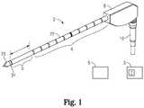
- FIG. 1is a right, perspective view of an ablation probe having a sensing configuration according to an embodiment of the present disclosure
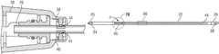
- FIG. 2is a partial, left side view of the ablation probe depicted in FIG. 1 with a left side portion of a housing being removed to illustrate a portion of a sensor assembly according to an embodiment of the present disclosure
- FIG. 3is a left, perspective view illustrating a pair of sensor contacts of the sensor assembly depicted in FIG. 2 ;
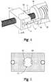
- FIG. 4is a left, perspective view illustrating the sensor assembly coupled to an end cap of the ablation probe
- FIG. 5is a cut-away view taken along line segment 5 - 5 in FIG. 4 with a shaft of the ablation probe removed;
- FIG. 6is a partial, top elevated view of the ablation probe depicted in FIG. 1 with a top portion of a housing being removed and a top portion of a sensor housing removed to illustrate the sensor contacts in contact with sensor pads disposed on the shaft of the ablation probe;
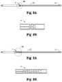
- FIG. 7Ais a side view of the shaft including a sensor configuration according to an embodiment of the instant disclosure.
- FIG. 7Bis an enlarged area of detail depicted in FIG. 7A ;
- FIG. 8Ais a side view of the shaft including a sensor configuration according to another embodiment of the instant disclosure.
- FIG. 8Bis an enlarged area of detail depicted in FIG. 8A ;
- FIG. 9Ais a side view of the shaft including a sensor configuration according to yet another embodiment of the instant disclosure.
- FIG. 9Bis an enlarged area of detail depicted in FIG. 9A ;
- FIG. 10Ais a side view of the shaft including a sensor configuration according to still another embodiment of the instant disclosure.
- FIG. 10Bis an enlarged area of detail depicted in FIG. 10A ;
- FIG. 11is a side view of the shaft including a sensor configuration according to still yet another embodiment of the instant disclosure.
- FIG. 12Ais a side view of the shaft including a sensor configuration according to still yet another embodiment of the instant disclosure.
- FIG. 12Bis an enlarged area of detail depicted in FIG. 12A ;
- FIG. 13Ais a side view of the shaft including a sensor configuration according to still yet another embodiment of the instant disclosure.
- FIG. 13Bis an enlarged area of detail depicted in FIG. 13A ;
- FIG. 14Ais a side view of the shaft including a sensor configuration according to still yet another embodiment of the instant disclosure.
- FIG. 14Bis an enlarged area of detail depicted in FIG. 14A ;
- FIG. 15Ais a side view of the shaft including a sensor configuration according to still yet another embodiment of the instant disclosure.
- FIG. 15Bis an enlarged area of detail depicted in FIG. 15A .
- one or more sensor configurationsare provided on an ablation probe to detect one or more properties that may be associated with target tissue and/or a specific surgical procedure.
- the sensor configuration(s)provides feedback to a clinician or directly to a source of electrosurgical energy, e.g., a microwave generator, to improve overall performance of the ablation device and/or safety to a patient or clinician.
- the sensor configuration(s)includes one or more conductive traces that are deposited on an exterior surface of a shaft of the ablation probe and interrogated at a predetermined frequency to measure one or more electrical properties, e.g., capacitance and/or impedance, that are induced in the conductive traces.
- an ablation probe 2 including a sensor configuration 4is illustrated.
- sensor configuration 4may also be utilized to serve as centimeter depth markings.
- Ablation probe 2is configured to electrosurgically treat tissue utilizing electrosurgical energy having a frequency that ranges from about 2300 MHz to about 2450 MHz.
- ablation probe 2may be configured to electrosurgically treat tissue utilizing electrosurgical energy having a frequency that is less than 2300 MHz (e.g., 915 MHz) and greater than 2450 MHz.
- ablation probe 2utilizes microwave energy that is provided by a microwave energy source, e.g., a generator 3 ( FIG. 1 ), and transmitted at a frequency that ranges from about 2300 MHz to about 2450 MHz to create ablation zones that have a more spherical configuration for a specified range of activation times when compared to conventional ablation probes. Moreover, this higher frequency range allows ablation probe 2 to utilize a radiating section 6 ( FIG.
- radiating section 6provides enhanced focus of the microwave energy transmitted therefrom and into target tissue, which, in turn, allows the microwave energy to penetrate deeper and faster into target tissue, which, in turn, results in a desired tissue effect with shorter activation times of radiating section 6 .
- ablation probe 2includes a housing 8 that is formed from one or more suitable materials, e.g., plastic, metal, metal alloy, ceramic, etc. Housing 8 functions as a handle that may be grasped by a user and is configured to house one or more components of ablation probe 2 .
- a proximal end of housing 8operably couples to a hub 10 ( FIG. 1 ) that couples a cable 12 to ablation probe 2 and one or more leads 14 , 16 ( FIG. 2 ) that are disposed within housing 8 .
- Proximal end 8also couples to in-flow and out-flow tubes 18 , 20 ( FIG. 2 ), respectively, that are coupled to a coolant source 5 ( FIG. 1 ) configured to provide one or more suitable coolants, e.g., saline, to a shaft 22 that serves as a cooling jacket and surrounds radiating section 6 .
- Shaft 22may be formed from any suitable material, e.g., metal, glass fiber, and extends distally from housing 8 .
- shaft 22is formed from glass fiber
- Shaft 22includes a distal end 24 ( FIGS. 1 and 7A ) that includes a ceramic tip 25 ( FIGS. 1 and 7A ) configured to pierce tissue for positioning radiating section 6 adjacent target tissue.
- Shaft 22also includes a proximal end 26 that operably couples to one or more components disposed within housing 8 .
- proximal end 26includes a pair of indents 28 ( FIG. 7A ) that are configured to couple to a pair of corresponding detents (not explicitly shown) that are provided within a hub 30 ( FIGS. 2, 4 and 6 ).
- Hub 30defines in-flow ports 32 and out-flow ports 34 that are configured to couple to corresponding in-flow tubes 18 and out-flow tubes 20 ( FIG. 2 ). In-flow and out-flow ports 32 , 34 , respectively, communicate with one or more lumens (not explicitly shown) that extend through housing 8 and into shaft 22 forming a closed-loop path for providing coolant to radiating section 6 .
- Hub 30includes one or more clocking features (not explicitly shown) that align with one or more corresponding clocking features (not explicitly shown) disposed on an end cap 36 ( FIG. 4 ) that operably couples to a distal end of hub 30 .
- the clocking features on hub 30 and end cap 36are configured to provide passage for leads 14 , 16 so that leads 14 , 16 may be coupled to a pair of sensor contacts 38 , 40 ( FIGS. 2-4 and 6 ) of a sensor assembly 42 ( FIG. 2 ).
- sensor assembly 42is operably disposed within housing 8 and includes sensor contacts 38 , 40 that are configured to contact a corresponding pair of sensor contact pads 44 (see FIGS. 6-7A for example) positioned on shaft 22 .
- one or more electrical parameterse.g., capacitance and/or impedance
- a separate interrogation circuit 7FIG. 1
- interrogation circuit 7may be configured to apply a separate voltage to conductive traces 46 and measure current associated therewith to determine capacitance and/or impedance.
- interrogation circuit 7may be in communication with one or more modules (not shown) of generator 3 and configured to calculate capacitance and/or impedance.
- the interrogation frequency utilizedmay range from about 50 KHz to about 4 MHz.
- sensor contacts 38 , 40are spaced apart a predetermined distance from one another within a sensor housing 48 that is configured to support sensor contacts 38 , 40 (as best seen in FIG. 4 ).
- Proximal ends 50 , 52 of sensor contacts 38 , 40are configured to couple to corresponding leads 14 , 16 that extend within housing 8 ( FIG. 3 ).
- Leads 14 , 16couple to the microwave energy source to provide communication between sensor contacts 38 , 40 and one or more modules (not explicitly shown) of the microwave energy source.
- distal ends 54 , 56are offset from proximal ends 50 , 52 (as best seen in FIG. 3 ) to facilitate contact between sensor contacts 38 , 40 and sensor contact pads 44 .
- distal ends 54 , 56are disposed in oblique relationship with respect to respective proximal ends 50 , 52 and are in substantial horizontal alignment with one another.
- a predetermined gapis provided between the distal ends 54 , 56 and may be determined during the manufacture process. More particularly, the distance of the gap between distal ends 54 , 56 is smaller than an outside diameter of shaft 22 ; this will facilitate contact between distal ends 54 , 56 and sensor contact pads 44 .
- each of distal ends 54 , 56includes a sensor contact surface 58 , 60 ( FIGS. 3 and 5 ) that is configured slide across a corresponding sensor contact pad 44 when shaft 22 is positioned through an aperture 62 that provides passage through sensor housing 48 (see FIGS. 4-5 ).
- sensor contact surfaces 58 , 60may be biased outwardly from distal ends 54 , 56 and movable therein.
- distal ends 54 , 56are flexible and configured to flex when shaft 22 is positioned through aperture 62 .
- notched out portions 64are provided on sensor housing 48 and allow distal ends 54 , 56 to flex or give as shaft 22 is positioned within aperture 62 . The flexibility of distal ends 54 , 56 may be adjusted or varied during the manufacturing process as needed.
- sensor configuration 4(sensor 4 ) is illustrated.
- sensor 4is positioned adjacent radiating section 6 and extends a predetermined length along shaft 22 .
- sensor 4is defined by one or more conductive traces 46 that are formed from a silver ink deposition provided on the exterior surface of shaft 22 .
- a silver ink depositionwas utilized because of its ability to withstand EtO (Ethylene Oxide) sterilization.
- EtOEtO
- Other types of ink depositionsincluding but not limited to gold, copper and nickel may also be utilized.
- One or more methods or processesmay be utilized for depositing the silver ink onto the exterior of surface of shaft 22 . For example, pad printing, laser ablation and direct write are suitable methods for depositing the silver ink onto the exterior surface of shaft 22 .
- the silver ink depositionis utilized to form two or more conductive traces 47 a , 47 b ( FIG. 7B ) that are spaced apart a predetermined distance from one another.
- the distance that conductive traces 47 a , 47 b are spaced apart from one anothermay range from about 0.010 inches to about 0.080 inches.
- the distance that separates conductive traces 47 a , 47 bmay be varied or altered during the silver ink deposition process. Accordingly, in embodiments, the distance that separates conductive traces 47 a , 47 b may be less than 0.050 mm or greater than 0.080 mm.
- each of conductive traces 47 a , 47extends from distal end 24 adjacent radiating section 6 to proximal end 26 adjacent detents 28 and culminates at sensor contact pads 44 that are also formed during the aforementioned silver ink deposition process.
- the distance that separates conductive traces 47 a , 47 and sensor contact pads 44ranges from about 0.050 inches to about 0.100 inches.
- the distance that separates conductive traces 47 a , 47 b and sensor contact pads 44may be varied or altered during the silver ink deposition process. Accordingly, in embodiments, the distance that separates conductive traces 47 a , 47 b and sensor contact pads 44 may be less than 0.001 mm or less than 0.300 mm. The important part of this feature are to have the contact pads spaced far enough apart to ensure electrical isolation from one another, but large enough pad area to ensure contact with the pogo-pin.
- FIGS. 8A-15Billustrate various other configurations of sensor 4 .
- Each of the configurations of sensor 4 shown in FIGS. 8A-15Bmay be formed utilizing the aforementioned materials and silver ink deposition processes.
- Sensors 4 illustrated in FIGS. 7A-15Bmay include any suitable configuration, such as, for example, two horizontal bars ( FIGS. 8A-8B ), two vertical bars ( FIGS. 7A-7B ), multi-band horizontal bars ( FIGS. 9A-9B ), spiral bars ( FIGS. 10A-10B ), or other suitable configuration (see FIGS. 11-15B for example).
- the specific configuration of sensor 4 utilized with ablation probe 2will depend on a manufactures preference, a type of surgical procedure, target tissue (e.g., liver, ling, kidney, etc.), signal to noise ration parameters, etc.
- a shrink wrap 66(shown in phantom in FIG. 7A ), e.g., polyester heat shrink wrap, is provided along shaft 22 to encapsulate conductive traces 47 a , 47 b and sensor contact pads 44 .
- Shrink wrap 66is utilized to maintain the structural integrity of conductive traces 47 a , 47 b and/or sensor contact pads 44 .
- shrink wrap 66is utilized to protect a patient from silver bio-incompatibility. Further, it serves as a nonstick coating to prevent ablated tissue from sticking to sensor 4 , e.g., conductive traces 47 a , 47 b.
- ablation probe 2is configured to function in two modes of operation. Specifically, in a first mode of operation, e.g., a standard or manual ablation mode, sensor 4 may be configured to detect when ablation probe 2 or component associated therewith, e.g., radiating section 6 , has been properly inserted, e.g., fully positioned, within target tissue and may be configured to automatically terminate power to ablation probe 2 if radiating section 6 is inadvertently or purposefully removed from target tissue. In this particular mode of operation, a clinician may position radiating section 6 of ablation probe 2 within target tissue.
- a first mode of operatione.g., a standard or manual ablation mode
- sensor 4may be configured to detect when ablation probe 2 or component associated therewith, e.g., radiating section 6 , has been properly inserted, e.g., fully positioned, within target tissue and may be configured to automatically terminate power to ablation probe 2 if radiating section 6 is inadvertently or purposefully removed from target tissue
- One or more modules associated with generator 3may be coupled to conductive traces 47 a , 47 b and configured to send an interrogatory pulse thereto to determine if radiating section 6 has been properly inserted into target tissue, e.g., liver tissue. If the module(s) detects a predetermined capacitance and/or impedance induced within conductive traces 47 a , 47 b , a clinician may initiate the transmission of microwave energy to radiating section 6 . It has been shown through empirical testing that suitable interrogation frequencies for capacitance may range from about 200 KHz to about 600 KHz. Moreover, it has been shown through empirical testing that suitable interrogation frequencies for impedance may range from about 40 KHz to about 600 KHz. In manual mode of operation, generator 3 automatically shuts off if radiating section 6 is inadvertently or purposefully removed from target tissue during transmission of microwave energy therefrom.
- the generatormay be configured to automatically initiate and terminate power to ablation probe 2 based on proper insertion of ablation probe 2 .
- a clinicianmay position radiating 6 of section ablation probe 2 within target tissue.
- One or more modules associated with generator 3may be coupled to conductive traces 47 a , 47 b and configured to send an interrogatory pulse thereto to determine if radiating section 6 has been properly inserted into target tissue, e.g., liver tissue.
- generator 3In resection mode, if the module(s) detects a predetermined capacitance and/or impedance induced within conductive traces 47 a , 47 b , generator 3 automatically initiates the transmission of microwave energy to radiating section 6 . Generator 3 automatically shuts off if radiating section 6 is inadvertently or purposefully removed from target tissue during transmission of microwave energy therefrom. This particular mode of operation allows a clinician to rapidly change positions down a resection line without having to manually turn the generator on and off.
- sensor 4may be utilized to determine other parameters that may associated with ablation probe 2 and/or a surgical procedure.
- sensor 4may be configured to detect tissue type, progression of a microwave ablation procedure, completion of a microwave ablation procedure, etc.
- sensor 4may be utilized to detect the presence of a cooling fluid that is being circulated through ablation probe 2 and/or component associated therewith, e.g., shaft 22 ; this could mitigate circulation errors, e.g., a clinician forgets to circulate fluid to radiating section 6 . As can be appreciated, this may increase the operative shelf life of radiating section 6 and/or ablation probe 2 .
Landscapes
- Physics & Mathematics (AREA)
- Engineering & Computer Science (AREA)
- Health & Medical Sciences (AREA)
- Electromagnetism (AREA)
- Surgery (AREA)
- Life Sciences & Earth Sciences (AREA)
- Optics & Photonics (AREA)
- Mechanical Engineering (AREA)
- Plasma & Fusion (AREA)
- Medical Informatics (AREA)
- Heart & Thoracic Surgery (AREA)
- Molecular Biology (AREA)
- Animal Behavior & Ethology (AREA)
- General Health & Medical Sciences (AREA)
- Public Health (AREA)
- Veterinary Medicine (AREA)
- Biomedical Technology (AREA)
- Otolaryngology (AREA)
- Nuclear Medicine, Radiotherapy & Molecular Imaging (AREA)
- Surgical Instruments (AREA)
Abstract
Description
Claims (17)
Priority Applications (1)
| Application Number | Priority Date | Filing Date | Title |
|---|---|---|---|
| US15/905,065US10828102B2 (en) | 2012-12-17 | 2018-02-26 | Ablation probe with tissue sensing configuration |
Applications Claiming Priority (3)
| Application Number | Priority Date | Filing Date | Title |
|---|---|---|---|
| US201261738021P | 2012-12-17 | 2012-12-17 | |
| US14/064,472US9901399B2 (en) | 2012-12-17 | 2013-10-28 | Ablation probe with tissue sensing configuration |
| US15/905,065US10828102B2 (en) | 2012-12-17 | 2018-02-26 | Ablation probe with tissue sensing configuration |
Related Parent Applications (1)
| Application Number | Title | Priority Date | Filing Date |
|---|---|---|---|
| US14/064,472DivisionUS9901399B2 (en) | 2012-12-17 | 2013-10-28 | Ablation probe with tissue sensing configuration |
Publications (2)
| Publication Number | Publication Date |
|---|---|
| US20180235696A1 US20180235696A1 (en) | 2018-08-23 |
| US10828102B2true US10828102B2 (en) | 2020-11-10 |
Family
ID=50931759
Family Applications (2)
| Application Number | Title | Priority Date | Filing Date |
|---|---|---|---|
| US14/064,472Active2035-01-16US9901399B2 (en) | 2012-12-17 | 2013-10-28 | Ablation probe with tissue sensing configuration |
| US15/905,065Active2034-04-07US10828102B2 (en) | 2012-12-17 | 2018-02-26 | Ablation probe with tissue sensing configuration |
Family Applications Before (1)
| Application Number | Title | Priority Date | Filing Date |
|---|---|---|---|
| US14/064,472Active2035-01-16US9901399B2 (en) | 2012-12-17 | 2013-10-28 | Ablation probe with tissue sensing configuration |
Country Status (1)
| Country | Link |
|---|---|
| US (2) | US9901399B2 (en) |
Families Citing this family (4)
| Publication number | Priority date | Publication date | Assignee | Title |
|---|---|---|---|---|
| US8568401B2 (en) | 2009-10-27 | 2013-10-29 | Covidien Lp | System for monitoring ablation size |
| US8430871B2 (en) | 2009-10-28 | 2013-04-30 | Covidien Lp | System and method for monitoring ablation size |
| US9901399B2 (en) | 2012-12-17 | 2018-02-27 | Covidien Lp | Ablation probe with tissue sensing configuration |
| GB2559332B8 (en)* | 2017-01-27 | 2020-09-30 | Gyrus Medical Ltd | Microwave ablation applicators |
Citations (192)
| Publication number | Priority date | Publication date | Assignee | Title |
|---|---|---|---|---|
| SU166452A1 (en) | В. А. Костров , Л. В. Смирнов | STOMATOLOGICAL DIATHERMOKOAGULATOR | ||
| DE390937C (en) | 1922-10-13 | 1924-03-03 | Adolf Erb | Device for internal heating of furnace furnaces for hardening, tempering, annealing, quenching and melting |
| DE1099658B (en) | 1959-04-29 | 1961-02-16 | Siemens Reiniger Werke Ag | Automatic switch-on device for high-frequency surgical devices |
| FR1275415A (en) | 1960-09-26 | 1961-11-10 | Device for detecting disturbances for electrical installations, in particular electrosurgery | |
| DE1139927B (en) | 1961-01-03 | 1962-11-22 | Friedrich Laber | High-frequency surgical device |
| DE1149832B (en) | 1961-02-25 | 1963-06-06 | Siemens Reiniger Werke Ag | High frequency surgical apparatus |
| FR1347865A (en) | 1962-11-22 | 1964-01-04 | Improvements to diathermo-coagulation devices | |
| DE1439302A1 (en) | 1963-10-26 | 1969-01-23 | Siemens Ag | High-frequency surgical device |
| SU401367A1 (en) | 1971-10-05 | 1973-10-12 | Тернопольский государственный медицинский институт | BIAKTIVNYE ELECTRO SURGICAL INSTRUMENT |
| FR2235669A1 (en) | 1973-07-07 | 1975-01-31 | Lunacek Boris | Gynaecological sterilisation instrument - has hollow electrode protruding from the end of a curved ended tube |
| DE2439587A1 (en) | 1973-08-23 | 1975-02-27 | Matburn Holdings Ltd | ELECTROSURGICAL DEVICE |
| DE2455174A1 (en) | 1973-11-21 | 1975-05-22 | Termiflex Corp | INPUT / OUTPUT DEVICE FOR DATA EXCHANGE WITH DATA PROCESSING DEVICES |
| DE2407559A1 (en) | 1974-02-16 | 1975-08-28 | Dornier System Gmbh | Tissue heat treatment probe - has water cooling system which ensures heat development only in treated tissues |
| DE2415263A1 (en) | 1974-03-29 | 1975-10-02 | Aesculap Werke Ag | Surgical H.F. coagulation probe has electrode tongs - with exposed ends of insulated conductors forming tong-jaws |
| DE2429021A1 (en) | 1974-06-18 | 1976-01-08 | Erbe Elektromedizin | Remote control for HF surgical instruments - uses cable with two conductors at most |
| FR2276027A1 (en) | 1974-06-25 | 1976-01-23 | Medical Plastics Inc | Plate electrode with connector - is clamped between connector jaws held by releasable locking device |
| DE2460481A1 (en) | 1974-12-20 | 1976-06-24 | Delma Elektro Med App | Electrode grip for remote HF surgical instrument switching - has shaped insulated piece with contact ring of sterilizable (silicon) rubber |
| DE2602517A1 (en) | 1975-01-23 | 1976-07-29 | Dentsply Int Inc | ELECTROSURGICAL DEVICE |
| DE2504280A1 (en) | 1975-02-01 | 1976-08-05 | Hans Heinrich Prof Dr Meinke | DEVICE FOR ELECTRIC TISSUE CUTTING IN SURGERY |
| FR2313708A1 (en) | 1975-06-02 | 1976-12-31 | Sybron Corp | Electro surgical instrument impulse control circuit - has potentiometer between patient electrodes and threshold switch for excessive voltage |
| DE2627679A1 (en) | 1975-06-26 | 1977-01-13 | Marcel Lamidey | HEMATISTIC HIGH FREQUENCY EXTRACTOR FORCEPS |
| DE2540968A1 (en) | 1975-09-13 | 1977-03-17 | Erbe Elektromedizin | Circuit for bipolar coagulation tweezers - permits preparation of tissues prior to coagulation |
| DE2820908A1 (en) | 1977-05-16 | 1978-11-23 | Joseph Skovajsa | DEVICE FOR THE LOCAL TREATMENT OF A PATIENT IN PARTICULAR FOR ACUPUNCTURE OR AURICULAR THERAPY |
| DE2803275A1 (en) | 1978-01-26 | 1979-08-02 | Aesculap Werke Ag | HF surgical appts. with active treatment and patient electrodes - has sensor switching generator to small voltage when hand-operated switch is closed |
| DE2823291A1 (en) | 1978-05-27 | 1979-11-29 | Rainer Ing Grad Koch | Coagulation instrument automatic HF switching circuit - has first lead to potentiometer and second to transistor base |
| JPS55106B1 (en) | 1975-04-03 | 1980-01-05 | ||
| SU727201A2 (en) | 1977-11-02 | 1980-04-15 | Киевский Научно-Исследовательский Институт Нейрохирургии | Electric surgical apparatus |
| DE2946728A1 (en) | 1979-11-20 | 1981-05-27 | Erbe Elektromedizin GmbH & Co KG, 7400 Tübingen | HF surgical appts. for use with endoscope - provides cutting or coagulation current at preset intervals and of selected duration |
| US4291708A (en) | 1977-11-02 | 1981-09-29 | Yeda Research & Development Co. Ltd. | Apparatus and method for detection of tumors in tissue |
| USD263020S (en) | 1980-01-22 | 1982-02-16 | Rau Iii David M | Retractable knife |
| DE3143421A1 (en) | 1980-11-04 | 1982-05-27 | The Agency of Industrial Science and Technology, Tokyo | Laser scalpel |
| DE3045996A1 (en) | 1980-12-05 | 1982-07-08 | Medic Eschmann Handelsgesellschaft für medizinische Instrumente mbH, 2000 Hamburg | Electro-surgical scalpel instrument - has power supply remotely controlled by surgeon |
| FR2502935A1 (en) | 1981-03-31 | 1982-10-08 | Dolley Roger | Diathermic knife for coagulating tissues - has monitoring current added to HF coagulating current in order to control end of operation as function or resistance of coagulating tissues |
| USD266842S (en) | 1980-06-27 | 1982-11-09 | Villers Mark W | Phonograph record spacer |
| DE3120102A1 (en) | 1981-05-20 | 1982-12-09 | F.L. Fischer GmbH & Co, 7800 Freiburg | ARRANGEMENT FOR HIGH-FREQUENCY COAGULATION OF EGG WHITE FOR SURGICAL PURPOSES |
| FR2517953A1 (en) | 1981-12-10 | 1983-06-17 | Alvar Electronic | Diaphanometer for optical examination of breast tissue structure - measures tissue transparency using two plates and optical fibre bundle cooperating with photoelectric cells |
| USD278306S (en) | 1980-06-30 | 1985-04-09 | Mcintosh Lois A | Microwave oven rack |
| FR2573301A1 (en) | 1984-11-16 | 1986-05-23 | Lamidey Gilles | Surgical forceps and its control and monitoring apparatus |
| DE3510586A1 (en) | 1985-03-23 | 1986-10-02 | Erbe Elektromedizin GmbH, 7400 Tübingen | Control device for a high-frequency surgical instrument |
| DE3604823A1 (en) | 1986-02-15 | 1987-08-27 | Flachenecker Gerhard | HIGH FREQUENCY GENERATOR WITH AUTOMATIC PERFORMANCE CONTROL FOR HIGH FREQUENCY SURGERY |
| EP0246350A1 (en) | 1986-05-23 | 1987-11-25 | Erbe Elektromedizin GmbH. | Coagulation electrode |
| USD295894S (en) | 1985-09-26 | 1988-05-24 | Acme United Corporation | Disposable surgical scissors |
| USD295893S (en) | 1985-09-25 | 1988-05-24 | Acme United Corporation | Disposable surgical clamp |
| DE3711511C1 (en) | 1987-04-04 | 1988-06-30 | Hartmann & Braun Ag | Method for determining gas concentrations in a gas mixture and sensor for measuring thermal conductivity |
| DE3712328A1 (en) | 1987-04-11 | 1988-10-27 | Messerschmitt Boelkow Blohm | DEVICE FOR INFRARED RADIATION SHIELDING |
| DE3904558A1 (en) | 1989-02-15 | 1990-08-23 | Flachenecker Gerhard | Radio-frequency generator with automatic power control for radio-frequency surgery |
| DE3942998A1 (en) | 1989-12-27 | 1991-07-04 | Delma Elektro Med App | Electro-surgical HF instrument for contact coagulation - has monitoring circuit evaluating HF voltage at electrodes and delivering switch=off signal |
| EP0521264A2 (en) | 1991-07-03 | 1993-01-07 | W.L. Gore & Associates GmbH | Antenna device with feed |
| DE4238263A1 (en) | 1991-11-15 | 1993-05-19 | Minnesota Mining & Mfg | Adhesive comprising hydrogel and crosslinked polyvinyl:lactam - is used in electrodes for biomedical application providing low impedance and good mechanical properties when water and/or moisture is absorbed from skin |
| EP0556705A1 (en) | 1992-02-20 | 1993-08-25 | DELMA ELEKTRO-UND MEDIZINISCHE APPARATEBAU GESELLSCHAFT mbH | High frequency surgery device |
| EP0558429A1 (en) | 1992-02-26 | 1993-09-01 | PECHINEY RECHERCHE (Groupement d'Intérêt Economique géré par l'ordonnance no. 67-821 du 23 Septembre 1967) | Method of simultaneous measuring of electrical resistivety and thermal conductivity |
| JPH0540112Y2 (en) | 1987-03-03 | 1993-10-12 | ||
| JPH06343644A (en) | 1993-05-04 | 1994-12-20 | Gyrus Medical Ltd | Surgical peritoneoscope equipment |
| USD354218S (en) | 1992-10-01 | 1995-01-10 | Fiberslab Pty Limited | Spacer for use in concrete construction |
| DE4303882C2 (en) | 1993-02-10 | 1995-02-09 | Kernforschungsz Karlsruhe | Combination instrument for separation and coagulation for minimally invasive surgery |
| EP0648515A1 (en) | 1993-10-15 | 1995-04-19 | SADIS BRUKER SPECTROSPIN, SOCIETE ANONYME DE DIFFUSION DE L'INSTRUMENTATION SCIENTIFIQUE BRUKER SPECTROSPIN (S.A. à Direct.) | Antenna for microwave heating of tissue and catheter with one or more antennas |
| DE4339049A1 (en) | 1993-11-16 | 1995-05-18 | Erbe Elektromedizin | Surgical system and instruments configuration device |
| US5423810A (en) | 1992-02-27 | 1995-06-13 | G2 Design Limited | Cauterising apparatus |
| JPH07265328A (en) | 1993-11-01 | 1995-10-17 | Gyrus Medical Ltd | Electrode assembly for electric surgery device and electric surgery device using it |
| JPH0856955A (en) | 1994-06-29 | 1996-03-05 | Gyrus Medical Ltd | Electric surgical apparatus |
| US5500012A (en) | 1992-07-15 | 1996-03-19 | Angeion Corporation | Ablation catheter system |
| JPH08252263A (en) | 1994-12-21 | 1996-10-01 | Gyrus Medical Ltd | Electronic surgical incision instrument and electronic surgical incision device using the same |
| DE29616210U1 (en) | 1996-09-18 | 1996-11-14 | Olympus Winter & Ibe Gmbh, 22045 Hamburg | Handle for surgical instruments |
| JPH09492A (en) | 1995-06-21 | 1997-01-07 | Olympus Optical Co Ltd | Treatment tool inserting and detaching device for endoscope |
| JPH0910223A (en) | 1995-06-23 | 1997-01-14 | Gyrus Medical Ltd | Generator and system for electric operation |
| DE19608716C1 (en) | 1996-03-06 | 1997-04-17 | Aesculap Ag | Bipolar surgical holding instrument |
| EP0836868A2 (en) | 1996-10-18 | 1998-04-22 | Gebr. Berchtold GmbH & Co. | High frequency surgical apparatus and method for operating same |
| DE19751106A1 (en) | 1996-11-27 | 1998-05-28 | Eastman Kodak Co | Laser printer with array of laser diodes |
| US5810804A (en) | 1995-08-15 | 1998-09-22 | Rita Medical Systems | Multiple antenna ablation apparatus and method with cooling element |
| DE19717411A1 (en) | 1997-04-25 | 1998-11-05 | Aesculap Ag & Co Kg | Monitoring of thermal loading of patient tissue in contact region of neutral electrode of HF treatment unit |
| EP0882955A1 (en) | 1997-06-06 | 1998-12-09 | Endress + Hauser GmbH + Co. | Level measuring apparatus using microwaves |
| DE19751108A1 (en) | 1997-11-18 | 1999-05-20 | Beger Frank Michael Dipl Desig | Electrosurgical operation tool, especially for diathermy |
| DE19801173C1 (en) | 1998-01-15 | 1999-07-15 | Kendall Med Erzeugnisse Gmbh | Clamp connector for film electrodes |
| JPH11244298A (en) | 1997-12-19 | 1999-09-14 | Gyrus Medical Ltd | Electric surgical instrument |
| USD424694S (en) | 1998-10-23 | 2000-05-09 | Sherwood Services Ag | Forceps |
| US6059780A (en) | 1995-08-15 | 2000-05-09 | Rita Medical Systems, Inc. | Multiple antenna ablation apparatus and method with cooling element |
| USD424693S (en) | 1999-04-08 | 2000-05-09 | Pruter Rick L | Needle guide for attachment to an ultrasound transducer probe |
| USD425201S (en) | 1998-10-23 | 2000-05-16 | Sherwood Services Ag | Disposable electrode assembly |
| DE19848540A1 (en) | 1998-10-21 | 2000-05-25 | Reinhard Kalfhaus | Circuit layout and method for operating a single- or multiphase current inverter connects an AC voltage output to a primary winding and current and a working resistance to a transformer's secondary winding and current. |
| WO2000036985A2 (en) | 1998-12-18 | 2000-06-29 | Celon Ag Medical Instruments | Electrode assembly for a surgical instrument provided for carrying out an electrothermal coagulation of tissue |
| US6123702A (en) | 1998-09-10 | 2000-09-26 | Scimed Life Systems, Inc. | Systems and methods for controlling power in an electrosurgical probe |
| JP2000342599A (en) | 1999-05-21 | 2000-12-12 | Gyrus Medical Ltd | Generator for electrosurgical operation, electrosurgical operation system, method for operating this system and method for performing amputation and resection of tissue by electrosurgical operation |
| JP2000350732A (en) | 1999-05-21 | 2000-12-19 | Gyrus Medical Ltd | Electrosurgical system, generator for electrosurgery, and method for cutting or excising tissue by electrosurgery |
| JP2001003776A (en) | 1999-06-22 | 2001-01-09 | Mitsubishi Electric Corp | Automatic transmission control device |
| JP2001029356A (en) | 1999-06-11 | 2001-02-06 | Gyrus Medical Ltd | Electric and surgical signal generator |
| JP2001037775A (en) | 1999-07-26 | 2001-02-13 | Olympus Optical Co Ltd | Treatment device |
| JP2001128990A (en) | 1999-05-28 | 2001-05-15 | Gyrus Medical Ltd | Electro surgical instrument and electrosurgical tool converter |
| JP2001231870A (en) | 2000-02-23 | 2001-08-28 | Olympus Optical Co Ltd | Moisturizing treatment apparatus |
| WO2001074252A2 (en) | 2000-03-31 | 2001-10-11 | Rita Medical Systems Inc. | Tissue biopsy and treatment apparatus and method |
| USD449886S1 (en) | 1998-10-23 | 2001-10-30 | Sherwood Services Ag | Forceps with disposable electrode |
| EP1159926A2 (en) | 2000-06-03 | 2001-12-05 | Aesculap Ag | Scissor- or forceps-like surgical instrument |
| USD457958S1 (en) | 2001-04-06 | 2002-05-28 | Sherwood Services Ag | Vessel sealer and divider |
| USD457959S1 (en) | 2001-04-06 | 2002-05-28 | Sherwood Services Ag | Vessel sealer |
| US20020077627A1 (en) | 2000-07-25 | 2002-06-20 | Johnson Theodore C. | Method for detecting and treating tumors using localized impedance measurement |
| US20020120261A1 (en) | 2001-02-28 | 2002-08-29 | Morris David L. | Tissue surface treatment apparatus and method |
| US6494882B1 (en) | 2000-07-25 | 2002-12-17 | Verimetra, Inc. | Cutting instrument having integrated sensors |
| CN1103807C (en) | 1997-12-18 | 2003-03-26 | 英菲诺姆美国公司 | Anti-wear agents for lubricating compositions |
| US6569162B2 (en) | 2001-03-29 | 2003-05-27 | Ding Sheng He | Passively self-cooled electrode design for ablation catheters |
| DE10224154A1 (en) | 2002-05-27 | 2003-12-18 | Celon Ag Medical Instruments | Application device for electrosurgical device for body tissue removal via of HF current has electrode subset selected from active electrode set in dependence on measured impedance of body tissue |
| USD487039S1 (en) | 2002-11-27 | 2004-02-24 | Robert Bosch Corporation | Spacer |
| US6702810B2 (en) | 2000-03-06 | 2004-03-09 | Tissuelink Medical Inc. | Fluid delivery system and controller for electrosurgical devices |
| US6706040B2 (en) | 2001-11-23 | 2004-03-16 | Medlennium Technologies, Inc. | Invasive therapeutic probe |
| US20040097805A1 (en) | 2002-11-19 | 2004-05-20 | Laurent Verard | Navigation system for cardiac therapies |
| DE10310765A1 (en) | 2003-03-12 | 2004-09-30 | Dornier Medtech Systems Gmbh | Medical thermotherapy instrument, e.g. for treatment of benign prostatic hypertrophy (BPH), has an antenna that can be set to radiate at least two different frequency microwave signals |
| USD496997S1 (en) | 2003-05-15 | 2004-10-05 | Sherwood Services Ag | Vessel sealer and divider |
| USD499181S1 (en) | 2003-05-15 | 2004-11-30 | Sherwood Services Ag | Handle for a vessel sealer and divider |
| DE10328514B3 (en) | 2003-06-20 | 2005-03-03 | Aesculap Ag & Co. Kg | Endoscopic surgical scissor instrument has internal pushrod terminating at distal end in transverse cylindrical head |
| FR2862813A1 (en) | 2003-11-20 | 2005-05-27 | Pellenc Sa | METHOD FOR BALANCED LOADING OF LITHIUM-ION OR POLYMER LITHIUM BATTERY |
| FR2864439A1 (en) | 2003-12-30 | 2005-07-01 | Image Guided Therapy | Tumor treating device for use by surgeon, has generator applying voltage to each of active electrodes in manner independent from other electrodes and having sinusoidal voltage generation unit adjusting amplitude and phase of voltage |
| DE102004022206A1 (en) | 2004-05-04 | 2005-12-01 | Bundesrepublik Deutschland, vertr. d. d. Bundesministerium für Wirtschaft und Arbeit, dieses vertr. d. d. Präsidenten der Physikalisch-Technischen Bundesanstalt | Sensor for measuring thermal conductivity comprises a strip composed of two parallel sections, and two outer heating strips |
| DE202005015147U1 (en) | 2005-09-26 | 2006-02-09 | Health & Life Co., Ltd., Chung-Ho | Biosensor test strip with identifying function for biological measuring instruments has functioning electrode and counter electrode, identification zones with coating of electrically conductive material and reaction zone |
| USD525361S1 (en) | 2004-10-06 | 2006-07-18 | Sherwood Services Ag | Hemostat style elongated dissecting and dividing instrument |
| US20060163744A1 (en) | 2005-01-14 | 2006-07-27 | Cabot Corporation | Printable electrical conductors |
| US7108696B2 (en) | 2001-01-11 | 2006-09-19 | Rita Medical Systems, Inc. | Bone-treatment instrument and method |
| WO2006105121A2 (en) | 2005-03-28 | 2006-10-05 | Minnow Medical, Llc | Intraluminal electrical tissue characterization and tuned rf energy for selective treatment of atheroma and other target tissues |
| USD531311S1 (en) | 2004-10-06 | 2006-10-31 | Sherwood Services Ag | Pistol grip style elongated dissecting and dividing instrument |
| USD533942S1 (en) | 2004-06-30 | 2006-12-19 | Sherwood Services Ag | Open vessel sealer with mechanical cutter |
| USD535027S1 (en) | 2004-10-06 | 2007-01-09 | Sherwood Services Ag | Low profile vessel sealing and cutting mechanism |
| US7160296B2 (en) | 2001-05-10 | 2007-01-09 | Rita Medical Systems, Inc. | Tissue ablation apparatus and method |
| USD541418S1 (en) | 2004-10-06 | 2007-04-24 | Sherwood Services Ag | Lung sealing device |
| USD541938S1 (en) | 2004-04-09 | 2007-05-01 | Sherwood Services Ag | Open vessel sealer with mechanical cutter |
| EP1810628A1 (en) | 2006-01-24 | 2007-07-25 | Sherwood Services AG | System and method for tissue sealing |
| US20070173806A1 (en) | 2006-01-24 | 2007-07-26 | Sherwood Services Ag | System and method for closed loop monitoring of monopolar electrosurgical apparatus |
| US20070203551A1 (en) | 2005-07-01 | 2007-08-30 | Microsulis Limited | Radiation applicator and method of radiating tissue |
| WO2007100559A2 (en) | 2006-02-23 | 2007-09-07 | Magnetecs, Inc. | Apparatus for magnetically deployable catheter with mosfet sensor and method for mapping and ablation |
| KR20070093068A (en) | 2004-12-22 | 2007-09-17 | 텔레폰악티에볼라겟엘엠에릭슨(펍) | Method and apparatus for providing communication group information to a client |
| USD564662S1 (en) | 2004-10-13 | 2008-03-18 | Sherwood Services Ag | Hourglass-shaped knife for electrosurgical forceps |
| US7344533B2 (en) | 2001-09-28 | 2008-03-18 | Angiodynamics, Inc. | Impedance controlled tissue ablation apparatus and method |
| US20080125775A1 (en) | 2001-02-28 | 2008-05-29 | Morris David L | Hemostasis and/or coagulation of tissue |
| JP2008142467A (en) | 2006-12-13 | 2008-06-26 | Murata Mfg Co Ltd | Coaxial probe |
| USD576932S1 (en) | 2005-03-01 | 2008-09-16 | Robert Bosch Gmbh | Spacer |
| USD594737S1 (en) | 2008-10-28 | 2009-06-23 | Mmi Management Services Lp | Rebar chair |
| USD594736S1 (en) | 2008-08-13 | 2009-06-23 | Saint-Gobain Ceramics & Plastics, Inc. | Spacer support |
| US20090187180A1 (en) | 2008-01-23 | 2009-07-23 | Vivant Medical, Inc. | Choked Dielectric Loaded Tip Dipole Microwave Antenna |
| US20090240273A1 (en) | 2008-03-24 | 2009-09-24 | Tyco Healthcare Group Lp | Surgical Introducer with Indicators |
| US20090306655A1 (en)* | 2008-06-09 | 2009-12-10 | Stangenes Todd R | Catheter assembly with front-loaded tip and multi-contact connector |
| USD606203S1 (en) | 2008-07-04 | 2009-12-15 | Cambridge Temperature Concepts, Ltd. | Hand-held device |
| KR20100014406A (en) | 2007-02-13 | 2010-02-10 | 스카이프 리미티드 | Messaging system and method |
| WO2010035831A1 (en) | 2008-09-29 | 2010-04-01 | 京セラ株式会社 | Cutting insert, cutting tool, and cutting method using cutting insert and cutting tool |
| USD613412S1 (en) | 2009-08-06 | 2010-04-06 | Vivant Medical, Inc. | Vented microwave spacer |
| US20100114086A1 (en) | 2007-04-19 | 2010-05-06 | Deem Mark E | Methods, devices, and systems for non-invasive delivery of microwave therapy |
| DE102009015699A1 (en) | 2008-10-30 | 2010-05-06 | Rohde & Schwarz Gmbh & Co. Kg | Broadband antenna |
| US20100217253A1 (en) | 2007-06-15 | 2010-08-26 | Primaeva Medical, Inc. | Devices and methods for percutaneous energy delivery |
| USD634010S1 (en) | 2009-08-05 | 2011-03-08 | Vivant Medical, Inc. | Medical device indicator guide |
| US20110092972A1 (en) | 2009-10-21 | 2011-04-21 | Tyco Healthcare Group Lp | Methods for Ultrasonic Tissue Sensing and Feedback |
| US20110118724A1 (en) | 2009-11-17 | 2011-05-19 | Bsd Medical Corporation | Microwave coagulation applicator and system with fluid injection |
| US20110152853A1 (en) | 2009-12-18 | 2011-06-23 | Prakash Manley | Microwave Ablation System With Dielectric Temperature Probe |
| US20110184403A1 (en) | 2010-01-25 | 2011-07-28 | Vivant Medical, Inc. | System and Method for Monitoring Ablation Size |
| US20110190754A1 (en) | 2010-01-29 | 2011-08-04 | Steven Kim | Apparatus and Methods of Use for Treating Blood Vessels |
| US20110208184A1 (en) | 2010-02-19 | 2011-08-25 | Vivant Medical, Inc. | Bipolar Electrode Probe For Ablation Monitoring |
| US20110223812A1 (en)* | 2009-06-05 | 2011-09-15 | Apple Inc. | Audio plug with core structural member |
| US20120116388A1 (en) | 2010-11-05 | 2012-05-10 | Houser Kevin L | Surgical instrument with modular shaft and end effector |
| KR20120055063A (en) | 2010-11-23 | 2012-05-31 | 김상훈 | Sand sterilization method of children's sand playground |
| US8257349B2 (en) | 2008-03-28 | 2012-09-04 | Tyco Healthcare Group Lp | Electrosurgical apparatus with predictive RF source control |
| USD681810S1 (en) | 2012-03-05 | 2013-05-07 | Covidien Lp | Ergonomic handle for ablation device |
| US20130317495A1 (en) | 2007-06-28 | 2013-11-28 | Covidien Lp | Broadband microwave applicator |
| US20130324911A1 (en) | 2012-05-31 | 2013-12-05 | Covidien Lp | Ablation device with drug delivery component |
| US20130324910A1 (en) | 2012-05-31 | 2013-12-05 | Covidien Lp | Ablation device with drug delivery component and biopsy tissue-sampling component |
| US20130345552A1 (en) | 2012-06-26 | 2013-12-26 | Covidien Lp | Methods and systems for enhancing ultrasonic visibility of energy-delivery devices within tissue |
| US20130345541A1 (en) | 2012-06-26 | 2013-12-26 | Covidien Lp | Electrosurgical device incorporating a photo-acoustic system for interrogating/imaging tissue |
| US20140018793A1 (en) | 2012-07-12 | 2014-01-16 | Covidien Lp | Heat-distribution indicators, thermal zone indicators, electrosurgical systems including same and methods of directing energy to tissue using same |
| US8655454B2 (en) | 2007-11-27 | 2014-02-18 | Covidien Lp | Targeted cooling of deployable microwave antenna with cooling chamber |
| US8795268B2 (en) | 2008-08-28 | 2014-08-05 | Covidien Lp | Microwave antenna |
| US8852180B2 (en) | 2009-10-28 | 2014-10-07 | Covidien Lp | System and method for monitoring ablation size |
| US8906008B2 (en) | 2012-05-22 | 2014-12-09 | Covidien Lp | Electrosurgical instrument |
| US8920410B2 (en) | 2012-05-04 | 2014-12-30 | Covidien Lp | Peripheral switching device for microwave energy platforms |
| US8945113B2 (en) | 2012-04-05 | 2015-02-03 | Covidien Lp | Electrosurgical tissue ablation systems capable of detecting excessive bending of a probe and alerting a user |
| US8968300B2 (en) | 2009-08-05 | 2015-03-03 | Covidien Lp | Electrosurgical devices having dielectric loaded coaxial aperture with distally positioned resonant structure |
| US8968290B2 (en) | 2012-03-14 | 2015-03-03 | Covidien Lp | Microwave ablation generator control system |
| US9017328B2 (en) | 2008-01-29 | 2015-04-28 | Covidien Lp | Polyp encapsulation system and method |
| US9066681B2 (en) | 2012-06-26 | 2015-06-30 | Covidien Lp | Methods and systems for enhancing ultrasonic visibility of energy-delivery devices within tissue |
| US9168178B2 (en) | 2012-05-22 | 2015-10-27 | Covidien Lp | Energy-delivery system and method for controlling blood loss from wounds |
| US9192308B2 (en) | 2012-03-27 | 2015-11-24 | Covidien Lp | Microwave-shielded tissue sensor probe |
| US9192439B2 (en) | 2012-06-29 | 2015-11-24 | Covidien Lp | Method of manufacturing a surgical instrument |
| US9192440B2 (en) | 2010-02-05 | 2015-11-24 | Covidien Lp | Electrosurgical devices with choke shorted to biological tissue |
| US9192426B2 (en) | 2012-06-26 | 2015-11-24 | Covidien Lp | Ablation device having an expandable chamber for anchoring the ablation device to tissue |
| US9332959B2 (en) | 2012-06-26 | 2016-05-10 | Covidien Lp | Methods and systems for enhancing ultrasonic visibility of energy-delivery devices within tissue |
| US9358067B2 (en) | 2010-02-26 | 2016-06-07 | Covidien Lp | Tissue ablation system with internal and external radiation sources |
| US9364278B2 (en) | 2012-04-30 | 2016-06-14 | Covidien Lp | Limited reuse ablation needles and ablation devices for use therewith |
| US9370392B2 (en) | 2012-10-02 | 2016-06-21 | Covidien Lp | Heat-sensitive optical probes |
| US9375196B2 (en) | 2012-07-12 | 2016-06-28 | Covidien Lp | System and method for detecting critical structures using ultrasound |
| US9396645B2 (en) | 2013-07-16 | 2016-07-19 | Rockwilli RMR LLC | Systems and methods for automated personal emergency responses |
| US9439712B2 (en) | 2012-07-12 | 2016-09-13 | Covidien Lp | Heat-distribution indicators, thermal zone indicators, electrosurgical systems including same and methods of directing energy to tissue using same |
| US9504524B2 (en) | 2009-05-19 | 2016-11-29 | Covidien Lp | Tissue impedance measurement using a secondary frequency |
| US9522033B2 (en) | 2012-10-02 | 2016-12-20 | Covidien Lp | Devices and methods for optical detection of tissue contact |
| US9649146B2 (en) | 2012-10-02 | 2017-05-16 | Covidien Lp | Electro-thermal device |
| US9668802B2 (en) | 2012-10-02 | 2017-06-06 | Covidien Lp | Devices and methods for optical detection of tissue contact |
| US9814844B2 (en) | 2013-08-27 | 2017-11-14 | Covidien Lp | Drug-delivery cannula assembly |
| US9833286B2 (en) | 2009-05-06 | 2017-12-05 | Covidien Lp | Power-stage antenna integrated system with high-strength shaft |
| US9901399B2 (en) | 2012-12-17 | 2018-02-27 | Covidien Lp | Ablation probe with tissue sensing configuration |
| US9901398B2 (en) | 2012-06-29 | 2018-02-27 | Covidien Lp | Microwave antenna probes |
| JP2020018944A (en) | 2019-11-12 | 2020-02-06 | 株式会社ユニバーサルエンターテインメント | Game machine |
Family Cites Families (5)
| Publication number | Priority date | Publication date | Assignee | Title |
|---|---|---|---|---|
| DE8712328U1 (en) | 1987-09-11 | 1988-02-18 | Jakoubek, Franz, 7201 Emmingen-Liptingen | Endoscopy forceps |
| JP2806511B2 (en) | 1990-07-31 | 1998-09-30 | 松下電工株式会社 | Manufacturing method of sintered alloy |
| JP2951418B2 (en) | 1991-02-08 | 1999-09-20 | トキコ株式会社 | Sample liquid component analyzer |
| CN1079269C (en) | 1993-11-17 | 2002-02-20 | 刘中一 | Multi-frequency micro-wave therapeutic instrument |
| GB9912625D0 (en) | 1999-05-28 | 1999-07-28 | Gyrus Medical Ltd | An electrosurgical generator and system |
- 2013
- 2013-10-28USUS14/064,472patent/US9901399B2/enactiveActive
- 2018
- 2018-02-26USUS15/905,065patent/US10828102B2/enactiveActive
Patent Citations (203)
| Publication number | Priority date | Publication date | Assignee | Title |
|---|---|---|---|---|
| SU166452A1 (en) | В. А. Костров , Л. В. Смирнов | STOMATOLOGICAL DIATHERMOKOAGULATOR | ||
| DE390937C (en) | 1922-10-13 | 1924-03-03 | Adolf Erb | Device for internal heating of furnace furnaces for hardening, tempering, annealing, quenching and melting |
| DE1099658B (en) | 1959-04-29 | 1961-02-16 | Siemens Reiniger Werke Ag | Automatic switch-on device for high-frequency surgical devices |
| FR1275415A (en) | 1960-09-26 | 1961-11-10 | Device for detecting disturbances for electrical installations, in particular electrosurgery | |
| DE1139927B (en) | 1961-01-03 | 1962-11-22 | Friedrich Laber | High-frequency surgical device |
| DE1149832B (en) | 1961-02-25 | 1963-06-06 | Siemens Reiniger Werke Ag | High frequency surgical apparatus |
| FR1347865A (en) | 1962-11-22 | 1964-01-04 | Improvements to diathermo-coagulation devices | |
| DE1439302A1 (en) | 1963-10-26 | 1969-01-23 | Siemens Ag | High-frequency surgical device |
| SU401367A1 (en) | 1971-10-05 | 1973-10-12 | Тернопольский государственный медицинский институт | BIAKTIVNYE ELECTRO SURGICAL INSTRUMENT |
| FR2235669A1 (en) | 1973-07-07 | 1975-01-31 | Lunacek Boris | Gynaecological sterilisation instrument - has hollow electrode protruding from the end of a curved ended tube |
| DE2439587A1 (en) | 1973-08-23 | 1975-02-27 | Matburn Holdings Ltd | ELECTROSURGICAL DEVICE |
| DE2455174A1 (en) | 1973-11-21 | 1975-05-22 | Termiflex Corp | INPUT / OUTPUT DEVICE FOR DATA EXCHANGE WITH DATA PROCESSING DEVICES |
| DE2407559A1 (en) | 1974-02-16 | 1975-08-28 | Dornier System Gmbh | Tissue heat treatment probe - has water cooling system which ensures heat development only in treated tissues |
| DE2415263A1 (en) | 1974-03-29 | 1975-10-02 | Aesculap Werke Ag | Surgical H.F. coagulation probe has electrode tongs - with exposed ends of insulated conductors forming tong-jaws |
| DE2429021A1 (en) | 1974-06-18 | 1976-01-08 | Erbe Elektromedizin | Remote control for HF surgical instruments - uses cable with two conductors at most |
| FR2276027A1 (en) | 1974-06-25 | 1976-01-23 | Medical Plastics Inc | Plate electrode with connector - is clamped between connector jaws held by releasable locking device |
| DE2460481A1 (en) | 1974-12-20 | 1976-06-24 | Delma Elektro Med App | Electrode grip for remote HF surgical instrument switching - has shaped insulated piece with contact ring of sterilizable (silicon) rubber |
| DE2602517A1 (en) | 1975-01-23 | 1976-07-29 | Dentsply Int Inc | ELECTROSURGICAL DEVICE |
| DE2504280A1 (en) | 1975-02-01 | 1976-08-05 | Hans Heinrich Prof Dr Meinke | DEVICE FOR ELECTRIC TISSUE CUTTING IN SURGERY |
| JPS55106B1 (en) | 1975-04-03 | 1980-01-05 | ||
| FR2313708A1 (en) | 1975-06-02 | 1976-12-31 | Sybron Corp | Electro surgical instrument impulse control circuit - has potentiometer between patient electrodes and threshold switch for excessive voltage |
| DE2627679A1 (en) | 1975-06-26 | 1977-01-13 | Marcel Lamidey | HEMATISTIC HIGH FREQUENCY EXTRACTOR FORCEPS |
| DE2540968A1 (en) | 1975-09-13 | 1977-03-17 | Erbe Elektromedizin | Circuit for bipolar coagulation tweezers - permits preparation of tissues prior to coagulation |
| DE2820908A1 (en) | 1977-05-16 | 1978-11-23 | Joseph Skovajsa | DEVICE FOR THE LOCAL TREATMENT OF A PATIENT IN PARTICULAR FOR ACUPUNCTURE OR AURICULAR THERAPY |
| SU727201A2 (en) | 1977-11-02 | 1980-04-15 | Киевский Научно-Исследовательский Институт Нейрохирургии | Electric surgical apparatus |
| US4291708A (en) | 1977-11-02 | 1981-09-29 | Yeda Research & Development Co. Ltd. | Apparatus and method for detection of tumors in tissue |
| DE2803275A1 (en) | 1978-01-26 | 1979-08-02 | Aesculap Werke Ag | HF surgical appts. with active treatment and patient electrodes - has sensor switching generator to small voltage when hand-operated switch is closed |
| DE2823291A1 (en) | 1978-05-27 | 1979-11-29 | Rainer Ing Grad Koch | Coagulation instrument automatic HF switching circuit - has first lead to potentiometer and second to transistor base |
| DE2946728A1 (en) | 1979-11-20 | 1981-05-27 | Erbe Elektromedizin GmbH & Co KG, 7400 Tübingen | HF surgical appts. for use with endoscope - provides cutting or coagulation current at preset intervals and of selected duration |
| USD263020S (en) | 1980-01-22 | 1982-02-16 | Rau Iii David M | Retractable knife |
| USD266842S (en) | 1980-06-27 | 1982-11-09 | Villers Mark W | Phonograph record spacer |
| USD278306S (en) | 1980-06-30 | 1985-04-09 | Mcintosh Lois A | Microwave oven rack |
| DE3143421A1 (en) | 1980-11-04 | 1982-05-27 | The Agency of Industrial Science and Technology, Tokyo | Laser scalpel |
| DE3045996A1 (en) | 1980-12-05 | 1982-07-08 | Medic Eschmann Handelsgesellschaft für medizinische Instrumente mbH, 2000 Hamburg | Electro-surgical scalpel instrument - has power supply remotely controlled by surgeon |
| FR2502935A1 (en) | 1981-03-31 | 1982-10-08 | Dolley Roger | Diathermic knife for coagulating tissues - has monitoring current added to HF coagulating current in order to control end of operation as function or resistance of coagulating tissues |
| DE3120102A1 (en) | 1981-05-20 | 1982-12-09 | F.L. Fischer GmbH & Co, 7800 Freiburg | ARRANGEMENT FOR HIGH-FREQUENCY COAGULATION OF EGG WHITE FOR SURGICAL PURPOSES |
| FR2517953A1 (en) | 1981-12-10 | 1983-06-17 | Alvar Electronic | Diaphanometer for optical examination of breast tissue structure - measures tissue transparency using two plates and optical fibre bundle cooperating with photoelectric cells |
| FR2573301A1 (en) | 1984-11-16 | 1986-05-23 | Lamidey Gilles | Surgical forceps and its control and monitoring apparatus |
| DE3510586A1 (en) | 1985-03-23 | 1986-10-02 | Erbe Elektromedizin GmbH, 7400 Tübingen | Control device for a high-frequency surgical instrument |
| USD295893S (en) | 1985-09-25 | 1988-05-24 | Acme United Corporation | Disposable surgical clamp |
| USD295894S (en) | 1985-09-26 | 1988-05-24 | Acme United Corporation | Disposable surgical scissors |
| DE3604823A1 (en) | 1986-02-15 | 1987-08-27 | Flachenecker Gerhard | HIGH FREQUENCY GENERATOR WITH AUTOMATIC PERFORMANCE CONTROL FOR HIGH FREQUENCY SURGERY |
| EP0246350A1 (en) | 1986-05-23 | 1987-11-25 | Erbe Elektromedizin GmbH. | Coagulation electrode |
| JPH0540112Y2 (en) | 1987-03-03 | 1993-10-12 | ||
| DE3711511C1 (en) | 1987-04-04 | 1988-06-30 | Hartmann & Braun Ag | Method for determining gas concentrations in a gas mixture and sensor for measuring thermal conductivity |
| DE3712328A1 (en) | 1987-04-11 | 1988-10-27 | Messerschmitt Boelkow Blohm | DEVICE FOR INFRARED RADIATION SHIELDING |
| DE3904558A1 (en) | 1989-02-15 | 1990-08-23 | Flachenecker Gerhard | Radio-frequency generator with automatic power control for radio-frequency surgery |
| DE3942998A1 (en) | 1989-12-27 | 1991-07-04 | Delma Elektro Med App | Electro-surgical HF instrument for contact coagulation - has monitoring circuit evaluating HF voltage at electrodes and delivering switch=off signal |
| EP0521264A2 (en) | 1991-07-03 | 1993-01-07 | W.L. Gore & Associates GmbH | Antenna device with feed |
| DE4238263A1 (en) | 1991-11-15 | 1993-05-19 | Minnesota Mining & Mfg | Adhesive comprising hydrogel and crosslinked polyvinyl:lactam - is used in electrodes for biomedical application providing low impedance and good mechanical properties when water and/or moisture is absorbed from skin |
| EP0556705A1 (en) | 1992-02-20 | 1993-08-25 | DELMA ELEKTRO-UND MEDIZINISCHE APPARATEBAU GESELLSCHAFT mbH | High frequency surgery device |
| EP0558429A1 (en) | 1992-02-26 | 1993-09-01 | PECHINEY RECHERCHE (Groupement d'Intérêt Economique géré par l'ordonnance no. 67-821 du 23 Septembre 1967) | Method of simultaneous measuring of electrical resistivety and thermal conductivity |
| US5423810A (en) | 1992-02-27 | 1995-06-13 | G2 Design Limited | Cauterising apparatus |
| US5500012A (en) | 1992-07-15 | 1996-03-19 | Angeion Corporation | Ablation catheter system |
| USD354218S (en) | 1992-10-01 | 1995-01-10 | Fiberslab Pty Limited | Spacer for use in concrete construction |
| DE4303882C2 (en) | 1993-02-10 | 1995-02-09 | Kernforschungsz Karlsruhe | Combination instrument for separation and coagulation for minimally invasive surgery |
| JPH06343644A (en) | 1993-05-04 | 1994-12-20 | Gyrus Medical Ltd | Surgical peritoneoscope equipment |
| EP0648515A1 (en) | 1993-10-15 | 1995-04-19 | SADIS BRUKER SPECTROSPIN, SOCIETE ANONYME DE DIFFUSION DE L'INSTRUMENTATION SCIENTIFIQUE BRUKER SPECTROSPIN (S.A. à Direct.) | Antenna for microwave heating of tissue and catheter with one or more antennas |
| JPH07265328A (en) | 1993-11-01 | 1995-10-17 | Gyrus Medical Ltd | Electrode assembly for electric surgery device and electric surgery device using it |
| DE4339049A1 (en) | 1993-11-16 | 1995-05-18 | Erbe Elektromedizin | Surgical system and instruments configuration device |
| JPH0856955A (en) | 1994-06-29 | 1996-03-05 | Gyrus Medical Ltd | Electric surgical apparatus |
| JPH08252263A (en) | 1994-12-21 | 1996-10-01 | Gyrus Medical Ltd | Electronic surgical incision instrument and electronic surgical incision device using the same |
| JPH09492A (en) | 1995-06-21 | 1997-01-07 | Olympus Optical Co Ltd | Treatment tool inserting and detaching device for endoscope |
| JPH0910223A (en) | 1995-06-23 | 1997-01-14 | Gyrus Medical Ltd | Generator and system for electric operation |
| US6059780A (en) | 1995-08-15 | 2000-05-09 | Rita Medical Systems, Inc. | Multiple antenna ablation apparatus and method with cooling element |
| US6500175B1 (en) | 1995-08-15 | 2002-12-31 | Rita Medical Systems, Inc. | Multiple antenna ablation apparatus and method with cooling element |
| US5810804A (en) | 1995-08-15 | 1998-09-22 | Rita Medical Systems | Multiple antenna ablation apparatus and method with cooling element |
| DE19608716C1 (en) | 1996-03-06 | 1997-04-17 | Aesculap Ag | Bipolar surgical holding instrument |
| DE29616210U1 (en) | 1996-09-18 | 1996-11-14 | Olympus Winter & Ibe Gmbh, 22045 Hamburg | Handle for surgical instruments |
| EP0836868A2 (en) | 1996-10-18 | 1998-04-22 | Gebr. Berchtold GmbH & Co. | High frequency surgical apparatus and method for operating same |
| DE19751106A1 (en) | 1996-11-27 | 1998-05-28 | Eastman Kodak Co | Laser printer with array of laser diodes |
| DE19717411A1 (en) | 1997-04-25 | 1998-11-05 | Aesculap Ag & Co Kg | Monitoring of thermal loading of patient tissue in contact region of neutral electrode of HF treatment unit |
| EP0882955A1 (en) | 1997-06-06 | 1998-12-09 | Endress + Hauser GmbH + Co. | Level measuring apparatus using microwaves |
| DE19751108A1 (en) | 1997-11-18 | 1999-05-20 | Beger Frank Michael Dipl Desig | Electrosurgical operation tool, especially for diathermy |
| CN1103807C (en) | 1997-12-18 | 2003-03-26 | 英菲诺姆美国公司 | Anti-wear agents for lubricating compositions |
| JPH11244298A (en) | 1997-12-19 | 1999-09-14 | Gyrus Medical Ltd | Electric surgical instrument |
| DE19801173C1 (en) | 1998-01-15 | 1999-07-15 | Kendall Med Erzeugnisse Gmbh | Clamp connector for film electrodes |
| US6123702A (en) | 1998-09-10 | 2000-09-26 | Scimed Life Systems, Inc. | Systems and methods for controlling power in an electrosurgical probe |
| US20030199863A1 (en) | 1998-09-10 | 2003-10-23 | Swanson David K. | Systems and methods for controlling power in an electrosurgical probe |
| DE19848540A1 (en) | 1998-10-21 | 2000-05-25 | Reinhard Kalfhaus | Circuit layout and method for operating a single- or multiphase current inverter connects an AC voltage output to a primary winding and current and a working resistance to a transformer's secondary winding and current. |
| USD425201S (en) | 1998-10-23 | 2000-05-16 | Sherwood Services Ag | Disposable electrode assembly |
| USD449886S1 (en) | 1998-10-23 | 2001-10-30 | Sherwood Services Ag | Forceps with disposable electrode |
| USD424694S (en) | 1998-10-23 | 2000-05-09 | Sherwood Services Ag | Forceps |
| WO2000036985A2 (en) | 1998-12-18 | 2000-06-29 | Celon Ag Medical Instruments | Electrode assembly for a surgical instrument provided for carrying out an electrothermal coagulation of tissue |
| USD424693S (en) | 1999-04-08 | 2000-05-09 | Pruter Rick L | Needle guide for attachment to an ultrasound transducer probe |
| JP2000342599A (en) | 1999-05-21 | 2000-12-12 | Gyrus Medical Ltd | Generator for electrosurgical operation, electrosurgical operation system, method for operating this system and method for performing amputation and resection of tissue by electrosurgical operation |
| JP2000350732A (en) | 1999-05-21 | 2000-12-19 | Gyrus Medical Ltd | Electrosurgical system, generator for electrosurgery, and method for cutting or excising tissue by electrosurgery |
| JP2001128990A (en) | 1999-05-28 | 2001-05-15 | Gyrus Medical Ltd | Electro surgical instrument and electrosurgical tool converter |
| JP2001029356A (en) | 1999-06-11 | 2001-02-06 | Gyrus Medical Ltd | Electric and surgical signal generator |
| JP2001003776A (en) | 1999-06-22 | 2001-01-09 | Mitsubishi Electric Corp | Automatic transmission control device |
| JP2001037775A (en) | 1999-07-26 | 2001-02-13 | Olympus Optical Co Ltd | Treatment device |
| JP2001231870A (en) | 2000-02-23 | 2001-08-28 | Olympus Optical Co Ltd | Moisturizing treatment apparatus |
| US6702810B2 (en) | 2000-03-06 | 2004-03-09 | Tissuelink Medical Inc. | Fluid delivery system and controller for electrosurgical devices |
| WO2001074252A2 (en) | 2000-03-31 | 2001-10-11 | Rita Medical Systems Inc. | Tissue biopsy and treatment apparatus and method |
| US7025765B2 (en) | 2000-03-31 | 2006-04-11 | Rita Medical Systems, Inc. | Tissue biopsy and treatment apparatus and method |
| EP1159926A2 (en) | 2000-06-03 | 2001-12-05 | Aesculap Ag | Scissor- or forceps-like surgical instrument |
| US6494882B1 (en) | 2000-07-25 | 2002-12-17 | Verimetra, Inc. | Cutting instrument having integrated sensors |
| US20020077627A1 (en) | 2000-07-25 | 2002-06-20 | Johnson Theodore C. | Method for detecting and treating tumors using localized impedance measurement |
| US6962587B2 (en) | 2000-07-25 | 2005-11-08 | Rita Medical Systems, Inc. | Method for detecting and treating tumors using localized impedance measurement |
| US20080281314A1 (en) | 2000-07-25 | 2008-11-13 | Angiodynamics, Inc. | Methods and apparatuses for tissue treatment |
| US7419487B2 (en) | 2000-07-25 | 2008-09-02 | Angiodynamics, Inc. | Apparatus for detecting and treating tumors using localized impedance measurement |
| US7108696B2 (en) | 2001-01-11 | 2006-09-19 | Rita Medical Systems, Inc. | Bone-treatment instrument and method |
| US20020120261A1 (en) | 2001-02-28 | 2002-08-29 | Morris David L. | Tissue surface treatment apparatus and method |
| US20050137662A1 (en) | 2001-02-28 | 2005-06-23 | Rita Medical Systems, Inc. | Tissue surface treatment apparatus and method |
| US20080125775A1 (en) | 2001-02-28 | 2008-05-29 | Morris David L | Hemostasis and/or coagulation of tissue |
| US6569162B2 (en) | 2001-03-29 | 2003-05-27 | Ding Sheng He | Passively self-cooled electrode design for ablation catheters |
| USD457958S1 (en) | 2001-04-06 | 2002-05-28 | Sherwood Services Ag | Vessel sealer and divider |
| USD457959S1 (en) | 2001-04-06 | 2002-05-28 | Sherwood Services Ag | Vessel sealer |
| US7160296B2 (en) | 2001-05-10 | 2007-01-09 | Rita Medical Systems, Inc. | Tissue ablation apparatus and method |
| US7344533B2 (en) | 2001-09-28 | 2008-03-18 | Angiodynamics, Inc. | Impedance controlled tissue ablation apparatus and method |
| US20080287944A1 (en) | 2001-09-28 | 2008-11-20 | Angiodynamics, Inc. | Tissue ablation apparatus and method |
| US6706040B2 (en) | 2001-11-23 | 2004-03-16 | Medlennium Technologies, Inc. | Invasive therapeutic probe |
| DE10224154A1 (en) | 2002-05-27 | 2003-12-18 | Celon Ag Medical Instruments | Application device for electrosurgical device for body tissue removal via of HF current has electrode subset selected from active electrode set in dependence on measured impedance of body tissue |
| US20040097805A1 (en) | 2002-11-19 | 2004-05-20 | Laurent Verard | Navigation system for cardiac therapies |
| USD487039S1 (en) | 2002-11-27 | 2004-02-24 | Robert Bosch Corporation | Spacer |
| DE10310765A1 (en) | 2003-03-12 | 2004-09-30 | Dornier Medtech Systems Gmbh | Medical thermotherapy instrument, e.g. for treatment of benign prostatic hypertrophy (BPH), has an antenna that can be set to radiate at least two different frequency microwave signals |
| USD499181S1 (en) | 2003-05-15 | 2004-11-30 | Sherwood Services Ag | Handle for a vessel sealer and divider |
| USD496997S1 (en) | 2003-05-15 | 2004-10-05 | Sherwood Services Ag | Vessel sealer and divider |
| DE10328514B3 (en) | 2003-06-20 | 2005-03-03 | Aesculap Ag & Co. Kg | Endoscopic surgical scissor instrument has internal pushrod terminating at distal end in transverse cylindrical head |
| FR2862813A1 (en) | 2003-11-20 | 2005-05-27 | Pellenc Sa | METHOD FOR BALANCED LOADING OF LITHIUM-ION OR POLYMER LITHIUM BATTERY |
| FR2864439A1 (en) | 2003-12-30 | 2005-07-01 | Image Guided Therapy | Tumor treating device for use by surgeon, has generator applying voltage to each of active electrodes in manner independent from other electrodes and having sinusoidal voltage generation unit adjusting amplitude and phase of voltage |
| USD541938S1 (en) | 2004-04-09 | 2007-05-01 | Sherwood Services Ag | Open vessel sealer with mechanical cutter |
| DE102004022206A1 (en) | 2004-05-04 | 2005-12-01 | Bundesrepublik Deutschland, vertr. d. d. Bundesministerium für Wirtschaft und Arbeit, dieses vertr. d. d. Präsidenten der Physikalisch-Technischen Bundesanstalt | Sensor for measuring thermal conductivity comprises a strip composed of two parallel sections, and two outer heating strips |
| USD533942S1 (en) | 2004-06-30 | 2006-12-19 | Sherwood Services Ag | Open vessel sealer with mechanical cutter |
| USD525361S1 (en) | 2004-10-06 | 2006-07-18 | Sherwood Services Ag | Hemostat style elongated dissecting and dividing instrument |
| USD541418S1 (en) | 2004-10-06 | 2007-04-24 | Sherwood Services Ag | Lung sealing device |
| USD535027S1 (en) | 2004-10-06 | 2007-01-09 | Sherwood Services Ag | Low profile vessel sealing and cutting mechanism |
| USD531311S1 (en) | 2004-10-06 | 2006-10-31 | Sherwood Services Ag | Pistol grip style elongated dissecting and dividing instrument |
| USD564662S1 (en) | 2004-10-13 | 2008-03-18 | Sherwood Services Ag | Hourglass-shaped knife for electrosurgical forceps |
| KR20070093068A (en) | 2004-12-22 | 2007-09-17 | 텔레폰악티에볼라겟엘엠에릭슨(펍) | Method and apparatus for providing communication group information to a client |
| US20060163744A1 (en) | 2005-01-14 | 2006-07-27 | Cabot Corporation | Printable electrical conductors |
| USD576932S1 (en) | 2005-03-01 | 2008-09-16 | Robert Bosch Gmbh | Spacer |
| WO2006105121A2 (en) | 2005-03-28 | 2006-10-05 | Minnow Medical, Llc | Intraluminal electrical tissue characterization and tuned rf energy for selective treatment of atheroma and other target tissues |
| US20070203551A1 (en) | 2005-07-01 | 2007-08-30 | Microsulis Limited | Radiation applicator and method of radiating tissue |
| DE202005015147U1 (en) | 2005-09-26 | 2006-02-09 | Health & Life Co., Ltd., Chung-Ho | Biosensor test strip with identifying function for biological measuring instruments has functioning electrode and counter electrode, identification zones with coating of electrically conductive material and reaction zone |
| EP1810628A1 (en) | 2006-01-24 | 2007-07-25 | Sherwood Services AG | System and method for tissue sealing |
| US20070173806A1 (en) | 2006-01-24 | 2007-07-26 | Sherwood Services Ag | System and method for closed loop monitoring of monopolar electrosurgical apparatus |
| WO2007100559A2 (en) | 2006-02-23 | 2007-09-07 | Magnetecs, Inc. | Apparatus for magnetically deployable catheter with mosfet sensor and method for mapping and ablation |
| JP2008142467A (en) | 2006-12-13 | 2008-06-26 | Murata Mfg Co Ltd | Coaxial probe |
| KR20100014406A (en) | 2007-02-13 | 2010-02-10 | 스카이프 리미티드 | Messaging system and method |
| US20100114086A1 (en) | 2007-04-19 | 2010-05-06 | Deem Mark E | Methods, devices, and systems for non-invasive delivery of microwave therapy |
| US20100217253A1 (en) | 2007-06-15 | 2010-08-26 | Primaeva Medical, Inc. | Devices and methods for percutaneous energy delivery |
| US20130317495A1 (en) | 2007-06-28 | 2013-11-28 | Covidien Lp | Broadband microwave applicator |
| US8655454B2 (en) | 2007-11-27 | 2014-02-18 | Covidien Lp | Targeted cooling of deployable microwave antenna with cooling chamber |
| US20090187180A1 (en) | 2008-01-23 | 2009-07-23 | Vivant Medical, Inc. | Choked Dielectric Loaded Tip Dipole Microwave Antenna |
| US9017328B2 (en) | 2008-01-29 | 2015-04-28 | Covidien Lp | Polyp encapsulation system and method |
| US20090240273A1 (en) | 2008-03-24 | 2009-09-24 | Tyco Healthcare Group Lp | Surgical Introducer with Indicators |
| US8257349B2 (en) | 2008-03-28 | 2012-09-04 | Tyco Healthcare Group Lp | Electrosurgical apparatus with predictive RF source control |
| US20090306655A1 (en)* | 2008-06-09 | 2009-12-10 | Stangenes Todd R | Catheter assembly with front-loaded tip and multi-contact connector |
| USD606203S1 (en) | 2008-07-04 | 2009-12-15 | Cambridge Temperature Concepts, Ltd. | Hand-held device |
| USD594736S1 (en) | 2008-08-13 | 2009-06-23 | Saint-Gobain Ceramics & Plastics, Inc. | Spacer support |
| US8795268B2 (en) | 2008-08-28 | 2014-08-05 | Covidien Lp | Microwave antenna |
| WO2010035831A1 (en) | 2008-09-29 | 2010-04-01 | 京セラ株式会社 | Cutting insert, cutting tool, and cutting method using cutting insert and cutting tool |
| USD594737S1 (en) | 2008-10-28 | 2009-06-23 | Mmi Management Services Lp | Rebar chair |
| DE102009015699A1 (en) | 2008-10-30 | 2010-05-06 | Rohde & Schwarz Gmbh & Co. Kg | Broadband antenna |
| US9833286B2 (en) | 2009-05-06 | 2017-12-05 | Covidien Lp | Power-stage antenna integrated system with high-strength shaft |
| US9504524B2 (en) | 2009-05-19 | 2016-11-29 | Covidien Lp | Tissue impedance measurement using a secondary frequency |
| US20110223812A1 (en)* | 2009-06-05 | 2011-09-15 | Apple Inc. | Audio plug with core structural member |
| US8968300B2 (en) | 2009-08-05 | 2015-03-03 | Covidien Lp | Electrosurgical devices having dielectric loaded coaxial aperture with distally positioned resonant structure |
| USD634010S1 (en) | 2009-08-05 | 2011-03-08 | Vivant Medical, Inc. | Medical device indicator guide |
| USD613412S1 (en) | 2009-08-06 | 2010-04-06 | Vivant Medical, Inc. | Vented microwave spacer |
| US20120010505A1 (en) | 2009-10-21 | 2012-01-12 | Tyco Healthcare Group Lp | Methods for Ultrasonic Tissue Sensing and Feedback |
| US20120010604A1 (en) | 2009-10-21 | 2012-01-12 | Tyco Healthcare Group Lp | Methods for Ultrasonic Tissue Sensing and Feedback |
| US20110092972A1 (en) | 2009-10-21 | 2011-04-21 | Tyco Healthcare Group Lp | Methods for Ultrasonic Tissue Sensing and Feedback |
| US8852180B2 (en) | 2009-10-28 | 2014-10-07 | Covidien Lp | System and method for monitoring ablation size |
| US20110118724A1 (en) | 2009-11-17 | 2011-05-19 | Bsd Medical Corporation | Microwave coagulation applicator and system with fluid injection |
| US20110152853A1 (en) | 2009-12-18 | 2011-06-23 | Prakash Manley | Microwave Ablation System With Dielectric Temperature Probe |
| US20110184403A1 (en) | 2010-01-25 | 2011-07-28 | Vivant Medical, Inc. | System and Method for Monitoring Ablation Size |
| US20110190754A1 (en) | 2010-01-29 | 2011-08-04 | Steven Kim | Apparatus and Methods of Use for Treating Blood Vessels |
| US9192440B2 (en) | 2010-02-05 | 2015-11-24 | Covidien Lp | Electrosurgical devices with choke shorted to biological tissue |
| US20110208184A1 (en) | 2010-02-19 | 2011-08-25 | Vivant Medical, Inc. | Bipolar Electrode Probe For Ablation Monitoring |
| US9358067B2 (en) | 2010-02-26 | 2016-06-07 | Covidien Lp | Tissue ablation system with internal and external radiation sources |
| US20120116388A1 (en) | 2010-11-05 | 2012-05-10 | Houser Kevin L | Surgical instrument with modular shaft and end effector |
| KR20120055063A (en) | 2010-11-23 | 2012-05-31 | 김상훈 | Sand sterilization method of children's sand playground |
| USD681810S1 (en) | 2012-03-05 | 2013-05-07 | Covidien Lp | Ergonomic handle for ablation device |
| US8968290B2 (en) | 2012-03-14 | 2015-03-03 | Covidien Lp | Microwave ablation generator control system |
| US9192308B2 (en) | 2012-03-27 | 2015-11-24 | Covidien Lp | Microwave-shielded tissue sensor probe |
| US8945113B2 (en) | 2012-04-05 | 2015-02-03 | Covidien Lp | Electrosurgical tissue ablation systems capable of detecting excessive bending of a probe and alerting a user |
| US9364278B2 (en) | 2012-04-30 | 2016-06-14 | Covidien Lp | Limited reuse ablation needles and ablation devices for use therewith |
| US8920410B2 (en) | 2012-05-04 | 2014-12-30 | Covidien Lp | Peripheral switching device for microwave energy platforms |
| US8906008B2 (en) | 2012-05-22 | 2014-12-09 | Covidien Lp | Electrosurgical instrument |
| US9168178B2 (en) | 2012-05-22 | 2015-10-27 | Covidien Lp | Energy-delivery system and method for controlling blood loss from wounds |
| US9526568B2 (en) | 2012-05-31 | 2016-12-27 | Covidien Lp | Drug-delivery device for use with ablation device |
| US20130324910A1 (en) | 2012-05-31 | 2013-12-05 | Covidien Lp | Ablation device with drug delivery component and biopsy tissue-sampling component |
| US20130324911A1 (en) | 2012-05-31 | 2013-12-05 | Covidien Lp | Ablation device with drug delivery component |
| US9192426B2 (en) | 2012-06-26 | 2015-11-24 | Covidien Lp | Ablation device having an expandable chamber for anchoring the ablation device to tissue |
| US9332959B2 (en) | 2012-06-26 | 2016-05-10 | Covidien Lp | Methods and systems for enhancing ultrasonic visibility of energy-delivery devices within tissue |
| US9066681B2 (en) | 2012-06-26 | 2015-06-30 | Covidien Lp | Methods and systems for enhancing ultrasonic visibility of energy-delivery devices within tissue |
| US20130345541A1 (en) | 2012-06-26 | 2013-12-26 | Covidien Lp | Electrosurgical device incorporating a photo-acoustic system for interrogating/imaging tissue |
| US20130345552A1 (en) | 2012-06-26 | 2013-12-26 | Covidien Lp | Methods and systems for enhancing ultrasonic visibility of energy-delivery devices within tissue |
| US9192439B2 (en) | 2012-06-29 | 2015-11-24 | Covidien Lp | Method of manufacturing a surgical instrument |
| US9901398B2 (en) | 2012-06-29 | 2018-02-27 | Covidien Lp | Microwave antenna probes |
| US9375196B2 (en) | 2012-07-12 | 2016-06-28 | Covidien Lp | System and method for detecting critical structures using ultrasound |
| US9439712B2 (en) | 2012-07-12 | 2016-09-13 | Covidien Lp | Heat-distribution indicators, thermal zone indicators, electrosurgical systems including same and methods of directing energy to tissue using same |
| US20140018793A1 (en) | 2012-07-12 | 2014-01-16 | Covidien Lp | Heat-distribution indicators, thermal zone indicators, electrosurgical systems including same and methods of directing energy to tissue using same |
| US9370392B2 (en) | 2012-10-02 | 2016-06-21 | Covidien Lp | Heat-sensitive optical probes |
| US9649146B2 (en) | 2012-10-02 | 2017-05-16 | Covidien Lp | Electro-thermal device |
| US9668802B2 (en) | 2012-10-02 | 2017-06-06 | Covidien Lp | Devices and methods for optical detection of tissue contact |
| US9522033B2 (en) | 2012-10-02 | 2016-12-20 | Covidien Lp | Devices and methods for optical detection of tissue contact |
| US9901399B2 (en) | 2012-12-17 | 2018-02-27 | Covidien Lp | Ablation probe with tissue sensing configuration |
| US9396645B2 (en) | 2013-07-16 | 2016-07-19 | Rockwilli RMR LLC | Systems and methods for automated personal emergency responses |
| US9814844B2 (en) | 2013-08-27 | 2017-11-14 | Covidien Lp | Drug-delivery cannula assembly |
| JP2020018944A (en) | 2019-11-12 | 2020-02-06 | 株式会社ユニバーサルエンターテインメント | Game machine |
Non-Patent Citations (98)
| Title |
|---|
| Alexander et al., "Magnetic Resonance Image-Directed Stereotactic Neurosurgery: Use of Image Fusion with Computerized Tomography to Enhance Spatial Accuracy", Journal Neurosurgery, 83; (1995) pp. 271-276. |
| Anderson et al., "A Numerical Study of Rapid Heating for High Temperature Radio Frequency Hyperthermia" International Journal of Bio-Medical Computing, 35 (1994), pp. 297-307. |
| Anonymous. (1987) Homer Mammalok. TM. Breast Lesion Needle/Wire Localizer, Namic.RTM. Angiographic Systems Division, Glens Falls, New York, (Hospital products price list), 4 pages. |
| Anonymous. (1999) Auto Suture MIBB Site Marker: Single Use Clip Applier, United States Surgical (Product Instructions), 2 pages. |
| Anonymous. (1999) MIBB Site Marker, United States Surgical (Sales brochure), 4 pages. |
| Anonymous. (2001) Disposable Chiba Biopsy Needles and Trays, Biopsy and Special Purpose Needles Cook Diagnostic and Interventional Products Catalog (products list), 4 pages. |
| Anonymous. Blunt Tubes with Finished Ends. Pointed Cannula, Popper & Sons Biomedical Instrument Division. (Products Price List), one page, Jul. 19, 2000. |
| Anonymous. Ground Cannulae, ISPG, New Milford, CT, (Advertisement) one page, Jul. 19, 2000. |
| B. F. Mullan et al., (May 1999) "Lung Nodules: Improved Wire for CT-Guided Localization," Radiology 211:561-565. |
| B. Levy M.D. et al., "Randomized Trial of Suture Versus Electrosurgical Bipolar Vessel Sealing in Vaginal Hysterectomy" Obstetrics & Gynecology. vol. 102, No. 1, Jul. 2003. |
| B. Levy M.D. et al., "Update on Hysterectomy New Technologies and Techniques" OBG Management. Feb. 2003. |
| B. Levy M.D.. "Use of a New Vessel Ligation Device During Vaginal Hysterectomy" FIGO 2000, Washington, D.C. |
| B. T. Heniford M.D. et al., "Initial Research and Clinical Results with an Electrothermal Bipolar Vessel Sealer" Oct. 1999. |
| Bergdahl et al., "Studies on Coagulation and the Development of an Automatic Computerized Bipolar Coagulator" Journal of Neurosurgery 75:1, (Jul. 1991) pp. 148-151. |
| Bulletin of the American Physical Society, vol. 47, No. 5, Aug. 2002, p. 41. |
| C. F. Gottlieb et al., "Interstitial Microwave Hyperthermia Applicators having Submillimetre Diameters", Int. J. Hyperthermia, vol. 6, No. 3, pp. 707-714, 1990. |
| C. H. Durney et al.. "Antennas for Medical Applications", Antenna Handbook: Theory Application and Design, p. 24-40. Van Nostrand Reinhold, 1988 New York, V.T. Lo, S.W. Lee. |
| Carbonell et al., "Comparison of the Gyrus PlasmaKinetic Sealer and the Valleylab LigaSure.TM. Device in the Hemostasis of Small, Medium, and Large-Sized Arteries" Carolinas Laparoscopic and Advanced Surgery Program, Carolinas Medical Center,Charlotte, NC 2003. |
| Carus et al., "Initial Experience With the LigaSure. TM. Vessel Sealing System in Abdominal Surgery" Innovations That Work, Jun. 2002. |
| Chicharo et al., "A Sliding Goertzel Algorithm" Aug. 1996 DOS pp. 283-297 Signal Processing, Elsevier Science Publishers B.V. Amsterdam, NL, vol. 52. No. 3. |
| Chou, C.K., (1995) "Radiofrequency Hyperthermia in Cancer Therapy," Chapter 941n Biologic Effects of Nonionizing Electromagnetic Fields, CRC Press, Inc., pp. 1424-1428. |
| Chung et al., "Clinical Experience of Sutureless Closed Hemorrhoidectomy with LigaSure.TM." Diseases of the Colon & Rectum, vol. 46, No. 1, Jan. 2003. |
| Cosman et al., "Methods of Making Nervous System Lesions", In William RH, Rengachary SS (eds): Neurosurgery, New York: McGraw-Hill, vol. 111, (1984), pp. 2490-2499. |
| Cosman et al., "Radiofrequency Lesion Generation and its Effect on Tissue Impedence", Applied Neurophysiology, 51:230-242, 1988. |
| Cosman et al., "Theoretical Aspects of Radiofrequency Lesions in the Dorsal Root Entry Zone", Neurosurgery 15:(1984) pp. 945-950. |
| Crawford et al., "Use of the LigaSure.TM. Vessel Sealing System in Urologic Cancer Surger" Grand Rounds in Urology 1999, vol. 1, Issue 4, pp. 10-17. |
| Dulemba et al. "Use of a Bipolar Electrothermal Vessel Sealer in Laparoscopically Assisted Vaginal Hysterectomy" Sales/Product Literature; Jan. 2004. |
| E. David Crawford, "Evaluation of a New Vessel Sealing Device in Urologic Cancer Surgery" Sales/Product Literature 2000. |
| E. David Crawford, "Use of a Novel Vessel Sealing Technology in Management of the Dorsal Veinous Complex" Sales/Product Literature 2000. |
| Esterline Product Literature, "Light Key: Visualize a Virtual Keyboard. One With No Moving Parts". Nov. 1, 2003; 4 pages. |
| Esterline, "Light Key Projection Keyboard" Advanced Input Systems, located at: <http://www.advanced-input.com/lightkey> 2002. |
| Geddes et al., "The Measurement of Physiologic Events by Electrical Impedence" Am. J. MI, Jan. Mar. 1964, pp. 16-27. |
| Goldberg et al. (1995) "Saline-enhanced RF Ablation: Demonstration of Efficacy and Optimization of Parameters", Radiology, 197(P): 140 (Abstr). |
| Goldberg et al., "Image-guided Radiofrequency Tumor Ablation: Challenges and Opportunities—Part I", (2001) J Vasc. Interv. Radiol, vol. 12, pp. 1021-1032. |
| Goldberg et al., "Tissue Ablation with Radiofrequency: Effect of Probe Size, Gauge, Duration, and Temperature on Lesion Volume" Acad Radio (1995) vol. 2, No. 5, pp. 399-404. |
| H. Schwarzmaier et al., "Magnetic Resonance Imaging of Microwave Induced Tissue Heating" Dept. of Laser Medicine & Dept. of Diagnostic Radiology; Heinrich-Heine-University, Duesseldorf Germany; Dec. 8, 1994; pp. 729-731. |
| Heniford et al., "Initial Results with an Electrothermal Bipolar Vessel Sealer" Surgical Endoscopy (2001) 15:799-801. |
| Herman at al., "Laparoscopic Intestinal Resection With the LigaSure.TM. Vessel Sealing System: A Case Report" Innovations That Work, Feb. 2002. |
| Humphries Jr. et al., "Finite-Element Codes to Model Electrical Heating and Non-Linear Thermal Transport in Biological Media", Proc. ASME HTD-355, 131 (1997). |
| Ian D. McRury et al., The Effect of Ablation Sequence and Duration on Lesion Shape Using Rapidly Pulsed Radiofrequency Energy Through Electrodes, Feb. 2000, Springer Netherlands. vol. 4; No. 1. pp. 307-320. |
| Jarrett et al., "Use of the LigaSure.TM. Vessel Sealing System for Peri-Hilar Vessels in Laparoscopic Nephrectomy" Sales/Product Literature 2000. |
| Johnson et al. "Evaluation of a Bipolar Electrothermal Vessel Sealing Device in Hemorrhoidectomy" Sales/Product Literature; Jan. 2004. |
| Johnson et al., "New Low-Profile Applicators for Local Heating of Tissues", IEEE Transactions on Biomedical Engineering, vol. BME-31, No. 1, Jan. 1984, pp. 28-37. |
| Johnson, "Evaluation of the LigaSure.TM. Vessel Sealing System in Hemorrhoidectormy" American College of Surgeons (ACS) Clinic La Congress Poster (2000). |
| Johnson, "Use of the LigaSure.TM. Vessel Sealing System in Bloodless Hemorrhoidectomy" Innovations That Work, Mar. 2000. |
| Joseph G. Andriole, M.D., et al., "Biopsy Needle Characteristics Assessed in the Laboratory", Radiology 148: 659-662, Sep. 1983. |
| Joseph Ortenberg, "LigaSure.TM. System Used in Laparoscopic 1st and 2nd Stage Orchiopexy" Innovations That Work, Nov. 2002. |
| Kennedy et al. "High-burst-strength, feedback-controlled bipolar vessel sealing" Surgical Endoscopy (1998) 12:876-878. |
| Kopans, D.B. et al., (Nov. 1985) "Spring Hookwire Breast Lesion Localizer: Use with Rigid-Compression. Mammographic Systems," Radiology 157(2):537-538. |
| Koyle et al., "Laparoscopic Palomo Varicocele Ligation in Children and Adolescents" Pediatric Endosurgery & Innovative Techniques, vol. 6, No. 1, 2002. |
| LigaSure.TM. Vessel Sealing System, the Seal of Confidence in General , Gynecologic, Urologic, and Laparaoscopic Surgery, Sales/Product Literature, Jan. 2004. |
| Livraghi et al., (1995) "Saline-enhanced RF Tissue Ablation in the Treatment of Liver Metastases", Radiology, p. 140 (Abstr). |
| Lyndon B. Johnson Space Center, Houston, Texas, "Compact Directional Microwave Antenna for Localized Heating," NASA Tech Briefs, Mar. 2008. |
| M. A. Astrahan, "A Localized Current Field Hyperthermia System for Use with 192-Iridium Interstitial Implants" Medical Physics. 9(3), May-Jun. 1982. |
| Magdy F. Iskander et al., "Design Optimization of Interstitial Antennas", IEEE Transactions on Biomedical Engineering, vol. 36, No. 2, Feb. 1989, pp. 238-246. |
| McGahan et al., (1995) "Percutaneous Ultrasound-guided Radiofrequency Electrocautery Ablation of Prostate Tissue in Dogs", Acad Radiol, vol. 2, No. 1: pp. 61-65. |
| McLellan et al., "Vessel Sealing for Hemostasis During Pelvic Surgery" Int'l Federation of Gynecology and Obstetrics FIGO World Congress 2000, Washington, DC. |
| MDTECH product literature (Dec. 1999) "FlexStrand": product description, 1 page. |
| MDTECH product literature (Mar. 2000) I'D Wire: product description, 1 page. |
| Medtrex Brochure "The O.R. Pro 300" 1 page; Sep. 1998. |
| Michael Choti, "Abdominoperineal Resection with the LigaSure.TM. Vessel Sealing System and LigaSure.TM. Atlas 20 cm Open Instrument" Innovations That Work, Jun. 2003. |
| Mouser Electronics. Spring-loaded pins datasheet. Retrieved on Jan. 20, 2016 from http://www.mouser.com/ProductDetail/Mill-Max/0906-0-15-20-76-14-11-0/?qs=sGAEpiMZZMu2RFV024JNk1ZV1gAkUw03A0T%2fFU81DTc%3d. |
| Muller et al., "Extended Left Hemicolectomy Using the LigaSure.TM. Vessel Sealing System" Innovations That Work. LJ, Sep. 1999. |
| Murakami, R. et al., (1995). "Treatment of Hepatocellular Carcinoma: Value of Percutaneous Microwave Coagulation," American Journal of Radiology (AJR) 164:1159-1164. |
| Ni Wei et al., "A Signal Processing Method for the Coriolis Mass Flowmeter Based on a Normalized . . ." Journal of Applied Sciences Yingyong Kexue Xuebao, Shangha CN, vol. 23, No. 2:(Mar. 2005); pp. 160-184. |
| Ogden, "Goertzel Alternative to the Fourier Transform": Jun. 1993 pp. 485-487 Electronics World; Reed Business Publishing, Sutton, Surrey, BG, vol. 99, No. 9, 1687. |
| Olsson M.D. et al., "Radical Cystectomy in Females" Current Surgical Techniques in Urology, vol. 14, Issue 3, 2001. |
| Organ, L W, "Electrophysiologic Principles of Radiofrequency Lesion Making" Appl. Neurophysiol, vol. 39: pp. 69-76 (1976/77). |
| P.R. Stauffer et al., "Interstitial Heating Technologies", Thermoradiotheray and Thermochemotherapy (1995) vol. I, Biology, Physiology, Physics, pp. 279-320. |
| Palazzo et al., "Randomized clinical trial of LigaSure.TM. versus open haemorrhoidectomy" British Journal of Surgery 2002,89,154-157 "Innovations in Electrosurgery" Sales/Product Literature; Dec. 31, 2000. |
| Paul G. Horgan, "A Novel Technique for Parenchymal Division During Hepatectomy" The American Journal of Surgery, vol. 181, No. 3, Apr. 2001 pp. 236-237. |
| Peterson et al., "Comparison of Healing Process Following Ligation with Sutures and Bipolar Vessel Sealing" Surgical Technology International (2001). |
| R. Gennari et al., (Jun. 2000) "Use of Technetium-99m-Labeled Colloid Albumin for Preoperative and Intraoperative Localization of Non palpable Breast Lesions," American College of Surgeons. 190(6):692-699. |
| Reidenbach, (1995) "First Experimental Results with Special Applicators for High-Frequency Interstitial Thermotherapy", Society Minimally Invasive Therapy, 4(Suppl 1):40 (Abstr). |
| Richard Wolf Medical Instruments Corp. Brochure, "Kleppinger Bipolar Forceps & Bipolar Generator" 3 pages, Jan. 1989. |
| Rothenberg et al., "Use of the LigaSure.TM. Vessel Sealing System in Minimally Invasive Surgery in Children" Int'l Pediatric Endosurgery Group (I PEG) 2000. |
| Sayfan et al., "Sutureless Closed Hemorrhoidectomy: A New Technique" Annals of Surgery, vol. 234, No. 1, Jul. 2001, pp. 21-24. |
| Sengupta et al., "Use of a Computer-Controlled Bipolar Diathermy System in Radical Prostatectomies and Other Open Urological Surgery" ANZ Journal of Surgery (2001)71.9 pp. 538-540. |
| Sigel et al., "The Mechanism of Blood Vessel Closure by High Frequency Electrocoagulation" Surgery Gynecology & Obstetrics, Oct. 1965 pp. 823-831. |
| Solbiati et al. (1995) "Percutaneous US-guided RF Tissue Ablation of Liver Metastases: Long-term Follow-up", Radiology, pp. 195-203. |
| Solbiati et al., (2001) "Percutaneous Radio-frequency Ablation of Hepatic Metastases from Colorectal Cancer: Long-term Results in 117 Patients", Radiology, vol. 221, pp. 159-166. |
| Strasberg et al., "Use of a Bipolar Vassel-Sealing Device for Parenchymal Transection During Liver Surgery" Journal of Gastrointestinal Surgery, vol. 6, No. 4, Jul./Aug. 2002 pp. 569-574. |
| Sugita et al., "Bipolar Coagulator with Automatic Thermocontrol" J. Neurosurg., vol. 41, Dec. 1944, pp. 777-779. |
| Sylvain Labonte et al., "Monopole Antennas for Microwave Catheter Ablation", IEEE Trans. on Microwave Theory and Techniques, vol. 44, No. 10, pp. 1832-1840, Oct. 1995. |
| T. Matsukawa et al., "Percutaneous Microwave Coagulation Therapy in Liver Tumors", Acta Radiologica, vol. 38, pp. 110-415, 1997. |
| T.Seki et al., (1994) "Ultrasonically Guided Percutaneous Microwave Coagulation Therapy for Small Hepatocellular Carcinoma," Cancer 74(3):817-825. |
| U.S. Appl. No. 08/136,098, filed Oct. 14, 1993, Roger A. Stern. |
| U.S. Appl. No. 08/483,742, filed Jun. 7, 1995, Roger A. Stern. |
| Urologix, Inc.—Medical Professionals: Targis.TM. Technology (Date Unknown). "Overcoming the Challenge" located at: <(http://www.urologix.com!medicaUtechnology.html > Nov. 18, 1999; 3 pages. |
| Urrutia et al., (1988). "Retractable-Barb Needle for Breast Lesion Localization: Use in 60 Cases," Radiology 169 (3):845-847. |
| ValleyLab Brochure, "Electosurgery: A Historical Overview", Innovations in Electrosurgery, 1999. |
| Valleylab Brochure, "Valleylab Electroshield Monitoring System" 2 pages, Nov. 1995. |
| Valleylab Brochure. "Reducing Needlestick Injuries in the Operating Room" 1 page, Mar. 2001. |
| Vallfors et al., "Automatically Controlled Bipolar Electrocoagulation—COA-COMP" Neurosurgical Review 7:2-3 (1984) pp. 187-190. |
| W. Scott Helton, "LigaSureTM Vessel Sealing System: Revolutionary Hemostasis Product for General Surgery" Sales/Product Literature 1999. |
| Wald et al., "Accidental Burns", JAMA, Aug. 16, 1971, vol. 217, No. 7, pp. 916-921. |
| Walt Boyles, "Instrumentation Reference Book", 2002, Butterworth-Heinemann, pp. 262-264. |
| Wonnell et al., "Evaluation of Microwave and Radio Frequency Catheter Ablation in a Myocardium-Equivalent Phantom Model", IEEE Transactions on Biomedical Engineering, vol. 39, No. 10, Oct. 1992; pp. 1086-1095. |
Also Published As
| Publication number | Publication date |
|---|---|
| US20180235696A1 (en) | 2018-08-23 |
| US20140171932A1 (en) | 2014-06-19 |
| US9901399B2 (en) | 2018-02-27 |
Similar Documents
| Publication | Publication Date | Title |
|---|---|---|
| JP6392389B2 (en) | Energy transfer device with flexible fluid cooling shaft, inflow / outflow joints suitable for use therewith and system including them | |
| US10828102B2 (en) | Ablation probe with tissue sensing configuration | |
| US10736694B2 (en) | Electrosurgical devices with directional radiation pattern | |
| JP5936858B2 (en) | Energy transfer device with flexible fluid cooling shaft, inflow / outflow joints suitable for use therewith and system including them | |
| US9814525B2 (en) | System and method for ablation procedure monitoring using electrodes | |
| US9839477B2 (en) | Bipolar electrode probe for ablation monitoring | |
| JP6072409B2 (en) | Energy transfer device with flexible fluid cooling shaft, inflow / outflow joints suitable for use therewith and system including them | |
| JP2012139501A (en) | Energy-delivery device with flexible fluid-cooled shaft, inflow/outflow junction portion suitable for use with the same, and system including the same | |
| US8398625B2 (en) | Electrosurgical electrode with insulative coating | |
| US9743975B2 (en) | Thermal ablation probe for a medical device | |
| EP3801343B1 (en) | System for microwave ablation and measuring temperature during ablation | |
| AU2015264779B2 (en) | Electrosurgical devices with directional radiation pattern | |
| AU2013263812B2 (en) | Electrosurgical devices with directional radiation pattern |
Legal Events
| Date | Code | Title | Description |
|---|---|---|---|
| FEPP | Fee payment procedure | Free format text:ENTITY STATUS SET TO UNDISCOUNTED (ORIGINAL EVENT CODE: BIG.); ENTITY STATUS OF PATENT OWNER: LARGE ENTITY | |
| AS | Assignment | Owner name:COVIDIEN LP, MASSACHUSETTS Free format text:ASSIGNMENT OF ASSIGNORS INTEREST;ASSIGNORS:DUNNING, JAMES E.;LARSON, ERIC W.;MCHENRY, JENNIFER;SIGNING DATES FROM 20131003 TO 20131007;REEL/FRAME:045574/0648 | |
| STPP | Information on status: patent application and granting procedure in general | Free format text:DOCKETED NEW CASE - READY FOR EXAMINATION | |
| STPP | Information on status: patent application and granting procedure in general | Free format text:NON FINAL ACTION MAILED | |
| STPP | Information on status: patent application and granting procedure in general | Free format text:RESPONSE TO NON-FINAL OFFICE ACTION ENTERED AND FORWARDED TO EXAMINER | |
| STPP | Information on status: patent application and granting procedure in general | Free format text:FINAL REJECTION MAILED | |
| STPP | Information on status: patent application and granting procedure in general | Free format text:RESPONSE AFTER FINAL ACTION FORWARDED TO EXAMINER | |
| STPP | Information on status: patent application and granting procedure in general | Free format text:NOTICE OF ALLOWANCE MAILED -- APPLICATION RECEIVED IN OFFICE OF PUBLICATIONS | |
| STPP | Information on status: patent application and granting procedure in general | Free format text:PUBLICATIONS -- ISSUE FEE PAYMENT RECEIVED | |
| STCF | Information on status: patent grant | Free format text:PATENTED CASE | |
| MAFP | Maintenance fee payment | Free format text:PAYMENT OF MAINTENANCE FEE, 4TH YEAR, LARGE ENTITY (ORIGINAL EVENT CODE: M1551); ENTITY STATUS OF PATENT OWNER: LARGE ENTITY Year of fee payment:4 |