US10828077B2 - Distal radius wedge screw - Google Patents
Distal radius wedge screwDownload PDFInfo
- Publication number
- US10828077B2 US10828077B2US16/137,903US201816137903AUS10828077B2US 10828077 B2US10828077 B2US 10828077B2US 201816137903 AUS201816137903 AUS 201816137903AUS 10828077 B2US10828077 B2US 10828077B2
- Authority
- US
- United States
- Prior art keywords
- wedge
- screw
- end wall
- bone
- shaped body
- Prior art date
- Legal status (The legal status is an assumption and is not a legal conclusion. Google has not performed a legal analysis and makes no representation as to the accuracy of the status listed.)
- Active, expires
Links
- 238000002513implantationMethods0.000claimsabstractdescription27
- 206010037802Radius fractureDiseases0.000claimsabstractdescription17
- 239000011800void materialSubstances0.000claimsdescription30
- 210000000988bone and boneAnatomy0.000claimsdescription29
- 238000010079rubber tappingMethods0.000claimsdescription9
- 230000008468bone growthEffects0.000claimsdescription6
- 239000000463materialSubstances0.000claimsdescription6
- 230000007423decreaseEffects0.000claims1
- 230000002787reinforcementEffects0.000abstractdescription22
- 208000010392Bone FracturesDiseases0.000description24
- 206010017076FractureDiseases0.000description18
- 210000003275diaphysisAnatomy0.000description14
- 210000002745epiphysisAnatomy0.000description14
- 238000000034methodMethods0.000description14
- 210000000707wristAnatomy0.000description7
- 208000014674injuryDiseases0.000description6
- 208000027418Wounds and injuryDiseases0.000description4
- 239000002639bone cementSubstances0.000description4
- 230000006378damageEffects0.000description4
- 229920000642polymerPolymers0.000description4
- 239000007943implantSubstances0.000description3
- 230000008018meltingEffects0.000description3
- 238000002844meltingMethods0.000description3
- 238000007747platingMethods0.000description3
- 238000001356surgical procedureMethods0.000description3
- 210000000466volar plateAnatomy0.000description3
- 238000005516engineering processMethods0.000description2
- 230000003100immobilizing effectEffects0.000description2
- 238000003780insertionMethods0.000description2
- 230000037431insertionEffects0.000description2
- 230000007774longtermEffects0.000description2
- 208000028755loss of heightDiseases0.000description2
- 238000012423maintenanceMethods0.000description2
- 238000004519manufacturing processMethods0.000description2
- 230000011164ossificationEffects0.000description2
- 238000010298pulverizing processMethods0.000description2
- 238000000110selective laser sinteringMethods0.000description2
- 238000004904shorteningMethods0.000description2
- 210000003813thumbAnatomy0.000description2
- 230000008733traumaEffects0.000description2
- 210000000623ulnaAnatomy0.000description2
- 2380000101463D printingMethods0.000description1
- 0CC=NC*CC(C)=CCOCChemical compoundCC=NC*CC(C)=CCOC0.000description1
- RTAQQCXQSZGOHL-UHFFFAOYSA-NTitaniumChemical compound[Ti]RTAQQCXQSZGOHL-UHFFFAOYSA-N0.000description1
- 239000000654additiveSubstances0.000description1
- 230000000996additive effectEffects0.000description1
- 150000001875compoundsChemical class0.000description1
- 230000006835compressionEffects0.000description1
- 238000007906compressionMethods0.000description1
- 230000001054cortical effectEffects0.000description1
- 230000008021depositionEffects0.000description1
- 230000009977dual effectEffects0.000description1
- 230000000694effectsEffects0.000description1
- 238000010894electron beam technologyMethods0.000description1
- 230000009969flowable effectEffects0.000description1
- 230000001939inductive effectEffects0.000description1
- 229910052500inorganic mineralInorganic materials0.000description1
- 210000000629knee jointAnatomy0.000description1
- 229910052751metalInorganic materials0.000description1
- 239000002184metalSubstances0.000description1
- 239000011707mineralSubstances0.000description1
- 238000012986modificationMethods0.000description1
- 230000004048modificationEffects0.000description1
- 230000001009osteoporotic effectEffects0.000description1
- 239000007787solidSubstances0.000description1
- 229910001220stainless steelInorganic materials0.000description1
- 239000010935stainless steelSubstances0.000description1
- 230000002459sustained effectEffects0.000description1
- 210000002303tibiaAnatomy0.000description1
- 239000010936titaniumSubstances0.000description1
- 229910052719titaniumInorganic materials0.000description1
- 238000003466weldingMethods0.000description1
- 210000003857wrist jointAnatomy0.000description1
Images


Classifications
- A—HUMAN NECESSITIES
- A61—MEDICAL OR VETERINARY SCIENCE; HYGIENE
- A61B—DIAGNOSIS; SURGERY; IDENTIFICATION
- A61B17/00—Surgical instruments, devices or methods
- A61B17/56—Surgical instruments or methods for treatment of bones or joints; Devices specially adapted therefor
- A61B17/58—Surgical instruments or methods for treatment of bones or joints; Devices specially adapted therefor for osteosynthesis, e.g. bone plates, screws or setting implements
- A61B17/68—Internal fixation devices, including fasteners and spinal fixators, even if a part thereof projects from the skin
- A61B17/80—Cortical plates, i.e. bone plates; Instruments for holding or positioning cortical plates, or for compressing bones attached to cortical plates
- A61B17/8095—Wedge osteotomy devices
- A—HUMAN NECESSITIES
- A61—MEDICAL OR VETERINARY SCIENCE; HYGIENE
- A61B—DIAGNOSIS; SURGERY; IDENTIFICATION
- A61B17/00—Surgical instruments, devices or methods
- A61B17/56—Surgical instruments or methods for treatment of bones or joints; Devices specially adapted therefor
- A61B17/58—Surgical instruments or methods for treatment of bones or joints; Devices specially adapted therefor for osteosynthesis, e.g. bone plates, screws or setting implements
- A61B17/68—Internal fixation devices, including fasteners and spinal fixators, even if a part thereof projects from the skin
- A61B17/84—Fasteners therefor or fasteners being internal fixation devices
- A61B17/86—Pins or screws or threaded wires; nuts therefor
- A61B17/8625—Shanks, i.e. parts contacting bone tissue
- A61B17/863—Shanks, i.e. parts contacting bone tissue with thread interrupted or changing its form along shank, other than constant taper
- A—HUMAN NECESSITIES
- A61—MEDICAL OR VETERINARY SCIENCE; HYGIENE
- A61B—DIAGNOSIS; SURGERY; IDENTIFICATION
- A61B17/00—Surgical instruments, devices or methods
- A61B17/56—Surgical instruments or methods for treatment of bones or joints; Devices specially adapted therefor
- A61B17/58—Surgical instruments or methods for treatment of bones or joints; Devices specially adapted therefor for osteosynthesis, e.g. bone plates, screws or setting implements
- A61B17/68—Internal fixation devices, including fasteners and spinal fixators, even if a part thereof projects from the skin
- A61B17/84—Fasteners therefor or fasteners being internal fixation devices
- A61B17/86—Pins or screws or threaded wires; nuts therefor
- A61B17/864—Pins or screws or threaded wires; nuts therefor hollow, e.g. with socket or cannulated
- A—HUMAN NECESSITIES
- A61—MEDICAL OR VETERINARY SCIENCE; HYGIENE
- A61F—FILTERS IMPLANTABLE INTO BLOOD VESSELS; PROSTHESES; DEVICES PROVIDING PATENCY TO, OR PREVENTING COLLAPSING OF, TUBULAR STRUCTURES OF THE BODY, e.g. STENTS; ORTHOPAEDIC, NURSING OR CONTRACEPTIVE DEVICES; FOMENTATION; TREATMENT OR PROTECTION OF EYES OR EARS; BANDAGES, DRESSINGS OR ABSORBENT PADS; FIRST-AID KITS
- A61F2/00—Filters implantable into blood vessels; Prostheses, i.e. artificial substitutes or replacements for parts of the body; Appliances for connecting them with the body; Devices providing patency to, or preventing collapsing of, tubular structures of the body, e.g. stents
- A61F2/02—Prostheses implantable into the body
- A61F2/28—Bones
- A61F2/2846—Support means for bone substitute or for bone graft implants, e.g. membranes or plates for covering bone defects
- A—HUMAN NECESSITIES
- A61—MEDICAL OR VETERINARY SCIENCE; HYGIENE
- A61B—DIAGNOSIS; SURGERY; IDENTIFICATION
- A61B17/00—Surgical instruments, devices or methods
- A61B17/56—Surgical instruments or methods for treatment of bones or joints; Devices specially adapted therefor
- A61B17/58—Surgical instruments or methods for treatment of bones or joints; Devices specially adapted therefor for osteosynthesis, e.g. bone plates, screws or setting implements
- A61B17/68—Internal fixation devices, including fasteners and spinal fixators, even if a part thereof projects from the skin
- A61B17/80—Cortical plates, i.e. bone plates; Instruments for holding or positioning cortical plates, or for compressing bones attached to cortical plates
- A61B17/809—Cortical plates, i.e. bone plates; Instruments for holding or positioning cortical plates, or for compressing bones attached to cortical plates with bone-penetrating elements, e.g. blades or prongs
- A—HUMAN NECESSITIES
- A61—MEDICAL OR VETERINARY SCIENCE; HYGIENE
- A61B—DIAGNOSIS; SURGERY; IDENTIFICATION
- A61B17/00—Surgical instruments, devices or methods
- A61B17/56—Surgical instruments or methods for treatment of bones or joints; Devices specially adapted therefor
- A61B17/58—Surgical instruments or methods for treatment of bones or joints; Devices specially adapted therefor for osteosynthesis, e.g. bone plates, screws or setting implements
- A61B17/88—Osteosynthesis instruments; Methods or means for implanting or extracting internal or external fixation devices
Definitions
- the present inventionrelates generally to fraction fixation devices and methods for using the same and more particularly to a tapered wedge screw and methods for using the same to maintain reduction of distal radius fractures.
- Bone voids or fracture voidsmay occur in a variety of bones as a result of different injuries or surgical procedures performed to address a deformity.
- an unstable distal radius fractureis a common injury sustained by a fall on an outstretched hand.
- This classic fractureis extra-articular or includes a simple intra-articular component, that is, the fracture occurs primarily outside of a joint or may include a simple component within the joint. If not corrected, this type of injury may result in dorsal comminution (i.e.
- Reduction, or architectural restoration, of an unstable fracturemay be obtained through a variety of means including plating systems and rigid volar plates.
- plating systemsmay address cortical reconstitution, they do not address metaphyseal bone voids that are formed when osteopenic/osteoporotic bone collapses.
- rigid volar platesdo not adequately overcome the loss of cancellous bone in the metaphysis when significant comminution and severe loss of bony architecture has already occurred.
- plating systems and rigid volar plate fixation devicesare often times more invasive than a patient's bone or fracture void and co-morbidities warrant.
- a surgeon-induced voidmay result from an osteotomy performed on a bone, often a long bone, in connection with addressing a deformity or otherwise in connection with a surgical procedure near a joint, including a joint reconstruction.
- Examplesinclude a high tibial osteotomy performed on the tibia near the knee joint or an osteotomy performed near the wrist joint.
- the voidwould require filling in some fashion, and implants have been used to do so in connection with high tibial osteotomies.
- implantable deviceshave been designed for fixating reduced bone fractures and generally for immobilizing adjacent bone to prevent trauma.
- U.S. Pat. No. 6,824,564assigned to applicant, discloses a device for immobilizing adjacent vertebra and is hereby incorporated by reference in its entirety herein as if set forth fully herein.
- the devices and methods disclosed hereinafterinclude features that facilitate implantation of the device and maintenance of reduction after implantation.
- a wedge for reduction of a distal radius fracture or filling of a bone voidhas a longitudinal axis and includes a wedge-shaped body and an anchorage reinforcement member.
- the wedge-shaped bodyhas opposing tapered surfaces tapering from a proximal end wall to a distal end wall and toward the longitudinal axis in the proximal to distal direction.
- the wedge-shaped bodyincludes an aperture extending through the opposing tapered surfaces.
- the anchorage reinforcement memberincludes a securement member and is at least partially received within the wedge-shaped body. At least a portion of the securement member is adapted to extend through the aperture for engaging with and securing the radius bone.
- a method for treating a distal radius fracture or filling a void using a wedgeis also provided.
- the wedgeincludes a tapered body for placement between opposing bone sections and an anchorage reinforcement member having a securement member attached thereto, whereby at least a portion of the securement member is adapted to extend from the tapered body for engagement with bone.
- the methodincludes, in one embodiment, the steps of reducing the distal radius fracture, introducing the distal end of the wedge into the distal radius fracture, and moving the anchorage reinforcement member relative to the wedge-shaped body to drive the wedge into the distal radius fracture. As the wedge moves in the distal direction, the wedge exerts a force on the reduced bone fracture sufficient to maintain reduction of the distal radius together with the tapered body.
- FIG. 1is a schematic antero-posterior view of a distal radial bone fracture.
- FIG. 2is a schematic side view of a distal radial bone.
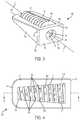
- FIG. 3is an isometric view of a wedge according to an embodiment of the invention.
- FIG. 4is a top view of the wedge of FIG. 3 .
- FIG. 5is a cross-sectional view of the wedge of FIG. 4 taken along line 5 - 5 .
- FIG. 6is an isometric view of a wedge according to an embodiment of the invention.
- FIG. 7Ais a rear view of a wedge according to an embodiment of the invention in an unlocked position.
- FIG. 7Bis a side view of the wedge of FIG. 7A in the unlocked position.
- FIG. 7Cis a rear view of the wedge of FIG. 7A in the locked position.
- FIG. 7Dis a side view of the wedge of FIG. 7A in locked position.
- FIG. 8is a side view of the wedge according to FIG. 3 during an initial step of implanting the wedge into the distal radius fracture.
- FIG. 9is a side view of the wedge according to FIG. 3 intermediate the implantation of the wedge into the distal radius fracture.
- FIG. 10is a side view of the wedge according to FIG. 3 after implantation of the wedge into the distal radius fracture has been completed.
- axialmeans along or parallel to the longitudinal axis of the implant device and “radial” means in the perpendicular direction thereto.
- “Rotation”refers to rotation about the longitudinal axis unless otherwise described.
- “Interior”means radially inward, either toward or facing the longitudinal axis, and “exterior” means radially outward or away from the longitudinal axis.
- proximal and distalrespectively, mean the end of the device nearest the surgeon during a surgical implantation procedure and the opposite end of the device furthest from the surgeon during the surgical implantation procedure.
- a reduced fracturerefers to a reduced distal radius fracture
- the devices and methods described hereinaftercan be used to fixate any fracture, naturally occurring or surgeon-induced, such as would be the case in performing a high tibial osteotomy as disclosed in U.S. Pat. Nos. 8,241,292; 8,926,618; 8,192,441; and U.S. Patent Publication No. 2009/0157190, the methods of which are each incorporated by reference in their entirety herein as if set forth fully herein.
- FIG. 1is a schematic anteroposterior view of a wrist, illustrating a distal radius fracture 15 in the radius 10 . Also shown is an ulna 12 .
- the distal radial bone fracture 15is situated on the radial side 14 of the radius 10 opposite the ulnar side 16 and is located in the metaphysis 18 of the radius 10 , between the diaphysis 20 and the epiphysis 22 .
- a metaphyseal void(shaded) is present on the radial side 14 of the radius 10 . Metaphyseal voids may be surgeon-induced in connection with a surgical procedure or occur as a result of trauma.
- FIG. 2illustrates a schematic side view of the distal radial bone fracture 15 , viewed from the radial side of the wrist.
- FIG. 2illustrates only the radius 10 , as the ulna 12 is substantially hidden behind the radius 10 .
- the radial viewdepicts that the bone fracture 15 is located predominantly on the dorsal aspect 24 of the radius 10 , opposite the volar side 26 , and has created a metaphyseal void (shaded) on the dorsal aspect 24 of the radius 10 .
- the distal radius fracture 15 illustrated in FIGS. 1 and 2is an exemplary illustration of an unstable, extra-articular fracture, i.e., the fracture is located outside of a joint.
- This type of fracture 15can lead to many long-term complications including dorsal comminution (i.e., pulverization of the bone on the dorsal side 24 of the radius 10 ), which may also result in loss of radial height (i.e., loss of height of the bone on the radial side 14 of the radius 10 ).
- the fracture 15may result in loss of volar tilt (i.e., loss of tilt of the bone towards the volar side 26 of the radius 10 ).
- the fracture 15may result in a radial shift (i.e., shift of the bone towards the radial side 14 of the radius 10 ) or a shortening of the radial column.
- a wedge 100is shown for maintaining reduction in a reduced distal radius fracture 15 or otherwise fixating adjacent bone.
- the wedge 100has a longitudinal axis L and includes a body 110 and an anchorage reinforcement member 140 , as described hereinafter, for maintaining reduction of a reduced fracture.
- the wedge 100is manufactured from a hard, non-compliant material such as stainless steel, titanium, other metal, non-metallic, or specialized medical grade polymer configured to conform to a fractured site of interest.
- the wedge 100is preferably fabricated by additive manufacturing techniques, e.g., by any one or any combination of fused deposition modeling (FDM), selective laser sintering (SLS), selective laser melting (SLM), electron beam melting (EBM), and other appropriate 3D printing technologies known to those of skill in the art, including fabrication processes disclosed in U.S. Pat. Nos. 7,537,664; 8,728,387; 9,180,010; and 9,456,901, the disclosures of which are hereby incorporated by reference in their entireties herein as if fully set forth herein.
- FDMfused deposition modeling
- SLSselective laser sintering
- SLMselective laser melting
- EBMelectron beam melting
- the body 110is generally wedge-shaped and extends along the longitudinal axis L from a proximal end wall 112 to a distal end wall 114 .
- the body 110may be any suitable shape, in addition to a wedge, such as conical, a rectangular prism, or U-shaped, to the extent that the body 110 provides support to bone, alone or in combination with the anchorage reinforcement member 140 as described hereinafter.
- the body 110may include a tapered first, or top, surface 116 and a tapered second, or bottom, surface 118 .
- the top surface 116extends from an upper end 120 of the proximal end wall 112 to the distal end wall 114 and tapers toward the longitudinal axis L in the proximal to distal direction while the tapered bottom surface 118 extends from a lower end 122 of the proximal end wall 112 to the distal end wall 114 and tapers toward the longitudinal axis L in the proximal to distal direction.
- the proximal end wall 112has a greater height than the distal end wall 114 such that as the wedge 100 is implanted into the metaphyseal void (shaded area of FIGS.
- the tapered top and bottom surfaces 116 , 118force apart and stabilize the diaphysis 20 and the epiphysis 22 portions of the radius 10 . More particularly, the tapered top and bottom surfaces 116 , 118 prevent the diaphysis 20 from collapsing toward the epiphysis 22 and also provide lateral support to prevent lateral shifting and/or pivoting of the diaphysis 20 and the epiphysis 22 relative to one another.
- the top surface 116 and the bottom surface 118have mirrored inclinations such that an angle A 1 , formed between the proximal end wall 112 and the top surface 116 , is equal in degree and mirrored with respect to the longitudinal axis L, relative to an angle A 2 , formed between the proximal end wall 112 and the bottom surface 118 .
- the tapered top surface 116 and the tapered bottom surface 118could have dual (or different) inclinations.
- the size of the wedge 100 and the inclinations of the top and bottom surfaces 116 , 118could be modified based upon the size and shape of particular fractures or metaphyseal voids.
- an exterior portion of the top surface 116 and an exterior portion of the bottom surface 118are flat and preferably smooth in order to facilitate insertion of the wedge 100 into the distal radius fracture 15 .
- the top and bottom surfaces 116 , 118 of the body 110slide against a surface of the diaphysis 20 adjacent the metaphyseal void and a surface of the epiphysis 22 adjacent the metaphyseal void while the anchorage reinforcement member 140 secures the wedge 100 in a desired position.
- the exterior portions of the top surface 116 and the bottom surface 118may be roughened or include roughed areas to ensure immobilization and bone-ingrowth after implantation. Any bone growth-inducing surfaces as are known are contemplated.
- the body 110also includes lateral walls 124 extending from the proximal end wall 112 to the distal end wall 114 .
- the proximal end wall 112 , the distal end wall 114 , and the lateral walls 124are perpendicularly positioned to the longitudinal axis L, however, in embodiments not shown, the proximal end wall 112 , the distal end wall 114 , and/or the lateral end walls 124 may be offset therefrom to accommodate different angles of implantation.
- an aperture 126is defined through the top surface 116 and the bottom surface 118 , forming a cavity C within the body 110 for receiving the anchorage reinforcement member 140 .
- a bore 128may be defined through the proximal end wall 112 to provide a surgeon with access to the anchorage reinforcement member 140 , as is described in more detail hereinafter.
- the anchorage reinforcement member 140is a screw and is rotatably secured within the cavity C of the body 110 and adapted to engage with the diaphysis 20 and the epiphysis 22 portions of the radius 10 to maintain reduction of the reduced bone fracture 15 .
- the screw 140includes a screw body 142 and a self-tapping helical thread 144 extending radially outward therefrom.
- the screw body 142is generally frustoconical in shape and rotatably received within the cavity C of the body 110 such that the screw body 142 extends along the longitudinal axis L.
- the screw body 142includes a head 146 provided at a proximal end 148 thereof.
- the head 146may define a recess 150 for receiving an implantation device 180 (shown in FIGS. 8 and 9 ), for example, a hex key having a tip corresponding in shape to the recess 150 .
- the head 146is aligned with the bore 128 defined in the proximal end wall 112 such that a surgeon can access the recess 150 via the bore 128 .
- the recess 150is hexagonal in shape, however, it is understood that the recess can be any suitable shape, such as squared, crossed, triangular, octagonal, etc. corresponding to the tip of the implantation device 180 .
- the screw body 142may include a tapered sidewall 152 defining a hollow reservoir R therein configured to hold bone graft material such as autograft or allograft for facilitating osteogenesis after implantation.
- the sidewall 152may extend from a circumferential edge 156 of the proximal end 148 to a distal end 154 and taper toward the longitudinal axis L in the proximal to distal direction.
- the taper of the sidewall 152may correspond to the inclination of the top and bottom surfaces 116 , 118 of the body 110 .
- a plurality of openings 158may be formed between adjacent crests 160 of the helical self-tapping thread 144 for permitting bone growth from the bone graft material within the reservoir R. Bone growth is typically desired from within the reservoir R to areas outside the implant including the metaphyseal void. The bone growth material may be inserted into the reservoir R before the screw 140 is rotated into place and/or after it is fully or partially inserted.
- the devicemay be structured such that the bone graft material can dispel from the openings 158 during implantation, it is not necessary. Bone growth will ensue in any event. However, it may be desirable to fill the reservoir R with bone cement and ensure that the bone cement flows from the openings 158 either upon insertion or after implantation in which case the bone cement can be inserted and pressured into the reservoir R such that the bone cement is extruded out of the openings 158 for fixation.
- polymerscan be built into the reservoir R, and upon implantation a sonic melting technique is employed to melt the polymer and have it flow out of the openings 158 for fixation. Of course, the polymer can be inserted post-implantation either in a flowable, solid or other form after implantation.
- U.S. Pat. Nos. 7,335,205; 9,226,784; and 9,724,206each of which is incorporated herein by reference as if fully set forth herein, discloses ultrasonic welding technologies applicable herein.
- the self-tapping helical thread 144extends through the aperture 126 defined in the top surface 116 and the bottom surface 118 of the body 110 such that the thread 144 contacts and taps into the radius 10 during implantation of the wedge 100 . Accordingly, the self-tapping helical thread 144 secures the wedge 100 in the metaphyseal void preventing the wedge 100 from backing out (being proximally displaced from the metaphyseal void).
- the self-tapping helical thread 144may be continuous or non-continuous and may be of uniform or varying pitch.
- the wedge 100may further include an attachment plate 162 provided at the proximal end wall 112 of the body 110 as an additional feature for preventing the wedge 100 from backing out of the metaphyseal void after implantation.
- the attachment plate 162may be monolithically formed with the body 110 or manufactured as a separate and removable piece, attachable to the proximal end wall 112 of the wedge 100 before or after implantation of the wedge 100 .
- the attachment plate 162defines a pair of screw holes 164 through which screws (not shown) can be inserted to secure the attachment plate 162 to the radius 10 in order to further secure the wedge 100 and to prevent the same from backing out of the metaphyseal void.
- the wedge body 110is substantially the same as previously described, however, the wedge body 110 may be pushed or slide into the metaphyseal void simultaneously with, or separate from, the anchorage reinforcement member 140 .
- the anchorage reinforcement member 140may additionally or alternatively include a securement member such as teeth, barbs, protrusions, or similar securement member, as is known in that art, to anchor the anchorage reinforcement member 140 , along with the attached body 110 , to the radius 10 upon a translational and/or rotational movement.
- the securement membersmay be provided on a single side, or opposing sides, of the sidewall 152 ′ of the anchorage reinforcement member 140 ′ such that the wedge 100 is transitionable between an unlocked position ( FIGS. 7A and 7B ), in which the securement members do not extend from the cavity of the wedge 100 ′ and a locked position ( FIGS. 7C and 7D ), in which the securement members extend through the cavity of the wedge. While in the unlocked position ( FIGS.
- a surgeonmay simultaneously, or separately slide the wedge body 110 ′ and the anchorage reinforcement member 140 ′, into a desired position within the metaphyseal void and then rotate the anchorage reinforcement member 140 ′ to a locked position, via a rotation of the anchorage reinforcement member, which may be any rotation including, for example, a 90° rotation, such that the securement member extends from the cavity and engages with the radius 10 to secure the wedge device 100 ′ to the bone.
- FIGS. 8-10illustrate a method of using the wedge 100 during osteotomy or to otherwise to maintain a reduced fracture.
- a distal end wall 114is position within the metaphyseal void.
- the epiphysis 22has tilted downward toward the diaphysis 20 .
- a tip of the implantation device 180is then inserted through the bore 128 defined in the proximal end wall 112 of the body 110 and into the correspondingly shaped recess 150 defined in the head 146 of the screw.
- the surgeonrotates the screw 140 clockwise relative to the body 110 which causes the self-tapping helical thread 144 to tap, or cut into, a surface of the diaphysis 20 adjacent the metaphyseal void and a surface of the epiphysis 22 adjacent the metaphyseal void.
- the smooth exterior surface of the tapered top and bottom surface 116 , 118slides against a surface of the diaphysis 20 adjacent the metaphyseal void and a surface of the epiphysis 22 adjacent the metaphyseal void to facilitate wedging of the body 110 into the metaphyseal void, in the distal direction, as shown in FIGS. 9 and 10 .
- the tapered top and bottom surfaces 116 , 118spread apart and sustain a separating force between the diaphysis 20 and epiphysis 22 portions of the radius 10 .
- the wedge 100has been fully inserted into the metaphyseal void ( FIG. 10 ), such that the proximal end wall 112 sits within the radius 10 , the diaphysis 20 and epiphysis 22 portions of the radius 10 are returned to and secured in their proper alignment.
- the surgeonwhile in the unlocked position, the surgeon pushes or wedges the body 100 in the distal direction such that the body 100 slides against a surface of the diaphysis 20 adjacent the metaphyseal void and a surface of the epiphysis 22 adjacent the metaphyseal void until the body 110 has been positioned at a desired location.
- the surgeonthen rotates the anchorage reinforcement member 140 from the unlocked position ( FIGS. 7A and 7 B) to the locked position ( FIGS.
- a rotation of the anchorage reinforcement member 140which may be any rotation including a 90° rotation, such that the securement members extend from the apertures 126 and engage with and secure the anchorage reinforcement member 140 , along with the wedge body 110 , to the radius or other bone.
- the self-tapping screw 144 of one embodimentsecures the wedge 100 in place within the metaphyseal void thereby providing long-term stability to the wedge 100 until osteogenesis has occurred.
- the wedge 100may optionally be further fastened to the radius 10 by securing screws (not shown) thorough screw holes 164 defined in the attachment plate 162 and into the radius 10 .
Landscapes
- Health & Medical Sciences (AREA)
- Orthopedic Medicine & Surgery (AREA)
- Life Sciences & Earth Sciences (AREA)
- Surgery (AREA)
- Animal Behavior & Ethology (AREA)
- Veterinary Medicine (AREA)
- Public Health (AREA)
- Engineering & Computer Science (AREA)
- Biomedical Technology (AREA)
- Heart & Thoracic Surgery (AREA)
- General Health & Medical Sciences (AREA)
- Molecular Biology (AREA)
- Medical Informatics (AREA)
- Nuclear Medicine, Radiotherapy & Molecular Imaging (AREA)
- Neurology (AREA)
- Transplantation (AREA)
- Cardiology (AREA)
- Oral & Maxillofacial Surgery (AREA)
- Vascular Medicine (AREA)
- Prostheses (AREA)
- Surgical Instruments (AREA)
Abstract
Description
Claims (13)
Priority Applications (1)
| Application Number | Priority Date | Filing Date | Title |
|---|---|---|---|
| US16/137,903US10828077B2 (en) | 2017-09-22 | 2018-09-21 | Distal radius wedge screw |
Applications Claiming Priority (2)
| Application Number | Priority Date | Filing Date | Title |
|---|---|---|---|
| US201762562042P | 2017-09-22 | 2017-09-22 | |
| US16/137,903US10828077B2 (en) | 2017-09-22 | 2018-09-21 | Distal radius wedge screw |
Publications (2)
| Publication Number | Publication Date |
|---|---|
| US20190090922A1 US20190090922A1 (en) | 2019-03-28 |
| US10828077B2true US10828077B2 (en) | 2020-11-10 |
Family
ID=65808641
Family Applications (1)
| Application Number | Title | Priority Date | Filing Date |
|---|---|---|---|
| US16/137,903Active2038-10-11US10828077B2 (en) | 2017-09-22 | 2018-09-21 | Distal radius wedge screw |
Country Status (1)
| Country | Link |
|---|---|
| US (1) | US10828077B2 (en) |
Families Citing this family (5)
| Publication number | Priority date | Publication date | Assignee | Title |
|---|---|---|---|---|
| CN110680585B (en)* | 2019-09-30 | 2023-06-20 | 四川大学华西医院 | A reverse skin traction frame for children with bone fractures and its application method |
| CN111265342A (en)* | 2020-03-20 | 2020-06-12 | 宁波市第六医院 | A hemiradial head prosthesis structure |
| AU2021204642B2 (en)* | 2020-07-08 | 2023-08-31 | Nextremity Solutions, Inc. | Bone wedge device and method |
| WO2023064785A1 (en)* | 2021-10-12 | 2023-04-20 | Lee Randall F | System and method for a medical implant with integrated propulsors |
| CN117860325B (en)* | 2024-03-11 | 2024-10-15 | 北京大学第三医院(北京大学第三临床医学院) | Ankle lateral collateral ligament repair and reconstruction surgery fixation system |
Citations (47)
| Publication number | Priority date | Publication date | Assignee | Title |
|---|---|---|---|---|
| US2677369A (en) | 1952-03-26 | 1954-05-04 | Fred L Knowles | Apparatus for treatment of the spinal column |
| US4834757A (en) | 1987-01-22 | 1989-05-30 | Brantigan John W | Prosthetic implant |
| WO1990011740A1 (en) | 1989-04-08 | 1990-10-18 | Robert Bosch Gmbh | Artificial spinal disc |
| FR2703580A1 (en) | 1993-03-03 | 1994-10-14 | Robert Gilles | Intersomatic cervical cage |
| EP0664994A1 (en) | 1994-01-26 | 1995-08-02 | BIOMAT(S.a.r.l.) | Interbody vertebral cage |
| DE4409392A1 (en) | 1994-03-18 | 1995-09-21 | Biedermann Motech Gmbh | Adjustable vertebral body |
| US5458638A (en) | 1989-07-06 | 1995-10-17 | Spine-Tech, Inc. | Non-threaded spinal implant |
| FR2710519B1 (en) | 1993-09-29 | 1996-01-05 | Dominique Robine | Lumbar interbody fusion cage (CH). |
| FR2724312A1 (en) | 1995-04-21 | 1996-03-15 | Alby Albert | Inter-somatic dorsal-lumber spacer |
| WO1996014809A1 (en) | 1994-11-16 | 1996-05-23 | Atlas Implants | Implant for the fusion of two adjacent bony bodies, particularly two consecutive vertebrae |
| DE29519418U1 (en) | 1995-12-07 | 1996-05-23 | Diehl, Klaus, Prof. Dr., 66123 Saarbrücken | Self-tapping banjo bolt |
| FR2727004A1 (en) | 1994-11-18 | 1996-05-24 | Euros Sa | Lumbar and lumbar-sacral posterior stabiliser |
| EP0716840A2 (en) | 1994-12-12 | 1996-06-19 | Surgical Dynamics, Inc. | Conically-shaped fusion cage and method of implantation |
| WO1996027339A1 (en) | 1995-03-08 | 1996-09-12 | Advanced Microbotics Corporation | Spinal disc implant |
| DE29612269U1 (en) | 1996-07-15 | 1996-09-12 | Aesculap Ag, 78532 Tuttlingen | Vertebral fusion implant |
| EP0732093A2 (en) | 1995-02-17 | 1996-09-18 | Sofamor Danek Group, Inc. | Interbody spinal fusion implants |
| WO1996040016A2 (en) | 1994-03-18 | 1996-12-19 | Madhavan Pisharodi | Intervertebral disk stabilizer and instrument for reduction of spondylolisthesis |
| US5609635A (en) | 1988-06-28 | 1997-03-11 | Michelson; Gary K. | Lordotic interbody spinal fusion implants |
| FR2727003B1 (en) | 1994-11-18 | 1997-04-18 | Euros Sa | ANTERIOR STABILIZATION DEVICE OF THE LOMBO-SACRE SPINE |
| WO1997015246A1 (en) | 1995-10-20 | 1997-05-01 | Synthes Ag Chur | Intervertebral implant with cage and rotating element |
| US5776199A (en) | 1988-06-28 | 1998-07-07 | Sofamor Danek Properties | Artificial spinal fusion implants |
| US5800550A (en) | 1996-03-13 | 1998-09-01 | Sertich; Mario M. | Interbody fusion cage |
| US5860973A (en) | 1995-02-27 | 1999-01-19 | Michelson; Gary Karlin | Translateral spinal implant |
| US5865845A (en) | 1996-03-05 | 1999-02-02 | Thalgott; John S. | Prosthetic intervertebral disc |
| US6008433A (en)* | 1998-04-23 | 1999-12-28 | Stone; Kevin R. | Osteotomy wedge device, kit and methods for realignment of a varus angulated knee |
| US6129763A (en) | 1996-09-13 | 2000-10-10 | Chauvin; Jean-Luc | Expandable osteosynthesis cage |
| US20020038123A1 (en)* | 2000-09-20 | 2002-03-28 | Visotsky Jeffrey L. | Osteotomy implant |
| US6824564B2 (en)* | 1997-04-25 | 2004-11-30 | Stryker France, Sas | Two-part intersomatic implant |
| US7335205B2 (en) | 2001-03-02 | 2008-02-26 | Woodwelding Ag | Implants, device and method for joining tissue parts |
| US7537664B2 (en) | 2002-11-08 | 2009-05-26 | Howmedica Osteonics Corp. | Laser-produced porous surface |
| US20090157190A1 (en) | 2007-12-13 | 2009-06-18 | Howmedica Inc. | Osteotomy spacer |
| US7594932B2 (en)* | 2005-12-29 | 2009-09-29 | International Spinal Innovations, Llc | Apparatus for anterior intervertebral spinal fixation and fusion |
| US8182489B2 (en) | 2007-08-07 | 2012-05-22 | Arthrex, Inc. | Method and apparatus for performing an open wedge osteotomy |
| US8192441B2 (en) | 2008-10-03 | 2012-06-05 | Howmedica Osteonics Corp. | High tibial osteotomy instrumentation |
| US8241292B2 (en) | 2006-06-30 | 2012-08-14 | Howmedica Osteonics Corp. | High tibial osteotomy system |
| US20130150969A1 (en)* | 2005-06-03 | 2013-06-13 | Arthrodisc, L.L.C. | Spinner body |
| US20130211522A1 (en) | 2011-08-16 | 2013-08-15 | Arnold-Peter C. Weiss | Wedge shaped fracture fixation devices and methods for using the same |
| US20140135927A1 (en)* | 2012-11-12 | 2014-05-15 | Paul Pavlov | Interbody interference implant and instrumentation |
| US8728387B2 (en) | 2005-12-06 | 2014-05-20 | Howmedica Osteonics Corp. | Laser-produced porous surface |
| US8900310B2 (en)* | 2012-04-05 | 2014-12-02 | Zimmer Spine, Inc. | Interbody spacer |
| US8926618B2 (en) | 2007-04-19 | 2015-01-06 | Howmedica Osteonics Corp. | Cutting guide with internal distraction |
| US9180010B2 (en) | 2012-04-06 | 2015-11-10 | Howmedica Osteonics Corp. | Surface modified unit cell lattice structures for optimized secure freeform fabrication |
| US9226784B2 (en) | 2008-05-01 | 2016-01-05 | Woodwelding Ag | Device and method for establishing an anchorage in tissue |
| US9456904B2 (en)* | 2012-10-23 | 2016-10-04 | Spinesmith Partners, L.P. | Facet fixation device |
| US9456901B2 (en) | 2004-12-30 | 2016-10-04 | Howmedica Osteonics Corp. | Laser-produced porous structure |
| US20170189188A1 (en)* | 2014-12-29 | 2017-07-06 | Yechiel Gotfried | Orthopedic implants |
| US9724206B2 (en) | 2006-09-20 | 2017-08-08 | Woodwelding Ag | Device to be implanted in human or animal tissue and method for implanting and assembling the device |
- 2018
- 2018-09-21USUS16/137,903patent/US10828077B2/enactiveActive
Patent Citations (52)
| Publication number | Priority date | Publication date | Assignee | Title |
|---|---|---|---|---|
| US2677369A (en) | 1952-03-26 | 1954-05-04 | Fred L Knowles | Apparatus for treatment of the spinal column |
| US4834757A (en) | 1987-01-22 | 1989-05-30 | Brantigan John W | Prosthetic implant |
| US5776199A (en) | 1988-06-28 | 1998-07-07 | Sofamor Danek Properties | Artificial spinal fusion implants |
| US5609635A (en) | 1988-06-28 | 1997-03-11 | Michelson; Gary K. | Lordotic interbody spinal fusion implants |
| WO1990011740A1 (en) | 1989-04-08 | 1990-10-18 | Robert Bosch Gmbh | Artificial spinal disc |
| US5458638A (en) | 1989-07-06 | 1995-10-17 | Spine-Tech, Inc. | Non-threaded spinal implant |
| FR2703580A1 (en) | 1993-03-03 | 1994-10-14 | Robert Gilles | Intersomatic cervical cage |
| FR2710519B1 (en) | 1993-09-29 | 1996-01-05 | Dominique Robine | Lumbar interbody fusion cage (CH). |
| EP0664994A1 (en) | 1994-01-26 | 1995-08-02 | BIOMAT(S.a.r.l.) | Interbody vertebral cage |
| WO1996040016A2 (en) | 1994-03-18 | 1996-12-19 | Madhavan Pisharodi | Intervertebral disk stabilizer and instrument for reduction of spondylolisthesis |
| DE4409392A1 (en) | 1994-03-18 | 1995-09-21 | Biedermann Motech Gmbh | Adjustable vertebral body |
| WO1996014809A1 (en) | 1994-11-16 | 1996-05-23 | Atlas Implants | Implant for the fusion of two adjacent bony bodies, particularly two consecutive vertebrae |
| FR2727003B1 (en) | 1994-11-18 | 1997-04-18 | Euros Sa | ANTERIOR STABILIZATION DEVICE OF THE LOMBO-SACRE SPINE |
| FR2727004A1 (en) | 1994-11-18 | 1996-05-24 | Euros Sa | Lumbar and lumbar-sacral posterior stabiliser |
| EP0716840A2 (en) | 1994-12-12 | 1996-06-19 | Surgical Dynamics, Inc. | Conically-shaped fusion cage and method of implantation |
| EP0732093A2 (en) | 1995-02-17 | 1996-09-18 | Sofamor Danek Group, Inc. | Interbody spinal fusion implants |
| US5860973A (en) | 1995-02-27 | 1999-01-19 | Michelson; Gary Karlin | Translateral spinal implant |
| WO1996027339A1 (en) | 1995-03-08 | 1996-09-12 | Advanced Microbotics Corporation | Spinal disc implant |
| FR2724312A1 (en) | 1995-04-21 | 1996-03-15 | Alby Albert | Inter-somatic dorsal-lumber spacer |
| WO1997015246A1 (en) | 1995-10-20 | 1997-05-01 | Synthes Ag Chur | Intervertebral implant with cage and rotating element |
| DE29519418U1 (en) | 1995-12-07 | 1996-05-23 | Diehl, Klaus, Prof. Dr., 66123 Saarbrücken | Self-tapping banjo bolt |
| US5865845A (en) | 1996-03-05 | 1999-02-02 | Thalgott; John S. | Prosthetic intervertebral disc |
| US5800550A (en) | 1996-03-13 | 1998-09-01 | Sertich; Mario M. | Interbody fusion cage |
| DE29612269U1 (en) | 1996-07-15 | 1996-09-12 | Aesculap Ag, 78532 Tuttlingen | Vertebral fusion implant |
| US6129763A (en) | 1996-09-13 | 2000-10-10 | Chauvin; Jean-Luc | Expandable osteosynthesis cage |
| US6824564B2 (en)* | 1997-04-25 | 2004-11-30 | Stryker France, Sas | Two-part intersomatic implant |
| US8840666B2 (en)* | 1997-04-25 | 2014-09-23 | Stryker France | Two part intersomatic implant |
| US8449613B2 (en)* | 1997-04-25 | 2013-05-28 | Stryker France | Two part intersomatic implant |
| US6855168B2 (en)* | 1997-04-25 | 2005-02-15 | Stryker France | Intersomatic implants in two parts |
| US6008433A (en)* | 1998-04-23 | 1999-12-28 | Stone; Kevin R. | Osteotomy wedge device, kit and methods for realignment of a varus angulated knee |
| US20020038123A1 (en)* | 2000-09-20 | 2002-03-28 | Visotsky Jeffrey L. | Osteotomy implant |
| US7335205B2 (en) | 2001-03-02 | 2008-02-26 | Woodwelding Ag | Implants, device and method for joining tissue parts |
| US7537664B2 (en) | 2002-11-08 | 2009-05-26 | Howmedica Osteonics Corp. | Laser-produced porous surface |
| US9456901B2 (en) | 2004-12-30 | 2016-10-04 | Howmedica Osteonics Corp. | Laser-produced porous structure |
| US20130150969A1 (en)* | 2005-06-03 | 2013-06-13 | Arthrodisc, L.L.C. | Spinner body |
| US10265187B2 (en)* | 2005-06-03 | 2019-04-23 | Arthrodisc, L.L.C. | Spinner body |
| US8728387B2 (en) | 2005-12-06 | 2014-05-20 | Howmedica Osteonics Corp. | Laser-produced porous surface |
| US7594932B2 (en)* | 2005-12-29 | 2009-09-29 | International Spinal Innovations, Llc | Apparatus for anterior intervertebral spinal fixation and fusion |
| US9463096B2 (en)* | 2005-12-29 | 2016-10-11 | International Spinal Innovations LLC | Apparatus for anterior intervertebral spinal fixation and fusion |
| US8241292B2 (en) | 2006-06-30 | 2012-08-14 | Howmedica Osteonics Corp. | High tibial osteotomy system |
| US9724206B2 (en) | 2006-09-20 | 2017-08-08 | Woodwelding Ag | Device to be implanted in human or animal tissue and method for implanting and assembling the device |
| US8926618B2 (en) | 2007-04-19 | 2015-01-06 | Howmedica Osteonics Corp. | Cutting guide with internal distraction |
| US8182489B2 (en) | 2007-08-07 | 2012-05-22 | Arthrex, Inc. | Method and apparatus for performing an open wedge osteotomy |
| US20090157190A1 (en) | 2007-12-13 | 2009-06-18 | Howmedica Inc. | Osteotomy spacer |
| US9226784B2 (en) | 2008-05-01 | 2016-01-05 | Woodwelding Ag | Device and method for establishing an anchorage in tissue |
| US8192441B2 (en) | 2008-10-03 | 2012-06-05 | Howmedica Osteonics Corp. | High tibial osteotomy instrumentation |
| US20130211522A1 (en) | 2011-08-16 | 2013-08-15 | Arnold-Peter C. Weiss | Wedge shaped fracture fixation devices and methods for using the same |
| US8900310B2 (en)* | 2012-04-05 | 2014-12-02 | Zimmer Spine, Inc. | Interbody spacer |
| US9180010B2 (en) | 2012-04-06 | 2015-11-10 | Howmedica Osteonics Corp. | Surface modified unit cell lattice structures for optimized secure freeform fabrication |
| US9456904B2 (en)* | 2012-10-23 | 2016-10-04 | Spinesmith Partners, L.P. | Facet fixation device |
| US20140135927A1 (en)* | 2012-11-12 | 2014-05-15 | Paul Pavlov | Interbody interference implant and instrumentation |
| US20170189188A1 (en)* | 2014-12-29 | 2017-07-06 | Yechiel Gotfried | Orthopedic implants |
Also Published As
| Publication number | Publication date |
|---|---|
| US20190090922A1 (en) | 2019-03-28 |
Similar Documents
| Publication | Publication Date | Title |
|---|---|---|
| US10828077B2 (en) | Distal radius wedge screw | |
| US11617606B2 (en) | Proximal humeral stabilization system | |
| US20240130866A1 (en) | Compound-arc, splined anchor | |
| US12419672B2 (en) | Implant with intramedullary portion and offset extramedullary portion | |
| EP3593745B1 (en) | Orthopedic screw and porous structures thereof | |
| US10357368B2 (en) | Sacroiliac joint implants and implantation methods | |
| US9486264B2 (en) | Systems and methods for the fixation or fusion of bone using compressive implants | |
| US20200078058A1 (en) | Flexible bone implant | |
| US20190262048A1 (en) | Apparatus, system and method for fusion of bone | |
| US8808336B2 (en) | Joint arthrodesis and arthroplasty | |
| KR101709357B1 (en) | Anchor-in-anchor system for use in bone fixation | |
| US8343200B2 (en) | Orthopedic screw system | |
| AU2005202820B2 (en) | Self-guiding threaded fastener | |
| US20150297276A1 (en) | Placement Tool For Bone Screw Assembly, And Systems and Methods Of Using Same | |
| US20250099140A1 (en) | Medical implants for generating fusion between two bones | |
| US20100036498A1 (en) | Fusion cage with reverse thread profile (rtp) | |
| JP2024530511A (en) | Bone fixation devices, systems, methods, and instruments | |
| US11918263B2 (en) | Mixed materials bone screw | |
| EP2363087B1 (en) | Fastening system for prostheses |
Legal Events
| Date | Code | Title | Description |
|---|---|---|---|
| FEPP | Fee payment procedure | Free format text:ENTITY STATUS SET TO UNDISCOUNTED (ORIGINAL EVENT CODE: BIG.); ENTITY STATUS OF PATENT OWNER: LARGE ENTITY | |
| STPP | Information on status: patent application and granting procedure in general | Free format text:DOCKETED NEW CASE - READY FOR EXAMINATION | |
| AS | Assignment | Owner name:HOWMEDICA OSTEONICS CORP., NEW JERSEY Free format text:ASSIGNMENT OF ASSIGNORS INTEREST;ASSIGNOR:BLUECHEL, TOBIAS;REEL/FRAME:048247/0051 Effective date:20190206 | |
| STPP | Information on status: patent application and granting procedure in general | Free format text:NON FINAL ACTION MAILED | |
| STPP | Information on status: patent application and granting procedure in general | Free format text:RESPONSE TO NON-FINAL OFFICE ACTION ENTERED AND FORWARDED TO EXAMINER | |
| STPP | Information on status: patent application and granting procedure in general | Free format text:NOTICE OF ALLOWANCE MAILED -- APPLICATION RECEIVED IN OFFICE OF PUBLICATIONS | |
| STPP | Information on status: patent application and granting procedure in general | Free format text:PUBLICATIONS -- ISSUE FEE PAYMENT VERIFIED | |
| STCF | Information on status: patent grant | Free format text:PATENTED CASE | |
| MAFP | Maintenance fee payment | Free format text:PAYMENT OF MAINTENANCE FEE, 4TH YEAR, LARGE ENTITY (ORIGINAL EVENT CODE: M1551); ENTITY STATUS OF PATENT OWNER: LARGE ENTITY Year of fee payment:4 |