US10827979B2 - Wearable monitoring device - Google Patents
Wearable monitoring deviceDownload PDFInfo
- Publication number
- US10827979B2 US10827979B2US15/262,528US201615262528AUS10827979B2US 10827979 B2US10827979 B2US 10827979B2US 201615262528 AUS201615262528 AUS 201615262528AUS 10827979 B2US10827979 B2US 10827979B2
- Authority
- US
- United States
- Prior art keywords
- optical
- tip
- light
- housing
- emitter
- Prior art date
- Legal status (The legal status is an assumption and is not a legal conclusion. Google has not performed a legal analysis and makes no representation as to the accuracy of the status listed.)
- Active, expires
Links
- 238000012806monitoring deviceMethods0.000title1
- 230000003287optical effectEffects0.000claimsabstractdescription326
- 230000033001locomotionEffects0.000claimsabstractdescription69
- 239000000463materialSubstances0.000claimsdescription63
- 238000000034methodMethods0.000claimsdescription25
- 238000004891communicationMethods0.000claimsdescription19
- 230000004888barrier functionEffects0.000claimsdescription11
- 230000008569processEffects0.000claimsdescription7
- 230000004044responseEffects0.000description58
- 230000007613environmental effectEffects0.000description42
- 238000012544monitoring processMethods0.000description33
- 210000004369bloodAnatomy0.000description31
- 239000008280bloodSubstances0.000description31
- 230000008878couplingEffects0.000description28
- 238000010168coupling processMethods0.000description28
- 238000005859coupling reactionMethods0.000description28
- 210000004204blood vesselAnatomy0.000description20
- 230000004962physiological conditionEffects0.000description20
- 230000017531blood circulationEffects0.000description18
- 229920003023plasticPolymers0.000description18
- 238000012545processingMethods0.000description18
- 238000001914filtrationMethods0.000description17
- 239000004033plasticSubstances0.000description17
- 210000003491skinAnatomy0.000description17
- 238000013461designMethods0.000description15
- 230000003993interactionEffects0.000description11
- 230000003595spectral effectEffects0.000description11
- 230000036541healthEffects0.000description10
- 230000000694effectsEffects0.000description9
- 239000000758substrateSubstances0.000description9
- 230000008901benefitEffects0.000description8
- 239000002207metaboliteSubstances0.000description8
- 230000035485pulse pressureEffects0.000description8
- 230000029058respiratory gaseous exchangeEffects0.000description8
- 238000001228spectrumMethods0.000description8
- 210000000707wristAnatomy0.000description8
- 230000036772blood pressureEffects0.000description7
- 229920001971elastomerPolymers0.000description7
- 230000005284excitationEffects0.000description7
- 229920001296polysiloxanePolymers0.000description7
- 239000005060rubberSubstances0.000description7
- 238000005070samplingMethods0.000description7
- 238000013459approachMethods0.000description6
- 230000005670electromagnetic radiationEffects0.000description6
- 239000007789gasSubstances0.000description6
- 238000005259measurementMethods0.000description6
- QVGXLLKOCUKJST-UHFFFAOYSA-Natomic oxygenChemical compound[O]QVGXLLKOCUKJST-UHFFFAOYSA-N0.000description5
- 238000009792diffusion processMethods0.000description5
- 230000002452interceptive effectEffects0.000description5
- 230000014759maintenance of locationEffects0.000description5
- 229910052760oxygenInorganic materials0.000description5
- 239000001301oxygenSubstances0.000description5
- 239000003814drugSubstances0.000description4
- 229940079593drugDrugs0.000description4
- 238000000605extractionMethods0.000description4
- 238000002955isolationMethods0.000description4
- 238000002106pulse oximetryMethods0.000description4
- 239000007779soft materialSubstances0.000description4
- CURLTUGMZLYLDI-UHFFFAOYSA-NCarbon dioxideChemical compoundO=C=OCURLTUGMZLYLDI-UHFFFAOYSA-N0.000description3
- 241000282412HomoSpecies0.000description3
- 241001465754MetazoaSpecies0.000description3
- 238000010521absorption reactionMethods0.000description3
- 230000008859changeEffects0.000description3
- 238000001514detection methodMethods0.000description3
- 210000000624ear auricleAnatomy0.000description3
- 230000006870functionEffects0.000description3
- 239000011521glassSubstances0.000description3
- 230000001965increasing effectEffects0.000description3
- 230000004298light responseEffects0.000description3
- 230000004060metabolic processEffects0.000description3
- 239000002184metalSubstances0.000description3
- 229910052751metalInorganic materials0.000description3
- 210000000056organAnatomy0.000description3
- 230000035479physiological effects, processes and functionsEffects0.000description3
- 229920000642polymerPolymers0.000description3
- 230000008093supporting effectEffects0.000description3
- 210000001519tissueAnatomy0.000description3
- 238000012935AveragingMethods0.000description2
- BPYKTIZUTYGOLE-IFADSCNNSA-NBilirubinChemical compoundN1C(=O)C(C)=C(C=C)\C1=C\C1=C(C)C(CCC(O)=O)=C(CC2=C(C(C)=C(\C=C/3C(=C(C=C)C(=O)N\3)C)N2)CCC(O)=O)N1BPYKTIZUTYGOLE-IFADSCNNSA-N0.000description2
- WQZGKKKJIJFFOK-GASJEMHNSA-NGlucoseNatural productsOC[C@H]1OC(O)[C@H](O)[C@@H](O)[C@@H]1OWQZGKKKJIJFFOK-GASJEMHNSA-N0.000description2
- 230000002238attenuated effectEffects0.000description2
- 230000005540biological transmissionEffects0.000description2
- 230000007177brain activityEffects0.000description2
- 229910002092carbon dioxideInorganic materials0.000description2
- 230000002612cardiopulmonary effectEffects0.000description2
- 210000004027cellAnatomy0.000description2
- HVYWMOMLDIMFJA-DPAQBDIFSA-NcholesterolChemical compoundC1C=C2C[C@@H](O)CC[C@]2(C)[C@@H]2[C@@H]1[C@@H]1CC[C@H]([C@H](C)CCCC(C)C)[C@@]1(C)CC2HVYWMOMLDIMFJA-DPAQBDIFSA-N0.000description2
- 239000000470constituentSubstances0.000description2
- 230000036757core body temperatureEffects0.000description2
- 210000000613ear canalAnatomy0.000description2
- 210000005069earsAnatomy0.000description2
- 239000003792electrolyteSubstances0.000description2
- 238000005516engineering processMethods0.000description2
- 238000002474experimental methodMethods0.000description2
- 239000008103glucoseSubstances0.000description2
- 210000003128headAnatomy0.000description2
- 230000036571hydrationEffects0.000description2
- 238000006703hydration reactionMethods0.000description2
- 230000001976improved effectEffects0.000description2
- 230000001939inductive effectEffects0.000description2
- JVTAAEKCZFNVCJ-UHFFFAOYSA-Nlactic acidChemical compoundCC(O)C(O)=OJVTAAEKCZFNVCJ-UHFFFAOYSA-N0.000description2
- 206010025482malaiseDiseases0.000description2
- 230000013011matingEffects0.000description2
- 238000012986modificationMethods0.000description2
- 230000004048modificationEffects0.000description2
- 210000003205muscleAnatomy0.000description2
- 238000013186photoplethysmographyMethods0.000description2
- 230000001766physiological effectEffects0.000description2
- 108090000623proteins and genesProteins0.000description2
- 102000004169proteins and genesHuman genes0.000description2
- 230000008929regenerationEffects0.000description2
- 238000011069regeneration methodMethods0.000description2
- 239000000126substanceSubstances0.000description2
- 230000009747swallowingEffects0.000description2
- 239000004753textileSubstances0.000description2
- 239000012780transparent materialSubstances0.000description2
- 210000003454tympanic membraneAnatomy0.000description2
- XLYOFNOQVPJJNP-UHFFFAOYSA-NwaterSubstancesOXLYOFNOQVPJJNP-UHFFFAOYSA-N0.000description2
- 208000019901Anxiety diseaseDiseases0.000description1
- 241000894006BacteriaSpecies0.000description1
- 229920002799BoPETPolymers0.000description1
- 108020004414DNAProteins0.000description1
- 239000004593EpoxySubstances0.000description1
- 108010010803GelatinProteins0.000description1
- 102000001554HemoglobinsHuman genes0.000description1
- 108010054147HemoglobinsProteins0.000description1
- 206010020751HypersensitivityDiseases0.000description1
- 206010061218InflammationDiseases0.000description1
- 206010049816Muscle tightnessDiseases0.000description1
- 239000005041Mylar™Substances0.000description1
- 208000032140SleepinessDiseases0.000description1
- 206010041349SomnolenceDiseases0.000description1
- 241000700605VirusesSpecies0.000description1
- 238000005299abrasionMethods0.000description1
- 230000009471actionEffects0.000description1
- 230000003044adaptive effectEffects0.000description1
- 230000036626alertnessEffects0.000description1
- 210000003423ankleAnatomy0.000description1
- 230000036506anxietyEffects0.000description1
- 230000037007arousalEffects0.000description1
- 210000001367arteryAnatomy0.000description1
- 230000000386athletic effectEffects0.000description1
- 230000006472autoimmune responseEffects0.000description1
- 230000009286beneficial effectEffects0.000description1
- WQZGKKKJIJFFOK-VFUOTHLCSA-Nbeta-D-glucoseChemical compoundOC[C@H]1O[C@@H](O)[C@H](O)[C@@H](O)[C@@H]1OWQZGKKKJIJFFOK-VFUOTHLCSA-N0.000description1
- 230000000903blocking effectEffects0.000description1
- 230000037396body weightEffects0.000description1
- 230000037182bone densityEffects0.000description1
- 210000004556brainAnatomy0.000description1
- 235000019577caloric intakeNutrition0.000description1
- 239000001569carbon dioxideSubstances0.000description1
- 230000000747cardiac effectEffects0.000description1
- 210000001715carotid arteryAnatomy0.000description1
- 210000004004carotid artery internalAnatomy0.000description1
- 230000001413cellular effectEffects0.000description1
- 238000006243chemical reactionMethods0.000description1
- 235000012000cholesterolNutrition0.000description1
- 238000010954commercial manufacturing processMethods0.000description1
- 230000000052comparative effectEffects0.000description1
- 230000003750conditioning effectEffects0.000description1
- 238000010276constructionMethods0.000description1
- 230000001351cycling effectEffects0.000description1
- 230000002354daily effectEffects0.000description1
- 210000004207dermisAnatomy0.000description1
- 235000001916dietingNutrition0.000description1
- 230000037228dieting effectEffects0.000description1
- 230000004069differentiationEffects0.000description1
- 210000002249digestive systemAnatomy0.000description1
- 238000004980dosimetryMethods0.000description1
- 210000000883ear externalAnatomy0.000description1
- 210000003027ear innerAnatomy0.000description1
- 238000009429electrical wiringMethods0.000description1
- 210000002615epidermisAnatomy0.000description1
- 125000003700epoxy groupChemical group0.000description1
- 239000000284extractSubstances0.000description1
- 210000003414extremityAnatomy0.000description1
- 230000035558fertilityEffects0.000description1
- 239000000835fiberSubstances0.000description1
- 210000003811fingerAnatomy0.000description1
- 229920000159gelatinPolymers0.000description1
- 239000008273gelatinSubstances0.000description1
- 235000019322gelatineNutrition0.000description1
- 235000011852gelatine dessertsNutrition0.000description1
- 239000003292glueSubstances0.000description1
- 239000003163gonadal steroid hormoneSubstances0.000description1
- 230000035876healingEffects0.000description1
- 238000009532heart rate measurementMethods0.000description1
- 229910001385heavy metalInorganic materials0.000description1
- 239000005556hormoneSubstances0.000description1
- 229940088597hormoneDrugs0.000description1
- 235000003642hungerNutrition0.000description1
- 230000036039immunityEffects0.000description1
- 230000006872improvementEffects0.000description1
- 208000015181infectious diseaseDiseases0.000description1
- 230000004054inflammatory processEffects0.000description1
- 230000010354integrationEffects0.000description1
- 239000004310lactic acidSubstances0.000description1
- 235000014655lactic acidNutrition0.000description1
- 150000002632lipidsChemical class0.000description1
- 238000004020luminiscence typeMethods0.000description1
- 230000003340mental effectEffects0.000description1
- 229910001092metal group alloyInorganic materials0.000description1
- 239000010445micaSubstances0.000description1
- 229910052618mica groupInorganic materials0.000description1
- 239000000203mixtureSubstances0.000description1
- 230000036651moodEffects0.000description1
- 231100000219mutagenicToxicity0.000description1
- 230000003505mutagenic effectEffects0.000description1
- 230000000926neurological effectEffects0.000description1
- 230000007935neutral effectEffects0.000description1
- 230000016087ovulationEffects0.000description1
- 239000003973paintSubstances0.000description1
- 230000000737periodic effectEffects0.000description1
- 239000003016pheromoneSubstances0.000description1
- 230000037081physical activityEffects0.000description1
- 238000000554physical therapyMethods0.000description1
- 230000035790physiological processes and functionsEffects0.000description1
- 230000006461physiological responseEffects0.000description1
- 229920000647polyepoxidePolymers0.000description1
- 230000035935pregnancyEffects0.000description1
- 230000005855radiationEffects0.000description1
- 230000009467reductionEffects0.000description1
- 230000011514reflexEffects0.000description1
- 230000001568sexual effectEffects0.000description1
- 231100000430skin reactionToxicity0.000description1
- 230000037321sleepinessEffects0.000description1
- 238000004611spectroscopical analysisMethods0.000description1
- 210000000130stem cellAnatomy0.000description1
- 238000007920subcutaneous administrationMethods0.000description1
- 230000003319supportive effectEffects0.000description1
- 210000004243sweatAnatomy0.000description1
- 230000035922thirstEffects0.000description1
- 210000003371toeAnatomy0.000description1
- 231100000167toxic agentToxicity0.000description1
- 239000003440toxic substanceSubstances0.000description1
- 239000003053toxinSubstances0.000description1
- 231100000765toxinToxicity0.000description1
- 108700012359toxinsProteins0.000description1
- 238000012549trainingMethods0.000description1
- 239000012855volatile organic compoundSubstances0.000description1
- 230000002618waking effectEffects0.000description1
Images


Classifications
- A—HUMAN NECESSITIES
- A61—MEDICAL OR VETERINARY SCIENCE; HYGIENE
- A61B—DIAGNOSIS; SURGERY; IDENTIFICATION
- A61B5/00—Measuring for diagnostic purposes; Identification of persons
- A61B5/68—Arrangements of detecting, measuring or recording means, e.g. sensors, in relation to patient
- A61B5/6801—Arrangements of detecting, measuring or recording means, e.g. sensors, in relation to patient specially adapted to be attached to or worn on the body surface
- A61B5/6802—Sensor mounted on worn items
- A61B5/6803—Head-worn items, e.g. helmets, masks, headphones or goggles
- G—PHYSICS
- G16—INFORMATION AND COMMUNICATION TECHNOLOGY [ICT] SPECIALLY ADAPTED FOR SPECIFIC APPLICATION FIELDS
- G16Z—INFORMATION AND COMMUNICATION TECHNOLOGY [ICT] SPECIALLY ADAPTED FOR SPECIFIC APPLICATION FIELDS, NOT OTHERWISE PROVIDED FOR
- G16Z99/00—Subject matter not provided for in other main groups of this subclass
- A—HUMAN NECESSITIES
- A61—MEDICAL OR VETERINARY SCIENCE; HYGIENE
- A61B—DIAGNOSIS; SURGERY; IDENTIFICATION
- A61B5/00—Measuring for diagnostic purposes; Identification of persons
- A61B5/0059—Measuring for diagnostic purposes; Identification of persons using light, e.g. diagnosis by transillumination, diascopy, fluorescence
- A—HUMAN NECESSITIES
- A61—MEDICAL OR VETERINARY SCIENCE; HYGIENE
- A61B—DIAGNOSIS; SURGERY; IDENTIFICATION
- A61B5/00—Measuring for diagnostic purposes; Identification of persons
- A61B5/02—Detecting, measuring or recording for evaluating the cardiovascular system, e.g. pulse, heart rate, blood pressure or blood flow
- A61B5/026—Measuring blood flow
- A—HUMAN NECESSITIES
- A61—MEDICAL OR VETERINARY SCIENCE; HYGIENE
- A61B—DIAGNOSIS; SURGERY; IDENTIFICATION
- A61B5/00—Measuring for diagnostic purposes; Identification of persons
- A61B5/145—Measuring characteristics of blood in vivo, e.g. gas concentration or pH-value ; Measuring characteristics of body fluids or tissues, e.g. interstitial fluid or cerebral tissue
- A61B5/1455—Measuring characteristics of blood in vivo, e.g. gas concentration or pH-value ; Measuring characteristics of body fluids or tissues, e.g. interstitial fluid or cerebral tissue using optical sensors, e.g. spectral photometrical oximeters
- A61B5/14551—Measuring characteristics of blood in vivo, e.g. gas concentration or pH-value ; Measuring characteristics of body fluids or tissues, e.g. interstitial fluid or cerebral tissue using optical sensors, e.g. spectral photometrical oximeters for measuring blood gases
- A—HUMAN NECESSITIES
- A61—MEDICAL OR VETERINARY SCIENCE; HYGIENE
- A61B—DIAGNOSIS; SURGERY; IDENTIFICATION
- A61B5/00—Measuring for diagnostic purposes; Identification of persons
- A61B5/68—Arrangements of detecting, measuring or recording means, e.g. sensors, in relation to patient
- A61B5/6801—Arrangements of detecting, measuring or recording means, e.g. sensors, in relation to patient specially adapted to be attached to or worn on the body surface
- A61B5/6802—Sensor mounted on worn items
- A61B5/681—Wristwatch-type devices
- A—HUMAN NECESSITIES
- A61—MEDICAL OR VETERINARY SCIENCE; HYGIENE
- A61B—DIAGNOSIS; SURGERY; IDENTIFICATION
- A61B5/00—Measuring for diagnostic purposes; Identification of persons
- A61B5/68—Arrangements of detecting, measuring or recording means, e.g. sensors, in relation to patient
- A61B5/6801—Arrangements of detecting, measuring or recording means, e.g. sensors, in relation to patient specially adapted to be attached to or worn on the body surface
- A61B5/6813—Specially adapted to be attached to a specific body part
- A61B5/6814—Head
- A61B5/6815—Ear
- A61B5/6817—Ear canal
- A—HUMAN NECESSITIES
- A61—MEDICAL OR VETERINARY SCIENCE; HYGIENE
- A61B—DIAGNOSIS; SURGERY; IDENTIFICATION
- A61B5/00—Measuring for diagnostic purposes; Identification of persons
- A61B5/72—Signal processing specially adapted for physiological signals or for diagnostic purposes
- A61B5/7203—Signal processing specially adapted for physiological signals or for diagnostic purposes for noise prevention, reduction or removal
- A61B5/7207—Signal processing specially adapted for physiological signals or for diagnostic purposes for noise prevention, reduction or removal of noise induced by motion artifacts
- A61B5/721—Signal processing specially adapted for physiological signals or for diagnostic purposes for noise prevention, reduction or removal of noise induced by motion artifacts using a separate sensor to detect motion or using motion information derived from signals other than the physiological signal to be measured
- G06F19/00—
- G—PHYSICS
- G16—INFORMATION AND COMMUNICATION TECHNOLOGY [ICT] SPECIALLY ADAPTED FOR SPECIFIC APPLICATION FIELDS
- G16H—HEALTHCARE INFORMATICS, i.e. INFORMATION AND COMMUNICATION TECHNOLOGY [ICT] SPECIALLY ADAPTED FOR THE HANDLING OR PROCESSING OF MEDICAL OR HEALTHCARE DATA
- G16H40/00—ICT specially adapted for the management or administration of healthcare resources or facilities; ICT specially adapted for the management or operation of medical equipment or devices
- G16H40/60—ICT specially adapted for the management or administration of healthcare resources or facilities; ICT specially adapted for the management or operation of medical equipment or devices for the operation of medical equipment or devices
- G16H40/63—ICT specially adapted for the management or administration of healthcare resources or facilities; ICT specially adapted for the management or operation of medical equipment or devices for the operation of medical equipment or devices for local operation
- A—HUMAN NECESSITIES
- A61—MEDICAL OR VETERINARY SCIENCE; HYGIENE
- A61B—DIAGNOSIS; SURGERY; IDENTIFICATION
- A61B2560/00—Constructional details of operational features of apparatus; Accessories for medical measuring apparatus
- A61B2560/02—Operational features
- A61B2560/0242—Operational features adapted to measure environmental factors, e.g. temperature, pollution
- A61B2560/0247—Operational features adapted to measure environmental factors, e.g. temperature, pollution for compensation or correction of the measured physiological value
- A—HUMAN NECESSITIES
- A61—MEDICAL OR VETERINARY SCIENCE; HYGIENE
- A61B—DIAGNOSIS; SURGERY; IDENTIFICATION
- A61B5/00—Measuring for diagnostic purposes; Identification of persons
- A61B5/02—Detecting, measuring or recording for evaluating the cardiovascular system, e.g. pulse, heart rate, blood pressure or blood flow
- A61B5/0205—Simultaneously evaluating both cardiovascular conditions and different types of body conditions, e.g. heart and respiratory condition
- A—HUMAN NECESSITIES
- A61—MEDICAL OR VETERINARY SCIENCE; HYGIENE
- A61B—DIAGNOSIS; SURGERY; IDENTIFICATION
- A61B5/00—Measuring for diagnostic purposes; Identification of persons
- A61B5/02—Detecting, measuring or recording for evaluating the cardiovascular system, e.g. pulse, heart rate, blood pressure or blood flow
- A61B5/021—Measuring pressure in heart or blood vessels
- A—HUMAN NECESSITIES
- A61—MEDICAL OR VETERINARY SCIENCE; HYGIENE
- A61B—DIAGNOSIS; SURGERY; IDENTIFICATION
- A61B5/00—Measuring for diagnostic purposes; Identification of persons
- A61B5/02—Detecting, measuring or recording for evaluating the cardiovascular system, e.g. pulse, heart rate, blood pressure or blood flow
- A61B5/024—Measuring pulse rate or heart rate
- A61B5/02438—Measuring pulse rate or heart rate with portable devices, e.g. worn by the patient
- A—HUMAN NECESSITIES
- A61—MEDICAL OR VETERINARY SCIENCE; HYGIENE
- A61B—DIAGNOSIS; SURGERY; IDENTIFICATION
- A61B5/00—Measuring for diagnostic purposes; Identification of persons
- A61B5/08—Measuring devices for evaluating the respiratory organs
- A61B5/0816—Measuring devices for examining respiratory frequency
- A—HUMAN NECESSITIES
- A61—MEDICAL OR VETERINARY SCIENCE; HYGIENE
- A61B—DIAGNOSIS; SURGERY; IDENTIFICATION
- A61B5/00—Measuring for diagnostic purposes; Identification of persons
- A61B5/145—Measuring characteristics of blood in vivo, e.g. gas concentration or pH-value ; Measuring characteristics of body fluids or tissues, e.g. interstitial fluid or cerebral tissue
- A61B5/14546—Measuring characteristics of blood in vivo, e.g. gas concentration or pH-value ; Measuring characteristics of body fluids or tissues, e.g. interstitial fluid or cerebral tissue for measuring analytes not otherwise provided for, e.g. ions, cytochromes
- A—HUMAN NECESSITIES
- A61—MEDICAL OR VETERINARY SCIENCE; HYGIENE
- A61B—DIAGNOSIS; SURGERY; IDENTIFICATION
- A61B5/00—Measuring for diagnostic purposes; Identification of persons
- A61B5/145—Measuring characteristics of blood in vivo, e.g. gas concentration or pH-value ; Measuring characteristics of body fluids or tissues, e.g. interstitial fluid or cerebral tissue
- A61B5/1455—Measuring characteristics of blood in vivo, e.g. gas concentration or pH-value ; Measuring characteristics of body fluids or tissues, e.g. interstitial fluid or cerebral tissue using optical sensors, e.g. spectral photometrical oximeters
- A—HUMAN NECESSITIES
- A61—MEDICAL OR VETERINARY SCIENCE; HYGIENE
- A61B—DIAGNOSIS; SURGERY; IDENTIFICATION
- A61B6/00—Apparatus or devices for radiation diagnosis; Apparatus or devices for radiation diagnosis combined with radiation therapy equipment
- A61B6/50—Apparatus or devices for radiation diagnosis; Apparatus or devices for radiation diagnosis combined with radiation therapy equipment specially adapted for specific body parts; specially adapted for specific clinical applications
- A61B6/507—Apparatus or devices for radiation diagnosis; Apparatus or devices for radiation diagnosis combined with radiation therapy equipment specially adapted for specific body parts; specially adapted for specific clinical applications for determination of haemodynamic parameters, e.g. perfusion CT
- A—HUMAN NECESSITIES
- A61—MEDICAL OR VETERINARY SCIENCE; HYGIENE
- A61B—DIAGNOSIS; SURGERY; IDENTIFICATION
- A61B8/00—Diagnosis using ultrasonic, sonic or infrasonic waves
- A61B8/02—Measuring pulse or heart rate
- A—HUMAN NECESSITIES
- A61—MEDICAL OR VETERINARY SCIENCE; HYGIENE
- A61B—DIAGNOSIS; SURGERY; IDENTIFICATION
- A61B8/00—Diagnosis using ultrasonic, sonic or infrasonic waves
- A61B8/04—Measuring blood pressure
- A—HUMAN NECESSITIES
- A61—MEDICAL OR VETERINARY SCIENCE; HYGIENE
- A61B—DIAGNOSIS; SURGERY; IDENTIFICATION
- A61B8/00—Diagnosis using ultrasonic, sonic or infrasonic waves
- A61B8/06—Measuring blood flow
Definitions
- the present inventionrelates generally to monitoring apparatus and methods and, more particularly, to physiological monitoring apparatus and methods.
- a mediume.g., physiological material of a subject
- a sensor modulehaving at least one energy emitter for interrogating the medium with energy to generate an energy response associated with the medium, at least one circuit to drive at least one energy emitter, at least one detector for detecting the energy response associated with the medium, a filter that removes time-varying environmental interference from the energy response signal, and a processor that controls operations of the energy emitter, detector, and filter.
- the energy response signalis associated with a physiological condition of the subject (e.g., heart rate, pulse pressure, respiration rate, lactic threshold, blood pressure, volume of blood flow through a blood vessel, blood metabolite level, blood oxygen level, size of at least one blood vessel, etc.).
- the filterremoves or attenuates time-varying environmental interference from the energy response signal, wherein the time-varying environmental interference is caused by one or more of the following: sunlight, ambient light, airflow, temperature, etc.
- the at least one processorcontrols operations of the energy emitter, detector, and/or filter.
- the at least one processoris configured to process the detected energy response signal and produce an extracted energy response signal.
- the energy emitteremits pulsed or modulated energy.
- the energy emittercomprises at least one optical emitter
- the detectorcomprises at least one optical detector.
- Exemplary optical emittersinclude, but are not limited to, laser diodes (LDs), light-emitting diodes (LEDs), and organic light-emitting diodes (OLEDs).
- Exemplary optical detectorsinclude, but are not limited to, photodetectors, photodiodes, phototransistors, photoactive resistors, photomultiplier tubes, photomultiplier diodes, photodetector modules, and the like.
- the monitoring apparatusincludes at least one analog-to-digital (ADC) converter that converts analog signals generated by the detector to digital signals.
- ADCanalog-to-digital
- a monitoring apparatusincludes a housing configured to be attached to the ear of a subject, and a sensor module disposed within or attached to the housing.
- the sensor moduleincludes an optical emitter, a detector, a motion/position sensor, a filter, and at least one processor that controls operations of the optical emitter, detector, and/or filter.
- the optical emitterdirects optical energy at a target region of the subject and the detector detects an optical energy response signal from the subject, wherein the energy response signal is associated with a physiological condition of the subject.
- Light-opaque materialsurrounds at least part of the sensor module to prevent ambient light from interfering with the detector.
- Output from the motion/position sensoris associated with the motion or position between the housing and ear of the subject.
- the filterremoves or attenuates time-varying environmental interference from the optical energy response signal, wherein the time-varying environmental interference is caused by one or more of the following: sunlight, ambient light, airflow, and temperature.
- a sensor moduleincludes a printed circuit board (PCB), in some cases having opposite first and second sides, an optical emitter attached to at least one side of the PCB, an optical detector attached to at least one side of the PCB adjacent to the optical emitter, an optical filter overlying at least a portion of the optical detector, and light-opaque material adjacent to the optical detector.
- the optical filteris configured to attenuate (e.g., reduce or block) light at one or more selected wavelengths, and the light-opaque material prevents ambient light from interfering with the optical detector.
- the optical filterhas a surface area greater than a surface area of the optical detector, and the optical filter overlies the optical detector such that a periphery of the optical filter overlaps a periphery of the optical detector.
- light-opaque materialsurrounds the optical emitter and optical detector such that the optical emitter and optical detector are not in direct optical communication with each other.
- the light-opaque materialincludes a first aperture in communication with the optical emitter, and a second aperture in communication with the optical detector.
- the sensor moduleincludes a lens positioned above at least one of the optical emitter and filter.
- the lensmay include respective first and second portions configured to matingly engage respective first and second apertures in the light-opaque material.
- a first lensis positioned within the first aperture and is in optical communication with the optical emitter
- a second lensis positioned within the second aperture and is in optical communication with the optical detector. The first lens focuses light emitted by the optical emitter and the second lens focuses light toward the optical detector.
- a second optical detectoris attached to the PCB second side.
- a filtermay be included that removes time-varying environmental interference from the energy response signal.
- Time-varying environmental interferencemay be caused by one or more of the following: sunlight, ambient light, airflow, temperature, etc.
- the at least one sensor modulemay include at least one processor that controls operations of the optical emitter, optical detector, and/or filter.
- the optical filterhas a surface area greater than a surface area of the optical detector, and the optical filter overlies the optical detector such that a periphery of the optical filter overlaps a periphery of the optical detector.
- light-opaque materialsurrounds the optical emitter and optical detector such that the optical emitter and optical detector are not in direct optical communication with each other.
- the light-opaque materialincludes a first aperture in communication with the optical emitter, and a second aperture in communication with the optical detector.
- the at least one sensor moduleinclude a lens positioned above at least one of the optical emitter and filter.
- the lensmay include respective first and second portions configured to matingly engage respective first and second apertures in the light-opaque material.
- a first lensis positioned within the first aperture and is in optical communication with the optical emitter
- a second lensis positioned within the second aperture and is in optical communication with the optical detector. The first lens focuses light emitted by the optical emitter and the second lens focuses light toward the optical detector.
- a second optical detectoris attached to the PCB second side.
- one or more portions of the housinginclude material configured to attenuate (e.g., reduce or block) light reaching the optical detector at one or more selected wavelengths.
- the at least one sensor moduleincludes an analog-to-digital (ADC) converter that converts analog signals generated by the optical detector to digital signals.
- ADCanalog-to-digital
- the at least one sensor moduleincludes at least one motion/position sensor attached to at least one side of the PCB.
- the at least one sensor module housingincludes a soft material which deforms when inserted within an ear and that facilitates retention of the earbud within an ear. In other embodiments, the at least one sensor module housing has a shape that facilitates retention of the earbud within an ear.
- a portion of the at least one sensor module housingincludes optically transmissive material through which light from the optical emitter can pass, and wherein the housing includes a soft material adjacent to the optically transmissive material which deforms when inserted within an ear and that facilitates retention of the earbud within an ear.
- a method of monitoring at least one physiological property of a subjectincludes directing pulsed energy at a target region of the subject via an energy emitter, obtaining a first energy response signal from the subject when the emitter is on, obtaining a second energy response signal from the subject when the emitter is off, and processing the first and second energy response signals via an interference filter to produce a processed energy response signal that is associated with a physiological condition (e.g., heart rate, pulse pressure, respiration rate, lactic threshold, blood pressure, volume of blood flow through a blood vessel, blood metabolite level, blood oxygen level, size of at least one blood vessel, etc.) of the subject, wherein the filter removes or attenuates time-varying environmental interference caused by one or more of the following: sunlight, ambient light, airflow, temperature, etc.
- Directing pulsed energy at a target regionmay include directing energy selected from the group consisting of optical energy, acoustic energy, ultrasonic energy, electromagnetic radiation, electrical energy, magnetic energy, mechanical energy, nuclear
- the interference filteremploys a spectral method to remove or attenuate time-varying environmental interference. In some embodiments of the present invention, the interference filter employs an FIR filtering method to remove or attenuate time-varying environmental interference.
- the processed energy response signalis transmitted to a remote device, for example wirelessly transmitted.
- the environmental interferencemay comprise ambient light, sunlight, room light, wind, sound, mechanical interference, electrical interference, temperature changes, or the like.
- the geometrical configuration of an emitter and detectormay be oriented to maximize the collection of the energy response signal associated with physiological conditions and to minimize the collection of the unwanted scattered light response.
- multiple emitters, detectors, lenses, light guides, and/or diffusion regionsmay be employed within a sensor module.
- Emitters and detectorsmay be configured to generate a more universal earbud sensor design. In some embodiments, this may be achieved by employing a diffusion area.
- an earbudmay comprise an interchangeable tip, wherein optical coupling may be integrated within the earbud to communicate light to/from the ear region through the interchangeable tip.
- a physiological condition monitoredsuch as heart rate, for example, may be modulated to improve filtering and then demodulated to generate the desired output.
- an interference filtermay employ at least one motion/position sensor to remove interference from a desired physiological signal, such as to remove motion-coupled sunlight interference from a heart rate signal.
- a wearable monitoring apparatusincludes a substrate configured to be attached to a body of a subject, and a sensor module attached to the substrate.
- the substratemay be configured to surround a portion of a body, and may be flexible.
- the substratemay be a wristband, armband, legband, neckband, waistband, ankleband, footband, handband, ringband, headband, etc.
- the substrateis configured to be adhesively attached to the body of the subject, similar to a bandage.
- the sensor moduleincludes an energy emitter, a detector, a filter, and at least one processor.
- the energy emitterdirects energy (e.g., optical energy, acoustic energy, ultrasonic energy, electromagnetic radiation, electrical energy, mechanical energy, magnetic energy, nuclear energy, etc.) at a target region of the subject and the detector detects an energy response signal from the subject.
- the energy response signalis associated with a physiological condition of the subject (e.g., heart rate, pulse pressure, respiration rate, lactic threshold, blood pressure, volume of blood flow through a blood vessel, blood metabolite level, blood oxygen level, size of at least one blood vessel, etc.).
- the filterremoves or attenuates time-varying environmental interference from the energy response signal, wherein the time-varying environmental interference is caused by one or more of the following: sunlight, ambient light, airflow, temperature, etc.
- the at least one processorcontrols operations of the energy emitter, detector, and/or filter.
- the at least one processoris configured to process the detected energy response signal and produce an extracted energy response signal.
- the energy emitteremits pulsed or modulated energy.
- the energy emittercomprises at least one optical emitter
- the detectorcomprises at least one optical detector.
- Exemplary optical emittersinclude, but are not limited to, LDs, LEDs, and OLEDs.
- Exemplary optical detectorsinclude, but are not limited to, photodetectors, photodiodes, phototransistors, photoactive resistors, photomultiplier tubes, photomultiplier diodes, photodetector modules, and the like.
- the apparatusincludes optically transmissive material through which light from the at least one optical emitter can pass. In some embodiments of the present invention, the apparatus includes material configured to attenuate (e.g., reduce or block) light reaching the at least one optical detector at one or more selected wavelengths.
- the monitoring apparatusincludes at least one ADC converter that converts analog signals generated by the detector to digital signals.
- the detectorsmay be incorporated into headsets, earbuds, and/or substrates (e.g., wristbands, armbands, legbands, neckbands, waistbands, anklebands, footbands, handbands, ringbands, headbands, etc.) according to some embodiments of the present invention, may be configured to detect and/or measure one or more of the following types of physiological information/conditions: heart rate, pulse rate, breathing rate, blood flow, VO 2 , VO 2 max, heartbeat signatures, cardio-pulmonary health, organ health, metabolism, electrolyte type and/or concentration, physical activity, caloric intake, caloric metabolism, blood metabolite levels or ratios, blood pH level, physical and/or psychological stress levels and/or stress level indicators, drug dosage and/or dosimetry, physiological drug reactions, drug chemistry, biochemistry, position and/or balance, body strain, neurological functioning, brain activity, brain waves, blood pressure, cranial pressure, hydration level, auscultatory information, auscultatory
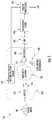
- FIG. 1schematically illustrates an interference filtering apparatus and method, according to some embodiments of the present invention.
- FIG. 2illustrates a multi-wavelength reflection-mode pulse oximetry apparatus that may be utilized in accordance with some embodiments of the present invention.
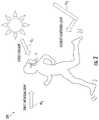
- FIG. 3illustrates various types of time-varying environmental interference.
- FIG. 4Ais a side view of a human ear with an earbud monitor, according to some embodiments of the present invention, inserted therein.
- FIG. 4Bis a front view of a human ear with an earbud monitor, according to some embodiments of the present invention, inserted therein.
- FIG. 5is a schematic illustration of how external light interference can pass through a human ear and reach an optical detector in an earbud monitor attached to the ear.
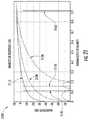
- FIG. 6is a comparison graph showing optical detector intensity vs. wavelength for direct sunlight exposure and indirect sunlight exposure caused by scattering through the ear region.
- FIG. 7illustrates a sensor module with a convex lens configuration, according to some embodiments of the present invention.
- FIG. 8illustrates a sensor module with a concave lens configuration, according to some embodiments of the present invention.
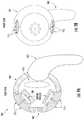
- FIG. 9Ais a rear perspective view of an earbud monitor, according to some embodiments of the present invention.
- FIG. 9Bis a front perspective view of the earbud monitor of FIG. 9A .
- FIG. 10illustrates the angling preferences for sensor modules within an earbud monitor, according to some embodiments of the present invention.
- FIG. 11illustrates an earbud monitor, according to some embodiments of the present invention, that increases physiological signal and reduces environmental noise.
- FIG. 12Ais a perspective view of a sensor module, according to some embodiments of the present invention.
- FIG. 12Bis a side view of the sensor module of FIG. 12A .
- FIG. 12Cis a top plan view of the sensor module of FIG. 12A .
- FIG. 13Ais a side view of an earbud comprising the sensor module of FIGS. 12A-12C , according to some embodiments of the present invention.
- FIG. 13Bis a front perspective view of the earbud of FIG. 13A .
- FIG. 13Cis a side perspective view of the earbud of FIG. 13A .
- FIG. 14is a bottom perspective view of a multi-detector earbud, according to some embodiments of the present invention.
- FIG. 15Ais a side perspective view of a multi-detector earbud comprising two separate optical coupling areas, according to some embodiments of the present invention.
- FIG. 15Bis a bottom plan view of the earbud of FIG. 15A .
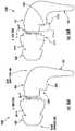
- FIG. 16Ais an exploded side view of a headphone and a replaceable/interchangeable earbud tip, according to some embodiments of the present invention.
- FIG. 16Bis an exploded side view of a headphone and a replaceable/interchangeable earbud tip, according to other embodiments of the present invention.
- FIG. 17is a rear view of the earbud tip of FIG. 16B taken along lines 17 - 17 , and illustrating at least two separate parts supporting at least two separate optical paths.
- FIG. 18is a flowchart of operations for removing environmental noise from a sensor signal, according to some embodiments of the present invention.
- FIGS. 19A and 19Bare graphs illustrating digital sampling of a detector signal, according to some embodiments of the present invention.
- FIG. 20is a schematic illustration of an interference filter, according to some embodiments of the present invention.
- FIG. 21is a graph that illustrates magnitude responses for several interference filters, according to some embodiments of the present invention.
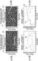
- FIGS. 22A-22Dare graphs of the processed heart rate signal output of an earbud module employing two different filter configurations, according to some embodiments of the present invention.
- FIG. 23is a perspective view of a monitoring apparatus including a sensor module of FIG. 7 or FIG. 8 , according to some embodiments of the present invention, and wherein the monitoring apparatus is adapted to fit around a wrist of a person.
- FIG. 24is a side view of the monitoring apparatus of FIG. 23 .
- FIG. 25is a plan view of the sensor module of the monitoring apparatus of FIG. 23 .
- FIG. 26is an enlarged plan view of the sensor module of the monitoring apparatus of FIG. 23 .
- FIG. 27is an enlarged side view of the sensor module of the monitoring apparatus of FIG. 23 .
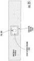
- FIG. 28illustrates the sensor module of the monitoring apparatus of FIG. 23 in contact with the skin of a subject.
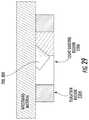
- FIG. 29is an enlarged side view of the sensor module of the monitoring apparatus of FIG. 23 , according to other embodiments of the present invention.
- the devicemay be otherwise oriented (rotated 90 degrees or at other orientations) and the spatially relative descriptors used herein interpreted accordingly.
- the terms “upwardly”, “downwardly”, “vertical”, “horizontal” and the likeare used herein for the purpose of explanation only unless specifically indicated otherwise.
- first and secondare used herein to describe various features/elements, these features/elements should not be limited by these terms. These terms are only used to distinguish one feature/element from another feature/element. Thus, a first feature/element discussed below could be termed a second feature/element, and similarly, a second feature/element discussed below could be termed a first feature/element without departing from the teachings of the present invention.
- headsetincludes any type of device or earpiece that may be attached to or near the ear (or ears) of a user and may have various configurations, without limitation. Headsets as described herein may include mono headsets (one earbud) and stereo headsets (two earbuds), earbuds, hearing aids, ear jewelry, face masks, headbands, and the like.
- modulated energyrefers to energy (e.g., optical energy, acoustic energy, ultrasonic energy, electromagnetic radiation, electrical energy, magnetic energy, mechanical energy, nuclear energy, etc.) that is emitted in pulses and/or that is emitted such that the amplitude, frequency, phase, or intensity is varied.
- a pulsed energy sourcemodulates by effectively multiplying by a waveform that is a periodic sequence of zeros and ones.
- the term “real-time”is used to describe a process of sensing, processing, or transmitting information in a time frame which is equal to or shorter than the minimum timescale at which the information is needed.
- the real-time monitoring of pulse ratemay result in a single average pulse-rate measurement every minute, averaged over 30 seconds, because an instantaneous pulse rate is often useless to the end user.
- averaged physiological and environmental informationis more relevant than instantaneous changes.
- signalsmay sometimes be processed over several seconds, or even minutes, in order to generate a “real-time” response.
- monitoringrefers to the act of measuring, quantifying, qualifying, estimating, sensing, calculating, interpolating, extrapolating, inferring, deducing, or any combination of these actions. More generally, “monitoring” refers to a way of getting information via one or more sensing elements.
- blood health monitoringincludes monitoring blood gas levels, blood hydration, and metabolite/electrolyte levels.
- physiologicalrefers to matter or energy of or from the body of a creature (e.g., humans, animals, etc.).
- the term “physiological”is intended to be used broadly, covering both physical and psychological matter and energy of or from the body of a creature.
- the term “psychological”is called-out separately to emphasize aspects of physiology that are more closely tied to conscious or subconscious brain activity rather than the activity of other organs, tissues, or cells.
- bodyrefers to the body of a subject (human or animal) who may wear a headset incorporating embodiments of the present invention.
- the human earis an ideal location for wearable health and environmental monitors.
- the earis a relatively immobile platform that does not obstruct a person's movement or vision.
- Headsets located at an earhave, for example, access to the inner-ear canal and tympanic membrane (for measuring core body temperature), muscle tissue (for monitoring muscle tension), the pinna and earlobe (for monitoring blood gas levels), the region behind the ear (for measuring skin temperature and galvanic skin response), and the internal carotid artery (for measuring cardiopulmonary functioning), etc.
- the earis also at or near the point of exposure to: environmental breathable toxicants of interest (volatile organic compounds, pollution, etc.); noise pollution experienced by the ear; and lighting conditions for the eye.
- the ear canalis naturally designed for transmitting acoustical energy, the ear provides a good location for monitoring internal sounds, such as heartbeat, breathing rate, and mouth motion.
- Wireless, Bluetooth®-enabled, and/or other personal communication headsetsmay be configured to incorporate physiological and/or environmental sensors, according to some embodiments of the present invention.
- Bluetooth® headsetsare typically lightweight, unobtrusive devices that have become widely accepted socially.
- Bluetooth® headsetsare cost effective, easy to use, and are often worn by users for most of their waking hours while attending or waiting for cell phone calls.
- Bluetooth® headsets configured according to embodiments of the present inventionare advantageous because they provide a function for the user beyond health monitoring, such as personal communication and multimedia applications, thereby encouraging user compliance.
- Exemplary physiological and environmental sensors that may be incorporated into a Bluetooth® or other type of headsetsinclude, but are not limited to accelerometers, auscultatory sensors, pressure sensors, humidity sensors, color sensors, light intensity sensors, pressure sensors, etc.
- Optical coupling into the blood vessels of the earmay vary between individuals.
- the term “coupling”refers to the interaction or communication between excitation light entering a region and the region itself.
- one form of optical couplingmay be the interaction between excitation light generated from within a light-guiding earbud and the blood vessels of the ear.
- Light guiding earbudsare described in co-pending U.S. Patent Application Publication No. 2010/0217102, which is incorporated herein by reference in its entirety.
- this interactionmay involve excitation light entering the ear region and scattering from a blood vessel in the ear such that the intensity of scattered light is proportional to blood flow within the blood vessel.
- Another form of optical couplingmay be the interaction between excitation light generated by an optical emitter within an earbud and the light-guiding region of the earbud.
- Embodiments of the present inventionare not limited to headsets that communicate wirelessly.
- headsets configured to monitor an individual's physiology and/or environmentmay be wired to a device that stores and/or processes data or there may be a combination of wired and wireless communications. In some embodiments, this information may be stored on the headset itself.
- embodiments of the present inventionare not limited to earbuds.
- the inventionmay be employed around another part of the body, such as a digit, finger, toe, limb, wrist, ankle, around the nose or earlobe, or the like.
- the inventionmay be integrated into a patch, such as a bandage that sticks on a person's body.
- FIG. 1illustrates an interference filtering apparatus/method 100 , according to some embodiments of the present invention.
- a medium 130preferably physiological material of a living subject, comprises at least one target region of interest 120 which is interrogated by energy 110 , preferably modulated energy, such as pulsed energy, generated by an energy emitter 102 .
- a pulsed driving circuit 101is used to drive at least one energy emitter 102 at one or more pulsed frequencies to interrogate at least one target region of at least one medium 130 with the pulsed energy 110 .
- the energymay be in the form of electromagnetic, acoustical, mechanical, nuclear, electrical, magnetic, thermal, or other forms of energy, but typically optical energy from the electromagnetic spectrum.
- the energy reaching the medium 130can interact with the medium to generate at least one energy response signal 111 , such as an optical scatter signal 111 between emitted optical energy 110 and the medium 130 .
- the energy response 111 caused by this interactionis detected by at least one detector 103 , configured to detect energy in the forms described above, but typically in the form of optical energy scattered from the medium 130 .
- a motion/position sensor 104may be configured to measure movement, positional changes, or inertial changes in the vicinity of the medium 130 .
- the outputs of the detector 103may be sent to at least one analog-to-digital convertor (ADC) 105 and the digitized output may be sent to at least one interference filter 106 , which is configured to remove the effects of time-varying environmental interference 140 from the signal output of the detector 103 .
- ADCanalog-to-digital convertor
- At least one motion/position sensor 104may be incorporated in the interference filtering method 100 to provide a reference signal for removing the effects of motion from the extracted energy response signal 111 to produce a desired signal 109 .
- the output of the interference filter 106may be further processed by signal extraction filter 107 to extract accurate information from the medium 130 , and this signal extraction filter 107 may utilize the output of the motion/position sensor 104 to remove motion artifacts from the desired signal (the extracted energy response signal) 109 .
- At least one signal processor(not shown) may be used to control the operations of the energy emitter 102 , detector 103 , filter 106 , and/or other components of the interference filtering method 100 .
- a monitoring apparatusis configured to be a wearable monitor for monitoring at least one physiological condition of the wearer.
- pulsed electromagnetic energy 110 from at least one electromagnetic emitter 102is directed towards at least one physiological region 130 , typically the ear region, of a subject.
- optical emittersinclude light-emitting diodes (LEDs), laser diodes (LDs), lamps, organic emitters (such as OLEDs), and the like.
- the sensor components ( 102 , 103 , and 104 )may be integrated within the ear region 120 in the form-factor of an earbud or other ear-worn form-factor such that the measurement medium 130 comprises blood vessels and/or blood flow within the ear region.
- the intensity of the pulsed optical energy 110is modulated by at least one pulsed driving circuit 101 such that the intensity is time-varying with at least two states, preferably an on state and an off state.
- This time-varying energygenerates a time-varying energy response, typically an optical interaction response, such as optical absorption, modulation, scatter, transmission, luminescence, or the like, from the physiological region 130 .
- a first optical interaction responseis obtained by at least one detector 103 , typically an optical detector, when the pulsed optical energy 110 is in the on state.
- a second energy responsein this case a second optical interaction response, is obtained by the optical detector 103 when the pulsed optical energy 110 is in the off state.
- the first and second energy response signalsare digitized by at least one ADC 105 and the digitized signals are processed via an interference filter 106 to produce a processed energy response signal that is associated with a physiological condition of the subject, wherein the filter removes time-varying environmental interference caused by an interferant, such as sunlight, ambient light, airflow, temperature, etc.
- the output of the interference filter 106is then processed by a signal extraction filter 107 to accurately extract at least one physiological property of the subject.
- a motion/position sensor 104may be configured to measure the motion/position between the medium 130 and the emitter 102 , the detector 103 , and/or the time-varying interference 140 , for example, caused by motion of the subject.
- the output signal of the motion sensor 104may provide a motion artifact reference to the signal extraction filter 107 such that the motion/position information may be selectively removed from the desired signal output.
- Incorporating a motion sensor in embodiments of the present inventionmay be particularly important because time-varying interference, such as sunlight hitting an earbud, is often modulated by motion, and monitoring and subtracting this motion from the desired output may be critical to generating an accurate physiological signal in the midst of daily life activities of the subject.
- Various forms of energy 110can be used to interrogate one or more mediums 130 and to characterize those mediums by detectors 103 configured to detect the energy responses caused by the interaction of the energy 110 with the medium 130 .
- optical energy 110can be used to interrogate a target region of skin and blood 130 to provide information regarding a physiological condition of a subject, such as a measure of blood oxygen levels of the subject by pulse oximetry.
- a physiological condition of a subjectsuch as a measure of blood oxygen levels of the subject by pulse oximetry.
- a specific example of the opto-physiological interaction between light and a physiological medium 130 comprising the skin, blood vessels, and blood of a subjectis shown in the reflective optical detection configuration 200 of FIG. 2 .
- At least one sensor module 207disposed within at least one housing configured to be attached to a body of a subject, may be in physical proximity to the skin of the subject, as shown in the reflective pulse oximetry setup 200 where reflected optical wavelengths 111 are measured, as opposed to measuring transmitted optical wavelengths.
- Optical emitter and optical detector wavelengths for pulse oximetry and photoplethysmographymay include virtually any wavelength of electromagnetic radiation, but particularly useful are UV, visible, and IR wavelengths.
- an optical source-detector assembly 201including an optical emitter 102 and optical detectors 103 , is integrated into sensor module 207 to generate optical wavelengths 110 and monitor the resulting scattered optical energy 111 .
- the optical source-detector assembly 201may contain one or more optical sources emitting one or more optical wavelengths, as well as one or more optical detectors detecting one or more optical wavelengths.
- the epidermis 212 , dermis 213 , and subcutaneous 214 layers of skin tissue of a humanare shown in FIG. 2 for reference.
- the scattered optical energy 111may be modulated in intensity by changes in physiological condition, such as: changes in blood flow in the blood vessels, changes in physical motion of the body, changes in blood metabolite levels (such as blood gases, bilirubin, glucose, lactic acid, and the like), respiration, heart rate, pulse pressure, blood pressure, and other physiological changes.
- the scattered optical energy 111may be luminescent or preferentially polarized energy from the skin, blood, blood metabolites, drugs, or other materials in the body.
- the energy response signal 111may contain information associated with at least one physiological condition of the subject.
- the energy response signal 111 collected by a wearable sensor module 207may be corrupted by time-varying environmental interference 140 ( FIG. 1 ). Moreover, the energy response signal 111 may be even further corrupted by motion of the subject in a time-varying environment. For example, the motion caused by running may cause motion with respect to the emitter 102 , detector 103 , and medium 130 (in this case tissue of the subject), and this motion may cause an unwanted signal on the detector 103 . Moreover, the time-varying environmental interference 140 ( FIG. 1 ) may be caused by, or exacerbated by, the motion of the subject.
- FIG. 3A specific example of time-varying interference in a real-world environment 300 is summarized in FIG. 3 . In FIG.
- the sensor module 207may contain at least one optical emitter 102 , at least one optical detector 103 , and at least one processor to measure heart rate, respiration rate, pulse pressure, motion, and/or other physiological conditions near the ear region 130 of the subject. These types of measurements may be achieved by detecting the optical scatter response 111 from the ear region as summarized in FIG. 2 .
- Time-varying sunlight SL 1 , SL 2 and artificial ambient light AL 1may impart time-varying optical interference 140 on the optical detector 103 embedded within the audio headset H.
- a time-varying interference signal 140 ( FIG. 1 ) from environmental lightmay impart substantial artifacts on an energy response signal 111 ( FIG. 1 ) in many real life scenarios, such as when clouds pass through the sky, when a subject runs through shadows, when a subject runs to/from an artificial light source, and/or various thereof.
- These time-varying artifactsmay be difficult to distinguish from the desired time-varying signals associated with time-varying physiological conditions.
- the interference frequencies associated with a time-varying change in shadows, or the harmonics of these interference frequenciesmay correspond with at least one signal frequency associated with footsteps, respiration, or heart rate, and the optical energy response 111 may contain convoluted information comprising interference signals and desired physiological signals.
- the aforementioned time-varying interference signal 140 ( FIG. 1 ) from direct sunlight SL 1 during joggingmay be considered to be “direct interference”, in that interfering sunlight may be detected directly by the optical detector 103 .
- the interferencemay reach the optical detector 103 indirectly, causing the same signal processing challenges as with direct interference.
- FIG. 5summarizes how external light EL 1 from the sun or other external source can pass through the ear region and reach the optical detector 103 embedded within the sensor module 207 . It may be difficult to distinguish this external light from the scattered excitation light associated with at least one physiological condition of the subject.
- a novel embodiment of the interference filtering method and apparatus 100is to employ both novel filtering methods and novel optomechanical earbud designs to: 1) remove sunlight from the desired signal response 109 ( FIG. 1 ) and 2) prevent sunlight from reaching the detector 103 in the first place.
- Embodiments of the present invention described hereinemploy at least one of these approaches, but typically both, to teach how to make a wearable monitor, such as an earbud monitor, that may provide accurate information on physiological conditions in the midst of environmental noise, such as noise from ambient light and/or sunlight.
- an optical spectrometerwas optically coupled to a light guide embedded within an earbud worn by a subject in an outdoor sunlight environment.
- the only light reaching the spectrometerwas light guided by an earbud-embedded light guide, positioned in the same basic region as the sensor module 207 shown in FIGS. 4 and 5 .
- the light guidewas guiding light from the ear region on one end towards the input of the spectrometer at the other end.
- the light guidewas covered at one end by the spectrometer and at another end by the ear of the subject, the only significant light reaching the light guide was light generated by external light EL 1 passing through the ear, as shown in FIG. 5 .
- a first spectrogramwas taken of this indirect external sunlight scattered through the ear.
- the earbudwas then removed and pointed directly at the sun, and a second spectrogram was taken of direct sunlight hitting the ear with the earbud directly facing the sun to provide a comparison graph 600 , as shown in FIG. 6 .
- the comparison graph 600shows that sunlight at wavelengths shorter than 600 nm is greatly attenuated through the subject's ear, whereas sunlight at wavelengths longer than 650 nm is minimally absorbed through the subject's ear.
- one approach to reducing the effects of sunlight on the optical response signal 111is to choose an optical emitter 102 ( FIG. 1 ) that emits light at wavelengths shorter than 600 nm and to choose an optical detector 103 ( FIG. 1 ) having an optical filter that blocks light having wavelengths longer than 600 nm or that passes light within an optical bandwidth provided by the optical emitter 102 ( FIG. 1 ).
- a 400 to 500 nm optical emitter 102may provide 400-500 nm optical excitation 110 ( FIG. 1 ) to the ear region 130 ( FIG. 1 ), and an optical detector 103 ( FIG.
- optical filterhaving a 400-500 nm optical filter may be used to detect the energy response signal 111 ( FIG. 1 ) with low interference 140 ( FIG. 1 ) from sunlight. While this method may be employed, the apparent benefits may be deceiving because the intensity of the optical scatter signal associated with physiological information may be orders of magnitude smaller than the sunlight interference—even with the combined attenuation effects of the optical filtering method and the strategic sensor module placement between the earbud housing and ear region (as shown in FIGS. 4 & 5 ).
- a better approach for attenuating the optical interference signalmay be to employ optical filters within the optical detectors 103 such that the only wavelengths passing into an optical detection window may be wavelengths that are naturally attenuated by the earth's atmosphere.
- a novel design for rejecting sunlight interferencemay incorporate at least one optical emitter that generates optical wavelengths within at least one sunlight attenuation band combined with at least one bandpass-filtered optical detector, incorporating at least one optical bandpass filter to pass only wavelengths falling within this attenuation band.
- many audio headsetsrequire openings in the material between the earbud housing and audio speaker cavity such that sound can travel freely between the tympanic membrane and the audio speaker. Sunlight may also travel between these small openings and undesirably reach the detector 103 . Sunlight scattering from unwanted openings in the plastic enclosure may scatter within the clamshells of the enclosure and reach the optical detector 103 .
- a sensor module 700 with an overmolded designmay be employed to remedy the problems associated with sunlight leaking towards the optical detector 103 .
- an overmold layer 740surrounds the components of the sensor module 700 to prevent light leakage into any spot along the periphery of the sensor module 700 .
- the overmold layer 740comprises a light-opaque material surrounding the optical emitter 102 and optical detector 103 such that the optical emitter 102 and optical detector 103 are not in direct optical communication with each other.
- the light-opaque material of the overmold layer 740may include a first aperture 740 a in communication with the optical emitter 102 , and a second aperture 740 b in communication with the optical detector 103 .
- the only device regions having access to outside lightmay be the regions of the optical emitter 102 and detector 103 , but these may be covered by at least one optical filter 710 tuned to a wavelength region of interest.
- the wavelength pass-band of an optical filter covering the emitter 102should be tuned to the emitter wavelength band so that all other light is blocked.
- the wavelength pass-band of the optical filter 710 covering the detector 103should be tuned to at least one wavelength band associated with the optical scatter 111 ( FIG. 1 ) of interest from the medium 130 ( FIG. 1 ) so that all other light is blocked.
- an optical filter for the emitter 102 and detector 103may be the same filter, such as may be the case for optical scatter 111 ( FIG. 1 ) detection by the detector 103 where all light other than the emitter light of interest may be blocked by the filter 710 .
- the optical filter 710 covering the detector 103is configured to block unwanted sunlight but still allow wavelengths from the optical emitter 102 to pass therethrough.
- the optical filter 710 over the detector 103is configured to pass wavelengths centered around 930 nm, and the optical emitter 102 is configured to emit wavelengths centered around 930 nm.
- the optical filter 710may have a surface area greater than a surface area of the optical detector 103 .
- the optical filter 710overlies the optical detector 103 such that a periphery of the optical filter 710 overlaps a periphery of the optical detector 103 , as shown in FIG. 7 and FIG. 8 .
- lenses 715may be utilized, as illustrated in FIG. 7 .
- the lenses 715may be physically separated lenses (as shown in FIGS. 7 and 8 ) or combined or conjoined lenses.
- a barrier regionmay be incorporated in the case where the lenses are combined or conjoined. Separated lenses may be isolated by at least one light opaque barrier region greater than 50 ⁇ m in thickness. Light opaque plastic, rubber, metal, or polymeric material are a few examples of good choices for the light opaque region.
- the optical lenses 715may be designed for the desired optical coupling between the skin/blood vessel region and the emitter 102 or detector 103 .
- a convex lens design(such as that of FIG. 7 ) placed over the emitter 102 may focus light onto the skin
- a concave lens design(such as that of FIG. 8 ) placed over the emitter 102 may diverge light over the skin region.
- a convex lens design placed over the detector 103may capture more light over a broader region and direct that light towards the detector 103 , whereas a concave lens may collimate light towards the detector 103 .
- the optical lenses 715may be separate from the overmold layer 740 or may be part of the overmold layer 740 .
- the overmold layer 740may be comprised of material that is transparent to light 110 ( FIG. 1 ) coming from the emitter 102 .
- the lenses 715may integral with the overmold layer 740 .
- the optical lenses 715may be comprised of different material than the overmold layer 740 , such that the lenses 715 may fit within the overmold layer 740 and be matingly engaged with the overmold layer 740 .
- the emitter 102 and detector 103may be integrated within a circuit board 720 assembly, such as a printed circuit board (PCB) assembly.
- the PCB board 720may have opposite first and second sides 720 a , 720 b , with at least one optical emitter and optical detector adjacent to each other on the first side 720 a , and with at least one secondary sensor 730 on the second side 720 b .
- the secondary sensor 730may be integrated within the PCB 720 for sensing another parameter.
- the secondary sensor 730may serve as a motion/position sensor 104 ( FIG. 1 ).
- Connections or wiring 750may be used to connect the sensor module 700 to another apparatus, connector, PCB, circuit, or the like.
- electrical wiring or fiber optic cablesmay be overmolded such that sunlight cannot pass through the interface between the wires/cables and the overmold layer 740 .
- an overmolded plastic design around the emitters 102 and detectors 103may at least partially encapsulate the emitters 102 and detectors 103 and hence at least partially isolate these devices from the environment.
- FIGS. 9A and 9Billustrate an environmentally protected earbud 900 that can incorporate overmolded sensor modules 700 , 800 , according to some embodiments of the present invention.
- at least two sensor modules 700are shown to emphasize that multiple sensor locations can be used, as long as the sensor modules 700 are configured to direct energy towards the ear and detect the energy response from the ear.
- having multiple sensor modules 700 located around the earbud housing 901may help with: a) making the environmentally protected earbud 900 work uniformly well on a variety of persons having a variety of differing ear physiology and/or b) enabling additional sensor functionality, such as the ability to sense blood gas levels, blood metabolite levels, pulse pressure, blood pressure, glucose, and a variety of other physiological metrics or analytes.
- At least one supporting arm 902may be connected to the earbud housing 901 to support a wire, electrical connections, and/or provide additional support around the ear.
- a supporting arm 902may be used to house wires or wrapped around the ear to further support the earbud housing 901 within the ear.
- an additional optical filter(e.g., 710 , FIGS. 7 and 8 ) may be utilized that serves (or also serves) as an attenuation filter, such as a “neutral density filter”, gelatin filter, opaque material, or other optical attenuation filter or filtering materials.
- an optical filter 710may serve as both an optical wavelength filter and an attenuation filter. Because sunlight is so powerful, it may be beneficial to reduce sunlight interference as much as possible, even if that means also reducing the amount of optical scatter 111 ( FIG. 1 ) of interest from the medium 130 ( FIG. 1 ). To offset this unwanted reduction in optical scatter 111 , the intensity of the optical emitter 102 may be increased to increase the ratio of physiological optical scatter 111 from blood vessels with respect to unwanted sunlight.
- the angling of the sensor modules 700 , 800 ( FIGS. 7 and 8 ) within the earbud housing 901may be designed to direct light towards the ear and detect light from the ear while rejecting as much environmental light (such as sunlight) as possible.
- angling the normal “N” of the lens 715 between the perpendicular lines “A” & “B”, where “A” is perpendicular to earth ground and “B” is parallel to earth groundwould help achieve this goal.
- the angle “ ⁇ N ” between “N” and “A” or “N” and “B”would preferably be less than 90°.
- angle “ ⁇ N ” approximating 45°may be utilized for limiting the sensor module 700 exposure to outside light while also limiting the obstruction of the audio cavity by the sensor module 700 .
- the lenses 715 described hereinmay be comprised of any material that is at least partially transparent to the wavelengths of light generated by the emitter 102 and/or the desired wavelengths of light detected by the detector 103 .
- the lenses 715are completely transparent to the light of interest, but in other embodiments of the present invention the lenses 715 may be configured to diffuse, attenuate, disperse, or redistribute light uniformly across the lens.
- a lens 715 incorporating diffusing material, placed over the emitter 102may help spread more light from the emitter more uniformly across the area of the lens such that a broader physiological region may be excited by optical radiation.
- a diffusing lens configuration placed over the detector 103may help detect light from a broader area of the body and direct that light towards the detector 103 .
- Some plastic materialscontain scattering centers or materials that tend to scatter light.
- siliconesmay be used to diffuse light in a lens.
- Partially opaque lensesmay also be used to provide diffusion or internal scattering of light within a lens.
- roughened surfaces, such as roughened plastic or glass,may encourage diffuse optical scatter without greatly attenuating the intensity of light. Other methods of creating optical diffusion or scattering in light-guiding materials such as lenses may be utilized.
- the angled emitter-detector earbud configuration 1100 of FIG. 11may be employed to maximize the collection, by the detector 103 , of the scattered light response 111 ( FIG. 1 ) related to physiological conditions and to minimize the collection of the unwanted scattered light response 111 ( FIG. 1 ) not related to physiological conditions.
- Angling the emitter 102 with respect to the detector 103can prevent unwanted light generated by the emitter, such as that scattered by the outer surface of the skin, from reaching the detector 103 .
- desired light that is guided into the blood vessels, scattered within physiological material 130 , and coupled into the detector 103may contain desired optical information associated with physiological changes. The higher the angle between the emitter an detector, the less the intensity of optical energy that may be detected by the detector 103 .
- the angle between the normal “N e ” of the optical emitter and the normal of the optical detector “N d ”is between 0° and 90°.
- the position of the emitter 102 and detector 103 as shown in FIG. 11may be reversed, providing the same effect.
- the optical emitter 102may be located near the portion of the ear having a higher density of blood vessels, such that the optical energy will be more greatly modulated by physiological conditions (such as blood flow, blood gas levels, and the like) and such that the optical energy detected by the detector 103 will be more indicative of physiological conditions and less indicative of unwanted optical scatter (such as skin reflectance) or motion-related scatter (such as motion caused by running, jogging, or talking).
- physiological conditionssuch as blood flow, blood gas levels, and the like
- unwanted optical scattersuch as skin reflectance
- motion-related scattersuch as motion caused by running, jogging, or talking
- the earbud 1100may also employ at least one earpiece fitting, or other additional mounting support, to keep the earbud in place within the ear and/or keep the sensor module 700 , 800 directed at the right angle within the ear.
- earpiece fittingsare well known in the art, such as: ear hooks, ear clips, ear pads, ear loops, concha support, headbands, and the like.
- a supportive earpiece fittinga concha support that loops around the concha-helix area of the ear, is shown in the earbud 404 of FIG. 4 .
- the earpiece fittingsupports the earbud within the ear while also placing pressure against the earbud to keep the sensor module in place, away from outside light interference.
- At least part of the earbud housing 901 ( FIG. 11 ) or sensor module 700 ( FIG. 11 )may comprise a soft material which deforms when inserted within the ear and that facilitates retention of the earbud within the ear.
- the shape of earbud housing 901 shown in FIG. 11may facilitate retention of the earbud 1100 within the ear because it may be shaped to mate or engage with the concha or outer ear canal of the ear.
- part of the earbud 1100comprises a soft material, such as soft plastic, polymer, silicone, or rubber, the material may deform when the earbud 1100 is inserted within the ear such that this part of the earbud 1100 mates or engages with the ear.
- the sensor modules of FIGS. 7 and 8may be integrated within the earbud housing 901 , such that at least a portion of the housing 901 may comprise optically transmissive material to allow light to move from the emitter 102 to the ear region or from the ear region to the detector 103 .
- the soft deforming materialmay be adjacent to the optically transmissive material or may comprise at least part of the optically transmissive material itself.
- the lenses 715 of FIG. 9may be comprised of optically transparent material that is also soft, such as silicone or transparent plastic, polymer, rubber, or the like.
- a second layer of soft, yet transparent, materialmay cover the lenses 715 .
- FIGS. 12A-12CAn exemplary overmolding configuration of a sensor module 1201 is illustrated in FIGS. 12A-12C .
- the sensor module 1201is shown without an emitter, detector, or lenses, but rather with recesses/apertures 1202 showing where lenses may be located.
- Exemplary dimensionsare also presented in FIG. 12 . In some embodiments of the present invention, dimensions are on the order of millimeters or less, such that the sensor module 1201 can fit within a small-sized earbud without obstructing, or minimally obstructing, the audio cavity.
- an emitter and detector to be used with the sensor module 1201can be arranged in a line that is parallel with the antitragus. This arrangement is illustrated in FIGS. 13A-13C .
- embodiments of the present inventionare not limited to any particular set of dimensions or to any shape or configuration.
- FIG. 14illustrates a multi-detector earbud 1400 , similar to the earbud 1300 of FIGS. 13A-13C , but where two separate optical detectors (not shown) are covered by two separate optical lenses 715 .
- An optical emitter 102is located between the two optical lenses 715 .
- Employing multiple optical detectorsmay provide several benefits: 1) more scattered light collection, providing stronger signal strength, 2) additional information on scattered light collection for improving physiological assessments, 3) light collection at different wavelengths for measuring blood constituents, pulse pressure, skin, color, and the like, and 4) other benefits. For example, light entering the ear may scatter throughout several blood vessels, and without multiple detectors, signal information may be lost.
- blood flow scatter collected from the front of the earmay be more indicative of blood flow through the carotid artery system, whereas blood flow scatter collected from the back of the ear may be more indicative of the capillary or venous system.
- the difference between these two signalsmay be processed with algorithms to generate an assessment of pulse pressure, blood pressure, cardiac output, and the like.
- collecting light at different wavelengths, and processing these signals collectivelycan be used to generate assessments of blood gas levels, such as blood oxygen (SpO 2 ) and carbon dioxide (SpCO 2 ), blood hemoglobin types and levels, or other blood constituents and their respective concentration levels.
- Multiple wavelengthsmay be generated by a signal multiwavelength optical emitter, multiple optical emitters, optically filtered optical emitters, or the like. In such case, multiple optical emitters 102 may be located between the two optical filters 715 .
- FIGS. 15A-15Bshow a multi-detector earbud 1500 , where two separate optical detectors 103 are covered by two separate optical lenses, at least one optical emitter is covered by at least one optical lens, and where the emitter 102 and detector 103 configuration is oriented perpendicularly to the antitragus (as that shown in FIG. 11 ).
- the optical detectors 103 , emitters 102 , and lensesare not readily visible as they are surrounded, at least in part, by an optical coupling area 1510 .
- the lensesmay cover each separate emitter 102 and detector 103 as shown in FIGS. 7 and 8 . Note that in this configuration, the emitter-detector module 700 , 800 of FIGS.
- FIGS. 15A and 15BAnother feature of the earbud 1500 of FIGS. 15A and 15B is that an optical coupling area 1510 is located on top of the optical emitter 102 and surrounding (but not covering) the optical detector 103 . This optical coupling area 1510 may help diffuse, scatter, and/or guide light from the optical emitter to couple with a broader area of the ear region.
- Having a broader coupling areamay help excite more regions of the ear with optical energy 110 ( FIG. 1 ) and reduce the chance that the optical energy may miss important blood vessels, which may be located in different regions for different persons.
- a designmay promote a more universal design for a biometric earbud.
- the optical energy 110 from the optical emitter(s) 102may miss blood vessels in different persons due to physiological differences that may exist between different people.
- the optical coupling area 1510may be configured to cover the optical detector 103 area and not the optical emitter 102 area, such that more light is guided from different regions of the ear and coupled into the detector 103 .
- a plurality of optical diffusion areasmay be configured to cover the emitter 102 and detector 103 separately.
- the material selection for the optical coupling region 1510may be any type of optically transmissive material.
- a plastic, rubber, silicone, or other soft, moldable materialmay be used.
- the materialmay intentionally contain scattering centers or may contain partially opaque regions to promote optical scatter and generate a uniform, diffuse optical beam across the optical coupling area 1510 .
- the materialmay be roughened, as with roughened plastic or glass, to generate scattering centers.
- FIGS. 16A-16Billustrate an exemplary headphone 1600 having a replaceable/interchangeable earbud tip 1601 with an outer surface 1601 a and an inner surface 1601 b .
- An interchangeable tip 1601can provide the benefit of allowing larger or smaller tips on the end of the earbud housing 901 to accommodate larger or smaller ears.
- a typical commercially available headphone structuremay look like the embodiment illustrated in FIG. 16A .
- an optical sensor module 700is integrated into the bottom of the headphone housing 901 , in the region near the antitragus, in a form-fitted shape 1610 designed to make contact with the antitragus region.
- thismay increase the size of the housing by a few millimeters in multiple dimensions.
- the interchangeable earbud tip 1601may be modified with a form-mating region 1612 to mate with the form-fitted region 1610 and thus accommodate the change in size imposed by the optical sensor module 700 .
- optical coupling and waveguidingare incorporated into a headphone.
- at least one emitter (not shown) and at least one detector (not shown)may be integrated into a sensor module and stationed within an earbud housing 901 of the headphone 1600 of FIG. 16A without the addition of a form-fitted shape 1610 ( FIG. 16B ) or mating region 1612 ( FIG. 16B ).
- Optical excitation of the ear regioncan be generated by guiding light from an emitter to an interchangeable earbud tip 1601 and into the ear region or by guiding scattered light from the ear region into the earbud tip 1601 and into an optical detector.
- the optical emittermay be positioned in the earbud face 1605 region to direct light towards the earbud tip 1601 .
- the optical detectoris positioned in the earbud bottom region 1606 ( FIG. 16A ) to receive light from the bottom of the ear.
- the detectormay be located in the front earbud face region 1605 ( FIG. 16A ) to receive light from the earbud tip 1601 .
- the optical emitteris positioned within the earbud bottom region 1606 ( FIG. 16A ).
- the earbud materialis made of at least partially transparent materials, which are transparent to the wavelength of interest.
- an earbud material having a higher index of refraction than airmay be used so that more light is guided along the earbud tip 1601 and less light is scattered away from the earbud tip 1601 .
- intermediate regions between the earbud face 1605 and the earbud tip 1601may be utilized in order to promote optical coupling between the two regions.
- a lens (not shown) or other light guiding regionmay be placed over the emitters or detectors to promote this optical coupling.
- emitter(s) and detector(s)may both be positioned in the earbud face 1605 region to direct light towards the earbud tip 1601 .
- the earbud tip 1601may help: 1) direct light from the emitter to the ear region and 2) direct light from the ear region to the detector.
- optical scatter interference associated with light from an emitter bouncing around in, around, and about the earbud tip 1601may convolute a desired optical scatter signal (e.g., 111 , FIG. 1 ) associated with physiological information (such as blood flow in the ear region).
- the earbud tip 1601may include at least two separate parts, as shown in FIG. 17 .
- the earbud tip 1601 illustrated in FIG. 17is separated into two parts (an emitter coupling part and a detector coupling part) by an optical barrier 1710 that extends through the earbud tip 1601 between the outer surface 1601 a and the inner surface 1601 b , as illustrated, with the emitter coupling part coupled to the optical emitter and the detector coupling part coupled to the optical detector.
- Each partmay support at least one separate optical path isolated by at least one optical barrier 1710 . For example, one part may direct light from the emitter to the ear region and another part may direct light to the detector from the ear region.
- the optical barrier 1710may be any material that is partially or completely opaque to the light wavelength of interest or any interface which reduces light transmission or communication between the two earbud tip parts.
- the earbud tip 1601may be molded from two (or more) separate materials (plastic, rubber, silicone, and the like) separated by: 1) an opaque material (plastic, rubber, silicone, paint, and the like) or 2) at least one interface between the two (or more) separate materials.
- the interfacemay be as simple as the natural interface between the two separate materials or as complex as by specially treating the interface by heat, light, abrasion, dissolving, chemical application, or the like.
- a roughened interfacemay help scatter light away from the interface and help keep the optical paths isolated within each respective part.
- a multi-part earbud tip designmay require a mating region 1612 to help align the earbud coupling part and detector coupling part with the emitter(s) and detector(s) respectively.
- this designshould not be limited to the two earbud tip parts (the emitter coupling part and detector coupling part) shown in FIG. 17 .
- multiple earbud tip partsmay be employed to direct light from multiple separate emitters and/or multiple separate detectors located along the earbud housing 1901 .
- multiple separate materialsmay be used in each part, such that each part may provide different optical filtering or conditioning properties. Such a design may be particularly important for multiwavelength spectroscopy of the ear region.
- An exemplary filterprocesses samples 1910 , the off/on samples 1920 / 1930 respectively, taken from a digitized physiological sensor signal 1911 generated by a detector (e.g., 103 , FIG. 1 ) as shown in FIGS. 19A-19B .
- a pulsed emittere.g., 102 , FIG. 1
- a pulsed emittergenerates a pulsed beam of light such that some samples 1920 represent signal 1911 from a detector with the emitter turned off and other samples 1930 represent signal 1911 from the detector with the emitter turned on.
- Both types of samples 1920 and 1930may contain environmental noise from environmental interferants, but only emitter-on samples 1930 contain physiological information generated by the emitter energy.
- the digitized samples taken from detector signal 1911provided by an ADC (e.g., 105 , FIG. 1 ), are processed by an interference filter (e.g., 106 , FIG. 1 ) and the output of the interference filter may be directed for further processing (represented by 107 , FIG. 1 ).
- FIG. 18is a flow chart of operations for removing environmental noise from a sensor signal via an interference filter, according to some embodiments of the present invention.
- At Block 1800at least one ADC sample is read when the emitter is on.
- At Block 1802at least one ADC sample is read when the emitter is off.
- relevant on/off samplesare input to an interference filter.
- At Block 1806at least one sample from the interference filter is output for further processing.
- An interference filter(e.g., 106 , FIG. 1 ) utilized according to embodiments of the present invention, may vary in nature and complexity.
- an interference filtermay subtract temporally neighboring emitter-off samples 1920 ( FIG. 19A ) from temporally neighboring emitter-on samples 1930 ( FIG. 19A ) and output a “subtraction” signal for further processing.
- the subtractionmay involve subtracting temporally neighboring on/off samples, averaging temporally neighboring on samples and averaging temporally neighboring off samples and then subtracting the average off samples from the average on samples, or by other approaches to subtracting off signals 1920 from on signals 1930 .
- the sampling frequencymay need to be much higher than the Nyquist frequency required for characterizing the signal in a stationary environment.
- an interference filtere.g., 106 , FIG. 1
- sunlight interferencee.g., SL 1 , SL 2 , FIG. 3
- a person running through alternating shadowsmay generate a sunlight interference frequency greater than 10 Hz.
- Samples that are temporally neighboringmay be averaged in this case to help remove noise associated with unintended transients.
- the off samples 1920 ( FIGS. 19A, 19B ) that come before, and/or after, a given on sample 1930FIGS. 19A, 19B
- a given on sample 1930FIGS. 19A, 19B
- this final resultmay be passed along for further processing.
- a batch of datamay be defined to consist of: 1) a set number of on/off optical detector samples, for instance 6 interleaved on/off samples, 2) a set number of motion sensor samples, for instance 3 samples (one for each on/off optical sample), and 3) a time delay.
- the time delaymay be adjusted to generate the desired batch rate or batch frequency.
- the 6 on/off optical samplesmay be input to a multi-tap filter, for instance an M-tap weighted sum filter, and the output may be defined as 1 output per batch for the interference filter. If the optical on/off samples are extended to fill the whole batch period by “N” samples, then the decimation factor is “N”, and the effective sample rate is N*batch rate.
- the parameters for adjustment in this filtermay then be N and M, where M is the number of taps in the filter.
- the batch ratemay be chosen to avoid aliasing of interfering harmonics from the desired physical condition monitored, such as the heart rate. For example, batch rate may be chosen as 10*HRmax, where HRmax is the maximum heart rate to be measured.
- the batch ratemay dominate the MIPS (million instructions per second) used by a signal processor, such as a DSP (digital signal processor), since it affects the spectral transform of the desired output signal.
- a signal processorsuch as a DSP (digital signal processor
- the modulated light 110may be pulsed completely on or completely off, or it may be pulsed partially on or partially off.
- the modulated lightmay be sinusoidal.
- a benefit of complete on/off pulsingis that it may better-facilitate the signal processing methodologies outlined herein for attenuating environmental noise and motion-coupled environmental noise from one or more output signals.
- a finite impulse response (FIR) version of an interference filteris presented in FIG. 20 and identified as 2000 .
- the illustrated interference filter 2000employs a delay of “n” samples according to Z ⁇ n . Coefficients in the filter “b n ” allow multi-tap filtering. Pulsing an emitter (e.g., 102 , FIG. 1 ) and selectively sampling on/off signals, as described herein, may modulate the physiological signal to a higher frequency. Thus, the output y(n) of the interference filter 2000 may be decimated to demodulate the output back into the baseband.
- Examples of filters embodying the interference filter 2000 , for removing sunlight interference from a PPG signal 1911 ( FIGS. 19A, 19B ) to extract heart rate, according to embodiments of the present invention,are illustrated in the plot 2100 of FIG. 21 .
- Also shown in FIG. 21is a representation of the modulated heart rate 2160 modulated by the emitter on/off sample rate, the demodulated heart rate 2140 demodulated by decimation, and the interference frequency associated with dynamic sunlight noise 2150 .
- a filter 2120 for subtracting the temporally neighboring off-samples 1920 , coming before and after a given on-sample 1930may employ coefficients of [ ⁇ 0.05 1 ⁇ 0.5].
- a filter 2130 using multiple on/off samplesmay employ coefficients of [ ⁇ 0.07 0.3 ⁇ 0.6 0.6 ⁇ 0.3 0.07].
- interference filter 2000may reject more unwanted sunlight than less complex filters. Because the dominant sunlight noise frequencies 2150 may be located at lower frequencies, and because the modulated heart rate signal frequency 2160 may be located at a much higher frequency, most or all of the sunlight noise 2150 may be rejected by the interference filter 2130 . Then through demodulation in further-processing (e.g., 107 , FIG. 1 ), the heart rate signal may be returned to the baseband so that real-time heart rate may be extracted.
- An interference filtering methodmay employ a motion/position sensor (e.g., 104 , FIG. 1 ) to further remove interference from a desired physiological signal (e.g., 109 , FIG. 1 ).
- a motion/position sensore.g., 104 , FIG. 1
- a desired physiological signale.g., 109 , FIG. 1
- a desired physiological signale.g., 109 , FIG. 1
- a desired physiological signale.g., 109 , FIG. 1
- a desired physiological signale.g., 109 , FIG. 1
- a desired physiological signale.g., 109 , FIG. 1
- a desired physiological signale.g., 109 , FIG. 1
- a desired physiological signale.g., 109 , FIG. 1
- an earbud sensor modulee.g., 207 , FIG. 2
- outdoor sunlightmay more strongly illuminate an ear and detector 103 in the sensor module
- a technique for removing sunlight interferencemay effectively remove the baseband frequencies of this interference, harmonics caused by motion-induced sunlight noise may dominate the digitized signal near the frequencies of the modulated desired information (e.g., 2160 , FIG. 21 ).
- the step rate of a person running or joggingmay be the strongest component of this interference.
- the interference signalmay be a convolution of motion-coupled-sunlight changes in time.
- a technique for removing sunlight interferenceutilizes a motion or position sensor (e.g., 104 , FIG.
- the step ratemay be measured as the peak frequency in the spectrum of the signal coming from motion/position sensor 104 or as the frequency of the spectral peak of the signal coming from the motion/position sensor 104 .
- the processed spectrummay employ differentiation or integration to generate a processed motion/position signal, and the peak frequency of this processed spectrum may be more indicative of the step rate. Harmonics and aliased harmonics of the step rate may determine the frequencies of interference to ignore in the desired-information spectrum.
- the emitter pulse rate minus eight times the step ratemay be the frequency of strong interference in the frequency space of the modulated heart rate (e.g., 2160 , FIG. 21 ), and frequencies within a pre-determined range may be set to zero in the desired-information spectrum.
- a motion/position sensorutilized in accordance with some embodiments of the present invention may come from a broad range of sensors: inertial sensor, accelerometer, pedometer, gyroscope, microelectromechanical sensor, capacitive sensor, electrical sensor, inductive sensor, optical motion sensor, or the like. This is because many types of sensors may be either intentionally or unintentionally sensitive to motion and/or position.
- a sensor 104FIG. 1
- processing algorithmare utilized that can identify motion signals from physiological, environmental, or other signals not directly associated with motion.
- motion-related signalsmay be identified from physiological-related signals by processing signals from the multiple detectors using an algorithm, such as a spectral algorithm.
- An example of a spectral processing algorithm for identifying motion-related signalsis to generate a spectral representation of all signals in all detectors (e.g., 102 , FIG. 1 ), identify key frequencies in each signal, and subtract, reduce, or remove all frequencies in common with each detector output. This type of filtering technique may work well because physiological signals may generate similar spectral peaks for all detectors (e.g., 102 , FIG. 1 ) but motion signals may generate dissimilar spectral peaks in at least one detector (e.g., 103 , FIG. 1 ).
- Another example of processing the detectors (e.g., 102 , FIG. 1 ) to identify and remove motion-related signalsis to position at least one detector in a location that does not “see” optical scatter (e.g., 111 , FIG. 1 ) from the body/ear region but instead sees optical scatter from the earbud housing (e.g., 901 , FIGS. 9A, 9B ) or other material that may move in synchronization with the body.
- the secondary sensor 730FIG. 7
- FIGS. 22A-22Dare graphs of a processed heart rate signal output 109 of an earbud module (e.g., earbud module 207 , 700 , FIGS. 2, 7 ) employing two different filter configurations, according to some embodiments of the present invention.
- the graphs illustrated in FIGS. 22A-22Dwere generated from data collected from a user wearing an earbud (e.g., 404 , FIGS. 4A, 4B ) during an outdoor run.
- FIGS. 22A and 22Cshow relative spectrograms of frequency vs. time, where the strongest spectral signals show the brightest relative intensities.
- FIGS. 22B and 22Dshow the estimates of step rate 2210 and heart rate 2220 following further processing 107 to extract the desired frequencies of interest.
- FIG. 22Ashows the spectrogram of the digitized sensor output from an optical detector (e.g., 103 , FIG. 1 ) following the ADC process (e.g., 105 , FIG. 1 ) without employing an interference filter (e.g., 106 , FIG. 1 ).
- FIG. 22Cshows the spectrogram of the same digitized sensor output of FIG. 22A following signal processing via the interference filter 2130 of FIG. 21 .
- FIG. 22Ashows a great deal of broadband noise from sunlight, the strongest signal appears to be the step rate signal 2210 , and the heart rate spectrum 2220 appears very faint with respect to the step rate signal. In contrast, FIG.
- FIG. 22Cshows substantially less broadband noise from sunlight, the strongest signal appears to be the heart rate signal 2220 , and the step rate signal 2210 appears very faint with respect to the heart rate signal.
- the heart rate 2220 and step rate 2210may be extracted, as shown in FIGS. 22B and 22D .
- FIG. 22Bshows that the estimated heart rate signal 2200 is incorrect and does not match that of the spectrogram illustrated in FIG. 22A .
- FIG. 22Dshows that the estimated heart rate signal 2200 is correct and does match that of the spectrogram illustrated in FIG. 22C .
- the advanced interference filter 2130is able to remove enough unwanted sunlight interference that the heart rate spectrum may be more easily extracted by spectral algorithms 107 ( FIG. 1 ) designed to pick out the strongest frequency as heart rate.
- Monitoring apparatuscan be adapted to fit around various parts of the body, such as an arm, leg, neck, etc.
- monitoring apparatuscan be implemented as a substrate, such as a wristband, armband, legband, neckband, waistband, ankleband, footband, handband, ringband, headband, or the like.
- the substratemay be flexible and may be configured to surround all or a portion of a body of a subject.
- the substratemay be configured to be attached to a body of a subject adhesively, similar to a bandage.
- the location of a sensor module(e.g., 700 , 800 ) may be virtually any place along the skin of a subject; however, better PPG results may be obtained when a sensor module is placed along an major artery.
- the wristband 2300houses a power source, circuitry, a sensor module, and electronics as described above with respect to the various earbud embodiments.
- a sensor module 700 , 800is positioned on the inside surface 2302 of the wristband 2300 .
- the sensor module 700 , 800may include an isolation region 2304 that is configured to keep the sensor module 700 , 800 stable with respect to the subject's wrist during use so as to reduce motion artifacts.
- the isolation regionmay be constructed out of any sturdy material, but for comfort, a foamy and/or flexible sturdy material may be utilized.
- the isolation region 2304may further shield against environmental interference such as sunlight, external temperature, wind, and the like.
- a light guiding region 2306may surround or partially surround the sensor module 700 , 800 and/or isolation region 2304 , as illustrated in FIGS. 24-27 .
- the light guiding region 2306surrounds the sensor module 700 , 800 .
- the light guiding region 2306partially surrounds the sensor module 700 , 800 .
- the light guiding region 2306helps direct light to and/or from the sensor module 700 , 800 and a blood flow region within the body part.
- the light guiding region 2306may be a reflector, such as a metal, metallic alloy, mylar, mica, reflective plastic, reflective textile, or the like.
- the light guiding region 2306may be a transparent light guide, such as transparent silicone, polymers, rubbers, textiles, glass, epoxies, glues, or the like.
- the sensor module 700 , 800is at least partially exposed.
- the sensor module 700 , 800may be completely covered.
- the sensor module 700 , 800may be tilted with respect to a body part region (e.g., the wrist area) of a subject.
- the sensor module 700 , 800is tilted towards the wrist (away from the upper arm).
- the embodiment illustrated in FIG. 28has a light guiding region 2306 with a different configuration from the light guiding region 2306 illustrated in the embodiment of FIG. 29 .
- the tilting of the sensor module 700 , 800serves at least the following functions: 1) protection from sunlight and 2) improvement of coupling between light from the sensor module 700 , 800 and blood flow in the body part (i.e., wrist area).
- Sunlight immunitymay be improved in this fashion because a human's wrist is typically pointed away from sunlight, and so pointing the sensor module down along the arm may help prevent environmental (i.e., sunlight) interference. Also, pointing the sensor module 700 , 800 towards the wrist may increase the surface area of blood flow exposed to the sensor module 700 , 800 , thus increasing the blood flow signal intensity for PPG and the like.
- the processing of signals generated by the sensor module 700 , 800 in the wristband embodiments of FIGS. 23-29may be similar or identical to that described above with respect to the earbud embodiments.
Landscapes
- Health & Medical Sciences (AREA)
- Life Sciences & Earth Sciences (AREA)
- Engineering & Computer Science (AREA)
- Physics & Mathematics (AREA)
- Biomedical Technology (AREA)
- Public Health (AREA)
- General Health & Medical Sciences (AREA)
- Medical Informatics (AREA)
- Molecular Biology (AREA)
- Veterinary Medicine (AREA)
- Animal Behavior & Ethology (AREA)
- Surgery (AREA)
- Biophysics (AREA)
- Pathology (AREA)
- Heart & Thoracic Surgery (AREA)
- Signal Processing (AREA)
- Physiology (AREA)
- Psychiatry (AREA)
- Artificial Intelligence (AREA)
- Computer Vision & Pattern Recognition (AREA)
- Otolaryngology (AREA)
- Cardiology (AREA)
- Optics & Photonics (AREA)
- Spectroscopy & Molecular Physics (AREA)
- Hematology (AREA)
- Primary Health Care (AREA)
- Epidemiology (AREA)
- General Business, Economics & Management (AREA)
- Business, Economics & Management (AREA)
- Measuring Pulse, Heart Rate, Blood Pressure Or Blood Flow (AREA)
- Measurement Of The Respiration, Hearing Ability, Form, And Blood Characteristics Of Living Organisms (AREA)
- Measuring And Recording Apparatus For Diagnosis (AREA)
- Pulmonology (AREA)
Abstract
Description
Claims (17)
Priority Applications (1)
| Application Number | Priority Date | Filing Date | Title |
|---|---|---|---|
| US15/262,528US10827979B2 (en) | 2011-01-27 | 2016-09-12 | Wearable monitoring device |
Applications Claiming Priority (4)
| Application Number | Priority Date | Filing Date | Title |
|---|---|---|---|
| US201161436664P | 2011-01-27 | 2011-01-27 | |
| US13/358,102US8888701B2 (en) | 2011-01-27 | 2012-01-25 | Apparatus and methods for monitoring physiological data during environmental interference |
| US14/511,692US20150031967A1 (en) | 2011-01-27 | 2014-10-10 | Apparatus and Methods for Monitoring Physiological Data During Environmental Interference |
| US15/262,528US10827979B2 (en) | 2011-01-27 | 2016-09-12 | Wearable monitoring device |
Related Parent Applications (1)
| Application Number | Title | Priority Date | Filing Date |
|---|---|---|---|
| US14/511,692ContinuationUS20150031967A1 (en) | 2011-01-27 | 2014-10-10 | Apparatus and Methods for Monitoring Physiological Data During Environmental Interference |
Publications (2)
| Publication Number | Publication Date |
|---|---|
| US20160374621A1 US20160374621A1 (en) | 2016-12-29 |
| US10827979B2true US10827979B2 (en) | 2020-11-10 |
Family
ID=46577891
Family Applications (5)
| Application Number | Title | Priority Date | Filing Date |
|---|---|---|---|
| US13/358,102Active2032-10-10US8888701B2 (en) | 2011-01-27 | 2012-01-25 | Apparatus and methods for monitoring physiological data during environmental interference |
| US14/511,692AbandonedUS20150031967A1 (en) | 2011-01-27 | 2014-10-10 | Apparatus and Methods for Monitoring Physiological Data During Environmental Interference |
| US15/262,528Active2032-03-11US10827979B2 (en) | 2011-01-27 | 2016-09-12 | Wearable monitoring device |
| US15/787,574AbandonedUS20180055450A1 (en) | 2011-01-27 | 2017-10-18 | Wearable monitoring device |
| US16/169,375Active2034-05-18US11324445B2 (en) | 2011-01-27 | 2018-10-24 | Headsets with angled sensor modules |
Family Applications Before (2)
| Application Number | Title | Priority Date | Filing Date |
|---|---|---|---|
| US13/358,102Active2032-10-10US8888701B2 (en) | 2011-01-27 | 2012-01-25 | Apparatus and methods for monitoring physiological data during environmental interference |
| US14/511,692AbandonedUS20150031967A1 (en) | 2011-01-27 | 2014-10-10 | Apparatus and Methods for Monitoring Physiological Data During Environmental Interference |
Family Applications After (2)
| Application Number | Title | Priority Date | Filing Date |
|---|---|---|---|
| US15/787,574AbandonedUS20180055450A1 (en) | 2011-01-27 | 2017-10-18 | Wearable monitoring device |
| US16/169,375Active2034-05-18US11324445B2 (en) | 2011-01-27 | 2018-10-24 | Headsets with angled sensor modules |
Country Status (3)
| Country | Link |
|---|---|
| US (5) | US8888701B2 (en) |
| EP (2) | EP3248539A1 (en) |
| WO (1) | WO2012103273A2 (en) |
Cited By (5)
| Publication number | Priority date | Publication date | Assignee | Title |
|---|---|---|---|---|
| US20220022751A1 (en)* | 2014-09-18 | 2022-01-27 | Masimo Semiconductor, Inc. | Enhanced visible near-infrared photodiode and non-invasive physiological sensor |
| US11337609B2 (en)* | 2019-01-25 | 2022-05-24 | Samsung Electronics Co., Ltd. | Texture interface for measuring bio-signal and bio-signal measuring apparatus including the same |
| US12013725B2 (en) | 2013-11-29 | 2024-06-18 | Ouraring, Inc. | Wearable computing device |
| US20240259721A1 (en)* | 2014-04-21 | 2024-08-01 | Apple Inc. | Wireless earphone |
| US12443229B2 (en) | 2025-02-26 | 2025-10-14 | Ouraring Inc. | Wearable computing device |
Families Citing this family (216)
| Publication number | Priority date | Publication date | Assignee | Title |
|---|---|---|---|---|
| US6697658B2 (en) | 2001-07-02 | 2004-02-24 | Masimo Corporation | Low power pulse oximeter |
| US8401212B2 (en) | 2007-10-12 | 2013-03-19 | Earlens Corporation | Multifunction system and method for integrated hearing and communication with noise cancellation and feedback management |
| US7647083B2 (en) | 2005-03-01 | 2010-01-12 | Masimo Laboratories, Inc. | Multiple wavelength sensor equalization |
| US8652040B2 (en) | 2006-12-19 | 2014-02-18 | Valencell, Inc. | Telemetric apparatus for health and environmental monitoring |
| US8157730B2 (en) | 2006-12-19 | 2012-04-17 | Valencell, Inc. | Physiological and environmental monitoring systems and methods |
| US8251903B2 (en) | 2007-10-25 | 2012-08-28 | Valencell, Inc. | Noninvasive physiological analysis using excitation-sensor modules and related devices and methods |
| WO2009155358A1 (en) | 2008-06-17 | 2009-12-23 | Earlens Corporation | Optical electro-mechanical hearing devices with separate power and signal components |
| US8621724B2 (en) | 2008-06-27 | 2014-01-07 | Snik Llc | Headset cord holder |
| US10652661B2 (en) | 2008-06-27 | 2020-05-12 | Snik, LLC | Headset cord holder |
| US20100004518A1 (en) | 2008-07-03 | 2010-01-07 | Masimo Laboratories, Inc. | Heat sink for noninvasive medical sensor |
| US8515509B2 (en) | 2008-08-04 | 2013-08-20 | Cercacor Laboratories, Inc. | Multi-stream emitter for noninvasive measurement of blood constituents |
| BRPI0919266A2 (en) | 2008-09-22 | 2017-05-30 | SoundBeam LLC | device and method for transmitting an audio signal to a user, methods for manufacturing a device for transmitting an audio signal to the user, and for providing an audio device for a user, and device and method for transmitting a sound for a user. user having a tympanic membrane |
| US8788002B2 (en) | 2009-02-25 | 2014-07-22 | Valencell, Inc. | Light-guiding devices and monitoring devices incorporating same |
| US9750462B2 (en) | 2009-02-25 | 2017-09-05 | Valencell, Inc. | Monitoring apparatus and methods for measuring physiological and/or environmental conditions |
| EP3127476A1 (en) | 2009-02-25 | 2017-02-08 | Valencell, Inc. | Light-guiding devices and monitoring devices incorporating same |
| JP2012530552A (en) | 2009-06-18 | 2012-12-06 | サウンドビーム エルエルシー | Optically coupled cochlear implant system and method |
| US10555100B2 (en) | 2009-06-22 | 2020-02-04 | Earlens Corporation | Round window coupled hearing systems and methods |
| EP2656639B1 (en) | 2010-12-20 | 2020-05-13 | Earlens Corporation | Anatomically customized ear canal hearing apparatus |
| US8888701B2 (en) | 2011-01-27 | 2014-11-18 | Valencell, Inc. | Apparatus and methods for monitoring physiological data during environmental interference |
| US20130144130A1 (en)* | 2011-02-01 | 2013-06-06 | Zephyr Technology Corporation | System method and device for monitoring a person's vital signs |
| KR20140054014A (en) | 2011-07-08 | 2014-05-08 | 글로벌 뉴트리션 앤드 헬스 인코포레이티드 | Personalized nutrition and wellness aids |
| WO2013016007A2 (en) | 2011-07-25 | 2013-01-31 | Valencell, Inc. | Apparatus and methods for estimating time-state physiological parameters |
| WO2013019494A2 (en) | 2011-08-02 | 2013-02-07 | Valencell, Inc. | Systems and methods for variable filter adjustment by heart rate metric feedback |
| WO2013109389A1 (en) | 2012-01-16 | 2013-07-25 | Valencell, Inc. | Physiological metric estimation rise and fall limiting |
| JP6116017B2 (en) | 2012-01-16 | 2017-04-19 | ヴァレンセル, インコーポレイテッドValencell, Inc. | Reduction of physiological measurement error by inertia rhythm |
| US10524038B2 (en) | 2012-02-22 | 2019-12-31 | Snik Llc | Magnetic earphones holder |
| US9769556B2 (en) | 2012-02-22 | 2017-09-19 | Snik Llc | Magnetic earphones holder including receiving external ambient audio and transmitting to the earphones |
| JP6374378B2 (en) | 2012-05-11 | 2018-08-15 | ハーマン インターナショナル インダストリーズ インコーポレイテッド | Earphones and small earphones with physiological sensors |
| US10314492B2 (en) | 2013-05-23 | 2019-06-11 | Medibotics Llc | Wearable spectroscopic sensor to measure food consumption based on interaction between light and the human body |
| US9582035B2 (en) | 2014-02-25 | 2017-02-28 | Medibotics Llc | Wearable computing devices and methods for the wrist and/or forearm |
| US10772559B2 (en) | 2012-06-14 | 2020-09-15 | Medibotics Llc | Wearable food consumption monitor |
| US8948832B2 (en)* | 2012-06-22 | 2015-02-03 | Fitbit, Inc. | Wearable heart rate monitor |
| US9081542B2 (en)* | 2012-08-28 | 2015-07-14 | Google Technology Holdings LLC | Systems and methods for a wearable touch-sensitive device |
| US20140081098A1 (en)* | 2012-09-14 | 2014-03-20 | Nellcor Puritan Bennett Llc | Sensor system |
| WO2014045774A1 (en)* | 2012-09-24 | 2014-03-27 | 株式会社村田製作所 | Biosensor and method for manufacturing biosensor |
| CN111464901B (en)* | 2012-12-14 | 2022-02-11 | 瓦伦赛尔公司 | Light guide and monitoring device comprising a light guide |
| US10660526B2 (en) | 2012-12-31 | 2020-05-26 | Omni Medsci, Inc. | Near-infrared time-of-flight imaging using laser diodes with Bragg reflectors |
| CA2895982A1 (en) | 2012-12-31 | 2014-07-03 | Omni Medsci, Inc. | Short-wave infrared super-continuum lasers for early detection of dental caries |
| US9500634B2 (en) | 2012-12-31 | 2016-11-22 | Omni Medsci, Inc. | Short-wave infrared super-continuum lasers for natural gas leak detection, exploration, and other active remote sensing applications |
| WO2014143276A2 (en) | 2012-12-31 | 2014-09-18 | Omni Medsci, Inc. | Short-wave infrared super-continuum lasers for natural gas leak detection, exploration, and other active remote sensing applications |
| US12193790B2 (en) | 2012-12-31 | 2025-01-14 | Omni Medsci, Inc. | Wearable devices comprising semiconductor diode light sources with improved signal-to-noise ratio |
| EP2938259A4 (en) | 2012-12-31 | 2016-08-17 | Omni Medsci Inc | Near-infrared lasers for non-invasive monitoring of glucose, ketones, hba1c, and other blood constituents |
| WO2014109982A2 (en) | 2013-01-09 | 2014-07-17 | Valencell Inc. | Cadence detection based on inertial harmonics |
| ITMI20130104A1 (en)* | 2013-01-24 | 2014-07-25 | Empatica Srl | DEVICE, SYSTEM AND METHOD FOR THE DETECTION AND TREATMENT OF HEART SIGNALS |
| CN110013239A (en)* | 2013-01-28 | 2019-07-16 | 瓦伦赛尔公司 | Physiological monitoring device with the sensing element disengaged with body kinematics |
| US20150182163A1 (en)* | 2013-12-31 | 2015-07-02 | Aliphcom | Wearable device to detect inflamation |
| WO2014210588A1 (en)* | 2013-06-28 | 2014-12-31 | North Carolina State University | Systems and methods for determining sleep patterns and circadian rhythms |
| US20150099943A1 (en)* | 2013-10-04 | 2015-04-09 | Covidien Lp | Wearable physiological sensing device with optical pathways |
| EP3056018B1 (en) | 2013-10-07 | 2019-06-05 | GN Audio A/S | Earphone device with optical sensor |
| US10078734B2 (en)* | 2013-10-24 | 2018-09-18 | Logitech Europe, S.A. | System and method for identifying performance days using earphones with biometric sensors |
| AU2013404204B2 (en)* | 2013-10-30 | 2017-07-06 | Fujitsu Limited | Biological sensing system, biological sensing method, and biological sensing program |
| KR20150061218A (en) | 2013-11-27 | 2015-06-04 | 삼성전자주식회사 | Photo-plethysmography measurement device and measuring method using the same |
| US10004410B2 (en)* | 2013-12-19 | 2018-06-26 | The Board Of Trustees Of The University Of Illinois | System and methods for measuring physiological parameters |
| KR101839396B1 (en)* | 2013-12-28 | 2018-03-16 | 인텔 코포레이션 | System and method for device action and configuration based on user context detection from sensors in peripheral devices |
| US9544675B2 (en) | 2014-02-21 | 2017-01-10 | Earlens Corporation | Contact hearing system with wearable communication apparatus |
| US10429888B2 (en) | 2014-02-25 | 2019-10-01 | Medibotics Llc | Wearable computer display devices for the forearm, wrist, and/or hand |
| EP3146896B1 (en) | 2014-02-28 | 2020-04-01 | Valencell, Inc. | Method and apparatus for generating assessments using physical activity and biometric parameters |
| US10034103B2 (en) | 2014-03-18 | 2018-07-24 | Earlens Corporation | High fidelity and reduced feedback contact hearing apparatus and methods |
| GB201405673D0 (en)* | 2014-03-28 | 2014-05-14 | Tomtom Int Bv | Heart rate monitor and strap |
| US10060788B2 (en) | 2014-04-07 | 2018-08-28 | Physical Enterprises Inc. | Systems and methods for monitoring physiological parameters |
| US10058254B2 (en) | 2014-04-07 | 2018-08-28 | Physical Enterprises Inc. | Systems and methods for optical sensor arrangements |
| US9226663B2 (en)* | 2014-04-07 | 2016-01-05 | Physical Enterprises, Inc. | Systems and methods for optical isolation in measuring physiological parameters |
| JP2017528011A (en) | 2014-05-20 | 2017-09-21 | ブガトーン リミテッド | Hearing measurement from earphone output speaker |
| US20150342480A1 (en)* | 2014-05-30 | 2015-12-03 | Microsoft Corporation | Optical pulse-rate sensing |
| DK3169396T3 (en) | 2014-07-14 | 2021-06-28 | Earlens Corp | Sliding bias and peak limitation for optical hearing aids |
| WO2016011843A1 (en)* | 2014-07-24 | 2016-01-28 | 歌尔声学股份有限公司 | Heartrate detection method applicable in headphone and headphone capable of detecting heartrate |
| US9538921B2 (en) | 2014-07-30 | 2017-01-10 | Valencell, Inc. | Physiological monitoring devices with adjustable signal analysis and interrogation power and monitoring methods using same |
| EP3199100A1 (en)* | 2014-08-06 | 2017-08-02 | Valencell, Inc. | Earbud with a physiological information sensor module |
| JP6254501B2 (en) | 2014-09-08 | 2017-12-27 | 京セラ株式会社 | Biological information measuring device |
| US9794653B2 (en) | 2014-09-27 | 2017-10-17 | Valencell, Inc. | Methods and apparatus for improving signal quality in wearable biometric monitoring devices |
| FI127170B (en) | 2014-10-03 | 2017-12-29 | Pulseon Oy | Portable biometric device and process for its manufacture |
| US20160106326A1 (en)* | 2014-10-21 | 2016-04-21 | Google Inc. | Pressure Wave Measurement of Blood Flow |
| WO2016077489A1 (en) | 2014-11-11 | 2016-05-19 | Innovaura Corporation | Heart rate monitor |
| US9924276B2 (en) | 2014-11-26 | 2018-03-20 | Earlens Corporation | Adjustable venting for hearing instruments |
| EP3033992B1 (en) | 2014-12-19 | 2020-04-29 | Nokia Technologies Oy | Apparatus for biometric measurement |
| US10455401B2 (en)* | 2015-02-24 | 2019-10-22 | Apple Inc. | Neighbor awareness networking datapath—reciprocation and coexistence |
| US11197636B2 (en) | 2015-03-03 | 2021-12-14 | Valencell, Inc. | Stabilized sensor modules and monitoring devices incorporating same |
| JP6476018B2 (en) | 2015-03-10 | 2019-02-27 | 日本光電工業株式会社 | probe |
| US10292607B2 (en) | 2015-03-26 | 2019-05-21 | Intel Corporation | Sensor data transmissions |
| US20160278647A1 (en)* | 2015-03-26 | 2016-09-29 | Intel Corporation | Misalignment detection of a wearable device |
| US10485437B2 (en)* | 2015-03-30 | 2019-11-26 | Bose Corporation | Light guide system for physiological sensor |
| US10123746B2 (en) | 2015-05-08 | 2018-11-13 | Texas Instruments Incorporated | Accuracy of heart rate estimation from photoplethysmographic (PPG) signals |
| US12268523B2 (en)* | 2015-05-08 | 2025-04-08 | ST R&DTech LLC | Biometric, physiological or environmental monitoring using a closed chamber |
| US10709388B2 (en) | 2015-05-08 | 2020-07-14 | Staton Techiya, Llc | Biometric, physiological or environmental monitoring using a closed chamber |
| US10130308B2 (en) | 2015-06-14 | 2018-11-20 | Facense Ltd. | Calculating respiratory parameters from thermal measurements |
| US10524696B2 (en) | 2015-06-14 | 2020-01-07 | Facense Ltd. | Virtual coaching based on respiration signals |
| US10136856B2 (en) | 2016-06-27 | 2018-11-27 | Facense Ltd. | Wearable respiration measurements system |
| US10151636B2 (en) | 2015-06-14 | 2018-12-11 | Facense Ltd. | Eyeglasses having inward-facing and outward-facing thermal cameras |
| US10076270B2 (en) | 2015-06-14 | 2018-09-18 | Facense Ltd. | Detecting physiological responses while accounting for touching the face |
| US10130261B2 (en) | 2015-06-14 | 2018-11-20 | Facense Ltd. | Detecting physiological responses while taking into account consumption of confounding substances |
| US10045737B2 (en) | 2015-06-14 | 2018-08-14 | Facense Ltd. | Clip-on device with inward-facing cameras |
| US10299717B2 (en) | 2015-06-14 | 2019-05-28 | Facense Ltd. | Detecting stress based on thermal measurements of the face |
| US10076250B2 (en) | 2015-06-14 | 2018-09-18 | Facense Ltd. | Detecting physiological responses based on multispectral data from head-mounted cameras |
| US10085685B2 (en) | 2015-06-14 | 2018-10-02 | Facense Ltd. | Selecting triggers of an allergic reaction based on nasal temperatures |
| US10045699B2 (en) | 2015-06-14 | 2018-08-14 | Facense Ltd. | Determining a state of a user based on thermal measurements of the forehead |
| US10154810B2 (en) | 2015-06-14 | 2018-12-18 | Facense Ltd. | Security system that detects atypical behavior |
| US10524667B2 (en) | 2015-06-14 | 2020-01-07 | Facense Ltd. | Respiration-based estimation of an aerobic activity parameter |
| US10092232B2 (en) | 2015-06-14 | 2018-10-09 | Facense Ltd. | User state selection based on the shape of the exhale stream |
| US10159411B2 (en) | 2015-06-14 | 2018-12-25 | Facense Ltd. | Detecting irregular physiological responses during exposure to sensitive data |
| US9968264B2 (en) | 2015-06-14 | 2018-05-15 | Facense Ltd. | Detecting physiological responses based on thermal asymmetry of the face |
| US9867546B2 (en) | 2015-06-14 | 2018-01-16 | Facense Ltd. | Wearable device for taking symmetric thermal measurements |
| US10523852B2 (en) | 2015-06-14 | 2019-12-31 | Facense Ltd. | Wearable inward-facing camera utilizing the Scheimpflug principle |
| US10136852B2 (en) | 2015-06-14 | 2018-11-27 | Facense Ltd. | Detecting an allergic reaction from nasal temperatures |
| US10130299B2 (en) | 2015-06-14 | 2018-11-20 | Facense Ltd. | Neurofeedback eyeglasses |
| US10216981B2 (en) | 2015-06-14 | 2019-02-26 | Facense Ltd. | Eyeglasses that measure facial skin color changes |
| US10113913B2 (en) | 2015-10-03 | 2018-10-30 | Facense Ltd. | Systems for collecting thermal measurements of the face |
| US10045726B2 (en) | 2015-06-14 | 2018-08-14 | Facense Ltd. | Selecting a stressor based on thermal measurements of the face |
| US10064559B2 (en) | 2015-06-14 | 2018-09-04 | Facense Ltd. | Identification of the dominant nostril using thermal measurements |
| US10080861B2 (en) | 2015-06-14 | 2018-09-25 | Facense Ltd. | Breathing biofeedback eyeglasses |
| EP3111842B1 (en) | 2015-06-30 | 2025-01-22 | Nokia Technologies Oy | An apparatus comprising a light detector, a light source and optics |
| US10448871B2 (en) | 2015-07-02 | 2019-10-22 | Masimo Corporation | Advanced pulse oximetry sensor |
| US10744261B2 (en) | 2015-09-25 | 2020-08-18 | Sanmina Corporation | System and method of a biosensor for detection of vasodilation |
| US9636457B2 (en) | 2015-07-19 | 2017-05-02 | Sanmina Corporation | System and method for a drug delivery and biosensor patch |
| US10888280B2 (en) | 2016-09-24 | 2021-01-12 | Sanmina Corporation | System and method for obtaining health data using a neural network |
| US10973470B2 (en) | 2015-07-19 | 2021-04-13 | Sanmina Corporation | System and method for screening and prediction of severity of infection |
| US10194871B2 (en) | 2015-09-25 | 2019-02-05 | Sanmina Corporation | Vehicular health monitoring system and method |
| US10952682B2 (en) | 2015-07-19 | 2021-03-23 | Sanmina Corporation | System and method of a biosensor for detection of health parameters |
| US10321860B2 (en) | 2015-07-19 | 2019-06-18 | Sanmina Corporation | System and method for glucose monitoring |
| US9788767B1 (en) | 2015-09-25 | 2017-10-17 | Sanmina Corporation | System and method for monitoring nitric oxide levels using a non-invasive, multi-band biosensor |
| US10932727B2 (en) | 2015-09-25 | 2021-03-02 | Sanmina Corporation | System and method for health monitoring including a user device and biosensor |
| US10736580B2 (en) | 2016-09-24 | 2020-08-11 | Sanmina Corporation | System and method of a biosensor for detection of microvascular responses |
| US10750981B2 (en) | 2015-09-25 | 2020-08-25 | Sanmina Corporation | System and method for health monitoring including a remote device |
| US10057675B2 (en)* | 2015-07-29 | 2018-08-21 | Bose Corporation | Integration of sensors into earphones |
| EP3359040A4 (en)* | 2015-08-05 | 2019-07-17 | X-Cardio Corp. KK | Concave optical sensors |
| US10945676B2 (en) | 2015-09-25 | 2021-03-16 | Sanmina Corporation | System and method for blood typing using PPG technology |
| DK3888564T3 (en) | 2015-10-02 | 2025-07-14 | Earlens Corp | DEVICE FOR CUSTOMIZED DELIVERY OF MEDICINE IN THE EAR CANAL |
| CN108476352A (en)* | 2015-10-09 | 2018-08-31 | 兰托斯科技公司 | Custom Earbud Scanning and Manufacturing |
| US9801587B2 (en)* | 2015-10-19 | 2017-10-31 | Garmin Switzerland Gmbh | Heart rate monitor with time varying linear filtering |
| US10945618B2 (en) | 2015-10-23 | 2021-03-16 | Valencell, Inc. | Physiological monitoring devices and methods for noise reduction in physiological signals based on subject activity type |
| US10610158B2 (en) | 2015-10-23 | 2020-04-07 | Valencell, Inc. | Physiological monitoring devices and methods that identify subject activity type |
| US10937407B2 (en) | 2015-10-26 | 2021-03-02 | Staton Techiya, Llc | Biometric, physiological or environmental monitoring using a closed chamber |
| US20170119318A1 (en)* | 2015-10-28 | 2017-05-04 | Blumio, Inc. | System and method for biometric measurements |
| WO2017100519A1 (en) | 2015-12-11 | 2017-06-15 | Valencell, Inc. | Systems and methods for adaptable presentation of sensor data |
| US20170181708A1 (en)* | 2015-12-28 | 2017-06-29 | Lifebeam Technologies Ltd. | Methods and systems for detecting physiological parameter measurements |
| US10178483B2 (en) | 2015-12-30 | 2019-01-08 | Earlens Corporation | Light based hearing systems, apparatus, and methods |
| US10492010B2 (en) | 2015-12-30 | 2019-11-26 | Earlens Corporations | Damping in contact hearing systems |
| US11350226B2 (en) | 2015-12-30 | 2022-05-31 | Earlens Corporation | Charging protocol for rechargeable hearing systems |
| EP3422944A4 (en)* | 2016-03-03 | 2019-08-14 | Dynometrics Inc. D/B/A Humon | DETECTION OF TISSUE OXYGEN SATURATION AND APPARATUS AND RELATED METHODS |
| US10085082B2 (en) | 2016-03-11 | 2018-09-25 | Bragi GmbH | Earpiece with GPS receiver |
| US11272281B2 (en) | 2016-04-19 | 2022-03-08 | Snik Llc | Magnetic earphones holder |
| US10455306B2 (en) | 2016-04-19 | 2019-10-22 | Snik Llc | Magnetic earphones holder |
| US10631074B2 (en) | 2016-04-19 | 2020-04-21 | Snik Llc | Magnetic earphones holder |
| US10951968B2 (en) | 2016-04-19 | 2021-03-16 | Snik Llc | Magnetic earphones holder |
| US10225640B2 (en)* | 2016-04-19 | 2019-03-05 | Snik Llc | Device and system for and method of transmitting audio to a user |
| CN105847574A (en)* | 2016-04-25 | 2016-08-10 | 乐视控股(北京)有限公司 | Method for controlling loudspeaker volume and terminal device |
| DE102016109710A1 (en)* | 2016-05-25 | 2017-11-30 | Osram Opto Semiconductors Gmbh | Sensor device and method for operating a sensor device |
| US10216474B2 (en)* | 2016-07-06 | 2019-02-26 | Bragi GmbH | Variable computing engine for interactive media based upon user biometrics |
| WO2018009736A1 (en) | 2016-07-08 | 2018-01-11 | Valencell, Inc. | Motion-dependent averaging for physiological metric estimating systems and methods |
| US10537270B2 (en)* | 2016-07-25 | 2020-01-21 | Biobeat Technologies Ltd | Method and device for optical measurement of biological properties |
| WO2018035036A1 (en) | 2016-08-15 | 2018-02-22 | Earlens Corporation | Hearing aid connector |
| CN106236063B (en)* | 2016-08-16 | 2019-03-26 | 程翌 | A kind of small white mouse weight, the operating method of the rhythm of the heart, body-temperature monitoring device |
| TWI631929B (en)* | 2016-08-16 | 2018-08-11 | 原相科技股份有限公司 | Optical detection apparatuses and method for physiological characteristic(s) |
| US11490858B2 (en)* | 2016-08-31 | 2022-11-08 | Bragi GmbH | Disposable sensor array wearable device sleeve system and method |
| EP3510796A4 (en) | 2016-09-09 | 2020-04-29 | Earlens Corporation | Contact hearing systems, apparatus and methods |
| WO2018093733A1 (en) | 2016-11-15 | 2018-05-24 | Earlens Corporation | Improved impression procedure |
| CA3040177A1 (en) | 2016-12-19 | 2018-06-28 | Robert J. Fei | Manufacture of inflatable membranes |
| CN106691425B (en)* | 2016-12-30 | 2019-06-21 | 北京工业大学 | A wrist heart rate monitoring method for a sports bracelet |
| WO2018152186A1 (en)* | 2017-02-17 | 2018-08-23 | Sensogram Technologies, Inc | Integrated biosensor |
| US10709390B2 (en) | 2017-03-02 | 2020-07-14 | Logos Care, Inc. | Deep learning algorithms for heartbeats detection |
| EP3624690B1 (en)* | 2017-05-15 | 2023-12-20 | Agency for Science, Technology and Research | Method and system for respiratory measurement |
| EP3407628A1 (en)* | 2017-05-24 | 2018-11-28 | Oticon Medical A/S | Hearing aid comprising an indicator unit |
| WO2018227125A2 (en)* | 2017-06-09 | 2018-12-13 | Zipline Health, Inc. | Stabilization of ear devices |
| EP3451690B1 (en)* | 2017-06-30 | 2020-09-23 | Shenzhen Goodix Technology Co., Ltd. | Biological feature detection apparatus |
| US11331019B2 (en) | 2017-08-07 | 2022-05-17 | The Research Foundation For The State University Of New York | Nanoparticle sensor having a nanofibrous membrane scaffold |
| US10727956B2 (en)* | 2017-09-06 | 2020-07-28 | Hill-Rom Services, Inc. | Wireless sensors in medical environments |
| US20190101984A1 (en)* | 2017-09-29 | 2019-04-04 | Facebook Technologies, Llc | Heartrate monitor for ar wearables |
| JP7037571B2 (en)* | 2017-09-29 | 2022-03-16 | 京セラ株式会社 | Sleep determination system, massage system, control method and electronic devices |
| TWI826394B (en)* | 2017-10-23 | 2023-12-21 | 荷蘭商露明控股公司 | Vcsel based biometric identification device and a method for biometric identification with the same |
| KR102418120B1 (en) | 2017-11-01 | 2022-07-07 | 삼성전자 주식회사 | Electronic device comprising a plurality of light emitting unit and a plurality of light receiving unit |
| WO2019109236A1 (en)* | 2017-12-05 | 2019-06-13 | 深圳市汇顶科技股份有限公司 | Earplug-type device and electronic device |
| US10898087B2 (en) | 2017-12-08 | 2021-01-26 | Texas Instruments Incorporated | Motion detection and cancellation using ambient light |
| WO2019143702A1 (en) | 2018-01-22 | 2019-07-25 | Earlens Corporation | Light driven contact hearing aid |
| WO2019160504A1 (en)* | 2018-02-13 | 2019-08-22 | Agency For Science, Technology And Research | System and method for assessing clinical event risk based on heart rate complexity |
| WO2019173470A1 (en) | 2018-03-07 | 2019-09-12 | Earlens Corporation | Contact hearing device and retention structure materials |
| EP3764885A4 (en) | 2018-03-15 | 2022-03-16 | Blumio, Inc. | System and method for cardiovascular health monitoring |
| US10466783B2 (en) | 2018-03-15 | 2019-11-05 | Sanmina Corporation | System and method for motion detection using a PPG sensor |
| WO2019199680A1 (en) | 2018-04-09 | 2019-10-17 | Earlens Corporation | Dynamic filter |
| US10974019B2 (en)* | 2018-04-16 | 2021-04-13 | Pulsewear Llc | System for delivering ultra-low frequency (ULF), variable-intensity, non-vibratory tactile stimuli for regulating physiological processes, and modulating mental states |
| CN108955759B (en)* | 2018-04-26 | 2021-03-12 | Oppo广东移动通信有限公司 | Wearing detection method of wearable device and related products |
| EP3564786B1 (en)* | 2018-05-02 | 2022-06-15 | Nokia Technologies Oy | An apparatus, method, computer program and electronic device for monitoring a biometric parameter |
| WO2020028086A1 (en) | 2018-07-31 | 2020-02-06 | Earlens Corporation | Inductive coupling coil structure in a contact hearing system |
| US11564580B2 (en)* | 2018-09-19 | 2023-01-31 | Sonion Nederland B.V. | Housing comprising a sensor |
| US10798498B2 (en) | 2018-10-30 | 2020-10-06 | Earlens Corporation | Rate matching algorithm and independent device synchronization |
| US10937433B2 (en) | 2018-10-30 | 2021-03-02 | Earlens Corporation | Missing data packet compensation |
| DK3648471T3 (en)* | 2018-11-05 | 2022-04-04 | Gn Hearing As | HEARING SYSTEM WITH HEART RHYTHM MONITORING AND RELATED PROCEDURE |
| DE102018220879A1 (en)* | 2018-12-04 | 2020-06-04 | Osram Opto Semiconductors Gmbh | Pulse sensor for detecting the pulse of a living being |
| WO2020129197A1 (en)* | 2018-12-19 | 2020-06-25 | 日本電気株式会社 | Information processing apparatus, wearable device, information processing method, and storage medium |
| US11857299B2 (en)* | 2018-12-27 | 2024-01-02 | Polar Electro Oy | Wearable heart activity sensor device |
| EP3911231B1 (en)* | 2019-03-01 | 2025-09-03 | Yukka Magic LLC | Optical sensor modules with selective optical pathways |
| EP3949445A4 (en) | 2019-03-27 | 2022-12-28 | Earlens Corporation | Direct print chassis and platform for contact hearing system |
| GB2585364B (en)* | 2019-06-14 | 2025-01-01 | Earswitch Ltd | Method for a device to be worn within or near the ear, to monitor health, physiology and status of the ear and the wearer, and to provide authentication |
| US10860114B1 (en) | 2019-06-20 | 2020-12-08 | Bose Corporation | Gesture control and pulse measurement through embedded films |
| WO2021005953A1 (en) | 2019-07-10 | 2021-01-14 | 株式会社村田製作所 | Optical sensor, and proximity sensor comprising said optical sensor |
| US10880654B1 (en) | 2019-08-14 | 2020-12-29 | Soniphi Llc | Systems and methods for expanding sensation using temperature variations |
| US11786139B2 (en) | 2019-09-11 | 2023-10-17 | Apple Inc. | Opaque splits embedded in transparent media for optical emitter/detector isolation |
| US11805629B2 (en) | 2019-09-11 | 2023-10-31 | Apple Inc. | Opaque splits embedded in transparent media for optical emitter/detector isolation |
| US12178029B2 (en) | 2019-09-11 | 2024-12-24 | Apple Inc. | Opaque splits embedded in transparent media for optical emitter/detector isolation |
| CN114615928A (en)* | 2019-10-02 | 2022-06-10 | 捷普有限公司 | Wearable band for tracking biomarkers |
| EP4335369A3 (en)* | 2019-10-07 | 2024-06-05 | Sonion Nederland B.V. | Hearing device including an optical sensor |
| EP3806494B1 (en) | 2019-10-07 | 2023-12-27 | Sonion Nederland B.V. | Hearing device including an optical sensor |
| WO2021146333A1 (en) | 2020-01-13 | 2021-07-22 | Masimo Corporation | Wearable device with physiological parameters monitoring |
| US12023147B2 (en)* | 2020-03-20 | 2024-07-02 | Starkey Laboratories, Inc. | Alertness determination for non-alert detection using ear-worn electronic devices |
| US20240016402A1 (en)* | 2020-05-07 | 2024-01-18 | Ming Yip Wallace WONG | Ear-wearable physiology monitoring device for long term comfortable wearing and a method for increasing diversity of movement artefacts in the signal noise therein |
| US12203846B2 (en) | 2020-06-08 | 2025-01-21 | Artilux, Inc. | Wideband sensing apparatus and method thereof |
| CN112261536B (en)* | 2020-10-20 | 2023-08-04 | 深圳市凯狮博电子有限公司 | Earphone control method, earphone control device, terminal equipment and storage medium |
| US12317024B2 (en)* | 2021-01-14 | 2025-05-27 | Apple Inc. | Electronic devices with skin sensors |
| US11950895B2 (en) | 2021-05-28 | 2024-04-09 | Infineon Technologies Ag | Radar sensor system for blood pressure sensing, and associated method |
| EP4370022A1 (en) | 2021-07-13 | 2024-05-22 | Masimo Corporation | Wearable device with physiological parameters monitoring |
| US11433212B1 (en)* | 2021-10-07 | 2022-09-06 | Health Micro Devices Corporation | Self-contained face mask system with automatic droplet dispenser for humidification |
| EP4169441A1 (en)* | 2021-10-22 | 2023-04-26 | Polar Electro Oy | Photoplethysmogram sensor arrangement |
| US20230157555A1 (en)* | 2021-11-25 | 2023-05-25 | Shenzhen GOODIX Technology Co., Ltd. | Blood-volume-based cuff-less non-invasive blood pressure monitoring |
| US12185047B2 (en)* | 2021-12-22 | 2024-12-31 | Advanced Semiconductor Engineering, Inc. | Wearable component, ear tip, and method of manufacturing a wearable component |
| DE102022202049A1 (en) | 2022-02-28 | 2023-08-31 | Sivantos Pte. Ltd. | Earpiece with an integrated optical sensor system for a hearing instrument |
| GB2619291B (en)* | 2022-05-30 | 2025-05-28 | Prevayl Innovations Ltd | Electronics module for a wearable article and system incorporating an electronics module and a wearable article |
| CN117214099A (en)* | 2022-06-02 | 2023-12-12 | 华为技术有限公司 | Optical measurement device, bandpass filter, optical measurement method, and electronic apparatus |
| US12336797B2 (en) | 2022-10-26 | 2025-06-24 | Garmin International, Inc. | Wrist-worn electronic device with optical cardiac monitor |
Citations (485)
| Publication number | Priority date | Publication date | Assignee | Title |
|---|---|---|---|---|
| US3595219A (en) | 1968-09-27 | 1971-07-27 | Sidney L Friedlander | Heart rate sensor device |
| US4331154A (en) | 1979-10-15 | 1982-05-25 | Tech Engineering & Design | Blood pressure and heart rate measuring watch |
| US4438772A (en) | 1982-04-08 | 1984-03-27 | Intech Systems Corp. | Differential stethoscope |
| US4491760A (en) | 1981-10-16 | 1985-01-01 | Stanford University | Force sensing polymer piezoelectric transducer array |
| US4521499A (en) | 1983-05-19 | 1985-06-04 | Union Oil Company Of California | Highly conductive photoelectrochemical electrodes and uses thereof |
| US4541905A (en) | 1983-12-13 | 1985-09-17 | The Ohio State University Research Foundation | Electrodes for use in electrocatalytic processes |
| US4592807A (en) | 1983-05-19 | 1986-06-03 | Union Oil Company Of California | Methods of making highly conductive photoelectrochemical electrodes |
| US4655225A (en) | 1985-04-18 | 1987-04-07 | Kurabo Industries Ltd. | Spectrophotometric method and apparatus for the non-invasive |
| US4773422A (en)* | 1987-04-30 | 1988-09-27 | Nonin Medical, Inc. | Single channel pulse oximeter |
| US4830014A (en) | 1983-05-11 | 1989-05-16 | Nellcor Incorporated | Sensor having cutaneous conformance |
| US4882492A (en) | 1988-01-19 | 1989-11-21 | Biotronics Associates, Inc. | Non-invasive near infrared measurement of blood analyte concentrations |
| US4896676A (en) | 1986-06-11 | 1990-01-30 | Signal Technology Co., Ltd. | Blood pressure measuring unit |
| US4928704A (en) | 1989-01-31 | 1990-05-29 | Mindcenter Corporation | EEG biofeedback method and system for training voluntary control of human EEG activity |
| US4952890A (en) | 1989-09-12 | 1990-08-28 | Harris Corporation | Phase modulation compensated amplitude modulator using digitally selected amplifiers |
| US4952928A (en) | 1988-08-29 | 1990-08-28 | B. I. Incorporated | Adaptable electronic monitoring and identification system |
| US4957109A (en) | 1988-08-22 | 1990-09-18 | Cardiac Spectrum Technologies, Inc. | Electrocardiograph system |
| DE3910749A1 (en) | 1989-04-03 | 1990-10-04 | Hellige Gmbh | Method and device for the non-invasive monitoring of physiological parameters |
| US5002060A (en) | 1988-06-16 | 1991-03-26 | Dror Nedivi | Medical monitoring system |
| US5022970A (en) | 1989-09-28 | 1991-06-11 | Gas Research Institute | Photoelectrochemical reduction of carbon oxides |
| US5025791A (en) | 1989-06-28 | 1991-06-25 | Colin Electronics Co., Ltd. | Pulse oximeter with physical motion sensor |
| US5079421A (en) | 1990-04-19 | 1992-01-07 | Inomet, Inc. | Invasive FTIR blood constituent testing |
| US5080098A (en) | 1989-12-18 | 1992-01-14 | Sentinel Monitoring, Inc. | Non-invasive sensor |
| US5086229A (en) | 1989-01-19 | 1992-02-04 | Futrex, Inc. | Non-invasive measurement of blood glucose |
| US5139025A (en) | 1983-10-14 | 1992-08-18 | Somanetics Corporation | Method and apparatus for in vivo optical spectroscopic examination |
| US5143078A (en) | 1987-08-04 | 1992-09-01 | Colin Electronics Co., Ltd. | Respiration rate monitor |
| US5226417A (en) | 1991-03-11 | 1993-07-13 | Nellcor, Inc. | Apparatus for the detection of motion transients |
| US5237994A (en) | 1991-03-12 | 1993-08-24 | Square One Technology | Integrated lead frame pulse oximetry sensor |
| US5273036A (en) | 1991-04-03 | 1993-12-28 | Ppg Industries, Inc. | Apparatus and method for monitoring respiration |
| US5299570A (en) | 1991-08-12 | 1994-04-05 | Avl Medical Instruments Ag | System for measuring the saturation of at least one gas, particularly the oxygen saturation of blood |
| US5348002A (en) | 1992-04-23 | 1994-09-20 | Sirraya, Inc. | Method and apparatus for material analysis |
| US5377100A (en) | 1993-03-08 | 1994-12-27 | The United States Of America As Represented By The Administrator Of The National Aeronautics And Space Administration | Method of encouraging attention by correlating video game difficulty with attention level |
| US5448082A (en) | 1994-09-27 | 1995-09-05 | Opto Diode Corporation | Light emitting diode for use as an efficient emitter or detector of light at a common wavelength and method for forming the same |
| JPH07241279A (en) | 1994-03-07 | 1995-09-19 | Nippon Koden Corp | Pulse wave detection sensor |
| US5482036A (en) | 1991-03-07 | 1996-01-09 | Masimo Corporation | Signal processing apparatus and method |
| US5492129A (en) | 1993-12-03 | 1996-02-20 | Greenberger; Hal | Noise-reducing stethoscope |
| US5494043A (en) | 1993-05-04 | 1996-02-27 | Vital Insite, Inc. | Arterial sensor |
| US5499301A (en) | 1991-09-19 | 1996-03-12 | Kabushiki Kaisha Toshiba | Active noise cancelling apparatus |
| US5581648A (en) | 1993-03-05 | 1996-12-03 | Sahagen; Armen N. | Optical fiber probe for monitoring fluid medium |
| US5596987A (en) | 1988-11-02 | 1997-01-28 | Noninvasive Technology, Inc. | Optical coupler for in vivo examination of biological tissue |
| US5662117A (en) | 1992-03-13 | 1997-09-02 | Mindscope Incorporated | Biofeedback methods and controls |
| JPH09253062A (en) | 1996-03-22 | 1997-09-30 | Ikyo Kk | Earphone type pulse sensor |
| US5673692A (en) | 1995-02-03 | 1997-10-07 | Biosignals Ltd. Co. | Single site, multi-variable patient monitor |
| JPH09299342A (en) | 1996-03-12 | 1997-11-25 | Ikyo Kk | Pulse sensor and pulse measuring device |
| US5697374A (en) | 1993-12-20 | 1997-12-16 | Seiko Instruments Inc. | Pulse rate monitor |
| US5711308A (en) | 1995-06-07 | 1998-01-27 | Interval Research Corporation | Wearable apparatus for measuring displacement of an in vivo tympanum and methods and systems for use therewith |
| US5725480A (en) | 1996-03-06 | 1998-03-10 | Abbott Laboratories | Non-invasive calibration and categorization of individuals for subsequent non-invasive detection of biological compounds |
| US5743260A (en) | 1990-08-22 | 1998-04-28 | Nellcor Puritan Bennett Incorporated | Fetal pulse oximetry apparatus and method of use |
| US5779631A (en) | 1988-11-02 | 1998-07-14 | Non-Invasive Technology, Inc. | Spectrophotometer for measuring the metabolic condition of a subject |
| US5797841A (en) | 1996-03-05 | 1998-08-25 | Nellcor Puritan Bennett Incorporated | Shunt barrier in pulse oximeter sensor |
| US5807267A (en) | 1994-06-01 | 1998-09-15 | Advanced Body Metrics Corporation | Heart pulse monitor |
| US5807114A (en) | 1996-03-27 | 1998-09-15 | Emory University And Georgia Tech Research Corporation | System for treating patients with anxiety disorders |
| US5817008A (en) | 1996-10-31 | 1998-10-06 | Spacelabs Medical, Inc. | Conformal pulse oximetry sensor and monitor |
| US5846190A (en) | 1995-10-10 | 1998-12-08 | Hewlett-Packard Company | Method of and apparatus for recognizing falsified pulse oximetry measurements |
| US5853005A (en) | 1996-05-02 | 1998-12-29 | The United States Of America As Represented By The Secretary Of The Army | Acoustic monitoring system |
| US5904654A (en) | 1995-10-20 | 1999-05-18 | Vital Insite, Inc. | Exciter-detector unit for measuring physiological parameters |
| US5938593A (en) | 1996-03-12 | 1999-08-17 | Microline Technologies, Inc. | Skin analyzer with speech capability |
| US5954644A (en)* | 1997-03-24 | 1999-09-21 | Ohmeda Inc. | Method for ambient light subtraction in a photoplethysmographic measurement instrument |
| US5964701A (en) | 1996-10-24 | 1999-10-12 | Massachusetts Institute Of Technology | Patient monitoring finger ring sensor |
| US5974338A (en) | 1997-04-15 | 1999-10-26 | Toa Medical Electronics Co., Ltd. | Non-invasive blood analyzer |
| US5971931A (en) | 1994-03-29 | 1999-10-26 | Raff; Gilbert Lewis | Biologic micromonitoring methods and systems |
| US5995858A (en) | 1997-11-07 | 1999-11-30 | Datascope Investment Corp. | Pulse oximeter |
| US6004274A (en) | 1995-09-11 | 1999-12-21 | Nolan; James A. | Method and apparatus for continuous non-invasive monitoring of blood pressure parameters |
| US6013007A (en) | 1998-03-26 | 2000-01-11 | Liquid Spark, Llc | Athlete's GPS-based performance monitor |
| US6022748A (en) | 1997-08-29 | 2000-02-08 | Sandia Corporation - New Mexico Regents Of The University Of California | Sol-gel matrices for direct colorimetric detection of analytes |
| US6023541A (en) | 1995-12-20 | 2000-02-08 | Nellcor Puritan Bennett Incorporated | Active optical oximeter probe adapter |
| US6030342A (en) | 1996-06-12 | 2000-02-29 | Seiko Epson Corporation | Device for measuring calorie expenditure and device for measuring body temperature |
| US6045511A (en) | 1995-02-24 | 2000-04-04 | Dipl-Ing. Lutz Ott | Device and evaluation procedure for the depth-selective, noninvasive detection of the blood flow and/or intra and/or extra-corporeally flowing liquids in biological tissue |
| JP2000116611A (en) | 1998-10-16 | 2000-04-25 | Kowa Spinning Co Ltd | Pulse sensor |
| WO2000024064A1 (en) | 1998-10-21 | 2000-04-27 | Sarnoff Corporation | A method and apparatus for performing wavelength-conversion using phosphors with light emitting diodes |
| US6067006A (en) | 1997-05-22 | 2000-05-23 | O'brien; Patricia A. | Personal audible alarm |
| US6070093A (en) | 1997-12-02 | 2000-05-30 | Abbott Laboratories | Multiplex sensor and method of use |
| US6078829A (en) | 1997-12-14 | 2000-06-20 | Matsuhita Electric Industrial Co., Ltd. | Measuring apparatus for biological information |
| US6080110A (en) | 1999-04-19 | 2000-06-27 | Tel, Inc. | Heartbeat monitor for wearing during exercise |
| US6081742A (en) | 1996-09-10 | 2000-06-27 | Seiko Epson Corporation | Organism state measuring device and relaxation instructing device |
| US6095984A (en) | 1996-04-17 | 2000-08-01 | Seiko Epson Corporation | Arrhythmia detecting apparatus |
| WO2000047108A1 (en) | 1999-02-08 | 2000-08-17 | Medoc Ltd. | Ambulatory monitor |
| KR200204510Y1 (en) | 2000-06-29 | 2000-11-15 | 변기만 | A earphone cover |
| US6155983A (en) | 1997-03-17 | 2000-12-05 | Seiko Epson Corporation | Pulse wave detecting device and pulse measurer |
| US6168567B1 (en) | 1998-07-09 | 2001-01-02 | Accusphyg, Llc | Hybrid sphygmomanometer |
| JP2001025462A (en) | 1999-05-10 | 2001-01-30 | Denso Corp | Physiological signal detecting device |
| WO2001008552A1 (en) | 1999-08-03 | 2001-02-08 | Biophysica, Llc | Spectroscopic systems and methods for detecting tissue properties |
| US6186145B1 (en) | 1994-05-23 | 2001-02-13 | Health Hero Network, Inc. | Method for diagnosis and treatment of psychological and emotional conditions using a microprocessor-based virtual reality simulator |
| US6198951B1 (en) | 1997-09-05 | 2001-03-06 | Seiko Epson Corporation | Reflection photodetector and biological information measuring instrument |
| US6198394B1 (en) | 1996-12-05 | 2001-03-06 | Stephen C. Jacobsen | System for remote monitoring of personnel |
| US6205354B1 (en) | 1999-06-18 | 2001-03-20 | University Of Utah | Method and apparatus for noninvasive measurement of carotenoids and related chemical substances in biological tissue |
| US6231519B1 (en) | 1999-05-04 | 2001-05-15 | Nokia Corporation | Method and apparatus for providing air quality analysis based on human reactions and clustering methods |
| US6241684B1 (en) | 1996-04-08 | 2001-06-05 | Seiko Epson Corporation | Exercise workout support device |
| US6267721B1 (en) | 1999-06-18 | 2001-07-31 | William F. Welles | Method and apparatus for stress relief system |
| US20010015123A1 (en) | 2000-01-11 | 2001-08-23 | Yoshiki Nishitani | Apparatus and method for detecting performer's motion to interactively control performance of music or the like |
| US6283915B1 (en) | 1997-03-12 | 2001-09-04 | Sarnoff Corporation | Disposable in-the-ear monitoring instrument and method of manufacture |
| US6285816B1 (en) | 1999-04-13 | 2001-09-04 | Wisconsin Alumni Research Foundation | Waveguide |
| US6289230B1 (en) | 1998-07-07 | 2001-09-11 | Lightouch Medical, Inc. | Tissue modulation process for quantitative noninvasive in vivo spectroscopic analysis of tissues |
| US6298314B1 (en) | 1997-10-02 | 2001-10-02 | Personal Electronic Devices, Inc. | Detecting the starting and stopping of movement of a person on foot |
| US20010044588A1 (en) | 1996-02-22 | 2001-11-22 | Mault James R. | Monitoring system |
| US20010049471A1 (en) | 2000-05-31 | 2001-12-06 | Kabushiki Kaisha Toshiba | Life support apparatus and method and method for providing advertisement information |
| US6332868B1 (en) | 1999-02-12 | 2001-12-25 | Kao Corporation | Method for evaluating skin conditions |
| US20020026108A1 (en) | 1998-08-26 | 2002-02-28 | Colvin Arthur E. | Optical-based sensing devices |
| WO2002017782A2 (en) | 2000-08-26 | 2002-03-07 | Squid International Ag | Method and device for adaptively reducing signal noise, especially in an electrocardiographic or magnetocardiographic signal |
| US6358216B1 (en) | 1998-01-19 | 2002-03-19 | Braun Aktiengesellschaft | Apparatus for taking measurements in the ear |
| US20020035340A1 (en) | 2000-09-15 | 2002-03-21 | Jacob Fraden | Ear temperature monitor and method of temperature measurement |
| US6361660B1 (en) | 1997-07-31 | 2002-03-26 | Avery N. Goldstein | Photoelectrochemical device containing a quantum confined group IV semiconductor nanoparticle |
| US6371925B1 (en) | 1997-07-28 | 2002-04-16 | Matsushita Electric Industrial Co., Ltd. | Radiation clinical thermometer |
| US6374129B1 (en) | 1996-10-10 | 2002-04-16 | Nellocr Puritan Bennett Incorporated | Motion compatible sensor for non-invasive optical blood analysis |
| US6415167B1 (en) | 2000-05-02 | 2002-07-02 | Instrumentation Metrics, Inc. | Fiber optic probe placement guide |
| US6444474B1 (en) | 1998-04-22 | 2002-09-03 | Eltron Research, Inc. | Microfluidic system for measurement of total organic carbon |
| US6443890B1 (en) | 2000-03-01 | 2002-09-03 | I-Medik, Inc. | Wireless internet bio-telemetry monitoring system |
| US6454718B1 (en) | 1997-11-10 | 2002-09-24 | Vaughan L. Clift | Intra aural integrated vital signs monitor |
| US6458080B1 (en) | 2000-05-31 | 2002-10-01 | International Business Machines Corporation | Managing parameters effecting the comprehensive health of a user |
| US20020143242A1 (en) | 2001-03-30 | 2002-10-03 | Nemirovski Guerman G. | Sensor for detecting changes within a human ear and producing a signal corresponding to thought, movement, biological function and/or speech |
| US20020156386A1 (en) | 2000-06-30 | 2002-10-24 | Dardik Irving I. | Systems and methods for assessing and modifying an individual's physiological condition |
| US20020156654A1 (en) | 2001-02-20 | 2002-10-24 | Roe Donald C. | System for improving the management of the health of an individual and related methods |
| US6470893B1 (en) | 2000-05-15 | 2002-10-29 | Peter V. Boesen | Wireless biopotential sensing device and method with capability of short-range radio frequency transmission and reception |
| US20020186137A1 (en) | 1999-08-31 | 2002-12-12 | Skardon John N. | Particulate detection and air advice provision |
| US20020188210A1 (en) | 2001-06-11 | 2002-12-12 | Nobuyuki Aizawa | Pulse wave sensor and pulse rate detector |
| US20020194002A1 (en) | 1999-08-31 | 2002-12-19 | Accenture Llp | Detecting emotions using voice signal analysis |
| US20020198443A1 (en) | 2001-06-26 | 2002-12-26 | Ting Choon Meng | Method and device for measuring blood sugar level |
| US20030002705A1 (en) | 1999-05-10 | 2003-01-02 | Boesen Peter V. | Earpiece with an inertial sensor |
| US20030007631A1 (en) | 2000-05-25 | 2003-01-09 | Silicomp Spa. | Control device for telephone station and acoustic headset usable in said telephone station |
| US6514278B1 (en) | 1998-05-28 | 2003-02-04 | Carl Baasel Lasertechnik Gmbh | Method and device for the superficial heating of tissue |
| US6513532B2 (en) | 2000-01-19 | 2003-02-04 | Healthetech, Inc. | Diet and activity-monitoring device |
| US6527711B1 (en) | 1999-10-18 | 2003-03-04 | Bodymedia, Inc. | Wearable human physiological data sensors and reporting system therefor |
| US6529754B2 (en) | 1998-02-16 | 2003-03-04 | Seiko Epson Corporation | Biometric measuring device |
| US6527712B1 (en) | 2000-05-31 | 2003-03-04 | International Business Machines Corporation | Auditing public health |
| US20030045785A1 (en) | 1991-03-21 | 2003-03-06 | Mohamed Diab | Low-noise optical probes for reducing ambient noise |
| US20030050563A1 (en) | 2001-09-13 | 2003-03-13 | Suribhotla Rajasekhar V. | Multiple templates for filtering of far field R-waves |
| US6534012B1 (en) | 2000-08-02 | 2003-03-18 | Sensys Medical, Inc. | Apparatus and method for reproducibly modifying localized absorption and scattering coefficients at a tissue measurement site during optical sampling |
| EP1297784A1 (en) | 2001-09-28 | 2003-04-02 | C.S.E.M. Centre Suisse D'electronique Et De Microtechnique Sa | Method and device for pulse rate detection |
| US20030064712A1 (en) | 2001-09-28 | 2003-04-03 | Jason Gaston | Interactive real world event system via computer networks |
| US6556852B1 (en) | 2001-03-27 | 2003-04-29 | I-Medik, Inc. | Earpiece with sensors to measure/monitor multiple physiological variables |
| US20030083583A1 (en) | 2000-07-20 | 2003-05-01 | Cardiac Pacemakers, Inc. | Low distortion ECG filter |
| US6571117B1 (en) | 2000-08-11 | 2003-05-27 | Ralf Marbach | Capillary sweet spot imaging for improving the tracking accuracy and SNR of noninvasive blood analysis methods |
| US6569094B2 (en) | 2000-03-14 | 2003-05-27 | Kabushiki Kaisha Toshiba | Wearable life support apparatus and method |
| JP2003159221A (en) | 2001-09-14 | 2003-06-03 | Shiseido Co Ltd | Method for determining female skin conditions |
| US20030109030A1 (en) | 2000-02-07 | 2003-06-12 | Shinji Uchida | Biological information collecting probe, biological information measuring instrument, method for producing biological information collecting probe, and biological information measuring method |
| US20030109791A1 (en) | 2001-12-10 | 2003-06-12 | Shinji Kondo | Biological data observation apparatus |
| US6605038B1 (en) | 2000-06-16 | 2003-08-12 | Bodymedia, Inc. | System for monitoring health, wellness and fitness |
| US6608562B1 (en) | 1999-08-31 | 2003-08-19 | Denso Corporation | Vital signal detecting apparatus |
| US6616613B1 (en) | 2000-04-27 | 2003-09-09 | Vitalsines International, Inc. | Physiological signal monitoring system |
| US20030181798A1 (en) | 2002-03-25 | 2003-09-25 | Ammar Al-Ali | Physiological measurement communications adapter |
| US6631196B1 (en) | 2000-04-07 | 2003-10-07 | Gn Resound North America Corporation | Method and device for using an ultrasonic carrier to provide wide audio bandwidth transduction |
| US6647378B2 (en) | 1995-09-04 | 2003-11-11 | Matsushita Electric Industrial Co., Ltd. | Information filtering method and apparatus for preferentially taking out information having a high necessity |
| US20030212336A1 (en) | 2002-04-15 | 2003-11-13 | Samsung Electronics Co., Ltd. | Apparatus and method for detecting heartbeat using PPG |
| US20030220584A1 (en) | 2002-04-19 | 2003-11-27 | Southwest Research Institute | Headset for measuring physiological parameters |
| US6656116B2 (en) | 2000-09-02 | 2003-12-02 | Samsung Electronics Co. Ltd. | Apparatus and method for perceiving physical and emotional state |
| US20030222268A1 (en) | 2002-05-31 | 2003-12-04 | Yocom Perry Niel | Light sources having a continuous broad emission wavelength and phosphor compositions useful therefor |
| US20030233051A1 (en) | 2002-06-18 | 2003-12-18 | Christophe Verjus | Portable equipment for measuring and/or monitoring the heart rate |
| US20040004547A1 (en) | 2002-05-17 | 2004-01-08 | Fireeye Development Incorporated | System and method for identifying, monitoring and evaluating equipment, environmental and physiological conditions |
| US20040022700A1 (en) | 2000-06-10 | 2004-02-05 | Kim Hak Soo | Method and apparatus for removing pollutants using photoelectrocatalytic system |
| US20040030581A1 (en) | 2002-06-12 | 2004-02-12 | Samuel Leven | Heart monitoring device |
| US6694180B1 (en) | 1999-10-11 | 2004-02-17 | Peter V. Boesen | Wireless biopotential sensing device and method with capability of short-range radio frequency transmission and reception |
| US20040034289A1 (en) | 2000-06-16 | 2004-02-19 | Eric Teller | System for monitoring health, wellness and fitness |
| US20040034293A1 (en) | 2002-08-16 | 2004-02-19 | Optical Sensors Inc. | Pulse oximeter with motion detection |
| US20040039254A1 (en) | 2002-08-22 | 2004-02-26 | Stivoric John M. | Apparatus for detecting human physiological and contextual information |
| US6702752B2 (en) | 2002-02-22 | 2004-03-09 | Datex-Ohmeda, Inc. | Monitoring respiration based on plethysmographic heart rate signal |
| US20040054291A1 (en) | 2002-09-14 | 2004-03-18 | Christian Schulz | Pulse oximetry ear sensor |
| US6725072B2 (en) | 1990-10-06 | 2004-04-20 | Hema Metrics, Inc. | Sensor for transcutaneous measurement of vascular access blood flow |
| US20040075677A1 (en) | 2000-11-03 | 2004-04-22 | Loyall A. Bryan | Interactive character system |
| US20040077934A1 (en) | 1999-07-06 | 2004-04-22 | Intercure Ltd. | Interventive-diagnostic device |
| US20040082842A1 (en) | 2002-10-28 | 2004-04-29 | Lumba Vijay K. | System for monitoring fetal status |
| JP2004513750A (en) | 2000-11-24 | 2004-05-13 | ウッドサイド・バイオメディカル・インコーポレイテッド | Electroacupuncture device with stimulation electrode unit |
| US20040103146A1 (en) | 2002-11-26 | 2004-05-27 | Seung-Hun Park | Method and system for physically exercising with plurality of participants using network |
| US6745061B1 (en) | 2002-08-21 | 2004-06-01 | Datex-Ohmeda, Inc. | Disposable oximetry sensor |
| US6748254B2 (en) | 2001-10-12 | 2004-06-08 | Nellcor Puritan Bennett Incorporated | Stacked adhesive optical sensor |
| US20040117204A1 (en) | 2002-12-17 | 2004-06-17 | Cardiac Pacemakers, Inc. | Repeater device for communications with an implantable medical device |
| US20040120844A1 (en) | 2000-12-07 | 2004-06-24 | Zamir Tribelsky | Advanced oxidation of dangerous chemical and biological sources |
| US20040122702A1 (en) | 2002-12-18 | 2004-06-24 | Sabol John M. | Medical data processing system and method |
| US20040122294A1 (en) | 2002-12-18 | 2004-06-24 | John Hatlestad | Advanced patient management with environmental data |
| US6760610B2 (en) | 2000-11-23 | 2004-07-06 | Sentec Ag | Sensor and method for measurement of physiological parameters |
| US20040133123A1 (en) | 2002-12-21 | 2004-07-08 | Steffen Leonhardt | Ventilation system |
| US20040133081A1 (en) | 2002-10-09 | 2004-07-08 | Eric Teller | Method and apparatus for auto journaling of continuous or discrete body states utilizing physiological and/or contextual parameters |
| US20040135571A1 (en) | 2002-11-29 | 2004-07-15 | Uutela Kimmo Henrik | Artifact removal from an electric signal |
| US20040138578A1 (en) | 2002-07-25 | 2004-07-15 | Pineda Jaime A. | Method and system for a real time adaptive system for effecting changes in cognitive-emotive profiles |
| US6783501B2 (en) | 2001-07-19 | 2004-08-31 | Nihon Seimitsu Sokki Co., Ltd. | Heart rate monitor and heart rate measuring method |
| US20040186387A1 (en) | 2003-03-19 | 2004-09-23 | Seiko Epson Corporation | Pulse meter, method for controlling pulse meter, wristwatch-type information device, control program, storage medium, blood vessel simulation sensor, and living organism information measurement device |
| US20040186390A1 (en) | 2002-08-01 | 2004-09-23 | Lynette Ross | Respiratory analyzer for exercise use |
| JP2004283523A (en) | 2003-03-19 | 2004-10-14 | Yoshihisa Ushiyama | Instrument for analyzing autonomic nervous rhythm |
| US6808473B2 (en) | 2001-04-19 | 2004-10-26 | Omron Corporation | Exercise promotion device, and exercise promotion method employing the same |
| US20040220488A1 (en) | 2003-04-29 | 2004-11-04 | Andrey Vyshedskiy | Method and apparatus for physiological data acquisition via sound input port of computing device |
| US20040219056A1 (en) | 2000-10-26 | 2004-11-04 | Zamir Tribelsky | Disinfection through packaging |
| US20040225207A1 (en) | 2003-05-09 | 2004-11-11 | Sang-Kon Bae | Ear type apparatus for measuring a bio signal and measuring method therefor |
| US20040228494A1 (en) | 1999-10-28 | 2004-11-18 | Clive Smith | Transducer for sensing body sounds |
| EP1480278A2 (en) | 2003-04-30 | 2004-11-24 | Samsung Electronics Co., Ltd. | Light emitting diode comprising a fluorescent multilayer |
| US20040242976A1 (en) | 2002-04-22 | 2004-12-02 | Abreu Marcio Marc | Apparatus and method for measuring biologic parameters |
| US20040254501A1 (en) | 2000-08-11 | 2004-12-16 | Mault James R. | Achieving a relaxed state |
| US20050004458A1 (en) | 2003-07-02 | 2005-01-06 | Shoichi Kanayama | Method and apparatus for forming an image that shows information about a subject |
| US20050007582A1 (en) | 2003-07-07 | 2005-01-13 | Lumidigm, Inc. | Methods and apparatus for collection of optical reference measurements for monolithic sensors |
| US20050021519A1 (en) | 2002-06-12 | 2005-01-27 | Ahmed Ghouri | System and method for creating and maintaining an internet-based, universally accessible and anonymous patient medical home page |
| US20050027216A1 (en) | 2003-07-02 | 2005-02-03 | Commissariat A L'energie Atomique | Portable detector for measuring movements of a person wearing the detector, and method |
| WO2005010568A2 (en) | 2003-07-21 | 2005-02-03 | The Titan Corporation | Optical vital signs monitor |
| US20050030540A1 (en) | 2003-04-11 | 2005-02-10 | Thornton Robert L. | Optical spectroscopy apparatus and method for measurement of analyte concentrations or other such species in a specimen employing a semiconductor laser-pumped, small-cavity fiber laser |
| US20050033200A1 (en) | 2003-08-05 | 2005-02-10 | Soehren Wayne A. | Human motion identification and measurement system and method |
| US20050036212A1 (en) | 2003-08-13 | 2005-02-17 | Canon Kabushiki Kaisha | Optical element having minute periodic structure |
| US20050038349A1 (en) | 2003-08-11 | 2005-02-17 | Samsung Electronics Co., Ltd. | Apparatus and method for detecting blood flow signal free from motion artifact and stress test apparatus using the same |
| JP2005040261A (en) | 2003-07-25 | 2005-02-17 | Waatekkusu:Kk | Pulse wave sensor |
| US6859658B1 (en) | 1998-11-18 | 2005-02-22 | Lea Medizintechnik Gmbh | Device for non-invasively detecting the oxygen metabolism in tissues |
| US20050043630A1 (en) | 2003-08-21 | 2005-02-24 | Buchert Janusz Michal | Thermal Emission Non-Invasive Analyte Monitor |
| WO2005020121A1 (en) | 2003-08-21 | 2005-03-03 | Healthpia Co., Ltd. | Health game apparatus and method using vital signs |
| US20050058456A1 (en) | 2003-07-07 | 2005-03-17 | Yoo Sun Kook | Photoplethysmography (PPG) device and the method thereof |
| US20050059870A1 (en) | 2003-08-25 | 2005-03-17 | Aceti John Gregory | Processing methods and apparatus for monitoring physiological parameters using physiological characteristics present within an auditory canal |
| US20050070809A1 (en) | 2003-09-29 | 2005-03-31 | Acres John F. | System for regulating exercise and exercise network |
| WO2005036212A2 (en) | 2003-09-09 | 2005-04-21 | Emcore Corporation | Photodetector/optical fiber apparatus with enhanced optical coupling efficiency and method for forming the same |
| US20050084666A1 (en) | 2002-02-08 | 2005-04-21 | Pong Richard G. | Optical filter comprising solar blind dyes and UV-transparent substrates |
| US20050101872A1 (en) | 2003-11-11 | 2005-05-12 | Drager Safety Ag & Co. | Combination sensor for physiological parameters |
| US20050101845A1 (en) | 2002-06-28 | 2005-05-12 | Nokia Corporation | Physiological data acquisition for integration in a user's avatar via a mobile communication device |
| US6893396B2 (en) | 2000-03-01 | 2005-05-17 | I-Medik, Inc. | Wireless internet bio-telemetry monitoring system and interface |
| GB2408209A (en) | 2003-11-18 | 2005-05-25 | Qinetiq Ltd | Flexible medical light source |
| US20050113167A1 (en) | 2003-11-24 | 2005-05-26 | Peter Buchner | Physical feedback channel for entertainement or gaming environments |
| US20050113703A1 (en) | 2003-09-12 | 2005-05-26 | Jonathan Farringdon | Method and apparatus for measuring heart related parameters |
| US20050113656A1 (en) | 1992-05-18 | 2005-05-26 | Britton Chance | Hemoglobinometers and the like for measuring the metabolic condition of a subject |
| US20050119833A1 (en) | 1998-03-03 | 2005-06-02 | Reuven Nanikashvili | Health monitor system and method for health monitoring |
| US20050116820A1 (en) | 2001-12-10 | 2005-06-02 | Rami Goldreich | Method and device for measuring physiological parameters at the wrist |
| US20050148883A1 (en) | 2000-04-28 | 2005-07-07 | Boesen Peter V. | Wireless sensing device and method with capability of short range radio frequency transmissions |
| US20050154264A1 (en) | 2004-01-08 | 2005-07-14 | International Business Machines Corporation | Personal stress level monitor and systems and methods for using same |
| US20050177034A1 (en) | 2002-03-01 | 2005-08-11 | Terry Beaumont | Ear canal sensing device |
| US20050187453A1 (en) | 2004-02-25 | 2005-08-25 | Nellcor Puritan Bennett Inc. | Delta-sigma modulator for outputting analog representation of physiological signal |
| US20050187448A1 (en) | 2004-02-25 | 2005-08-25 | Nellcor Puritan Bennett Inc. | Oximeter ambient light cancellation |
| US20050192515A1 (en) | 2001-02-07 | 2005-09-01 | East Carolina University | Systems, methods and products for diagnostic hearing assessments distributed via the use of a computer network |
| US6941239B2 (en) | 1996-07-03 | 2005-09-06 | Hitachi, Ltd. | Method, apparatus and system for recognizing actions |
| GB2411719A (en) | 2004-03-04 | 2005-09-07 | Leon Thomas Lee Marsh | Hydration monitor |
| US20050203357A1 (en) | 2004-03-09 | 2005-09-15 | Nellcor Puritan Bennett Incorporated | Pulse oximetry motion artifact rejection using near infrared absorption by water |
| US20050203349A1 (en) | 1998-03-03 | 2005-09-15 | Reuven Nanikashvili | Personal health monitor and a method for health monitoring |
| US20050209516A1 (en)* | 2004-03-22 | 2005-09-22 | Jacob Fraden | Vital signs probe |
| US20050212405A1 (en) | 2004-03-29 | 2005-09-29 | Negley Gerald H | Semiconductor light emitting devices including flexible film having therein an optical element, and methods of assembling same |
| JP2005270544A (en) | 2004-03-26 | 2005-10-06 | Seiko Instruments Inc | Biological information measuring device |
| US20050222487A1 (en) | 2004-04-01 | 2005-10-06 | Miller Scott A Iii | Low acceleration sensitivity microphone |
| US20050222903A1 (en) | 2004-03-31 | 2005-10-06 | Paul Buchheit | Rendering content-targeted ads with e-mail |
| US6954644B2 (en) | 2000-12-04 | 2005-10-11 | Telefonaktiebolaget Lm Ericsson (Publ) | Using geographical coordinates to determine mobile station time position for synchronization during diversity handover |
| US20050228463A1 (en) | 2004-04-01 | 2005-10-13 | Bia Mac | Method and apparatus for treating the body |
| US20050228244A1 (en) | 2004-04-07 | 2005-10-13 | Triage Wireless, Inc. | Small-scale, vital-signs monitoring device, system and method |
| US20050228299A1 (en) | 2004-04-07 | 2005-10-13 | Triage Wireless, Inc. | Patch sensor for measuring blood pressure without a cuff |
| US20050240087A1 (en) | 2003-11-18 | 2005-10-27 | Vivometrics Inc. | Method and system for processing data from ambulatory physiological monitoring |
| US20050245839A1 (en) | 2002-08-22 | 2005-11-03 | John Stivoric | Non-invasive temperature monitoring device |
| US20050259811A1 (en) | 2004-05-24 | 2005-11-24 | Daniel Kimm | Headset for communication devices |
| US20050258816A1 (en) | 2004-05-19 | 2005-11-24 | Jyh-Myng Zen | Photoelectrocatalytic method and photoelectrochemical detector for electrochemical analysis |
| WO2005110238A1 (en) | 2004-05-16 | 2005-11-24 | Medic4All A.G | Method and device for measuring physiological parameters at the hand |
| US20060009685A1 (en) | 2004-07-08 | 2006-01-12 | Orsense Ltd. | Device and method for non-invasive optical measurements |
| US20060012567A1 (en) | 2004-07-13 | 2006-01-19 | Todd Sicklinger | Minature optical mouse and stylus |
| WO2006009830A2 (en) | 2004-06-18 | 2006-01-26 | Vivometrics Inc. | Systems and methods for real-time physiological monitoring |
| US6996427B2 (en) | 1999-01-07 | 2006-02-07 | Masimo Corporation | Pulse oximetry data confidence indicator |
| US6997879B1 (en) | 2002-07-09 | 2006-02-14 | Pacesetter, Inc. | Methods and devices for reduction of motion-induced noise in optical vascular plethysmography |
| US20060063993A1 (en) | 2004-08-09 | 2006-03-23 | Dejin Yu | Method and apparatus for non-invasive measurement of blood analytes |
| US20060064037A1 (en) | 2004-09-22 | 2006-03-23 | Shalon Ventures Research, Llc | Systems and methods for monitoring and modifying behavior |
| US7024369B1 (en) | 2000-05-31 | 2006-04-04 | International Business Machines Corporation | Balancing the comprehensive health of a user |
| US7030359B2 (en) | 2002-03-07 | 2006-04-18 | CiS Institut für Mikrosensorik gGmbH | Sensor detecting reflected light and method for its manufacture |
| US20060084879A1 (en) | 2004-10-15 | 2006-04-20 | Pulsetracer Technologies Inc. | Motion cancellation of optical input signals for physiological pulse measurement |
| US20060084878A1 (en) | 2004-10-18 | 2006-04-20 | Triage Wireless, Inc. | Personal computer-based vital signs monitor |
| US7034694B2 (en) | 2002-10-02 | 2006-04-25 | Seiko Epson Corporation | Body motion detector |
| US7039454B1 (en) | 1999-03-29 | 2006-05-02 | Hitachi Medical Corporation | Biological optical measuring instrument |
| US7043287B1 (en) | 1998-05-18 | 2006-05-09 | Abbott Laboratories | Method for modulating light penetration depth in tissue and diagnostic applications using same |
| US7041062B2 (en) | 2000-09-15 | 2006-05-09 | Friendly Sensors Ag | Device and method for producing respiration-related data |
| US7054674B2 (en) | 1996-11-19 | 2006-05-30 | Astron Clinica Limited | Method of and apparatus for investigating tissue histology |
| US20060122520A1 (en) | 2004-12-07 | 2006-06-08 | Dr. Matthew Banet | Vital sign-monitoring system with multiple optical modules |
| US20060123885A1 (en) | 2004-12-15 | 2006-06-15 | Yates Stephen F | Photoelectrocatalytic sensor for measuring oxidizable impurities in air |
| WO2006067690A2 (en) | 2004-12-22 | 2006-06-29 | Philips Intellectual Property & Standards Gmbh | Device for measuring a user´s heart rate |
| US20060140425A1 (en) | 2004-12-23 | 2006-06-29 | Phonak Ag | Personal monitoring system for a user and method for monitoring a user |
| US20060142665A1 (en) | 2004-05-14 | 2006-06-29 | Garay John L | Heart rate monitor |
| US7088234B2 (en) | 2001-11-27 | 2006-08-08 | Matsushita Electric Industrial Co., Ltd. | Wearing information notifying unit |
| US7107088B2 (en) | 2003-08-25 | 2006-09-12 | Sarnoff Corporation | Pulse oximetry methods and apparatus for use within an auditory canal |
| US20060202816A1 (en) | 2005-03-11 | 2006-09-14 | Cindy Crump | Mobile wireless customizable health and condition monitor |
| US20060205083A1 (en) | 2003-04-04 | 2006-09-14 | Huijun Zhao | Photoelectrochemical determination of chemical oxygen demand |
| US20060211922A1 (en) | 2005-03-01 | 2006-09-21 | Ammar Al-Ali | Multiple wavelength sensor substrate |
| US20060210058A1 (en) | 2005-03-04 | 2006-09-21 | Sennheiser Communications A/S | Learning headset |
| US20060217598A1 (en) | 2003-08-19 | 2006-09-28 | Sony Corporation | Image display system, image display device, image display method |
| US7117032B2 (en) | 1999-03-01 | 2006-10-03 | Quantum Intech, Inc. | Systems and methods for facilitating physiological coherence using respiration training |
| US20060224059A1 (en) | 1999-03-08 | 2006-10-05 | Nellcor Puritan Bennett Inc. | Method and circuit for storing and providing historical physiological data |
| US20060246342A1 (en) | 2003-03-01 | 2006-11-02 | The University Court Of The University Of Aberdeen | Photo-catalytic reactor |
| US20060251277A1 (en) | 2005-04-19 | 2006-11-09 | Samsung Electronics Co., Ltd. | Wireless stereo headset |
| US20060251334A1 (en) | 2003-05-22 | 2006-11-09 | Toshihiko Oba | Balance function diagnostic system and method |
| US20060252999A1 (en) | 2005-05-03 | 2006-11-09 | Devaul Richard W | Method and system for wearable vital signs and physiology, activity, and environmental monitoring |
| US20060293921A1 (en) | 2000-10-19 | 2006-12-28 | Mccarthy John | Input device for web content manager responsive to browser viewers' psychological preferences, behavioral responses and physiological stress indicators |
| US20060292533A1 (en) | 2005-06-22 | 2006-12-28 | Selod Omar F | System and method for gait training |
| US20070004449A1 (en) | 2005-06-29 | 2007-01-04 | Sham John C | Mobile communication device with environmental sensors |
| US20070004969A1 (en) | 2005-06-29 | 2007-01-04 | Microsoft Corporation | Health monitor |
| US7163512B1 (en) | 2000-03-01 | 2007-01-16 | Quantum Intech, Inc. | Method and apparatus for facilitating physiological coherence and autonomic balance |
| US20070015992A1 (en) | 2005-06-30 | 2007-01-18 | General Electric Company | System and method for optoacoustic imaging |
| US20070021206A1 (en) | 2005-07-08 | 2007-01-25 | Sunnen Gerard V | Poker training devices and games using the devices |
| US20070027367A1 (en) | 2005-08-01 | 2007-02-01 | Microsoft Corporation | Mobile, personal, and non-intrusive health monitoring and analysis system |
| US20070027399A1 (en) | 2005-07-29 | 2007-02-01 | Hsien-Lung Chou | System using a bluetooth headphone for heartbeat monitoring, electronic recording, and displaying data |
| WO2007012931A2 (en) | 2005-03-14 | 2007-02-01 | Peter Bernreuter | Improved in vivo blood spectrometry |
| US20070036383A1 (en) | 2005-08-12 | 2007-02-15 | Romero Joseph D | Earbud Protection Systems |
| JP2007044203A (en) | 2005-08-09 | 2007-02-22 | Toshiba Corp | Biological information measuring apparatus and method |
| WO2007023426A2 (en) | 2005-08-26 | 2007-03-01 | Koninklijke Philips Electronics N.V. | Measurement of pulse wave velocity |
| US20070050215A1 (en) | 2005-06-30 | 2007-03-01 | Humana Inc. | System and method for assessing individual healthfulness and for providing health-enhancing behavioral advice and promoting adherence thereto |
| US7190986B1 (en) | 2002-10-18 | 2007-03-13 | Nellcor Puritan Bennett Inc. | Non-adhesive oximeter sensor for sensitive skin |
| US20070060800A1 (en) | 2001-06-29 | 2007-03-15 | Darrel Drinan | Gateway platform for biological monitoring and delivery of therapeutic compounds |
| US20070060819A1 (en) | 2005-09-15 | 2007-03-15 | Palomar Medical Technologies, Inc. | Skin optical characterization device |
| US20070063850A1 (en) | 2005-09-13 | 2007-03-22 | Devaul Richard W | Method and system for proactive telemonitor with real-time activity and physiology classification and diary feature |
| WO2007038432A2 (en) | 2005-09-23 | 2007-04-05 | Bioq, Inc. | Medical device for restoration of autonomic and immune functions impaired by neuropathy |
| US20070083092A1 (en) | 2005-10-07 | 2007-04-12 | Rippo Anthony J | External exercise monitor |
| US20070082789A1 (en) | 2005-10-07 | 2007-04-12 | Polar Electro Oy | Method, performance monitor and computer program for determining performance |
| US20070083095A1 (en) | 2005-10-07 | 2007-04-12 | Rippo Anthony J | External exercise monitor |
| US20070088221A1 (en) | 2005-10-13 | 2007-04-19 | Cardiac Pacemakers, Inc. | Method and apparatus for pulmonary artery pressure signal isolation |
| US20070093702A1 (en) | 2005-10-26 | 2007-04-26 | Skyline Biomedical, Inc. | Apparatus and method for non-invasive and minimally-invasive sensing of parameters relating to blood |
| US20070106167A1 (en) | 2001-07-26 | 2007-05-10 | Datascope Investment Corp. | Patient-worn medical monitoring device |
| WO2007053146A1 (en) | 2005-11-03 | 2007-05-10 | Georgia State University Research Foundation Inc. | Methods, systems and apparatus for measuring a pulse rate |
| US7217224B2 (en) | 2003-08-14 | 2007-05-15 | Tom Thomas | Virtual exercise system and method |
| US20070112273A1 (en) | 2003-11-18 | 2007-05-17 | Chameleon Medical Innovation, Ltd. | Measurement system and method for use in determining the patient's condition |
| US20070112598A1 (en) | 2005-11-04 | 2007-05-17 | Microsoft Corporation | Tools for health and wellness |
| US20070116314A1 (en) | 2005-10-11 | 2007-05-24 | Morning Pride Manufacturing, L.L.C. | Facemask-earpiece combination |
| US20070118054A1 (en) | 2005-11-01 | 2007-05-24 | Earlysense Ltd. | Methods and systems for monitoring patients for clinical episodes |
| US20070123763A1 (en) | 2005-11-29 | 2007-05-31 | Ammar Al-Ali | Optical sensor including disposable and reusable elements |
| US20070135717A1 (en) | 2003-10-09 | 2007-06-14 | Nippon Telegraph And Telephone Corp | Organism information detection device and sphygmomanometer |
| US20070165872A1 (en) | 2005-11-15 | 2007-07-19 | Active Signal Technologies, Inc. | High sensitivity noise immune stethoscope |
| US20070167850A1 (en) | 2004-01-15 | 2007-07-19 | Russell James K | Adaptive physiological monitoring system and methods of using the same |
| JP2007185348A (en) | 2006-01-13 | 2007-07-26 | Olympus Corp | Bio-information detector |
| US7252639B2 (en) | 2003-02-28 | 2007-08-07 | Denso Corporation | Method and apparatus for measuring biological condition |
| US20070191718A1 (en) | 2006-02-16 | 2007-08-16 | Hisao Nakamura | Pulse measuring apparatus |
| US20070197881A1 (en) | 2006-02-22 | 2007-08-23 | Wolf James L | Wireless Health Monitor Device and System with Cognition |
| US20070197878A1 (en) | 2004-07-09 | 2007-08-23 | Dror Shklarski | Wearable device, system and method for monitoring physiological and/or environmental parameters |
| US7263396B2 (en) | 2003-08-08 | 2007-08-28 | Cardiodigital Limited | Ear sensor assembly |
| US20070213020A1 (en) | 2006-03-08 | 2007-09-13 | Em Microelectronic-Marin S.A. | Signal conditioning circuit between an optical device and a processing unit |
| US20070230714A1 (en) | 2006-04-03 | 2007-10-04 | Armstrong Stephen W | Time-delay hearing instrument system and method |
| US20070233403A1 (en) | 2004-07-07 | 2007-10-04 | Majd Alwan | Instrumented mobility assistance device |
| US7289837B2 (en) | 2002-10-01 | 2007-10-30 | Nellcor Puritan Bennett Incorpoated | Forehead sensor placement |
| US20070265097A1 (en) | 2003-09-24 | 2007-11-15 | Kai Havukainen | Method and Device for Context Driven Content Gaming |
| US20070270671A1 (en) | 2006-04-10 | 2007-11-22 | Vivometrics, Inc. | Physiological signal processing devices and associated processing methods |
| US20070270667A1 (en) | 2004-11-03 | 2007-11-22 | Andreas Coppi | Musical personal trainer |
| US20070293781A1 (en) | 2003-11-04 | 2007-12-20 | Nathaniel Sims | Respiration Motion Detection and Health State Assesment System |
| US20070299330A1 (en) | 2006-05-24 | 2007-12-27 | Robert Couronne | Sensor, processing means, method and computer program for providing information on a vital parameter of a living being |
| US20080004536A1 (en) | 2006-06-30 | 2008-01-03 | Baxi Amit S | Method and apparatus for amplifying multiple signals using a single multiplexed amplifier channel with software controlled AC response |
| US20080001735A1 (en) | 2006-06-30 | 2008-01-03 | Bao Tran | Mesh network personal emergency response appliance |
| US20080015424A1 (en) | 2005-03-14 | 2008-01-17 | Peter Bernreuter | Tissue Oximetry Apparatus and Method |
| US20080039731A1 (en) | 2005-08-22 | 2008-02-14 | Massachusetts Institute Of Technology | Wearable Pulse Wave Velocity Blood Pressure Sensor and Methods of Calibration Thereof |
| US20080076972A1 (en) | 2006-09-21 | 2008-03-27 | Apple Inc. | Integrated sensors for tracking performance metrics |
| US20080081963A1 (en) | 2006-09-29 | 2008-04-03 | Endothelix, Inc. | Methods and Apparatus for Profiling Cardiovascular Vulnerability to Mental Stress |
| US20080081972A1 (en) | 2006-09-29 | 2008-04-03 | Nellcor Puritan Bennett Incorporated | Symmetric LED array for pulse oximetry |
| US20080086533A1 (en) | 2006-07-12 | 2008-04-10 | Neuhauser Alan R | Methods and systems for compliance confirmation and incentives |
| US20080096726A1 (en) | 2006-09-07 | 2008-04-24 | Nike, Inc. | Athletic Performance Sensing and/or Tracking Systems and Methods |
| US20080114220A1 (en) | 2006-11-10 | 2008-05-15 | Triage Wireless, Inc. | Two-part patch sensor for monitoring vital signs |
| US7376451B2 (en) | 2004-10-27 | 2008-05-20 | General Electric Company | Measurement and treatment system and method |
| US7378954B2 (en) | 2005-10-21 | 2008-05-27 | Barry Myron Wendt | Safety indicator and method |
| US20080132798A1 (en) | 2006-11-30 | 2008-06-05 | Motorola, Inc | Wireless headsets and wireless communication networks for heart rate monitoring |
| US20080133699A1 (en) | 2006-03-30 | 2008-06-05 | Craw Chad E | Device Data Sheets and Data Dictionaries for a Dynamic Medical Object Information Base |
| US20080141301A1 (en) | 2006-12-08 | 2008-06-12 | General Electric Company | Methods and systems for delivering personalized health related messages and advertisements |
| US20080146890A1 (en) | 2006-12-19 | 2008-06-19 | Valencell, Inc. | Telemetric apparatus for health and environmental monitoring |
| JP2008136556A (en) | 2006-11-30 | 2008-06-19 | Ibox:Kk | Earphone apparatus |
| US20080146892A1 (en) | 2006-12-19 | 2008-06-19 | Valencell, Inc. | Physiological and environmental monitoring systems and methods |
| US20080154105A1 (en) | 2006-12-21 | 2008-06-26 | Lemay Charles | Electronic Signal Filtering System Suitable for Medical Device and Other Usage |
| US20080154098A1 (en) | 2006-12-20 | 2008-06-26 | Margaret Morris | Apparatus for monitoring physiological, activity, and environmental data |
| CN101212927A (en) | 2005-06-30 | 2008-07-02 | 皇家飞利浦电子股份有限公司 | Dimension measurement and localization technology of multi-measurement sensor in the ear capable of NIBP calculation |
| US20080165017A1 (en) | 2005-07-28 | 2008-07-10 | Hippoc Ltd. | Ear-mounted biosensor |
| US20080171945A1 (en) | 2007-01-15 | 2008-07-17 | Dotter James E | Apparatus and method for measuring heart rate and other physiological data |
| US20080170600A1 (en) | 2007-01-17 | 2008-07-17 | Dragerwerk Aktiegesellschaft | Double temperature sensor |
| US20080177162A1 (en) | 2007-01-24 | 2008-07-24 | Samsung Electronics Co., Ltd. | Biosignal measurement apparatus and the method thereof |
| US20080200774A1 (en) | 2007-02-16 | 2008-08-21 | Hongyue Luo | Wearable Mini-size Intelligent Healthcare System |
| US20080208020A1 (en)* | 2007-02-28 | 2008-08-28 | Can Cinbis | Implantable tissue perfusion sensing system and method |
| US20080203144A1 (en) | 2006-05-30 | 2008-08-28 | Aison Co., Ltd. | Artificial Intelligence Shoe Mounting a Controller and Method for Measuring Quantity of Motion |
| US20080221461A1 (en) | 2007-03-05 | 2008-09-11 | Triage Wireless, Inc. | Vital sign monitor for cufflessly measuring blood pressure without using an external calibration |
| US20080249594A1 (en) | 2006-05-20 | 2008-10-09 | Cerbomed Gmbh | Device for applying a transcutaneous stimulus or for transcutaneous measuring of a parameter |
| US20080287752A1 (en) | 2007-05-10 | 2008-11-20 | Mayo Foundation For Medical Education And Research | Ear canal physiological parameter monitoring system |
| JP2008279061A (en) | 2007-05-10 | 2008-11-20 | Sharp Corp | Biological signal detection device |
| WO2008141306A2 (en) | 2007-05-11 | 2008-11-20 | Sigmed, Inc. | Non-invasive characterization of a physiological parameter |
| US7470234B1 (en) | 2004-09-28 | 2008-12-30 | Impact Sports Technology, Inc. | Monitoring device, method and system |
| US20090006457A1 (en) | 2007-02-16 | 2009-01-01 | Stivoric John M | Lifeotypes |
| US20090010461A1 (en) | 2007-07-02 | 2009-01-08 | Gunnar Klinghult | Headset assembly for a portable mobile communications device |
| US20090010556A1 (en) | 2002-01-16 | 2009-01-08 | Kyoko Uchibayashi | Image coding apparatus, image coding method, and image coding program for coding at least one still frame with still frame coding having a higher quality than normal frame coding of other frames |
| US20090030350A1 (en) | 2006-02-02 | 2009-01-29 | Imperial Innovations Limited | Gait analysis |
| US7486988B2 (en) | 2004-12-03 | 2009-02-03 | Searete Llc | Method and system for adaptive vision modification |
| US20090054752A1 (en) | 2007-08-22 | 2009-02-26 | Motorola, Inc. | Method and apparatus for photoplethysmographic sensing |
| US20090054751A1 (en) | 2007-08-22 | 2009-02-26 | Bruce Babashan | Touchless Sensor for Physiological Monitor Device |
| US7507207B2 (en) | 2003-10-07 | 2009-03-24 | Denso Corporation | Portable biological information monitor apparatus and information management apparatus |
| US20090082994A1 (en) | 2007-09-25 | 2009-03-26 | Motorola, Inc. | Headset With Integrated Pedometer and Corresponding Method |
| US20090088611A1 (en) | 2006-11-15 | 2009-04-02 | Johannes Buschmann | Methods and devices for continuous and mobile measurement of various bio-parameters in the external auditory canal |
| US20090093687A1 (en) | 2007-03-08 | 2009-04-09 | Telfort Valery G | Systems and methods for determining a physiological condition using an acoustic monitor |
| US7519327B2 (en) | 2004-03-05 | 2009-04-14 | Affinity Labs Of Texas, Llc | Athletic monitoring system and method |
| US20090105556A1 (en) | 2007-09-28 | 2009-04-23 | Tiax Llc | Measurement of physiological signals |
| US20090105548A1 (en) | 2007-10-23 | 2009-04-23 | Bart Gary F | In-Ear Biometrics |
| US7526327B2 (en) | 2003-06-04 | 2009-04-28 | Eta Sa Manufacture Horlogère Suisse | Instrument having optical device measuring a physiological quantity and means for transmitting and/or receiving data |
| US20090112071A1 (en) | 2007-10-25 | 2009-04-30 | Valencell, Inc. | Noninvasive physiological analysis using excitation-sensor modules and related devices and methods |
| US20090131764A1 (en) | 2007-10-31 | 2009-05-21 | Lee Hans C | Systems and Methods Providing En Mass Collection and Centralized Processing of Physiological Responses from Viewers |
| US20090131761A1 (en) | 2005-06-30 | 2009-05-21 | Koninklijke Philips Electronics N. V. | Device providing spot-check of vital signs using an in-the-ear probe |
| US20090171177A1 (en)* | 2007-12-28 | 2009-07-02 | Nellcor Puritan Bennett Llc | System And Method For Attaching A Sensor To A Patient's Skin |
| EP2077091A2 (en) | 2008-01-07 | 2009-07-08 | Perception Digital Limited | Exercise device, sensor and method of determining body parameters during exercise |
| US20090175456A1 (en) | 2008-01-03 | 2009-07-09 | Apple Inc. | Detecting stereo and mono headset devices |
| JP2009153664A (en) | 2007-12-26 | 2009-07-16 | Panasonic Corp | Biological component concentration measuring device |
| US20090214060A1 (en) | 2008-02-13 | 2009-08-27 | Neurosky, Inc. | Audio headset with bio-signal sensors |
| US7583994B2 (en) | 2003-03-03 | 2009-09-01 | Siemens Aktiengesellschaft | Apparatus for localizing a focal lesion in a biological tissue section |
| US20090221888A1 (en) | 2008-03-03 | 2009-09-03 | Ravindra Wijesiriwardana | Wearable sensor system for environmental and physiological information monitoring and information feedback system |
| US20090227853A1 (en) | 2008-03-03 | 2009-09-10 | Ravindra Wijesiriwardana | Wearable optical pulse plethysmography sensors or pulse oximetry sensors based wearable heart rate monitoring systems |
| US20090240125A1 (en) | 2004-12-14 | 2009-09-24 | Koninklijke Philips Electronics N.V. | Integrated pulse oximetry sensor |
| US20090253996A1 (en) | 2007-03-02 | 2009-10-08 | Lee Michael J | Integrated Sensor Headset |
| US20090253992A1 (en) | 2006-07-05 | 2009-10-08 | Nederlandse Organisatie Voor Toegepast- Natuurwetenschappelijk Onderzoek Tno | System for determination of an effective training heart rate zone and use of such a system |
| US20090264711A1 (en) | 2008-04-17 | 2009-10-22 | Motorola, Inc. | Behavior modification recommender |
| US20090270698A1 (en) | 2005-10-21 | 2009-10-29 | Masahiko Shioi | Bioinformation measurement device |
| US20090281435A1 (en) | 2008-05-07 | 2009-11-12 | Motorola, Inc. | Method and apparatus for robust heart rate sensing |
| US7620450B2 (en) | 2005-10-07 | 2009-11-17 | Samsung Electronics Co., Ltd. | Method and system for removing noise by using change in activity pattern |
| US7625285B2 (en) | 2002-04-10 | 2009-12-01 | Breving Joel S | Video game system and game controller |
| US20090299215A1 (en) | 2008-05-30 | 2009-12-03 | Starkey Laboratories, Inc. | Measurement of sound pressure level and phase at eardrum by sensing eardrum vibration |
| US20100004517A1 (en) | 2004-02-12 | 2010-01-07 | Biopeak Corporation | Non-invasive method and apparatus for determining a physiological parameter |
| US7652569B2 (en) | 2004-10-01 | 2010-01-26 | Honeywell International Inc. | Mobile telephonic device and base station |
| US20100022861A1 (en) | 2008-07-28 | 2010-01-28 | Medtronic, Inc. | Implantable optical hemodynamic sensor including an extension member |
| US20100045663A1 (en) | 2008-08-25 | 2010-02-25 | National Taiwan University Of Science And Technology | Method and apparatus for identifying visual content foregrounds |
| US7689437B1 (en) | 2000-06-16 | 2010-03-30 | Bodymedia, Inc. | System for monitoring health, wellness and fitness |
| US7695440B2 (en) | 2005-04-08 | 2010-04-13 | Terumo Kabushiki Kaisha | Blood pressure measuring apparatus |
| CN201438747U (en) | 2009-05-18 | 2010-04-14 | 幻音科技(深圳)有限公司 | Earplug earphone |
| US20100100013A1 (en) | 2006-05-01 | 2010-04-22 | De Novo Technologies, Inc. | Products and Methods for Motor Performance Improvement in Patients with Neurodegenerative Disease |
| US20100113948A1 (en)* | 2007-03-15 | 2010-05-06 | Imperial Innovations Limited | Heart rate measurement |
| US7725147B2 (en) | 2005-09-29 | 2010-05-25 | Nellcor Puritan Bennett Llc | System and method for removing artifacts from waveforms |
| US20100168531A1 (en) | 2008-10-22 | 2010-07-01 | Dr. Phillip Andrew Shaltis | Rapidly deployable sensor design for enhanced noninvasive vital sign monitoring |
| US20100172522A1 (en) | 2009-01-07 | 2010-07-08 | Pillar Ventures, Llc | Programmable earphone device with customizable controls and heartbeat monitoring |
| US7756559B2 (en) | 1996-09-04 | 2010-07-13 | Marcio Marc Abreu | Device for generating a detectable signal based upon antibody/antigen interaction |
| US20100179389A1 (en) | 2006-02-28 | 2010-07-15 | Koninklijke Philips Electronics N.V. | Biometric monitor with electronics disposed on or in a neck collar |
| US20100185105A1 (en) | 2007-03-12 | 2010-07-22 | Institut National Des Telecommunications (Int) Groupe Des Ecoles Des Telecommunications (Get) | Ambulatory remote vigilance system with a pulse denoising, actimetry and fall detection device |
| US20100217098A1 (en) | 2009-02-25 | 2010-08-26 | Leboeuf Steven Francis | Form-Fitted Monitoring Apparatus for Health and Environmental Monitoring |
| US20100217103A1 (en)* | 2009-02-16 | 2010-08-26 | Yassir Abdul-Hafiz | Ear sensor |
| US20100222655A1 (en) | 2003-12-01 | 2010-09-02 | Ric Investments, Llc | Apparatus and method for monitoring pressure related changes in the extra-thoracic arterial circulatory system |
| US20100228315A1 (en) | 2006-02-28 | 2010-09-09 | Koninklijke Philips Electronics N. V. | External device that continuously monitors for osdb and delivers audio stimulation therapy |
| US20100234714A1 (en) | 2006-08-17 | 2010-09-16 | Koninklijke Philips Electronics N.V. | Dynamic body state display device |
| US20100268056A1 (en) | 2009-04-16 | 2010-10-21 | Massachusetts Institute Of Technology | Washable wearable biosensor |
| US20100274100A1 (en) | 2004-06-18 | 2010-10-28 | Andrew Behar | Systems and methods for monitoring subjects in potential physiological distress |
| US20100274109A1 (en) | 2009-04-28 | 2010-10-28 | Chung Yuan Christian University | Measurement apparatus for heart rate variability |
| US20100292589A1 (en) | 2009-05-13 | 2010-11-18 | Jesse Bruce Goodman | Hypothenar sensor |
| US20100298653A1 (en) | 2009-05-20 | 2010-11-25 | Triage Wireless, Inc. | Method for measuring patient motion, activity level, and posture along with ptt-based blood pressure |
| US7843325B2 (en) | 2007-01-10 | 2010-11-30 | Halo Monitoring, Inc. | Wireless sensor network context data delivery system and method |
| US20100317937A1 (en) | 2009-06-10 | 2010-12-16 | Kuhn Jonathan L | Device and Method for Monitoring of Absolute Oxygen Saturation and Total Hemoglobin Concentration |
| US20110004106A1 (en) | 2009-07-01 | 2011-01-06 | Casio Computer Co., Ltd. | Optical biological information detecting apparatus and optical biological information detecting method |
| US20110028813A1 (en) | 2009-07-30 | 2011-02-03 | Nellcor Puritan Bennett Ireland | Systems And Methods For Estimating Values Of A Continuous Wavelet Transform |
| US20110028810A1 (en) | 2009-07-30 | 2011-02-03 | Nellcor Puritan Bennett Ireland | Systems And Methods For Resolving The Continuous Wavelet Transform Of A Signal |
| US7894869B2 (en) | 2007-03-09 | 2011-02-22 | Nellcor Puritan Bennett Llc | Multiple configuration medical sensor and technique for using the same |
| US20110081037A1 (en) | 2009-10-07 | 2011-04-07 | Samsung Electronics Co., Ltd. | Earphone device having biological information measuring apparatus |
| US20110105869A1 (en) | 2006-01-04 | 2011-05-05 | The Trustees Of The University Of Pennsylvania | Sensor for Internal Monitoring of Tissue O2 and/or pH/CO2 In Vivo |
| US20110112382A1 (en) | 2009-11-12 | 2011-05-12 | Nellcor Puritan Bennett Llc | Systems and methods for combined physiological sensors |
| US20110130638A1 (en) | 2005-09-29 | 2011-06-02 | Nellcor Puritan Bennett Llc | Medical sensor and technique for using the same |
| US20110142371A1 (en) | 2006-09-08 | 2011-06-16 | King Martin T | Optical scanners, such as hand-held optical scanners |
| US7991448B2 (en) | 1998-10-15 | 2011-08-02 | Philips Electronics North America Corporation | Method, apparatus, and system for removing motion artifacts from measurements of bodily parameters |
| US7998079B2 (en) | 2005-04-25 | 2011-08-16 | Denso Corporation | Biosensor, sleep information processing method and apparatus, computer program thereof and computer readable storage medium thereof |
| WO2011127063A1 (en) | 2010-04-05 | 2011-10-13 | Kaz Europe Sa | Insertion detector for a medical probe |
| EP2182839B1 (en) | 2007-07-20 | 2011-10-26 | Bmeye B.V. | A cuff for determining a physiological parameter |
| US8055319B2 (en) | 2007-08-27 | 2011-11-08 | Samsung Electronics Co., Ltd. | Sensor for measuring living body information and earphone having the same |
| US8055330B2 (en) | 2002-08-28 | 2011-11-08 | Noam Egozi | Sensing gas bubbles in a living body |
| US8059924B1 (en) | 2007-09-13 | 2011-11-15 | Lawrence Livermore National Security, Llc | Multiplexed photonic membranes and related detection methods for chemical and/or biological sensing applications |
| US20110288379A1 (en) | 2007-08-02 | 2011-11-24 | Wuxi Microsens Co., Ltd. | Body sign dynamically monitoring system |
| US20120030547A1 (en) | 2010-07-27 | 2012-02-02 | Carefusion 303, Inc. | System and method for saving battery power in a vital-signs monitor |
| US20120095303A1 (en) | 2010-10-15 | 2012-04-19 | Novanex Inc. | method for non-invasive blood glucose monitoring |
| US8172459B2 (en) | 2005-10-24 | 2012-05-08 | Marcio Marc Abreu | Apparatus and method for measuring biologic parameters |
| US20120150052A1 (en) | 2010-12-13 | 2012-06-14 | James Buchheim | Heart rate monitor |
| US8204730B2 (en) | 2008-06-06 | 2012-06-19 | Synopsys, Inc. | Generating variation-aware library data with efficient device mismatch characterization |
| US20120156933A1 (en) | 2010-12-18 | 2012-06-21 | Kevin Kreger | Biosensor Interface Apparatus for a Mobile Communication Device |
| US20120179011A1 (en) | 2007-06-12 | 2012-07-12 | Jim Moon | Optical sensors for use in vital sign monitoring |
| US20120190948A1 (en) | 2009-09-03 | 2012-07-26 | Csem Sa | Monitoring device and method for estimating blood constituent concentration for tissues with low perfusion |
| US20120197093A1 (en) | 2011-01-27 | 2012-08-02 | Leboeuf Steven Francis | Apparatus and methods for monitoring physiological data during environmental interference |
| US8255029B2 (en) | 2003-02-27 | 2012-08-28 | Nellcor Puritan Bennett Llc | Method of analyzing and processing signals |
| US20120277548A1 (en) | 2009-08-14 | 2012-11-01 | David Burton | Anaesthesia and consciousness depth monitoring system |
| US8328420B2 (en) | 2003-04-22 | 2012-12-11 | Marcio Marc Abreu | Apparatus and method for measuring biologic parameters |
| US20130053661A1 (en) | 2011-08-31 | 2013-02-28 | Motorola Mobility, Inc. | System for enabling reliable skin contract of an electrical wearable device |
| US20130060098A1 (en) | 2009-12-23 | 2013-03-07 | Delta, Dansk Elektronik, Lys Og Akustik | Monitoring device |
| US20130072765A1 (en) | 2011-09-19 | 2013-03-21 | Philippe Kahn | Body-Worn Monitor |
| WO2013038296A1 (en) | 2011-09-16 | 2013-03-21 | Koninklijke Philips Electronics N.V. | Device and method for estimating the heart rate during motion |
| US8416959B2 (en) | 2009-08-17 | 2013-04-09 | SPEAR Labs, LLC. | Hearing enhancement system and components thereof |
| US20130131519A1 (en) | 2009-02-25 | 2013-05-23 | Valencell, Inc. | Light-guiding devices and monitoring devices incorporating same |
| US8491492B2 (en) | 2004-02-05 | 2013-07-23 | Earlysense Ltd. | Monitoring a condition of a subject |
| US8504679B2 (en) | 2006-05-09 | 2013-08-06 | Netlq Corporation | Methods, systems and computer program products for managing execution of information technology (IT) processes |
| US8506524B2 (en) | 2006-10-04 | 2013-08-13 | Novo Nordisk A/S | User interface for delivery system comprising diary function |
| US20130245387A1 (en) | 2010-11-08 | 2013-09-19 | Koninklijke Philips Electronics N.V. | Location based wireless medical device |
| US20130336495A1 (en) | 2012-05-11 | 2013-12-19 | Verto Medical Solutions, LLC | Earphones and earbuds with physiologic sensors |
| US20140052567A1 (en) | 2012-08-17 | 2014-02-20 | Ebay Inc. | Recommendations based on wearable sensors |
| US20140051940A1 (en) | 2012-08-17 | 2014-02-20 | Rare Light, Inc. | Obtaining physiological measurements using ear-located sensors |
| US20140073486A1 (en) | 2012-09-04 | 2014-03-13 | Bobo Analytics, Inc. | Systems, devices and methods for continuous heart rate monitoring and interpretation |
| US8679008B2 (en) | 2007-02-16 | 2014-03-25 | Galvanic Limited | Biosensor device and method |
| US20140088433A1 (en) | 2012-09-21 | 2014-03-27 | Koninklijke Philips N. V. | Motion robust vital signal monitoring |
| US20140100432A1 (en) | 2012-10-07 | 2014-04-10 | George Stefan Golda | Wearable Cardiac Monitor |
| JP2014068733A (en) | 2012-09-28 | 2014-04-21 | Rohm Co Ltd | Pulse wave sensor |
| US20140127996A1 (en) | 2012-06-22 | 2014-05-08 | Fitbit, Inc. | Portable biometric monitoring devices and methods of operating same |
| US8730048B2 (en) | 2012-06-18 | 2014-05-20 | Microsoft Corporation | Earphone-based game controller and health monitor |
| WO2014092932A1 (en) | 2012-12-14 | 2014-06-19 | Valencell, Inc. | Light-guiding devices and monitoring devices incorporating same |
| US20140219467A1 (en) | 2013-02-07 | 2014-08-07 | Earmonics, Llc | Media playback system having wireless earbuds |
| US20140236531A1 (en) | 2013-02-19 | 2014-08-21 | Abaham Carter | Synchronizing Accelerometer Data Received from Multiple Accelerometers and Dynamically Compensating for Accelerometer Orientation |
| US20140275852A1 (en) | 2012-06-22 | 2014-09-18 | Fitbit, Inc. | Wearable heart rate monitor |
| US20140288436A1 (en) | 2012-06-22 | 2014-09-25 | Fitbit, Inc. | Wearable heart rate monitor |
| US20140378844A1 (en) | 2014-04-07 | 2014-12-25 | Physical Enterprises, Inc. | Systems and Methods for Optical Sensor Arrangements |
| US20150011898A1 (en) | 2012-01-16 | 2015-01-08 | Valencell Inc. | Physiological Metric Estimation Rise and Fall Limiting |
| US20150018636A1 (en) | 2012-01-16 | 2015-01-15 | Valencell, Inc | Reduction of Physiological Metric Error Due to Inertial Cadence |
| US20150057967A1 (en) | 2013-08-26 | 2015-02-26 | EveryFit, Inc | Power efficient system and method for measuring physical activity in resource constrained devices |
| US20150190085A1 (en) | 2007-05-18 | 2015-07-09 | Smart Monitor Corp. | Abnormal motion detector and monitor |
| WO2015128226A1 (en) | 2014-02-26 | 2015-09-03 | Koninklijke Philips N.V. | Device for measuring a cycling cadence |
| US20150250396A1 (en) | 2014-03-05 | 2015-09-10 | Whoop, Inc. | Continuous heart rate monitoring and interpretation |
| US20150265217A1 (en) | 2014-03-24 | 2015-09-24 | Samsung Electronics Co., Ltd. | Confidence indicator for physiological measurements using a wearable sensor platform |
| US20150289820A1 (en) | 2014-04-09 | 2015-10-15 | Halo Wearables LLC | Calibration of a wearable medical device |
| US20150342481A1 (en) | 2014-05-30 | 2015-12-03 | Microsoft Corporation | Motion compensation for optical heart rate sensors |
| US20150366509A1 (en) | 2013-01-09 | 2015-12-24 | Valencell Inc. | Cadence Detection Based on Inertial Harmonics |
| US20160022220A1 (en) | 2014-07-26 | 2016-01-28 | Salutron, Inc. | Sensor system for heart rate measurement per axis of shared orientation |
| US20160029964A1 (en) | 2014-07-30 | 2016-02-04 | Valencell, Inc. | Physiological Monitoring Devices with Adjustable Signal Analysis and Interrogation Power and Monitoring Methods Using Same |
| US20160094899A1 (en) | 2014-09-27 | 2016-03-31 | Valencell, Inc. | Methods and Apparatus for Improving Signal Quality in Wearable Biometric Monitoring Devices |
| US20160287108A1 (en) | 2015-03-30 | 2016-10-06 | Bose Corporation | Light guide system for physiological sensor |
| US20170034615A1 (en) | 2015-07-29 | 2017-02-02 | Bose Corporation | Integration of Sensors into Earphones |
Family Cites Families (7)
| Publication number | Priority date | Publication date | Assignee | Title |
|---|---|---|---|---|
| US4240882A (en) | 1979-11-08 | 1980-12-23 | Institute Of Gas Technology | Gas fixation solar cell using gas diffusion semiconductor electrode |
| US6095983A (en) | 1998-07-24 | 2000-08-01 | Welch Allyn, Inc. | Electro-pneumatic assembly for blood pressure cuff |
| US6397092B1 (en) | 1999-12-17 | 2002-05-28 | Datex-Ohmeda, Inc. | Oversampling pulse oximeter |
| JP3629261B2 (en)* | 2002-11-26 | 2005-03-16 | 松下電器産業株式会社 | Wireless receiver |
| US20050261598A1 (en) | 2004-04-07 | 2005-11-24 | Triage Wireless, Inc. | Patch sensor system for measuring vital signs |
| US20090202098A1 (en)* | 2008-02-13 | 2009-08-13 | Plantronics, Inc. | Occluding Earbud System and Method |
| KR101487381B1 (en)* | 2008-07-10 | 2015-01-30 | 삼성전자주식회사 | Method of providing widget and TV using it |
- 2012
- 2012-01-25USUS13/358,102patent/US8888701B2/enactiveActive
- 2012-01-26EPEP17176280.0Apatent/EP3248539A1/ennot_activeWithdrawn
- 2012-01-26WOPCT/US2012/022634patent/WO2012103273A2/enactiveApplication Filing
- 2012-01-26EPEP12739502.8Apatent/EP2667768B1/enactiveActive
- 2014
- 2014-10-10USUS14/511,692patent/US20150031967A1/ennot_activeAbandoned
- 2016
- 2016-09-12USUS15/262,528patent/US10827979B2/enactiveActive
- 2017
- 2017-10-18USUS15/787,574patent/US20180055450A1/ennot_activeAbandoned
- 2018
- 2018-10-24USUS16/169,375patent/US11324445B2/enactiveActive
Patent Citations (520)
| Publication number | Priority date | Publication date | Assignee | Title |
|---|---|---|---|---|
| US3595219A (en) | 1968-09-27 | 1971-07-27 | Sidney L Friedlander | Heart rate sensor device |
| US4331154A (en) | 1979-10-15 | 1982-05-25 | Tech Engineering & Design | Blood pressure and heart rate measuring watch |
| US4491760A (en) | 1981-10-16 | 1985-01-01 | Stanford University | Force sensing polymer piezoelectric transducer array |
| US4438772A (en) | 1982-04-08 | 1984-03-27 | Intech Systems Corp. | Differential stethoscope |
| US4830014A (en) | 1983-05-11 | 1989-05-16 | Nellcor Incorporated | Sensor having cutaneous conformance |
| US4521499A (en) | 1983-05-19 | 1985-06-04 | Union Oil Company Of California | Highly conductive photoelectrochemical electrodes and uses thereof |
| US4592807A (en) | 1983-05-19 | 1986-06-03 | Union Oil Company Of California | Methods of making highly conductive photoelectrochemical electrodes |
| US5139025A (en) | 1983-10-14 | 1992-08-18 | Somanetics Corporation | Method and apparatus for in vivo optical spectroscopic examination |
| US4541905A (en) | 1983-12-13 | 1985-09-17 | The Ohio State University Research Foundation | Electrodes for use in electrocatalytic processes |
| US4655225A (en) | 1985-04-18 | 1987-04-07 | Kurabo Industries Ltd. | Spectrophotometric method and apparatus for the non-invasive |
| US4896676A (en) | 1986-06-11 | 1990-01-30 | Signal Technology Co., Ltd. | Blood pressure measuring unit |
| US4773422A (en)* | 1987-04-30 | 1988-09-27 | Nonin Medical, Inc. | Single channel pulse oximeter |
| US5143078A (en) | 1987-08-04 | 1992-09-01 | Colin Electronics Co., Ltd. | Respiration rate monitor |
| US4882492A (en) | 1988-01-19 | 1989-11-21 | Biotronics Associates, Inc. | Non-invasive near infrared measurement of blood analyte concentrations |
| US5002060A (en) | 1988-06-16 | 1991-03-26 | Dror Nedivi | Medical monitoring system |
| US4957109A (en) | 1988-08-22 | 1990-09-18 | Cardiac Spectrum Technologies, Inc. | Electrocardiograph system |
| US4952928A (en) | 1988-08-29 | 1990-08-28 | B. I. Incorporated | Adaptable electronic monitoring and identification system |
| US5596987A (en) | 1988-11-02 | 1997-01-28 | Noninvasive Technology, Inc. | Optical coupler for in vivo examination of biological tissue |
| US5779631A (en) | 1988-11-02 | 1998-07-14 | Non-Invasive Technology, Inc. | Spectrophotometer for measuring the metabolic condition of a subject |
| US5086229A (en) | 1989-01-19 | 1992-02-04 | Futrex, Inc. | Non-invasive measurement of blood glucose |
| US4928704A (en) | 1989-01-31 | 1990-05-29 | Mindcenter Corporation | EEG biofeedback method and system for training voluntary control of human EEG activity |
| DE3910749A1 (en) | 1989-04-03 | 1990-10-04 | Hellige Gmbh | Method and device for the non-invasive monitoring of physiological parameters |
| US5025791A (en) | 1989-06-28 | 1991-06-25 | Colin Electronics Co., Ltd. | Pulse oximeter with physical motion sensor |
| US4952890A (en) | 1989-09-12 | 1990-08-28 | Harris Corporation | Phase modulation compensated amplitude modulator using digitally selected amplifiers |
| US5022970A (en) | 1989-09-28 | 1991-06-11 | Gas Research Institute | Photoelectrochemical reduction of carbon oxides |
| US5080098A (en) | 1989-12-18 | 1992-01-14 | Sentinel Monitoring, Inc. | Non-invasive sensor |
| US5079421A (en) | 1990-04-19 | 1992-01-07 | Inomet, Inc. | Invasive FTIR blood constituent testing |
| US5743260A (en) | 1990-08-22 | 1998-04-28 | Nellcor Puritan Bennett Incorporated | Fetal pulse oximetry apparatus and method of use |
| US6725072B2 (en) | 1990-10-06 | 2004-04-20 | Hema Metrics, Inc. | Sensor for transcutaneous measurement of vascular access blood flow |
| US5482036A (en) | 1991-03-07 | 1996-01-09 | Masimo Corporation | Signal processing apparatus and method |
| US5226417A (en) | 1991-03-11 | 1993-07-13 | Nellcor, Inc. | Apparatus for the detection of motion transients |
| US5237994A (en) | 1991-03-12 | 1993-08-24 | Square One Technology | Integrated lead frame pulse oximetry sensor |
| US20050043600A1 (en) | 1991-03-21 | 2005-02-24 | Mohamed Diab | Low-noise optical probes for reducing ambient noise |
| US7483730B2 (en) | 1991-03-21 | 2009-01-27 | Masimo Corporation | Low-noise optical probes for reducing ambient noise |
| US20030045785A1 (en) | 1991-03-21 | 2003-03-06 | Mohamed Diab | Low-noise optical probes for reducing ambient noise |
| US5273036A (en) | 1991-04-03 | 1993-12-28 | Ppg Industries, Inc. | Apparatus and method for monitoring respiration |
| US5299570A (en) | 1991-08-12 | 1994-04-05 | Avl Medical Instruments Ag | System for measuring the saturation of at least one gas, particularly the oxygen saturation of blood |
| US5499301A (en) | 1991-09-19 | 1996-03-12 | Kabushiki Kaisha Toshiba | Active noise cancelling apparatus |
| US5662117A (en) | 1992-03-13 | 1997-09-02 | Mindscope Incorporated | Biofeedback methods and controls |
| US5348002A (en) | 1992-04-23 | 1994-09-20 | Sirraya, Inc. | Method and apparatus for material analysis |
| US20050113656A1 (en) | 1992-05-18 | 2005-05-26 | Britton Chance | Hemoglobinometers and the like for measuring the metabolic condition of a subject |
| US5581648A (en) | 1993-03-05 | 1996-12-03 | Sahagen; Armen N. | Optical fiber probe for monitoring fluid medium |
| US5377100A (en) | 1993-03-08 | 1994-12-27 | The United States Of America As Represented By The Administrator Of The National Aeronautics And Space Administration | Method of encouraging attention by correlating video game difficulty with attention level |
| US5494043A (en) | 1993-05-04 | 1996-02-27 | Vital Insite, Inc. | Arterial sensor |
| US5492129A (en) | 1993-12-03 | 1996-02-20 | Greenberger; Hal | Noise-reducing stethoscope |
| US5697374A (en) | 1993-12-20 | 1997-12-16 | Seiko Instruments Inc. | Pulse rate monitor |
| JPH07241279A (en) | 1994-03-07 | 1995-09-19 | Nippon Koden Corp | Pulse wave detection sensor |
| US5971931A (en) | 1994-03-29 | 1999-10-26 | Raff; Gilbert Lewis | Biologic micromonitoring methods and systems |
| US6186145B1 (en) | 1994-05-23 | 2001-02-13 | Health Hero Network, Inc. | Method for diagnosis and treatment of psychological and emotional conditions using a microprocessor-based virtual reality simulator |
| US5807267A (en) | 1994-06-01 | 1998-09-15 | Advanced Body Metrics Corporation | Heart pulse monitor |
| US5448082A (en) | 1994-09-27 | 1995-09-05 | Opto Diode Corporation | Light emitting diode for use as an efficient emitter or detector of light at a common wavelength and method for forming the same |
| US5673692A (en) | 1995-02-03 | 1997-10-07 | Biosignals Ltd. Co. | Single site, multi-variable patient monitor |
| US6045511A (en) | 1995-02-24 | 2000-04-04 | Dipl-Ing. Lutz Ott | Device and evaluation procedure for the depth-selective, noninvasive detection of the blood flow and/or intra and/or extra-corporeally flowing liquids in biological tissue |
| US5711308A (en) | 1995-06-07 | 1998-01-27 | Interval Research Corporation | Wearable apparatus for measuring displacement of an in vivo tympanum and methods and systems for use therewith |
| US6647378B2 (en) | 1995-09-04 | 2003-11-11 | Matsushita Electric Industrial Co., Ltd. | Information filtering method and apparatus for preferentially taking out information having a high necessity |
| US6004274A (en) | 1995-09-11 | 1999-12-21 | Nolan; James A. | Method and apparatus for continuous non-invasive monitoring of blood pressure parameters |
| US5846190A (en) | 1995-10-10 | 1998-12-08 | Hewlett-Packard Company | Method of and apparatus for recognizing falsified pulse oximetry measurements |
| US5904654A (en) | 1995-10-20 | 1999-05-18 | Vital Insite, Inc. | Exciter-detector unit for measuring physiological parameters |
| US6023541A (en) | 1995-12-20 | 2000-02-08 | Nellcor Puritan Bennett Incorporated | Active optical oximeter probe adapter |
| US20010044588A1 (en) | 1996-02-22 | 2001-11-22 | Mault James R. | Monitoring system |
| US5797841A (en) | 1996-03-05 | 1998-08-25 | Nellcor Puritan Bennett Incorporated | Shunt barrier in pulse oximeter sensor |
| US5725480A (en) | 1996-03-06 | 1998-03-10 | Abbott Laboratories | Non-invasive calibration and categorization of individuals for subsequent non-invasive detection of biological compounds |
| JPH09299342A (en) | 1996-03-12 | 1997-11-25 | Ikyo Kk | Pulse sensor and pulse measuring device |
| US5938593A (en) | 1996-03-12 | 1999-08-17 | Microline Technologies, Inc. | Skin analyzer with speech capability |
| JPH09253062A (en) | 1996-03-22 | 1997-09-30 | Ikyo Kk | Earphone type pulse sensor |
| US5807114A (en) | 1996-03-27 | 1998-09-15 | Emory University And Georgia Tech Research Corporation | System for treating patients with anxiety disorders |
| US6241684B1 (en) | 1996-04-08 | 2001-06-05 | Seiko Epson Corporation | Exercise workout support device |
| US6095984A (en) | 1996-04-17 | 2000-08-01 | Seiko Epson Corporation | Arrhythmia detecting apparatus |
| US5853005A (en) | 1996-05-02 | 1998-12-29 | The United States Of America As Represented By The Secretary Of The Army | Acoustic monitoring system |
| US6030342A (en) | 1996-06-12 | 2000-02-29 | Seiko Epson Corporation | Device for measuring calorie expenditure and device for measuring body temperature |
| US6941239B2 (en) | 1996-07-03 | 2005-09-06 | Hitachi, Ltd. | Method, apparatus and system for recognizing actions |
| US7756559B2 (en) | 1996-09-04 | 2010-07-13 | Marcio Marc Abreu | Device for generating a detectable signal based upon antibody/antigen interaction |
| US6081742A (en) | 1996-09-10 | 2000-06-27 | Seiko Epson Corporation | Organism state measuring device and relaxation instructing device |
| US6374129B1 (en) | 1996-10-10 | 2002-04-16 | Nellocr Puritan Bennett Incorporated | Motion compatible sensor for non-invasive optical blood analysis |
| US5964701A (en) | 1996-10-24 | 1999-10-12 | Massachusetts Institute Of Technology | Patient monitoring finger ring sensor |
| US5817008A (en) | 1996-10-31 | 1998-10-06 | Spacelabs Medical, Inc. | Conformal pulse oximetry sensor and monitor |
| US7054674B2 (en) | 1996-11-19 | 2006-05-30 | Astron Clinica Limited | Method of and apparatus for investigating tissue histology |
| US6198394B1 (en) | 1996-12-05 | 2001-03-06 | Stephen C. Jacobsen | System for remote monitoring of personnel |
| US6283915B1 (en) | 1997-03-12 | 2001-09-04 | Sarnoff Corporation | Disposable in-the-ear monitoring instrument and method of manufacture |
| US6155983A (en) | 1997-03-17 | 2000-12-05 | Seiko Epson Corporation | Pulse wave detecting device and pulse measurer |
| US5954644A (en)* | 1997-03-24 | 1999-09-21 | Ohmeda Inc. | Method for ambient light subtraction in a photoplethysmographic measurement instrument |
| US5974338A (en) | 1997-04-15 | 1999-10-26 | Toa Medical Electronics Co., Ltd. | Non-invasive blood analyzer |
| US6067006A (en) | 1997-05-22 | 2000-05-23 | O'brien; Patricia A. | Personal audible alarm |
| US6371925B1 (en) | 1997-07-28 | 2002-04-16 | Matsushita Electric Industrial Co., Ltd. | Radiation clinical thermometer |
| US6361660B1 (en) | 1997-07-31 | 2002-03-26 | Avery N. Goldstein | Photoelectrochemical device containing a quantum confined group IV semiconductor nanoparticle |
| US6022748A (en) | 1997-08-29 | 2000-02-08 | Sandia Corporation - New Mexico Regents Of The University Of California | Sol-gel matrices for direct colorimetric detection of analytes |
| US6198951B1 (en) | 1997-09-05 | 2001-03-06 | Seiko Epson Corporation | Reflection photodetector and biological information measuring instrument |
| US6298314B1 (en) | 1997-10-02 | 2001-10-02 | Personal Electronic Devices, Inc. | Detecting the starting and stopping of movement of a person on foot |
| US5995858A (en) | 1997-11-07 | 1999-11-30 | Datascope Investment Corp. | Pulse oximeter |
| US6454718B1 (en) | 1997-11-10 | 2002-09-24 | Vaughan L. Clift | Intra aural integrated vital signs monitor |
| US6070093A (en) | 1997-12-02 | 2000-05-30 | Abbott Laboratories | Multiplex sensor and method of use |
| US6078829A (en) | 1997-12-14 | 2000-06-20 | Matsuhita Electric Industrial Co., Ltd. | Measuring apparatus for biological information |
| US6358216B1 (en) | 1998-01-19 | 2002-03-19 | Braun Aktiengesellschaft | Apparatus for taking measurements in the ear |
| US6529754B2 (en) | 1998-02-16 | 2003-03-04 | Seiko Epson Corporation | Biometric measuring device |
| US20050203349A1 (en) | 1998-03-03 | 2005-09-15 | Reuven Nanikashvili | Personal health monitor and a method for health monitoring |
| US20050119833A1 (en) | 1998-03-03 | 2005-06-02 | Reuven Nanikashvili | Health monitor system and method for health monitoring |
| US6013007A (en) | 1998-03-26 | 2000-01-11 | Liquid Spark, Llc | Athlete's GPS-based performance monitor |
| US6444474B1 (en) | 1998-04-22 | 2002-09-03 | Eltron Research, Inc. | Microfluidic system for measurement of total organic carbon |
| US7043287B1 (en) | 1998-05-18 | 2006-05-09 | Abbott Laboratories | Method for modulating light penetration depth in tissue and diagnostic applications using same |
| US6514278B1 (en) | 1998-05-28 | 2003-02-04 | Carl Baasel Lasertechnik Gmbh | Method and device for the superficial heating of tissue |
| US6289230B1 (en) | 1998-07-07 | 2001-09-11 | Lightouch Medical, Inc. | Tissue modulation process for quantitative noninvasive in vivo spectroscopic analysis of tissues |
| US6168567B1 (en) | 1998-07-09 | 2001-01-02 | Accusphyg, Llc | Hybrid sphygmomanometer |
| US20020026108A1 (en) | 1998-08-26 | 2002-02-28 | Colvin Arthur E. | Optical-based sensing devices |
| US7991448B2 (en) | 1998-10-15 | 2011-08-02 | Philips Electronics North America Corporation | Method, apparatus, and system for removing motion artifacts from measurements of bodily parameters |
| JP2000116611A (en) | 1998-10-16 | 2000-04-25 | Kowa Spinning Co Ltd | Pulse sensor |
| WO2000024064A1 (en) | 1998-10-21 | 2000-04-27 | Sarnoff Corporation | A method and apparatus for performing wavelength-conversion using phosphors with light emitting diodes |
| US6859658B1 (en) | 1998-11-18 | 2005-02-22 | Lea Medizintechnik Gmbh | Device for non-invasively detecting the oxygen metabolism in tissues |
| US6996427B2 (en) | 1999-01-07 | 2006-02-07 | Masimo Corporation | Pulse oximetry data confidence indicator |
| WO2000047108A1 (en) | 1999-02-08 | 2000-08-17 | Medoc Ltd. | Ambulatory monitor |
| US6332868B1 (en) | 1999-02-12 | 2001-12-25 | Kao Corporation | Method for evaluating skin conditions |
| US7117032B2 (en) | 1999-03-01 | 2006-10-03 | Quantum Intech, Inc. | Systems and methods for facilitating physiological coherence using respiration training |
| US20060224059A1 (en) | 1999-03-08 | 2006-10-05 | Nellcor Puritan Bennett Inc. | Method and circuit for storing and providing historical physiological data |
| US7039454B1 (en) | 1999-03-29 | 2006-05-02 | Hitachi Medical Corporation | Biological optical measuring instrument |
| US6285816B1 (en) | 1999-04-13 | 2001-09-04 | Wisconsin Alumni Research Foundation | Waveguide |
| US6080110A (en) | 1999-04-19 | 2000-06-27 | Tel, Inc. | Heartbeat monitor for wearing during exercise |
| US6231519B1 (en) | 1999-05-04 | 2001-05-15 | Nokia Corporation | Method and apparatus for providing air quality analysis based on human reactions and clustering methods |
| US20030002705A1 (en) | 1999-05-10 | 2003-01-02 | Boesen Peter V. | Earpiece with an inertial sensor |
| US20050196009A1 (en) | 1999-05-10 | 2005-09-08 | Boesen Peter V. | Earpiece with an inertial sensor |
| JP2001025462A (en) | 1999-05-10 | 2001-01-30 | Denso Corp | Physiological signal detecting device |
| US6267721B1 (en) | 1999-06-18 | 2001-07-31 | William F. Welles | Method and apparatus for stress relief system |
| US6205354B1 (en) | 1999-06-18 | 2001-03-20 | University Of Utah | Method and apparatus for noninvasive measurement of carotenoids and related chemical substances in biological tissue |
| US20040077934A1 (en) | 1999-07-06 | 2004-04-22 | Intercure Ltd. | Interventive-diagnostic device |
| WO2001008552A1 (en) | 1999-08-03 | 2001-02-08 | Biophysica, Llc | Spectroscopic systems and methods for detecting tissue properties |
| US20020194002A1 (en) | 1999-08-31 | 2002-12-19 | Accenture Llp | Detecting emotions using voice signal analysis |
| US20020186137A1 (en) | 1999-08-31 | 2002-12-12 | Skardon John N. | Particulate detection and air advice provision |
| US6608562B1 (en) | 1999-08-31 | 2003-08-19 | Denso Corporation | Vital signal detecting apparatus |
| US6694180B1 (en) | 1999-10-11 | 2004-02-17 | Peter V. Boesen | Wireless biopotential sensing device and method with capability of short-range radio frequency transmission and reception |
| US6527711B1 (en) | 1999-10-18 | 2003-03-04 | Bodymedia, Inc. | Wearable human physiological data sensors and reporting system therefor |
| US20040228494A1 (en) | 1999-10-28 | 2004-11-18 | Clive Smith | Transducer for sensing body sounds |
| US20010015123A1 (en) | 2000-01-11 | 2001-08-23 | Yoshiki Nishitani | Apparatus and method for detecting performer's motion to interactively control performance of music or the like |
| US6513532B2 (en) | 2000-01-19 | 2003-02-04 | Healthetech, Inc. | Diet and activity-monitoring device |
| US20030065257A1 (en) | 2000-01-19 | 2003-04-03 | Mault James R. | Diet and activity monitoring device |
| US20030109030A1 (en) | 2000-02-07 | 2003-06-12 | Shinji Uchida | Biological information collecting probe, biological information measuring instrument, method for producing biological information collecting probe, and biological information measuring method |
| US6893396B2 (en) | 2000-03-01 | 2005-05-17 | I-Medik, Inc. | Wireless internet bio-telemetry monitoring system and interface |
| US6443890B1 (en) | 2000-03-01 | 2002-09-03 | I-Medik, Inc. | Wireless internet bio-telemetry monitoring system |
| US7163512B1 (en) | 2000-03-01 | 2007-01-16 | Quantum Intech, Inc. | Method and apparatus for facilitating physiological coherence and autonomic balance |
| US6569094B2 (en) | 2000-03-14 | 2003-05-27 | Kabushiki Kaisha Toshiba | Wearable life support apparatus and method |
| US20030181795A1 (en) | 2000-03-14 | 2003-09-25 | Kabushiki Kaisha Toshiba | Wearable life support apparatus and method |
| US6631196B1 (en) | 2000-04-07 | 2003-10-07 | Gn Resound North America Corporation | Method and device for using an ultrasonic carrier to provide wide audio bandwidth transduction |
| US6616613B1 (en) | 2000-04-27 | 2003-09-09 | Vitalsines International, Inc. | Physiological signal monitoring system |
| US20050148883A1 (en) | 2000-04-28 | 2005-07-07 | Boesen Peter V. | Wireless sensing device and method with capability of short range radio frequency transmissions |
| US6415167B1 (en) | 2000-05-02 | 2002-07-02 | Instrumentation Metrics, Inc. | Fiber optic probe placement guide |
| US6470893B1 (en) | 2000-05-15 | 2002-10-29 | Peter V. Boesen | Wireless biopotential sensing device and method with capability of short-range radio frequency transmission and reception |
| US20030007631A1 (en) | 2000-05-25 | 2003-01-09 | Silicomp Spa. | Control device for telephone station and acoustic headset usable in said telephone station |
| US6527712B1 (en) | 2000-05-31 | 2003-03-04 | International Business Machines Corporation | Auditing public health |
| US7024369B1 (en) | 2000-05-31 | 2006-04-04 | International Business Machines Corporation | Balancing the comprehensive health of a user |
| US20010049471A1 (en) | 2000-05-31 | 2001-12-06 | Kabushiki Kaisha Toshiba | Life support apparatus and method and method for providing advertisement information |
| US6458080B1 (en) | 2000-05-31 | 2002-10-01 | International Business Machines Corporation | Managing parameters effecting the comprehensive health of a user |
| US20040022700A1 (en) | 2000-06-10 | 2004-02-05 | Kim Hak Soo | Method and apparatus for removing pollutants using photoelectrocatalytic system |
| US7689437B1 (en) | 2000-06-16 | 2010-03-30 | Bodymedia, Inc. | System for monitoring health, wellness and fitness |
| US6605038B1 (en) | 2000-06-16 | 2003-08-12 | Bodymedia, Inc. | System for monitoring health, wellness and fitness |
| US20040034289A1 (en) | 2000-06-16 | 2004-02-19 | Eric Teller | System for monitoring health, wellness and fitness |
| KR200204510Y1 (en) | 2000-06-29 | 2000-11-15 | 변기만 | A earphone cover |
| US20020156386A1 (en) | 2000-06-30 | 2002-10-24 | Dardik Irving I. | Systems and methods for assessing and modifying an individual's physiological condition |
| US20030083583A1 (en) | 2000-07-20 | 2003-05-01 | Cardiac Pacemakers, Inc. | Low distortion ECG filter |
| US6534012B1 (en) | 2000-08-02 | 2003-03-18 | Sensys Medical, Inc. | Apparatus and method for reproducibly modifying localized absorption and scattering coefficients at a tissue measurement site during optical sampling |
| US6571117B1 (en) | 2000-08-11 | 2003-05-27 | Ralf Marbach | Capillary sweet spot imaging for improving the tracking accuracy and SNR of noninvasive blood analysis methods |
| US20040254501A1 (en) | 2000-08-11 | 2004-12-16 | Mault James R. | Achieving a relaxed state |
| WO2002017782A2 (en) | 2000-08-26 | 2002-03-07 | Squid International Ag | Method and device for adaptively reducing signal noise, especially in an electrocardiographic or magnetocardiographic signal |
| US6656116B2 (en) | 2000-09-02 | 2003-12-02 | Samsung Electronics Co. Ltd. | Apparatus and method for perceiving physical and emotional state |
| US20020035340A1 (en) | 2000-09-15 | 2002-03-21 | Jacob Fraden | Ear temperature monitor and method of temperature measurement |
| US7041062B2 (en) | 2000-09-15 | 2006-05-09 | Friendly Sensors Ag | Device and method for producing respiration-related data |
| US20060293921A1 (en) | 2000-10-19 | 2006-12-28 | Mccarthy John | Input device for web content manager responsive to browser viewers' psychological preferences, behavioral responses and physiological stress indicators |
| US20040219056A1 (en) | 2000-10-26 | 2004-11-04 | Zamir Tribelsky | Disinfection through packaging |
| US20040075677A1 (en) | 2000-11-03 | 2004-04-22 | Loyall A. Bryan | Interactive character system |
| US6760610B2 (en) | 2000-11-23 | 2004-07-06 | Sentec Ag | Sensor and method for measurement of physiological parameters |
| JP2004513750A (en) | 2000-11-24 | 2004-05-13 | ウッドサイド・バイオメディカル・インコーポレイテッド | Electroacupuncture device with stimulation electrode unit |
| US6954644B2 (en) | 2000-12-04 | 2005-10-11 | Telefonaktiebolaget Lm Ericsson (Publ) | Using geographical coordinates to determine mobile station time position for synchronization during diversity handover |
| US20040120844A1 (en) | 2000-12-07 | 2004-06-24 | Zamir Tribelsky | Advanced oxidation of dangerous chemical and biological sources |
| US20050192515A1 (en) | 2001-02-07 | 2005-09-01 | East Carolina University | Systems, methods and products for diagnostic hearing assessments distributed via the use of a computer network |
| US20020156654A1 (en) | 2001-02-20 | 2002-10-24 | Roe Donald C. | System for improving the management of the health of an individual and related methods |
| US6556852B1 (en) | 2001-03-27 | 2003-04-29 | I-Medik, Inc. | Earpiece with sensors to measure/monitor multiple physiological variables |
| US20020143242A1 (en) | 2001-03-30 | 2002-10-03 | Nemirovski Guerman G. | Sensor for detecting changes within a human ear and producing a signal corresponding to thought, movement, biological function and/or speech |
| US6808473B2 (en) | 2001-04-19 | 2004-10-26 | Omron Corporation | Exercise promotion device, and exercise promotion method employing the same |
| US20020188210A1 (en) | 2001-06-11 | 2002-12-12 | Nobuyuki Aizawa | Pulse wave sensor and pulse rate detector |
| US20020198443A1 (en) | 2001-06-26 | 2002-12-26 | Ting Choon Meng | Method and device for measuring blood sugar level |
| US20070060800A1 (en) | 2001-06-29 | 2007-03-15 | Darrel Drinan | Gateway platform for biological monitoring and delivery of therapeutic compounds |
| US6783501B2 (en) | 2001-07-19 | 2004-08-31 | Nihon Seimitsu Sokki Co., Ltd. | Heart rate monitor and heart rate measuring method |
| US20070106167A1 (en) | 2001-07-26 | 2007-05-10 | Datascope Investment Corp. | Patient-worn medical monitoring device |
| US20030050563A1 (en) | 2001-09-13 | 2003-03-13 | Suribhotla Rajasekhar V. | Multiple templates for filtering of far field R-waves |
| JP2003159221A (en) | 2001-09-14 | 2003-06-03 | Shiseido Co Ltd | Method for determining female skin conditions |
| US7018338B2 (en) | 2001-09-28 | 2006-03-28 | Csem Centre Suisse D'electronique Et De Microtechnique Sa | Method and device for pulse rate detection |
| US20030065269A1 (en) | 2001-09-28 | 2003-04-03 | Csem Centre Suisse D'electronique Et De Microtechnique Sa | Method and device for pulse rate detection |
| EP1297784A1 (en) | 2001-09-28 | 2003-04-02 | C.S.E.M. Centre Suisse D'electronique Et De Microtechnique Sa | Method and device for pulse rate detection |
| US20030064712A1 (en) | 2001-09-28 | 2003-04-03 | Jason Gaston | Interactive real world event system via computer networks |
| US7113815B2 (en) | 2001-10-12 | 2006-09-26 | Nellcor Puritan Bennett Incorporated | Stacked adhesive optical sensor |
| US6748254B2 (en) | 2001-10-12 | 2004-06-08 | Nellcor Puritan Bennett Incorporated | Stacked adhesive optical sensor |
| US7088234B2 (en) | 2001-11-27 | 2006-08-08 | Matsushita Electric Industrial Co., Ltd. | Wearing information notifying unit |
| US6953435B2 (en) | 2001-12-10 | 2005-10-11 | Kabushiki Gaisha K -And- S | Biological data observation apparatus |
| US20030109791A1 (en) | 2001-12-10 | 2003-06-12 | Shinji Kondo | Biological data observation apparatus |
| US20050116820A1 (en) | 2001-12-10 | 2005-06-02 | Rami Goldreich | Method and device for measuring physiological parameters at the wrist |
| US20090010556A1 (en) | 2002-01-16 | 2009-01-08 | Kyoko Uchibayashi | Image coding apparatus, image coding method, and image coding program for coding at least one still frame with still frame coding having a higher quality than normal frame coding of other frames |
| US20050084666A1 (en) | 2002-02-08 | 2005-04-21 | Pong Richard G. | Optical filter comprising solar blind dyes and UV-transparent substrates |
| US6702752B2 (en) | 2002-02-22 | 2004-03-09 | Datex-Ohmeda, Inc. | Monitoring respiration based on plethysmographic heart rate signal |
| US20050177034A1 (en) | 2002-03-01 | 2005-08-11 | Terry Beaumont | Ear canal sensing device |
| US7030359B2 (en) | 2002-03-07 | 2006-04-18 | CiS Institut für Mikrosensorik gGmbH | Sensor detecting reflected light and method for its manufacture |
| US20030181798A1 (en) | 2002-03-25 | 2003-09-25 | Ammar Al-Ali | Physiological measurement communications adapter |
| US7625285B2 (en) | 2002-04-10 | 2009-12-01 | Breving Joel S | Video game system and game controller |
| US20030212336A1 (en) | 2002-04-15 | 2003-11-13 | Samsung Electronics Co., Ltd. | Apparatus and method for detecting heartbeat using PPG |
| US20030220584A1 (en) | 2002-04-19 | 2003-11-27 | Southwest Research Institute | Headset for measuring physiological parameters |
| US20040242976A1 (en) | 2002-04-22 | 2004-12-02 | Abreu Marcio Marc | Apparatus and method for measuring biologic parameters |
| US20040004547A1 (en) | 2002-05-17 | 2004-01-08 | Fireeye Development Incorporated | System and method for identifying, monitoring and evaluating equipment, environmental and physiological conditions |
| US20030222268A1 (en) | 2002-05-31 | 2003-12-04 | Yocom Perry Niel | Light sources having a continuous broad emission wavelength and phosphor compositions useful therefor |
| US20040030581A1 (en) | 2002-06-12 | 2004-02-12 | Samuel Leven | Heart monitoring device |
| US20050021519A1 (en) | 2002-06-12 | 2005-01-27 | Ahmed Ghouri | System and method for creating and maintaining an internet-based, universally accessible and anonymous patient medical home page |
| US7175601B2 (en) | 2002-06-18 | 2007-02-13 | Csem Centre Suisse D'electronique Et De Microtechnique S.A.-Recherche Et Developpement | Portable equipment for measuring and/or monitoring the heart rate |
| US20030233051A1 (en) | 2002-06-18 | 2003-12-18 | Christophe Verjus | Portable equipment for measuring and/or monitoring the heart rate |
| US20050101845A1 (en) | 2002-06-28 | 2005-05-12 | Nokia Corporation | Physiological data acquisition for integration in a user's avatar via a mobile communication device |
| US6997879B1 (en) | 2002-07-09 | 2006-02-14 | Pacesetter, Inc. | Methods and devices for reduction of motion-induced noise in optical vascular plethysmography |
| US20040138578A1 (en) | 2002-07-25 | 2004-07-15 | Pineda Jaime A. | Method and system for a real time adaptive system for effecting changes in cognitive-emotive profiles |
| US20040186390A1 (en) | 2002-08-01 | 2004-09-23 | Lynette Ross | Respiratory analyzer for exercise use |
| US20040034293A1 (en) | 2002-08-16 | 2004-02-19 | Optical Sensors Inc. | Pulse oximeter with motion detection |
| US6745061B1 (en) | 2002-08-21 | 2004-06-01 | Datex-Ohmeda, Inc. | Disposable oximetry sensor |
| US20040039254A1 (en) | 2002-08-22 | 2004-02-26 | Stivoric John M. | Apparatus for detecting human physiological and contextual information |
| US20050245839A1 (en) | 2002-08-22 | 2005-11-03 | John Stivoric | Non-invasive temperature monitoring device |
| US20060264730A1 (en) | 2002-08-22 | 2006-11-23 | Bodymedia, Inc. | Apparatus for detecting human physiological and contextual information |
| US8055330B2 (en) | 2002-08-28 | 2011-11-08 | Noam Egozi | Sensing gas bubbles in a living body |
| US7341559B2 (en) | 2002-09-14 | 2008-03-11 | Masimo Corporation | Pulse oximetry ear sensor |
| US20040054291A1 (en) | 2002-09-14 | 2004-03-18 | Christian Schulz | Pulse oximetry ear sensor |
| US7289837B2 (en) | 2002-10-01 | 2007-10-30 | Nellcor Puritan Bennett Incorpoated | Forehead sensor placement |
| US7034694B2 (en) | 2002-10-02 | 2006-04-25 | Seiko Epson Corporation | Body motion detector |
| US20040133081A1 (en) | 2002-10-09 | 2004-07-08 | Eric Teller | Method and apparatus for auto journaling of continuous or discrete body states utilizing physiological and/or contextual parameters |
| US7190986B1 (en) | 2002-10-18 | 2007-03-13 | Nellcor Puritan Bennett Inc. | Non-adhesive oximeter sensor for sensitive skin |
| US20040082842A1 (en) | 2002-10-28 | 2004-04-29 | Lumba Vijay K. | System for monitoring fetal status |
| US20040103146A1 (en) | 2002-11-26 | 2004-05-27 | Seung-Hun Park | Method and system for physically exercising with plurality of participants using network |
| US20040135571A1 (en) | 2002-11-29 | 2004-07-15 | Uutela Kimmo Henrik | Artifact removal from an electric signal |
| US20040117204A1 (en) | 2002-12-17 | 2004-06-17 | Cardiac Pacemakers, Inc. | Repeater device for communications with an implantable medical device |
| US20040122294A1 (en) | 2002-12-18 | 2004-06-24 | John Hatlestad | Advanced patient management with environmental data |
| US20040122702A1 (en) | 2002-12-18 | 2004-06-24 | Sabol John M. | Medical data processing system and method |
| US20040133123A1 (en) | 2002-12-21 | 2004-07-08 | Steffen Leonhardt | Ventilation system |
| US8255029B2 (en) | 2003-02-27 | 2012-08-28 | Nellcor Puritan Bennett Llc | Method of analyzing and processing signals |
| US7252639B2 (en) | 2003-02-28 | 2007-08-07 | Denso Corporation | Method and apparatus for measuring biological condition |
| US20060246342A1 (en) | 2003-03-01 | 2006-11-02 | The University Court Of The University Of Aberdeen | Photo-catalytic reactor |
| US7583994B2 (en) | 2003-03-03 | 2009-09-01 | Siemens Aktiengesellschaft | Apparatus for localizing a focal lesion in a biological tissue section |
| JP2004283523A (en) | 2003-03-19 | 2004-10-14 | Yoshihisa Ushiyama | Instrument for analyzing autonomic nervous rhythm |
| US8303512B2 (en) | 2003-03-19 | 2012-11-06 | Seiko Epson Corporation | Pulse meter, method for controlling pulse meter, wristwatch-type information device, control program, storage medium, blood vessel simulation sensor, and living organism information measurement device |
| US20040186387A1 (en) | 2003-03-19 | 2004-09-23 | Seiko Epson Corporation | Pulse meter, method for controlling pulse meter, wristwatch-type information device, control program, storage medium, blood vessel simulation sensor, and living organism information measurement device |
| US20060205083A1 (en) | 2003-04-04 | 2006-09-14 | Huijun Zhao | Photoelectrochemical determination of chemical oxygen demand |
| US20060240558A1 (en) | 2003-04-04 | 2006-10-26 | Aqua Diagnostic Pty Ltd | Photoelectrochemical determination of chemical oxygen demand |
| US20050030540A1 (en) | 2003-04-11 | 2005-02-10 | Thornton Robert L. | Optical spectroscopy apparatus and method for measurement of analyte concentrations or other such species in a specimen employing a semiconductor laser-pumped, small-cavity fiber laser |
| US8328420B2 (en) | 2003-04-22 | 2012-12-11 | Marcio Marc Abreu | Apparatus and method for measuring biologic parameters |
| US20040220488A1 (en) | 2003-04-29 | 2004-11-04 | Andrey Vyshedskiy | Method and apparatus for physiological data acquisition via sound input port of computing device |
| EP1480278A2 (en) | 2003-04-30 | 2004-11-24 | Samsung Electronics Co., Ltd. | Light emitting diode comprising a fluorescent multilayer |
| US7209775B2 (en) | 2003-05-09 | 2007-04-24 | Samsung Electronics Co., Ltd. | Ear type apparatus for measuring a bio signal and measuring method therefor |
| US20040225207A1 (en) | 2003-05-09 | 2004-11-11 | Sang-Kon Bae | Ear type apparatus for measuring a bio signal and measuring method therefor |
| US20060251334A1 (en) | 2003-05-22 | 2006-11-09 | Toshihiko Oba | Balance function diagnostic system and method |
| US7526327B2 (en) | 2003-06-04 | 2009-04-28 | Eta Sa Manufacture Horlogère Suisse | Instrument having optical device measuring a physiological quantity and means for transmitting and/or receiving data |
| US20050027216A1 (en) | 2003-07-02 | 2005-02-03 | Commissariat A L'energie Atomique | Portable detector for measuring movements of a person wearing the detector, and method |
| US20050004458A1 (en) | 2003-07-02 | 2005-01-06 | Shoichi Kanayama | Method and apparatus for forming an image that shows information about a subject |
| US20050058456A1 (en) | 2003-07-07 | 2005-03-17 | Yoo Sun Kook | Photoplethysmography (PPG) device and the method thereof |
| US20050007582A1 (en) | 2003-07-07 | 2005-01-13 | Lumidigm, Inc. | Methods and apparatus for collection of optical reference measurements for monolithic sensors |
| US7336982B2 (en) | 2003-07-07 | 2008-02-26 | Sun Kook Yoo | Photoplethysmography (PPG) device and the method thereof |
| WO2005010568A2 (en) | 2003-07-21 | 2005-02-03 | The Titan Corporation | Optical vital signs monitor |
| JP2005040261A (en) | 2003-07-25 | 2005-02-17 | Waatekkusu:Kk | Pulse wave sensor |
| US20050033200A1 (en) | 2003-08-05 | 2005-02-10 | Soehren Wayne A. | Human motion identification and measurement system and method |
| US7263396B2 (en) | 2003-08-08 | 2007-08-28 | Cardiodigital Limited | Ear sensor assembly |
| US20050038349A1 (en) | 2003-08-11 | 2005-02-17 | Samsung Electronics Co., Ltd. | Apparatus and method for detecting blood flow signal free from motion artifact and stress test apparatus using the same |
| US20050036212A1 (en) | 2003-08-13 | 2005-02-17 | Canon Kabushiki Kaisha | Optical element having minute periodic structure |
| US7217224B2 (en) | 2003-08-14 | 2007-05-15 | Tom Thomas | Virtual exercise system and method |
| US20060217598A1 (en) | 2003-08-19 | 2006-09-28 | Sony Corporation | Image display system, image display device, image display method |
| WO2005020121A1 (en) | 2003-08-21 | 2005-03-03 | Healthpia Co., Ltd. | Health game apparatus and method using vital signs |
| US20050043630A1 (en) | 2003-08-21 | 2005-02-24 | Buchert Janusz Michal | Thermal Emission Non-Invasive Analyte Monitor |
| US7107088B2 (en) | 2003-08-25 | 2006-09-12 | Sarnoff Corporation | Pulse oximetry methods and apparatus for use within an auditory canal |
| US20050059870A1 (en) | 2003-08-25 | 2005-03-17 | Aceti John Gregory | Processing methods and apparatus for monitoring physiological parameters using physiological characteristics present within an auditory canal |
| WO2005036212A2 (en) | 2003-09-09 | 2005-04-21 | Emcore Corporation | Photodetector/optical fiber apparatus with enhanced optical coupling efficiency and method for forming the same |
| US20050113703A1 (en) | 2003-09-12 | 2005-05-26 | Jonathan Farringdon | Method and apparatus for measuring heart related parameters |
| US20070265097A1 (en) | 2003-09-24 | 2007-11-15 | Kai Havukainen | Method and Device for Context Driven Content Gaming |
| US20050070809A1 (en) | 2003-09-29 | 2005-03-31 | Acres John F. | System for regulating exercise and exercise network |
| US7507207B2 (en) | 2003-10-07 | 2009-03-24 | Denso Corporation | Portable biological information monitor apparatus and information management apparatus |
| US20070135717A1 (en) | 2003-10-09 | 2007-06-14 | Nippon Telegraph And Telephone Corp | Organism information detection device and sphygmomanometer |
| US20070293781A1 (en) | 2003-11-04 | 2007-12-20 | Nathaniel Sims | Respiration Motion Detection and Health State Assesment System |
| US20050101872A1 (en) | 2003-11-11 | 2005-05-12 | Drager Safety Ag & Co. | Combination sensor for physiological parameters |
| US20050240087A1 (en) | 2003-11-18 | 2005-10-27 | Vivometrics Inc. | Method and system for processing data from ambulatory physiological monitoring |
| GB2408209A (en) | 2003-11-18 | 2005-05-25 | Qinetiq Ltd | Flexible medical light source |
| US20070112273A1 (en) | 2003-11-18 | 2007-05-17 | Chameleon Medical Innovation, Ltd. | Measurement system and method for use in determining the patient's condition |
| US8137270B2 (en) | 2003-11-18 | 2012-03-20 | Adidas Ag | Method and system for processing data from ambulatory physiological monitoring |
| US20050113167A1 (en) | 2003-11-24 | 2005-05-26 | Peter Buchner | Physical feedback channel for entertainement or gaming environments |
| US20100222655A1 (en) | 2003-12-01 | 2010-09-02 | Ric Investments, Llc | Apparatus and method for monitoring pressure related changes in the extra-thoracic arterial circulatory system |
| US20050154264A1 (en) | 2004-01-08 | 2005-07-14 | International Business Machines Corporation | Personal stress level monitor and systems and methods for using same |
| US20070167850A1 (en) | 2004-01-15 | 2007-07-19 | Russell James K | Adaptive physiological monitoring system and methods of using the same |
| US8491492B2 (en) | 2004-02-05 | 2013-07-23 | Earlysense Ltd. | Monitoring a condition of a subject |
| US20100004517A1 (en) | 2004-02-12 | 2010-01-07 | Biopeak Corporation | Non-invasive method and apparatus for determining a physiological parameter |
| US20050187453A1 (en) | 2004-02-25 | 2005-08-25 | Nellcor Puritan Bennett Inc. | Delta-sigma modulator for outputting analog representation of physiological signal |
| US20090005662A1 (en) | 2004-02-25 | 2009-01-01 | Nellcor Puritan Bennett Inc | Oximeter Ambient Light Cancellation |
| US20050187448A1 (en) | 2004-02-25 | 2005-08-25 | Nellcor Puritan Bennett Inc. | Oximeter ambient light cancellation |
| GB2411719A (en) | 2004-03-04 | 2005-09-07 | Leon Thomas Lee Marsh | Hydration monitor |
| US7519327B2 (en) | 2004-03-05 | 2009-04-14 | Affinity Labs Of Texas, Llc | Athletic monitoring system and method |
| US20050203357A1 (en) | 2004-03-09 | 2005-09-15 | Nellcor Puritan Bennett Incorporated | Pulse oximetry motion artifact rejection using near infrared absorption by water |
| US8175670B2 (en) | 2004-03-09 | 2012-05-08 | Nellcor Puritan Bennett Llc | Pulse oximetry signal correction using near infrared absorption by water |
| US20050209516A1 (en)* | 2004-03-22 | 2005-09-22 | Jacob Fraden | Vital signs probe |
| JP2005270544A (en) | 2004-03-26 | 2005-10-06 | Seiko Instruments Inc | Biological information measuring device |
| US20050212405A1 (en) | 2004-03-29 | 2005-09-29 | Negley Gerald H | Semiconductor light emitting devices including flexible film having therein an optical element, and methods of assembling same |
| US20050222903A1 (en) | 2004-03-31 | 2005-10-06 | Paul Buchheit | Rendering content-targeted ads with e-mail |
| US20050222487A1 (en) | 2004-04-01 | 2005-10-06 | Miller Scott A Iii | Low acceleration sensitivity microphone |
| US20050228463A1 (en) | 2004-04-01 | 2005-10-13 | Bia Mac | Method and apparatus for treating the body |
| US20050228244A1 (en) | 2004-04-07 | 2005-10-13 | Triage Wireless, Inc. | Small-scale, vital-signs monitoring device, system and method |
| US20050228299A1 (en) | 2004-04-07 | 2005-10-13 | Triage Wireless, Inc. | Patch sensor for measuring blood pressure without a cuff |
| US20060142665A1 (en) | 2004-05-14 | 2006-06-29 | Garay John L | Heart rate monitor |
| WO2005110238A1 (en) | 2004-05-16 | 2005-11-24 | Medic4All A.G | Method and device for measuring physiological parameters at the hand |
| US20050258816A1 (en) | 2004-05-19 | 2005-11-24 | Jyh-Myng Zen | Photoelectrocatalytic method and photoelectrochemical detector for electrochemical analysis |
| US20050259811A1 (en) | 2004-05-24 | 2005-11-24 | Daniel Kimm | Headset for communication devices |
| WO2006009830A2 (en) | 2004-06-18 | 2006-01-26 | Vivometrics Inc. | Systems and methods for real-time physiological monitoring |
| US20100274100A1 (en) | 2004-06-18 | 2010-10-28 | Andrew Behar | Systems and methods for monitoring subjects in potential physiological distress |
| US20070233403A1 (en) | 2004-07-07 | 2007-10-04 | Majd Alwan | Instrumented mobility assistance device |
| US20060009685A1 (en) | 2004-07-08 | 2006-01-12 | Orsense Ltd. | Device and method for non-invasive optical measurements |
| US20070197878A1 (en) | 2004-07-09 | 2007-08-23 | Dror Shklarski | Wearable device, system and method for monitoring physiological and/or environmental parameters |
| US20060012567A1 (en) | 2004-07-13 | 2006-01-19 | Todd Sicklinger | Minature optical mouse and stylus |
| US20060063993A1 (en) | 2004-08-09 | 2006-03-23 | Dejin Yu | Method and apparatus for non-invasive measurement of blood analytes |
| US7914468B2 (en) | 2004-09-22 | 2011-03-29 | Svip 4 Llc | Systems and methods for monitoring and modifying behavior |
| US20060064037A1 (en) | 2004-09-22 | 2006-03-23 | Shalon Ventures Research, Llc | Systems and methods for monitoring and modifying behavior |
| US7470234B1 (en) | 2004-09-28 | 2008-12-30 | Impact Sports Technology, Inc. | Monitoring device, method and system |
| US7652569B2 (en) | 2004-10-01 | 2010-01-26 | Honeywell International Inc. | Mobile telephonic device and base station |
| US20060084879A1 (en) | 2004-10-15 | 2006-04-20 | Pulsetracer Technologies Inc. | Motion cancellation of optical input signals for physiological pulse measurement |
| US20060084878A1 (en) | 2004-10-18 | 2006-04-20 | Triage Wireless, Inc. | Personal computer-based vital signs monitor |
| US7376451B2 (en) | 2004-10-27 | 2008-05-20 | General Electric Company | Measurement and treatment system and method |
| US20070270667A1 (en) | 2004-11-03 | 2007-11-22 | Andreas Coppi | Musical personal trainer |
| US7486988B2 (en) | 2004-12-03 | 2009-02-03 | Searete Llc | Method and system for adaptive vision modification |
| US20060122520A1 (en) | 2004-12-07 | 2006-06-08 | Dr. Matthew Banet | Vital sign-monitoring system with multiple optical modules |
| US20090240125A1 (en) | 2004-12-14 | 2009-09-24 | Koninklijke Philips Electronics N.V. | Integrated pulse oximetry sensor |
| US20060123885A1 (en) | 2004-12-15 | 2006-06-15 | Yates Stephen F | Photoelectrocatalytic sensor for measuring oxidizable impurities in air |
| WO2006067690A2 (en) | 2004-12-22 | 2006-06-29 | Philips Intellectual Property & Standards Gmbh | Device for measuring a user´s heart rate |
| US20060140425A1 (en) | 2004-12-23 | 2006-06-29 | Phonak Ag | Personal monitoring system for a user and method for monitoring a user |
| US8255027B2 (en) | 2005-03-01 | 2012-08-28 | Cercacor Laboratories, Inc. | Multiple wavelength sensor substrate |
| US20060211924A1 (en) | 2005-03-01 | 2006-09-21 | David Dalke | Multiple wavelength sensor emitters |
| US20060211922A1 (en) | 2005-03-01 | 2006-09-21 | Ammar Al-Ali | Multiple wavelength sensor substrate |
| US8050728B2 (en) | 2005-03-01 | 2011-11-01 | Masimo Laboratories, Inc. | Multiple wavelength sensor drivers |
| US8130105B2 (en) | 2005-03-01 | 2012-03-06 | Masimo Laboratories, Inc. | Noninvasive multi-parameter patient monitor |
| US20060210058A1 (en) | 2005-03-04 | 2006-09-21 | Sennheiser Communications A/S | Learning headset |
| US20060202816A1 (en) | 2005-03-11 | 2006-09-14 | Cindy Crump | Mobile wireless customizable health and condition monitor |
| US20080015424A1 (en) | 2005-03-14 | 2008-01-17 | Peter Bernreuter | Tissue Oximetry Apparatus and Method |
| WO2007012931A2 (en) | 2005-03-14 | 2007-02-01 | Peter Bernreuter | Improved in vivo blood spectrometry |
| US7695440B2 (en) | 2005-04-08 | 2010-04-13 | Terumo Kabushiki Kaisha | Blood pressure measuring apparatus |
| US20060251277A1 (en) | 2005-04-19 | 2006-11-09 | Samsung Electronics Co., Ltd. | Wireless stereo headset |
| US7998079B2 (en) | 2005-04-25 | 2011-08-16 | Denso Corporation | Biosensor, sleep information processing method and apparatus, computer program thereof and computer readable storage medium thereof |
| US20060252999A1 (en) | 2005-05-03 | 2006-11-09 | Devaul Richard W | Method and system for wearable vital signs and physiology, activity, and environmental monitoring |
| US20060292533A1 (en) | 2005-06-22 | 2006-12-28 | Selod Omar F | System and method for gait training |
| US20070004449A1 (en) | 2005-06-29 | 2007-01-04 | Sham John C | Mobile communication device with environmental sensors |
| US20070004969A1 (en) | 2005-06-29 | 2007-01-04 | Microsoft Corporation | Health monitor |
| CN101212927A (en) | 2005-06-30 | 2008-07-02 | 皇家飞利浦电子股份有限公司 | Dimension measurement and localization technology of multi-measurement sensor in the ear capable of NIBP calculation |
| US20090069645A1 (en) | 2005-06-30 | 2009-03-12 | Koninklijke Philips Electronics N. V. | Sizing and positioning technology for an in-the-ear multi-measurement sensor to enable nibp calculation |
| US20070015992A1 (en) | 2005-06-30 | 2007-01-18 | General Electric Company | System and method for optoacoustic imaging |
| US20090131761A1 (en) | 2005-06-30 | 2009-05-21 | Koninklijke Philips Electronics N. V. | Device providing spot-check of vital signs using an in-the-ear probe |
| US20070050215A1 (en) | 2005-06-30 | 2007-03-01 | Humana Inc. | System and method for assessing individual healthfulness and for providing health-enhancing behavioral advice and promoting adherence thereto |
| US20070021206A1 (en) | 2005-07-08 | 2007-01-25 | Sunnen Gerard V | Poker training devices and games using the devices |
| US20080165017A1 (en) | 2005-07-28 | 2008-07-10 | Hippoc Ltd. | Ear-mounted biosensor |
| US20070027399A1 (en) | 2005-07-29 | 2007-02-01 | Hsien-Lung Chou | System using a bluetooth headphone for heartbeat monitoring, electronic recording, and displaying data |
| US20070027367A1 (en) | 2005-08-01 | 2007-02-01 | Microsoft Corporation | Mobile, personal, and non-intrusive health monitoring and analysis system |
| JP2007044203A (en) | 2005-08-09 | 2007-02-22 | Toshiba Corp | Biological information measuring apparatus and method |
| US20070036383A1 (en) | 2005-08-12 | 2007-02-15 | Romero Joseph D | Earbud Protection Systems |
| US20080039731A1 (en) | 2005-08-22 | 2008-02-14 | Massachusetts Institute Of Technology | Wearable Pulse Wave Velocity Blood Pressure Sensor and Methods of Calibration Thereof |
| WO2007023426A2 (en) | 2005-08-26 | 2007-03-01 | Koninklijke Philips Electronics N.V. | Measurement of pulse wave velocity |
| US20070063850A1 (en) | 2005-09-13 | 2007-03-22 | Devaul Richard W | Method and system for proactive telemonitor with real-time activity and physiology classification and diary feature |
| US20070060819A1 (en) | 2005-09-15 | 2007-03-15 | Palomar Medical Technologies, Inc. | Skin optical characterization device |
| WO2007038432A2 (en) | 2005-09-23 | 2007-04-05 | Bioq, Inc. | Medical device for restoration of autonomic and immune functions impaired by neuropathy |
| US7725147B2 (en) | 2005-09-29 | 2010-05-25 | Nellcor Puritan Bennett Llc | System and method for removing artifacts from waveforms |
| US20110130638A1 (en) | 2005-09-29 | 2011-06-02 | Nellcor Puritan Bennett Llc | Medical sensor and technique for using the same |
| US20070083092A1 (en) | 2005-10-07 | 2007-04-12 | Rippo Anthony J | External exercise monitor |
| US7620450B2 (en) | 2005-10-07 | 2009-11-17 | Samsung Electronics Co., Ltd. | Method and system for removing noise by using change in activity pattern |
| US20070083095A1 (en) | 2005-10-07 | 2007-04-12 | Rippo Anthony J | External exercise monitor |
| US20070082789A1 (en) | 2005-10-07 | 2007-04-12 | Polar Electro Oy | Method, performance monitor and computer program for determining performance |
| US20070116314A1 (en) | 2005-10-11 | 2007-05-24 | Morning Pride Manufacturing, L.L.C. | Facemask-earpiece combination |
| US20070088221A1 (en) | 2005-10-13 | 2007-04-19 | Cardiac Pacemakers, Inc. | Method and apparatus for pulmonary artery pressure signal isolation |
| US20090270698A1 (en) | 2005-10-21 | 2009-10-29 | Masahiko Shioi | Bioinformation measurement device |
| US7378954B2 (en) | 2005-10-21 | 2008-05-27 | Barry Myron Wendt | Safety indicator and method |
| US8172459B2 (en) | 2005-10-24 | 2012-05-08 | Marcio Marc Abreu | Apparatus and method for measuring biologic parameters |
| US20070093702A1 (en) | 2005-10-26 | 2007-04-26 | Skyline Biomedical, Inc. | Apparatus and method for non-invasive and minimally-invasive sensing of parameters relating to blood |
| US20070118054A1 (en) | 2005-11-01 | 2007-05-24 | Earlysense Ltd. | Methods and systems for monitoring patients for clinical episodes |
| WO2007053146A1 (en) | 2005-11-03 | 2007-05-10 | Georgia State University Research Foundation Inc. | Methods, systems and apparatus for measuring a pulse rate |
| US20070112598A1 (en) | 2005-11-04 | 2007-05-17 | Microsoft Corporation | Tools for health and wellness |
| US20070165872A1 (en) | 2005-11-15 | 2007-07-19 | Active Signal Technologies, Inc. | High sensitivity noise immune stethoscope |
| US20070123763A1 (en) | 2005-11-29 | 2007-05-31 | Ammar Al-Ali | Optical sensor including disposable and reusable elements |
| US8233955B2 (en) | 2005-11-29 | 2012-07-31 | Cercacor Laboratories, Inc. | Optical sensor including disposable and reusable elements |
| US20110105869A1 (en) | 2006-01-04 | 2011-05-05 | The Trustees Of The University Of Pennsylvania | Sensor for Internal Monitoring of Tissue O2 and/or pH/CO2 In Vivo |
| JP2007185348A (en) | 2006-01-13 | 2007-07-26 | Olympus Corp | Bio-information detector |
| US20090030350A1 (en) | 2006-02-02 | 2009-01-29 | Imperial Innovations Limited | Gait analysis |
| US20070191718A1 (en) | 2006-02-16 | 2007-08-16 | Hisao Nakamura | Pulse measuring apparatus |
| US20070197881A1 (en) | 2006-02-22 | 2007-08-23 | Wolf James L | Wireless Health Monitor Device and System with Cognition |
| US20100179389A1 (en) | 2006-02-28 | 2010-07-15 | Koninklijke Philips Electronics N.V. | Biometric monitor with electronics disposed on or in a neck collar |
| US20100228315A1 (en) | 2006-02-28 | 2010-09-09 | Koninklijke Philips Electronics N. V. | External device that continuously monitors for osdb and delivers audio stimulation therapy |
| US20070213020A1 (en) | 2006-03-08 | 2007-09-13 | Em Microelectronic-Marin S.A. | Signal conditioning circuit between an optical device and a processing unit |
| US20080133699A1 (en) | 2006-03-30 | 2008-06-05 | Craw Chad E | Device Data Sheets and Data Dictionaries for a Dynamic Medical Object Information Base |
| US20070230714A1 (en) | 2006-04-03 | 2007-10-04 | Armstrong Stephen W | Time-delay hearing instrument system and method |
| US20070270671A1 (en) | 2006-04-10 | 2007-11-22 | Vivometrics, Inc. | Physiological signal processing devices and associated processing methods |
| US20100100013A1 (en) | 2006-05-01 | 2010-04-22 | De Novo Technologies, Inc. | Products and Methods for Motor Performance Improvement in Patients with Neurodegenerative Disease |
| US8504679B2 (en) | 2006-05-09 | 2013-08-06 | Netlq Corporation | Methods, systems and computer program products for managing execution of information technology (IT) processes |
| US20080249594A1 (en) | 2006-05-20 | 2008-10-09 | Cerbomed Gmbh | Device for applying a transcutaneous stimulus or for transcutaneous measuring of a parameter |
| US20070299330A1 (en) | 2006-05-24 | 2007-12-27 | Robert Couronne | Sensor, processing means, method and computer program for providing information on a vital parameter of a living being |
| US20080203144A1 (en) | 2006-05-30 | 2008-08-28 | Aison Co., Ltd. | Artificial Intelligence Shoe Mounting a Controller and Method for Measuring Quantity of Motion |
| US20080004536A1 (en) | 2006-06-30 | 2008-01-03 | Baxi Amit S | Method and apparatus for amplifying multiple signals using a single multiplexed amplifier channel with software controlled AC response |
| US20080001735A1 (en) | 2006-06-30 | 2008-01-03 | Bao Tran | Mesh network personal emergency response appliance |
| US20090253992A1 (en) | 2006-07-05 | 2009-10-08 | Nederlandse Organisatie Voor Toegepast- Natuurwetenschappelijk Onderzoek Tno | System for determination of an effective training heart rate zone and use of such a system |
| US20080086533A1 (en) | 2006-07-12 | 2008-04-10 | Neuhauser Alan R | Methods and systems for compliance confirmation and incentives |
| US20100234714A1 (en) | 2006-08-17 | 2010-09-16 | Koninklijke Philips Electronics N.V. | Dynamic body state display device |
| US20080096726A1 (en) | 2006-09-07 | 2008-04-24 | Nike, Inc. | Athletic Performance Sensing and/or Tracking Systems and Methods |
| US20110142371A1 (en) | 2006-09-08 | 2011-06-16 | King Martin T | Optical scanners, such as hand-held optical scanners |
| US20080076972A1 (en) | 2006-09-21 | 2008-03-27 | Apple Inc. | Integrated sensors for tracking performance metrics |
| US20080081963A1 (en) | 2006-09-29 | 2008-04-03 | Endothelix, Inc. | Methods and Apparatus for Profiling Cardiovascular Vulnerability to Mental Stress |
| US20080081972A1 (en) | 2006-09-29 | 2008-04-03 | Nellcor Puritan Bennett Incorporated | Symmetric LED array for pulse oximetry |
| US8506524B2 (en) | 2006-10-04 | 2013-08-13 | Novo Nordisk A/S | User interface for delivery system comprising diary function |
| US20080114220A1 (en) | 2006-11-10 | 2008-05-15 | Triage Wireless, Inc. | Two-part patch sensor for monitoring vital signs |
| US20090088611A1 (en) | 2006-11-15 | 2009-04-02 | Johannes Buschmann | Methods and devices for continuous and mobile measurement of various bio-parameters in the external auditory canal |
| US20080132798A1 (en) | 2006-11-30 | 2008-06-05 | Motorola, Inc | Wireless headsets and wireless communication networks for heart rate monitoring |
| JP2008136556A (en) | 2006-11-30 | 2008-06-19 | Ibox:Kk | Earphone apparatus |
| US20080141301A1 (en) | 2006-12-08 | 2008-06-12 | General Electric Company | Methods and systems for delivering personalized health related messages and advertisements |
| US20080146890A1 (en) | 2006-12-19 | 2008-06-19 | Valencell, Inc. | Telemetric apparatus for health and environmental monitoring |
| US20080146892A1 (en) | 2006-12-19 | 2008-06-19 | Valencell, Inc. | Physiological and environmental monitoring systems and methods |
| US20080154098A1 (en) | 2006-12-20 | 2008-06-26 | Margaret Morris | Apparatus for monitoring physiological, activity, and environmental data |
| US20080154105A1 (en) | 2006-12-21 | 2008-06-26 | Lemay Charles | Electronic Signal Filtering System Suitable for Medical Device and Other Usage |
| US7843325B2 (en) | 2007-01-10 | 2010-11-30 | Halo Monitoring, Inc. | Wireless sensor network context data delivery system and method |
| US20080171945A1 (en) | 2007-01-15 | 2008-07-17 | Dotter James E | Apparatus and method for measuring heart rate and other physiological data |
| US20080170600A1 (en) | 2007-01-17 | 2008-07-17 | Dragerwerk Aktiegesellschaft | Double temperature sensor |
| US20080177162A1 (en) | 2007-01-24 | 2008-07-24 | Samsung Electronics Co., Ltd. | Biosignal measurement apparatus and the method thereof |
| US20090006457A1 (en) | 2007-02-16 | 2009-01-01 | Stivoric John M | Lifeotypes |
| US20080200774A1 (en) | 2007-02-16 | 2008-08-21 | Hongyue Luo | Wearable Mini-size Intelligent Healthcare System |
| US8679008B2 (en) | 2007-02-16 | 2014-03-25 | Galvanic Limited | Biosensor device and method |
| US20080208020A1 (en)* | 2007-02-28 | 2008-08-28 | Can Cinbis | Implantable tissue perfusion sensing system and method |
| US20090253996A1 (en) | 2007-03-02 | 2009-10-08 | Lee Michael J | Integrated Sensor Headset |
| US20080221461A1 (en) | 2007-03-05 | 2008-09-11 | Triage Wireless, Inc. | Vital sign monitor for cufflessly measuring blood pressure without using an external calibration |
| US20090093687A1 (en) | 2007-03-08 | 2009-04-09 | Telfort Valery G | Systems and methods for determining a physiological condition using an acoustic monitor |
| US7894869B2 (en) | 2007-03-09 | 2011-02-22 | Nellcor Puritan Bennett Llc | Multiple configuration medical sensor and technique for using the same |
| US20100185105A1 (en) | 2007-03-12 | 2010-07-22 | Institut National Des Telecommunications (Int) Groupe Des Ecoles Des Telecommunications (Get) | Ambulatory remote vigilance system with a pulse denoising, actimetry and fall detection device |
| US20100113948A1 (en)* | 2007-03-15 | 2010-05-06 | Imperial Innovations Limited | Heart rate measurement |
| US20090287067A1 (en) | 2007-03-27 | 2009-11-19 | Apple Inc. | Integrated sensors for tracking performance metrics |
| US20080287752A1 (en) | 2007-05-10 | 2008-11-20 | Mayo Foundation For Medical Education And Research | Ear canal physiological parameter monitoring system |
| JP2008279061A (en) | 2007-05-10 | 2008-11-20 | Sharp Corp | Biological signal detection device |
| JP2010526646A (en) | 2007-05-11 | 2010-08-05 | シグメッド,インコーポレーティッド | Non-invasive characterization of physiological parameters |
| WO2008141306A2 (en) | 2007-05-11 | 2008-11-20 | Sigmed, Inc. | Non-invasive characterization of a physiological parameter |
| US20150190085A1 (en) | 2007-05-18 | 2015-07-09 | Smart Monitor Corp. | Abnormal motion detector and monitor |
| US20120179011A1 (en) | 2007-06-12 | 2012-07-12 | Jim Moon | Optical sensors for use in vital sign monitoring |
| US20090010461A1 (en) | 2007-07-02 | 2009-01-08 | Gunnar Klinghult | Headset assembly for a portable mobile communications device |
| EP2182839B1 (en) | 2007-07-20 | 2011-10-26 | Bmeye B.V. | A cuff for determining a physiological parameter |
| US20110288379A1 (en) | 2007-08-02 | 2011-11-24 | Wuxi Microsens Co., Ltd. | Body sign dynamically monitoring system |
| US20090054751A1 (en) | 2007-08-22 | 2009-02-26 | Bruce Babashan | Touchless Sensor for Physiological Monitor Device |
| US20090054752A1 (en) | 2007-08-22 | 2009-02-26 | Motorola, Inc. | Method and apparatus for photoplethysmographic sensing |
| US8055319B2 (en) | 2007-08-27 | 2011-11-08 | Samsung Electronics Co., Ltd. | Sensor for measuring living body information and earphone having the same |
| US8059924B1 (en) | 2007-09-13 | 2011-11-15 | Lawrence Livermore National Security, Llc | Multiplexed photonic membranes and related detection methods for chemical and/or biological sensing applications |
| US20090082994A1 (en) | 2007-09-25 | 2009-03-26 | Motorola, Inc. | Headset With Integrated Pedometer and Corresponding Method |
| US20090105556A1 (en) | 2007-09-28 | 2009-04-23 | Tiax Llc | Measurement of physiological signals |
| US20090105548A1 (en) | 2007-10-23 | 2009-04-23 | Bart Gary F | In-Ear Biometrics |
| US8251903B2 (en) | 2007-10-25 | 2012-08-28 | Valencell, Inc. | Noninvasive physiological analysis using excitation-sensor modules and related devices and methods |
| US8512242B2 (en) | 2007-10-25 | 2013-08-20 | Valencell, Inc. | Noninvasive physiological analysis using excitation-sensor modules and related devices and methods |
| US20090112071A1 (en) | 2007-10-25 | 2009-04-30 | Valencell, Inc. | Noninvasive physiological analysis using excitation-sensor modules and related devices and methods |
| US20090131764A1 (en) | 2007-10-31 | 2009-05-21 | Lee Hans C | Systems and Methods Providing En Mass Collection and Centralized Processing of Physiological Responses from Viewers |
| JP2009153664A (en) | 2007-12-26 | 2009-07-16 | Panasonic Corp | Biological component concentration measuring device |
| US20090171177A1 (en)* | 2007-12-28 | 2009-07-02 | Nellcor Puritan Bennett Llc | System And Method For Attaching A Sensor To A Patient's Skin |
| US20090175456A1 (en) | 2008-01-03 | 2009-07-09 | Apple Inc. | Detecting stereo and mono headset devices |
| US20090177097A1 (en)* | 2008-01-07 | 2009-07-09 | Perception Digital Limited | Exercise device, sensor and method of determining body parameters during exercise |
| EP2077091A2 (en) | 2008-01-07 | 2009-07-08 | Perception Digital Limited | Exercise device, sensor and method of determining body parameters during exercise |
| US20090214060A1 (en) | 2008-02-13 | 2009-08-27 | Neurosky, Inc. | Audio headset with bio-signal sensors |
| US20090227853A1 (en) | 2008-03-03 | 2009-09-10 | Ravindra Wijesiriwardana | Wearable optical pulse plethysmography sensors or pulse oximetry sensors based wearable heart rate monitoring systems |
| US20090221888A1 (en) | 2008-03-03 | 2009-09-03 | Ravindra Wijesiriwardana | Wearable sensor system for environmental and physiological information monitoring and information feedback system |
| US20090264711A1 (en) | 2008-04-17 | 2009-10-22 | Motorola, Inc. | Behavior modification recommender |
| US20090281435A1 (en) | 2008-05-07 | 2009-11-12 | Motorola, Inc. | Method and apparatus for robust heart rate sensing |
| US20090299215A1 (en) | 2008-05-30 | 2009-12-03 | Starkey Laboratories, Inc. | Measurement of sound pressure level and phase at eardrum by sensing eardrum vibration |
| US8204730B2 (en) | 2008-06-06 | 2012-06-19 | Synopsys, Inc. | Generating variation-aware library data with efficient device mismatch characterization |
| US20100022861A1 (en) | 2008-07-28 | 2010-01-28 | Medtronic, Inc. | Implantable optical hemodynamic sensor including an extension member |
| US20100045663A1 (en) | 2008-08-25 | 2010-02-25 | National Taiwan University Of Science And Technology | Method and apparatus for identifying visual content foregrounds |
| US20100168531A1 (en) | 2008-10-22 | 2010-07-01 | Dr. Phillip Andrew Shaltis | Rapidly deployable sensor design for enhanced noninvasive vital sign monitoring |
| US20100172522A1 (en) | 2009-01-07 | 2010-07-08 | Pillar Ventures, Llc | Programmable earphone device with customizable controls and heartbeat monitoring |
| US20100217103A1 (en)* | 2009-02-16 | 2010-08-26 | Yassir Abdul-Hafiz | Ear sensor |
| US20100217098A1 (en) | 2009-02-25 | 2010-08-26 | Leboeuf Steven Francis | Form-Fitted Monitoring Apparatus for Health and Environmental Monitoring |
| US20100217102A1 (en) | 2009-02-25 | 2010-08-26 | Leboeuf Steven Francis | Light-Guiding Devices and Monitoring Devices Incorporating Same |
| US20100217099A1 (en) | 2009-02-25 | 2010-08-26 | Leboeuf Steven Francis | Methods and Apparatus for Assessing Physiological Conditions |
| US20130131519A1 (en) | 2009-02-25 | 2013-05-23 | Valencell, Inc. | Light-guiding devices and monitoring devices incorporating same |
| US20100268056A1 (en) | 2009-04-16 | 2010-10-21 | Massachusetts Institute Of Technology | Washable wearable biosensor |
| US20100274109A1 (en) | 2009-04-28 | 2010-10-28 | Chung Yuan Christian University | Measurement apparatus for heart rate variability |
| US20100292589A1 (en) | 2009-05-13 | 2010-11-18 | Jesse Bruce Goodman | Hypothenar sensor |
| CN201438747U (en) | 2009-05-18 | 2010-04-14 | 幻音科技(深圳)有限公司 | Earplug earphone |
| US20100298653A1 (en) | 2009-05-20 | 2010-11-25 | Triage Wireless, Inc. | Method for measuring patient motion, activity level, and posture along with ptt-based blood pressure |
| US20100317937A1 (en) | 2009-06-10 | 2010-12-16 | Kuhn Jonathan L | Device and Method for Monitoring of Absolute Oxygen Saturation and Total Hemoglobin Concentration |
| US20110004106A1 (en) | 2009-07-01 | 2011-01-06 | Casio Computer Co., Ltd. | Optical biological information detecting apparatus and optical biological information detecting method |
| US20110028813A1 (en) | 2009-07-30 | 2011-02-03 | Nellcor Puritan Bennett Ireland | Systems And Methods For Estimating Values Of A Continuous Wavelet Transform |
| US20110028810A1 (en) | 2009-07-30 | 2011-02-03 | Nellcor Puritan Bennett Ireland | Systems And Methods For Resolving The Continuous Wavelet Transform Of A Signal |
| US20120277548A1 (en) | 2009-08-14 | 2012-11-01 | David Burton | Anaesthesia and consciousness depth monitoring system |
| US8416959B2 (en) | 2009-08-17 | 2013-04-09 | SPEAR Labs, LLC. | Hearing enhancement system and components thereof |
| US20120190948A1 (en) | 2009-09-03 | 2012-07-26 | Csem Sa | Monitoring device and method for estimating blood constituent concentration for tissues with low perfusion |
| US20110081037A1 (en) | 2009-10-07 | 2011-04-07 | Samsung Electronics Co., Ltd. | Earphone device having biological information measuring apparatus |
| US20110112382A1 (en) | 2009-11-12 | 2011-05-12 | Nellcor Puritan Bennett Llc | Systems and methods for combined physiological sensors |
| US20130060098A1 (en) | 2009-12-23 | 2013-03-07 | Delta, Dansk Elektronik, Lys Og Akustik | Monitoring device |
| WO2011127063A1 (en) | 2010-04-05 | 2011-10-13 | Kaz Europe Sa | Insertion detector for a medical probe |
| US20120030547A1 (en) | 2010-07-27 | 2012-02-02 | Carefusion 303, Inc. | System and method for saving battery power in a vital-signs monitor |
| US20120095303A1 (en) | 2010-10-15 | 2012-04-19 | Novanex Inc. | method for non-invasive blood glucose monitoring |
| US20130245387A1 (en) | 2010-11-08 | 2013-09-19 | Koninklijke Philips Electronics N.V. | Location based wireless medical device |
| US20120150052A1 (en) | 2010-12-13 | 2012-06-14 | James Buchheim | Heart rate monitor |
| US20120156933A1 (en) | 2010-12-18 | 2012-06-21 | Kevin Kreger | Biosensor Interface Apparatus for a Mobile Communication Device |
| US20120197093A1 (en) | 2011-01-27 | 2012-08-02 | Leboeuf Steven Francis | Apparatus and methods for monitoring physiological data during environmental interference |
| US20130053661A1 (en) | 2011-08-31 | 2013-02-28 | Motorola Mobility, Inc. | System for enabling reliable skin contract of an electrical wearable device |
| WO2013038296A1 (en) | 2011-09-16 | 2013-03-21 | Koninklijke Philips Electronics N.V. | Device and method for estimating the heart rate during motion |
| US20130072765A1 (en) | 2011-09-19 | 2013-03-21 | Philippe Kahn | Body-Worn Monitor |
| US20150018636A1 (en) | 2012-01-16 | 2015-01-15 | Valencell, Inc | Reduction of Physiological Metric Error Due to Inertial Cadence |
| US20150011898A1 (en) | 2012-01-16 | 2015-01-08 | Valencell Inc. | Physiological Metric Estimation Rise and Fall Limiting |
| US20130336495A1 (en) | 2012-05-11 | 2013-12-19 | Verto Medical Solutions, LLC | Earphones and earbuds with physiologic sensors |
| US8730048B2 (en) | 2012-06-18 | 2014-05-20 | Microsoft Corporation | Earphone-based game controller and health monitor |
| US20140275852A1 (en) | 2012-06-22 | 2014-09-18 | Fitbit, Inc. | Wearable heart rate monitor |
| US9005129B2 (en) | 2012-06-22 | 2015-04-14 | Fitbit, Inc. | Wearable heart rate monitor |
| US20140288436A1 (en) | 2012-06-22 | 2014-09-25 | Fitbit, Inc. | Wearable heart rate monitor |
| US20140127996A1 (en) | 2012-06-22 | 2014-05-08 | Fitbit, Inc. | Portable biometric monitoring devices and methods of operating same |
| US20140052567A1 (en) | 2012-08-17 | 2014-02-20 | Ebay Inc. | Recommendations based on wearable sensors |
| US20140051940A1 (en) | 2012-08-17 | 2014-02-20 | Rare Light, Inc. | Obtaining physiological measurements using ear-located sensors |
| US20140323880A1 (en) | 2012-09-04 | 2014-10-30 | Whoop, Inc. | Determining a recovery indicator using heart rate data |
| US20140073486A1 (en) | 2012-09-04 | 2014-03-13 | Bobo Analytics, Inc. | Systems, devices and methods for continuous heart rate monitoring and interpretation |
| US20140088433A1 (en) | 2012-09-21 | 2014-03-27 | Koninklijke Philips N. V. | Motion robust vital signal monitoring |
| JP2014068733A (en) | 2012-09-28 | 2014-04-21 | Rohm Co Ltd | Pulse wave sensor |
| US20140100432A1 (en) | 2012-10-07 | 2014-04-10 | George Stefan Golda | Wearable Cardiac Monitor |
| WO2014092932A1 (en) | 2012-12-14 | 2014-06-19 | Valencell, Inc. | Light-guiding devices and monitoring devices incorporating same |
| US20150366509A1 (en) | 2013-01-09 | 2015-12-24 | Valencell Inc. | Cadence Detection Based on Inertial Harmonics |
| US20140219467A1 (en) | 2013-02-07 | 2014-08-07 | Earmonics, Llc | Media playback system having wireless earbuds |
| US20140236531A1 (en) | 2013-02-19 | 2014-08-21 | Abaham Carter | Synchronizing Accelerometer Data Received from Multiple Accelerometers and Dynamically Compensating for Accelerometer Orientation |
| US20150057967A1 (en) | 2013-08-26 | 2015-02-26 | EveryFit, Inc | Power efficient system and method for measuring physical activity in resource constrained devices |
| WO2015128226A1 (en) | 2014-02-26 | 2015-09-03 | Koninklijke Philips N.V. | Device for measuring a cycling cadence |
| US20150250396A1 (en) | 2014-03-05 | 2015-09-10 | Whoop, Inc. | Continuous heart rate monitoring and interpretation |
| US20150265217A1 (en) | 2014-03-24 | 2015-09-24 | Samsung Electronics Co., Ltd. | Confidence indicator for physiological measurements using a wearable sensor platform |
| US20140378844A1 (en) | 2014-04-07 | 2014-12-25 | Physical Enterprises, Inc. | Systems and Methods for Optical Sensor Arrangements |
| US20150289820A1 (en) | 2014-04-09 | 2015-10-15 | Halo Wearables LLC | Calibration of a wearable medical device |
| US20150342481A1 (en) | 2014-05-30 | 2015-12-03 | Microsoft Corporation | Motion compensation for optical heart rate sensors |
| US20160022220A1 (en) | 2014-07-26 | 2016-01-28 | Salutron, Inc. | Sensor system for heart rate measurement per axis of shared orientation |
| US20160029964A1 (en) | 2014-07-30 | 2016-02-04 | Valencell, Inc. | Physiological Monitoring Devices with Adjustable Signal Analysis and Interrogation Power and Monitoring Methods Using Same |
| US20160094899A1 (en) | 2014-09-27 | 2016-03-31 | Valencell, Inc. | Methods and Apparatus for Improving Signal Quality in Wearable Biometric Monitoring Devices |
| US20160287108A1 (en) | 2015-03-30 | 2016-10-06 | Bose Corporation | Light guide system for physiological sensor |
| US20170034615A1 (en) | 2015-07-29 | 2017-02-02 | Bose Corporation | Integration of Sensors into Earphones |
Non-Patent Citations (118)
| Title |
|---|
| "U.S. Army Fitness Training Handbook" by the Department of the Army, 2003, The Lyons Press. p. 17. |
| "Warfighter Physiological and Environmental Monitoring: A Study for the U.S. Army Research Institute in Environmental Medicine and the Soldier Systems Center", Massachusetts Institute of Technology Lincoln Laboratory, Final Report, Nov. 1, 2004, prepared for the U.S. Army under Air Force Contract F19628-00-C-0002; approved for public release. |
| Anpo et al. "Photocatalytic Reduction of Co2 With H2O on Titanium Oxides Anchored within Micropores of Zeolites: Effects of the Structure of the Active Sites and the Addition of Pt" J. Phys. Chem. B, 101:2632-2636 (1997). |
| Asada, et al., "Mobile Monitoring with Wearable Photoplethysmographic Biosensors," IEEE Engineering in Medicine and Biology Magazine, May/Jun. 2003, pp. 28-40. |
| Bârsan et al. "Understanding the fundamental principles of metal oxide based gas sensors; the example of CO sensing with SnO2 sensors in the presence of humidity" Journal of Physics: Condensed Matter 15:R813-R839 (2003). |
| Bifulco et al., "Bluetooth Portable Device for Continuous ECG and Patient Motion Monitoring During Daily Life," Medicon 2007, IFMBE Proceedings 16, 2007, pp. 369-372. |
| Bott "Electrochemistry of Semiconductors" Current Separations 17(3):67-91 (1998). |
| Brodersen et al., "In-Ear Acquisition of Vital Signs Discloses New Chances for Preventive Continuous Cardiovascular Monitoring," 4th International Workshop on Wearable and Implantable Body Sensor Networks (BSN 2007), vol. 13 of the series IFMBE Proceedings, pp. 189-194. |
| Celka et al, "Motion Resistant Earphone Located Infrared based Heart Rate Measurement Device," Proceedings of the Second IASTED International Conference on Biomedical Engineering, Feb. 16-18, 2004, Innsbruck, Austria, pp. 582-585. |
| Communication Pursuant to Article 94(3) EPC, EP 12 739 502.8, dated Jul. 19, 2016, 7 pages. |
| Communication Pursuant to Article 94(3) EPC, EP 14 743 615.8, dated Jul. 19, 2016, 7 pages. |
| Communication Pursuant to Article 94(3) EPC, EP 14 743 839.4, dated Jul. 20, 2016, 5 pages. |
| Communication pursuant to Article 94(3) EPC, European Application No. 12 739 502.8, dated Nov. 30, 2016, 6 pages. |
| Communication pursuant to Article 94(3) EPC, European Patent Application No. 12820308.0, dated Feb. 3, 2016, 5 pages. |
| Communication pursuant to Article 94(3) EPC, European Patent Application No. 13863449.8, dated Nov. 5, 2015, 7 pages. |
| Communication pursuant to Article 94(3) EPC, European Patent Application No. 14743615.8, dated Dec. 23, 2015, 7 pages. |
| Communication pursuant to Article 94(3) EPC, European Patent Application No. 14743839.4, dated Dec. 23, 2015, 6 pages. |
| Communication with European Search Report, European Application No. 17176280.0, dated Oct. 2, 2017, 10 pp. |
| Communication with Supplementary European Search Report, European Application No. 15830336.2, dated Jun. 7, 2017, 8 pp. |
| Comtois et al., "A Comparative Evaluation of Adaptive Noise Cancellation Algorithms for Minimizing Motion Artifacts in a Forehead-Mounted Wearable Pulse Oximeter", Proceedings of the 29th Annual International Conference of the IEEE EMBS, Lyon, France, Aug. 23-26, 2007, pp. 1528-1531. |
| Comtois et al., "A Wearable Wireless Reflectance Pulse Oximeter for Remote Triage Applications," 2006 IEEE, pp. 53-54. |
| Comtois, Gary, W., "Implementation of Accelerometer-Based Adaptive Noise Cancellation in a Wireless Wearable Pulse Oximeter Platform for Remote Physiological Monitoring and Triage," Thesis, Worcester Polytechnic Institute, Aug. 31, 2007, 149 pages. |
| de Paula Santos, U. et al, in "Effects of air pollution on blood pressure and heart rate variability: a panel study of vehicular traffic controllers in the city of Sao Paulo, Brazil", European Heart Journal (2005) 26, 193-200. |
| Duun et al., "A Novel Ring Shaped Photodiode for Reflectance Pulse Oximetry in Wireless Applications," IEEE Sensors 2007 Conference, pp. 596-599. |
| Ebert, T et al., "Influence of Hydration Status on Thermoregulation and Cycling Hill Climbing," Med. Sci. Sport Exerc. vol. 39, No. 2, pp. 323-329, 2007. |
| Edmison et al., "E-Textile Based Automatic Activity Diary for Medical Annotation and Analysis," Proc. BSN 2006 Int. Workshop Wearable Implantable Body Sensor Netw. (2006), pp. 131-145, Apr. 3-5, 2006. |
| European Search Report corresponding to European Application No. 07862660.3 dated Apr. 25, 2012; 7 pages. |
| European Search Report, EP Application No. 13863449.8, dated Oct. 19, 2015, 3 pages. |
| European Search Report, EP Application No. 14743615.8, dated Oct. 12, 2015, 3 pages. |
| European Search Report, EP Application No. 14743839.4, dated Oct. 12, 2015, 3 pages. |
| Extended European Search Report, EP Application No. 16164775.5 dated Sep. 13, 2016, 7 pages. |
| Extended European Search Report, European Application No. 16183137.5, dated Jan. 12, 2017, 12 pages. |
| Extended European Search Report, European Application No. 16184560.7, dated Dec. 20, 2016, 9 pages. |
| Falkner et al, "Cardiovascular response to mental stress in normal adolescents with hypertensive parents. Hemodynamics and mental stress in adolescents," Hypertension 1979, 1:23-30. |
| FITRAINER "The Only Trainer You Need"; http://itami.com; Downloaded Feb. 26, 2010; ©2008 FiTriainer™; 2 pages. |
| Fleming et al., "A Comparison of Signal Processing Techniques for the Extraction of Breathing Rate from the Photopethysmorgram," World Academy of Science, Engineering and Technology, vol. 30, Oct. 2007, pp. 276-280. |
| Geladas et al., "Effect of cold air inhalation on core temperature in exercising subjects under stress," The American Physiological Society, pp. 2381-2387, 1988. |
| Geun et al., "Measurement Site and Applied Pressure Consideration in Wrist Photoplethysmography," The 23rd International Technical Conference on Circuits/Systems, Computers and Communications, 2008, pp. 1129-1132. |
| Gibbs et al., "Active motion artifact cancellation for wearable health monitoring sensors using collocated MEMS accelerometers," Smart Structures and Materials, 2005: Sensors and Smart Structures Technologies for Civil, Mechanical, and Aerospace Systems, Proc. of SPIE, vol. 5765, pp. 811-819. |
| Gibbs et al., "Reducing Motion Artifact in Wearable Bio-Sensors Using MEMS Accelerometers for Active Noise Cancellation," 2005 American Control Conference, Jun. 8-10, 2005, Portland, OR, USA, pp. 1581-1586. |
| Gold, D.R. et al. in "Ambient Pollution and Heart Rate Variability", Circulation 2000, 101:1267-1273. |
| Gong, H. et al; "Cardiovascular effects of ozone exposure in Human Volunteers"; Am. J. Res Grit. Care Med 1998; 158:538-546. |
| Haahr et al., "A Wearable "Electronic Patch" for Wireless Continuous Monitoring of Chronically Diseased Patients," Proceedings of the 5th International Workshop on Wearable and Implantable Body Sensor Networks, in conjunction with The 5th International Summer School and Symposium on Medical Devices and Biosensors, The Chinese University of Hong Kong, HKSAR, China, Jun. 1-3, 2008, pp. 66-70. |
| Han et al. "Development of a wearable health monitoring device with motion artifact reduced algorithm" International Conference on Control, Automation and Systems 2007 (ICCAS 2007), Seoul, Korea, Oct. 17-20, 2007, pp. 1581-1584. |
| Han et al., "Artifacts in wearable photoplethysmographs during daily life motions and their reduction with least mean square based active noise cancellation method," Computers in Biology and Medicine, 42, 2012, pp. 387-393. |
| International Preliminary Report on Patentability, PCT/US2014/012940, dated Jun. 17, 2015, 23 pages. |
| International Search Report and Written Opinion of the International Searching Authority, corresponding to International Patent Application No. PCT/US2014/012940, dated Oct. 16, 2014, 13 pages. |
| International Search Report and Written Opinion of the International Searching Authority, corresponding to PCT/US2007/025114, dated May 13, 2008. |
| International Search Report and Written Opinion of the International Searching Authority, corresponding to PCT/US2012/0948079, dated Oct. 9, 2012. |
| International Search Report Corresponding to International Application No. PCT/US2012/022634; dated Aug. 22, 2012; 9 Pages. |
| International Search Report corresponding to International Patent Application No. PCT/US2012/046446, dated Jan. 14, 2013, 3 pages. |
| International Search Report corresponding to International Patent Application No. PCT/US2014/012909, dated May 13, 2014, 3 pages. |
| Jiang, Honghui, "Motion-Artifact Resistant Design of Photoplethysmograph Ring Sensor for Driver Monitoring," Thesis, Massachusetts Institute of Technology, Feb. 2004, 62 pages. |
| Kuzmina et al., "Compact multi-functional skin spectrometry set-up," Advanced Optical Materials, Technologies, and Devices, Proc. of SPIE, vol. 6596, 2007, pp. 65960T-1 to 659601-6. |
| Kuzmina et al., "Compact multi-functional skin spectrometry set-up," Advanced Optical Materials, Technologies, and Devices, Proc. of SPIE, vol. 6596, 2007, pp. 65960T-1 to 65960T-6. |
| Lee et al, "Respiratory Rate Detection Algorithms by Photoplethysmography Signal Processing," 30th Annual International IEEE EMBS Conference, Vancouver, British Columbia, Canada, Aug. 20-24, 2008, pp. 1140-1143. |
| Lee et al., "A Mobile Care System With Alert Mechanism", IEEE Transactions on Information Technology in Biomedicine, vol. 11, No. 5, Sep. 2007, pp. 507-517. |
| Lindberg et al., "Monitoring of respiratory and heart rates using a fibre-optic sensor," Med Biol Eng Comput, Sep. 1992, vol. 30, No. 5, pp. 533-537. |
| Luprano, Jean, "Sensors and Parameter Extraction by Wearable Systems: Present Situation and Future," pHealth 2008, May 21, 2008, 29 pages. |
| Lygouras et al., "Optical-Fiber Finger Photo-Plethysmograph Using Digital Techniques," IEEE Sensors Journal, vol. 2, No. 1, Feb. 2002, pp. 20-25. |
| Maguire et al., "The Design and Clinical Use of a Reflective Brachial Photoplethysmograph," Technical Report NUIM/SS/--/2002/04, Submitted Apr. 2002, Signals and Systems Research Group, National University of Ireland, Maynooth, Co. Kildare, Ireland, 13 pages. |
| Maomao et al., "Mobile Context-Aware Game for the Next Generation," 2nd International Conference on Application and Development of Computer Games ADCOG 2003, pg. 78-81. |
| Martins et al. "Zinc oxide as an ozone sensor" Journal of Applied Physics 96(3):1398-1408 (2004). |
| Maughan et al., "Exercise, Heat, Hydration and the Brain," Journal of the American College of Nutrition, vol. 26, No. 5, pp. 604S-612S, 2007. |
| Maughan, R.J., "Impact of mild dehydration on wellness and on exercise performance," European Journal of Clinical Nutrition, 57, Suppl. 2, pp. S19-S23, 2003. |
| McDonnell, W. F. et al; "Pulmonary effects of ozone during exercise: dose-response characteristics"; Journal of Applied Physiology; 1983, vol. 54, No. 5, p. 1345-1352. |
| Mendelson et al., "Measurement Site and Photodetector Size Considerations in Optimizing Power Consumption of a Wearable Reflectance Pulse Oximeter," Proceedings of the 25th Annual International Conference of the IEEE EMBS, Cancun, Mexico, Sep. 17-21, 2003, pp. 3016-3019. |
| Mendelson et al., "Noninvasive Pulse Oximetry Utilizing Skin Reflectance Photoplethysmography," IEEE Transactions on Biomedical Engineering, vol. 35, No. 10, Oct. 1988, pp. 798-805. |
| Mostardi, R., et al., "The effect of increased body temperature due to exercise on the heart rate and the maximal aerobic power," Europ. J. Appl. Physiol, 33, pp. 237-245, 1974. |
| Nakajima et al., "Monitoring of heart and respiratory rates by photoplethyusmography using a digital filtering technique," Med. Eng. Phys., vol. 18, No. 5, Jul. 1996, pp. 365-372. |
| Notification Concerning Transmittal of Copy of International Preliminary Report on Patentability, PCT/US2014/012909, dated Jul. 28, 2015. |
| Notification of Transmittal of International Preliminary Report on Patentability, PCT/US2015/041562, dated Oct. 20, 2016, 14 pages. |
| Notification of Transmittal of International Preliminary Report on Patentability, PCT/US2015/042015, dated Oct. 20, 2016, 10 pages. |
| Notification of Transmittal of International Preliminary Report on Patentability, PCT/US2015/042035, dated Oct. 20, 2016, 8 pages. |
| Notification of Transmittal of International Preliminary Report on Patentability, PCT/US2015/042636, dated Oct. 20, 2016, 7 pages. |
| Notification of Transmittal of International Preliminary Report on Patentability, PCT/US2015/046079, dated Oct. 20, 2016, 10 pages. |
| Notification of Transmittal of the International Search Report and the Written Opinion of the International Search Authority dated Sep. 16, 2010 by the Korean Intellectual Property Office for corresponding International Application No. PCT/US2010/024922. |
| Notification of Transmittal of the International Search Report and the Written Opinion of the International Search Authority dated Sep. 27, 2010 by the Korean Intellectual Property Office for corresponding International Application No. PCT/US2010/025216. |
| Notification of Transmittal of the International Search Report and the Written Opinion of the International Searchine Authority, or the Declaration, PCT/US2015/014562, dated Oct. 28, 2015. |
| Notification of Transmittal of The International Search Report and The Written Opinion of the International Searching Authority, or the Declaration corresponding to International Application No. PCT/US2013/070271; dated Feb. 26, 2014; 13 pages. |
| Notification of Transmittal of the International Search Report and the Written Opinion of the International Searching Authority, or the Declaration, PCT/US2015/042015, dated Oct. 29, 2015. |
| Notification of Transmittal of the International Search Report and the Written Opinion of the International Searching Authority, or the Declaration, PCT/US2015/042035, dated Oct. 29, 2015. |
| Notification of Transmittal of the International Search Report and the Written Opinion of the International Searching Authority, or the Declaration, PCT/US2015/042636, dated Oct. 29, 2015. |
| Notification of Transmittal of the International Search Report and the Written Opinion of the International Searching Authority, or the Declaration, PCT/US2015/046079, dated Dec. 29, 2015. |
| Notification of Transmittal of the International Search Report and the Written Opinion of the International Searching Authority, or the Declaration, PCT/US2016/041842, dated Oct. 21, 2016, 5 pages. |
| Notification of Transmittal of the International Search Report and the Written Opinion of the International Searching Authority, or the Declaration, PCT/US2016/046273, dated Nov. 25, 2016, 24 pages. |
| Notification of Transmittal of the International Search Report and the Written Opinion of the International Searching Authority, or the Declaration, PCT/US2016/058098, dated Jan. 10, 2017, 13 pages. |
| Notification of Transmittal of the International Search Report and the Written Opinion of the Searching Authority dated Jul. 30, 2010 by the Korean Intellectual Property Office for corresponding international application No. PCT/US2010/021936. |
| Notification of Transmittal of the International Search Report and Written Opinion dated Aug. 26, 2010 by the Korean Intellectual Property Office for corresponding International Application No. PCT/US2010/021629. |
| Notification of Transmittal of the International Search Report and Written Opinion of the International Search Authority dated May 26, 2016 by the Korean Intellectual Property Office for corresponding International Application No. PCT/US2016/019126. |
| Notification of Transmittal of the International Search Report and Written Opinion of the International Search Authority dated May 26, 2016 by the Korean Intellectual Property Office for corresponding International Application No. PCT/US2016/019132. |
| Poh et al., "Motion Tolerant Magnetic Earring Sensor and Wireless Earpiece for Wearable Photoplethysmography," IEEE Transactions on Information Technology in Biomedicine, vol. 14, No. 3, May 2010, pp. 786-794. |
| Renevey et al., "Wrist-Located Pulse Detection Using IR Signals, Activity and Nonlinear Artifact Cancellation," IEEE EMBS, 2001, 4 pages. |
| Rhee et al., "Artifact-Resistant Power-Efficient Design of Finger-Ring Plethysmographic Sensors," IEEE Transactions on Biomedical Engineering, vol. 48, No. 7, Jul. 2001, pp. 795-805. |
| Saladin et al. "Photosynthesis of CH4 at a TiO2 Surface from Gaseous H2O and CO2" J. Chem. Soc., Chem. Commun. 533-534 (1995). |
| Shaltis, Phillip Andrew, Analysis and Validation of an Artifact Resistant Design for Oxygen Saturation Measurement Using Photo Plethysmographic Ring Sensors, Thesis, Massachusetts Institute of Technology, Jun. 2004, 103 pages. |
| Shin et al., "A Novel Headset with a Transmissive PPG Sensor for Heart Rate Measurement," ICBME 2008, Proceedings 23, 2009, pp. 519-522. |
| Shin et al., "A Novel Headset with a Transmissive PPG Sensor for Heart Rate Measurement," ICMBE 2008, Proceedings 23, 2009, pp. 519-522. |
| Shorten et al., "Acute effect of environmental temperature during exercise on subsequent energy intake in active men," Am. J Clin. Nutr. 90, pp. 1215-1221, 2009. |
| Skubal et al. "Detection and identification of gaseous organics using a TiO2 sensor" Journal of Photochemistry and Photobiology A: Chemistry 148:103-108 (2002). |
| Skubal et al. "Monitoring the Electrical Response of Photoinduced Organic Oxideation on TiO2 Surfaces" Manuscript submitted Oct. 2000 to SPIE Intl. Symposium on Environment & Industrial Sensing, Boston, MA, Nov. 5-8, 2000, sponsored by SPIE, 10 pp. |
| Spigulis et al, "Wearable wireless photoplethysmography sensors," Proc. of SPIE, vol. 6991, 2008, pp. 69912O-1 to 69912O-7. |
| Takatani et al., "Optical Oximetry Sensors for Whole Blood and Tissue," IEEE Engineering in Medicine and Biology, Jun./Jul. 1994, pp. 347-357. |
| Thompson, M.W., "Cardiovascular drift and critical core temperature: factors limiting endurance performance in the heat?" J. Exerc. Sci. Fit, vol. 4, No. 1, pp. 15-24, 2006. |
| van Marken W. D. et al; "Individual variation in the relation between body temperature and energy expenditure in response to elevated ambient temperature"; Physiology & Behavior 73 (2001) 235-242. |
| van Ooijen, A. M. J. et. al.; "Individual differences in body temperature and the relation to energy expenditure: the influence of mild cold"; Journal of Thermal Biology 26 (2001) 455-459. |
| van Ooljen, A. M. J. et. al.; "Seasonal changes in metabolic and temperature responses to cold air in humans"; Physiology & Behavior 82 (2004) 545-553. |
| Vogel et al., "A System for Assessing Motion Artifacts in the Signal of a Micro-Optic In-Ear Vital Signs Sensor," 30th Annual International IEEE EMBS Conference, Vancouver, British Columbia, Canada, Aug. 20-24, 2008. |
| Vogel et al., "In-Ear Heart Rate Monitoring Using a Micro-Optic Reflective Sensor," Proceedings of the 29th Annual International Conference of the IEEE EMBS Cite Internationale, Lyon, France, Aug. 23-26, 2007, pp. 1375-1378. |
| Wang et al., "Multichannel Reflective PPG Earpiece Sensor With Passive Motion Cancellation," IEEE Transactions on Biomedical Circuits and Systems, vol. 1, No. 4, Dec. 2007, pp. 235-241. |
| Wang et al., "Reflective Photoplethysmograph Earpiece Sensor for Ubiquitous Heart Rate Monitoring," 4th International Workshop on Wearable and Implantable Body Sensor Networks, 2007, vol. 13 of the series IFMBE Proceedings, pp. 179-183. |
| Watkinson, W. P.; "Cardiovascular and systemic Responses to Inhaled Pollutants in Rodents: Effects of Ozone and Particulate Matter"; Environmental Health Perspectives; vol. 1 09; Supplement 4, Aug. 2001; p. 539-546.v. |
| Webster, J. G. Design of Pulse Oximeters. IOP Publishing Ltd., 1997, Cover page, pp. i-xvi, pp. 34-159. |
| Wei et al. "A New Wristband Wearable Sensor Using Adaptive Reduction Filter to Reduce Motion Artifact," Proceedings of the 5th International Conference on Information Technology and Application in Biomedicine, in conjunction with The 2nd International Symposium & Summer School on Biomedical and Health Engineering, Shenzhen, China, May 30-31,2008, pp. 278-281. |
| Westerterp-Piantenga, M.S.; et al.; "Energy Metabolism in women during short exposure to the thermoneutral zone"; Physiology & Behavior 75 (2002) 227-235. |
| Wood et al., "Active Motion Artifact Reduction for Wearable Sensors Using Laguerre Expansion and Signal Separation," Proceedings of the 2005 IEEE Engineering in Medicine and Biology, 27th Annual Conference, Shanghai, China, Sep. 1-4, 2005, pp. 3571-3574. |
| Wood, Levi Benjamin, "Motion Artifact Reduction for Wearable Photoplethysmogram Sensors Using Micro Accelerometers and Laguerre Series Adaptive Filters," Thesis, Massachusetts Institute of Technology, Jun. 2008, 74 pages. |
| Zhang et al. "Development of Chemical Oxygen Demand On-Line Monitoring System Based on a Photoelectrochemical Degradation Principle" Environ. Sci. Technol., 40(7):2363-2368 (2006). |
Cited By (31)
| Publication number | Priority date | Publication date | Assignee | Title |
|---|---|---|---|---|
| US12422889B2 (en) | 2013-11-29 | 2025-09-23 | Ouraring Inc. | Wearable computing device |
| US12393227B2 (en) | 2013-11-29 | 2025-08-19 | Ouraring, Inc. | Wearable computing device |
| US12436566B2 (en) | 2013-11-29 | 2025-10-07 | Ouraring Inc. | Wearable computing device |
| US12013725B2 (en) | 2013-11-29 | 2024-06-18 | Ouraring, Inc. | Wearable computing device |
| US12429908B2 (en) | 2013-11-29 | 2025-09-30 | Ouraring Inc. | Wearable computing device |
| US12429910B2 (en) | 2013-11-29 | 2025-09-30 | Ouraring Inc. | Wearable computing device |
| US12210381B2 (en) | 2013-11-29 | 2025-01-28 | Ouraring, Inc. | Wearable computing device |
| US12429911B2 (en) | 2013-11-29 | 2025-09-30 | Ouraring Inc. | Wearable computing device |
| US12222759B2 (en) | 2013-11-29 | 2025-02-11 | Ouraring, Inc. | Wearable computing device |
| US12222758B2 (en) | 2013-11-29 | 2025-02-11 | Ouraring, Inc. | Wearable computing device |
| US12228968B2 (en) | 2013-11-29 | 2025-02-18 | Ouraring, Inc. | Wearable computing device |
| US12235679B2 (en) | 2013-11-29 | 2025-02-25 | Ouraring, Inc. | Wearable computing device |
| US12429909B2 (en) | 2013-11-29 | 2025-09-30 | Ouraring Inc. | Wearable computing device |
| US12332689B1 (en) | 2013-11-29 | 2025-06-17 | Ouraring Inc. | Wearable computing device |
| US12399530B2 (en) | 2013-11-29 | 2025-08-26 | Ouraring Inc. | Wearable computing device |
| US12332688B2 (en) | 2013-11-29 | 2025-06-17 | Ouraring, Inc. | Wearable computing device |
| US12393228B2 (en) | 2013-11-29 | 2025-08-19 | Ouraring Inc. | Wearable computing device |
| US12393229B2 (en) | 2013-11-29 | 2025-08-19 | Ouraring Inc. | Wearable computing device |
| US12346160B2 (en) | 2013-11-29 | 2025-07-01 | Ouraring, Inc. | Wearable computing device |
| US12399531B2 (en) | 2013-11-29 | 2025-08-26 | Ouraring Inc. | Wearable computing device |
| US12256186B2 (en)* | 2014-04-21 | 2025-03-18 | Apple Inc. | Wireless earphone |
| US20240259721A1 (en)* | 2014-04-21 | 2024-08-01 | Apple Inc. | Wireless earphone |
| US20220022751A1 (en)* | 2014-09-18 | 2022-01-27 | Masimo Semiconductor, Inc. | Enhanced visible near-infrared photodiode and non-invasive physiological sensor |
| US12220205B2 (en)* | 2014-09-18 | 2025-02-11 | Masimo Semiconductor, Inc. | Enhanced visible near-infrared photodiode and non-invasive physiological sensor |
| US20240285168A1 (en)* | 2014-09-18 | 2024-08-29 | Masimo Semiconductor, Inc. | Enhanced visible near-infrared photodiode and non-invasive physiological sensor |
| US11850024B2 (en)* | 2014-09-18 | 2023-12-26 | Masimo Semiconductor, Inc. | Enhanced visible near-infrared photodiode and non-invasive physiological sensor |
| US11337609B2 (en)* | 2019-01-25 | 2022-05-24 | Samsung Electronics Co., Ltd. | Texture interface for measuring bio-signal and bio-signal measuring apparatus including the same |
| US12443229B2 (en) | 2025-02-26 | 2025-10-14 | Ouraring Inc. | Wearable computing device |
| US12443228B2 (en) | 2025-02-26 | 2025-10-14 | Ouraring Inc. | Wearable computing device |
| US12443230B2 (en) | 2025-02-28 | 2025-10-14 | Ouraring Inc. | Wearable computing device |
| US12443231B2 (en) | 2025-03-07 | 2025-10-14 | Ouraring Inc. | Wearable computing device |
Also Published As
| Publication number | Publication date |
|---|---|
| US20190053764A1 (en) | 2019-02-21 |
| US11324445B2 (en) | 2022-05-10 |
| US20180055450A1 (en) | 2018-03-01 |
| WO2012103273A3 (en) | 2012-10-11 |
| WO2012103273A2 (en) | 2012-08-02 |
| EP2667768A2 (en) | 2013-12-04 |
| US20120197093A1 (en) | 2012-08-02 |
| US20150031967A1 (en) | 2015-01-29 |
| US8888701B2 (en) | 2014-11-18 |
| US20160374621A1 (en) | 2016-12-29 |
| EP3248539A1 (en) | 2017-11-29 |
| EP2667768A4 (en) | 2016-03-23 |
| EP2667768B1 (en) | 2017-08-02 |
Similar Documents
| Publication | Publication Date | Title |
|---|---|---|
| US11324445B2 (en) | Headsets with angled sensor modules | |
| US11471103B2 (en) | Ear-worn devices for physiological monitoring | |
| US10750954B2 (en) | Wearable devices with flexible optical emitters and/or optical detectors | |
| EP3128761B1 (en) | Light-guiding devices and monitoring devices incorporating same | |
| HK1242542A1 (en) | Apparatus and methods for monitoring physiological data during environmental interference | |
| HK1186647A (en) | Apparatus and method for monitoring physiological data during environmental interference | |
| HK1186647B (en) | Apparatus and method for monitoring physiological data during environmental interference | |
| HK40033651A (en) | Light-guiding devices and monitoring devices incorporating same | |
| HK1230383B (en) | Light-guiding devices and monitoring devices incorporating same | |
| HK1159972B (en) | Light-guiding devices and monitoring devices incorporating same | |
| HK1159972A (en) | Light-guiding devices and monitoring devices incorporating same |
Legal Events
| Date | Code | Title | Description |
|---|---|---|---|
| STPP | Information on status: patent application and granting procedure in general | Free format text:NON FINAL ACTION MAILED | |
| STPP | Information on status: patent application and granting procedure in general | Free format text:RESPONSE TO NON-FINAL OFFICE ACTION ENTERED AND FORWARDED TO EXAMINER | |
| STPP | Information on status: patent application and granting procedure in general | Free format text:FINAL REJECTION MAILED | |
| STPP | Information on status: patent application and granting procedure in general | Free format text:DOCKETED NEW CASE - READY FOR EXAMINATION | |
| STPP | Information on status: patent application and granting procedure in general | Free format text:NON FINAL ACTION MAILED | |
| STPP | Information on status: patent application and granting procedure in general | Free format text:RESPONSE TO NON-FINAL OFFICE ACTION ENTERED AND FORWARDED TO EXAMINER | |
| STPP | Information on status: patent application and granting procedure in general | Free format text:PUBLICATIONS -- ISSUE FEE PAYMENT RECEIVED | |
| STCF | Information on status: patent grant | Free format text:PATENTED CASE | |
| CC | Certificate of correction | ||
| AS | Assignment | Owner name:WESTERN ALLIANCE BANK, CALIFORNIA Free format text:SECURITY INTEREST;ASSIGNOR:VALENCELL, INC.;REEL/FRAME:059501/0119 Effective date:20220308 | |
| AS | Assignment | Owner name:VALENCELL, INC., NORTH CAROLINA Free format text:RELEASE BY SECURED PARTY;ASSIGNOR:WESTERN ALLIANCE BANK;REEL/FRAME:060919/0018 Effective date:20220725 | |
| MAFP | Maintenance fee payment | Free format text:PAYMENT OF MAINTENANCE FEE, 4TH YEAR, LARGE ENTITY (ORIGINAL EVENT CODE: M1551); ENTITY STATUS OF PATENT OWNER: LARGE ENTITY Year of fee payment:4 | |
| AS | Assignment | Owner name:VALENCELL, INC., NORTH CAROLINA Free format text:ASSIGNMENT OF ASSIGNORS INTEREST;ASSIGNORS:LEBOEUF, STEVEN FRANCIS;TUCKER, JESSE BERKLEY;AUMER, MICHAEL EDWARD;AND OTHERS;SIGNING DATES FROM 20120126 TO 20120127;REEL/FRAME:068433/0079 |