US10827880B2 - Food processor and modular lid assembly therefor - Google Patents
Food processor and modular lid assembly thereforDownload PDFInfo
- Publication number
- US10827880B2 US10827880B2US15/014,429US201615014429AUS10827880B2US 10827880 B2US10827880 B2US 10827880B2US 201615014429 AUS201615014429 AUS 201615014429AUS 10827880 B2US10827880 B2US 10827880B2
- Authority
- US
- United States
- Prior art keywords
- feed tube
- pusher
- bowl
- lid
- aperture
- Prior art date
- Legal status (The legal status is an assumption and is not a legal conclusion. Google has not performed a legal analysis and makes no representation as to the accuracy of the status listed.)
- Active, expires
Links
Images


Classifications
- A—HUMAN NECESSITIES
- A47—FURNITURE; DOMESTIC ARTICLES OR APPLIANCES; COFFEE MILLS; SPICE MILLS; SUCTION CLEANERS IN GENERAL
- A47J—KITCHEN EQUIPMENT; COFFEE MILLS; SPICE MILLS; APPARATUS FOR MAKING BEVERAGES
- A47J43/00—Implements for preparing or holding food, not provided for in other groups of this subclass
- A47J43/04—Machines for domestic use not covered elsewhere, e.g. for grinding, mixing, stirring, kneading, emulsifying, whipping or beating foodstuffs, e.g. power-driven
- A47J43/07—Parts or details, e.g. mixing tools, whipping tools
- A47J43/0716—Parts or details, e.g. mixing tools, whipping tools for machines with tools driven from the lower side
- A—HUMAN NECESSITIES
- A47—FURNITURE; DOMESTIC ARTICLES OR APPLIANCES; COFFEE MILLS; SPICE MILLS; SUCTION CLEANERS IN GENERAL
- A47J—KITCHEN EQUIPMENT; COFFEE MILLS; SPICE MILLS; APPARATUS FOR MAKING BEVERAGES
- A47J43/00—Implements for preparing or holding food, not provided for in other groups of this subclass
- A47J43/04—Machines for domestic use not covered elsewhere, e.g. for grinding, mixing, stirring, kneading, emulsifying, whipping or beating foodstuffs, e.g. power-driven
- A47J43/046—Machines for domestic use not covered elsewhere, e.g. for grinding, mixing, stirring, kneading, emulsifying, whipping or beating foodstuffs, e.g. power-driven with tools driven from the bottom side
Definitions
- the present inventionrelates to food processors and, more particularly, to a modular lid assembly for a food processor.
- Food processing devicesproviding a number of different types of food preparations, such as mixing, grinding, chopping, slicing, grating, shredding, or other processing operations, are well known.
- Existing food processing devicestypically include a base housing an electric motor, a drive shaft driven by the motor, a bowl receivable on the base and a lid or cover having a feed tube releasably mounted to the bowl.
- a rotatably driven bladeis mounted to the drive shaft to process one or more food items inside the bowl.
- existing food processing devicesare generally suitable for what is regarded as ordinary performance, there is room for improvement in terms of ease of use, expanded functionality and modularity.
- existing food processing devicestypically have a single size, fixed-position feed tube. While generally suitable for processing large food items, such feed tube may not be ideal for other processing operations, such as the spiral cutting of smaller food items, or for blending a fixed set of ingredients that are added directly to the bowl prior to processing.
- a food processorincludes a base, a motor disposed within the base, a drive shaft operatively connected to the motor and extending outwardly from the base, the output shaft being rotatable upon actuation of the motor, a bowl mounted on the base for containing food items, a modular lid for covering the bowl and having an opening therein, and a removable attachment receivable by said opening.
- a modular lid for a food processorincludes a generally circular body configured to be received atop a bowl and an opening formed in the body.
- the openingis configured to allow passage of food items into the bowl and is further configured to removably receive one of a cover configured to completely close off the opening, a feed tube having a generally oval feed tube aperture, and a spiral feed tube having a generally cylindrical feed tube aperture.
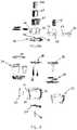
- FIG. 1is an exploded view of a food processor according to an embodiment of the present invention.
- FIG. 2is an exploded parts view of a food processor according to an embodiment of the present invention.
- FIG. 3is a perspective view of a processing bowl and modular lid therefor, utilized with a flat cover, according to an embodiment of the present invention.
- FIG. 4is an exploded, perspective view of the food processing bowl, modular lid and flat cover of FIG. 3 .
- FIG. 5is a perspective view of a processing bowl and modular lid therefor, utilized with a large feed tube, according to an embodiment of the present invention.
- FIG. 6is an exploded, perspective view of the food processing bowl, modular lid and large feed tube of FIG. 5 .
- FIG. 7is a perspective view of a processing bowl and modular lid therefor, utilized with a spiral feed tube, according to an embodiment of the present invention.
- FIG. 8is an exploded, perspective view of the food processing bowl, modular lid and spiral feed tube of FIG. 7 .
- the food processor 10includes base housing 12 having a motor (not shown) disposed within.
- the motoris preferably a conventional electric motor that is reversible and has a variable speed between approximately 500-3,500 RPM.
- the motoris operatively engaged with a drive shaft 16 to cause the drive shaft 16 to rotate.
- the motoris oriented such that the drive shaft 16 extends upwardly from the motor, extending outwardly and/or protruding from a top surface of the base housing 12 .
- the base housing 12may include a user interface electrically connected to the motor to enable a user to control the speed of the motor.
- the user interfacemay include one or more knobs, dials, buttons, toggle switches or the like.
- a terminal end of the drive shaft 16extends outwardly from the base housing and has a plastic adapter shaft 18 engageable and rotatable therewith.
- a distal end of the adapter shaft 18includes a blade coupling configured to engage a cutting blade or other attachment, as discussed hereinafter.
- the food processor 10also includes a bowl 20 removably securable on the base housing 12 .
- the bowl 20has a plurality of protrusions that slidingly engage within corresponding slots in the base housing to retain the bowl 20 on the base housing 12 .
- the bowl 20may be retained on the base 12 via a bayonet style coupling, as is known in the art, that resists forces in both the clockwise and counterclockwise directions.
- Extending upwardly from the center of the bottom wall of the bowl 20is a generally cylindrical central tube sized to accommodate the drive shaft 16 therethrough when the bowl 20 is secured to the base housing 12 in an assembled position.
- a handle 22is integrally molded to the sidewall of the bowl and extends outwardly therefrom, to provide the user with a gripping surface with which to pick up, carry, and otherwise handle the bowl 20 .
- the bowl 20may also be provided with a slicing disc adjustment mechanism 24 configured to mate with the lower end of the adapter shaft 18 and operable from outside the bowl 20 by a user to vary the slice thickness of food items.
- the bowl 20may be provided with a wiper element 26 having a plurality of scraper blades that contact the inner sidewall of the bowl 20 . The wiper element 26 is selectively rotatable by a user about the inner periphery of the bowl 20 , via rotation of a knob 29 accessible above the bowl 20 , to scrape the sides of the bowl 20 during processing of food items.
- a smaller capacity bowl 27may be mounted to the base 12 in lieu of the larger capacity bowl 20 , such as when a smaller volume of food is to be processed.
- the bowl 20has a 16-cup capacity and the smaller bowl 27 has a 4-8 cup capacity.
- the bowl 20may also include an optical channel 31 on the periphery thereof.
- the optical channel 31is configured to receive an optical signal generated by the control unit within the base 12 to ensure the bowl 20 is properly seated on the base 12 , and a lid is properly seated on the bowl 20 .
- an optical signal sent from the baseis reflected and received back at the base by an optical sensor, this indicates that the base, bowl and lid are in proper position for food processing.
- This “optical interlock”ensures that the motor will not operate, and the processing tool will not rotate, unless the bowl and lid are in proper position.
- the base housing 12is shown as being generally square-shaped, it is within the spirit and scope of the present invention that the base housing 12 be of a different shape as long as the base housing 12 can still perform its intended functions, as described herein. Additionally, although the bowl 20 is shown as being removably retained at the top of the base housing 12 , it is within the spirit and scope of the present invention that the base housing 12 be generally L-shaped when viewed from the side, such that the motor is disposed within the vertically-oriented portion and the bowl 20 is disposed on top of the horizontally-oriented portion.
- a cutting tool 28is rotatably securable to the drive shaft 16 .
- the cutting tool 28is rotatably fixed to the adapter shaft 18 proximate the terminal end of the drive shaft 16 and is positioned within the bowl 20 above the top edge of the central tube, when in the assembled position.
- the cutting tool 28is a generally circular metallic disk having at least one slicing blade 30 formed therein as is well understood by those of ordinary skill in the art.
- a dicing mechanismincluding a dicing blade 32 and a dicing plate 34 may be utilized in place of the cutting tool 28 in order to dice food items.
- a plurality of indexing storage containers 36may be inserted into the bowl 20 in nested position with the wiper element 26 , below the dicing plate 34 .
- the wiper element 26may be selectively rotated by a user to index the storage containers 36 to a desired position beneath the dicing plate 34 to collect diced food items therein.
- a spiral cutting blade assembly 38may be utilized in place of the cutting tool 28 in order to cut food items into spiral shapes.
- the food processor 10further includes a lid 40 that is removably securable to a top of the bowl 20 .
- the lid 40defines a substantially circular body sized and dimensioned to cover the bowl 20 , and has an opening 42 formed therein configured to receive one of a flat cover 44 , a large feed tube 46 or a spiral feed tube 48 , as best shown in FIGS. 3-8 .
- the opening 42 in the lidmay be generally oval or kidney shaped, although other shapes and dimensions are envisioned. As illustrated in FIGS.
- the flat cover 44 , large feed tube 46 and spiral feed tube 48each include a lower portion sized and shaped to be received in the opening 42 , and a peripheral flange limiting the insertion depth of the respective flat cover 44 , large feed tube 46 or spiral feed tube 48 into the opening 42 and preventing such components from falling into the bowl 20 .
- the modular lid 40is shown in use with the flat cover 44 .
- the flat cover 44has a lower portion 50 sized and shaped to be received in the opening 42 , and a peripheral flange 52 that contacts the top surface of the lid 40 to prevent the flat cover 44 from falling into the bowl 20 .
- the flat cover 44also includes an optical channel 54 that is configured to align with the optical channel 31 on the periphery of the bowl 20 when the flat cover is in place on the lid 40 and the lid 40 is in place atop the bowl 20 .
- alignment between the optical channel 54 , optical channel 31 and the base 12creates an “optical interlock,” ensuring that the cover 44 , lid 40 and bowl 20 are all in proper position for safe operation.
- the modular lid 40is shown in use with the large feed tube 46 .
- the large feed tube 46has a lower portion 56 sized and shaped to be received in the opening 42 , and a peripheral flange 58 that contacts the top surface of the lid 40 to prevent the large feed tube 46 from falling into the bowl 20 .
- a generally oval shaped openingextends through the feed tube 46 to allow for the insertion of food items to be processed.
- the large feed tube 46similarly includes an optical channel 60 that is configured to align with the optical channel 31 on the periphery of the bowl 20 to establish the “optical interlock” in the manner discussed above.
- the large feed tube 46includes a pusher assembly having a first pusher 62 , a second pusher 64 , and a third pusher 66 .
- the first pusher 62is sized and shaped so as to be slidably received by the feed tube 56 and may be utilized to push large food items through the feed tube 46 and into the cutting tool 28 or other processing implement within the bowl 20 .
- the second pusher 64is sized and shaped so as to be slidably received by an aperture in the first pusher 62 that defines a smaller feed tube opening. The second pusher 64 may be utilized when somewhat smaller food items are to be processed.
- the first pusher 62may be inserted into the feed tube 46 . In this position, the smaller aperture through the first pusher 62 defines the passageway into the bowl 20 .
- the second pusher 64may then be utilized to push the smaller food items through the aperture in the first pusher 62 and into the cutting tool 28 or other processing implement within the bowl 20 .
- the third pusher 66is sized and shaped so as to be slidably received by an aperture in the second pusher 64 that defines an even smaller feed tube opening.
- the third pusher 66may be utilized when even smaller food items are to be processed. For example, when processing very small food items, the first pusher 62 may be inserted into the feed tube 46 and the second pusher 64 may then be inserted into the aperture in the first pusher 62 . In this position, the small aperture through the second pusher 64 defines the passageway into the bowl 20 . The third pusher 66 may then be utilized to push the small food items through the aperture in the second pusher 64 and into the cutting tool 28 or other processing implement within the bowl 20 .
- a usermay configure the feed tube 46 and pusher assembly to provide a feed tube opening that best matches the size of the food items to be processed.
- a large feed tube opening(having a cross sectional area much greater than that of the food items) is not ideal and can adversely impact processing performance.
- a usercan easily vary the area of the feed tube opening to better match the thickness of the food items to be processed. More specifically, matching the feed tube opening area to the thickness of food items to be processed results in greater stability as the food items are pushed into the cutting tool. As a result, improved processing performance may be realized.
- each of the first, second and third pushershave a flange at the top thereof that prevents the pushers from falling through one another and into the bowl when in the nested configuration.
- the bottom of each pusheris generally coplanar.
- the opening in the feed tube 46 , first pusher 62 and second pusher 64are generally the same shape but have decreasing cross-sectional areas. In the preferred embodiment, the openings are generally oval in shape.
- the modular lid 40is shown in use with the spiral feed tube 48 .
- the spiral feed tube 48has a lower portion 68 sized and shaped to be received in the opening 42 in the lid 40 , and a peripheral flange 70 that contacts the top surface of the lid 40 to prevent the spiral feed tube 48 from falling into the bowl 20 .
- a generally cylindrical openingextends through the spiral feed tube 48 to allow for the insertion of food items to be processed.
- the spiral feed tube 48similarly includes an optical channel 72 that is configured to align with the optical channel 31 on the periphery of the bowl 20 to establish the “optical interlock” in the manner discussed above.
- the optical sensor that receives the optical signal indicating that the components are all in locked and proper positionmay be positioned either in the base (in which case the optical signal is reflected by the lid attachment/cover/feed tube), or in the lid attachment/cover/feed tube itself.
- the spiral feed tube 48includes a pusher 74 that is sized and shaped so as to be slidably received by the cylindrical opening in the feed tube 48 and may be utilized to push food items through the feed tube 48 and into the spiral cutter 38 within the bowl 20 .
- pusher 74has a flange at the top thereof that prevents the pusher from falling through the opening in the spiral feed tube 48 and into the bowl 20 .
- the lid 40may include a pushbutton release that may be activated by a user to release the flat cover 44 , large feed tube 46 or spiral feed tube 48 from engagement with the lid 40 .
- the modular lid 40 of the present inventiontherefore allows a user to configure the lid 40 in dependence upon the particular processing operation to be carried out as well as the size of the food items to be processed.
- the lid 40may be fully closed off by utilizing the flat cover 44 .
- the spiral feed tube 48may be utilized.
- the large feed tube 46may be attached to the lid 40 .
- the feed tube openingmay be selectively varied by a user by using one or more of the nestable pushers, in order to more closely match the size of food items to be processed. The ability to tailor the size of the feed tube opening to the size of food items to be processed improves processing performance, as a whole.
Landscapes
- Engineering & Computer Science (AREA)
- Mechanical Engineering (AREA)
- Food Science & Technology (AREA)
- Food-Manufacturing Devices (AREA)
Abstract
Description
Claims (13)
Priority Applications (2)
| Application Number | Priority Date | Filing Date | Title |
|---|---|---|---|
| US15/014,429US10827880B2 (en) | 2016-02-03 | 2016-02-03 | Food processor and modular lid assembly therefor |
| US16/995,320US12256865B2 (en) | 2016-02-03 | 2020-08-17 | Food processor and modular lid assembly therefor |
Applications Claiming Priority (1)
| Application Number | Priority Date | Filing Date | Title |
|---|---|---|---|
| US15/014,429US10827880B2 (en) | 2016-02-03 | 2016-02-03 | Food processor and modular lid assembly therefor |
Related Child Applications (1)
| Application Number | Title | Priority Date | Filing Date |
|---|---|---|---|
| US16/995,320ContinuationUS12256865B2 (en) | 2016-02-03 | 2020-08-17 | Food processor and modular lid assembly therefor |
Publications (2)
| Publication Number | Publication Date |
|---|---|
| US20170215646A1 US20170215646A1 (en) | 2017-08-03 |
| US10827880B2true US10827880B2 (en) | 2020-11-10 |
Family
ID=59385225
Family Applications (2)
| Application Number | Title | Priority Date | Filing Date |
|---|---|---|---|
| US15/014,429Active2038-07-09US10827880B2 (en) | 2016-02-03 | 2016-02-03 | Food processor and modular lid assembly therefor |
| US16/995,320Active2039-05-28US12256865B2 (en) | 2016-02-03 | 2020-08-17 | Food processor and modular lid assembly therefor |
Family Applications After (1)
| Application Number | Title | Priority Date | Filing Date |
|---|---|---|---|
| US16/995,320Active2039-05-28US12256865B2 (en) | 2016-02-03 | 2020-08-17 | Food processor and modular lid assembly therefor |
Country Status (1)
| Country | Link |
|---|---|
| US (2) | US10827880B2 (en) |
Cited By (2)
| Publication number | Priority date | Publication date | Assignee | Title |
|---|---|---|---|---|
| US11452406B2 (en)* | 2017-04-21 | 2022-09-27 | Shuangma Plastic Manufacturing Inc. | Multifunctional food processor |
| USD1035373S1 (en) | 2022-03-07 | 2024-07-16 | Sharkninja Operating Llc | Container and lid of a food processor |
Families Citing this family (8)
| Publication number | Priority date | Publication date | Assignee | Title |
|---|---|---|---|---|
| US10694895B2 (en)* | 2016-02-03 | 2020-06-30 | Conair Corporation | Food processor having indexing storage containers |
| US10638884B2 (en)* | 2016-02-04 | 2020-05-05 | Conair Corporation | Food processor and sidewall cleaning mechanism therefor |
| US11013371B2 (en)* | 2017-03-10 | 2021-05-25 | Vita-Mix Management Corporation | Wireless food processor discs |
| CN207253280U (en)* | 2017-03-24 | 2018-04-20 | 漳州灿坤实业有限公司 | Handle assembly and cooking appliance |
| CN110250948A (en)* | 2018-04-19 | 2019-09-20 | 九阳股份有限公司 | A kind of simple vacuum food processing machine of structure |
| CN110250950A (en)* | 2018-04-19 | 2019-09-20 | 九阳股份有限公司 | A kind of vacuum food processing machine easy to clean |
| CN111407166A (en)* | 2020-03-29 | 2020-07-14 | 梅国强 | Up-down moving clear wall type minced meat and minced steak structure and method based on lower opening |
| CN114903355A (en)* | 2021-02-06 | 2022-08-16 | 杭州九阳小家电有限公司 | Shredding machine |
Citations (15)
| Publication number | Priority date | Publication date | Assignee | Title |
|---|---|---|---|---|
| US4226374A (en) | 1979-04-27 | 1980-10-07 | Cuisinarts, Inc. | Two level feed tube for food processor |
| US4542857A (en) | 1982-03-08 | 1985-09-24 | Chosei Akasaka | Food processor |
| US4614306A (en)* | 1984-10-10 | 1986-09-30 | Kitchenaid, Inc. | Pivoting protector for food processor feed tube |
| US4819882A (en) | 1988-01-07 | 1989-04-11 | Whirlpool Corporation | Food processor food pusher positioning apparatus |
| US20070095959A1 (en)* | 2005-10-28 | 2007-05-03 | Izumi Products Company | Electric grating food processor and grater plate |
| US7252252B2 (en) | 2004-02-18 | 2007-08-07 | Hamilton Beach/Proctor-Silex, Inc. | Food processor lid |
| US7681817B2 (en) | 2006-12-19 | 2010-03-23 | Conair Corporation | Food processor |
| US7708215B2 (en)* | 2006-11-14 | 2010-05-04 | Wang Dong-Lei | Food processor cover |
| US20100206701A1 (en)* | 2005-06-03 | 2010-08-19 | Kenwood Limited | Interlock system |
| US20130233952A1 (en)* | 2012-03-08 | 2013-09-12 | Hamilton Beach Brands, Inc. | Kitchen Appliance for Processing Foodstuff and Method of Operating Same |
| US20140299693A1 (en)* | 2013-04-08 | 2014-10-09 | Conair Corporation | Food processor having removable feed tube |
| US20140299692A1 (en) | 2013-04-08 | 2014-10-09 | Conair Corporation | Food processor having removable feed tube |
| US20140299698A1 (en)* | 2013-04-08 | 2014-10-09 | Conair Corporation | Food processor feed tube assembly |
| US20150037480A1 (en)* | 2013-08-02 | 2015-02-05 | Hamilton Beach Brands, Inc. | Food Processor with Locking Bail Handle |
| US9167938B2 (en)* | 2013-03-15 | 2015-10-27 | Whirlpool Corporation | Food processor mixer attachment |
Family Cites Families (7)
| Publication number | Priority date | Publication date | Assignee | Title |
|---|---|---|---|---|
| US7047872B2 (en)* | 2003-09-17 | 2006-05-23 | Conair Corporation | Optical interlock for appliance |
| US7587974B2 (en)* | 2004-10-26 | 2009-09-15 | Aac Trade Ltd. | Food processor appliances |
| RU2584849C2 (en)* | 2010-12-07 | 2016-05-20 | Бревилл Пти Лимитед | Improved kitchen processor |
| EP2634193B1 (en) | 2012-02-29 | 2015-01-14 | Enzypep B.V. | Side-chain protected oligopeptide fragment condensation using subtilisins in organic solvents |
| US9033269B2 (en)* | 2013-03-01 | 2015-05-19 | Whirlpool Corporation | Linear path food processor |
| US10154759B2 (en)* | 2013-04-08 | 2018-12-18 | Conair Corporation | Lid securing mechanism for food processor |
| US9326640B2 (en)* | 2013-08-07 | 2016-05-03 | Conair Corporation | Food processor feed tube assembly |
- 2016
- 2016-02-03USUS15/014,429patent/US10827880B2/enactiveActive
- 2020
- 2020-08-17USUS16/995,320patent/US12256865B2/enactiveActive
Patent Citations (17)
| Publication number | Priority date | Publication date | Assignee | Title |
|---|---|---|---|---|
| US4226374A (en) | 1979-04-27 | 1980-10-07 | Cuisinarts, Inc. | Two level feed tube for food processor |
| US4542857A (en) | 1982-03-08 | 1985-09-24 | Chosei Akasaka | Food processor |
| US4614306A (en)* | 1984-10-10 | 1986-09-30 | Kitchenaid, Inc. | Pivoting protector for food processor feed tube |
| US4819882A (en) | 1988-01-07 | 1989-04-11 | Whirlpool Corporation | Food processor food pusher positioning apparatus |
| US7252252B2 (en) | 2004-02-18 | 2007-08-07 | Hamilton Beach/Proctor-Silex, Inc. | Food processor lid |
| US7644883B2 (en) | 2004-02-18 | 2010-01-12 | Hamilton Beach Brands, Inc. | Food processor lid |
| US7673823B2 (en) | 2004-02-18 | 2010-03-09 | Hamilton Beach Brands, Inc. | Food processor lid |
| US20100206701A1 (en)* | 2005-06-03 | 2010-08-19 | Kenwood Limited | Interlock system |
| US20070095959A1 (en)* | 2005-10-28 | 2007-05-03 | Izumi Products Company | Electric grating food processor and grater plate |
| US7708215B2 (en)* | 2006-11-14 | 2010-05-04 | Wang Dong-Lei | Food processor cover |
| US7681817B2 (en) | 2006-12-19 | 2010-03-23 | Conair Corporation | Food processor |
| US20130233952A1 (en)* | 2012-03-08 | 2013-09-12 | Hamilton Beach Brands, Inc. | Kitchen Appliance for Processing Foodstuff and Method of Operating Same |
| US9167938B2 (en)* | 2013-03-15 | 2015-10-27 | Whirlpool Corporation | Food processor mixer attachment |
| US20140299693A1 (en)* | 2013-04-08 | 2014-10-09 | Conair Corporation | Food processor having removable feed tube |
| US20140299692A1 (en) | 2013-04-08 | 2014-10-09 | Conair Corporation | Food processor having removable feed tube |
| US20140299698A1 (en)* | 2013-04-08 | 2014-10-09 | Conair Corporation | Food processor feed tube assembly |
| US20150037480A1 (en)* | 2013-08-02 | 2015-02-05 | Hamilton Beach Brands, Inc. | Food Processor with Locking Bail Handle |
Cited By (2)
| Publication number | Priority date | Publication date | Assignee | Title |
|---|---|---|---|---|
| US11452406B2 (en)* | 2017-04-21 | 2022-09-27 | Shuangma Plastic Manufacturing Inc. | Multifunctional food processor |
| USD1035373S1 (en) | 2022-03-07 | 2024-07-16 | Sharkninja Operating Llc | Container and lid of a food processor |
Also Published As
| Publication number | Publication date |
|---|---|
| US12256865B2 (en) | 2025-03-25 |
| US20170215646A1 (en) | 2017-08-03 |
| US20210030208A1 (en) | 2021-02-04 |
Similar Documents
| Publication | Publication Date | Title |
|---|---|---|
| US12256865B2 (en) | Food processor and modular lid assembly therefor | |
| US10694895B2 (en) | Food processor having indexing storage containers | |
| US10638884B2 (en) | Food processor and sidewall cleaning mechanism therefor | |
| US10433675B2 (en) | Adjustable slicing mechanism for a food processor | |
| US6814323B2 (en) | Food processor | |
| US4190208A (en) | Processor and cutter disc | |
| US7520453B2 (en) | Safety actuator for a food processor having a visual indication | |
| US7159808B2 (en) | Combination bowl and internal rotatable tray for a food processor | |
| US8584979B2 (en) | Food processor with multiple processing containers | |
| US12127714B2 (en) | Food processing device | |
| US9615695B2 (en) | Food processor having removable feed tube | |
| US11344157B2 (en) | Blender and food processor combination with safety features | |
| US20220095842A1 (en) | Food processor having external slicing disc adjustment | |
| AU2013200848A1 (en) | Food processor with external control for operating an adjustable cutting tool | |
| WO2017205469A1 (en) | Multi-position food processor system | |
| CN116725401A (en) | Adjustable blade assembly for food processor | |
| US12262850B2 (en) | Food processor having detachable spring-loaded lid | |
| US9635982B2 (en) | Food processor having removable feed tube | |
| US9398831B2 (en) | Food pusher for food processor | |
| US9320391B2 (en) | Food processor blade assembly | |
| US9326640B2 (en) | Food processor feed tube assembly | |
| US9386883B2 (en) | Food processor feed tube assembly | |
| KR20190041171A (en) | A garlic cutting machine |
Legal Events
| Date | Code | Title | Description |
|---|---|---|---|
| AS | Assignment | Owner name:CONAIR CORPORATION, CONNECTICUT Free format text:ASSIGNMENT OF ASSIGNORS INTEREST;ASSIGNORS:ZAKOWSKI, JOSEPH W.;HOTALING, BRYAN;NAPLES, MATTHEW;AND OTHERS;SIGNING DATES FROM 20160112 TO 20160114;REEL/FRAME:037655/0829 | |
| STPP | Information on status: patent application and granting procedure in general | Free format text:RESPONSE TO NON-FINAL OFFICE ACTION ENTERED AND FORWARDED TO EXAMINER | |
| STPP | Information on status: patent application and granting procedure in general | Free format text:FINAL REJECTION MAILED | |
| STPP | Information on status: patent application and granting procedure in general | Free format text:NON FINAL ACTION MAILED | |
| STPP | Information on status: patent application and granting procedure in general | Free format text:RESPONSE TO NON-FINAL OFFICE ACTION ENTERED AND FORWARDED TO EXAMINER | |
| STPP | Information on status: patent application and granting procedure in general | Free format text:FINAL REJECTION MAILED | |
| STPP | Information on status: patent application and granting procedure in general | Free format text:DOCKETED NEW CASE - READY FOR EXAMINATION | |
| STPP | Information on status: patent application and granting procedure in general | Free format text:NOTICE OF ALLOWANCE MAILED -- APPLICATION RECEIVED IN OFFICE OF PUBLICATIONS | |
| STPP | Information on status: patent application and granting procedure in general | Free format text:PUBLICATIONS -- ISSUE FEE PAYMENT VERIFIED | |
| STCF | Information on status: patent grant | Free format text:PATENTED CASE | |
| AS | Assignment | Owner name:CONAIR LLC, CONNECTICUT Free format text:ASSIGNMENT OF ASSIGNORS INTEREST;ASSIGNOR:CONAIR CORPORATION;REEL/FRAME:057216/0011 Effective date:20210512 | |
| AS | Assignment | Owner name:OWL ROCK CAPITAL CORPORATION, AS ADMINISTRATIVE AGENT, NEW YORK Free format text:SECURITY INTEREST;ASSIGNOR:CONAIR LLC;REEL/FRAME:056336/0098 Effective date:20210517 Owner name:BANK OF AMERICA, N.A., AS ADMINISTRATIVE AGENT, NORTH CAROLINA Free format text:SECURITY INTEREST;ASSIGNOR:CONAIR LLC;REEL/FRAME:056336/0166 Effective date:20210517 Owner name:BANK OF AMERICA, N.A., AS ADMINISTRATIVE AGENT, NORTH CAROLINA Free format text:SECURITY INTEREST;ASSIGNOR:CONAIR LLC;REEL/FRAME:056336/0230 Effective date:20210517 | |
| MAFP | Maintenance fee payment | Free format text:PAYMENT OF MAINTENANCE FEE, 4TH YEAR, LARGE ENTITY (ORIGINAL EVENT CODE: M1551); ENTITY STATUS OF PATENT OWNER: LARGE ENTITY Year of fee payment:4 |