US10825839B2 - Touch display device - Google Patents
Touch display deviceDownload PDFInfo
- Publication number
- US10825839B2 US10825839B2US15/448,592US201715448592AUS10825839B2US 10825839 B2US10825839 B2US 10825839B2US 201715448592 AUS201715448592 AUS 201715448592AUS 10825839 B2US10825839 B2US 10825839B2
- Authority
- US
- United States
- Prior art keywords
- mesh
- light emitting
- disposed
- display device
- touch display
- Prior art date
- Legal status (The legal status is an assumption and is not a legal conclusion. Google has not performed a legal analysis and makes no representation as to the accuracy of the status listed.)
- Active, expires
Links
Images


Classifications
- H01L27/1225—
- H—ELECTRICITY
- H10—SEMICONDUCTOR DEVICES; ELECTRIC SOLID-STATE DEVICES NOT OTHERWISE PROVIDED FOR
- H10D—INORGANIC ELECTRIC SEMICONDUCTOR DEVICES
- H10D86/00—Integrated devices formed in or on insulating or conducting substrates, e.g. formed in silicon-on-insulator [SOI] substrates or on stainless steel or glass substrates
- H10D86/40—Integrated devices formed in or on insulating or conducting substrates, e.g. formed in silicon-on-insulator [SOI] substrates or on stainless steel or glass substrates characterised by multiple TFTs
- H10D86/60—Integrated devices formed in or on insulating or conducting substrates, e.g. formed in silicon-on-insulator [SOI] substrates or on stainless steel or glass substrates characterised by multiple TFTs wherein the TFTs are in active matrices
- G—PHYSICS
- G06—COMPUTING OR CALCULATING; COUNTING
- G06F—ELECTRIC DIGITAL DATA PROCESSING
- G06F3/00—Input arrangements for transferring data to be processed into a form capable of being handled by the computer; Output arrangements for transferring data from processing unit to output unit, e.g. interface arrangements
- G06F3/01—Input arrangements or combined input and output arrangements for interaction between user and computer
- G06F3/03—Arrangements for converting the position or the displacement of a member into a coded form
- G06F3/041—Digitisers, e.g. for touch screens or touch pads, characterised by the transducing means
- G06F3/0416—Control or interface arrangements specially adapted for digitisers
- G06F3/0418—Control or interface arrangements specially adapted for digitisers for error correction or compensation, e.g. based on parallax, calibration or alignment
- G—PHYSICS
- G02—OPTICS
- G02F—OPTICAL DEVICES OR ARRANGEMENTS FOR THE CONTROL OF LIGHT BY MODIFICATION OF THE OPTICAL PROPERTIES OF THE MEDIA OF THE ELEMENTS INVOLVED THEREIN; NON-LINEAR OPTICS; FREQUENCY-CHANGING OF LIGHT; OPTICAL LOGIC ELEMENTS; OPTICAL ANALOGUE/DIGITAL CONVERTERS
- G02F1/00—Devices or arrangements for the control of the intensity, colour, phase, polarisation or direction of light arriving from an independent light source, e.g. switching, gating or modulating; Non-linear optics
- G02F1/01—Devices or arrangements for the control of the intensity, colour, phase, polarisation or direction of light arriving from an independent light source, e.g. switching, gating or modulating; Non-linear optics for the control of the intensity, phase, polarisation or colour
- G02F1/13—Devices or arrangements for the control of the intensity, colour, phase, polarisation or direction of light arriving from an independent light source, e.g. switching, gating or modulating; Non-linear optics for the control of the intensity, phase, polarisation or colour based on liquid crystals, e.g. single liquid crystal display cells
- G02F1/133—Constructional arrangements; Operation of liquid crystal cells; Circuit arrangements
- G02F1/136—Liquid crystal cells structurally associated with a semi-conducting layer or substrate, e.g. cells forming part of an integrated circuit
- G02F1/1362—Active matrix addressed cells
- G02F1/1368—Active matrix addressed cells in which the switching element is a three-electrode device
- G—PHYSICS
- G02—OPTICS
- G02F—OPTICAL DEVICES OR ARRANGEMENTS FOR THE CONTROL OF LIGHT BY MODIFICATION OF THE OPTICAL PROPERTIES OF THE MEDIA OF THE ELEMENTS INVOLVED THEREIN; NON-LINEAR OPTICS; FREQUENCY-CHANGING OF LIGHT; OPTICAL LOGIC ELEMENTS; OPTICAL ANALOGUE/DIGITAL CONVERTERS
- G02F1/00—Devices or arrangements for the control of the intensity, colour, phase, polarisation or direction of light arriving from an independent light source, e.g. switching, gating or modulating; Non-linear optics
- G02F1/01—Devices or arrangements for the control of the intensity, colour, phase, polarisation or direction of light arriving from an independent light source, e.g. switching, gating or modulating; Non-linear optics for the control of the intensity, phase, polarisation or colour
- G02F1/13—Devices or arrangements for the control of the intensity, colour, phase, polarisation or direction of light arriving from an independent light source, e.g. switching, gating or modulating; Non-linear optics for the control of the intensity, phase, polarisation or colour based on liquid crystals, e.g. single liquid crystal display cells
- G02F1/133—Constructional arrangements; Operation of liquid crystal cells; Circuit arrangements
- G02F1/1333—Constructional arrangements; Manufacturing methods
- G02F1/133345—Insulating layers
- G—PHYSICS
- G02—OPTICS
- G02F—OPTICAL DEVICES OR ARRANGEMENTS FOR THE CONTROL OF LIGHT BY MODIFICATION OF THE OPTICAL PROPERTIES OF THE MEDIA OF THE ELEMENTS INVOLVED THEREIN; NON-LINEAR OPTICS; FREQUENCY-CHANGING OF LIGHT; OPTICAL LOGIC ELEMENTS; OPTICAL ANALOGUE/DIGITAL CONVERTERS
- G02F1/00—Devices or arrangements for the control of the intensity, colour, phase, polarisation or direction of light arriving from an independent light source, e.g. switching, gating or modulating; Non-linear optics
- G02F1/01—Devices or arrangements for the control of the intensity, colour, phase, polarisation or direction of light arriving from an independent light source, e.g. switching, gating or modulating; Non-linear optics for the control of the intensity, phase, polarisation or colour
- G02F1/13—Devices or arrangements for the control of the intensity, colour, phase, polarisation or direction of light arriving from an independent light source, e.g. switching, gating or modulating; Non-linear optics for the control of the intensity, phase, polarisation or colour based on liquid crystals, e.g. single liquid crystal display cells
- G02F1/133—Constructional arrangements; Operation of liquid crystal cells; Circuit arrangements
- G02F1/1333—Constructional arrangements; Manufacturing methods
- G02F1/13338—Input devices, e.g. touch panels
- G—PHYSICS
- G02—OPTICS
- G02F—OPTICAL DEVICES OR ARRANGEMENTS FOR THE CONTROL OF LIGHT BY MODIFICATION OF THE OPTICAL PROPERTIES OF THE MEDIA OF THE ELEMENTS INVOLVED THEREIN; NON-LINEAR OPTICS; FREQUENCY-CHANGING OF LIGHT; OPTICAL LOGIC ELEMENTS; OPTICAL ANALOGUE/DIGITAL CONVERTERS
- G02F1/00—Devices or arrangements for the control of the intensity, colour, phase, polarisation or direction of light arriving from an independent light source, e.g. switching, gating or modulating; Non-linear optics
- G02F1/01—Devices or arrangements for the control of the intensity, colour, phase, polarisation or direction of light arriving from an independent light source, e.g. switching, gating or modulating; Non-linear optics for the control of the intensity, phase, polarisation or colour
- G02F1/13—Devices or arrangements for the control of the intensity, colour, phase, polarisation or direction of light arriving from an independent light source, e.g. switching, gating or modulating; Non-linear optics for the control of the intensity, phase, polarisation or colour based on liquid crystals, e.g. single liquid crystal display cells
- G02F1/133—Constructional arrangements; Operation of liquid crystal cells; Circuit arrangements
- G02F1/1333—Constructional arrangements; Manufacturing methods
- G02F1/1343—Electrodes
- G02F1/134309—Electrodes characterised by their geometrical arrangement
- G—PHYSICS
- G06—COMPUTING OR CALCULATING; COUNTING
- G06F—ELECTRIC DIGITAL DATA PROCESSING
- G06F3/00—Input arrangements for transferring data to be processed into a form capable of being handled by the computer; Output arrangements for transferring data from processing unit to output unit, e.g. interface arrangements
- G06F3/01—Input arrangements or combined input and output arrangements for interaction between user and computer
- G06F3/03—Arrangements for converting the position or the displacement of a member into a coded form
- G06F3/041—Digitisers, e.g. for touch screens or touch pads, characterised by the transducing means
- G06F3/0412—Digitisers structurally integrated in a display
- G—PHYSICS
- G06—COMPUTING OR CALCULATING; COUNTING
- G06F—ELECTRIC DIGITAL DATA PROCESSING
- G06F3/00—Input arrangements for transferring data to be processed into a form capable of being handled by the computer; Output arrangements for transferring data from processing unit to output unit, e.g. interface arrangements
- G06F3/01—Input arrangements or combined input and output arrangements for interaction between user and computer
- G06F3/03—Arrangements for converting the position or the displacement of a member into a coded form
- G06F3/041—Digitisers, e.g. for touch screens or touch pads, characterised by the transducing means
- G06F3/047—Digitisers, e.g. for touch screens or touch pads, characterised by the transducing means using sets of wires, e.g. crossed wires
- H01L27/1222—
- H01L27/124—
- H01L27/1248—
- H01L27/1251—
- H01L27/1255—
- H01L27/323—
- H01L27/3276—
- H01L29/24—
- H01L29/42356—
- H01L29/78648—
- H01L29/78675—
- H01L29/7869—
- H01L29/78696—
- H—ELECTRICITY
- H10—SEMICONDUCTOR DEVICES; ELECTRIC SOLID-STATE DEVICES NOT OTHERWISE PROVIDED FOR
- H10D—INORGANIC ELECTRIC SEMICONDUCTOR DEVICES
- H10D30/00—Field-effect transistors [FET]
- H10D30/60—Insulated-gate field-effect transistors [IGFET]
- H10D30/67—Thin-film transistors [TFT]
- H10D30/6729—Thin-film transistors [TFT] characterised by the electrodes
- H10D30/673—Thin-film transistors [TFT] characterised by the electrodes characterised by the shapes, relative sizes or dispositions of the gate electrodes
- H10D30/6731—Top-gate only TFTs
- H—ELECTRICITY
- H10—SEMICONDUCTOR DEVICES; ELECTRIC SOLID-STATE DEVICES NOT OTHERWISE PROVIDED FOR
- H10D—INORGANIC ELECTRIC SEMICONDUCTOR DEVICES
- H10D30/00—Field-effect transistors [FET]
- H10D30/60—Insulated-gate field-effect transistors [IGFET]
- H10D30/67—Thin-film transistors [TFT]
- H10D30/6729—Thin-film transistors [TFT] characterised by the electrodes
- H10D30/673—Thin-film transistors [TFT] characterised by the electrodes characterised by the shapes, relative sizes or dispositions of the gate electrodes
- H10D30/6733—Multi-gate TFTs
- H10D30/6734—Multi-gate TFTs having gate electrodes arranged on both top and bottom sides of the channel, e.g. dual-gate TFTs
- H—ELECTRICITY
- H10—SEMICONDUCTOR DEVICES; ELECTRIC SOLID-STATE DEVICES NOT OTHERWISE PROVIDED FOR
- H10D—INORGANIC ELECTRIC SEMICONDUCTOR DEVICES
- H10D30/00—Field-effect transistors [FET]
- H10D30/60—Insulated-gate field-effect transistors [IGFET]
- H10D30/67—Thin-film transistors [TFT]
- H10D30/674—Thin-film transistors [TFT] characterised by the active materials
- H10D30/6741—Group IV materials, e.g. germanium or silicon carbide
- H10D30/6743—Silicon
- H10D30/6745—Polycrystalline or microcrystalline silicon
- H—ELECTRICITY
- H10—SEMICONDUCTOR DEVICES; ELECTRIC SOLID-STATE DEVICES NOT OTHERWISE PROVIDED FOR
- H10D—INORGANIC ELECTRIC SEMICONDUCTOR DEVICES
- H10D30/00—Field-effect transistors [FET]
- H10D30/60—Insulated-gate field-effect transistors [IGFET]
- H10D30/67—Thin-film transistors [TFT]
- H10D30/674—Thin-film transistors [TFT] characterised by the active materials
- H10D30/6755—Oxide semiconductors, e.g. zinc oxide, copper aluminium oxide or cadmium stannate
- H—ELECTRICITY
- H10—SEMICONDUCTOR DEVICES; ELECTRIC SOLID-STATE DEVICES NOT OTHERWISE PROVIDED FOR
- H10D—INORGANIC ELECTRIC SEMICONDUCTOR DEVICES
- H10D30/00—Field-effect transistors [FET]
- H10D30/60—Insulated-gate field-effect transistors [IGFET]
- H10D30/67—Thin-film transistors [TFT]
- H10D30/6757—Thin-film transistors [TFT] characterised by the structure of the channel, e.g. transverse or longitudinal shape or doping profile
- H—ELECTRICITY
- H10—SEMICONDUCTOR DEVICES; ELECTRIC SOLID-STATE DEVICES NOT OTHERWISE PROVIDED FOR
- H10D—INORGANIC ELECTRIC SEMICONDUCTOR DEVICES
- H10D62/00—Semiconductor bodies, or regions thereof, of devices having potential barriers
- H10D62/80—Semiconductor bodies, or regions thereof, of devices having potential barriers characterised by the materials
- H—ELECTRICITY
- H10—SEMICONDUCTOR DEVICES; ELECTRIC SOLID-STATE DEVICES NOT OTHERWISE PROVIDED FOR
- H10D—INORGANIC ELECTRIC SEMICONDUCTOR DEVICES
- H10D64/00—Electrodes of devices having potential barriers
- H10D64/20—Electrodes characterised by their shapes, relative sizes or dispositions
- H10D64/27—Electrodes not carrying the current to be rectified, amplified, oscillated or switched, e.g. gates
- H10D64/311—Gate electrodes for field-effect devices
- H10D64/411—Gate electrodes for field-effect devices for FETs
- H10D64/511—Gate electrodes for field-effect devices for FETs for IGFETs
- H10D64/512—Disposition of the gate electrodes, e.g. buried gates
- H—ELECTRICITY
- H10—SEMICONDUCTOR DEVICES; ELECTRIC SOLID-STATE DEVICES NOT OTHERWISE PROVIDED FOR
- H10D—INORGANIC ELECTRIC SEMICONDUCTOR DEVICES
- H10D86/00—Integrated devices formed in or on insulating or conducting substrates, e.g. formed in silicon-on-insulator [SOI] substrates or on stainless steel or glass substrates
- H10D86/40—Integrated devices formed in or on insulating or conducting substrates, e.g. formed in silicon-on-insulator [SOI] substrates or on stainless steel or glass substrates characterised by multiple TFTs
- H10D86/421—Integrated devices formed in or on insulating or conducting substrates, e.g. formed in silicon-on-insulator [SOI] substrates or on stainless steel or glass substrates characterised by multiple TFTs having a particular composition, shape or crystalline structure of the active layer
- H10D86/423—Integrated devices formed in or on insulating or conducting substrates, e.g. formed in silicon-on-insulator [SOI] substrates or on stainless steel or glass substrates characterised by multiple TFTs having a particular composition, shape or crystalline structure of the active layer comprising semiconductor materials not belonging to the Group IV, e.g. InGaZnO
- H—ELECTRICITY
- H10—SEMICONDUCTOR DEVICES; ELECTRIC SOLID-STATE DEVICES NOT OTHERWISE PROVIDED FOR
- H10D—INORGANIC ELECTRIC SEMICONDUCTOR DEVICES
- H10D86/00—Integrated devices formed in or on insulating or conducting substrates, e.g. formed in silicon-on-insulator [SOI] substrates or on stainless steel or glass substrates
- H10D86/40—Integrated devices formed in or on insulating or conducting substrates, e.g. formed in silicon-on-insulator [SOI] substrates or on stainless steel or glass substrates characterised by multiple TFTs
- H10D86/441—Interconnections, e.g. scanning lines
- H—ELECTRICITY
- H10—SEMICONDUCTOR DEVICES; ELECTRIC SOLID-STATE DEVICES NOT OTHERWISE PROVIDED FOR
- H10D—INORGANIC ELECTRIC SEMICONDUCTOR DEVICES
- H10D86/00—Integrated devices formed in or on insulating or conducting substrates, e.g. formed in silicon-on-insulator [SOI] substrates or on stainless steel or glass substrates
- H10D86/40—Integrated devices formed in or on insulating or conducting substrates, e.g. formed in silicon-on-insulator [SOI] substrates or on stainless steel or glass substrates characterised by multiple TFTs
- H10D86/451—Integrated devices formed in or on insulating or conducting substrates, e.g. formed in silicon-on-insulator [SOI] substrates or on stainless steel or glass substrates characterised by multiple TFTs characterised by the compositions or shapes of the interlayer dielectrics
- H—ELECTRICITY
- H10—SEMICONDUCTOR DEVICES; ELECTRIC SOLID-STATE DEVICES NOT OTHERWISE PROVIDED FOR
- H10D—INORGANIC ELECTRIC SEMICONDUCTOR DEVICES
- H10D86/00—Integrated devices formed in or on insulating or conducting substrates, e.g. formed in silicon-on-insulator [SOI] substrates or on stainless steel or glass substrates
- H10D86/40—Integrated devices formed in or on insulating or conducting substrates, e.g. formed in silicon-on-insulator [SOI] substrates or on stainless steel or glass substrates characterised by multiple TFTs
- H10D86/471—Integrated devices formed in or on insulating or conducting substrates, e.g. formed in silicon-on-insulator [SOI] substrates or on stainless steel or glass substrates characterised by multiple TFTs having different architectures, e.g. having both top-gate and bottom-gate TFTs
- H—ELECTRICITY
- H10—SEMICONDUCTOR DEVICES; ELECTRIC SOLID-STATE DEVICES NOT OTHERWISE PROVIDED FOR
- H10D—INORGANIC ELECTRIC SEMICONDUCTOR DEVICES
- H10D86/00—Integrated devices formed in or on insulating or conducting substrates, e.g. formed in silicon-on-insulator [SOI] substrates or on stainless steel or glass substrates
- H10D86/40—Integrated devices formed in or on insulating or conducting substrates, e.g. formed in silicon-on-insulator [SOI] substrates or on stainless steel or glass substrates characterised by multiple TFTs
- H10D86/481—Integrated devices formed in or on insulating or conducting substrates, e.g. formed in silicon-on-insulator [SOI] substrates or on stainless steel or glass substrates characterised by multiple TFTs integrated with passive devices, e.g. auxiliary capacitors
- H—ELECTRICITY
- H10—SEMICONDUCTOR DEVICES; ELECTRIC SOLID-STATE DEVICES NOT OTHERWISE PROVIDED FOR
- H10K—ORGANIC ELECTRIC SOLID-STATE DEVICES
- H10K59/00—Integrated devices, or assemblies of multiple devices, comprising at least one organic light-emitting element covered by group H10K50/00
- H10K59/10—OLED displays
- H10K59/12—Active-matrix OLED [AMOLED] displays
- H10K59/131—Interconnections, e.g. wiring lines or terminals
- H—ELECTRICITY
- H10—SEMICONDUCTOR DEVICES; ELECTRIC SOLID-STATE DEVICES NOT OTHERWISE PROVIDED FOR
- H10K—ORGANIC ELECTRIC SOLID-STATE DEVICES
- H10K59/00—Integrated devices, or assemblies of multiple devices, comprising at least one organic light-emitting element covered by group H10K50/00
- H10K59/40—OLEDs integrated with touch screens
- G—PHYSICS
- G02—OPTICS
- G02F—OPTICAL DEVICES OR ARRANGEMENTS FOR THE CONTROL OF LIGHT BY MODIFICATION OF THE OPTICAL PROPERTIES OF THE MEDIA OF THE ELEMENTS INVOLVED THEREIN; NON-LINEAR OPTICS; FREQUENCY-CHANGING OF LIGHT; OPTICAL LOGIC ELEMENTS; OPTICAL ANALOGUE/DIGITAL CONVERTERS
- G02F1/00—Devices or arrangements for the control of the intensity, colour, phase, polarisation or direction of light arriving from an independent light source, e.g. switching, gating or modulating; Non-linear optics
- G02F1/01—Devices or arrangements for the control of the intensity, colour, phase, polarisation or direction of light arriving from an independent light source, e.g. switching, gating or modulating; Non-linear optics for the control of the intensity, phase, polarisation or colour
- G02F1/13—Devices or arrangements for the control of the intensity, colour, phase, polarisation or direction of light arriving from an independent light source, e.g. switching, gating or modulating; Non-linear optics for the control of the intensity, phase, polarisation or colour based on liquid crystals, e.g. single liquid crystal display cells
- G02F1/133—Constructional arrangements; Operation of liquid crystal cells; Circuit arrangements
- G02F1/1333—Constructional arrangements; Manufacturing methods
- G02F1/133388—Constructional arrangements; Manufacturing methods with constructional differences between the display region and the peripheral region
- G—PHYSICS
- G02—OPTICS
- G02F—OPTICAL DEVICES OR ARRANGEMENTS FOR THE CONTROL OF LIGHT BY MODIFICATION OF THE OPTICAL PROPERTIES OF THE MEDIA OF THE ELEMENTS INVOLVED THEREIN; NON-LINEAR OPTICS; FREQUENCY-CHANGING OF LIGHT; OPTICAL LOGIC ELEMENTS; OPTICAL ANALOGUE/DIGITAL CONVERTERS
- G02F1/00—Devices or arrangements for the control of the intensity, colour, phase, polarisation or direction of light arriving from an independent light source, e.g. switching, gating or modulating; Non-linear optics
- G02F1/01—Devices or arrangements for the control of the intensity, colour, phase, polarisation or direction of light arriving from an independent light source, e.g. switching, gating or modulating; Non-linear optics for the control of the intensity, phase, polarisation or colour
- G02F1/13—Devices or arrangements for the control of the intensity, colour, phase, polarisation or direction of light arriving from an independent light source, e.g. switching, gating or modulating; Non-linear optics for the control of the intensity, phase, polarisation or colour based on liquid crystals, e.g. single liquid crystal display cells
- G02F1/133—Constructional arrangements; Operation of liquid crystal cells; Circuit arrangements
- G02F1/136—Liquid crystal cells structurally associated with a semi-conducting layer or substrate, e.g. cells forming part of an integrated circuit
- G02F1/1362—Active matrix addressed cells
- G02F1/1368—Active matrix addressed cells in which the switching element is a three-electrode device
- G02F1/13685—Top gates
- G02F2001/133388—
- G02F2001/13685—
- G—PHYSICS
- G06—COMPUTING OR CALCULATING; COUNTING
- G06F—ELECTRIC DIGITAL DATA PROCESSING
- G06F2203/00—Indexing scheme relating to G06F3/00 - G06F3/048
- G06F2203/041—Indexing scheme relating to G06F3/041 - G06F3/045
- G06F2203/04103—Manufacturing, i.e. details related to manufacturing processes specially suited for touch sensitive devices
- H01L27/3262—
- H01L29/4908—
- H01L29/78672—
- H—ELECTRICITY
- H10—SEMICONDUCTOR DEVICES; ELECTRIC SOLID-STATE DEVICES NOT OTHERWISE PROVIDED FOR
- H10D—INORGANIC ELECTRIC SEMICONDUCTOR DEVICES
- H10D30/00—Field-effect transistors [FET]
- H10D30/60—Insulated-gate field-effect transistors [IGFET]
- H10D30/67—Thin-film transistors [TFT]
- H10D30/6729—Thin-film transistors [TFT] characterised by the electrodes
- H10D30/6737—Thin-film transistors [TFT] characterised by the electrodes characterised by the electrode materials
- H10D30/6739—Conductor-insulator-semiconductor electrodes
- H—ELECTRICITY
- H10—SEMICONDUCTOR DEVICES; ELECTRIC SOLID-STATE DEVICES NOT OTHERWISE PROVIDED FOR
- H10K—ORGANIC ELECTRIC SOLID-STATE DEVICES
- H10K59/00—Integrated devices, or assemblies of multiple devices, comprising at least one organic light-emitting element covered by group H10K50/00
- H10K59/10—OLED displays
- H10K59/12—Active-matrix OLED [AMOLED] displays
- H10K59/121—Active-matrix OLED [AMOLED] displays characterised by the geometry or disposition of pixel elements
- H10K59/1213—Active-matrix OLED [AMOLED] displays characterised by the geometry or disposition of pixel elements the pixel elements being TFTs
Definitions
- the present disclosurerelates to a touch display device, and more particularly, to a touch display device including mesh units.
- touch sensing technologieshave developed rapidly.
- consumer electronicsintegrated with touch sensing functions, such as mobile phones, GPS navigator systems, tablet PCs, and laptop PCs.
- Those consumer electronicsare mainly characterized by integrating original display functions with touch sensing functions, so as to perform as a touching display device.
- the sensing electrode for detecting touching signalsare usually made of indium tin oxide (ITO), in order to avoid the interference to display functions.
- ITOindium tin oxide
- the sensing electrode made of indium tin oxidemay lead to higher integrated resistance and be poor in reaction rate.
- a metal meshconsisted of interweaved metal wires are developed in related arts to replace indium tin oxide for increasing the reaction rate.
- the display lightwill be partially blocked by the metal mesh, and the display effect may be influenced by the metal mesh in the touch display device.
- Light emitting unitsare disposed in mesh openings of mesh units for reducing the influence of the mesh units on the display performance of the light emitting units. At least two of the mesh openings have different areas
- a touch display deviceis provided in an embodiment of the present disclosure.
- the touch display deviceincludes a substrate, a plurality of light emitting units, an insulation layer, and a plurality of mesh units.
- the plurality of light emitting unitsare disposed on the substrate.
- the insulation layeris disposed on the plurality of light emitting units.
- the plurality of mesh unitsare disposed on the insulation layer.
- Each of the mesh unitshas a mesh frame and a mesh opening.
- the plurality of light emitting unitsare disposed in the mesh openings. At least two of the mesh openings have different areas.
- FIG. 1is a schematic drawing illustrating a touch display device according to a first embodiment of the present disclosure.
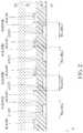
- FIG. 2is a cross-sectional diagram taken along a line A-A′ in FIG. 1 .
- FIG. 3is a schematic drawing illustrating a touch display device according to a second embodiment of the present disclosure.
- FIG. 4is a schematic drawing illustrating a touch display device according to a third embodiment of the present disclosure.
- FIG. 5is a schematic drawing illustrating a touch display device according to a fourth embodiment of the present disclosure.
- FIG. 6is a schematic drawing illustrating a mesh unit according to the fourth embodiment of the present disclosure.
- FIG. 7is a schematic drawing illustrating a touch display device according to a fifth embodiment of the present disclosure.
- FIG. 1is a schematic drawing illustrating a touch display device according to a first embodiment of the present disclosure.
- FIG. 2is a cross-sectional diagram taken along a line A-A′ in FIG. 1 .
- a touch display device 101is provided in this embodiment.
- the touch display device 101includes a substrate 10 , a plurality of light emitting units 20 , an insulation layer 30 , and a plurality of mesh units 40 .
- the plurality of the light emitting units 20are disposed on the substrate 10 .
- the insulation layer 30is disposed on the plurality of the light emitting units 20 .
- the plurality of the mesh units 40are disposed on the insulation layer 30 .
- Each of the mesh units 40has a mesh frame 40 A and a mesh opening 40 B.
- the plurality of the light emitting units 20are disposed in the mesh openings 40 B.
- the substrate 10may include a glass substrate, a plastic substrate, a ceramic substrate, a metal foil, or other suitable rigid or flexible substrates.
- the light emitting units 20may include organic light emitting diode (OLED) units, light emitting diode (LED) units (such as inorganic micro LED, the critical dimension of micro LED is ranged from 0.1 um to 100 um), organic-inorganic mixture light emitting diode units (such as quantum dot LED), or other suitable types of light emitting structures.
- OLEDorganic light emitting diode
- LEDlight emitting diode
- LEDorganic-inorganic mixture light emitting diode units
- quantum dot LEDorganic-inorganic mixture light emitting diode units
- the outline of the light emitting units 20 in FIG. 1is an effective lighting area defined by effective diode structure, and the effective diode structure is the sandwich stacking of cathode-emitting layer-anode.
- the substrate 10may also include a circuit with a plurality of thin film transistors, or other appropriate circuit capable of driving the light emitting units 20 .
- the thin film transistors of the circuit mentioned abovemay include amorphous silicon thin film transistors (a-Si TFTs), poly-silicon thin film transistors (poly-Si TFTs), an oxide semiconductor thin film transistors (such as IGZO TFTs), or other kinds of thin film transistors.
- the insulation layer 30may be an encapsulation layer formed on the substrate 10 and covering the light emitting units 20 , but not limited thereto.
- the insulation layer 30may also include a planarization layer formed between the light emitting units 20 and an encapsulation layer covering the light emitting units 20 .
- the insulation layer 30could be single layer structure or multi-layered structure.
- the material of the insulation layer 30may include silicon oxide, silicon nitride, silicon oxynitride, metal oxide, polymer, resin, or other suitable organic materials and inorganic materials.
- the mesh units 40may include metal mesh units, and the material of the metal mesh units may include aluminum (Al), copper (Cu), molybdenum (Mo), titanium (Ti), silver (Ag), a composition layer of the material mentioned above, or an alloy of the material mentioned above, but not limited thereto.
- the mesh units 40may also be made of other suitable conductive materials, such as oxide conductive materials.
- the mesh frame 40 A of a mesh unit 40may be connected with the mesh frame 40 A of at least one of the adjacent mesh unit 40 to form a mesh shape.
- a touch electrode 40 Xmay be formed by at least one mesh unit 40 .
- the touch display device 101may include at least one touch electrode 40 X formed by at least one mesh unit 40 , but not limited thereto.
- the touch electrode 40 Xmay be used to perform a capacitive touch sensing operation, a resistive touch sensing operation, or other suitable kinds of touch sensing operations.
- the mesh units 40may be used to form a connection part between the touch electrodes, a trace connected with the touch electrode and extending to the peripheral region, or other suitable portions of a touch sensing structure.
- each of the mesh openings 40 Bhas a projection region RG in a direction Z perpendicular to the substrate 10 , and the light emitting units 20 may be disposed within the projection regions RG.
- the mesh units 40do not overlap the light emitting units 20 in the direction Z perpendicular to the substrate 10 for reducing the influence of the mesh units 40 on the display performance of the light emitting units 20 , and the display quality of the touch display device 101 may be enhanced accordingly.
- a distance between each of the light emitting units 20 and the corresponding mesh frame 40 Amay be ranged from 1 um to 10 um in a top view diagram of the touch display device 101 for ensuring that the light emitted from the light emitting units 20 in the direction Z will not be block by the mesh unit 40 .
- each of the light emitting units 20may be disposed within one of the projection regions RG of the mesh openings 40 B respectively.
- each one of the projection regions RGmay be formed corresponding to only one of the light emitting units 20 , but not limited thereto.
- at least one of the projection regions RGmay also be formed corresponding to a plurality of the light emitting units 20 .
- the light emitting units 20may include different light emitting units configured to emit light beams of different colors.
- the light emitting units 20may include a first light emitting unit 21 , a second light emitting unit 22 , and a third light emitting unit 23 configured to emit red light, green light, and blue light respectively, but not limited thereto.
- at least two of the light emitting units 20have different areas, and the areas are defined within the outlines of the light emitting units 20 .
- the area of the third light emitting unit 23may be less than the area of the first light emitting unit 21 and the area of the second light emitting unit 22 for specific color mixing considerations, but not limited thereto.
- the touch electrode 40 Xmay include a plurality of first mesh units 41 and a plurality of second mesh units 42 .
- Each of the first mesh units 41may have a first mesh frame 41 A and a first mesh opening 41 B
- each of the second mesh units 42may have a second mesh frame 42 A and a second mesh opening 42 B.
- the first light emitting unit 21 and the second light emitting units 22may be disposed in the first mesh openings 41 B respectively
- the third light emitting unit 23may be disposed in the second mesh opening 42 B.
- the first light emitting unit 21may be disposed within a first projection region RG 1 of the first mesh opening 41 B
- the second light emitting unit 22may be disposed within the first projection region RG 1 of another first mesh opening 41 B
- the third light emitting unit 23may be disposed within a second projection region RG 2 of the second mesh opening 42 B.
- the second mesh opening 42 Bmay be smaller than the first mesh opening 41 B
- the second projection region RG 2may be smaller than the first projection region RG 1 , but not limited thereto.
- the first light emitting unit 21may be disposed in the first mesh openings 41 B
- the second light emitting unit 21may be disposed in the second mesh openings 42 B
- the third light emitting unit 23may be disposed in a third mesh opening
- the area of the third light emitting unit 23is smaller than the area of the second light emitting unit 21
- the area of the second light emitting unit 23is smaller than the area of the first light emitting unit 21
- the third mesh openingmay be smaller than the second mesh opening 42 B
- the second mesh opening 42 Bmay be smaller than the first mesh opening 41 A.
- the areas of the mesh openings 40 Bmay also be equal to one another for other design considerations.
- the touch display device 101may further include a cover substrate 60 and an adhesive layer 50 .
- the adhesive layer 50may be disposed between the cover substrate 60 and the substrate 10 having the light emitting units 20 and the mesh units 40 disposed thereon for combining the substrate 10 with the cover substrate 60 .
- the mesh units 40are disposed between the cover substrate 60 and the insulation layer 30 .
- the touch display device 101may further include a polarizer and/or a quarter-wave plate (not shown) disposed between the cover substrate 60 and the light emitting units 20 or disposed on the cover substrate 60 for reducing the influence of the ambient light reflected by the touch display device 101 , but not limited thereto.
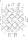
- FIG. 3is a schematic drawing illustrating a touch display device 102 according to a second embodiment of the present disclosure.
- the touch display device 102at least two of the light emitting units 20 are disposed in one of the mesh openings 40 B.
- at least two of the light emitting units 20are disposed within one of the projection regions RG of the mesh openings 40 B.
- each one of the projection regions RGmay be formed corresponding to two of the light emitting units 20 , but not limited thereto. In some embodiments, there may be more than two of the light emitting units 20 disposed in the same mesh opening 40 B.
- the light emitting units 20 disposed within the same projection region RGmay be configured to emit light beams of the same color, but not limited thereto.
- two of the first light emitting units 21may be disposed within the same first projection region RG 1
- two of the second light emitting units 22may be disposed within the same first projection region RG 1
- two of the third light emitting units 23may be disposed within the same second projection region RG 2 .
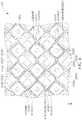
- FIG. 4is a schematic drawing illustrating a touch display device 103 according to a third embodiment of the present disclosure.
- the touch display device 103at least two of the light emitting units 20 are disposed in one of the mesh openings 40 B.
- at least two of the light emitting units 20are disposed within one of the projection regions RG of the mesh openings 40 B.
- the amounts of the light emitting units 20 disposed within at least two of the projection regions RGrespectively may be different from one another.
- the light emitting units 20 disposed within the same projection region RGmay be configured to emit light beams of different colors.
- one of the first light emitting units 21 and one of the third light emitting units 23may be disposed within the same first projection region RG 1
- one of the second light emitting units 22 and one of the third light emitting units 23may be disposed within the same first projection region RG 1 , but not limited thereto.
- FIG. 5is a schematic drawing illustrating a touch display device 104 according to a fourth embodiment of the present disclosure.
- FIG. 6is a schematic drawing illustrating a mesh unit in this embodiment.
- at least one of the mesh frames 40 Aincludes a first end portion E 1 and a second end portion E 2 opposite to the first end portion E 1 , and a gap 40 G is a minimum distance disposed between the first end portion E 1 and the second end portion E 2 .
- the gaps 40 Gmay be used to separate two adjacent touch electrodes 40 X composed of the mesh units 40 , but not limited thereto.
- the first end portion E 1may be electrically isolated from the second end portion E 2 , but not limited thereto. In some embodiments, there may be only one gap 40 G disposed in one of the mesh units 40 , and the first end portion E 1 may be still electrically connected to the second end portion E 2 .
- the mesh frame 40 Amay further include a first mesh corner CR 1 , a second mesh corner CR 2 , a first line portion L 1 and a second line portion L 2 .
- the first line portion L 1is disposed between the first end portion E 1 and the first mesh corner CR 1 .
- the second line portion L 2is disposed between the second end portion E 2 and the second mesh corner CR 2 .
- the shape of the first line portion L 1 and the second line portion L 2is rectangular. At least a portion of the first end portion E 1 , the second end portion E 2 , the first mesh corner CR 1 , and the second mesh corner CR 2 comprise are curved.
- the first mesh corner CR 1is adjacent to the second corner CR 2 , and the gap 40 G is disposed between the first mesh corner CR 1 and the second mesh corner CR 2 .
- the first line portion L 1may have a first width W 1 in a direction perpendicular to the extending direction of the first line portion L 1
- the second line portion L 2may have a second width W 2 in a direction perpendicular to the extending direction of the second line portion L 2 .
- the first width W 1 and the second width W 2may be less than or equal to the width of the gap 40 G, such as a third width W 3 shown in FIG. 6 .
- the width of the gap 40 Gmay be smaller than a distance DS between the first mesh corner CR 1 and the second mesh corner CR 2 for lowering the visual influence of the gap 40 G.
- the distance DSis a minimum distance between the first mesh corner CR 1 and the second mesh corner CR 2 .
- the first end portion E 1may have a first curved edge S 1
- the second end portion E 2may have a second curved edge S 2 , but not limited thereto.
- FIG. 7is a schematic drawing illustrating a touch display device 105 according to a fifth embodiment of the present disclosure.
- the touch display device 105there may be only one gap 40 G disposed in one of the mesh units 40 , and the first end portion E 1 may be still electrically connected to the second end portion E 2 .
- the mesh unit 40 shown in FIG. 7may be a dummy mesh unit in the touch sensing structure, and the gap 40 G may be formed for improving the visual uniformity of the mesh units 40 , but not limited thereto.
- the light emitting unitsare disposed in the mesh openings of the mesh units for preventing the light emitted from the light emitting units from being blocked by the mesh units in the direction perpendicular to the substrate.
- the light emitting strength of the touch display devicemay be enhanced, and the display quality of the touch display device may be improved accordingly.
Landscapes
- Physics & Mathematics (AREA)
- Engineering & Computer Science (AREA)
- Nonlinear Science (AREA)
- General Physics & Mathematics (AREA)
- General Engineering & Computer Science (AREA)
- Theoretical Computer Science (AREA)
- Chemical & Material Sciences (AREA)
- Crystallography & Structural Chemistry (AREA)
- Mathematical Physics (AREA)
- Optics & Photonics (AREA)
- Human Computer Interaction (AREA)
- Microelectronics & Electronic Packaging (AREA)
- Geometry (AREA)
- Devices For Indicating Variable Information By Combining Individual Elements (AREA)
- Thin Film Transistor (AREA)
- Electroluminescent Light Sources (AREA)
- Position Input By Displaying (AREA)
- Liquid Crystal (AREA)
Abstract
Description
Claims (16)
Priority Applications (4)
| Application Number | Priority Date | Filing Date | Title |
|---|---|---|---|
| US15/448,592US10825839B2 (en) | 2016-12-02 | 2017-03-03 | Touch display device |
| CN201711006049.8ACN108153442B (en) | 2016-12-02 | 2017-10-25 | touch display device |
| CN202110536424.XACN113238677B (en) | 2016-12-02 | 2017-10-25 | Touch display device |
| US17/033,666US11444104B2 (en) | 2016-12-02 | 2020-09-25 | Touch display device |
Applications Claiming Priority (2)
| Application Number | Priority Date | Filing Date | Title |
|---|---|---|---|
| US201662429162P | 2016-12-02 | 2016-12-02 | |
| US15/448,592US10825839B2 (en) | 2016-12-02 | 2017-03-03 | Touch display device |
Related Child Applications (1)
| Application Number | Title | Priority Date | Filing Date |
|---|---|---|---|
| US17/033,666ContinuationUS11444104B2 (en) | 2016-12-02 | 2020-09-25 | Touch display device |
Publications (2)
| Publication Number | Publication Date |
|---|---|
| US20180157357A1 US20180157357A1 (en) | 2018-06-07 |
| US10825839B2true US10825839B2 (en) | 2020-11-03 |
Family
ID=62240150
Family Applications (12)
| Application Number | Title | Priority Date | Filing Date |
|---|---|---|---|
| US15/448,592Active2037-11-25US10825839B2 (en) | 2016-12-02 | 2017-03-03 | Touch display device |
| US15/451,416Active2037-10-13US10522566B2 (en) | 2016-12-02 | 2017-03-07 | Touch display device |
| US15/480,423ActiveUS10074669B2 (en) | 2016-12-02 | 2017-04-06 | Display device |
| US15/486,336Active2037-08-20US10325930B2 (en) | 2016-12-02 | 2017-04-13 | Display device |
| US15/489,754ActiveUS10401997B2 (en) | 2016-12-02 | 2017-04-18 | Touch display device with mesh units and anti-static electricity connecting parts |
| US16/402,478ActiveUS10861879B2 (en) | 2016-12-02 | 2019-05-03 | Display device |
| US16/454,065ActiveUS10535681B2 (en) | 2016-12-02 | 2019-06-27 | Touch display device with mesh units and anti-static electricity connecting parts |
| US17/033,666ActiveUS11444104B2 (en) | 2016-12-02 | 2020-09-25 | Touch display device |
| US17/090,223ActiveUS11670640B2 (en) | 2016-12-02 | 2020-11-05 | Display device |
| US18/139,493ActiveUS12040330B2 (en) | 2016-12-02 | 2023-04-26 | Display device |
| US18/739,591PendingUS20240332310A1 (en) | 2016-12-02 | 2024-06-11 | Display device |
| US19/018,018PendingUS20250151407A1 (en) | 2016-12-02 | 2025-01-13 | Display device |
Family Applications After (11)
| Application Number | Title | Priority Date | Filing Date |
|---|---|---|---|
| US15/451,416Active2037-10-13US10522566B2 (en) | 2016-12-02 | 2017-03-07 | Touch display device |
| US15/480,423ActiveUS10074669B2 (en) | 2016-12-02 | 2017-04-06 | Display device |
| US15/486,336Active2037-08-20US10325930B2 (en) | 2016-12-02 | 2017-04-13 | Display device |
| US15/489,754ActiveUS10401997B2 (en) | 2016-12-02 | 2017-04-18 | Touch display device with mesh units and anti-static electricity connecting parts |
| US16/402,478ActiveUS10861879B2 (en) | 2016-12-02 | 2019-05-03 | Display device |
| US16/454,065ActiveUS10535681B2 (en) | 2016-12-02 | 2019-06-27 | Touch display device with mesh units and anti-static electricity connecting parts |
| US17/033,666ActiveUS11444104B2 (en) | 2016-12-02 | 2020-09-25 | Touch display device |
| US17/090,223ActiveUS11670640B2 (en) | 2016-12-02 | 2020-11-05 | Display device |
| US18/139,493ActiveUS12040330B2 (en) | 2016-12-02 | 2023-04-26 | Display device |
| US18/739,591PendingUS20240332310A1 (en) | 2016-12-02 | 2024-06-11 | Display device |
| US19/018,018PendingUS20250151407A1 (en) | 2016-12-02 | 2025-01-13 | Display device |
Country Status (2)
| Country | Link |
|---|---|
| US (12) | US10825839B2 (en) |
| CN (10) | CN112905062B (en) |
Families Citing this family (40)
| Publication number | Priority date | Publication date | Assignee | Title |
|---|---|---|---|---|
| JP2018013567A (en)* | 2016-07-20 | 2018-01-25 | 株式会社ジャパンディスプレイ | Display device |
| US10825839B2 (en) | 2016-12-02 | 2020-11-03 | Innolux Corporation | Touch display device |
| WO2018111247A1 (en) | 2016-12-13 | 2018-06-21 | Intel Corporation | Passivation dielectrics for oxide semiconductor thin film transistors |
| KR102349337B1 (en)* | 2017-07-31 | 2022-01-10 | 삼성디스플레이 주식회사 | Display device |
| JP6959065B2 (en)* | 2017-08-14 | 2021-11-02 | 株式会社ジャパンディスプレイ | Display device |
| KR102494625B1 (en)* | 2017-08-28 | 2023-02-01 | 삼성디스플레이 주식회사 | Display device |
| KR102419557B1 (en)* | 2017-08-28 | 2022-07-08 | 엘지디스플레이 주식회사 | Touch screen panel and display device including the same |
| CN108054286B (en)* | 2017-12-13 | 2020-03-06 | 合肥鑫晟光电科技有限公司 | Electroluminescent device, display device and method of making the same |
| EP3742490B1 (en)* | 2018-01-15 | 2022-06-29 | Lg Chem, Ltd. | Transparent light emitting device display |
| US11257956B2 (en) | 2018-03-30 | 2022-02-22 | Intel Corporation | Thin film transistor with selectively doped oxide thin film |
| US11362215B2 (en) | 2018-03-30 | 2022-06-14 | Intel Corporation | Top-gate doped thin film transistor |
| JP7398860B2 (en)* | 2018-08-08 | 2023-12-15 | 株式会社ジャパンディスプレイ | Manufacturing method of thin film transistor |
| CN208622722U (en)* | 2018-08-30 | 2019-03-19 | 京东方科技集团股份有限公司 | Electrostatic discharge protection circuit and display device |
| KR102650309B1 (en)* | 2018-09-19 | 2024-03-22 | 삼성디스플레이 주식회사 | Touch sensing unit and display device comprising the same |
| KR102713257B1 (en)* | 2018-10-23 | 2024-10-04 | 삼성디스플레이 주식회사 | Display device and manufacturing method thereof |
| CN111221429A (en)* | 2018-11-26 | 2020-06-02 | 南昌欧菲显示科技有限公司 | Touch module, touch screen and preparation method thereof |
| US11061499B2 (en)* | 2018-12-12 | 2021-07-13 | Wuhan China Star Optoelectronics Semiconductor Display Technology Co., Ltd. | Display panel |
| CN109614007B (en)* | 2018-12-12 | 2020-08-11 | 武汉华星光电半导体显示技术有限公司 | Display panel |
| CN109920800A (en)* | 2019-02-28 | 2019-06-21 | 武汉华星光电半导体显示技术有限公司 | A display device and method of making the same |
| CN111725238B (en)* | 2019-03-19 | 2023-08-15 | 群创光电股份有限公司 | Operating module with transistor elements |
| US11616057B2 (en) | 2019-03-27 | 2023-03-28 | Intel Corporation | IC including back-end-of-line (BEOL) transistors with crystalline channel material |
| CN110148592B (en)* | 2019-05-21 | 2020-12-11 | 上海天马有机发光显示技术有限公司 | A display panel and a display device including the same |
| KR102732672B1 (en) | 2019-07-09 | 2024-11-21 | 삼성디스플레이 주식회사 | Touch unit and display device including the same |
| CN112306273A (en)* | 2019-07-26 | 2021-02-02 | 北京小米移动软件有限公司 | Touch display screen and mobile terminal |
| KR102831356B1 (en)* | 2019-10-04 | 2025-07-08 | 삼성디스플레이 주식회사 | Display device |
| KR102726987B1 (en)* | 2019-11-11 | 2024-11-05 | 엘지디스플레이 주식회사 | Liquid crsytal display device |
| KR20210078649A (en) | 2019-12-18 | 2021-06-29 | 삼성디스플레이 주식회사 | Display panel and display device including the same |
| KR20210082316A (en) | 2019-12-24 | 2021-07-05 | 삼성디스플레이 주식회사 | Display panel and display device including the same |
| US11393881B2 (en) | 2020-03-26 | 2022-07-19 | Wuhan China Star Optoelectronics Semiconductor Display Technology Co., Ltd. | Display device and manufacturing method thereof |
| KR20210132497A (en)* | 2020-04-27 | 2021-11-04 | 삼성전자주식회사 | Electronic Device Including A Sensor |
| CN113721780A (en)* | 2020-05-26 | 2021-11-30 | 瀚宇彩晶股份有限公司 | Touch control display panel |
| CN112965305B (en)* | 2020-07-08 | 2023-11-17 | 友达光电股份有限公司 | display panel |
| US20220045061A1 (en)* | 2020-08-06 | 2022-02-10 | Micron Technology, Inc. | Three-node access device for vertical three dimensional (3d) memory |
| CN118466787A (en)* | 2020-08-07 | 2024-08-09 | 京东方科技集团股份有限公司 | Display panel, display device, and method of manufacturing display panel |
| US11709558B2 (en) | 2020-08-07 | 2023-07-25 | Chengdu Boe Optoelectronics Technology Co., Ltd. | Display panel, display apparatus, and method of fabricating display panel |
| KR20220022512A (en) | 2020-08-18 | 2022-02-28 | 삼성디스플레이 주식회사 | Electronic device |
| CN114556274B (en)* | 2020-09-27 | 2024-03-15 | 京东方科技集团股份有限公司 | Touch structure and display device |
| KR102803955B1 (en)* | 2020-11-17 | 2025-05-12 | 삼성디스플레이 주식회사 | Display device |
| CN114967958B (en)* | 2021-02-24 | 2025-06-06 | 京东方科技集团股份有限公司 | Touch panel and manufacturing method thereof, and display touch device |
| US12189909B2 (en)* | 2021-04-16 | 2025-01-07 | Hefei Xinsheng Optoelectronics Technology Co., Ltd. | Touch substrate, manufacturing method thereof and touch device |
Citations (12)
| Publication number | Priority date | Publication date | Assignee | Title |
|---|---|---|---|---|
| US20090201231A1 (en)* | 2008-02-13 | 2009-08-13 | Toshiba Matsushita Display Technology Co., Ltd. | El display device |
| US20150109246A1 (en)* | 2013-10-17 | 2015-04-23 | Lg Innotek Co., Ltd. | Touch window and touch device including the same |
| US20150179713A1 (en)* | 2013-12-24 | 2015-06-25 | Lg Display Co., Ltd. | Organic electroluminescent device and method of fabricating the same |
| US20150179140A1 (en)* | 2006-06-19 | 2015-06-25 | Sharp Kabushiki Kaisha | Display device |
| US20150346866A1 (en)* | 2014-05-30 | 2015-12-03 | Semiconductor Energy Laboratory Co., Ltd. | Touch panel |
| US20160043109A1 (en)* | 2014-08-05 | 2016-02-11 | Lg Display Co., Ltd. | Flexible display devie and method of manufacturing the same |
| US20160103517A1 (en) | 2014-10-10 | 2016-04-14 | Samsung Display Co., Ltd. | Touch sensor and display including the same |
| US20160197610A1 (en) | 2015-01-07 | 2016-07-07 | Samsung Display Co., Ltd. | Touch panel |
| US20160266691A1 (en) | 2015-03-10 | 2016-09-15 | Samsung Display Co., Ltd. | Flexible display device |
| US20160306487A1 (en)* | 2015-04-14 | 2016-10-20 | Samsung Display Co., Ltd. | Touch panel and display device |
| US20170364175A1 (en)* | 2016-06-21 | 2017-12-21 | Samsung Display Co., Ltd. | Touch sensing unit and electronic device having same |
| US20180031880A1 (en)* | 2016-07-29 | 2018-02-01 | Samsung Display Co., Ltd. | Display device |
Family Cites Families (85)
| Publication number | Priority date | Publication date | Assignee | Title |
|---|---|---|---|---|
| US7242398B2 (en)* | 2002-02-18 | 2007-07-10 | Ignis Innovation Inc. | Flexible display device |
| CN1327531C (en)* | 2003-05-19 | 2007-07-18 | 友达光电股份有限公司 | Structure of Low Temperature Polysilicon Thin Film Transistor |
| US7286120B2 (en)* | 2003-11-12 | 2007-10-23 | Hewlett-Packard Development Company, L.P. | Large area display and method of manufacturing same |
| WO2006114747A2 (en)* | 2005-04-28 | 2006-11-02 | Nxp B.V. | Fet device |
| JP2007059128A (en)* | 2005-08-23 | 2007-03-08 | Canon Inc | Organic EL display device and manufacturing method thereof |
| KR101186292B1 (en)* | 2006-01-10 | 2012-09-27 | 삼성전자주식회사 | Transistor and fabrication method thereof and organic light emitting display adopting the transistor |
| US20080001525A1 (en)* | 2006-06-30 | 2008-01-03 | Au Optronics Corporation | Arrangements of color pixels for full color OLED |
| JP4974803B2 (en)* | 2007-08-03 | 2012-07-11 | タツタ電線株式会社 | Shield film for printed wiring board and printed wiring board |
| CN101393924B (en)* | 2007-09-21 | 2015-08-12 | 北京京东方光电科技有限公司 | Electroluminescence display panel |
| CN101414229B (en)* | 2007-10-19 | 2010-09-08 | 集嘉通讯股份有限公司 | Handheld electronic device touch screen execution switching function control method and device thereof |
| TWI360708B (en)* | 2007-12-17 | 2012-03-21 | Au Optronics Corp | Pixel structure, display panel, elecro-optical app |
| US8017045B2 (en)* | 2008-04-16 | 2011-09-13 | Electronics And Telecommunications Research Institute | Composition for oxide semiconductor thin film and field effect transistor using the composition |
| CN101315593B (en)* | 2008-07-18 | 2010-06-16 | 华硕电脑股份有限公司 | Touch control type mobile operation device and touch control method applied to same |
| CN100573261C (en)* | 2008-07-24 | 2009-12-23 | 京东方科技集团股份有限公司 | Color membrane substrates and manufacture method thereof |
| KR101634791B1 (en)* | 2008-11-28 | 2016-06-30 | 삼성디스플레이 주식회사 | Touch sensible organic light emitting diode display |
| KR101100999B1 (en)* | 2009-01-13 | 2011-12-29 | 삼성모바일디스플레이주식회사 | CMOS thin film transistor, manufacturing method thereof and organic light emitting display device having same |
| CN102334091B (en)* | 2009-02-26 | 2016-01-06 | 3M创新有限公司 | Touch panel sensor and there is the patterned substrate of the micro-pattern of covering of low visibility |
| TWI589042B (en)* | 2010-01-20 | 2017-06-21 | 半導體能源研究所股份有限公司 | Light emitting device, flexible light emitting device, electronic device, lighting device, and manufacturing method of light emitting device and flexible light emitting device |
| TWI443829B (en)* | 2010-04-16 | 2014-07-01 | Ind Tech Res Inst | Transistor and manufacturing method thereof |
| JP5638833B2 (en)* | 2010-04-22 | 2014-12-10 | 株式会社ジャパンディスプレイ | Image display device and manufacturing method thereof |
| KR101182231B1 (en)* | 2010-06-04 | 2012-09-12 | 삼성디스플레이 주식회사 | Organic light emitting diode display and method for manufacturing the same |
| JP2012256819A (en)* | 2010-09-08 | 2012-12-27 | Semiconductor Energy Lab Co Ltd | Semiconductor device |
| TW201219944A (en)* | 2010-11-10 | 2012-05-16 | Chunghwa Picture Tubes Ltd | Transistor array substrate |
| US9048142B2 (en)* | 2010-12-28 | 2015-06-02 | Semiconductor Energy Laboratory Co., Ltd. | Semiconductor device |
| CN102655161A (en)* | 2011-05-03 | 2012-09-05 | 京东方科技集团股份有限公司 | Pixel structure, manufacturing method for same, and display device |
| JP6013685B2 (en)* | 2011-07-22 | 2016-10-25 | 株式会社半導体エネルギー研究所 | Semiconductor device |
| CN202217245U (en)* | 2011-08-17 | 2012-05-09 | 宸鸿科技(厦门)有限公司 | Touch control panel |
| JP5855888B2 (en)* | 2011-09-30 | 2016-02-09 | 株式会社ジャパンディスプレイ | Liquid crystal display |
| JP2013125826A (en)* | 2011-12-14 | 2013-06-24 | Renesas Electronics Corp | Semiconductor device and method of manufacturing the same |
| US10002968B2 (en)* | 2011-12-14 | 2018-06-19 | Semiconductor Energy Laboratory Co., Ltd. | Semiconductor device and display device including the same |
| CN102437196B (en)* | 2011-12-15 | 2013-04-03 | 昆山工研院新型平板显示技术中心有限公司 | Low-temperature polycrystalline silicon thin-film transistor and manufacturing method thereof |
| US9048323B2 (en)* | 2012-04-30 | 2015-06-02 | Semiconductor Energy Laboratory Co., Ltd. | Semiconductor device |
| TWI523180B (en)* | 2012-05-07 | 2016-02-21 | 友達光電股份有限公司 | Touch panel, touch display panel and touch display apparatus |
| US8901557B2 (en)* | 2012-06-15 | 2014-12-02 | Semiconductor Energy Laboratory Co., Ltd. | Semiconductor device |
| KR101944503B1 (en)* | 2012-06-21 | 2019-04-18 | 삼성디스플레이 주식회사 | Sensor substrate and sensing display panel having the same |
| CN102751200B (en)* | 2012-06-29 | 2015-06-10 | 京东方科技集团股份有限公司 | Thin film transistor, array substrateand manufacturing method thereof |
| US9329314B2 (en)* | 2012-07-13 | 2016-05-03 | Apple Inc. | Touch screen display with transparent electrical shielding layer |
| CN103729077A (en)* | 2012-10-10 | 2014-04-16 | 东莞万士达液晶显示器有限公司 | Touch display device and touch panel |
| TWI498220B (en)* | 2012-10-31 | 2015-09-01 | Au Optronics Corp | Display panel and method of manufacturing same |
| JP5840598B2 (en)* | 2012-12-17 | 2016-01-06 | 株式会社ジャパンディスプレイ | Display device with touch detection function, electronic device, and manufacturing method of display device with touch detection function |
| KR102109166B1 (en)* | 2013-01-15 | 2020-05-12 | 삼성디스플레이 주식회사 | Thin film transistor and display substrate having the same |
| CN103123927B (en)* | 2013-01-24 | 2015-05-06 | 昆山维信诺显示技术有限公司 | Pixel structure for OLED display screen and metal mask thereof |
| US9052766B2 (en)* | 2013-02-14 | 2015-06-09 | Synaptics Incorporated | Mesh sensor design for reduced visibility in touch screen devices |
| KR101796812B1 (en)* | 2013-02-15 | 2017-11-10 | 엘지디스플레이 주식회사 | Flexible organic light emitting display device and method of manufacturing the same |
| JP2014219986A (en)* | 2013-05-10 | 2014-11-20 | サムソン エレクトロ−メカニックス カンパニーリミテッド. | Touch sensor and electronic device having the same |
| CN103336609B (en)* | 2013-06-17 | 2016-05-18 | 业成光电(深圳)有限公司 | Contact panel and touch control display apparatus |
| CN103336383B (en)* | 2013-07-05 | 2016-08-10 | 南昌欧菲光显示技术有限公司 | Polarisation-filtration module and touch display screen |
| US9818765B2 (en)* | 2013-08-26 | 2017-11-14 | Apple Inc. | Displays with silicon and semiconducting oxide thin-film transistors |
| KR102142855B1 (en)* | 2013-08-29 | 2020-08-31 | 미래나노텍(주) | Wired electrode for touchscreen panel, touchscreen panel using the same and manufacturing method of the same |
| KR20150031917A (en)* | 2013-09-17 | 2015-03-25 | 엘지이노텍 주식회사 | Electrode Plate and Eletrochomic Plate, Electrochomic Mirror and Display Device Using the Same |
| TW201530400A (en)* | 2014-01-22 | 2015-08-01 | Wintek Corp | Touch device |
| US9887253B2 (en)* | 2014-01-27 | 2018-02-06 | Japan Display Inc. | Light emitting element display device |
| KR102313990B1 (en)* | 2014-01-29 | 2021-10-18 | 삼성디스플레이 주식회사 | Flexible display device |
| US10985196B2 (en)* | 2014-02-24 | 2021-04-20 | Lg Display Co., Ltd. | Thin film transistor substrate with intermediate insulating layer and display using the same |
| US20150309600A1 (en)* | 2014-04-23 | 2015-10-29 | Uni-Pixel Displays, Inc. | Method of fabricating a conductive pattern with high optical transmission, low reflectance, and low visibility |
| US9336709B2 (en)* | 2014-04-25 | 2016-05-10 | Apple Inc. | Displays with overlapping light-emitting diodes and gate drivers |
| TW201545028A (en)* | 2014-05-23 | 2015-12-01 | Wintek Corp | Touch panel |
| WO2015194417A1 (en)* | 2014-06-17 | 2015-12-23 | シャープ株式会社 | Semiconductor device |
| CN104123037A (en)* | 2014-07-04 | 2014-10-29 | 业成光电(深圳)有限公司 | Touch panel and manufacturing method thereof |
| TW201602854A (en)* | 2014-07-08 | 2016-01-16 | 勝華科技股份有限公司 | Touch panel |
| KR102202976B1 (en)* | 2014-09-19 | 2021-01-14 | 동우 화인켐 주식회사 | Touch Sensor Panel and Method for Fabricating the same |
| TWI542016B (en)* | 2014-10-03 | 2016-07-11 | 友達光電股份有限公司 | Thin film transistor and display panel |
| KR102221910B1 (en)* | 2014-10-10 | 2021-03-05 | 삼성디스플레이 주식회사 | Display device and method of manufacturing the same |
| CN204065625U (en)* | 2014-10-10 | 2014-12-31 | 京东方科技集团股份有限公司 | A kind of array base palte and liquid crystal indicator |
| KR102250847B1 (en)* | 2014-11-13 | 2021-05-13 | 삼성디스플레이 주식회사 | Display device intergrated touch screen panel |
| US9946426B2 (en)* | 2014-11-25 | 2018-04-17 | Interface Optoelectronics Corporation | Method for forming metal mesh pattern and touch panel |
| CN104375710B (en)* | 2014-12-04 | 2018-01-09 | 合肥鑫晟光电科技有限公司 | A kind of metal grill, touch-screen and display device |
| CN111665669A (en)* | 2015-01-08 | 2020-09-15 | 群创光电股份有限公司 | Display panel |
| KR102288825B1 (en)* | 2015-01-13 | 2021-08-11 | 엘지이노텍 주식회사 | Touch window |
| US10522693B2 (en)* | 2015-01-16 | 2019-12-31 | Semiconductor Energy Laboratory Co., Ltd. | Memory device and electronic device |
| KR102405257B1 (en)* | 2015-01-28 | 2022-06-03 | 삼성디스플레이 주식회사 | Display device |
| KR102264651B1 (en)* | 2015-02-03 | 2021-06-15 | 삼성디스플레이 주식회사 | Display apparatus and method for manufacturing the same |
| US9685469B2 (en)* | 2015-04-03 | 2017-06-20 | Apple Inc. | Display with semiconducting oxide and polysilicon transistors |
| KR102339300B1 (en) | 2015-04-06 | 2021-12-15 | 삼성디스플레이 주식회사 | Flexible touch screen panel and flexible touch screen display device |
| KR102362189B1 (en)* | 2015-04-16 | 2022-02-11 | 삼성디스플레이 주식회사 | Organic light emitting diode display |
| WO2016178498A1 (en)* | 2015-05-04 | 2016-11-10 | Lg Innotek Co., Ltd. | Touch panel |
| US9912897B2 (en)* | 2015-05-11 | 2018-03-06 | Semiconductor Energy Laboratory Co., Ltd. | Imaging device and electronic device |
| JP6562706B2 (en)* | 2015-05-13 | 2019-08-21 | 三菱電機株式会社 | Surface device, touch screen and liquid crystal display device |
| CN105159485B (en)* | 2015-06-18 | 2018-06-05 | 京东方科技集团股份有限公司 | Touch panel and preparation method thereof, display device |
| TWI599834B (en)* | 2015-07-31 | 2017-09-21 | 友達光電股份有限公司 | Pixel structure and its manufacturing method |
| CN105304023A (en)* | 2015-11-18 | 2016-02-03 | 上海大学 | Pixel recession compensation circuit of silicon-based organic light emitting micro-display |
| CN106020581B (en)* | 2016-05-25 | 2018-12-18 | 厦门天马微电子有限公司 | Array substrate and touch-control display panel |
| KR102541552B1 (en)* | 2016-11-30 | 2023-06-07 | 엘지디스플레이 주식회사 | Transistor substrate and organic light emitting display panel and organic light emitting display apparatus using the same |
| US10825839B2 (en) | 2016-12-02 | 2020-11-03 | Innolux Corporation | Touch display device |
| CN107452757B (en)* | 2017-07-31 | 2019-10-22 | 上海天马微电子有限公司 | A display panel, its manufacturing method and display device |
- 2017
- 2017-03-03USUS15/448,592patent/US10825839B2/enactiveActive
- 2017-03-07USUS15/451,416patent/US10522566B2/enactiveActive
- 2017-04-06USUS15/480,423patent/US10074669B2/enactiveActive
- 2017-04-13USUS15/486,336patent/US10325930B2/enactiveActive
- 2017-04-18USUS15/489,754patent/US10401997B2/enactiveActive
- 2017-10-25CNCN202110418521.9Apatent/CN112905062B/enactiveActive
- 2017-10-25CNCN201711006061.9Apatent/CN108153443B/enactiveActive
- 2017-10-25CNCN201711006049.8Apatent/CN108153442B/enactiveActive
- 2017-10-25CNCN202110536424.XApatent/CN113238677B/enactiveActive
- 2017-11-24CNCN201711192163.4Apatent/CN108155194B/enactiveActive
- 2017-11-27CNCN202110533113.8Apatent/CN113257840B/enactiveActive
- 2017-11-27CNCN202110533071.8Apatent/CN113257839B/enactiveActive
- 2017-11-27CNCN201711209703.5Apatent/CN108155195B/enactiveActive
- 2017-11-30CNCN202111109692.XApatent/CN113821122A/enactivePending
- 2017-11-30CNCN201711237517.2Apatent/CN108153444B/enactiveActive
- 2019
- 2019-05-03USUS16/402,478patent/US10861879B2/enactiveActive
- 2019-06-27USUS16/454,065patent/US10535681B2/enactiveActive
- 2020
- 2020-09-25USUS17/033,666patent/US11444104B2/enactiveActive
- 2020-11-05USUS17/090,223patent/US11670640B2/enactiveActive
- 2023
- 2023-04-26USUS18/139,493patent/US12040330B2/enactiveActive
- 2024
- 2024-06-11USUS18/739,591patent/US20240332310A1/enactivePending
- 2025
- 2025-01-13USUS19/018,018patent/US20250151407A1/enactivePending
Patent Citations (14)
| Publication number | Priority date | Publication date | Assignee | Title |
|---|---|---|---|---|
| US20150179140A1 (en)* | 2006-06-19 | 2015-06-25 | Sharp Kabushiki Kaisha | Display device |
| US20090201231A1 (en)* | 2008-02-13 | 2009-08-13 | Toshiba Matsushita Display Technology Co., Ltd. | El display device |
| US20150109246A1 (en)* | 2013-10-17 | 2015-04-23 | Lg Innotek Co., Ltd. | Touch window and touch device including the same |
| CN104571687A (en) | 2013-10-17 | 2015-04-29 | Lg伊诺特有限公司 | Touch window and touch device including the same |
| US20150179713A1 (en)* | 2013-12-24 | 2015-06-25 | Lg Display Co., Ltd. | Organic electroluminescent device and method of fabricating the same |
| CN105138195A (en) | 2014-05-30 | 2015-12-09 | 株式会社半导体能源研究所 | Touch panel |
| US20150346866A1 (en)* | 2014-05-30 | 2015-12-03 | Semiconductor Energy Laboratory Co., Ltd. | Touch panel |
| US20160043109A1 (en)* | 2014-08-05 | 2016-02-11 | Lg Display Co., Ltd. | Flexible display devie and method of manufacturing the same |
| US20160103517A1 (en) | 2014-10-10 | 2016-04-14 | Samsung Display Co., Ltd. | Touch sensor and display including the same |
| US20160197610A1 (en) | 2015-01-07 | 2016-07-07 | Samsung Display Co., Ltd. | Touch panel |
| US20160266691A1 (en) | 2015-03-10 | 2016-09-15 | Samsung Display Co., Ltd. | Flexible display device |
| US20160306487A1 (en)* | 2015-04-14 | 2016-10-20 | Samsung Display Co., Ltd. | Touch panel and display device |
| US20170364175A1 (en)* | 2016-06-21 | 2017-12-21 | Samsung Display Co., Ltd. | Touch sensing unit and electronic device having same |
| US20180031880A1 (en)* | 2016-07-29 | 2018-02-01 | Samsung Display Co., Ltd. | Display device |
Also Published As
Similar Documents
| Publication | Publication Date | Title |
|---|---|---|
| US11444104B2 (en) | Touch display device | |
| US11669213B2 (en) | Semiconductor device | |
| US11387261B2 (en) | Array substrate and display device | |
| US10332952B2 (en) | Display unit, method of manufacturing display unit, and electronic apparatus | |
| US9583550B2 (en) | Display device | |
| US11914811B2 (en) | Display substrate and preparation method therefor, and display device | |
| US10186569B2 (en) | Display device having an auxiliary electrode on the substrate with an end surface contacting an electrode of the organic light emitting element | |
| US11038139B2 (en) | Organic electroluminescent devices, displays and mobile communication devices | |
| US20130075737A1 (en) | Organic Light-Emitting Display Apparatus | |
| US11054955B2 (en) | Display device | |
| US10521039B2 (en) | Method for manufacturing flexible touch display panel | |
| CN113363291A (en) | Display device | |
| JP2021022374A (en) | Display apparatus having touch electrodes | |
| US11211444B2 (en) | Display apparatus | |
| JP2019035835A (en) | Display device | |
| US9419068B2 (en) | Organic EL display device and method of manufacturing organic EL display device | |
| US11340737B2 (en) | Touch structure and method for manufacturing the same, touch substrate, display substrate | |
| KR101636146B1 (en) | Thin film transistor, and method of fabricating the same | |
| KR20210074549A (en) | Organic light emitting display device | |
| US20240276844A1 (en) | Display substrate and display device | |
| KR20140077690A (en) | Display device | |
| CN110224010B (en) | OLED display substrate, display panel and preparation method of OLED display substrate | |
| WO2023097599A1 (en) | Display substrate and electronic device | |
| CN219843922U (en) | display device | |
| WO2020041975A1 (en) | Display panel and display device |
Legal Events
| Date | Code | Title | Description |
|---|---|---|---|
| AS | Assignment | Owner name:INNOLUX CORPORATION, TAIWAN Free format text:ASSIGNMENT OF ASSIGNORS INTEREST;ASSIGNORS:LIN, HSIAO-LANG;YUEH, JUI-JEN;WANG, CHAO-HSIANG;REEL/FRAME:041447/0785 Effective date:20170302 | |
| STPP | Information on status: patent application and granting procedure in general | Free format text:NON FINAL ACTION MAILED | |
| STPP | Information on status: patent application and granting procedure in general | Free format text:RESPONSE TO NON-FINAL OFFICE ACTION ENTERED AND FORWARDED TO EXAMINER | |
| STPP | Information on status: patent application and granting procedure in general | Free format text:FINAL REJECTION MAILED | |
| STPP | Information on status: patent application and granting procedure in general | Free format text:DOCKETED NEW CASE - READY FOR EXAMINATION | |
| STPP | Information on status: patent application and granting procedure in general | Free format text:NON FINAL ACTION MAILED | |
| STPP | Information on status: patent application and granting procedure in general | Free format text:RESPONSE TO NON-FINAL OFFICE ACTION ENTERED AND FORWARDED TO EXAMINER | |
| STPP | Information on status: patent application and granting procedure in general | Free format text:NOTICE OF ALLOWANCE MAILED -- APPLICATION RECEIVED IN OFFICE OF PUBLICATIONS | |
| STPP | Information on status: patent application and granting procedure in general | Free format text:NOTICE OF ALLOWANCE MAILED -- APPLICATION RECEIVED IN OFFICE OF PUBLICATIONS | |
| STPP | Information on status: patent application and granting procedure in general | Free format text:AWAITING TC RESP., ISSUE FEE NOT PAID | |
| STPP | Information on status: patent application and granting procedure in general | Free format text:PUBLICATIONS -- ISSUE FEE PAYMENT VERIFIED | |
| STCF | Information on status: patent grant | Free format text:PATENTED CASE | |
| MAFP | Maintenance fee payment | Free format text:PAYMENT OF MAINTENANCE FEE, 4TH YEAR, LARGE ENTITY (ORIGINAL EVENT CODE: M1551); ENTITY STATUS OF PATENT OWNER: LARGE ENTITY Year of fee payment:4 | |
| AS | Assignment | Owner name:RED OAK INNOVATIONS LIMITED, IRELAND Free format text:ASSIGNMENT OF ASSIGNORS INTEREST;ASSIGNOR:INNOLUX CORPORATION;REEL/FRAME:069206/0903 Effective date:20240925 |