US10825471B2 - Voice energy detection - Google Patents
Voice energy detectionDownload PDFInfo
- Publication number
- US10825471B2 US10825471B2US15/942,693US201815942693AUS10825471B2US 10825471 B2US10825471 B2US 10825471B2US 201815942693 AUS201815942693 AUS 201815942693AUS 10825471 B2US10825471 B2US 10825471B2
- Authority
- US
- United States
- Prior art keywords
- ved
- microphone
- microphones
- energy
- circuit
- Prior art date
- Legal status (The legal status is an assumption and is not a legal conclusion. Google has not performed a legal analysis and makes no representation as to the accuracy of the status listed.)
- Active
Links
- 238000001514detection methodMethods0.000titleclaimsabstractdescription50
- 238000012545processingMethods0.000claimsabstractdescription20
- 230000006870functionEffects0.000claimsdescription21
- 230000008859changeEffects0.000claimsdescription7
- 238000001914filtrationMethods0.000claimsdescription6
- 238000000034methodMethods0.000claimsdescription6
- 238000003058natural language processingMethods0.000claimsdescription6
- 230000004044responseEffects0.000claimsdescription6
- 230000008569processEffects0.000claimsdescription4
- 230000002452interceptive effectEffects0.000claimsdescription3
- 230000007704transitionEffects0.000claims3
- 238000013461designMethods0.000description43
- 230000008901benefitEffects0.000description12
- 230000006872improvementEffects0.000description5
- 238000009825accumulationMethods0.000description4
- 238000010586diagramMethods0.000description4
- 230000009977dual effectEffects0.000description3
- 238000012986modificationMethods0.000description3
- 230000004048modificationEffects0.000description3
- 238000004088simulationMethods0.000description3
- 230000001052transient effectEffects0.000description3
- 241001481833Coryphaena hippurusSpecies0.000description2
- 238000013459approachMethods0.000description2
- 238000012544monitoring processMethods0.000description2
- 229920006395saturated elastomerPolymers0.000description2
- 238000001228spectrumMethods0.000description2
- AOUOVFRSCMDPFA-QSDJMHMYSA-N(2s)-2-[[(2s)-2-[[(2s)-2-[[(2s)-2-amino-3-carboxypropanoyl]amino]-4-carboxybutanoyl]amino]-3-methylbutanoyl]amino]butanedioic acidChemical compoundOC(=O)C[C@@H](C(O)=O)NC(=O)[C@H](C(C)C)NC(=O)[C@H](CCC(O)=O)NC(=O)[C@@H](N)CC(O)=OAOUOVFRSCMDPFA-QSDJMHMYSA-N0.000description1
- 239000003990capacitorSubstances0.000description1
- 230000003247decreasing effectEffects0.000description1
- 230000003111delayed effectEffects0.000description1
- 230000008030eliminationEffects0.000description1
- 238000003379elimination reactionMethods0.000description1
- 238000002955isolationMethods0.000description1
- 230000000737periodic effectEffects0.000description1
- 238000012805post-processingMethods0.000description1
- 238000013139quantizationMethods0.000description1
- 230000008707rearrangementEffects0.000description1
Images


Classifications
- G—PHYSICS
- G10—MUSICAL INSTRUMENTS; ACOUSTICS
- G10L—SPEECH ANALYSIS TECHNIQUES OR SPEECH SYNTHESIS; SPEECH RECOGNITION; SPEECH OR VOICE PROCESSING TECHNIQUES; SPEECH OR AUDIO CODING OR DECODING
- G10L25/00—Speech or voice analysis techniques not restricted to a single one of groups G10L15/00 - G10L21/00
- G10L25/78—Detection of presence or absence of voice signals
- G10L25/84—Detection of presence or absence of voice signals for discriminating voice from noise
- G—PHYSICS
- G10—MUSICAL INSTRUMENTS; ACOUSTICS
- G10L—SPEECH ANALYSIS TECHNIQUES OR SPEECH SYNTHESIS; SPEECH RECOGNITION; SPEECH OR VOICE PROCESSING TECHNIQUES; SPEECH OR AUDIO CODING OR DECODING
- G10L15/00—Speech recognition
- G10L15/08—Speech classification or search
- G10L15/18—Speech classification or search using natural language modelling
- G10L15/1815—Semantic context, e.g. disambiguation of the recognition hypotheses based on word meaning
- G—PHYSICS
- G10—MUSICAL INSTRUMENTS; ACOUSTICS
- G10L—SPEECH ANALYSIS TECHNIQUES OR SPEECH SYNTHESIS; SPEECH RECOGNITION; SPEECH OR VOICE PROCESSING TECHNIQUES; SPEECH OR AUDIO CODING OR DECODING
- G10L15/00—Speech recognition
- G10L15/22—Procedures used during a speech recognition process, e.g. man-machine dialogue
- G—PHYSICS
- G10—MUSICAL INSTRUMENTS; ACOUSTICS
- G10L—SPEECH ANALYSIS TECHNIQUES OR SPEECH SYNTHESIS; SPEECH RECOGNITION; SPEECH OR VOICE PROCESSING TECHNIQUES; SPEECH OR AUDIO CODING OR DECODING
- G10L25/00—Speech or voice analysis techniques not restricted to a single one of groups G10L15/00 - G10L21/00
- G10L25/03—Speech or voice analysis techniques not restricted to a single one of groups G10L15/00 - G10L21/00 characterised by the type of extracted parameters
- G10L25/21—Speech or voice analysis techniques not restricted to a single one of groups G10L15/00 - G10L21/00 characterised by the type of extracted parameters the extracted parameters being power information
- G—PHYSICS
- G10—MUSICAL INSTRUMENTS; ACOUSTICS
- G10L—SPEECH ANALYSIS TECHNIQUES OR SPEECH SYNTHESIS; SPEECH RECOGNITION; SPEECH OR VOICE PROCESSING TECHNIQUES; SPEECH OR AUDIO CODING OR DECODING
- G10L15/00—Speech recognition
- G10L15/08—Speech classification or search
- G10L2015/088—Word spotting
- G—PHYSICS
- G10—MUSICAL INSTRUMENTS; ACOUSTICS
- G10L—SPEECH ANALYSIS TECHNIQUES OR SPEECH SYNTHESIS; SPEECH RECOGNITION; SPEECH OR VOICE PROCESSING TECHNIQUES; SPEECH OR AUDIO CODING OR DECODING
- G10L25/00—Speech or voice analysis techniques not restricted to a single one of groups G10L15/00 - G10L21/00
- G10L25/78—Detection of presence or absence of voice signals
- G10L2025/783—Detection of presence or absence of voice signals based on threshold decision
- G—PHYSICS
- G10—MUSICAL INSTRUMENTS; ACOUSTICS
- G10L—SPEECH ANALYSIS TECHNIQUES OR SPEECH SYNTHESIS; SPEECH RECOGNITION; SPEECH OR VOICE PROCESSING TECHNIQUES; SPEECH OR AUDIO CODING OR DECODING
- G10L25/00—Speech or voice analysis techniques not restricted to a single one of groups G10L15/00 - G10L21/00
- G10L25/03—Speech or voice analysis techniques not restricted to a single one of groups G10L15/00 - G10L21/00 characterised by the type of extracted parameters
- G10L25/18—Speech or voice analysis techniques not restricted to a single one of groups G10L15/00 - G10L21/00 characterised by the type of extracted parameters the extracted parameters being spectral information of each sub-band
Definitions
- VEDVoice energy detection
- VEDcan be used to detect the presence or absence of human speech.
- VEDcan be used to detect speech coding, speech recognition, and the like.
- a systemcan use a voice energy detection (VED) circuit along with a capture buffer for improved performance and lower power dissipation.
- VEDvoice energy detection
- a VED assigned to each microphone in the systemcombing the output of more than one VED to improve the detection probability or reduce the false alarm rate can improve the post detection signal-to-noise ratio.
- One or more VED circuitscan be dynamically selected based on background energy and detection performance.
- a digital VED algorithmcan dynamically change the oversampling ratio (OSR) values and passband bandwidth as a function of the loudness of the background noise and desired signal levels. If the desired signal or noise is strong, then the OSR can be reduced to save power. If desired speech is detected, then the OSR value can increase to get the target SNR for the remaining audio processing needs.
- OSRoversampling ratio
- FIG. 1illustrates an overview of a VED system according to one or more exemplary aspects of the disclosed subject matter
- FIG. 2illustrates an exemplary analog voice energy detection (AVED) architecture according to one or more aspects of the disclosed subject matter
- FIG. 3illustrates an exemplary external AVED microphone input filter according to one or more aspects of the disclosed subject matter
- FIG. 4illustrates an AVED comparator according to one or more exemplary aspects of the disclosed subject matter
- FIG. 5illustrates an exemplary AVED finite state machine (FSM) according to one or more aspects of the disclosed subject matter
- FIG. 6is an exemplary simulation output according to one or more aspects of the disclosed subject matter
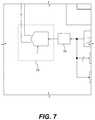
- FIG. 7illustrates an exemplary AVED digital-to-analog convertor (DAC) according to one or more aspects of the disclosed subject matter
- FIG. 8illustrates an exemplary AVED gain and integrator according to one or more aspects of the disclosed subject matter
- FIG. 9illustrates an exemplary AVED post digital filter according to one or more aspects of the disclosed subject matter
- FIG. 10illustrates an exemplary AVED automatic gain control (AGC) support according to one or more aspects of the disclosed subject matter
- FIG. 11illustrates an AVED and digital voice energy detection (DVED) system according to one or more exemplary aspects of the disclosed subject matter
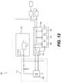
- FIG. 12illustrates an exemplary DVED microphone input according to one or more aspects of the disclosed subject matter
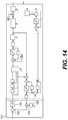
- FIG. 13illustrates an exemplary DVED CIC decimator filter according to one or more aspects of the disclosed subject matter
- FIG. 14illustrates an exemplary DVED front end configured for DVED front end processing according to one or more aspects of the disclosed subject matter
- FIG. 15illustrates exemplary microphone bias architecture according to one or more aspects of the disclosed subject matter
- FIG. 16illustrates an exemplary AVED system according to one or more aspects of the disclosed subject matter
- FIG. 17illustrates an exemplary AVED system according to one or more aspects of the disclosed subject matter
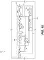
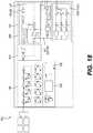
- FIG. 18illustrates an exemplary DVED system according to one or more aspects of the disclosed subject matter
- FIG. 19illustrates an exemplary capture buffer according to one or more aspects of the disclosed subject matter
- FIG. 20Ais an exemplary AVED system according to one or more aspects of the disclosed subject matter
- FIG. 20Bis a microphone input and DAC accumulation output according to one or more exemplary aspects of the disclosed subject matter
- FIG. 21is an exemplary portion of a DVED system according to one or more aspects of the disclosed subject matter.
- FIG. 22illustrates an exemplary capture buffer according to one or more aspects of the disclosed subject matter
- FIG. 23illustrates an exemplary legacy design according to one or more aspects of the disclosed subject matter
- FIG. 24illustrates a first design according to one or more exemplary aspects of the disclosed subject matter
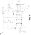
- FIG. 25illustrates a second design according to one or more exemplary aspects of the disclosed subject matter
- FIG. 26illustrates a third design according to one or more exemplary aspects of the disclosed subject matter
- FIG. 27illustrates a fourth design according to one or more exemplary aspects of the disclosed subject matter
- FIG. 28Aillustrates a first multiple microphone bias generator according to one or more aspect of the disclosed subject matter
- FIG. 28Billustrates a second multiple microphone bias generator according to one or more exemplary aspect of the disclosed subject matter
- FIG. 28Cillustrates a third multiple microphone bias generator according to one or more exemplary aspects of the disclosed subject matter.
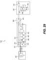
- FIG. 29illustrates a digital VED clocking diagram according to one or more exemplary aspects of the disclosed subject matter.
- a VED systemcan include a VED assigned to each microphone in the system, combining the output of more than one VED to improve the detection probability, reduce the false alarm rate, and/or improve the post detection signal-to-noise ratio (SNR).
- the VED systemcan dynamically select one or more VED circuits based upon background energy and detection performance.
- the VED systemcan include several advantages. For example, as further described herein, the system can use a VED circuit along with a capture buffer for improved performance and lower power dissipation.
- the systemcan adapt an electret condenser microphone (ECM) interface and bias generators to go from VED mode to normal audio capture mode.
- ECMelectret condenser microphone
- the systemcan dynamically change Rbias and Vbias at the same time.
- a VED algorithmcan include slope delta modulation filtering.
- VED algorithmcan use multiple sub bands of different widths, center frequencies, and scale factors where each sub band is compared against another sub band. The differences can then be compared against detection thresholds.
- a VED algorithmcan combine both techniques to improve performance.
- the combination of VED algorithmscan be configured to perform slope delta modulation filtering, compare each sub band in a plurality of sub bands to any other sub band in the plurality of sub bands, the sub bands having different widths, center frequencies, and scale factors, and compare differences from each sub band comparison with a detection threshold, and identify a speech presence when there is a difference in speech energy between the sub bands.
- the VED systemcan also include low power energy monitoring.
- an external CPUcan wake up periodically and adjust the VED thresholds and input levels based on an average energy level.
- the VED systemcan adjust the input level and detection thresholds based upon false alarm rates for the VED function.
- a CPUcan periodically wake up the normal audio paths to monitor noise and signal levels to calibrate the VED thresholds. Further, the CPU can periodically monitor the background noise spectra and or desired talker speech spectra and adjust the VED sub band filters to maximize probability of wake word detection or minimize false alarm rates.
- a wake wordcan trigger functionality (e.g., interactive functionality to play music, use an electronic personal assistant, interact with Internet of Things devices, etc.) of an electronic device.
- a digital VED algorithmcan dynamically change the oversampling ratio (OSR) values and passband bandwidth as a function of the loudness of the background noise and/or desired signal levels. If the desired signal or noise is strong, then the OSR can be reduced to save power. If desired speech is detected, then the OSR value can increase to get the target signal-to-noise ratio (SNR) for the remaining audio processing needs.
- OSRoversampling ratio
- SNRtarget signal-to-noise ratio
- FIG. 1illustrates an overview of the VED system 100 according to one or more exemplary aspects of the disclosed subject matter.
- the VED system 100can include a microphone 105 , a VED 110 , a multiplexer 125 , a keyword detection block 130 , a power manager 135 , and a contextual/NLP block 140 .
- the designcan include low power wake-on-word processing capability.
- the low power wake-on-word processing capabilitycan be done in a 3 step process.
- Step 1(as indicated by S 115 ): Detect voice energy from a microphone 105 via voice energy detection using predetermined hardware (e.g., VED 110 ) in the system.
- Step 2(as indicated by S 120 ): Keyword Detection—Detect a pre-determined wake word (e.g., “Hello,” “Hello, Computer,” etc.) in a Cortex-M0 (CM0) of DSP block (e.g., keyword detection block 130 ) with the normal microphone paths.
- Step 3(as indicated by S 125 ): NLP—Contextual and/or Natural Language processing in a contextual/NLP block 140 . This can extend into provider's cloud processing.
- VEDcan be used for power savings.
- VEDcan wake up the keyword detect circuits when there is enough energy in the selected microphones. This can be for an indoor audio environment with 2 meter target range, for example.
- Advantagescan include low cost, low power, and similar or better performance.
- Table 1includes exemplary operations information.
- FIG. 2illustrates an exemplary analog voice energy detection (AVED) architecture 200 according to one or more aspects of the disclosed subject matter.
- the AVED architecture 200can include an external AVED microphone input filter 205 (which can represent one or more AVED microphone input filters), a comparator 210 , an FSM 215 , an AVED DAC 220 , an AVED gain and integrator 225 , one or more analog MEM and ECMs 245 (which can represent one or more analog MEM and ECMs), a first accumulator 250 positioned between a multiplier 255 and a delay 260 , slope delta modulator architecture, additional register controls for added flexibility, post digital filter 230 , leaky gain integrator, multi VED combiner, threshold detection and automatic gain control (AGC) support circuitry (e.g., see FIG.
- AGCautomatic gain control
- a second accumulator 265positioned between an absolute value function 235 and up counter 240 , a multiplexer 270 positioned between the AVED microphone input filter(s) 205 and a subtractor 275 , and an adder 280 positioned between the post digital filter 230 , a threshold block 285 , and a second multiplexer 290 receiving input from a second VED finite impulse response (FIR) output 295 .
- FIRfinite impulse response
- operation of the AVEDcan include one of three microphone input signals being selected from one of the three microphones 245 . It should be appreciated that changing the multiplexer (mux) can make the output unreliable for 8-32 clocks, for example, until the state machine can settle. Additionally, DC offset may also need to settle.
- the selected microphone signalcan be compared against a digital-to-analog converter (DAC) signal reference (subtraction) from the AVED DAC 220 .
- Comparator outputE ⁇ 1,+1 ⁇is directly fed back into the finite-state machine (FSM) 215 block. FSM counts consecutive number of samples that are the same.
- the last N samplesare the same, increase the gain by a factor of 2 (although it may depend on lookup table (LUT)). If any of the past N samples differ, decrease the gain by a factor of 2 (similarly, may depend on LUT). Gain is saturated at both the low and high end. If the comparator output is a consecutive stream of “+1”s or “ ⁇ 1”s, then the loop is not tracking the input, therefore loop gain should be increased. If the output is toggling between values, then the loop is tracking the input, and the loop gain should be decreased. Or if the output is toggling, then there is possibly a high frequency signal. Output from the comparator 210 is multiplied by the FSM gain and accumulated. Output from the accumulator 250 is input to the DAC. The DAC 220 should act on the input in the next clock cycle for minimum delay.
- LUTlookup table
- FIG. 3illustrates an exemplary external AVED microphone input filter 205 according to one or more exemplary aspects of the disclosed subject matter.
- the AVED microphone input filter 205can be connected to an ECM microphone (e.g., ECM microphone 245 ) externally, as well as being connected to components including a programmable gate array with an analog digital convertor (PGA+ADC) 305 , a VED block 310 , an analog multiplexer 315 , and a low drop out regulator 320 .
- the VED microphone input signalincludes a low pass filter (LPF) and a high pass filter (HPF).
- LPFlow pass filter
- HPFhigh pass filter
- ECMelectric condenser microphone
- MEMsmicroelectromechanical systems
- RCsingle pole resistor-capacitor
- the LPFcan be a 3 dB bandwidth between 8 KHz and 12 KHz
- the HPFcan be 50 Hz.
- the microphone bias supplycan be optimized for lowest power dissipation for the microphone.
- ECM1.8V digital is possible, and external Rbias can be adjusted using the low drop out regulator (LDO) in a low power and/or lower voltage mode.
- LDOlow drop out regulator
- microphone bias noisecan be kept at chip output ⁇ 1-2 mV RMS (i.e., integrated 0.1-32 KHz).
- the 1.8V from digitalcan be used. Additionally, avoiding switching transients on microphone bias can prevent more settling time needed for wake on word processing.
- FIG. 4illustrates an AVED comparator 210 according to one or more exemplary aspects of the disclosed subject matter.
- the AVED comparator 210can be positioned between the subtractor 275 and the FSM 215 .
- the voltage offset and input referred noisecan be kept low.
- the microphone speech input signal amplitudecan be 100 uV RMS so noise should be small in comparison.
- An 8 uV RMS input referred comparator noisecan be targeted.
- the offset voltageshould be low.
- the designis inherently robust to some DC offsets, and DC offset can be kept in the range of the DAC (e.g., 9.6 mV with 75 uV least significant bit (LSB)) but drops when equivalent LSB is reduced.
- Target FS rangeis ⁇ 10% of DAC.
- FIG. 5illustrates an exemplary AVED FSM 215 according to one or more aspects of the disclosed subject matter.
- the AVED FSM 215can include a first delay 505 a , a second delay 505 b , and a third delay 505 c such that signals delayed 0, 1T, 2T, and 3T, respectively, reach a match logic block 510 .
- the AVED 215can include a first adder 515 , a first saturation block 520 keeping sample values between +6 and 0, a round block 525 , a look up table (LUT) 530 , a fourth delay 535 , and a multiplexer 540 .
- LUTlook up table
- the AVED FSM 215can be connected to additional components including a multiplier 545 , a second adder 550 , a second saturation block 555 keeping sample values between +127 and ⁇ 127, and a fifth delay 560 .
- using the AVED FSM 215would make the Look Up Table (LUT) 7 bit unsigned coefficients programmable rather than fixed for extra flexibility, and only the middle values need to be programmable as a result. Additionally, 3 bits need to be added to the gain integrator (e.g.
- the start-up delay until the output trigger can be assertedi.e., circuit settling time
- the start-up delay until the output trigger can be assertedcan be fixed to 32 clocks, for example.
- FIG. 6is an exemplary simulation output according to one or more aspects of the disclosed subject matter.
- Data 605corresponds to FSM Gain output (LUT output)* 1/10000.
- Data 610corresponds to FSM Din* 1/10000.
- Data 615corresponds to audio input.
- Data 620corresponds to DAC output.
- FIG. 7illustrates an exemplary AVED DAC 220 according to one or more aspects of the disclosed subject matter.
- the AVED DAC 220can be connected to a delay 705 , for example.
- a single 20 dB gain stepmay not be necessary. Rather, a modifying gain step can be configured so that there are more gain steps and more resolution.
- LSB equivalent optionsmay be used:
- a 75 uV nominalcan be used, and gain can be adjustable over greater than +/ ⁇ 6 dB in less than or equal to 2 dB steps, which can correspond to a minimum adjustment amount.
- the gains stepscan correspond to approximately 38 uV, 48 uV, 60 uV, 75 uV, 94 uV, 117 uV, 147 uV, for example.
- the gainwill be set by an AGC algorithm in the CM0.
- AGC algorithmKey specifics of the AGC algorithm include integral nonlinearity as less than or equal to 3 LSB, differential nonlinearity as less than or equal to 1 ⁇ 4 LSB, a DAC DC offset as less than or equal to 10% of full scale range (FSR), and output noise should be much less than 8 uB RMS.
- FIG. 8illustrates an exemplary AVED gain and integrator 225 according to one or more exemplary aspects of the disclosed subject matter.
- the AVED gain and integrator 225includes various components including a saturation block 810 keeping sample values between +127 and ⁇ 127, an adder 815 , a multiplier 820 , and a first delay 840 .
- the AVED gain and integrator 225can be connected to additional components including a subtractor 835 , an absolute value function block 830 , a multiplexer 825 , and a second delay 805 .
- the AVED gain and integrator 225includes a 7 bit gain 845 from the FSM LUT. Next, gain*input can be integrated and saturated at +/ ⁇ 127 for the DAC.
- FIG. 9illustrates an exemplary AVED post digital filter 230 according to one or more aspects of the disclosed subject matter.
- the AVED post digital filter 230can be connected to an adder 915 connected to a multiplexer 910 receiving input from a second VED FIR output 905 .
- the adder 915can be connected to a threshold block 920 .
- the post digital filter 230applies a low pass response to the LUT output and then compares the output to a programmable threshold.
- the post digital filter 230can be a finite impulse response (FIR) “moving average” type that integrates the last “m” samples including the most recent as show in Equation 1.
- FIRfinite impulse response
- Equation 1“m” is programmable to be equal to 1, 2, 4, or 8.
- the digital filter outputgoes to an adder which will allow for the option to combine another VED output (e.g., second VED FIR output 905 ) to get some gain if the noises are uncorrelated.
- the lower 8 bitscan be used as a minimum.
- the adder outputis compared against a programmable threshold to generate a wakeup trigger which will wake up the CM0 and other wake-on-word circuits.
- the programmable thresholdshould cover the lower 8 bits as a minimum.
- FIG. 10depicts AVED automatic gain control (AGC) support 1000 according to one or more aspects of the disclosed subject matter.
- the AVED AGC support 1000includes an absolute value function block 235 positioned between a multiplexer 1005 and a subtractor 1010 .
- the AVED AGC support 1000can include an adder 1015 , a saturation block 1020 keeping sample values between +2 ⁇ circumflex over ( ) ⁇ circumflex over ( ) ⁇ 22 and 0, a delay 1025 , and an up counter 240 .
- additional circuitrycan be included to generate a useful metric. For example, the DAC integrator output energy can be accumulated.
- an absolute value functione.g., the absolute value function block 235
- the absolute value function block 235can combine with the accumulator adder “carry input” and added XOR function.
- accumulating the DAC integrator output energyincludes an integrator that is sized to allow the CM0 to sleep for at least 1 second at a time, an up counter (e.g., the up counter 240 ) which the CM0 can read to determine the number of accumulated samples, and estimating DC offset and subtracting this out (via subtractor 1010 ) before energy detection is done.
- a mux 1005is configured to allow the energy integrator to measure the average DAC input (which is the DC offset) or the average minus a DC offset (audio energy).
- FIG. 11depicts an AVED and digital voice energy detection (DVED) system 1100 according to one or more aspects of the disclosed subject matter.
- the system 1100can include digital MEM microphone 1105 representing one or more digital MEM mics, a microphone 1110 representing one or more mics, a multiplexer 1115 representing one or more multiplexers, a VED1 1120 connected to a first multiplexer, a first PGA+ADC 1125 connected to a second multiplexer, a second PGA+ADC 1130 connected to a third multiplexer, a VED2 1135 connected to a fourth multiplexer, a first digital signal processing (DSP) block 1140 and a DVED1 1145 connected to a first digital MEM microphone, and a second DSP block 1150 and DVED2 1155 connected to a second digital MEM microphone.
- DSPdigital signal processing
- the designmay include support for two standalone analog VED circuits with 3:1 mux inputs as shown. VED's can be independently turned on/off or combined. In addition, the design includes the ability to include VED functionality for digital MEM microphones 1105 as shown. DVED's are independent from the normal digital microphone path (e.g., first DSP 1140 or second DSP 1150 ). In one implementation, the system 1100 provides support for four digital mics such that there are two digital mics multiplexed on each input interface, as well as one DVED (e.g., DVED1 1145 or DVED2 1155 ) per interface.
- FIG. 12is an exemplary DVED microphone input 1105 according to one or more aspects of the disclosed subject matter.
- the DVED microphone input 1105can include a digital MEM microphone 1230 .
- the DVED microphone input 1105can be connected to a microphone bias block 1215 and an AND gate block 1235 .
- the AND gate block 1235can be connected to a DVED 1220 which can include a cascaded integrator-comb (CIC) decimator filter 1205 , a DEVD front end 1210 , and a VED algorithm 1225 .
- the DVED microphone input 1105can be part of a DVED system 1200 .
- Microphone bias(e.g., microphone bias block 1215 ) can generate a 1.8V digital output for lowest power consumption, for example.
- the external RC filtercan be relaxed compared to an ECM microphone.
- a programmable clock to the digital MEM microphonecan be generated.
- the clockcan be programmable between 512K to 768K.
- the interface to the digital MEM(e.g., DVED microphone 1105 ) can be configured to take care of any de-multiplexing and re-clocking.
- the cascaded integrator-comb (CIC) decimator filter 1205 , the DVED front end 1210 , and the VED algorithm 1225 included in the DVED 1220are further described herein.
- FIG. 13depicts an exemplary DVED cascaded integrator-comb (CIC) decimator filter 1205 according to one or more aspects of the disclosed subject matter.
- the decimator filter 1205includes a first adder 1315 and a first delay 1320 , a second adder 1325 and a second delay 1330 , a third adder 1335 and a third delay 1340 , a fourth adder 1345 and a fourth delay 1350 .
- the decimator filter 1205includes a decimation clock 1310 which includes a fifth delay 1355 and a first subtractor 1360 , a sixth delay and a second subtractor 1370 , a seventh delay 1375 and a third subtractor 1380 , an eighth delay 1385 and a fourth subtractor 1390 , and a shifter block 1395 .
- the clock used for the inputcan be the same as the MEM microphone which should be programmable in the 512-768 KHz range.
- a jitter for this clockneeds to be ⁇ 100 ns edge to edge for VED.
- the jittercan be the deviation from true periodicity of a periodic signal.
- the decimation clock 1310is ⁇ 32 KHz (+/ ⁇ 5%) and a straight digital divide of the input clock.
- OSRshould be in the 16-24 range. It should be appreciated that a small amount of in-band droop from a straight CIC is acceptable for VED processing.
- an initial bus widthis 21 bits (4*log 2(OSR max)+1), and output can scale to 16 bits using a shifter (e.g., shifter block 1395 ). It should be appreciated that there could be some DC offset in digital microphones.
- FIG. 14depicts an exemplary DVED front end 1210 configured for DVED front end processing according to one or more aspects of the disclosed subject matter.
- the DVED front end 1210can include a subtractor 1405 , a sign block 1410 , multiplier 1415 , and a gain select block 1420 .
- the front end logiccan emulate the comparator and DAC for AVED processing.
- inputcan come from the shifted output of the CIC decimator filter 1205 .
- the 8 bits from the DAC accumulatorneeds to be multiplied to provide AGC/Gain scaling. This can be a larger range compared to AVED.
- the DVED front end processingcan use a shift and add technique for multiplication. In one implementation, a 20 dB range with 2 dB steps for scaling can be used, and output can be 16 bits to match output from the shifted CIC decimation filter 1205 .
- FIG. 15depicts an exemplary microphone bias architecture 1500 according to one or more aspects of the disclosed subject matter.
- the microphone bias architecture 1500can include three independent microphone bias generators. Additionally, two microphone bias supplies are specified to support up to four digital microphones. Further, 1.6V and 1.8V output modes can be added to a low-dropout regulator (LDO) 1505 (which can represent one or more LDOs), and LDO quiescent current can be reduced as practical.
- LDOlow-dropout regulator
- noise at the microphone input pins from the microphone bias supplyshould be maintained at much less than 8 uV RMS. This corresponds to approximately less than 2 mV RMS at the microphone bias pin with a differential microphone configuration.
- the microphone bias architecture 1500can include a provision for a GPIO to change Rbias with external FET switches for lower VED microphone bias current.
- FIG. 16 , FIG. 17 , Tables 2 and 3, and corresponding descriptionsoutline differences between a first VED algorithm (which can also be referred to as VED1) and a second VED algorithm (which can also be referred to as VED2).
- VED1a first VED algorithm
- VED2a second VED algorithm
- an enhanced VED approachcan be used to increase performance and add more design margin in the system. More specifically, the VED2 algorithm can get above 96%-97% performance at the expense of a modest increase in digital gate count as further described herein.
- FIG. 16depicts an exemplary AVED (which can also be referred to as AVED1 for comparison purposes) system 1600 according to one or more aspects of the disclosed subject matter.
- the AVED system 1600can include an FSM 1605 , a post filter 1610 , and AGC support 1615 with the components for each having already been described herein.
- AVED1can include a slope delta ADC converter with post filtering of the loop gain, which can be an improvement over a simple energy detector because the slope filter attenuates low amplitude and high frequency noise.
- FIG. 17depicts an exemplary AVED system 1700 (which may be referred to as AVED2), which is another option compared to AVED1 according to one or more aspects of the disclosed subject matter.
- the AVED system 1700can include an FSM 1705 , a post filter 1715 , and AGC support 1710 .
- the FSM 1705 and the AGC support 1710can be the same as the FSM 1605 and AGC support 1615 , respectively.
- the post filter 1715can include a biquadratic band pass filter 1720 representing one or more biquadratic band pass filters, an absolute value function blocks 1725 representing one or more absolute value function blocks positioned between each biquadratic band pass filter 1720 and an adder 1730 representing one or more adders (e.g., for each absolute value function block 1725 ).
- an absolute value function block 1740can be positioned between each adder 1730 and a threshold block 1735 representing one or more threshold blocks 1735 (e.g., for each absolute value function block 1740 ) such that each threshold block 1735 converges at an OR gate 1745 .
- AVED2can include a slope delta ADC converter with a sub band difference post filter.
- the AVED2 architecturecan be an improvement over the AVED1 (e.g., from FIG. 16 ) because the sub band difference post filter better targets speech characteristics. Further, the AVED system 1700 has additional flexibility to tailor performance for a specific wake word.
- Table 2is a summary performance comparison of exemplary AVED algorithms.
- the AVED system 1700has approximately a 2.5 percent improvement over the AVED system 1600 (AVED1).
- Table 3is a summary of a comparison of the AVED algorithms.
- AVED2is approximately 2-2.5% better performance with negligible impact to die area and power. No impact to schedule.
- FIG. 18depicts an exemplary overview a DVED system 1800 (which may also be referred to as DVED2 when compared to DVED system 1200 ) according to one or more aspects of the disclosed subject matter.
- the DVED system 1800includes a CIC decimator filter 1805 , a DVED front end 1805 (e.g., DVED front end 1205 ), and structure 1815 corresponding to a VED algorithm.
- the CIC decimator filter 1805can include a biquadratic high band pass filter 1820 and a biquadratic low band pass filter 1825 .
- the structure 1815can correspond to AVED system 1700 .
- the CIC decimator filter 1805is configured for digital decimation and noise filtering.
- the DVED front end 1805is configured to replace the ADC and DAC.
- Table 4is a table of exemplary analog DAC and comparator simulation results.
- the analog for 2 meter audio processing(15 uV RMS) may include low input referred noise such that comparator noise may be dominated by preamp input pair (thermal noise).
- noise improvementcan be from 100 uV to 15 uV corresponding to an additional 25 uA. Control bits can be added to adjust the noise level.
- Finite state machine accumulation with the post processing blockcan correspond to an Area of ⁇ 4000 um ⁇ circumflex over ( ) ⁇ 2 and Power of ⁇ 5 uW at 0.9V.
- Digital VED2can correspond to CIC/biquad filter/digital front end comparator and can be synthesized using Broadcom's Easyflow, for example.
- the power estimatecan be done using the VCD generated from a gate netlist.
- the Areacan be ⁇ 5600 um ⁇ circumflex over ( ) ⁇ 2 and the Power ⁇ 10 uW at 0.9V.
- Digital finite-state machine accumulationcan correspond to Area ⁇ 800 um ⁇ circumflex over ( ) ⁇ 2 and Power ⁇ 1 uW at 0.9V, which may be too low for tools.
- FIGS. 19-22describe changes needed to incorporating a capture buffer improvement for VED.
- FIG. 19illustrates an exemplary capture buffer 1905 in an AVED system according to one or more aspects of the disclosed subject matter.
- the capture bufferis connected to an AVED 1910 , which is connected to a multiplexer 1915 , which is connected to a mic 1920 .
- the capture buffer 1905is a buffer which captures audio ADC samples in parallel with the VED circuit operation. The purpose for this buffer is to allow the CM0 to go back in time to get more of the lost Phoneme when the wake-up circuit triggers on desired speech. This ensures that even if the wake-up trigger is late to fire, that high wake word detection can still occur. This takes some of the pressure off getting detection early which can reduce false alarm rates. Also some Phonemes are hard to detect early.
- This logicalso allows the CM0 to more quickly determine whether the wake-up was a false alarm or not since the CM0 has instantaneous access to past relevant audio samples.
- the VED circuitrycan be modified to bring out the audio samples.
- the SoCcan decide how much memory to add and how to connect the buffer to the audio channels.
- FIG. 20Ais an exemplary AVED system 2000 according to one or more aspects of the disclosed subject matter.
- the AVED system 2000includes a biquadratic band pass filter block 2010 connecting a capture buffer to the AVED architecture (e.g., post filter 1715 ).
- the audiocan be estimated using an 8 bit DAC integrator output.
- This signalcan be noisy and sampled at 32 KHz (32-64 KHz), for example.
- a low pass filtermay be added to the signal and then subsample to output either 8 or 16 KHz.
- the low pass filtercan be a simple sliding window FIR (2, 4, 8 samples like in AVED1) or a BQF with parameters set to a low pass function. Still, signal may be noisy. Increasing the clock to 64 KHz can help.
- FIG. 20Bis a microphone input and DAC accumulation output 2005 according to one or more aspects of the disclosed subject matter.
- the FIR[1 1 1 1]*0.25.
- FIG. 21is an exemplary portion of a DVED system 2100 according to one or more aspects of the disclosed subject matter.
- the portion of the DVED system 2100reflects changes for incorporating the capture buffer (e.g., capture buffer 1905 ).
- the audiocan be estimated using the output 2110 of the decimator BQF's (e.g., biquadratic band pass filters 1820 , 1825 ).
- This signalis very clean and sampled at 32 KHz (32-64 KHz), for example, and the BQF output needs to be tapped where the signal has 16 bits of resolution. This can be before any floor/rnd function block 2105 is used for further truncation to the VED2 algorithm.
- the signalcan be sub sampled at either 8 or 16 KHz. This can be done outside the DVED block. Additionally, output pins can be allocated for the audio bus.
- FIG. 22depicts an exemplary capture buffer 2205 according to one or more aspects of the disclosed subject matter.
- the capture buffer 2205can be added to architecture similar to the DVED system 1100 in FIG. 11 , however, the architecture in FIG. 22 includes a first and second AVED 2210 , 2215 rather than a VED1 and VED2, and the architecture in FIG. 22 includes a first and second DVED 2220 , 2225 rather than a DVED1 and DVED2.
- the architecture in FIG. 22can include a single multiplexed buffer between the one or more digital MEM mics 2230 .
- the die area impactcan be high. To minimize die area, 8 KHz sample rates can be considered. Additionally, 10 or 12 bit wide samples can be considered.
- the high performance ADCcan be multiplexed to the capture buffer input.
- the same algorithm which selects the best microphonecan also be used to select where to place the capture buffer.
- a FIFO structure but a circular buffer in SRAM using a DMAcan be used with a 20 ms minimum and a 50 ms buffer length.
- FIGS. 23-28illustrate lowering total microphone bias power consumption when VED operates.
- lowering total microphone bias currentmay be accomplished as further described herein.
- the legacy codec/AFE designhas provisions within the internal microphone bias generator to lower total microphone bias power consumption when VED operates. However, there are changes to consider that can help lower power consumption further if ECM microphones are used.
- Several microphone bias circuit design solutionsmay fall into two categories:
- FIG. 23illustrates an exemplary legacy design 2300 according to one or more aspects of the disclosed subject matter.
- the legacy design 2300includes an ECM microphone 2305 , an LDO 2310 , and a PGA+ADC 2315 .
- Microphone bias in the legacy designcan generate programmable output voltages.
- High quality mode (low noise) LDO 2315can add ⁇ 200 ua current from a 2.9V rail.
- Low quality mode (higher noise) LDO 2315can add ⁇ 50 ua current from a 2.9V rail.
- Digital suppliescan add ⁇ 0 ua.
- MEM microphonescan use 1.8V digital supply for lowest power during VED mode. If noise is too high, the low quality LDO mode at 2.1V can be used.
- ECM microphones 2305can use 1.8V digital supply for lowest power during VED mode. If noise is too high, low quality LDO mode at 2.1V can be used. This will reduce internal microphone bias current but won't reduce the external microphone bias current beyond a predetermined threshold.
- FIG. 24illustrates a first exemplary design 2400 according to one or more aspects of the disclosed subject matter.
- the first design 2400can include an ECM microphone 2405 , a PGA+ADC 2410 , an LDO 2415 , an analog multiplexer 2420 , an a VED 2425 .
- the first design 2400can be for ECM only and adds the ability to switch an external FET to change the external microphone bias current (adjust Rbias). This can be used in conjunction with optional lowering of internal microphone bias output voltage (Vs).
- a pinmay be used for digital control (e.g., CM0).
- the first design 2400needs to ensure noise or non-linearity from the added FET will not impact VED performance, as well as checking transient when switching modes.
- An advantage of the first design 2400is no AMS change and compensation for lower microphone gain when Vs is lowered.
- FIG. 25illustrates a second exemplary design 2500 according to one or more aspects of the disclosed subject matter.
- the second design 2500can include an ECM 2505 , a PGA+ADC 2510 , an LDO 2515 , an analog multiplexer 2520 , and a VED 2525 .
- the second design 2500can be for ECM only and add the ability to switch in extra bias current for normal bias mode (adjust Rbias).
- a pin and external RC filter and an extra switch on diemay be used.
- the second design 2500may need to check that when the LDO switch is off, the RC on the microphone (e.g., ECM 2505 ) drain does not hurt VED performance/power appreciably and stability. Additionally, transient can be checked when switching modes.
- FIG. 26illustrates a third exemplary design 2600 according to one or more aspects of the disclosed subject matter.
- the third design 2600can include an ECM 2605 , a PGA+ADC 2610 , an LDO 2615 , an analog multiplexer 2620 , and a VED 2625 .
- the third designcan be for ECM only and keep the microphone bias circuit as is (e.g., legacy design plus the analog multiplexer and VED) but incorporate changes to the LDO as follows:
- Vswill be lowered during VED mode to a voltage ECM's (e.g., ECM 2605 ) can use which can reduce both the external microphone current and the microphone gain. This may also help eliminate 2.9V rail leakage current. It should be appreciated that 0.9V digital is on the low side and may be too noisy.
- ECM'se.g., ECM 2605
- the amount of power savings and LDO loop stabilitymay need to be checked, as well as the transient when switching modes.
- FIG. 27illustrates a fourth exemplary design 2700 according to one or more aspects of the disclosed subject matter.
- the fourth design 2700can include an analog MEM microphone 2705 , a PGA+ADC 2710 , an LDO 2715 , an analog multiplexer 2720 , and a VED 2725 .
- the fourth design 2700can use MEM microphones (e.g., analog MEM microphone 2705 ). Either analog or digital MEM microphones can use a somewhat noisy 1.8V supply.
- the current consumption for an analog MEMcan be in the 60-200 uA range depending on performance and vendor.
- the fourth design 2700can ensure noise on the supply is okay which may be an issue if the LDO is removed for die area savings.
- An advantage of the fourth design 2700is that there should not be any transients between VED mode and normal mode due to changing bias currents.
- the current legacy microphone bias designmay assist in reducing some current during VED mode.
- the fourth designmay be the simplest solution which can focus on analog and digital MEM microphones. Potential advantages include analog MEM microphones being already low power at full performance (60-200 uA). ECM normal bias current for full performance is usually in the 300-500 ua range. An ECM with reduced performance for VED can get down to using 50-100 ua of bias current when Vs is lowered and/or Rbias is increased. This option may allow elimination of 2.9V during VED mode. This option does allow for the possibility to remove the low noise LDO's in the microphone bias generators. This could save 0.03 mm ⁇ 2 per bias generator.
- the same bias generatorcan be used for analog and digital MEM microphones, and MEM microphones have many advantages over ECM microphones.
- the third designmay be the next best (at least the 1.3V addition).
- the first designcan be added if needed at any time as long as there are GPIO's available.
- FIG. 28Aillustrates a first exemplary multiple microphone bias generator 2800 according to one or more aspect of the disclosed subject matter. If restricted to MEM microphones, all LDO's can be removed to save die area.
- FIG. 28Billustrates a second exemplary multiple microphone bias generator 2805 according to one or more aspect of the disclosed subject matter.
- the legacy approachmay include 3 ⁇ microphone bias circuits.
- FIG. 28Cillustrates a third multiple microphone bias generator 2810 according to one or more aspect of the disclosed subject matter.
- LDOscan be eliminated by sharing, which can help die area and power. In one implementation, there could be enough cross talk isolation to be sufficient for operation. However, LDO may need to support greater than or equal to a 2 mA load. As one of ordinary skill will recognize, the elements depicted in FIGS. 28A-C are combinable with each other without limitation.
- FIG. 29depicts a digital VED clocking diagram 2900 according to one or more aspects of the disclosed subject matter.
- the VED clocking diagram 2900can include a digital MEM microphone 2905 representing one or more digital MEM mics, an I/F block 2945 which can include one or more AND gates 2945 and a demultiplexer channel select block 2950 , a DVED 2915 including a CIC decimator filter 2930 , a digital VED front end 2935 , and a VED algorithm 2940 , a system on a chip (SoC) 2920 including a 1/N block 2975 , and an analog front end (AFE) 2925 including an AVED2 2955 , a 1/OSR A block 2960 , a 1/M block 2960 , and an frequency locked loop (FLL) high speed clock 2965 .
- SoCsystem on a chip
- AFEanalog front end
- Voice energy detectioncan have several advantages. Generally, providing power savings is a main advantage of VED. Further, multiple VEDs can be used to save power.
- a master microphonecan be selected for VED processing to save power. Further, the microphones can be scanned periodically to find the microphone with the most energy and then select that microphone to be the master microphone. This way, the master microphone can be updated dynamically based on selecting the microphone with the most audio acoustic energy. The scanning can occur with a second VED that scans the other microphones to see if any of the other microphones have more audio acoustic energy than the current master microphone, and the master microphone can be updated accordingly if another microphone with more audio acoustic energy is found during a scan.
- processing for the wake workdoes not have to be done on the chip.
- the detected wake wordcan be sent to an external server (e.g., cloud, server farm, etc.) to confirm whether or not the detected wake word is a good match.
- the external servercan send a signal back to the chip to active high fidelity audio paths, turn on microphones, etc. and the rest of the high fidelity audio streams can go to the external server for additional back end processing.
- VEDcan correspond to a significant power savings because doing that processing locally can burn a significant amount of power.
- biasing the microphonecan provide significant power savings. For example, considering M microphones and VED needs to be done for one or two of the microphones because if all bias generators are powered for all the microphones a wastes a huge amount of power is wasted. So for the lowest power solution, each microphone should have its own dedicated bias generator.
Landscapes
- Engineering & Computer Science (AREA)
- Physics & Mathematics (AREA)
- Computational Linguistics (AREA)
- Health & Medical Sciences (AREA)
- Audiology, Speech & Language Pathology (AREA)
- Human Computer Interaction (AREA)
- Acoustics & Sound (AREA)
- Multimedia (AREA)
- Signal Processing (AREA)
- Artificial Intelligence (AREA)
- Circuit For Audible Band Transducer (AREA)
- Spectroscopy & Molecular Physics (AREA)
Abstract
Description
| TABLE 1 | ||
| Key Specifications | Requirement | Comment |
| Power Supply | 1.8 V digital | Digital supply, +/−3%? |
| Power consumption | <30 uW | For VED circuits only. |
| Does not include | ||
| microphone bias, voltage | ||
| generation, clock | ||
| generation. | ||
| Clock | 32 KHz | <<5% tolerance, <100 ns |
| cycle jitter. | ||
| Microphone | 3x ECM/Analog | 4x Digital MEM support |
| input support | MEM, 4x | via two 2:1 multiplexed |
| Digital MEM | input ports. | |
| Start-up time | <1 ms | For the circuits to power up |
| and produce the right | ||
| outputs. Audio detection | ||
| time is also around 1 ms. | ||
| Number of VED's | 2 analog, 2 digital | Dual simultaneous AVED, |
| dual digital with output | ||
| combining. | ||
| Voice Detection | >=94% | MIWOK r1.0 database with |
| <=7% false alarm rate. | ||
| Same or better than | ||
| Dolphin's design. | ||
| Area per VED | ~0.02 mm{circumflex over ( )}2 | Existing VED in Tahiti is |
| ~0.014 mm{circumflex over ( )}2. Digital will | ||
| increase this. | ||
| Additional | 1. Additional tuning | Add additional tuning to |
| enhancements | capability | adapt performance to |
| 2. AGC support | environment and wake on | |
| word. Add energy | ||
| monitoring and AGC | ||
| support - loop closed in | ||
| CM0. | ||
y[n]={x[n]+x[n−1]+x[n−2]+x[n−m−1]}*1/
| TABLE 2 | ||||||
| Probability | Probability | Probability | ||||
| of | of | of | Probability | |||
| detection | detection | detection | of | |||
| within | within | within | detection | Probability | ||
| 40% of | 60% of | 60% of | within | of a | Probability | |
| the first | the first | the first | 40% of | false | of a | |
| phoneme | phoneme | phoneme | the first | alarm | false | |
| (near- | (near- | (far- | phoneme | (near | alarm (far | |
| AVED algorithm | field) % | field), % | field), % | (far-field), % | field), % | field), % |
| Dolphin - Ultra | 85 | 93.6 | 93.6 | 85 | 7% | 7% |
| low power voice | assuming | assuming | assuming | assuming | assuming | assuming |
| detector for | combined | combined | combined | combined | combined | combined |
| audio streaming | far field | far field | far field | far field | far field | far field |
| (25-40 ua) 7% | and near | and near | and near | and near | and near | and near |
| NDV at 85% of | field | field | field | field | field | field |
| VDV 40% | ||||||
| (MIWOK-C | ||||||
| R1.0 benchmark) | ||||||
| 93.6% within | ||||||
| 60% of the first | ||||||
| phoneme | ||||||
| AVED1 - | 89.06 | 95.11 | 94.29 | 87.53 | 7.25 | 5.03 |
| baseline | (10 uV) | (10 uV) | (10 uV) | (10 uV) | ||
| (Feb. 12, 2017) | ||||||
| Atten = 1/100, | ||||||
| cons_sel = 0, | ||||||
| thresh = 1.75, | ||||||
| LSB = 75 uV, | ||||||
| 10 uV rms noise | ||||||
| at comparator | ||||||
| input, input BPF, | ||||||
| “LUT” output | ||||||
| used for the post | ||||||
| filter input, post | ||||||
| filter is ⅛ * [1 × 8], | ||||||
| LUT = 1, 2, 5, 12, 32, | ||||||
| 64, 128 | ||||||
| AVED2 - | 92.75 | 97.68 | 97.22 | 91.43 | 8.11 | 5.69 |
| proposal - ideal | (10 uV) | (10 uV) | (10 uV) | (10 uV) | ||
| latency matched | ||||||
| BPF's (Feb. 12, 2017) | ||||||
| Atten = 1/100, | ||||||
| cons_sel = 0, | ||||||
| thresh = 2.25 2.5, | ||||||
| 2.25, LSB = 75 uV, | ||||||
| 10 uV rms noise | ||||||
| at comparator | ||||||
| input, input BPF, | ||||||
| 3 band (300-800, | ||||||
| 1000-3000, | ||||||
| 3300-10k) | ||||||
| AVED2 - | 91.48 | 97.12 | 96.60 | 90.10 | 7.53 | 4.94 |
| proposal - | (10 uV) | (10 uV) | (10 uV) | (10 uV) | ||
| Biquad BPF's | ||||||
| (Feb. 23, 2017) | ||||||
| Atten = 1/100, | ||||||
| cons_sel = 0, | ||||||
| thresh = 2.15, | ||||||
| 2.25, 2.35, | ||||||
| LSB = 75 uV, | ||||||
| 10 uV rms noise | ||||||
| at comparator | ||||||
| input, input BPF, | ||||||
| 3 band (300-800, | ||||||
| 1000-3000, | ||||||
| 3300-10k) | ||||||
| AVED2 - | 91.04 | 96.97 | 96.48 | 89.74 | 7.47 | 5.0 |
| proposal - | (15 uV) | (15 uV) | (15 uV) | (15 uV) | ||
| Biquad BPF's | ||||||
| (Feb. 27, 2017) | ||||||
| Atten = 1/100, | ||||||
| cons_sel = 0, | ||||||
| thresh = 2.15, | ||||||
| 2.25, 2.35, | ||||||
| LSB = 86 uV, | ||||||
| 15 uV rms noise | ||||||
| at comparator | ||||||
| input, input BPF, | ||||||
| 3 band (300-800, | ||||||
| 1000-3000, | ||||||
| 3300-10k), | ||||||
| removed post | ||||||
| FIR filter [11] * ½ | ||||||
| TABLE 3 | |||
| Category | AVED1 | AVED2 | Comments |
| Power Consumption | 15 uA at 1.8 V | 20 uA @1.8 | 100 uV (worst case) |
| (typ) | comparator referred | ||
| input noise. | |||
| Power Consumption | 42 uA at 1.8 V | 47 uA @1.8 V | 15 uV (worst case) |
| (typ) | comparator referred | ||
| input noise | |||
| Digital Area | ~1500 um{circumflex over ( )}2 per | ~4000 um{circumflex over ( )}2 per | FSM_Accum = 800 um{circumflex over ( )}2 |
| VED | VED | ||
| Schedule | Apr. 24, 2017 Final frame | Apr. 24, 2017 Final frame | Final DVED2 RTL |
| view | view | Apr. 17, 2017 | |
| Jul. 10, 2017 Final GDS | Jul. 10, 2017 Final GDS | ||
| Clocking | Single 32 KHz clock | Dual: 32 KHz clock | Higher clock for the |
| and a >32 KHz * 20 | post filter | ||
| clock | |||
| TABLE 4 | ||
| Noise estimate | Comparator current. | Total current |
| (Vrms) | (preamp tail current) | (worst) |
| 100 uV (wor), | 0.6 uA | 15 uA |
| 82 uV (typ) | ||
| 8 uV | 94 | 110 uA |
| 15 uV | 26.7 uA | 42 uA |
| 20 uV | 15 uA | 30 uA |
| 30 uV | 6.7 uA | 22 uA |
| 40 uV | 3.75 | 19 uA |
Claims (17)
Priority Applications (3)
| Application Number | Priority Date | Filing Date | Title |
|---|---|---|---|
| US15/942,693US10825471B2 (en) | 2017-04-05 | 2018-04-02 | Voice energy detection |
| DE102018002679.6ADE102018002679A1 (en) | 2017-04-05 | 2018-04-03 | Speech energy detection |
| CN201810335497.0ACN108694959B (en) | 2017-04-05 | 2018-04-09 | Voice energy detection |
Applications Claiming Priority (2)
| Application Number | Priority Date | Filing Date | Title |
|---|---|---|---|
| US201762482011P | 2017-04-05 | 2017-04-05 | |
| US15/942,693US10825471B2 (en) | 2017-04-05 | 2018-04-02 | Voice energy detection |
Publications (2)
| Publication Number | Publication Date |
|---|---|
| US20180293999A1 US20180293999A1 (en) | 2018-10-11 |
| US10825471B2true US10825471B2 (en) | 2020-11-03 |
Family
ID=63711136
Family Applications (1)
| Application Number | Title | Priority Date | Filing Date |
|---|---|---|---|
| US15/942,693ActiveUS10825471B2 (en) | 2017-04-05 | 2018-04-02 | Voice energy detection |
Country Status (2)
| Country | Link |
|---|---|
| US (1) | US10825471B2 (en) |
| CN (1) | CN108694959B (en) |
Cited By (57)
| Publication number | Priority date | Publication date | Assignee | Title |
|---|---|---|---|---|
| US20210193145A1 (en)* | 2018-09-14 | 2021-06-24 | Sonos, Inc. | Networked devices, systems, & methods for intelligently deactivating wake-word engines |
| US20210241772A1 (en)* | 2018-09-11 | 2021-08-05 | Nippon Telegraph And Telephone Corporation | Continuous utterance estimation apparatus, continuous utterance estimation method, and program |
| US11556306B2 (en) | 2016-02-22 | 2023-01-17 | Sonos, Inc. | Voice controlled media playback system |
| US11641559B2 (en) | 2016-09-27 | 2023-05-02 | Sonos, Inc. | Audio playback settings for voice interaction |
| US11646045B2 (en) | 2017-09-27 | 2023-05-09 | Sonos, Inc. | Robust short-time fourier transform acoustic echo cancellation during audio playback |
| US11646023B2 (en) | 2019-02-08 | 2023-05-09 | Sonos, Inc. | Devices, systems, and methods for distributed voice processing |
| US11689858B2 (en) | 2018-01-31 | 2023-06-27 | Sonos, Inc. | Device designation of playback and network microphone device arrangements |
| US11714600B2 (en) | 2019-07-31 | 2023-08-01 | Sonos, Inc. | Noise classification for event detection |
| US11727933B2 (en) | 2016-10-19 | 2023-08-15 | Sonos, Inc. | Arbitration-based voice recognition |
| US11750969B2 (en) | 2016-02-22 | 2023-09-05 | Sonos, Inc. | Default playback device designation |
| US11769505B2 (en) | 2017-09-28 | 2023-09-26 | Sonos, Inc. | Echo of tone interferance cancellation using two acoustic echo cancellers |
| US11778259B2 (en) | 2018-09-14 | 2023-10-03 | Sonos, Inc. | Networked devices, systems and methods for associating playback devices based on sound codes |
| US11790937B2 (en) | 2018-09-21 | 2023-10-17 | Sonos, Inc. | Voice detection optimization using sound metadata |
| US11792590B2 (en) | 2018-05-25 | 2023-10-17 | Sonos, Inc. | Determining and adapting to changes in microphone performance of playback devices |
| US11790911B2 (en) | 2018-09-28 | 2023-10-17 | Sonos, Inc. | Systems and methods for selective wake word detection using neural network models |
| US11797263B2 (en) | 2018-05-10 | 2023-10-24 | Sonos, Inc. | Systems and methods for voice-assisted media content selection |
| US11798553B2 (en) | 2019-05-03 | 2023-10-24 | Sonos, Inc. | Voice assistant persistence across multiple network microphone devices |
| US11816393B2 (en) | 2017-09-08 | 2023-11-14 | Sonos, Inc. | Dynamic computation of system response volume |
| US11817076B2 (en) | 2017-09-28 | 2023-11-14 | Sonos, Inc. | Multi-channel acoustic echo cancellation |
| US11817083B2 (en) | 2018-12-13 | 2023-11-14 | Sonos, Inc. | Networked microphone devices, systems, and methods of localized arbitration |
| US11854547B2 (en) | 2019-06-12 | 2023-12-26 | Sonos, Inc. | Network microphone device with command keyword eventing |
| US11862161B2 (en) | 2019-10-22 | 2024-01-02 | Sonos, Inc. | VAS toggle based on device orientation |
| US11863593B2 (en) | 2016-02-22 | 2024-01-02 | Sonos, Inc. | Networked microphone device control |
| US11869503B2 (en) | 2019-12-20 | 2024-01-09 | Sonos, Inc. | Offline voice control |
| US11881222B2 (en) | 2020-05-20 | 2024-01-23 | Sonos, Inc | Command keywords with input detection windowing |
| US11881223B2 (en) | 2018-12-07 | 2024-01-23 | Sonos, Inc. | Systems and methods of operating media playback systems having multiple voice assistant services |
| US11887598B2 (en) | 2020-01-07 | 2024-01-30 | Sonos, Inc. | Voice verification for media playback |
| US11893308B2 (en) | 2017-09-29 | 2024-02-06 | Sonos, Inc. | Media playback system with concurrent voice assistance |
| US11900937B2 (en) | 2017-08-07 | 2024-02-13 | Sonos, Inc. | Wake-word detection suppression |
| US11899519B2 (en) | 2018-10-23 | 2024-02-13 | Sonos, Inc. | Multiple stage network microphone device with reduced power consumption and processing load |
| US11934742B2 (en) | 2016-08-05 | 2024-03-19 | Sonos, Inc. | Playback device supporting concurrent voice assistants |
| US11947870B2 (en) | 2016-02-22 | 2024-04-02 | Sonos, Inc. | Audio response playback |
| US11961519B2 (en) | 2020-02-07 | 2024-04-16 | Sonos, Inc. | Localized wakeword verification |
| US11973893B2 (en) | 2018-08-28 | 2024-04-30 | Sonos, Inc. | Do not disturb feature for audio notifications |
| US11979960B2 (en) | 2016-07-15 | 2024-05-07 | Sonos, Inc. | Contextualization of voice inputs |
| US11983463B2 (en) | 2016-02-22 | 2024-05-14 | Sonos, Inc. | Metadata exchange involving a networked playback system and a networked microphone system |
| US11984123B2 (en) | 2020-11-12 | 2024-05-14 | Sonos, Inc. | Network device interaction by range |
| US12047753B1 (en) | 2017-09-28 | 2024-07-23 | Sonos, Inc. | Three-dimensional beam forming with a microphone array |
| US12063486B2 (en) | 2018-12-20 | 2024-08-13 | Sonos, Inc. | Optimization of network microphone devices using noise classification |
| US12062383B2 (en) | 2018-09-29 | 2024-08-13 | Sonos, Inc. | Linear filtering for noise-suppressed speech detection via multiple network microphone devices |
| US12080314B2 (en) | 2016-06-09 | 2024-09-03 | Sonos, Inc. | Dynamic player selection for audio signal processing |
| US12119000B2 (en) | 2020-05-20 | 2024-10-15 | Sonos, Inc. | Input detection windowing |
| US12118273B2 (en) | 2020-01-31 | 2024-10-15 | Sonos, Inc. | Local voice data processing |
| US12154569B2 (en) | 2017-12-11 | 2024-11-26 | Sonos, Inc. | Home graph |
| US12159085B2 (en) | 2020-08-25 | 2024-12-03 | Sonos, Inc. | Vocal guidance engines for playback devices |
| US12159626B2 (en) | 2018-11-15 | 2024-12-03 | Sonos, Inc. | Dilated convolutions and gating for efficient keyword spotting |
| US12165651B2 (en) | 2018-09-25 | 2024-12-10 | Sonos, Inc. | Voice detection optimization based on selected voice assistant service |
| US12212945B2 (en) | 2017-12-10 | 2025-01-28 | Sonos, Inc. | Network microphone devices with automatic do not disturb actuation capabilities |
| US12211490B2 (en) | 2019-07-31 | 2025-01-28 | Sonos, Inc. | Locally distributed keyword detection |
| US12217748B2 (en) | 2017-03-27 | 2025-02-04 | Sonos, Inc. | Systems and methods of multiple voice services |
| US12279096B2 (en) | 2018-06-28 | 2025-04-15 | Sonos, Inc. | Systems and methods for associating playback devices with voice assistant services |
| US12283269B2 (en) | 2020-10-16 | 2025-04-22 | Sonos, Inc. | Intent inference in audiovisual communication sessions |
| US12322390B2 (en) | 2021-09-30 | 2025-06-03 | Sonos, Inc. | Conflict management for wake-word detection processes |
| US12327556B2 (en) | 2021-09-30 | 2025-06-10 | Sonos, Inc. | Enabling and disabling microphones and voice assistants |
| US12327549B2 (en) | 2022-02-09 | 2025-06-10 | Sonos, Inc. | Gatekeeping for voice intent processing |
| US12375052B2 (en) | 2018-08-28 | 2025-07-29 | Sonos, Inc. | Audio notifications |
| US12387716B2 (en) | 2020-06-08 | 2025-08-12 | Sonos, Inc. | Wakewordless voice quickstarts |
Families Citing this family (8)
| Publication number | Priority date | Publication date | Assignee | Title |
|---|---|---|---|---|
| US10685666B2 (en)* | 2018-04-06 | 2020-06-16 | Intel Corporation | Automatic gain adjustment for improved wake word recognition in audio systems |
| CN110223684A (en) | 2019-05-16 | 2019-09-10 | 华为技术有限公司 | A kind of voice awakening method and equipment |
| CN110600060B (en)* | 2019-09-27 | 2021-10-22 | 云知声智能科技股份有限公司 | Hardware audio active detection HVAD system |
| CN111415685A (en)* | 2020-03-26 | 2020-07-14 | 腾讯科技(深圳)有限公司 | Audio signal detection method, device, equipment and computer readable storage medium |
| CN111596882B (en)* | 2020-04-02 | 2023-05-26 | 云知声智能科技股份有限公司 | Distributed array alignment method |
| CN113299319B (en)* | 2021-05-25 | 2023-01-24 | 华晨鑫源重庆汽车有限公司 | Voice recognition module and recognition method based on edge AI chip |
| US20240221743A1 (en)* | 2021-07-27 | 2024-07-04 | Qualcomm Incorporated | Voice Or Speech Recognition Using Contextual Information And User Emotion |
| US11915698B1 (en)* | 2021-09-29 | 2024-02-27 | Amazon Technologies, Inc. | Sound source localization |
Citations (20)
| Publication number | Priority date | Publication date | Assignee | Title |
|---|---|---|---|---|
| US5625697A (en)* | 1995-05-08 | 1997-04-29 | Lucent Technologies Inc. | Microphone selection process for use in a multiple microphone voice actuated switching system |
| US20030108214A1 (en)* | 2001-08-07 | 2003-06-12 | Brennan Robert L. | Sub-band adaptive signal processing in an oversampled filterbank |
| US20040236571A1 (en)* | 1999-01-18 | 2004-11-25 | Kari Laurila | Subband method and apparatus for determining speech pauses adapting to background noise variation |
| US20070265842A1 (en)* | 2006-05-09 | 2007-11-15 | Nokia Corporation | Adaptive voice activity detection |
| US20100192033A1 (en)* | 2009-01-26 | 2010-07-29 | Broadcom Corporation | Voice activity detection (vad) dependent retransmission scheme for wireless communication systems |
| US7881927B1 (en)* | 2003-09-26 | 2011-02-01 | Plantronics, Inc. | Adaptive sidetone and adaptive voice activity detect (VAD) threshold for speech processing |
| US20120185248A1 (en)* | 2006-02-10 | 2012-07-19 | Telefonaktiebolaget Lm Ericsson (Publ) | Voice detector and a method for suppressing sub-bands in a voice detector |
| US20150117671A1 (en)* | 2013-10-29 | 2015-04-30 | Cisco Technology, Inc. | Method and apparatus for calibrating multiple microphones |
| US20160155443A1 (en)* | 2014-11-28 | 2016-06-02 | Microsoft Technology Licensing, Llc | Device arbitration for listening devices |
| US9478231B1 (en)* | 2015-03-10 | 2016-10-25 | Cadence Design Systems, Inc. | Microphone interface and IP core for always-on system |
| US20170076720A1 (en)* | 2015-09-11 | 2017-03-16 | Amazon Technologies, Inc. | Arbitration between voice-enabled devices |
| US20170263268A1 (en)* | 2016-03-10 | 2017-09-14 | Brandon David Rumberg | Analog voice activity detection |
| US20170358313A1 (en)* | 2016-06-09 | 2017-12-14 | Sonos, Inc. | Dynamic Player Selection for Audio Signal Processing |
| US20180018964A1 (en)* | 2016-07-15 | 2018-01-18 | Sonos, Inc. | Voice Detection By Multiple Devices |
| US20180108351A1 (en)* | 2016-10-19 | 2018-04-19 | Sonos, Inc. | Arbitration-Based Voice Recognition |
| US20180234765A1 (en)* | 2017-02-15 | 2018-08-16 | Amazon Technologies, Inc. | Selection of master device for synchronized audio |
| US20180233136A1 (en)* | 2017-02-15 | 2018-08-16 | Amazon Technologies, Inc. | Audio playback device that dynamically switches between receiving audio data from a soft access point and receiving audio data from a local access point |
| US20180233137A1 (en)* | 2017-02-15 | 2018-08-16 | Amazon Technologies, Inc. | Implicit target selection for multiple audio playback devices in an environment |
| US20180288104A1 (en)* | 2017-03-30 | 2018-10-04 | Intel Corporation | Methods, systems and apparatus to enable voice assistant device communication |
| US20190156818A1 (en)* | 2015-03-30 | 2019-05-23 | Amazon Technologies, Inc. | Pre-wakeword speech processing |
Family Cites Families (2)
| Publication number | Priority date | Publication date | Assignee | Title |
|---|---|---|---|---|
| US20140358552A1 (en)* | 2013-05-31 | 2014-12-04 | Cirrus Logic, Inc. | Low-power voice gate for device wake-up |
| US9412373B2 (en)* | 2013-08-28 | 2016-08-09 | Texas Instruments Incorporated | Adaptive environmental context sample and update for comparing speech recognition |
- 2018
- 2018-04-02USUS15/942,693patent/US10825471B2/enactiveActive
- 2018-04-09CNCN201810335497.0Apatent/CN108694959B/enactiveActive
Patent Citations (20)
| Publication number | Priority date | Publication date | Assignee | Title |
|---|---|---|---|---|
| US5625697A (en)* | 1995-05-08 | 1997-04-29 | Lucent Technologies Inc. | Microphone selection process for use in a multiple microphone voice actuated switching system |
| US20040236571A1 (en)* | 1999-01-18 | 2004-11-25 | Kari Laurila | Subband method and apparatus for determining speech pauses adapting to background noise variation |
| US20030108214A1 (en)* | 2001-08-07 | 2003-06-12 | Brennan Robert L. | Sub-band adaptive signal processing in an oversampled filterbank |
| US7881927B1 (en)* | 2003-09-26 | 2011-02-01 | Plantronics, Inc. | Adaptive sidetone and adaptive voice activity detect (VAD) threshold for speech processing |
| US20120185248A1 (en)* | 2006-02-10 | 2012-07-19 | Telefonaktiebolaget Lm Ericsson (Publ) | Voice detector and a method for suppressing sub-bands in a voice detector |
| US20070265842A1 (en)* | 2006-05-09 | 2007-11-15 | Nokia Corporation | Adaptive voice activity detection |
| US20100192033A1 (en)* | 2009-01-26 | 2010-07-29 | Broadcom Corporation | Voice activity detection (vad) dependent retransmission scheme for wireless communication systems |
| US20150117671A1 (en)* | 2013-10-29 | 2015-04-30 | Cisco Technology, Inc. | Method and apparatus for calibrating multiple microphones |
| US20160155443A1 (en)* | 2014-11-28 | 2016-06-02 | Microsoft Technology Licensing, Llc | Device arbitration for listening devices |
| US9478231B1 (en)* | 2015-03-10 | 2016-10-25 | Cadence Design Systems, Inc. | Microphone interface and IP core for always-on system |
| US20190156818A1 (en)* | 2015-03-30 | 2019-05-23 | Amazon Technologies, Inc. | Pre-wakeword speech processing |
| US20170076720A1 (en)* | 2015-09-11 | 2017-03-16 | Amazon Technologies, Inc. | Arbitration between voice-enabled devices |
| US20170263268A1 (en)* | 2016-03-10 | 2017-09-14 | Brandon David Rumberg | Analog voice activity detection |
| US20170358313A1 (en)* | 2016-06-09 | 2017-12-14 | Sonos, Inc. | Dynamic Player Selection for Audio Signal Processing |
| US20180018964A1 (en)* | 2016-07-15 | 2018-01-18 | Sonos, Inc. | Voice Detection By Multiple Devices |
| US20180108351A1 (en)* | 2016-10-19 | 2018-04-19 | Sonos, Inc. | Arbitration-Based Voice Recognition |
| US20180234765A1 (en)* | 2017-02-15 | 2018-08-16 | Amazon Technologies, Inc. | Selection of master device for synchronized audio |
| US20180233136A1 (en)* | 2017-02-15 | 2018-08-16 | Amazon Technologies, Inc. | Audio playback device that dynamically switches between receiving audio data from a soft access point and receiving audio data from a local access point |
| US20180233137A1 (en)* | 2017-02-15 | 2018-08-16 | Amazon Technologies, Inc. | Implicit target selection for multiple audio playback devices in an environment |
| US20180288104A1 (en)* | 2017-03-30 | 2018-10-04 | Intel Corporation | Methods, systems and apparatus to enable voice assistant device communication |
Cited By (74)
| Publication number | Priority date | Publication date | Assignee | Title |
|---|---|---|---|---|
| US12047752B2 (en) | 2016-02-22 | 2024-07-23 | Sonos, Inc. | Content mixing |
| US11863593B2 (en) | 2016-02-22 | 2024-01-02 | Sonos, Inc. | Networked microphone device control |
| US12192713B2 (en) | 2016-02-22 | 2025-01-07 | Sonos, Inc. | Voice control of a media playback system |
| US11556306B2 (en) | 2016-02-22 | 2023-01-17 | Sonos, Inc. | Voice controlled media playback system |
| US11983463B2 (en) | 2016-02-22 | 2024-05-14 | Sonos, Inc. | Metadata exchange involving a networked playback system and a networked microphone system |
| US11750969B2 (en) | 2016-02-22 | 2023-09-05 | Sonos, Inc. | Default playback device designation |
| US11947870B2 (en) | 2016-02-22 | 2024-04-02 | Sonos, Inc. | Audio response playback |
| US11832068B2 (en) | 2016-02-22 | 2023-11-28 | Sonos, Inc. | Music service selection |
| US12277368B2 (en) | 2016-02-22 | 2025-04-15 | Sonos, Inc. | Handling of loss of pairing between networked devices |
| US12080314B2 (en) | 2016-06-09 | 2024-09-03 | Sonos, Inc. | Dynamic player selection for audio signal processing |
| US11979960B2 (en) | 2016-07-15 | 2024-05-07 | Sonos, Inc. | Contextualization of voice inputs |
| US11934742B2 (en) | 2016-08-05 | 2024-03-19 | Sonos, Inc. | Playback device supporting concurrent voice assistants |
| US11641559B2 (en) | 2016-09-27 | 2023-05-02 | Sonos, Inc. | Audio playback settings for voice interaction |
| US11727933B2 (en) | 2016-10-19 | 2023-08-15 | Sonos, Inc. | Arbitration-based voice recognition |
| US12217748B2 (en) | 2017-03-27 | 2025-02-04 | Sonos, Inc. | Systems and methods of multiple voice services |
| US11900937B2 (en) | 2017-08-07 | 2024-02-13 | Sonos, Inc. | Wake-word detection suppression |
| US11816393B2 (en) | 2017-09-08 | 2023-11-14 | Sonos, Inc. | Dynamic computation of system response volume |
| US11646045B2 (en) | 2017-09-27 | 2023-05-09 | Sonos, Inc. | Robust short-time fourier transform acoustic echo cancellation during audio playback |
| US12236932B2 (en) | 2017-09-28 | 2025-02-25 | Sonos, Inc. | Multi-channel acoustic echo cancellation |
| US11817076B2 (en) | 2017-09-28 | 2023-11-14 | Sonos, Inc. | Multi-channel acoustic echo cancellation |
| US11769505B2 (en) | 2017-09-28 | 2023-09-26 | Sonos, Inc. | Echo of tone interferance cancellation using two acoustic echo cancellers |
| US12047753B1 (en) | 2017-09-28 | 2024-07-23 | Sonos, Inc. | Three-dimensional beam forming with a microphone array |
| US11893308B2 (en) | 2017-09-29 | 2024-02-06 | Sonos, Inc. | Media playback system with concurrent voice assistance |
| US12212945B2 (en) | 2017-12-10 | 2025-01-28 | Sonos, Inc. | Network microphone devices with automatic do not disturb actuation capabilities |
| US12154569B2 (en) | 2017-12-11 | 2024-11-26 | Sonos, Inc. | Home graph |
| US11689858B2 (en) | 2018-01-31 | 2023-06-27 | Sonos, Inc. | Device designation of playback and network microphone device arrangements |
| US11797263B2 (en) | 2018-05-10 | 2023-10-24 | Sonos, Inc. | Systems and methods for voice-assisted media content selection |
| US12360734B2 (en) | 2018-05-10 | 2025-07-15 | Sonos, Inc. | Systems and methods for voice-assisted media content selection |
| US11792590B2 (en) | 2018-05-25 | 2023-10-17 | Sonos, Inc. | Determining and adapting to changes in microphone performance of playback devices |
| US12279096B2 (en) | 2018-06-28 | 2025-04-15 | Sonos, Inc. | Systems and methods for associating playback devices with voice assistant services |
| US12438977B2 (en) | 2018-08-28 | 2025-10-07 | Sonos, Inc. | Do not disturb feature for audio notifications |
| US11973893B2 (en) | 2018-08-28 | 2024-04-30 | Sonos, Inc. | Do not disturb feature for audio notifications |
| US12375052B2 (en) | 2018-08-28 | 2025-07-29 | Sonos, Inc. | Audio notifications |
| US11961517B2 (en)* | 2018-09-11 | 2024-04-16 | Nippon Telegraph And Telephone Corporation | Continuous utterance estimation apparatus, continuous utterance estimation method, and program |
| US20240233725A1 (en)* | 2018-09-11 | 2024-07-11 | Nippon Telegraph And Telephone Corporation | Continuous utterance estimation apparatus, continuous utterance estimatoin method, and program |
| US20210241772A1 (en)* | 2018-09-11 | 2021-08-05 | Nippon Telegraph And Telephone Corporation | Continuous utterance estimation apparatus, continuous utterance estimation method, and program |
| US11778259B2 (en) | 2018-09-14 | 2023-10-03 | Sonos, Inc. | Networked devices, systems and methods for associating playback devices based on sound codes |
| US11551690B2 (en)* | 2018-09-14 | 2023-01-10 | Sonos, Inc. | Networked devices, systems, and methods for intelligently deactivating wake-word engines |
| US20230237998A1 (en)* | 2018-09-14 | 2023-07-27 | Sonos, Inc. | Networked devices, systems, & methods for intelligently deactivating wake-word engines |
| US20210193145A1 (en)* | 2018-09-14 | 2021-06-24 | Sonos, Inc. | Networked devices, systems, & methods for intelligently deactivating wake-word engines |
| US11830495B2 (en)* | 2018-09-14 | 2023-11-28 | Sonos, Inc. | Networked devices, systems, and methods for intelligently deactivating wake-word engines |
| US11790937B2 (en) | 2018-09-21 | 2023-10-17 | Sonos, Inc. | Voice detection optimization using sound metadata |
| US12230291B2 (en) | 2018-09-21 | 2025-02-18 | Sonos, Inc. | Voice detection optimization using sound metadata |
| US12165651B2 (en) | 2018-09-25 | 2024-12-10 | Sonos, Inc. | Voice detection optimization based on selected voice assistant service |
| US12165644B2 (en) | 2018-09-28 | 2024-12-10 | Sonos, Inc. | Systems and methods for selective wake word detection |
| US11790911B2 (en) | 2018-09-28 | 2023-10-17 | Sonos, Inc. | Systems and methods for selective wake word detection using neural network models |
| US12062383B2 (en) | 2018-09-29 | 2024-08-13 | Sonos, Inc. | Linear filtering for noise-suppressed speech detection via multiple network microphone devices |
| US11899519B2 (en) | 2018-10-23 | 2024-02-13 | Sonos, Inc. | Multiple stage network microphone device with reduced power consumption and processing load |
| US12159626B2 (en) | 2018-11-15 | 2024-12-03 | Sonos, Inc. | Dilated convolutions and gating for efficient keyword spotting |
| US12288558B2 (en) | 2018-12-07 | 2025-04-29 | Sonos, Inc. | Systems and methods of operating media playback systems having multiple voice assistant services |
| US11881223B2 (en) | 2018-12-07 | 2024-01-23 | Sonos, Inc. | Systems and methods of operating media playback systems having multiple voice assistant services |
| US11817083B2 (en) | 2018-12-13 | 2023-11-14 | Sonos, Inc. | Networked microphone devices, systems, and methods of localized arbitration |
| US12063486B2 (en) | 2018-12-20 | 2024-08-13 | Sonos, Inc. | Optimization of network microphone devices using noise classification |
| US11646023B2 (en) | 2019-02-08 | 2023-05-09 | Sonos, Inc. | Devices, systems, and methods for distributed voice processing |
| US12165643B2 (en) | 2019-02-08 | 2024-12-10 | Sonos, Inc. | Devices, systems, and methods for distributed voice processing |
| US11798553B2 (en) | 2019-05-03 | 2023-10-24 | Sonos, Inc. | Voice assistant persistence across multiple network microphone devices |
| US11854547B2 (en) | 2019-06-12 | 2023-12-26 | Sonos, Inc. | Network microphone device with command keyword eventing |
| US12211490B2 (en) | 2019-07-31 | 2025-01-28 | Sonos, Inc. | Locally distributed keyword detection |
| US11714600B2 (en) | 2019-07-31 | 2023-08-01 | Sonos, Inc. | Noise classification for event detection |
| US11862161B2 (en) | 2019-10-22 | 2024-01-02 | Sonos, Inc. | VAS toggle based on device orientation |
| US11869503B2 (en) | 2019-12-20 | 2024-01-09 | Sonos, Inc. | Offline voice control |
| US11887598B2 (en) | 2020-01-07 | 2024-01-30 | Sonos, Inc. | Voice verification for media playback |
| US12118273B2 (en) | 2020-01-31 | 2024-10-15 | Sonos, Inc. | Local voice data processing |
| US11961519B2 (en) | 2020-02-07 | 2024-04-16 | Sonos, Inc. | Localized wakeword verification |
| US11881222B2 (en) | 2020-05-20 | 2024-01-23 | Sonos, Inc | Command keywords with input detection windowing |
| US12119000B2 (en) | 2020-05-20 | 2024-10-15 | Sonos, Inc. | Input detection windowing |
| US12387716B2 (en) | 2020-06-08 | 2025-08-12 | Sonos, Inc. | Wakewordless voice quickstarts |
| US12159085B2 (en) | 2020-08-25 | 2024-12-03 | Sonos, Inc. | Vocal guidance engines for playback devices |
| US12283269B2 (en) | 2020-10-16 | 2025-04-22 | Sonos, Inc. | Intent inference in audiovisual communication sessions |
| US12424220B2 (en) | 2020-11-12 | 2025-09-23 | Sonos, Inc. | Network device interaction by range |
| US11984123B2 (en) | 2020-11-12 | 2024-05-14 | Sonos, Inc. | Network device interaction by range |
| US12327556B2 (en) | 2021-09-30 | 2025-06-10 | Sonos, Inc. | Enabling and disabling microphones and voice assistants |
| US12322390B2 (en) | 2021-09-30 | 2025-06-03 | Sonos, Inc. | Conflict management for wake-word detection processes |
| US12327549B2 (en) | 2022-02-09 | 2025-06-10 | Sonos, Inc. | Gatekeeping for voice intent processing |
Also Published As
| Publication number | Publication date |
|---|---|
| US20180293999A1 (en) | 2018-10-11 |
| CN108694959A (en) | 2018-10-23 |
| CN108694959B (en) | 2021-05-07 |
Similar Documents
| Publication | Publication Date | Title |
|---|---|---|
| US10825471B2 (en) | Voice energy detection | |
| US11335338B2 (en) | Speech recognition | |
| US12301261B2 (en) | Adaptive analog to digital converter (ADC) multipath digital microphones | |
| CN107005247B (en) | Improved analog-to-digital converter | |
| GB2515527A (en) | Speech Recognition | |
| CN103138695A (en) | Audio amplification circuit | |
| DE102018002679A1 (en) | Speech energy detection | |
| GB2553683A (en) | Speech recognition | |
| Yang et al. | A sound activity detector embedded low-power MEMS microphone readout interface for speech recognition | |
| GB2541079A (en) | Analog-to-digital converter | |
| GB2542268A (en) | Speech recognition | |
| US11562730B2 (en) | ANC system | |
| US20200302944A1 (en) | Methods and apparatus for buffering and compression of data | |
| GB2553472A (en) | Analog-to-digital converter | |
| JP2012195772A (en) | Audio signal processing device, control method thereof, and computer program | |
| GB2553474A (en) | Analog-to-digital converter | |
| GB2553473A (en) | Analog-to-digital converter | |
| US9407231B2 (en) | Apparatus and method of multi-sensor sound recording | |
| GB2551459A (en) | Analog-to-digital converter | |
| GB2531964A (en) | Speech recognition | |
| GB2552280A (en) | Speech recognition | |
| GB2553734A (en) | Analog-to-digital converter | |
| WO2022186904A1 (en) | Microphone with flexible performance |
Legal Events
| Date | Code | Title | Description |
|---|---|---|---|
| FEPP | Fee payment procedure | Free format text:ENTITY STATUS SET TO UNDISCOUNTED (ORIGINAL EVENT CODE: BIG.); ENTITY STATUS OF PATENT OWNER: LARGE ENTITY | |
| AS | Assignment | Owner name:AVAGO TECHNOLOGIES GENERAL IP (SINGAPORE) PTE. LTD., SINGAPORE Free format text:ASSIGNMENT OF ASSIGNORS INTEREST;ASSIGNORS:WALLEY, JOHN;CHUA, BENG HUAT;YAKKALA, VAMSHIKRISHNA;AND OTHERS;REEL/FRAME:046297/0241 Effective date:20180404 Owner name:AVAGO TECHNOLOGIES GENERAL IP (SINGAPORE) PTE. LTD Free format text:ASSIGNMENT OF ASSIGNORS INTEREST;ASSIGNORS:WALLEY, JOHN;CHUA, BENG HUAT;YAKKALA, VAMSHIKRISHNA;AND OTHERS;REEL/FRAME:046297/0241 Effective date:20180404 | |
| AS | Assignment | Owner name:AVAGO TECHNOLOGIES INTERNATIONAL SALES PTE. LIMITED, SINGAPORE Free format text:MERGER;ASSIGNOR:AVAGO TECHNOLOGIES GENERAL IP (SINGAPORE) PTE. LTD.;REEL/FRAME:047231/0369 Effective date:20180509 Owner name:AVAGO TECHNOLOGIES INTERNATIONAL SALES PTE. LIMITE Free format text:MERGER;ASSIGNOR:AVAGO TECHNOLOGIES GENERAL IP (SINGAPORE) PTE. LTD.;REEL/FRAME:047231/0369 Effective date:20180509 | |
| AS | Assignment | Owner name:AVAGO TECHNOLOGIES INTERNATIONAL SALES PTE. LIMITE Free format text:CORRECTIVE ASSIGNMENT TO CORRECT THE EXECUTION DATE OF THE MERGER AND APPLICATION NOS. 13/237,550 AND 16/103,107 FROM THE MERGER PREVIOUSLY RECORDED ON REEL 047231 FRAME 0369. ASSIGNOR(S) HEREBY CONFIRMS THE MERGER;ASSIGNOR:AVAGO TECHNOLOGIES GENERAL IP (SINGAPORE) PTE. LTD.;REEL/FRAME:048549/0113 Effective date:20180905 Owner name:AVAGO TECHNOLOGIES INTERNATIONAL SALES PTE. LIMITED, SINGAPORE Free format text:CORRECTIVE ASSIGNMENT TO CORRECT THE EXECUTION DATE OF THE MERGER AND APPLICATION NOS. 13/237,550 AND 16/103,107 FROM THE MERGER PREVIOUSLY RECORDED ON REEL 047231 FRAME 0369. ASSIGNOR(S) HEREBY CONFIRMS THE MERGER;ASSIGNOR:AVAGO TECHNOLOGIES GENERAL IP (SINGAPORE) PTE. LTD.;REEL/FRAME:048549/0113 Effective date:20180905 | |
| STPP | Information on status: patent application and granting procedure in general | Free format text:NON FINAL ACTION MAILED | |
| STPP | Information on status: patent application and granting procedure in general | Free format text:RESPONSE TO NON-FINAL OFFICE ACTION ENTERED AND FORWARDED TO EXAMINER | |
| STPP | Information on status: patent application and granting procedure in general | Free format text:FINAL REJECTION MAILED | |
| STPP | Information on status: patent application and granting procedure in general | Free format text:ADVISORY ACTION MAILED | |
| STPP | Information on status: patent application and granting procedure in general | Free format text:DOCKETED NEW CASE - READY FOR EXAMINATION | |
| STPP | Information on status: patent application and granting procedure in general | Free format text:NON FINAL ACTION MAILED | |
| STPP | Information on status: patent application and granting procedure in general | Free format text:RESPONSE TO NON-FINAL OFFICE ACTION ENTERED AND FORWARDED TO EXAMINER | |
| STPP | Information on status: patent application and granting procedure in general | Free format text:RESPONSE AFTER FINAL ACTION FORWARDED TO EXAMINER | |
| STPP | Information on status: patent application and granting procedure in general | Free format text:DOCKETED NEW CASE - READY FOR EXAMINATION | |
| STCF | Information on status: patent grant | Free format text:PATENTED CASE | |
| MAFP | Maintenance fee payment | Free format text:PAYMENT OF MAINTENANCE FEE, 4TH YEAR, LARGE ENTITY (ORIGINAL EVENT CODE: M1551); ENTITY STATUS OF PATENT OWNER: LARGE ENTITY Year of fee payment:4 |