US10825286B2 - Gaming machine cabinet with multiple panel access structure - Google Patents
Gaming machine cabinet with multiple panel access structureDownload PDFInfo
- Publication number
- US10825286B2 US10825286B2US16/115,537US201816115537AUS10825286B2US 10825286 B2US10825286 B2US 10825286B2US 201816115537 AUS201816115537 AUS 201816115537AUS 10825286 B2US10825286 B2US 10825286B2
- Authority
- US
- United States
- Prior art keywords
- gaming machine
- cabinet
- panel component
- open position
- panel
- Prior art date
- Legal status (The legal status is an assumption and is not a legal conclusion. Google has not performed a legal analysis and makes no representation as to the accuracy of the status listed.)
- Active, expires
Links
Images


Classifications
- G—PHYSICS
- G07—CHECKING-DEVICES
- G07F—COIN-FREED OR LIKE APPARATUS
- G07F17/00—Coin-freed apparatus for hiring articles; Coin-freed facilities or services
- G07F17/32—Coin-freed apparatus for hiring articles; Coin-freed facilities or services for games, toys, sports, or amusements
- G07F17/3202—Hardware aspects of a gaming system, e.g. components, construction, architecture thereof
- G07F17/3216—Construction aspects of a gaming system, e.g. housing, seats, ergonomic aspects
- G—PHYSICS
- G07—CHECKING-DEVICES
- G07F—COIN-FREED OR LIKE APPARATUS
- G07F17/00—Coin-freed apparatus for hiring articles; Coin-freed facilities or services
- G07F17/32—Coin-freed apparatus for hiring articles; Coin-freed facilities or services for games, toys, sports, or amusements
- G07F17/3202—Hardware aspects of a gaming system, e.g. components, construction, architecture thereof
- G07F17/3204—Player-machine interfaces
- G07F17/3211—Display means
Definitions
- the inventionrelates to gaming machine cabinets, and, more particularly, to arrangements for conveniently opening a gaming machine cabinet to provide access to the interior components. Aspects of the invention include both gaming machine cabinet structures and methods of operation.
- Gaming machines found in casinos and other gaming establishmentscommonly include a cabinet on which various display devices and player interface devices are mounted.
- the display devicesmay include one or more video display monitors which are operable to display game-related information and other information and to display games conducted at the gaming machine such as video reel-type games, video card games, and other types of wagering games.
- Player interface devicesmay include ticket or voucher printers, various control buttons, cash-in or ticket-in devices, and player card readers.
- Gaming machine cabinetsdefine an interior volume for housing various internal components such as data processing devices and supporting equipment. While the interior components of the gaming machine must remain secured so as to prevent unauthorized access and tampering with the gaming machine, it is still necessary for the gaming machine cabinets to have access points to allow authorized personnel to access the interior volume of the cabinet for maintenance and service purposes.
- Providing access to the interior volume of a gaming machine cabinetcan be problematic for a number of reasons.
- video display monitors and other electronic devicestake up a substantial portion of the front surface of the gaming machine, if not the entire front surface, leaving little or no room for access without moving the video display monitors and other electronic equipment from their operating positions on the gaming machine cabinet. Moving the video display monitors from their operating position can cause problems where such devices must remain supported by the gaming machine cabinet because repositioning the devices can leave the gaming machine in danger of tipping over.
- aspects of the present inventionare particularly applicable to gaming machines having multiple large display devices such as video display monitors for displaying wagering games and information to players.
- a gaming machineincludes a gaming machine cabinet defining an upper cabinet volume above a level of a button deck mounted on the gaming machine cabinet.
- the gaming machine cabinetalso defines a cabinet front opening to the upper cabinet volume.
- a first gaming machine elementwhich may include a first video display monitor or some other display device, is mounted on the gaming machine cabinet so that in an operating position, the first gaming machine element registers with and covers an upper portion of a base area of the cabinet front opening.
- a panel componentwhich may include a panel having or providing access to various player interface components of the gaming machine, is also mounted on the gaming machine cabinet.
- a gaming machineis mounted on the gaming machine cabinet so that in a panel operating position, the panel component registers with and covers a lower portion of the base area, that is, a portion of the base area immediately below the portion covered by the first gaming machine element when that element is in its operating position.
- a gaming machinefurther includes a first extension assembly associated with the first gaming machine element and a slide assembly associated with the panel component.
- the first extension assemblyis connected between the first gaming machine element and the gaming machine cabinet and is operable to enable the first gaming machine element to be moved from the first element operating position to a first element open position in which the first gaming machine element remains supported by the gaming machine cabinet and is removed from the upper portion of the base area.
- the slide assemblyis connected between the panel component and the gaming machine cabinet and is operable for, when the first gaming machine element is in the first element open position, enabling the panel component to be moved from the panel component operating position to an panel open position in which the panel component remains supported by the gaming machine cabinet.
- the slide assemblyis configured such that in the course of movement from the panel operating position to the panel open position the panel component traverses a least some of the upper portion of the base area from which the first gaming machine element is removed when moved to the first element open position.
- the combination of the first extension assembly for the first gaming machine element and the slide assembly for the panel component according to this aspect of the inventionhas the advantage that the gaming machine cabinet may be opened from the front of the cabinet and without having to move the gaming machine from its place on a casino floor and without interfering with player access to adjacent gaming machines.
- the first gaming machine element, typically a video display monitor, and the panel componentboth remain neatly supported by the gaming machine cabinet when they are moved to their respective open position and reside in the respective open position with the gaming machine cabinet remaining suitably balanced to avoid tipping.
- the first extension assemblyincludes a pivot arm connected at a distal end thereof to the first gaming machine element or to a bracket to which the first gaming machine element may be attached.
- the pivot armhas a proximal end pivotally connected to the gaming machine cabinet to facilitate rotation of the pivot arm about a pivot axis extending perpendicular to a vertical axis of the gaming machine cabinet as the first gaming machine element is moved from the first element operating position to the first element open position.
- the pivot axisis located within the upper cabinet volume between the cabinet front opening and a rear wall of the gaming machine cabinet.
- the pivot armmay include an extension part at the pivot arm proximal end, and the pivoting connection to the gaming machine cabinet is in the extension part so that the pivot axis is offset from a longitudinal axis of the pivot arm at the proximal end of the pivot arm.
- the pivot armmay also have a structure that forms a concave shape facing forward within the upper cabinet volume when the first gaming machine element is in its operating position. These pivot offset and concave pivot arm shape contribute to a greater range of movement for the first gaming machine element.
- the slide assemblymay include a first side rail mounted substantially vertically on a first side of the gaming machine cabinet within the upper cabinet volume, and a second side rail mounted substantially vertically on a second side of the gaming machine cabinet within the upper cabinet volume.
- a carriage assembly in these implementationsmay be connected to both the first side rail and the second side rail for longitudinal movement with respect to each rail, and the panel component may be mounted on the carriage assembly.
- the carriage assemblymay include a component that extends the width of the gaming machine interior volume and slidably connects at each side rail. In these cases the panel component is mounted on the transversely extending carriage assembly.
- the carriage assemblyincludes a first side carriage slidably connected to the first side rail (that is, connected for movement with respect to the first side rail along a longitudinal axis of the rail) and a second side carriage slidably connected to the second side rail.
- the panel componentis mounted at a first end thereof on the first side carriage and mounted at second end thereof of the second side carriage.
- a gaming machinemay further include a second gaming machine element (which may include a second video display monitor for example) mounted on the gaming machine cabinet so that in an operating position of the second gaming machine element the device registers with and covers a crown area of the cabinet front opening located above the base area.
- a second extension assemblyis connected between the second gaming machine element and the gaming machine cabinet, and is operable to enable the second gaming machine element to be moved from its operating position to a second element open position. In the second element open position the second gaming machine element remains supported by the gaming machine cabinet and is removed from the crown area.
- the second extension assemblymay include first and second side scissor mechanisms which are laterally spaced apart along the width of the gaming machine cabinet about a cabinet center vertical axis. Each of these scissor mechanisms is connected at a distal end thereof to the second gaming machine element (or a bracket to which the element may be connected) and connected at a proximal end thereof to the gaming machine cabinet within the cabinet upper volume.
- Another aspect of the inventionincludes methods for providing access to a gaming machine cabinet where the cabinet defines both an upper cabinet volume (above a level of the gaming machine button deck) and a cabinet front opening to the upper cabinet volume.
- Methods according to this aspect of the inventionmay include moving the first gaming machine element described above from a first element operating position to a first element open position, both positions being described above in connection with the apparatus.
- methods according to this aspect of the inventioninclude moving the panel component described above in connection with the apparatus from the panel component operating position to the panel open position in which the panel component remains supported by the gaming machine cabinet, both positions being described above in connection with the apparatus.
- the first gaming machine element and panel componentare in their respective open position, the lower portion of the base area and at least some of the upper portion of the base area is exposed for service or maintenance.
- moving the first gaming machine element from the first element operating position to the first element open positionmay include pivoting the first gaming machine element on the pivot arm described above in connection with the apparatus. Also, moving the panel component from the panel component operating position to the panel open position may include sliding the panel component along the first and second side rails as described above.
- FIG. 1is a view in perspective of a gaming machine according to aspects of the present invention.
- FIG. 2is a view in perspective of the gaming machine shown in FIG. 1 but with front components removed from the gaming machine cabinet to expose the cabinet upper interior volume and cabinet front opening.
- FIG. 3is a section view in the direction of arrows 3 - 3 in FIG. 1 .
- FIG. 4is a section view in the direction of arrows 4 - 4 in FIG. 1 .
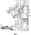
- FIG. 5is an enlarged section view of a central portion of the gaming machine shown in FIG. 1 in the direction of arrows 3 - 3 in FIG. 1 .
- FIG. 6is a section view similar to FIG. 5 , but showing a first video monitor in an open position.
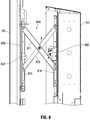
- FIG. 7is a section view similar to FIG. 5 , but showing a panel component in an open position.
- FIG. 8is an enlarged section view of an upper portion of the gaming machine shown in FIG. 1 in the direction of arrows 3 - 3 in FIG. 1 , but showing a second video monitor in an open position.
- an example gaming machine 100includes a gaming machine cabinet 101 on which is mounted a first video display monitor 104 and a second video display monitor 105 .
- Gaming machine 100further includes a panel 107 containing or providing access to several player interface devices 108 immediately below first video display monitor 104 .
- a button deck 110is also mounted on gaming machine cabinet 101 protruding from a front of the cabinet immediately below panel 107 .
- Various player interface devicessuch as a physical button 112 and touchscreen control panel 114 are located on the illustrated button deck 110 .
- One or more removable or openable panels 116may be positioned at the front of the gaming machine cabinet below button deck 110 .
- gaming machine cabinet 101defines an upper cabinet volume shown by arrow 301 in FIG. 3 above the level of the button deck 110 .
- Gaming machine cabinet 101also includes a cabinet front opening (exposed in FIG. 2 ) to the upper cabinet volume 301 .
- the cabinet front openingis divided into two areas including a base area defined by opening 202 and a crown area defined by opening 203 .
- first video monitor 104is mounted in an upper portion of the base area of the cabinet front opening while panel 107 is mounted in a lower portion of the base area.
- FIG. 4is a view in section similar to FIG. 3 but from the opposite direction.
- certain components of the cabinet opening mechanismsare provided in pairs with the two components in each pair laterally spaced apart within the cabinet volume on opposite sides of the cabinet 101 .
- FIG. 3shows components of the cabinet opening mechanisms on one side of the cabinet (the left side in the orientation of FIG. 1 )
- FIG. 4shows components of the cabinet opening mechanisms on the opposite (right) side.
- FIG. 3shows certain components mounted in the center of gaming machine cabinet 101
- FIG. 4does not show these center-mounted components. This will be discussed further in connection with the enlarged views of FIGS. 5-8 .
- first video display monitor 104registers with and covers the upper portion of the base area of the cabinet front opening (the base area defined by opening 202 in FIG. 2 ).
- first video display monitor 104extends laterally across and covers the entire width dimension of the upper portion of opening 202 when the first video display monitor is in its operating position.
- panel 107registers with and covers the lower portion of the base area of the cabinet front opening. That is, panel 107 is shown as extending laterally across and covering the entire width dimension of the lower part of opening 202 .
- second video display monitor 105 in its operating positionregisters with and covers the crown area defined by opening 203 shown in FIG. 2 .
- first video display monitor 104is mounted on a first extension assembly shown generally at 501 in the figures.
- First extension assembly 501includes a pivot arm 502 with a monitor mounting bracket 504 located at a distal end of the pivot arm.
- First video display monitor 104 in this example configurationis connected to the first extension assembly via monitor mounting bracket 504 .
- a proximal end 503 of pivot arm 502is pivotally connected to gaming machine cabinet 101 so as to be pivotable about axis P which extends perpendicular to the plane of the drawing sheet in FIG. 5 and also perpendicular to a central vertical axis of the gaming machine cabinet shown in the figures as axis V.
- a hydraulic or pneumatic damper 508is connected between pivot arm 502 and gaming machine cabinet 101 to help support the weight of first video monitor 104 and extension assembly 501 when the first video monitor is moved to its open position as will be described further below.
- spring devicessuch as constant force springs may be included in the pivot connection between pivot arm 502 and gaming machine cabinet 101 to also help support the weight of first video monitor 104 and extension assembly 501 when the first video monitor is moved to its open position.
- a first video monitor latching mechanism 510is included to securely latch the first video monitor 104 in the operating position shown in FIG. 5 .
- Latching mechanism 510is operable to catch and retain a catch feature which is included on monitor bracket 504 in this embodiment. In the view of FIG. 5 , the catch feature extends on the opposite side of tab 512 and is thus not visible in this view.
- First video monitor latching mechanism 510is associated with a release mechanism (not shown) which may be operated to cause the latching mechanism to release the catch feature on tab 512 and thus release the secure connection of first video display monitor 104 in the operating position shown in FIG. 5 .
- An operator control to this release mechanismmay be accessible through an opening into the gaming machine cabinet interior volume covered by lower panel 116 .
- panel 107is connected to gaming machine cabinet 101 through a slide assembly.
- the slide assembly in this embodimentincludes a first side rail 520 a mounted substantially vertically on a first side of the gaming machine cabinet within the upper cabinet volume. This first side rail 520 a is also visible in the view of FIG. 2 .
- a second side rail 520 bis mounted substantially vertically on a second side of the gaming machine cabinet within the upper cabinet volume.
- the slide assemblyfurther includes a carriage assembly connected to both the first side rail 520 a and the second side rail 520 b for longitudinal movement with respect to each rail.
- the illustrated carriage assemblyincludes a first side carriage 522 a shown in FIG. 5 (also shown in FIG.
- the carriage assemblycan comprise a single element that extends the width of the cabinet interior volume and connects at each end to a respective side rail.
- the panel 107is mounted on this single carriage assembly component to facilitate the sliding movement described below.
- This single carriage structureis in contrast to the two separate carriage assembly components (first side carriage 522 a and 522 b ) indicated by the present figures.
- panel 107is connected at one end to first side carriage 522 a at one side of the cabinet and to second side carriage 522 b at the other side of the cabinet.
- Implementations of the inventionare not limited to any particular slidable connection between the carriage assembly, either the single component versions or the illustrated multiple component versions, and the two side rails to facilitate the desired longitudinal movement along the rails.
- Some implementationsmay include suitable rollers mounted on the carriage assembly on either side of the rail and cooperating with the rail to provide smooth longitudinal movement along the rail.
- each railmay comprise a cylindrically shaped element and the carriage assembly may include a cylindrically shaped bushing or other element received on the respective cylindrically shaped rail so as to facilitate the desired movement along the rails.
- FIG. 5also shows a carriage latching mechanism 524 positioned and adapted to cooperate with a feature 525 at a lower end of first side carriage 522 a to securely latch the first side carriage in the position shown in FIG. 5 in which panel 107 is in its operating position.
- a release mechanism(not shown) is associated with latching mechanism 524 to allow an operator to release the feature 525 and allow the carriage 522 a and panel 107 to be raised to its open position as will be described below.
- the carriage latch release mechanismis preferably accessible though the opening of the gaming machine covered by panel 116 in the lower portion of the gaming machine.
- a latching mechanismmay be associated with the carriage on each side of the gaming machine cabinet.
- FIG. 6shows first video display monitor 104 in an open position.
- first monitor latching mechanism 510has been released to release the catch feature on tab 512 , and an operator has pulled outwardly at the lower part of the video display monitor 104 to rotate pivot arm 502 clockwise about pivot axis P.
- this movement of the video display monitor 104 to its open positionremoves the monitor from the upper part of the base area but remains supported on the gaming machine cabinet via pivot arm 502 .
- Hydraulic or pneumatic damper 508may provide support for the first video display monitor and pivot arm assembly in the open position shown in FIG. 6 .
- Pivot arm 502includes an offset between the proximal end portion secured at pivot axis P and the remainder of the proximal end 503 . This offset is shown at “d” in FIGS. 5 and 6 . Also, pivot arm 502 includes a series of straight segments that combine to produce an overall concave curvature facing forward and upward in the orientation of FIG. 5 and upward in the orientation of FIG. 6 . This curvature and the offset d both facilitate a greater range of movement for first video display monitor 104 about pivot axis P.
- panel 107remains supported in its operating position while first video display monitor 104 is moved to its open position. Once first video display monitor 104 is moved to the open position shown in FIG. 6 , thus vacating the upper portion of the base area, panel 107 may be released from its operating position shown best in FIGS. 5 and 6 and moved upwardly on the carriage assembly including carriage 422 a and the cooperating carriage 522 b (shown in FIG. 4 ) ultimately to the panel open position shown in FIG. 7 . As is apparent by comparing FIGS. 6 and 7 , in the course of moving from the panel operating position shown in FIG. 6 to the panel open position shown in FIG.
- panel 107traverses at least some of the upper portion of the base area which was vacated by first video display monitor 104 when the display monitor was moved to its open position.
- gaming machine 100may be closed by first returning panel 107 to its operating position shown in FIGS. 5 and 6 , and then returning first video monitor 104 to its operating position shown in FIG. 5 .
- the latching mechanism, 510 and 524respectively, is preferably configured to automatically latch the respective catch feature to hold the video monitor 104 and panel 107 in the respective operating position.
- the illustrated form of the apparatusincludes a single pivot arm 502 mounted at or near a vertical centerline of cabinet 101 .
- Other implementations of the inventionmay include two pivot arms similar to arm 502 , with the two arms laterally spaced apart on each side of the gaming machine.
- second video display monitor 105is also mounted on the gaming machine cabinet 101 so that it may be moved to a respective open position to expose the crown area of the cabinet interior volume defined by opening 203 (shown in FIG. 2 ).
- gaming machine 100includes a second extension assembly connected between second video monitor 105 and gaming machine cabinet 101 .
- the second extension assemblyincludes a scissor mechanism having first and second side scissor mechanisms 804 and 805 , respectively, connected to second monitor mounting bracket 806 .
- scissor mechanism 804includes a first elongated member 811 and a second elongated member 812 connected at a pivot point S.
- the upper end of first member 811is rotatably connected to an upper part of monitor mounting bracket 806 while an upper end of second member 812 is rotatably connected to cabinet 101 within the interior volume of the gaming machine.
- a lower end of first member 811is connected to a slot 815 on bracket 806 while a lower end of second member 812 is mounted in a slot 816 formed on an element connected to the gaming machine cabinet 101 .
- Scissor mechanism 805 at the opposite side of cabinet 101 from mechanism scissor mechanism 804includes a similar structure although the various components are not numbered in FIGS.
- An upper monitor latching arrangementis included to secure the second video display monitor in the operating position shown in FIGS. 1, 3, and 4 .
- This latching arrangementincludes upper monitor latch mechanism 820 which cooperates with a catch pin 821 mounted on the monitor mounting bracket 806 .
- latch pin 821is received in latch mechanism 820 to retain the monitor in the desired operating position.
- Latch mechanism 820is associated with a release (not shown) that allows pin 821 to be released to allow second video display monitor 105 to move on the scissor mechanisms 804 and 805 from the operating position shown in FIGS. 1, 3, and 4 to the open position shown in FIG. 8 .
- the release mechanism for latching mechanism 820is preferably operable from a point in the bottom part of the gaming machine interior volume accessible through the opening covered by panel 116 .
- eachmay be used in the following claims for convenience in describing characteristics or features of multiple elements, and any such use of the term “each” is in the inclusive sense unless specifically stated otherwise. For example, if a claim defines two or more elements as “each” having a characteristic or feature, the use of the term “each” is not intended to exclude from the claim scope a situation having a third one of the elements which does not have the defined characteristic or feature.
Landscapes
- Physics & Mathematics (AREA)
- General Physics & Mathematics (AREA)
- Slot Machines And Peripheral Devices (AREA)
Abstract
Description
Claims (20)
Priority Applications (1)
| Application Number | Priority Date | Filing Date | Title |
|---|---|---|---|
| US16/115,537US10825286B2 (en) | 2017-09-30 | 2018-08-28 | Gaming machine cabinet with multiple panel access structure |
Applications Claiming Priority (2)
| Application Number | Priority Date | Filing Date | Title |
|---|---|---|---|
| US201762566411P | 2017-09-30 | 2017-09-30 | |
| US16/115,537US10825286B2 (en) | 2017-09-30 | 2018-08-28 | Gaming machine cabinet with multiple panel access structure |
Publications (2)
| Publication Number | Publication Date |
|---|---|
| US20190102983A1 US20190102983A1 (en) | 2019-04-04 |
| US10825286B2true US10825286B2 (en) | 2020-11-03 |
Family
ID=65896813
Family Applications (1)
| Application Number | Title | Priority Date | Filing Date |
|---|---|---|---|
| US16/115,537Active2038-12-10US10825286B2 (en) | 2017-09-30 | 2018-08-28 | Gaming machine cabinet with multiple panel access structure |
Country Status (1)
| Country | Link |
|---|---|
| US (1) | US10825286B2 (en) |
Cited By (12)
| Publication number | Priority date | Publication date | Assignee | Title |
|---|---|---|---|---|
| US20210110642A1 (en)* | 2019-10-11 | 2021-04-15 | Konami Gaming, Inc. | Gaming machine and modular cabinet system for use with gaming machines |
| US11004301B2 (en)* | 2016-12-29 | 2021-05-11 | Video Gaming Technologies, Inc. | Gaming machine including display |
| USD952749S1 (en)* | 2018-10-03 | 2022-05-24 | Sg Gaming, Inc. | Gaming machine |
| US20230045373A1 (en)* | 2021-07-29 | 2023-02-09 | Aristocrat Technologies, Inc. | Bill validator mount for electronic gaming machines |
| US20240005725A1 (en)* | 2022-06-29 | 2024-01-04 | Everi Games Inc. | Gaming machine cabinet compartment with front access structure |
| USD1019785S1 (en) | 2018-08-03 | 2024-03-26 | Aristocrat Technologies, Inc. | Gaming machine |
| US11941939B2 (en) | 2020-09-24 | 2024-03-26 | Aristocrat Technologies, Inc. | Electronic gaming machine including monitor and podium counterweight |
| US11954964B2 (en) | 2020-05-05 | 2024-04-09 | Aristocrat Technologies, Inc. | Electronic gaming machine with access door |
| USD1040551S1 (en) | 2021-03-18 | 2024-09-03 | Aristocrat Technologies, Inc. | Gaming machine bench |
| US12214285B2 (en) | 2021-09-30 | 2025-02-04 | Aristocrat Technologies, Inc. | Door locking assembly for a button deck of an electronic gaming machine |
| USD1077916S1 (en) | 2018-08-03 | 2025-06-03 | Aristocrat Technologies Australia Pty Limited | Gaming machine |
| US12444265B2 (en) | 2024-03-06 | 2025-10-14 | Aristocrat Technologies, Inc. | Electronic gaming machine with access door |
Families Citing this family (23)
| Publication number | Priority date | Publication date | Assignee | Title |
|---|---|---|---|---|
| USD820915S1 (en) | 2015-09-22 | 2018-06-19 | Ags Llc | Gaming machine |
| USD813954S1 (en) | 2015-09-24 | 2018-03-27 | Ags Llc | Game tower |
| USD818048S1 (en) | 2015-10-05 | 2018-05-15 | Ags Llc | Gaming machine |
| US9997010B2 (en) | 2015-12-18 | 2018-06-12 | Ags Llc | Electronic gaming device with external lighting functionality |
| US10002488B2 (en) | 2015-12-17 | 2018-06-19 | Ags Llc | Electronic gaming device with call tower functionality |
| USD843473S1 (en) | 2017-04-07 | 2019-03-19 | Ags Llc | Gaming machine |
| USD880604S1 (en) | 2017-09-15 | 2020-04-07 | Aristocrat Technologies Australia Pty Limited | Gaming machine |
| USD902319S1 (en)* | 2017-09-20 | 2020-11-17 | Ags Llc | Community display for gaming machines |
| USD889553S1 (en)* | 2017-09-28 | 2020-07-07 | Sg Gaming, Inc. | Gaming terminal |
| USD915523S1 (en) | 2017-09-28 | 2021-04-06 | Sg Gaming, Inc. | Gaming terminal |
| USD889552S1 (en)* | 2017-09-28 | 2020-07-07 | Sg Gaming, Inc. | Gaming terminal |
| USD887496S1 (en) | 2017-09-29 | 2020-06-16 | Aristocrat Technologies Australia Pty Limited | Gaming machine display |
| USD852890S1 (en) | 2017-11-30 | 2019-07-02 | Ags Llc | Gaming machine |
| US10506730B2 (en)* | 2018-04-13 | 2019-12-10 | Aristocrat Technologies Australia Pty Limited | Overhead display assembly and method for electronic gaming machines |
| USD948620S1 (en)* | 2018-10-04 | 2022-04-12 | Aristocrat Technologies Australia Pty Limited | Gaming machine |
| USD911451S1 (en)* | 2018-10-05 | 2021-02-23 | Zitro Ip S.À.R.L. | Gaming machine |
| US10755519B2 (en) | 2018-10-07 | 2020-08-25 | Everi Games, Inc. | Gaming machine with dual translation front access structure |
| USD998046S1 (en) | 2019-08-16 | 2023-09-05 | Nano Vo Sp. Z.O.O. | Machine for game of chance |
| USD991356S1 (en)* | 2020-12-07 | 2023-07-04 | Nano Vo Sp. Zo.O. | Automatic machine for game of chance |
| USD987725S1 (en)* | 2021-06-03 | 2023-05-30 | Zitro International S.Àr.L | Amusement apparatus |
| US12169996B2 (en)* | 2021-07-21 | 2024-12-17 | Konami Gaming, Inc. | Gaming machine and display lifting system for use with gaming machines |
| USD1074821S1 (en) | 2022-03-16 | 2025-05-13 | Aristocrat Technologies, Inc. | Gaming machine with card reader |
| US20240013611A1 (en)* | 2022-04-19 | 2024-01-11 | Ags Llc | Gaming machine cabinet |
Citations (12)
| Publication number | Priority date | Publication date | Assignee | Title |
|---|---|---|---|---|
| GB2388696A (en)* | 2003-02-18 | 2003-11-19 | Ling Wen Chen | Game device having an openable front panel |
| US20060205504A1 (en)* | 2005-01-21 | 2006-09-14 | Aruze Corp. | Gaming machine |
| US20060287112A1 (en)* | 2005-06-15 | 2006-12-21 | Mallory Chester L | Gaming machine with a coin collector |
| US20080055491A1 (en)* | 2006-02-06 | 2008-03-06 | Spielo Manufacturing Ulc. | Cabinet with movable video screen |
| US20080113796A1 (en)* | 2006-11-09 | 2008-05-15 | Igt | Speaker arrangement and control on a gaming machine |
| US20100120530A1 (en)* | 2008-11-10 | 2010-05-13 | Wms Gaming Inc | Adjustable playing area for electronic gaming terminal |
| US20100124994A1 (en)* | 2008-11-17 | 2010-05-20 | O'keene Dugan S | Gaming Cabinet |
| US8366555B2 (en)* | 2006-11-10 | 2013-02-05 | Igt | Rotating quick release button panel |
| US20160184716A1 (en)* | 2012-12-14 | 2016-06-30 | Novomatic Ag | Gaming device comprising a vertical housing |
| US20160343204A1 (en)* | 2015-05-20 | 2016-11-24 | Wms Gaming Inc. | Floating pivot point hinge for a wagering game cabinet door |
| US9697679B2 (en)* | 2015-09-02 | 2017-07-04 | Entropy Precision System Inc. | Gaming machine having liftable monitor |
| US20180053373A1 (en)* | 2016-08-18 | 2018-02-22 | Bally Gaming, Inc. | Externally hinged cabinet door for a gaming machine housing |
- 2018
- 2018-08-28USUS16/115,537patent/US10825286B2/enactiveActive
Patent Citations (12)
| Publication number | Priority date | Publication date | Assignee | Title |
|---|---|---|---|---|
| GB2388696A (en)* | 2003-02-18 | 2003-11-19 | Ling Wen Chen | Game device having an openable front panel |
| US20060205504A1 (en)* | 2005-01-21 | 2006-09-14 | Aruze Corp. | Gaming machine |
| US20060287112A1 (en)* | 2005-06-15 | 2006-12-21 | Mallory Chester L | Gaming machine with a coin collector |
| US20080055491A1 (en)* | 2006-02-06 | 2008-03-06 | Spielo Manufacturing Ulc. | Cabinet with movable video screen |
| US20080113796A1 (en)* | 2006-11-09 | 2008-05-15 | Igt | Speaker arrangement and control on a gaming machine |
| US8366555B2 (en)* | 2006-11-10 | 2013-02-05 | Igt | Rotating quick release button panel |
| US20100120530A1 (en)* | 2008-11-10 | 2010-05-13 | Wms Gaming Inc | Adjustable playing area for electronic gaming terminal |
| US20100124994A1 (en)* | 2008-11-17 | 2010-05-20 | O'keene Dugan S | Gaming Cabinet |
| US20160184716A1 (en)* | 2012-12-14 | 2016-06-30 | Novomatic Ag | Gaming device comprising a vertical housing |
| US20160343204A1 (en)* | 2015-05-20 | 2016-11-24 | Wms Gaming Inc. | Floating pivot point hinge for a wagering game cabinet door |
| US9697679B2 (en)* | 2015-09-02 | 2017-07-04 | Entropy Precision System Inc. | Gaming machine having liftable monitor |
| US20180053373A1 (en)* | 2016-08-18 | 2018-02-22 | Bally Gaming, Inc. | Externally hinged cabinet door for a gaming machine housing |
Cited By (20)
| Publication number | Priority date | Publication date | Assignee | Title |
|---|---|---|---|---|
| US11004301B2 (en)* | 2016-12-29 | 2021-05-11 | Video Gaming Technologies, Inc. | Gaming machine including display |
| USD1077916S1 (en) | 2018-08-03 | 2025-06-03 | Aristocrat Technologies Australia Pty Limited | Gaming machine |
| USD1019785S1 (en) | 2018-08-03 | 2024-03-26 | Aristocrat Technologies, Inc. | Gaming machine |
| USD952749S1 (en)* | 2018-10-03 | 2022-05-24 | Sg Gaming, Inc. | Gaming machine |
| US11544992B2 (en)* | 2019-10-11 | 2023-01-03 | Konami Gaming, Inc. | Gaming machine and modular cabinet system for use with gaming machines |
| US20230177913A1 (en)* | 2019-10-11 | 2023-06-08 | Konami Gaming, Inc. | Gaming machine and modular cabinet system for use with gaming machines |
| US20210110642A1 (en)* | 2019-10-11 | 2021-04-15 | Konami Gaming, Inc. | Gaming machine and modular cabinet system for use with gaming machines |
| US12033458B2 (en)* | 2019-10-11 | 2024-07-09 | Konami Gaming, Inc. | Gaming machine and modular cabinet system for use with gaming machines |
| US11954964B2 (en) | 2020-05-05 | 2024-04-09 | Aristocrat Technologies, Inc. | Electronic gaming machine with access door |
| US12175829B2 (en) | 2020-09-24 | 2024-12-24 | Aristocrat Technologies, Inc. | Mounting assembly for an electronic gaming machine |
| US11941939B2 (en) | 2020-09-24 | 2024-03-26 | Aristocrat Technologies, Inc. | Electronic gaming machine including monitor and podium counterweight |
| US12165463B2 (en) | 2020-09-24 | 2024-12-10 | Aristocrat Technologies, Inc. | Lift assembly and mount for a monitor of an electronic gaming machine |
| USD1040551S1 (en) | 2021-03-18 | 2024-09-03 | Aristocrat Technologies, Inc. | Gaming machine bench |
| US11995938B2 (en)* | 2021-07-29 | 2024-05-28 | Aristocrat Technologies, Inc. (ATI) | Bill validator mount for electronic gaming machines |
| US20230045373A1 (en)* | 2021-07-29 | 2023-02-09 | Aristocrat Technologies, Inc. | Bill validator mount for electronic gaming machines |
| US12322235B2 (en) | 2021-07-29 | 2025-06-03 | Aristocrat Technologies, Inc. | Bill validator mount for electronic gaming machines |
| US12214285B2 (en) | 2021-09-30 | 2025-02-04 | Aristocrat Technologies, Inc. | Door locking assembly for a button deck of an electronic gaming machine |
| US12087125B2 (en)* | 2022-06-29 | 2024-09-10 | Everi Games Inc. | Gaming machine cabinet compartment with front access structure |
| US20240005725A1 (en)* | 2022-06-29 | 2024-01-04 | Everi Games Inc. | Gaming machine cabinet compartment with front access structure |
| US12444265B2 (en) | 2024-03-06 | 2025-10-14 | Aristocrat Technologies, Inc. | Electronic gaming machine with access door |
Also Published As
| Publication number | Publication date |
|---|---|
| US20190102983A1 (en) | 2019-04-04 |
Similar Documents
| Publication | Publication Date | Title |
|---|---|---|
| US10825286B2 (en) | Gaming machine cabinet with multiple panel access structure | |
| US11631296B2 (en) | Gaming machine cabinet access structure and method | |
| US10755519B2 (en) | Gaming machine with dual translation front access structure | |
| US12169996B2 (en) | Gaming machine and display lifting system for use with gaming machines | |
| US8851989B2 (en) | Method and apparatus for hinging and hanging a gaming machine door | |
| US11380157B2 (en) | Servicing and mounting features for gaming machine display screens and toppers | |
| US7267613B2 (en) | Slant-type gaming machine | |
| US8439761B2 (en) | Gaming cabinet with a gaming deck capable of being slid away from the display and rotated in either upward or downward directions | |
| US20080087521A1 (en) | Gaming device with a vertically translating currency acceptor | |
| JP3306027B2 (en) | Winning device | |
| JP2014158926A (en) | Game machine | |
| JP4386445B2 (en) | Game machine | |
| JP6538523B2 (en) | Gaming device | |
| JP6343868B2 (en) | Game machine | |
| JP5575204B2 (en) | Game machine | |
| US9386853B2 (en) | Cabinet drawer stop mechanism | |
| JP6343867B2 (en) | Game machine | |
| JP6249264B2 (en) | Game machine | |
| JP3640938B2 (en) | Separate slot machine | |
| JP2012143394A (en) | Game device | |
| JP2005111031A (en) | Game machine | |
| JP6372720B2 (en) | Game machine | |
| JP5806763B2 (en) | Game machine | |
| AU2025238037A1 (en) | Signage layered display monitors | |
| JP2019188050A (en) | Game machine |
Legal Events
| Date | Code | Title | Description |
|---|---|---|---|
| FEPP | Fee payment procedure | Free format text:ENTITY STATUS SET TO UNDISCOUNTED (ORIGINAL EVENT CODE: BIG.); ENTITY STATUS OF PATENT OWNER: LARGE ENTITY | |
| AS | Assignment | Owner name:EVERI GAMES INC., TEXAS Free format text:ASSIGNMENT OF ASSIGNORS INTEREST;ASSIGNORS:GALLAGHER, CRAIG STEVEN;PHILLIPS, PETER A.;BUSSEY, TRAVIS B.;SIGNING DATES FROM 20180810 TO 20180813;REEL/FRAME:047398/0977 | |
| STPP | Information on status: patent application and granting procedure in general | Free format text:DOCKETED NEW CASE - READY FOR EXAMINATION | |
| AS | Assignment | Owner name:JEFFERIES FINANCE LLC, NEW YORK Free format text:SECURITY INTEREST;ASSIGNOR:EVERI PAYMENTS INC;REEL/FRAME:048774/0525 Effective date:20190329 | |
| AS | Assignment | Owner name:JEFFERIES FINANCE LLC, AS COLLATERAL AGENT, NEW YORK Free format text:PATENT SECURITY AGREEMENT;ASSIGNORS:EVERI HOLDINGS INC.;EVERI PAYMENTS INC.;GCA MTL, LLC;AND OTHERS;REEL/FRAME:052494/0463 Effective date:20200421 | |
| STPP | Information on status: patent application and granting procedure in general | Free format text:NOTICE OF ALLOWANCE MAILED -- APPLICATION RECEIVED IN OFFICE OF PUBLICATIONS | |
| STPP | Information on status: patent application and granting procedure in general | Free format text:PUBLICATIONS -- ISSUE FEE PAYMENT VERIFIED | |
| STCF | Information on status: patent grant | Free format text:PATENTED CASE | |
| AS | Assignment | Owner name:EVERI PAYMENTS INC., NEVADA Free format text:RELEASE BY SECURED PARTY;ASSIGNOR:JEFFERIES FINANCE LLC;REEL/FRAME:057110/0905 Effective date:20210803 Owner name:EVERY PAYMENTS INC., NEVADA Free format text:RELEASE BY SECURED PARTY;ASSIGNOR:JEFFERIES FIANANCE LLC;REEL/FRAME:057111/0001 Effective date:20210803 Owner name:EVERI HOLDINGS INC., NEVADA Free format text:RELEASE BY SECURED PARTY;ASSIGNOR:JEFFERIES FIANANCE LLC;REEL/FRAME:057111/0001 Effective date:20210803 Owner name:EVERI GAMES HOLDING INC., NEVADA Free format text:RELEASE BY SECURED PARTY;ASSIGNOR:JEFFERIES FIANANCE LLC;REEL/FRAME:057111/0001 Effective date:20210803 Owner name:GCA MTL, LLC, NEVADA Free format text:RELEASE BY SECURED PARTY;ASSIGNOR:JEFFERIES FIANANCE LLC;REEL/FRAME:057111/0001 Effective date:20210803 Owner name:CENTRAL CREDIT, LLC, NEVADA Free format text:RELEASE BY SECURED PARTY;ASSIGNOR:JEFFERIES FIANANCE LLC;REEL/FRAME:057111/0001 Effective date:20210803 Owner name:EVERI INTERACTIVE LLC, NEVADA Free format text:RELEASE BY SECURED PARTY;ASSIGNOR:JEFFERIES FIANANCE LLC;REEL/FRAME:057111/0001 Effective date:20210803 Owner name:EVERI GAMES INC., NEVADA Free format text:RELEASE BY SECURED PARTY;ASSIGNOR:JEFFERIES FIANANCE LLC;REEL/FRAME:057111/0001 Effective date:20210803 | |
| AS | Assignment | Owner name:EVERI PAYMENTS INC., NEVADA Free format text:CORRECTIVE ASSIGNMENT TO CORRECT THE ASSIGNOR'S NAME AND THE FIRST ASSIGNEE'S NAME PREVIOUSLY RECORDED AT REEL: 057111 FRAME: 0001. ASSIGNOR(S) HEREBY CONFIRMS THE RELEASE OF SECURITY INTEREST;ASSIGNOR:JEFFERIES FINANCE LLC;REEL/FRAME:057184/0244 Effective date:20210803 Owner name:EVERI HOLDINGS INC., NEVADA Free format text:CORRECTIVE ASSIGNMENT TO CORRECT THE ASSIGNOR'S NAME AND THE FIRST ASSIGNEE'S NAME PREVIOUSLY RECORDED AT REEL: 057111 FRAME: 0001. ASSIGNOR(S) HEREBY CONFIRMS THE RELEASE OF SECURITY INTEREST;ASSIGNOR:JEFFERIES FINANCE LLC;REEL/FRAME:057184/0244 Effective date:20210803 Owner name:EVERI GAMES HOLDING INC., NEVADA Free format text:CORRECTIVE ASSIGNMENT TO CORRECT THE ASSIGNOR'S NAME AND THE FIRST ASSIGNEE'S NAME PREVIOUSLY RECORDED AT REEL: 057111 FRAME: 0001. ASSIGNOR(S) HEREBY CONFIRMS THE RELEASE OF SECURITY INTEREST;ASSIGNOR:JEFFERIES FINANCE LLC;REEL/FRAME:057184/0244 Effective date:20210803 Owner name:GCA MTL, LLC, NEVADA Free format text:CORRECTIVE ASSIGNMENT TO CORRECT THE ASSIGNOR'S NAME AND THE FIRST ASSIGNEE'S NAME PREVIOUSLY RECORDED AT REEL: 057111 FRAME: 0001. ASSIGNOR(S) HEREBY CONFIRMS THE RELEASE OF SECURITY INTEREST;ASSIGNOR:JEFFERIES FINANCE LLC;REEL/FRAME:057184/0244 Effective date:20210803 Owner name:CENTRAL CREDIT, LLC, NEVADA Free format text:CORRECTIVE ASSIGNMENT TO CORRECT THE ASSIGNOR'S NAME AND THE FIRST ASSIGNEE'S NAME PREVIOUSLY RECORDED AT REEL: 057111 FRAME: 0001. ASSIGNOR(S) HEREBY CONFIRMS THE RELEASE OF SECURITY INTEREST;ASSIGNOR:JEFFERIES FINANCE LLC;REEL/FRAME:057184/0244 Effective date:20210803 Owner name:EVERI INTERACTIVE LLC, NEVADA Free format text:CORRECTIVE ASSIGNMENT TO CORRECT THE ASSIGNOR'S NAME AND THE FIRST ASSIGNEE'S NAME PREVIOUSLY RECORDED AT REEL: 057111 FRAME: 0001. ASSIGNOR(S) HEREBY CONFIRMS THE RELEASE OF SECURITY INTEREST;ASSIGNOR:JEFFERIES FINANCE LLC;REEL/FRAME:057184/0244 Effective date:20210803 Owner name:EVERI GAMES INC., NEVADA Free format text:CORRECTIVE ASSIGNMENT TO CORRECT THE ASSIGNOR'S NAME AND THE FIRST ASSIGNEE'S NAME PREVIOUSLY RECORDED AT REEL: 057111 FRAME: 0001. ASSIGNOR(S) HEREBY CONFIRMS THE RELEASE OF SECURITY INTEREST;ASSIGNOR:JEFFERIES FINANCE LLC;REEL/FRAME:057184/0244 Effective date:20210803 | |
| AS | Assignment | Owner name:JEFFERIES FINANCE LLC, AS COLLATERAL AGENT, NEW YORK Free format text:PATENT SECURITY AGREEMENT (SHORT-FORM);ASSIGNOR:EVERI HOLDINGS INC.;REEL/FRAME:058948/0265 Effective date:20210803 | |
| MAFP | Maintenance fee payment | Free format text:PAYMENT OF MAINTENANCE FEE, 4TH YEAR, LARGE ENTITY (ORIGINAL EVENT CODE: M1551); ENTITY STATUS OF PATENT OWNER: LARGE ENTITY Year of fee payment:4 | |
| AS | Assignment | Owner name:EVERI HOLDINGS INC., NEVADA Free format text:TERMINATION AND RELEASE OF PATENT SECURITY AGREEMENT RECORDED AT REEL 058948, FRAME 0265;ASSIGNOR:JEFFERIES FINANCE LLC, AS COLLATERAL AGENT;REEL/FRAME:071791/0236 Effective date:20250701 | |
| AS | Assignment | Owner name:DEUTSCHE BANK AG NEW YORK BRANCH, AS COLLATERAL AGENT, NEW YORK Free format text:SECURITY AGREEMENT;ASSIGNORS:EVERI GAMES INC.;EVERI PAYMENTS INC.;REEL/FRAME:071827/0315 Effective date:20250701 |