US10825263B2 - Advanced discrete control device diagnostic on digital output modules - Google Patents
Advanced discrete control device diagnostic on digital output modulesDownload PDFInfo
- Publication number
- US10825263B2 US10825263B2US15/615,562US201715615562AUS10825263B2US 10825263 B2US10825263 B2US 10825263B2US 201715615562 AUS201715615562 AUS 201715615562AUS 10825263 B2US10825263 B2US 10825263B2
- Authority
- US
- United States
- Prior art keywords
- digital
- output module
- input
- digital output
- output current
- Prior art date
- Legal status (The legal status is an assumption and is not a legal conclusion. Google has not performed a legal analysis and makes no representation as to the accuracy of the status listed.)
- Active, expires
Links
Images


Classifications
- G—PHYSICS
- G08—SIGNALLING
- G08B—SIGNALLING OR CALLING SYSTEMS; ORDER TELEGRAPHS; ALARM SYSTEMS
- G08B21/00—Alarms responsive to a single specified undesired or abnormal condition and not otherwise provided for
- G08B21/18—Status alarms
- G—PHYSICS
- G01—MEASURING; TESTING
- G01R—MEASURING ELECTRIC VARIABLES; MEASURING MAGNETIC VARIABLES
- G01R31/00—Arrangements for testing electric properties; Arrangements for locating electric faults; Arrangements for electrical testing characterised by what is being tested not provided for elsewhere
- G01R31/28—Testing of electronic circuits, e.g. by signal tracer
- G01R31/282—Testing of electronic circuits specially adapted for particular applications not provided for elsewhere
- G—PHYSICS
- G01—MEASURING; TESTING
- G01R—MEASURING ELECTRIC VARIABLES; MEASURING MAGNETIC VARIABLES
- G01R31/00—Arrangements for testing electric properties; Arrangements for locating electric faults; Arrangements for electrical testing characterised by what is being tested not provided for elsewhere
- G01R31/28—Testing of electronic circuits, e.g. by signal tracer
- G01R31/3167—Testing of combined analog and digital circuits
- G—PHYSICS
- G01—MEASURING; TESTING
- G01R—MEASURING ELECTRIC VARIABLES; MEASURING MAGNETIC VARIABLES
- G01R31/00—Arrangements for testing electric properties; Arrangements for locating electric faults; Arrangements for electrical testing characterised by what is being tested not provided for elsewhere
- G01R31/50—Testing of electric apparatus, lines, cables or components for short-circuits, continuity, leakage current or incorrect line connections
- G01R31/56—Testing of electric apparatus
- G—PHYSICS
- G06—COMPUTING OR CALCULATING; COUNTING
- G06F—ELECTRIC DIGITAL DATA PROCESSING
- G06F11/00—Error detection; Error correction; Monitoring
- G—PHYSICS
- G06—COMPUTING OR CALCULATING; COUNTING
- G06F—ELECTRIC DIGITAL DATA PROCESSING
- G06F11/00—Error detection; Error correction; Monitoring
- G06F11/07—Responding to the occurrence of a fault, e.g. fault tolerance
- G—PHYSICS
- G06—COMPUTING OR CALCULATING; COUNTING
- G06F—ELECTRIC DIGITAL DATA PROCESSING
- G06F11/00—Error detection; Error correction; Monitoring
- G06F11/30—Monitoring
- G06F11/3003—Monitoring arrangements specially adapted to the computing system or computing system component being monitored
- G06F11/3013—Monitoring arrangements specially adapted to the computing system or computing system component being monitored where the computing system is an embedded system, i.e. a combination of hardware and software dedicated to perform a certain function in mobile devices, printers, automotive or aircraft systems
- G—PHYSICS
- G06—COMPUTING OR CALCULATING; COUNTING
- G06F—ELECTRIC DIGITAL DATA PROCESSING
- G06F11/00—Error detection; Error correction; Monitoring
- G06F11/30—Monitoring
- G06F11/3058—Monitoring arrangements for monitoring environmental properties or parameters of the computing system or of the computing system component, e.g. monitoring of power, currents, temperature, humidity, position, vibrations
- G—PHYSICS
- G07—CHECKING-DEVICES
- G07C—TIME OR ATTENDANCE REGISTERS; REGISTERING OR INDICATING THE WORKING OF MACHINES; GENERATING RANDOM NUMBERS; VOTING OR LOTTERY APPARATUS; ARRANGEMENTS, SYSTEMS OR APPARATUS FOR CHECKING NOT PROVIDED FOR ELSEWHERE
- G07C3/00—Registering or indicating the condition or the working of machines or other apparatus, other than vehicles
- G07C3/005—Registering or indicating the condition or the working of machines or other apparatus, other than vehicles during manufacturing process
- G—PHYSICS
- G08—SIGNALLING
- G08B—SIGNALLING OR CALLING SYSTEMS; ORDER TELEGRAPHS; ALARM SYSTEMS
- G08B21/00—Alarms responsive to a single specified undesired or abnormal condition and not otherwise provided for
- G08B21/18—Status alarms
- G08B21/182—Level alarms, e.g. alarms responsive to variables exceeding a threshold
- G—PHYSICS
- G01—MEASURING; TESTING
- G01R—MEASURING ELECTRIC VARIABLES; MEASURING MAGNETIC VARIABLES
- G01R31/00—Arrangements for testing electric properties; Arrangements for locating electric faults; Arrangements for electrical testing characterised by what is being tested not provided for elsewhere
- G01R31/28—Testing of electronic circuits, e.g. by signal tracer
- G01R31/2801—Testing of printed circuits, backplanes, motherboards, hybrid circuits or carriers for multichip packages [MCP]
- G01R31/281—Specific types of tests or tests for a specific type of fault, e.g. thermal mapping, shorts testing
- G01R31/2812—Checking for open circuits or shorts, e.g. solder bridges; Testing conductivity, resistivity or impedance
- G—PHYSICS
- G01—MEASURING; TESTING
- G01R—MEASURING ELECTRIC VARIABLES; MEASURING MAGNETIC VARIABLES
- G01R31/00—Arrangements for testing electric properties; Arrangements for locating electric faults; Arrangements for electrical testing characterised by what is being tested not provided for elsewhere
- G01R31/50—Testing of electric apparatus, lines, cables or components for short-circuits, continuity, leakage current or incorrect line connections
- G—PHYSICS
- G06—COMPUTING OR CALCULATING; COUNTING
- G06F—ELECTRIC DIGITAL DATA PROCESSING
- G06F2201/00—Indexing scheme relating to error detection, to error correction, and to monitoring
- G06F2201/81—Threshold
- G—PHYSICS
- G07—CHECKING-DEVICES
- G07C—TIME OR ATTENDANCE REGISTERS; REGISTERING OR INDICATING THE WORKING OF MACHINES; GENERATING RANDOM NUMBERS; VOTING OR LOTTERY APPARATUS; ARRANGEMENTS, SYSTEMS OR APPARATUS FOR CHECKING NOT PROVIDED FOR ELSEWHERE
- G07C3/00—Registering or indicating the condition or the working of machines or other apparatus, other than vehicles
- G07C3/14—Quality control systems
- G—PHYSICS
- G08—SIGNALLING
- G08B—SIGNALLING OR CALLING SYSTEMS; ORDER TELEGRAPHS; ALARM SYSTEMS
- G08B21/00—Alarms responsive to a single specified undesired or abnormal condition and not otherwise provided for
- G08B21/18—Status alarms
- G08B21/187—Machine fault alarms
Definitions
- This disclosurerelates generally to diagnostics for devices in industrial process control and automation systems or other systems. More specifically, this disclosure relates to device diagnostics based on signals from digital outputs.
- Industrial process control and automation systemsare often used to automate and operate large and complex industrial processes. These types of systems routinely include sensors, actuators, and other field devices that can measure, adjust, or otherwise monitor or interact with one or more industrial processes. Diagnostic information related to field devices can be very useful in an industrial control and automation environment or other environment, such as to detect abnormal or faulty operation of field devices. Some field devices support the use of one or more digital outputs, each of which can provide a digital output signal. Conventionally, digital outputs come with only basic diagnostic capabilities, such as the ability to detect open-circuit and short-circuit conditions.
- This disclosureprovides device diagnostics based on signals from digital outputs.
- a methodin a first embodiment, includes measuring one or more characteristics of a digital signal provided by a digital output module, the digital output module coupled to a device, at least one of the one or more characteristics of the digital signal associated with an output current of the digital output module. The method further includes performing one or more diagnostics using the one or more measured characteristics of the digital signal.
- an apparatusin a second embodiment, includes an input/output module with a digital output module configured to be coupled to a device.
- the input/output moduleis configured to measure one or more characteristics of a digital signal provided by the digital output module, where at least one of the one or more characteristics of the digital signal is associated with an output current of the digital output module.
- the input/output moduleis also configured to perform one or more diagnostics using the one or more measured characteristics of the digital signal.
- a non-transitory machine-readable mediumis provided.
- the non-transitory machine-readable mediumis encoded with executable instructions that, when executed, cause one or more processors to measure one or more characteristics of a digital signal provided by the digital output module, wherein at least one of the one or more characteristics of the digital signal associated with an output current of the digital output module and perform one or more diagnostics using the one or more measured characteristics of the digital signal.
- FIG. 1illustrates an example industrial process control and automation system according to this disclosure
- FIG. 2illustrates an example digital output module for a device according to this disclosure
- FIG. 3illustrates a specific example of a universal input/output (UIO) module supporting device diagnostics according to this disclosure
- FIGS. 4 and 5illustrate example types of diagnostics that can be performed for a device using a digital output according to this disclosure
- FIG. 6illustrates an example system for device diagnostics using a digital output according to this disclosure
- FIG. 7illustrates a process for performing device diagnostics from signals on digital outputs according to this disclosure.
- FIGS. 8, 9 and 10illustrate example processes for performing digital output current diagnostics according to this disclosure.
- FIGS. 1 through 10discussed below, and the various embodiments used to describe the principles of the present invention in this patent document are by way of illustration only and should not be construed in any way to limit the scope of the invention. Those skilled in the art will understand that the principles of the invention may be implemented in any type of suitably arranged device or system.
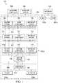
- FIG. 1illustrates an example industrial process control and automation system 100 according to this disclosure.
- the system 100includes various components that facilitate production or processing of at least one product or other material.
- the system 100is used here to facilitate control over components in one or multiple plants 101 a - 101 n .
- Each plant 101 a - 101 nrepresents one or more processing facilities (or one or more portions thereof), such as one or more manufacturing facilities for producing at least one product or other material.
- each plant 101 a - 101 nmay implement one or more processes and can individually or collectively be referred to as a process system.
- a process systemgenerally represents any system or portion thereof configured to process one or more products or other materials in some manner.
- Level 0may include one or more sensors 102 a and one or more actuators 102 b .
- the sensors 102 a and actuators 102 brepresent components in a process system that may perform any of a wide variety of functions.
- the sensors 102 acould measure a wide variety of characteristics in the process system, such as temperature, pressure, or flow rate.
- the actuators 102 bcould alter a wide variety of characteristics in the process system.
- the sensors 102 a and actuators 102 bcould represent any other or additional components in any suitable process system.
- Each of the sensors 102 aincludes any suitable structure for measuring one or more characteristics in a process system.
- Each of the actuators 102 bincludes any suitable structure for operating on or affecting one or more conditions in a process system.
- One or more networks 104are coupled to the sensors 102 a and actuators 102 b .
- the network 104facilitates interaction with the sensors 102 a and actuators 102 b .
- the network 104could transport measurement data from the sensors 102 a and provide control signals to the actuators 102 b .
- the network 104could represent any suitable network or combination of networks.
- the network 104could represent an Ethernet network, an electrical signal network (such as a HART or FOUNDATION FIELDBUS network), a pneumatic control signal network, or any other or additional type(s) of network(s).
- Level 1includes one or more controllers 106 , which are coupled to the network 104 .
- each controller 106may use the measurements from one or more sensors 102 a to control the operation of one or more actuators 102 b .
- Each controller 106includes any suitable structure for controlling one or more aspects of a process system. As a particular example, each controller 106 could represent a computing device running a real-time operating system.
- Redundant networks 108are coupled to the controllers 106 .
- the networks 108facilitate interaction with the controllers 106 , such as by transporting data to and from the controllers 106 .
- the networks 108could represent any suitable redundant networks.
- the networks 108could represent a pair of Ethernet networks or a redundant pair of Ethernet networks, such as a FAULT TOLERANT ETHERNET (FTE) network from HONEYWELL INTERNATIONAL INC.
- FTEFAULT TOLERANT ETHERNET
- At least one switch/firewall 110couples the networks 108 to two networks 112 .
- the switch/firewall 110may transport traffic from one network to another.
- the switch/firewall 110may also block traffic on one network from reaching another network.
- the switch/firewall 110includes any suitable structure for providing communication between networks, such as a HONEYWELL CONTROL FIREWALL (CF9) device.
- the networks 112could represent any suitable networks, such as a pair of Ethernet networks or an FTE network.
- Level 2may include one or more machine-level controllers 114 coupled to the networks 112 .
- the machine-level controllers 114perform various functions to support the operation and control of the controllers 106 , sensors 102 a , and actuators 102 b , which could be associated with a particular piece of industrial equipment (such as a boiler or other machine).
- the machine-level controllers 114could log information collected or generated by the controllers 106 , such as measurement data from the sensors 102 a or control signals for the actuators 102 b .
- the machine-level controllers 114could also execute applications that control the operation of the controllers 106 , thereby controlling the operation of the actuators 102 b .
- the machine-level controllers 114could provide secure access to the controllers 106 .
- Each of the machine-level controllers 114includes any suitable structure for providing access to, control of, or operations related to a machine or other individual piece of equipment.
- Each of the machine-level controllers 114could, for example, represent a server computing device running a MICROSOFT WINDOWS operating system.
- different machine-level controllers 114could be used to control different pieces of equipment in a process system (where each piece of equipment is associated with one or more controllers 106 , sensors 102 a , and actuators 102 b ).
- One or more operator stations 116are coupled to the networks 112 .
- the operator stations 116represent computing or communication devices providing user access to the machine-level controllers 114 , which could then provide user access to the controllers 106 (and possibly the sensors 102 a and actuators 102 b ).
- the operator stations 116could allow users to review the operational history of the sensors 102 a and actuators 102 b using information collected by the controllers 106 and/or the machine-level controllers 114 .
- the operator stations 116could also allow the users to adjust the operation of the sensors 102 a , actuators 102 b , controllers 106 , or machine-level controllers 114 .
- the operator stations 116could receive and display warnings, alerts, or other messages or displays generated by the controllers 106 or the machine-level controllers 114 .
- Each of the operator stations 116includes any suitable structure for supporting user access and control of one or more components in the system 100 .
- Each of the operator stations 116could, for example, represent a computing device running a MICROSOFT WINDOWS operating system.
- At least one router/firewall 118couples the networks 112 to two networks 120 .
- the router/firewall 118includes any suitable structure for providing communication between networks, such as a secure router or combination router/firewall.
- the networks 120could represent any suitable networks, such as a pair of Ethernet networks or an FTE network.
- Level 3may include one or more unit-level controllers 122 coupled to the networks 120 .
- Each unit-level controller 122is typically associated with a unit in a process system, which represents a collection of different machines operating together to implement at least part of a process.
- the unit-level controllers 122perform various functions to support the operation and control of components in the lower levels.
- the unit-level controllers 122could log information collected or generated by the components in the lower levels, execute applications that control the components in the lower levels, and provide secure access to the components in the lower levels.
- Each of the unit-level controllers 122includes any suitable structure for providing access to, control of, or operations related to one or more machines or other pieces of equipment in a process unit.
- Each of the unit-level controllers 122could, for example, represent a server computing device running a MICROSOFT WINDOWS operating system. Although not shown, different unit-level controllers 122 could be used to control different units in a process system (where each unit is associated with one or more machine-level controllers 114 , controllers 106 , sensors 102 a , and actuators 102 b ).
- Access to the unit-level controllers 122may be provided by one or more operator stations 124 .
- Each of the operator stations 124includes any suitable structure for supporting user access and control of one or more components in the system 100 .
- Each of the operator stations 124could, for example, represent a computing device running a MICROSOFT WINDOWS operating system.
- At least one router/firewall 126couples the networks 120 to two networks 128 .
- the router/firewall 126includes any suitable structure for providing communication between networks, such as a secure router or combination router/firewall.
- the networks 128could represent any suitable networks, such as a pair of Ethernet networks or an FTE network.
- Level 4may include one or more plant-level controllers 130 coupled to the networks 128 .
- Each plant-level controller 130is typically associated with one of the plants 101 a - 101 n , which may include one or more process units that implement the same, similar, or different processes.
- the plant-level controllers 130perform various functions to support the operation and control of components in the lower levels.
- the plant-level controller 130could execute one or more manufacturing execution system (MES) applications, scheduling applications, or other or additional plant or process control applications.
- MESmanufacturing execution system
- Each of the plant-level controllers 130includes any suitable structure for providing access to, control of, or operations related to one or more process units in a process plant.
- Each of the plant-level controllers 130could, for example, represent a server computing device running a MICROSOFT WINDOWS operating system.
- Access to the plant-level controllers 130may be provided by one or more operator stations 132 .
- Each of the operator stations 132includes any suitable structure for supporting user access and control of one or more components in the system 100 .
- Each of the operator stations 132could, for example, represent a computing device running a MICROSOFT WINDOWS operating system.
- At least one router/firewall 134couples the networks 128 to one or more networks 136 .
- the router/firewall 134includes any suitable structure for providing communication between networks, such as a secure router or combination router/firewall.
- the network 136could represent any suitable network, such as an enterprise-wide Ethernet or other network or all or a portion of a larger network (such as the Internet).
- Level 5may include one or more enterprise-level controllers 138 coupled to the network 136 .
- Each enterprise-level controller 138is typically able to perform planning operations for multiple plants 101 a - 101 n and to control various aspects of the plants 101 a - 101 n .
- the enterprise-level controllers 138can also perform various functions to support the operation and control of components in the plants 101 a - 101 n .
- the enterprise-level controller 138could execute one or more order processing applications, enterprise resource planning (ERP) applications, advanced planning and scheduling (APS) applications, or any other or additional enterprise control applications.
- ERPenterprise resource planning
- APSadvanced planning and scheduling
- Each of the enterprise-level controllers 138includes any suitable structure for providing access to, control of, or operations related to the control of one or more plants.
- Each of the enterprise-level controllers 138could, for example, represent a server computing device running a MICROSOFT WINDOWS operating system.
- the term “enterprise”refers to an organization having one or more plants or other processing facilities to be managed. Note that if a single plant 101 a is to be managed, the functionality of the enterprise-level controller 138 could be incorporated into the plant-level controller 130 .
- Access to the enterprise-level controllers 138may be provided by one or more operator stations 140 .
- Each of the operator stations 140includes any suitable structure for supporting user access and control of one or more components in the system 100 .
- Each of the operator stations 140could, for example, represent a computing device running a MICROSOFT WINDOWS operating system.
- a historian 142is also coupled to the network 136 in this example.
- the historian 142could represent a component that stores various information about the system 100 .
- the historian 142could, for example, store information used during production scheduling and optimization.
- the historian 142represents any suitable structure for storing and facilitating retrieval of information. Although shown as a single centralized component coupled to the network 136 , the historian 142 could be located elsewhere in the system 100 , or multiple historians could be distributed in different locations in the system 100 .
- a digital output moduledenotes a structure configured to provide a digital output signal.
- one or more actuators 102 b or other field devicescould include digital output modules that are used to output digital signals.
- the output signals from digital output modulescan be used to provide more advanced diagnostics for field devices.
- the one or more digital output modules that support more advanced diagnosticsare incorporated into one or more UIO modules.
- UIO modulesallow one or more input/output (I/O) modules to be selectively configured and reconfigured, such as by allowing each I/O module to be configured as an analog input, an analog output, a digital input, or a digital output (among other options).
- I/Oinput/output
- This type of functionalityprovides various benefits, such as the ability to support late I/O binding and to reduce or eliminate the need for marshalling.
- the ability to provide advanced device diagnostics for I/O modules configured as digital outputsprovides an additional benefit.
- more advanced device diagnosticscan be useful in various ways. For example, more advanced device diagnostics could be used to provide early or earlier warnings of potential field device failures. This may allow maintenance to occur sooner, potentially before a field device failure actually occurs. This can result in improved maintenance and reduced down-time of an industrial process or other system, with associated monetary savings.
- FIG. 1illustrates one example of an industrial process control and automation system 100
- various changesmay be made to FIG. 1 .
- industrial control and automation systemscome in a wide variety of configurations.
- the system 100 shown in FIG. 1is meant to illustrate one example operational environment in which device diagnostics based on signals from digital outputs may be needed or desired.
- FIG. 1does not limit this disclosure to any particular configuration or operational environment.
- the approaches for providing device diagnostics based on signals from digital outputscan be used in any suitable system, and that system need not relate to industrial process control or automation.
- FIG. 2illustrates an example system 200 with a programmable logic controller (PLC) or other type of controller 205 and a digital output module 210 for a device according to this disclosure.
- the digital output module 210contains an output switch circuit 215 for each channel to control a load 220 .
- the digital output module 210is also associated with readback and diagnostic circuitry to report output drive failures and field cable failures.
- the output switch circuit 215includes an output 230 connected to the load 220 , and a common port 235 connected to a battery 225 .
- the architecture depicted in FIG. 2can perform basic diagnostics, such as field cable open detection, short-circuit detection, and readback failure detection. However, the ability to measure the output current from the digital output module 210 allows various output device diagnostics that are more advanced to occur. These diagnostics could include, for example, the ability to monitor the health of actuators, solenoids, relays, motor starters, and lamps.
- FIG. 3illustrates a specific example of a UIO module 300 supporting device diagnostics according to this disclosure.
- the implementation of the UIO module 300 shown in FIG. 3represents one specific example of a module containing a digital output that can be used for device diagnostics.
- this disclosureis not limited to use with this specific UIO module 300 , and other UIO or I/O modules could be used.
- the UIO module 300includes analog-to-digital converter (ADC) 306 , an amplifier 308 , a digital sense resistor 310 , a digital output switch 312 , a user connected load 314 , and a pair of terminals 316 .
- the terminals 316are connected to a device for monitoring a digital output value.
- the UIO module 300here has the ability to read back a digital output current through the ADC 306 . This type of readback is not performed in conventional designs for digital outputs since it would increase the cost and complexity of the module.
- the digital currentis read back as a voltage across the digital sense resistor 310 shown in FIG. 3 .
- the UIO module 300can include or be connected to a CPU 304 and a memory 302 .
- the CPU 304can transmit a signal 318 to the digital output device.
- the CPU 304also can receive a readback voltage 320 from the UIO module 300 to perform diagnostics on the signal.
- the CPU 304can perform external communication 322 with different external device or alarms.
- a controller or a PLCsends commands to the UIO module 300 to turn ON/OFF multiple digital output channels, which are received by the CPU 304 .
- the CPU 304commands the digital output switch 312 to turn the channels on or off.
- the UIO module 300performs these actions continuously keeping the states of the digital output channels at the latest values.
- the CPU 304continuously reads the conversions performed on the ADC 306 and stores these conversion results in the memory 302 .
- the amplifier 308amplifies the signal from the digital output control switch 312 to the ADC 306 .
- the readback value of the digital currentis obtained by sensing the digital current using the low value digital sense resistor 310 in the current path.
- This low value resistancegenerates a voltage that is fed to the ADC 306 and sampled by the CPU 304 , which is connected to the ADC 306 .
- the ADC 306is sampled at a rate used to characterize all the diagnostics that are targeted for a specific load.
- the measured digital currentcan represent a valuable indicator of the health of an industrial process control and automation field device or other device.
- a number of diagnosticscan be built around the health of discrete output devices.
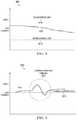
- FIGS. 4 and 5illustrate example types of diagnostics 400 and 500 that can be performed for a device using a digital output according to this disclosure.
- FIG. 4illustrates an example output over-current or under-current diagnostic 400 .
- the diagnostic 400monitors the load current 405 of the digital output. This diagnostic can generate a warning or other notification if the actual output load current 420 of a digital output module violates an undercurrent limit 410 or overcurrent limit 415 .
- This diagnostic 400can also identify whether the output current drifts over a period of time.
- FIG. 5illustrates an example output current variation diagnostic 500 .
- the diagnostic 500also monitors the load current 505 with a different focus.
- This diagnostic 500can warn of unusual changes 520 in an output current draw 515 , which could be an early warning of an output device short-circuit or open-circuit condition.
- the unusual changescan occur when the output current draw 515 is trending away from a nominal current level 510 .
- diagnosticscould be designed around specific output devices by monitoring digital output current parameters (such as DC value, rate of change, amount of on-time, or amount of off-time).
- digital output current parameterssuch as DC value, rate of change, amount of on-time, or amount of off-time.
- device-specific diagnosticscould include actuator diagnostics, solenoid diagnostics, relay diagnostics, motor starter current diagnostics, and lamp health diagnostics.
- FIG. 6illustrates an example system 600 for device diagnostics using a digital output according to this disclosure.
- a usercan be provided with the feedback digital current values. This could allow, for example, the user to develop custom diagnostics for specific field output devices 605 .
- the illustrative system 600includes a field output device 605 , a digital output module 610 , a controller 615 , a digital output channel 620 , and an output device diagnostic algorithm 625 .
- the digital output module 610connects to the field output device 605 to monitor the digital outputs.
- the digital output module 610receives output 630 from the controller 615 .
- the digital output module 610analyses the data and can provide readback 635 , live monitoring status 640 , digital current 645 , and advanced diagnostics 650 to the controller 615 .
- the digital output channel 620receives an output 655 and provides a digital current 660 to the output device diagnostic algorithm 625 .
- the output device diagnostic algorithm 625outputs advanced diagnostics 665 .
- UIO modulesupporting UNIVERSAL CHANNEL TECHNOLOGY from HONEYWELL INTERNATIONAL INC. are also suitable for use with this disclosure.
- FIGS. 2 through 6illustrate examples of digital output modules, UIO modules, diagnostics, and systems, these figures are for illustration only.
- any suitable digital output modules or UIO or reconfigurable modulescould be used to provide advanced device diagnostics.
- the specific diagnostics performedcould vary widely, such as based on the type of device coupled to a digital output module or UIO module.
- any suitable processcould be performed using diagnostics associated with a digital output module or UIO module.
- FIG. 7illustrates a process 700 for performing device diagnostics from signals on digital outputs according to this disclosure.
- the process 700 depicted in FIG. 7may be performed by the UIO module 300 .
- step 705the UIO module 300 determines whether anew digital output value is to be driven.
- step 710when the determination that a new digital output value is required, the UIO module 300 drives a new digital output value.
- step 715the UIO module 300 sample a digital output current from the ADC.
- step 720the UIO module 300 performs diagnostics on the digital output current. Example of digital output current diagnostics are provided in FIG. 8-10 . The continuous time series of the readback current enables performance of diagnostics exemplified by FIGS. 8-10 .
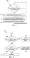
- FIGS. 8, 9 and 10illustrate example processes for performing digital output current diagnostics according to this disclosure.
- the processes depicted in FIGS. 8-10may be performed by the UIO module 300 .
- FIG. 8illustrates an example process 800 for digital current crossing an upper or lower threshold indicating a degrading load, which is illustrated in FIG. 5 .
- the UIO module 300determines whether the digital output current is above a high limit or upper threshold value.
- the UIO module 300determines whether the digital output current is below a low limit or a lower threshold value.
- the UIO module 300indicates an overcurrent error in step 810 when the digital output current is above the high limit and indicates an low current error in step 820 when the digital output current is below the low limit. If neither limit is crossed and no error is indicated, the UIO module 300 indicates that the digital output has no error in step 825 .
- FIG. 9illustrates an example process 900 for analysis of a step response to determine the impedance of the load. This test enables a determination whether the impedance of the load is changing over time and a threshold limit for failure has been reached.
- the UIO module 300determines whether a digital output state is changed. If the digital output state has not changed, the UIO module 300 determines whether a sample collection is complete in step 920 . When the digital output state has changed or the sample collection is not complete, the UIO module 300 stores the digital output current sample in step 910 and determines that test results are still pending in step 915 . When the sample collection is complete, the UIO module 300 calculates an impedance based on the step response current sample in step 925 .
- step 930the UIO module 300 determines whether the impedance is deviating from the configured threshold. When the impedance is not deviating from the configured threshold, the UIO module 300 determines that the test has been passed in step 935 . When the impedance is deviating from the configured threshold, the UIO module 300 determines that the impedance test has failed in step 940 .
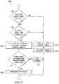
- FIG. 10illustrates an example process 1000 for checking whether there are excessively noisy conditions near the load or if the load is experiencing degradation and causing varying current to be drawn.
- the UIO module 300determines whether the digital output state is “ON.” If the digital output state is not “ON,” the test in not performed in step 1010 . When the digital output state is “ON,” the UIO module 300 stores the digital output current sample in step 1015 .
- the UIO module 300determines whether the sample collection is complete. If the sample collection is not complete, the UIO module 300 indicates that the test results are still pending in step 1025 . If the sample collection is complete, the UIO module 300 determines a variation of the current from the samples in step 1030 .
- step 1035the UIO module 300 determines whether a detected variation deviates from the configured threshold. If the variation deviates from the threshold, the UIO module 300 indicates that the variation test failed in step 1045 . If the variation does not deviate from the threshold, the UIO module 300 indicates that the variation test has passed in step 1040 .
- FIGS. 7-10illustrate examples of processes for performing device diagnostics from signals on digital outputs, respectively, various changes could be made to FIG. 7-10 .
- steps in each figurecould overlap, occur in parallel, occur in a different order, or occur multiple times.
- DOstands for “digital output”
- IOstands for “input/output”
- PLCprogrammable logic controller
- ADCstands for “analog-to-digital converter”
- V refstands for a “reference voltage used for analog-to-digital conversions.”
- a step responseis the output response of a system when a step input is applied at the input of the system.
- the impedanceis the combined effect of the resistance and reactance of a load. Sample refers to reading the instantaneous value of a physical parameter.
- various functions described in this patent documentare implemented or supported by a computer program that is formed from computer readable program code and that is embodied in a computer readable medium.
- computer readable program codeincludes any type of computer code, including source code, object code, and executable code.
- computer readable mediumincludes any type of medium capable of being accessed by a computer, such as read only memory (ROM), random access memory (RAM), a hard disk drive, a compact disc (CD), a digital video disc (DVD), or any other type of memory.
- ROMread only memory
- RAMrandom access memory
- CDcompact disc
- DVDdigital video disc
- a “non-transitory” computer readable mediumexcludes wired, wireless, optical, or other communication links that transport transitory electrical or other signals.
- a non-transitory computer readable mediumincludes media where data can be permanently stored and media where data can be stored and later overwritten, such as a rewritable optical disc or an erasable storage device.
- applicationand “program” refer to one or more computer programs, software components, sets of instructions, procedures, functions, objects, classes, instances, related data, or a portion thereof adapted for implementation in a suitable computer code (including source code, object code, or executable code).
- programrefers to one or more computer programs, software components, sets of instructions, procedures, functions, objects, classes, instances, related data, or a portion thereof adapted for implementation in a suitable computer code (including source code, object code, or executable code).
- communicateas well as derivatives thereof, encompasses both direct and indirect communication.
- the term “or”is inclusive, meaning and/or.
- phrases “associated with,” as well as derivatives thereof,may mean to include, be included within, interconnect with, contain, be contained within, connect to or with, couple to or with, be communicable with, cooperate with, interleave, juxtapose, be proximate to, be bound to or with, have, have a property of, have a relationship to or with, or the like.
- the phrase “at least one of,” when used with a list of items,means that different combinations of one or more of the listed items may be used, and only one item in the list may be needed. For example, “at least one of: A, B, and C” includes any of the following combinations: A, B, C, A and B, A and C, B and C, and A and B and C.
Landscapes
- Engineering & Computer Science (AREA)
- Physics & Mathematics (AREA)
- General Physics & Mathematics (AREA)
- Theoretical Computer Science (AREA)
- General Engineering & Computer Science (AREA)
- Business, Economics & Management (AREA)
- Emergency Management (AREA)
- Quality & Reliability (AREA)
- Computing Systems (AREA)
- Power Engineering (AREA)
- Manufacturing & Machinery (AREA)
- Mathematical Physics (AREA)
- Testing And Monitoring For Control Systems (AREA)
Abstract
Description
Claims (20)
Priority Applications (2)
| Application Number | Priority Date | Filing Date | Title |
|---|---|---|---|
| US15/615,562US10825263B2 (en) | 2016-06-16 | 2017-06-06 | Advanced discrete control device diagnostic on digital output modules |
| PCT/US2017/036960WO2017218381A1 (en) | 2016-06-16 | 2017-06-12 | Advanced discrete control device diagnostic on digital output modules |
Applications Claiming Priority (2)
| Application Number | Priority Date | Filing Date | Title |
|---|---|---|---|
| US201662350795P | 2016-06-16 | 2016-06-16 | |
| US15/615,562US10825263B2 (en) | 2016-06-16 | 2017-06-06 | Advanced discrete control device diagnostic on digital output modules |
Publications (2)
| Publication Number | Publication Date |
|---|---|
| US20170365153A1 US20170365153A1 (en) | 2017-12-21 |
| US10825263B2true US10825263B2 (en) | 2020-11-03 |
Family
ID=60659768
Family Applications (1)
| Application Number | Title | Priority Date | Filing Date |
|---|---|---|---|
| US15/615,562Active2038-02-06US10825263B2 (en) | 2016-06-16 | 2017-06-06 | Advanced discrete control device diagnostic on digital output modules |
Country Status (2)
| Country | Link |
|---|---|
| US (1) | US10825263B2 (en) |
| WO (1) | WO2017218381A1 (en) |
Families Citing this family (4)
| Publication number | Priority date | Publication date | Assignee | Title |
|---|---|---|---|---|
| TWI676087B (en)* | 2018-11-29 | 2019-11-01 | 東訊股份有限公司 | Automatic alarm system for detecting sudden deviation |
| US11151121B2 (en) | 2019-08-30 | 2021-10-19 | International Business Machines Corporation | Selective diagnostics for computing systems |
| US11449403B2 (en)* | 2019-10-09 | 2022-09-20 | Honeywell International Inc. | Apparatus and method for diagnosing faults in a fieldbus interface module |
| CN118688683B (en)* | 2024-08-28 | 2025-01-07 | 智电创能(上海)电力科技有限公司 | Automatic monitoring system and method for electrical engineering |
Citations (90)
| Publication number | Priority date | Publication date | Assignee | Title |
|---|---|---|---|---|
| US4852080A (en) | 1987-07-06 | 1989-07-25 | Oki Electric Industry Co., Ltd. | Analog front-end circuit for full-duplex communication |
| US5095417A (en) | 1988-05-17 | 1992-03-10 | Kabushiki Kaisha Komatsu Seisakusho | Apparatus for carrying out serial control |
| US5179353A (en) | 1991-01-10 | 1993-01-12 | Mitsubishi Denki Kabushiki Kaisha | Power control circuit used for both analog/digital dual mode |
| US5278508A (en)* | 1992-05-29 | 1994-01-11 | Bowman Robert M | Diagnostic apparatus displaying engine operating characteristics in the parameters in which the characteristics are measured |
| US5293122A (en) | 1992-06-08 | 1994-03-08 | Lecroy Corporation | Signal probe with remote control function |
| US5341431A (en) | 1992-10-01 | 1994-08-23 | Delco Electronics Corporation | AM stereo detection and audio processing apparatus |
| US5357517A (en) | 1989-12-26 | 1994-10-18 | Kabushiki Kaisha Komatsu Seisakusho | Error display device of data transmission system |
| US5958030A (en) | 1996-12-27 | 1999-09-28 | Nortel Networks Corporation | Intra-shelf free space interconnect |
| US6061809A (en) | 1992-03-31 | 2000-05-09 | The Dow Chemical Company | Process control interface system having triply redundant remote field units |
| US6170439B1 (en) | 1999-06-24 | 2001-01-09 | Tri-Tronics, Inc. | Remote controlled animal training system |
| US20010015924A1 (en) | 1999-12-24 | 2001-08-23 | Kazutami Arimoto | Test interface circuit and semiconductor integrated circuit device including the same |
| US6426856B1 (en)* | 1997-08-12 | 2002-07-30 | Siemens Aktiengesellschaft | Method for monitoring a protective gear |
| US20020126408A1 (en) | 2001-03-09 | 2002-09-12 | Atsushi Okuyama | Disk apparatus and information processing system |
| US20020147503A1 (en) | 2001-04-05 | 2002-10-10 | Osburn Douglas C. | Remote terminal unit |
| US20030001618A1 (en) | 2001-06-28 | 2003-01-02 | Haycock Matthew B. | Bidirectional port with clock channel used for synchronization |
| US6567653B1 (en) | 2000-04-12 | 2003-05-20 | Ericsson Inc. | Dual-mode communications transmitter |
| US20030151513A1 (en) | 2002-01-10 | 2003-08-14 | Falk Herrmann | Self-organizing hierarchical wireless network for surveillance and control |
| US6639806B1 (en) | 1999-12-23 | 2003-10-28 | Asustek Computer Inc. | Motherboard and expansion board for providing such motherboard with slots |
| US6654351B1 (en) | 2000-03-08 | 2003-11-25 | Motorola Inc. | Configurable multi-protocol vehicle communication circuit and method |
| US20040199674A1 (en) | 2003-02-24 | 2004-10-07 | Brinkhus Hartmut B. | Interface circuit for process connections |
| US20040259533A1 (en) | 2003-06-18 | 2004-12-23 | Mark Nixon | Self-configuring communication networks for use with process control systems |
| US6862636B2 (en) | 2001-11-16 | 2005-03-01 | Gateway, Inc. | Multi-mode speaker operating from either digital or analog sources |
| US20050058453A1 (en) | 2003-09-12 | 2005-03-17 | Willem Mostert | Optical network architecture for simultaneous transport of analog video signals and ethernet data |
| US20050070177A1 (en) | 2003-07-21 | 2005-03-31 | Siemens Building Technologies Ag | Arrangement for the operation of field devices of an administration and maintenance unit of a building |
| US20050174964A1 (en) | 2004-02-06 | 2005-08-11 | Philip Orlik | Coordinating communications in a heterogeneous communications network using different signal formats |
| WO2005086110A2 (en) | 2004-03-02 | 2005-09-15 | Rosemount, Inc. | Field-mounted process device with programmable digital/analog interface |
| US20050216107A1 (en) | 1997-10-13 | 2005-09-29 | Viserge Limited. | Remote terminal unit assembly |
| US20050243867A1 (en) | 1998-06-22 | 2005-11-03 | Statsignal Ipc, Llc | Systems and methods for monitoring and controlling remote devices |
| US20050273205A1 (en) | 2002-10-15 | 2005-12-08 | Rain Bird Corporation | Modular and expandable irrigation controller |
| US6981090B1 (en) | 2000-10-26 | 2005-12-27 | Cypress Semiconductor Corporation | Multiple use of microcontroller pad |
| US20060087402A1 (en) | 2004-10-22 | 2006-04-27 | Manning Anthony J | Quality control system and method for construction, commissioning, and other initiation of a process plant |
| US20060170403A1 (en) | 2005-01-28 | 2006-08-03 | Joon-Hyuk Im | Voltage regulator with reduced power consumption in standby operating mode |
| US20060202728A1 (en) | 2004-04-26 | 2006-09-14 | Atmel Corporation | Charge pump clock for non-volatile memories |
| US20060240818A1 (en) | 2005-04-22 | 2006-10-26 | Mccoy Robert | System, method, and apparatus for command and control of remote instrumentation |
| US7165139B2 (en) | 2001-09-14 | 2007-01-16 | Cornice, Inc. | Digital device configuration and method |
| US7227349B2 (en) | 2002-02-11 | 2007-06-05 | Tektronix, Inc. | Method and apparatus for the digital and analog triggering of a signal analysis device |
| US20070213652A1 (en) | 2005-12-30 | 2007-09-13 | Transcutaneous Technologies Inc. | System and method for remote based control of an iontophoresis device |
| US20070223382A1 (en) | 2006-03-24 | 2007-09-27 | Rockwell Automation Technologies, Inc. | Programmable routing module |
| US20070280144A1 (en) | 2006-05-31 | 2007-12-06 | Honeywell International Inc. | Apparatus and method for integrating wireless field devices with a wired protocol in a process control system |
| US20080077336A1 (en) | 2006-09-25 | 2008-03-27 | Roosevelt Fernandes | Power line universal monitor |
| US20080080395A1 (en) | 2006-09-29 | 2008-04-03 | Gary Keith Law | Flexible input/output devices for use in process control systems |
| US7480126B2 (en) | 2005-04-27 | 2009-01-20 | National Instruments Corporation | Protection and voltage monitoring circuit |
| US20090201150A1 (en) | 2008-02-08 | 2009-08-13 | Honeywell International Inc. | Apparatus and method for providing a failsafe-enabled wireless device |
| US20090224906A1 (en) | 2008-02-26 | 2009-09-10 | Abb Research Ltd. | Method for configuring a node of an industrial wireless network |
| US20090271558A1 (en) | 2008-04-24 | 2009-10-29 | Honeywell International, Inc. | Programmable channel |
| US20090316628A1 (en) | 2008-06-18 | 2009-12-24 | Frederick Enns | System and method for wireless process communication over distinct networks |
| US20100079007A1 (en) | 2008-09-29 | 2010-04-01 | Honeywell International Inc. | Remotely configurable analog/digital input circuit and related apparatus and method |
| US20100123483A1 (en) | 2008-11-17 | 2010-05-20 | Shine Chung | Circuit and Method for a Digital Process Monitor |
| KR20100066815A (en) | 2008-12-10 | 2010-06-18 | 현대중공업 주식회사 | Automated test device for remote terminal unit |
| US20100176933A1 (en) | 2009-01-14 | 2010-07-15 | Eon Corporation | Remotely monitoring field assets |
| US20100264946A1 (en)* | 2009-04-20 | 2010-10-21 | Tektronix, Inc. | Test and measurement instrument and method of configuring using a sensed impedance |
| US20110110291A1 (en) | 2009-11-10 | 2011-05-12 | Yokogawa Electric Corporation | Relay device and wireless control network management system using the same |
| US7969300B2 (en) | 2004-08-30 | 2011-06-28 | International Business Machines Corporation | Signal transmission between a sensor and a controller device in a wireless sensor network |
| US20110246791A1 (en) | 2010-03-31 | 2011-10-06 | Kabushiki Kaisha Toshiba | Memory chip, information storing system, and reading device |
| US20110276607A1 (en) | 2010-05-05 | 2011-11-10 | Microsoft Corporation | Normalizing data for fast superscalar processing |
| US20120041574A1 (en) | 2000-03-10 | 2012-02-16 | Smiths Detection, Inc. | Temporary expanding integrated monitoring network |
| US8135884B1 (en) | 2009-05-04 | 2012-03-13 | Cypress Semiconductor Corporation | Programmable interrupt routing system |
| US20120063330A1 (en) | 2010-09-03 | 2012-03-15 | Yokogawa Electric Corporation | Wireless network path setting apparatus and method |
| US20120078869A1 (en) | 2010-09-23 | 2012-03-29 | Keith Richard Bellville | Methods and apparatus to manage process control search results |
| US20120084400A1 (en) | 2010-07-23 | 2012-04-05 | Almadi Soloman M | Machines, Computer Program Products, and Computer-Implemented Methods Providing an Integrated Node for Data Acquisition and Control |
| US20120151588A1 (en) | 2010-12-09 | 2012-06-14 | At&T Intellectual Property I, L.P. | Malware Detection for SMS/MMS Based Attacks |
| US8239046B2 (en) | 2007-02-26 | 2012-08-07 | International Business Machines Corporation | Sensor network controllers |
| US20120230446A1 (en) | 2011-03-11 | 2012-09-13 | Xiang Feng | Method and Apparatus for Incorporating a WirelessHART-Enabled Device into a Wired HART Network |
| US20120236768A1 (en) | 2011-03-18 | 2012-09-20 | Honeywell International Inc. | Adapter device for coupling an industrial field instrument to an industrial wireless network and related system and method |
| US20120290735A1 (en) | 2006-08-25 | 2012-11-15 | Invensys Systems, Inc. | Remote operation of process control equipment over customer supplied network |
| US20120293017A1 (en)* | 2011-04-25 | 2012-11-22 | Volterra Semiconductor Corporation | Integrated protection devices with monitoring of electrical characteristics |
| KR20120135142A (en) | 2012-07-26 | 2012-12-12 | 전성득 | Remote transfer unit apparatus with communication unit |
| US20130110998A1 (en) | 2011-10-28 | 2013-05-02 | Yokogawa Electric Corporation | Network management interface for heterogeneous data network and system using the same |
| US20130151849A1 (en) | 2009-03-18 | 2013-06-13 | University Of Louisville Research Foundation, Inc. | Device, method, and system for processing communications for secure operation of industrial control system field devices |
| US20130173840A1 (en) | 2011-12-30 | 2013-07-04 | Maxim Integrated Products, Inc. | Communications control system with a serial communications interface and a parallel communications interface |
| US20130246801A1 (en) | 2012-03-13 | 2013-09-19 | Toshinari Takahashi | Data transmitting device, data receiving device, and computer-readable storage medium |
| US20130262064A1 (en) | 2012-03-27 | 2013-10-03 | General Electric Company | Systems and methods for improved reliability operations |
| US8583067B2 (en) | 2008-09-24 | 2013-11-12 | Honeywell International Inc. | Apparatus and method for improved wireless communication reliability and performance in process control systems |
| US20130307699A1 (en) | 2010-09-29 | 2013-11-21 | Endre Brekke | Arrangement and Method for Controlling and/or Monitoring a Subsea Device |
| US20130344839A1 (en) | 2012-06-22 | 2013-12-26 | Sean Roach | Comfort device, system and method with electronic message display |
| US8656065B1 (en) | 2013-01-29 | 2014-02-18 | Honeywell International Inc. | Method and apparatus for automatically selecting a plurality of modes for programmable interface circuit by coupling field devices to process controllers |
| US20140092503A1 (en) | 2012-10-01 | 2014-04-03 | Leviton Manufacturing Company, Inc | Processor-based circuit interrupting devices |
| US20140119290A1 (en) | 2012-11-01 | 2014-05-01 | General Electric Company | Systems and methods of bandwidth allocation |
| US20140232555A1 (en) | 2011-06-24 | 2014-08-21 | Gassecure As | Wireless sensor networks |
| US20140321443A1 (en) | 2013-04-26 | 2014-10-30 | Honeywell International, Inc. | Slot segregation for supporting multiple communication protocols in an industrial wireless network |
| WO2014197182A1 (en) | 2013-06-03 | 2014-12-11 | Honeywell International Inc. | Apparatus and method for providing a common interface for multiple wireless communication protocols |
| US20150058480A1 (en) | 2013-08-20 | 2015-02-26 | Vega Grieshaber Kg | Measuring Instrument Access Apparatus, Field Device, and Method for Controlling the Access to a Measuring Instrument |
| WO2015047744A1 (en) | 2013-09-24 | 2015-04-02 | Honeywell International Inc. | Remote terminal unit (rtu) with wireless diversity and related method |
| US9021255B1 (en) | 2012-06-29 | 2015-04-28 | Emc Corporation | Techniques for multiple independent verifications for digital certificates |
| US20150270014A1 (en) | 2014-03-19 | 2015-09-24 | Sandisk Enterprise Ip Llc | Fault Detection and Prediction for Data Storage Elements |
| US20150278144A1 (en) | 2014-03-27 | 2015-10-01 | Honeywell International Inc. | Remote terminal unit (rtu) with universary input/output (uio) and related method |
| US20150304193A1 (en) | 2012-04-18 | 2015-10-22 | Yokogawa Electric Corporation | Controller, control system, and control method |
| US20150355242A1 (en) | 2014-06-06 | 2015-12-10 | Dialog Semiconductor Gmbh | Output Current Monitoring Circuit |
| US20160048474A1 (en) | 2014-08-14 | 2016-02-18 | Honeywell International Inc. | Remote terminal unit (rtu) hardware architecture |
| US9908418B2 (en)* | 2013-06-20 | 2018-03-06 | Bayerische Motoren Werke Aktiengesellschaft | Circuit arrangement and energy storage system |
- 2017
- 2017-06-06USUS15/615,562patent/US10825263B2/enactiveActive
- 2017-06-12WOPCT/US2017/036960patent/WO2017218381A1/ennot_activeCeased
Patent Citations (101)
| Publication number | Priority date | Publication date | Assignee | Title |
|---|---|---|---|---|
| US4852080A (en) | 1987-07-06 | 1989-07-25 | Oki Electric Industry Co., Ltd. | Analog front-end circuit for full-duplex communication |
| US5095417A (en) | 1988-05-17 | 1992-03-10 | Kabushiki Kaisha Komatsu Seisakusho | Apparatus for carrying out serial control |
| US5357517A (en) | 1989-12-26 | 1994-10-18 | Kabushiki Kaisha Komatsu Seisakusho | Error display device of data transmission system |
| US5179353A (en) | 1991-01-10 | 1993-01-12 | Mitsubishi Denki Kabushiki Kaisha | Power control circuit used for both analog/digital dual mode |
| US6061809A (en) | 1992-03-31 | 2000-05-09 | The Dow Chemical Company | Process control interface system having triply redundant remote field units |
| US5278508A (en)* | 1992-05-29 | 1994-01-11 | Bowman Robert M | Diagnostic apparatus displaying engine operating characteristics in the parameters in which the characteristics are measured |
| US5293122A (en) | 1992-06-08 | 1994-03-08 | Lecroy Corporation | Signal probe with remote control function |
| US5341431A (en) | 1992-10-01 | 1994-08-23 | Delco Electronics Corporation | AM stereo detection and audio processing apparatus |
| US5958030A (en) | 1996-12-27 | 1999-09-28 | Nortel Networks Corporation | Intra-shelf free space interconnect |
| US6426856B1 (en)* | 1997-08-12 | 2002-07-30 | Siemens Aktiengesellschaft | Method for monitoring a protective gear |
| US20050216107A1 (en) | 1997-10-13 | 2005-09-29 | Viserge Limited. | Remote terminal unit assembly |
| US20050243867A1 (en) | 1998-06-22 | 2005-11-03 | Statsignal Ipc, Llc | Systems and methods for monitoring and controlling remote devices |
| US6170439B1 (en) | 1999-06-24 | 2001-01-09 | Tri-Tronics, Inc. | Remote controlled animal training system |
| US6639806B1 (en) | 1999-12-23 | 2003-10-28 | Asustek Computer Inc. | Motherboard and expansion board for providing such motherboard with slots |
| US20010015924A1 (en) | 1999-12-24 | 2001-08-23 | Kazutami Arimoto | Test interface circuit and semiconductor integrated circuit device including the same |
| US6654351B1 (en) | 2000-03-08 | 2003-11-25 | Motorola Inc. | Configurable multi-protocol vehicle communication circuit and method |
| US8352049B2 (en) | 2000-03-10 | 2013-01-08 | Smiths Detection Inc. | Temporary expanding integrated monitoring network |
| US20120041574A1 (en) | 2000-03-10 | 2012-02-16 | Smiths Detection, Inc. | Temporary expanding integrated monitoring network |
| US6567653B1 (en) | 2000-04-12 | 2003-05-20 | Ericsson Inc. | Dual-mode communications transmitter |
| US6981090B1 (en) | 2000-10-26 | 2005-12-27 | Cypress Semiconductor Corporation | Multiple use of microcontroller pad |
| US20020126408A1 (en) | 2001-03-09 | 2002-09-12 | Atsushi Okuyama | Disk apparatus and information processing system |
| US20020147503A1 (en) | 2001-04-05 | 2002-10-10 | Osburn Douglas C. | Remote terminal unit |
| US20030001618A1 (en) | 2001-06-28 | 2003-01-02 | Haycock Matthew B. | Bidirectional port with clock channel used for synchronization |
| US7165139B2 (en) | 2001-09-14 | 2007-01-16 | Cornice, Inc. | Digital device configuration and method |
| US6862636B2 (en) | 2001-11-16 | 2005-03-01 | Gateway, Inc. | Multi-mode speaker operating from either digital or analog sources |
| US20030151513A1 (en) | 2002-01-10 | 2003-08-14 | Falk Herrmann | Self-organizing hierarchical wireless network for surveillance and control |
| US7227349B2 (en) | 2002-02-11 | 2007-06-05 | Tektronix, Inc. | Method and apparatus for the digital and analog triggering of a signal analysis device |
| US20050273205A1 (en) | 2002-10-15 | 2005-12-08 | Rain Bird Corporation | Modular and expandable irrigation controller |
| US20040199674A1 (en) | 2003-02-24 | 2004-10-07 | Brinkhus Hartmut B. | Interface circuit for process connections |
| US20040259533A1 (en) | 2003-06-18 | 2004-12-23 | Mark Nixon | Self-configuring communication networks for use with process control systems |
| US20050070177A1 (en) | 2003-07-21 | 2005-03-31 | Siemens Building Technologies Ag | Arrangement for the operation of field devices of an administration and maintenance unit of a building |
| US20050058453A1 (en) | 2003-09-12 | 2005-03-17 | Willem Mostert | Optical network architecture for simultaneous transport of analog video signals and ethernet data |
| US20050174964A1 (en) | 2004-02-06 | 2005-08-11 | Philip Orlik | Coordinating communications in a heterogeneous communications network using different signal formats |
| US7555004B2 (en) | 2004-02-06 | 2009-06-30 | Mitsubishi Electric Research Laboratories, Inc. | Coordinating communications in a heterogeneous communications network using different signal formats |
| WO2005086110A2 (en) | 2004-03-02 | 2005-09-15 | Rosemount, Inc. | Field-mounted process device with programmable digital/analog interface |
| JP4990755B2 (en) | 2004-03-02 | 2012-08-01 | ローズマウント インコーポレイテッド | Field-mounted process equipment with programmable digital / analog interface |
| JP2007527073A (en) | 2004-03-02 | 2007-09-20 | ローズマウント インコーポレイテッド | Field-mounted process equipment with programmable digital / analog interface |
| US20060202728A1 (en) | 2004-04-26 | 2006-09-14 | Atmel Corporation | Charge pump clock for non-volatile memories |
| US7969300B2 (en) | 2004-08-30 | 2011-06-28 | International Business Machines Corporation | Signal transmission between a sensor and a controller device in a wireless sensor network |
| US20060087402A1 (en) | 2004-10-22 | 2006-04-27 | Manning Anthony J | Quality control system and method for construction, commissioning, and other initiation of a process plant |
| US20060170403A1 (en) | 2005-01-28 | 2006-08-03 | Joon-Hyuk Im | Voltage regulator with reduced power consumption in standby operating mode |
| US20060240818A1 (en) | 2005-04-22 | 2006-10-26 | Mccoy Robert | System, method, and apparatus for command and control of remote instrumentation |
| US7480126B2 (en) | 2005-04-27 | 2009-01-20 | National Instruments Corporation | Protection and voltage monitoring circuit |
| US20070213652A1 (en) | 2005-12-30 | 2007-09-13 | Transcutaneous Technologies Inc. | System and method for remote based control of an iontophoresis device |
| US20070223382A1 (en) | 2006-03-24 | 2007-09-27 | Rockwell Automation Technologies, Inc. | Programmable routing module |
| US20070280144A1 (en) | 2006-05-31 | 2007-12-06 | Honeywell International Inc. | Apparatus and method for integrating wireless field devices with a wired protocol in a process control system |
| US20120290735A1 (en) | 2006-08-25 | 2012-11-15 | Invensys Systems, Inc. | Remote operation of process control equipment over customer supplied network |
| US20080077336A1 (en) | 2006-09-25 | 2008-03-27 | Roosevelt Fernandes | Power line universal monitor |
| US20080080395A1 (en) | 2006-09-29 | 2008-04-03 | Gary Keith Law | Flexible input/output devices for use in process control systems |
| US8239046B2 (en) | 2007-02-26 | 2012-08-07 | International Business Machines Corporation | Sensor network controllers |
| US20090201150A1 (en) | 2008-02-08 | 2009-08-13 | Honeywell International Inc. | Apparatus and method for providing a failsafe-enabled wireless device |
| US20090224906A1 (en) | 2008-02-26 | 2009-09-10 | Abb Research Ltd. | Method for configuring a node of an industrial wireless network |
| US8392626B2 (en) | 2008-04-24 | 2013-03-05 | Honeywell International Inc. | Programmable channel circuit for coupling signals between field devices and control systems |
| US20090271558A1 (en) | 2008-04-24 | 2009-10-29 | Honeywell International, Inc. | Programmable channel |
| US9379972B2 (en) | 2008-06-18 | 2016-06-28 | Fisher-Rosemount Systems, Inc. | System and method for wireless process communication over distinct networks |
| US20090316628A1 (en) | 2008-06-18 | 2009-12-24 | Frederick Enns | System and method for wireless process communication over distinct networks |
| US8315263B2 (en) | 2008-06-18 | 2012-11-20 | Fisher-Rosemount Systems, Inc. | System and method for wireless process communication over distinct networks |
| US8583067B2 (en) | 2008-09-24 | 2013-11-12 | Honeywell International Inc. | Apparatus and method for improved wireless communication reliability and performance in process control systems |
| US8072098B2 (en)* | 2008-09-29 | 2011-12-06 | Honeywell International Inc. | Remotely configurable analog/digital input circuit and related apparatus and method |
| US20100079007A1 (en) | 2008-09-29 | 2010-04-01 | Honeywell International Inc. | Remotely configurable analog/digital input circuit and related apparatus and method |
| US20100123483A1 (en) | 2008-11-17 | 2010-05-20 | Shine Chung | Circuit and Method for a Digital Process Monitor |
| KR20100066815A (en) | 2008-12-10 | 2010-06-18 | 현대중공업 주식회사 | Automated test device for remote terminal unit |
| US20100176933A1 (en) | 2009-01-14 | 2010-07-15 | Eon Corporation | Remotely monitoring field assets |
| US8868907B2 (en) | 2009-03-18 | 2014-10-21 | University Of Louisville Research Foundation, Inc. | Device, method, and system for processing communications for secure operation of industrial control system field devices |
| US20130151849A1 (en) | 2009-03-18 | 2013-06-13 | University Of Louisville Research Foundation, Inc. | Device, method, and system for processing communications for secure operation of industrial control system field devices |
| US20100264946A1 (en)* | 2009-04-20 | 2010-10-21 | Tektronix, Inc. | Test and measurement instrument and method of configuring using a sensed impedance |
| US8135884B1 (en) | 2009-05-04 | 2012-03-13 | Cypress Semiconductor Corporation | Programmable interrupt routing system |
| US20110110291A1 (en) | 2009-11-10 | 2011-05-12 | Yokogawa Electric Corporation | Relay device and wireless control network management system using the same |
| US20110246791A1 (en) | 2010-03-31 | 2011-10-06 | Kabushiki Kaisha Toshiba | Memory chip, information storing system, and reading device |
| US20110276607A1 (en) | 2010-05-05 | 2011-11-10 | Microsoft Corporation | Normalizing data for fast superscalar processing |
| JP2013535730A (en) | 2010-07-23 | 2013-09-12 | サウジ アラビアン オイル カンパニー | Machine, computer program product, and computer-implemented method for providing an integrated node for data collection and control |
| US8667091B2 (en) | 2010-07-23 | 2014-03-04 | Saudi Arabian Oil Company | Machines, computer program products, and computer-implemented methods providing an integrated node for data acquisition and control |
| US20120084400A1 (en) | 2010-07-23 | 2012-04-05 | Almadi Soloman M | Machines, Computer Program Products, and Computer-Implemented Methods Providing an Integrated Node for Data Acquisition and Control |
| US20120063330A1 (en) | 2010-09-03 | 2012-03-15 | Yokogawa Electric Corporation | Wireless network path setting apparatus and method |
| US20120078869A1 (en) | 2010-09-23 | 2012-03-29 | Keith Richard Bellville | Methods and apparatus to manage process control search results |
| US20130307699A1 (en) | 2010-09-29 | 2013-11-21 | Endre Brekke | Arrangement and Method for Controlling and/or Monitoring a Subsea Device |
| US20120151588A1 (en) | 2010-12-09 | 2012-06-14 | At&T Intellectual Property I, L.P. | Malware Detection for SMS/MMS Based Attacks |
| US20120230446A1 (en) | 2011-03-11 | 2012-09-13 | Xiang Feng | Method and Apparatus for Incorporating a WirelessHART-Enabled Device into a Wired HART Network |
| US20120236768A1 (en) | 2011-03-18 | 2012-09-20 | Honeywell International Inc. | Adapter device for coupling an industrial field instrument to an industrial wireless network and related system and method |
| US20120293017A1 (en)* | 2011-04-25 | 2012-11-22 | Volterra Semiconductor Corporation | Integrated protection devices with monitoring of electrical characteristics |
| US20140232555A1 (en) | 2011-06-24 | 2014-08-21 | Gassecure As | Wireless sensor networks |
| US20130110998A1 (en) | 2011-10-28 | 2013-05-02 | Yokogawa Electric Corporation | Network management interface for heterogeneous data network and system using the same |
| US20130173840A1 (en) | 2011-12-30 | 2013-07-04 | Maxim Integrated Products, Inc. | Communications control system with a serial communications interface and a parallel communications interface |
| US20130246801A1 (en) | 2012-03-13 | 2013-09-19 | Toshinari Takahashi | Data transmitting device, data receiving device, and computer-readable storage medium |
| US20130262064A1 (en) | 2012-03-27 | 2013-10-03 | General Electric Company | Systems and methods for improved reliability operations |
| US20150304193A1 (en) | 2012-04-18 | 2015-10-22 | Yokogawa Electric Corporation | Controller, control system, and control method |
| US20130344839A1 (en) | 2012-06-22 | 2013-12-26 | Sean Roach | Comfort device, system and method with electronic message display |
| US9021255B1 (en) | 2012-06-29 | 2015-04-28 | Emc Corporation | Techniques for multiple independent verifications for digital certificates |
| KR20120135142A (en) | 2012-07-26 | 2012-12-12 | 전성득 | Remote transfer unit apparatus with communication unit |
| US20140092503A1 (en) | 2012-10-01 | 2014-04-03 | Leviton Manufacturing Company, Inc | Processor-based circuit interrupting devices |
| US20140119290A1 (en) | 2012-11-01 | 2014-05-01 | General Electric Company | Systems and methods of bandwidth allocation |
| US8656065B1 (en) | 2013-01-29 | 2014-02-18 | Honeywell International Inc. | Method and apparatus for automatically selecting a plurality of modes for programmable interface circuit by coupling field devices to process controllers |
| US20140321443A1 (en) | 2013-04-26 | 2014-10-30 | Honeywell International, Inc. | Slot segregation for supporting multiple communication protocols in an industrial wireless network |
| WO2014197182A1 (en) | 2013-06-03 | 2014-12-11 | Honeywell International Inc. | Apparatus and method for providing a common interface for multiple wireless communication protocols |
| US9908418B2 (en)* | 2013-06-20 | 2018-03-06 | Bayerische Motoren Werke Aktiengesellschaft | Circuit arrangement and energy storage system |
| US20150058480A1 (en) | 2013-08-20 | 2015-02-26 | Vega Grieshaber Kg | Measuring Instrument Access Apparatus, Field Device, and Method for Controlling the Access to a Measuring Instrument |
| WO2015047744A1 (en) | 2013-09-24 | 2015-04-02 | Honeywell International Inc. | Remote terminal unit (rtu) with wireless diversity and related method |
| US20150270014A1 (en) | 2014-03-19 | 2015-09-24 | Sandisk Enterprise Ip Llc | Fault Detection and Prediction for Data Storage Elements |
| US20150278144A1 (en) | 2014-03-27 | 2015-10-01 | Honeywell International Inc. | Remote terminal unit (rtu) with universary input/output (uio) and related method |
| US20150355242A1 (en) | 2014-06-06 | 2015-12-10 | Dialog Semiconductor Gmbh | Output Current Monitoring Circuit |
| US20160048474A1 (en) | 2014-08-14 | 2016-02-18 | Honeywell International Inc. | Remote terminal unit (rtu) hardware architecture |
Non-Patent Citations (17)
| Title |
|---|
| "25A Right Angle Signal/Power Combo", SAMTEC Power Strip 25, 2008, 1 page. |
| "ControlWave Micro Process Automation Controller", Instruction Manual, Emerson Process Management, Jun. 2013, 170 pages. |
| "FCN-RTU Low Power Autonomous Controller Hardware", STARDOM FCN-RTU, Yokogawa Electric Corporation, Dec. 2008, 13 pages. |
| David D. Brandt, "Solving the Issue of Interoperability among Devices and Systems", May 19, 2008, p. 1-21, XP055091082. |
| European Search Report dated Sep. 22, 2014, in connection with European Patent Application No. 14164273.6; 3 pages. |
| International Search Report and Written Opinion dated Oct. 27, 2015, in connection with PCT/US2015/043607; 12 pages. |
| International Search Report and Written Opinion of the International Searching Authority for International Application No. PCT/US2017/036960 dated Sep. 21, 2017, 10 pages. |
| International Search Report dated Dec. 11, 2014, in connection with International Application No. PCT/US2014/055307; 4 pages. |
| International Search Report dated Oct. 10, 2014, in connection with International Application No. PCT/US2014/038208; 3 pages. |
| Notification of Transmittal of the International Search Report and the Written Opinion of the International Searching Authority, or the Declaration dated Jun. 10, 2015, in connection with International Patent Application No. PCT/US2015/019671; 12 pages. |
| Rockwell Automation; "FLEX I/O Digital input and Output Modules w/Diagnostics—Installation Instructions"; Allen-Bradley; Publication 1794-IN096C-EN-P; Aug. 2015; 22 pages. |
| Siemens; "New SM322-813H01 Digital Output Module with Diagnostics"; Industry Online Support; Siemens AG; https://support.industry.siemens.com/cs/document/17968869/new-sm322-8bh01-digital-output-module-with-diagnostics?dti=0&lc=en-CN; 2 pages. |
| Siemens; "SIMATIC—ET 200M Signal Modules for Process Automation—Configuration Manual—Oct. 2014 Edition"; ASE00085262-04; 74 pages. |
| Supplementary European Search Report dated Apr. 28, 2017, in connection with European Patent Application No. EP 14 84 8127; 9 pages. |
| U.S. Patent Application "Remote Terminal Unit (RTU) With Wireless Diversity and Related Method" U.S. Appl. No. 14/035,557, filed Sep. 24, 2013. 33 pages. |
| Written Opinion of the International Searching Authority dated Dec. 11, 2014, in connection with International Application No. PCT/US2014/055307; 7 pages. |
| Written Opinion of the International Searching Authority dated Oct. 10, 2014, in connection with International Application No. PCT/US2014/038208; 5 pages. |
Also Published As
| Publication number | Publication date |
|---|---|
| US20170365153A1 (en) | 2017-12-21 |
| WO2017218381A1 (en) | 2017-12-21 |
Similar Documents
| Publication | Publication Date | Title |
|---|---|---|
| US10825263B2 (en) | Advanced discrete control device diagnostic on digital output modules | |
| US10614214B2 (en) | Using machine learning to detect communication channel abnormalities in an ICS/IIoT application | |
| US9507336B2 (en) | Apparatus and method for determining an aggregate control connection status of a field device in a process control system | |
| US10139788B2 (en) | Remote data analytics to predict system components or device failure | |
| EP3721600A1 (en) | Using machine learning in an industrial control network to improve cybersecurity operations | |
| US10135470B2 (en) | System and method to auto-configure a transmitter for a sensor | |
| US10699556B1 (en) | System and method for plant operation gap analysis and guidance solution | |
| CN107850639B (en) | System and method for dynamic ground fault detection | |
| CN110892348B (en) | Traditional control function and NEWGEN control function in NEWGEN controller | |
| US20180372788A1 (en) | Universal terminals transmitter supporting flexible connection of rtd sensor | |
| US20170082469A1 (en) | Inline ultrasonic meter (usm) condition based monitoring (cbm)-based adaptation to maintain high accuracy under various flow conditions | |
| EP3137957B1 (en) | Apparatus and method for providing a generalized continuous performance indicator | |
| CA3073435C (en) | Detection of loop resistance and leakage current in input/output (i/o) loop | |
| US9779610B2 (en) | Automated loop check for smart junction boxes | |
| EP3420617B1 (en) | System and method for multi-level electronic protection using combination of current sensing and temperature sensing | |
| US11451632B2 (en) | System and method for supporting wired and wireless communications in industrial safety systems | |
| US11997009B2 (en) | Method and apparatus for an alternate communication path for connected networks | |
| US20170277142A1 (en) | Process control system performance analysis using scenario data | |
| EP4148521B1 (en) | Autonomous instrument management | |
| US11449403B2 (en) | Apparatus and method for diagnosing faults in a fieldbus interface module | |
| KR20190091700A (en) | Predictive maintenance method and system of facilities by studying type of electricity consumption data using facilities control characteristic |
Legal Events
| Date | Code | Title | Description |
|---|---|---|---|
| AS | Assignment | Owner name:HONEYWELL INTERNATIONAL INC., NEW JERSEY Free format text:ASSIGNMENT OF ASSIGNORS INTEREST;ASSIGNORS:SUNDARESH, NAGARAJA;PENDYALA, SHANKAR RAO;CARNEY, MICHAEL D.;AND OTHERS;SIGNING DATES FROM 20170605 TO 20170606;REEL/FRAME:042619/0718 | |
| STPP | Information on status: patent application and granting procedure in general | Free format text:RESPONSE TO NON-FINAL OFFICE ACTION ENTERED AND FORWARDED TO EXAMINER | |
| STPP | Information on status: patent application and granting procedure in general | Free format text:NON FINAL ACTION MAILED | |
| STPP | Information on status: patent application and granting procedure in general | Free format text:NON FINAL ACTION MAILED | |
| STPP | Information on status: patent application and granting procedure in general | Free format text:RESPONSE TO NON-FINAL OFFICE ACTION ENTERED AND FORWARDED TO EXAMINER | |
| STPP | Information on status: patent application and granting procedure in general | Free format text:NOTICE OF ALLOWANCE MAILED -- APPLICATION RECEIVED IN OFFICE OF PUBLICATIONS | |
| STCF | Information on status: patent grant | Free format text:PATENTED CASE | |
| MAFP | Maintenance fee payment | Free format text:PAYMENT OF MAINTENANCE FEE, 4TH YEAR, LARGE ENTITY (ORIGINAL EVENT CODE: M1551); ENTITY STATUS OF PATENT OWNER: LARGE ENTITY Year of fee payment:4 |