US10824526B2 - Using failed storage device in peer-to-peer storage system to perform storage-centric task - Google Patents
Using failed storage device in peer-to-peer storage system to perform storage-centric taskDownload PDFInfo
- Publication number
- US10824526B2 US10824526B2US16/054,892US201816054892AUS10824526B2US 10824526 B2US10824526 B2US 10824526B2US 201816054892 AUS201816054892 AUS 201816054892AUS 10824526 B2US10824526 B2US 10824526B2
- Authority
- US
- United States
- Prior art keywords
- storage
- storage device
- failed
- functioning
- task
- Prior art date
- Legal status (The legal status is an assumption and is not a legal conclusion. Google has not performed a legal analysis and makes no representation as to the accuracy of the status listed.)
- Active, expires
Links
Images


Classifications
- G—PHYSICS
- G06—COMPUTING OR CALCULATING; COUNTING
- G06F—ELECTRIC DIGITAL DATA PROCESSING
- G06F3/00—Input arrangements for transferring data to be processed into a form capable of being handled by the computer; Output arrangements for transferring data from processing unit to output unit, e.g. interface arrangements
- G06F3/06—Digital input from, or digital output to, record carriers, e.g. RAID, emulated record carriers or networked record carriers
- G06F3/0601—Interfaces specially adapted for storage systems
- G06F3/0668—Interfaces specially adapted for storage systems adopting a particular infrastructure
- G06F3/067—Distributed or networked storage systems, e.g. storage area networks [SAN], network attached storage [NAS]
- G—PHYSICS
- G06—COMPUTING OR CALCULATING; COUNTING
- G06F—ELECTRIC DIGITAL DATA PROCESSING
- G06F11/00—Error detection; Error correction; Monitoring
- G06F11/07—Responding to the occurrence of a fault, e.g. fault tolerance
- G06F11/16—Error detection or correction of the data by redundancy in hardware
- G06F11/20—Error detection or correction of the data by redundancy in hardware using active fault-masking, e.g. by switching out faulty elements or by switching in spare elements
- G06F11/2053—Error detection or correction of the data by redundancy in hardware using active fault-masking, e.g. by switching out faulty elements or by switching in spare elements where persistent mass storage functionality or persistent mass storage control functionality is redundant
- G06F11/2094—Redundant storage or storage space
- G—PHYSICS
- G06—COMPUTING OR CALCULATING; COUNTING
- G06F—ELECTRIC DIGITAL DATA PROCESSING
- G06F11/00—Error detection; Error correction; Monitoring
- G06F11/07—Responding to the occurrence of a fault, e.g. fault tolerance
- G06F11/0703—Error or fault processing not based on redundancy, i.e. by taking additional measures to deal with the error or fault not making use of redundancy in operation, in hardware, or in data representation
- G06F11/0706—Error or fault processing not based on redundancy, i.e. by taking additional measures to deal with the error or fault not making use of redundancy in operation, in hardware, or in data representation the processing taking place on a specific hardware platform or in a specific software environment
- G06F11/0727—Error or fault processing not based on redundancy, i.e. by taking additional measures to deal with the error or fault not making use of redundancy in operation, in hardware, or in data representation the processing taking place on a specific hardware platform or in a specific software environment in a storage system, e.g. in a DASD or network based storage system
- G—PHYSICS
- G06—COMPUTING OR CALCULATING; COUNTING
- G06F—ELECTRIC DIGITAL DATA PROCESSING
- G06F11/00—Error detection; Error correction; Monitoring
- G06F11/07—Responding to the occurrence of a fault, e.g. fault tolerance
- G06F11/14—Error detection or correction of the data by redundancy in operation
- G06F11/1402—Saving, restoring, recovering or retrying
- G06F11/1446—Point-in-time backing up or restoration of persistent data
- G06F11/1458—Management of the backup or restore process
- G06F11/1464—Management of the backup or restore process for networked environments
- G—PHYSICS
- G06—COMPUTING OR CALCULATING; COUNTING
- G06F—ELECTRIC DIGITAL DATA PROCESSING
- G06F3/00—Input arrangements for transferring data to be processed into a form capable of being handled by the computer; Output arrangements for transferring data from processing unit to output unit, e.g. interface arrangements
- G06F3/06—Digital input from, or digital output to, record carriers, e.g. RAID, emulated record carriers or networked record carriers
- G06F3/0601—Interfaces specially adapted for storage systems
- G06F3/0602—Interfaces specially adapted for storage systems specifically adapted to achieve a particular effect
- G06F3/0614—Improving the reliability of storage systems
- G06F3/0617—Improving the reliability of storage systems in relation to availability
- G—PHYSICS
- G06—COMPUTING OR CALCULATING; COUNTING
- G06F—ELECTRIC DIGITAL DATA PROCESSING
- G06F3/00—Input arrangements for transferring data to be processed into a form capable of being handled by the computer; Output arrangements for transferring data from processing unit to output unit, e.g. interface arrangements
- G06F3/06—Digital input from, or digital output to, record carriers, e.g. RAID, emulated record carriers or networked record carriers
- G06F3/0601—Interfaces specially adapted for storage systems
- G06F3/0628—Interfaces specially adapted for storage systems making use of a particular technique
- G06F3/0629—Configuration or reconfiguration of storage systems
- G06F3/0635—Configuration or reconfiguration of storage systems by changing the path, e.g. traffic rerouting, path reconfiguration
- H—ELECTRICITY
- H04—ELECTRIC COMMUNICATION TECHNIQUE
- H04L—TRANSMISSION OF DIGITAL INFORMATION, e.g. TELEGRAPHIC COMMUNICATION
- H04L67/00—Network arrangements or protocols for supporting network services or applications
- H04L67/01—Protocols
- H04L67/10—Protocols in which an application is distributed across nodes in the network
- H04L67/1001—Protocols in which an application is distributed across nodes in the network for accessing one among a plurality of replicated servers
- H04L67/1034—Reaction to server failures by a load balancer
- H—ELECTRICITY
- H04—ELECTRIC COMMUNICATION TECHNIQUE
- H04L—TRANSMISSION OF DIGITAL INFORMATION, e.g. TELEGRAPHIC COMMUNICATION
- H04L67/00—Network arrangements or protocols for supporting network services or applications
- H04L67/01—Protocols
- H04L67/10—Protocols in which an application is distributed across nodes in the network
- H04L67/104—Peer-to-peer [P2P] networks
- H04L67/1044—Group management mechanisms
- H—ELECTRICITY
- H04—ELECTRIC COMMUNICATION TECHNIQUE
- H04L—TRANSMISSION OF DIGITAL INFORMATION, e.g. TELEGRAPHIC COMMUNICATION
- H04L67/00—Network arrangements or protocols for supporting network services or applications
- H04L67/01—Protocols
- H04L67/10—Protocols in which an application is distributed across nodes in the network
- H04L67/104—Peer-to-peer [P2P] networks
- H04L67/1074—Peer-to-peer [P2P] networks for supporting data block transmission mechanisms
- H—ELECTRICITY
- H04—ELECTRIC COMMUNICATION TECHNIQUE
- H04L—TRANSMISSION OF DIGITAL INFORMATION, e.g. TELEGRAPHIC COMMUNICATION
- H04L67/00—Network arrangements or protocols for supporting network services or applications
- H04L67/01—Protocols
- H04L67/10—Protocols in which an application is distributed across nodes in the network
- H04L67/104—Peer-to-peer [P2P] networks
- H04L67/1087—Peer-to-peer [P2P] networks using cross-functional networking aspects
- H04L67/1093—Some peer nodes performing special functions
- H—ELECTRICITY
- H04—ELECTRIC COMMUNICATION TECHNIQUE
- H04L—TRANSMISSION OF DIGITAL INFORMATION, e.g. TELEGRAPHIC COMMUNICATION
- H04L67/00—Network arrangements or protocols for supporting network services or applications
- H04L67/01—Protocols
- H04L67/10—Protocols in which an application is distributed across nodes in the network
- H04L67/1097—Protocols in which an application is distributed across nodes in the network for distributed storage of data in networks, e.g. transport arrangements for network file system [NFS], storage area networks [SAN] or network attached storage [NAS]
Definitions
- the present disclosurerelates to storage systems.
- the present disclosurerelates to methods and systems for using a failed storage device in a peer-to-peer (P2P) storage system to perform a storage-centric task.
- P2Ppeer-to-peer
- Storage systems with a plurality of storage devicestypically employ data redundancy techniques (e.g., redundant array of independent disks (RAID) mirroring or parity, erasure coding) to enable reconstructing data and rebuilding of a failed storage device.
- data redundancy techniquese.g., redundant array of independent disks (RAID) mirroring or parity, erasure coding
- RAIDredundant array of independent disks
- erasure codinge.g., erasure coding
- the storage systementers a degraded mode of operation in which the storage system may experience a reduced level of performance and/or load balancing issues (e.g., due to an increased load imposed on the remaining functioning storage devices) until the failed storage device is repaired or replaced.
- a degraded mode of operationin which the storage system may experience a reduced level of performance and/or load balancing issues (e.g., due to an increased load imposed on the remaining functioning storage devices) until the failed storage device is repaired or replaced.
- the present disclosurerelates to methods and systems for using a failed storage device in a P2P storage system to perform a storage-centric task.
- One or more embodiments of the present disclosure as disclosed hereinmay provide a number of technical features and advantages, including but not limited to the following:
- the present disclosureimproves system performance by assigning storage-centric tasks to, rather than away from (per conventional systems), the failed storage device upon detecting the failure.
- the failed storage devicecan perform tasks more efficiently than another, still functioning storage device in the storage system because the failed storage device no longer has a regular input/output (I/O) load (e.g., compression/decompression or encryption/decryption, which are very computation intensive) due to the failure of its storage medium.
- I/Oinput/output
- the present disclosureimproves system resource utilization through the continued use of the failed storage device after the device's failure by employing the otherwise idle compute resources of the failed storage device to perform storage-centric tasks.
- the present disclosuretakes advantage of the fact that despite a failure in its storage medium, other compute, storage, and/or I/O resources of the failed storage device may remain operational.
- the present disclosureincludes, but is not limited to, the following aspects:
- a methodincluding responsive to a detection of a failed storage device in a peer-to-peer (P2P) storage system, determining, by the failed storage device, that a storage-centric task is assigned to the failed storage device; and performing, by the failed storage device, the storage-centric task responsive to P2P communications with a functioning storage device in the P2P storage system.
- P2Ppeer-to-peer
- an apparatusincluding one or more processors; and logic, executable by the one or more processors, configured to perform operations comprising: responsive to a detection of a failed storage device in a peer-to-peer (P2P) storage system: determining, by the failed storage device, that a storage-centric task is assigned to the failed storage device; and performing, by the failed storage device, the storage-centric task responsive to P2P communications with a functioning storage device in the P2P storage system.
- P2Ppeer-to-peer
- a computer-implemented methodcomprising detecting a failed storage device in a peer-to-peer (P2P) storage system; responsive to the detecting the failed storage device, assigning a storage-centric task to the failed storage device, the storage-centric task to be performed by the failed storage device responsive to P2P communications with a functioning storage device in the P2P storage system; and detecting a completion of the storage-centric task by the failed storage device.
- P2Ppeer-to-peer
- a systemcomprising means for detecting a failed storage device in a plurality of storage devices; means for assigning a storage-centric task to the failed storage device in response to detecting the failed storage device; and means for performing the storage-centric task responsive to peer-to-peer (P2P) communications with a functioning storage device in the plurality of storage devices.
- P2Ppeer-to-peer
- the performing the storage-centric taskincludes receiving input data associated with the storage-centric task via the P2P communications from the functioning storage device and performing the storage-centric task using the input data received from the functioning storage device; that the performing the storage-centric task includes generating output data and sending the output data via the P2P communications to the functioning storage device; that a functioning compute resource in the failed storage device performs the storage-centric task; that the P2P communications include at least one of a P2P read command and a P2P write command that are issued by the failed storage device to the functioning storage device; that the P2P storage system includes a controller, and the controller assigns the storage-centric task to the failed storage device based on a load balancing policy for the P2P storage system; that the detection of the failed storage device causes a change in a weighting of the load balancing policy; and that the storage-centric task comprises a pattern matching task, and the failed storage device performs the pattern matching task on a dataset stored
- FIG. 1depicts a block diagram of an example computing system including a host and a peer-to-peer (P2P) storage system, in accordance with an embodiment.
- P2Ppeer-to-peer
- FIG. 2depicts a block diagram of an example system controller for the P2P storage system shown in FIG. 1 , in accordance with an embodiment.
- FIG. 3depicts a block diagram of an example device controller for the P2P storage system shown in FIG. 1 , in accordance with an embodiment.
- FIG. 4illustrates various host and P2P data transfers that may occur in connection with a method for using a failed storage device in the P2P storage system shown in FIG. 1 to perform a storage-centric task, in accordance with an embodiment.
- FIGS. 5A and 5Bdepict a flow diagram of an example method for using a failed storage device in the P2P storage system shown in FIGS. 1 and 4 to perform a storage-centric task, in accordance with an embodiment.
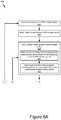
- FIGS. 6A and 6Bdepict a flow diagram of an example method for using a failed storage device in the P2P storage system shown in FIGS. 1 and 4 to perform an exemplary storage-centric task (specifically, a pattern matching task), in accordance with an embodiment.
- FIG. 7depicts a flow diagram of an example method for performing a data management request (e.g., data transfer request) in accordance with a distributed global flash translation layer (FTL) data management scheme for the computing system shown in FIGS. 1 and 4 , in accordance with an embodiment.
- a data management requeste.g., data transfer request
- FTLdistributed global flash translation layer
- Novel data processing technologysuch as but not limited to systems, devices, and methods for using a failed storage device in a peer-to-peer (P2P) storage system to perform a storage-centric task are disclosed. While this technology is described below in the context of a particular system architecture in various cases, it should be understood that the systems and methods can be applied to other architectures and organizations of hardware. More specifically, it should be noted that while the following description is made with reference to certain embodiments, the present disclosure may apply to any storage system that implements data redundancy known or contemplated.
- P2Ppeer-to-peer
- FIG. 1depicts a block diagram of an example computing system 100 including a host 101 and a P2P storage system 110 , in accordance with an embodiment. As described in detail below with reference to FIGS. 5-6 , the computing system 100 may be used in connection with a method for using a failed storage device in a P2P storage system to perform a storage-centric task.
- a “storage-centric task”may refer to any sequence of operations (e.g., a “job”, a “process”, etc.) that involve the transfer and/or processing of data stored in storage devices or systems.
- Examples of storage-centric tasksinclude pattern matching, map/reduce, compression/decompression, encryption/decryption, failed storage device rebuild, etc.
- the host 101may be one or more of any suitable computer devices or systems, such as a server computer, a desktop computer, a laptop computer, a tablet computer, a mobile telephone, or any other electronic device capable of making requests to the P2P storage system.
- the host 101may include one or more processors, one or more memory devices, and any other suitable components to add functionality to the host 101 .
- the host 101may be communicatively coupled to the P2P storage system 110 through a network, such as a local-area network (LAN), wide-area network (WAN), switched fabric, wired or wireless network, private or public network, etc.
- a networksuch as a local-area network (LAN), wide-area network (WAN), switched fabric, wired or wireless network, private or public network, etc.
- the host 101may execute one or more applications that make storage requests (e.g., read, write, etc.) to the P2P storage system.
- the one or more applicationsmay be dedicated software applications running on the host 101 or may alternatively reside on other suitable computing devices and may be remotely executed by the host 101 .
- the P2P storage system 110may comprise a system controller 120 and a plurality of storage devices 140 a , 140 b , and 140 c coupled through a transport medium, such as an internal fabric based on Ethernet, InfiniBand, Peripheral Component Interconnect Express (PCIe), Non-Volatile Memory Express Over Fabric (NVMeOF), etc.
- a transport mediumsuch as an internal fabric based on Ethernet, InfiniBand, Peripheral Component Interconnect Express (PCIe), Non-Volatile Memory Express Over Fabric (NVMeOF), etc.
- PCIePeripheral Component Interconnect Express
- NVMeOFNon-Volatile Memory Express Over Fabric
- the system controller 120may comprise one or more computing devices and/or software (collectively referred to as “logic” in the present disclosure) configured to manage the operation of and provide an external interface to (e.g., for communication with the host 101 ) the storage devices 140 a , 140 b , and 140 c .
- the system controller 120may coordinate and perform various operations of the storage devices 140 a , 140 b , and 140 c including data redundancy and/or recovery, storage device rebuild, and/or garbage collection.
- system controller 120may coordinate communications between the host 101 and the storage devices 140 a , 140 b , and 140 c , including forwarding read or write requests received from the host 101 to the corresponding storage device (including performing any necessary address translation as described further below), and retrieving data from the storage devices in a logical manner (e.g., blocks may be assembled into a stripe) before being returned to the host 101 .
- the system controller 120may be a Non-Volatile Memory Express (NVMe) controller.
- NVMeNon-Volatile Memory Express
- the system controller 120may coordinate its actions with the actions of the other components in the computer system 100 , such as the host 101 and/or the storage devices 140 a , 140 b , and 140 c , in performing the various storage-centric tasks as described below, using, for example, the distributed global FTL data management scheme as described below with reference to FIG. 7 .
- the system controller 120may not be a separate component as shown in FIG. 1 but instead may be integrated into the host 101 or in one or more of the storage devices 140 a , 140 b , and 140 c.
- Each of the plurality of storage devices 140 a , 140 b , and 140 cmay be a volatile or non-volatile non-transitory memory device with suitable characteristics, such as flash memory (e.g., solid-state drive (SSD)), persistent memory (PM), and/or hard disk media including shingled magnetic recording (SMR) disks, hybrid storage devices, etc.
- the storage devices 140 a , 140 b , and 140 cmay be communicatively coupled to each other and to the system controller 120 through a transport medium, such as an internal fabric based on Ethernet, InfiniBand, PCIe, NVMeOF, etc.
- Each storage device 140includes a device controller 142 and a storage medium 143 .
- the device controller 142may comprise one or more computing devices and/or software (collectively referred to as “logic” in the present disclosure) configured to manage the operation of the storage medium 143 and provide an external interface to the respective storage device 140 .
- these operationsmay include performing peer-to-peer (P2P) communications (e.g., P2P data transfers) with other storage devices in the P2P storage system.
- P2Ppeer-to-peer
- the storage medium 143may comprise one or more volatile or non-volatile memory media having physical or logical portions for storing data, such as dies, disks, memory cells, sectors, and/or pages.
- datamay be organized in the storage medium 143 of each storage device 140 in the form of one or more blocks 144 . Further, the blocks 144 may be written to the storage devices in the P2P storage system 110 in the form of stripes using a suitable data structuring methodology such as log-structuring.
- the P2P storage system 110may be configured using a suitable redundancy scheme such as RAID or erasure coding such that in the event of a failure of one or more storage devices in the P2P storage system 110 , a data reconstruction and/or rebuild process may be performed to recover the data from the failed storage device(s).
- a suitable redundancy schemesuch as RAID or erasure coding
- a “failed storage device”may refer to any storage device in the P2P storage system that is not properly functioning in any respect, including: (1) a storage device that is still operational but may be deemed “failed” based on an early warning indication and (2) a storage device that has only partially failed.
- the failed storage devicemay include one or more storage resources (e.g., storage medium 143 ) that have partially or completely failed and one or more compute resources (e.g., device controller 142 ) that remain at least partially functioning (e.g., able to perform at least some of their intended functions).
- the one or more storage devices in the P2P storage system other than the failed storage devicemay be referred to as “functioning storage devices.”
- the storage device 140 bcorresponds to the failed storage device (henceforth to be referred to as failed storage device 140 ′) and one or more of the storage devices 140 a and 140 c correspond to the functioning storage device(s) (henceforth to be referred to as functioning storage device 140 ′′).
- other storage devicesmay correspond to the failed storage device and to the functioning storage device(s).
- the otherwise idle compute resources of the failed storage devicemay be used to perform storage-centric tasks as described below with reference to FIGS. 5-6 . As noted earlier, this is in contrast to conventional systems in which the failed storage device is no longer used after a failure is detected.
- FIG. 2depicts a block diagram of an example system controller 120 for the P2P storage system 110 shown in FIG. 1 , in accordance with an embodiment.
- the system controller 120may be used to manage the operation of and provide an external interface to (e.g., for communication with the host 101 ) the storage devices 140 a , 140 b , and 140 c .
- the system controller 120may coordinate its actions with the actions of the other components in the computer system 100 , such as the host 101 and/or the storage devices 140 a , 140 b , and 140 c , in performing the various storage-centric tasks as described below, using, for example, the distributed global FTL data management scheme as described below with reference to FIG. 7 .
- the system controller 120may comprise, among other components, one or more interface(s) 205 , a processor 210 , a memory 220 containing software, firmware and/or data including, but not limited to, a storage management engine 222 .
- a bus 250may be used to communicatively couple the various components of the system controller 120 .
- the system controller 120may include alternative, additional and/or fewer components depending on the configuration, such as configurations combining elements, implementing elements in hardware vs. software, etc.
- the one or more interface(s) 205may communicatively couple the system controller 120 to the host 101 and/or the storage devices 140 a , 140 b , and 140 c .
- the one or more interface(s) 205may include, but are not limited to, input/output (I/O) interface circuitry that uses appropriate communications protocol(s) for communicating with the host 101 and/or the storage devices 140 a , 140 b , and 140 c.
- I/Oinput/output
- the processor 210may be used to execute the instructions of various software programs contained in the memory 220 .
- the processor 210may include one or more processing units and/or cores, programmable integrated circuits such as application-specific integrated circuits (ASICs) or field-programmable gate arrays (FPGAs), or some combination thereof.
- ASICsapplication-specific integrated circuits
- FPGAsfield-programmable gate arrays
- the processor 210may be based on various computing architectures including a complex instruction set computer (CISC) architecture, a reduced instruction set computer (RISC) architecture, or an architecture implementing a combination of instruction sets. It should be understood that other configurations of the processor 210 are possible.
- the memory 220may store software programs, firmware and/or data that are executed or otherwise processed by the processor 210 .
- the memory 220may comprise, for example, volatile memory such as dynamic random-access memory (DRAM) device(s), static random-access memory (SRAM) device(s), non-volatile memory such as electrically erasable programmable read-only memory (EEPROM) or flash memory devices, a combination of the foregoing, and/or some other suitable type of data storage medium.
- DRAMdynamic random-access memory
- SRAMstatic random-access memory
- EEPROMelectrically erasable programmable read-only memory
- flash memory devicesa combination of the foregoing, and/or some other suitable type of data storage medium.
- the storage management engine 222 contained in memory 220may include routines and/or instructions that when executed by the processor 210 may perform one or more of the various memory management operations for the storage devices 140 a , 140 b , and 140 c , including operations relating to address translation, data recovery and reconstruction, garbage collection and/or load balancing.
- the storage management engine 222may include an address map 225 and a load balancing module 226 .
- the address map 225may contain address information used by the storage management engine 222 to translate logical addresses or name spaces received in connection with read or write requests received from the host 101 into physical addresses for accessing storage devices in the P2P storage system 110
- the load balancing module 226may implement a load balancing policy for the P2P storage system 110 .
- the load balancing module 226may perform functions including monitoring the load of the storage devices in the P2P storage system and assigning and managing tasks received from the host 101 and to be performed by one or more of the storage devices in the P2P storage system 110 based on the measured loads. These load balancing functions will be described in more detail below with reference to FIGS. 5-6 .
- one or more hardware logic module(s) 230such as ASICs, FPGAs, etc., may be employed in place of, or as a supplement to, the software and/or firmware in the memory 220 to perform one or more of the aforementioned functions provided by the storage management engine 222 .
- FIG. 3depicts a block diagram of an example device controller 142 for the P2P storage system 110 shown in FIG. 1 , in accordance with an embodiment.
- the device controller 142may be used to manage the operation of and provide an external interface to the respective storage device 140 .
- the device controller 142may comprise, among other components, one or more interface(s) 305 , a processor 310 , a controller memory buffer (CMB) 315 , a memory 320 containing software, firmware and/or data including a media management engine 322 , and a P2P data transfer engine 324 .
- a bus 350may be used to communicatively couple the various components of the device controller 142 .
- the device controller 142may include alternative, additional and/or fewer components depending on the configuration, such as configurations combining elements, implementing elements in hardware vs. software, etc.
- the one or more interface(s) 305may communicatively couple the device controller 142 to the system controller 120 and/or the other storage devices in the P2P storage system 110 .
- the one or more interface(s) 305may include, but are not limited to, I/O interface circuitry that uses appropriate communications protocol(s) (e.g., Ethernet, InfiniBand, PCIe, etc.) for communicating with the system controller 120 and/or the other storage devices.
- the processor 310may be used to execute the instructions of various software programs contained in the memory 320 .
- the processor 310may include one or more processing units and/or cores, programmable integrated circuits such as application-specific integrated circuits (ASICs) or field-programmable gate arrays (FPGAs), or some combination thereof.
- ASICsapplication-specific integrated circuits
- FPGAsfield-programmable gate arrays
- the processor 310may be based on various computing architectures including a complex instruction set computer (CISC) architecture, a reduced instruction set computer (RISC) architecture, or an architecture implementing a combination of instruction sets. It should be understood that other configurations of the processor 310 are possible.
- the CMB 315may include one or more memory buffers that are used to temporarily store source or destination data involved in P2P read or write data transfers. In some embodiments, the CMB 315 may be accessible directly from outside of the storage device for performing direct memory access (DMA) operations with another storage device in the P2P storage system 110 .
- DMAdirect memory access
- the memory 320may store software programs, firmware and/or data that are executed or otherwise processed by the processor 310 .
- the memory 320may comprise, for example, volatile memory such as dynamic random-access memory (DRAM) device(s), static random-access memory (SRAM) device(s), non-volatile memory such as electrically erasable programmable read-only (EEPROM) or flash memory devices, a combination of the foregoing, and/or some other suitable type of data storage medium.
- DRAMdynamic random-access memory
- SRAMstatic random-access memory
- EEPROMelectrically erasable programmable read-only
- flash memory devicesa combination of the foregoing, and/or some other suitable type of data storage medium.
- the media management engine 322 contained in memory 320may include routines and/or instructions that when executed by the processor 310 may perform one or more of the various memory management operations for the storage medium 143 , including operations relating to data recovery and reconstruction and device-level garbage collection.
- the P2P data transfer engine 324 contained in memory 320may include routines and/or instructions that when executed by the processor 310 may perform one or more actions for conducting P2P communications (e.g., P2P data transfers) with other storage devices in the P2P storage system 110 , such as translating logical addresses associated with P2P commands, issuing and executing P2P commands and data transfers, as described below with reference to FIG. 4 .
- the P2P data transfer engine 324can perform the P2P data transfers in various ways. For example, in some embodiments, the P2P data transfer engine 324 may operate in full initiator mode, which enables a storage device to connect, to create commands, and to send the commands to other storage devices.
- the host 101may set up shared memory areas in each storage device 140 , send one or more commands to a source storage device to read data in the source storage device to a shared memory area, and then initiate the sending of data from the shared memory area to a target storage device using DMA.
- one or more hardware logic module(s) 330such as ASICs, FPGAs, etc., may be employed in place of, or as a supplement to, the software and/or firmware in the memory 320 to perform one or more of the aforementioned functions provided by the media management engine 322 and/or P2P data transfer engine 324 .
- FIG. 4illustrates various host and P2P data transfers that may occur in connection with the method for using the failed storage device 140 ′ (e.g., storage device 140 b ) in the P2P storage system 110 shown in FIG. 1 to perform a storage-centric task (as described below with reference to FIGS. 5-6 ), in accordance with an embodiment.
- the storage device 140 bcorresponds to the failed storage device 140 ′ and one or more of the storage devices 140 a and 140 c correspond to the functioning storage device 140 ′′.
- other storage devicesmay correspond to the failed storage device and to the functioning storage device(s).
- the types of data transfers that may occur between the host 101 and the storage devices 140 a , 140 b , and 140 c in the P2P storage system 110include: (1) a read data transfer (indicated by the dashed arrow labeled “R”) and (2) a write data transfer (indicated by the dashed arrow labeled “W”).
- these data transfersmay be initiated by the issuance of one or more NVMe read commands or write commands by the system controller 120 as appropriate.
- these data transfersmay be performed by the host 101 in coordination with the storage management engine 222 in the system controller 120 .
- the types of P2P data transfers that may occur between storage devices in the P2P storage system 110include: (1) a read data transfer (indicated by the dashed arrow labeled “R”), (2) a write data transfer (indicated by the dashed arrow labeled “W”), and (3) a read/write data transfer (indicated by the dashed arrow labeled “R/W”).
- Rread data transfer
- Wwrite data transfer
- R/Wread/write data transfer
- these P2P data transfersmay be initiated by the issuance of one or more P2P read commands or write commands by the initiator device to the target device as appropriate. In some embodiments, these P2P data transfers may be performed by the P2P data transfer engine 324 in coordination with the CMB 315 of the device controller 142 of the corresponding storage devices in the P2P storage system 110 .
- the failed storage device 140 ′corresponds to the initiator device and the functioning storage device 140 ′′ corresponds to the target device.
- the initiator device and the target devicemay differ depending on the particular transaction being performed.
- FIGS. 5A and 5Bdepict a flow diagram of an example method 500 for using the failed storage device 140 ′ in the P2P storage system 110 shown in FIGS. 1 and 4 to perform a storage-centric task, in accordance with an embodiment.
- one or more of the blocks in the method 500may be performed in accordance with the distributed global FTL data management scheme as described below with reference to FIG. 7 .
- a “storage-centric task”may refer to any sequence of operations (e.g., a “job”, a “process”, etc.) that involve the transfer and/or processing of data stored in storage devices or systems (e.g., P2P storage system 110 ).
- the storage-centric taskmay originate from the host 101 (in connection with the execution an application by the host) or in some cases, be transferred from a functioning storage device 140 ′′ in the P2P storage system 110 .
- Examples of storage-centric tasksinclude pattern matching, map/reduce, compression/decompression, encryption/decryption, failed storage device rebuild, etc.
- the storage-centric taskmay be a “new” task that has not been previously performed by the failed storage device 140 ′ prior to the failure of the failed storage device.
- the storage-centric taskmay be defined by a series of computer-executable instructions and addresses of input data and/or output data.
- the computer-executable instructionsmay comprise program code executable by the functioning compute resource (e.g., device controller 142 ) in the failed storage device 140 ′.
- the P2P storage system 110may be in a normal operating state, in which the storage devices in the P2P storage system 110 are properly functioning and tasks may be assigned to and performed by one or more of the storage devices according to a load balancing policy.
- the load balancing policy used by the P2P storage system 110may be static or dynamic and may be based on one or more load balancing schemes such as round robin, “balanced load”, etc.
- the “balanced load” policymay simply attempt to balance the processing and/or I/O load among the storage devices in the P2P storage system 110 , based on factors such as the number of tasks being performed, the latency, and/or the throughput of each storage device.
- the load balancing policy used during the normal operating state of the P2P storage system 110 in block 510may be the same as, or different from, the load balancing policy used to select and assign the storage-centric task, as discussed in block 531 below.
- the system controller 120detects the failed storage device 140 ′ in the P2P storage system 110 .
- the system controller 120may detect the failed storage device 140 ′ in coordination with the failed storage device through the use of one or more NVMe commands.
- the failed storage device 140 ′may refer to any storage device in the P2P storage system that is not properly functioning in any respect, including a storage device that is still operational but may be deemed “failed” based on an early warning indication.
- the failed storage device 140 ′may include one or more compute resources (e.g., device controller 142 ) and/or storage resources (e.g., storage medium 143 ) that remain at least partially functioning, e.g., able to perform at least some of their intended function(s).
- compute resourcese.g., device controller 142
- storage resourcese.g., storage medium 143
- the system controller 120assigns a storage-centric task to the failed storage device 140 ′.
- the block 530may be performed by the load balancing module 226 in the system controller 120 .
- Block 530includes blocks 531 - 532 , which are described next.
- the system controller 120selects a storage-centric task for assignment to the failed storage device 140 ′ based on the load balancing policy for the P2P storage system 110 .
- the load balancing policy used to select and assign the storage-centric taskmay be the same as, or different from, the load balancing policy used during the normal operating state of the P2P storage system 110 (in block 510 ).
- the detection of the failed storage devicemay cause a change (e.g., an increase) in a weighting or bias of the load balancing policy towards assigning a storage-centric task to the failed storage device 140 ′ as compared with the normal operating state of the P2P storage system 110 .
- this featuremay result in improved system performance and/or resource utilization through the continued use of the failed storage device 140 ′ after the device's failure by employing the otherwise idle compute resources of the failed storage device to perform storage-centric tasks.
- the system controller 120sends information (e.g., one or more instructions and input and/or output data addresses) associated with the storage-centric task to the failed storage device 140 ′.
- the storage management engine 222 in the system controller 120may send the information associated with the storage-centric task by issuing a series of NVMe write commands (as described above with reference to FIG. 4 ) containing the information associated with the storage-centric task to the failed storage device 140 ′. In this manner, the failed storage device 140 ′ is provided with the information necessary to perform the storage-centric task in block 540 .
- Block 540upon determining that the storage-centric task has been assigned to the failed storage device 140 ′, the failed storage device performs the storage-centric task responsive to P2P communications with the functioning storage device 140 ′′.
- the storage-centric taskmay be performed by a functioning compute resource (e.g., device controller 142 ) in the failed storage device 140 ′.
- Block 540includes blocks 541 - 545 , which are described next.
- the input data and output data associated with the storage-centric taskare both located on the functioning storage device 140 ′′.
- the input data and output datamay be located on different functioning storage devices in the P2P storage system 110 , such as storage devices 140 a and 140 c , respectively.
- the failed storage device 140 ′corresponds to the initiator device and the functioning storage device 140 ′′ corresponds to the target device.
- the failed storage device 140 ′determines a location (e.g., in functioning storage device 140 ′′) in the P2P storage system 110 of the input data associated with the storage-centric task.
- the location of the input datamay be determined from the input data address(es) associated with the storage-centric task received from the system controller 120 (e.g., in block 532 ).
- the location of the input datamay be determined by performing an address translation operation using the P2P data transfer engine 324 in the failed storage device 140 ′.
- the failed storage device 140 ′receives the input data associated with the storage-centric task via P2P communications with the functioning storage device 140 ′′.
- the P2P communicationsmay comprise a series of one or more P2P read commands (as described above with reference to FIG. 4 ) issued by the failed storage device 140 ′ to the functioning storage device 140 ′′.
- the P2P read commandsmay be performed by the P2P data transfer engine 324 in coordination with the CMB 315 of the device controller 142 of the corresponding storage devices.
- the failed storage device 140 ′performs the storage-centric task using the input data received from the functioning storage device 140 ′′, generating output data based on the performing of the storage-centric task.
- the storage-centric taskmay be performed using the functioning compute resource (e.g., device controller 142 ) in the failed storage device 140 ′ based on the one or more instructions associated with the storage-centric task received from the system controller 120 (e.g., in block 532 ).
- the failed storage device 140 ′may perform the storage-centric task on the blocks 144 of the input data individually as they are received or on the entire set of the input data all at once (e.g., using DMA).
- the output datamay be temporarily stored in a buffer (e.g., CMB 315 ) in the failed storage device 140 ′.
- blocks 542 and 543are shown separately in the figure, it should be noted that in some embodiments, at least some the operations in these blocks may be performed concurrently by the failed storage device 140 ′ in performing the storage-centric task.
- the failed storage device 140 ′sends the output data generated by the storage-centric task via P2P communications with the functioning storage device 140 ′′.
- the P2P communicationsmay comprise a series of one or more P2P write commands (as described above with reference to FIG. 4 ) issued by the failed storage device 140 ′ to the functioning storage device 140 ′′.
- the P2P write commandsmay be performed by the P2P data transfer engine 324 in coordination with the CMB 315 of the device controller 142 of the corresponding storage devices.
- a location of the output data in the functioning storage device 140 ′′may be determined from the output data address(es) associated with the storage-centric task received from the system controller 120 (e.g., in block 532 ). In some embodiments, the location of the output data may be determined by performing an address translation operation using the P2P data transfer engine 324 in the failed storage device 140 ′ (as described above in block 541 ).
- block 545the functioning storage device 140 ′′ sends the output data generated by the storage-centric task to the host 101 , from which the task originated.
- block 545may be performed by the functioning storage device 140 ′′ in coordination with the system controller 120 through the use of one or more NVMe commands.
- the system controller 120detects a completion of the storage-centric task by the failed storage device 140 ′.
- the system controller 120may detect the completion of the storage-centric task by issuing one or more NVMe commands to the failed storage device 140 ′.
- the system controller 120determines if the failed storage device 140 ′ has been repaired or replaced in the P2P storage system 110 . If this is the case, the system controller 120 returns control to block 510 (e.g., normal operation of the P2P storage system 110 ). If this is not the case, however, the system controller returns control to block 530 , in which the system controller assigns another storage-centric task to the failed storage device 140 ′.
- FIGS. 6A and 6Bdepict a flow diagram of an example method 600 for using the failed storage device 140 ′ in the P2P storage system 110 shown in FIGS. 1 and 4 to perform an exemplary storage-centric task (specifically, a pattern matching task), in accordance with an embodiment.
- the pattern matching taskmay comprise a sequence of operations originating from the host 101 that counts all occurrences of the word “cat” in an encrypted compressed dataset stored on the functioning storage device 140 ′′.
- one or more of the blocks in the method 600may be performed in accordance with the distributed global FTL data management scheme as described below with reference to FIG. 7 .
- the method 600is an embodiment of the method 500 described above with reference to FIGS. 5A and 5B , as applied specifically to the pattern matching task.
- the P2P storage system 110may be in a normal operating state, in which the storage devices in the P2P storage system 110 are properly functioning and tasks may be assigned to and performed by one or more of the storage devices according to a load balancing policy.
- the load balancing policymay be as described above with reference to blocks 510 and 531 in FIGS. 5A and 5B .
- the system controller 120detects the failed storage device 140 ′ in the P2P storage system 110 .
- the system controller 120may detect the failed storage device 140 ′ as described above with reference to block 520 in FIGS. 5A and 5B .
- Block 630the system controller 120 assigns the pattern matching task to the failed storage device 140 ′.
- Block 630includes blocks 631 - 632 , which are described next.
- the system controller 120selects the pattern matching task for assignment to the failed storage device 140 ′ based on the load balancing policy for the P2P storage system 110 described in block 610 . Normally, the system controller 120 would assign the pattern matching task to the functioning storage device 140 ′′ because that is where the dataset associated with the pattern matching task is stored. Instead, however, the system controller 120 assigns the pattern matching task to the failed storage device 140 ′ because it determines that the functioning storage device 140 ′′ is sufficiently busy performing other tasks and the functioning compute resource in the failed storage device 140 ′ is idle, and thus the data decryption/decompression associated with the pattern matching task would be performed more quickly by the failed storage device 140 ′.
- the system controller 120issues a series of NVMe write commands (as described above with reference to FIG. 4 ) containing information (e.g., one or more instructions and input and/or output data addresses) associated with the pattern matching task to the failed storage device 140 ′.
- informatione.g., one or more instructions and input and/or output data addresses
- the failed storage device 140 ′is provided with the information necessary to perform the storage-centric task in block 640 .
- Block 640the failed storage device 140 ′ performs the pattern matching task responsive to P2P communications with the functioning storage device 140 ′′, in which the dataset associated with the pattern matching task is stored.
- Block 640includes blocks 641 - 645 , which are described next.
- the failed storage device 140 ′determines a location in the functioning storage device 140 ′′ of the dataset associated with the pattern matching task.
- the failed storage device 140 ′issues a series of one or more P2P read commands (as described above with reference to FIG. 4 ) to the functioning storage device 140 ′′ to receive one or more blocks 144 in the dataset from the functioning storage device.
- the failed storage device 140 ′begins performing the pattern matching task by performing a “cat” word search on the one or more blocks 144 in the dataset received from the functioning storage device 140 ′′.
- block 643 ( 1 )may first involve decrypting and/or decompressing the blocks in the dataset.
- the pattern matching taskmay be performed using the functioning compute resource (e.g., device controller 142 ) in the failed storage device 140 ′ based on the one or more instructions associated with the pattern matching task received from the system controller 120 (e.g., in block 632 ).
- the failed storage device 140 ′may perform the pattern matching task on the blocks of the dataset individually as they are received or on the entire set of blocks all at once (e.g., using DMA).
- the output datamay be temporarily stored in a buffer (e.g., CMB 315 ) in the failed storage device 140 ′.
- the failed storage device 140 ′prepares a list of blocks in the dataset found to contain the word “cat.”
- blocks 642 , 643 ( 1 ), and 643 ( 2 )are shown separately in the figure, it should be noted that in some embodiments, at least some of the operations in these blocks may be performed concurrently by the failed storage device 140 ′ in performing the pattern matching task.
- the failed storage device 140 ′issues a series of one or more P2P write commands to the functioning storage device 140 ′′ to send the list of blocks 144 in the dataset that were found to contain the word “cat” to the functioning storage device.
- block 645the functioning storage device 140 ′′ sends the list of blocks 144 in the dataset found to contain the word “cat” to the host 101 , from which the task originated.
- block 645may be performed by the functioning storage device 140 ′′ in coordination with the system controller 120 using one or more NVMe commands.
- the system controller 120detects a completion of the pattern matching task by the failed storage device 140 ′.
- the system controller 120may detect the completion of the storage-centric task by issuing one or more NVMe commands to the failed storage device 140 ′.
- the system controller 120determines if the failed storage device 140 ′ has been repaired or replaced in the P2P storage system 110 . If this is the case, the system controller 120 returns control to block 510 (e.g., normal operation of the P2P storage system 110 ). If this is not the case, however, the system controller returns control to block 530 , in which the system controller 120 assigns another storage-centric task to the failed storage device 140 ′.
- FIG. 7depicts a flow diagram of an example method 700 for performing a data management request (e.g., data transfer request) in accordance with a distributed global flash translation layer (FTL) data management scheme for the computing system 100 shown in FIG. 1 , in accordance with an embodiment.
- a data management requeste.g., data transfer request
- FTLdistributed global flash translation layer
- FIG. 7most of the blocks in the method 700 are performed by the system controller 120 , although in other embodiments one or more of the blocks in the method may be performed by other devices (e.g., host 101 or storage device 140 ) in the storage system 110 .
- the system controller 120may receive a data management request (e.g., read request) from the host 101 .
- a data management requeste.g., read request
- the system controller 120may determine (e.g., using the storage management engine 222 ), based on the data management request, one or more storage devices 140 in the storage system 110 and one or more data management operations to be performed by the one or more storage devices 140 .
- the system controller 120in order to determine the one or more storage devices 140 , receives an input logical address from the host 101 and indexes the address map 225 , which maps logical addresses to storage devices, using the input logical address to identify the one or more storage devices 140 .
- the system controller 120uses at least a portion of the input logical address to identify the one or more storage devices 140 .
- block 730the system controller 120 may initiate performance of data management operation(s) corresponding to the data management request.
- block 730includes sending one or more data management commands to the one or more storage devices 140 and initiating one or more data transfers (either before or after sending the one or more data management commands).
- the one or more data transfersmay include one or more operations such as a direct memory access (DMA) operation to transfer data between a memory buffer of a respective storage device 140 in the storage system 110 and a memory buffer of the host 101 , and/or an internal data transfer between two or more of the storage devices 140 in the storage system 110 .
- DMAdirect memory access
- the one or more data transfersincludes a DMA operation to transfer data between a memory buffer of a respective storage device 140 in the storage system 110 and a memory buffer of the host 101 , and/or an internal data transfer between two or more of the storage devices 140 in the storage system 110 .
- the system controller 120determines, based on the address map 225 , a set of blocks located in a respective storage device 140 in the storage system 110 containing the requested data.
- the address map 225maps one or more global logical addresses, identified by the read request (received from the host 101 ), to one or more storage devices 140 in the P2P storage system 110 , and optionally to one or more local logical addresses in each such storage device.
- the local logical addressesare mapped, by the respective storage device 140 , to physical addresses in the storage device using logical-to-physical mapping mechanisms in the storage device.
- the system controller 120initiates the computation of the address map 225 .
- the address mapis computed by one or more devices external to the system controller 120 .
- the address map 225is stored/located in the respective storage device 140 .
- the system controller 120sends one or more read commands to the respective storage device 140 to perform the read operation on the set of blocks.
- the system controller 120translates the read request received from the host 101 into the one or more read commands, using a predefined command translation process.
- the device controller 142 of the respective storage device 140responds to the one or more read commands by reading the corresponding data from the set of blocks in the respective storage device.
- the system controller 120receives a finish notification from the respective storage device 140 that indicates the execution of the read command sent to the respective storage device is complete, and that the resulting read data is stored in a memory buffer of the device controller 142 of the respective storage device.
- block 780the system controller 120 , after receiving the finish notification, initiates a data transfer using a DMA operation to transfer (e.g., send) the read data to the host 101 that sent the read request.
- block 780includes the system controller 120 sending a data transfer command to a respective network interface controller (not shown) in the storage system 110 to transfer the read data from a memory buffer of the system controller 120 to a memory buffer of the host 101 , using DMA or remote direct memory access (RDMA) to transfer the read data.
- RDMAremote direct memory access
- the present disclosureimproves system performance by assigning storage-centric tasks to, rather than away from (per conventional systems), the failed storage device upon detecting the failure.
- the failed storage devicecan perform tasks more efficiently than another, still functioning storage device in the storage system because the failed storage device no longer has a regular input/output (I/O) load (e.g., compression/decompression or encryption/decryption, which are very computation intensive) due to the failure of its storage medium.
- I/Oinput/output
- the present disclosureimproves system resource utilization through the continued use of the failed storage device after the device's failure by employing the otherwise idle compute resources of the failed storage device to perform storage-centric tasks.
- the present disclosuretakes advantage of the fact that despite a failure in its storage medium, other compute, storage, and/or I/O resources of the failed storage device may remain operational.
- a processcan generally be considered a self-consistent sequence of operations leading to a result.
- the operationsmay involve physical manipulations of physical quantities. These quantities take the form of electrical or magnetic signals capable of being stored, transferred, combined, compared, and otherwise manipulated. These signals may be referred to as being in the form of bits, values, elements, symbols, characters, terms, numbers or the like.
- the disclosed technologiesmay also relate to an apparatus for performing the operations herein.
- This apparatusmay be specially constructed for the required purposes, or it may include a general-purpose computer selectively activated or reconfigured by a computer program stored in the computer.
- a computer programmay be stored in a computer readable storage medium, for example, but is not limited to, any type of disk including floppy disks, optical disks, CD ROMs, and magnetic disks, read-only memories (ROMs), random access memories (RAMs), erasable programmable read-only memories (EPROMs), electrically erasable programmable read-only memories (EEPROMs), magnetic or optical cards, flash memories including USB keys with non-volatile memory or any type of media suitable for storing electronic instructions, each coupled to a computer system bus.
- the disclosed technologiescan take the form of an entirely hardware implementation, an entirely software implementation or an implementation containing both hardware and software elements.
- the technologyis implemented in software, which includes but is not limited to firmware, resident software, microcode, etc.
- a computer-usable or computer-readable mediumcan be any apparatus that can contain, store, communicate, propagate, or transport the program for use by or in connection with the instruction execution system, apparatus, or device.
- a computing system or data processing system suitable for storing and/or executing program codewill include at least one processor (e.g., a hardware processor) coupled directly or indirectly to memory elements through a system bus.
- the memory elementscan include local memory employed during actual execution of the program code, bulk storage, and cache memories which provide temporary storage of at least some program code in order to reduce the number of times code must be retrieved from bulk storage during execution.
- I/O devicesincluding but not limited to keyboards, displays, pointing devices, etc.
- I/O controllerscan be coupled to the system either directly or through intervening I/O controllers.
- Network adaptersmay also be coupled to the system to enable the data processing system to become coupled to other data processing systems or remote printers or storage devices through intervening private or public networks.
- Modems, cable modems and Ethernet cardsare just a few of the currently available types of network adapters.
- storage mediastorage device, and data blocks are used interchangeably throughout the present disclosure to refer to the physical media upon which the data is stored.
- modules, routines, features, attributes, methodologies and other aspects of the present technologycan be implemented as software, hardware, firmware or any combination of the three.
- a componentan example of which is a module
- the componentcan be implemented as a standalone program, as part of a larger program, as a plurality of separate programs, as a statically or dynamically linked library, as a kernel loadable module, as a device driver, and/or in every and any other way known now or in the future in computer programming.
- the present techniques and technologiesare in no way limited to implementation in any specific programming language, or for any specific operating system or environment. Accordingly, the disclosure of the present techniques and technologies is intended to be illustrative, but not limiting.
Landscapes
- Engineering & Computer Science (AREA)
- Theoretical Computer Science (AREA)
- Computer Networks & Wireless Communication (AREA)
- Signal Processing (AREA)
- Physics & Mathematics (AREA)
- General Engineering & Computer Science (AREA)
- General Physics & Mathematics (AREA)
- Computing Systems (AREA)
- Quality & Reliability (AREA)
- Human Computer Interaction (AREA)
- Mathematical Physics (AREA)
- Hardware Redundancy (AREA)
- Information Retrieval, Db Structures And Fs Structures Therefor (AREA)
Abstract
Description
Claims (20)
Priority Applications (4)
| Application Number | Priority Date | Filing Date | Title |
|---|---|---|---|
| US16/054,892US10824526B2 (en) | 2018-08-03 | 2018-08-03 | Using failed storage device in peer-to-peer storage system to perform storage-centric task |
| DE112019000194.9TDE112019000194T5 (en) | 2018-08-03 | 2019-06-01 | Use a failed storage device in a peer-to-peer storage system to perform a storage-centric task |
| PCT/US2019/035088WO2020027913A1 (en) | 2018-08-03 | 2019-06-01 | Using failed storage device in peer-to-peer storage system to perform storage-centric task |
| CN201980006393.8ACN111512289B (en) | 2018-08-03 | 2019-06-01 | Using failed storage devices in peer-to-peer storage systems to perform storage-centric tasks |
Applications Claiming Priority (1)
| Application Number | Priority Date | Filing Date | Title |
|---|---|---|---|
| US16/054,892US10824526B2 (en) | 2018-08-03 | 2018-08-03 | Using failed storage device in peer-to-peer storage system to perform storage-centric task |
Publications (2)
| Publication Number | Publication Date |
|---|---|
| US20200042412A1 US20200042412A1 (en) | 2020-02-06 |
| US10824526B2true US10824526B2 (en) | 2020-11-03 |
Family
ID=69228706
Family Applications (1)
| Application Number | Title | Priority Date | Filing Date |
|---|---|---|---|
| US16/054,892Active2038-11-24US10824526B2 (en) | 2018-08-03 | 2018-08-03 | Using failed storage device in peer-to-peer storage system to perform storage-centric task |
Country Status (4)
| Country | Link |
|---|---|
| US (1) | US10824526B2 (en) |
| CN (1) | CN111512289B (en) |
| DE (1) | DE112019000194T5 (en) |
| WO (1) | WO2020027913A1 (en) |
Cited By (1)
| Publication number | Priority date | Publication date | Assignee | Title |
|---|---|---|---|---|
| US11016674B2 (en) | 2018-07-20 | 2021-05-25 | EMC IP Holding Company LLC | Method, device, and computer program product for reading data |
Families Citing this family (22)
| Publication number | Priority date | Publication date | Assignee | Title |
|---|---|---|---|---|
| US9825913B2 (en) | 2014-06-04 | 2017-11-21 | Nicira, Inc. | Use of stateless marking to speed up stateful firewall rule processing |
| US9692698B2 (en) | 2014-06-30 | 2017-06-27 | Nicira, Inc. | Methods and systems to offload overlay network packet encapsulation to hardware |
| US11038845B2 (en) | 2016-02-23 | 2021-06-15 | Nicira, Inc. | Firewall in a virtualized computing environment using physical network interface controller (PNIC) level firewall rules |
| US11327683B2 (en)* | 2019-09-27 | 2022-05-10 | Dell Products L.P. | RAID storage-device-assisted read-modify-write system |
| US11262946B2 (en)* | 2019-11-25 | 2022-03-01 | Micron Technology, Inc. | Cache-based memory read commands |
| US11962518B2 (en) | 2020-06-02 | 2024-04-16 | VMware LLC | Hardware acceleration techniques using flow selection |
| US11606310B2 (en) | 2020-09-28 | 2023-03-14 | Vmware, Inc. | Flow processing offload using virtual port identifiers |
| US20220100432A1 (en) | 2020-09-28 | 2022-03-31 | Vmware, Inc. | Distributed storage services supported by a nic |
| US11636053B2 (en) | 2020-09-28 | 2023-04-25 | Vmware, Inc. | Emulating a local storage by accessing an external storage through a shared port of a NIC |
| US11875172B2 (en) | 2020-09-28 | 2024-01-16 | VMware LLC | Bare metal computer for booting copies of VM images on multiple computing devices using a smart NIC |
| US11593278B2 (en) | 2020-09-28 | 2023-02-28 | Vmware, Inc. | Using machine executing on a NIC to access a third party storage not supported by a NIC or host |
| US12021759B2 (en) | 2020-09-28 | 2024-06-25 | VMware LLC | Packet processing with hardware offload units |
| US11863376B2 (en) | 2021-12-22 | 2024-01-02 | Vmware, Inc. | Smart NIC leader election |
| US12229578B2 (en) | 2021-12-22 | 2025-02-18 | VMware LLC | Teaming of smart NICs |
| US11995024B2 (en) | 2021-12-22 | 2024-05-28 | VMware LLC | State sharing between smart NICs |
| CN114490222B (en)* | 2022-02-14 | 2022-11-15 | 无锡众星微系统技术有限公司 | PCIe P2P system test starting method and device |
| US12032483B2 (en)* | 2022-04-11 | 2024-07-09 | Samsung Electronics Co., Ltd. | Systems and methods for pre-populating address translation cache |
| US12373237B2 (en) | 2022-05-27 | 2025-07-29 | VMware LLC | Logical memory addressing by smart NIC across multiple devices |
| CN115048048A (en)* | 2022-05-31 | 2022-09-13 | 浙江大华技术股份有限公司 | Data storage system, data storage method, storage medium, and electronic device |
| US11928367B2 (en) | 2022-06-21 | 2024-03-12 | VMware LLC | Logical memory addressing for network devices |
| US11899594B2 (en) | 2022-06-21 | 2024-02-13 | VMware LLC | Maintenance of data message classification cache on smart NIC |
| US11928062B2 (en) | 2022-06-21 | 2024-03-12 | VMware LLC | Accelerating data message classification with smart NICs |
Citations (97)
| Publication number | Priority date | Publication date | Assignee | Title |
|---|---|---|---|---|
| US5388083A (en) | 1993-03-26 | 1995-02-07 | Cirrus Logic, Inc. | Flash memory mass storage architecture |
| US5530948A (en) | 1993-12-30 | 1996-06-25 | International Business Machines Corporation | System and method for command queuing on raid levels 4 and 5 parity drives |
| US5680539A (en) | 1995-07-11 | 1997-10-21 | Dell Usa, L.P. | Disk array system which performs data reconstruction with dynamic load balancing and user-specified disk array bandwidth for reconstruction operation to maintain predictable degradation |
| US5742752A (en) | 1995-12-29 | 1998-04-21 | Symbios Logic Inc. | Method for performing a RAID stripe write operation using a drive XOR command set |
| US6092215A (en) | 1997-09-29 | 2000-07-18 | International Business Machines Corporation | System and method for reconstructing data in a storage array system |
| US20020162075A1 (en) | 2001-04-30 | 2002-10-31 | Talagala Nisha D. | Storage array employing scrubbing operations at the disk-controller level |
| US20030135514A1 (en) | 2001-08-03 | 2003-07-17 | Patel Sujal M. | Systems and methods for providing a distributed file system incorporating a virtual hot spare |
| US6738937B1 (en) | 2000-12-01 | 2004-05-18 | Lsi Logic Corporation | Method for nondisruptive testing of device and host attachment to storage subsystems |
| US20050028048A1 (en) | 2003-07-29 | 2005-02-03 | Hitachi Global Storage Technologies | System and method for autonomous data scrubbing in a hard disk drive |
| US20050080991A1 (en) | 2003-10-09 | 2005-04-14 | International Business Machines Corporation | Method and apparatus for providing hardware aware logical volum mirrors |
| US20050114448A1 (en) | 2003-11-03 | 2005-05-26 | Apacheta Corporation | System and method for delegation of data processing tasks based on device physical attributes and spatial behavior |
| US20050114726A1 (en) | 2003-11-12 | 2005-05-26 | Ouchi Norman K. | Data recovery from multiple failed data blocks and storage units |
| US20060031722A1 (en) | 2004-08-04 | 2006-02-09 | International Business Machines Corporation | Apparatus, system, and method for active data verification in a storage system |
| US20060123142A1 (en) | 2004-12-06 | 2006-06-08 | Nvidia Corporation | Method and apparatus for providing peer-to-peer data transfer within a computing environment |
| US20070226413A1 (en) | 2006-03-21 | 2007-09-27 | International Business Machines Corporation | Offloading disk-related tasks from RAID adapter to distributed service processors in switched drive connection network enclosure |
| US20070245082A1 (en) | 2006-04-04 | 2007-10-18 | Margolus Norman H | Storage Assignment Technique for Scalable and Fault Tolerant Storage System |
| US7293133B1 (en) | 2003-12-31 | 2007-11-06 | Veritas Operating Corporation | Performing operations without requiring split mirrors in a multi-class file system |
| US20080005382A1 (en) | 2006-06-14 | 2008-01-03 | Hitachi, Ltd. | System and method for resource allocation in fault tolerant storage system |
| US20080034153A1 (en) | 1999-08-04 | 2008-02-07 | Super Talent Electronics Inc. | Flash Module with Plane-Interleaved Sequential Writes to Restricted-Write Flash Chips |
| US7434107B2 (en) | 2004-07-19 | 2008-10-07 | Dell Products L.P. | Cluster network having multiple server nodes |
| US20080250057A1 (en) | 2005-09-27 | 2008-10-09 | Rothstein Russell I | Data Table Management System and Methods Useful Therefor |
| US7454655B2 (en) | 2003-09-08 | 2008-11-18 | International Business Machines Corporation | Autonomic recovery of PPRC errors detected by PPRC peer |
| US20090070539A1 (en) | 2007-09-12 | 2009-03-12 | International Business Machines Corporation | Automated File Recovery Based on Subsystem Error Detection Results |
| US20090132760A1 (en) | 2006-12-06 | 2009-05-21 | David Flynn | Apparatus, system, and method for solid-state storage as cache for high-capacity, non-volatile storage |
| US20090150605A1 (en) | 2007-12-06 | 2009-06-11 | David Flynn | Apparatus, system, and method for converting a storage request into an append data storage command |
| US7571344B2 (en) | 2005-08-12 | 2009-08-04 | Silver Peak Systems, Inc. | Ensuring data integrity in network memory |
| US7596570B1 (en) | 2003-11-04 | 2009-09-29 | Emigh Aaron T | Data sharing |
| US7620841B2 (en) | 2006-01-19 | 2009-11-17 | International Business Machines Corporation | Re-utilizing partially failed resources as network resources |
| US20090307426A1 (en) | 2008-06-06 | 2009-12-10 | Pivot3 | Method and System for Rebuilding Data in a Distributed RAID System |
| US7680837B2 (en) | 2005-11-08 | 2010-03-16 | Nec Corporation | File management method for log-structured file system for sequentially adding and storing log of file access |
| US7783600B1 (en)* | 2006-02-27 | 2010-08-24 | Symantec Operating Corporation | Redundancy management service for peer-to-peer networks |
| US20100251073A1 (en) | 2004-03-12 | 2010-09-30 | Stolowitz Michael C | Disk controller methods and apparatus with improved striping, redundancy operations and interfaces |
| US20100280998A1 (en) | 2009-04-30 | 2010-11-04 | Microsoft Corporation | Metadata for data storage array |
| US20110029711A1 (en) | 2009-07-30 | 2011-02-03 | Cleversafe, Inc. | Method and apparatus for slice partial rebuilding in a dispersed storage network |
| US20110055178A1 (en) | 2009-08-27 | 2011-03-03 | Cleversafe, Inc. | Dispersed storage unit and methods with metadata separation for use in a dispersed storage system |
| US20110093742A1 (en) | 2009-10-16 | 2011-04-21 | Fujitsu Limited | Storage apparatus and control method for storage apparatus |
| US7984328B1 (en) | 2003-04-24 | 2011-07-19 | Netapp, Inc. | System and method for reducing unrecoverable media errors |
| US8086911B1 (en) | 2008-10-29 | 2011-12-27 | Netapp, Inc. | Method and apparatus for distributed reconstruct in a raid system |
| US20120011200A1 (en)* | 2010-07-06 | 2012-01-12 | Roxbeam Media Network Corporation | Method and apparatus for data storage in a peer-to-peer network |
| US20120079317A1 (en) | 2010-09-27 | 2012-03-29 | Chandrashekar Nelogal | System and method for information handling system redundant storage rebuild |
| US8289641B1 (en) | 2008-04-18 | 2012-10-16 | Network Appliance, Inc. | Partial data storage device failures and improved storage resiliency |
| US20120284460A1 (en) | 2011-05-02 | 2012-11-08 | Western Digital Technologies, Inc. | High performance path for command processing |
| US20130073894A1 (en) | 2011-09-20 | 2013-03-21 | Cloudbyte, Inc. | Techniques for achieving high availability with multi-tenant storage when a partial fault occurs or when more than two complete faults occur |
| US8473648B2 (en) | 2010-12-16 | 2013-06-25 | Lsi Corporation | System and method of I/O path virtualization between a raid controller and an environment service module in a storage area network |
| US20130179753A1 (en) | 2006-12-06 | 2013-07-11 | Fusion-Io, Inc. | Systems and methods for adaptive data storage |
| US8583853B1 (en) | 2009-05-22 | 2013-11-12 | Google Inc. | Error-handling for write-distribute command in raid mirroring |
| US20130339599A1 (en) | 2012-06-14 | 2013-12-19 | Lsi Corporation | Methods and systems for adaptive queue depth management |
| US20140012906A1 (en) | 2012-07-06 | 2014-01-09 | Aman Teja | Peer-to-peer architecture for web traffic management |
| US20140101369A1 (en) | 2012-10-05 | 2014-04-10 | Western Digital Technologies, Inc. | Methods, devices and systems for physical-to-logical mapping in solid state drives |
| US20140181041A1 (en) | 2012-12-21 | 2014-06-26 | Zetta, Inc. | Distributed data store |
| US20140181575A1 (en) | 2012-12-21 | 2014-06-26 | Microsoft Corporation | Data error detection and correction using hash values |
| WO2014110095A1 (en) | 2013-01-08 | 2014-07-17 | Violin Memory Inc. | Method and system for data storage |
| US20140237298A1 (en) | 2013-02-21 | 2014-08-21 | Sandisk Technologies Inc. | Methods, systems, and computer readable media for early detection of potential flash failures using an adaptive system level algorithm based on flash program verify |
| US20140258598A1 (en) | 2010-06-18 | 2014-09-11 | Lsi Corporation | Scalable storage devices |
| US8838931B1 (en) | 2012-03-30 | 2014-09-16 | Emc Corporation | Techniques for automated discovery and performing storage optimizations on a component external to a data storage system |
| US8904261B2 (en) | 2009-12-17 | 2014-12-02 | International Business Machines Corporation | Data management in solid state storage devices |
| US20140365719A1 (en) | 2013-01-28 | 2014-12-11 | Radian Memory Systems, LLC | Memory controller that provides addresses to host for memory location matching state tracked by memory controller |
| US20140379671A1 (en) | 2013-06-19 | 2014-12-25 | Exablox Corporation | Data scrubbing in cluster-based storage systems |
| US20150067244A1 (en) | 2013-09-03 | 2015-03-05 | Sandisk Technologies Inc. | Method and System for Migrating Data Between Flash Memory Devices |
| US20150205668A1 (en) | 2014-01-17 | 2015-07-23 | Netapp, Inc. | File system driven raid rebuild technique |
| WO2015116197A1 (en) | 2014-01-31 | 2015-08-06 | Hewlett-Packard Development Company, L.P. | Storing data based on a write allocation policy |
| US9118698B1 (en) | 2005-12-02 | 2015-08-25 | Branislav Radovanovic | Scalable data storage architecture and methods of eliminating I/O traffic bottlenecks |
| US9122587B2 (en) | 2013-03-06 | 2015-09-01 | Seagate Technology Llc | Self recovery in a solid state drive |
| US9262278B2 (en) | 2012-07-30 | 2016-02-16 | Ebay Inc. | Allocation of replica-sets in a storage cluster |
| US20160070652A1 (en) | 2014-09-04 | 2016-03-10 | Fusion-Io, Inc. | Generalized storage virtualization interface |
| US20160092309A1 (en) | 2014-09-30 | 2016-03-31 | International Business Machines Corporation | Optimization of rebuilding in solid state drives |
| US20160234172A1 (en) | 2015-02-10 | 2016-08-11 | Red Hat, Inc. | Key establishment and management protocol optimizations in view of channel reliability |
| US9417821B2 (en) | 2011-09-30 | 2016-08-16 | Intel Corporation | Presentation of direct accessed storage under a logical drive model |
| US9448924B2 (en) | 2014-01-08 | 2016-09-20 | Netapp, Inc. | Flash optimized, log-structured layer of a file system |
| US20160342476A1 (en) | 2014-03-20 | 2016-11-24 | Hewlett Packard Enterprise Development Lp | Solid state drive operations |
| US20170116074A1 (en) | 2014-06-04 | 2017-04-27 | Pure Storage, Inc. | Rebuilding data across storage nodes |
| US9720601B2 (en) | 2015-02-11 | 2017-08-01 | Netapp, Inc. | Load balancing technique for a storage array |
| US20170242744A1 (en) | 2016-02-18 | 2017-08-24 | Synology Incorporated | Method and apparatus for performing data scrubbing management in storage system |
| US20170269862A1 (en) | 2016-03-15 | 2017-09-21 | International Business Machines Corporation | Storage capacity allocation using distributed spare space |
| US20170270018A1 (en) | 2016-03-21 | 2017-09-21 | EMC IP Holding Company LLC | Method and apparatus for rebuilding redundant array of independent disks |
| US20170286237A1 (en) | 2016-03-30 | 2017-10-05 | Lenovo Enterprise Solutions (Singapore) Pte. Ltd. | Peer-to-peer redundant array of independent disks (raid) lacking a raid controller |
| US9785480B2 (en) | 2015-02-12 | 2017-10-10 | Netapp, Inc. | Load balancing and fault tolerant service in a distributed data system |
| US20170329542A1 (en) | 2016-05-13 | 2017-11-16 | Silicon Motion, Inc. | Method for managing data blocks and method of data management for data storage device |
| US20180018231A1 (en) | 2015-02-25 | 2018-01-18 | Hitachi, Ltd. | Storage unit and storage device |
| US20180024964A1 (en) | 2016-07-19 | 2018-01-25 | Pure Storage, Inc. | Disaggregated compute resources and storage resources in a storage system |
| US20180032446A1 (en) | 2014-09-17 | 2018-02-01 | Commvault Systems, Inc. | Data storage systems and methods |
| US9894141B2 (en) | 1999-12-02 | 2018-02-13 | Western Digital Technologies, Inc. | Managed peer-to-peer applications, systems and methods for distributed data access and storage |
| US20180054217A1 (en) | 2016-08-19 | 2018-02-22 | Samsung Electronics Co., Ltd. | Erasure code data protection and recovery computation system and method |
| US20180101450A1 (en) | 2016-10-07 | 2018-04-12 | Samsung Electronics Co., Ltd. | Storage device capable of performing peer-to-peer communication and data storage system including the same |
| US9971515B2 (en) | 2016-09-13 | 2018-05-15 | Western Digital Technologies, Inc. | Incremental background media scan |
| US20180137004A1 (en) | 2016-11-17 | 2018-05-17 | International Business Machines Corporation | Dynamically restoring disks based on array properties |
| US20180341606A1 (en) | 2017-05-25 | 2018-11-29 | Western Digital Technologies, Inc. | Offloaded Disaggregated Storage Architecture |
| US20180341548A1 (en) | 2017-05-25 | 2018-11-29 | Western Digital Technologies, Inc. | Parity Generation Offload Using Peer-to-Peer Data Transfers in Data Storage System |
| US20180357019A1 (en) | 2017-06-12 | 2018-12-13 | Pure Storage, Inc. | Recovering data within a unified storage element |
| US10241722B1 (en) | 2016-05-27 | 2019-03-26 | Pavilion Data Systems, Inc. | Proactive scheduling of background operations for solid state drives |
| US20190102249A1 (en) | 2017-10-02 | 2019-04-04 | Western Digital Technologies, Inc. | Redundancy Coding Stripe Based On Coordinated Internal Address Scheme Across Multiple Devices |
| US20190102250A1 (en) | 2017-10-02 | 2019-04-04 | Western Digital Technologies, Inc. | Redundancy Coding Stripe Based On Internal Addresses Of Storage Devices |
| US10289507B1 (en) | 2015-10-27 | 2019-05-14 | Pavilion Data Systems, Inc. | Distributed rebuild of failed storage device |
| US20190243703A1 (en) | 2018-02-07 | 2019-08-08 | International Business Machines Corporation | Automatic data healing using a storage controller |
| US10394634B2 (en) | 2017-06-30 | 2019-08-27 | Intel Corporation | Drive-based storage scrubbing |
| US10409769B1 (en)* | 2014-09-29 | 2019-09-10 | EMC IP Holding Company LLC | Data archiving in data storage system environments |
| EP2626780B1 (en) | 2012-02-08 | 2019-11-06 | Avago Technologies International Sales Pte. Limited | System and method for improved rebuild in RAID |
Family Cites Families (1)
| Publication number | Priority date | Publication date | Assignee | Title |
|---|---|---|---|---|
| US10241877B2 (en)* | 2016-12-12 | 2019-03-26 | International Business Machines Corporation | Data storage system employing a hot spare to proactively store array data in absence of a failure or pre-failure event |
- 2018
- 2018-08-03USUS16/054,892patent/US10824526B2/enactiveActive
- 2019
- 2019-06-01WOPCT/US2019/035088patent/WO2020027913A1/ennot_activeCeased
- 2019-06-01CNCN201980006393.8Apatent/CN111512289B/enactiveActive
- 2019-06-01DEDE112019000194.9Tpatent/DE112019000194T5/enactivePending
Patent Citations (104)
| Publication number | Priority date | Publication date | Assignee | Title |
|---|---|---|---|---|
| US5388083A (en) | 1993-03-26 | 1995-02-07 | Cirrus Logic, Inc. | Flash memory mass storage architecture |
| US5530948A (en) | 1993-12-30 | 1996-06-25 | International Business Machines Corporation | System and method for command queuing on raid levels 4 and 5 parity drives |
| US5680539A (en) | 1995-07-11 | 1997-10-21 | Dell Usa, L.P. | Disk array system which performs data reconstruction with dynamic load balancing and user-specified disk array bandwidth for reconstruction operation to maintain predictable degradation |
| US5742752A (en) | 1995-12-29 | 1998-04-21 | Symbios Logic Inc. | Method for performing a RAID stripe write operation using a drive XOR command set |
| US6092215A (en) | 1997-09-29 | 2000-07-18 | International Business Machines Corporation | System and method for reconstructing data in a storage array system |
| US20080034153A1 (en) | 1999-08-04 | 2008-02-07 | Super Talent Electronics Inc. | Flash Module with Plane-Interleaved Sequential Writes to Restricted-Write Flash Chips |
| US9894141B2 (en) | 1999-12-02 | 2018-02-13 | Western Digital Technologies, Inc. | Managed peer-to-peer applications, systems and methods for distributed data access and storage |
| US6738937B1 (en) | 2000-12-01 | 2004-05-18 | Lsi Logic Corporation | Method for nondisruptive testing of device and host attachment to storage subsystems |
| US20020162075A1 (en) | 2001-04-30 | 2002-10-31 | Talagala Nisha D. | Storage array employing scrubbing operations at the disk-controller level |
| US20030135514A1 (en) | 2001-08-03 | 2003-07-17 | Patel Sujal M. | Systems and methods for providing a distributed file system incorporating a virtual hot spare |
| US7984328B1 (en) | 2003-04-24 | 2011-07-19 | Netapp, Inc. | System and method for reducing unrecoverable media errors |
| US20050028048A1 (en) | 2003-07-29 | 2005-02-03 | Hitachi Global Storage Technologies | System and method for autonomous data scrubbing in a hard disk drive |
| US7454655B2 (en) | 2003-09-08 | 2008-11-18 | International Business Machines Corporation | Autonomic recovery of PPRC errors detected by PPRC peer |
| US20050080991A1 (en) | 2003-10-09 | 2005-04-14 | International Business Machines Corporation | Method and apparatus for providing hardware aware logical volum mirrors |
| US20050114448A1 (en) | 2003-11-03 | 2005-05-26 | Apacheta Corporation | System and method for delegation of data processing tasks based on device physical attributes and spatial behavior |
| US7596570B1 (en) | 2003-11-04 | 2009-09-29 | Emigh Aaron T | Data sharing |
| US20050114726A1 (en) | 2003-11-12 | 2005-05-26 | Ouchi Norman K. | Data recovery from multiple failed data blocks and storage units |
| US7293133B1 (en) | 2003-12-31 | 2007-11-06 | Veritas Operating Corporation | Performing operations without requiring split mirrors in a multi-class file system |
| US20100251073A1 (en) | 2004-03-12 | 2010-09-30 | Stolowitz Michael C | Disk controller methods and apparatus with improved striping, redundancy operations and interfaces |
| US7434107B2 (en) | 2004-07-19 | 2008-10-07 | Dell Products L.P. | Cluster network having multiple server nodes |
| US20060031722A1 (en) | 2004-08-04 | 2006-02-09 | International Business Machines Corporation | Apparatus, system, and method for active data verification in a storage system |
| US20060123142A1 (en) | 2004-12-06 | 2006-06-08 | Nvidia Corporation | Method and apparatus for providing peer-to-peer data transfer within a computing environment |
| US7571344B2 (en) | 2005-08-12 | 2009-08-04 | Silver Peak Systems, Inc. | Ensuring data integrity in network memory |
| US20080250057A1 (en) | 2005-09-27 | 2008-10-09 | Rothstein Russell I | Data Table Management System and Methods Useful Therefor |
| US7680837B2 (en) | 2005-11-08 | 2010-03-16 | Nec Corporation | File management method for log-structured file system for sequentially adding and storing log of file access |
| US9118698B1 (en) | 2005-12-02 | 2015-08-25 | Branislav Radovanovic | Scalable data storage architecture and methods of eliminating I/O traffic bottlenecks |
| US7620841B2 (en) | 2006-01-19 | 2009-11-17 | International Business Machines Corporation | Re-utilizing partially failed resources as network resources |
| US7783600B1 (en)* | 2006-02-27 | 2010-08-24 | Symantec Operating Corporation | Redundancy management service for peer-to-peer networks |
| US20070226413A1 (en) | 2006-03-21 | 2007-09-27 | International Business Machines Corporation | Offloading disk-related tasks from RAID adapter to distributed service processors in switched drive connection network enclosure |
| US20070245082A1 (en) | 2006-04-04 | 2007-10-18 | Margolus Norman H | Storage Assignment Technique for Scalable and Fault Tolerant Storage System |
| US20080005382A1 (en) | 2006-06-14 | 2008-01-03 | Hitachi, Ltd. | System and method for resource allocation in fault tolerant storage system |
| US7934055B2 (en) | 2006-12-06 | 2011-04-26 | Fusion-io, Inc | Apparatus, system, and method for a shared, front-end, distributed RAID |
| US20090132760A1 (en) | 2006-12-06 | 2009-05-21 | David Flynn | Apparatus, system, and method for solid-state storage as cache for high-capacity, non-volatile storage |
| US20130179753A1 (en) | 2006-12-06 | 2013-07-11 | Fusion-Io, Inc. | Systems and methods for adaptive data storage |
| US20120179869A1 (en) | 2006-12-06 | 2012-07-12 | Fusion-Io, Inc. | Apparatus, system, and method for data storage using progressive raid |
| US20090070539A1 (en) | 2007-09-12 | 2009-03-12 | International Business Machines Corporation | Automated File Recovery Based on Subsystem Error Detection Results |
| US20090150605A1 (en) | 2007-12-06 | 2009-06-11 | David Flynn | Apparatus, system, and method for converting a storage request into an append data storage command |
| US8289641B1 (en) | 2008-04-18 | 2012-10-16 | Network Appliance, Inc. | Partial data storage device failures and improved storage resiliency |
| US20090307426A1 (en) | 2008-06-06 | 2009-12-10 | Pivot3 | Method and System for Rebuilding Data in a Distributed RAID System |
| US8086911B1 (en) | 2008-10-29 | 2011-12-27 | Netapp, Inc. | Method and apparatus for distributed reconstruct in a raid system |
| US20100280998A1 (en) | 2009-04-30 | 2010-11-04 | Microsoft Corporation | Metadata for data storage array |
| US8583853B1 (en) | 2009-05-22 | 2013-11-12 | Google Inc. | Error-handling for write-distribute command in raid mirroring |
| US20110029711A1 (en) | 2009-07-30 | 2011-02-03 | Cleversafe, Inc. | Method and apparatus for slice partial rebuilding in a dispersed storage network |
| US20110055178A1 (en) | 2009-08-27 | 2011-03-03 | Cleversafe, Inc. | Dispersed storage unit and methods with metadata separation for use in a dispersed storage system |
| US20110093742A1 (en) | 2009-10-16 | 2011-04-21 | Fujitsu Limited | Storage apparatus and control method for storage apparatus |
| US8904261B2 (en) | 2009-12-17 | 2014-12-02 | International Business Machines Corporation | Data management in solid state storage devices |
| US20140258598A1 (en) | 2010-06-18 | 2014-09-11 | Lsi Corporation | Scalable storage devices |
| US9116624B2 (en) | 2010-06-18 | 2015-08-25 | Seagate Technology Llc | Scalable storage devices |
| US20120011200A1 (en)* | 2010-07-06 | 2012-01-12 | Roxbeam Media Network Corporation | Method and apparatus for data storage in a peer-to-peer network |
| US20120079317A1 (en) | 2010-09-27 | 2012-03-29 | Chandrashekar Nelogal | System and method for information handling system redundant storage rebuild |
| US8473648B2 (en) | 2010-12-16 | 2013-06-25 | Lsi Corporation | System and method of I/O path virtualization between a raid controller and an environment service module in a storage area network |
| US20120284460A1 (en) | 2011-05-02 | 2012-11-08 | Western Digital Technologies, Inc. | High performance path for command processing |
| US20130073894A1 (en) | 2011-09-20 | 2013-03-21 | Cloudbyte, Inc. | Techniques for achieving high availability with multi-tenant storage when a partial fault occurs or when more than two complete faults occur |
| US20160335208A1 (en) | 2011-09-30 | 2016-11-17 | Intel Corporation | Presentation of direct accessed storage under a logical drive model |
| US9417821B2 (en) | 2011-09-30 | 2016-08-16 | Intel Corporation | Presentation of direct accessed storage under a logical drive model |
| EP2626780B1 (en) | 2012-02-08 | 2019-11-06 | Avago Technologies International Sales Pte. Limited | System and method for improved rebuild in RAID |
| US8838931B1 (en) | 2012-03-30 | 2014-09-16 | Emc Corporation | Techniques for automated discovery and performing storage optimizations on a component external to a data storage system |
| US20130339599A1 (en) | 2012-06-14 | 2013-12-19 | Lsi Corporation | Methods and systems for adaptive queue depth management |
| US20140012906A1 (en) | 2012-07-06 | 2014-01-09 | Aman Teja | Peer-to-peer architecture for web traffic management |
| US9262278B2 (en) | 2012-07-30 | 2016-02-16 | Ebay Inc. | Allocation of replica-sets in a storage cluster |
| US20140101369A1 (en) | 2012-10-05 | 2014-04-10 | Western Digital Technologies, Inc. | Methods, devices and systems for physical-to-logical mapping in solid state drives |
| US20140181575A1 (en) | 2012-12-21 | 2014-06-26 | Microsoft Corporation | Data error detection and correction using hash values |
| US20140181041A1 (en) | 2012-12-21 | 2014-06-26 | Zetta, Inc. | Distributed data store |
| WO2014110095A1 (en) | 2013-01-08 | 2014-07-17 | Violin Memory Inc. | Method and system for data storage |
| US20140365719A1 (en) | 2013-01-28 | 2014-12-11 | Radian Memory Systems, LLC | Memory controller that provides addresses to host for memory location matching state tracked by memory controller |
| US20140237298A1 (en) | 2013-02-21 | 2014-08-21 | Sandisk Technologies Inc. | Methods, systems, and computer readable media for early detection of potential flash failures using an adaptive system level algorithm based on flash program verify |
| US9122587B2 (en) | 2013-03-06 | 2015-09-01 | Seagate Technology Llc | Self recovery in a solid state drive |
| US20140379671A1 (en) | 2013-06-19 | 2014-12-25 | Exablox Corporation | Data scrubbing in cluster-based storage systems |
| US20150067244A1 (en) | 2013-09-03 | 2015-03-05 | Sandisk Technologies Inc. | Method and System for Migrating Data Between Flash Memory Devices |
| US9448924B2 (en) | 2014-01-08 | 2016-09-20 | Netapp, Inc. | Flash optimized, log-structured layer of a file system |
| US20150205668A1 (en) | 2014-01-17 | 2015-07-23 | Netapp, Inc. | File system driven raid rebuild technique |
| WO2015116197A1 (en) | 2014-01-31 | 2015-08-06 | Hewlett-Packard Development Company, L.P. | Storing data based on a write allocation policy |
| US20160342476A1 (en) | 2014-03-20 | 2016-11-24 | Hewlett Packard Enterprise Development Lp | Solid state drive operations |
| US20170116074A1 (en) | 2014-06-04 | 2017-04-27 | Pure Storage, Inc. | Rebuilding data across storage nodes |
| US20160070652A1 (en) | 2014-09-04 | 2016-03-10 | Fusion-Io, Inc. | Generalized storage virtualization interface |
| US20180032446A1 (en) | 2014-09-17 | 2018-02-01 | Commvault Systems, Inc. | Data storage systems and methods |
| US10409769B1 (en)* | 2014-09-29 | 2019-09-10 | EMC IP Holding Company LLC | Data archiving in data storage system environments |
| US20160092309A1 (en) | 2014-09-30 | 2016-03-31 | International Business Machines Corporation | Optimization of rebuilding in solid state drives |
| US20160234172A1 (en) | 2015-02-10 | 2016-08-11 | Red Hat, Inc. | Key establishment and management protocol optimizations in view of channel reliability |
| US9720601B2 (en) | 2015-02-11 | 2017-08-01 | Netapp, Inc. | Load balancing technique for a storage array |
| US9785480B2 (en) | 2015-02-12 | 2017-10-10 | Netapp, Inc. | Load balancing and fault tolerant service in a distributed data system |
| US20180018231A1 (en) | 2015-02-25 | 2018-01-18 | Hitachi, Ltd. | Storage unit and storage device |
| US10289507B1 (en) | 2015-10-27 | 2019-05-14 | Pavilion Data Systems, Inc. | Distributed rebuild of failed storage device |
| US20170242744A1 (en) | 2016-02-18 | 2017-08-24 | Synology Incorporated | Method and apparatus for performing data scrubbing management in storage system |
| US20170269862A1 (en) | 2016-03-15 | 2017-09-21 | International Business Machines Corporation | Storage capacity allocation using distributed spare space |
| US20170270018A1 (en) | 2016-03-21 | 2017-09-21 | EMC IP Holding Company LLC | Method and apparatus for rebuilding redundant array of independent disks |
| US20170286237A1 (en) | 2016-03-30 | 2017-10-05 | Lenovo Enterprise Solutions (Singapore) Pte. Ltd. | Peer-to-peer redundant array of independent disks (raid) lacking a raid controller |
| US10042721B2 (en) | 2016-03-30 | 2018-08-07 | Lenovo Enterprise Solutions (Singapore) Pte. Ltd. | Peer-to-peer redundant array of independent disks (RAID) lacking a RAID controller |
| US20170329542A1 (en) | 2016-05-13 | 2017-11-16 | Silicon Motion, Inc. | Method for managing data blocks and method of data management for data storage device |
| US10241722B1 (en) | 2016-05-27 | 2019-03-26 | Pavilion Data Systems, Inc. | Proactive scheduling of background operations for solid state drives |
| US20180024964A1 (en) | 2016-07-19 | 2018-01-25 | Pure Storage, Inc. | Disaggregated compute resources and storage resources in a storage system |
| US20180054217A1 (en) | 2016-08-19 | 2018-02-22 | Samsung Electronics Co., Ltd. | Erasure code data protection and recovery computation system and method |
| US9971515B2 (en) | 2016-09-13 | 2018-05-15 | Western Digital Technologies, Inc. | Incremental background media scan |
| US20180101450A1 (en) | 2016-10-07 | 2018-04-12 | Samsung Electronics Co., Ltd. | Storage device capable of performing peer-to-peer communication and data storage system including the same |
| US20180137004A1 (en) | 2016-11-17 | 2018-05-17 | International Business Machines Corporation | Dynamically restoring disks based on array properties |
| US20180341548A1 (en) | 2017-05-25 | 2018-11-29 | Western Digital Technologies, Inc. | Parity Generation Offload Using Peer-to-Peer Data Transfers in Data Storage System |
| US20180341606A1 (en) | 2017-05-25 | 2018-11-29 | Western Digital Technologies, Inc. | Offloaded Disaggregated Storage Architecture |
| US20180357019A1 (en) | 2017-06-12 | 2018-12-13 | Pure Storage, Inc. | Recovering data within a unified storage element |
| US10394634B2 (en) | 2017-06-30 | 2019-08-27 | Intel Corporation | Drive-based storage scrubbing |
| US20190102249A1 (en) | 2017-10-02 | 2019-04-04 | Western Digital Technologies, Inc. | Redundancy Coding Stripe Based On Coordinated Internal Address Scheme Across Multiple Devices |
| US20190102250A1 (en) | 2017-10-02 | 2019-04-04 | Western Digital Technologies, Inc. | Redundancy Coding Stripe Based On Internal Addresses Of Storage Devices |
| US10379948B2 (en) | 2017-10-02 | 2019-08-13 | Western Digital Technologies, Inc. | Redundancy coding stripe based on internal addresses of storage devices |
| US10474528B2 (en) | 2017-10-02 | 2019-11-12 | Western Digital Technologies, Inc. | Redundancy coding stripe based on coordinated internal address scheme across multiple devices |
| US20190243703A1 (en) | 2018-02-07 | 2019-08-08 | International Business Machines Corporation | Automatic data healing using a storage controller |
Non-Patent Citations (25)
| Title |
|---|
| "SCSI Sense Key Error Guide," Sun Microsystems, Inc., Part No. 817-5918-10, Feb. 2004, Revision A, 16 pages. |
| About the IBM Cloud Storage API. Sep. 28, 2018. https://console.bluemix.net/docs/services/cloud-object-storage/api-reference/about-api.html#about-the-ibm-cloud-object-storage-api. |
| Ahluwalia, G., United States, White Paper. Event Stream Processor as seen by SAP, An evolution of event driven architecture, pp. 1-11. |
| Amvrosiadis et al., Practical Scrubbing: Getting to the bad sector at the right time, 2012, IEEE, pp. 1-12. (Year: 2012). |
| Bates, S., "Donard: NVM Express for Peer-2-Peer between SSDs and other PCIe Devices," Storage Developer Conference, SNIA Santa Clara, 2015, 18 pages. |
| Bulk Delete. OpenStack Docs: OpenStack Security Guide, docs.openstack.org/ocata/user-guide/cli-swift-bulk-delete.html. |
| Chester, E., "Drobo creator announces Transporter, the private cloud storage solution," May 28, 2013, <https://www.bit-tech.net/news/transporter-private-cloud-storage-drobo-cre/1/>, 2 pages. |
| Hasan, R., et al., "A Survey of Peer-to-Peer Storage Techniques for Distributed File Systems," ITCC '05 Proceedings of the International Conference on Information Technology: Coding and Computing (ITCC'05)-vol. 2 Apr. 4, 2005, 9 pages. |
| Hasan, R., et al., "A Survey of Peer-to-Peer Storage Techniques for Distributed File Systems," ITCC '05 Proceedings of the International Conference on Information Technology: Coding and Computing (ITCC'05)—vol. 2 Apr. 4, 2005, 9 pages. |
| Hightower, R., et al., Analytics with Apache Spark Tutorial Part 2: Spark SQL-DZone Big Data, Dzone.com, Nov. 3, 2015, dzone.com/articles/analytics-with-apache-spark-tutorial-part-2-spark. |
| Hightower, R., et al., Analytics with Apache Spark Tutorial Part 2: Spark SQL—DZone Big Data, Dzone.com, Nov. 3, 2015, dzone.com/articles/analytics-with-apache-spark-tutorial-part-2-spark. |
| International Search Report and Written Opinion of Application No. PCT/US2019/035060, dated Sep. 16, 2019, 3 pages. |
| International Search Report and Written Opinion of Application No. PCT/US2019/063104, dated Jan. 23, 2020, 11 pages. |
| International Search Report and Written Opinion of Internationals Application No. PCT/US2018/062498, dated Mar. 12, 2019, 20 pages. |
| International Search Report and Written Opinion of Internationals Application No. PCT/US2019/035060, dated Sep. 16, 2019, 8 pages. |
| International Search Report and Written Opinion of Internationals Application No. PCT/US2019/035085, dated Sep. 18, 2019, 8 pages. |
| International Search Report and Written Opinion of Internationals Application No. PCT/US2019/035087, dated Sep. 25, 2019, 11 pages. |
| International Search Report and Written Opinion of Internationals Application No. PCT/US2019/035088, dated Sep. 26, 2019, 10 pages. |
| IP.com, Peer-to-Peer Hard Disk Drive, Apr. 24, 2006, IP.com, pp. 1-3. (Year: 2006). |
| Moatti, Yosef & Rom, et al., 2017, Too Big to Eat: Boosting Analytics Data Ingestion from Object Stores with Scoop, https://www.researchgate.net/. |
| Object Operations. Sep. 28, 2018, https://console.bluemix.net/docs/services/cloud-object-storage/api-reference/api-reference-objects.html#object-operations. |
| Using Oracle Cloud Infrastructure Object Storage Classic, Deleting Multiple Objects in a Single Operation, Mar. 28, 2018, https://docs.oracle.com/en/cloud/iaas/storage-cloud/cssto/deleting-multiple-objects-single-operation.html. |
| Wikipedia, The Free Encyclopedia, "Key Code Qualifier," retrieved Jul. 10, 2018, <https://en.wikipedia.org/wiki/Key_Code_Qualifier>, 8 pages. |
| Xiang, Liping, et al., Optimal Recovery of Single Disk Failure in RDP Code Storage Systems, Jun. 18, 2010, http://citeseerx.ist.psu.edu/viewdoc/download?doi=10.1.1.331.4168&rep=rep1&type=pdf. |
| Zhang, Jiacheng, et al., ParaFS: A Log-Structured File System to Exploit the Internal Parallelism of Flahs Devices, USENIX Annual Technical Conference, Jun. 22-24, 2016, 15 pages. |
Cited By (1)
| Publication number | Priority date | Publication date | Assignee | Title |
|---|---|---|---|---|
| US11016674B2 (en) | 2018-07-20 | 2021-05-25 | EMC IP Holding Company LLC | Method, device, and computer program product for reading data |
Also Published As
| Publication number | Publication date |
|---|---|
| CN111512289B (en) | 2023-09-22 |
| WO2020027913A1 (en) | 2020-02-06 |
| CN111512289A (en) | 2020-08-07 |
| DE112019000194T5 (en) | 2020-07-30 |
| US20200042412A1 (en) | 2020-02-06 |
Similar Documents
| Publication | Publication Date | Title |
|---|---|---|
| US10824526B2 (en) | Using failed storage device in peer-to-peer storage system to perform storage-centric task | |
| US10831603B2 (en) | Rebuild assist using failed storage device | |
| CN111433732B (en) | Storage device and computer-implemented method performed by the storage device | |
| US10860508B2 (en) | Offloaded disaggregated storage architecture | |
| US10409511B1 (en) | Multi-device storage system with distributed read/write processing | |
| US20210342225A1 (en) | Data Reconstruction in Distributed Storage Systems | |
| US10761929B2 (en) | Data storage drive rebuild with parity generation offload using peer-to-peer data transfers | |
| US9910786B2 (en) | Efficient redundant array of independent disks (RAID) write hole solutions | |
| EP2937774B1 (en) | Storage controller, storage system and method of operating storage controller | |
| US9921914B2 (en) | Redundant array of independent disks (RAID) write hole solutions | |
| CN108228084B (en) | Method and apparatus for managing storage system | |
| US11232032B2 (en) | Incomplete write group journal | |
| US11288183B2 (en) | Operating method of memory system and host recovering data with write error | |
| CN112513804A (en) | Data processing method and device | |
| US11086554B2 (en) | Writing same data on a storage system | |
| US9542284B2 (en) | Buffered automated flash controller connected directly to processor memory bus | |
| US20150113204A1 (en) | Data storage device and computing system with the same | |
| KR20220159270A (en) | Storage device and operating method thereof | |
| US10061667B2 (en) | Storage system for a memory control method | |
| US12386531B2 (en) | Partial block performance management |
Legal Events
| Date | Code | Title | Description |
|---|---|---|---|
| FEPP | Fee payment procedure | Free format text:ENTITY STATUS SET TO UNDISCOUNTED (ORIGINAL EVENT CODE: BIG.); ENTITY STATUS OF PATENT OWNER: LARGE ENTITY | |
| AS | Assignment | Owner name:WESTERN DIGITAL TECHNOLOGIES, INC., CALIFORNIA Free format text:ASSIGNMENT OF ASSIGNORS INTEREST;ASSIGNORS:KULKARNI, ANAND;BOLKHOVITIN, VLADISLAV;SIGNING DATES FROM 20180731 TO 20180802;REEL/FRAME:046761/0980 | |
| STPP | Information on status: patent application and granting procedure in general | Free format text:NON FINAL ACTION MAILED | |
| AS | Assignment | Owner name:JPMORGAN CHASE BANK, N.A., AS AGENT, ILLINOIS Free format text:SECURITY INTEREST;ASSIGNOR:WESTERN DIGITAL TECHNOLOGIES, INC.;REEL/FRAME:052915/0566 Effective date:20200113 | |
| STPP | Information on status: patent application and granting procedure in general | Free format text:RESPONSE TO NON-FINAL OFFICE ACTION ENTERED AND FORWARDED TO EXAMINER | |
| STPP | Information on status: patent application and granting procedure in general | Free format text:NOTICE OF ALLOWANCE MAILED -- APPLICATION RECEIVED IN OFFICE OF PUBLICATIONS | |
| STPP | Information on status: patent application and granting procedure in general | Free format text:NOTICE OF ALLOWANCE MAILED -- APPLICATION RECEIVED IN OFFICE OF PUBLICATIONS | |
| STPP | Information on status: patent application and granting procedure in general | Free format text:PUBLICATIONS -- ISSUE FEE PAYMENT VERIFIED | |
| STCF | Information on status: patent grant | Free format text:PATENTED CASE | |
| AS | Assignment | Owner name:WESTERN DIGITAL TECHNOLOGIES, INC., CALIFORNIA Free format text:RELEASE OF SECURITY INTEREST AT REEL 052915 FRAME 0566;ASSIGNOR:JPMORGAN CHASE BANK, N.A.;REEL/FRAME:059127/0001 Effective date:20220203 | |
| AS | Assignment | Owner name:JPMORGAN CHASE BANK, N.A., ILLINOIS Free format text:PATENT COLLATERAL AGREEMENT - A&R LOAN AGREEMENT;ASSIGNOR:WESTERN DIGITAL TECHNOLOGIES, INC.;REEL/FRAME:064715/0001 Effective date:20230818 Owner name:JPMORGAN CHASE BANK, N.A., ILLINOIS Free format text:PATENT COLLATERAL AGREEMENT - DDTL LOAN AGREEMENT;ASSIGNOR:WESTERN DIGITAL TECHNOLOGIES, INC.;REEL/FRAME:067045/0156 Effective date:20230818 | |
| FEPP | Fee payment procedure | Free format text:MAINTENANCE FEE REMINDER MAILED (ORIGINAL EVENT CODE: REM.); ENTITY STATUS OF PATENT OWNER: LARGE ENTITY | |
| FEPP | Fee payment procedure | Free format text:SURCHARGE FOR LATE PAYMENT, LARGE ENTITY (ORIGINAL EVENT CODE: M1554); ENTITY STATUS OF PATENT OWNER: LARGE ENTITY | |
| MAFP | Maintenance fee payment | Free format text:PAYMENT OF MAINTENANCE FEE, 4TH YEAR, LARGE ENTITY (ORIGINAL EVENT CODE: M1551); ENTITY STATUS OF PATENT OWNER: LARGE ENTITY Year of fee payment:4 |