US10823347B2 - Modular indirect suspended/ceiling mount fixture - Google Patents
Modular indirect suspended/ceiling mount fixtureDownload PDFInfo
- Publication number
- US10823347B2 US10823347B2US13/189,535US201113189535AUS10823347B2US 10823347 B2US10823347 B2US 10823347B2US 201113189535 AUS201113189535 AUS 201113189535AUS 10823347 B2US10823347 B2US 10823347B2
- Authority
- US
- United States
- Prior art keywords
- reflector
- heat sink
- lighting assembly
- end cap
- rails
- Prior art date
- Legal status (The legal status is an assumption and is not a legal conclusion. Google has not performed a legal analysis and makes no representation as to the accuracy of the status listed.)
- Active, expires
Links
Images


Classifications
- F—MECHANICAL ENGINEERING; LIGHTING; HEATING; WEAPONS; BLASTING
- F21—LIGHTING
- F21S—NON-PORTABLE LIGHTING DEVICES; SYSTEMS THEREOF; VEHICLE LIGHTING DEVICES SPECIALLY ADAPTED FOR VEHICLE EXTERIORS
- F21S4/00—Lighting devices or systems using a string or strip of light sources
- F21S4/20—Lighting devices or systems using a string or strip of light sources with light sources held by or within elongate supports
- F21S4/28—Lighting devices or systems using a string or strip of light sources with light sources held by or within elongate supports rigid, e.g. LED bars
- F—MECHANICAL ENGINEERING; LIGHTING; HEATING; WEAPONS; BLASTING
- F21—LIGHTING
- F21S—NON-PORTABLE LIGHTING DEVICES; SYSTEMS THEREOF; VEHICLE LIGHTING DEVICES SPECIALLY ADAPTED FOR VEHICLE EXTERIORS
- F21S8/00—Lighting devices intended for fixed installation
- F21S8/04—Lighting devices intended for fixed installation intended only for mounting on a ceiling or the like overhead structures
- F21S8/06—Lighting devices intended for fixed installation intended only for mounting on a ceiling or the like overhead structures by suspension
- F—MECHANICAL ENGINEERING; LIGHTING; HEATING; WEAPONS; BLASTING
- F21—LIGHTING
- F21V—FUNCTIONAL FEATURES OR DETAILS OF LIGHTING DEVICES OR SYSTEMS THEREOF; STRUCTURAL COMBINATIONS OF LIGHTING DEVICES WITH OTHER ARTICLES, NOT OTHERWISE PROVIDED FOR
- F21V15/00—Protecting lighting devices from damage
- F21V15/01—Housings, e.g. material or assembling of housing parts
- F21V15/013—Housings, e.g. material or assembling of housing parts the housing being an extrusion
- F—MECHANICAL ENGINEERING; LIGHTING; HEATING; WEAPONS; BLASTING
- F21—LIGHTING
- F21V—FUNCTIONAL FEATURES OR DETAILS OF LIGHTING DEVICES OR SYSTEMS THEREOF; STRUCTURAL COMBINATIONS OF LIGHTING DEVICES WITH OTHER ARTICLES, NOT OTHERWISE PROVIDED FOR
- F21V15/00—Protecting lighting devices from damage
- F21V15/01—Housings, e.g. material or assembling of housing parts
- F21V15/015—Devices for covering joints between adjacent lighting devices; End coverings
- F—MECHANICAL ENGINEERING; LIGHTING; HEATING; WEAPONS; BLASTING
- F21—LIGHTING
- F21V—FUNCTIONAL FEATURES OR DETAILS OF LIGHTING DEVICES OR SYSTEMS THEREOF; STRUCTURAL COMBINATIONS OF LIGHTING DEVICES WITH OTHER ARTICLES, NOT OTHERWISE PROVIDED FOR
- F21V21/00—Supporting, suspending, or attaching arrangements for lighting devices; Hand grips
- F21V21/005—Supporting, suspending, or attaching arrangements for lighting devices; Hand grips for several lighting devices in an end-to-end arrangement, i.e. light tracks
- F—MECHANICAL ENGINEERING; LIGHTING; HEATING; WEAPONS; BLASTING
- F21—LIGHTING
- F21V—FUNCTIONAL FEATURES OR DETAILS OF LIGHTING DEVICES OR SYSTEMS THEREOF; STRUCTURAL COMBINATIONS OF LIGHTING DEVICES WITH OTHER ARTICLES, NOT OTHERWISE PROVIDED FOR
- F21V23/00—Arrangement of electric circuit elements in or on lighting devices
- F21V23/001—Arrangement of electric circuit elements in or on lighting devices the elements being electrical wires or cables
- F21V23/002—Arrangements of cables or conductors inside a lighting device, e.g. means for guiding along parts of the housing or in a pivoting arm
- F—MECHANICAL ENGINEERING; LIGHTING; HEATING; WEAPONS; BLASTING
- F21—LIGHTING
- F21V—FUNCTIONAL FEATURES OR DETAILS OF LIGHTING DEVICES OR SYSTEMS THEREOF; STRUCTURAL COMBINATIONS OF LIGHTING DEVICES WITH OTHER ARTICLES, NOT OTHERWISE PROVIDED FOR
- F21V23/00—Arrangement of electric circuit elements in or on lighting devices
- F21V23/003—Arrangement of electric circuit elements in or on lighting devices the elements being electronics drivers or controllers for operating the light source, e.g. for a LED array
- F21V23/007—Arrangement of electric circuit elements in or on lighting devices the elements being electronics drivers or controllers for operating the light source, e.g. for a LED array enclosed in a casing
- F—MECHANICAL ENGINEERING; LIGHTING; HEATING; WEAPONS; BLASTING
- F21—LIGHTING
- F21V—FUNCTIONAL FEATURES OR DETAILS OF LIGHTING DEVICES OR SYSTEMS THEREOF; STRUCTURAL COMBINATIONS OF LIGHTING DEVICES WITH OTHER ARTICLES, NOT OTHERWISE PROVIDED FOR
- F21V29/00—Protecting lighting devices from thermal damage; Cooling or heating arrangements specially adapted for lighting devices or systems
- F21V29/50—Cooling arrangements
- F21V29/70—Cooling arrangements characterised by passive heat-dissipating elements, e.g. heat-sinks
- F—MECHANICAL ENGINEERING; LIGHTING; HEATING; WEAPONS; BLASTING
- F21—LIGHTING
- F21V—FUNCTIONAL FEATURES OR DETAILS OF LIGHTING DEVICES OR SYSTEMS THEREOF; STRUCTURAL COMBINATIONS OF LIGHTING DEVICES WITH OTHER ARTICLES, NOT OTHERWISE PROVIDED FOR
- F21V7/00—Reflectors for light sources
- F21V7/0008—Reflectors for light sources providing for indirect lighting
- F21V7/0016—Reflectors for light sources providing for indirect lighting on lighting devices that also provide for direct lighting, e.g. by means of independent light sources, by splitting of the light beam, by switching between both lighting modes
- F—MECHANICAL ENGINEERING; LIGHTING; HEATING; WEAPONS; BLASTING
- F21—LIGHTING
- F21V—FUNCTIONAL FEATURES OR DETAILS OF LIGHTING DEVICES OR SYSTEMS THEREOF; STRUCTURAL COMBINATIONS OF LIGHTING DEVICES WITH OTHER ARTICLES, NOT OTHERWISE PROVIDED FOR
- F21V7/00—Reflectors for light sources
- F21V7/22—Reflectors for light sources characterised by materials, surface treatments or coatings, e.g. dichroic reflectors
- F21V7/24—Reflectors for light sources characterised by materials, surface treatments or coatings, e.g. dichroic reflectors characterised by the material
- F—MECHANICAL ENGINEERING; LIGHTING; HEATING; WEAPONS; BLASTING
- F21—LIGHTING
- F21V—FUNCTIONAL FEATURES OR DETAILS OF LIGHTING DEVICES OR SYSTEMS THEREOF; STRUCTURAL COMBINATIONS OF LIGHTING DEVICES WITH OTHER ARTICLES, NOT OTHERWISE PROVIDED FOR
- F21V7/00—Reflectors for light sources
- F21V7/22—Reflectors for light sources characterised by materials, surface treatments or coatings, e.g. dichroic reflectors
- F21V7/28—Reflectors for light sources characterised by materials, surface treatments or coatings, e.g. dichroic reflectors characterised by coatings
- F—MECHANICAL ENGINEERING; LIGHTING; HEATING; WEAPONS; BLASTING
- F21—LIGHTING
- F21S—NON-PORTABLE LIGHTING DEVICES; SYSTEMS THEREOF; VEHICLE LIGHTING DEVICES SPECIALLY ADAPTED FOR VEHICLE EXTERIORS
- F21S2/00—Systems of lighting devices, not provided for in main groups F21S4/00 - F21S10/00 or F21S19/00, e.g. of modular construction
- F—MECHANICAL ENGINEERING; LIGHTING; HEATING; WEAPONS; BLASTING
- F21—LIGHTING
- F21S—NON-PORTABLE LIGHTING DEVICES; SYSTEMS THEREOF; VEHICLE LIGHTING DEVICES SPECIALLY ADAPTED FOR VEHICLE EXTERIORS
- F21S8/00—Lighting devices intended for fixed installation
- F21S8/02—Lighting devices intended for fixed installation of recess-mounted type, e.g. downlighters
- F21S8/026—Lighting devices intended for fixed installation of recess-mounted type, e.g. downlighters intended to be recessed in a ceiling or like overhead structure, e.g. suspended ceiling
- F—MECHANICAL ENGINEERING; LIGHTING; HEATING; WEAPONS; BLASTING
- F21—LIGHTING
- F21S—NON-PORTABLE LIGHTING DEVICES; SYSTEMS THEREOF; VEHICLE LIGHTING DEVICES SPECIALLY ADAPTED FOR VEHICLE EXTERIORS
- F21S8/00—Lighting devices intended for fixed installation
- F21S8/04—Lighting devices intended for fixed installation intended only for mounting on a ceiling or the like overhead structures
- F21S8/043—Lighting devices intended for fixed installation intended only for mounting on a ceiling or the like overhead structures mounted by means of a rigid support, e.g. bracket or arm
- F—MECHANICAL ENGINEERING; LIGHTING; HEATING; WEAPONS; BLASTING
- F21—LIGHTING
- F21S—NON-PORTABLE LIGHTING DEVICES; SYSTEMS THEREOF; VEHICLE LIGHTING DEVICES SPECIALLY ADAPTED FOR VEHICLE EXTERIORS
- F21S8/00—Lighting devices intended for fixed installation
- F21S8/04—Lighting devices intended for fixed installation intended only for mounting on a ceiling or the like overhead structures
- F21S8/06—Lighting devices intended for fixed installation intended only for mounting on a ceiling or the like overhead structures by suspension
- F21S8/063—Lighting devices intended for fixed installation intended only for mounting on a ceiling or the like overhead structures by suspension with a rigid pendant, i.e. a pipe or rod
- F—MECHANICAL ENGINEERING; LIGHTING; HEATING; WEAPONS; BLASTING
- F21—LIGHTING
- F21S—NON-PORTABLE LIGHTING DEVICES; SYSTEMS THEREOF; VEHICLE LIGHTING DEVICES SPECIALLY ADAPTED FOR VEHICLE EXTERIORS
- F21S9/00—Lighting devices with a built-in power supply; Systems employing lighting devices with a built-in power supply
- F21S9/02—Lighting devices with a built-in power supply; Systems employing lighting devices with a built-in power supply the power supply being a battery or accumulator
- F—MECHANICAL ENGINEERING; LIGHTING; HEATING; WEAPONS; BLASTING
- F21—LIGHTING
- F21V—FUNCTIONAL FEATURES OR DETAILS OF LIGHTING DEVICES OR SYSTEMS THEREOF; STRUCTURAL COMBINATIONS OF LIGHTING DEVICES WITH OTHER ARTICLES, NOT OTHERWISE PROVIDED FOR
- F21V29/00—Protecting lighting devices from thermal damage; Cooling or heating arrangements specially adapted for lighting devices or systems
- F21V29/85—Protecting lighting devices from thermal damage; Cooling or heating arrangements specially adapted for lighting devices or systems characterised by the material
- F—MECHANICAL ENGINEERING; LIGHTING; HEATING; WEAPONS; BLASTING
- F21—LIGHTING
- F21Y—INDEXING SCHEME ASSOCIATED WITH SUBCLASSES F21K, F21L, F21S and F21V, RELATING TO THE FORM OR THE KIND OF THE LIGHT SOURCES OR OF THE COLOUR OF THE LIGHT EMITTED
- F21Y2103/00—Elongate light sources, e.g. fluorescent tubes
- F21Y2103/10—Elongate light sources, e.g. fluorescent tubes comprising a linear array of point-like light-generating elements
- F—MECHANICAL ENGINEERING; LIGHTING; HEATING; WEAPONS; BLASTING
- F21—LIGHTING
- F21Y—INDEXING SCHEME ASSOCIATED WITH SUBCLASSES F21K, F21L, F21S and F21V, RELATING TO THE FORM OR THE KIND OF THE LIGHT SOURCES OR OF THE COLOUR OF THE LIGHT EMITTED
- F21Y2113/00—Combination of light sources
- F21Y2113/10—Combination of light sources of different colours
- F21Y2113/13—Combination of light sources of different colours comprising an assembly of point-like light sources
- F—MECHANICAL ENGINEERING; LIGHTING; HEATING; WEAPONS; BLASTING
- F21—LIGHTING
- F21Y—INDEXING SCHEME ASSOCIATED WITH SUBCLASSES F21K, F21L, F21S and F21V, RELATING TO THE FORM OR THE KIND OF THE LIGHT SOURCES OR OF THE COLOUR OF THE LIGHT EMITTED
- F21Y2115/00—Light-generating elements of semiconductor light sources
- F21Y2115/10—Light-emitting diodes [LED]
Definitions
- the inventionrelates to troffer-style lighting fixtures and, more particularly, to troffer-style fixtures that are well-suited for use with solid state lighting sources, such as light emitting diodes (LEDs).
- solid state lighting sourcessuch as light emitting diodes (LEDs).
- Troffer-style fixturesare ubiquitous in commercial office and industrial spaces throughout the world. In many instances these troffers house elongated fluorescent light bulbs that span the length of the troffer. Troffers may be mounted to or suspended from ceilings. Often the troffer may be recessed into the ceiling, with the back side of the troffer protruding into the plenum area above the ceiling. Typically, elements of the troffer on the back side dissipate heat generated by the light source into the plenum where air can be circulated to facilitate the cooling mechanism.
- U.S. Pat. No. 5,823,663 to Bell, et al. and U.S. Pat. No. 6,210,025 to Schmidt, et al.are examples of typical troffer-style fixtures.
- LEDsare solid state devices that convert electric energy to light and generally comprise one or more active regions of semiconductor material interposed between oppositely doped semiconductor layers. When a bias is applied across the doped layers, holes and electrons are injected into the active region where they recombine to generate light. Light is produced in the active region and emitted from surfaces of the LED.
- LEDshave certain characteristics that make them desirable for many lighting applications that were previously the realm of incandescent or fluorescent lights.
- Incandescent lightsare very energy-inefficient light sources with approximately ninety percent of the electricity they consume being released as heat rather than light. Fluorescent light bulbs are more energy efficient than incandescent light bulbs by a factor of about 10, but are still relatively inefficient. LEDs by contrast, can emit the same luminous flux as incandescent and fluorescent lights using a fraction of the energy.
- LEDscan have a significantly longer operational lifetime.
- Incandescent light bulbshave relatively short lifetimes, with some having a lifetime in the range of about 750-1000 hours. Fluorescent bulbs can also have lifetimes longer than incandescent bulbs such as in the range of approximately 10,000-20,000 hours, but provide less desirable color reproduction. In comparison, LEDs can have lifetimes between 50,000 and 70,000 hours. The increased efficiency and extended lifetime of LEDs is attractive to many lighting suppliers and has resulted in their LED lights being used in place of conventional lighting in many different applications. It is predicted that further improvements will result in their general acceptance in more and more lighting applications. An increase in the adoption of LEDs in place of incandescent or fluorescent lighting would result in increased lighting efficiency and significant energy saving.
- LED components or lampshave been developed that comprise an array of multiple LED packages mounted to a (PCB), substrate or submount.
- the array of LED packagescan comprise groups of LED packages emitting different colors, and specular reflector systems to reflect light emitted by the LED chips. Some of these LED components are arranged to produce a white light combination of the light emitted by the different LED chips.
- LEDsIn order to generate a desired output color, it is sometimes necessary to mix colors of light which are more easily produced using common semiconductor systems. Of particular interest is the generation of white light for use in everyday lighting applications.
- Conventional LEDscannot generate white light from their active layers; it must be produced from a combination of other colors.
- blue emitting LEDshave been used to generate white light by surrounding the blue LED with a yellow phosphor, polymer or dye, with a typical phosphor being cerium-doped yttrium aluminum garnet (Ce:YAG).
- Ce:YAGcerium-doped yttrium aluminum garnet
- the surrounding phosphor material“downconverts” some of the blue light, changing it to yellow light.
- Some of the blue lightpasses through the phosphor without being changed while a substantial portion of the light is downconverted to yellow.
- the LEDemits both blue and yellow light, which combine to yield white light.
- light from a violet or ultraviolet emitting LEDhas been converted to white light by surrounding the LED with multicolor phosphors or dyes. Indeed, many other color combinations have been used to generate white light.
- An embodiment of a lighting assemblycomprises the following elements.
- An elongated heat sinkis shaped to define a conduit running longitudinally through the interior of the heat sink.
- a reflectoris proximate to the heat sink, the reflector comprising a surface facing the heat sink and a back surface.
- the heat sink and reflectorare mountable to a first end cap.
- An embodiment of a modular lighting assemblycomprises the following elements. At least one lighting unit is capable of being connected to additional lighting units in an end-to-end serial arrangement. Each lighting unit comprises an elongated heat sink, a reflector proximate to the heat sink, a first end cap, and a second end cap. The heat sink and the reflector are mounted between the first end cap and the second end cap.
- An embodiment of a lighting assemblycomprises the following elements.
- An elongated heat sinkcomprises a mount surface.
- the heat sinkis shaped to define a conduit running longitudinally through the interior of the heat sink.
- Light emittersare on said mount surface.
- An electrical conductor running through the heat sink conduitcan provide power to said light emitters.
- a reflectorcomprises a surface facing toward the light emitters.
- First and second end capscomprise mount structures such that the heat sink and the reflector mount between the first and second end caps, the first end cap housing electronics for powering said light emitters.
- FIG. 1is a perspective view of a lighting assembly according to an embodiment of the present invention.
- FIG. 2is a perspective view of a cut-away portion of a lighting assembly according to an embodiment of the present invention.
- FIG. 3is a perspective view of a portion of a lighting assembly according to an embodiment of the present invention.
- FIG. 4is another perspective view of a cut-away portion of a lighting assembly according to an embodiment of the present invention.
- FIG. 5 ais a perspective view of a cross-sectional portion of a heat sink that can be used in a lighting assembly according to an embodiment of the present invention.
- FIG. 5 bis a cross-sectional view of a heat sink that can be used in a lighting assembly according to an embodiment of the present invention.
- FIG. 6is a perspective view of an end portion of a heat sink that can be used in a lighting assembly according to an embodiment of the present invention.
- FIGS. 7 a - care top plan views of portions of several light strips that may be used in lighting assemblies according to embodiments of the present invention.
- FIG. 8is a perspective view of an end cap that can be used in a lighting assembly according to an embodiment of the present invention.
- FIG. 9is a perspective view of a modular lighting assembly according to an embodiment of the present invention.
- FIG. 10 ais a cross-sectional view of a reflector that may be used in lighting assemblies according to embodiments of the present invention.
- FIG. 10 bis a close-up view of a portion of a reflector that may be used in lighting assemblies according to embodiments of the present invention.
- Embodiments of the present inventionprovide a modular troffer-style fixture that is particularly well-suited for use with solid state light sources, such as LEDs.
- the fixturecomprises a reflector having a surface on one side and a back surface on the opposite side.
- the back surfaceincludes parallel rails that run along the length of the reflector, providing a mount mechanism as well structural support to the reflector.
- a heat sinkis disposed proximate to the surface of the reflector.
- the portion of the heat sink facing the reflectorfunctions as a mount surface for the light sources, creating an efficient thermal path from the sources to the ambient.
- the heat sinkwhich is exposed to the ambient room environment, is hollow through the center in the longitudinal direction.
- the hollow portiondefines a conduit through which electrical conductors (e.g., wires) can be run to power light emitters.
- electrical conductorse.g., wires
- One or more light emitters disposed along the heat sink mount surfaceemit light toward the reflector where it can be mixed and/or shaped before it is emitted from the troffer as useful light.
- End capsare arranged at both ends of the reflector and heat sink. One of the end caps houses electronics for powering the light emitters. The end caps are constructed to allow for the easy connection of multiple units in a serial arrangement.
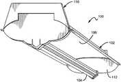
- FIG. 1is a perspective view of a lighting assembly 100 according to an embodiment of the present invention.
- the lighting assembly 100is particularly well-suited for use as a fixture for solid state light emitters, such as LEDs or vertical cavity surface emitting lasers (VCSELs), for example.
- solid state light emitterssuch as LEDs or vertical cavity surface emitting lasers (VCSELs)
- VCSELsvertical cavity surface emitting lasers
- a reflector 102is disposed proximate to an elongated heat sink 104 , both of which are described in detail herein.
- the reflector 102comprises a surface 106 that faces toward the heat sink 104 and a back surface 108 (shown in FIG. 2 ) on the opposite side.
- First and second end caps 110 , 112are arranged at both ends of the reflector 102 and the heat sink 104 to maintain the distance between the two elements and provide the structural support for the assembly 100 .
- the heat sink 104is exposed to the ambient environment.
- This structureis advantageous for several reasons. For example, air temperature in a typical residential or commercial room is much cooler than the air above the fixture (or the ceiling if the fixture is mounted above the ceiling plane). The air beneath the fixture is cooler because the room environment must be comfortable for occupants; whereas in the space above the fixture, cooler air temperatures are much less important. Additionally, room air is normally circulated, either by occupants moving through the room or by air conditioning. The movement of air throughout the room helps to break the boundary layer, facilitating thermal dissipation from the heat sink 104 .
- a room-side heat sink configurationprevents improper installation of insulation on top of the heat sink as is possible with typical solid state lighting applications in which the heat sink is disposed on the ceiling-side. This guard against improper installation can eliminate a potential fire hazard.
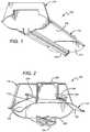
- FIG. 2is a perspective view of a cut-away portion of the lighting assembly 100 .
- the reflector 102 and heat sink 104are mounted to the inside surface of the first end cap 110 .
- these elementsare mounted using a snap-fit mechanism which provides reduced assembly time and cost.
- Other mounting meansmay also be used, such as pins, screws, adhesives, etc.
- the first end cap 110maintains the desired spacing between the reflector 102 and the heat sink 104 .
- the heat sink 104comprises a mount surface 202 on which light emitters (e.g., LEDs) can be mounted.
- the mount surface 202faces the surface 106 of the reflector 102 .
- the emitterscan be mounted such that they emit light toward the surface 106 , or a certain portion thereof. The emitted light is then reflected off the surface 106 and out into the ambient as useful light.
- the reflector 102can be constructed from many different materials.
- the reflector 102comprises a material which allows the reflector 102 to be extruded for efficient, cost-effective production.
- Some acceptable materialsinclude polycarbonates, such as Makrolon 6265X or FR6901 (commercially available from Bayer) or BFL4000 or BFL2000 (commercially available from Sabic). Many other materials may also be used to construct the reflector 102 .
- the reflector 102is easily scalable to accommodate lighting assemblies of varying length.
- the surface 106may be designed to have several different shapes to perform particular optical functions, such as color mixing and beam shaping, for example.
- Emitted lightmay be bounced off of one or more surfaces, including the surface 106 . This has the effect of disassociating the emitted light from its initial emission angle. Uniformity typically improves with an increasing number of bounces, but each bounce has an associated optical loss.
- an intermediate diffusion mechanisme.g., formed diffusers and textured lenses
- the surface 106should be highly reflective in the wavelength ranges of the light emitters. In some embodiments, the surface 106 may be 93% reflective or higher. In other embodiments it may be at least 95% reflective or at least 97% reflective.
- the surface 106may comprise many different materials. For many indoor lighting applications, it is desirable to present a uniform, soft light source without unpleasant glare, color striping, or hot spots.
- the surface 106may comprise a diffuse white reflector such as a microcellular polyethylene terephthalate (MCPET) material or a Dupont/WhiteOptics material, for example. Other white diffuse reflective materials can also be used.
- MPETmicrocellular polyethylene terephthalate
- Dupont/WhiteOptics materialfor example.
- Other white diffuse reflective materialscan also be used.
- Diffuse reflective coatingshave the inherent capability to mix light from solid state light sources having different spectra (i.e., different colors). These coatings are particularly well-suited for multi-source designs where two different spectra are mixed to produce a desired output color point. For example, LEDs emitting blue light may be used in combination with other sources of light, e.g., yellow light to yield a white light output.
- a diffuse reflective coatingmay eliminate the need for additional spatial color-mixing schemes that can introduce lossy elements into the system; although, in some embodiments it may be desirable to use a diffuse surface in combination with other diffusive elements.
- the surfacemay be coated with a phosphor material that converts the wavelength of at least some of the light from the light emitting diodes to achieve a light output of the desired color point.
- the surface 106By using a diffuse white reflective material for the surface 106 and by positioning the light sources to emit light first toward the surface 106 several design goals are achieved. For example, the surface 106 performs a color-mixing function, effectively doubling the mixing distance and greatly increasing the surface area of the source. Additionally, the surface luminance is modified from bright, uncomfortable point sources to a much larger, softer diffuse reflection. A diffuse white material also provides a uniform luminous appearance in the output. Harsh surface luminance gradients (max/min ratios of 10:1 or greater) that would typically require significant effort and heavy diffusers to ameliorate in a traditional direct view optic can be managed with much less aggressive (and lower light loss) diffusers achieving max/min ratios of 5:1, 3:1, or even 2:1.
- the surface 106can comprise materials other than diffuse reflectors.
- the surface 106can comprise a specular reflective material or a material that is partially diffuse reflective and partially specular reflective.
- a semi-specular materialmay be used on the center region with a diffuse material used in the side regions to give a more directional reflection to the sides. Many combinations are possible.
- the reflector back surface 108comprises elongated rails 204 that run longitudinally along the reflector 102 .
- the rails 204perform important dual functions. They provide a mechanism by which the assembly 100 can be mounted to an external surface, such as a ceiling. At the same time, the rails 204 also provide structural support, preventing longitudinal bending along the length of the assembly 100 which allows longer reflector components to be used.
- the rails 204may comprise features on the inner and outer surfaces, such as inner flanges 208 and outer flanges 210 .
- the flanges 208 , 210may interface with external elements, such as mounting structures, for example, and may take many different shapes depending on the design of the structures used for mounting.
- the rails 204may also comprise many other features necessary for mounting or other purposes.
- a U-shaped mount bracket 206is connected to the inner flange 208 .
- the outer flanges 210may be used for alternate mounting configurations discussed herein.
- the mounting bracket 206removably connects to the rails 204 using snap-fit or slide-fit mechanisms, for example.
- the mount bracket 206can be used to mount the light assembly 100 to a surface, such as a ceiling, when the assembly is mounted by suspension.
- the mounting bracket 206may be made of metal, plastic, or other materials that are strong enough to support the weight of the assembly 100 .
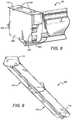
- FIG. 3is another perspective view of a portion of the lighting assembly 100 .
- the reflector 102is connected to the end cap 110 with a snap-fit interface 302 .
- the heat sink 104(not shown in FIG. 3 ) may also be connected to the end cap 110 with a snap-fit interface.
- the end cap 110may comprise access holes 304 to allow for an electrical conductor to be fed down from a ceiling, for example, if the assembly 100 is to be powered from an external source.
- the assembly 100may also be powered by a battery that can be stored inside the end cap 110 , eliminating the need for an external power source.
- the end cap 110can be constructed as two separate pieces 110 a , 110 b which can be joined using a snap-fit mechanism or screws, for example, so that the end cap can be disassembled for easy access to the electronics housed within.
- the end cap pieces 110 a , 110 bcan be joined using an adhesive, for example.
- the end cap 110may also comprise a removable side cover 306 to provide access to internal components.
- FIG. 3also shows an alternate mounting means for the assembly 100 .
- Hanging tongs 308may be used to suspend the assembly 100 from a ceiling.
- the assembly 100can be easily retrofit for installation in buildings that already have a mount system.
- the reflector rails 204are designed with inner and outer flanges 208 , 210 .
- Inner flanges 208are designed to interface with a mount mechanism such as mounting bracket 206 , for example.
- Outer flanges 210are designed to interface with a mount mechanism such as hanging tongs 308 , for example.
- the reflector 102can be designed to accommodate many different mounting structures and should not be limited to the exemplary embodiments shown herein.
- FIG. 4is another perspective view of a cut-away portion of the lighting assembly 100 .
- the mount bracket 206hooks on to the underside of the inner flange 208 as shown.
- the mount bracket 206may be connected to the inner flange 208 in many other ways as well.
- FIG. 5 ais a perspective view of a cross-sectional portion of a heat sink 500 that can be used in the lighting assembly 100 .
- the heat sink 500is shaped to define two parallel longitudinal conduits 502 that run along the entire length of the heat sink body 504 .
- the conduits 502are designed to accommodate wires, cords, cables or other electrical conductors for providing power to light emitters (not shown).
- the conduits 502should be large enough to carry the necessary power and signal cords.
- the heat sink 500comprises a flat mount surface 506 on which light emitters can be mounted. The emitters can be mounted directly to the mount surface 506 , or they can be disposed on a light strip which is then mounted to the mount surface 506 as discussed in more detail herein.
- FIG. 5 bis a cross-sectional view of the heat sink 500 .
- a light strip 508is shown disposed on the mount surface 506 .
- the light strip 506comprises one or more light emitters 510 mounted thereto.
- FIG. 6shows a perspective view of an end portion of the heat sink 500 .
- a cable 602is shown passing through one of the conduits 502 .
- the hollow heat sink structureprovides advantages over traditional heat sink designs. For example, the heat sink 500 requires less material to construct, reducing overall weight and cost.
- the heat sink 500also provides a wire way for the necessary power and signal cabling. This configuration eliminates the need for a separate wire way along the length of the assembly, which also reduces material and fabrication costs.
- the cable 602comprises a six-wire system that is used to power and control the light emitters.
- the cablecan comprise several types of connection adapters.
- This embodimentcomprises cylindrical cable connectors 604 for easy connection to another adjacent assembly in an end-to-end serial (i.e., daisy chain) configuration, as discussed in more detail herein. Many different cabling and connection schemes are possible.
- the heat sink 500can be constructed using many different thermally conductive materials.
- the heat sink 500may comprise an aluminum body 504 .
- the heat sink 500can be extruded for efficient, cost-effective production and convenient scalability.
- the heat sink mount surface 506provides a substantially flat area on which one or more light sources can be mounted. In some embodiments, the light sources will be pre-mounted on light strips.
- FIGS. 7 a - cshow a top plan view of portions of several light strips 700 , 720 , 740 that may be used to mount multiple LEDs to the mount surface 506 . Although LEDs are used as the light sources in various embodiments described herein, it is understood that other light sources, such as laser diodes for example, may be substituted in as the light sources in other embodiments of the present invention.
- the light assembly 100may comprise one or more emitters producing the same color of light or different colors of light.
- a multicolor sourceis used to produce white light.
- Several colored light combinationswill yield white light. For example, it is known in the art to combine light from a blue LED with wavelength-converted yellow (blue-shifted-yellow or “BSY”) light to yield white light with correlated color temperature (CCT) in the range between 5000K to 7000K (often designated as “cool white”).
- BSYwavelength-converted yellow
- CCTcorrelated color temperature
- Both blue and BSY lightcan be generated with a blue emitter by surrounding the emitter with phosphors that are optically responsive to the blue light.
- the phosphorsWhen excited, the phosphors emit yellow light which then combines with the blue light to make white. In this scheme, because the blue light is emitted in a narrow spectral range it is called saturated light. The BSY light is emitted in a much broader spectral range and, thus, is called unsaturated light.
- RGB schemesmay also be used to generate various colors of light.
- an amber emitteris added for an RGBA combination.
- the previous combinationsare exemplary; it is understood that many different color combinations may be used in embodiments of the present invention. Several of these possible color combinations are discussed in detail in U.S. Pat. No. 7,213,940 to Van de Ven et al.
- the lighting strips 700 , 720 , 740each represent possible LED combinations that result in an output spectrum that can be mixed to generate white light.
- Each lighting stripcan include the electronics and interconnections necessary to power the LEDs.
- the lighting stripcomprises a printed circuit board with the LEDs mounted and interconnected thereon.
- the lighting strip 700includes clusters 702 of discrete LEDs, with each LED within the cluster 702 spaced a distance from the next LED, and each cluster 702 spaced a distance from the next cluster 702 . If the LEDs within a cluster are spaced at too great distance from one another, the colors of the individual sources may become visible, causing unwanted color-striping. In some embodiments, an acceptable range of distances for separating consecutive LEDs within a cluster is not more than approximately 8 mm.
- the scheme shown in FIG. 7 auses a series of clusters 702 having two blue-shifted-yellow LEDs (“BSY”) and a single red LED (“R”). Once properly mixed the resultant output light will have a “warm white” appearance.
- BSYblue-shifted-yellow LEDs
- Rred LED
- the lighting strip 720includes clusters 722 of discrete LEDs.
- the scheme shown in FIG. 7 buses a series of clusters 722 having three BSY LEDs and a single red LED. This scheme will also yield a warm white output when sufficiently mixed.
- the lighting strip 740includes clusters 742 of discrete LEDs.
- the scheme shown in FIG. 7 cuses a series of clusters 742 having two BSY LEDs and two red LEDs. This scheme will also yield a warm white output when sufficiently mixed.
- FIGS. 7 a - cThe lighting schemes shown in FIGS. 7 a - c are meant to be exemplary. Thus, it is understood that many different LED combinations can be used in concert with known conversion techniques to generate a desired output light color.
- FIG. 8is a perspective view of the first end cap 110 of the lighting assembly 100 .
- the end cap 110is shown with the side cover 306 removed to expose electronics 802 which are mounted on a board 804 .
- the electronics 802are used to regulate the power to the light emitters and to control the brightness and color of the output light.
- the electronics 802can also perform many other functions.
- the removable side cover 306(not shown) provides access to the electronics 802 , allowing for full testing during and after assembly. Such testing may be easily implemented using Pogo pins, for example. Once testing is finished the side cover 306 can be replaced to protect the electronics 802 .
- the holes 304 on top of the end cap 110provide additional top-side access to the electronics for a connection to an external junction box, for example.
- the board 804is held place within the end cap 110 using tabs 806 , although other means such as screws or adhesive may also be used. Because the first end cap 110 houses the electronics necessary to power/control the light emitters, the second end cap 112 (not shown in FIG. 8 ) may not contain any electronic components, allowing for a thinner profile. However, in some embodiments the second end cap 112 may contain additional electronics, batteries, or other components.
- the end cap 110also includes space for the cable connectors 604 , allowing for the lighting assembly 100 to be easily connected to another similar assembly as shown herein with reference to FIG. 9 .
- FIG. 9shows a perspective view of a modular lighting assembly 900 according to an embodiment of the present invention.
- Individual light assemblies(such as assembly 100 ) can be connected in an end-to-end serial (i.e., daisy chain) configuration.
- Each assembly 100includes its own electronics 802 such that the individual assemblies 100 may be easily removed or added to the modular assembly 900 as needed.
- the assemblies 100include connectors, such as cable connector 604 that allow for the serial connection.
- the connections between the assemblies 100are made within the respective end caps 110 to protect the wired connections from outside elements.
- Respective first and second end capscan comprise snap-fit structures such that adjacent assemblies 100 may be easily connected, although other means may be used to connect adjacent assemblies.
- the second end capcomprises snap-fit structures on two opposing surfaces to facilitate connection of adjacent assemblies 100 .
- both the first and second end caps 110 , 112comprise snap-fit structures on two sides.
- the modular assembly 900comprises two individual assemblies 100 as shown.
- each assembly 100is approximately 8 ft long.
- the assemblies 100can easily be scaled to a desired length.
- other modular assembliescould comprise individual units having lengths of 2 ft, 4 ft, 6 ft, etc.
- individual units of different lengthscan be combined to construct a modular assembly having a particular size.
- a 2 ft unitcan be connected to an 8 ft unit to construct a 10 ft modular assembly. This is advantageous when designing modular assemblies for rooms having particular dimensions.
- the assembliescan have many different lengths. More than two of the assemblies can be connected to provide a longer series.
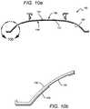
- FIG. 10 ais a cross-sectional view of another reflector that can be used in embodiments of the lighting assembly 100 .
- the reflector 150comprises two different materials having different optical and structural properties and different relative costs.
- the reflector 150comprises a surface 152 and a back surface 154 .
- the reflector 150comprises a first light-transmissive base material 156 (e.g., a polycarbonate) which provides the basic structure of the device.
- At least a portion of the surface 152comprises a second highly reflective material 158 .
- the two materials 156 , 158can be coextruded for more convenient and cost-efficient fabrication of the reflector 150 . For example, a cheaper bulk material may be used as the base material 152 , requiring a smaller amount of the more expensive reflective material 154 to manufacture the reflector 150 .
- the base material 156provides structural support to the reflector 150 and allows for transmission through areas of the surface 152 where the reflective material 158 is very thin or non-existent.
- the reflector 150comprises transmissive windows 160 where little to no reflective material is disposed.
- FIG. 10 bis a close-up view of a portion of the reflector 150 showing one such window. These windows 160 allow light to pass through them, providing uplight (i.e., light emitted from the back surface 154 of the reflector 150 ).
- the amount of uplight generated by the reflector 150can be varied by regulating the thickness of reflective material 158 and/or the size and frequency of the windows 160 across the surface 152 . Desired transmissive and reflective effects may be achieved using a non-uniform distribution of the reflective material 158 across the surface 152 .
Landscapes
- Engineering & Computer Science (AREA)
- General Engineering & Computer Science (AREA)
- Microelectronics & Electronic Packaging (AREA)
- Non-Portable Lighting Devices Or Systems Thereof (AREA)
- Arrangement Of Elements, Cooling, Sealing, Or The Like Of Lighting Devices (AREA)
Abstract
Description
Claims (42)
Priority Applications (6)
| Application Number | Priority Date | Filing Date | Title |
|---|---|---|---|
| US13/189,535US10823347B2 (en) | 2011-07-24 | 2011-07-24 | Modular indirect suspended/ceiling mount fixture |
| PCT/US2012/047084WO2013016079A2 (en) | 2011-07-24 | 2012-07-17 | Modular indirect suspended/ceiling mount fixture |
| CN201280036914.2ACN103703303A (en) | 2011-07-24 | 2012-07-17 | Modular indirect suspended/ceiling mount fixture |
| MX2014000980AMX2014000980A (en) | 2011-07-24 | 2012-07-17 | Modular indirect suspended/ceiling mount fixture. |
| EP12743003.1AEP2734774B1 (en) | 2011-07-24 | 2012-07-17 | Modular indirect suspended/ceiling mount fixture |
| US17/032,252US11209135B2 (en) | 2011-07-24 | 2020-09-25 | Modular indirect suspended/ceiling mount fixture |
Applications Claiming Priority (1)
| Application Number | Priority Date | Filing Date | Title |
|---|---|---|---|
| US13/189,535US10823347B2 (en) | 2011-07-24 | 2011-07-24 | Modular indirect suspended/ceiling mount fixture |
Related Child Applications (1)
| Application Number | Title | Priority Date | Filing Date |
|---|---|---|---|
| US17/032,252ContinuationUS11209135B2 (en) | 2011-07-24 | 2020-09-25 | Modular indirect suspended/ceiling mount fixture |
Publications (2)
| Publication Number | Publication Date |
|---|---|
| US20130021792A1 US20130021792A1 (en) | 2013-01-24 |
| US10823347B2true US10823347B2 (en) | 2020-11-03 |
Family
ID=46604064
Family Applications (2)
| Application Number | Title | Priority Date | Filing Date |
|---|---|---|---|
| US13/189,535Active2032-09-15US10823347B2 (en) | 2011-07-24 | 2011-07-24 | Modular indirect suspended/ceiling mount fixture |
| US17/032,252ActiveUS11209135B2 (en) | 2011-07-24 | 2020-09-25 | Modular indirect suspended/ceiling mount fixture |
Family Applications After (1)
| Application Number | Title | Priority Date | Filing Date |
|---|---|---|---|
| US17/032,252ActiveUS11209135B2 (en) | 2011-07-24 | 2020-09-25 | Modular indirect suspended/ceiling mount fixture |
Country Status (5)
| Country | Link |
|---|---|
| US (2) | US10823347B2 (en) |
| EP (1) | EP2734774B1 (en) |
| CN (1) | CN103703303A (en) |
| MX (1) | MX2014000980A (en) |
| WO (1) | WO2013016079A2 (en) |
Cited By (4)
| Publication number | Priority date | Publication date | Assignee | Title |
|---|---|---|---|---|
| US11015771B2 (en)* | 2018-02-13 | 2021-05-25 | Fujian Sanan Sino-Science Photobiotech Co., Ltd. | LED plant illumination lamp module |
| US11585515B2 (en) | 2016-01-28 | 2023-02-21 | Korrus, Inc. | Lighting controller for emulating progression of ambient sunlight |
| US11635188B2 (en)* | 2017-03-27 | 2023-04-25 | Korrus, Inc. | Lighting systems generating visible-light emissions for dynamically emulating sky colors |
| US12385623B2 (en) | 2016-01-28 | 2025-08-12 | Korrus, Inc. | Beam-shaping lighting systems |
Families Citing this family (85)
| Publication number | Priority date | Publication date | Assignee | Title |
|---|---|---|---|---|
| US20080029720A1 (en) | 2006-08-03 | 2008-02-07 | Intematix Corporation | LED lighting arrangement including light emitting phosphor |
| US8864340B2 (en) | 2009-10-05 | 2014-10-21 | Lighting Science Group Corporation | Low profile light having concave reflector and associated methods |
| US9581756B2 (en) | 2009-10-05 | 2017-02-28 | Lighting Science Group Corporation | Light guide for low profile luminaire |
| US9028091B2 (en) | 2009-10-05 | 2015-05-12 | Lighting Science Group Corporation | Low profile light having elongated reflector and associated methods |
| US9157581B2 (en) | 2009-10-05 | 2015-10-13 | Lighting Science Group Corporation | Low profile luminaire with light guide and associated systems and methods |
| US9827439B2 (en) | 2010-07-23 | 2017-11-28 | Biological Illumination, Llc | System for dynamically adjusting circadian rhythm responsive to scheduled events and associated methods |
| US8841864B2 (en) | 2011-12-05 | 2014-09-23 | Biological Illumination, Llc | Tunable LED lamp for producing biologically-adjusted light |
| US9532423B2 (en) | 2010-07-23 | 2016-12-27 | Lighting Science Group Corporation | System and methods for operating a lighting device |
| US8686641B2 (en) | 2011-12-05 | 2014-04-01 | Biological Illumination, Llc | Tunable LED lamp for producing biologically-adjusted light |
| US8760370B2 (en) | 2011-05-15 | 2014-06-24 | Lighting Science Group Corporation | System for generating non-homogenous light and associated methods |
| US9024536B2 (en) | 2011-12-05 | 2015-05-05 | Biological Illumination, Llc | Tunable LED lamp for producing biologically-adjusted light and associated methods |
| US8465167B2 (en) | 2011-09-16 | 2013-06-18 | Lighting Science Group Corporation | Color conversion occlusion and associated methods |
| US9546765B2 (en) | 2010-10-05 | 2017-01-17 | Intematix Corporation | Diffuser component having scattering particles |
| US9360202B2 (en) | 2011-05-13 | 2016-06-07 | Lighting Science Group Corporation | System for actively cooling an LED filament and associated methods |
| US9151482B2 (en) | 2011-05-13 | 2015-10-06 | Lighting Science Group Corporation | Sealed electrical device with cooling system |
| TW201314105A (en)* | 2011-09-29 | 2013-04-01 | Foxsemicon Integrated Tech Inc | LED lamp |
| EP2581652B1 (en)* | 2011-10-12 | 2017-07-19 | Thorn Lighting Limited | Mounting arrangement |
| US8963450B2 (en) | 2011-12-05 | 2015-02-24 | Biological Illumination, Llc | Adaptable biologically-adjusted indirect lighting device and associated methods |
| US9220202B2 (en) | 2011-12-05 | 2015-12-29 | Biological Illumination, Llc | Lighting system to control the circadian rhythm of agricultural products and associated methods |
| US9913341B2 (en) | 2011-12-05 | 2018-03-06 | Biological Illumination, Llc | LED lamp for producing biologically-adjusted light including a cyan LED |
| US9289574B2 (en) | 2011-12-05 | 2016-03-22 | Biological Illumination, Llc | Three-channel tuned LED lamp for producing biologically-adjusted light |
| US9261263B2 (en) | 2012-04-23 | 2016-02-16 | Tempo Industries, Llc | Commercial lighting integrated platform |
| US9335041B2 (en) | 2012-05-07 | 2016-05-10 | Abl Ip Holding Llc | LED light fixture |
| AU346826S (en)* | 2012-08-13 | 2013-02-08 | Waldmann Herbert Gmbh & Co Kg | A lamp |
| US9127818B2 (en) | 2012-10-03 | 2015-09-08 | Lighting Science Group Corporation | Elongated LED luminaire and associated methods |
| US20140185269A1 (en) | 2012-12-28 | 2014-07-03 | Intermatix Corporation | Solid-state lamps utilizing photoluminescence wavelength conversion components |
| DE102013201203A1 (en)* | 2013-01-25 | 2014-07-31 | Zumtobel Lighting Gmbh | Lighting system |
| US9347655B2 (en) | 2013-03-11 | 2016-05-24 | Lighting Science Group Corporation | Rotatable lighting device |
| US9459397B2 (en) | 2013-03-12 | 2016-10-04 | Lighting Science Group Corporation | Edge lit lighting device |
| USD731103S1 (en)* | 2013-03-14 | 2015-06-02 | Albeo Technologies, Inc. | Combined LED light fixture and set of glare shields |
| USD730558S1 (en)* | 2013-03-14 | 2015-05-26 | Cree, Inc. | Linear full wrap light fixture |
| USD733347S1 (en)* | 2013-03-14 | 2015-06-30 | Cree, Inc. | Linear indirect asymmetric light fixture |
| USD738026S1 (en)* | 2013-03-14 | 2015-09-01 | Cree, Inc. | Linear wrap light fixture |
| US9110209B2 (en)* | 2013-03-15 | 2015-08-18 | Cooper Technologies Company | Edgelit LED blade fixture |
| USD733952S1 (en)* | 2013-03-15 | 2015-07-07 | Cree, Inc. | Indirect linear fixture |
| WO2014151263A1 (en) | 2013-03-15 | 2014-09-25 | Intematix Corporation | Photoluminescence wavelength conversion components |
| US9429283B2 (en) | 2013-04-15 | 2016-08-30 | Tempo Industries, Llc | Adjustable length articulated LED light fixtures |
| USD743610S1 (en)* | 2013-04-26 | 2015-11-17 | Solamagic Gmbh | Lamp |
| US9719636B2 (en) | 2013-08-07 | 2017-08-01 | Florida Intellectual Properties Llc | LED lighting device |
| US9453639B2 (en)* | 2013-09-24 | 2016-09-27 | Mandy Holdings Lllp | Rectilinear light source for elevator interior |
| US9093004B2 (en) | 2013-10-02 | 2015-07-28 | Tempo Industries, Llc | Seat marker assembly |
| USD739359S1 (en) | 2013-10-11 | 2015-09-22 | Cree, Inc. | Lighting control device |
| US9622321B2 (en) | 2013-10-11 | 2017-04-11 | Cree, Inc. | Systems, devices and methods for controlling one or more lights |
| US9080731B2 (en)* | 2013-11-04 | 2015-07-14 | Luminator Holding, Lp | Lighting housing with LED illumination insert |
| US9429294B2 (en) | 2013-11-11 | 2016-08-30 | Lighting Science Group Corporation | System for directional control of light and associated methods |
| US20150252965A1 (en)* | 2014-03-07 | 2015-09-10 | Intematix Corporation | Solid-state linear lighting arrangements including light emitting phosphor |
| USD738030S1 (en)* | 2014-03-17 | 2015-09-01 | GE Lighting Solutions, LLC | Light fixture |
| USD752803S1 (en) | 2014-05-15 | 2016-03-29 | Jaime A. Reyes | Light fixture |
| USD728848S1 (en)* | 2014-05-15 | 2015-05-05 | Jaime A. Reyes | Lighting diffuser |
| US9596740B2 (en) | 2014-07-14 | 2017-03-14 | Tempo Industries, Llc | LED auditorium house light system |
| CN104061500A (en)* | 2014-07-16 | 2014-09-24 | 常州工学院 | LED spotlight capable of emitting highly-even light beams |
| DE102014114309A1 (en)* | 2014-10-01 | 2016-04-07 | Osram Gmbh | Luminaire with direct and indirect light |
| JP6489863B2 (en)* | 2015-02-20 | 2019-03-27 | 三菱電機株式会社 | Lighting device, lighting fixture, and light source unit |
| JP6528235B2 (en)* | 2015-03-19 | 2019-06-12 | 株式会社ホタルクス | LED light source unit, body unit, and LED lighting apparatus |
| US9458995B1 (en) | 2015-04-10 | 2016-10-04 | Tempo Industries, Llc | Wiring rail platform based LED light fixtures |
| USD792000S1 (en)* | 2015-04-29 | 2017-07-11 | Chad Burroughs | Lighting apparatus |
| US9943042B2 (en) | 2015-05-18 | 2018-04-17 | Biological Innovation & Optimization Systems, LLC | Grow light embodying power delivery and data communications features |
| CA2987062C (en) | 2015-06-04 | 2023-08-15 | Cooper Technologies Company | Linear led luminaire for use in harsh and hazardous locations |
| US10584831B2 (en) | 2015-06-04 | 2020-03-10 | Eaton Intelligent Power Limited | Luminaire for use in harsh and hazardous locations |
| USD786476S1 (en)* | 2015-08-21 | 2017-05-09 | Abl Ip Holding Llc | Light fixture |
| US9844116B2 (en) | 2015-09-15 | 2017-12-12 | Biological Innovation & Optimization Systems, LLC | Systems and methods for controlling the spectral content of LED lighting devices |
| US9788387B2 (en) | 2015-09-15 | 2017-10-10 | Biological Innovation & Optimization Systems, LLC | Systems and methods for controlling the spectral content of LED lighting devices |
| US9784441B2 (en) | 2015-11-13 | 2017-10-10 | Tempo Industries, Llc | Compact A.C. powered LED light fixture |
| DE102015226670A1 (en)* | 2015-12-23 | 2017-06-29 | Osram Gmbh | LIGHTING DEVICE |
| CN112963745B (en)* | 2016-02-15 | 2023-09-29 | 莫列斯有限公司 | Lighting device |
| CA170038S (en)* | 2016-03-02 | 2017-03-23 | Dyson Technology Ltd | Lighting fixture |
| CA170043S (en)* | 2016-03-02 | 2017-03-23 | Dyson Technology Ltd | Lighting fixture |
| CA170044S (en)* | 2016-03-02 | 2017-03-23 | Dyson Technology Ltd | Lighting fixture |
| US9964289B2 (en) | 2016-03-25 | 2018-05-08 | Tempo Industries, Llc | LED light fixtures having plug-together light fixture modules |
| US9841153B2 (en) | 2016-04-09 | 2017-12-12 | Tempo Industries, Llc | Adaptive LED cove lighting system |
| US10352509B2 (en) | 2016-04-09 | 2019-07-16 | Tempo Industries, Llc | Adaptive LED cove lighting system with micro baffle |
| US10151435B2 (en) | 2016-04-09 | 2018-12-11 | Tempo Industries, Llc | Adaptive LED cove lighting system |
| US10222012B2 (en) | 2016-08-08 | 2019-03-05 | Tempo Industries, Llc | Ceiling-based LED auditorium pathway lighting apparatus |
| US10595376B2 (en) | 2016-09-13 | 2020-03-17 | Biological Innovation & Optimization Systems, LLC | Systems and methods for controlling the spectral content of LED lighting devices |
| AU2018215192A1 (en)* | 2017-01-31 | 2019-08-22 | Scott David Moore | Mounting device and packaging system for lighting product |
| US10113721B1 (en)* | 2017-11-09 | 2018-10-30 | Ruei-Hsing Lin | LED Lamp |
| US20190230868A1 (en)* | 2018-01-29 | 2019-08-01 | Carson Technology Co., Ltd. | Grow lighting system |
| US10451264B2 (en) | 2018-03-20 | 2019-10-22 | Tempo Industries, Llc | Water resistant LED light fixtures |
| US20190346089A1 (en)* | 2018-05-08 | 2019-11-14 | Elite Lighting | Light Fixture |
| US20200022313A1 (en)* | 2018-07-19 | 2020-01-23 | Just Greens Llc | Fixtureless Lamp |
| US10721806B1 (en) | 2019-03-29 | 2020-07-21 | Tempo Industries, Llc | Auditorium house light positioning system |
| US10823367B1 (en)* | 2019-04-26 | 2020-11-03 | Insight Lighting, Inc. | Modular LED light fixture with spaced diffuser |
| CN113874652B (en)* | 2019-06-03 | 2024-08-27 | 昕诺飞控股有限公司 | Lamp, suspension device and method for respectively suspending and detaching lamp |
| WO2021151728A1 (en)* | 2020-01-27 | 2021-08-05 | Signify Holding B.V. | Linear modular luminaire |
| JP2023546467A (en) | 2020-10-23 | 2023-11-02 | シグニファイ ホールディング ビー ヴィ | Lighting device with uplighting including adjustable optics |
Citations (218)
| Publication number | Priority date | Publication date | Assignee | Title |
|---|---|---|---|---|
| US2356654A (en) | 1944-08-22 | Catadioptric lens | ||
| GB774198A (en) | 1954-07-08 | 1957-05-08 | F W Thorpe Ltd | Improvements relating to fluorescent electric lighting installations |
| US3381124A (en) | 1966-10-12 | 1968-04-30 | Solar Light Mfg Co | Louver grid for lighting fixture |
| US3743826A (en) | 1970-11-12 | 1973-07-03 | Emerson Electric Co | Ceiling modules |
| US3790774A (en) | 1972-06-23 | 1974-02-05 | Sunbeam Lighting Co | Fluorescent luminaire |
| US4939627A (en)* | 1988-10-20 | 1990-07-03 | Peerless Lighting Corporation | Indirect luminaire having a secondary source induced low brightness lens element |
| US5025356A (en)* | 1988-10-07 | 1991-06-18 | Get Sylvania Canada Ltd | Small profile high wattage horitcultural luminaire |
| US5526190A (en) | 1994-09-29 | 1996-06-11 | Xerox Corporation | Optical element and device for providing uniform irradiance of a surface |
| JPH1069809A (en) | 1996-08-27 | 1998-03-10 | Matsushita Electric Works Ltd | Luminaire |
| US5823663A (en) | 1996-10-21 | 1998-10-20 | National Service Industries, Inc. | Fluorescent troffer lighting fixture |
| USD407473S (en) | 1995-10-02 | 1999-03-30 | Wimbock Besitz Gmbh | Combined ventilating and lighting unit for a kitchen ceiling |
| US6079851A (en) | 1997-02-26 | 2000-06-27 | The Whitaker Corporation | Fluorescent lighting fixture having two separate end supports, separate integral ballast subassembly and lamps sockets, and hood positionable above end supports for mounting in or below opening in suspended ceiling |
| US6102550A (en) | 1999-02-16 | 2000-08-15 | Photronix, Llc | Bracket assembly for fluorescent lighting fixture having removable, high-frequency power output ballast |
| US6149283A (en) | 1998-12-09 | 2000-11-21 | Rensselaer Polytechnic Institute (Rpi) | LED lamp with reflector and multicolor adjuster |
| US6155699A (en) | 1999-03-15 | 2000-12-05 | Agilent Technologies, Inc. | Efficient phosphor-conversion led structure |
| US6210025B1 (en) | 1999-07-21 | 2001-04-03 | Nsi Enterprises, Inc. | Lensed troffer lighting fixture |
| US6234643B1 (en) | 1999-09-01 | 2001-05-22 | Joseph F. Lichon, Jr. | Lay-in/recessed lighting fixture having direct/indirect reflectors |
| US6402347B1 (en) | 1998-12-17 | 2002-06-11 | Koninklijke Philips Electronics N.V. | Light generator for introducing light into a bundle of optical fibers |
| JP2002244027A (en) | 2000-12-15 | 2002-08-28 | Olympus Optical Co Ltd | Range-finding device |
| US6443598B1 (en) | 1999-04-17 | 2002-09-03 | Luxonic Lighting Plc | Lighting appliance with glare reducing cross blades |
| US6523974B2 (en) | 2000-03-20 | 2003-02-25 | Hartmut S. Engel | Lamp cover |
| EP1298383A2 (en) | 2001-09-28 | 2003-04-02 | Osram Sylvania Inc. | Replaceable led lamp capsule |
| US6578979B2 (en) | 2000-09-26 | 2003-06-17 | Lisa Lux Gmbh | Illumination body for refrigeration devices |
| US6598998B2 (en) | 2001-05-04 | 2003-07-29 | Lumileds Lighting, U.S., Llc | Side emitting light emitting device |
| EP1357335A2 (en) | 2002-04-23 | 2003-10-29 | Nichia Corporation | Lighting apparatus |
| WO2003102467A2 (en) | 2002-06-03 | 2003-12-11 | Everbrite, Inc. | Led accent lighting units |
| US20040001344A1 (en)* | 2002-07-01 | 2004-01-01 | Accu-Sort Systems, Inc. | Integrating led illumination system for machine vision systems |
| JP3097327U (en) | 2003-04-22 | 2004-01-22 | 三和企業股▲ふん▼有限公司 | Direct-type backlight module assembly structure |
| US20040085779A1 (en) | 2002-10-01 | 2004-05-06 | Pond Gregory R. | Light emitting diode headlamp and headlamp assembly |
| JP2004140327A (en) | 2002-08-21 | 2004-05-13 | Nippon Leiz Co Ltd | Light source, light guide, and planar light-emitting device |
| US20040100796A1 (en) | 2002-11-21 | 2004-05-27 | Matthew Ward | Light emitting diode (LED) picture element |
| USD496121S1 (en) | 2004-02-03 | 2004-09-14 | Ledalite Architectural Products | Recessed fluorescent luminaire |
| US20040240230A1 (en) | 2003-05-30 | 2004-12-02 | Shigemasa Kitajima | Light-emitting unit |
| JP2004345615A (en) | 2003-05-19 | 2004-12-09 | Shigeru Komori | Flashing type coloring head lamp for motorcycle |
| US6871983B2 (en)* | 2001-10-25 | 2005-03-29 | Tir Systems Ltd. | Solid state continuous sealed clean room light fixture |
| TW200524186A (en) | 2003-12-05 | 2005-07-16 | Mitsubishi Electric Corp | Light emitting device and lighting apparatus using the same |
| US20050180135A1 (en) | 2004-02-18 | 2005-08-18 | Gelcore Llc | Lighting apparatus for creating a substantially homogenous lit appearance |
| US6948838B2 (en) | 2002-01-15 | 2005-09-27 | Fer Fahrzeugelektrik Gmbh | Vehicle lamp having prismatic element |
| US6948840B2 (en) | 2001-11-16 | 2005-09-27 | Everbrite, Llc | Light emitting diode light bar |
| US6951415B2 (en) | 2002-07-04 | 2005-10-04 | Koito Manufacturing Co., Ltd. | Vehicle lamp |
| US20050264716A1 (en) | 2004-05-28 | 2005-12-01 | Samsung Electro-Mechanics Co., Ltd. | LED package and backlight assembly for LCD comprising the same |
| US20050281023A1 (en) | 2004-06-18 | 2005-12-22 | Gould Carl T | Light fixture and lens assembly for same |
| US7021797B2 (en) | 2003-05-13 | 2006-04-04 | Light Prescriptions Innovators, Llc | Optical device for repositioning and redistributing an LED's light |
| EP1653254A2 (en) | 2004-10-18 | 2006-05-03 | Samsung Electronics Co., Ltd. | Light emitting diode and lens for the same |
| US7049761B2 (en) | 2000-02-11 | 2006-05-23 | Altair Engineering, Inc. | Light tube and power supply circuit |
| JP2006173624A (en) | 2004-12-15 | 2006-06-29 | Shogen Koden Kofun Yugenkoshi | LED light source |
| US7111969B2 (en) | 2002-10-22 | 2006-09-26 | Schefenacker Vision Systems Germany Gmbh | Vehicle lamp |
| US20060221611A1 (en) | 2005-04-04 | 2006-10-05 | Samsung Electronics Co., Ltd. | Back light unit and liquid crystal display employing the same |
| US20060245208A1 (en) | 2005-04-27 | 2006-11-02 | Mitsubishi Denki Kabushiki Kaisha | Planar light-source device |
| US20060262521A1 (en)* | 2005-05-23 | 2006-11-23 | Color Kinetics Incorporated | Methods and apparatus for providing lighting via a grid system of a suspended ceiling |
| US20060279671A1 (en) | 2005-05-31 | 2006-12-14 | Lg.Philips Lcd Co., Ltd. | Backlight assembly for liquid crystal display device and liquid crystal display device using the same |
| EP1737051A1 (en) | 2005-06-24 | 2006-12-27 | L.G. Philips LCD Co., Ltd. | Backlight assembly including light emitting diode and display device including the same |
| US20060291206A1 (en) | 2003-01-24 | 2006-12-28 | Marco Angelini | Multiple optical assembly for a led lighting device, and red lighting device comprising such an optical assembly |
| US7175296B2 (en) | 2005-06-21 | 2007-02-13 | Eastman Kodak Company | Removable flat-panel lamp and fixture |
| CN1934389A (en) | 2004-03-03 | 2007-03-21 | 约翰逊父子公司 | LED bulbs that emit active ingredients |
| US20070070625A1 (en) | 2005-09-23 | 2007-03-29 | Lg.Philips Lcd Co., Ltd. | Backlight assembly and liquid crystal display module using the same |
| US7213940B1 (en) | 2005-12-21 | 2007-05-08 | Led Lighting Fixtures, Inc. | Lighting device and lighting method |
| US7217004B2 (en) | 2004-05-03 | 2007-05-15 | Samsung Electro-Mechanics Co., Ltd. | Light emitting diode array module for providing backlight and backlight unit having the same |
| CN1963289A (en) | 2005-11-11 | 2007-05-16 | 株式会社日立显示器 | Illuminating device and liquid-crystal display device using the same |
| US7237924B2 (en) | 2003-06-13 | 2007-07-03 | Lumination Llc | LED signal lamp |
| US20070211457A1 (en) | 2004-06-18 | 2007-09-13 | Mayfield John T Iii | Replacement light fixture and lens assembly for same |
| EP1847762A2 (en) | 2006-04-19 | 2007-10-24 | FARO FABBRICA APPARECCHIATURE RAZIONALI ODONTOIATRICHE S.p.A. | Compact lighting device, in particular for use in a dental lamp |
| US20070253205A1 (en) | 2005-01-08 | 2007-11-01 | Welker Mark L | Fixture |
| USD556358S1 (en) | 2005-11-22 | 2007-11-27 | Ledalite Architectural Products | Recessed fluorescent luminaire |
| EP1860467A1 (en) | 2006-05-24 | 2007-11-28 | Industrial Technology Research Institute | Lens and light emitting diode using the lens to achieve homogeneous illumination |
| US20070279910A1 (en) | 2006-06-02 | 2007-12-06 | Gigno Technology Co., Ltd. | Illumination device |
| US20070297181A1 (en) | 2006-06-22 | 2007-12-27 | John Thomas Mayfield | Louver assembly for a light fixture |
| US20080019147A1 (en) | 2006-07-20 | 2008-01-24 | Luminus Devices, Inc. | LED color management and display systems |
| US20080037284A1 (en) | 2006-04-21 | 2008-02-14 | Rudisill Charles A | Lightguide tile modules and modular lighting system |
| US20080049422A1 (en)* | 2006-08-22 | 2008-02-28 | Automatic Power, Inc. | LED lantern assembly |
| US7338182B1 (en)* | 2004-09-13 | 2008-03-04 | Oldenburg Group Incorporated | Lighting fixture housing for suspended ceilings and method of installing same |
| US7341358B2 (en) | 2004-09-24 | 2008-03-11 | Epistar Corporation | Illumination apparatus |
| CN101188261A (en) | 2007-12-17 | 2008-05-28 | 天津理工大学 | Light-emitting diodes and surface light sources with large divergence angles |
| JP2008147044A (en) | 2006-12-11 | 2008-06-26 | Ushio Spex Inc | Adapter of unit type downlight |
| US20080232093A1 (en) | 2007-03-22 | 2008-09-25 | Led Folio Corporation | Seamless lighting assembly |
| US20080278943A1 (en) | 2005-11-11 | 2008-11-13 | Koninklijke Philips Electronics, N.V. | Luminaire Comprising Leds |
| US20080303977A1 (en) | 2007-06-11 | 2008-12-11 | Hitachi Displays, Ltd. | Liquid Crystal Display Device |
| DE102007030186A1 (en) | 2007-06-27 | 2009-01-02 | Harald Hofmann | Linear LED lamp |
| US20090034247A1 (en) | 2007-07-31 | 2009-02-05 | Boyer John D | Lighting apparatus |
| WO2009030233A1 (en) | 2007-09-05 | 2009-03-12 | Martin Professional A/S | Led bar |
| US20090073693A1 (en) | 2007-09-17 | 2009-03-19 | Nall Jeffrey M | Led lighting system for a cabinet sign |
| TW200914759A (en) | 2007-05-24 | 2009-04-01 | Koninkl Philips Electronics Nv | Color-tunable illumination system |
| USD593246S1 (en) | 2008-08-29 | 2009-05-26 | Hubbell Incorporated | Full distribution troffer luminaire |
| US20090161356A1 (en) | 2007-05-30 | 2009-06-25 | Cree Led Lighting Solutions, Inc. | Lighting device and method of lighting |
| JP3151501U (en) | 2008-12-22 | 2009-06-25 | 馨意科技股▲分▼有限公司 | Structure of light-emitting diode lamp tube |
| US20090168439A1 (en) | 2007-12-31 | 2009-07-02 | Wen-Chiang Chiang | Ceiling light fixture adaptable to various lamp assemblies |
| US7559672B1 (en) | 2007-06-01 | 2009-07-14 | Inteled Corporation | Linear illumination lens with Fresnel facets |
| US20090196024A1 (en) | 2008-01-31 | 2009-08-06 | Kenall Manufacturing Co. | Ceiling-Mounted Troffer-Type Light Fixture |
| US20090237958A1 (en) | 2008-03-21 | 2009-09-24 | Led Folio Corporation | Low-clearance light-emitting diode lighting |
| US7594736B1 (en) | 2007-10-22 | 2009-09-29 | Kassay Charles E | Fluorescent lighting fixtures with light transmissive windows aimed to provide controlled illumination above the mounted lighting fixture |
| US20090262543A1 (en) | 2008-04-18 | 2009-10-22 | Genius Electronic Optical Co., Ltd. | Light base structure of high-power LED street lamp |
| US7614767B2 (en) | 2006-06-09 | 2009-11-10 | Abl Ip Holding Llc | Networked architectural lighting with customizable color accents |
| US7618157B1 (en)* | 2008-06-25 | 2009-11-17 | Osram Sylvania Inc. | Tubular blue LED lamp with remote phosphor |
| US7618160B2 (en) | 2007-05-23 | 2009-11-17 | Visteon Global Technologies, Inc. | Near field lens |
| WO2009140761A1 (en) | 2008-05-23 | 2009-11-26 | Light Engine Limited | Non-glare reflective led lighting apparatus with heat sink mounting |
| US20090296388A1 (en) | 2008-06-02 | 2009-12-03 | Advanced Optoelectronic Technology Inc. | Led lighting module |
| US20090310354A1 (en) | 2005-09-15 | 2009-12-17 | Zampini Ii Thomas L | Interconnection arrangement having mortise and tenon connection features |
| WO2009157999A1 (en) | 2008-06-25 | 2009-12-30 | Cree, Inc. | Solid state lighting devices including light mixtures |
| USD608932S1 (en) | 2009-04-17 | 2010-01-26 | Michael Castelli | Light fixture |
| US7654688B2 (en) | 2007-12-14 | 2010-02-02 | Fu Zhun Precision Industry (Shen Zhen) Co., Ltd. | LED lamp with an improved heat sink |
| US7654702B1 (en) | 2008-08-25 | 2010-02-02 | Fu Zhun Precision (Shen Zhen) Co., Ltd. | LED lamp |
| US20100039579A1 (en) | 2008-08-12 | 2010-02-18 | Samsung Electronics Co., Ltd. | Liquid crystal display with light emitting diode backlight assembly and liquid crystal display thereof |
| USD611183S1 (en) | 2009-07-10 | 2010-03-02 | Picasso Lighting Industries LLC | Lighting fixture |
| WO2010024583A2 (en) | 2008-08-26 | 2010-03-04 | 주식회사 솔라코 컴퍼니 | Led lighting device |
| US7674005B2 (en)* | 2004-07-29 | 2010-03-09 | Focal Point, Llc | Recessed sealed lighting fixture |
| US20100061108A1 (en) | 2007-10-10 | 2010-03-11 | Cordelia Lighting, Inc. | Lighting fixture with recessed baffle trim unit |
| WO2010042216A2 (en) | 2008-10-10 | 2010-04-15 | Digital Optics International, Llc | Distributed illumination system |
| US20100097794A1 (en) | 2007-12-11 | 2010-04-22 | Prodisc Technology Inc. | LED lamp structure for reducing multiple shadows |
| US20100103678A1 (en) | 2008-10-24 | 2010-04-29 | Cree Led Lighting Solutions, Inc. | Lighting device, heat transfer structure and heat transfer element |
| US20100110679A1 (en) | 2008-11-04 | 2010-05-06 | Advanced Optoelectronic Technology Inc. | Light emitting diode light module and optical engine thereof |
| JP2010103687A (en) | 2008-10-22 | 2010-05-06 | Sanyo Electric Co Ltd | Linear illuminating device and image reader |
| US7712918B2 (en) | 2007-12-21 | 2010-05-11 | Altair Engineering , Inc. | Light distribution using a light emitting diode assembly |
| US7722227B2 (en) | 2007-10-10 | 2010-05-25 | Cordelia Lighting, Inc. | Lighting fixture with recessed baffle trim unit |
| US7722220B2 (en)* | 2006-05-05 | 2010-05-25 | Cree Led Lighting Solutions, Inc. | Lighting device |
| US20100142202A1 (en) | 2008-12-05 | 2010-06-10 | Toshiba Lighting & Technology Corporation | Luminaire |
| US20100172133A1 (en) | 2009-01-06 | 2010-07-08 | Foxconn Technology Co., Ltd. | Led illumination device and lamp unit thereof |
| DE202010001832U1 (en) | 2009-12-31 | 2010-07-08 | UNISTAR OPTO CORPORATION, Neihu | Tubeless, light-emitting diode-based lighting device |
| CN101776254A (en) | 2009-01-10 | 2010-07-14 | 富准精密工业(深圳)有限公司 | Light emitting diode lamp and photo engine thereof |
| US20100177532A1 (en)* | 2009-01-15 | 2010-07-15 | Altair Engineering, Inc. | Led lens |
| CN101790660A (en) | 2007-05-07 | 2010-07-28 | 科锐Led照明科技公司 | Lamp and lighting device |
| US20100188609A1 (en) | 2008-08-07 | 2010-07-29 | Panasonic Corporation | Illuminating lens, and lighting device, surface light source, and liquid-crystal display apparatus each using the same |
| US7768192B2 (en) | 2005-12-21 | 2010-08-03 | Cree Led Lighting Solutions, Inc. | Lighting device and lighting method |
| US20100253591A1 (en) | 2009-04-03 | 2010-10-07 | Au Optronics Corporation | Display device and multi-display apparatus |
| US20100254146A1 (en) | 2009-04-02 | 2010-10-07 | Mccanless Forrest S | Light fixture having selectively positionabe housing |
| US20100254128A1 (en) | 2009-04-06 | 2010-10-07 | Cree Led Lighting Solutions, Inc. | Reflector system for lighting device |
| US20100254145A1 (en) | 2009-04-03 | 2010-10-07 | Panasonic Corporation | Lighting device |
| US7815338B2 (en) | 2008-03-02 | 2010-10-19 | Altair Engineering, Inc. | LED lighting unit including elongated heat sink and elongated lens |
| US20100270903A1 (en) | 2009-04-23 | 2010-10-28 | ECOMAA LIGHTING, Inc. | Light-emitting diode (led) recessed lighting lamp |
| US20100271843A1 (en) | 2007-12-18 | 2010-10-28 | Koninklijke Philips Electronics N.V. | Illumination system, luminaire and backlighting unit |
| US7824056B2 (en) | 2006-12-29 | 2010-11-02 | Hussmann Corporation | Refrigerated merchandiser with LED lighting |
| US20100277934A1 (en) | 2009-05-04 | 2010-11-04 | Oquendo Jr Saturnino | Retrofit kit and light assembly for troffer lighting fixtures |
| US20100277952A1 (en)* | 2005-03-30 | 2010-11-04 | Tseng-Lu Chien | Led night light has projection or image feature |
| US20100277905A1 (en) | 2009-05-01 | 2010-11-04 | Focal Point, L.L.C. | Recessed led down light |
| US20100302778A1 (en) | 2009-04-23 | 2010-12-02 | Allanson International Inc. | Led lighting fixture |
| US20100327768A1 (en) | 2009-06-29 | 2010-12-30 | Kyung Il Kong | Lighting device |
| US7868484B2 (en) | 2008-08-11 | 2011-01-11 | International Business Machines Corporation | Worldwide adaptive multi-coil automatic transfer switch |
| JP2011018571A (en) | 2009-07-09 | 2011-01-27 | Panasonic Corp | Heating cooker |
| JP2011018572A (en) | 2009-07-09 | 2011-01-27 | Sumitomo Wiring Syst Ltd | Male terminal fitting |
| US20110032714A1 (en) | 2009-08-06 | 2011-02-10 | Chang Ko-Ning | Led lighting fixture |
| USD633247S1 (en) | 2009-06-15 | 2011-02-22 | Lg Innotek Co., Ltd. | Light-emitting diode (LED) interior light |
| EP2287520A2 (en) | 2009-08-19 | 2011-02-23 | LG Innotek Co., Ltd. | Lighting device |
| EP2290690A2 (en) | 2009-08-31 | 2011-03-02 | LG Innotek Co., Ltd. | Light emitting device |
| US7922354B2 (en) | 2007-08-13 | 2011-04-12 | Everhart Robert L | Solid-state lighting fixtures |
| US7926982B2 (en) | 2008-07-04 | 2011-04-19 | Foxconn Technology Co., Ltd. | LED illumination device and light engine thereof |
| US20110090671A1 (en) | 2008-07-07 | 2011-04-21 | Osram Gesellschaft Mit Beschraenkter Haftung | Illumination device |
| CN102072443A (en) | 2011-02-28 | 2011-05-25 | 中山伟强科技有限公司 | Indoor LED lighting lamp |
| US7959332B2 (en) | 2007-09-21 | 2011-06-14 | Cooper Technologies Company | Light emitting diode recessed light fixture |
| US20110141722A1 (en)* | 2009-12-14 | 2011-06-16 | Acampora Ken J | Architectural lighting |
| US20110141734A1 (en) | 2009-12-11 | 2011-06-16 | Osram Sylvania Inc. | Lens generating a batwing-shaped beam distribution, and method therefor |
| WO2011074424A1 (en) | 2009-12-18 | 2011-06-23 | シーシーエス株式会社 | Reflective illumination device |
| US20110156584A1 (en) | 2008-08-08 | 2011-06-30 | Solarkor Company Ltd. | Led lighting device |
| US20110164417A1 (en) | 2010-01-06 | 2011-07-07 | Ying Fang Huang | Lamp structure |
| US7988321B2 (en)* | 2008-10-21 | 2011-08-02 | Fu Zhun Precision Industry (Shen Zhen) Co., Ltd. | LED lamp |
| US7991257B1 (en) | 2007-05-16 | 2011-08-02 | Fusion Optix, Inc. | Method of manufacturing an optical composite |
| WO2011096098A1 (en) | 2010-02-05 | 2011-08-11 | シャープ株式会社 | Lighting device and lighting apparatus provided with lighting device |
| US7997762B2 (en) | 2008-06-25 | 2011-08-16 | Fu Zhun Precision Industry (Shen Zhen) Co., Ltd. | Light-guiding modules and LED lamp using the same |
| WO2011098191A1 (en) | 2010-02-12 | 2011-08-18 | Osram Opto Semiconductors Gmbh | Optoelectronic semiconductor component, lighting device, and lens |
| US20110199005A1 (en) | 2010-02-17 | 2011-08-18 | Eric Bretschneider | Lighting unit having lighting strips with light emitting elements and a remote luminescent material |
| US20110222291A1 (en) | 2010-03-15 | 2011-09-15 | Chunghang Peng | Lighting fixture with integrated junction-box |
| WO2011118991A2 (en) | 2010-03-25 | 2011-09-29 | Park Byung-Ki | Led lighting device |
| US20110246146A1 (en) | 2008-07-02 | 2011-10-06 | Sunovia Energy Technologies, Inc | Light unit with light output pattern synthesized from multiple light sources |
| US8038321B1 (en) | 2008-05-06 | 2011-10-18 | Koninklijke Philips Electronics N.V. | Color mixing luminaire |
| US8038314B2 (en) | 2009-01-21 | 2011-10-18 | Cooper Technologies Company | Light emitting diode troffer |
| US20110255292A1 (en) | 2010-04-20 | 2011-10-20 | Min-Dy Shen | Led light assembly |
| US20110267810A1 (en)* | 2010-04-30 | 2011-11-03 | A.L.P. Lighting & Ceiling Products, Inc. | Flourescent lighting fixture and luminaire implementing enhanced heat dissipation |
| US20110267823A1 (en) | 2008-07-15 | 2011-11-03 | Marco Angelini | Lighting device with adjustable light beam, particularly for a flashlight |
| WO2011140353A2 (en) | 2010-05-05 | 2011-11-10 | Intellilight Corp. | Remote phosphor tape for lighting units |
| US20110286225A1 (en) | 2009-01-20 | 2011-11-24 | Sharp Kabushiki Kaisha | Led lighting device |
| US8070326B2 (en) | 2010-01-07 | 2011-12-06 | Osram Sylvania Inc. | Free-form lens design to apodize illuminance distribution |
| US20110305024A1 (en) | 2010-06-10 | 2011-12-15 | Hon Hai Precision Industry Co., Ltd. | Led tube lamp |
| US8092043B2 (en) | 2008-07-02 | 2012-01-10 | Cpumate Inc | LED lamp tube with heat distributed uniformly |
| US8092049B2 (en) | 2008-04-04 | 2012-01-10 | Ruud Lighting, Inc. | LED light fixture |
| US8096671B1 (en) | 2009-04-06 | 2012-01-17 | Nmera, Llc | Light emitting diode illumination system |
| USD653376S1 (en) | 2009-08-25 | 2012-01-31 | Lg Innotek Co., Ltd. | Light-emitting diode (LED) interior lights fixture |
| US20120033420A1 (en) | 2009-04-08 | 2012-02-09 | Sun Woong Kim | Led lamp having broad and uniform light distribution |
| US20120038289A1 (en) | 2010-08-11 | 2012-02-16 | Yong Keun Jee | Led lamp and driving circuit for the same |
| US20120051041A1 (en) | 2010-08-31 | 2012-03-01 | Cree, Inc. | Troffer-Style Fixture |
| USD657488S1 (en) | 2008-03-03 | 2012-04-10 | Lsi Industries, Inc. | Lighting fixture |
| US8162504B2 (en)* | 2009-04-15 | 2012-04-24 | Sharp Kabushiki Kaisha | Reflector and system |
| US20120120658A1 (en) | 2010-11-13 | 2012-05-17 | Wilk Sylwester D | LED lamp |
| US20120127714A1 (en) | 2009-07-31 | 2012-05-24 | Henning Rehn | Lighting Device Having Light Diodes |
| US8186855B2 (en)* | 2007-10-01 | 2012-05-29 | Wassel James J | LED lamp apparatus and method of making an LED lamp apparatus |
| US20120134146A1 (en) | 2009-06-10 | 2012-05-31 | Andrew Smith | Lighting apparatus |
| US20120140442A1 (en) | 2010-12-03 | 2012-06-07 | Yun Seok Woo | Light source for illumination apparatus and method of manufacturing the same |
| US20120140461A1 (en) | 2010-12-06 | 2012-06-07 | Cree, Inc. | Troffer-style optical assembly |
| US8197086B2 (en) | 2008-11-24 | 2012-06-12 | Toshiba Lighting & Technology Corporation | Lighting fixture |
| US8201968B2 (en) | 2009-10-05 | 2012-06-19 | Lighting Science Group Corporation | Low profile light |
| US8215799B2 (en)* | 2008-09-23 | 2012-07-10 | Lsi Industries, Inc. | Lighting apparatus with heat dissipation system |
| US20120206926A9 (en) | 2007-09-27 | 2012-08-16 | Enertron, Inc. | Method and Apparatus for Thermally Effective Removable Trim for Light Fixture |
| US8256927B2 (en)* | 2009-09-14 | 2012-09-04 | Leotek Electronics Corporation | Illumination device |
| USD670849S1 (en) | 2011-06-27 | 2012-11-13 | Cree, Inc. | Light fixture |
| US8317354B2 (en)* | 2006-04-18 | 2012-11-27 | Zumtobel Lighting Gmbh | Lamp, especially suspended lamp, comprising a first and a second light emitting area |
| CN202580962U (en) | 2012-05-04 | 2012-12-05 | 武汉南格尔科技有限公司 | Light-emitting diode (LED) street lamp |
| US20120320576A1 (en) | 2011-06-14 | 2012-12-20 | Brian Wald | Quick Installation Ballast |
| USD676848S1 (en) | 2012-02-27 | 2013-02-26 | Research In Motion Limited | Keyboard |
| USD684291S1 (en) | 2012-08-15 | 2013-06-11 | Cree, Inc. | Module on a lighting fixture |
| US8506135B1 (en) | 2010-02-19 | 2013-08-13 | Xeralux, Inc. | LED light engine apparatus for luminaire retrofit |
| US8523383B1 (en) | 2010-02-19 | 2013-09-03 | Cooper Technologies Company | Retrofitting recessed lighting fixtures |
| EP2636945A2 (en) | 2010-09-16 | 2013-09-11 | LG Innotek Co., Ltd. | Lighting device |
| US20130235568A1 (en) | 2012-03-07 | 2013-09-12 | Harris Manufacturing, Inc. | Light Emitting Diode Troffer Door Assembly |
| US20130242550A1 (en) | 2012-03-15 | 2013-09-19 | Tsmc Solid State Lighting Ltd. | Changing led light output distribution through coating configuration |
| US20130258652A1 (en) | 2012-04-03 | 2013-10-03 | Lextar Electronics Corporation | Light-guiding element, illumination module and laminate lamp apparatus |
| US8591058B2 (en) | 2011-09-12 | 2013-11-26 | Toshiba International Corporation | Systems and methods for providing a junction box in a solid-state light apparatus |
| US8591071B2 (en)* | 2009-09-11 | 2013-11-26 | Relume Technologies, Inc. | L.E.D. light emitting assembly with spring compressed fins |
| US8602601B2 (en) | 2009-02-11 | 2013-12-10 | Koninklijke Philips N.V. | LED downlight retaining ring |
| US8616723B2 (en) | 2010-01-15 | 2013-12-31 | Shanghai Cata Signal Co., Ltd. | Fluorescence-like LED illumination unit and applications thereof |
| USD698975S1 (en) | 2013-04-22 | 2014-02-04 | Cooper Technologies Company | Edgelit blade luminaire |
| US8641243B1 (en) | 2010-07-16 | 2014-02-04 | Hamid Rashidi | LED retrofit luminaire |
| USD701988S1 (en) | 2013-04-22 | 2014-04-01 | Cooper Technologies Company | Multi-panel edgelit luminaire |
| US8696154B2 (en) | 2011-08-19 | 2014-04-15 | Lsi Industries, Inc. | Luminaires and lighting structures |
| US8702264B1 (en) | 2011-11-08 | 2014-04-22 | Hamid Rashidi | 2×2 dawn light volumetric fixture |
| US8764244B2 (en) | 2010-06-23 | 2014-07-01 | Lg Electronics Inc. | Light module and module type lighting device |
| US20140265930A1 (en) | 2013-03-13 | 2014-09-18 | Cree, Inc. | Replaceable lighting fixture components |
| USD714988S1 (en) | 2013-04-09 | 2014-10-07 | Posco Led Company Ltd. | Ceiling-buried type luminaire |
| USD721198S1 (en) | 2012-11-20 | 2015-01-13 | Zhejiang Shenghui Lighting Co., Ltd. | Troffer lighting fixture |
| US20150016100A1 (en) | 2013-07-05 | 2015-01-15 | Toshiba Lighting & Technology Corporation | Luminaire |
| US9010956B1 (en) | 2011-03-15 | 2015-04-21 | Cooper Technologies Company | LED module with on-board reflector-baffle-trim ring |
| US9052075B2 (en) | 2013-03-15 | 2015-06-09 | Cree, Inc. | Standardized troffer fixture |
Family Cites Families (6)
| Publication number | Priority date | Publication date | Assignee | Title |
|---|---|---|---|---|
| JP2002344027A (en) | 2001-05-15 | 2002-11-29 | Stanley Electric Co Ltd | Surface mount LED |
| JP5166278B2 (en) | 2005-11-18 | 2013-03-21 | クリー インコーポレイテッド | Solid-state lighting tile |
| EP2233831B1 (en)* | 2007-12-27 | 2014-02-12 | Nichia Corporation | Lighting device, lighting unit, and support |
| US9557033B2 (en) | 2008-03-05 | 2017-01-31 | Cree, Inc. | Optical system for batwing distribution |
| US8240875B2 (en) | 2008-06-25 | 2012-08-14 | Cree, Inc. | Solid state linear array modules for general illumination |
| US8070314B2 (en)* | 2009-08-27 | 2011-12-06 | Orgatech Omegalux, Inc. | Push fit waterproof interconnect for lighting fixtures |
- 2011
- 2011-07-24USUS13/189,535patent/US10823347B2/enactiveActive
- 2012
- 2012-07-17CNCN201280036914.2Apatent/CN103703303A/enactivePending
- 2012-07-17MXMX2014000980Apatent/MX2014000980A/enactiveIP Right Grant
- 2012-07-17EPEP12743003.1Apatent/EP2734774B1/enactiveActive
- 2012-07-17WOPCT/US2012/047084patent/WO2013016079A2/enactiveApplication Filing
- 2020
- 2020-09-25USUS17/032,252patent/US11209135B2/enactiveActive
Patent Citations (245)
| Publication number | Priority date | Publication date | Assignee | Title |
|---|---|---|---|---|
| US2356654A (en) | 1944-08-22 | Catadioptric lens | ||
| GB774198A (en) | 1954-07-08 | 1957-05-08 | F W Thorpe Ltd | Improvements relating to fluorescent electric lighting installations |
| US3381124A (en) | 1966-10-12 | 1968-04-30 | Solar Light Mfg Co | Louver grid for lighting fixture |
| US3743826A (en) | 1970-11-12 | 1973-07-03 | Emerson Electric Co | Ceiling modules |
| US3790774A (en) | 1972-06-23 | 1974-02-05 | Sunbeam Lighting Co | Fluorescent luminaire |
| US5025356A (en)* | 1988-10-07 | 1991-06-18 | Get Sylvania Canada Ltd | Small profile high wattage horitcultural luminaire |
| US4939627A (en)* | 1988-10-20 | 1990-07-03 | Peerless Lighting Corporation | Indirect luminaire having a secondary source induced low brightness lens element |
| US5526190A (en) | 1994-09-29 | 1996-06-11 | Xerox Corporation | Optical element and device for providing uniform irradiance of a surface |
| USD407473S (en) | 1995-10-02 | 1999-03-30 | Wimbock Besitz Gmbh | Combined ventilating and lighting unit for a kitchen ceiling |
| JPH1069809A (en) | 1996-08-27 | 1998-03-10 | Matsushita Electric Works Ltd | Luminaire |
| US5823663A (en) | 1996-10-21 | 1998-10-20 | National Service Industries, Inc. | Fluorescent troffer lighting fixture |
| US6079851A (en) | 1997-02-26 | 2000-06-27 | The Whitaker Corporation | Fluorescent lighting fixture having two separate end supports, separate integral ballast subassembly and lamps sockets, and hood positionable above end supports for mounting in or below opening in suspended ceiling |
| US6149283A (en) | 1998-12-09 | 2000-11-21 | Rensselaer Polytechnic Institute (Rpi) | LED lamp with reflector and multicolor adjuster |
| US6402347B1 (en) | 1998-12-17 | 2002-06-11 | Koninklijke Philips Electronics N.V. | Light generator for introducing light into a bundle of optical fibers |
| US6102550A (en) | 1999-02-16 | 2000-08-15 | Photronix, Llc | Bracket assembly for fluorescent lighting fixture having removable, high-frequency power output ballast |
| US6155699A (en) | 1999-03-15 | 2000-12-05 | Agilent Technologies, Inc. | Efficient phosphor-conversion led structure |
| US6443598B1 (en) | 1999-04-17 | 2002-09-03 | Luxonic Lighting Plc | Lighting appliance with glare reducing cross blades |
| US6210025B1 (en) | 1999-07-21 | 2001-04-03 | Nsi Enterprises, Inc. | Lensed troffer lighting fixture |
| US6234643B1 (en) | 1999-09-01 | 2001-05-22 | Joseph F. Lichon, Jr. | Lay-in/recessed lighting fixture having direct/indirect reflectors |
| US7510299B2 (en) | 2000-02-11 | 2009-03-31 | Altair Engineering, Inc. | LED lighting device for replacing fluorescent tubes |
| US7049761B2 (en) | 2000-02-11 | 2006-05-23 | Altair Engineering, Inc. | Light tube and power supply circuit |
| US6523974B2 (en) | 2000-03-20 | 2003-02-25 | Hartmut S. Engel | Lamp cover |
| US6578979B2 (en) | 2000-09-26 | 2003-06-17 | Lisa Lux Gmbh | Illumination body for refrigeration devices |
| JP2002244027A (en) | 2000-12-15 | 2002-08-28 | Olympus Optical Co Ltd | Range-finding device |
| US6598998B2 (en) | 2001-05-04 | 2003-07-29 | Lumileds Lighting, U.S., Llc | Side emitting light emitting device |
| US20030063476A1 (en) | 2001-09-28 | 2003-04-03 | English George J. | Replaceable LED lamp capsule |
| EP1298383A2 (en) | 2001-09-28 | 2003-04-02 | Osram Sylvania Inc. | Replaceable led lamp capsule |
| US6871983B2 (en)* | 2001-10-25 | 2005-03-29 | Tir Systems Ltd. | Solid state continuous sealed clean room light fixture |
| US6948840B2 (en) | 2001-11-16 | 2005-09-27 | Everbrite, Llc | Light emitting diode light bar |
| US6948838B2 (en) | 2002-01-15 | 2005-09-27 | Fer Fahrzeugelektrik Gmbh | Vehicle lamp having prismatic element |
| EP1357335A2 (en) | 2002-04-23 | 2003-10-29 | Nichia Corporation | Lighting apparatus |
| WO2003102467A2 (en) | 2002-06-03 | 2003-12-11 | Everbrite, Inc. | Led accent lighting units |
| US20040001344A1 (en)* | 2002-07-01 | 2004-01-01 | Accu-Sort Systems, Inc. | Integrating led illumination system for machine vision systems |
| US6951415B2 (en) | 2002-07-04 | 2005-10-04 | Koito Manufacturing Co., Ltd. | Vehicle lamp |
| JP2004140327A (en) | 2002-08-21 | 2004-05-13 | Nippon Leiz Co Ltd | Light source, light guide, and planar light-emitting device |
| US20040085779A1 (en) | 2002-10-01 | 2004-05-06 | Pond Gregory R. | Light emitting diode headlamp and headlamp assembly |
| US7111969B2 (en) | 2002-10-22 | 2006-09-26 | Schefenacker Vision Systems Germany Gmbh | Vehicle lamp |
| US20040100796A1 (en) | 2002-11-21 | 2004-05-27 | Matthew Ward | Light emitting diode (LED) picture element |
| US7063449B2 (en) | 2002-11-21 | 2006-06-20 | Element Labs, Inc. | Light emitting diode (LED) picture element |
| US20060291206A1 (en) | 2003-01-24 | 2006-12-28 | Marco Angelini | Multiple optical assembly for a led lighting device, and red lighting device comprising such an optical assembly |
| JP3097327U (en) | 2003-04-22 | 2004-01-22 | 三和企業股▲ふん▼有限公司 | Direct-type backlight module assembly structure |
| US7021797B2 (en) | 2003-05-13 | 2006-04-04 | Light Prescriptions Innovators, Llc | Optical device for repositioning and redistributing an LED's light |
| JP2004345615A (en) | 2003-05-19 | 2004-12-09 | Shigeru Komori | Flashing type coloring head lamp for motorcycle |
| US20040240230A1 (en) | 2003-05-30 | 2004-12-02 | Shigemasa Kitajima | Light-emitting unit |
| US7237924B2 (en) | 2003-06-13 | 2007-07-03 | Lumination Llc | LED signal lamp |
| TW200524186A (en) | 2003-12-05 | 2005-07-16 | Mitsubishi Electric Corp | Light emitting device and lighting apparatus using the same |
| CN1762061A (en) | 2003-12-05 | 2006-04-19 | 三菱电机株式会社 | Light-emitting device and lighting fixture using the light-emitting device |
| USD496121S1 (en) | 2004-02-03 | 2004-09-14 | Ledalite Architectural Products | Recessed fluorescent luminaire |
| US20050180135A1 (en) | 2004-02-18 | 2005-08-18 | Gelcore Llc | Lighting apparatus for creating a substantially homogenous lit appearance |
| CN1934389A (en) | 2004-03-03 | 2007-03-21 | 约翰逊父子公司 | LED bulbs that emit active ingredients |
| US7217004B2 (en) | 2004-05-03 | 2007-05-15 | Samsung Electro-Mechanics Co., Ltd. | Light emitting diode array module for providing backlight and backlight unit having the same |
| US20050264716A1 (en) | 2004-05-28 | 2005-12-01 | Samsung Electro-Mechanics Co., Ltd. | LED package and backlight assembly for LCD comprising the same |
| US20050281023A1 (en) | 2004-06-18 | 2005-12-22 | Gould Carl T | Light fixture and lens assembly for same |
| US20070211457A1 (en) | 2004-06-18 | 2007-09-13 | Mayfield John T Iii | Replacement light fixture and lens assembly for same |
| US7674005B2 (en)* | 2004-07-29 | 2010-03-09 | Focal Point, Llc | Recessed sealed lighting fixture |
| US7338182B1 (en)* | 2004-09-13 | 2008-03-04 | Oldenburg Group Incorporated | Lighting fixture housing for suspended ceilings and method of installing same |
| US7341358B2 (en) | 2004-09-24 | 2008-03-11 | Epistar Corporation | Illumination apparatus |
| EP1653254A2 (en) | 2004-10-18 | 2006-05-03 | Samsung Electronics Co., Ltd. | Light emitting diode and lens for the same |
| JP2006173624A (en) | 2004-12-15 | 2006-06-29 | Shogen Koden Kofun Yugenkoshi | LED light source |
| US20070253205A1 (en) | 2005-01-08 | 2007-11-01 | Welker Mark L | Fixture |
| US20100277952A1 (en)* | 2005-03-30 | 2010-11-04 | Tseng-Lu Chien | Led night light has projection or image feature |
| US20060221611A1 (en) | 2005-04-04 | 2006-10-05 | Samsung Electronics Co., Ltd. | Back light unit and liquid crystal display employing the same |
| US20060245208A1 (en) | 2005-04-27 | 2006-11-02 | Mitsubishi Denki Kabushiki Kaisha | Planar light-source device |
| US20060262521A1 (en)* | 2005-05-23 | 2006-11-23 | Color Kinetics Incorporated | Methods and apparatus for providing lighting via a grid system of a suspended ceiling |
| US20060279671A1 (en) | 2005-05-31 | 2006-12-14 | Lg.Philips Lcd Co., Ltd. | Backlight assembly for liquid crystal display device and liquid crystal display device using the same |
| US7175296B2 (en) | 2005-06-21 | 2007-02-13 | Eastman Kodak Company | Removable flat-panel lamp and fixture |
| EP1737051A1 (en) | 2005-06-24 | 2006-12-27 | L.G. Philips LCD Co., Ltd. | Backlight assembly including light emitting diode and display device including the same |
| US20090310354A1 (en) | 2005-09-15 | 2009-12-17 | Zampini Ii Thomas L | Interconnection arrangement having mortise and tenon connection features |
| US20070070625A1 (en) | 2005-09-23 | 2007-03-29 | Lg.Philips Lcd Co., Ltd. | Backlight assembly and liquid crystal display module using the same |
| US20070109779A1 (en) | 2005-11-11 | 2007-05-17 | Yoshifumi Sekiguchi | Illuminating device and liquid-crystal display device using the same |
| CN1963289A (en) | 2005-11-11 | 2007-05-16 | 株式会社日立显示器 | Illuminating device and liquid-crystal display device using the same |
| US7661844B2 (en) | 2005-11-11 | 2010-02-16 | Hitachi Displays, Ltd. | Illuminating device and liquid-crystal display device using the same |
| US7520636B2 (en) | 2005-11-11 | 2009-04-21 | Koninklijke Philips Electronics N.V. | Luminaire comprising LEDs |
| US20080278943A1 (en) | 2005-11-11 | 2008-11-13 | Koninklijke Philips Electronics, N.V. | Luminaire Comprising Leds |
| USD556358S1 (en) | 2005-11-22 | 2007-11-27 | Ledalite Architectural Products | Recessed fluorescent luminaire |
| US7213940B1 (en) | 2005-12-21 | 2007-05-08 | Led Lighting Fixtures, Inc. | Lighting device and lighting method |
| US7768192B2 (en) | 2005-12-21 | 2010-08-03 | Cree Led Lighting Solutions, Inc. | Lighting device and lighting method |
| US8317354B2 (en)* | 2006-04-18 | 2012-11-27 | Zumtobel Lighting Gmbh | Lamp, especially suspended lamp, comprising a first and a second light emitting area |
| EP1847762A2 (en) | 2006-04-19 | 2007-10-24 | FARO FABBRICA APPARECCHIATURE RAZIONALI ODONTOIATRICHE S.p.A. | Compact lighting device, in particular for use in a dental lamp |
| US20080037284A1 (en) | 2006-04-21 | 2008-02-14 | Rudisill Charles A | Lightguide tile modules and modular lighting system |
| US7722220B2 (en)* | 2006-05-05 | 2010-05-25 | Cree Led Lighting Solutions, Inc. | Lighting device |
| EP1860467A1 (en) | 2006-05-24 | 2007-11-28 | Industrial Technology Research Institute | Lens and light emitting diode using the lens to achieve homogeneous illumination |
| US20070279910A1 (en) | 2006-06-02 | 2007-12-06 | Gigno Technology Co., Ltd. | Illumination device |
| US7614767B2 (en) | 2006-06-09 | 2009-11-10 | Abl Ip Holding Llc | Networked architectural lighting with customizable color accents |
| US20070297181A1 (en) | 2006-06-22 | 2007-12-27 | John Thomas Mayfield | Louver assembly for a light fixture |
| US7828468B2 (en) | 2006-06-22 | 2010-11-09 | Acuity Brands, Inc. | Louver assembly for a light fixture |
| US20080019147A1 (en) | 2006-07-20 | 2008-01-24 | Luminus Devices, Inc. | LED color management and display systems |
| US20080049422A1 (en)* | 2006-08-22 | 2008-02-28 | Automatic Power, Inc. | LED lantern assembly |
| JP2008147044A (en) | 2006-12-11 | 2008-06-26 | Ushio Spex Inc | Adapter of unit type downlight |
| US7824056B2 (en) | 2006-12-29 | 2010-11-02 | Hussmann Corporation | Refrigerated merchandiser with LED lighting |
| US20080232093A1 (en) | 2007-03-22 | 2008-09-25 | Led Folio Corporation | Seamless lighting assembly |
| CN101790660A (en) | 2007-05-07 | 2010-07-28 | 科锐Led照明科技公司 | Lamp and lighting device |
| US7991257B1 (en) | 2007-05-16 | 2011-08-02 | Fusion Optix, Inc. | Method of manufacturing an optical composite |
| US7618160B2 (en) | 2007-05-23 | 2009-11-17 | Visteon Global Technologies, Inc. | Near field lens |
| TW200914759A (en) | 2007-05-24 | 2009-04-01 | Koninkl Philips Electronics Nv | Color-tunable illumination system |
| US20090161356A1 (en) | 2007-05-30 | 2009-06-25 | Cree Led Lighting Solutions, Inc. | Lighting device and method of lighting |
| US7559672B1 (en) | 2007-06-01 | 2009-07-14 | Inteled Corporation | Linear illumination lens with Fresnel facets |
| US20080303977A1 (en) | 2007-06-11 | 2008-12-11 | Hitachi Displays, Ltd. | Liquid Crystal Display Device |
| DE102007030186A1 (en) | 2007-06-27 | 2009-01-02 | Harald Hofmann | Linear LED lamp |
| US20090034247A1 (en) | 2007-07-31 | 2009-02-05 | Boyer John D | Lighting apparatus |
| US7922354B2 (en) | 2007-08-13 | 2011-04-12 | Everhart Robert L | Solid-state lighting fixtures |
| US20100295468A1 (en)* | 2007-09-05 | 2010-11-25 | Martin Professional A/S | Led bar |
| WO2009030233A1 (en) | 2007-09-05 | 2009-03-12 | Martin Professional A/S | Led bar |
| US20090073693A1 (en) | 2007-09-17 | 2009-03-19 | Nall Jeffrey M | Led lighting system for a cabinet sign |
| US7959332B2 (en) | 2007-09-21 | 2011-06-14 | Cooper Technologies Company | Light emitting diode recessed light fixture |
| US7993034B2 (en) | 2007-09-21 | 2011-08-09 | Cooper Technologies Company | Reflector having inflection point and LED fixture including such reflector |
| US20120206926A9 (en) | 2007-09-27 | 2012-08-16 | Enertron, Inc. | Method and Apparatus for Thermally Effective Removable Trim for Light Fixture |
| US8186855B2 (en)* | 2007-10-01 | 2012-05-29 | Wassel James J | LED lamp apparatus and method of making an LED lamp apparatus |
| US7722227B2 (en) | 2007-10-10 | 2010-05-25 | Cordelia Lighting, Inc. | Lighting fixture with recessed baffle trim unit |
| US20100061108A1 (en) | 2007-10-10 | 2010-03-11 | Cordelia Lighting, Inc. | Lighting fixture with recessed baffle trim unit |
| US7594736B1 (en) | 2007-10-22 | 2009-09-29 | Kassay Charles E | Fluorescent lighting fixtures with light transmissive windows aimed to provide controlled illumination above the mounted lighting fixture |
| US20100097794A1 (en) | 2007-12-11 | 2010-04-22 | Prodisc Technology Inc. | LED lamp structure for reducing multiple shadows |
| US7654688B2 (en) | 2007-12-14 | 2010-02-02 | Fu Zhun Precision Industry (Shen Zhen) Co., Ltd. | LED lamp with an improved heat sink |
| CN101188261A (en) | 2007-12-17 | 2008-05-28 | 天津理工大学 | Light-emitting diodes and surface light sources with large divergence angles |
| US20100271843A1 (en) | 2007-12-18 | 2010-10-28 | Koninklijke Philips Electronics N.V. | Illumination system, luminaire and backlighting unit |
| US7712918B2 (en) | 2007-12-21 | 2010-05-11 | Altair Engineering , Inc. | Light distribution using a light emitting diode assembly |
| US7686470B2 (en) | 2007-12-31 | 2010-03-30 | Valens Company Limited | Ceiling light fixture adaptable to various lamp assemblies |
| US20090168439A1 (en) | 2007-12-31 | 2009-07-02 | Wen-Chiang Chiang | Ceiling light fixture adaptable to various lamp assemblies |
| US7686484B2 (en) | 2008-01-31 | 2010-03-30 | Kenall Manufacturing Co. | Ceiling-mounted troffer-type light fixture |
| US20090196024A1 (en) | 2008-01-31 | 2009-08-06 | Kenall Manufacturing Co. | Ceiling-Mounted Troffer-Type Light Fixture |
| US7815338B2 (en) | 2008-03-02 | 2010-10-19 | Altair Engineering, Inc. | LED lighting unit including elongated heat sink and elongated lens |
| USD657488S1 (en) | 2008-03-03 | 2012-04-10 | Lsi Industries, Inc. | Lighting fixture |
| US20090237958A1 (en) | 2008-03-21 | 2009-09-24 | Led Folio Corporation | Low-clearance light-emitting diode lighting |
| US8092049B2 (en) | 2008-04-04 | 2012-01-10 | Ruud Lighting, Inc. | LED light fixture |
| US20090262543A1 (en) | 2008-04-18 | 2009-10-22 | Genius Electronic Optical Co., Ltd. | Light base structure of high-power LED street lamp |
| US8038321B1 (en) | 2008-05-06 | 2011-10-18 | Koninklijke Philips Electronics N.V. | Color mixing luminaire |
| WO2009140761A1 (en) | 2008-05-23 | 2009-11-26 | Light Engine Limited | Non-glare reflective led lighting apparatus with heat sink mounting |
| JP2009295577A (en) | 2008-06-02 | 2009-12-17 | Advanced Optoelectronic Technology Inc | Light-emitting diode light source module |
| US20090296388A1 (en) | 2008-06-02 | 2009-12-03 | Advanced Optoelectronic Technology Inc. | Led lighting module |
| US7618157B1 (en)* | 2008-06-25 | 2009-11-17 | Osram Sylvania Inc. | Tubular blue LED lamp with remote phosphor |
| WO2009157999A1 (en) | 2008-06-25 | 2009-12-30 | Cree, Inc. | Solid state lighting devices including light mixtures |
| US7997762B2 (en) | 2008-06-25 | 2011-08-16 | Fu Zhun Precision Industry (Shen Zhen) Co., Ltd. | Light-guiding modules and LED lamp using the same |
| US20110246146A1 (en) | 2008-07-02 | 2011-10-06 | Sunovia Energy Technologies, Inc | Light unit with light output pattern synthesized from multiple light sources |
| US8092043B2 (en) | 2008-07-02 | 2012-01-10 | Cpumate Inc | LED lamp tube with heat distributed uniformly |
| US7926982B2 (en) | 2008-07-04 | 2011-04-19 | Foxconn Technology Co., Ltd. | LED illumination device and light engine thereof |
| US8480252B2 (en) | 2008-07-07 | 2013-07-09 | Osram Gesellschaft Mit Beschraenkter Haftung | Illumination device |
| US20110090671A1 (en) | 2008-07-07 | 2011-04-21 | Osram Gesellschaft Mit Beschraenkter Haftung | Illumination device |
| US20110267823A1 (en) | 2008-07-15 | 2011-11-03 | Marco Angelini | Lighting device with adjustable light beam, particularly for a flashlight |
| US20100188609A1 (en) | 2008-08-07 | 2010-07-29 | Panasonic Corporation | Illuminating lens, and lighting device, surface light source, and liquid-crystal display apparatus each using the same |
| US20110156584A1 (en) | 2008-08-08 | 2011-06-30 | Solarkor Company Ltd. | Led lighting device |
| US7868484B2 (en) | 2008-08-11 | 2011-01-11 | International Business Machines Corporation | Worldwide adaptive multi-coil automatic transfer switch |
| US20100039579A1 (en) | 2008-08-12 | 2010-02-18 | Samsung Electronics Co., Ltd. | Liquid crystal display with light emitting diode backlight assembly and liquid crystal display thereof |
| CN101660715A (en) | 2008-08-25 | 2010-03-03 | 富准精密工业(深圳)有限公司 | Light-emitting diode lamp |
| US7654702B1 (en) | 2008-08-25 | 2010-02-02 | Fu Zhun Precision (Shen Zhen) Co., Ltd. | LED lamp |
| WO2010024583A2 (en) | 2008-08-26 | 2010-03-04 | 주식회사 솔라코 컴퍼니 | Led lighting device |
| USD593246S1 (en) | 2008-08-29 | 2009-05-26 | Hubbell Incorporated | Full distribution troffer luminaire |
| USD617487S1 (en) | 2008-08-29 | 2010-06-08 | Hubbell Incorporated | Full distribution troffer luminaire |
| USD604446S1 (en) | 2008-08-29 | 2009-11-17 | Hubbell Incorporated | Full distribution troffer luminaire |
| US8215799B2 (en)* | 2008-09-23 | 2012-07-10 | Lsi Industries, Inc. | Lighting apparatus with heat dissipation system |
| US20110175533A1 (en) | 2008-10-10 | 2011-07-21 | Qualcomm Mems Technologies, Inc | Distributed illumination system |
| WO2010042216A2 (en) | 2008-10-10 | 2010-04-15 | Digital Optics International, Llc | Distributed illumination system |
| US7988321B2 (en)* | 2008-10-21 | 2011-08-02 | Fu Zhun Precision Industry (Shen Zhen) Co., Ltd. | LED lamp |
| JP2010103687A (en) | 2008-10-22 | 2010-05-06 | Sanyo Electric Co Ltd | Linear illuminating device and image reader |
| US20100103678A1 (en) | 2008-10-24 | 2010-04-29 | Cree Led Lighting Solutions, Inc. | Lighting device, heat transfer structure and heat transfer element |
| US8246219B2 (en) | 2008-11-04 | 2012-08-21 | Advanced Optoelectronic Technology, Inc. | Light emitting diode light module and optical engine thereof |
| TW201018826A (en) | 2008-11-04 | 2010-05-16 | Advanced Optoelectronic Tech | Light emitting diode light module and light engine thereof |
| US20100110679A1 (en) | 2008-11-04 | 2010-05-06 | Advanced Optoelectronic Technology Inc. | Light emitting diode light module and optical engine thereof |
| US8197086B2 (en) | 2008-11-24 | 2012-06-12 | Toshiba Lighting & Technology Corporation | Lighting fixture |
| US20100142202A1 (en) | 2008-12-05 | 2010-06-10 | Toshiba Lighting & Technology Corporation | Luminaire |
| JP3151501U (en) | 2008-12-22 | 2009-06-25 | 馨意科技股▲分▼有限公司 | Structure of light-emitting diode lamp tube |
| US20100172133A1 (en) | 2009-01-06 | 2010-07-08 | Foxconn Technology Co., Ltd. | Led illumination device and lamp unit thereof |
| US20100177514A1 (en) | 2009-01-10 | 2010-07-15 | Fu Zhun Precision Industry (Shen Zhen) Co., Ltd. | Led illuminating device and lamp unit thereof |
| CN101776254A (en) | 2009-01-10 | 2010-07-14 | 富准精密工业(深圳)有限公司 | Light emitting diode lamp and photo engine thereof |
| US7988335B2 (en) | 2009-01-10 | 2011-08-02 | Fu Zhun Precision Industry (Shen Zhen) Co., Ltd. | LED illuminating device and lamp unit thereof |
| US8556452B2 (en) | 2009-01-15 | 2013-10-15 | Ilumisys, Inc. | LED lens |
| US20100177532A1 (en)* | 2009-01-15 | 2010-07-15 | Altair Engineering, Inc. | Led lens |
| US20110286225A1 (en) | 2009-01-20 | 2011-11-24 | Sharp Kabushiki Kaisha | Led lighting device |
| US8038314B2 (en) | 2009-01-21 | 2011-10-18 | Cooper Technologies Company | Light emitting diode troffer |
| US8602601B2 (en) | 2009-02-11 | 2013-12-10 | Koninklijke Philips N.V. | LED downlight retaining ring |
| US20100254146A1 (en) | 2009-04-02 | 2010-10-07 | Mccanless Forrest S | Light fixture having selectively positionabe housing |
| US20100253591A1 (en) | 2009-04-03 | 2010-10-07 | Au Optronics Corporation | Display device and multi-display apparatus |
| US20100254145A1 (en) | 2009-04-03 | 2010-10-07 | Panasonic Corporation | Lighting device |
| US20100254128A1 (en) | 2009-04-06 | 2010-10-07 | Cree Led Lighting Solutions, Inc. | Reflector system for lighting device |
| US8096671B1 (en) | 2009-04-06 | 2012-01-17 | Nmera, Llc | Light emitting diode illumination system |
| US20120033420A1 (en) | 2009-04-08 | 2012-02-09 | Sun Woong Kim | Led lamp having broad and uniform light distribution |
| US8162504B2 (en)* | 2009-04-15 | 2012-04-24 | Sharp Kabushiki Kaisha | Reflector and system |
| USD608932S1 (en) | 2009-04-17 | 2010-01-26 | Michael Castelli | Light fixture |
| US20100302778A1 (en) | 2009-04-23 | 2010-12-02 | Allanson International Inc. | Led lighting fixture |
| US20100270903A1 (en) | 2009-04-23 | 2010-10-28 | ECOMAA LIGHTING, Inc. | Light-emitting diode (led) recessed lighting lamp |
| US20100277905A1 (en) | 2009-05-01 | 2010-11-04 | Focal Point, L.L.C. | Recessed led down light |
| US20100277934A1 (en) | 2009-05-04 | 2010-11-04 | Oquendo Jr Saturnino | Retrofit kit and light assembly for troffer lighting fixtures |
| US20120134146A1 (en) | 2009-06-10 | 2012-05-31 | Andrew Smith | Lighting apparatus |
| USD633247S1 (en) | 2009-06-15 | 2011-02-22 | Lg Innotek Co., Ltd. | Light-emitting diode (LED) interior light |
| US20100327768A1 (en) | 2009-06-29 | 2010-12-30 | Kyung Il Kong | Lighting device |
| JP2011018571A (en) | 2009-07-09 | 2011-01-27 | Panasonic Corp | Heating cooker |
| JP2011018572A (en) | 2009-07-09 | 2011-01-27 | Sumitomo Wiring Syst Ltd | Male terminal fitting |
| USD611183S1 (en) | 2009-07-10 | 2010-03-02 | Picasso Lighting Industries LLC | Lighting fixture |
| US20120127714A1 (en) | 2009-07-31 | 2012-05-24 | Henning Rehn | Lighting Device Having Light Diodes |
| US20110032714A1 (en) | 2009-08-06 | 2011-02-10 | Chang Ko-Ning | Led lighting fixture |
| US20110043132A1 (en) | 2009-08-19 | 2011-02-24 | Lg Innotek Co., Ltd | Lighting device |
| EP2287520A2 (en) | 2009-08-19 | 2011-02-23 | LG Innotek Co., Ltd. | Lighting device |
| USD653376S1 (en) | 2009-08-25 | 2012-01-31 | Lg Innotek Co., Ltd. | Light-emitting diode (LED) interior lights fixture |
| EP2290690A2 (en) | 2009-08-31 | 2011-03-02 | LG Innotek Co., Ltd. | Light emitting device |
| US8410514B2 (en) | 2009-08-31 | 2013-04-02 | Lg Innotek Co., Ltd. | Light emitting device |
| US8591071B2 (en)* | 2009-09-11 | 2013-11-26 | Relume Technologies, Inc. | L.E.D. light emitting assembly with spring compressed fins |
| US8256927B2 (en)* | 2009-09-14 | 2012-09-04 | Leotek Electronics Corporation | Illumination device |
| US8201968B2 (en) | 2009-10-05 | 2012-06-19 | Lighting Science Group Corporation | Low profile light |
| US20110141734A1 (en) | 2009-12-11 | 2011-06-16 | Osram Sylvania Inc. | Lens generating a batwing-shaped beam distribution, and method therefor |
| US20110141722A1 (en)* | 2009-12-14 | 2011-06-16 | Acampora Ken J | Architectural lighting |
| WO2011074424A1 (en) | 2009-12-18 | 2011-06-23 | シーシーエス株式会社 | Reflective illumination device |
| DE202010001832U1 (en) | 2009-12-31 | 2010-07-08 | UNISTAR OPTO CORPORATION, Neihu | Tubeless, light-emitting diode-based lighting device |
| US20110164417A1 (en) | 2010-01-06 | 2011-07-07 | Ying Fang Huang | Lamp structure |
| US8070326B2 (en) | 2010-01-07 | 2011-12-06 | Osram Sylvania Inc. | Free-form lens design to apodize illuminance distribution |
| US8616723B2 (en) | 2010-01-15 | 2013-12-31 | Shanghai Cata Signal Co., Ltd. | Fluorescence-like LED illumination unit and applications thereof |
| WO2011096098A1 (en) | 2010-02-05 | 2011-08-11 | シャープ株式会社 | Lighting device and lighting apparatus provided with lighting device |
| WO2011098191A1 (en) | 2010-02-12 | 2011-08-18 | Osram Opto Semiconductors Gmbh | Optoelectronic semiconductor component, lighting device, and lens |
| US20110199005A1 (en) | 2010-02-17 | 2011-08-18 | Eric Bretschneider | Lighting unit having lighting strips with light emitting elements and a remote luminescent material |
| US20110199769A1 (en) | 2010-02-17 | 2011-08-18 | Eric Bretschneider | Lighting unit with heat-dissipating chimney |
| US8523383B1 (en) | 2010-02-19 | 2013-09-03 | Cooper Technologies Company | Retrofitting recessed lighting fixtures |
| US8506135B1 (en) | 2010-02-19 | 2013-08-13 | Xeralux, Inc. | LED light engine apparatus for luminaire retrofit |
| US20110222291A1 (en) | 2010-03-15 | 2011-09-15 | Chunghang Peng | Lighting fixture with integrated junction-box |
| WO2011118991A2 (en) | 2010-03-25 | 2011-09-29 | Park Byung-Ki | Led lighting device |
| US8287160B2 (en) | 2010-04-20 | 2012-10-16 | Min-Dy Shen | LED light assembly |
| US20110255292A1 (en) | 2010-04-20 | 2011-10-20 | Min-Dy Shen | Led light assembly |
| US20110267810A1 (en)* | 2010-04-30 | 2011-11-03 | A.L.P. Lighting & Ceiling Products, Inc. | Flourescent lighting fixture and luminaire implementing enhanced heat dissipation |
| WO2011140353A2 (en) | 2010-05-05 | 2011-11-10 | Intellilight Corp. | Remote phosphor tape for lighting units |
| US20110305024A1 (en) | 2010-06-10 | 2011-12-15 | Hon Hai Precision Industry Co., Ltd. | Led tube lamp |
| US8764244B2 (en) | 2010-06-23 | 2014-07-01 | Lg Electronics Inc. | Light module and module type lighting device |
| US8641243B1 (en) | 2010-07-16 | 2014-02-04 | Hamid Rashidi | LED retrofit luminaire |
| US20120038289A1 (en) | 2010-08-11 | 2012-02-16 | Yong Keun Jee | Led lamp and driving circuit for the same |
| US20120051041A1 (en) | 2010-08-31 | 2012-03-01 | Cree, Inc. | Troffer-Style Fixture |
| EP2636945A2 (en) | 2010-09-16 | 2013-09-11 | LG Innotek Co., Ltd. | Lighting device |
| US20120120658A1 (en) | 2010-11-13 | 2012-05-17 | Wilk Sylwester D | LED lamp |
| US20120140442A1 (en) | 2010-12-03 | 2012-06-07 | Yun Seok Woo | Light source for illumination apparatus and method of manufacturing the same |
| US20120140461A1 (en) | 2010-12-06 | 2012-06-07 | Cree, Inc. | Troffer-style optical assembly |
| CN102072443A (en) | 2011-02-28 | 2011-05-25 | 中山伟强科技有限公司 | Indoor LED lighting lamp |
| US9010956B1 (en) | 2011-03-15 | 2015-04-21 | Cooper Technologies Company | LED module with on-board reflector-baffle-trim ring |
| US20120320576A1 (en) | 2011-06-14 | 2012-12-20 | Brian Wald | Quick Installation Ballast |
| USD670849S1 (en) | 2011-06-27 | 2012-11-13 | Cree, Inc. | Light fixture |
| US8696154B2 (en) | 2011-08-19 | 2014-04-15 | Lsi Industries, Inc. | Luminaires and lighting structures |
| US8591058B2 (en) | 2011-09-12 | 2013-11-26 | Toshiba International Corporation | Systems and methods for providing a junction box in a solid-state light apparatus |
| US8702264B1 (en) | 2011-11-08 | 2014-04-22 | Hamid Rashidi | 2×2 dawn light volumetric fixture |
| USD676848S1 (en) | 2012-02-27 | 2013-02-26 | Research In Motion Limited | Keyboard |
| US20130235568A1 (en) | 2012-03-07 | 2013-09-12 | Harris Manufacturing, Inc. | Light Emitting Diode Troffer Door Assembly |
| US20130242550A1 (en) | 2012-03-15 | 2013-09-19 | Tsmc Solid State Lighting Ltd. | Changing led light output distribution through coating configuration |
| US20130258652A1 (en) | 2012-04-03 | 2013-10-03 | Lextar Electronics Corporation | Light-guiding element, illumination module and laminate lamp apparatus |
| CN202580962U (en) | 2012-05-04 | 2012-12-05 | 武汉南格尔科技有限公司 | Light-emitting diode (LED) street lamp |
| USD684291S1 (en) | 2012-08-15 | 2013-06-11 | Cree, Inc. | Module on a lighting fixture |
| USD721198S1 (en) | 2012-11-20 | 2015-01-13 | Zhejiang Shenghui Lighting Co., Ltd. | Troffer lighting fixture |
| US20140265930A1 (en) | 2013-03-13 | 2014-09-18 | Cree, Inc. | Replaceable lighting fixture components |
| US9052075B2 (en) | 2013-03-15 | 2015-06-09 | Cree, Inc. | Standardized troffer fixture |
| USD714988S1 (en) | 2013-04-09 | 2014-10-07 | Posco Led Company Ltd. | Ceiling-buried type luminaire |
| USD701988S1 (en) | 2013-04-22 | 2014-04-01 | Cooper Technologies Company | Multi-panel edgelit luminaire |
| USD698975S1 (en) | 2013-04-22 | 2014-02-04 | Cooper Technologies Company | Edgelit blade luminaire |
| US20150016100A1 (en) | 2013-07-05 | 2015-01-15 | Toshiba Lighting & Technology Corporation | Luminaire |
Non-Patent Citations (145)
| Title |
|---|
| Communication from European Patent Appl. No. 13701525.1-1757, dated Sep. 26, 2014. |
| Decision of Rejection from Chinese Patent Appl. No. 201180052998.4, dated Jul. 16, 2015. |
| Decision of Rejection from Japanese Appl. No. 2013-543207, dated Nov. 25, 2014. |
| European Notice of Allowance for Application No. 12743003.1; dated Mar. 17, 2017. |
| European Summons for Oral Proceedings for Application No. 12743003.1; Dated Sep. 2, 2016. |
| Examination from European Patent Appl. No. 12743003.1-1757, dated Jan. 8, 2016. |
| Examination from European Patent Appl. No. 13 701 525.1-1757, dated Feb. 3, 2016. |
| Examination Report from Taiwan Application No. 100131021; dated Jul. 21, 2016. |
| Examination Report from Taiwanese Patent Appl. No. 100131021, dated Jan. 5, 2016. |
| Final Reection issued in Korean Design Appl. No. 30-2011-0038116, dated Jun. 17, 2013. |
| Final Rejection issued in Korean Design Appl. No 30-2011-0038115, dated Jun. 14, 2013. |
| Final Rejection issued in Korean Design Appl. No. 30-2011-0038114, dated Jun. 14, 2013. |
| First Office Action from Chinese Patent Appl No. 2011800529984, dated May 4, 2014. |
| First Office Action from Chinese Patent Appl. No. 2011800588770, dated Sep. 25, 2015. |
| First Office Action from Chinese Patent Appl. No. 2012800369142, dated Mar. 26, 2015. |
| First Official Action from European Patent Appl. No. 12 743 003.1-1757, dated Jan. 16, 2015. |
| Foreign Office Action for Chinese Application No. 2011800529984; dated Apr. 5, 2017. |
| Foreign Office Action for European Application No. 11754767.9; dated May 7, 2018. |
| Foreign Office Action for Japanese Application No. 2013-543207; dated Feb. 14, 2017. |
| Grant Notice from European Appl No. 13701525.1-1757, dated Nov. 24, 2014. |
| Grant Notice from European Appl. No. 13701525.1, dated Nov. 19, 2014. |
| International Preliminary Report on Patentabiliby from PCT/US2012/071800 dated Jul. 10, 2014. |
| International Preliminary Report on Patentability and Written Opinion from PCT/US2013/021053, dated Aug. 21, 2014. |
| International Report and Written Opinion from PCT/US2013/049225, dated Jan. 22, 2015. |
| International Search Report and Written Opinion for Patent Application No. PCT/US2011/001517, dated Feb. 27, 2012. |
| International Search Report and Written Opinion for PCT Application No. PCT/US2011/062396, dated Jul. 13, 2012. |
| International Search Report and Written Opinion from Appl. No. PCT/CN2013/072772, dated Dec. 19, 2013. |
| International Search Report and Written Opinion from PCT Application No. PCT/US2013/021053, dated Apr. 17, 2013. |
| International Search Report and Written Opinion from PCT Patent Appl. No. PCT/US2013/035668, dated Jul. 12, 2013. |
| International Search Report and Written Opinion from PCT/US2013/049225, dated Oct. 24, 2013. |
| Notice of Allowance for Taiwan Application No. 100131021; dated Nov. 28, 2016. |
| Notice of Completion of Pretrial Re-examination from Japanese Patent appl. No. 2013-543207, dated Jun. 30, 2015. |
| Notice of Reason for Rejection for Japanese Appl. No. 2013-543207; dated May 24, 2016. |
| Notice of Reasons for Rejection from Japanese Patent Appl. No. 2013-543207, dated Feb. 2, 2016. |
| Notice to Submit a Response from Korean Patent Application No. 30-2011-0038115, dated Dec. 12, 2012. |
| Notice to Submit a Response from Korean Patent Application No. 30-2011-0038116, dated Dec. 12, 2012. |
| Notification of Reexamination for Chinese Application No. 2011800529984; dated Oct. 10, 2016. |
| Office Action for European Application No. 11754767.9; dated Oct. 31, 2016. |
| Office Action for U.S. Appl. No. 12/873,303; dated Aug. 9, 2017. |
| Office Action for U.S. Appl. No. 12/873,303; dated Jun. 19, 2018. |
| Office Action for U.S. Appl. No. 12/873,303; dated Nov. 25, 2016. |
| Office Action for U.S. Appl. No. 13/368,217; dated Jan. 3, 2017. |
| Office Action for U.S. Appl. No. 13/443,630; dated May 18, 2017. |
| Office Action for U.S. Appl. No. 13/464,745; dated Dec. 11, 2017. |
| Office Action for U.S. Appl. No. 13/464,745; dated Mar. 23, 2017. |
| Office Action for U.S. Appl. No. 13/464,745; dated May 2, 2018. |
| Office Action for U.S. Appl. No. 13/464,745; dated Sep. 7, 2016. |
| Office Action for U.S. Appl. No. 13/828,348; dated Jun. 2, 2016. |
| Office Action for U.S. Appl. No. 13/828,348; dated Jun. 26, 2018. |
| Office Action for U.S. Appl. No. 13/828,348; dated Oct. 17, 2016. |
| Office Action for U.S. Appl. No. 13/828,348; dated Sep. 1, 2017. |
| Office Action for U.S. Appl. No. 14/020,757; dated Jul. 19, 2016. |
| Office Action for U.S. Appl. No. 14/170,627; dated Jun. 16, 2017. |
| Office Action for U.S. Appl. No. 14/170,627; dated Jun. 4, 2018. |
| Office Action for U.S. Appl. No. 14/170,627; dated Nov. 29, 2017. |
| Office Action for U.S. Appl. No. 14/225,327; dated Apr. 19, 2018. |
| Office Action for U.S. Appl. No. 14/225,327; dated Mar. 14, 2017. |
| Office Action for U.S. Appl. No. 14/225,327; dated Oct. 2, 2017. |
| Office Action for U.S. Appl. No. 14/716,480; dated Aug. 26, 2016. |
| Office Action for U.S. Appl. No. 14/716,480; dated Feb. 8, 2017. |
| Office Action for U.S. Appl. No. 14/716,480; dated Jan. 17, 2018. |
| Office Action for U.S. Appl. No. 14/716,480; dated Jul. 5, 2017. |
| Office Action for U.S. Appl. No. 14/721,806; dated Apr. 21, 2017. |
| Office Action for U.S. Appl. No. 14/721,806; dated Jul. 27, 2018. |
| Office Action for U.S. Appl. No. 14/721,806; dated Nov. 1, 2017. |
| Office Action from Japanese Design Patent Application No. 2011-18570. |
| Office Action from Mexican Appl. No. 100881, dated Nov. 28, 2014. |
| Office Action from U.S. Appl. No. 12/873,303, dated Jun. 22, 2015. |
| Office Action from U.S. Appl. No. 12/873,303, dated Nov. 28, 2014. |
| Office Action from U.S. Appl. No. 12/961,385, dated Apr. 26, 2013. |
| Office Action from U.S. Appl. No. 12/961,385, dated Mar. 11, 2014. |
| Office Action from U.S. Appl. No. 12/961,385, dated Nov. 27, 2015. |
| Office Action from U.S. Appl. No. 12/961,385, dated Nov. 6, 2014. |
| Office Action from U.S. Appl. No. 13/341,741, dated Dec. 24, 2014. |
| Office Action from U.S. Appl. No. 13/341,741, dated Jan. 14, 2014. |
| Office Action from U.S. Appl. No. 13/341,741, dated Jun. 22, 2015. |
| Office Action from U.S. Appl. No. 13/341,741, dated Jun. 6, 2014. |
| Office Action from U.S. Appl. No. 13/341,741; dated Jan. 8, 2016. |
| Office Action from U.S. Appl. No. 13/368,217, dated May 13, 2015. |
| Office Action from U.S. Appl. No. 13/368,217, dated Oct. 22, 2014. |
| Office Action from U.S. Appl. No. 13/368,217, dated Oct. 8, 2015. |
| Office Action from U.S. Appl. No. 13/368,217; dated Mar. 4, 2016. |
| Office Action from U.S. Appl. No. 13/370,252, dated Dec. 20, 2013. |
| Office Action from U.S. Appl. No. 13/429,080, dated Apr. 18, 2014. |
| Office Action from U.S. Appl. No. 13/429,080, dated Feb. 18, 2015. |
| Office Action from U.S. Appl. No. 13/429,080, dated Sep. 1, 2015. |
| Office Action from U.S. Appl. No. 13/429,080, dated Sep. 16, 2014. |
| Office Action from U.S. Appl. No. 13/442,746, dated Apr. 28, 2015. |
| Office Action from U.S. Appl. No. 13/442,746, dated Jul. 27, 2015. |
| Office Action from U.S. Appl. No. 13/442,746, dated Sep. 15, 2014. |
| Office Action from U.S. Appl. No. 13/443,630, dated Jul. 1, 2014. |
| Office Action from U.S. Appl. No. 13/443,630, dated Jun. 23, 2015. |
| Office Action from U.S. Appl. No. 13/443,630, dated Oct. 10, 2014. |
| Office Action from U.S. Appl. No. 13/453,924, dated Feb. 19, 2014. |
| Office Action from U.S. Appl. No. 13/453,924, dated Jul. 21, 2015. |
| Office Action from U.S. Appl. No. 13/453,924, dated Jun. 25, 2014. |
| Office Action from U.S. Appl. No. 13/453,924, dated Mar. 10, 2015. |
| Office Action from U.S. Appl. No. 13/453,924, dated Nov. 7, 2014. |
| Office Action from U.S. Appl. No. 13/464,745, dated Apr. 2, 2015. |
| Office Action from U.S. Appl. No. 13/464,745, dated Dec. 10, 2014. |
| Office Action from U.S. Appl. No. 13/464,745, dated Feb. 12, 2014. |
| Office Action from U.S. Appl. No. 13/464,745, dated Jul. 16, 2013. |
| Office Action from U.S. Appl. No. 13/464,745, dated Jul. 16, 2014. |
| Office Action from U.S. Appl. No. 13/464,745, dated Oct. 8, 2015. |
| Office Action from U.S. Appl. No. 13/464,745; dated Mar. 1, 2016. |
| Office Action from U.S. Appl. No. 13/544,662, dated May 5, 2014. |
| Office Action from U.S. Appl. No. 13/787,727, dated Jan. 29, 2015. |
| Office Action from U.S. Appl. No. 13/828,348, dated May 27, 2015. |
| Office Action from U.S. Appl. No. 13/828,348, dated Nov. 20, 2014. |
| Office Action from U.S. Appl. No. 13/828,348, dated Nov. 4, 2015. |
| Office Action from U.S. Appl. No. 13/844,431, dated May 15, 2014. |
| Office Action from U.S. Appl. No. 13/844,431, dated Oct. 10, 2014. |
| Office Action from U.S. Appl. No. 13/873,303; dated Feb. 2, 2016. |
| Office Action from U.S. Appl. No. 14/020,757, dated Aug. 3, 2015. |
| Office Action from U.S. Appl. No. 14/020,757, dated Nov. 24, 2014. |
| Office Action from U.S. Appl. No. 14/020,757; dated Apr. 7, 2016. |
| Office Action from U.S. Appl. No. 14/170,627, dated Oct. 5, 2015. |
| Office Action from U.S. Appl. No. 14/716,480, dated Sep. 24, 2015. |
| Office Action from U.S. Appl. No. 14/716,480; dated Mar. 3, 2016. |
| Office Action from U.S. Appl. No. 29/368,970, dated Aug. 24, 2012. |
| Office Action from U.S. Appl. No. 29/368,970, dated Jun. 19, 2012. |
| Office Action from U.S. Appl. No. 29/387,171, dated May 2, 2012. |
| Office Action from U.S. Appl. No. 29/466,391, dated Oct. 14, 2015. |
| Office Action from U.S. Appl. No. 29/466,391; dated May 10, 2016. |
| Offie Action for U.S. Appl. No. 14/716,480; dated Jul. 13, 2018. |
| Preliminary Report and Written Opinion from PCT appl. No. PCT/US2012/047084, dated Feb. 6, 2014. |
| Preliminary Report on Patentability from PCT/US2013/035668, dated Oct. 14, 2014. |
| Pretrial Report from Japanese Appl. No. 2013-543207, dated Jun. 19, 2015. |
| Reason for Rejection from Japanese Design Patent Application No. 2011-18571. |
| Reason for Rejection from Japanese Design Patent Application No. 2011-18572. |
| Reasons for Rejection from Japanese Patent Appl. No. 2013-543207, dated May 20, 2014. |
| Response to OA from U.S. Appl. No. 12/873,303, filed Aug. 21, 2015. |
| Response to OA from U.S. Appl. No. 12/961,385, filed Jul. 24, 2013. |
| Response to OA from U.S. Appl. No. 13/443,630, filed Aug. 21, 2015. |
| Response to OA from U.S. Appl. No. 29/368,970, filed Nov. 26, 2012. |
| Response to OA from U.S. Appl. No. 29/387,171, filed Aug. 2, 2012. |
| Search Report and Written Opinion from PCT Patent Appl. No. PCT/US2012/047084, dated Feb. 27, 2013. |
| Search Report and Written Opinion from PCT Patent Appl. No. PCT/US2012/071800, dated Mar. 25, 2013. |
| Second Office Action and Search Report from Chinese Appl. No. 2011800529984, dated Dec. 26, 2014. |
| Second Office Action for Application No. 2011800588770; dated Mar. 29, 2016. |
| U.S. Appl. No. 12/873,303, filed Aug. 31, 2010 to Edmond, et al. |
| US Publication No. US 2007/0115670, date: May 24, 2007 to Roberts et al. |
| US Publication No. US 2007/0115671, date: May 24, 2007 to Roberts et al. |
| US Publication No. US 2009/0225543, date: Mar. 5, 2008 to Roberts et al. |
| US Publication No. US 2009/0323334, date: Dec. 31, 2009 to Roberts et al. |
Cited By (4)
| Publication number | Priority date | Publication date | Assignee | Title |
|---|---|---|---|---|
| US11585515B2 (en) | 2016-01-28 | 2023-02-21 | Korrus, Inc. | Lighting controller for emulating progression of ambient sunlight |
| US12385623B2 (en) | 2016-01-28 | 2025-08-12 | Korrus, Inc. | Beam-shaping lighting systems |
| US11635188B2 (en)* | 2017-03-27 | 2023-04-25 | Korrus, Inc. | Lighting systems generating visible-light emissions for dynamically emulating sky colors |
| US11015771B2 (en)* | 2018-02-13 | 2021-05-25 | Fujian Sanan Sino-Science Photobiotech Co., Ltd. | LED plant illumination lamp module |
Also Published As
| Publication number | Publication date |
|---|---|
| EP2734774A2 (en) | 2014-05-28 |
| MX2014000980A (en) | 2014-02-27 |
| US20130021792A1 (en) | 2013-01-24 |
| US11209135B2 (en) | 2021-12-28 |
| WO2013016079A2 (en) | 2013-01-31 |
| WO2013016079A3 (en) | 2013-04-25 |
| CN103703303A (en) | 2014-04-02 |
| US20210018153A1 (en) | 2021-01-21 |
| EP2734774B1 (en) | 2017-08-23 |
Similar Documents
| Publication | Publication Date | Title |
|---|---|---|
| US11209135B2 (en) | Modular indirect suspended/ceiling mount fixture | |
| US11306895B2 (en) | Troffer-style fixture | |
| US8905575B2 (en) | Troffer-style lighting fixture with specular reflector | |
| US10584860B2 (en) | Linear light fixture with interchangeable light engine unit | |
| US10228111B2 (en) | Standardized troffer fixture | |
| US9874333B2 (en) | Surface ambient wrap light fixture | |
| US9494294B2 (en) | Modular indirect troffer | |
| US9494293B2 (en) | Troffer-style optical assembly | |
| US9188290B2 (en) | Indirect linear fixture | |
| US9581312B2 (en) | LED light fixtures having elongated prismatic lenses | |
| US9423104B2 (en) | Linear solid state lighting fixture with asymmetric light distribution | |
| US9874322B2 (en) | Lensed troffer-style light fixture | |
| US10612747B2 (en) | Linear shelf light fixture with gap filler elements | |
| US9488330B2 (en) | Direct aisle lighter | |
| US9822951B2 (en) | LED retrofit lens for fluorescent tube | |
| US10012354B2 (en) | Adjustable retrofit LED troffer | |
| WO2014139183A1 (en) | Modular lensed troffer fixture |
Legal Events
| Date | Code | Title | Description |
|---|---|---|---|
| AS | Assignment | Owner name:CREE, INC., NORTH CAROLINA Free format text:ASSIGNMENT OF ASSIGNORS INTEREST;ASSIGNORS:SNELL, NATHAN;LAY, JAMES MICHAEL;NGUYEN, NICK;AND OTHERS;REEL/FRAME:026901/0850 Effective date:20110823 | |
| STPP | Information on status: patent application and granting procedure in general | Free format text:FINAL REJECTION MAILED | |
| STPP | Information on status: patent application and granting procedure in general | Free format text:RESPONSE AFTER FINAL ACTION FORWARDED TO EXAMINER | |
| STPP | Information on status: patent application and granting procedure in general | Free format text:ADVISORY ACTION MAILED | |
| AS | Assignment | Owner name:IDEAL INDUSTRIES, LLC, ILLINOIS Free format text:ASSIGNMENT OF ASSIGNORS INTEREST;ASSIGNOR:CREE, INC.;REEL/FRAME:049285/0753 Effective date:20190513 | |
| STPP | Information on status: patent application and granting procedure in general | Free format text:DOCKETED NEW CASE - READY FOR EXAMINATION | |
| STPP | Information on status: patent application and granting procedure in general | Free format text:NON FINAL ACTION MAILED | |
| STPP | Information on status: patent application and granting procedure in general | Free format text:RESPONSE TO NON-FINAL OFFICE ACTION ENTERED AND FORWARDED TO EXAMINER | |
| AS | Assignment | Owner name:IDEAL INDUSTRIES LIGHTING LLC, ILLINOIS Free format text:CORRECTIVE ASSIGNMENT TO CORRECT THE TYPOGRAPHICAL ERROR IN RECEIVING PARTY DATA FROM IDEAL INDUSTRIES, LLC TO IDEAL INDUSTRIES LIGHTING LLC PREVIOUSLY RECORDED ON REEL 049285 FRAME 0753. ASSIGNOR(S) HEREBY CONFIRMS THE ASSIGNMENT;ASSIGNOR:CREE, INC.;REEL/FRAME:051209/0001 Effective date:20190513 | |
| STPP | Information on status: patent application and granting procedure in general | Free format text:NON FINAL ACTION MAILED | |
| STPP | Information on status: patent application and granting procedure in general | Free format text:RESPONSE TO NON-FINAL OFFICE ACTION ENTERED AND FORWARDED TO EXAMINER | |
| STPP | Information on status: patent application and granting procedure in general | Free format text:NOTICE OF ALLOWANCE MAILED -- APPLICATION RECEIVED IN OFFICE OF PUBLICATIONS | |
| STPP | Information on status: patent application and granting procedure in general | Free format text:AWAITING TC RESP., ISSUE FEE NOT PAID | |
| STPP | Information on status: patent application and granting procedure in general | Free format text:NOTICE OF ALLOWANCE MAILED -- APPLICATION RECEIVED IN OFFICE OF PUBLICATIONS | |
| STPP | Information on status: patent application and granting procedure in general | Free format text:PUBLICATIONS -- ISSUE FEE PAYMENT VERIFIED | |
| STCF | Information on status: patent grant | Free format text:PATENTED CASE | |
| AS | Assignment | Owner name:FGI WORLDWIDE LLC, NEW YORK Free format text:SECURITY INTEREST;ASSIGNOR:IDEAL INDUSTRIES LIGHTING LLC;REEL/FRAME:064897/0413 Effective date:20230908 | |
| MAFP | Maintenance fee payment | Free format text:PAYMENT OF MAINTENANCE FEE, 4TH YEAR, LARGE ENTITY (ORIGINAL EVENT CODE: M1551); ENTITY STATUS OF PATENT OWNER: LARGE ENTITY Year of fee payment:4 |