US10821510B2 - Method and device for additively manufacturing at least one component region of a component - Google Patents
Method and device for additively manufacturing at least one component region of a componentDownload PDFInfo
- Publication number
- US10821510B2 US10821510B2US15/037,835US201415037835AUS10821510B2US 10821510 B2US10821510 B2US 10821510B2US 201415037835 AUS201415037835 AUS 201415037835AUS 10821510 B2US10821510 B2US 10821510B2
- Authority
- US
- United States
- Prior art keywords
- component
- powder layer
- energy beam
- feed direction
- strips
- Prior art date
- Legal status (The legal status is an assumption and is not a legal conclusion. Google has not performed a legal analysis and makes no representation as to the accuracy of the status listed.)
- Active, expires
Links
- 238000000034methodMethods0.000titleclaimsabstractdescription35
- 238000004519manufacturing processMethods0.000titleclaimsdescription23
- 239000000843powderSubstances0.000claimsabstractdescription66
- 238000005304joiningMethods0.000claimsabstractdescription12
- 238000002844meltingMethods0.000claimsabstractdescription12
- 230000008018meltingEffects0.000claimsabstractdescription12
- 238000005245sinteringMethods0.000claimsabstractdescription9
- 230000006698inductionEffects0.000claimsdescription21
- 230000015572biosynthetic processEffects0.000claimsdescription10
- 238000010438heat treatmentMethods0.000claimsdescription9
- 239000000463materialSubstances0.000description13
- 238000005755formation reactionMethods0.000description9
- 239000000654additiveSubstances0.000description5
- 230000000996additive effectEffects0.000description5
- 238000011161developmentMethods0.000description4
- 230000018109developmental processEffects0.000description4
- 230000005855radiationEffects0.000description4
- 238000010894electron beam technologyMethods0.000description3
- 230000001105regulatory effectEffects0.000description3
- 239000000956alloySubstances0.000description2
- 229910045601alloyInorganic materials0.000description2
- 238000004590computer programMethods0.000description2
- 239000012530fluidSubstances0.000description2
- 238000000149argon plasma sinteringMethods0.000description1
- 230000033228biological regulationEffects0.000description1
- 238000009826distributionMethods0.000description1
- 239000000835fiberSubstances0.000description1
- 238000005286illuminationMethods0.000description1
- 230000001939inductive effectEffects0.000description1
- 239000007788liquidSubstances0.000description1
- 238000005259measurementMethods0.000description1
- 239000002184metalSubstances0.000description1
- 238000003860storageMethods0.000description1
- 238000004804windingMethods0.000description1
Images

Classifications
- B—PERFORMING OPERATIONS; TRANSPORTING
- B22—CASTING; POWDER METALLURGY
- B22F—WORKING METALLIC POWDER; MANUFACTURE OF ARTICLES FROM METALLIC POWDER; MAKING METALLIC POWDER; APPARATUS OR DEVICES SPECIALLY ADAPTED FOR METALLIC POWDER
- B22F5/00—Manufacture of workpieces or articles from metallic powder characterised by the special shape of the product
- B22F5/009—Manufacture of workpieces or articles from metallic powder characterised by the special shape of the product of turbine components other than turbine blades
- B22F3/1055—
- B—PERFORMING OPERATIONS; TRANSPORTING
- B22—CASTING; POWDER METALLURGY
- B22F—WORKING METALLIC POWDER; MANUFACTURE OF ARTICLES FROM METALLIC POWDER; MAKING METALLIC POWDER; APPARATUS OR DEVICES SPECIALLY ADAPTED FOR METALLIC POWDER
- B22F10/00—Additive manufacturing of workpieces or articles from metallic powder
- B22F10/20—Direct sintering or melting
- B22F10/28—Powder bed fusion, e.g. selective laser melting [SLM] or electron beam melting [EBM]
- B—PERFORMING OPERATIONS; TRANSPORTING
- B22—CASTING; POWDER METALLURGY
- B22F—WORKING METALLIC POWDER; MANUFACTURE OF ARTICLES FROM METALLIC POWDER; MAKING METALLIC POWDER; APPARATUS OR DEVICES SPECIALLY ADAPTED FOR METALLIC POWDER
- B22F12/00—Apparatus or devices specially adapted for additive manufacturing; Auxiliary means for additive manufacturing; Combinations of additive manufacturing apparatus or devices with other processing apparatus or devices
- B22F12/40—Radiation means
- B22F12/46—Radiation means with translatory movement
- B22F12/47—Radiation means with translatory movement parallel to the deposition plane
- B—PERFORMING OPERATIONS; TRANSPORTING
- B23—MACHINE TOOLS; METAL-WORKING NOT OTHERWISE PROVIDED FOR
- B23K—SOLDERING OR UNSOLDERING; WELDING; CLADDING OR PLATING BY SOLDERING OR WELDING; CUTTING BY APPLYING HEAT LOCALLY, e.g. FLAME CUTTING; WORKING BY LASER BEAM
- B23K15/00—Electron-beam welding or cutting
- B23K15/002—Devices involving relative movement between electronbeam and workpiece
- B—PERFORMING OPERATIONS; TRANSPORTING
- B23—MACHINE TOOLS; METAL-WORKING NOT OTHERWISE PROVIDED FOR
- B23K—SOLDERING OR UNSOLDERING; WELDING; CLADDING OR PLATING BY SOLDERING OR WELDING; CUTTING BY APPLYING HEAT LOCALLY, e.g. FLAME CUTTING; WORKING BY LASER BEAM
- B23K15/00—Electron-beam welding or cutting
- B23K15/0046—Welding
- B23K15/0086—Welding welding for purposes other than joining, e.g. built-up welding
- B—PERFORMING OPERATIONS; TRANSPORTING
- B23—MACHINE TOOLS; METAL-WORKING NOT OTHERWISE PROVIDED FOR
- B23K—SOLDERING OR UNSOLDERING; WELDING; CLADDING OR PLATING BY SOLDERING OR WELDING; CUTTING BY APPLYING HEAT LOCALLY, e.g. FLAME CUTTING; WORKING BY LASER BEAM
- B23K26/00—Working by laser beam, e.g. welding, cutting or boring
- B23K26/08—Devices involving relative movement between laser beam and workpiece
- B23K26/083—Devices involving movement of the workpiece in at least one axial direction
- B—PERFORMING OPERATIONS; TRANSPORTING
- B23—MACHINE TOOLS; METAL-WORKING NOT OTHERWISE PROVIDED FOR
- B23K—SOLDERING OR UNSOLDERING; WELDING; CLADDING OR PLATING BY SOLDERING OR WELDING; CUTTING BY APPLYING HEAT LOCALLY, e.g. FLAME CUTTING; WORKING BY LASER BEAM
- B23K26/00—Working by laser beam, e.g. welding, cutting or boring
- B23K26/08—Devices involving relative movement between laser beam and workpiece
- B23K26/0869—Devices involving movement of the laser head in at least one axial direction
- B23K26/0876—Devices involving movement of the laser head in at least one axial direction in at least two axial directions
- B—PERFORMING OPERATIONS; TRANSPORTING
- B23—MACHINE TOOLS; METAL-WORKING NOT OTHERWISE PROVIDED FOR
- B23K—SOLDERING OR UNSOLDERING; WELDING; CLADDING OR PLATING BY SOLDERING OR WELDING; CUTTING BY APPLYING HEAT LOCALLY, e.g. FLAME CUTTING; WORKING BY LASER BEAM
- B23K26/00—Working by laser beam, e.g. welding, cutting or boring
- B23K26/34—Laser welding for purposes other than joining
- B23K26/342—Build-up welding
- B—PERFORMING OPERATIONS; TRANSPORTING
- B23—MACHINE TOOLS; METAL-WORKING NOT OTHERWISE PROVIDED FOR
- B23K—SOLDERING OR UNSOLDERING; WELDING; CLADDING OR PLATING BY SOLDERING OR WELDING; CUTTING BY APPLYING HEAT LOCALLY, e.g. FLAME CUTTING; WORKING BY LASER BEAM
- B23K26/00—Working by laser beam, e.g. welding, cutting or boring
- B23K26/70—Auxiliary operations or equipment
- B23K26/702—Auxiliary equipment
- B—PERFORMING OPERATIONS; TRANSPORTING
- B33—ADDITIVE MANUFACTURING TECHNOLOGY
- B33Y—ADDITIVE MANUFACTURING, i.e. MANUFACTURING OF THREE-DIMENSIONAL [3-D] OBJECTS BY ADDITIVE DEPOSITION, ADDITIVE AGGLOMERATION OR ADDITIVE LAYERING, e.g. BY 3-D PRINTING, STEREOLITHOGRAPHY OR SELECTIVE LASER SINTERING
- B33Y10/00—Processes of additive manufacturing
- B—PERFORMING OPERATIONS; TRANSPORTING
- B33—ADDITIVE MANUFACTURING TECHNOLOGY
- B33Y—ADDITIVE MANUFACTURING, i.e. MANUFACTURING OF THREE-DIMENSIONAL [3-D] OBJECTS BY ADDITIVE DEPOSITION, ADDITIVE AGGLOMERATION OR ADDITIVE LAYERING, e.g. BY 3-D PRINTING, STEREOLITHOGRAPHY OR SELECTIVE LASER SINTERING
- B33Y30/00—Apparatus for additive manufacturing; Details thereof or accessories therefor
- B—PERFORMING OPERATIONS; TRANSPORTING
- B22—CASTING; POWDER METALLURGY
- B22F—WORKING METALLIC POWDER; MANUFACTURE OF ARTICLES FROM METALLIC POWDER; MAKING METALLIC POWDER; APPARATUS OR DEVICES SPECIALLY ADAPTED FOR METALLIC POWDER
- B22F12/00—Apparatus or devices specially adapted for additive manufacturing; Auxiliary means for additive manufacturing; Combinations of additive manufacturing apparatus or devices with other processing apparatus or devices
- B22F12/10—Auxiliary heating means
- B22F2003/1056—
- B—PERFORMING OPERATIONS; TRANSPORTING
- B22—CASTING; POWDER METALLURGY
- B22F—WORKING METALLIC POWDER; MANUFACTURE OF ARTICLES FROM METALLIC POWDER; MAKING METALLIC POWDER; APPARATUS OR DEVICES SPECIALLY ADAPTED FOR METALLIC POWDER
- B22F2202/00—Treatment under specific physical conditions
- B22F2202/07—Treatment under specific physical conditions by induction
- B—PERFORMING OPERATIONS; TRANSPORTING
- B22—CASTING; POWDER METALLURGY
- B22F—WORKING METALLIC POWDER; MANUFACTURE OF ARTICLES FROM METALLIC POWDER; MAKING METALLIC POWDER; APPARATUS OR DEVICES SPECIALLY ADAPTED FOR METALLIC POWDER
- B22F2203/00—Controlling
- B22F2203/11—Controlling temperature, temperature profile
- B—PERFORMING OPERATIONS; TRANSPORTING
- B22—CASTING; POWDER METALLURGY
- B22F—WORKING METALLIC POWDER; MANUFACTURE OF ARTICLES FROM METALLIC POWDER; MAKING METALLIC POWDER; APPARATUS OR DEVICES SPECIALLY ADAPTED FOR METALLIC POWDER
- B22F2998/00—Supplementary information concerning processes or compositions relating to powder metallurgy
- B22F2998/10—Processes characterised by the sequence of their steps
- B—PERFORMING OPERATIONS; TRANSPORTING
- B22—CASTING; POWDER METALLURGY
- B22F—WORKING METALLIC POWDER; MANUFACTURE OF ARTICLES FROM METALLIC POWDER; MAKING METALLIC POWDER; APPARATUS OR DEVICES SPECIALLY ADAPTED FOR METALLIC POWDER
- B22F5/00—Manufacture of workpieces or articles from metallic powder characterised by the special shape of the product
- B22F5/04—Manufacture of workpieces or articles from metallic powder characterised by the special shape of the product of turbine blades
- B—PERFORMING OPERATIONS; TRANSPORTING
- B23—MACHINE TOOLS; METAL-WORKING NOT OTHERWISE PROVIDED FOR
- B23K—SOLDERING OR UNSOLDERING; WELDING; CLADDING OR PLATING BY SOLDERING OR WELDING; CUTTING BY APPLYING HEAT LOCALLY, e.g. FLAME CUTTING; WORKING BY LASER BEAM
- B23K2101/00—Articles made by soldering, welding or cutting
- B23K2101/001—Turbines
- B—PERFORMING OPERATIONS; TRANSPORTING
- B23—MACHINE TOOLS; METAL-WORKING NOT OTHERWISE PROVIDED FOR
- B23P—METAL-WORKING NOT OTHERWISE PROVIDED FOR; COMBINED OPERATIONS; UNIVERSAL MACHINE TOOLS
- B23P6/00—Restoring or reconditioning objects
- B23P6/002—Repairing turbine components, e.g. moving or stationary blades, rotors
- B23P6/007—Repairing turbine components, e.g. moving or stationary blades, rotors using only additive methods, e.g. build-up welding
- B—PERFORMING OPERATIONS; TRANSPORTING
- B33—ADDITIVE MANUFACTURING TECHNOLOGY
- B33Y—ADDITIVE MANUFACTURING, i.e. MANUFACTURING OF THREE-DIMENSIONAL [3-D] OBJECTS BY ADDITIVE DEPOSITION, ADDITIVE AGGLOMERATION OR ADDITIVE LAYERING, e.g. BY 3-D PRINTING, STEREOLITHOGRAPHY OR SELECTIVE LASER SINTERING
- B33Y80/00—Products made by additive manufacturing
- Y—GENERAL TAGGING OF NEW TECHNOLOGICAL DEVELOPMENTS; GENERAL TAGGING OF CROSS-SECTIONAL TECHNOLOGIES SPANNING OVER SEVERAL SECTIONS OF THE IPC; TECHNICAL SUBJECTS COVERED BY FORMER USPC CROSS-REFERENCE ART COLLECTIONS [XRACs] AND DIGESTS
- Y02—TECHNOLOGIES OR APPLICATIONS FOR MITIGATION OR ADAPTATION AGAINST CLIMATE CHANGE
- Y02P—CLIMATE CHANGE MITIGATION TECHNOLOGIES IN THE PRODUCTION OR PROCESSING OF GOODS
- Y02P10/00—Technologies related to metal processing
- Y02P10/25—Process efficiency
- Y02P10/295—
Definitions
- the inventionrelates to a method and to a device for additively manufacturing at least one component region of a component, in particular a component of a turbine or a compressor.
- additive manufacturing methods for fast manufacturing prototypes or for manufacturing components, which are difficult to be manufactured with other methodsare known.
- methods as the selective laser melting (SLM), the direct metal laser sintering (DMLS) or electron beam methodsare employed among other things.
- additive manufacturing methods for manufacturing components of a fluid kinetic machinesuch as for example components of an aircraft engine or a gas turbine, are in particular also known, e.g. the method described in DE 10 2009 051 479 A1 or a corresponding device for manufacturing a component of a fluid kinetic machine.
- a corresponding componentis manufactured in layers.
- the supply of the energyis effected via at least one high-energy beam, for example by laser beams of a CO 2 laser, Nd:YAG laser, Yb fiber laser, diode laser or the like and/or by electron beams.
- the at least one high-energy beam and the component platformare moved in relation to each other at least in certain areas in the form of a parallel arrangement disposed along a linear feed direction, whereby so-called exposure strips of linear melting or sintering zones in the form of a parallel arrangement arise.
- the objectis solved by a method as well as by a device of the present invention.
- Advantageous configurations with convenient developments of the inventionare discussed in detail here, wherein advantageous configurations of the method according to the invention are to be regarded as advantageous configurations of the device according to the invention and vice versa.
- a first aspect of the inventionrelates to a method for additively manufacturing at least one component region of a component, in particular a component of a turbine or a compressor.
- a component region of a componentin particular a component of a turbine or a compressor.
- an improved texture structure of the manufactured component or component regionis achieved in that the at least one high-energy beam and the component platform are moved in relation to each other in at least two different powder layers such that in powder layer regions, which are located above each other in lowering direction, the respective parallel arrangements of the respective powder layers are arranged at different angles to the respective linear feed direction.
- the method according to the inventioncan basically be used for manufacturing a complete component or for manufacturing a certain component region or for repair or restoration of a component region of a component.
- the anglecan basically be freely adjusted in terms of magnitude for each parallel arrangement or for each exposure strip and each powder layer between about 1° and about 179° with respect to the respective linear feed direction and accordingly be for example 1°, 2°, 3°, 4°, 5°, 6°, 7°, 8°, 9°, 10°, 11°, 12°, 13°, 14°, 15°, 16°, 17°, 18°, 19°, 20°, 21°, 22°, 23°, 24°, 25°, 26°, 27°, 28°, 29°, 30°, 31°, 32°, 33°, 34°, 35°, 36°, 37°, 38°, 39°, 40°, 41°, 42°, 43°, 44°, 45°, 46°, 47°, 48°, 49°, 50°, 51°, 52°, 53°, 54°, 55°, 56°, 57°, 58°, 59°, 60°, 61°, 62°, 63°, 64°, 65°, 66°,
- the at least one high-energy beam and the component platformare moved in relation to each other in at least two consecutive powder layers and/or in all of the powder layers such that in powder layer regions, which are above each other in lowering direction and adjoin to each other, the respective parallel arrangements of the respective powder layers are arranged at different angles to the respective linear feed direction.
- the inventionat least for powder layer regions located above each other in lowering direction, after manufacturing a first component layer, to vary the extension or the relative orientation of the parallel exposure lines with respect to the linear feed direction at least in the following component layer.
- an angle of about 90° to the linear feed directioncan be adjusted for the parallel arrangement of a first powder layer, while an angle of about 45° is adjusted for the following powder layer in the corresponding powder layer region. Accordingly, the angle can be varied and newly adjusted in at least one further powder layer or in all of the powder layers after each passage.
- an individual angleis associated with each powder layer depending on the layer number.
- the at least one high-energy beam and the component platformare moved in relation to each other at least in certain areas in alternating, in particular strictly alternating linear movements along at least one linear feed direction to form a parallel arrangement.
- the individual straight lines or illumination lines, which together form the parallel arrangementare generated by direction changing relative movement between the high-energy beam and the component platform.
- the directionis varied after each line, that is in strictly alternating manner, or after a preset number of lines, that is in alternating manner.
- the at least one high-energy beam and the component platformare moved in relation to each other in at least two different powder layers such that the respective linear feed directions are identically oriented in powder layer regions located above each other in lowering direction.
- the feed directionis kept constant for a certain powder layer region over two or more powder layers.
- inductively heating the componentby means of at least one induction coil at least in certain areas and/or at least in times.
- Thisallows heating the component or the component region in specific manner and depending on material to facilitate melting or sintering, promote the formation of desired texture structures and avoid the occurrence of hot crack formation.
- the component or the component regioncan be heated to a basic temperature, which is ca. 300° C. to 400° C. below a preferred melting temperature of the respective alloy or the powder.
- the angle of at least one parallel arrangement to the associated linear feed directionis selected depending on a heating characteristic of the at least one induction coil.
- the exposure of one, multiple or all powder layersis adapted to the heating characteristic of the at least one induction coil. This allows particularly precise influence on the arising component texture.
- the at least one high-energy beam and the component platformare moved in relation to each other in at least one powder layer such that at least two straight lines of the concerned parallel arrangement have identical and/or different lengths. This allows precise adjustment of the geometry of the exposure strip defined by the parallel arrangement depending on the respectively selected angle.
- a second aspect of the inventionrelates to a device for additive manufacture of at least one component region of a component, in particular of a component of a turbine or a compressor.
- the deviceincludes at least one powder supply for applying at least one powder layer to a building and joining area of a component platform capable of being lowered, at least one radiation source for generating at least one high-energy beam, by means of which the powder layer can be locally melted and/or sintered in the region of the building and joining area, and a movement means, by means of which the at least one high-energy beam and the component platform can be moved in relation to each other at least in certain areas in the form of a parallel arrangement disposed along a linear feed direction.
- the additive manufacture of at least one component region of a component with improved texture structureis allowed according to the invention in that the movement means is formed to move the at least one high-energy beam and the component platform in relation to each other in at least two different powder layers such that the respective parallel arrangements of the concerned powder layers are arranged at different angles to the respective linear feed direction in powder layer regions, which are located above each other in lowering direction of the component platform.
- At least one induction coilis provided, by means of which the component can be inductively heated at least in certain areas and/or at least in times.
- the component or the component regioncan be heated to a basic temperature, which is ca. 300° C. to 400° C. below a preferred melting temperature of the respective alloy or of the powder.
- the at least one induction coilcan be applied with alternating current, whereby a magnetic field arises, which causes eddy currents in the component, which are converted into Joule heat.
- the at least one induction coil itselfcan be cooled, for example be cooled by liquid.
- two or more induction coilsare provided, for example to be able to specifically heat larger or geometrically complex components or component regions.
- the power of the induction coil(s)can be controllable and/or variable in suitable manner in that for example the frequency, with which the induction coil(s) is or are operable, can be adapted. Thereby, a very exact and defined temperature adjustment for the component to be additively manufactured is possible. Besides avoiding preferential directions in the material texture, hot crack formations can hereby also be avoided, in particular if the component or the component region is to be manufactured of materials, which are prone to crack formation.
- each meansis understood by an induction coil, which is able to generate inductive heating, thus for example independently of the number of the windings such that the induction coil can for example also be referred to as induction loop.
- the at least one induction coilis disposed rotation-proof with respect to the component platform. Because the formation of preferential directions in the texture of the additively manufactured component or component region can be advantageously suppressed with the aid of the device according to the invention, rotatable induction coils and the like can be advantageously omitted. Hereby, the device can be correspondingly more inexpensively formed. Basically, it can even be provided that the induction coil(s) is or are disposed fixedly with respect to the component platform and/or a housing of the device, that is neither rotatably or translationally or otherwise movable.
- a particularly reliable avoidance of preferential directions in the material texture of the componentis allowed in further configuration in that the movement means is formed to adjust the angle of at least one parallel arrangement to the associated linear feed direction depending on a heating characteristic of the at least one induction coil.
- a control and/or regulating meansis provided, which is formed to operate the movement means and/or the radiation source depending on layer information of the component region to be manufactured and/or depending on material information of the powder layer.
- the control and/or regulating meanscan also be formed to control or regulate possibly present induction coil(s).
- a regulationcan in particular be effected depending on the measurement results of a basically optional temperature sensing means.
- a computer program with a software codecan be provided, which is adapted such that it performs a method including the method steps according to any one of claims 1 to 7 in executing by at least one processor means of the control and/or regulating means.
- Such a computer programcan be provided on a tangible storage medium.
- a third aspect of the inventionrelates to a component for a turbine or a compressor, which is obtainable or obtained by a method according to the first inventive aspect and/or is manufactured by means of a device according to the second inventive aspect.
- the componenthas a texture structure, which is formed at least substantially free of preferential directions. Further features arising herefrom and the advantages thereof can be taken from the descriptions of the first and the second inventive aspect.
- the componentis in particular formed as a component for an aircraft engine.
- FIG. 1a schematic representation of three consecutive powder layers, which are successively impinged by a high-energy beam in a building and joining area within the scope of a method known from the prior art for additively manufacturing at least one component;
- FIG. 2a schematic representation of three consecutive powder layers, which are successively impinged by a high-energy beam in a building and joining area within the scope of a method according to the invention for additively manufacturing a component.
- FIG. 1shows a schematic representation of three consecutive powder layers 10 a - c , which are successively impinged by at least one high-energy beam, for example a laser and/or electron beam, in a building and joining area I of a component platform of a corresponding device within the scope of a method known from the prior art for additively manufacturing at least one component of a turbine or of a compressor.
- the high-energy beamis usually controlled over the powder layer 10 a - c fixed with respect to the device to locally melt and/or sinter the concerned powder layer 10 a - c depending on layer information of the component region to be manufactured.
- the high-energy beamis generated fixedly with respect to the device by means of a radiation source and the component platform with the powder layer 10 a - c applied thereon is moved in relation to the radiation source.
- both the high-energy beam and the component platformare moved in relation to each other.
- the high-energy beamis moved in the form of straight lines 14 disposed parallel along a linear feed direction 12 at least in certain areas in the shown example, whereby parallel arrangements 16 arise, which can also be referred to as exposure strips.
- Parallel arrangements 16 or exposure strips disposed next to each otherare exemplarily illustrated in number, orientation and geometry for each powder layer 10 a - c , the main extension axes H of which are each disposed parallel to the feed direction 12 .
- all of the straight lines 14 of the parallel arrangements 16each have the same length and are disposed rectangularly with respect to the vector of the feed direction 12 .
- the individual straight lines 14are generated by a strictly alternating or direction changing movement of the high-energy beam.
- the vector of the feed direction 12is respectively rotated with respect to a fixed main axis 18 of the device for consecutive powder layers 10 a - c , whereas the right angle of the straight lines 14 is kept constant with respect to the respective feed direction 12 .
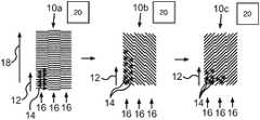
- FIG. 2a schematic representation of three consecutive powder layers 10 a - c is shown in FIG. 2 , which are successively impinged by at least one high-energy beam in a building and joining area within the scope of a method according to the invention for additively manufacturing a component.
- the at least one high-energy beamis moved over the individual powder layers 10 a - c such that in the three shown powder layer regions, which are located one above the other in lowering direction of the component platform, the straight lines of the respective parallel arrangements 16 or exposure strips are each arranged at different angles to the respective linear feed direction 12 .
- the feed directions 12are kept constant in contrast thereto and extend parallel to the main axis 18 of the device used for performing the method in all of the powder layers 10 a - c , whereby the method can be particularly fast and simply performed.
- varied angles between the feed directions 12 and the main axis 18can also be adjusted within a powder layer 10 a - c or in each new powder layer 10 a - c .
- rotating the feed directions 12 of the parallel arrangements 16that is the exposure strip in each powder layer 10 a - c , as shown in FIG.
- angles between the straight lines 14 of adjacent or spaced parallel arrangements 16are differently adjusted within a single powder layer 10 a , 10 b and/or 10 c to also particularly reliably prevent the formation of preferential directions within a powder layer 10 a - c.
- the device used for performing the methodhas one or more induction coils 20 for inductively heating the component or the powder layers 10 a - c . Because the development of preferential directions in the texture of the component material is reliably prevented with the aid of the method according to the invention or the device according to the invention used for performing the method, the possibly present induction coils do not have to be rotatable or otherwise movable, whereby the device can be correspondingly more simply and inexpensively formed and operated.
Landscapes
- Engineering & Computer Science (AREA)
- Physics & Mathematics (AREA)
- Manufacturing & Machinery (AREA)
- Optics & Photonics (AREA)
- Mechanical Engineering (AREA)
- Chemical & Material Sciences (AREA)
- Materials Engineering (AREA)
- Plasma & Fusion (AREA)
- Health & Medical Sciences (AREA)
- General Health & Medical Sciences (AREA)
- Toxicology (AREA)
- Powder Metallurgy (AREA)
Abstract
Description
Claims (7)
Applications Claiming Priority (4)
| Application Number | Priority Date | Filing Date | Title |
|---|---|---|---|
| DE102013224319 | 2013-11-27 | ||
| DE102013224319.7ADE102013224319A1 (en) | 2013-11-27 | 2013-11-27 | Method and device for the generative production of at least one component region of a component |
| DE102013224319.7 | 2013-11-27 | ||
| PCT/EP2014/061877WO2015078595A1 (en) | 2013-11-27 | 2014-06-06 | Method and device for additively manufacturing at least one component region of a component |
Publications (2)
| Publication Number | Publication Date |
|---|---|
| US20160288209A1 US20160288209A1 (en) | 2016-10-06 |
| US10821510B2true US10821510B2 (en) | 2020-11-03 |
Family
ID=51059417
Family Applications (1)
| Application Number | Title | Priority Date | Filing Date |
|---|---|---|---|
| US15/037,835Active2036-03-02US10821510B2 (en) | 2013-11-27 | 2014-06-06 | Method and device for additively manufacturing at least one component region of a component |
Country Status (5)
| Country | Link |
|---|---|
| US (1) | US10821510B2 (en) |
| EP (1) | EP3074161B1 (en) |
| CN (2) | CN110064754B (en) |
| DE (1) | DE102013224319A1 (en) |
| WO (1) | WO2015078595A1 (en) |
Cited By (2)
| Publication number | Priority date | Publication date | Assignee | Title |
|---|---|---|---|---|
| US11110517B2 (en)* | 2015-12-11 | 2021-09-07 | Eos Gmbh Electro Optical Systems | Method and device for examining an input data set of a generative layer building device |
| US12324932B2 (en) | 2022-03-03 | 2025-06-10 | TRUMPF Additive Manufacturing Italia S.r.l. | Method and planning device for planning a locally selective irradiation of a working area, computer program, method and manufacturing device for additively manufacturing an object from a powder material |
Families Citing this family (16)
| Publication number | Priority date | Publication date | Assignee | Title |
|---|---|---|---|---|
| PL3323534T3 (en) | 2013-02-14 | 2019-09-30 | Renishaw Plc | Selective laser solidification method |
| US9669583B2 (en) | 2013-03-15 | 2017-06-06 | Renishaw Plc | Selective laser solidification apparatus and method |
| DE102013205724A1 (en) | 2013-03-28 | 2014-10-02 | Eos Gmbh Electro Optical Systems | Method and device for producing a three-dimensional object |
| US10722943B2 (en) | 2016-01-12 | 2020-07-28 | Hamilton Sundstrand Corporation | Additive manufacturing method |
| JP6855181B2 (en)* | 2016-06-30 | 2021-04-07 | キヤノン株式会社 | 3D modeling device and manufacturing method of 3D modeled object |
| DE102016218647A1 (en) | 2016-09-28 | 2018-03-29 | MTU Aero Engines AG | Device and method for inductive heating of a component |
| GB201700170D0 (en)* | 2017-01-06 | 2017-02-22 | Rolls Royce Plc | Manufacturing method and apparatus |
| US10828700B2 (en)* | 2017-03-06 | 2020-11-10 | General Electric Company | Triangle hatch pattern for additive manufacturing |
| US10668534B2 (en)* | 2017-03-06 | 2020-06-02 | General Electric Company | Leg elimination strategy for hatch pattern |
| US20180264598A1 (en)* | 2017-03-15 | 2018-09-20 | General Electric Company | Constantly varying hatch for additive manufacturing |
| DE102017118831A1 (en)* | 2017-08-17 | 2019-02-21 | Eos Gmbh Electro Optical Systems | Method and device for the additive production of at least one component layer of a component and storage medium |
| DE102017127148A1 (en)* | 2017-11-17 | 2019-05-23 | Eos Gmbh Electro Optical Systems | Radiation strip sorting |
| FR3080306B1 (en)* | 2018-04-19 | 2021-02-19 | Michelin & Cie | ADDITIVE MANUFACTURING PROCESS OF A METAL PART IN THREE DIMENSIONS |
| US11426818B2 (en) | 2018-08-10 | 2022-08-30 | The Research Foundation for the State University | Additive manufacturing processes and additively manufactured products |
| DE102019122983A1 (en)* | 2019-08-27 | 2021-03-04 | Eos Gmbh Electro Optical Systems | Process for additive manufacturing of components, device, process for control and storage medium |
| US12257779B2 (en) | 2020-09-17 | 2025-03-25 | Concept Laser Gmbh | Controlling irradiation parameters of an additive manufacturing machine |
Citations (17)
| Publication number | Priority date | Publication date | Assignee | Title |
|---|---|---|---|---|
| US4778971A (en)* | 1986-05-23 | 1988-10-18 | Kabushiki Kaisha Meidensha | Induction heating apparatus |
| US4863538A (en)* | 1986-10-17 | 1989-09-05 | Board Of Regents, The University Of Texas System | Method and apparatus for producing parts by selective sintering |
| US5155324A (en)* | 1986-10-17 | 1992-10-13 | Deckard Carl R | Method for selective laser sintering with layerwise cross-scanning |
| US20060145381A1 (en)* | 2002-12-19 | 2006-07-06 | Arcam Ab | Arrangement and method for producing a three-dimensional product |
| CN1976800A (en) | 2005-04-06 | 2007-06-06 | Eos有限公司电镀光纤系统 | Device and method for the production of a three-dimensional object |
| US20080241392A1 (en) | 2007-03-27 | 2008-10-02 | Eos Gmbh Electro Optical Systems | Method and Device for Manufacturing a Three-Dimensional Object |
| US20090183850A1 (en)* | 2008-01-23 | 2009-07-23 | Siemens Power Generation, Inc. | Method of Making a Combustion Turbine Component from Metallic Combustion Turbine Subcomponent Greenbodies |
| CN101835554A (en) | 2007-10-26 | 2010-09-15 | 松下电工株式会社 | Device and method for manufacturing metal powder sintered part |
| DE102009051479A1 (en) | 2009-10-30 | 2011-05-05 | Mtu Aero Engines Gmbh | Method and device for producing a component of a turbomachine |
| CN102143813A (en) | 2008-07-08 | 2011-08-03 | 贝斯娜株式会社 | Micro drill and fabricating method thereof |
| CN102553484A (en) | 2010-10-29 | 2012-07-11 | Eos有限公司电镀光纤系统 | Device for processing powder for a device for manufacturing a three-dimensional object and device for manufacturing a three-dimensional object |
| WO2013041195A2 (en) | 2011-09-22 | 2013-03-28 | Mtu Aero Engines Gmbh | Multi-frequency induction heating of generatively produced components |
| US20130163967A1 (en)* | 2011-12-21 | 2013-06-27 | Freiberger Compound Materials Gmbh | Device and method of evaporating a material from a metal melt |
| DE102012206122A1 (en) | 2012-04-13 | 2013-10-17 | MTU Aero Engines AG | Multiple coil arrangement for a device for the generative production of components and corresponding manufacturing method |
| EP2772329A1 (en) | 2013-02-28 | 2014-09-03 | Alstom Technology Ltd | Method for manufacturing a hybrid component |
| US20160001509A1 (en)* | 2014-07-03 | 2016-01-07 | United Technologies Corporation | Additive manufacturing system and method of additive manufacture utilizing layer-by-layer thermo-mechanical analysis |
| US20170106593A1 (en)* | 2015-10-14 | 2017-04-20 | Lawrence Livermore National Security, Llc | Spatter reduction laser scanning strategy in selective laser melting |
Family Cites Families (3)
| Publication number | Priority date | Publication date | Assignee | Title |
|---|---|---|---|---|
| US20050242473A1 (en)* | 2004-04-28 | 2005-11-03 | 3D Systems, Inc. | Uniform thermal distribution imaging |
| CN101626881B (en)* | 2007-01-17 | 2012-11-14 | 3D系统公司 | Imager assembly and method for solid imaging |
| RU2539135C2 (en)* | 2012-02-27 | 2015-01-10 | Юрий Александрович Чивель | Production of 3d articles of powders and device to this end |
- 2013
- 2013-11-27DEDE102013224319.7Apatent/DE102013224319A1/enactivePending
- 2014
- 2014-06-06CNCN201910012909.1Apatent/CN110064754B/enactiveActive
- 2014-06-06EPEP14734410.5Apatent/EP3074161B1/enactiveActive
- 2014-06-06USUS15/037,835patent/US10821510B2/enactiveActive
- 2014-06-06WOPCT/EP2014/061877patent/WO2015078595A1/enactiveApplication Filing
- 2014-06-06CNCN201480065178.2Apatent/CN106029262A/enactivePending
Patent Citations (20)
| Publication number | Priority date | Publication date | Assignee | Title |
|---|---|---|---|---|
| US4778971A (en)* | 1986-05-23 | 1988-10-18 | Kabushiki Kaisha Meidensha | Induction heating apparatus |
| US4863538A (en)* | 1986-10-17 | 1989-09-05 | Board Of Regents, The University Of Texas System | Method and apparatus for producing parts by selective sintering |
| US5155324A (en)* | 1986-10-17 | 1992-10-13 | Deckard Carl R | Method for selective laser sintering with layerwise cross-scanning |
| US20060145381A1 (en)* | 2002-12-19 | 2006-07-06 | Arcam Ab | Arrangement and method for producing a three-dimensional product |
| CN1976800A (en) | 2005-04-06 | 2007-06-06 | Eos有限公司电镀光纤系统 | Device and method for the production of a three-dimensional object |
| US20080241392A1 (en) | 2007-03-27 | 2008-10-02 | Eos Gmbh Electro Optical Systems | Method and Device for Manufacturing a Three-Dimensional Object |
| DE102007014683A1 (en) | 2007-03-27 | 2008-10-09 | Eos Gmbh Electro Optical Systems | Method and device for producing a three-dimensional object |
| US8034279B2 (en)* | 2007-03-27 | 2011-10-11 | Eos Gmbh Electro Optical Systems | Method and device for manufacturing a three-dimensional object |
| CN101835554A (en) | 2007-10-26 | 2010-09-15 | 松下电工株式会社 | Device and method for manufacturing metal powder sintered part |
| US20090183850A1 (en)* | 2008-01-23 | 2009-07-23 | Siemens Power Generation, Inc. | Method of Making a Combustion Turbine Component from Metallic Combustion Turbine Subcomponent Greenbodies |
| CN102143813A (en) | 2008-07-08 | 2011-08-03 | 贝斯娜株式会社 | Micro drill and fabricating method thereof |
| DE102009051479A1 (en) | 2009-10-30 | 2011-05-05 | Mtu Aero Engines Gmbh | Method and device for producing a component of a turbomachine |
| US10144062B2 (en)* | 2009-10-30 | 2018-12-04 | Mtu Aero Engines Gmbh | Method and device for producing a component of a turbomachine |
| CN102553484A (en) | 2010-10-29 | 2012-07-11 | Eos有限公司电镀光纤系统 | Device for processing powder for a device for manufacturing a three-dimensional object and device for manufacturing a three-dimensional object |
| WO2013041195A2 (en) | 2011-09-22 | 2013-03-28 | Mtu Aero Engines Gmbh | Multi-frequency induction heating of generatively produced components |
| US20130163967A1 (en)* | 2011-12-21 | 2013-06-27 | Freiberger Compound Materials Gmbh | Device and method of evaporating a material from a metal melt |
| DE102012206122A1 (en) | 2012-04-13 | 2013-10-17 | MTU Aero Engines AG | Multiple coil arrangement for a device for the generative production of components and corresponding manufacturing method |
| EP2772329A1 (en) | 2013-02-28 | 2014-09-03 | Alstom Technology Ltd | Method for manufacturing a hybrid component |
| US20160001509A1 (en)* | 2014-07-03 | 2016-01-07 | United Technologies Corporation | Additive manufacturing system and method of additive manufacture utilizing layer-by-layer thermo-mechanical analysis |
| US20170106593A1 (en)* | 2015-10-14 | 2017-04-20 | Lawrence Livermore National Security, Llc | Spatter reduction laser scanning strategy in selective laser melting |
Non-Patent Citations (7)
| Title |
|---|
| CN101835554 (Year: 2008).* |
| Developer of Selective Laser Melting Looks toward New Applications for the Generative Manufacturing Process, European Tool & Mould Making, May 2010. |
| Development of Processing Strategies for the Additive Layer Manufacture of Aeropspace Components in Inconel 718, Robert James Deffley, Department of Materials Science and Engineering, The University of Sheffield,pp. 95-96, Jan. 2012. |
| English Translation of (DE102009051479A1)'s claims (Year: 2009).* |
| Part and material properties in selective laser melting of metals, J.-P. Kruth, et al., The 16th International Symposium on Electromachining (ISEM-XVI), CIRP Sponsored Conference, Apr. 19-23, 2010, Shanghai, China. |
| Part and material properties in selective laser melting of metals, J.-P. Kruth, et al., The 16th International Symposium on Electromachining (ISEM—XVI), CIRP Sponsored Conference, Apr. 19-23, 2010, Shanghai, China. |
| Scanning patterns for selective laser melting, Inside Metal Additive Manufacturing, Jan. 30, 2015. |
Cited By (4)
| Publication number | Priority date | Publication date | Assignee | Title |
|---|---|---|---|---|
| US11110517B2 (en)* | 2015-12-11 | 2021-09-07 | Eos Gmbh Electro Optical Systems | Method and device for examining an input data set of a generative layer building device |
| US20210346957A1 (en)* | 2015-12-11 | 2021-11-11 | Eos Gmbh Electro Optical Systems | Method and device for examining an input data set of a generative layer building device |
| US11975479B2 (en)* | 2015-12-11 | 2024-05-07 | Eos Gmbh Electro Optical Systems | Method and device for examining an input data set of a generative layer building device |
| US12324932B2 (en) | 2022-03-03 | 2025-06-10 | TRUMPF Additive Manufacturing Italia S.r.l. | Method and planning device for planning a locally selective irradiation of a working area, computer program, method and manufacturing device for additively manufacturing an object from a powder material |
Also Published As
| Publication number | Publication date |
|---|---|
| EP3074161B1 (en) | 2023-11-29 |
| EP3074161C0 (en) | 2023-11-29 |
| EP3074161A1 (en) | 2016-10-05 |
| CN110064754A (en) | 2019-07-30 |
| DE102013224319A1 (en) | 2015-06-11 |
| CN106029262A (en) | 2016-10-12 |
| WO2015078595A1 (en) | 2015-06-04 |
| CN110064754B (en) | 2022-08-02 |
| US20160288209A1 (en) | 2016-10-06 |
Similar Documents
| Publication | Publication Date | Title |
|---|---|---|
| US10821510B2 (en) | Method and device for additively manufacturing at least one component region of a component | |
| US10201853B2 (en) | Multiple coil arrangement for a device for generative production of components and corresponding production method | |
| US11583931B2 (en) | Powder-bed additive manufacturing devices and methods | |
| US20220362886A1 (en) | Layered manufacturing of single crystal alloy components | |
| US10464170B2 (en) | Temperature regulation for a device for the additive manufacturing of components and corresponding production method | |
| US20160368051A1 (en) | Device and method for additively producing at least one component region of a component | |
| US20160368052A1 (en) | Device and method for additively producing at least one component region of a component | |
| Wang et al. | Process modeling in laser deposition of multilayer SS410 steel | |
| CN103945962B (en) | Method for producing components by selective irradiation of a powder bed | |
| KR20160013101A (en) | Method and apparatus for additive manufacturing | |
| US10259172B2 (en) | Fabrication method of magnetic device | |
| Shi et al. | Closed-loop control of variable width deposition in laser metal deposition | |
| US12028956B2 (en) | Large scale metal forming | |
| TW201524650A (en) | Apparatus and method for controlling the additive manufacturing | |
| RU2006147226A (en) | METHOD AND DEVICE FOR MANUFACTURING THREE-DIMENSIONAL OBJECT | |
| JPWO2017081812A1 (en) | 3D additive manufacturing equipment | |
| JP2017141510A (en) | Additive manufacturing employing plural electron beam sources | |
| Obidigbo et al. | Processing parameter and transient effects on melt pool geometry in additive manufacturing of Invar 36 | |
| Pacurar et al. | Research on how to improve the accuracy of the SLM metallic parts | |
| CN105383062B (en) | Manufacture the device and its temperature control system, method of three-dimensional body | |
| US20220008997A1 (en) | Regulation method for additive manufacturing | |
| US11376692B2 (en) | Articles of manufacture and methods for additive manufacturing of articles having desired magnetic anisotropy | |
| JP6830775B2 (en) | Induction heating device and induction heating method |
Legal Events
| Date | Code | Title | Description |
|---|---|---|---|
| AS | Assignment | Owner name:MTU AERO ENGINES AG, GERMANY Free format text:ASSIGNMENT OF ASSIGNORS INTEREST;ASSIGNORS:JAKIMOV, ANDREAS;SCHLICK, GEORG;HANRIEDER, HERBERT;AND OTHERS;SIGNING DATES FROM 20160318 TO 20160406;REEL/FRAME:038647/0151 Owner name:EOS GMBH ELECTRO OPTICAL SYSTEMS, GERMANY Free format text:ASSIGNMENT OF ASSIGNORS INTEREST;ASSIGNORS:JAKIMOV, ANDREAS;SCHLICK, GEORG;HANRIEDER, HERBERT;AND OTHERS;SIGNING DATES FROM 20160318 TO 20160406;REEL/FRAME:038647/0151 | |
| STPP | Information on status: patent application and granting procedure in general | Free format text:RESPONSE TO NON-FINAL OFFICE ACTION ENTERED AND FORWARDED TO EXAMINER | |
| STPP | Information on status: patent application and granting procedure in general | Free format text:FINAL REJECTION MAILED | |
| STPP | Information on status: patent application and granting procedure in general | Free format text:DOCKETED NEW CASE - READY FOR EXAMINATION | |
| STPP | Information on status: patent application and granting procedure in general | Free format text:NON FINAL ACTION MAILED | |
| STPP | Information on status: patent application and granting procedure in general | Free format text:RESPONSE TO NON-FINAL OFFICE ACTION ENTERED AND FORWARDED TO EXAMINER | |
| STPP | Information on status: patent application and granting procedure in general | Free format text:NOTICE OF ALLOWANCE MAILED -- APPLICATION RECEIVED IN OFFICE OF PUBLICATIONS | |
| STPP | Information on status: patent application and granting procedure in general | Free format text:PUBLICATIONS -- ISSUE FEE PAYMENT VERIFIED | |
| STCF | Information on status: patent grant | Free format text:PATENTED CASE | |
| AS | Assignment | Owner name:EOS GMBH ELECTRO OPTICAL SYSTEMS, GERMANY Free format text:ASSIGNMENT OF ASSIGNORS INTEREST;ASSIGNOR:MTU AERO ENGINES AG;REEL/FRAME:058347/0305 Effective date:20210809 | |
| MAFP | Maintenance fee payment | Free format text:PAYMENT OF MAINTENANCE FEE, 4TH YEAR, LARGE ENTITY (ORIGINAL EVENT CODE: M1551); ENTITY STATUS OF PATENT OWNER: LARGE ENTITY Year of fee payment:4 |