US10821320B2 - Cushion assembly of a treadmill - Google Patents
Cushion assembly of a treadmillDownload PDFInfo
- Publication number
- US10821320B2 US10821320B2US16/181,429US201816181429AUS10821320B2US 10821320 B2US10821320 B2US 10821320B2US 201816181429 AUS201816181429 AUS 201816181429AUS 10821320 B2US10821320 B2US 10821320B2
- Authority
- US
- United States
- Prior art keywords
- treadmill
- supporting element
- buffering
- frame
- cushion
- Prior art date
- Legal status (The legal status is an assumption and is not a legal conclusion. Google has not performed a legal analysis and makes no representation as to the accuracy of the status listed.)
- Expired - Fee Related, expires
Links
Images


Classifications
- A—HUMAN NECESSITIES
- A63—SPORTS; GAMES; AMUSEMENTS
- A63B—APPARATUS FOR PHYSICAL TRAINING, GYMNASTICS, SWIMMING, CLIMBING, OR FENCING; BALL GAMES; TRAINING EQUIPMENT
- A63B22/00—Exercising apparatus specially adapted for conditioning the cardio-vascular system, for training agility or co-ordination of movements
- A63B22/02—Exercising apparatus specially adapted for conditioning the cardio-vascular system, for training agility or co-ordination of movements with movable endless bands, e.g. treadmills
- A63B22/0207—Exercising apparatus specially adapted for conditioning the cardio-vascular system, for training agility or co-ordination of movements with movable endless bands, e.g. treadmills having shock absorbing means
- A63B22/0214—Exercising apparatus specially adapted for conditioning the cardio-vascular system, for training agility or co-ordination of movements with movable endless bands, e.g. treadmills having shock absorbing means between the belt supporting deck and the frame
- A—HUMAN NECESSITIES
- A63—SPORTS; GAMES; AMUSEMENTS
- A63B—APPARATUS FOR PHYSICAL TRAINING, GYMNASTICS, SWIMMING, CLIMBING, OR FENCING; BALL GAMES; TRAINING EQUIPMENT
- A63B2209/00—Characteristics of used materials
- A—HUMAN NECESSITIES
- A63—SPORTS; GAMES; AMUSEMENTS
- A63B—APPARATUS FOR PHYSICAL TRAINING, GYMNASTICS, SWIMMING, CLIMBING, OR FENCING; BALL GAMES; TRAINING EQUIPMENT
- A63B71/00—Games or sports accessories not covered in groups A63B1/00 - A63B69/00
- A63B71/0054—Features for injury prevention on an apparatus, e.g. shock absorbers
Definitions
- the present inventionrelates to a treadmill and, more particularly, to a cushion assembly of a treadmill.
- a treadmillincludes an arched tread assembly including two belts 21, a number of slats 22 and a cushion 31.
- Each belt 21includes apertures 28.
- Each slat 22includes a rigid element 30 and two threaded bolts 35.
- the rigid element 30includes two apertures 301, an external face, and an internal face in contact with the belts 21.
- a middle section 352 of each threaded bolt 35is inserted in a corresponding aperture 301 of the rigid element 30 so that the threaded bolts 35 cannot be rotated relative to the rigid element 30.
- a terminal section 351 of each threaded bolt 35is located on an external face of the rigid element 30.
- the cushion 31includes an internal face in contact with the external face of the rigid element 30 and an external face extending higher than the first external section 351 of each of the threaded bolts 35.
- the cushion 31absorbs shocks and reduces noise when the treadmill is in operation.
- the cushion 31, which is particularly useful for the arched tread assemblyis complicated, the assembling of the treadmill is hence troublesome, and the cost of the treadmill is hence high.
- the present inventionis therefore intended to obviate or at least alleviate the problems encountered in prior art.
- the cushion assemblyincludes a supporting element and at least one buffering element.
- An upper portion of a tread assembly of the treadmillis supported on the supporting element.
- the buffering elementis provided between the supporting element and a frame of the treadmill.
- FIG. 1is a perspective view of a treadmill provided with a cushion assembly according to a first embodiment of the present invention
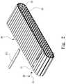
- FIG. 2is a perspective view of a running belt of the treadmill shown in FIG. 1 ;
- FIG. 3is a top view of the treadmill shown in FIG. 1 without the running belt shown in FIG. 2 ;
- FIG. 4is a cross-sectional view of the treadmill taken along a line B-B shown in FIG. 3 ;
- FIG. 5is an enlarged partial view of the treadmill shown in FIG. 4 ;
- FIG. 6is a cross-sectional view of the treadmill taken along a line C-C shown in FIG. 4 ;
- FIG. 7is an enlarged partial view of the treadmill shown in FIG. 6 ;
- FIG. 8is an enlarged partial cross-sectional view of a cushion assembly according to a second embodiment of the present invention.
- FIG. 9is a cross-sectional view of a treadmill provided with a cushion assembly according to a third embodiment of the present invention.
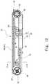
- FIG. 10is a cross-sectional view of the treadmill taken along a line D-D shown in FIG. 9 ;
- FIG. 11is a cross-sectional view of a treadmill provided with a cushion assembly according to a fourth embodiment of the present invention.
- FIG. 12is a cross-sectional view of a treadmill provided with a cushion assembly according to a fifth embodiment of the present invention.
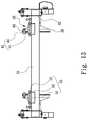
- FIG. 13is a cross-sectional view of the cushion assembly taken along a line E-E shown in FIG. 12 .
- a treadmill 10is equipped with a tread assembly 20 , a frame 30 and two cushion assemblies 40 according to a first embodiment of the present invention.
- the treadmill 10is formed with a rear end 12 and a front end 14 .
- the tread assembly 20is movably supported on the frame 30 .
- the tread assembly 20includes an upper portion that preferably extends horizontally when the treadmill 10 is in operation.
- the frame 30includes three crossbars 31 located between and connected to two lateral bars 32 .
- the crossbars 31 and the lateral bars 32are tubes.
- a shell(not shown) can be connected to each of the lateral bars 32 by threaded bolts, rivets or soldering for example. Such shells are intended to protect the frame 30 .
- a major axle 33 , a motor 36 and a minor axle 37are supported on the frame 30 .
- the major axle 33is supported on the lateral bars 32 .
- Two major wheels 34are connected to the major axle 33 so that they are rotatable together.
- the minor axle 37is rotationally supported on the lateral bars 32 .
- the major axle 33 and the minor axle 37are located near two opposite ends of the frame 30 .
- Two minor wheels 38are connected to the minor axle 37 so that they are rotatable together.
- the major wheels 34 and the minor wheels 38are supported on the cushion assembly 40 in a manner to be described.
- the motor 36is connected to at least one of the crossbars 31 .
- the motor 36is connected to the major axle 33 via a transmission 35 so that the major axle 33 is rotatable by the motor 36 .
- the transmission 35is a pulley-and-belt combination.
- the transmission 35can however be a gear train, a sprocket-and-chain combination or any other proper transmission
- the tread assembly 20is shaped like a caterpillar.
- the tread assembly 20includes two loops 21 connected to a number of slats 24 .
- the slats 24are kept in position relative to the loops 21 by linking strips 25 and fasteners 26 .
- Each of the loops 21includes a number of engagement portions 22 and a tracking portion 23 .
- the tracking portions 23 of the loops 21are located between the series of engagement portions 22 of the loops 21 .
- the tread assembly 20extends around the major axle 33 and the minor axle 37 .
- Each of the loops 21extends around a corresponding one of the major wheels 34 and a corresponding one of the minor wheels 38 .
- the engagement portions 22 of the loops 21are engaged with corresponding portions of the major wheels 34 so that the loops 21 are drivable by the major wheels 34 .
- the motor 36rotates the major axle 33 via the transmission 35 .
- the major wheel 34cooperates with the minor wheel 38 to drive the tread assembly 20 on the frame 30 . More details of the engagement of the tread assembly 20 with the major wheel 34 are given in U.S. patent application Ser. No. 16/030,839.
- each of the cushion assemblies 40is connected to the frame 30 .
- Each of the cushion assemblies 40includes a supporting element 41 , a group of guiding wheels 42 , a group of rollers 43 and two buffering elements 46 .
- the supporting element 41includes a vertical portion 44 and a horizontal portion 45 , thereby rendering the supporting element 41 L-shaped ( FIG. 7 ).
- the guiding wheels 42 and the rollers 43are supported on a same side of the vertical portion 44 of the supporting element 41 .
- the diameter of the guiding wheels 42is larger than that of the rollers 43 .
- Each of the guiding wheels 42includes a groove 423 in the periphery 422 .
- the periphery 422 of each of the guiding wheels 42includes a middle portion extending in the groove 423 .
- the radius 421 of the middle portion of the periphery 422 of each of the guiding wheels 42is identical to the radius 431 of the periphery 432 of each of the rollers 43 .
- the middle portions of the peripheries 422 of the guiding wheels 42 and the peripheries 432 of the rollers 43share a tangent plane.
- the tangent planeis located above the edge of the vertical portion 44 , thereby keeping the corresponding loop 21 away from the edge of the vertical portion 44 of the supporting element 41 .
- the tracking portion 23 of the corresponding loop 21is inserted in the grooves 423 of the guiding wheels 42 , thereby preventing the corresponding loop 21 from transverse movement relative to the guiding wheels 42 .
- the tracking portion 23 of the corresponding loop 21contacts the middle portions of the peripheries 422 of the guiding wheels 42 and the peripheries 432 of the rollers 43 , thereby rending the upper portion of the tread assembly 20 horizontally movable on the horizontal portions 45 of the supporting elements 41 of the cushion assemblies 40 .
- one of the buffering elements 46is sandwiched between a portion of the supporting element 41 and one of the crossbars 31 near the rear end 12 of the treadmill 10 .
- the other buffering element 46is sandwiched between another portion of the supporting element 41 and another one of the crossbars 31 near the front end 14 of the treadmill 10 .
- Each of the buffering elements 46is sandwiched between a corresponding plate 47 and the horizontal portion 45 of the supporting element 41 .
- Two fasteners 49are inserted in the horizontal portion 45 of the supporting element 41 , each of the buffering elements 46 and the corresponding one of the plates 47 .
- Each of the fasteners 49is preferably a screw with a threaded portion inserted in a screw hole made in the corresponding plate 47 and an enlarged head located on the horizontal portion 45 of the supporting element 41 .
- the horizontal portion 45 of the supporting element 41is movable relative to the plates 47 along the fasteners 49 .
- the horizontal portion 45 of the supporting element 41 , the buffering elements 46 and the plates 47cannot be detached from one another.
- Each of the buffering elements 46is an elastic block or pad made of polyurethane (“PU”) in the first embodiment.
- the buffering elements 46can be made of rubber in another embodiment.
- each of the buffering elements 46can be a helical or leaf spring in another embodiment.
- Each of the plate 47is a metal plate in the first embodiment.
- the plates 47are attached to the crossbars 31 by soldering for example. Thus, there are points of solder 48 to connect the cushion assembly 40 to the frame 30 .
- the slats 24 of the tread assembly 20bear the weight of the user.
- the weightis transferred to the loops 21 from the slats 24 .
- the weightis transferred to the supporting elements 41 from the loops 21 since the guiding wheels 42 and the rollers 43 contact the loops 21 .
- the supporting elements 41are moved toward the crossbars 31 , and the buffering elements 46 are compressed.
- the buffering elements 46reduce an impact on the tread assembly 20 from the user and protect the user's ankles, knees and some other joints, thereby protecting the user from injuries.
- FIG. 8there is a treadmill 10 according to a second embodiment of the present invention.
- the second embodimentis identical to the first embodiment except for two things. Firstly, the fasteners 49 are only inserted in the horizontal portion 45 and the buffering elements 46 , not in the plates 47 . Secondly, two fasteners 491 are used to connect the buffering elements 46 to the horizontal portion 45 of the supporting element 41 .
- Each of the fasteners 491includes an enlarged head embedded in a corresponding one of the buffering element 46 and a threaded portion extending throughout two apertures made in a corresponding one of the plates 47 and engaged with a corresponding nut 492 .
- each of the buffering elements 46is kept between the corresponding plate 47 and the horizontal portion 45 of the supporting element 41 .
- each of the buffering units 461includes a mount 462 , several elastic rods 463 and a plate 466 .
- the mount 462is connected to a corresponding one of the crossbar 31 by soldering for example.
- the elastic rods 463are made of PU for example.
- Each of the elastic rods 463includes a protuberance 464 extending from an end and a recess 465 made in an opposite end.
- each elastic rod 463is fitted in a bore (not numbered) made in the mount 462 , thereby connecting the elastic rod 463 to the mount 462 .
- the recess 465receives the threaded portion of a corresponding one of the fasteners 49 that extends throughout a corresponding one of multiple orifices (not numbered) in the horizontal portion 45 of the supporting element 41 and a corresponding one of multiple apertures (not numbered) in the plate 466 .
- each of the buffering units 461is sandwiched between the horizontal portion 45 of the supporting element 41 and the corresponding mount 462 , which is connected to the corresponding crossbar 31 .
- each of the cushion assemblies 40includes a single buffering unit 461 and a pivotal unit 50 .
- the pivotal unit 50is used to connect a first portion of the supporting element 41 to a portion of the frame 30 in the vicinity of the rear end 12 of the treadmill 10 .
- the buffering unit 461is provided between a second portion of the supporting element 41 and the crossbar 31 near the front end 14 of the treadmill 10 . Therefore, the first portion of the supporting element 41 is allowed to move down as the buffering unit 461 is compressed while the second portion of the supporting element 41 is allowed to pivot about the pivotal unit 50 .
- the buffering effectis better near the front end 14 of the treadmill 10 than near the rear end 12 .
- FIGS. 12 and 13there is a treadmill 10 according to a fifth embodiment of the present invention.
- the fifth embodimentis like the fourth embodiment except that the buffering unit 461 is provided between the first portion of the supporting element 41 and the crossbar 31 near the rear end 12 of the treadmill 10 while the pivotal unit 50 is used to connect the second portion of the supporting element 41 to a portion of the frame 30 near the front end 14 of the treadmill 10 .
- the second portion of the supporting element 41is allowed to move down as the buffering unit 461 is compressed while the first portion of the supporting element 41 is allowed to pivot about the pivotal unit 50 .
- the buffering effectis better near the rear end 12 of the treadmill 10 than near the front end 14 .
- the pivotal unit 50includes a sleeve 51 , a pivot 52 and a mount 53 .
- the mount 53is U-shaped element connected to one of the crossbars 31 by soldering for example.
- the sleeve 51is connected to a lower face of the horizontal portion 45 of the supporting element 41 by soldering for example.
- the sleeve 51is inserted in the mount 53 .
- the pivot 52is inserted in the sleeve 51 and the mount 53 .
- the pivot 52is in the form of a threaded bolt.
Landscapes
- Health & Medical Sciences (AREA)
- Cardiology (AREA)
- Vascular Medicine (AREA)
- General Health & Medical Sciences (AREA)
- Physical Education & Sports Medicine (AREA)
- Rehabilitation Tools (AREA)
Abstract
Description
Claims (1)
Applications Claiming Priority (3)
| Application Number | Priority Date | Filing Date | Title |
|---|---|---|---|
| TW107206075U | 2018-05-10 | ||
| TW107206075UTWM568153U (en) | 2018-05-10 | 2018-05-10 | Cushioning mechanism for horizontal track treadmill |
| TW107206075 | 2018-05-10 |
Publications (2)
| Publication Number | Publication Date |
|---|---|
| US20190344117A1 US20190344117A1 (en) | 2019-11-14 |
| US10821320B2true US10821320B2 (en) | 2020-11-03 |
Family
ID=64871074
Family Applications (1)
| Application Number | Title | Priority Date | Filing Date |
|---|---|---|---|
| US16/181,429Expired - Fee RelatedUS10821320B2 (en) | 2018-05-10 | 2018-11-06 | Cushion assembly of a treadmill |
Country Status (3)
| Country | Link |
|---|---|
| US (1) | US10821320B2 (en) |
| CN (1) | CN209548601U (en) |
| TW (1) | TWM568153U (en) |
Cited By (1)
| Publication number | Priority date | Publication date | Assignee | Title |
|---|---|---|---|---|
| US12324951B2 (en)* | 2022-08-25 | 2025-06-10 | Yu-Lun TSAI | Treadmill |
Families Citing this family (2)
| Publication number | Priority date | Publication date | Assignee | Title |
|---|---|---|---|---|
| KR102080163B1 (en)* | 2019-02-11 | 2020-04-07 | 주식회사 디랙스 | treadmill |
| IT202100012869A1 (en)* | 2021-05-19 | 2022-11-19 | Technogym Spa | Walking belt exercise machine. |
Citations (29)
| Publication number | Priority date | Publication date | Assignee | Title |
|---|---|---|---|---|
| US3941377A (en)* | 1974-11-19 | 1976-03-02 | Hakon Lie | Apparatus for simulated skiing |
| US4334676A (en)* | 1974-10-11 | 1982-06-15 | Wilhelm Schonenberger | Movable surface apparatus, particularly for physical exercise and training |
| US4509510A (en)* | 1981-12-28 | 1985-04-09 | Hook Clarence L | Massage tread for human skin |
| US4925183A (en)* | 1987-06-01 | 1990-05-15 | Kim Sang Sup | Indoor-rollbike apparatus |
| US5158073A (en)* | 1990-12-18 | 1992-10-27 | Bukowski Voytek Z | Acupressure foot massage mat |
| US5250067A (en)* | 1992-11-30 | 1993-10-05 | Ala Gelfer | Body treatment pad having a multiple number of sharpened skin-penetration protuberances |
| US5470293A (en)* | 1992-11-12 | 1995-11-28 | Woodway Ag | Toothed-belt, V-belt, and pulley assembly, for treadmills |
| US5527241A (en)* | 1995-08-31 | 1996-06-18 | Peng; Yue-Hong | Jogging exerciser |
| US5690587A (en)* | 1993-04-21 | 1997-11-25 | Gruenangerl; Johann | Treadmill with cushioned surface, automatic speed control and interface to external devices |
| US6042514A (en)* | 1998-05-30 | 2000-03-28 | Abelbeck; Kevin G. | Moving surface exercise device |
| US6162150A (en)* | 1998-04-13 | 2000-12-19 | Lee; Joseph Chen Lung | Foot massaging exercising apparatus |
| US20020177511A1 (en)* | 2001-05-26 | 2002-11-28 | Jong-Hyeon Jang | Waist exercising device |
| US6860836B1 (en)* | 2004-01-13 | 2005-03-01 | Yu Feng Wu | Rock climbing exerciser for indoor use |
| US6918859B1 (en)* | 2003-01-24 | 2005-07-19 | Don-Lon Yeh | Dynamic sole-massaging machine with mutiple functions of joints soothing and blood circulation stimulating |
| US20050221959A1 (en)* | 2003-01-24 | 2005-10-06 | Don-Lon Yeh | Dynamic magnetic health bed |
| US7195582B2 (en)* | 2005-04-21 | 2007-03-27 | Yu Feng Wu | Rock climbing apparatus |
| US20070275827A1 (en)* | 2006-05-25 | 2007-11-29 | Ukarma Corporation (A Nv Corp) | Yoga mat |
| US20080176719A1 (en)* | 2007-01-19 | 2008-07-24 | World Wide Stationery Manufacturing Company Limited | Foot massaging treadmill |
| US7510511B2 (en)* | 2005-07-11 | 2009-03-31 | Von Detten Volker | Exercise treadmill having a simulated cobblestone running surface |
| US20090088301A1 (en)* | 2007-09-28 | 2009-04-02 | Johnson Health Tech Co., Ltd. | Treadmill with cushion assembly |
| US20090170666A1 (en)* | 2007-12-27 | 2009-07-02 | Odenwald Wood Products Co., Ltd. | Support Deck for Treadmill |
| US7976437B1 (en)* | 2010-04-30 | 2011-07-12 | Von Detten Volker | Exercise treadmill having a simulated cobblestone running surface |
| US20120129654A1 (en)* | 2010-11-22 | 2012-05-24 | Leao Wang | Electric cushioning mechanism of a treadmill |
| US20120283070A1 (en)* | 2011-05-03 | 2012-11-08 | American Motion Fitness Products Inc. | Treadmill foldable into a chair |
| US20130035214A1 (en)* | 2011-08-03 | 2013-02-07 | Leao Wang | Cushioning mechanism of a treadmill |
| US20130130869A1 (en)* | 2011-11-22 | 2013-05-23 | Kuang-Hua HOU | Platform for supporting conveyor belt of treadmill |
| US20130130868A1 (en)* | 2011-11-22 | 2013-05-23 | Kuang-Hua HOU | Hardness-adjustable platform for supporting conveyor belt of treadmill |
| US20180008862A1 (en)* | 2014-12-18 | 2018-01-11 | Zhe Jiang Feng Shang Techonology Co., Ltd. | Independent suspension vibration damping mechanism of running platform of a treadmill |
| US20180056119A1 (en)* | 2015-02-12 | 2018-03-01 | Zhe Jiang Feng Shang Techonology Co., Ltd. | Low noise direct drive treadmill |
- 2018
- 2018-05-10TWTW107206075Upatent/TWM568153U/ennot_activeIP Right Cessation
- 2018-10-26CNCN201821753947.XUpatent/CN209548601U/enactiveActive
- 2018-11-06USUS16/181,429patent/US10821320B2/ennot_activeExpired - Fee Related
Patent Citations (33)
| Publication number | Priority date | Publication date | Assignee | Title |
|---|---|---|---|---|
| US4334676A (en)* | 1974-10-11 | 1982-06-15 | Wilhelm Schonenberger | Movable surface apparatus, particularly for physical exercise and training |
| US3941377A (en)* | 1974-11-19 | 1976-03-02 | Hakon Lie | Apparatus for simulated skiing |
| US4509510A (en)* | 1981-12-28 | 1985-04-09 | Hook Clarence L | Massage tread for human skin |
| US4925183A (en)* | 1987-06-01 | 1990-05-15 | Kim Sang Sup | Indoor-rollbike apparatus |
| US5158073A (en)* | 1990-12-18 | 1992-10-27 | Bukowski Voytek Z | Acupressure foot massage mat |
| US5470293A (en)* | 1992-11-12 | 1995-11-28 | Woodway Ag | Toothed-belt, V-belt, and pulley assembly, for treadmills |
| US5250067A (en)* | 1992-11-30 | 1993-10-05 | Ala Gelfer | Body treatment pad having a multiple number of sharpened skin-penetration protuberances |
| US5690587A (en)* | 1993-04-21 | 1997-11-25 | Gruenangerl; Johann | Treadmill with cushioned surface, automatic speed control and interface to external devices |
| US5527241A (en)* | 1995-08-31 | 1996-06-18 | Peng; Yue-Hong | Jogging exerciser |
| US6162150A (en)* | 1998-04-13 | 2000-12-19 | Lee; Joseph Chen Lung | Foot massaging exercising apparatus |
| US6042514A (en)* | 1998-05-30 | 2000-03-28 | Abelbeck; Kevin G. | Moving surface exercise device |
| US20020177511A1 (en)* | 2001-05-26 | 2002-11-28 | Jong-Hyeon Jang | Waist exercising device |
| US6918859B1 (en)* | 2003-01-24 | 2005-07-19 | Don-Lon Yeh | Dynamic sole-massaging machine with mutiple functions of joints soothing and blood circulation stimulating |
| US20050221959A1 (en)* | 2003-01-24 | 2005-10-06 | Don-Lon Yeh | Dynamic magnetic health bed |
| US6860836B1 (en)* | 2004-01-13 | 2005-03-01 | Yu Feng Wu | Rock climbing exerciser for indoor use |
| US7195582B2 (en)* | 2005-04-21 | 2007-03-27 | Yu Feng Wu | Rock climbing apparatus |
| US7510511B2 (en)* | 2005-07-11 | 2009-03-31 | Von Detten Volker | Exercise treadmill having a simulated cobblestone running surface |
| US20070275827A1 (en)* | 2006-05-25 | 2007-11-29 | Ukarma Corporation (A Nv Corp) | Yoga mat |
| US20080176719A1 (en)* | 2007-01-19 | 2008-07-24 | World Wide Stationery Manufacturing Company Limited | Foot massaging treadmill |
| US20090088301A1 (en)* | 2007-09-28 | 2009-04-02 | Johnson Health Tech Co., Ltd. | Treadmill with cushion assembly |
| US7563205B2 (en)* | 2007-09-28 | 2009-07-21 | Johnson Health Tech. Co., Ltd. | Treadmill with cushion assembly |
| US20090170666A1 (en)* | 2007-12-27 | 2009-07-02 | Odenwald Wood Products Co., Ltd. | Support Deck for Treadmill |
| US7976437B1 (en)* | 2010-04-30 | 2011-07-12 | Von Detten Volker | Exercise treadmill having a simulated cobblestone running surface |
| US20120129654A1 (en)* | 2010-11-22 | 2012-05-24 | Leao Wang | Electric cushioning mechanism of a treadmill |
| US20120283070A1 (en)* | 2011-05-03 | 2012-11-08 | American Motion Fitness Products Inc. | Treadmill foldable into a chair |
| US20130035214A1 (en)* | 2011-08-03 | 2013-02-07 | Leao Wang | Cushioning mechanism of a treadmill |
| US8721504B2 (en)* | 2011-08-03 | 2014-05-13 | Leao Wang | Cushioning mechanism of a treadmill |
| US20130130869A1 (en)* | 2011-11-22 | 2013-05-23 | Kuang-Hua HOU | Platform for supporting conveyor belt of treadmill |
| US20130130868A1 (en)* | 2011-11-22 | 2013-05-23 | Kuang-Hua HOU | Hardness-adjustable platform for supporting conveyor belt of treadmill |
| US20180008862A1 (en)* | 2014-12-18 | 2018-01-11 | Zhe Jiang Feng Shang Techonology Co., Ltd. | Independent suspension vibration damping mechanism of running platform of a treadmill |
| US9937375B2 (en)* | 2014-12-18 | 2018-04-10 | Zhe Jiang Feng Shang Technology Co., Ltd. | Independent suspension vibration damping mechanism of running platform of a treadmill |
| US20180056119A1 (en)* | 2015-02-12 | 2018-03-01 | Zhe Jiang Feng Shang Techonology Co., Ltd. | Low noise direct drive treadmill |
| US10449412B2 (en)* | 2015-02-12 | 2019-10-22 | Zhe Jiang Feng Shang Technology Co., Ltd. | Low noise direct drive treadmill |
Cited By (1)
| Publication number | Priority date | Publication date | Assignee | Title |
|---|---|---|---|---|
| US12324951B2 (en)* | 2022-08-25 | 2025-06-10 | Yu-Lun TSAI | Treadmill |
Also Published As
| Publication number | Publication date |
|---|---|
| TWM568153U (en) | 2018-10-11 |
| CN209548601U (en) | 2019-10-29 |
| US20190344117A1 (en) | 2019-11-14 |
Similar Documents
| Publication | Publication Date | Title |
|---|---|---|
| US10821320B2 (en) | Cushion assembly of a treadmill | |
| US5649882A (en) | Exercise treadmill | |
| US6887185B1 (en) | Treadmill having a cushioned deck limiting device | |
| US7997666B2 (en) | Crawler traction device | |
| US5827155A (en) | Resiliently mounted treadmill | |
| US7195582B2 (en) | Rock climbing apparatus | |
| US5207489A (en) | Noise reduction apparatus for a track system of an off-highway implement | |
| US4361363A (en) | Idler-roller recoil device | |
| EP1265676B1 (en) | Ski exercising apparatus | |
| US3412821A (en) | Track for motorcycle | |
| US9828048B2 (en) | Staggered idler wheel track assembly | |
| KR101221857B1 (en) | Shock-absorbing apparatus of running machine | |
| US10220249B1 (en) | Treadmill with a track-type walking belt | |
| CN105107144A (en) | Multi-station body functional rehabilitation training machine | |
| CN211543720U (en) | Running gear who easily assembles track and have its walking car | |
| CA2415005A1 (en) | Adjusting track tension system for industrial tracks | |
| CN110053680A (en) | A kind of magnetic adsorption type obstacle detouring crawler attachment applied to climbing robot | |
| US20190168097A1 (en) | Belly-supporting treadmill | |
| EP2969718A1 (en) | Continuous track tensioner for a continuous track vehicle | |
| CN204932732U (en) | A kind of multistation limb motion rehabilitation trainer | |
| KR101991205B1 (en) | A treadmill having a support unit with improved installation and buffering efficiency | |
| KR101990397B1 (en) | Leisure sports health goods | |
| US4253708A (en) | Slack control for crawler type track assemblies | |
| CN220441971U (en) | Sports knee protector | |
| KR20060128795A (en) | Inline skates with suspension frame |
Legal Events
| Date | Code | Title | Description |
|---|---|---|---|
| AS | Assignment | Owner name:DK CITY CORPORATION, TAIWAN Free format text:ASSIGNMENT OF ASSIGNORS INTEREST;ASSIGNOR:LO, CHIU-HSIANG;REEL/FRAME:047417/0074 Effective date:20181030 | |
| FEPP | Fee payment procedure | Free format text:ENTITY STATUS SET TO UNDISCOUNTED (ORIGINAL EVENT CODE: BIG.); ENTITY STATUS OF PATENT OWNER: SMALL ENTITY | |
| FEPP | Fee payment procedure | Free format text:ENTITY STATUS SET TO SMALL (ORIGINAL EVENT CODE: SMAL); ENTITY STATUS OF PATENT OWNER: SMALL ENTITY | |
| STPP | Information on status: patent application and granting procedure in general | Free format text:NON FINAL ACTION MAILED | |
| STPP | Information on status: patent application and granting procedure in general | Free format text:NON FINAL ACTION MAILED | |
| STPP | Information on status: patent application and granting procedure in general | Free format text:NOTICE OF ALLOWANCE MAILED -- APPLICATION RECEIVED IN OFFICE OF PUBLICATIONS | |
| STPP | Information on status: patent application and granting procedure in general | Free format text:PUBLICATIONS -- ISSUE FEE PAYMENT VERIFIED | |
| STCF | Information on status: patent grant | Free format text:PATENTED CASE | |
| FEPP | Fee payment procedure | Free format text:MAINTENANCE FEE REMINDER MAILED (ORIGINAL EVENT CODE: REM.); ENTITY STATUS OF PATENT OWNER: SMALL ENTITY | |
| LAPS | Lapse for failure to pay maintenance fees | Free format text:PATENT EXPIRED FOR FAILURE TO PAY MAINTENANCE FEES (ORIGINAL EVENT CODE: EXP.); ENTITY STATUS OF PATENT OWNER: SMALL ENTITY | |
| STCH | Information on status: patent discontinuation | Free format text:PATENT EXPIRED DUE TO NONPAYMENT OF MAINTENANCE FEES UNDER 37 CFR 1.362 | |
| FP | Lapsed due to failure to pay maintenance fee | Effective date:20241103 |