US10820936B2 - Pedicle screw removal tool and method of use - Google Patents
Pedicle screw removal tool and method of useDownload PDFInfo
- Publication number
- US10820936B2 US10820936B2US15/344,152US201615344152AUS10820936B2US 10820936 B2US10820936 B2US 10820936B2US 201615344152 AUS201615344152 AUS 201615344152AUS 10820936 B2US10820936 B2US 10820936B2
- Authority
- US
- United States
- Prior art keywords
- longitudinal axis
- pedicle screw
- handle
- shaft
- tuliped
- Prior art date
- Legal status (The legal status is an assumption and is not a legal conclusion. Google has not performed a legal analysis and makes no representation as to the accuracy of the status listed.)
- Active, expires
Links
Images


Classifications
- A—HUMAN NECESSITIES
- A61—MEDICAL OR VETERINARY SCIENCE; HYGIENE
- A61B—DIAGNOSIS; SURGERY; IDENTIFICATION
- A61B17/00—Surgical instruments, devices or methods
- A61B17/56—Surgical instruments or methods for treatment of bones or joints; Devices specially adapted therefor
- A61B17/58—Surgical instruments or methods for treatment of bones or joints; Devices specially adapted therefor for osteosynthesis, e.g. bone plates, screws or setting implements
- A61B17/88—Osteosynthesis instruments; Methods or means for implanting or extracting internal or external fixation devices
- A61B17/8875—Screwdrivers, spanners or wrenches
- A—HUMAN NECESSITIES
- A61—MEDICAL OR VETERINARY SCIENCE; HYGIENE
- A61B—DIAGNOSIS; SURGERY; IDENTIFICATION
- A61B17/00—Surgical instruments, devices or methods
- A61B17/56—Surgical instruments or methods for treatment of bones or joints; Devices specially adapted therefor
- A61B17/58—Surgical instruments or methods for treatment of bones or joints; Devices specially adapted therefor for osteosynthesis, e.g. bone plates, screws or setting implements
- A61B17/68—Internal fixation devices, including fasteners and spinal fixators, even if a part thereof projects from the skin
- A61B17/70—Spinal positioners or stabilisers, e.g. stabilisers comprising fluid filler in an implant
- A61B17/7001—Screws or hooks combined with longitudinal elements which do not contact vertebrae
- A61B17/7032—Screws or hooks with U-shaped head or back through which longitudinal rods pass
- A—HUMAN NECESSITIES
- A61—MEDICAL OR VETERINARY SCIENCE; HYGIENE
- A61B—DIAGNOSIS; SURGERY; IDENTIFICATION
- A61B17/00—Surgical instruments, devices or methods
- A61B17/56—Surgical instruments or methods for treatment of bones or joints; Devices specially adapted therefor
- A61B17/58—Surgical instruments or methods for treatment of bones or joints; Devices specially adapted therefor for osteosynthesis, e.g. bone plates, screws or setting implements
- A61B17/68—Internal fixation devices, including fasteners and spinal fixators, even if a part thereof projects from the skin
- A61B17/70—Spinal positioners or stabilisers, e.g. stabilisers comprising fluid filler in an implant
- A61B17/7074—Tools specially adapted for spinal fixation operations other than for bone removal or filler handling
- A61B17/7076—Tools specially adapted for spinal fixation operations other than for bone removal or filler handling for driving, positioning or assembling spinal clamps or bone anchors specially adapted for spinal fixation
- A61B17/7082—Tools specially adapted for spinal fixation operations other than for bone removal or filler handling for driving, positioning or assembling spinal clamps or bone anchors specially adapted for spinal fixation for driving, i.e. rotating, screws or screw parts specially adapted for spinal fixation, e.g. for driving polyaxial or tulip-headed screws
- A—HUMAN NECESSITIES
- A61—MEDICAL OR VETERINARY SCIENCE; HYGIENE
- A61B—DIAGNOSIS; SURGERY; IDENTIFICATION
- A61B17/00—Surgical instruments, devices or methods
- A61B17/56—Surgical instruments or methods for treatment of bones or joints; Devices specially adapted therefor
- A61B17/58—Surgical instruments or methods for treatment of bones or joints; Devices specially adapted therefor for osteosynthesis, e.g. bone plates, screws or setting implements
- A61B17/68—Internal fixation devices, including fasteners and spinal fixators, even if a part thereof projects from the skin
- A61B17/84—Fasteners therefor or fasteners being internal fixation devices
- A61B17/86—Pins or screws or threaded wires; nuts therefor
- A61B17/8605—Heads, i.e. proximal ends projecting from bone
- A61B17/861—Heads, i.e. proximal ends projecting from bone specially shaped for gripping driver
- A61B17/8615—Heads, i.e. proximal ends projecting from bone specially shaped for gripping driver at the central region of the screw head
- A—HUMAN NECESSITIES
- A61—MEDICAL OR VETERINARY SCIENCE; HYGIENE
- A61B—DIAGNOSIS; SURGERY; IDENTIFICATION
- A61B17/00—Surgical instruments, devices or methods
- A61B17/56—Surgical instruments or methods for treatment of bones or joints; Devices specially adapted therefor
- A61B17/58—Surgical instruments or methods for treatment of bones or joints; Devices specially adapted therefor for osteosynthesis, e.g. bone plates, screws or setting implements
- A61B17/88—Osteosynthesis instruments; Methods or means for implanting or extracting internal or external fixation devices
- A61B17/8875—Screwdrivers, spanners or wrenches
- A61B17/8877—Screwdrivers, spanners or wrenches characterised by the cross-section of the driver bit
Definitions
- the present disclosurerelates to tools for use during spinal surgery.
- the present disclosurerelates to a pedicle screw removal tool.
- Spinal fusionalso called spondylodesis or spondylosyndesis, is a neurosurgical surgical technique that joins two or more vertebrae.
- Supplementary bone tissue or artificial boneis used to augment natural bone growth processes to fuse two or more adjoining vertebrae.
- vertebraecan be stabilized with screws through the pedicles of each vertebrae and connected with a stability rod.
- FIG. 1shows four pedicle screws 102 , 104 , 106 , and 108 anchored in the pedicles of two adjoining vertebrae 110 and 112 .
- Stability rod 114is anchored by pedicle screws 102 and 106 .
- Stability rod 116is anchored by pedicle screws 104 and 108 .
- a pedicle screwis a particular type of bone screw designed for implantation during a spinal fusion procedure.
- a common type of pedicle screwis a “tuliped” pedicle screw that is comprised of a “U” shaped body affixed to a threaded section. The “U” shaped body presents a channel for seating the rod. A threaded end cap engages the body to secure the rod to the screw.
- the bodyincludes a machined recess shaped for receiving a screwdriver type tool which is used to implant and remove the pedicle screw.
- Pedicle screw 200comprises threaded section 202 connected to body 204 .
- Threaded section 202has longitudinal axis 226 .
- Body 204forms channel 206 between blades 208 and 210 .
- Body 204includes opening 212 opposite threaded section 202 . Opening 212 leads to channel 206 .
- the tuliped pedicle screwincludes socket 230 used to install the screw into bone.
- Internal thread 214is formed on each blade 208 and 210 proximate opening 212 .
- End cap 216is disc shaped and includes exterior thread 218 sized to engage internal thread 214 .
- End cap 216further defines socket 220 shaped to receive a screwdriver type tool.
- Rod 222fits within in channel 206 .
- End cap 216is threadably engaged with body 204 and secures rod 222 to pedicle screw 200 .
- a universal removal trayis utilized.
- the trayis equipped with many tools necessary to accommodate the different sizes and shapes of pedicle screws. Removal can be difficult because often the screws have become incarcerated in the bone and will not turn easily.
- the body socketis many times filled with boney growth. The boney growth makes insertion of a removal tool difficult. As a result, the channel and the body socket is often stripped, bent, or broken during the removal procedure.
- a pedicle screwonce its integrity is compromised. For example, one technique involves bisecting the stability rod, and securing it to the screw with an end cap. Pliers are then used to hold the rod and apply torque to the screw. This method creates a problem because ends of the rod can cause damage to the surrounding tissue leading to substantial bleeding and prolonged recovery time.
- a cutting wheelmay be used to notch the top of the screw in order to facilitate the use of a bladed removal tool.
- metal shavings resulting from the procedureresist removal through irrigation and can contaminate the surrounding tissue.
- a more serious problemis that the cutting wheel, if not used carefully, may damage the spinal cord causing paralysis.
- a preferred embodimentis comprised of a tapered shaft having a right angle removal tip formed as its distal end and a generally square head on the proximal end.
- the removal tipis integrally formed with a tapered section which expands the overall circumference of the shaft.
- the tapered sectionleads to a cylindrically shaped handle section.
- the handle sectionmay include a set of serrations.
- the removal tipis sized to match a stability rod and to easily engage the channel of a tuliped pedicle screw.
- the square headis designed to accommodate a ratchet or “T” handle.
- the removal tipincludes opposing prongs.
- the handle sectionincludes opposing members extending from the shaft to form a “T” shaped handle. Any combination of the alternate embodiments of the tip and handle is envisioned.
- the removal tipis inserted into the channel of a tuliped pedicle screw and secured to the screw with an end cap.
- the shaftis rotated via the handle section or with a torque producing tool attached to the head.
- the shaftis rotated along its longitudinal axis in a rotational direction that unscrews the pedicle screw from the bone.
- the removal tipeliminates the need for removal of boney tissue from the body socket or, alternatively, is useful after the body socket is compromised during removal.
- FIG. 1is an isometric view of vertebrae anchored by pedicle screws and stability rods as known in the prior art.
- FIG. 2Ais an isometric view of a tuliped pedicle screw as known in the prior art.
- FIG. 2Bis an exploded isometric view of a tuliped pedicle screw engaged with a stability rod as known in the prior art.
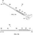
- FIG. 3Ais an isometric view of a preferred embodiment.
- FIG. 3Bis a side view of the preferred embodiment of FIG. 3A .
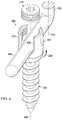
- FIG. 4is an isometric view of the preferred embodiment of FIG. 3A engaged with a tuliped pedicle screw.
- FIG. 5is a side view of an alternate preferred embodiment.
- FIG. 6is a side view of an alternate preferred embodiment.
- FIG. 7is a side view of an alternate preferred embodiment.
- FIG. 8is a side view of an alternate preferred embodiment.
- pedicle screw removal tool 300is a generally tapered cylindrical shaft comprising lower section 302 integrally formed with neck 304 .
- Neck 304is integrally formed with handle 306 .
- Tip 308is integrally formed with lower section 302 opposite neck 304 .
- Head 310is integrally formed with handle 306 opposite neck 304 .
- Torque imposing tool 313is removably attached to the head.
- the torque imposing toolmay be, for example, a ratchet adaptor which applies torque in only one rotational direction.
- the torque imposing toolcan be a simple crescent wrench.
- the torque imposing toolcan be a torque wrench indicating the amount of torque applied to prevent shearing of the pedicle screw shaft.
- Lower section 302is axially aligned with neck 304 .
- Neck 304is axially aligned with handle 306 .
- Handle 306is axially aligned with head 310 .
- Lower section 302 , neck 304 , handle 306 , and head 310all share central longitudinal axis 312 .
- Tip 308is generally “L” shaped formed by prong 314 .
- Prong 314extends from tip 308 generally perpendicular to lower section 302 .
- pedicle screw removal tool 300is constructed of surgical grade stainless steel.
- the overall length of pedicle screw removal tool 300can range from approximately eight to twelve inches depending on desired use.
- Prong 314generally ranges from 1 ⁇ 8 to 1 ⁇ 2 inch in diameter.
- the length of prong 314ranges from approximately 1 ⁇ 2 to one inch.
- Lower section 302ranges in length from approximately three to five inches.
- Lower section 302generally ranges from 1 ⁇ 8 to 1 ⁇ 2 inch in diameter.
- the length of neck 304ranges from approximately one to two inches.
- Neck 304is a generally frustoconical shape with an increasing diameter from a range of 1 ⁇ 8 to 1 ⁇ 2 inch in diameter at the connection of neck 304 to lower section 302 to a range of 1 ⁇ 2 inch to 3 ⁇ 4 inch in diameter at the connection of neck 304 to handle 306 .
- Handle 306ranges in length from approximately three to four inches. Handle 306 generally ranges from 1 ⁇ 2 to 3 ⁇ 4 inch in diameter. In an alternate embodiment, handle 306 may include serrations 316 . Head 310 ranges in length from approximately 1 ⁇ 2 to one inch. Head 310 has a generally square cross-section width a width that ranges from approximately 1 ⁇ 2 to 3 ⁇ 4 of an inch. In alternate embodiments, head 310 may have other polygonal cross-sectional shapes suitable for attachment of the torque imposing tool.
- pedicle screw removal tool 300can be used to remove tuliped pedicle screw.
- end cap 216is removed.
- stability rod 222is removed. Removal of additional tissue surrounding body 204 of pedicle screw 200 is then accomplished.
- Tip 308is inserted into channel 206 such that prong 314 is adjacent blades 208 and 210 .
- Longitudinal axis 312 of pedicle screw removal tool 300is positioned generally coplanar and parallel with longitudinal axis 226 of threaded section 202 .
- Longitudinal axis 312 of pedicle removal tool 300is generally positioned offset from longitudinal axis 226 of threaded section 202 such that the axes are not axially aligned.
- End cap 216is reengaged with body 204 to secure tip 308 to pedicle screw 200 .
- end cap 216remains disengaged from body 204 .
- tip 308is inserted into channel 206 from the side and underneath end cap 216 .
- Pedicle screw removal tool 300is rotated in direction 228 around pedicle screw 200 , generally counter-clockwise, to unscrew pedicle screw 200 from the bone. Rotation of pedicle screw removal tool 300 can be accomplished by use of handle 306 or, if necessary, a torque producing tool such as a ratchet attached to head 310 .
- pedicle screw removal tool 300eliminates the need to locate a matching removal tool for the pedicle screw regardless of whether or not the socket has been compromised. This procedure improves the speed and accuracy of pedicle screw removal as time is not wasted locating the proper sized tool, or fabricating custom tools. Further, safety is improved by reducing time required attending to unnecessary tissue damage and contamination.
- Pedicle screw removal tool 500is a generally cylindrical shaft comprising lower section 502 integrally formed with and connected to neck 504 .
- Neck 504is integrally formed with and connected to handle 106 .
- Neck 504radially expands from lower section 502 to handle 506 .
- Tip 508is integrally formed with and connected to lower section 502 opposite neck 504 .
- Head 510is integrally formed with and connected to handle 506 opposite neck 504 .
- Lower section 502is axially aligned with neck 504 .
- Neck 504is axially aligned with handle 506 .
- Handle 506is axially aligned with head 510 .
- Handle 506further includes opposing members 514 and 515 .
- Tip 508is generally “L” shaped formed by prong 516 .
- Prong 516extends from tip 508 generally perpendicular to lower section 502 .
- pedicle screw removal tool 500is constructed of surgical grade steel.
- the overall length of pedicle screw removal tool 500can range from approximately eight to twelve inches depending on desired use.
- Prong 516generally ranges from 1 ⁇ 8 to 1 ⁇ 2 inch in diameter.
- the length of prong 516ranges from approximately 1 ⁇ 2 to one inch.
- Lower section 502ranges in length from approximately three to five inches.
- Lower section 502generally ranges from 1 ⁇ 8 to 1 ⁇ 2 inch in diameter.
- the length of neck 504ranges from approximately one to two inches.
- Neck 504is a generally frustoconical shape with an increasing diameter from a range of 1 ⁇ 8 to 1 ⁇ 2 inch in diameter at the connection of neck 504 to lower section 502 to a range of 1 ⁇ 2 inch to 3 ⁇ 4 inch in diameter at the connection of neck 504 to handle 506 .
- Handle 506ranges in length from approximately three to four inches. Handle 506 generally ranges from 1 ⁇ 2 to 3 ⁇ 4 inch in diameter. Members 514 and 515 are generally cylindrical (however, other cross-sections are envisioned), are axially aligned, and extend from handle 506 generally perpendicular to handle 506 . Members 514 and 515 each range in length from approximately one and 1 ⁇ 2 to two inches. Members 514 and 515 generally range from 1 ⁇ 2 to 3 ⁇ 4 inch in diameter. Head 510 ranges in length from approximately 1 ⁇ 2 to one inch. Head 510 has a generally square cross-section width a width that ranges from approximately 1 ⁇ 2 to 3 ⁇ 4 of an inch. In alternate embodiments, head 510 may have other polygonal cross-sectional shapes suitable for attachment of a torque producing tool.
- members 514 and 515may be used to assist in the rotation of pedicle screw removal tool 500 in order to remove tuliped pedicle screws.
- Pedicle screw removal tool 600is a generally tapered cylindrical shaft comprising an angled lower section 602 integrally formed with neck 604 .
- Neck 604is integrally formed with handle 606 .
- Tip 608is integrally formed with lower section 602 opposite neck 604 .
- Head 610is integrally formed with handle 606 opposite neck 604 .
- Lower section 302extends at angle 614 from neck 604 .
- Neck 604is axially aligned with handle 606 .
- Handle 606is axially aligned with head 610 .
- Neck 604 , handle 606 , and head 610all share central longitudinal axis 612 .
- Tip 608is generally “L” shaped formed by prong 616 .
- Prong 616extends from tip 608 generally perpendicular to longitudinal axis 612 . Longitudinal axis 612 intersects prong 616 .
- pedicle screw removal tool 600is constructed of surgical grade stainless steel.
- the overall length of pedicle screw removal tool 600can range from approximately eight to twelve inches depending on desired use.
- Prong 616generally ranges from 1 ⁇ 8 to 1 ⁇ 2 inch in diameter.
- the length of prong 616ranges from approximately 1 ⁇ 2 to one inch.
- Lower section 602ranges in length from approximately three to five inches.
- Lower section 602generally ranges from 1 ⁇ 8 to 1 ⁇ 2 inch in diameter.
- Angle 614ranges from approximately 15° to 45°.
- the length of neck 604ranges from approximately one to two inches.
- Neck 604is a generally frustoconical shape with an increasing diameter from a range of 1 ⁇ 8 to 1 ⁇ 2 inch in diameter at the connection of neck 604 to lower section 602 to a range of 1 ⁇ 2 inch to 3 ⁇ 4 inch in diameter at the connection of neck 604 to handle 606 .
- Handle 606ranges in length from approximately three to four inches. Handle 606 generally ranges from 1 ⁇ 2 to 3 ⁇ 4 inch in diameter.
- Head 610ranges in length from approximately 1 ⁇ 2 to one inch. Head 610 has a generally square cross-section width a width that ranges from approximately 1 ⁇ 2 to 3 ⁇ 4 of an inch. In alternate embodiments, head 610 may have other polygonal cross-sectional shapes suitable for attachment of a torque producing tool.
- Pedicle screw removal tool 700is a generally tapered cylindrical shaft comprising lower section 702 integrally formed with and connected to neck 704 .
- Neck 704is integrally formed with and connected to handle 706 .
- Tip 708is integrally formed with and connected to lower section 702 opposite neck 704 .
- Head 710is integrally formed with and connected to handle 706 opposite neck 704 .
- Lower section 702is axially aligned with neck 704 .
- Neck 704is axially aligned with handle 706 .
- Handle 706is axially aligned with head 710 .
- Lower section 702 , neck 704 , handle 706 , and head 710all share longitudinal axis 712 .
- Tip 708is generally “T” shaped formed by prongs 714 and 715 .
- Prongs 714 and 715are axially aligned and extend from tip 708 generally perpendicular to lower section 702 .
- pedicle screw removal tool 700is constructed of surgical grade stainless steel.
- the overall length of pedicle screw removal tool 700can range from approximately eight to twelve inches depending on intended use.
- Prong 714 and 715generally range from 1 ⁇ 8 to 1 ⁇ 2 inch in diameter.
- the length of each prong 714 and 715ranges from approximately 1 ⁇ 4 to 1 ⁇ 2 inch.
- Lower section 702ranges in length from approximately three to five inches.
- Lower section 702generally ranges from 1 ⁇ 8 to 1 ⁇ 2 inch in diameter.
- the length of neck 704ranges from approximately one to two inches.
- Neck 704generally expands from a range of 1 ⁇ 8 to 1 ⁇ 2 inch in diameter at the connection of neck 704 to lower section 702 to a range of 1 ⁇ 2 inch to 3 ⁇ 4 inch in diameter at the connection of neck 704 to handle 706 .
- Handle 706ranges in length from approximately three to four inches. Handle 706 generally ranges from 1 ⁇ 2 to 3 ⁇ 4 inch in diameter. Head 710 ranges in length from approximately 1 ⁇ 2 to one inch. Head 710 has a generally square cross-section width a width that ranges from approximately 1 ⁇ 2 to 3 ⁇ 4 of an inch. In alternate embodiments, head 710 may have other polygonal cross-sectional shapes suitable for attachment of a torque producing tool.
- Pedicle screw removal tool 800is a generally tapered cylindrical shaft comprising a offset lower section 802 integrally formed with neck 804 .
- Neck 804is integrally formed with handle 806 .
- Tip 808is integrally formed with lower section 802 opposite neck 804 .
- Head 810is integrally formed with handle 806 opposite neck 804 .
- Neck 804is axially aligned with handle 806 .
- Handle 806is axially aligned with head 810 .
- Neck 804 , handle 806 , and head 810all share central longitudinal axis 812 .
- Lower section 802comprises segments 818 and 820 .
- Segment 818is generally parallel with longitudinal axis 812 and connects segment 820 to tip 808 .
- Segment 820extends generally perpendicular to longitudinal axis 812 from neck 804 .
- Prong 816extends from segment 818 generally perpendicular to longitudinal axis 812 .
- Longitudinal axis 812intersects prong 816 .
- pedicle screw removal tool 800is constructed of surgical grade stainless steel.
- the overall length of pedicle screw removal tool 800can range from approximately eight to twelve inches depending on desired use.
- the length of prong 816ranges from approximately 1 ⁇ 2 to one inch.
- Prong 816generally ranges from 1 ⁇ 8 to 1 ⁇ 2 inch in diameter.
- Lower section 802ranges in length from approximately three to five inches.
- Lower section 802generally ranges from 1 ⁇ 8 to 1 ⁇ 2 inch in diameter.
- Segment 820ranges in length from approximately 1 ⁇ 2 to one inch. Segment 820 generally ranges from 1 ⁇ 8 to 1 ⁇ 2 inch in diameter.
- the length of neck 804ranges from approximately one to two inches.
- Neck 804is a generally frustoconical shape with an increasing diameter from a range of 1 ⁇ 8 to 1 ⁇ 2 inch in diameter at the connection of neck 804 to lower section 802 to a range of 1 ⁇ 2 inch to 3 ⁇ 4 inch in diameter at the connection of neck 804 to handle 806 .
- Handle 806ranges in length from approximately three to four inches. Handle 806 generally ranges from 1 ⁇ 2 to 3 ⁇ 4 inch in diameter.
- Head 810ranges in length from approximately 1 ⁇ 2 to one inch. Head 810 has a generally square cross-section width a width that ranges from approximately 1 ⁇ 2 to 3 ⁇ 4 of an inch. In alternate embodiments, head 810 may have other polygonal cross-sectional shapes suitable for attachment of a torque producing tool.
- Pedicle screw removal tools 600 , 700 , and 800can each be used to remove any size tuliped pedicle screw.
- end cap 216is removed.
- Rod 222is removed.
- Tissue surrounding body 204 of the pedicle screwis removed.
- tip 608is inserted into channel 206 such that prong 616 is adjacent blades 208 and 210 .
- tip 708is inserted into channel 206 such that prongs 714 and 715 are adjacent blades 208 and 210 .
- tip 808is inserted into channel 206 such that prong 816 is adjacent blades 208 and 210 .
- longitudinal axis 612 , 712 , or 812is positioned generally coaxial with longitudinal axis 226 of threaded section 202 .
- the pedicle screw removal toolis rotated, generally counter-clockwise, to dislodge pedicle screw 200 from its attachment to the bone. Rotation of the pedicle screw removal tool can be accomplished by hand using the handle or, if necessary, a torque producing tool such as a wrench or ratchet can be attached to the head.
Landscapes
- Health & Medical Sciences (AREA)
- Orthopedic Medicine & Surgery (AREA)
- Neurology (AREA)
- Life Sciences & Earth Sciences (AREA)
- Surgery (AREA)
- Heart & Thoracic Surgery (AREA)
- Engineering & Computer Science (AREA)
- Biomedical Technology (AREA)
- Nuclear Medicine, Radiotherapy & Molecular Imaging (AREA)
- Medical Informatics (AREA)
- Molecular Biology (AREA)
- Animal Behavior & Ethology (AREA)
- General Health & Medical Sciences (AREA)
- Public Health (AREA)
- Veterinary Medicine (AREA)
- Surgical Instruments (AREA)
Abstract
Description
Claims (12)
Priority Applications (3)
| Application Number | Priority Date | Filing Date | Title |
|---|---|---|---|
| US15/344,152US10820936B2 (en) | 2016-11-04 | 2016-11-04 | Pedicle screw removal tool and method of use |
| PCT/US2017/014953WO2018084886A1 (en) | 2016-11-04 | 2017-01-25 | Pedicle screw removal tool and method of use |
| US16/949,562US11534223B2 (en) | 2016-11-04 | 2020-11-03 | Pedicle screw removal tool and method of use |
Applications Claiming Priority (1)
| Application Number | Priority Date | Filing Date | Title |
|---|---|---|---|
| US15/344,152US10820936B2 (en) | 2016-11-04 | 2016-11-04 | Pedicle screw removal tool and method of use |
Related Child Applications (1)
| Application Number | Title | Priority Date | Filing Date |
|---|---|---|---|
| US16/949,562Continuation-In-PartUS11534223B2 (en) | 2016-11-04 | 2020-11-03 | Pedicle screw removal tool and method of use |
Publications (2)
| Publication Number | Publication Date |
|---|---|
| US20180125559A1 US20180125559A1 (en) | 2018-05-10 |
| US10820936B2true US10820936B2 (en) | 2020-11-03 |
Family
ID=62065252
Family Applications (1)
| Application Number | Title | Priority Date | Filing Date |
|---|---|---|---|
| US15/344,152Active2037-12-16US10820936B2 (en) | 2016-11-04 | 2016-11-04 | Pedicle screw removal tool and method of use |
Country Status (2)
| Country | Link |
|---|---|
| US (1) | US10820936B2 (en) |
| WO (1) | WO2018084886A1 (en) |
Cited By (4)
| Publication number | Priority date | Publication date | Assignee | Title |
|---|---|---|---|---|
| USD939082S1 (en)* | 2020-07-30 | 2021-12-21 | Orthopedic Renovation Technologies, Llc | Pedicle screw removal tool |
| USD956233S1 (en)* | 2020-04-24 | 2022-06-28 | Solco Biomedical Co., Ltd. | Cervical screw |
| US11534223B2 (en) | 2016-11-04 | 2022-12-27 | Orthopedic Renovation Technologies, Llc | Pedicle screw removal tool and method of use |
| US20230346445A1 (en)* | 2022-05-01 | 2023-11-02 | Arizona Board Of Regents On Behalf Of The University Of Arizona | Cannulated bone screw extraction device and methods of use thereof |
Families Citing this family (3)
| Publication number | Priority date | Publication date | Assignee | Title |
|---|---|---|---|---|
| US11925393B2 (en)* | 2019-06-28 | 2024-03-12 | K2M, Inc. | Pedicle screw rasp system and adjuster |
| US11318590B2 (en) | 2019-07-17 | 2022-05-03 | Snap-On Incorporated | Tool extension |
| CN116058949A (en)* | 2022-12-26 | 2023-05-05 | 上海交通大学医学院附属瑞金医院卢湾分院 | A general-purpose pedicle screw extractor |
Citations (69)
| Publication number | Priority date | Publication date | Assignee | Title |
|---|---|---|---|---|
| US1741810A (en)* | 1927-08-22 | 1929-12-31 | Bidal Paul | Telescopic socket wrench |
| US1775402A (en)* | 1925-01-26 | 1930-09-09 | Husky Corp | Wrench outfit |
| US1835315A (en)* | 1930-06-30 | 1931-12-08 | John L Mclay | Speed wrench |
| US2530914A (en)* | 1947-04-15 | 1950-11-21 | Jesse W Simmons | Screw-eye wrench |
| US2697370A (en)* | 1951-09-04 | 1954-12-21 | Linzy W Brooks | Ratchet type socket wrench |
| US2814322A (en)* | 1955-01-06 | 1957-11-26 | Kupfrian Mfg Corp | Flexible shaft hand tool |
| US3882753A (en)* | 1973-10-18 | 1975-05-13 | Charles R Svensen | Speed wrench tool |
| US3972252A (en)* | 1976-01-12 | 1976-08-03 | Hunter John K | Top turn ratchet |
| US4334445A (en)* | 1979-03-19 | 1982-06-15 | R. T. Tool Co. Ltd. | Z Style speed wrench |
| FR2650173A1 (en) | 1989-07-26 | 1991-02-01 | Jbs Sa | METHOD AND DEVICE FOR RECOVERING, FIXING, COMPRESSION, ELONGATION OF RACHIS |
| FR2659546A1 (en) | 1990-03-19 | 1991-09-20 | Lapresle Philippe | Device for adjustable fixation of spinal osteosynthesis rods |
| US5148724A (en)* | 1991-06-13 | 1992-09-22 | Rexford Gary R | Ratchet wrench and socket apparatus |
| USD334516S (en)* | 1991-05-22 | 1993-04-06 | Yuji Tsunoda | Wrench |
| WO1994010944A1 (en) | 1992-11-09 | 1994-05-26 | Sofamor, S.N.C. | Apparatus and method for spinal fixation |
| DE4238339C2 (en) | 1992-11-13 | 1994-10-06 | Peter Brehm | Pedicle screw and holding hook for fixing a stiffening rod and instruments for adjusting and attaching the stiffening rod to the pedicle screw or holding hook |
| WO1995014437A1 (en) | 1993-11-25 | 1995-06-01 | Sofamor Danek Group, Inc. | Implant for an osteosynthesis device, particularly for the spine, and positioning instrument therefor |
| US5536268A (en) | 1992-12-23 | 1996-07-16 | Plus Endoprothetik Ag | System for osteosynthesis at the vertebral column, connecting element for such a system and tool for its placement and removal |
| EP0571619B1 (en) | 1991-12-12 | 1997-04-09 | JBS, Société Anonyme | Devices for straightening, clamping, compressing and stretching the spine |
| US5899901A (en)* | 1991-05-18 | 1999-05-04 | Middleton; Jeffrey Keith | Spinal fixation system |
| US5950507A (en)* | 1997-09-11 | 1999-09-14 | Wolfe; James P. | Socket adapter for powered drills and method of use |
| FR2778089A1 (en) | 1998-04-30 | 1999-11-05 | Dimso Sa | SPINAL OSTEOSYNTHESIS SYSTEM WITH FLANGE AND LATCH |
| US6089128A (en)* | 1998-10-05 | 2000-07-18 | Kopyless; Patrick | Wrench for inaccessible fastener |
| DE10005386A1 (en) | 2000-02-07 | 2001-08-09 | Ulrich Gmbh & Co Kg | Pedicle screw for spinal implants takes round bar whose longitudinally rotating shoe notchably accepts notch-legged clip for bar. |
| US6286396B1 (en)* | 1998-06-01 | 2001-09-11 | Mark P. Johnson | Socket ratchet and extension handle |
| US6427564B1 (en)* | 2001-02-16 | 2002-08-06 | Willie J. Nelson | Socket hand grip device |
| US20030216743A1 (en)* | 2002-05-16 | 2003-11-20 | Keith Hoffman | Bone anchor implantation device |
| US20030217623A1 (en)* | 2002-05-24 | 2003-11-27 | Brown David H. | Skateboard tool kit |
| US20050140062A1 (en)* | 2003-12-24 | 2005-06-30 | Aisin Takaoka, Co., Ltd. | Method of removing molded article and apparatus for same |
| US20050149052A1 (en) | 2003-12-31 | 2005-07-07 | Meek Christopher M. | Offset orthopaedic driver and method |
| US20050273167A1 (en)* | 2004-06-02 | 2005-12-08 | Triplett Daniel J | Surgical measurement and resection framework |
| US20080154280A1 (en)* | 2006-12-22 | 2008-06-26 | Joerg Schumacher | Surgical instrument and osteosynthesis device |
| US7470279B2 (en) | 2004-02-27 | 2008-12-30 | Jackson Roger P | Orthopedic implant rod reduction tool set and method |
| US20090187194A1 (en)* | 2008-01-17 | 2009-07-23 | Hamada James S | One step entry pedicular preparation device and disc access system |
| US20090217789A1 (en)* | 2008-03-03 | 2009-09-03 | Pi-Hsia Chang | Ratchet control structure |
| US20090248088A1 (en) | 2008-03-28 | 2009-10-01 | Lutz Biedermann | Bone anchoring device |
| US7677140B2 (en)* | 2005-12-14 | 2010-03-16 | Ricky Eugene Hull | Tool having a telescoping handle |
| WO2011133160A1 (en) | 2010-04-23 | 2011-10-27 | Synthes Usa, Llc | Spinal surgery instrument sets and methods |
| US8065938B1 (en)* | 2006-04-10 | 2011-11-29 | Kravitch Nick C | Interchangable extension tool for performing operations in limited space work areas |
| US8117951B2 (en)* | 2009-01-16 | 2012-02-21 | Accu-Sort Systems, Inc. | Double flex wrench |
| WO2012057386A1 (en) | 2010-10-28 | 2012-05-03 | 주식회사 디오메디칼 | Driver for fixing pedicle screw |
| US8202303B2 (en) | 2008-05-13 | 2012-06-19 | Spinelab Ag | Pedicle screw with a closure device |
| US8414628B2 (en) | 2006-10-26 | 2013-04-09 | Warsaw Orthopedic, Inc. | Bone screw |
| US20130090698A1 (en)* | 2011-10-07 | 2013-04-11 | Regents Of The University Of Minnesota | Stripped pedicle screw driver bit |
| USD680396S1 (en)* | 2011-07-15 | 2013-04-23 | Hsiang Jih Hardware Ent. Co., Ltd. | Key wrench |
| US8469960B2 (en) | 2007-10-23 | 2013-06-25 | Alphatec Spine, Inc. | Systems and methods for spinal fixation |
| CN203226891U (en) | 2013-02-01 | 2013-10-09 | 史亚民 | General pedicle screw wrench |
| US20130331892A1 (en) | 2010-04-23 | 2013-12-12 | Joseph Peterson | Minimally invasive instrument set, devices and related methods |
| US8617210B2 (en) | 2003-12-16 | 2013-12-31 | Depuy Spine, Sarl | Percutaneous access devices and bone anchor assemblies |
| US20140026724A1 (en)* | 2012-07-30 | 2014-01-30 | Apex Brands, Inc. | Hex wrench tool handle |
| US8709015B2 (en)* | 2008-03-10 | 2014-04-29 | DePuy Synthes Products, LLC | Bilateral vertebral body derotation system |
| WO2014142797A1 (en) | 2013-03-12 | 2014-09-18 | Jean-Pierre Mobasser | Awl-tipped pedicle screw and method of implanting same |
| US20140288567A1 (en)* | 2013-03-15 | 2014-09-25 | Royal Oak Industries | Pedicle screw driver |
| US8845649B2 (en) | 2004-09-24 | 2014-09-30 | Roger P. Jackson | Spinal fixation tool set and method for rod reduction and fastener insertion |
| US8852239B2 (en) | 2013-02-15 | 2014-10-07 | Roger P Jackson | Sagittal angle screw with integral shank and receiver |
| WO2014204076A1 (en) | 2013-06-19 | 2014-12-24 | 고려대학교 산학협력단 | Pedicle screw cap insertion device |
| US20150066042A1 (en)* | 2012-01-25 | 2015-03-05 | Spinal Usa, Inc. | Minimally invasive devices and methods for delivering fixation devices and implants into a spine |
| US8986349B1 (en) | 2009-11-11 | 2015-03-24 | Nuvasive, Inc. | Systems and methods for correcting spinal deformities |
| US9033988B2 (en)* | 2005-02-23 | 2015-05-19 | Pioneer Surgical Technology, Inc. | Minimally invasive surgical system |
| CN204446088U (en) | 2014-12-31 | 2015-07-08 | 天津正天医疗器械有限公司 | Device spanner is got for holding in orthopedic spinal nail-stick system |
| US9101416B2 (en) | 2003-01-24 | 2015-08-11 | DePuy Synthes Products, Inc. | Spinal rod approximator |
| US9125694B2 (en) | 2013-05-06 | 2015-09-08 | Life Spine, Inc. | Systems and methods for spinal rod insertion and reduction |
| US9198698B1 (en) | 2011-02-10 | 2015-12-01 | Nuvasive, Inc. | Minimally invasive spinal fixation system and related methods |
| US9241738B2 (en) | 2009-11-23 | 2016-01-26 | Rolix Holdings, Llc | CAM lock pedicle screw |
| US20160074075A1 (en) | 2013-09-01 | 2016-03-17 | Carbofix In Orthopedics Llc | Composite material spinal implant |
| US9289249B2 (en) | 2013-03-14 | 2016-03-22 | DePuy Synthes Products, Inc. | Bone anchors and surgical instruments with integrated guide tips |
| US9295500B2 (en) | 2013-06-12 | 2016-03-29 | Spine Wave, Inc. | Screw driver with release for a multiaxial bone screw |
| US9295501B2 (en) | 2011-08-02 | 2016-03-29 | Blackstone Medical, Inc. | Bayonet counter-torque wrench |
| US9326798B2 (en) | 2008-03-10 | 2016-05-03 | DePuy Synthes Products, Inc. | Derotation instrument with reduction functionality |
| US20170129078A1 (en)* | 2016-09-26 | 2017-05-11 | C3, Llc | Wrench for eye socket fastener |
- 2016
- 2016-11-04USUS15/344,152patent/US10820936B2/enactiveActive
- 2017
- 2017-01-25WOPCT/US2017/014953patent/WO2018084886A1/ennot_activeCeased
Patent Citations (70)
| Publication number | Priority date | Publication date | Assignee | Title |
|---|---|---|---|---|
| US1775402A (en)* | 1925-01-26 | 1930-09-09 | Husky Corp | Wrench outfit |
| US1741810A (en)* | 1927-08-22 | 1929-12-31 | Bidal Paul | Telescopic socket wrench |
| US1835315A (en)* | 1930-06-30 | 1931-12-08 | John L Mclay | Speed wrench |
| US2530914A (en)* | 1947-04-15 | 1950-11-21 | Jesse W Simmons | Screw-eye wrench |
| US2697370A (en)* | 1951-09-04 | 1954-12-21 | Linzy W Brooks | Ratchet type socket wrench |
| US2814322A (en)* | 1955-01-06 | 1957-11-26 | Kupfrian Mfg Corp | Flexible shaft hand tool |
| US3882753A (en)* | 1973-10-18 | 1975-05-13 | Charles R Svensen | Speed wrench tool |
| US3972252A (en)* | 1976-01-12 | 1976-08-03 | Hunter John K | Top turn ratchet |
| US4334445A (en)* | 1979-03-19 | 1982-06-15 | R. T. Tool Co. Ltd. | Z Style speed wrench |
| FR2650173A1 (en) | 1989-07-26 | 1991-02-01 | Jbs Sa | METHOD AND DEVICE FOR RECOVERING, FIXING, COMPRESSION, ELONGATION OF RACHIS |
| FR2659546A1 (en) | 1990-03-19 | 1991-09-20 | Lapresle Philippe | Device for adjustable fixation of spinal osteosynthesis rods |
| US5899901A (en)* | 1991-05-18 | 1999-05-04 | Middleton; Jeffrey Keith | Spinal fixation system |
| USD334516S (en)* | 1991-05-22 | 1993-04-06 | Yuji Tsunoda | Wrench |
| US5148724A (en)* | 1991-06-13 | 1992-09-22 | Rexford Gary R | Ratchet wrench and socket apparatus |
| EP0571619B1 (en) | 1991-12-12 | 1997-04-09 | JBS, Société Anonyme | Devices for straightening, clamping, compressing and stretching the spine |
| WO1994010944A1 (en) | 1992-11-09 | 1994-05-26 | Sofamor, S.N.C. | Apparatus and method for spinal fixation |
| DE4238339C2 (en) | 1992-11-13 | 1994-10-06 | Peter Brehm | Pedicle screw and holding hook for fixing a stiffening rod and instruments for adjusting and attaching the stiffening rod to the pedicle screw or holding hook |
| US5536268A (en) | 1992-12-23 | 1996-07-16 | Plus Endoprothetik Ag | System for osteosynthesis at the vertebral column, connecting element for such a system and tool for its placement and removal |
| WO1995014437A1 (en) | 1993-11-25 | 1995-06-01 | Sofamor Danek Group, Inc. | Implant for an osteosynthesis device, particularly for the spine, and positioning instrument therefor |
| US5950507A (en)* | 1997-09-11 | 1999-09-14 | Wolfe; James P. | Socket adapter for powered drills and method of use |
| FR2778089A1 (en) | 1998-04-30 | 1999-11-05 | Dimso Sa | SPINAL OSTEOSYNTHESIS SYSTEM WITH FLANGE AND LATCH |
| US6286396B1 (en)* | 1998-06-01 | 2001-09-11 | Mark P. Johnson | Socket ratchet and extension handle |
| US6089128A (en)* | 1998-10-05 | 2000-07-18 | Kopyless; Patrick | Wrench for inaccessible fastener |
| DE10005386A1 (en) | 2000-02-07 | 2001-08-09 | Ulrich Gmbh & Co Kg | Pedicle screw for spinal implants takes round bar whose longitudinally rotating shoe notchably accepts notch-legged clip for bar. |
| US6427564B1 (en)* | 2001-02-16 | 2002-08-06 | Willie J. Nelson | Socket hand grip device |
| US20030216743A1 (en)* | 2002-05-16 | 2003-11-20 | Keith Hoffman | Bone anchor implantation device |
| US20030217623A1 (en)* | 2002-05-24 | 2003-11-27 | Brown David H. | Skateboard tool kit |
| US9101416B2 (en) | 2003-01-24 | 2015-08-11 | DePuy Synthes Products, Inc. | Spinal rod approximator |
| US8617210B2 (en) | 2003-12-16 | 2013-12-31 | Depuy Spine, Sarl | Percutaneous access devices and bone anchor assemblies |
| US20050140062A1 (en)* | 2003-12-24 | 2005-06-30 | Aisin Takaoka, Co., Ltd. | Method of removing molded article and apparatus for same |
| US20050149052A1 (en) | 2003-12-31 | 2005-07-07 | Meek Christopher M. | Offset orthopaedic driver and method |
| US7470279B2 (en) | 2004-02-27 | 2008-12-30 | Jackson Roger P | Orthopedic implant rod reduction tool set and method |
| US20050273167A1 (en)* | 2004-06-02 | 2005-12-08 | Triplett Daniel J | Surgical measurement and resection framework |
| US8845649B2 (en) | 2004-09-24 | 2014-09-30 | Roger P. Jackson | Spinal fixation tool set and method for rod reduction and fastener insertion |
| US9033988B2 (en)* | 2005-02-23 | 2015-05-19 | Pioneer Surgical Technology, Inc. | Minimally invasive surgical system |
| US7677140B2 (en)* | 2005-12-14 | 2010-03-16 | Ricky Eugene Hull | Tool having a telescoping handle |
| US8065938B1 (en)* | 2006-04-10 | 2011-11-29 | Kravitch Nick C | Interchangable extension tool for performing operations in limited space work areas |
| US8414628B2 (en) | 2006-10-26 | 2013-04-09 | Warsaw Orthopedic, Inc. | Bone screw |
| US20080154280A1 (en)* | 2006-12-22 | 2008-06-26 | Joerg Schumacher | Surgical instrument and osteosynthesis device |
| US9320550B2 (en) | 2007-10-23 | 2016-04-26 | Alphatec Spine, Inc. | Instrument for compression and distraction |
| US8469960B2 (en) | 2007-10-23 | 2013-06-25 | Alphatec Spine, Inc. | Systems and methods for spinal fixation |
| US20090187194A1 (en)* | 2008-01-17 | 2009-07-23 | Hamada James S | One step entry pedicular preparation device and disc access system |
| US20090217789A1 (en)* | 2008-03-03 | 2009-09-03 | Pi-Hsia Chang | Ratchet control structure |
| US9326798B2 (en) | 2008-03-10 | 2016-05-03 | DePuy Synthes Products, Inc. | Derotation instrument with reduction functionality |
| US8709015B2 (en)* | 2008-03-10 | 2014-04-29 | DePuy Synthes Products, LLC | Bilateral vertebral body derotation system |
| US20090248088A1 (en) | 2008-03-28 | 2009-10-01 | Lutz Biedermann | Bone anchoring device |
| US8202303B2 (en) | 2008-05-13 | 2012-06-19 | Spinelab Ag | Pedicle screw with a closure device |
| US8117951B2 (en)* | 2009-01-16 | 2012-02-21 | Accu-Sort Systems, Inc. | Double flex wrench |
| US8986349B1 (en) | 2009-11-11 | 2015-03-24 | Nuvasive, Inc. | Systems and methods for correcting spinal deformities |
| US9241738B2 (en) | 2009-11-23 | 2016-01-26 | Rolix Holdings, Llc | CAM lock pedicle screw |
| US20130331892A1 (en) | 2010-04-23 | 2013-12-12 | Joseph Peterson | Minimally invasive instrument set, devices and related methods |
| WO2011133160A1 (en) | 2010-04-23 | 2011-10-27 | Synthes Usa, Llc | Spinal surgery instrument sets and methods |
| WO2012057386A1 (en) | 2010-10-28 | 2012-05-03 | 주식회사 디오메디칼 | Driver for fixing pedicle screw |
| US9198698B1 (en) | 2011-02-10 | 2015-12-01 | Nuvasive, Inc. | Minimally invasive spinal fixation system and related methods |
| USD680396S1 (en)* | 2011-07-15 | 2013-04-23 | Hsiang Jih Hardware Ent. Co., Ltd. | Key wrench |
| US9295501B2 (en) | 2011-08-02 | 2016-03-29 | Blackstone Medical, Inc. | Bayonet counter-torque wrench |
| US20130090698A1 (en)* | 2011-10-07 | 2013-04-11 | Regents Of The University Of Minnesota | Stripped pedicle screw driver bit |
| US20150066042A1 (en)* | 2012-01-25 | 2015-03-05 | Spinal Usa, Inc. | Minimally invasive devices and methods for delivering fixation devices and implants into a spine |
| US20140026724A1 (en)* | 2012-07-30 | 2014-01-30 | Apex Brands, Inc. | Hex wrench tool handle |
| CN203226891U (en) | 2013-02-01 | 2013-10-09 | 史亚民 | General pedicle screw wrench |
| US8852239B2 (en) | 2013-02-15 | 2014-10-07 | Roger P Jackson | Sagittal angle screw with integral shank and receiver |
| WO2014142797A1 (en) | 2013-03-12 | 2014-09-18 | Jean-Pierre Mobasser | Awl-tipped pedicle screw and method of implanting same |
| US9289249B2 (en) | 2013-03-14 | 2016-03-22 | DePuy Synthes Products, Inc. | Bone anchors and surgical instruments with integrated guide tips |
| US20140288567A1 (en)* | 2013-03-15 | 2014-09-25 | Royal Oak Industries | Pedicle screw driver |
| US9125694B2 (en) | 2013-05-06 | 2015-09-08 | Life Spine, Inc. | Systems and methods for spinal rod insertion and reduction |
| US9295500B2 (en) | 2013-06-12 | 2016-03-29 | Spine Wave, Inc. | Screw driver with release for a multiaxial bone screw |
| WO2014204076A1 (en) | 2013-06-19 | 2014-12-24 | 고려대학교 산학협력단 | Pedicle screw cap insertion device |
| US20160074075A1 (en) | 2013-09-01 | 2016-03-17 | Carbofix In Orthopedics Llc | Composite material spinal implant |
| CN204446088U (en) | 2014-12-31 | 2015-07-08 | 天津正天医疗器械有限公司 | Device spanner is got for holding in orthopedic spinal nail-stick system |
| US20170129078A1 (en)* | 2016-09-26 | 2017-05-11 | C3, Llc | Wrench for eye socket fastener |
Non-Patent Citations (2)
| Title |
|---|
| CN 203226891 machine translation, Aug. 24, 2017. |
| CN 204446088 machine translation, Aug. 24, 2017. |
Cited By (4)
| Publication number | Priority date | Publication date | Assignee | Title |
|---|---|---|---|---|
| US11534223B2 (en) | 2016-11-04 | 2022-12-27 | Orthopedic Renovation Technologies, Llc | Pedicle screw removal tool and method of use |
| USD956233S1 (en)* | 2020-04-24 | 2022-06-28 | Solco Biomedical Co., Ltd. | Cervical screw |
| USD939082S1 (en)* | 2020-07-30 | 2021-12-21 | Orthopedic Renovation Technologies, Llc | Pedicle screw removal tool |
| US20230346445A1 (en)* | 2022-05-01 | 2023-11-02 | Arizona Board Of Regents On Behalf Of The University Of Arizona | Cannulated bone screw extraction device and methods of use thereof |
Also Published As
| Publication number | Publication date |
|---|---|
| WO2018084886A1 (en) | 2018-05-11 |
| US20180125559A1 (en) | 2018-05-10 |
Similar Documents
| Publication | Publication Date | Title |
|---|---|---|
| US10820936B2 (en) | Pedicle screw removal tool and method of use | |
| US11771476B2 (en) | Apparatus and method for fenestrated screw augmentation | |
| US9211149B2 (en) | Surgical apparatus | |
| US11534223B2 (en) | Pedicle screw removal tool and method of use | |
| US5941885A (en) | Tools for use in installing osteosynthesis apparatus utilizing set screw with break-off head | |
| US8454658B2 (en) | Surgical bone anchoring device and spinal column fixation system | |
| US20190350596A1 (en) | Anti-skid surgical instrument for use in preparing holes in bone tissue | |
| JP6635688B2 (en) | Medical screwdriver, method of introducing shank and pedicle screw for medical screwdriver | |
| US8470003B2 (en) | Laminoplasty plates and methods of expanding the spinal canal | |
| US10194923B2 (en) | Tool for percutaneous joint cartilage destruction and preparation for joint fusion | |
| US20070123909A1 (en) | Extractor For Broken Bone Screws | |
| CN105358080A (en) | Orthopedic implant kit | |
| US9597135B1 (en) | Bone screw inserter | |
| JPH09266917A (en) | Guide device for interbody fusion implants | |
| US20110093014A1 (en) | Rod with Removable End and Inserter Therefor | |
| EP2221015A1 (en) | Expandable Counter-torque wrench | |
| US20140207191A1 (en) | System and Method for Performing Spinal Stabilization | |
| JP2008539021A (en) | Screw extraction and insertion device | |
| US5867912A (en) | Adjustable surgical handle | |
| CN115349939B (en) | Universal nail taking complete equipment for spinal column and operation method thereof | |
| KR101451019B1 (en) | Apparatus for pedical screw cap inducer | |
| US11925393B2 (en) | Pedicle screw rasp system and adjuster | |
| US10376298B2 (en) | Medical cutting instrument | |
| WO2020128881A1 (en) | Orthopaedic tool | |
| WO2025062391A1 (en) | Dental implant removal tool |
Legal Events
| Date | Code | Title | Description |
|---|---|---|---|
| AS | Assignment | Owner name:ORTHOPEDIC RENOVATION TECHNOLOGIES, LLC, TEXAS Free format text:ASSIGNMENT OF ASSIGNORS INTEREST;ASSIGNORS:ORTIZ, RENE;ORTIZ, ALEJANDRO RENE;PADDOCK, TROY;AND OTHERS;SIGNING DATES FROM 20170131 TO 20170201;REEL/FRAME:042693/0015 | |
| STPP | Information on status: patent application and granting procedure in general | Free format text:NON FINAL ACTION MAILED | |
| STPP | Information on status: patent application and granting procedure in general | Free format text:RESPONSE TO NON-FINAL OFFICE ACTION ENTERED AND FORWARDED TO EXAMINER | |
| STPP | Information on status: patent application and granting procedure in general | Free format text:FINAL REJECTION MAILED | |
| STPP | Information on status: patent application and granting procedure in general | Free format text:DOCKETED NEW CASE - READY FOR EXAMINATION | |
| STPP | Information on status: patent application and granting procedure in general | Free format text:NON FINAL ACTION MAILED | |
| STCV | Information on status: appeal procedure | Free format text:NOTICE OF APPEAL FILED | |
| STPP | Information on status: patent application and granting procedure in general | Free format text:DOCKETED NEW CASE - READY FOR EXAMINATION | |
| STPP | Information on status: patent application and granting procedure in general | Free format text:AWAITING RESPONSE FOR INFORMALITY, FEE DEFICIENCY OR CRF ACTION | |
| FEPP | Fee payment procedure | Free format text:PETITION RELATED TO MAINTENANCE FEES GRANTED (ORIGINAL EVENT CODE: PTGR); ENTITY STATUS OF PATENT OWNER: SMALL ENTITY | |
| STPP | Information on status: patent application and granting procedure in general | Free format text:DOCKETED NEW CASE - READY FOR EXAMINATION | |
| STPP | Information on status: patent application and granting procedure in general | Free format text:NOTICE OF ALLOWANCE MAILED -- APPLICATION RECEIVED IN OFFICE OF PUBLICATIONS | |
| STPP | Information on status: patent application and granting procedure in general | Free format text:PUBLICATIONS -- ISSUE FEE PAYMENT VERIFIED | |
| STCF | Information on status: patent grant | Free format text:PATENTED CASE | |
| MAFP | Maintenance fee payment | Free format text:PAYMENT OF MAINTENANCE FEE, 4TH YR, SMALL ENTITY (ORIGINAL EVENT CODE: M2551); ENTITY STATUS OF PATENT OWNER: SMALL ENTITY Year of fee payment:4 |