US10820930B2 - Variable angle bone plate - Google Patents
Variable angle bone plateDownload PDFInfo
- Publication number
- US10820930B2 US10820930B2US15/260,588US201615260588AUS10820930B2US 10820930 B2US10820930 B2US 10820930B2US 201615260588 AUS201615260588 AUS 201615260588AUS 10820930 B2US10820930 B2US 10820930B2
- Authority
- US
- United States
- Prior art keywords
- bone
- thread
- bone plate
- region
- extends
- Prior art date
- Legal status (The legal status is an assumption and is not a legal conclusion. Google has not performed a legal analysis and makes no representation as to the accuracy of the status listed.)
- Active, expires
Links
Images


Classifications
- A—HUMAN NECESSITIES
- A61—MEDICAL OR VETERINARY SCIENCE; HYGIENE
- A61B—DIAGNOSIS; SURGERY; IDENTIFICATION
- A61B17/00—Surgical instruments, devices or methods
- A61B17/56—Surgical instruments or methods for treatment of bones or joints; Devices specially adapted therefor
- A61B17/58—Surgical instruments or methods for treatment of bones or joints; Devices specially adapted therefor for osteosynthesis, e.g. bone plates, screws or setting implements
- A61B17/68—Internal fixation devices, including fasteners and spinal fixators, even if a part thereof projects from the skin
- A61B17/80—Cortical plates, i.e. bone plates; Instruments for holding or positioning cortical plates, or for compressing bones attached to cortical plates
- A61B17/8033—Cortical plates, i.e. bone plates; Instruments for holding or positioning cortical plates, or for compressing bones attached to cortical plates having indirect contact with screw heads, or having contact with screw heads maintained with the aid of additional components, e.g. nuts, wedges or head covers
- A—HUMAN NECESSITIES
- A61—MEDICAL OR VETERINARY SCIENCE; HYGIENE
- A61B—DIAGNOSIS; SURGERY; IDENTIFICATION
- A61B17/00—Surgical instruments, devices or methods
- A61B17/56—Surgical instruments or methods for treatment of bones or joints; Devices specially adapted therefor
- A61B17/58—Surgical instruments or methods for treatment of bones or joints; Devices specially adapted therefor for osteosynthesis, e.g. bone plates, screws or setting implements
- A61B17/68—Internal fixation devices, including fasteners and spinal fixators, even if a part thereof projects from the skin
- A61B17/80—Cortical plates, i.e. bone plates; Instruments for holding or positioning cortical plates, or for compressing bones attached to cortical plates
- A61B17/8004—Cortical plates, i.e. bone plates; Instruments for holding or positioning cortical plates, or for compressing bones attached to cortical plates with means for distracting or compressing the bone or bones
- A61B17/8014—Cortical plates, i.e. bone plates; Instruments for holding or positioning cortical plates, or for compressing bones attached to cortical plates with means for distracting or compressing the bone or bones the extension or compression force being caused by interaction of the plate hole and the screws
- A—HUMAN NECESSITIES
- A61—MEDICAL OR VETERINARY SCIENCE; HYGIENE
- A61B—DIAGNOSIS; SURGERY; IDENTIFICATION
- A61B17/00—Surgical instruments, devices or methods
- A61B17/56—Surgical instruments or methods for treatment of bones or joints; Devices specially adapted therefor
- A61B17/58—Surgical instruments or methods for treatment of bones or joints; Devices specially adapted therefor for osteosynthesis, e.g. bone plates, screws or setting implements
- A61B17/68—Internal fixation devices, including fasteners and spinal fixators, even if a part thereof projects from the skin
- A61B17/80—Cortical plates, i.e. bone plates; Instruments for holding or positioning cortical plates, or for compressing bones attached to cortical plates
- A61B17/8052—Cortical plates, i.e. bone plates; Instruments for holding or positioning cortical plates, or for compressing bones attached to cortical plates immobilised relative to screws by interlocking form of the heads and plate holes, e.g. conical or threaded
- A61B17/8057—Cortical plates, i.e. bone plates; Instruments for holding or positioning cortical plates, or for compressing bones attached to cortical plates immobilised relative to screws by interlocking form of the heads and plate holes, e.g. conical or threaded the interlocking form comprising a thread
- A—HUMAN NECESSITIES
- A61—MEDICAL OR VETERINARY SCIENCE; HYGIENE
- A61B—DIAGNOSIS; SURGERY; IDENTIFICATION
- A61B17/00—Surgical instruments, devices or methods
- A61B17/56—Surgical instruments or methods for treatment of bones or joints; Devices specially adapted therefor
- A61B17/58—Surgical instruments or methods for treatment of bones or joints; Devices specially adapted therefor for osteosynthesis, e.g. bone plates, screws or setting implements
- A61B17/68—Internal fixation devices, including fasteners and spinal fixators, even if a part thereof projects from the skin
- A61B17/80—Cortical plates, i.e. bone plates; Instruments for holding or positioning cortical plates, or for compressing bones attached to cortical plates
- A61B17/8061—Cortical plates, i.e. bone plates; Instruments for holding or positioning cortical plates, or for compressing bones attached to cortical plates specially adapted for particular bones
- A—HUMAN NECESSITIES
- A61—MEDICAL OR VETERINARY SCIENCE; HYGIENE
- A61B—DIAGNOSIS; SURGERY; IDENTIFICATION
- A61B17/00—Surgical instruments, devices or methods
- A61B17/56—Surgical instruments or methods for treatment of bones or joints; Devices specially adapted therefor
- A61B17/58—Surgical instruments or methods for treatment of bones or joints; Devices specially adapted therefor for osteosynthesis, e.g. bone plates, screws or setting implements
- A61B17/68—Internal fixation devices, including fasteners and spinal fixators, even if a part thereof projects from the skin
- A61B17/84—Fasteners therefor or fasteners being internal fixation devices
- A61B17/86—Pins or screws or threaded wires; nuts therefor
- A61B17/8605—Heads, i.e. proximal ends projecting from bone
Definitions
- This disclosurerelates generally to bone fixation implants, and in particular relates to a bone plate that is configured to lockingly receive a bone screw at an angular orientation in a range of permissible angular orientations at which the bone plate can lockingly receive the bone screw.
- Bone platesare typically made from a rigid material, such as titanium, and include fixation holes that are sized to be driven through the fixation holes and into the underlying bone to secure the bone plate to the bone.
- fixation holesare sized to be driven through the fixation holes and into the underlying bone to secure the bone plate to the bone.
- One common bone screw used in such applicationis generally referred to as a compression screw.
- Compression screwshave unthreaded heads and threaded shafts. Accordingly, the compression screw can be driven through the plate fixation hole and into the underlying bone until the head applies a compression force against the bone plate toward the underlying bone.
- Another common bone screw used in such applicationsis generally referred to as a locking screw.
- Locking screwshave threaded heads and threaded shafts. Accordingly, the locking screw can be driven through the plate fixation hole and into the underlying bone until the head threadedly mates with the bone plate in the fixation hole. Thus, the head of the locking screw does not apply a compressive force against the bone plate toward the underlying bone.
- variable angle holesConventionally, locking screws were inserted through the screw hole along the central screw hole axis in order to ensure that the threaded screw head mates with the plate in the threaded fixation hole.
- bone plateshave been developed having threaded fixation holes that are configured to receive locking screws at different trajectories within a range of trajectories whereby the bone plate threadedly mates with the locking screw head in the threaded hole. While bone plates having such holes, commonly referred to as variable angle holes, have proved to be satisfactory for their intended purpose, improved variable angle holes are nevertheless desired.
- a bone platedefines an inner surface configured to face bone, and an outer surface opposite the inner surface.
- the bone platefurther includes an internal surface that extends from the outer surface to the inner surface.
- the internal surfacedefines a fixation hole that extends from the outer surface to the inner surface along a central hole axis and is sized to receive a shaft of a bone anchor that extends out with respect to a threaded head of the bone anchor along a central anchor axis.
- the bone platefurther includes at least one thread that extends from the internal surface into the fixation hole.
- the bone platefurther defines a plurality of recesses that extend into the internal surface along a radially outward direction away from the central hole axis so as to interrupt the at least one thread and divide the at least one thread into a plurality of columns of thread segments.
- the recessesextend in a direction defined from the inner surface to the outer surface.
- the at least one threadis configured to threadedly mate with the threaded head while the bone anchor is inserted into the fixation hole such that the central anchor axis is oriented at a first orientation with respect to the central hole axis, and the at least one thread is further configured to threadedly mate with the threaded head when the bone anchor is inserted into the fixation hole such that the central anchor axis is oriented at a second orientation with respect to the central hole axis that is different than the first orientation.
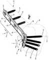
- FIG. 1is a perspective view of a bone fixation system constructed in accordance with one embodiment, including a bone plate and a plurality of fixation members that attach the bone plate to an underlying bone;
- FIG. 2Ais a perspective view of the bone plate illustrated in FIG. 1 , constructed in accordance with one embodiment
- FIG. 2Bis a perspective view of a bone plate constructed in accordance with another embodiment
- FIG. 2Cis a perspective view of a bone plate constructed in accordance with yet one embodiment
- FIG. 3Ais a perspective view of a portion of the bone plate illustrated in FIG. 1 , showing a variable angle locking hole;
- FIG. 3Bis another perspective view of a portion of the bone plate illustrated in FIG. 3A ;
- FIG. 4is a top plan view of the portion of the bone plate illustrated in FIG. 3A ;
- FIG. 5is a sectional side elevation view of the portion of the bone plate illustrated in FIG. 4 , taken along line 5 - 5 ;
- FIG. 6is a sectional side elevation view of the portion of the bone plate illustrated in FIG. 4 , taken along line 6 - 6 ;
- FIG. 7is a sectional side elevation view of the portion of the bone plate illustrated in FIG. 3A , shown with a bone anchor threadedly mated to the bone plate inside the variable angle locking hole at a first orientation;
- FIG. 8is a sectional side elevation view of the portion of the bone plate illustrated in FIG. 7 , shown with a bone anchor threadedly mated to the bone plate inside the variable angle locking hole, and oriented at a second orientation different than the first orientation;
- FIG. 9Ais a perspective view of the portion of the bone plate illustrated in FIG. 4 , but shown in accordance with an alternative embodiment
- FIG. 9Bis a sectional perspective view of the portion of the bone plate illustrated in FIG. 9A ;
- FIG. 9Cis a sectional perspective view similar to FIG. 9B , but showing the bone plate constructed in accordance with an alternative embodiment.
- a bone fixation system 20is configured to be implanted onto bone 22 so as to stabilize a first bone segment 24 with respect to a second bone segment 26 that is separated from the first bone segment 24 by a defect 28 .
- the first bone segment 24can be defined by the diaphysis of the bone, while the second bone segment 26 can be defined by the metaphysis of the bone. It should be appreciated, however, that the first and second bone segments 24 and 26 can be defined by any region of the bone 22 as desired.
- the bone 22can be any bone in the human or animal anatomy suitable for bone plate fixation.
- the bone 22can include any number of defects or bone fragments as desired that are configured for fixation using the bone fixation system 20 .
- the diaphysis of the bonecan include a plurality of bone fragments.
- the bone fixation system 20can include a bone plate 30 and a plurality of bone anchors 32 that are configured to fix the bone plate 30 to the underlying bone 22 , and in particular to each of the first and second bone segments 24 and 26 .
- the bone anchors 32include a head 33 and a shaft 35 that extends out with respect to the head 33 along a central anchor axis 53 .
- the shaft 35can extend directly from the head, or can extend from a neck that is disposed between the head 33 and the shaft 35 .
- the shaft 35can be threaded, such that the bone anchor 32 is configured as a bone screw 37 whose shaft 35 extends out relative to the head 33 along the central anchor axis 53 , which can also be referred to as a central screw axis.
- the threaded shaft 35can be configured to threadedly purchase in the underlying bone 22 .
- one or more up to all of the bone screw 37can be configured as a cortical screw whose threaded shaft 35 is designed and configured to threadedly mate to cortical bone.
- one or more of the bone screws 37can be configured as a cancellous screw whose threaded shaft 35 is designed and configured to threadedly mate to cancellous bone. It is appreciated that cancellous bone screws have threads that have a greater pitch than threads of cortical bone screws. Further, the threads of cancellous bone screws typically extend out from the shaft of the bone screw a greater distance than the threads of cortical bone screws.
- the bone plate 30defines a bone plate body 31 .
- the bone plate body 31and thus the bone plate 30 , defines an inner surface 34 configured to face the underlying bone 22 , and an outer surface 36 that is opposite the inner surface 34 along a transverse direction T.
- the bone plate 30further defines a plurality of fixation holes 38 that extend through the bone plate body 31 from the inner surface 34 to the outer surface 36 .
- the central hole axis 45can be oriented along the transverse direction T.
- the central hole axis 45can be oriented normal to each of the inner surface 34 and the outer surface 36 . It should be appreciated, of course, that the central hole axis 45 can be oriented along any suitable direction with respect to the inner surface 34 and outer surface 36 as desired.
- the fixation holes 38are sized to receive the shaft 35 of a respective one of the bone screws 37 .
- the bone screws 37 that extend through fixation holes 38are permanent bone screws, meaning that they remain after completion of the surgical procedure.
- Thisis distinguished from temporary fixation holes that, for instance, can be configured to receive temporary fixation members, such as Kirschner wires that are removed prior to completion of the surgical procedure.
- the fixation holes 38can be referred to as permanent fixation holes. Accordingly, during operation, the shaft 35 of the bone screw 37 can be inserted through a respective one of the fixation holes 38 and into the underlying bone 22 .
- the bone screw 37can then be rotated so as to cause the threaded shaft 35 to be driven into the underlying bone as the threaded shaft 35 threadedly purchases with the underlying bone.
- the threaded shaft 35can be driven into the underlying bone until the head 33 engages the bone plate 30 .
- One or more up to all of the bone screws 37can be configured as a compression screw whose head 33 is configured to bear against the bone plate 30 so as to apply a compressive force against the bone plate 30 toward the underlying bone 22 when the shaft 35 is driven further into the underlying after the head 33 has contacted the internal surface 39 .
- the shaft 35can be driven into the underlying bone a sufficient distance until the desired compressive force has been imparted onto the bone plate 30 .
- the head 33 of the compression screwis often unthreaded. Similarly, at least a portion up to an entirety of the internal surface 39 can be unthreaded.
- the bone plate 30can be spaced from the underlying bone when locked to the head 33 .
- the bone plate 30can abut the underlying bone when locked to the head 33 .
- At least a portion of the internal surface 39is typically tapered as it extends in an axially inward direction from the outer surface 36 toward the inner surface 34 .
- the internal surface 39is configured to prevent the head 33 from passing completely through the fixation hole 38 .
- the head 33can be constructed in accordance with any embodiment as described in U.S. Pat. No. 8,574,268, the disclosure of which is hereby incorporated by reference as if set forth in its entirety herein.
- the head 33can define at least one external thread that is circumferentially continuous about the central anchor axis 53 . It should be appreciated, however, that the head 33 can be alternatively constructed in any manner desired so as to threadedly mate with the internal surface 39 as described herein.
- At least one of the fixation holes 38 of the bone plate 30is configured as a variable angle locking hole 44 that is configured to threadedly mate with the bone screw 37 at different orientations of the bone screw 37 with respect to the central hole axis 45 . That is, when the fixation hole 38 is configured as a variable angle locking hole 44 , the bone plate body 31 , and thus the bone plate 30 , includes at least one thread 46 that projects out from the internal surface 39 into the fixation hole 38 . Accordingly, the internal surface 39 can define a threaded region 47 that carries the at least one thread 46 . The threaded region 47 can define at least a portion of the internal surface 39 up to an entirety of the internal surface. In one example, the thread 46 can be monolithic with the internal surface 39 .
- the bone screw 37is configured to be inserted into the fixation hole 38 such that the central anchor axis 53 is at one of a plurality of orientations with respect to the central hole axis 45 within a range of orientations at which the threaded head 33 is configured to threadedly mate with the at least one thread 46 in the fixation hole 38 .
- the bone screw 37is configured to be inserted into the fixation hole 38 such that the central anchor axis 53 is at one of a plurality of angles within a range of angles defined by the central anchor axis 53 and the central hole axis 45 at which the threaded head 33 is configured to threadedly mate with the at least one thread 46 in the fixation hole 38 .
- the range of anglescan be from approximately zero degrees to approximately 15 degrees.
- the range of anglescan define a cone of up to thirty degrees.
- the at least one thread 46is configured to threadedly mate with the threaded screw head 33 while the bone screw 37 is inserted into the fixation hole 38 such that the central anchor axis 53 is oriented at a first angle with respect to the central hole axis 45
- the at least one thread 46is further configured to threadedly mate with the threaded screw head 33 when the bone screw 37 is inserted into the fixation hole 38 such that the central anchor axis 53 is oriented at a second angle with respect to the central hole axis 45 that is different than the first angle.
- At least one or both of the first and second anglescan be non-zero angles.
- the central anchor axis 53can be coincident with the central hole axis 45 in one of the orientations in the range of orientations.
- the threads 46 and the threads of the head 33are defined prior to insertion of the bone screw 37 into the variable angle locking hole 44 . That is, the internal surface 39 is not designed or configured to cut threads into the bone screw head 33 . Similarly, the bone screw head 33 is not designed or configured to cut threads into the internal surface 39 .
- the variable angle locking hole 44is described in more detail below.
- the bone plate 30can be configured in any suitable manner as desired.
- the bone plate body 31and thus the bone plate 30 , can include a first plate portion 40 and a second plate portion 42 .
- the first plate portion 40can define a plate head portion 41 that is configured to overlie the second bone segment 26
- the second plate portion 42can be referred to as a plate shaft portion 43 that is configured to overlie the first bone segment 24 .
- Each of the plate head portion 41 and the plate shaft portion 43can include at least one up to a plurality of bone fixation holes 38 .
- bone anchors 32 that extend through respective fixation holes 38 of the plate head portion 41can be driven into the metaphysis region of the underlying bone, and bone anchors 32 that extend through respective fixation holes 38 of the plate shaft portion 43 can be driven into the diaphysis region of the underlying bone.
- the metaphysis regioncan, for instance, be defined by the distal region of the radius bone. Any one or more up to all of the fixation holes 38 of the bone plate 30 can be compression holes, locking holes, or variable angle locking holes 44 .
- all of the fixation holes 38 in the first plate portion 40are variable angle locking holes 44 .
- all of the fixation holes 38 in the second plate portion 42are compression holes configured to receive cortical bone screws.
- at least one or more up to all of the compression holescan be configured as slots that are elongate along a central longitudinal axis of the bone plate to allow for positional flexibility of the bone screw received therein.
- at least one or more up to all of the compression holescan have a circular cross-section so as to locate the position of the bone screw received therein.
- the bone plate 30can be configured to attach to any region or regions of any suitable bone in the human or animal anatomy suitable for bone plate fixation.
- the bone plate 30is illustrated in accordance with three non-limiting examples.
- the bone plate 30defines a length that extends along a longitudinal direction L, a width that is less than the length and extends along a lateral direction A that is perpendicular to the longitudinal direction L, and a thickness that is less than both the length and the width and extends along the transverse direction T that is perpendicular to each of the longitudinal direction Land the lateral direction A.
- the bone plate 30defines a distal direction from the plate shaft portion 43 to the plate head portion 41 , and a proximal direction from the plate head portion 41 to the plate shaft portion 43 .
- the distal and proximal directionscan be oriented along the longitudinal direction L.
- the bone plate 30 illustrated in FIGS. 2A-2Chas an outer perimeter 48 that is defined by the plate shaft portion 43 and the plate head portion 41 . Further, at least a portion of the plate head portion 41 of the bone plate 30 illustrated in FIGS. 2A-2C can be angled so as to extend outward as it extends in the distal direction away from the plate shaft portion 43 .
- the outer perimeter 48can be substantially Y-shaped. That is, the outer perimeter 48 can flare away outward as it extends along the distal direction from the plate shaft portion 43 .
- the width of the bone plate 30 at the plate head portion 41increases as it extends in the distal direction.
- the widthcan increase at a constant rate. Alternatively, the width can increase at an increasing rate. Alternatively still, the width can increase at a decreasing rate.
- the plate head portion 41can define a plurality of fixation holes 38 .
- One or more up to all of the fixation apertures in the plate head portion 41can be configured as variable angle locking holes 44 .
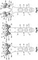
- the fixation holes 38 of the head portion 41can be arranged in a first row 50 a and a second row 50 b that is offset from the first row 50 a in the proximal direction.
- the first row 50 acan contain a greater number of fixation holes 38 than the second row 50 b .
- the first row 50 acan contain double the number of fixation apertures of the second row 50 b .
- the first row 50 acan include four fixation holes 38 , with first and second ones 38 a and 38 b of the fixation holes 38 of the first row 50 a disposed on a first side of a longitudinal centerline of the bone plate 30 , and third and fourth ones 38 c and 38 d of the fixation holes 38 of the first row 50 a disposed on a second side of the longitudinal centerline of the bone plate 30 opposite the first side.
- the first one 38 a of the fixation holes 38 of the first row 50 acan be disposed laterally outward with respect to the second one 38 b of the fixation holes 38 of the first row 50 a .
- the third one 38 c of the fixation holes 38 of the first row 50 acan be disposed laterally outward with respect to the fourth one 38 d of the fixation holes 38 of the first row 50 a .
- the central hole axis of the fourth one 38 d of the fixation holes 38 of the first row 50 acan be offset from the central hole axis of all other ones of the fixation holes 38 of the first row 50 a in the distal direction.
- the first row 50 acan include any number of fixation holes 38 as desired, arranged as desired.
- the first and second rows 50 a and 50 bcan be linear rows or can be curved as desired.
- the central hole axes of the fixation holes 38 of the fixed rowlie on a nonlinear path.
- the second row 50 bcan include likewise include any number of fixation holes 38 as desired.
- the second row 50 bcan include first and second ones 38 e and 38 f , respectively, of the fixation holes 38 .
- the central hole axes of the fixation holes 38 of the second row 50 bare spaced from the central hole axes of the fixation holes 38 of the first row 50 a in the proximal direction.
- the first one 38 e of the fixation holes 38 of the second row 50 bcan be disposed between the first and second ones 38 a and 38 b of the fixation holes 38 of the first row 50 a with respect to the lateral direction A.
- the second one 38 f of the fixation holes 38 of the second row 50 bcan be disposed between the third and fourth ones 38 c and 38 d of the fixation holes 38 of the first row 50 a with respect to the lateral direction A.
- the central hole axes 45 of one or more up to all of the fixation holes 38 a - 38 fcan be perpendicular to one or both of the bone plate surfaces 34 and 36 , or nonperpendicular to one or both of the bone plate surfaces 34 and 36 .
- the respective central hole axes 45 of the fixation holes 38 d and 38 fmay define an angle with respect to one or both of the bone plate surfaces 34 and 36 that is less than the angle defined by the central hole axes of the other fixation holes 38 a - 38 c and 38 e and the one or both of the bone plate surfaces 34 and 36 .
- the bone fixation holes 38 d and 38 fcan be said to have increased angulation with respect to the other fixation holes 38 a - 38 c and 38 e .
- the increased angulationcan allow bone screws that are inserted through the fixation holes 38 d and 38 f to be aligned with the styloid reach for fixation to the styloid reach.
- the outer perimeter 48can be substantially T-shaped. That is, the outer perimeter 48 can define opposed shoulders that flare out from the plate shaft portion 43 along the lateral direction A so as to define a proximal-most aspect of the plate head portion 41 .
- the outer perimeter 48can flare outward along the lateral direction A as it extends in the distal direction from the shoulders.
- the width of the bone plate 30 at the plate head portion 41increases as it extends in the distal direction.
- the widthcan increase at a constant rate. Alternatively, the width can increase at an increasing rate. Alternatively still, the width can increase at a decreasing rate.
- the plate head portion 41can define a plurality of fixation holes 38 . One or more up to all of the fixation apertures in the plate head portion 41 can be configured as variable angle locking holes 44 .
- the fixation holes 38 of the head portion 41can be arranged in a first row 50 a and a second row 50 b that is offset from the first row 50 a in the proximal direction.
- the first row 50 acan contain a greater number of fixation holes 38 than the second row 50 b .
- the first row 50 acan contain double the number of fixation apertures of the second row 50 b .
- the first row 50 acan include four fixation holes 38 , with first and second ones 38 a and 38 b of the fixation holes 38 of the first row 50 a disposed on a first side of a longitudinal centerline of the bone plate 30 , and third and fourth ones 38 c and 38 d of the fixation holes 38 of the first row 50 a disposed on a second side of the longitudinal centerline of the bone plate 30 opposite the first side.
- the first one 38 a of the fixation holes 38 of the first row 50 acan be disposed laterally outward with respect to the second one 38 b of the fixation holes 38 of the first row 50 a .
- the third one 38 c of the fixation holes 38 of the first row 50 acan be disposed laterally outward with respect to the fourth one 38 d of the fixation holes 38 of the first row 50 a .
- the central hole axis of the fourth one 38 d of the fixation holes 38 of the first row 50 acan be offset from the central hole axis of all other ones of the fixation holes 38 of the first row 50 a in the distal direction.
- the first row 50 acan include any number of fixation holes 38 as desired, arranged as desired.
- the first and second rows 50 a and 50 bcan be linear rows or can be curved as desired.
- the central hole axes of the fixation holes 38 of the fixed rowlie on a nonlinear path.
- the second row 50 bcan include likewise include any number of fixation holes 38 as desired.
- the second row 50 bcan include first and second ones 38 e and 38 f , respectively, of the fixation holes 38 .
- the central hole axes of the fixation holes 38 of the second row 50 bare spaced from the central hole axes of the fixation holes 38 of the first row 50 a in the proximal direction.
- the first one 38 e of the fixation holes 38 of the second row 50 bcan be disposed between the first and second ones 38 a and 38 b of the fixation holes 38 of the first row 50 a with respect to the lateral direction A.
- the second one 38 f of the fixation holes 38 of the second row 50 bcan be disposed between the third and fourth ones 38 c and 38 d of the fixation holes 38 of the first row 50 a with respect to the lateral direction A.
- the first and second ones 38 a and 38 b of the fixation holes 38 of the first row 50 a and the first one 38 e of the fixation holes 38 of the second row 50 bcan be configured to receive bone screws that are driven into one of the lunate fossa and the sigmoid notch.
- the third one 38 c of the fixation holes 38 of the first row 50 acan be configured to receive a bone screw that is driven into the scaphoid fossa.
- the fourth one 38 d of the fixation holes 38 of the first row 50 a and the second one 38 f of the fixation holes 38 of the second row 50 bcan be configured to receive bone screws that are driven into one of the styloid process. As described above with respect to FIG.
- the central hole axes 45 of one or more up to all of the fixation holes 38 a - 38 fcan be perpendicular to one or both of the bone plate surfaces 34 and 36 , or nonperpendicular to one or both of the bone plate surfaces 34 and 36 .
- the respective central hole axes 45 of the fixation holes 38 d and 38 fmay define an angle with respect to one or both of the bone plate surfaces 34 and 36 that is less than the angle defined by the central hole axes of the other fixation holes 38 a - 38 c and 38 e and the one or both of the bone plate surfaces 34 and 36 .
- the bone fixation holes 38 d and 38 fcan be said to have increased angulation with respect to the other fixation holes 38 a - 38 c and 38 e .
- the increased angulationcan allow bone screws that are inserted through the fixation holes 38 d and 38 f to be aligned with the styloid reach for fixation to the styloid reach.
- the outer perimeter 48can be forked. That is, the plate head portion 41 can define first and second arms 41 a and 41 b that extend away from the plate shaft portion 43 in the distal direction, and are spaced from each other along the lateral direction A. Respective first portions of the first and second arms 41 a and 41 b can flare away from each other along the lateral direction A as they extend away from the plate shaft portion 43 . Thus, the laterally outer perimeter 48 at the first portion of the plate head portion 41 can flare out along the lateral direction A as it extends in the distal direction. Respective second portions of the first and second arms 41 a and 41 b can flare toward from each other along the lateral direction A as they extend away from the respective first portions.
- the laterally outer perimeter 48 at the second portion of the plate head portion 41can flare in along the lateral direction A as it extends in the distal direction.
- the arms 41 a and 41 bcan be disposed on opposite sides of the longitudinal centerline of the plate 30 .
- Each of the first and second arms 41 a and 41 bcan include at least one fixation hole 38 such as a plurality of fixation holes 38 .
- One or more up to all of the fixation apertures in the plate head portion 41can be configured as variable angle locking holes 44 .
- the fixation holes 38 of each of the arms 41 a and 41 bcan be arranged in a respective first row 50 a and a second row 50 b that is offset from the first row 50 a in the proximal direction.
- the first row 50 acan be oriented substantially parallel to the outer perimeter 48 at the distal-most end of the respective arms 41 a and 41 b .
- the first row 50 acan contain double the number of fixation apertures of the second row 50 b .
- the first row 50 acan include first and second ones 38 a and 38 b of the fixation holes 38 of the first and second arms 41 a and 41 b , respectively. It should be appreciated, of course, that the first row 50 a can include any number of fixation holes 38 as desired, arranged as desired.
- the second row 50 b of each of the first and second arms 41 a and 41 bcan include likewise include any number of fixation holes 38 as desired.
- the second row 50 bcan include a respective one 38 c of the fixation holes 38 .
- the central hole axes of the fixation hole 38 of the second row 50 bare spaced from the central hole axes of the fixation holes 38 of the first row 50 a in the proximal direction.
- the respective one 38 c of the fixation holes 38 of the second row 50 bcan be disposed between the first and second ones 38 a and 38 b of the fixation holes 38 of the first row 50 a with respect to the lateral direction A.
- the first and second ones 38 a and 38 b of the fixation holes 38 of the first rows 50 acan be configured to receive bone screws that are driven into the lunate fossa and sigmoid notch.
- Bone screws inserted into the hole 38 ccan be aligned to be driven into the scaphoid fossa.
- Bone screws inserted into the hole 38 dcan be aligned to be driven into a styloid fragment.
- the fixation hole 38 a of the second row 50 bcan be configured to receive a bone screw that is driven into the lunate fossa and sigmoid notch. Bone screws can be driven into hole 38 f of the second row to reach and support a styloid fragment.
- the bone plate 30can include at least one up to a plurality of variable angle locking holes 44 .
- One of the locking holes 44will now be described in detail, it being that the description is applicable to the other locking holes of the bone plate 30 .
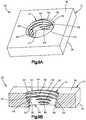
- the bone plate 30includes the internal surface 39 that extends from the inner surface 34 to the outer surface 36 .
- the internal surface 39defines the fixation hole 38 that similarly extends through the bone plate body 31 from the outer surface to the inner surface along the central hole axis 45 .
- the central hole axis 45can extend along the transverse direction T.
- the central hole axis 45can be oriented along any direction as desired, including a direction that is angularly offset with respect to the transverse direction T.
- the inner and outer surfaces 34 and 36are opposite each other along the transverse direction T.
- the transverse direction T defined by the head portion 41 of the bone plate 30may be angularly offset with respect to the transverse direction T defined by the shaft portion 43 of the bone plate 30 .
- the transverse direction Tcan be constant along an entirety of the length of the bone plate 30 .
- the fixation hole 38is sized to receive the shaft 35 of the bone anchor 32 .
- the fixation hole 38has a cross-sectional dimension that is defined from one location of the internal surface 39 to another radially opposite location of the internal surface 39 along a straight linear direction that passes through the central hole axis 45 and is perpendicular to the central hole axis 45 .
- the cross-sectional dimensiondefines a diameter of the internal surface 39 .
- the internal surface 39can extend along a circular path in cross-section along a plane that is oriented normal to the central hole axis 45 .
- the internal surface 39can define any suitable geometry as desired.
- the cross-sectional dimensionis greater than the outer diameter of the at least one thread of the bone anchor shaft 35 , such that the shaft 35 can travel through the internal surface 39 so as to extend out from the inner surface 34 and into the underlying bone.
- the variable angle locking hole 44can include the at least one thread 46 that is configured to threadedly mate with the threaded head 33 of the bone anchor 32 .
- the at least one thread 46can extend from at least a portion of the internal surface 39 into the fixation hole 38 so as to define the threaded region 47 .
- the thread 46can be monolithic with the internal surface 39 . Because the at least one thread 46 is an internal at least one thread 46 , the at least one thread 46 defines a major diameter at the interface between the at least one thread 46 and the internal surface 39 . The at least one thread 46 can extend out from the internal surface to a minor diameter that is radially inwardly spaced from the major diameter.
- the radially inward directioncan be defined as a direction toward the central hole axis 45 .
- a radially outward directionis opposite the radially inward direction.
- the radially outward directioncan be defined as a direction away from the central hole axis 45 .
- a direction normal to the central hole axis 45can be said to be radial direction.
- the threaded region 47extends along a portion of the axial length of the internal surface 39 .
- the threaded region 47can extend along an entirety of the axial length of the internal surface 39 .
- the at least one thread 46can define a thread path that is sloped with respect to a reference plane.
- the reference planecan be normal to the central hole axis 45 .
- the reference planecan be defined by the radial direction.
- the thread pathcan be defined by the minor diameter of the at least one thread 46 that defines the thread crest.
- the at least one thread 46can be a helical thread.
- the thread pathcan define a helix.
- the at least one thread 46can define a single thread.
- the at least one thread 46can include multiple threads.
- the at least one thread 46can be configured as a double lead thread or alternative multiple lead thread.
- the internal surface 39defines an axially inner end 52 that can extend to the inner surface 34 .
- the axially inner end 52can define an edge that is shared by the inner surface 34 .
- the axially inner end 52can flare radially outward as it extends in the axially inward direction toward the inner surface 34 .
- the axially inner end 52flares radially outward as it extends in the axially inward direction.
- the axially inner end 52can be defined by an undercut 56 .
- the internal surface 39can be defined by an undercut 56 that flares radially outward to the axially inner surface 34 .
- the undercut 56can flare linearly to the axially inner surface 34 .
- the axially inner end 52 of the internal surface 39can define the undercut 56 .
- at least a portion up to all of the undercut 56can be curved as it extends to the axially inner surface 34 .
- the undercut 56can extend about an entirety of the perimeter of the variable angle locking hole 44 .
- the at least one thread 46can extend radially inward from the undercut 56 .
- the undercut 56can be devoid of threads, and can be substantially smooth.
- the undercut 56can cause the internal surface 39 to avoid contact with the shaft 35 at angles between the central anchor axis 53 and the central hole axis 45 that would be prevented due to contact between the internal surface 39 and the shaft 35 without the undercut 56 .
- the undercut 56can widen the range of angles that are defined by the central anchor axis 53 and the central hole axis 45 at which the threaded head 33 is configured to threadedly mate with the at least one thread 46 in the fixation hole 38 .
- the internal surface 39defines an axially outer end 54 that is opposite the axially inner end 54 .
- the axially outer end 54can extend to the outer surface 36 .
- the axially outer end 54can define an edge that is shared by the inner surface 34 .
- the axially outer end 54can flare radially outward as it extends in an axially outward direction that is opposite the axially inward direction, and thus in a direction from the inner surface 34 toward the outer surface 36 .
- the axially outer end 54can flare radially outward as it extends in the outward direction to the outer surface 36 .
- the axially inward and axially outward directionscan be oriented along the transverse direction T, or can define an angle with respect to the transverse direction T.
- the internal surface 39can be tapered and extend along both the axially inward direction and the axially outward direction.
- the at least one thread 46can extend from a first location 46 a to a second location 46 b that is offset from the first location 46 a along the axially outward direction.
- the at least one threadterminates at the first location 46 a and the second location 46 b .
- the first location 46 acan extend to the inner end 52 of the internal surface 39 .
- the first location 46 acan extend to the inner surface 34 .
- the first location 46 acan be offset from the inner surface 34 along the axially outward direction.
- the second location 46 acan extend to the outer end 54 of the internal surface 39 .
- the first location 46 acan extend to a second region 49 of the internal surface 39 described in more detail below.
- the second location 46 bcan extend to the outer surface 36 .
- the second location 46 bcan be offset from the outer surface 36 along the axially inward direction.
- the at least one thread 46defines at least one discontinuous segment between the first location 46 a and the second location 46 b .
- the first location 46 acan be defined by the inner end 52 of the internal surface 39 .
- the first location 46 acan extend inwardly to the inner surface 34 .
- the first location 46 acan be offset from the inner surface 34 along the axially outward direction.
- the plate body 31and thus the plate 30 , can define a step 58 that projects radially outward with respect to the threaded region 47 of the internal surface 39 .
- the step 58can project radially outward from the threaded region 47 .
- the step 58can be oriented along a plane that is normal to the central hole axis 45 .
- the step 58can be sloped with respect to the plane that is normal to the central hole axis 45 .
- the step 58can be oriented along any suitable direction as desired.
- the internal surface 39can define a second region 49 that extends from the step 58 to the axially outer surface 36 .
- the axially outer end 54 of the inner surface 39can be defined by the second region 49 .
- the second region 49can be tapered radially inwardly as it extends in the axially inward direction.
- the second region 49can be tapered radially inwardly from the axially outer surface 36 to the step 58 .
- the second region 49can be conical.
- the threaded region 47 of the internal surface 39can extend from the step 58 to the axially inner surface 34 .
- the threaded region 47 of the internal surface 39can extend from the step 58 to the undercut 56 .
- the columns 62can extend from the step 58 to the axially inner surface 34 .
- the columnscan extend from the step 58 to the undercut 56 .
- the step 58can define any surface area as desired.
- the surface areacan be between approximately 1.5 mm 2 and approximately 3 mm 2 , such as approximately 2.1 mm 2 .
- the terms “approximate” and “substantially” as used herein with respect to dimensions and shapesrecognizes that manufacturing tolerances along with other factors, such as rounding, can cause variation in measurements and distances. Further, term “between” with respect to ranges of dimensions is used herein to also include the respective dimensions.
- the threaded region 47can define any suitable height as desired.
- the heightcan be measured as an offset distance from the first location 46 a of the at least one thread 46 to the second location 46 b of the at least one thread 46 along the transverse direction T.
- the heightcan be measured as an offset distance from the first location 46 a of the at least one thread 46 to the second location 46 b of the at least one thread 46 along a direction parallel to the central hole axis 45 .
- the heightcan be measured from the axially inner surface 34 to the step 58 along the transverse direction. If the bone plate 30 does not include the step 58 as illustrated in FIGS. 9A-9B , the height can be measured from the inner surface 34 to the outer surface 36 along the transverse direction T.
- the height of the threaded region 47can be between approximately 0.5 mm and approximately 3 mm, such as between approximately 1 mm and approximately 2 mm, for instance approximately 1.4 mm.
- the second region 49 of the internal surface 39can flare radially outward from the step 58 to the axially outer surface 36 .
- the second region 49 of the internal surface 39can flare linearly along a direction from the step to the axially outer surface 36 .
- at least a portion up to all of the second region 49 of the internal surface 39can be curved as it extends from the step 58 to the axially outer surface 36 .
- the threaded region 47 of the internal surface 39can be offset in the radially inward direction from the second region 49 . That is, the threaded region can be disposed between the second region 49 and the central hole axis 45 with respect to the radial direction.
- the threaded region 47can be tapered radially inwardly along its length as it extends in the axially inward direction.
- the threaded region 47 at each of the columns 62can be conical from its axially outer end to the undercut 56 , or alternatively can be conical from its axially outer end to the axially inner surface 34 if the undercut 56 is not present.
- These areascan be referred to as tapered threaded areas 51 of the threaded region 47 , and thus of the internal surface 39 .
- the tapered threaded area 51can define an axially outer end and an axially inner end.
- the axially outer end of the tapered threaded area 51can be defined by the step 58 .
- the axially outer end of the tapered threaded area 51can be defined by the axially outer surface 36 .
- the axially inner end of the tapered threaded area 51can be defined at the undercut 56 .
- the axially inner end of the tapered threaded area 51can be defined by the axially inner surface 34 .
- the conical shape of the second region 49can be concentric with the conical shape of the threaded region of the internal surface 39 .
- the undercut 56can extend out from the axially inner end of the radially inwardly tapered region of the internal surface 39 . Further, the undercut 56 can include a portion of the at least one thread 46 , and thus can define a portion of the threaded region 47 . Alternatively, the undercut 56 can be devoid of threads. In one example, one or both of the step 58 and the second region 49 of the internal surface 39 can be devoid of threads designed to purchase with the threaded head 33 of the bone anchor 32 .
- the fixation hole 38can be configured to receive the head of a compression screw, such that the head of the compression screw abuts the second region 49 and applies a compression force to the bone plate that urges the bone plate toward, for instance against, the underlying bone as the compression screw is driven into the underlying bone.
- One or both of the step 58 and the second region 49 of the internal surface 39can be said to be substantially smooth.
- the second region 49 at the step 58can define any diameter as desired.
- the diameter of the second region at the step 58can be in the range of approximately 2.5 mm and approximately 5 mm, for instance, between approximately 3 mm and approximately 4 mm, such as between approximately 3.5 mm and approximately 4 mm, and in one example can be approximately 3.7 mm.
- the diameter of the second region 49 at the stepcan also be referred to as an outer diameter of the step 58 .
- the plate body 31can define a plurality of (e.g., at least two) recesses 60 that divide at least a portion of the threaded region 47 into a plurality of (e.g., at least two) columns 62 .
- the recessesdivide the at least one thread 46 into a plurality of columns 62 of thread segments 64 that are described in more detail below.
- Opposed pairs of the columns 62can be disposed radially opposite each other through the central hole axis 45 .
- each of the recesses 60can extend through the threaded region 47 at least to the internal surface 39 along the radially outward direction away from the central hole axis 45 .
- at least a portion up to an entirety of each of the recessescan extend into the internal surface 39 along the radially outward direction away from the central hole axis 45 .
- the recesses 60can further extend radially outward through the at least one thread 46 that is carried by the internal surface 39 .
- Each of the recesses 60terminates radially at a respective recessed surface 61 of the plate body 31 .
- the recesses 60can be at least partially or fully defined by the recessed surface 61 .
- each recessed surface 61defines a radial outer perimeter of the respective recesses 60 .
- the recessed surface 61 of each of the recesses 60 between adjacent ones of the columns 62can define any suitable surface area as desired.
- the surface area of the recessed surface 61 of each of the recesses 60can be between approximately 0.5 mm 2 and approximately 4 mm 2 , such as between approximately 1 mm 2 and approximately 3 mm 2 , and in one example can be approximately 1.9 mm 2 .
- the recesses 60can have a radial depth sufficient such that the recessed surface 61 is recessed with respect to the internal surface 39 along the radially outward direction. That is, the recessed surface 61 can define a radial distance from the central hole axis 45 that is greater than the radial distance from the central hole axis 45 to the major diameter of the at least one thread 46 . Further, an entirety of the recessed surface 61 can define a curvature along a plane that is oriented normal to the central hole axis 45 from a first end of the recessed surface 61 that adjoins the internal surface 39 to a second end of the recessed surface 61 that adjoins the internal surface 39 . The curvature can be a constant curvature from the first end to the second end.
- the recessed surface 61extends along a circular path along the plane that is oriented normal to the central hole axis 45 .
- the first and second ends of an entirety of the recessed surface 61 at an entirety of the tapered threaded area 51can diverge away from each other as they adjoin the internal surface 39 .
- a straight line that extends from the first end of the recessed surface to the second end of the recessed surface at the entirety of the tapered threaded area 51can define a chord of a circle that defines the circular path of the recessed surface 61 .
- the chordcan be disposed between the center of the circle and the recessed surface 61 .
- the first and second ends of the recessed surfacecan define a circumferential length that is less than or equal to (e.g., no more than) 180 degrees of the circle that defines the circular path of the recessed surface 61 along a plane that is normal to the central hole axis 45 , along an entirety of the tapered threaded area 51 .
- the circumferential length of the recessed surface 61can decrease along the axially outward direction.
- the recessed surface 61can define a minor arc along the plane from the first end of the recessed surface 61 to the second end of the recessed surface 61 , at an entirety of the tapered threaded area 51 .
- the plate body 31can include four recesses 60 that are circumferentially spaced apart from each other.
- the plate body 31can include any number of recesses 60 , greater than one, as desired, so as to define the variable angle locking hole 44 of the type described herein.
- the respective constant distance of the recessed surfaces of each of the recesses 60can be the same as each other.
- each of the recesses 60can be substantially identical to each other.
- the recesses 60can be circumferentially equidistantly spaced from each other about the central hole axis 45 .
- the recesses 60can be circumferentially spaced from each other a variable distance about the central hole axis 45 .
- the plate body 31can include four columns 62 of thread segments 64 that are circumferentially spaced apart from each other.
- the plate body 31can include any number of columns 62 , greater than one, as desired, so as to define the variable angle locking hole 44 of the type described herein.
- the columns 62can be substantially identical to each other. Further, the columns 62 can be circumferentially equidistantly spaced from each other about the central hole axis 45 . Alternatively, the columns 62 can be circumferentially spaced from each other a variable distance about the central hole axis 45 .
- Adjacent ones of the columns 62can be separated by a common one of the recesses 60 .
- the adjacent ones of the columns 62can be referred to as circumferentially adjacent ones of the columns 62 .
- the columns 62 and recesses 60can define circumferential centerlines that extend along planes that intersect the central hole axis 45 .
- the circumferential centerlines of the columnscan be circumferentially offset from circumferential centerlines of the recesses 60 by 45 degrees.
- Each of the columns 62 of the threaded region 47includes a plurality of thread segments 64 .
- the thread segments 64can be defined by the least one thread 46 .
- the thread segments 64 of each of the columns 62are offset from each other along the transverse direction T.
- each of the columnscan define respective circumferential lengths that decrease in the axially inward direction.
- the thread segments 64 of each of the columns 62can be discontinuous with respect to the thread segments 64 of the other ones of the columns 62 at the recesses 60 .
- each of the recesses 60interrupts the at least one thread 46 and divides the at least one thread 46 into the corresponding plurality of thread segments 64 .
- Each column 62can include a plurality of the thread segments 64 .
- Each column 62can be tapered radially inwardly as it extends in the axially inward direction.
- the threaded region 47 of the internal surface 39 at each of the columns 62can lie on a conical surface.
- the thread segments 64 of each of the columns 62can thus be circumferentially offset from the thread segments 64 of the other ones of the columns 62 . Further, adjacent ones of the circumferentially spaced thread segments 64 can be separated by a common one of the recesses 60 . Thus at least one or more of the thread segments 64 up to all of the thread segments 64 are aligned with at least one other of the thread segments 64 of an adjacent one of the columns 62 along the thread path. For instance, at least one or more of the thread segments 64 up to all of the thread segments 64 are aligned with at least one other of the thread segments 64 of an adjacent one of the columns 62 along a helical path.
- each of a plurality of the thread segments 64 of a respective one of the columns 62is aligned along a thread path with 1) a first one the thread segments 64 of a first other one of the columns 62 that is adjacent the respective one of the columns 62 along a first circumferential direction, and 2) a second one the thread segments 64 of a second other one of the columns 62 that is adjacent the respective one of the columns 62 along a second circumferential direction that is opposite the first circumferential direction.
- the respective one of the columns 62is disposed circumferentially between the first other one of the columns and the second other one of the columns.
- the thread segments 64 of the respective one of the columnsis disposed between the first one of the thread segments 64 and the second one of the thread segments 64 with respect to the transverse direction.
- Each of the columns 62can define a circumferential length in a respective plane oriented normal to the central hole axis 45 .
- the circumferential length of each of the columns 62can decrease in the radially inward direction.
- the thread segments 64 of each of the columns 62are offset from each other along the transverse direction T. Further, each of the thread segments 64 defines first and second circumferentially opposed terminal ends. Each of the thread segments 64 defines a respective circumferential length from the first circumferentially terminal end to the second circumferentially terminal end.
- the circumferential lengthscan be measured at the crests of the thread segments 64 , which can be defined by the minor diameter. In one example, the circumferential lengths of the thread segments 64 decrease in the axially inward direction.
- the columns 62define at least three consecutive ones of the thread segments 64 whose circumferential lengths decrease in the axially inward direction. It can thus also be said that the circumferential lengths of the at least three consecutive ones of the thread segments 64 increase in the axially outward direction.
- the axially outermost one of the thread segments 64 of each of the columnshas a circumferential length greater than the axially innermost one of the thread segments 64 of each of the columns.
- the undercut 56can be devoid of threads and smooth. Alternatively, the undercut 56 can define at least one thread segment 64 that is consecutive with an axially innermost one of the thread segments 64 of the each of the columns 62 along the thread path.
- each of the recesses 60can extend from a respective axially first or inner terminal end to a respective opposed axially second or outer terminal end.
- the inner terminal endcan be disposed at the axially inner surface 34 .
- the inner terminal endcan be disposed at the undercut 56 .
- the undercut 56can be localized at a location aligned with the columns 62 so as to not extend circumferentially beyond the columns 62 .
- the undercut 56can extend about the entire perimeter of the variable angle locking hole 44 .
- the outer terminal endcan be spaced axially inward from the axially outer surface 36 . Accordingly, the axially outer surface 36 can define an opening 29 of the variable angle locking hole 44 .
- the opening 29thus has a continuous outer perimeter that is defined by the axially outer surface 36 of the bone plate 30 . Further, an entirety of the recessed surfaces 61 of each of the recesses 60 can be offset from the outer perimeter of the opening in the radially inward direction, that is toward the central hole axis 45 .
- the outer perimeter of the opening 29can define a circle. It should be appreciated, however, that the outer perimeter of the opening 29 can define any suitable alternative shape as desired.
- the axially outer surface 36 at the opening 29can define any suitable alternative shape as desired.
- the recesses 60can extend through the bone plate body to the axially outer surface 36 , such that the recessed surfaces partially define the outer perimeter.
- the axially outer surface 36 at the opening 29can be defined by both the internal surface 39 and the recessed surfaces 61 .
- the axially outer surface 36 at the opening 29 at locations defined by the internal surface 39can be concave to the central hole axis 45 and defined by a first curvature, and the axially outer surface 36 at the opening 29 at locations defined by the recessed surfaces 61 can be concave to the central hole axis 45 and defined by a second curvature that is greater than the first curvature.
- the outer terminal endcan be disposed between the axially inner surface 34 and the axially outer surface 36 .
- the outer terminal end of the recesses 60can be disposed in the threaded region 47 .
- a portion of the at least one threadcan be disposed between the second terminal end of the recess 60 and the axially outer surface 36 of the bone plate body 31 .
- the step 58can be disposed between the outer terminal end of the recesses 60 and the axially outer surface 36 with respect to the transverse direction T.
- the internal surface 39 at the step 58can define a constant curvature along its length.
- the constant curvaturecan, for instance, be circular.
- the internal surface 39 at the step 58can define any circumferential length as desired.
- the circumferential length of the internal surface 39 at the step 58can be in the range of approximately 5 mm and approximately 15 mm, for instance, between approximately 10 mm and approximately 11 mm, such as approximately 10.4 mm.
- the circumferential length of the internal surface 39 at the step 58can also be referred to as an inner circumference of the step 58 .
- At least a portion of the at least one thread 46has a continuous region 63 in which the at least one thread 46 extends continuously along at least one revolution about the central hole axis 45 .
- the at least one thread 46can extend continuously along a plurality of revolutions about the central hole axis 45 .
- the continuous region 63can lie on the same thread path as the thread segments 64 .
- the continuous region 63can be disposed between the outer terminal ends of the recesses 60 and the axially outer surface 36 of the bone plate 30 .
- the continuous region 63can extend from one of the columns 62 , and in particular from the axially outermost thread segment of the one of the columns 62 .
- the continuous region 63can further extend to the axially outer surface 36 or to a location that is offset from the axially outer surface 36 in the axially inward direction.
- the outer terminal ends of the recesses 60can be offset from the axially outer surface 36 in the axially inward direction a distance that is at least equal to or greater than the pitch of the at least one thread 46 .
- the continuous region 63can be disposed between the recesses 60 and the axially outer surface 36 with respect to the transverse direction T. The continuous region 63 is positioned so as to purchase with the threaded head 33 of the bone anchor 32 when the bone anchor 32 is oriented such that the angle defined by the central anchor axis 53 and the hole axis 45 are within the range of angles in which the threaded head 33 is configured to threadedly mate with the at least one thread 46 in the fixation hole 38 .
- the threaded headis configured to thrededly mate with at least a portion of the continuous region 63 of the at least one thread 46 when the bone anchor 32 is oriented such that the angle defined by the central anchor axis 53 and the hole axis 45 are within the range of angles.
- the recesses 60can be oriented in any direction as desired.
- the recesses 60can each be oriented along the transverse direction T.
- the recessed surface 61 of each of the recesses 60can be spaced from the central hole axis 45 a respective constant distance along its length from the inner terminal end to the outer terminal end. Because the internal surface 39 can be tapered radially inward as it extends in the axially inward direction, and because the recesses 60 are oriented along the transverse direction T from their inner terminal end to their outer terminal end, the radial depth of the recesses 60 can decrease as the recesses 60 extend in the axially outward direction. Further, the length of the recessed surface 61 along a respective plane oriented normal to the central hole axis 45 can decrease in the radially outward direction at the tapered threaded area 51 .
- the tapered threaded area 51 between its axially outer end and its axially inner endcan define any suitable surface area as desired.
- the surface area defined by the tapered threaded area 51can be between approximately 4.5 mm2 and approximately 9 mm2, such as between approximately 5 mm 2 and approximately 8 mm 2 , for instance between approximately 6 mm 2 and approximately 7 mm 2 , such as approximately 6.8 mm 2 .
- the plate body 31can define an interface between the axially inner end of the tapered threaded area 51 and the undercut 56 .
- the interfacecan have any suitable length as desired.
- the length of the interfacecan be between approximately 0.2 mm and approximately 0.9 mm, such as between approximately 0.3 mm and approximately 0.7 mm, such as approximately 0.5 mm.
- Fabrication of the bone plate 30can include the step of creating a through-hole through the bone plate body 31 from the axially outer surface 36 to the axially inner surface 34 .
- the creating stepcan, for instance, include the step of creating the through-hole through the bone plate body 31 so as to define an interior surface of the plate body 31 .
- the through-holecan be created such that the interior surface of the bone plate body 31 tapers radially inward toward the central hole axis 45 as it extends in the axially inward direction, as described above.
- the creating stepcan, in one example, include the step of drilling the through-hole through the bone plate body 31 .
- the drilling stepcan be performed in a single step, or in multiple steps of creating a through-hole, and then defining the through-hole to have a conical shape. Further, the drilling step can include the step of creating a counterbore so as to define the step 58 and the corresponding second region 49 as described above. However, as recognized from the description below, the bone plate can be devoid of the step 58 , such that the variable angle locking hole includes the threaded region 47 and not the second region 49 . Accordingly, the internal surface 39 can define a constant taper from the axially outer surface 36 to the undercut 56 , or to the axially inner surface 34 if the bone plate 30 does not include the undercut. The method can further include the step of creating the undercut 56 at the axially inner surface 34 . The undercut 56 can be created during the step of creating the through-hole, or after the through-hole has been created.
- the methodcan include the step of cutting the at least one thread 46 into the interior surface so as to define the internal surface 39 and the at least one thread 46 .
- the minor diameter of the at least one thread 46can be defined by the crest of the at least one thread 46
- the major diameter of the at least one threadcan be defined by the internal surface 39 .
- the threadcan define a height from the minor diameter to the major diameter along its length. In one example, the height can be constant along at least a plurality of revolutions of the at least one thread 46 about the central hole axis 45 .
- the minor diameter of the threadcan lie on a conical geometric shape.
- the heightcan increase or decrease along the length of the at least one thread 46 as the at least one thread 46 extends in the axially inward direction.
- the methodcan further include the step of creating the recesses 60 in the internal surface 39 .
- the step of creating the recesses 60can similarly create the columns 62 .
- the step of creating the recesses 60can be performed after the at least one thread is formed 46 .
- the step of creating the recesses 60can be performed prior to forming the at least one thread 46 .
- the recesses 60can be created in the interior surface to define the columns 62 , and the at least one thread 46 can then be created in the columns 62 so as to define the interior surface 39 and the at least one thread.
- each of the recesses 60defines a circumferential end that is open at the internal surface 39 .
- each of the recesses 60can be drilled into the axially inner surface 34 along the axially inward direction, such that the inner end of the recesses 60 have a radial depth that decreases as the recesses 60 extend in the axially outward direction.
- the decreasing radial depthcan be due to the conical shape of the internal surface 39 .
- the radial depth of the recesses 60can be selected so as to define the columns 62 of thread segments 64 as described above.
- the step of drilling the recesses 60can also remove material from the at least one thread 46 at a location axially outward from the outer terminal end of the recesses 60 .
- material of the bone plate body 31can be removed from the at least one thread 46 but does not extend radially through the at least one thread 46 so as to interrupt the major diameter and extend into the internal surface 39 .
- the at least one thread 46can be said to be circumferentially continuous with an increased minor diameter.
- the minor diameter at least one thread 46can thus include a plurality of sections having increased dimensions that are aligned with the respective plurality of recesses 60 along the transverse direction T.
- the at least one thread 46can be referred to as continuous with sections of increased minor diameter. Locations of the at least one whereby the major diameter of the at least one thread 46 is interrupted can be referred to herein as thread segments 64 of one of the columns 62 . Locations of the at least one thread whereby the major diameter is continuous and the minor diameter is increased can be referred to herein as a circumferentially continuous portion of the at least one thread that at least partially defines the continuous region 63 .
- the locations of the at least one thread having an increased minor diametercan be circumferentially continuous with locations of the at least one thread having an uninterrupted minor diameter so as to define the continuous region 63 that extends circumferentially at least one revolution about the central hole axis 45 .
- the increased dimensions of the minor diameterscan decrease as in the axially outward direction due to the tapered, for instance, conical, profile of the minor diameter.
- the bone plate body 31can define a height along the transverse direction T from the axially inner surface 34 to the axially innermost end of the continuous region 63 .
- the heightcan be any suitable height as desired. In one example, the height can be between approximately 1.3 mm and approximately 3 mm, including between approximately 1.75 mm and 2.5 mm, such as approximately 2.25 mm. This height can also be said to define the height of the recesses 60 along the transverse direction T. This height can also be said to define the height of the columns 62 .
- the bone plate 30is brought into proximity with the underlying bone.
- the axially inner surface 34can be brought into contact with the underlying bone, or can be spaced from the underlying bone.
- a plurality of bone anchorscan be inserted through respective bone fixation holes 38 of the bone plate 30 so as to fix the bone plate 30 to the underlying bone at opposite locations of a bone defect of the underlying bone.
- the method of fixing the bone plate 30 to the underlying bone through the variable angle locking holes 44includes the step of inserting the shaft 35 of the bone anchor 32 through the fixation hole 38 , which can be configured as the variable angle locking hole 44 , and into the underlying bone.
- the bone anchor 32can be rotated about the central anchor axis 53 so as to drive the shaft 35 into the underlying bone.
- the central anchor axis 53can define any suitable angle with respect to the central hole axis 45 within a range of angles.
- the range of anglescan extend from 0 degrees to approximately 15 degrees as defined by the central anchor axis 53 and the central hole axis 45 in any direction about the central hole axis 45 , that is along the full 360 degree circumference about the central hole axis 45 .
- the range of anglescan be achieved when bone screw fixation instrumentation, such as a drill guide, is also inserted into the fixation hole 38 .
- the range of angles of the central hole axis 45 with respect to the central anchor axis 53can define a cone about the central hole axis 45 .
- the central hole axis 45can define the axis of the cone.
- Continuing rotation of the bone anchor 32 while the angle defined by the central anchor axis 53 and the central hole axis 45 is in the range of anglescauses the threaded head 33 to advance into the variable angle locking hole 44 , such that the threaded head 33 threadedly mates with the at least one thread 46 of the variable angle locking hole 44 .
- a portion of the threaded head 33can threadedly mate with the continuous region 63 of the at least one thread 46 alone or in combination with at least one or more of the columns 62 of thread segments 64 up to all of the columns 62 of thread segments 64 .
- variable angle locking hole 44is configured to provide increased surface area contact with the head 33 of the bone anchor 32 with respect to conventional variable angle locking holes, thereby increasing the reliability of the threaded purchase between the bone plate and the bone anchor 32 . It is recognized that different angles between the central anchor axis 53 and the central hole axis 45 will cause the threaded head 33 to threadedly purchase with different locations of the at least one thread 46 with respect to the transverse direction T.
- the recesses 60assist in the ability of the bone anchor 32 to angulate with respect to the central hole axis 45 within the range of angles while threadedly purchasing with the at least one thread 46 .
- the ability of the threaded head 33 to threadedly purchase with both the columns 62 of thread segments 64 and with the continuous region 63 of the at least one thread 46can provide more reliable fixation than conventional variable angle locking holes.
- the continuous region 63can be removed while providing adequate fixation by threadedly mating the threaded head 33 with the columns 62 of thread segments 64 .
- the plate 30can be constructed in accordance with numerous examples, some of which have been described above.
- the bone platecan be devoid of the step 58 and the second region 49 of the internal surface 39 .
- the surface that previously defined the step 58 of the bone plate 30can define the axially outer surface 36 .
- the threaded region 47can extend from the axially outer surface 36 to the axially inner surface 34 .
- the tapered threaded area 51 of the threaded region 47can extend from the axially outer surface 36 to the undercut 56 .
- the tapered threaded area 51 of the threaded region 47can extend from the axially outer surface 36 to the axially inner surface 34 .
- the continuous region 63 of the at least one thread 46can extend from the columns 62 to the axially outer surface 36 .
- the axially outer end 54 of the inner surface 39can be defined by the continuous region 63 .
- the height of the bone plate 30 from the axially inner surface 34 to the axially outer surface 36 along the transverse direction Tcan be between approximately 0.5 mm and approximately 3 mm, such as between approximately 1 mm and approximately 2 mm, for instance approximately 1.4 mm.
- the bone plate 30can achieve superior fixation to the bone anchor head 33 while achieving a smaller bone plate height than conventional bone plates having variable angle locking holes.
- the height of the bone plate 30can be further reduced while achieving adequate fixation between the at least one thread 46 and the threaded head 33 .
- the at least one thread 46can be devoid of the continuous region 63 .
- the columns 62extend from the axially outer surface 36 to the axially inner surface 34 .
- the entirety of the least one threaded region 47is segmented into columns 62 of thread segments 64 .
- the tapered threaded area 51can extend from the axially outer surface 36 to the undercut 56 .
- the tapered threaded area 51can extend from the axially outer surface 36 to the axially inner surface 34 if the bone plate 30 does not include the undercut 56 .
- an entirety of the tapered threaded area 51can be divided into columns 62 by the recesses 60 .
- the outer terminal ends of the recesses 60can be offset axially inward with respect to the axially outer surface 36 .
- the outer terminal ends of the recesses 60are not offset from the axially outer surface 36 a distance such that the at least one thread can extend an entire revolution about the central hole axis 45 at a location between the recesses and the axially outer surface.
- the offset distancecan be less than the pitch of the at least one thread 46 .
- the recesses 60can extend through both the axially inner surface 34 and the axially outer surface 36 .
- the internal surface 39defines a surface area in the range of 4.0 to 6.5 mm 2 , such as approximately 6.35 mm 2 .
- the elimination of the continuous region 63 of the at least one thread 46can allow the plate 30 to have a further reduced height from the axially inner surface 34 to the axially outer surface 36 .
- the heightcan be in the range of approximately 0.5 to approximately 1 mm, such as approximately 0.75 mm. It is appreciated that in FIG.
- an entirety of the surface area of the internal surface 39is threaded with the at least one thread 46 , such that the entirety of the surface area of the tapered threaded area 51 is available for threaded purchase with the bone anchor 32 depending on the angle of the central anchor axis 53 relative to the central hole axis 45 .
Landscapes
- Health & Medical Sciences (AREA)
- Orthopedic Medicine & Surgery (AREA)
- Surgery (AREA)
- Life Sciences & Earth Sciences (AREA)
- Heart & Thoracic Surgery (AREA)
- Nuclear Medicine, Radiotherapy & Molecular Imaging (AREA)
- Engineering & Computer Science (AREA)
- Biomedical Technology (AREA)
- Neurology (AREA)
- Medical Informatics (AREA)
- Molecular Biology (AREA)
- Animal Behavior & Ethology (AREA)
- General Health & Medical Sciences (AREA)
- Public Health (AREA)
- Veterinary Medicine (AREA)
- Surgical Instruments (AREA)
- Prostheses (AREA)
Abstract
Description
Claims (14)
Priority Applications (8)
| Application Number | Priority Date | Filing Date | Title |
|---|---|---|---|
| US15/260,588US10820930B2 (en) | 2016-09-08 | 2016-09-09 | Variable angle bone plate |
| EP17764734.4AEP3509518A1 (en) | 2016-09-08 | 2017-08-29 | Variable angle bone plate |
| AU2017324150AAU2017324150B2 (en) | 2016-09-08 | 2017-08-29 | Variable angle bone plate |
| BR112019004469ABR112019004469A2 (en) | 2016-09-08 | 2017-08-29 | variable angle bone plate |
| JP2019513023AJP2019526373A (en) | 2016-09-08 | 2017-08-29 | Variable angle bone plate |
| CA3036229ACA3036229A1 (en) | 2016-09-08 | 2017-08-29 | Variable angle bone plate |
| PCT/US2017/049013WO2018048664A1 (en) | 2016-09-08 | 2017-08-29 | Variable angle bone plate |
| CN201780055365.6ACN109688952B (en) | 2016-09-08 | 2017-08-29 | Variable angle bone plate |
Applications Claiming Priority (2)
| Application Number | Priority Date | Filing Date | Title |
|---|---|---|---|
| US201662385069P | 2016-09-08 | 2016-09-08 | |
| US15/260,588US10820930B2 (en) | 2016-09-08 | 2016-09-09 | Variable angle bone plate |
Publications (2)
| Publication Number | Publication Date |
|---|---|
| US20180064477A1 US20180064477A1 (en) | 2018-03-08 |
| US10820930B2true US10820930B2 (en) | 2020-11-03 |
Family
ID=61281821
Family Applications (1)
| Application Number | Title | Priority Date | Filing Date |
|---|---|---|---|
| US15/260,588Active2038-12-08US10820930B2 (en) | 2016-09-08 | 2016-09-09 | Variable angle bone plate |
Country Status (8)
| Country | Link |
|---|---|
| US (1) | US10820930B2 (en) |
| EP (1) | EP3509518A1 (en) |
| JP (1) | JP2019526373A (en) |
| CN (1) | CN109688952B (en) |
| AU (1) | AU2017324150B2 (en) |
| BR (1) | BR112019004469A2 (en) |
| CA (1) | CA3036229A1 (en) |
| WO (1) | WO2018048664A1 (en) |
Families Citing this family (26)
| Publication number | Priority date | Publication date | Assignee | Title |
|---|---|---|---|---|
| US7951176B2 (en) | 2003-05-30 | 2011-05-31 | Synthes Usa, Llc | Bone plate |
| DE20321551U1 (en) | 2003-08-26 | 2007-12-27 | Synthes Gmbh | bone plate |
| US11259851B2 (en) | 2003-08-26 | 2022-03-01 | DePuy Synthes Products, Inc. | Bone plate |
| US8574268B2 (en) | 2004-01-26 | 2013-11-05 | DePuy Synthes Product, LLC | Highly-versatile variable-angle bone plate system |
| US11291484B2 (en) | 2004-01-26 | 2022-04-05 | DePuy Synthes Products, Inc. | Highly-versatile variable-angle bone plate system |
| US10251757B2 (en)* | 2008-09-17 | 2019-04-09 | Skeletal Dynamics Llc | Grooved slot allowing adjustment of the position of a bone fixation device for osteosynthesis |
| KR101722747B1 (en)* | 2015-02-25 | 2017-04-03 | 주식회사 제일메디칼코퍼레이션 | Bone plate system |
| US10905476B2 (en) | 2016-09-08 | 2021-02-02 | DePuy Synthes Products, Inc. | Variable angle bone plate |
| US10624686B2 (en) | 2016-09-08 | 2020-04-21 | DePuy Synthes Products, Inc. | Variable angel bone plate |
| US10820930B2 (en) | 2016-09-08 | 2020-11-03 | DePuy Synthes Products, Inc. | Variable angle bone plate |
| US11026727B2 (en)* | 2018-03-20 | 2021-06-08 | DePuy Synthes Products, Inc. | Bone plate with form-fitting variable-angle locking hole |
| US10772665B2 (en)* | 2018-03-29 | 2020-09-15 | DePuy Synthes Products, Inc. | Locking structures for affixing bone anchors to a bone plate, and related systems and methods |
| US11013541B2 (en)* | 2018-04-30 | 2021-05-25 | DePuy Synthes Products, Inc. | Threaded locking structures for affixing bone anchors to a bone plate, and related systems and methods |
| US10828076B2 (en)* | 2018-05-17 | 2020-11-10 | Biedermann Technologies Gmbh & Co. Kg | Bone fixation assembly with enlarged angle of inclination for a bone anchor to a favored side |
| US10925651B2 (en)* | 2018-12-21 | 2021-02-23 | DePuy Synthes Products, Inc. | Implant having locking holes with collection cavity for shavings |
| FR3092744B1 (en)* | 2019-02-14 | 2021-02-26 | Newclip Int | Plate osteosynthesis device with a tapped hole for receiving a locked fixing screw |
| US11179180B2 (en)* | 2019-06-11 | 2021-11-23 | DePuy Synthes Products, Inc. | Deformable threaded locking structures, and related systems and methods |
| US11944360B2 (en) | 2019-06-11 | 2024-04-02 | DePuy Synthes Products, Inc. | Deformable threaded locking structures, and related systems and methods |
| AU2020291005A1 (en) | 2019-06-12 | 2022-01-20 | Government Of The United States Of America As Represented By The Department Of Veterans Affairs | Femoral head arthroplasty system |
| US10743922B1 (en) | 2019-09-27 | 2020-08-18 | Trilliant Surgical Llc | Variable angle locking construct for orthopedic applications |
| USD949341S1 (en) | 2020-09-29 | 2022-04-19 | Trilliant Surgical Llc | Bone fixation plate |
| AU2021371085A1 (en) | 2020-10-30 | 2023-06-22 | DePuy Synthes Products, Inc. | Bone plates having multi-use screw holes for locking and compression screws |
| US12178481B2 (en) | 2021-01-22 | 2024-12-31 | DePuy Synthes Products, Inc. | Bone plates having multi-use combination holes for locking and dynamic compression, and related systems and methods |
| CN217040266U (en)* | 2021-12-29 | 2022-07-26 | 武汉迈瑞科技有限公司 | Bone fracture plate |
| USD1017036S1 (en) | 2022-01-27 | 2024-03-05 | Paragon 28, Inc. | Bone plate |
| USD1017037S1 (en)* | 2022-01-27 | 2024-03-05 | Paragon 28, Inc. | Bone plate |
Citations (561)
| Publication number | Priority date | Publication date | Assignee | Title |
|---|---|---|---|---|
| US327296A (en) | 1885-09-29 | William t | ||
| US1105105A (en) | 1912-02-10 | 1914-07-28 | William O'n Sherman | Surgical appliance. |
| US1203546A (en) | 1914-09-22 | 1916-10-31 | Stanley Works | Threaded member. |
| FR742618A (en) | 1933-03-10 | |||
| US2228584A (en) | 1936-10-26 | 1941-01-14 | Detroit Harvester Co | Fastener clip |
| US2352297A (en) | 1940-07-03 | 1944-06-27 | George F Wales | Bolt |
| US2414882A (en) | 1943-09-24 | 1947-01-28 | Herschel Leiter H | Fracture reduction apparatus |
| US2443363A (en) | 1942-04-13 | 1948-06-15 | Townsend Kenneth | Bone plate |
| US2477430A (en) | 1943-06-24 | 1949-07-26 | Swanstrom Klas Arent | Locking nut and method of manufacturing the same |
| US2496126A (en) | 1947-10-28 | 1950-01-31 | Edward J Haboush | Fracture nail and bone plate |
| US2526959A (en) | 1947-07-01 | 1950-10-24 | Frank A Lorenzo | Fracture reduction apparatus |
| US2612159A (en) | 1949-03-01 | 1952-09-30 | Marie B Collison | Trochanteric plate for bone surgery |
| US2627855A (en) | 1950-04-07 | 1953-02-10 | James W Price | Fracture nail and bone plate |
| US2699774A (en) | 1952-05-12 | 1955-01-18 | Livingston Herman Harrison | Bone pin locking device |
| US2772676A (en) | 1951-12-06 | 1956-12-04 | Pohl Ernst | Connecting device for bone fractures in the neighborhood of joints |
| US2801631A (en) | 1954-08-18 | 1957-08-06 | Charnley John | Fracture screw adjusting means |
| US2846701A (en) | 1950-10-12 | 1958-08-12 | United Carr Fastener Corp | Method of forming a sheet metal lock nut |
| US2874691A (en) | 1957-02-08 | 1959-02-24 | Christopher A Mason | Femoral nail |
| US3025853A (en) | 1958-07-07 | 1962-03-20 | Christopher A Mason | Fixation device for fractured femur |
| GB997733A (en) | 1962-08-24 | 1965-07-07 | Emile Badre | Fastening device for roof cover elements |
| US3229743A (en) | 1964-05-04 | 1966-01-18 | California Ind Prod Inc | Sheet metal nut with yielding retainer |
| US3263949A (en) | 1965-05-17 | 1966-08-02 | Teleflex Inc | Screw retaining fitting for a remote control assembly |
| US3314326A (en) | 1964-10-20 | 1967-04-18 | Republic Ind Corp | Self-threading nut with interrupted threads |
| US3364807A (en) | 1965-11-26 | 1968-01-23 | Tinnerman Products Inc | Threadless nut type fastener |
| US3374786A (en) | 1964-12-15 | 1968-03-26 | George R. Callender Jr. | Fractured bone setting fastener assembly |
| US3388732A (en) | 1967-07-31 | 1968-06-18 | Tinnerman Products Inc | Self-threading fastening device |
| US3463148A (en) | 1966-01-20 | 1969-08-26 | Richards Mfg Co | Bone plate |
| US3489143A (en) | 1967-12-15 | 1970-01-13 | William X Halloran | Convertible hip pin |
| US3534731A (en) | 1967-08-18 | 1970-10-20 | Jean Nicolas Muller | Means for joining parts of fractured bones |
| US3551389A (en) | 1969-03-04 | 1970-12-29 | Celanese Corp | Process for the polymerization of aromatic polybenzimidazoles |
| US3552389A (en) | 1966-06-22 | 1971-01-05 | Synthes Ag | Osteosynthetic pressure plate construction |
| US3561437A (en) | 1967-11-08 | 1971-02-09 | Jose Luis Orlich | Apparatus for fixing fractures of the femur |
| US3577601A (en) | 1969-03-12 | 1971-05-04 | Thomas & Betts Corp | Article fastening device |
| GB1250413A (en) | 1968-01-31 | 1971-10-20 | ||
| US3630261A (en) | 1968-02-27 | 1971-12-28 | Rex Chainbelt Inc | Frictional antirotation device |
| US3688972A (en) | 1970-10-26 | 1972-09-05 | Container Corp | Opening feature for bottle carrier |
| US3695259A (en) | 1970-11-10 | 1972-10-03 | Clyde E Yost | Bone plate |
| US3695618A (en) | 1970-08-25 | 1972-10-03 | Acushnet Co | Golf club wood with face plate insert |
| US3716050A (en) | 1971-02-11 | 1973-02-13 | F Johnston | Olecranon plate |
| GB1312189A (en) | 1970-04-03 | 1973-04-04 | Reed Rolled Thread Die Co | Self locking screw |
| US3741205A (en) | 1971-06-14 | 1973-06-26 | K Markolf | Bone fixation plate |
| US3744488A (en) | 1971-06-08 | 1973-07-10 | J Cox | Bone splint |
| US3779240A (en) | 1972-03-31 | 1973-12-18 | S Kondo | Compression plate for osteosynthesis |
| US3782374A (en) | 1971-08-17 | 1974-01-01 | Fischer Artur | Surgical device |
| US3824995A (en) | 1972-07-24 | 1974-07-23 | Villiers E | Trochanteric plate |
| US3842825A (en) | 1973-11-12 | 1974-10-22 | R Wagner | Hip fixation device |
| FR2233973A1 (en) | 1973-06-25 | 1975-01-17 | Chatin Robert | Osteosynthesis plate for femoral fracture surgery - has anchoring holes in ablong flat portion and widened blade |
| GB1385398A (en) | 1971-11-22 | 1975-02-26 | Litton Export Trade Corp | Self-locking threaded fasteners |
| US3877339A (en) | 1973-12-07 | 1975-04-15 | Res Eng & Mfg | Lobular screw with means for improved stress distribution |
| USRE28841E (en) | 1966-06-22 | 1976-06-08 | Synthes A.G. | Osteosynthetic pressure plate construction |
| US3967049A (en) | 1975-02-27 | 1976-06-29 | Sola Basic Industries, Inc. | Mounting strap |
| US3996834A (en) | 1974-04-05 | 1976-12-14 | Litton Systems, Inc. | Fastening element |
| US3996931A (en) | 1975-07-03 | 1976-12-14 | Callender Jr George R | Fractured bone setting fastener assembly |
| US4009712A (en) | 1975-08-07 | 1977-03-01 | The Sampson Corporation | Fluted hip nail implant system for orthopaedic surgery |
| US4029091A (en) | 1974-08-12 | 1977-06-14 | Von Bezold Gotz Dietrich | Osteosynthesis |
| US4040129A (en) | 1970-07-15 | 1977-08-09 | Institut Dr. Ing. Reinhard Straumann Ag | Surgical implant and alloy for use in making an implant |
| US4095591A (en) | 1977-01-27 | 1978-06-20 | Richards Manufacturing Co., Inc. | Compression screw system |
| US4120298A (en) | 1976-12-06 | 1978-10-17 | Fixel Irving E | Implant to secure the greater trochanter |
| FR2405062A1 (en) | 1977-10-10 | 1979-05-04 | Dayan Robert | Surgical repair plate for lower fractures of femur - has concave cross section and enlarged end with staggered countersunk screw holes |
| FR2405705A1 (en) | 1977-10-14 | 1979-05-11 | Dayan Robert | Surgical repair plate for tibia upper end fracture - has elongated length with enlarged head and countersunk for fixing screws |
| FR2405706A1 (en) | 1977-10-14 | 1979-05-11 | Dayan Robert | Surgical repair plate for humerus lower end fracture - has end with unequal curved branches and countersunk holes for fixing screws |
| CH611147A5 (en) | 1977-01-07 | 1979-05-31 | Mueller Kurt | Osteosynthesis compression plate |
| GB2017502A (en) | 1978-03-30 | 1979-10-10 | Dall D | Surgical implants |
| US4172452A (en) | 1978-05-15 | 1979-10-30 | Howmedica, Inc. | Fracture nail plate assembly |
| US4175555A (en) | 1977-02-24 | 1979-11-27 | Interfix Limited | Bone screw |
| DE2933637A1 (en) | 1978-10-26 | 1980-04-30 | Sulzer Ag | IMPLANT FOR FIXING BONES AND / OR BONE PARTS |
| US4219015A (en) | 1977-04-22 | 1980-08-26 | Institut Straumann Ag | Plates for osteosynthesis |
| GB1575194A (en) | 1977-03-03 | 1980-09-17 | Rogger A | Screw |
| US4236512A (en) | 1978-02-12 | 1980-12-02 | Jacob Aginsky | Connector for fractured bones |
| US4263904A (en) | 1978-02-10 | 1981-04-28 | Judet Robert L | Osteosynthesis devices |
| CA1112803A (en) | 1978-08-17 | 1981-11-24 | George W. Bagby | Internal fracture plate assembly with releasing feature |
| US4304039A (en) | 1972-02-08 | 1981-12-08 | Asmus James F | Method and an article for joining articles |
| EP0053999A1 (en) | 1980-11-20 | 1982-06-16 | Synthes AG, Chur | Osteosynthetic device and drilling jig therefor |
| FR2496429A3 (en) | 1980-12-23 | 1982-06-25 | Schwan Stabilo Schwanhaeusser | Case for cosmetic stick - has rapidly inward pointing protuberance on inside surface of sheath extending around stick |
| US4338926A (en) | 1980-11-21 | 1982-07-13 | Howmedica, Inc. | Bone fracture prosthesis with controlled stiffness |
| GB2090745A (en) | 1981-01-09 | 1982-07-21 | Howmedica Uk Ltd | Device for treating trochanteric fracture |
| US4355198A (en) | 1981-01-19 | 1982-10-19 | Harvey Hubbell Incorporated | Screw retaining and aligning cover plate |
| US4379451A (en) | 1980-11-04 | 1983-04-12 | Getscher Philip E | Intramedullary hip pin and cortical plate |
| US4388921A (en) | 1980-05-28 | 1983-06-21 | Institut Straumann Ag | Device comprising a plate and screws for fastening a plate to a bone |
| SU1037911A1 (en) | 1981-08-27 | 1983-08-30 | Kobzev Ernest V | Apparatus for extracortical osteosynthesis |
| US4408601A (en)* | 1980-04-14 | 1983-10-11 | Wilh, Wenk Ag | Bone compression plate |
| US4429690A (en) | 1980-09-15 | 1984-02-07 | Cise Centro Informazioni Studi Esperienze Spa | Plate for broken bone fixation |
| US4438762A (en) | 1981-12-30 | 1984-03-27 | Richard F. Kyle | Orthopedic hip fixation device |
| US4454876A (en) | 1982-05-25 | 1984-06-19 | University Of Pittsburgh | Pelvic fixation plate and method of implanting same |
| USRE31628E (en) | 1966-06-22 | 1984-07-10 | Synthes Ag | Osteosynthetic pressure plate construction |
| US4484750A (en) | 1982-07-01 | 1984-11-27 | Dresser Industries, Inc. | High pressure seal joint |
| US4484570A (en) | 1980-05-28 | 1984-11-27 | Synthes Ltd. | Device comprising an implant and screws for fastening said implant to a bone, and a device for connecting two separated pieces of bone |
| US4488543A (en) | 1982-01-19 | 1984-12-18 | Tornier S.A. France | Device for osteosynthesis of fractures of the extremities of the femur |
| US4491317A (en) | 1982-06-16 | 1985-01-01 | Bansal Arun K | Electrically powered swing for infant |
| US4494535A (en) | 1981-06-24 | 1985-01-22 | Haig Armen C | Hip nail |
| US4513744A (en) | 1981-03-16 | 1985-04-30 | Synthes Ag | Surgical compression plate |
| US4537185A (en) | 1983-06-10 | 1985-08-27 | Denis P. Stednitz | Cannulated fixation screw |
| EP0158030A1 (en) | 1984-02-09 | 1985-10-16 | TERUMO KABUSHIKI KAISHA trading as TERUMO CORPORATION | Medical instrument |
| US4565193A (en) | 1982-09-13 | 1986-01-21 | Elke Streli | Pronged plate for resetting fractured bones |
| US4580225A (en) | 1983-09-22 | 1986-04-01 | General Electric Company | Method for producing multiple entry threads |
| DE3442004C1 (en) | 1984-11-16 | 1986-04-24 | Otte, Heinz, Dr.med., 8712 Volkach | Bone fixation apparatus for the treatment of fractures |
| EP0180532A1 (en) | 1984-10-24 | 1986-05-07 | Universite De Rennes I | Coaptor for fractured femoral necks and the like |
| US4612923A (en) | 1983-12-01 | 1986-09-23 | Ethicon, Inc. | Glass-filled, absorbable surgical devices |
| US4612920A (en) | 1984-11-06 | 1986-09-23 | Zimmer, Inc. | Compression hip screw |
| US4616638A (en) | 1982-01-18 | 1986-10-14 | Richards Medical Company | Compression screw assembly |
| US4617922A (en) | 1982-01-18 | 1986-10-21 | Richards Medical Company | Compression screw assembly |
| US4621629A (en) | 1985-08-12 | 1986-11-11 | Harrington Arthritis Research Center | Compression hip screw |
| US4628923A (en) | 1983-11-28 | 1986-12-16 | Medoff Robert J | Axial compression device |
| US4630985A (en) | 1984-01-12 | 1986-12-23 | Leon Simons | Self aligning screw |
| SU1279626A1 (en) | 1985-06-06 | 1986-12-30 | Центральный научно-исследовательский институт травматологии и ортопедии им.Н.Н.Приорова | Compression device for osteosynthesis |
| EP0207884A2 (en) | 1985-07-05 | 1987-01-07 | Mecron Medizinische Produkte Gmbh | Straight self-tensioning bone plate |
| WO1987000419A1 (en) | 1985-07-12 | 1987-01-29 | Minnesota Mining And Manufacturing Company | Semiabsorbable bone plate spacer |
| US4651724A (en) | 1984-05-18 | 1987-03-24 | Technomed Gmk | Bone joining plate |
| US4657001A (en) | 1984-07-25 | 1987-04-14 | Fixel Irving E | Antirotational hip screw |
| US4683878A (en) | 1985-04-29 | 1987-08-04 | Kirschner Medical Corporation | Osteosynthetic fixation plate |
| EP0241914A2 (en) | 1986-04-14 | 1987-10-21 | Huta Baildon | T-shaped plate for connecting bone splinters with bone shafts and associated screws |
| EP0244782A1 (en) | 1986-05-07 | 1987-11-11 | MAG Aerospace Industries, Inc. | Blind fastener with deformable drive nut and method of fastening panels using same |
| US4717613A (en) | 1984-05-10 | 1988-01-05 | Ranpak Corporation | Mechanism and method for producing cushioning dunnage |
| EP0251583A2 (en) | 1986-06-23 | 1988-01-07 | Howmedica Inc. | Modular femoral fixation system |
| EP0266146A2 (en) | 1986-10-27 | 1988-05-04 | JOHNSON & JOHNSON CONSUMER PRODUCTS, INC. | Absorbable bone plate |
| FR2606268A1 (en) | 1986-11-07 | 1988-05-13 | Landos Applic Orthopediques Fs | Device for osteosynthesis of the neck of the femur |
| US4747613A (en) | 1986-03-14 | 1988-05-31 | Salomon S.A. | Ski manufactured to have pre-bored screw holes for the mounting of bindings |
| WO1988003781A1 (en) | 1986-11-25 | 1988-06-02 | Synthes Ag | Osteosynthetic device |
| EP0274713A1 (en) | 1986-12-19 | 1988-07-20 | Huta Baildon Przedsiebiorstwo Panstwowe | A stabilizer for the treatment of fractures of the neck and upper metaphysis of the femur |
| US4776329A (en) | 1985-09-20 | 1988-10-11 | Richards Medical Company | Resorbable compressing screw and method |
| US4781183A (en) | 1986-08-27 | 1988-11-01 | American Cyanamid Company | Surgical prosthesis |
| EP0290138A2 (en) | 1987-04-07 | 1988-11-09 | POLLOCK, Richard Allison | Method of manufacturing of anatomical precontoured plates |
| EP0291632A1 (en) | 1987-05-14 | 1988-11-23 | Howmedica GmbH | Small bone plate, in particular for the treatment of skull and facial bone fractures |
| US4791918A (en) | 1985-09-28 | 1988-12-20 | Christoph Von Hasselbach | Femoral-neck implant |
| US4794918A (en) | 1985-05-06 | 1989-01-03 | Dietmar Wolter | Bone plate arrangement |
| US4795473A (en) | 1987-01-09 | 1989-01-03 | Grimes James B | Extramedullary femoral head-neck prosthesis and method of implanting same |
| EP0299160A1 (en) | 1987-07-13 | 1989-01-18 | Waldemar Link (GmbH & Co.) | Bone plate connected to the bone by means of an inclined screw |
| DE3722852A1 (en) | 1987-07-10 | 1989-01-19 | Kernforschungsz Karlsruhe | Implant for the treatment of bone fractures |
| US4800874A (en) | 1986-07-15 | 1989-01-31 | Vereinigte Edelstahlwerke A.G. | Anatomical bone plate and/or transfixion plate |
| FR2622431A1 (en) | 1987-11-03 | 1989-05-05 | Letournel Emile | Plate for osteosynthesis of the calcaneum |
| US4838252A (en) | 1985-08-30 | 1989-06-13 | Synthes | Osteosynthetic compression plate |
| DE3743638A1 (en) | 1987-12-22 | 1989-07-06 | Johannes Franz Dr Med Hoenig | Osteosynthesis or reconstruction plates |
| CH670755A5 (en) | 1985-10-02 | 1989-07-14 | Leibinger Oswald Gmbh | Small bone plate with screw bores - is of pure compressed titanium with rib width less than twice that of bore edges |
| US4848328A (en) | 1986-05-20 | 1989-07-18 | Laboureau Jacques P | Agraffe for osteosynthesis |
| US4858601A (en) | 1988-05-27 | 1989-08-22 | Glisson Richard R | Adjustable compression bone screw |
| EP0337288A1 (en) | 1988-04-11 | 1989-10-18 | Egisto Armillei | Device for reducing and fixing fractures of the hip joint |
| CH672245A5 (en) | 1987-02-02 | 1989-11-15 | Synthes Ag | Inner osteosynthesis fastener with bone screws |
| US4903691A (en) | 1986-01-22 | 1990-02-27 | Thomas Heinl | Set of surgical instruments for joining bone fragments |
| US4905680A (en) | 1986-10-27 | 1990-03-06 | Johnson & Johnson Orthopaedics, Inc. | Absorbable bone plate |
| EP0360139A2 (en) | 1988-09-17 | 1990-03-28 | Boehringer Ingelheim Kg | Ostheosynthesis device and manufacturing process |
| US4927421A (en) | 1989-05-15 | 1990-05-22 | Marlowe Goble E | Process of endosteal fixation of a ligament |
| EP0381462A2 (en) | 1989-02-02 | 1990-08-08 | Howmedica Inc. | Apparatus for treating a fracture |
| EP0382256A1 (en) | 1989-02-10 | 1990-08-16 | Pasquale Mario Calderale | Osteosynthesis means for the connection of bone fracture segments |
| DE4004941A1 (en) | 1989-02-16 | 1990-08-23 | Louyot Comptoir Lyon Alemand | Plate for repairing fracture of spinal column - is secured by screws with special screw thread |
| US4955886A (en) | 1988-04-01 | 1990-09-11 | The Trustees Of Columbia University In The City Of New York | Dual-taper, asymmetric hole placement in reconstruction and fracture plates |
| US4957496A (en) | 1988-11-11 | 1990-09-18 | Mecron Medizinische Produkte Gmbh | Slotted slide plate assembly for osteosynthesis |
| US4957497A (en) | 1984-10-27 | 1990-09-18 | Thomas Hoogland | Device for osteosynthesis |
| CH675531A5 (en) | 1988-04-29 | 1990-10-15 | Synthes Ag | Instrument for osteosynthesis with perforated plate - has convex head bone screws fitting in tapering holes in osteosynthesis plate |
| US4966599A (en) | 1987-04-07 | 1990-10-30 | Pollock Richard A | Anatomical precontoured plating, instruments and methods |
| US4973333A (en) | 1985-09-20 | 1990-11-27 | Richards Medical Company | Resorbable compressing screw and method |
| US4973332A (en) | 1988-09-12 | 1990-11-27 | Hospital For Joint Diseases | Attachment for femur sliding screw plate |
| US4988350A (en) | 1988-06-24 | 1991-01-29 | Wolfgang Herzberg | Device for reconnecting a broken bone |
| EP0410309A1 (en) | 1989-07-20 | 1991-01-30 | Lutz Biedermann | Stabilising element for bones |
| FR2650500A1 (en) | 1989-08-02 | 1991-02-08 | Matco | Prosthesis with variable angulation for reducing fractures of the lower limbs |
| JPH0358150A (en) | 1989-07-26 | 1991-03-13 | Nec Corp | Memory controller |
| US5002544A (en) | 1987-12-02 | 1991-03-26 | Synthes (U.S.A.) | Osteosynthetic pressure plate osteosynthetic compression plate |
| US5006120A (en) | 1989-10-10 | 1991-04-09 | Carter Peter R | Distal radial fracture set and method for repairing distal radial fractures |
| US5013313A (en) | 1988-05-30 | 1991-05-07 | Patrick Surer | Device for fixation of part on a support, especially of an implant on a bone |
| US5015248A (en) | 1990-06-11 | 1991-05-14 | New York Society For The Relief Of The Ruptured & Crippled, Maintaining The Hospital For Special Surgery | Bone fracture fixation device |
| DE3942326A1 (en) | 1989-12-21 | 1991-06-27 | Haerle Anton | SCREW AS AN OSTEOSYNTHESIS TOOL |
| US5027904A (en) | 1990-03-05 | 1991-07-02 | Miller Jack V | Racing plate horseshoe system with movable calks |
| JPH03158150A (en) | 1989-11-15 | 1991-07-08 | Kijuro Hayano | Inplant for thighbone fracture treatment |
| US5039265A (en) | 1990-02-28 | 1991-08-13 | Vsi Corporation | Lightweight fastener |
| US5041116A (en) | 1990-05-21 | 1991-08-20 | Wilson James T | Compression hip screw system |
| US5053036A (en) | 1987-11-03 | 1991-10-01 | Synthes (U.S.A.) | Point contact bone compression plate |
| GB2245498A (en) | 1990-07-02 | 1992-01-08 | Link Waldemar Gmbh Co | Bone plate for the distal humerus |
| CA2047521A1 (en) | 1990-07-23 | 1992-01-24 | Robert Frigg | Osteosynthetic plate |
| US5085660A (en) | 1990-11-19 | 1992-02-04 | Lin Kwan C | Innovative locking plate system |
| US5087260A (en) | 1989-09-15 | 1992-02-11 | Fixel Irving E | Total femoral hip system |
| US5108449A (en) | 1990-12-31 | 1992-04-28 | Gray Frank B | Femoral component for a hip prosthesis |
| JPH04138152A (en) | 1990-09-29 | 1992-05-12 | Ikufumi Yamada | Internal fixing tool for collum humeri fracture |
| US5116336A (en) | 1990-03-19 | 1992-05-26 | Synthes (U.S.A.) | Osteosynthetic anchor bolt |
| US5129901A (en) | 1991-06-10 | 1992-07-14 | Decoste Vern X | Cannulated orthopedic screw |
| WO1992011819A1 (en) | 1991-01-14 | 1992-07-23 | Robin Black | Spinal support plates |
| FR2671966A3 (en) | 1991-01-24 | 1992-07-31 | Hit Medica Srl | Device for reducing factures |
| US5139497A (en) | 1991-11-25 | 1992-08-18 | Timesh, Inc. | Orbital repair implant |
| US5147361A (en) | 1989-11-29 | 1992-09-15 | Asahi Kogaku Kogyo Kabushiki Kaisha | Vertebral connecting plate |
| FR2674118A1 (en) | 1991-03-19 | 1992-09-25 | Benoit Girard Cie Sa | Device for spinal osteosynthesis |
| US5151103A (en) | 1987-11-03 | 1992-09-29 | Synthes (U.S.A.) | Point contact bone compression plate |
| EP0506420A1 (en) | 1991-03-27 | 1992-09-30 | SMITH & NEPHEW RICHARDS, INC. | Bone fixation apparatus |
| US5152794A (en) | 1989-07-25 | 1992-10-06 | Smith & Nephew Richards Inc. | Zirconium oxide and nitride coated prothesis for reduced microfretting |
| EP0515828A1 (en) | 1991-05-30 | 1992-12-02 | Synthes AG, Chur | Trochanter stabilisation device |
| FR2677876A1 (en) | 1991-06-18 | 1992-12-24 | Lepine Groupe | Osteosynthesis device for reduction of a fracture of the neck of the femur |
| GB2257913A (en) | 1991-06-14 | 1993-01-27 | Woo Shin Cho | Bone plate |
| US5190544A (en) | 1986-06-23 | 1993-03-02 | Pfizer Hospital Products Group, Inc. | Modular femoral fixation system |
| EP0530585A2 (en) | 1991-09-03 | 1993-03-10 | Synthes AG, Chur | Self-locking resorbable screws and plates for internal fixation of bone fractures and tendon-to-bone attachment |
| EP0532421A1 (en) | 1991-09-13 | 1993-03-17 | Itac Var-Implant Sarl | Osteosynthetic devices with surface coated bone contact faces |
| US5197966A (en) | 1992-05-22 | 1993-03-30 | Sommerkamp T Greg | Radiodorsal buttress blade plate implant for repairing distal radius fractures |
| US5201733A (en) | 1992-01-21 | 1993-04-13 | Etheredge Iii James L | Method and apparatus for internal fixation of fractures |
| EP0546460A1 (en) | 1991-12-13 | 1993-06-16 | Pennig, Dietmar, Dr. | Osteosynthesis helping device for femoral neck fractures |
| DE4201531A1 (en) | 1992-01-17 | 1993-07-22 | Schubert Werner | Setting of fractured bone affected by osteoporosis - uses hollow pins which are guided by pins of smaller diameter |
| WO1993015678A1 (en) | 1992-02-05 | 1993-08-19 | Jean Marie Hardy | Osteosynthesis implant assembly and fitting device |
| US5261910A (en) | 1992-02-19 | 1993-11-16 | Acromed Corporation | Apparatus for maintaining spinal elements in a desired spatial relationship |
| WO1993022982A1 (en) | 1992-05-20 | 1993-11-25 | H.U.H. Handte Gmbh & Co. Kg | Plate-screw implant |
| US5269784A (en) | 1991-12-10 | 1993-12-14 | Synthes (U.S.A.) | Screw nut for plate osteosynthesis |
| WO1994002073A1 (en) | 1992-07-24 | 1994-02-03 | Laboureau Jacques Philippe | Osteosynthesis plate-staple for osteotomy |
| JPH0645941A (en) | 1992-07-24 | 1994-02-18 | Matsushita Electric Ind Co Ltd | Inspection equipment |
| US5290281A (en) | 1992-06-15 | 1994-03-01 | Medicon Eg | Surgical system |
| US5300074A (en) | 1990-12-17 | 1994-04-05 | Synthes (U.S.A.) | Two-part angle plate |
| US5304180A (en) | 1992-01-17 | 1994-04-19 | Slocum D Barclay | Tibial osteotomy fixation plate |
| US5306275A (en) | 1992-12-31 | 1994-04-26 | Bryan Donald W | Lumbar spine fixation apparatus and method |
| JPH06125918A (en) | 1992-10-16 | 1994-05-10 | Yoshiomi Kuriwaka | Bone setting screw |
| US5324290A (en) | 1992-09-24 | 1994-06-28 | Danek Medical, Inc. | Anterior thoracolumbar plate |
| US5324292A (en) | 1993-02-10 | 1994-06-28 | Zimmer, Inc. | Fracture fixation assembly with selectively removable protrusion |
| US5336224A (en) | 1992-11-30 | 1994-08-09 | Ace Medical Company | Bone fixation plate |
| JPH06245941A (en) | 1993-02-23 | 1994-09-06 | Seiichi Suetani | Barrel plate for redressing and fixing fracture |
| US5356410A (en) | 1991-12-13 | 1994-10-18 | Dietmar Pennig | Adjuvant for osteosynthesis in the case of pertrochanteric fracture of the neck of the femur |
| US5360429A (en) | 1992-02-20 | 1994-11-01 | Jbs Societe Anonyme | Device for straightening, fixing, compressing, and elongating cervical vertebrae |
| US5360448A (en) | 1991-10-07 | 1994-11-01 | Thramann Jeffrey J | Porous-coated bone screw for securing prosthesis |
| US5364399A (en) | 1993-02-05 | 1994-11-15 | Danek Medical, Inc. | Anterior cervical plating system |
| US5376126A (en) | 1993-11-12 | 1994-12-27 | Lin; Chih-I | Artificial acetabular joint replacing device |
| FR2706763A1 (en) | 1993-06-25 | 1994-12-30 | Implants Ind Sa | Osteosynthesis plate |
| US5395372A (en) | 1993-09-07 | 1995-03-07 | Danek Medical, Inc. | Spinal strut graft holding staple |
| US5403136A (en) | 1991-06-25 | 1995-04-04 | Synthes (U.S.A.) | Threaded fastener especially for orthopaedic purposes |
| EP0649635A1 (en) | 1993-10-25 | 1995-04-26 | Société Anonyme TORNIER | Device for the treatment of the upper extremity of the femur |
| DE4341980A1 (en) | 1993-12-09 | 1995-06-14 | Walter Oertel | Osteosynthesis bone plate with several holes |
| DE4343117A1 (en) | 1993-12-17 | 1995-06-22 | Wolter Dietmar | Bone fixation system for Osteosynthesis |
| US5429641A (en) | 1993-03-28 | 1995-07-04 | Gotfried; Yechiel | Surgical device for connection of fractured bones |
| US5433719A (en) | 1993-03-25 | 1995-07-18 | Pennig; Dietmar | Fixation pin for small-bone fragments |
| EP0668059A1 (en) | 1994-02-21 | 1995-08-23 | Collux AB | Implant for treating fractures of the femur |
| US5458654A (en) | 1993-07-14 | 1995-10-17 | Ao-Forschungsinstitut Davos | Screw-fixed femoral component for hip joint prosthesis |
| WO1995032674A1 (en) | 1994-06-01 | 1995-12-07 | Synthes Ag, Chur | Forked bone plate |
| US5484439A (en) | 1992-09-16 | 1996-01-16 | Alphatec Manufacturing, Inc. | Modular femur fixation device |
| DE4438264A1 (en) | 1994-09-08 | 1996-03-14 | Schaefer Micomed Gmbh | Assembly to link spine vertebrae |
| JPH0898846A (en) | 1994-09-30 | 1996-04-16 | Homuzu Giken:Kk | Connector for femur |
| US5514138A (en) | 1991-02-08 | 1996-05-07 | Pfizer Inc. | Connector having a stop member |
| JPH08126650A (en) | 1994-11-01 | 1996-05-21 | For S Medical:Kk | Internal fixation member for rotational femoral head osteotomy and treatment of femoral neck fractures |
| US5520690A (en) | 1995-04-13 | 1996-05-28 | Errico; Joseph P. | Anterior spinal polyaxial locking screw plate assembly |
| US5522902A (en) | 1994-03-09 | 1996-06-04 | Yuan; Hansen A. | Femoral component used in artificial knee joint |
| WO1996017556A1 (en) | 1994-12-09 | 1996-06-13 | Ikufumi Yamada | Blade plate equipped with guide and template therefor |
| US5534032A (en) | 1993-06-21 | 1996-07-09 | Zimmer, Inc. | Orthopaedic implant assembly |
| WO1996025892A1 (en) | 1995-02-23 | 1996-08-29 | Synthes Ag, Chur | Insert for connecting a bone screw to a bone plate |
| US5558674A (en) | 1993-12-17 | 1996-09-24 | Smith & Nephew Richards, Inc. | Devices and methods for posterior spinal fixation |
| WO1996029948A1 (en) | 1995-03-27 | 1996-10-03 | Synthes Ag, Chur | Bone plate |
| JPH08257034A (en) | 1995-03-18 | 1996-10-08 | Ee & F:Kk | Internal fixation member for pediatric femoral osteotomy / cervical fracture treatment and its driving method |
| JPH08266562A (en) | 1995-01-27 | 1996-10-15 | Robert J Medoff | Implantable device |
| US5569248A (en) | 1992-03-17 | 1996-10-29 | Danek Medical, Inc. | Apparatus for subcutaneous suprafascial pedicular internal fixation |
| US5571198A (en) | 1994-01-21 | 1996-11-05 | David A. Drucker | Acetabular shell with selectively available bone screw holds |
| US5571109A (en) | 1993-08-26 | 1996-11-05 | Man Ceramics Gmbh | System for the immobilization of vertebrae |
| US5586985A (en) | 1994-10-26 | 1996-12-24 | Regents Of The University Of Minnesota | Method and apparatus for fixation of distal radius fractures |
| US5601551A (en) | 1995-03-01 | 1997-02-11 | Smith & Nephew Richards, Inc. | Geared external fixator |
| US5601553A (en) | 1994-10-03 | 1997-02-11 | Synthes (U.S.A.) | Locking plate and bone screw |
| US5607428A (en) | 1995-05-01 | 1997-03-04 | Lin; Kwan C. | Orthopedic fixation device having a double-threaded screw |
| EP0760231A1 (en) | 1995-08-23 | 1997-03-05 | Biomat | Implant for femoral head osteosynthesis |
| WO1997009000A1 (en) | 1995-09-06 | 1997-03-13 | Synthes Ag Chur | Bone plate |
| WO1997008999A1 (en) | 1995-09-08 | 1997-03-13 | Depuy Ace Medical Company | Internal bone fracture fixator |
| FR2739151A1 (en) | 1995-09-22 | 1997-03-28 | Numedic | Fixing screw for bone implants |
| DE19636733A1 (en) | 1995-09-11 | 1997-04-03 | Landanger Landos | Tape like osteosynthesis plate for upper jaw or maxillo facial surgery |
| US5620445A (en) | 1994-07-15 | 1997-04-15 | Brosnahan; Robert | Modular intramedullary nail |
| WO1997020514A1 (en) | 1995-12-08 | 1997-06-12 | Hausman Michael R | Bone fixation device and method |
| US5655089A (en) | 1992-04-10 | 1997-08-05 | Bucci; Joseph J. | Method for the consolidation summarization and transmission of a plurality of mailable materials |
| US5658339A (en) | 1996-01-05 | 1997-08-19 | Wright Medical Technology, Inc. | Compression hip screw plate |
| US5681311A (en) | 1994-09-15 | 1997-10-28 | Smith & Nephew, Inc. | Osteosynthesis apparatus |
| USD385963S (en) | 1994-02-21 | 1997-11-04 | Collux Ab | Femural osseoimplant |
| US5690633A (en) | 1994-09-23 | 1997-11-25 | Smith & Nephew Richards, Inc. | Orthopedic fracture fixation device |
| US5693055A (en) | 1995-01-03 | 1997-12-02 | Zahiri; Christopher A. | Odd angle internal bone fixation device |
| US5702399A (en) | 1996-05-16 | 1997-12-30 | Pioneer Laboratories, Inc. | Surgical cable screw connector |
| US5702396A (en) | 1995-03-27 | 1997-12-30 | Hoenig; Johannes Franz | Osteosynthesis plate |
| US5709687A (en) | 1994-03-16 | 1998-01-20 | Pennig; Dietmar | Fixation pin for small-bone fragments |
| US5709682A (en) | 1994-11-30 | 1998-01-20 | Medoff; Robert J. | Surgical clamp for fixation of bone fragments |
| WO1998002105A1 (en) | 1996-07-17 | 1998-01-22 | Bramlet Dale G | Surgical fastener assembly |
| DE19629011A1 (en) | 1996-07-18 | 1998-01-22 | Wolter Dietmar Prof Dr Med | Auxiliary for promoting osteo-synthesis |
| WO1998005263A1 (en) | 1996-07-31 | 1998-02-12 | Synthes Ag Chur | Device for attaching fractured hip-joint heads |
| US5718704A (en) | 1995-02-14 | 1998-02-17 | Medoff; Robert J. | L-shape surgical buttress plate |
| US5718705A (en) | 1996-07-16 | 1998-02-17 | Sammarco; Giacomo J. | Internal fixation plate |
| US5733287A (en) | 1994-05-24 | 1998-03-31 | Synthes (U.S.A.) | Bone plate |
| US5735853A (en) | 1994-06-17 | 1998-04-07 | Olerud; Sven | Bone screw for osteosynthesis |
| US5741256A (en) | 1997-01-13 | 1998-04-21 | Synthes (U.S.A.) | Helical osteosynthetic implant |
| US5741258A (en) | 1993-01-25 | 1998-04-21 | Synthes (U.S.A.) | Lock washer for bone plate osteosynthesis |
| US5749872A (en) | 1995-09-08 | 1998-05-12 | Ace Medical Company | Keyed/keyless barrel for bone plates |
| JPH10118096A (en) | 1996-10-21 | 1998-05-12 | Ngk Spark Plug Co Ltd | Fitting tool for fixing plate for bone prosthesis material and fixing plate for bone prosthesis material |
| US5766175A (en) | 1994-11-22 | 1998-06-16 | Martinotti; Lucio | Retinaculum for orthopedic traumatology |
| FR2757370A1 (en) | 1996-12-20 | 1998-06-26 | Tornier Sa | Femoral osteosynthesis plate |
| US5779706A (en) | 1992-06-15 | 1998-07-14 | Medicon Eg | Surgical system |
| US5785713A (en) | 1995-04-25 | 1998-07-28 | Jobe; Richard P. | Surgical fixation apparatus |
| US5797916A (en) | 1996-12-10 | 1998-08-25 | Johnson & Johnson Professional, Inc. | Trochanteric reattachment cerclage device |
| US5800553A (en) | 1991-07-23 | 1998-09-01 | Aktiebolaget Astra | Hip joint prosthesis to be permanently anchored within a femur of a patient |
| US5810822A (en) | 1994-04-27 | 1998-09-22 | Mortier; Jean-Pierre | Apparatus for correcting long bone deformation |
| US5810821A (en) | 1997-03-28 | 1998-09-22 | Biomet Inc. | Bone fixation screw system |
| US5810823A (en) | 1994-09-12 | 1998-09-22 | Synthes (U.S.A.) | Osteosynthetic bone plate and lock washer |
| US5827286A (en) | 1997-02-14 | 1998-10-27 | Incavo; Stephen J. | Incrementally adjustable tibial osteotomy fixation device and method |
| WO1998051368A1 (en) | 1997-05-15 | 1998-11-19 | Vasca, Inc. | Valve port assembly with interlock |
| WO1998051226A2 (en) | 1997-05-15 | 1998-11-19 | Sdgi Holdings, Inc. | Anterior cervical plating system |
| US5853413A (en) | 1997-04-18 | 1998-12-29 | Bristol-Myers Squibb Company | Wrist fusion plate |
| JPH1176259A (en) | 1997-09-03 | 1999-03-23 | Homuzu Giken:Kk | Joint device and joint device kit for upper end part of thigh bone |
| WO1999025266A1 (en) | 1997-11-14 | 1999-05-27 | Medos Medizintechnik Gmbh | Implant for stabilizing a fracture and screw for use in surgery |
| US5921988A (en) | 1996-11-08 | 1999-07-13 | Proseal | Installation instrument for a blade suture clip for ostelogical removal for the treatment of inflammation of the knee joint |
| US5928084A (en) | 1992-06-25 | 1999-07-27 | Green; William P. | Tools for producing threads with varying pitch |
| US5938664A (en) | 1998-03-31 | 1999-08-17 | Zimmer, Inc. | Orthopaedic bone plate |
| WO1999044529A1 (en) | 1998-03-06 | 1999-09-10 | Bionx Implants Oy | Bioabsorbable, deformable fixation plate |
| US5954722A (en) | 1997-07-29 | 1999-09-21 | Depuy Acromed, Inc. | Polyaxial locking plate |
| DE9321544U1 (en) | 1993-12-09 | 1999-09-23 | Königsee Implantate und Instrumente zur Ostheosynthese GmbH, 07426 Königsee | Osteosynthetic plate |
| US5961524A (en) | 1998-03-11 | 1999-10-05 | Stryker Technologies Corporation | Screw and method of attachment to a substrate |
| JPH11276501A (en) | 1998-03-27 | 1999-10-12 | Bristol-Myers Squibb Kk | Bone joining device |
| US5968047A (en) | 1996-04-05 | 1999-10-19 | Reed; Thomas Mills | Fixation devices |
| US5968046A (en) | 1998-06-04 | 1999-10-19 | Smith & Nephew, Inc. | Provisional fixation pin |
| JPH11299804A (en) | 1998-04-16 | 1999-11-02 | Homuzu Giken:Kk | Osteosynthesis device |
| US5976139A (en) | 1996-07-17 | 1999-11-02 | Bramlet; Dale G. | Surgical fastener assembly |
| US5989255A (en) | 1998-08-06 | 1999-11-23 | Smith & Nephew | Orthopaedic done screw apparatus |
| JPH11318930A (en) | 1998-05-13 | 1999-11-24 | Horikkusu:Kk | Osteosynthesis device |
| US5999940A (en) | 1997-05-28 | 1999-12-07 | Home Information Services, Inc. | Interactive information discovery tool and methodology |
| US6001099A (en) | 1998-06-08 | 1999-12-14 | Huebner; Randall J. | Bone plate with varying rigidity |
| US6007535A (en) | 1996-01-03 | 1999-12-28 | John M. Rayhack | Multi-plane bone distraction system |
| JP2000000247A (en) | 1998-06-15 | 2000-01-07 | Yoshihiro Adachi | Ultra-lug screw |
| DE19832513A1 (en) | 1998-07-20 | 2000-02-17 | Impag Gmbh Medizintechnik | Fastening arrangement |
| US6030389A (en) | 1997-08-04 | 2000-02-29 | Spinal Concepts, Inc. | System and method for stabilizing the human spine with a bone plate |
| US6030162A (en) | 1998-12-18 | 2000-02-29 | Acumed, Inc. | Axial tension screw |
| US6059785A (en) | 1993-12-07 | 2000-05-09 | Synthes (U.S.A.) | Bone fixation device |
| US6066141A (en) | 1997-07-22 | 2000-05-23 | Dall; Desmond Meiring | Bone grip |
| JP2000152944A (en) | 1998-10-22 | 2000-06-06 | Depuy Acromed Inc | Bone plate latch compressor |
| DE19858889A1 (en) | 1998-12-19 | 2000-06-21 | Dietmar Wolter | Bone fixation system made from titanium comprises bone plate and screw with angled thread for setting screw at any desired angle |
| US6096040A (en) | 1996-06-14 | 2000-08-01 | Depuy Ace Medical Company | Upper extremity bone plates |
| US6113603A (en) | 1996-05-10 | 2000-09-05 | Medoff; Robert J. | Graft constraint device |
| WO2000053111A1 (en) | 1999-03-09 | 2000-09-14 | Synthes Ag Chur | Bone plate with conical screw threads |
| WO2000053110A1 (en) | 1999-03-09 | 2000-09-14 | Synthes Ag Chur | Bone plate |
| US6129728A (en) | 1998-02-18 | 2000-10-10 | Walter Lorenz Surgical, Inc. | Method and apparatus for mandibular osteosynthesis |
| US6129730A (en) | 1999-02-10 | 2000-10-10 | Depuy Acromed, Inc. | Bi-fed offset pitch bone screw |
| WO2000066012A1 (en) | 1999-05-03 | 2000-11-09 | Medartis Ag | Blockable bone plate |
| US6155756A (en) | 1998-12-30 | 2000-12-05 | Musculoskeletal Transplant Foundation | Thread forming machine for bone material |
| US6183475B1 (en) | 1998-12-18 | 2001-02-06 | Sulzer Orthopedics Inc. | Distal femoral osteotomy system and method |
| WO2001019267A1 (en) | 1999-09-13 | 2001-03-22 | Synthes Ag Chur | Bone plate system |
| WO2001019268A1 (en) | 1999-09-14 | 2001-03-22 | Dietmar Wolter | Fixation system for bones |
| WO2001026566A1 (en) | 1999-10-13 | 2001-04-19 | Sdgi Holdings, Inc. | Anterior cervical plating system and method |
| US6221073B1 (en) | 1999-08-20 | 2001-04-24 | Kinetikos Medical, Inc. | Wrist fusion apparatus and method |
| US6224602B1 (en) | 1999-10-11 | 2001-05-01 | Interpore Cross International | Bone stabilization plate with a secured-locking mechanism for cervical fixation |
| US6228085B1 (en) | 1998-07-14 | 2001-05-08 | Theken Surgical Llc | Bone fixation system |
| US6235032B1 (en) | 1996-08-22 | 2001-05-22 | Waldemar Link (Gmbh & Co) | Calcaneal bone plate |
| US6235033B1 (en) | 2000-04-19 | 2001-05-22 | Synthes (Usa) | Bone fixation assembly |
| USD443060S1 (en) | 2000-06-01 | 2001-05-29 | Bristol-Myers Squibb Company | Bone plate |
| JP2001149379A (en) | 1999-09-16 | 2001-06-05 | Horikkusu:Kk | Member joining device |
| FR2802082A1 (en) | 1999-12-14 | 2001-06-15 | Fixano | Osteosynthesis assembly has plate has one or more threaded holes to receive bone screws with threads adjacent to heads |
| JP2001161704A (en) | 2001-01-22 | 2001-06-19 | Medeitekku:Kk | Osteosynthesis device |
| US6258250B1 (en) | 1996-10-15 | 2001-07-10 | Andreas Weissenbacher | Method to reduce or prevent scaling |
| US6261291B1 (en) | 1999-07-08 | 2001-07-17 | David J. Talaber | Orthopedic implant assembly |
| US20010011172A1 (en) | 2000-02-01 | 2001-08-02 | Hand Innovations, Inc. | Volar fixation system with articulating stabilization pegs |
| WO2001054601A1 (en) | 2000-01-27 | 2001-08-02 | Synthes Ag Chur | Bone plate |
| US20010012940A1 (en) | 1999-03-05 | 2001-08-09 | Tunc Deger C. | Bioabsorbable materials and medical devices made therefrom |
| US6283969B1 (en) | 2000-03-10 | 2001-09-04 | Wright Medical Technology, Inc. | Bone plating system |
| JP2001514039A (en) | 1997-09-04 | 2001-09-11 | ジンテーズ アクチエンゲゼルシャフト クール | Symmetric bone plate |
| US6287309B1 (en) | 1997-09-23 | 2001-09-11 | Dimso (Distribution Medicale Du Sudouest) | Screw and plate system for backbone osteosynthesis |
| DE10015734A1 (en) | 2000-03-02 | 2001-09-13 | Med Medical Engineering Dev Lt | Screw connection for osteosynthesis, e.g. to fix tibia head plate; has screw with conical head and ring, which can be moved in bearing ring, but is spread by screw head to fix angle of implant |
| US6290703B1 (en) | 1996-05-13 | 2001-09-18 | Stryker France S.A. | Device for fixing the sacral bone to adjacent vertebrae during osteosynthesis of the backbone |
| US6306136B1 (en) | 1997-07-28 | 2001-10-23 | Dimso (Distribution Medicales Du Sud-Ouest) | Implant, in particular front cervical plate |
| US6306140B1 (en) | 2001-01-17 | 2001-10-23 | Synthes (Usa) | Bone screw |
| WO2001089400A2 (en) | 2000-05-25 | 2001-11-29 | Sofia, Michel | Anchoring system for fixing objects to bones |
| US6325803B1 (en) | 1998-02-18 | 2001-12-04 | Walter Lorenz Surgical, Inc. | Method and apparatus for mandibular osteosynthesis |
| DE10125092A1 (en) | 2001-05-23 | 2001-12-06 | Miho Nicoloff | Osteosynthesis plate has two Y-shaped arms of different length/ |
| US6338734B1 (en) | 2000-03-14 | 2002-01-15 | Biomet, Inc. | Method and apparatus for trochanter fixation |
| US6342055B1 (en) | 1999-04-29 | 2002-01-29 | Theken Surgical Llc | Bone fixation system |
| US6350265B1 (en) | 2000-01-13 | 2002-02-26 | Walter Lorenz Surgical, Inc. | Cover for plate for mandibular osteosynthesis |
| US6355041B1 (en) | 2001-01-30 | 2002-03-12 | Board Of Supervisors Of Louisiana State University And Agricultural And Mechanical College | Bone pin-plate surgical device and method for promoting athrodesis of the equine fetlock joint |
| US20020032446A1 (en) | 2000-02-01 | 2002-03-14 | Orbay Jorge L. | Fixation plate system for dorsal wrist fracture fixation |
| US6358250B1 (en) | 2000-02-01 | 2002-03-19 | Hand Innovations, Inc. | Volar fixation system |
| JP2002095673A (en) | 2000-09-22 | 2002-04-02 | Showa Ika Kohgyo Co Ltd | Rod plate for cervical vertebra and its joining system |
| US6375657B1 (en) | 2000-03-14 | 2002-04-23 | Hammill Manufacturing Co. | Bonescrew |
| US20020049445A1 (en) | 2000-04-04 | 2002-04-25 | Hall Harry Thomas | Device for rotational stabilization of bone segments |
| US6379359B1 (en) | 2000-05-05 | 2002-04-30 | University Of North Carolina At Chapel Hill | Percutaneous intrafocal plate system |
| USD458374S1 (en) | 2001-11-13 | 2002-06-04 | Zimmer, Inc. | Orthopaedic bone plate |
| USD458683S1 (en) | 2001-11-13 | 2002-06-11 | Zimmer, Inc. | Orthopaedic bone plate |
| USD458684S1 (en) | 2001-11-13 | 2002-06-11 | Zimmer, Inc. | Orthopaedic bone plate |
| USD458996S1 (en) | 2001-11-13 | 2002-06-18 | Zimmer, Inc. | Orthopaedic bone plate |
| US6423064B1 (en) | 1999-09-15 | 2002-07-23 | Ulrich Gmbh & Co. Kg | Orthopaedic screw variable angle connection to a longitudinal support |
| JP2002232185A (en) | 2001-02-07 | 2002-08-16 | Nisshin Steel Co Ltd | Electromagnetic wave shielding material |
| US6440131B1 (en) | 2001-03-09 | 2002-08-27 | Mayo Foundation For Medical Education And Research | Acetabular bone plate |
| US20020128654A1 (en) | 1998-02-18 | 2002-09-12 | Steger Shon D. | Method and apparatus for bone fracture fixation |
| WO2002071963A1 (en) | 2001-03-14 | 2002-09-19 | Pina Paez Jesus Ramon | Guide plate for 95° angled plates in orthopedic surgery |
| USD463557S1 (en) | 2001-11-16 | 2002-09-24 | Zimmer, Inc. | Bone plate |
| USD463559S1 (en) | 2001-11-16 | 2002-09-24 | Zimmer, Inc. | Orthopaedic bone plate |
| US6454769B2 (en) | 1997-08-04 | 2002-09-24 | Spinal Concepts, Inc. | System and method for stabilizing the human spine with a bone plate |
| USD463558S1 (en) | 2001-11-16 | 2002-09-24 | Zimmer, Inc. | Orthopaedic bone plate |
| US20020143337A1 (en) | 2000-02-01 | 2002-10-03 | Hand Innovations, Inc. | Fixation device for metaphyseal long bone fractures |
| US20020143338A1 (en) | 2000-02-01 | 2002-10-03 | Hand Innovations, Inc. | Fixation system with multidirectional stabilization pegs |
| USD464136S1 (en) | 2001-11-16 | 2002-10-08 | Zimmer, Inc. | Orthopaedic bone plate |
| USD464731S1 (en) | 2001-11-16 | 2002-10-22 | Zimmer, Inc. | Orthopaedic bone plate |
| US20020156474A1 (en) | 2001-04-20 | 2002-10-24 | Michael Wack | Polyaxial locking plate |
| US6488685B1 (en) | 1995-06-26 | 2002-12-03 | Easton L. Manderson | Extramedullary rod fixateur for bones |
| US20020183753A1 (en) | 1995-06-26 | 2002-12-05 | Manderson Easton L. | Rod implant for osteosynthesis of long bones |
| WO2002096309A1 (en) | 2001-05-28 | 2002-12-05 | Synthes Ag Chur | Bone plate for the fixation of fractures of the proximal humerus |
| US6503281B1 (en) | 2000-08-25 | 2003-01-07 | Thomas H. Mallory | Total hip replacement |
| US6503252B2 (en) | 2001-02-21 | 2003-01-07 | Henrik Hansson | Bone screw, method for producing the threads thereof and drill for drilling holes therefor |
| WO2003002856A2 (en) | 2001-06-29 | 2003-01-09 | The Lubrizol Corporation | Emulsified fuel compositions prepared employing emulsifier derived from high polydispersity olefin polymers |
| US6508819B1 (en) | 2001-08-28 | 2003-01-21 | Hand Innovations, Inc. | Method of dorsal wrist fracture fixation |
| USD469533S1 (en) | 2002-01-17 | 2003-01-28 | Zimmer, Inc. | Orthopaedic bone plate |
| USD469534S1 (en) | 2002-04-26 | 2003-01-28 | Zimmer, Inc. | Orthopaedic bone plate |
| JP2003024344A (en) | 2001-07-16 | 2003-01-28 | Kobe Steel Ltd | Implant member for osteosynthesis of femur |
| USD469532S1 (en) | 2002-01-17 | 2003-01-28 | Zimmer, Inc. | Bone plate |
| USD469874S1 (en) | 2002-04-26 | 2003-02-04 | Zimmer, Inc. | Orthopaedic bone plate |
| USD469875S1 (en) | 2002-04-26 | 2003-02-04 | Zimmer, Inc. | Orthopaedic bone plate |
| JP2003038509A (en) | 2001-07-27 | 2003-02-12 | Mitsubishi Materials Corp | Bone joining instrument and bone joining method |
| JP2003038508A (en) | 2001-08-03 | 2003-02-12 | Horikkusu:Kk | Bone joining device |
| USD470588S1 (en) | 2002-04-26 | 2003-02-18 | Zimmer, Inc. | Orthopaedic bone plate |
| US6525525B1 (en) | 2000-05-02 | 2003-02-25 | Tektronix, Inc. | Oscilloscope with simplified setup procedure, and procedure for setting up oscilloscope |
| US20030040748A1 (en) | 2001-08-24 | 2003-02-27 | Aikins Jerry L. | Blade plate and instruments |
| US6527776B1 (en) | 1997-02-11 | 2003-03-04 | Gary K. Michelson | Locking element for locking at least two bone screws to an orthopedic device |
| US6533789B1 (en) | 2000-04-04 | 2003-03-18 | Synthes (Usa) | Device for rotational stabilization of bone segments |
| US20030055435A1 (en) | 2000-11-27 | 2003-03-20 | Barrick Earl Frederick | Orthopaedic implant shaper |
| WO2003022166A1 (en) | 2001-09-07 | 2003-03-20 | Vese, Silvana | Osteosynthesis device for femoral fractures |
| US20030060827A1 (en) | 2001-09-26 | 2003-03-27 | Coughln Michael John | Plate for fixing the bones of a joint, in particular a metatarso-phalangeal joint |
| US20030083661A1 (en) | 2000-02-01 | 2003-05-01 | Hand Innovations, Inc. | Intramedullary fixation device for metaphyseal long bone fractures and methods of using the same |
| US20030083660A1 (en) | 2000-02-01 | 2003-05-01 | Hand Innovations, Inc. | Bone fracture fixation systems with both multidirectional and unidirectional stabilization pegs |
| US6565569B1 (en) | 1998-04-29 | 2003-05-20 | Stryker Spine | Backbone osteosynthesis system with clamping means, in particlular for anterior fixing |
| US20030105461A1 (en) | 2001-11-30 | 2003-06-05 | Putnam Matthew D. | Wrist surgery devices and techniques |
| US20030125738A1 (en) | 2002-01-03 | 2003-07-03 | Khanna Rohit Kumar | Laminoplasty with laminar stabilization method and system |
| US20030135212A1 (en) | 2002-01-11 | 2003-07-17 | Y. Chow James C. | Rod and plate bone fixation device for persons with osteophorosis |
| WO2003057055A1 (en) | 2001-12-27 | 2003-07-17 | Osteotech Inc. | Orthopedic/neurosurgical system and method for securing vertebral bone facets |
| US6602256B1 (en) | 1999-10-11 | 2003-08-05 | Cross Medical Products, Inc. | Bone stabilization plate with a secured-locking mechanism for cervical fixation |
| US6605090B1 (en) | 2000-10-25 | 2003-08-12 | Sdgi Holdings, Inc. | Non-metallic implant devices and intra-operative methods for assembly and fixation |
| USD479331S1 (en) | 2002-11-05 | 2003-09-02 | Zimmer | Orthopedic bone plate |
| DE20309361U1 (en) | 2003-04-11 | 2003-09-18 | Königsee Implantate und Instrumente zur Ostheosynthese GmbH, 07426 Königsee | Osteosynthesis, especially an angle-stable radius plate, for the surgical treatment of bone fractures |
| USD480141S1 (en) | 2000-06-01 | 2003-09-30 | Steve Benirschke | Bone plate |
| US6648891B2 (en) | 2001-09-14 | 2003-11-18 | The Regents Of The University Of California | System and method for fusing spinal vertebrae |
| US6666868B2 (en) | 2001-03-02 | 2003-12-23 | Medicinelodge, Inc. | Two-part orthopedic fastener |
| DE20317651U1 (en) | 2003-11-07 | 2004-03-11 | Aap Implantate Ag | System to be used in osteosynthesis, comprising perforated plate and bone screws with threaded lower surfaces at oval screw heads |
| US20040049193A1 (en) | 2002-05-29 | 2004-03-11 | Felix Capanni | System and method for providing fastening elements for a bone plate |
| US20040073218A1 (en) | 2002-10-15 | 2004-04-15 | The University Of North Carolina At Chapel Hill | Multi-angular fastening apparatus and method for surgical bone screw/plate systems |
| US20040097941A1 (en) | 2002-11-20 | 2004-05-20 | Millennium Medical Technologies Inc. | Compression bone fragment wire |
| US20040097937A1 (en) | 2002-11-19 | 2004-05-20 | Sandi Pike | Orthopedic bone plate |
| WO2004043277A1 (en) | 2002-11-13 | 2004-05-27 | Neurortho Implants Design, Llc | Anchoring system for fixing objects to bones |
| US20040111089A1 (en) | 2002-12-04 | 2004-06-10 | Stevens Peter M. | Bone alignment implant and method of use |
| DE10319781B3 (en) | 2003-04-30 | 2004-08-26 | Biedermann Motech Gmbh | Bone anchor, to attach a component to the bone, has a head to hold the component and a shaft with screw thread sections and thread-free sections along the shaft length |
| EP1468655A2 (en) | 2003-03-26 | 2004-10-20 | Precimed S.A. | Locking bone plate |
| US20040215198A1 (en) | 2003-04-28 | 2004-10-28 | Spine Solutions, Inc. | Instruments and method for preparing an intervertebral space for receiving an artificial disc implant |
| US20040254579A1 (en) | 2003-03-20 | 2004-12-16 | Stryker Trauma S.A. | Bone connection device |
| WO2004107957A2 (en) | 2003-05-30 | 2004-12-16 | Hfsc Company | Bone plate |
| US20040260291A1 (en) | 2003-06-20 | 2004-12-23 | Jensen David G. | Bone plates with intraoperatively tapped apertures |
| US20040260306A1 (en) | 2003-06-20 | 2004-12-23 | Fallin T. Wade | Method and apparatus for bone plating |
| US6835197B2 (en) | 2001-10-17 | 2004-12-28 | Christoph Andreas Roth | Bone fixation system |
| WO2005018472A1 (en) | 2003-08-26 | 2005-03-03 | Synthes Gmbh | Bone plate |
| US20050049593A1 (en) | 2003-09-03 | 2005-03-03 | Duong Lan Anh Nguyen | Bone plate with captive clips |
| US6863483B2 (en) | 2002-08-20 | 2005-03-08 | Ejot Gmbh & Co. Kb | Screw provided with self-locking thread |
| US6866665B2 (en) | 2003-03-27 | 2005-03-15 | Hand Innovations, Llc | Bone fracture fixation system with subchondral and articular surface support |
| US6875215B2 (en) | 2002-02-15 | 2005-04-05 | John Stanley Taras | Distraction pin for fracture fixation |
| US20050085818A1 (en) | 2003-10-17 | 2005-04-21 | Huebner Randall J. | Systems for distal radius fixation |
| US6893443B2 (en) | 1999-07-07 | 2005-05-17 | Synthes (U.S.A) | Angle-adjustable bone screw and fixation device |
| WO2005044121A1 (en) | 2003-11-05 | 2005-05-19 | Tartu Ülikool | A fixator and method for repairing of long bone fractures |
| US20050107796A1 (en) | 2003-09-29 | 2005-05-19 | Darin Gerlach | Bone plates and methods for provisional fixation using same |
| US20050165400A1 (en) | 2004-01-26 | 2005-07-28 | Fernandez Alberto A. | Variable angle locked bone fixation system |
| US20050171544A1 (en) | 2004-02-02 | 2005-08-04 | Acumed Llc | Bone plate with toothed aperture |
| US20050187555A1 (en) | 2004-02-24 | 2005-08-25 | Biedermann Motech Gmbh | Bone anchoring element |
| US20050216001A1 (en) | 2004-03-23 | 2005-09-29 | Stryker Spine | Sphere and bone plate |
| US20050261688A1 (en) | 2004-05-11 | 2005-11-24 | Grady Mark P Jr | Bone plate |
| EP1604619A1 (en) | 2004-06-10 | 2005-12-14 | Ebi, L.P. | Bone plating system |
| US20060004361A1 (en) | 2004-06-21 | 2006-01-05 | Garry Hayeck | Bone plate |
| US7001388B2 (en) | 2004-01-23 | 2006-02-21 | Hand Innovations, Llc | System for stabilization of fractures of convex articular bone surfaces including subchondral support structure |
| US20060058797A1 (en) | 2002-12-06 | 2006-03-16 | Claude Mathieu | Device for osteosynthesis |
| US7044953B2 (en) | 2003-02-27 | 2006-05-16 | Stryker Leibinger Gmbh & Co. Kg | Compression bone screw |
| US20060200151A1 (en) | 2005-01-28 | 2006-09-07 | Dustin Ducharme | Orthopedic screw for use in repairing small bones |
| US20060217722A1 (en) | 2003-09-08 | 2006-09-28 | Christof Dutoit | Bone-fixation device |
| EP1712197A1 (en) | 2005-04-11 | 2006-10-18 | aap Implantate AG | Bone plate |
| US20060264946A1 (en) | 2003-03-26 | 2006-11-23 | Young Robert A | Locking bone plate |
| US20070016205A1 (en) | 2003-10-30 | 2007-01-18 | Florian Beutter | Bone plate |
| DE102005042766A1 (en) | 2005-07-13 | 2007-01-25 | Königsee Implantate und Instrumente zur Osteosynthese GmbH | Screw connection for bone plate in particular used for osteosynthesis, comprises specifically shaped central bore for flexible use with different screw heads |
| US7169149B1 (en) | 2003-07-24 | 2007-01-30 | Phoenix Orthopaedic Corporation | Device for external fixation of a proximal fracture of the ulna with a clamped medullar pin and multiple clamped pins holding bone fragments |
| WO2007014279A2 (en) | 2005-07-25 | 2007-02-01 | Smith & Nephew, Inc. | Polyaxial fastener systems and methods |
| EP1767160A2 (en) | 2005-09-21 | 2007-03-28 | Ebi, L.P. | Variable angled bone fixation assembly |
| US20070088360A1 (en) | 2005-09-19 | 2007-04-19 | Orbay Jorge L | Bone stabilization system including multi-directional threaded fixation element |
| US20070162016A1 (en) | 2005-10-25 | 2007-07-12 | Matityahu Amir M | Bone fastening assembly and bushing and screw for use therewith |
| US20070206244A1 (en) | 2006-03-03 | 2007-09-06 | Masato Kobayashi | Image reading device and image forming apparatus including the same |
| US20070208378A1 (en) | 1990-06-28 | 2007-09-06 | Bonutti Peter M | Suture anchor and methods for implanting same |
| US20070225716A1 (en) | 2006-03-24 | 2007-09-27 | Depuy Products, Inc. | Fastening system for internal fixation |
| WO2007108734A1 (en) | 2006-03-17 | 2007-09-27 | Sven Olerud | Arrangement for fastening and fixing a first element against another element |
| US7282053B2 (en) | 2003-03-27 | 2007-10-16 | Depuy Products, Inc. | Method of using fracture fixation plate for performing osteotomy |
| US20070260244A1 (en) | 2004-07-19 | 2007-11-08 | Dietmar Wolter | Bone-Fixation System and Filler Element for Bone-Fixation |
| US7294130B2 (en) | 2003-03-27 | 2007-11-13 | Depuy Products, Inc. | Distal radius fracture fixation plate having K-wire hole structured to fix a K-wire in one dimension relative to the plate |
| US20070276402A1 (en) | 2003-11-19 | 2007-11-29 | Frankel Bruce M | Fenestrated bone tap and method |
| EP1878394A2 (en) | 2006-07-13 | 2008-01-16 | DePuy Products, Inc. | Threaded guide for an orthopaedic fixation plate |
| US7338491B2 (en) | 2005-03-22 | 2008-03-04 | Spinefrontier Inc | Spinal fixation locking mechanism |
| US20080065070A1 (en) | 2002-02-01 | 2008-03-13 | Freid James M | Spinal plate system for stabilizing a portion of a spine |
| DE202008000914U1 (en) | 2008-01-22 | 2008-03-20 | Stryker Trauma Gmbh | Kirschner wire clamp |
| KR20080028917A (en) | 2005-06-10 | 2008-04-02 | 워쏘우 오르쏘페딕 인코포레이티드 | Bone Screw Locking Mechanism and How to Use |
| DE202007017159U1 (en) | 2007-12-08 | 2008-05-08 | Ferber, Ottfried, Dr.med. | Tension screw system for the treatment of fractures particularly suitable for stability-reduced bones |
| US20080140130A1 (en) | 2004-01-26 | 2008-06-12 | Chan Jason S | Highly-versatile variable-angle bone plate system |
| US20080208259A1 (en) | 2006-12-19 | 2008-08-28 | Small Bone Innovations, Inc. | Locking fixation system and lag tool |
| US20080234749A1 (en)* | 2007-01-26 | 2008-09-25 | Zimmer Technology, Inc. | Bone plate providing threaded locking head screw capture |
| US20080234752A1 (en) | 2007-03-21 | 2008-09-25 | The University Of North Carolina At Chapel Hill | Surgical plate puller devices and methods for use with surgical bone screw/plate systems |
| US20080300637A1 (en) | 2005-07-25 | 2008-12-04 | Smith & Nephew, Inc. | Systems and methods for using polyaxial plates |
| US20090018588A1 (en) | 2006-12-19 | 2009-01-15 | Stephan Eckhof | Orthopedic screw fastener system |
| US20090018557A1 (en) | 2007-07-11 | 2009-01-15 | Perumala Corporation | Multi-axis connection and methods for internal spinal stabilizers |
| US20090036933A1 (en) | 2007-07-31 | 2009-02-05 | Stryker Spine | System and method for vertebral body plating |
| US20090076553A1 (en) | 1999-09-14 | 2009-03-19 | Dietmar Wolter | Fixation system for bones |
| US20090076554A1 (en) | 2007-07-19 | 2009-03-19 | Acumed Llc | Insertion tool for bone plates |
| US7517350B2 (en) | 2002-11-20 | 2009-04-14 | Orthopediatrics Corp. | Convertible threaded compression device and method of use |
| US20090099610A1 (en) | 2007-10-12 | 2009-04-16 | Donald Johnson | Methods of stabilizing the sacroiliac joint |
| WO2009058969A1 (en) | 2007-10-30 | 2009-05-07 | Synthes (U.S.A.) | Variable angle locked bone plate |
| US20090118768A1 (en) | 2007-11-02 | 2009-05-07 | Sixto Jr Robert | Elbow Fracture Fixation System |
| US20090143825A1 (en) | 2007-11-30 | 2009-06-04 | Robert Graham | Distal Tibia Plating System |
| US20090143824A1 (en) | 2005-07-25 | 2009-06-04 | Gene Edward Austin | Systems and methods for using polyaxial plates |
| US20090281543A1 (en) | 2008-05-09 | 2009-11-12 | Skeletal Dynamics Llc | Formable bone plate, clamping apparatus, osteotomy system and method for reconstructing a bone |
| US20090287258A1 (en) | 2008-05-14 | 2009-11-19 | Vannemreddy Prasad | Bone fixation device and method |
| US20090292318A1 (en) | 2006-07-07 | 2009-11-26 | Precimed, S.A. | Bone Plate with Complex, Adjacent Holes Joined by a Relief-Space |
| US20090312803A1 (en) | 2003-09-29 | 2009-12-17 | Austin Gene E | Bone Plate and Bone Plate Assemblies Including Polyaxial Fasteners |
| US7635381B2 (en) | 2003-03-27 | 2009-12-22 | Depuy Products, Inc. | Anatomical distal radius fracture fixation plate with fixed-angle K-wire holes defining a three-dimensional surface |
| US20100016858A1 (en) | 2008-07-21 | 2010-01-21 | Gerlinde Michel | Carbon Fiber Reinforced Peek Bone Plate With Titanium Fixation Screws |
| US20100030277A1 (en) | 2008-07-31 | 2010-02-04 | Haidukewych George J | Periarticular bone plate with biplanar offset head member |
| US20100057086A1 (en) | 2008-08-29 | 2010-03-04 | Zimmer, Inc. | Anodized locking plate components |
| US7695502B2 (en) | 2000-02-01 | 2010-04-13 | Depuy Products, Inc. | Bone stabilization system including plate having fixed-angle holes together with unidirectional locking screws and surgeon-directed locking screws |
| US20100094357A1 (en) | 2008-10-14 | 2010-04-15 | K2M, Inc. | Semi-constrained screw and spinal plate assembly |
| US20100100134A1 (en) | 2008-10-17 | 2010-04-22 | Osteomed L.P. | Angulated Locking Plate/Screw Interface |
| US20100137919A1 (en) | 2006-12-20 | 2010-06-03 | Dietmar Wolter | Bone screw |
| US7766916B2 (en) | 2007-09-27 | 2010-08-03 | Depuy Products, Inc. | Plate holder and bone plate arrangement |
| US7771457B2 (en) | 2005-01-28 | 2010-08-10 | Orthohelix Surgical Designs, Inc. | Orthopedic plate for use in small bone repair |
| US7771433B2 (en) | 2004-12-14 | 2010-08-10 | Depuy Products, Inc. | Bone fracture fixation plate shaping system |
| US7776916B2 (en) | 2004-04-28 | 2010-08-17 | The Uab Research Foundation | Nitrated lipids and methods of making and using thereof |
| US20100274296A1 (en) | 2009-04-24 | 2010-10-28 | Andreas Appenzeller | Multiplexed Screws |
| US7857838B2 (en) | 2003-03-27 | 2010-12-28 | Depuy Products, Inc. | Anatomical distal radius fracture fixation plate |
| US7867260B2 (en) | 2003-11-05 | 2011-01-11 | Koenigsee Implantate Und Instrumente Zur Osteosynthese Gmbh | Plate used to stabilise distal radius fractures |
| US20110046681A1 (en) | 2008-10-02 | 2011-02-24 | Bernard Prandi | Orthopedic implant in the form of a plate to be fixed between two bone parts |
| WO2011032140A1 (en) | 2009-09-14 | 2011-03-17 | Synthes Usa, Llc | Variable angle compression plate |
| US20110087229A1 (en) | 2009-10-12 | 2011-04-14 | University Of Utah | Bone fixation and compression systems |
| US20110106081A1 (en) | 2008-05-08 | 2011-05-05 | Thomas James Graham | Bone Plate with Flange Member and Methods of Use Thereof |
| US20110301608A1 (en) | 2010-06-02 | 2011-12-08 | Beat Roth | Bone Plate |
| US8092505B2 (en) | 2008-01-28 | 2012-01-10 | Acumed Llc | Bone nail |
| US8118846B2 (en) | 2005-01-28 | 2012-02-21 | Orthohelix Surgical Designs, Inc. | Orthopedic plates for use in clavicle repair and methods for their use |
| US8118848B2 (en) | 2005-01-28 | 2012-02-21 | Orthohelix Surgical Designs, Inc. | Orthopedic plate for use in fibula repair |
| DE102010048052A1 (en) | 2010-10-12 | 2012-04-12 | Bernhard Clasbrummel | Fixing device for fixation of locking screws for bone in human or animal body, is formed and arranged in fixing holes, such that it interacts with locking screw |
| US20120197307A1 (en) | 2011-02-02 | 2012-08-02 | Daniel Duane Fritzinger | Bone plate having combination locking and compression screw holes |
| WO2012112327A2 (en) | 2011-02-14 | 2012-08-23 | Skeletal Dynamics, L.L.C. | Fracture fixation plate |
| US20120245642A1 (en) | 2009-09-29 | 2012-09-27 | Peter Giannoudis | Surgical Implant |
| EP2529685A1 (en) | 2011-05-31 | 2012-12-05 | Compagnie Financière et Médicale | Assembly comprising an implantable part to be secured to one or more bones or bone parts to be joined, and at least one screw for securing said implantable part to said one or more bones |
| US8337535B2 (en) | 2009-05-06 | 2012-12-25 | Greatbatch Medical S.A. | Bone plate assembly |
| US8403967B2 (en) | 2000-02-01 | 2013-03-26 | Biomet C.V. | Volar fixation system and methods of using the same |
| WO2013045713A1 (en) | 2011-09-26 | 2013-04-04 | Servicio Andaluz De Salud | Partial carpal arthrodesis device |
| US20130096631A1 (en) | 2011-10-17 | 2013-04-18 | Biomet Trauma, LLC | Variable locking bone plating system |
| US8518042B2 (en) | 2010-10-19 | 2013-08-27 | Biomet Manufacturing, Llc | Orthopedic plate assembly for a distal radius having re-contouring features and method for using same |
| US20130245699A1 (en) | 2011-09-06 | 2013-09-19 | Jorge L. Orbay | Fracture fixation plate, system and methods of use |
| US20130261675A1 (en) | 2012-03-28 | 2013-10-03 | Daniel Duane Fritzinger | Loose thread form for variable angle locking systems |
| US20140018862A1 (en) | 2012-06-27 | 2014-01-16 | DePuy Synthes Products, LLC | Variable angle bone fixation device |
| US20140207194A1 (en) | 2011-08-11 | 2014-07-24 | Dietmar Wolter | System Comprising a Bone Plate and a Bone Screw |
| US20140236154A1 (en) | 2012-12-19 | 2014-08-21 | Industrial Technology Research Institute | Bone plate structure, surgery device and method for bone plate implant |
| US20140277180A1 (en) | 2013-03-14 | 2014-09-18 | Amei Technologies, Inc. | Variable angle screws, plates and systems |
| US20140271028A1 (en) | 2013-03-14 | 2014-09-18 | Imds Corporation | Polyaxial locking interface |
| US20140316473A1 (en) | 2011-10-14 | 2014-10-23 | Königsee Implantate GmbH | Bone plate |
| US20140324108A1 (en) | 2013-04-24 | 2014-10-30 | Skeletal Dynamics, L.L.C. | Bone plate with transversal slots for receiving a fastener |
| US8894693B2 (en) | 2008-06-12 | 2014-11-25 | Valorisation Recherche Hscm, Limited Partnership | Orthopaedic fixation component and method |
| US20150051651A1 (en) | 2013-08-13 | 2015-02-19 | Zimmer, Inc. | Polyaxial locking mechanism |
| US20150105829A1 (en) | 2012-05-22 | 2015-04-16 | Austofix Group Limited | Bone fixation device |
| US9101423B2 (en)* | 2010-07-21 | 2015-08-11 | DePuy Synthes Products, Inc. | Device for osteosynthesis |
| US9107711B2 (en) | 2013-02-20 | 2015-08-18 | Stryker Trauma Sa | Screw thread with flattened peaks |
| US20150257802A1 (en) | 2014-03-11 | 2015-09-17 | DePuy Synthes Products, LLC | Bone Plate |
| US20150327898A1 (en) | 2012-09-06 | 2015-11-19 | Compagnie Financiere Et Medicale | Assembly comprising an implantable part designed to be fastened to one or more bones or bone portions to be joined, and at least one screw for fastening the implantable part to said bone(s) |
| US20150359575A1 (en) | 2013-01-15 | 2015-12-17 | Zimmer Gmbh | Surgical bone screw and implant system |
| US9265542B2 (en) | 2012-06-27 | 2016-02-23 | DePuy Synthes Products, Inc. | Variable angle bone fixation device |
| US20160089191A1 (en) | 2014-09-25 | 2016-03-31 | Stryker European Holdings I, Llc | Bone plate locking mechanism |
| US20160242829A1 (en) | 2015-02-25 | 2016-08-25 | Jeil Medical Coporation | Bone plate system |
| US20160278826A1 (en) | 2015-03-24 | 2016-09-29 | Advanced Orthopaedic Solutions, Inc. | Variable angle bone plate |
| US20160310184A1 (en) | 2015-04-21 | 2016-10-27 | Mwi Veterinary Supply Co. | Tplo bone plate |
| US20160317205A1 (en) | 2013-12-23 | 2016-11-03 | Smith & Nephew, Inc. | Distal radius plate |
| US9554909B2 (en) | 2012-07-20 | 2017-01-31 | Jcbd, Llc | Orthopedic anchoring system and methods |
| WO2017048909A1 (en) | 2015-09-18 | 2017-03-23 | Smith & Nephew, Inc. | Bone plate |
| US20170265915A1 (en) | 2015-08-27 | 2017-09-21 | Globus Medical, Inc. | Proximal humeral stabilization system |
| US20170319248A1 (en) | 2016-05-06 | 2017-11-09 | Cardinal Health 247, Inc. | Variable-angle locking screws, and bone plate systems that include variable-angle locking screws |
| US9855083B2 (en) | 2013-12-12 | 2018-01-02 | Extremity Designs, Llc | Bone plate with elevated suture hole structures |
| US20180008326A1 (en) | 2015-03-11 | 2018-01-11 | Königsee Implantate GmbH | Bone plate with a bone screw |
| DE102016112845A1 (en) | 2016-07-13 | 2018-01-18 | Rita Leibinger GmbH & Co. KG | bone plate |
| US20180036049A1 (en) | 2016-02-08 | 2018-02-08 | Kobayashi Precision Industry Co., Ltd. | Bone plate and bone plate system |
| US20180064477A1 (en) | 2016-09-08 | 2018-03-08 | DePuy Synthes Products, Inc. | Variable Angle Bone Plate |
| US20180064479A1 (en) | 2016-09-08 | 2018-03-08 | DePuy Synthes Products, Inc. | Variable Angle Bone Plate |
| US20180064476A1 (en) | 2016-09-08 | 2018-03-08 | DePuy Synthes Products, Inc. | Variable Angle Bone Plate |
| US20180132913A1 (en) | 2016-08-17 | 2018-05-17 | Globus Medical, Inc. | Wrist stabilization systems |
| US20180235681A1 (en) | 2017-02-22 | 2018-08-23 | ln2Bones USA, LLC | Adjustable angle bone fixation assembly |
| US20190298426A1 (en) | 2018-03-29 | 2019-10-03 | DePuy Synthes Products, Inc. | Locking Structures For Affixing Bone Anchors To A Bone Plate, And Related Systems And Methods |
Family Cites Families (4)
| Publication number | Priority date | Publication date | Assignee | Title |
|---|---|---|---|---|
| BRPI0818869A2 (en)* | 2008-07-29 | 2015-05-05 | Synthes Gmbh | Plate for fixation on a target bone part to be treated, and, method. |
| US8728129B2 (en)* | 2011-01-07 | 2014-05-20 | Biomet Manufacturing, Llc | Variable angled locking screw |
| CN103417281B (en)* | 2013-09-06 | 2015-06-10 | 江苏广济医疗科技有限公司 | Tubular connecting rod device and outer-bone fixing device |
| CN104287820A (en)* | 2014-10-16 | 2015-01-21 | 常州市康辉医疗器械有限公司 | Steel plate screw system with universal locking function |
- 2016
- 2016-09-09USUS15/260,588patent/US10820930B2/enactiveActive
- 2017
- 2017-08-29CACA3036229Apatent/CA3036229A1/enactivePending
- 2017-08-29AUAU2017324150Apatent/AU2017324150B2/ennot_activeCeased
- 2017-08-29CNCN201780055365.6Apatent/CN109688952B/ennot_activeExpired - Fee Related
- 2017-08-29JPJP2019513023Apatent/JP2019526373A/enactivePending
- 2017-08-29WOPCT/US2017/049013patent/WO2018048664A1/ennot_activeCeased
- 2017-08-29EPEP17764734.4Apatent/EP3509518A1/ennot_activeWithdrawn
- 2017-08-29BRBR112019004469Apatent/BR112019004469A2/ennot_activeApplication Discontinuation
Patent Citations (717)
| Publication number | Priority date | Publication date | Assignee | Title |
|---|---|---|---|---|
| US327296A (en) | 1885-09-29 | William t | ||
| FR742618A (en) | 1933-03-10 | |||
| US1105105A (en) | 1912-02-10 | 1914-07-28 | William O'n Sherman | Surgical appliance. |
| US1203546A (en) | 1914-09-22 | 1916-10-31 | Stanley Works | Threaded member. |
| US2228584A (en) | 1936-10-26 | 1941-01-14 | Detroit Harvester Co | Fastener clip |
| US2352297A (en) | 1940-07-03 | 1944-06-27 | George F Wales | Bolt |
| US2443363A (en) | 1942-04-13 | 1948-06-15 | Townsend Kenneth | Bone plate |
| US2477430A (en) | 1943-06-24 | 1949-07-26 | Swanstrom Klas Arent | Locking nut and method of manufacturing the same |
| US2414882A (en) | 1943-09-24 | 1947-01-28 | Herschel Leiter H | Fracture reduction apparatus |
| US2526959A (en) | 1947-07-01 | 1950-10-24 | Frank A Lorenzo | Fracture reduction apparatus |
| US2496126A (en) | 1947-10-28 | 1950-01-31 | Edward J Haboush | Fracture nail and bone plate |
| US2612159A (en) | 1949-03-01 | 1952-09-30 | Marie B Collison | Trochanteric plate for bone surgery |
| US2627855A (en) | 1950-04-07 | 1953-02-10 | James W Price | Fracture nail and bone plate |
| US2846701A (en) | 1950-10-12 | 1958-08-12 | United Carr Fastener Corp | Method of forming a sheet metal lock nut |
| US2772676A (en) | 1951-12-06 | 1956-12-04 | Pohl Ernst | Connecting device for bone fractures in the neighborhood of joints |
| US2699774A (en) | 1952-05-12 | 1955-01-18 | Livingston Herman Harrison | Bone pin locking device |
| US2801631A (en) | 1954-08-18 | 1957-08-06 | Charnley John | Fracture screw adjusting means |
| US2874691A (en) | 1957-02-08 | 1959-02-24 | Christopher A Mason | Femoral nail |
| US3025853A (en) | 1958-07-07 | 1962-03-20 | Christopher A Mason | Fixation device for fractured femur |
| GB997733A (en) | 1962-08-24 | 1965-07-07 | Emile Badre | Fastening device for roof cover elements |
| US3229743A (en) | 1964-05-04 | 1966-01-18 | California Ind Prod Inc | Sheet metal nut with yielding retainer |
| US3314326A (en) | 1964-10-20 | 1967-04-18 | Republic Ind Corp | Self-threading nut with interrupted threads |
| US3374786A (en) | 1964-12-15 | 1968-03-26 | George R. Callender Jr. | Fractured bone setting fastener assembly |
| US3263949A (en) | 1965-05-17 | 1966-08-02 | Teleflex Inc | Screw retaining fitting for a remote control assembly |
| US3364807A (en) | 1965-11-26 | 1968-01-23 | Tinnerman Products Inc | Threadless nut type fastener |
| US3463148A (en) | 1966-01-20 | 1969-08-26 | Richards Mfg Co | Bone plate |
| USRE28841E (en) | 1966-06-22 | 1976-06-08 | Synthes A.G. | Osteosynthetic pressure plate construction |
| US3552389A (en) | 1966-06-22 | 1971-01-05 | Synthes Ag | Osteosynthetic pressure plate construction |
| USRE31628E (en) | 1966-06-22 | 1984-07-10 | Synthes Ag | Osteosynthetic pressure plate construction |
| US3668972A (en) | 1966-06-22 | 1972-06-13 | Martin Allgower | Osteosynthetic pressure plate construction |
| US3388732A (en) | 1967-07-31 | 1968-06-18 | Tinnerman Products Inc | Self-threading fastening device |
| GB1237405A (en) | 1967-07-31 | 1971-06-30 | Tinnerman Products Inc | Fastening device |
| US3534731A (en) | 1967-08-18 | 1970-10-20 | Jean Nicolas Muller | Means for joining parts of fractured bones |
| US3561437A (en) | 1967-11-08 | 1971-02-09 | Jose Luis Orlich | Apparatus for fixing fractures of the femur |
| US3489143A (en) | 1967-12-15 | 1970-01-13 | William X Halloran | Convertible hip pin |
| GB1250413A (en) | 1968-01-31 | 1971-10-20 | ||
| US3630261A (en) | 1968-02-27 | 1971-12-28 | Rex Chainbelt Inc | Frictional antirotation device |
| US3551389A (en) | 1969-03-04 | 1970-12-29 | Celanese Corp | Process for the polymerization of aromatic polybenzimidazoles |
| US3577601A (en) | 1969-03-12 | 1971-05-04 | Thomas & Betts Corp | Article fastening device |
| GB1312189A (en) | 1970-04-03 | 1973-04-04 | Reed Rolled Thread Die Co | Self locking screw |
| US4040129A (en) | 1970-07-15 | 1977-08-09 | Institut Dr. Ing. Reinhard Straumann Ag | Surgical implant and alloy for use in making an implant |
| US3695618A (en) | 1970-08-25 | 1972-10-03 | Acushnet Co | Golf club wood with face plate insert |
| US3688972A (en) | 1970-10-26 | 1972-09-05 | Container Corp | Opening feature for bottle carrier |
| US3695259A (en) | 1970-11-10 | 1972-10-03 | Clyde E Yost | Bone plate |
| US3716050A (en) | 1971-02-11 | 1973-02-13 | F Johnston | Olecranon plate |
| US3744488A (en) | 1971-06-08 | 1973-07-10 | J Cox | Bone splint |
| US3741205A (en) | 1971-06-14 | 1973-06-26 | K Markolf | Bone fixation plate |
| US3782374A (en) | 1971-08-17 | 1974-01-01 | Fischer Artur | Surgical device |
| GB1385398A (en) | 1971-11-22 | 1975-02-26 | Litton Export Trade Corp | Self-locking threaded fasteners |
| US4304039A (en) | 1972-02-08 | 1981-12-08 | Asmus James F | Method and an article for joining articles |
| US3779240A (en) | 1972-03-31 | 1973-12-18 | S Kondo | Compression plate for osteosynthesis |
| US3824995A (en) | 1972-07-24 | 1974-07-23 | Villiers E | Trochanteric plate |
| FR2233973A1 (en) | 1973-06-25 | 1975-01-17 | Chatin Robert | Osteosynthesis plate for femoral fracture surgery - has anchoring holes in ablong flat portion and widened blade |
| US3842825A (en) | 1973-11-12 | 1974-10-22 | R Wagner | Hip fixation device |
| US3877339A (en) | 1973-12-07 | 1975-04-15 | Res Eng & Mfg | Lobular screw with means for improved stress distribution |
| US3996834A (en) | 1974-04-05 | 1976-12-14 | Litton Systems, Inc. | Fastening element |
| US4029091A (en) | 1974-08-12 | 1977-06-14 | Von Bezold Gotz Dietrich | Osteosynthesis |
| US3967049A (en) | 1975-02-27 | 1976-06-29 | Sola Basic Industries, Inc. | Mounting strap |
| US3996931A (en) | 1975-07-03 | 1976-12-14 | Callender Jr George R | Fractured bone setting fastener assembly |
| US4009712A (en) | 1975-08-07 | 1977-03-01 | The Sampson Corporation | Fluted hip nail implant system for orthopaedic surgery |
| US4120298A (en) | 1976-12-06 | 1978-10-17 | Fixel Irving E | Implant to secure the greater trochanter |
| CH611147A5 (en) | 1977-01-07 | 1979-05-31 | Mueller Kurt | Osteosynthesis compression plate |
| US4095591A (en) | 1977-01-27 | 1978-06-20 | Richards Manufacturing Co., Inc. | Compression screw system |
| US4175555A (en) | 1977-02-24 | 1979-11-27 | Interfix Limited | Bone screw |
| GB1575194A (en) | 1977-03-03 | 1980-09-17 | Rogger A | Screw |
| US4219015A (en) | 1977-04-22 | 1980-08-26 | Institut Straumann Ag | Plates for osteosynthesis |
| FR2405062A1 (en) | 1977-10-10 | 1979-05-04 | Dayan Robert | Surgical repair plate for lower fractures of femur - has concave cross section and enlarged end with staggered countersunk screw holes |
| FR2405705A1 (en) | 1977-10-14 | 1979-05-11 | Dayan Robert | Surgical repair plate for tibia upper end fracture - has elongated length with enlarged head and countersunk for fixing screws |
| FR2405706A1 (en) | 1977-10-14 | 1979-05-11 | Dayan Robert | Surgical repair plate for humerus lower end fracture - has end with unequal curved branches and countersunk holes for fixing screws |
| US4263904A (en) | 1978-02-10 | 1981-04-28 | Judet Robert L | Osteosynthesis devices |
| US4236512A (en) | 1978-02-12 | 1980-12-02 | Jacob Aginsky | Connector for fractured bones |
| US4269180A (en) | 1978-03-30 | 1981-05-26 | Dall Desmond Meiring | Bone fastener for the greater trochanter |
| GB2017502A (en) | 1978-03-30 | 1979-10-10 | Dall D | Surgical implants |
| US4172452A (en) | 1978-05-15 | 1979-10-30 | Howmedica, Inc. | Fracture nail plate assembly |
| CA1112803A (en) | 1978-08-17 | 1981-11-24 | George W. Bagby | Internal fracture plate assembly with releasing feature |
| DE2933637A1 (en) | 1978-10-26 | 1980-04-30 | Sulzer Ag | IMPLANT FOR FIXING BONES AND / OR BONE PARTS |
| US4408601A (en)* | 1980-04-14 | 1983-10-11 | Wilh, Wenk Ag | Bone compression plate |
| US4484570A (en) | 1980-05-28 | 1984-11-27 | Synthes Ltd. | Device comprising an implant and screws for fastening said implant to a bone, and a device for connecting two separated pieces of bone |
| US4388921A (en) | 1980-05-28 | 1983-06-21 | Institut Straumann Ag | Device comprising a plate and screws for fastening a plate to a bone |
| US4429690A (en) | 1980-09-15 | 1984-02-07 | Cise Centro Informazioni Studi Esperienze Spa | Plate for broken bone fixation |
| US4379451A (en) | 1980-11-04 | 1983-04-12 | Getscher Philip E | Intramedullary hip pin and cortical plate |
| US4493317A (en) | 1980-11-20 | 1985-01-15 | Synthes Ltd. (U.S.A.) | Surgical compression plate and drill guide |
| EP0053999A1 (en) | 1980-11-20 | 1982-06-16 | Synthes AG, Chur | Osteosynthetic device and drilling jig therefor |
| US4338926A (en) | 1980-11-21 | 1982-07-13 | Howmedica, Inc. | Bone fracture prosthesis with controlled stiffness |
| FR2496429A3 (en) | 1980-12-23 | 1982-06-25 | Schwan Stabilo Schwanhaeusser | Case for cosmetic stick - has rapidly inward pointing protuberance on inside surface of sheath extending around stick |
| GB2090745A (en) | 1981-01-09 | 1982-07-21 | Howmedica Uk Ltd | Device for treating trochanteric fracture |
| US4355198A (en) | 1981-01-19 | 1982-10-19 | Harvey Hubbell Incorporated | Screw retaining and aligning cover plate |
| US4513744A (en) | 1981-03-16 | 1985-04-30 | Synthes Ag | Surgical compression plate |
| US4494535A (en) | 1981-06-24 | 1985-01-22 | Haig Armen C | Hip nail |
| SU1037911A1 (en) | 1981-08-27 | 1983-08-30 | Kobzev Ernest V | Apparatus for extracortical osteosynthesis |
| US4438762A (en) | 1981-12-30 | 1984-03-27 | Richard F. Kyle | Orthopedic hip fixation device |
| US4616638A (en) | 1982-01-18 | 1986-10-14 | Richards Medical Company | Compression screw assembly |
| US4617922A (en) | 1982-01-18 | 1986-10-21 | Richards Medical Company | Compression screw assembly |
| US4488543A (en) | 1982-01-19 | 1984-12-18 | Tornier S.A. France | Device for osteosynthesis of fractures of the extremities of the femur |
| US4454876A (en) | 1982-05-25 | 1984-06-19 | University Of Pittsburgh | Pelvic fixation plate and method of implanting same |
| US4491317A (en) | 1982-06-16 | 1985-01-01 | Bansal Arun K | Electrically powered swing for infant |
| US4484750A (en) | 1982-07-01 | 1984-11-27 | Dresser Industries, Inc. | High pressure seal joint |
| US4565193A (en) | 1982-09-13 | 1986-01-21 | Elke Streli | Pronged plate for resetting fractured bones |
| US4537185A (en) | 1983-06-10 | 1985-08-27 | Denis P. Stednitz | Cannulated fixation screw |
| US4580225A (en) | 1983-09-22 | 1986-04-01 | General Electric Company | Method for producing multiple entry threads |
| US4628923A (en) | 1983-11-28 | 1986-12-16 | Medoff Robert J | Axial compression device |
| US4612923A (en) | 1983-12-01 | 1986-09-23 | Ethicon, Inc. | Glass-filled, absorbable surgical devices |
| US4630985A (en) | 1984-01-12 | 1986-12-23 | Leon Simons | Self aligning screw |
| EP0158030A1 (en) | 1984-02-09 | 1985-10-16 | TERUMO KABUSHIKI KAISHA trading as TERUMO CORPORATION | Medical instrument |
| US4629455A (en) | 1984-02-09 | 1986-12-16 | Terumo Kabushiki Kaisha | Medical instrument |
| US4717613A (en) | 1984-05-10 | 1988-01-05 | Ranpak Corporation | Mechanism and method for producing cushioning dunnage |
| US4651724A (en) | 1984-05-18 | 1987-03-24 | Technomed Gmk | Bone joining plate |
| US4657001A (en) | 1984-07-25 | 1987-04-14 | Fixel Irving E | Antirotational hip screw |
| EP0180532A1 (en) | 1984-10-24 | 1986-05-07 | Universite De Rennes I | Coaptor for fractured femoral necks and the like |
| US4957497A (en) | 1984-10-27 | 1990-09-18 | Thomas Hoogland | Device for osteosynthesis |
| US4612920A (en) | 1984-11-06 | 1986-09-23 | Zimmer, Inc. | Compression hip screw |
| DE3442004C1 (en) | 1984-11-16 | 1986-04-24 | Otte, Heinz, Dr.med., 8712 Volkach | Bone fixation apparatus for the treatment of fractures |
| US4683878A (en) | 1985-04-29 | 1987-08-04 | Kirschner Medical Corporation | Osteosynthetic fixation plate |
| US4794918A (en) | 1985-05-06 | 1989-01-03 | Dietmar Wolter | Bone plate arrangement |
| SU1279626A1 (en) | 1985-06-06 | 1986-12-30 | Центральный научно-исследовательский институт травматологии и ортопедии им.Н.Н.Приорова | Compression device for osteosynthesis |
| EP0207884A2 (en) | 1985-07-05 | 1987-01-07 | Mecron Medizinische Produkte Gmbh | Straight self-tensioning bone plate |
| WO1987000419A1 (en) | 1985-07-12 | 1987-01-29 | Minnesota Mining And Manufacturing Company | Semiabsorbable bone plate spacer |
| US5013315A (en) | 1985-07-12 | 1991-05-07 | Minnesota Mining And Manufacturing Company | Semiabsorbable bone plate spacer |
| US4621629A (en) | 1985-08-12 | 1986-11-11 | Harrington Arthritis Research Center | Compression hip screw |
| US4838252A (en) | 1985-08-30 | 1989-06-13 | Synthes | Osteosynthetic compression plate |
| US4973333A (en) | 1985-09-20 | 1990-11-27 | Richards Medical Company | Resorbable compressing screw and method |
| US4776329A (en) | 1985-09-20 | 1988-10-11 | Richards Medical Company | Resorbable compressing screw and method |
| US4791918A (en) | 1985-09-28 | 1988-12-20 | Christoph Von Hasselbach | Femoral-neck implant |
| CH670755A5 (en) | 1985-10-02 | 1989-07-14 | Leibinger Oswald Gmbh | Small bone plate with screw bores - is of pure compressed titanium with rib width less than twice that of bore edges |
| US4903691A (en) | 1986-01-22 | 1990-02-27 | Thomas Heinl | Set of surgical instruments for joining bone fragments |
| US4747613A (en) | 1986-03-14 | 1988-05-31 | Salomon S.A. | Ski manufactured to have pre-bored screw holes for the mounting of bindings |
| US4867144A (en) | 1986-04-14 | 1989-09-19 | Huta Baildon | Plate for connecting base splinters with bone shafts |
| EP0241914A2 (en) | 1986-04-14 | 1987-10-21 | Huta Baildon | T-shaped plate for connecting bone splinters with bone shafts and associated screws |
| WO1987006982A1 (en) | 1986-05-07 | 1987-11-19 | Monogram Industries, Inc. | Blind fastener with deformable drive nut and method of fastening panels using same |
| EP0244782A1 (en) | 1986-05-07 | 1987-11-11 | MAG Aerospace Industries, Inc. | Blind fastener with deformable drive nut and method of fastening panels using same |
| US4848328A (en) | 1986-05-20 | 1989-07-18 | Laboureau Jacques P | Agraffe for osteosynthesis |
| US4776330A (en) | 1986-06-23 | 1988-10-11 | Pfizer Hospital Products Group, Inc. | Modular femoral fixation system |
| US5364398A (en) | 1986-06-23 | 1994-11-15 | Pfizer Hospital Products Group, Inc. | Modular femoral fixation system |
| EP0251583A2 (en) | 1986-06-23 | 1988-01-07 | Howmedica Inc. | Modular femoral fixation system |
| US5041114A (en) | 1986-06-23 | 1991-08-20 | Pfizer Hospital Products Group, Inc. | Modular femoral fixation system |
| EP0471418A1 (en) | 1986-06-23 | 1992-02-19 | Howmedica Inc. | Components of a modular femoral fixation system |
| US5772662A (en) | 1986-06-23 | 1998-06-30 | Howmedica Inc. | Femoral fixation system |
| US5190544A (en) | 1986-06-23 | 1993-03-02 | Pfizer Hospital Products Group, Inc. | Modular femoral fixation system |
| US4800874A (en) | 1986-07-15 | 1989-01-31 | Vereinigte Edelstahlwerke A.G. | Anatomical bone plate and/or transfixion plate |
| US4781183A (en) | 1986-08-27 | 1988-11-01 | American Cyanamid Company | Surgical prosthesis |
| EP0266146A2 (en) | 1986-10-27 | 1988-05-04 | JOHNSON & JOHNSON CONSUMER PRODUCTS, INC. | Absorbable bone plate |
| US4905680A (en) | 1986-10-27 | 1990-03-06 | Johnson & Johnson Orthopaedics, Inc. | Absorbable bone plate |
| FR2606268A1 (en) | 1986-11-07 | 1988-05-13 | Landos Applic Orthopediques Fs | Device for osteosynthesis of the neck of the femur |
| WO1988003781A1 (en) | 1986-11-25 | 1988-06-02 | Synthes Ag | Osteosynthetic device |
| EP0274713A1 (en) | 1986-12-19 | 1988-07-20 | Huta Baildon Przedsiebiorstwo Panstwowe | A stabilizer for the treatment of fractures of the neck and upper metaphysis of the femur |
| US4964403A (en) | 1986-12-19 | 1990-10-23 | Huta Baildon Przedsiebiorstwo Panstwowe Katowice | Stabilizer for the treatment of the fracture of the neck and upper metaphysis of the femur |
| US4795473A (en) | 1987-01-09 | 1989-01-03 | Grimes James B | Extramedullary femoral head-neck prosthesis and method of implanting same |
| CH672245A5 (en) | 1987-02-02 | 1989-11-15 | Synthes Ag | Inner osteosynthesis fastener with bone screws |
| US5413577A (en) | 1987-04-07 | 1995-05-09 | Pollock; Richard A. | Anatomical precontoured plating |
| US4966599A (en) | 1987-04-07 | 1990-10-30 | Pollock Richard A | Anatomical precontoured plating, instruments and methods |
| EP0290138A2 (en) | 1987-04-07 | 1988-11-09 | POLLOCK, Richard Allison | Method of manufacturing of anatomical precontoured plates |
| US5372598A (en) | 1987-05-14 | 1994-12-13 | Howmedica Gmbh | Small bone plate for cranial or facial fractures or the like |
| EP0291632A1 (en) | 1987-05-14 | 1988-11-23 | Howmedica GmbH | Small bone plate, in particular for the treatment of skull and facial bone fractures |
| DE3722852A1 (en) | 1987-07-10 | 1989-01-19 | Kernforschungsz Karlsruhe | Implant for the treatment of bone fractures |
| EP0299160A1 (en) | 1987-07-13 | 1989-01-18 | Waldemar Link (GmbH & Co.) | Bone plate connected to the bone by means of an inclined screw |
| US5053036A (en) | 1987-11-03 | 1991-10-01 | Synthes (U.S.A.) | Point contact bone compression plate |
| US5151103A (en) | 1987-11-03 | 1992-09-29 | Synthes (U.S.A.) | Point contact bone compression plate |
| FR2622431A1 (en) | 1987-11-03 | 1989-05-05 | Letournel Emile | Plate for osteosynthesis of the calcaneum |
| US5002544A (en) | 1987-12-02 | 1991-03-26 | Synthes (U.S.A.) | Osteosynthetic pressure plate osteosynthetic compression plate |
| DE3743638A1 (en) | 1987-12-22 | 1989-07-06 | Johannes Franz Dr Med Hoenig | Osteosynthesis or reconstruction plates |
| US4955886A (en) | 1988-04-01 | 1990-09-11 | The Trustees Of Columbia University In The City Of New York | Dual-taper, asymmetric hole placement in reconstruction and fracture plates |
| EP0337288A1 (en) | 1988-04-11 | 1989-10-18 | Egisto Armillei | Device for reducing and fixing fractures of the hip joint |
| CH675531A5 (en) | 1988-04-29 | 1990-10-15 | Synthes Ag | Instrument for osteosynthesis with perforated plate - has convex head bone screws fitting in tapering holes in osteosynthesis plate |
| US4858601A (en) | 1988-05-27 | 1989-08-22 | Glisson Richard R | Adjustable compression bone screw |
| US5013313A (en) | 1988-05-30 | 1991-05-07 | Patrick Surer | Device for fixation of part on a support, especially of an implant on a bone |
| US4988350A (en) | 1988-06-24 | 1991-01-29 | Wolfgang Herzberg | Device for reconnecting a broken bone |
| US4973332A (en) | 1988-09-12 | 1990-11-27 | Hospital For Joint Diseases | Attachment for femur sliding screw plate |
| EP0360139A2 (en) | 1988-09-17 | 1990-03-28 | Boehringer Ingelheim Kg | Ostheosynthesis device and manufacturing process |
| US5108399A (en) | 1988-09-17 | 1992-04-28 | Boehringer Ingelheim Gmbh | Device for osteosynthesis and process for producing it |
| JPH02121652A (en) | 1988-09-17 | 1990-05-09 | Boehringer Ingelheim Kg | Instrument for osteosynthesis and its manufacturing method |
| US4957496A (en) | 1988-11-11 | 1990-09-18 | Mecron Medizinische Produkte Gmbh | Slotted slide plate assembly for osteosynthesis |
| EP0381462A2 (en) | 1989-02-02 | 1990-08-08 | Howmedica Inc. | Apparatus for treating a fracture |
| EP0382256A1 (en) | 1989-02-10 | 1990-08-16 | Pasquale Mario Calderale | Osteosynthesis means for the connection of bone fracture segments |
| US5127914A (en) | 1989-02-10 | 1992-07-07 | Calderale Pasquale M | Osteosynthesis means for the connection of bone fracture segments |
| DE4004941A1 (en) | 1989-02-16 | 1990-08-23 | Louyot Comptoir Lyon Alemand | Plate for repairing fracture of spinal column - is secured by screws with special screw thread |
| US4927421A (en) | 1989-05-15 | 1990-05-22 | Marlowe Goble E | Process of endosteal fixation of a ligament |
| EP0410309A1 (en) | 1989-07-20 | 1991-01-30 | Lutz Biedermann | Stabilising element for bones |
| US5041113A (en) | 1989-07-20 | 1991-08-20 | Lutz Biedermann | Stabilization member for stabilizing bones |
| US5152794A (en) | 1989-07-25 | 1992-10-06 | Smith & Nephew Richards Inc. | Zirconium oxide and nitride coated prothesis for reduced microfretting |
| JPH0358150A (en) | 1989-07-26 | 1991-03-13 | Nec Corp | Memory controller |
| FR2650500A1 (en) | 1989-08-02 | 1991-02-08 | Matco | Prosthesis with variable angulation for reducing fractures of the lower limbs |
| US5087260A (en) | 1989-09-15 | 1992-02-11 | Fixel Irving E | Total femoral hip system |
| US5006120A (en) | 1989-10-10 | 1991-04-09 | Carter Peter R | Distal radial fracture set and method for repairing distal radial fractures |
| JPH03158150A (en) | 1989-11-15 | 1991-07-08 | Kijuro Hayano | Inplant for thighbone fracture treatment |
| US5147361A (en) | 1989-11-29 | 1992-09-15 | Asahi Kogaku Kogyo Kabushiki Kaisha | Vertebral connecting plate |
| DE3942326A1 (en) | 1989-12-21 | 1991-06-27 | Haerle Anton | SCREW AS AN OSTEOSYNTHESIS TOOL |
| EP0436885A2 (en) | 1989-12-21 | 1991-07-17 | Anton Prof. Dr. Härle | Auxiliary osteosynthesis screw |
| US5147363A (en) | 1989-12-21 | 1992-09-15 | Haerle Anton | Screw for use in osteosynthesis |
| US5039265A (en) | 1990-02-28 | 1991-08-13 | Vsi Corporation | Lightweight fastener |
| US5027904A (en) | 1990-03-05 | 1991-07-02 | Miller Jack V | Racing plate horseshoe system with movable calks |
| US5116336A (en) | 1990-03-19 | 1992-05-26 | Synthes (U.S.A.) | Osteosynthetic anchor bolt |
| US5041116A (en) | 1990-05-21 | 1991-08-20 | Wilson James T | Compression hip screw system |
| US5015248A (en) | 1990-06-11 | 1991-05-14 | New York Society For The Relief Of The Ruptured & Crippled, Maintaining The Hospital For Special Surgery | Bone fracture fixation device |
| US20070208378A1 (en) | 1990-06-28 | 2007-09-06 | Bonutti Peter M | Suture anchor and methods for implanting same |
| GB2245498A (en) | 1990-07-02 | 1992-01-08 | Link Waldemar Gmbh Co | Bone plate for the distal humerus |
| CA2047521A1 (en) | 1990-07-23 | 1992-01-24 | Robert Frigg | Osteosynthetic plate |
| JPH04138152A (en) | 1990-09-29 | 1992-05-12 | Ikufumi Yamada | Internal fixing tool for collum humeri fracture |
| US5085660A (en) | 1990-11-19 | 1992-02-04 | Lin Kwan C | Innovative locking plate system |
| US5300074A (en) | 1990-12-17 | 1994-04-05 | Synthes (U.S.A.) | Two-part angle plate |
| US5108449A (en) | 1990-12-31 | 1992-04-28 | Gray Frank B | Femoral component for a hip prosthesis |
| WO1992011819A1 (en) | 1991-01-14 | 1992-07-23 | Robin Black | Spinal support plates |
| US5647872A (en) | 1991-01-14 | 1997-07-15 | Donald Chow | Spinal support plates |
| FR2671966A3 (en) | 1991-01-24 | 1992-07-31 | Hit Medica Srl | Device for reducing factures |
| US5514138A (en) | 1991-02-08 | 1996-05-07 | Pfizer Inc. | Connector having a stop member |
| FR2674118A1 (en) | 1991-03-19 | 1992-09-25 | Benoit Girard Cie Sa | Device for spinal osteosynthesis |
| EP0506420A1 (en) | 1991-03-27 | 1992-09-30 | SMITH & NEPHEW RICHARDS, INC. | Bone fixation apparatus |
| EP0515828A1 (en) | 1991-05-30 | 1992-12-02 | Synthes AG, Chur | Trochanter stabilisation device |
| US5462547A (en) | 1991-05-30 | 1995-10-31 | Synthes (U.S.A.) | Trochanter stabilization device |
| US5129901A (en) | 1991-06-10 | 1992-07-14 | Decoste Vern X | Cannulated orthopedic screw |
| GB2257913A (en) | 1991-06-14 | 1993-01-27 | Woo Shin Cho | Bone plate |
| FR2677876A1 (en) | 1991-06-18 | 1992-12-24 | Lepine Groupe | Osteosynthesis device for reduction of a fracture of the neck of the femur |
| US5403136A (en) | 1991-06-25 | 1995-04-04 | Synthes (U.S.A.) | Threaded fastener especially for orthopaedic purposes |
| US5800553A (en) | 1991-07-23 | 1998-09-01 | Aktiebolaget Astra | Hip joint prosthesis to be permanently anchored within a femur of a patient |
| US5275601A (en) | 1991-09-03 | 1994-01-04 | Synthes (U.S.A) | Self-locking resorbable screws and plates for internal fixation of bone fractures and tendon-to-bone attachment |
| EP0530585A2 (en) | 1991-09-03 | 1993-03-10 | Synthes AG, Chur | Self-locking resorbable screws and plates for internal fixation of bone fractures and tendon-to-bone attachment |
| EP0532421A1 (en) | 1991-09-13 | 1993-03-17 | Itac Var-Implant Sarl | Osteosynthetic devices with surface coated bone contact faces |
| US5360448A (en) | 1991-10-07 | 1994-11-01 | Thramann Jeffrey J | Porous-coated bone screw for securing prosthesis |
| US5139497A (en) | 1991-11-25 | 1992-08-18 | Timesh, Inc. | Orbital repair implant |
| US5269784A (en) | 1991-12-10 | 1993-12-14 | Synthes (U.S.A.) | Screw nut for plate osteosynthesis |
| WO1993011714A1 (en) | 1991-12-13 | 1993-06-24 | Dietmar Pennig | Osteosynthesis aid for pertrochanteric fractures of the neck of the femur |
| US5356410A (en) | 1991-12-13 | 1994-10-18 | Dietmar Pennig | Adjuvant for osteosynthesis in the case of pertrochanteric fracture of the neck of the femur |
| EP0546460A1 (en) | 1991-12-13 | 1993-06-16 | Pennig, Dietmar, Dr. | Osteosynthesis helping device for femoral neck fractures |
| US5304180A (en) | 1992-01-17 | 1994-04-19 | Slocum D Barclay | Tibial osteotomy fixation plate |
| DE4201531A1 (en) | 1992-01-17 | 1993-07-22 | Schubert Werner | Setting of fractured bone affected by osteoporosis - uses hollow pins which are guided by pins of smaller diameter |
| US5201733A (en) | 1992-01-21 | 1993-04-13 | Etheredge Iii James L | Method and apparatus for internal fixation of fractures |
| WO1993015678A1 (en) | 1992-02-05 | 1993-08-19 | Jean Marie Hardy | Osteosynthesis implant assembly and fitting device |
| US5261910A (en) | 1992-02-19 | 1993-11-16 | Acromed Corporation | Apparatus for maintaining spinal elements in a desired spatial relationship |
| US5360429A (en) | 1992-02-20 | 1994-11-01 | Jbs Societe Anonyme | Device for straightening, fixing, compressing, and elongating cervical vertebrae |
| US5569248A (en) | 1992-03-17 | 1996-10-29 | Danek Medical, Inc. | Apparatus for subcutaneous suprafascial pedicular internal fixation |
| US5655089A (en) | 1992-04-10 | 1997-08-05 | Bucci; Joseph J. | Method for the consolidation summarization and transmission of a plurality of mailable materials |
| WO1993022982A1 (en) | 1992-05-20 | 1993-11-25 | H.U.H. Handte Gmbh & Co. Kg | Plate-screw implant |
| US5197966A (en) | 1992-05-22 | 1993-03-30 | Sommerkamp T Greg | Radiodorsal buttress blade plate implant for repairing distal radius fractures |
| US5607427A (en) | 1992-06-15 | 1997-03-04 | Medicon Eg | Surgical system |
| US5779706A (en) | 1992-06-15 | 1998-07-14 | Medicon Eg | Surgical system |
| US5290281A (en) | 1992-06-15 | 1994-03-01 | Medicon Eg | Surgical system |
| US5928084A (en) | 1992-06-25 | 1999-07-27 | Green; William P. | Tools for producing threads with varying pitch |
| JPH0645941A (en) | 1992-07-24 | 1994-02-18 | Matsushita Electric Ind Co Ltd | Inspection equipment |
| WO1994002073A1 (en) | 1992-07-24 | 1994-02-03 | Laboureau Jacques Philippe | Osteosynthesis plate-staple for osteotomy |
| US5662655A (en) | 1992-07-24 | 1997-09-02 | Laboureau; Jacques Philippe | Osteosynthesis plate-staple |
| US5484439A (en) | 1992-09-16 | 1996-01-16 | Alphatec Manufacturing, Inc. | Modular femur fixation device |
| US5324290A (en) | 1992-09-24 | 1994-06-28 | Danek Medical, Inc. | Anterior thoracolumbar plate |
| JPH06125918A (en) | 1992-10-16 | 1994-05-10 | Yoshiomi Kuriwaka | Bone setting screw |
| US5336224A (en) | 1992-11-30 | 1994-08-09 | Ace Medical Company | Bone fixation plate |
| US5306275A (en) | 1992-12-31 | 1994-04-26 | Bryan Donald W | Lumbar spine fixation apparatus and method |
| US5741258A (en) | 1993-01-25 | 1998-04-21 | Synthes (U.S.A.) | Lock washer for bone plate osteosynthesis |
| US5364399A (en) | 1993-02-05 | 1994-11-15 | Danek Medical, Inc. | Anterior cervical plating system |
| US5324292A (en) | 1993-02-10 | 1994-06-28 | Zimmer, Inc. | Fracture fixation assembly with selectively removable protrusion |
| JPH06245941A (en) | 1993-02-23 | 1994-09-06 | Seiichi Suetani | Barrel plate for redressing and fixing fracture |
| US5433719A (en) | 1993-03-25 | 1995-07-18 | Pennig; Dietmar | Fixation pin for small-bone fragments |
| US5429641A (en) | 1993-03-28 | 1995-07-04 | Gotfried; Yechiel | Surgical device for connection of fractured bones |
| US5534032A (en) | 1993-06-21 | 1996-07-09 | Zimmer, Inc. | Orthopaedic implant assembly |
| FR2706763A1 (en) | 1993-06-25 | 1994-12-30 | Implants Ind Sa | Osteosynthesis plate |
| US5458654A (en) | 1993-07-14 | 1995-10-17 | Ao-Forschungsinstitut Davos | Screw-fixed femoral component for hip joint prosthesis |
| US5571109A (en) | 1993-08-26 | 1996-11-05 | Man Ceramics Gmbh | System for the immobilization of vertebrae |
| US5395372A (en) | 1993-09-07 | 1995-03-07 | Danek Medical, Inc. | Spinal strut graft holding staple |
| EP0649635A1 (en) | 1993-10-25 | 1995-04-26 | Société Anonyme TORNIER | Device for the treatment of the upper extremity of the femur |
| US5591168A (en) | 1993-10-25 | 1997-01-07 | Tornier S.A. | Device for stabilizing fractures of the upper end of the femur |
| US5376126A (en) | 1993-11-12 | 1994-12-27 | Lin; Chih-I | Artificial acetabular joint replacing device |
| US6059785A (en) | 1993-12-07 | 2000-05-09 | Synthes (U.S.A.) | Bone fixation device |
| DE4341980A1 (en) | 1993-12-09 | 1995-06-14 | Walter Oertel | Osteosynthesis bone plate with several holes |
| DE9321544U1 (en) | 1993-12-09 | 1999-09-23 | Königsee Implantate und Instrumente zur Ostheosynthese GmbH, 07426 Königsee | Osteosynthetic plate |
| DE4343117A1 (en) | 1993-12-17 | 1995-06-22 | Wolter Dietmar | Bone fixation system for Osteosynthesis |
| US5558674A (en) | 1993-12-17 | 1996-09-24 | Smith & Nephew Richards, Inc. | Devices and methods for posterior spinal fixation |
| US5571198A (en) | 1994-01-21 | 1996-11-05 | David A. Drucker | Acetabular shell with selectively available bone screw holds |
| EP0668059A1 (en) | 1994-02-21 | 1995-08-23 | Collux AB | Implant for treating fractures of the femur |
| US5728099A (en) | 1994-02-21 | 1998-03-17 | Collux A.B. | Implant |
| US5973223A (en) | 1994-02-21 | 1999-10-26 | Collux Ab | Implant for fixing femoral fractures |
| USD385963S (en) | 1994-02-21 | 1997-11-04 | Collux Ab | Femural osseoimplant |
| US5522902A (en) | 1994-03-09 | 1996-06-04 | Yuan; Hansen A. | Femoral component used in artificial knee joint |
| US5709687A (en) | 1994-03-16 | 1998-01-20 | Pennig; Dietmar | Fixation pin for small-bone fragments |
| US5810822A (en) | 1994-04-27 | 1998-09-22 | Mortier; Jean-Pierre | Apparatus for correcting long bone deformation |
| US5733287A (en) | 1994-05-24 | 1998-03-31 | Synthes (U.S.A.) | Bone plate |
| WO1995032674A1 (en) | 1994-06-01 | 1995-12-07 | Synthes Ag, Chur | Forked bone plate |
| US5674222A (en) | 1994-06-01 | 1997-10-07 | Synthes (U.S.A.) | Forked plate |
| US5735853A (en) | 1994-06-17 | 1998-04-07 | Olerud; Sven | Bone screw for osteosynthesis |
| US5620445A (en) | 1994-07-15 | 1997-04-15 | Brosnahan; Robert | Modular intramedullary nail |
| DE4438264A1 (en) | 1994-09-08 | 1996-03-14 | Schaefer Micomed Gmbh | Assembly to link spine vertebrae |
| US5810823A (en) | 1994-09-12 | 1998-09-22 | Synthes (U.S.A.) | Osteosynthetic bone plate and lock washer |
| US5681311A (en) | 1994-09-15 | 1997-10-28 | Smith & Nephew, Inc. | Osteosynthesis apparatus |
| US5690633A (en) | 1994-09-23 | 1997-11-25 | Smith & Nephew Richards, Inc. | Orthopedic fracture fixation device |
| JPH0898846A (en) | 1994-09-30 | 1996-04-16 | Homuzu Giken:Kk | Connector for femur |
| US5601553A (en) | 1994-10-03 | 1997-02-11 | Synthes (U.S.A.) | Locking plate and bone screw |
| US5586985A (en) | 1994-10-26 | 1996-12-24 | Regents Of The University Of Minnesota | Method and apparatus for fixation of distal radius fractures |
| JPH08126650A (en) | 1994-11-01 | 1996-05-21 | For S Medical:Kk | Internal fixation member for rotational femoral head osteotomy and treatment of femoral neck fractures |
| US5766175A (en) | 1994-11-22 | 1998-06-16 | Martinotti; Lucio | Retinaculum for orthopedic traumatology |
| US5709682A (en) | 1994-11-30 | 1998-01-20 | Medoff; Robert J. | Surgical clamp for fixation of bone fragments |
| WO1996017556A1 (en) | 1994-12-09 | 1996-06-13 | Ikufumi Yamada | Blade plate equipped with guide and template therefor |
| US5693055A (en) | 1995-01-03 | 1997-12-02 | Zahiri; Christopher A. | Odd angle internal bone fixation device |
| JPH08266562A (en) | 1995-01-27 | 1996-10-15 | Robert J Medoff | Implantable device |
| US5931839A (en) | 1995-01-27 | 1999-08-03 | Medoff; Robert J. | Pin plate for fixation of bone fractures |
| US5718704A (en) | 1995-02-14 | 1998-02-17 | Medoff; Robert J. | L-shape surgical buttress plate |
| US5976141A (en) | 1995-02-23 | 1999-11-02 | Synthes (U.S.A.) | Threaded insert for bone plate screw hole |
| WO1996025892A1 (en) | 1995-02-23 | 1996-08-29 | Synthes Ag, Chur | Insert for connecting a bone screw to a bone plate |
| US5601551A (en) | 1995-03-01 | 1997-02-11 | Smith & Nephew Richards, Inc. | Geared external fixator |
| JPH08257034A (en) | 1995-03-18 | 1996-10-08 | Ee & F:Kk | Internal fixation member for pediatric femoral osteotomy / cervical fracture treatment and its driving method |
| WO1996029948A1 (en) | 1995-03-27 | 1996-10-03 | Synthes Ag, Chur | Bone plate |
| US5709686A (en) | 1995-03-27 | 1998-01-20 | Synthes (U.S.A.) | Bone plate |
| US5702396A (en) | 1995-03-27 | 1997-12-30 | Hoenig; Johannes Franz | Osteosynthesis plate |
| US5520690A (en) | 1995-04-13 | 1996-05-28 | Errico; Joseph P. | Anterior spinal polyaxial locking screw plate assembly |
| US5607426A (en) | 1995-04-13 | 1997-03-04 | Fastenletix, L.L.C. | Threaded polyaxial locking screw plate assembly |
| US5531746A (en) | 1995-04-13 | 1996-07-02 | Fastenetix, L.L.C. | Posterior spinal polyaxial locking lateral mass screw plate assembly |
| US5785713A (en) | 1995-04-25 | 1998-07-28 | Jobe; Richard P. | Surgical fixation apparatus |
| US5607428A (en) | 1995-05-01 | 1997-03-04 | Lin; Kwan C. | Orthopedic fixation device having a double-threaded screw |
| US6488685B1 (en) | 1995-06-26 | 2002-12-03 | Easton L. Manderson | Extramedullary rod fixateur for bones |
| US20020183753A1 (en) | 1995-06-26 | 2002-12-05 | Manderson Easton L. | Rod implant for osteosynthesis of long bones |
| JPH09108237A (en) | 1995-08-23 | 1997-04-28 | Biomat | Implant for superior femoral epiphysis |
| US5743912A (en) | 1995-08-23 | 1998-04-28 | Biomat | Upper femoral epiphysis osteosynthesis implant |
| EP0760231A1 (en) | 1995-08-23 | 1997-03-05 | Biomat | Implant for femoral head osteosynthesis |
| WO1997009000A1 (en) | 1995-09-06 | 1997-03-13 | Synthes Ag Chur | Bone plate |
| EP0848600A1 (en) | 1995-09-06 | 1998-06-24 | SYNTHES AG Chur | Bone plate |
| US6206881B1 (en) | 1995-09-06 | 2001-03-27 | Synthes (Usa) | Bone plate |
| JPH11512004A (en) | 1995-09-06 | 1999-10-19 | ジンテーズ アクチエンゲゼルシャフト クール | Bone plate |
| US5749872A (en) | 1995-09-08 | 1998-05-12 | Ace Medical Company | Keyed/keyless barrel for bone plates |
| WO1997008999A1 (en) | 1995-09-08 | 1997-03-13 | Depuy Ace Medical Company | Internal bone fracture fixator |
| DE19636733A1 (en) | 1995-09-11 | 1997-04-03 | Landanger Landos | Tape like osteosynthesis plate for upper jaw or maxillo facial surgery |
| FR2739151A1 (en) | 1995-09-22 | 1997-03-28 | Numedic | Fixing screw for bone implants |
| WO1997020514A1 (en) | 1995-12-08 | 1997-06-12 | Hausman Michael R | Bone fixation device and method |
| US5676667A (en) | 1995-12-08 | 1997-10-14 | Hausman; Michael | Bone fixation apparatus and method |
| US6007535A (en) | 1996-01-03 | 1999-12-28 | John M. Rayhack | Multi-plane bone distraction system |
| US5658339A (en) | 1996-01-05 | 1997-08-19 | Wright Medical Technology, Inc. | Compression hip screw plate |
| US20010000186A1 (en) | 1996-03-13 | 2001-04-05 | Bramlet Dale G. | Surgical fastener assembly |
| US6183474B1 (en) | 1996-03-13 | 2001-02-06 | Dale G. Bramlet | Surgical fastener assembly |
| US5968047A (en) | 1996-04-05 | 1999-10-19 | Reed; Thomas Mills | Fixation devices |
| US6113603A (en) | 1996-05-10 | 2000-09-05 | Medoff; Robert J. | Graft constraint device |
| US6290703B1 (en) | 1996-05-13 | 2001-09-18 | Stryker France S.A. | Device for fixing the sacral bone to adjacent vertebrae during osteosynthesis of the backbone |
| US5702399A (en) | 1996-05-16 | 1997-12-30 | Pioneer Laboratories, Inc. | Surgical cable screw connector |
| US6096040A (en) | 1996-06-14 | 2000-08-01 | Depuy Ace Medical Company | Upper extremity bone plates |
| US6348052B1 (en) | 1996-07-16 | 2002-02-19 | Giacomo J. Sammarco | Internal fixation plate |
| US5718705A (en) | 1996-07-16 | 1998-02-17 | Sammarco; Giacomo J. | Internal fixation plate |
| WO1998002105A1 (en) | 1996-07-17 | 1998-01-22 | Bramlet Dale G | Surgical fastener assembly |
| US5976139A (en) | 1996-07-17 | 1999-11-02 | Bramlet; Dale G. | Surgical fastener assembly |
| DE19629011A1 (en) | 1996-07-18 | 1998-01-22 | Wolter Dietmar Prof Dr Med | Auxiliary for promoting osteo-synthesis |
| WO1998005263A1 (en) | 1996-07-31 | 1998-02-12 | Synthes Ag Chur | Device for attaching fractured hip-joint heads |
| US6187007B1 (en) | 1996-07-31 | 2001-02-13 | Synthes (Usa) | Device for attaching fractured hip-joint heads |
| US6235032B1 (en) | 1996-08-22 | 2001-05-22 | Waldemar Link (Gmbh & Co) | Calcaneal bone plate |
| US6258250B1 (en) | 1996-10-15 | 2001-07-10 | Andreas Weissenbacher | Method to reduce or prevent scaling |
| JPH10118096A (en) | 1996-10-21 | 1998-05-12 | Ngk Spark Plug Co Ltd | Fitting tool for fixing plate for bone prosthesis material and fixing plate for bone prosthesis material |
| US5921988A (en) | 1996-11-08 | 1999-07-13 | Proseal | Installation instrument for a blade suture clip for ostelogical removal for the treatment of inflammation of the knee joint |
| US5797916A (en) | 1996-12-10 | 1998-08-25 | Johnson & Johnson Professional, Inc. | Trochanteric reattachment cerclage device |
| FR2757370A1 (en) | 1996-12-20 | 1998-06-26 | Tornier Sa | Femoral osteosynthesis plate |
| US5741256A (en) | 1997-01-13 | 1998-04-21 | Synthes (U.S.A.) | Helical osteosynthetic implant |
| US5931801A (en) | 1997-01-21 | 1999-08-03 | Vasca, Inc. | Valve port assembly with interlock |
| US6527776B1 (en) | 1997-02-11 | 2003-03-04 | Gary K. Michelson | Locking element for locking at least two bone screws to an orthopedic device |
| US5827286A (en) | 1997-02-14 | 1998-10-27 | Incavo; Stephen J. | Incrementally adjustable tibial osteotomy fixation device and method |
| US5810821A (en) | 1997-03-28 | 1998-09-22 | Biomet Inc. | Bone fixation screw system |
| US6022352A (en) | 1997-03-28 | 2000-02-08 | Biomet, Inc. | Bone fixation screw system |
| US5853413A (en) | 1997-04-18 | 1998-12-29 | Bristol-Myers Squibb Company | Wrist fusion plate |
| US6565525B1 (en) | 1997-05-15 | 2003-05-20 | Vasca, Inc. | Valve port assembly with interlock |
| WO1998051226A2 (en) | 1997-05-15 | 1998-11-19 | Sdgi Holdings, Inc. | Anterior cervical plating system |
| US6152927A (en) | 1997-05-15 | 2000-11-28 | Sdgi Holdings, Inc. | Anterior cervical plating system |
| JP2001525701A (en) | 1997-05-15 | 2001-12-11 | バスカ,インコーポレイテッド | Valve port assembly with interlock |
| US6669700B1 (en) | 1997-05-15 | 2003-12-30 | Sdgi Holdings, Inc. | Anterior cervical plating system |
| WO1998051368A1 (en) | 1997-05-15 | 1998-11-19 | Vasca, Inc. | Valve port assembly with interlock |
| JP2001525702A (en) | 1997-05-15 | 2001-12-11 | エスディージーアイ・ホールディングス・インコーポレーテッド | Anterior cervical plate device |
| US5999940A (en) | 1997-05-28 | 1999-12-07 | Home Information Services, Inc. | Interactive information discovery tool and methodology |
| US6066141A (en) | 1997-07-22 | 2000-05-23 | Dall; Desmond Meiring | Bone grip |
| US6306136B1 (en) | 1997-07-28 | 2001-10-23 | Dimso (Distribution Medicales Du Sud-Ouest) | Implant, in particular front cervical plate |
| US5954722A (en) | 1997-07-29 | 1999-09-21 | Depuy Acromed, Inc. | Polyaxial locking plate |
| US6030389A (en) | 1997-08-04 | 2000-02-29 | Spinal Concepts, Inc. | System and method for stabilizing the human spine with a bone plate |
| US6454769B2 (en) | 1997-08-04 | 2002-09-24 | Spinal Concepts, Inc. | System and method for stabilizing the human spine with a bone plate |
| JPH1176259A (en) | 1997-09-03 | 1999-03-23 | Homuzu Giken:Kk | Joint device and joint device kit for upper end part of thigh bone |
| JP2001514039A (en) | 1997-09-04 | 2001-09-11 | ジンテーズ アクチエンゲゼルシャフト クール | Symmetric bone plate |
| US6454770B1 (en) | 1997-09-04 | 2002-09-24 | Synthes (Usa) | Symmetrical bone plate |
| US6287309B1 (en) | 1997-09-23 | 2001-09-11 | Dimso (Distribution Medicale Du Sudouest) | Screw and plate system for backbone osteosynthesis |
| US6468278B1 (en) | 1997-11-14 | 2002-10-22 | Medos Medizintechnik Gmbh | Implant for the stabilization of a fracture |
| WO1999025266A1 (en) | 1997-11-14 | 1999-05-27 | Medos Medizintechnik Gmbh | Implant for stabilizing a fracture and screw for use in surgery |
| US6129728A (en) | 1998-02-18 | 2000-10-10 | Walter Lorenz Surgical, Inc. | Method and apparatus for mandibular osteosynthesis |
| US20020062127A1 (en) | 1998-02-18 | 2002-05-23 | W.L. Lorenz | Method and apparatus for mandibular osteosynthesis |
| US6325803B1 (en) | 1998-02-18 | 2001-12-04 | Walter Lorenz Surgical, Inc. | Method and apparatus for mandibular osteosynthesis |
| US20020128654A1 (en) | 1998-02-18 | 2002-09-12 | Steger Shon D. | Method and apparatus for bone fracture fixation |
| US6221075B1 (en) | 1998-03-06 | 2001-04-24 | Bionx Implants Oy | Bioabsorbable, deformable fixation plate |
| WO1999044529A1 (en) | 1998-03-06 | 1999-09-10 | Bionx Implants Oy | Bioabsorbable, deformable fixation plate |
| US5961524A (en) | 1998-03-11 | 1999-10-05 | Stryker Technologies Corporation | Screw and method of attachment to a substrate |
| JPH11276501A (en) | 1998-03-27 | 1999-10-12 | Bristol-Myers Squibb Kk | Bone joining device |
| US20020065516A1 (en) | 1998-03-31 | 2002-05-30 | Winquist Robert A. | Orthopaedic bone plate |
| US20020013587A1 (en) | 1998-03-31 | 2002-01-31 | Robert A. Winquist | Orthopaedic bone plate |
| US6355042B2 (en) | 1998-03-31 | 2002-03-12 | Bristol-Myers Squibb Company | Orthopaedic bone plate |
| US5938664A (en) | 1998-03-31 | 1999-08-17 | Zimmer, Inc. | Orthopaedic bone plate |
| JPH11299804A (en) | 1998-04-16 | 1999-11-02 | Homuzu Giken:Kk | Osteosynthesis device |
| US6565569B1 (en) | 1998-04-29 | 2003-05-20 | Stryker Spine | Backbone osteosynthesis system with clamping means, in particlular for anterior fixing |
| JPH11318930A (en) | 1998-05-13 | 1999-11-24 | Horikkusu:Kk | Osteosynthesis device |
| US5968046A (en) | 1998-06-04 | 1999-10-19 | Smith & Nephew, Inc. | Provisional fixation pin |
| US6001099A (en) | 1998-06-08 | 1999-12-14 | Huebner; Randall J. | Bone plate with varying rigidity |
| JP2000000247A (en) | 1998-06-15 | 2000-01-07 | Yoshihiro Adachi | Ultra-lug screw |
| US6228085B1 (en) | 1998-07-14 | 2001-05-08 | Theken Surgical Llc | Bone fixation system |
| DE19832513A1 (en) | 1998-07-20 | 2000-02-17 | Impag Gmbh Medizintechnik | Fastening arrangement |
| US5989255A (en) | 1998-08-06 | 1999-11-23 | Smith & Nephew | Orthopaedic done screw apparatus |
| JP2000152944A (en) | 1998-10-22 | 2000-06-06 | Depuy Acromed Inc | Bone plate latch compressor |
| US6183475B1 (en) | 1998-12-18 | 2001-02-06 | Sulzer Orthopedics Inc. | Distal femoral osteotomy system and method |
| US6030162A (en) | 1998-12-18 | 2000-02-29 | Acumed, Inc. | Axial tension screw |
| US6322562B1 (en) | 1998-12-19 | 2001-11-27 | Dietmar Wolter | Fixation system for bones |
| DE19858889A1 (en) | 1998-12-19 | 2000-06-21 | Dietmar Wolter | Bone fixation system made from titanium comprises bone plate and screw with angled thread for setting screw at any desired angle |
| JP2002532185A (en) | 1998-12-19 | 2002-10-02 | ヴォルター・ディートマール | Bone fixation system |
| US6155756A (en) | 1998-12-30 | 2000-12-05 | Musculoskeletal Transplant Foundation | Thread forming machine for bone material |
| US6129730A (en) | 1999-02-10 | 2000-10-10 | Depuy Acromed, Inc. | Bi-fed offset pitch bone screw |
| US20010012940A1 (en) | 1999-03-05 | 2001-08-09 | Tunc Deger C. | Bioabsorbable materials and medical devices made therefrom |
| WO2000053111A1 (en) | 1999-03-09 | 2000-09-14 | Synthes Ag Chur | Bone plate with conical screw threads |
| WO2000053110A1 (en) | 1999-03-09 | 2000-09-14 | Synthes Ag Chur | Bone plate |
| US6719759B2 (en) | 1999-03-09 | 2004-04-13 | Synthes Ag Chur | Bone plate |
| US20020045901A1 (en) | 1999-03-09 | 2002-04-18 | Michael Wagner | Bone plate |
| US6342055B1 (en) | 1999-04-29 | 2002-01-29 | Theken Surgical Llc | Bone fixation system |
| US6730091B1 (en) | 1999-05-03 | 2004-05-04 | Medartis Ag | Blockable bone plate |
| WO2000066012A1 (en) | 1999-05-03 | 2000-11-09 | Medartis Ag | Blockable bone plate |
| JP2002542875A (en) | 1999-05-03 | 2002-12-17 | メダルティス・アクチェンゲゼルシャフト | Bone plate that can be blocked |
| US6893443B2 (en) | 1999-07-07 | 2005-05-17 | Synthes (U.S.A) | Angle-adjustable bone screw and fixation device |
| US6261291B1 (en) | 1999-07-08 | 2001-07-17 | David J. Talaber | Orthopedic implant assembly |
| US6221073B1 (en) | 1999-08-20 | 2001-04-24 | Kinetikos Medical, Inc. | Wrist fusion apparatus and method |
| US7128744B2 (en) | 1999-09-13 | 2006-10-31 | Synthes (Usa) | Bone plating system |
| US20160074081A1 (en) | 1999-09-13 | 2016-03-17 | DePuy Synthes Products, Inc. | Bone Plating System |
| JP2003509107A (en) | 1999-09-13 | 2003-03-11 | ジンテーズ アクチエンゲゼルシャフト クール | Bone plate system |
| US7341589B2 (en) | 1999-09-13 | 2008-03-11 | Synthes (U.S.A.) | Bone plating system |
| US6623486B1 (en) | 1999-09-13 | 2003-09-23 | Synthes (U.S.A.) | bone plating system |
| WO2001019267A1 (en) | 1999-09-13 | 2001-03-22 | Synthes Ag Chur | Bone plate system |
| US8641744B2 (en) | 1999-09-13 | 2014-02-04 | DePuy Synthes Products, LLC | Bone plating system |
| US20050080421A1 (en) | 1999-09-13 | 2005-04-14 | Synthes (Usa) | Bone plating system |
| US20080132960A1 (en) | 1999-09-13 | 2008-06-05 | Weaver Paul C | Bone Plating System |
| US20040059335A1 (en) | 1999-09-13 | 2004-03-25 | Synthes (U.S.A.) | Bone plating system |
| US20040059334A1 (en) | 1999-09-13 | 2004-03-25 | Synthes (U.S.A.) | Bone plating system |
| WO2001019268A1 (en) | 1999-09-14 | 2001-03-22 | Dietmar Wolter | Fixation system for bones |
| US6974461B1 (en) | 1999-09-14 | 2005-12-13 | Dietmar Wolter | Fixation system for bones |
| US20090076553A1 (en) | 1999-09-14 | 2009-03-19 | Dietmar Wolter | Fixation system for bones |
| US6423064B1 (en) | 1999-09-15 | 2002-07-23 | Ulrich Gmbh & Co. Kg | Orthopaedic screw variable angle connection to a longitudinal support |
| JP2001149379A (en) | 1999-09-16 | 2001-06-05 | Horikkusu:Kk | Member joining device |
| US6602256B1 (en) | 1999-10-11 | 2003-08-05 | Cross Medical Products, Inc. | Bone stabilization plate with a secured-locking mechanism for cervical fixation |
| US6224602B1 (en) | 1999-10-11 | 2001-05-01 | Interpore Cross International | Bone stabilization plate with a secured-locking mechanism for cervical fixation |
| WO2001026566A1 (en) | 1999-10-13 | 2001-04-19 | Sdgi Holdings, Inc. | Anterior cervical plating system and method |
| FR2802082A1 (en) | 1999-12-14 | 2001-06-15 | Fixano | Osteosynthesis assembly has plate has one or more threaded holes to receive bone screws with threads adjacent to heads |
| US6350265B1 (en) | 2000-01-13 | 2002-02-26 | Walter Lorenz Surgical, Inc. | Cover for plate for mandibular osteosynthesis |
| US20020183752A1 (en) | 2000-01-27 | 2002-12-05 | Beatrice Steiner | Bone plate |
| US7354441B2 (en) | 2000-01-27 | 2008-04-08 | Synthes (U.S.A.) | Bone plate |
| US6669701B2 (en) | 2000-01-27 | 2003-12-30 | Synthes (Usa) | Bone plate |
| WO2001054601A1 (en) | 2000-01-27 | 2001-08-02 | Synthes Ag Chur | Bone plate |
| JP2003521303A (en) | 2000-01-27 | 2003-07-15 | ジンテーズ アクチエンゲゼルシャフト クール | Bone plate |
| US20020143338A1 (en) | 2000-02-01 | 2002-10-03 | Hand Innovations, Inc. | Fixation system with multidirectional stabilization pegs |
| US6767351B2 (en) | 2000-02-01 | 2004-07-27 | Hand Innovations, Inc. | Fixation system with multidirectional stabilization pegs |
| US8403967B2 (en) | 2000-02-01 | 2013-03-26 | Biomet C.V. | Volar fixation system and methods of using the same |
| US7527639B2 (en) | 2000-02-01 | 2009-05-05 | Depuy Products, Inc. | Fixation system with multidirectional bone supports |
| US6364882B1 (en) | 2000-02-01 | 2002-04-02 | Hand Innovations, Inc. | Volar fixation system |
| US6358250B1 (en) | 2000-02-01 | 2002-03-19 | Hand Innovations, Inc. | Volar fixation system |
| US20020143337A1 (en) | 2000-02-01 | 2002-10-03 | Hand Innovations, Inc. | Fixation device for metaphyseal long bone fractures |
| US6712820B2 (en) | 2000-02-01 | 2004-03-30 | Hand Innovations, Inc. | Fixation plate system for dorsal wrist fracture fixation |
| US6440135B2 (en) | 2000-02-01 | 2002-08-27 | Hand Innovations, Inc. | Volar fixation system with articulating stabilization pegs |
| US20020032446A1 (en) | 2000-02-01 | 2002-03-14 | Orbay Jorge L. | Fixation plate system for dorsal wrist fracture fixation |
| US20030083661A1 (en) | 2000-02-01 | 2003-05-01 | Hand Innovations, Inc. | Intramedullary fixation device for metaphyseal long bone fractures and methods of using the same |
| US7695502B2 (en) | 2000-02-01 | 2010-04-13 | Depuy Products, Inc. | Bone stabilization system including plate having fixed-angle holes together with unidirectional locking screws and surgeon-directed locking screws |
| US20010011172A1 (en) | 2000-02-01 | 2001-08-02 | Hand Innovations, Inc. | Volar fixation system with articulating stabilization pegs |
| US20030083660A1 (en) | 2000-02-01 | 2003-05-01 | Hand Innovations, Inc. | Bone fracture fixation systems with both multidirectional and unidirectional stabilization pegs |
| DE10015734A1 (en) | 2000-03-02 | 2001-09-13 | Med Medical Engineering Dev Lt | Screw connection for osteosynthesis, e.g. to fix tibia head plate; has screw with conical head and ring, which can be moved in bearing ring, but is spread by screw head to fix angle of implant |
| US6283969B1 (en) | 2000-03-10 | 2001-09-04 | Wright Medical Technology, Inc. | Bone plating system |
| EP1132052A2 (en) | 2000-03-10 | 2001-09-12 | Wright Medical Technology, Inc. | Bone plating system |
| US6338734B1 (en) | 2000-03-14 | 2002-01-15 | Biomet, Inc. | Method and apparatus for trochanter fixation |
| US6375657B1 (en) | 2000-03-14 | 2002-04-23 | Hammill Manufacturing Co. | Bonescrew |
| US6533789B1 (en) | 2000-04-04 | 2003-03-18 | Synthes (Usa) | Device for rotational stabilization of bone segments |
| US20020049445A1 (en) | 2000-04-04 | 2002-04-25 | Hall Harry Thomas | Device for rotational stabilization of bone segments |
| US6575975B2 (en) | 2000-04-19 | 2003-06-10 | Synthes (U.S.A.) | Bone fixation method |
| US6235033B1 (en) | 2000-04-19 | 2001-05-22 | Synthes (Usa) | Bone fixation assembly |
| US6525525B1 (en) | 2000-05-02 | 2003-02-25 | Tektronix, Inc. | Oscilloscope with simplified setup procedure, and procedure for setting up oscilloscope |
| US6379359B1 (en) | 2000-05-05 | 2002-04-30 | University Of North Carolina At Chapel Hill | Percutaneous intrafocal plate system |
| US20030135216A1 (en) | 2000-05-25 | 2003-07-17 | Sevrain Lionel C. | Anchoring system for fixing objects to bones |
| WO2001089400A2 (en) | 2000-05-25 | 2001-11-29 | Sofia, Michel | Anchoring system for fixing objects to bones |
| USD443060S1 (en) | 2000-06-01 | 2001-05-29 | Bristol-Myers Squibb Company | Bone plate |
| USD480141S1 (en) | 2000-06-01 | 2003-09-30 | Steve Benirschke | Bone plate |
| US6503281B1 (en) | 2000-08-25 | 2003-01-07 | Thomas H. Mallory | Total hip replacement |
| JP2002095673A (en) | 2000-09-22 | 2002-04-02 | Showa Ika Kohgyo Co Ltd | Rod plate for cervical vertebra and its joining system |
| US6605090B1 (en) | 2000-10-25 | 2003-08-12 | Sdgi Holdings, Inc. | Non-metallic implant devices and intra-operative methods for assembly and fixation |
| US20030055435A1 (en) | 2000-11-27 | 2003-03-20 | Barrick Earl Frederick | Orthopaedic implant shaper |
| US6306140B1 (en) | 2001-01-17 | 2001-10-23 | Synthes (Usa) | Bone screw |
| CN1486162A (en) | 2001-01-17 | 2004-03-31 | �����ɷ� | Bone screw |
| JP2001161704A (en) | 2001-01-22 | 2001-06-19 | Medeitekku:Kk | Osteosynthesis device |
| US6355041B1 (en) | 2001-01-30 | 2002-03-12 | Board Of Supervisors Of Louisiana State University And Agricultural And Mechanical College | Bone pin-plate surgical device and method for promoting athrodesis of the equine fetlock joint |
| JP2002232185A (en) | 2001-02-07 | 2002-08-16 | Nisshin Steel Co Ltd | Electromagnetic wave shielding material |
| US6503252B2 (en) | 2001-02-21 | 2003-01-07 | Henrik Hansson | Bone screw, method for producing the threads thereof and drill for drilling holes therefor |
| US6666868B2 (en) | 2001-03-02 | 2003-12-23 | Medicinelodge, Inc. | Two-part orthopedic fastener |
| US6440131B1 (en) | 2001-03-09 | 2002-08-27 | Mayo Foundation For Medical Education And Research | Acetabular bone plate |
| WO2002071963A1 (en) | 2001-03-14 | 2002-09-19 | Pina Paez Jesus Ramon | Guide plate for 95° angled plates in orthopedic surgery |
| US20040030339A1 (en) | 2001-04-20 | 2004-02-12 | Wack Michael A. | Dual locking plate and associated method |
| JP2002345836A (en) | 2001-04-20 | 2002-12-03 | Depuy Products Inc | Polyaxial locking plate |
| US20020156474A1 (en) | 2001-04-20 | 2002-10-24 | Michael Wack | Polyaxial locking plate |
| DE10125092A1 (en) | 2001-05-23 | 2001-12-06 | Miho Nicoloff | Osteosynthesis plate has two Y-shaped arms of different length/ |
| WO2002096309A1 (en) | 2001-05-28 | 2002-12-05 | Synthes Ag Chur | Bone plate for the fixation of fractures of the proximal humerus |
| WO2003002856A2 (en) | 2001-06-29 | 2003-01-09 | The Lubrizol Corporation | Emulsified fuel compositions prepared employing emulsifier derived from high polydispersity olefin polymers |
| JP2003024344A (en) | 2001-07-16 | 2003-01-28 | Kobe Steel Ltd | Implant member for osteosynthesis of femur |
| JP2003038509A (en) | 2001-07-27 | 2003-02-12 | Mitsubishi Materials Corp | Bone joining instrument and bone joining method |
| JP2003038508A (en) | 2001-08-03 | 2003-02-12 | Horikkusu:Kk | Bone joining device |
| US20030040748A1 (en) | 2001-08-24 | 2003-02-27 | Aikins Jerry L. | Blade plate and instruments |
| US7316687B2 (en) | 2001-08-24 | 2008-01-08 | Zimmer Technology, Inc. | Blade plate and instruments |
| US6508819B1 (en) | 2001-08-28 | 2003-01-21 | Hand Innovations, Inc. | Method of dorsal wrist fracture fixation |
| WO2003022166A1 (en) | 2001-09-07 | 2003-03-20 | Vese, Silvana | Osteosynthesis device for femoral fractures |
| US6648891B2 (en) | 2001-09-14 | 2003-11-18 | The Regents Of The University Of California | System and method for fusing spinal vertebrae |
| US20030060827A1 (en) | 2001-09-26 | 2003-03-27 | Coughln Michael John | Plate for fixing the bones of a joint, in particular a metatarso-phalangeal joint |
| WO2003028567A1 (en) | 2001-10-01 | 2003-04-10 | Synthes (U.S.A.) | Device for rotational stabilization of bone segments |
| US6835197B2 (en) | 2001-10-17 | 2004-12-28 | Christoph Andreas Roth | Bone fixation system |
| USD458374S1 (en) | 2001-11-13 | 2002-06-04 | Zimmer, Inc. | Orthopaedic bone plate |
| USD458683S1 (en) | 2001-11-13 | 2002-06-11 | Zimmer, Inc. | Orthopaedic bone plate |
| USD458684S1 (en) | 2001-11-13 | 2002-06-11 | Zimmer, Inc. | Orthopaedic bone plate |
| USD458996S1 (en) | 2001-11-13 | 2002-06-18 | Zimmer, Inc. | Orthopaedic bone plate |
| USD464136S1 (en) | 2001-11-16 | 2002-10-08 | Zimmer, Inc. | Orthopaedic bone plate |
| USD463559S1 (en) | 2001-11-16 | 2002-09-24 | Zimmer, Inc. | Orthopaedic bone plate |
| USD463557S1 (en) | 2001-11-16 | 2002-09-24 | Zimmer, Inc. | Bone plate |
| USD464731S1 (en) | 2001-11-16 | 2002-10-22 | Zimmer, Inc. | Orthopaedic bone plate |
| USD463558S1 (en) | 2001-11-16 | 2002-09-24 | Zimmer, Inc. | Orthopaedic bone plate |
| US20030105461A1 (en) | 2001-11-30 | 2003-06-05 | Putnam Matthew D. | Wrist surgery devices and techniques |
| WO2003057055A1 (en) | 2001-12-27 | 2003-07-17 | Osteotech Inc. | Orthopedic/neurosurgical system and method for securing vertebral bone facets |
| US20030125738A1 (en) | 2002-01-03 | 2003-07-03 | Khanna Rohit Kumar | Laminoplasty with laminar stabilization method and system |
| US20030135212A1 (en) | 2002-01-11 | 2003-07-17 | Y. Chow James C. | Rod and plate bone fixation device for persons with osteophorosis |
| USD469532S1 (en) | 2002-01-17 | 2003-01-28 | Zimmer, Inc. | Bone plate |
| USD469533S1 (en) | 2002-01-17 | 2003-01-28 | Zimmer, Inc. | Orthopaedic bone plate |
| US20080065070A1 (en) | 2002-02-01 | 2008-03-13 | Freid James M | Spinal plate system for stabilizing a portion of a spine |
| US6875215B2 (en) | 2002-02-15 | 2005-04-05 | John Stanley Taras | Distraction pin for fracture fixation |
| USD469534S1 (en) | 2002-04-26 | 2003-01-28 | Zimmer, Inc. | Orthopaedic bone plate |
| USD469875S1 (en) | 2002-04-26 | 2003-02-04 | Zimmer, Inc. | Orthopaedic bone plate |
| USD469874S1 (en) | 2002-04-26 | 2003-02-04 | Zimmer, Inc. | Orthopaedic bone plate |
| USD470588S1 (en) | 2002-04-26 | 2003-02-18 | Zimmer, Inc. | Orthopaedic bone plate |
| US20040049193A1 (en) | 2002-05-29 | 2004-03-11 | Felix Capanni | System and method for providing fastening elements for a bone plate |
| US6863483B2 (en) | 2002-08-20 | 2005-03-08 | Ejot Gmbh & Co. Kb | Screw provided with self-locking thread |
| US6955677B2 (en) | 2002-10-15 | 2005-10-18 | The University Of North Carolina At Chapel Hill | Multi-angular fastening apparatus and method for surgical bone screw/plate systems |
| US20040073218A1 (en) | 2002-10-15 | 2004-04-15 | The University Of North Carolina At Chapel Hill | Multi-angular fastening apparatus and method for surgical bone screw/plate systems |
| USD479331S1 (en) | 2002-11-05 | 2003-09-02 | Zimmer | Orthopedic bone plate |
| WO2004043277A1 (en) | 2002-11-13 | 2004-05-27 | Neurortho Implants Design, Llc | Anchoring system for fixing objects to bones |
| US20040097937A1 (en) | 2002-11-19 | 2004-05-20 | Sandi Pike | Orthopedic bone plate |
| US7517350B2 (en) | 2002-11-20 | 2009-04-14 | Orthopediatrics Corp. | Convertible threaded compression device and method of use |
| US7641677B2 (en) | 2002-11-20 | 2010-01-05 | Orthopediatrics Corp. | Compression bone fragment wire |
| US20040097941A1 (en) | 2002-11-20 | 2004-05-20 | Millennium Medical Technologies Inc. | Compression bone fragment wire |
| US20040111089A1 (en) | 2002-12-04 | 2004-06-10 | Stevens Peter M. | Bone alignment implant and method of use |
| US20060058797A1 (en) | 2002-12-06 | 2006-03-16 | Claude Mathieu | Device for osteosynthesis |
| US7044953B2 (en) | 2003-02-27 | 2006-05-16 | Stryker Leibinger Gmbh & Co. Kg | Compression bone screw |
| US20040254579A1 (en) | 2003-03-20 | 2004-12-16 | Stryker Trauma S.A. | Bone connection device |
| EP1468655A2 (en) | 2003-03-26 | 2004-10-20 | Precimed S.A. | Locking bone plate |
| US7695472B2 (en) | 2003-03-26 | 2010-04-13 | Swiss Orthopedic Solutions Sa | Locking bone plate |
| US20060264946A1 (en) | 2003-03-26 | 2006-11-23 | Young Robert A | Locking bone plate |
| US20050015089A1 (en) | 2003-03-26 | 2005-01-20 | Young Robert Allan | Locking bone plate |
| US7635381B2 (en) | 2003-03-27 | 2009-12-22 | Depuy Products, Inc. | Anatomical distal radius fracture fixation plate with fixed-angle K-wire holes defining a three-dimensional surface |
| US7282053B2 (en) | 2003-03-27 | 2007-10-16 | Depuy Products, Inc. | Method of using fracture fixation plate for performing osteotomy |
| US7294130B2 (en) | 2003-03-27 | 2007-11-13 | Depuy Products, Inc. | Distal radius fracture fixation plate having K-wire hole structured to fix a K-wire in one dimension relative to the plate |
| US6866665B2 (en) | 2003-03-27 | 2005-03-15 | Hand Innovations, Llc | Bone fracture fixation system with subchondral and articular surface support |
| US8579946B2 (en) | 2003-03-27 | 2013-11-12 | Biomet C.V. | Anatomical distal radius fracture fixation plate |
| US7857838B2 (en) | 2003-03-27 | 2010-12-28 | Depuy Products, Inc. | Anatomical distal radius fracture fixation plate |
| WO2004089233A1 (en) | 2003-04-11 | 2004-10-21 | Königsee Implantate und Instrumente zur Osteosynthese GmbH | Osteosynthesis plate for operative care of bone fractures |
| DE20309361U1 (en) | 2003-04-11 | 2003-09-18 | Königsee Implantate und Instrumente zur Ostheosynthese GmbH, 07426 Königsee | Osteosynthesis, especially an angle-stable radius plate, for the surgical treatment of bone fractures |
| US20040215198A1 (en) | 2003-04-28 | 2004-10-28 | Spine Solutions, Inc. | Instruments and method for preparing an intervertebral space for receiving an artificial disc implant |
| DE10319781B3 (en) | 2003-04-30 | 2004-08-26 | Biedermann Motech Gmbh | Bone anchor, to attach a component to the bone, has a head to hold the component and a shaft with screw thread sections and thread-free sections along the shaft length |
| US7951176B2 (en) | 2003-05-30 | 2011-05-31 | Synthes Usa, Llc | Bone plate |
| US9308034B2 (en) | 2003-05-30 | 2016-04-12 | DePuy Synthes Products, Inc. | Bone plate |
| US9931148B2 (en) | 2003-05-30 | 2018-04-03 | DePuy Synthes Products, Inc. | Bone plate |
| WO2004107957A2 (en) | 2003-05-30 | 2004-12-16 | Hfsc Company | Bone plate |
| US7309340B2 (en) | 2003-06-20 | 2007-12-18 | Medicinelodge, Inc. | Method and apparatus for bone plating |
| US20040260306A1 (en) | 2003-06-20 | 2004-12-23 | Fallin T. Wade | Method and apparatus for bone plating |
| US20040260291A1 (en) | 2003-06-20 | 2004-12-23 | Jensen David G. | Bone plates with intraoperatively tapped apertures |
| US7537596B2 (en) | 2003-06-20 | 2009-05-26 | Acumed Llc | Bone plates with intraoperatively tapped apertures |
| US7169149B1 (en) | 2003-07-24 | 2007-01-30 | Phoenix Orthopaedic Corporation | Device for external fixation of a proximal fracture of the ulna with a clamped medullar pin and multiple clamped pins holding bone fragments |
| EP1741397A2 (en) | 2003-08-26 | 2007-01-10 | Synthes GmbH | Bone plate |
| US20130197589A1 (en) | 2003-08-26 | 2013-08-01 | Rolf Schneider | Bone Plate |
| US8852245B2 (en) | 2003-08-26 | 2014-10-07 | DePuy Synthes Products, LLC | Bone plate |
| US8845698B2 (en) | 2003-08-26 | 2014-09-30 | DePuy Synthes Products, LLC | Bone plate |
| EP1658015A1 (en) | 2003-08-26 | 2006-05-24 | Synthes GmbH | Bone plate |
| US20160166294A1 (en) | 2003-08-26 | 2016-06-16 | DePuy Synthes Products, Inc. | Bone Plate |
| US8876873B2 (en) | 2003-08-26 | 2014-11-04 | DePuy Synthes Products, LLC | Bone plate |
| US20130116735A1 (en) | 2003-08-26 | 2013-05-09 | Rolf Schneider | Bone Plate |
| CA2536960A1 (en) | 2003-08-26 | 2005-03-03 | Synthes Gmbh | Bone plate |
| US20060235400A1 (en) | 2003-08-26 | 2006-10-19 | Rolf Schneider | Bone plate |
| US20130190828A1 (en) | 2003-08-26 | 2013-07-25 | Rolf Schneider | Bone Plate |
| US9295505B2 (en) | 2003-08-26 | 2016-03-29 | DePuy Synthes Products, Inc. | Bone plate |
| WO2005018472A1 (en) | 2003-08-26 | 2005-03-03 | Synthes Gmbh | Bone plate |
| US8343196B2 (en) | 2003-08-26 | 2013-01-01 | Synthes Usa, Llc | Bone plate |
| KR20070034449A (en) | 2003-09-03 | 2007-03-28 | 신세스 게엠바하 | Goal-Plate with Attachment Clip |
| US20050049593A1 (en) | 2003-09-03 | 2005-03-03 | Duong Lan Anh Nguyen | Bone plate with captive clips |
| US20060217722A1 (en) | 2003-09-08 | 2006-09-28 | Christof Dutoit | Bone-fixation device |
| US8556945B2 (en) | 2003-09-17 | 2013-10-15 | Biomet C.V. | Anatomical distal radius fracture fixation plate with ulnar buttress |
| US9072558B2 (en) | 2003-09-17 | 2015-07-07 | Biomet C.V. | Distal radius fracture fixation plate with ulnar buttress |
| US20090312803A1 (en) | 2003-09-29 | 2009-12-17 | Austin Gene E | Bone Plate and Bone Plate Assemblies Including Polyaxial Fasteners |
| US20070276386A1 (en) | 2003-09-29 | 2007-11-29 | Darin Gerlach | Bone plate systems using provisional fixation |
| US7179260B2 (en) | 2003-09-29 | 2007-02-20 | Smith & Nephew, Inc. | Bone plates and bone plate assemblies |
| US20050107796A1 (en) | 2003-09-29 | 2005-05-19 | Darin Gerlach | Bone plates and methods for provisional fixation using same |
| US20050085818A1 (en) | 2003-10-17 | 2005-04-21 | Huebner Randall J. | Systems for distal radius fixation |
| US20070016205A1 (en) | 2003-10-30 | 2007-01-18 | Florian Beutter | Bone plate |
| WO2005044121A1 (en) | 2003-11-05 | 2005-05-19 | Tartu Ülikool | A fixator and method for repairing of long bone fractures |
| US7867260B2 (en) | 2003-11-05 | 2011-01-11 | Koenigsee Implantate Und Instrumente Zur Osteosynthese Gmbh | Plate used to stabilise distal radius fractures |
| DE20317651U1 (en) | 2003-11-07 | 2004-03-11 | Aap Implantate Ag | System to be used in osteosynthesis, comprising perforated plate and bone screws with threaded lower surfaces at oval screw heads |
| US20070276402A1 (en) | 2003-11-19 | 2007-11-29 | Frankel Bruce M | Fenestrated bone tap and method |
| US7001388B2 (en) | 2004-01-23 | 2006-02-21 | Hand Innovations, Llc | System for stabilization of fractures of convex articular bone surfaces including subchondral support structure |
| US8574268B2 (en) | 2004-01-26 | 2013-11-05 | DePuy Synthes Product, LLC | Highly-versatile variable-angle bone plate system |
| US9314284B2 (en) | 2004-01-26 | 2016-04-19 | DePuy Synthes Products, Inc. | Highly-versatile variable-angle bone plate system |
| US20140180345A1 (en) | 2004-01-26 | 2014-06-26 | Jason S. Chan | Highly-Versatile Variable-Angle Bone Plate System |
| US7637928B2 (en) | 2004-01-26 | 2009-12-29 | Synthes Usa, Llc | Variable angle locked bone fixation system |
| US20080140130A1 (en) | 2004-01-26 | 2008-06-12 | Chan Jason S | Highly-versatile variable-angle bone plate system |
| US20050165400A1 (en) | 2004-01-26 | 2005-07-28 | Fernandez Alberto A. | Variable angle locked bone fixation system |
| US9168075B2 (en) | 2004-01-26 | 2015-10-27 | DePuy Synthes Products, Inc. | Variable angle locked bone fixation system |
| US20100076496A1 (en) | 2004-01-26 | 2010-03-25 | Alberto Angel Fernandez | Variable Angle Locked Bone Fixation System |
| US20050171544A1 (en) | 2004-02-02 | 2005-08-04 | Acumed Llc | Bone plate with toothed aperture |
| US20050187555A1 (en) | 2004-02-24 | 2005-08-25 | Biedermann Motech Gmbh | Bone anchoring element |
| DE102004009429A1 (en) | 2004-02-24 | 2005-09-22 | Biedermann Motech Gmbh | Bone anchoring element |
| EP1568329A1 (en) | 2004-02-24 | 2005-08-31 | Biedermann Motech GmbH | Bone-anchoring element |
| US20050216001A1 (en) | 2004-03-23 | 2005-09-29 | Stryker Spine | Sphere and bone plate |
| US7776916B2 (en) | 2004-04-28 | 2010-08-17 | The Uab Research Foundation | Nitrated lipids and methods of making and using thereof |
| US7776076B2 (en) | 2004-05-11 | 2010-08-17 | Synthes Usa, Llc | Bone plate |
| US20050261688A1 (en) | 2004-05-11 | 2005-11-24 | Grady Mark P Jr | Bone plate |
| US20050277937A1 (en) | 2004-06-10 | 2005-12-15 | Leung Takkwong R | Bone plating system |
| EP1604619A1 (en) | 2004-06-10 | 2005-12-14 | Ebi, L.P. | Bone plating system |
| US20060004361A1 (en) | 2004-06-21 | 2006-01-05 | Garry Hayeck | Bone plate |
| US7229445B2 (en) | 2004-06-21 | 2007-06-12 | Synthes (Usa) | Bone plate with bladed portion |
| US20070260244A1 (en) | 2004-07-19 | 2007-11-08 | Dietmar Wolter | Bone-Fixation System and Filler Element for Bone-Fixation |
| US8075561B2 (en) | 2004-07-19 | 2011-12-13 | Dietmar Wolter | Bone-fixation system and filler element for bone-fixation |
| US7771433B2 (en) | 2004-12-14 | 2010-08-10 | Depuy Products, Inc. | Bone fracture fixation plate shaping system |
| US8118846B2 (en) | 2005-01-28 | 2012-02-21 | Orthohelix Surgical Designs, Inc. | Orthopedic plates for use in clavicle repair and methods for their use |
| US8118848B2 (en) | 2005-01-28 | 2012-02-21 | Orthohelix Surgical Designs, Inc. | Orthopedic plate for use in fibula repair |
| US7771457B2 (en) | 2005-01-28 | 2010-08-10 | Orthohelix Surgical Designs, Inc. | Orthopedic plate for use in small bone repair |
| US20060200151A1 (en) | 2005-01-28 | 2006-09-07 | Dustin Ducharme | Orthopedic screw for use in repairing small bones |
| US7338491B2 (en) | 2005-03-22 | 2008-03-04 | Spinefrontier Inc | Spinal fixation locking mechanism |
| EP1712197A1 (en) | 2005-04-11 | 2006-10-18 | aap Implantate AG | Bone plate |
| KR20080028917A (en) | 2005-06-10 | 2008-04-02 | 워쏘우 오르쏘페딕 인코포레이티드 | Bone Screw Locking Mechanism and How to Use |
| DE102005042766A1 (en) | 2005-07-13 | 2007-01-25 | Königsee Implantate und Instrumente zur Osteosynthese GmbH | Screw connection for bone plate in particular used for osteosynthesis, comprises specifically shaped central bore for flexible use with different screw heads |
| US20130172943A1 (en) | 2005-07-25 | 2013-07-04 | Smith & Nephew, Inc., A Delaware Corporation | Systems and methods for using polyaxial plates |
| US20080300637A1 (en) | 2005-07-25 | 2008-12-04 | Smith & Nephew, Inc. | Systems and methods for using polyaxial plates |
| US20090143824A1 (en) | 2005-07-25 | 2009-06-04 | Gene Edward Austin | Systems and methods for using polyaxial plates |
| WO2007014279A2 (en) | 2005-07-25 | 2007-02-01 | Smith & Nephew, Inc. | Polyaxial fastener systems and methods |
| US20070088360A1 (en) | 2005-09-19 | 2007-04-19 | Orbay Jorge L | Bone stabilization system including multi-directional threaded fixation element |
| US7905909B2 (en) | 2005-09-19 | 2011-03-15 | Depuy Products, Inc. | Bone stabilization system including multi-directional threaded fixation element |
| US20070083207A1 (en) | 2005-09-21 | 2007-04-12 | Tara Ziolo | Variable angle bone fixation assembly |
| EP1767160A2 (en) | 2005-09-21 | 2007-03-28 | Ebi, L.P. | Variable angled bone fixation assembly |
| US20070162016A1 (en) | 2005-10-25 | 2007-07-12 | Matityahu Amir M | Bone fastening assembly and bushing and screw for use therewith |
| US20070206244A1 (en) | 2006-03-03 | 2007-09-06 | Masato Kobayashi | Image reading device and image forming apparatus including the same |
| WO2007108734A1 (en) | 2006-03-17 | 2007-09-27 | Sven Olerud | Arrangement for fastening and fixing a first element against another element |
| US20070225716A1 (en) | 2006-03-24 | 2007-09-27 | Depuy Products, Inc. | Fastening system for internal fixation |
| US20090292318A1 (en) | 2006-07-07 | 2009-11-26 | Precimed, S.A. | Bone Plate with Complex, Adjacent Holes Joined by a Relief-Space |
| EP1878394A2 (en) | 2006-07-13 | 2008-01-16 | DePuy Products, Inc. | Threaded guide for an orthopaedic fixation plate |
| US20080208259A1 (en) | 2006-12-19 | 2008-08-28 | Small Bone Innovations, Inc. | Locking fixation system and lag tool |
| US20090018588A1 (en) | 2006-12-19 | 2009-01-15 | Stephan Eckhof | Orthopedic screw fastener system |
| US8506607B2 (en) | 2006-12-19 | 2013-08-13 | Zrinski Ag | Orthopedic screw fastener system |
| US20100137919A1 (en) | 2006-12-20 | 2010-06-03 | Dietmar Wolter | Bone screw |
| US20080234749A1 (en)* | 2007-01-26 | 2008-09-25 | Zimmer Technology, Inc. | Bone plate providing threaded locking head screw capture |
| US20080234752A1 (en) | 2007-03-21 | 2008-09-25 | The University Of North Carolina At Chapel Hill | Surgical plate puller devices and methods for use with surgical bone screw/plate systems |
| US20090018557A1 (en) | 2007-07-11 | 2009-01-15 | Perumala Corporation | Multi-axis connection and methods for internal spinal stabilizers |
| US20090076554A1 (en) | 2007-07-19 | 2009-03-19 | Acumed Llc | Insertion tool for bone plates |
| US20090036933A1 (en) | 2007-07-31 | 2009-02-05 | Stryker Spine | System and method for vertebral body plating |
| WO2009023666A2 (en) | 2007-08-13 | 2009-02-19 | Synthes (U.S.A.) | Highly-versatile variable-angle bone plate system |
| US7766916B2 (en) | 2007-09-27 | 2010-08-03 | Depuy Products, Inc. | Plate holder and bone plate arrangement |
| US20090099610A1 (en) | 2007-10-12 | 2009-04-16 | Donald Johnson | Methods of stabilizing the sacroiliac joint |
| WO2009058969A1 (en) | 2007-10-30 | 2009-05-07 | Synthes (U.S.A.) | Variable angle locked bone plate |
| US20100312286A1 (en) | 2007-10-30 | 2010-12-09 | Dell Oca Alberto A Fernandez | Variable Angle Locked Bone Plate |
| US20090118768A1 (en) | 2007-11-02 | 2009-05-07 | Sixto Jr Robert | Elbow Fracture Fixation System |
| US20090143825A1 (en) | 2007-11-30 | 2009-06-04 | Robert Graham | Distal Tibia Plating System |
| DE202007017159U1 (en) | 2007-12-08 | 2008-05-08 | Ferber, Ottfried, Dr.med. | Tension screw system for the treatment of fractures particularly suitable for stability-reduced bones |
| DE202008000914U1 (en) | 2008-01-22 | 2008-03-20 | Stryker Trauma Gmbh | Kirschner wire clamp |
| US20090216242A1 (en) | 2008-01-22 | 2009-08-27 | Stryker Trauma Gmbh | Kirschner wire clamp |
| US8092505B2 (en) | 2008-01-28 | 2012-01-10 | Acumed Llc | Bone nail |
| US20110106081A1 (en) | 2008-05-08 | 2011-05-05 | Thomas James Graham | Bone Plate with Flange Member and Methods of Use Thereof |
| US20090281543A1 (en) | 2008-05-09 | 2009-11-12 | Skeletal Dynamics Llc | Formable bone plate, clamping apparatus, osteotomy system and method for reconstructing a bone |
| US20090287258A1 (en) | 2008-05-14 | 2009-11-19 | Vannemreddy Prasad | Bone fixation device and method |
| US8894693B2 (en) | 2008-06-12 | 2014-11-25 | Valorisation Recherche Hscm, Limited Partnership | Orthopaedic fixation component and method |
| US20100016858A1 (en) | 2008-07-21 | 2010-01-21 | Gerlinde Michel | Carbon Fiber Reinforced Peek Bone Plate With Titanium Fixation Screws |
| US20100030277A1 (en) | 2008-07-31 | 2010-02-04 | Haidukewych George J | Periarticular bone plate with biplanar offset head member |
| US20100057086A1 (en) | 2008-08-29 | 2010-03-04 | Zimmer, Inc. | Anodized locking plate components |
| US20110046681A1 (en) | 2008-10-02 | 2011-02-24 | Bernard Prandi | Orthopedic implant in the form of a plate to be fixed between two bone parts |
| US20100094357A1 (en) | 2008-10-14 | 2010-04-15 | K2M, Inc. | Semi-constrained screw and spinal plate assembly |
| US20100100134A1 (en) | 2008-10-17 | 2010-04-22 | Osteomed L.P. | Angulated Locking Plate/Screw Interface |
| US20100274296A1 (en) | 2009-04-24 | 2010-10-28 | Andreas Appenzeller | Multiplexed Screws |
| US8337535B2 (en) | 2009-05-06 | 2012-12-25 | Greatbatch Medical S.A. | Bone plate assembly |
| WO2011032140A1 (en) | 2009-09-14 | 2011-03-17 | Synthes Usa, Llc | Variable angle compression plate |
| US8758346B2 (en) | 2009-09-14 | 2014-06-24 | DePuy Synthes Products, LLC | Variable angle compression plate |
| US20110224671A1 (en) | 2009-09-14 | 2011-09-15 | Kenny Koay | Variable angle compression plate |
| US20120245642A1 (en) | 2009-09-29 | 2012-09-27 | Peter Giannoudis | Surgical Implant |
| US20110087229A1 (en) | 2009-10-12 | 2011-04-14 | University Of Utah | Bone fixation and compression systems |
| US20110301608A1 (en) | 2010-06-02 | 2011-12-08 | Beat Roth | Bone Plate |
| US9603641B2 (en)* | 2010-07-21 | 2017-03-28 | DePuy Synthes Products, Inc. | Device for osteosynthesis |
| US9101423B2 (en)* | 2010-07-21 | 2015-08-11 | DePuy Synthes Products, Inc. | Device for osteosynthesis |
| US20150327897A1 (en) | 2010-07-21 | 2015-11-19 | DePuy Synthes Products, Inc. | Device for Osteosynthesis |
| DE102010048052A1 (en) | 2010-10-12 | 2012-04-12 | Bernhard Clasbrummel | Fixing device for fixation of locking screws for bone in human or animal body, is formed and arranged in fixing holes, such that it interacts with locking screw |
| US8518042B2 (en) | 2010-10-19 | 2013-08-27 | Biomet Manufacturing, Llc | Orthopedic plate assembly for a distal radius having re-contouring features and method for using same |
| US20120197307A1 (en) | 2011-02-02 | 2012-08-02 | Daniel Duane Fritzinger | Bone plate having combination locking and compression screw holes |
| WO2012112327A2 (en) | 2011-02-14 | 2012-08-23 | Skeletal Dynamics, L.L.C. | Fracture fixation plate |
| US8814918B2 (en) | 2011-02-14 | 2014-08-26 | Skeletal Dynamics, L.L.C. | Fracture fixation plate |
| EP2529685A1 (en) | 2011-05-31 | 2012-12-05 | Compagnie Financière et Médicale | Assembly comprising an implantable part to be secured to one or more bones or bone parts to be joined, and at least one screw for securing said implantable part to said one or more bones |
| US20140207194A1 (en) | 2011-08-11 | 2014-07-24 | Dietmar Wolter | System Comprising a Bone Plate and a Bone Screw |
| US20130245699A1 (en) | 2011-09-06 | 2013-09-19 | Jorge L. Orbay | Fracture fixation plate, system and methods of use |
| WO2013045713A1 (en) | 2011-09-26 | 2013-04-04 | Servicio Andaluz De Salud | Partial carpal arthrodesis device |
| US20140316473A1 (en) | 2011-10-14 | 2014-10-23 | Königsee Implantate GmbH | Bone plate |
| US9498267B2 (en) | 2011-10-14 | 2016-11-22 | Königsee Implantate GmbH | Bone plate |
| US8940029B2 (en) | 2011-10-17 | 2015-01-27 | Biomet Trauma, LLC | Variable locking bone plating system |
| US20130096631A1 (en) | 2011-10-17 | 2013-04-18 | Biomet Trauma, LLC | Variable locking bone plating system |
| US20130261675A1 (en) | 2012-03-28 | 2013-10-03 | Daniel Duane Fritzinger | Loose thread form for variable angle locking systems |
| US20150105829A1 (en) | 2012-05-22 | 2015-04-16 | Austofix Group Limited | Bone fixation device |
| US9265542B2 (en) | 2012-06-27 | 2016-02-23 | DePuy Synthes Products, Inc. | Variable angle bone fixation device |
| US20160143676A1 (en) | 2012-06-27 | 2016-05-26 | DePuy Synthes Products, Inc. | Variable Angle Bone Fixation Device |
| US9387022B2 (en) | 2012-06-27 | 2016-07-12 | DePuy Synthes Products, Inc. | Variable angle bone fixation device |
| US9277947B2 (en) | 2012-06-27 | 2016-03-08 | DePuy Synthes Products, Inc. | Variable angle bone fixation device |
| US20140018862A1 (en) | 2012-06-27 | 2014-01-16 | DePuy Synthes Products, LLC | Variable angle bone fixation device |
| US9554909B2 (en) | 2012-07-20 | 2017-01-31 | Jcbd, Llc | Orthopedic anchoring system and methods |
| US20150327898A1 (en) | 2012-09-06 | 2015-11-19 | Compagnie Financiere Et Medicale | Assembly comprising an implantable part designed to be fastened to one or more bones or bone portions to be joined, and at least one screw for fastening the implantable part to said bone(s) |
| US20140236154A1 (en) | 2012-12-19 | 2014-08-21 | Industrial Technology Research Institute | Bone plate structure, surgery device and method for bone plate implant |
| US20150359575A1 (en) | 2013-01-15 | 2015-12-17 | Zimmer Gmbh | Surgical bone screw and implant system |
| US9107711B2 (en) | 2013-02-20 | 2015-08-18 | Stryker Trauma Sa | Screw thread with flattened peaks |
| US20140271028A1 (en) | 2013-03-14 | 2014-09-18 | Imds Corporation | Polyaxial locking interface |
| US9433454B2 (en) | 2013-03-14 | 2016-09-06 | Amei Technologies, Inc. | Variable angle screws, plates and systems |
| US20140277180A1 (en) | 2013-03-14 | 2014-09-18 | Amei Technologies, Inc. | Variable angle screws, plates and systems |
| US20160367299A1 (en) | 2013-03-14 | 2016-12-22 | Amei Technologies, Inc. | Variable angle screws, plates and systems |
| US20140324108A1 (en) | 2013-04-24 | 2014-10-30 | Skeletal Dynamics, L.L.C. | Bone plate with transversal slots for receiving a fastener |
| US20150051651A1 (en) | 2013-08-13 | 2015-02-19 | Zimmer, Inc. | Polyaxial locking mechanism |
| US9867643B2 (en) | 2013-08-13 | 2018-01-16 | Zimmer, Inc. | Polyaxial locking mechanism |
| US9855083B2 (en) | 2013-12-12 | 2018-01-02 | Extremity Designs, Llc | Bone plate with elevated suture hole structures |
| US20160317205A1 (en) | 2013-12-23 | 2016-11-03 | Smith & Nephew, Inc. | Distal radius plate |
| US20150257802A1 (en) | 2014-03-11 | 2015-09-17 | DePuy Synthes Products, LLC | Bone Plate |
| US20160089191A1 (en) | 2014-09-25 | 2016-03-31 | Stryker European Holdings I, Llc | Bone plate locking mechanism |
| US20160242829A1 (en) | 2015-02-25 | 2016-08-25 | Jeil Medical Coporation | Bone plate system |
| US20180008326A1 (en) | 2015-03-11 | 2018-01-11 | Königsee Implantate GmbH | Bone plate with a bone screw |
| US20160278826A1 (en) | 2015-03-24 | 2016-09-29 | Advanced Orthopaedic Solutions, Inc. | Variable angle bone plate |
| US20160310184A1 (en) | 2015-04-21 | 2016-10-27 | Mwi Veterinary Supply Co. | Tplo bone plate |
| US20170265915A1 (en) | 2015-08-27 | 2017-09-21 | Globus Medical, Inc. | Proximal humeral stabilization system |
| WO2017048909A1 (en) | 2015-09-18 | 2017-03-23 | Smith & Nephew, Inc. | Bone plate |
| US20180036049A1 (en) | 2016-02-08 | 2018-02-08 | Kobayashi Precision Industry Co., Ltd. | Bone plate and bone plate system |
| US20170319248A1 (en) | 2016-05-06 | 2017-11-09 | Cardinal Health 247, Inc. | Variable-angle locking screws, and bone plate systems that include variable-angle locking screws |
| DE102016112845A1 (en) | 2016-07-13 | 2018-01-18 | Rita Leibinger GmbH & Co. KG | bone plate |
| US20180132913A1 (en) | 2016-08-17 | 2018-05-17 | Globus Medical, Inc. | Wrist stabilization systems |
| US20180064479A1 (en) | 2016-09-08 | 2018-03-08 | DePuy Synthes Products, Inc. | Variable Angle Bone Plate |
| US20180064476A1 (en) | 2016-09-08 | 2018-03-08 | DePuy Synthes Products, Inc. | Variable Angle Bone Plate |
| US20180064477A1 (en) | 2016-09-08 | 2018-03-08 | DePuy Synthes Products, Inc. | Variable Angle Bone Plate |
| US20180235681A1 (en) | 2017-02-22 | 2018-08-23 | ln2Bones USA, LLC | Adjustable angle bone fixation assembly |
| US20190298426A1 (en) | 2018-03-29 | 2019-10-03 | DePuy Synthes Products, Inc. | Locking Structures For Affixing Bone Anchors To A Bone Plate, And Related Systems And Methods |
Non-Patent Citations (150)
| Title |
|---|
| "Cone Drive History and Double Enveloping Technology", http://conedrive.com/history/html, accessed Apr. 20, 2006, 9 pages. |
| "Less Invasive Stabilization System (LISS) Technique Guide," Synthes (USA) Copyright 2000 (attached as Exhibit K to Amended Answer). |
| "Multiple Offerings of Plates, Screws and Pegs", Small Bone Innovations, Inc., Dec. 2009, 3 pages. |
| "The New Comprehensive Stryker R VariAx TM Distal Radius Locking Plate System", Copyright 2009, 20 pages. |
| "VariAx TM Distal Radius Locking Plate System", Stryker R, Copyright 2009, 12 pages. |
| 35 U.S.C. .sctn.282 Notice in the Pennsylvania Action, dated Oct. 10, 2008. |
| 4.5 mm Cannulated Screw Technique Guide, published 1995 (Synthes) [SNI-0259703-714] (Ex. 21). |
| 510(k) DisclosureK961413, Aug. 7, 1996 (Synthes) ("K961413") [SNI-0259751] (Ex. 35). |
| 510(k) DisclosureK961421, Jun. 26, 1996 (Synthes) ("K961421") [SNI-0258396] (Ex. 36). |
| 510(k) DisclosureK962616, Sep. 3, 1996 (Synthes) ("K962616") [SNI-0258397] (Ex. 37). |
| 510(k) DisclosureK963798, Nov. 27, 1996 (Synthes) ("K963798") [SNI-0258398] (Ex. 38). |
| 510(k) DisclosureK982732, Oct. 8, 1998 (Synthes) ("K982732") [SNI-0259741-744] (Ex. 39). |
| 510(k) Summary for Synthes (USA)'s 2.4 mm Universal Locking Plate System (K961421 ), dated Jun. 26, 1996 (attached as Exhibit S to Amended Answer). |
| 510(k) Summary for Synthes (USA)'s Anatomical Locking Plate System (K961413), dated Aug. 7, 1996 (attached as Exhibit Q to Amended Answer). |
| 510(k) Summary for Synthes (USA)'s Distal Femur Plate (DFP) System (K982222), dated Jul. 29, 1998 (attached as Exhibit O to Amended Answer). |
| Ace Symmetry (Trademark) Titanium Upper Extremity Plates, Ace Medical Company, 6 pages. |
| Ace Symmetry (Trademark), "Curves in All the Right Places", Titanium Upper Extremity Plates, Ace Medical Company, 1996, 6 pages. |
| ACE Symmetry Trademark Titanium Upper Extremity Plates, ACE Medical Company, 1996, 2 pages. |
| ACE SymmetryTM, "Curves in All the Right Places", 1996, 3 pages. |
| Amended Complaint for Patent Infringement, Civil Action No. 03-0084 (E.D. Pa.), filed Nov. 13, 2006. |
| Answer to Amended Complaint and Counterclaims, Civil Action No. 03-0084 (E .. D. Pa), filed Dec. 5, 2006. |
| AO/ASIF Instruments and Implants, a Technical Manual, Springer-Verlag, 1994 (the "AO-ASIF Manual"). |
| Bolhofner, et al., "The Results of Open Reduction and Internal Fixation of Distal Femur Fractures Using a Biologic (Indirect) Reduction Technique," J. of Orthopaedic Trauma, 1996, vol. 10, No. 6, 372-377. |
| Bolhofner, et al., The Results of Open Reduction and Internal Fixation of Distal Femur Fractures Using a Biologic (Indirect) Reduction Technique; Journal of Orthopedic Trauma, vol. 10, No. 6, pp. 372-377, Liooincort-Raven Publishers, Copyright 1996. |
| Bone Fixation Method, U.S. Appl. No. 09/848,251. |
| Bone Plating System, U.S. Appl. No. 09/660,287. |
| Brief in Support of Defendants' Motion for Leave to Amend Answer to Assert Allegations of Inequitable Conduct, Civil Action No. 03-0084 (E..D. Pa.), dated Aug. 7, 2007. |
| Claim Construction Order in Pennsylvania Action, dated Feb. 4, 2008. |
| Collins Instruments de Chirurgie, published 1935, as illustrated at http://www.litos.com/pages/winkelstabilitaet_e.html (Sep. 26, 2007) ("Collin Catalog") [SNI-0258552-556] (Ex. 20). |
| Court Order denying Synthes' Motion for Reconsideration of Claim Construction for the'486 Patent in the Pennsylvania Action, dated Jun. 30, 2008 (Dkt. 118) (Ex. 13). |
| Declaration of Charles E. Van Horn, Esq., in Support of Synthes Opposition to Smith & Nephew's Motion for Summary Judgement of Invalidity of the '744 patent (w/o Exhibits 1-6) dated Sep. 29, 2008; 12 pages. |
| Declaration of Clifford H. Turen, M.D. in Support of Synthes' Opposition to Smith & Nephew's Motion for Partial Summary Judgment of Invalidity of Method Claims 10-12 of U.S. Pat. No. 6,623,486 (with Exhibits 1-4 ), dated Sep. 29, 2008 (Dkt. 161) (Ex. 69). |
| Declaration of Dr. Seligson in Support of Smith & Nephew's Motion for Partial Summary Judgment of Invalidity of Claims 10-12 of U.S. Pat. No. 6,623,486 (with exhibits), dated Sep. 10, 2008 (Dkt. 132) (Ex. 65). |
| Declaration of J. Lawrence Marsh, M.D. dated Jun. 25, 2010. |
| Declaration of J. Lawrence Marsh, M.D. dated Jun. 3, 2010. |
| Declaration of J. Lawrence Marsh, M.D. dated Nov. 22, 2010. |
| Declaration of J. Russell Parsons, Ph.D. in Support of Synthes Opposition to Smith & Nephew's Motion for Partial Summary Judgment of Invalidity of Method Claims 10-12 of U.S. Pat. No. 6,623,486 (with Exhibits 1-4), dated Sep. 29, 2008 (Dkt. 160) (Ex. 68). |
| Declaration of J. Russell Parsons, Ph.D. in Support of Synthes Opposition to Smith & Nephew's Motion for Summary Judgement of Invalidity of the '744 patent (w/o Exhibits 1-4) dated Sep. 29, 2008; 15 paqes. |
| Declaration of Robert A. King in Support of their Motion for Partial Summary Judgment of Invalidity of Claims 10-12 of U.S. Pat. No. 6,623,486 (without exhibits), dated Sep. 10, 2008. |
| Defendant's Motion for Leave to Amend Answer to Assert Allegations of Inequitable Conduct, Civil Action No. 03-0084 (E.D. Pa.), dated Aug. 7, 2007. |
| Docket sheet for the California Action—3:07-cv-00309-L-AJB (Ex. 1) Filed Feb. 14, 2007. |
| Docket sheet for the Pennsylvania Action—2:03-cv-0084 (CDJ) (Ex. 4) filed Jan. 7, 2003. |
| Dr. Marsh's Jul. 26, 2008 Deposition transcript in the Pennsylvania Action (Ex. 52). |
| Dr. Parsons Aug. 7, 2008 deposition transcript in the Pennsylvania Action (Ex. 58). |
| Dr. Turen's Aug. 15, 2008 deposition transcript in the Pennsylvania Action (Ex. 61). |
| English translation of International Patent Application No. PCT/CH03/00577: International Search Report dated Apr. 28, 2004, 6 pages. |
| European Patent Application No. 120066063: Extended European Search Report dated Jan. 21, 2013, 7 pages. |
| European Patent Application No. 12006615.4: Extended European Search Report dated Jan. 21, 2013, 7 pages. |
| European Patent Application No. 12006617.0: Extended European Search Report dated Jan. 21, 2013, 8 pages. |
| Expert Report of John F. Witherspoon (w/o Exhibits A-C) in the Pennsylvania Action, dated Apr. 9, 2008; 36 pages. |
| Gautier, E., et al., "Porosity and Remodelling of Plated Bone After Internal Fixation: Result of Stress Shielding of Vascular Damage?", Biomaterials and Biomechanics 1983, Elsevier Science Publishers B.V. 1984 ("Gautier"). |
| Haas, N.P., et al., "LISS—Less Invasive Stabilization System—A New Internal Fixator for Distal Femur Fractures," OP J., vol. 13(3), pp. 340-344, Georg Thieme Verlag, Dec. 1997 (in English). |
| Information Disclosure Statement bearing, dated May 4, 2001 (attached as Exhibit F to Amended Answer). |
| Information Disclosure Statement in U.S. Appl. No. 09/660,287, dated Nov. 13, 2000 (attached as Exhibit G to Amended Answer). |
| Initial Disclosures of Defendant, Civil Action No. 03-0084 (E.D. Pa), dated Jan. 12, 2007. |
| Initial Expert Report of J. Lawrence Marsh, M.D., Apr. 9, 2008 (with Exhibits 1-2 and Appendices A-L), dated Apr. 9, 2008 (Ex. 41). |
| International Patent Application No. PCT/US2008/072894; International Search Report dated Mar. 19, 2009, 18 pages. |
| Joint submission selling forth agreed claim construction in the Pennsylvania Action, dated Jul. 31, 2007. |
| Kassab, et al., "Patients Treated for Nonunions with Plate and Screw Fixation and Adjunctive Locking Nuts," Clinical Orthopaedics and Related Research, 1998, 347, 86-92. |
| Kolodziej, P., et al. "Biomechanical Evaluation of the Schuhli Nut," Clinical Orthopaedics and Related Research, No. 34 7, pp. 79-85, Lippencott-Raven Publishers, Feb. 1988 ("Kolodziej") [SNI-0256042-048] (Ex. 28). |
| Koval, k., et al., "Distal Femoral Fixation: A Biomechanical Comparison of the Standard Condylar Buttress Plate, a Locked Buttress Plate, and the 95-Degree Blade Plate," J. of Orthopaedic Trauma, val. 11(7), pp. 521-524, Lippencott-Raven Publishers, Oct. 1997. |
| Krettek et al, "LISS less Invasive Stabilization System," AO International Dialogue, vol. 12, Issue I, Jun. 1999. |
| Krettek et al.; "Distale Femurfrakturen"; Swiss Surg.; 1998; 4; p. 263-278 (no English Translation). |
| Less Invasive Stabilization System LISS Surgical Technique Proximal Tibia, (Draft), 2000, 11 pgs. |
| Luthi, U., et al., "Kontackflache zwischen Osteosyntheseplatte und Knochen," Aktuel. Traumatol. 10:131-136, 1980 ("Luthi") [SNI-0258572-577] (Ex. 31). |
| Manual of Internal Fixation, Techniques Recommended by the AO-ASIG Group, Springer-Verlag, 1991, 200-251. |
| Marsh Exhibit 1, Affidavit of Christopher Butler dated Aug. 24, 2010. |
| Marsh Exhibit 1, Curriculum Vitae, Dec. 2006, pp. 1-34. |
| Marsh Exhibit A, Initial Expert Report of J. Lawrence Marsh, MD, Civil Action No. 03-0084, dated Apr. 9, 2008 , pp. 1-181. |
| Marsh Exhibit A, Releasable 510(k) Search, Aug. 7, 2000, http://web.archive.org/web/19970615015534/www.fda.gov/egibin/htmlscript?5-IOk.hts+showcat-OR. |
| Marsh Exhibit B, Supplement to Apr. 9, 2008 Expert Report of J. Lawrence Marsh, MD, Civil Action No. 03-0084, dated May 14, 2008 , pp. 1-19. |
| Marsh Exhibit C, Declaration of J. Lawrence Marsh, MD., in support of Smith & Nephew's, Inc's Motion for Partial Summary Judgement of Invalidity of Claims 10-12 of U.S. Pat. No. 6,623,486, dated Sep. 9, 2008, pp. 1-20. |
| Mr. Van Horn's Jul. 15, 2008 deposition transcript in the Pennsylvania Action (Ex. 78). |
| Ms. Truman's Jul. 24, 2008 deposition transcript in the Pennsylvania Action (Ex. 81). |
| Perren, et al., "The Limited Contact Dynamic Compression Plate (LC-DCP)," Arch. Orthopaedic & Trauma Surg., 1990, vol. 109, 304-310. |
| Perren, S., et al., "Early Temporary Porosis of Bone Induced by Internal Fixation Implants," Clinical Orthopaedics and Related Research, No. 232, Jul. 1988, 139-151. |
| Photographs of sample LC-DCP Condylar Buttress Plate ("CBP") [SYN-PHY-0000001] (Ex. 42). |
| Photographs of Sample Synthes LC-DCP CBP produced as SYN-PHY-0000011. |
| Photographs of Sample Synthes LC-DCP Tibia Plate produced as SYN-PHY-0000014. |
| Photographs of Synthes Less Invasive Stabilization System (LISS), screw; (SYN-PHY0000004). |
| Photographs of Synthes Titanium Distal Femur LISS Plate, 9 holes/236 mm—Right, 42.344 (the sample LISS)(SYN-PHY-0000002). |
| Photographs of the Bolhofner Distal Femur Plating System (Bolhofner DFPS), Apr. 14, 2008. |
| Photographs of the Pi plate marked as Little Deposition Exhibit 84. |
| Printout from US FDA 510(k) Premarket Notification Database, dated May 22, 2007, listing Synthes Anatomical Locking Plate System, and bearing 510(k) No. K961413 (attached as Exhibit P to Amended Answer). |
| Printout from USFDA 510(k) Premarket Notification Database, dated May 22, 2007, listing Synthes 24 mm Universal Locking Plate System, and bearing 510(k) No. K961421 (attached as Exhibit R to Amended Answer). |
| Printout from USFDA 510(k) Premarket Notification Database, dated May 23, 2007, listing Synthes Distal Femur Plate (DFP) System, and bearing 510(k) No. K982222 (attached as Exhibit N to Amended Answer. |
| Printout of http://www.aofoundation.org web site, dated May 23, 2007 (attached as Exhibit L to Amended Answer). |
| Pure Titanium Implants Catalog, published Dec. 1993 (Synthes) ("PTI") [SNI0259670-673] (Ex. 23). |
| Rebuttal Expert Report of Charles E. Van Horn (without Exhibits), dated May 12, 2008 (Ex. 77). |
| Rebuttal Expert Report of Clifford H. Turen, M.D., (with Exhibit 1 ), dated May 14, 2008. |
| Rebuttal Expert Report of Eric R. Gozna, M.D., P.Eng., (with Exhibit 1), dated May 13, 2008 (Ex. 56). |
| Rebuttal Expert Report of Mari Truman, P.E., (with Exhibit 2), dated May 14, 2008 (Ex. 79). |
| Rebuttal Expert Report of Russell Parsons, Ph.D., (with Exhibit 1), dated Jul. 15, 2008. |
| Reply to Counterclaims, Civil Action No. 03-0084 (E.D. Pa.). filed Jan. 2, 2007. |
| Ring, D., et al,"A New Plate for Internal Fixation of the Distal Radius," AO.ASIF Dialogue, vol. IX, issue I, Jun. 1996 [SNI-0254971-973] (Ex. 53). |
| Ring, D., et al. "Prospective Multicenter Trial of a Plate for Distal Fixation of Distal Radius Fractures," J. of Hand Surgery, vol. 22a(5), pp. 777-784, Sep. 1997. |
| Schandelmaier, et al., Distal Femur Fractures and LISS Stabilization, Injury, Int. J. Care Injured, vol. 32, Suppl. 3, 55-63, 2001. |
| Schmoker, The Locking Reconstruction Plate 2.4-3.2, originally published in Swiss Dent 17, 1996. |
| Schuhli Technique Guide 1998, (Synthes) ("Schuhli Guide"). |
| Schuhli Technique Guide, published by Synthes, 1995. |
| Second Supplement to Apr. 9, 2008 Expert Report of David Seligson, M.D., dated Sep. 3, 2008. |
| Second Supplement to Apr. 9, 2008 Expert Report of J. Lawrence Marsh (with Exhibit 1), dated Sep. 3, 2008. |
| Smith & Nephew Amended Answer and Counterclaims of Defendant, Civil Action No. 03-0084 (E.D. Pa.), dated Aug. 7, 2007. |
| Smith & Nephew, Inc. v. Rea, Federal Circuit Opinion dated Jul. 9, 2013, 18 pages. |
| Smith & Nephew's Amended Answer in the Pennsylvania Action (without Exhibits A-S ) in the Pennsylvania Action, dated Aug. 7, 2007. |
| Smith & Nephew's Memorandum in Support of its Motion for Partial Summary Judgment of Invalidity of Claims 10-12 of the '486 patent, dated Sep. 10, 2008. |
| Smith & Nephew's Memorandum in Support of its Motion for Summary Judgment of Invalidly of U.S. Pat. No. 7,128,744; dated Sep. 10, 2008; 22 pages. |
| Smith & Nephew's Memorandum in Support of Motion for Leave to file Amended Answer in the Pennsylvania Action, dated Aug. 7, 2007 (Dkt. 77) (Ex. 70). |
| Smith & Nephew's Opening Claim Construction Brief (without exhibits) for the Pennsylvania Action, dated Mar. 16, 2007 (Dkt. 53) (Ex. 6). |
| Smith & Nephew's Opposition to Synthes' Motion for Reconsideration of Claim Construction for the '486 Patent in the Pennsylvania Action, dated Mar. 4, 2008 (Dkt. 108) (Ex. 11). |
| Smith & Nephew's Responses and Objections to Plaintiffs Fourth Set of Interrogatories Nos. 15-16, dated May 21, 2008 (Ex. 55). |
| Smith & Nephew's Responsive Claim Construction Brief (without exhibits) for the Pennsylvania Action, dated Apr. 20, 2007 (Dkt. 60) (Ex. 8). |
| Smith & Nephew's Third Supplemental Response to Interrogatories Nos. 4, 5, 6, 8 and 9; Second Supplemental Responses to Interrogatories Nos. 1, 2, 3, 10, 11 and 12; and First Supplemental Responses to Interrogatories Nos. 13, 15 and 17 (with Smith & Nephew Exhibit 1 thereto), dated Aug. 11, 2008 (Ex. 14). |
| Smith & Newphew Statement of Undisputed Facts in Support of its Motion for Summary Judgment of Invalidity of U.S. Pat. No. 7,128,744; dated Sep. 29, 2008; 8 pages. |
| Smith and Nephew's Opposition to Synthes Motion for Summary Judgment of No Invalidity Based on K982222(including Opposition Memorandum, Statement of Undisputed Facts, K. Doyle Declaration with Exhibits A-F and R. King's Declaration with Exhibits A-D), dated Sep. 29, 2008( Dkt. 154) (Ex. 63). |
| Stay Order in Pennsylvania Action, dated Jul. 13, 2009. |
| Stryker, "VariAx Distal Radius: Locking Plate System", wwvv.osteosynthesis.stryker.com, 2006, 12 pages. |
| Summary of Safety and Effectiveness Information [510(k) Summary], K982222, Jul. 29, 1998. |
| Supplement to Apr. 9, 2008 Expert Report of J. Lawrence Marsh in the Pennsylvania Action (with Exhibit 1), dated May 14, 2008 (Ex. 46). |
| Supplement to Apr. 9, 2008 Expert Report of John F. Witherspoon (without exhibits), dated May 14, 2008 (Ex. 74). |
| Supplemental Expert Report of Clifford H. Turen, M.D., May 2009 (with Exhibit 1), dated Aug. 8, 2008(Ex.60). |
| Surgical Instruments Catalog, Collin & Co., 1935 (original in French, translation to English of pp. 392-397 attached with certification). |
| Sutter, F., et al., "Titanplasma-beschichtetes Hohlschrauben—und Rekonstructions-platten—System (THRP) zur Oberbriickung van Kieferdefekten," Chirurg No. 55, pp. 741-748, 1984 [SNI-0006164-171], and translation thereof [SNI-0006152-163] (Ex. 33). |
| Synthes' 1996 Titanium Modular Hand System brochure (the "Hand System Brochure") [SNI-0290287-294] (Ex. 47). |
| Synthes 1997 Catalog, published by Synthes, Mar. 1997; part 1, 200 pgs. |
| Synthes 1997 Catalog, published by Synthes, Mar. 1997; part 2, 261 pgs. |
| Synthes' Opening Claim Construction Brief (without supporting declaration and attached exhibits but including Appendix A & B) for the Pennsylvania Action, dated Mar. 16, 2007 (Dkt. 54) (Ex. 5). |
| Synthes Opposition to Smith & Nephew's Motion for Summary Judgment of Invalidity of Claims 10-12 of the '486 Patent, dated Sep. 29, 2008 (Dkt. 159) (Ex. 67). |
| Synthes' Opposition to Smith & Nephew's Motion for Summary Judgment of Invalidity of the'744 patent; dated Sep. 29, 2008; 22 pages. |
| Synthes' Reply to Smith & Nephew's Opposition to Synthes Motion for Reconsideration of Claim Construction for the'486 patent in the Pennsylvania Action, dated Mar. 14, 2008. |
| Synthes' Response to Motion for Leave to Amend Answer, Civil Action No. 03-0084 (E.D. Pa.), dated Aug. 9, 2007. |
| Synthes' Response to Smith & Nephew's Statement of Facts in Support of Smith & Nephew's Motion for Summary Judgment of Invalidity of the'744 patent; dated Sep. 29, 2008; 19 pages. |
| Synthes' Responsive Claim Construction Brief (without exhibits) for the Pennsylvania Action, dated Apr. 20, 2007. |
| Synthes' Summary Judgment Motion of No Invalidity Based on K982222 Summary including supporting memorandum, and declarations of A. Silversti and B. Liu (with supporting exhibits), dated Sep. 10, 2008. |
| Synthes' Supporting Memorandum for Reconsideration of Claim Construction (without supporting Declaration) in the Pennsylvania Action, dated Feb. 19, 2008. |
| Synthes Titanium Modular Hand System, 1996. |
| Technique Guide, Less Invasive Stabilization (LISS), Oct. 2003. |
| Technique Guide: 2.4 mm Variable Angle LCP Distal Radius System. Synthes, 2008, 43 pages. |
| The 1998 Schuhli Guide. |
| The Distal Radius Plate Instrument and Implant Set Technique Guide, (Synthes) ("1998 Radius Plate Guide"). |
| The Distal Radius Plate Instrument and Implant Set Technique Guide, (Synthes) ("1999 Radius Plate Guide"). |
| The Locking Reconstruction Plate Technique Guide, published by Synthes, 1997. |
| The Titanium Distal Radius Plate Technique Guide, (the "DRP Guide") published by Synthes in 1996. |
| The Titanium Distal Radius Plate Technique Guide, published by Synthes, 1997. |
| U.S. Appl. No. 15/926,390, Bone Plate With Form-Fitting Variable-Angle Locking Hole, filed Mar. 20, 2018. |
| U.S. Appl. No. 15/940,761, Locking Structures for Affixing Bone Anchors to a Bone Plate, and Related Systems and Methods, Mar. 29, 2018. |
| Universelle Rekonstruktionsplatte URP 2.4-3.2 (UniRecon-Registered), Swiss Dent, 17, 1996, pp. 19-25. |
| Update, Titanium LC-DCP Condylar Buttress Plate, Jun. 15, 1995 (Synthes) ("The LC-DCP update"). |
| Vattolo, M., Thesis, "The Effect of Grooves in Osteosynthesis Plates on the Restructuring of the Corticalis," Laboratory for Experimental Surgery, Swiss Research Institute, 1986 (original in German, translation to English attached with Certification). |
| Zimmer Advertisement, J. of Orthopaedic Trauma, vol. 12, No. 5, Jun./Jul. 1998. |
Also Published As
| Publication number | Publication date |
|---|---|
| BR112019004469A2 (en) | 2019-05-28 |
| EP3509518A1 (en) | 2019-07-17 |
| CN109688952B (en) | 2021-08-03 |
| AU2017324150A1 (en) | 2019-03-07 |
| CN109688952A (en) | 2019-04-26 |
| WO2018048664A1 (en) | 2018-03-15 |
| CA3036229A1 (en) | 2018-03-15 |
| AU2017324150B2 (en) | 2022-03-10 |
| US20180064477A1 (en) | 2018-03-08 |
| JP2019526373A (en) | 2019-09-19 |
| WO2018048664A4 (en) | 2018-05-24 |
Similar Documents
| Publication | Publication Date | Title |
|---|---|---|
| US10820930B2 (en) | Variable angle bone plate | |
| US11529176B2 (en) | Variable angle bone plate | |
| US10905476B2 (en) | Variable angle bone plate | |
| US20210275236A1 (en) | Bone plate with form-fitting variable-angle locking hole | |
| US20100312286A1 (en) | Variable Angle Locked Bone Plate | |
| US11278334B2 (en) | Variable angle bone screw having a hardened head | |
| US10925651B2 (en) | Implant having locking holes with collection cavity for shavings |
Legal Events
| Date | Code | Title | Description |
|---|---|---|---|
| AS | Assignment | Owner name:DEPUY SYNTHES PRODUCTS, LLC., MASSACHUSETTS Free format text:ASSIGNMENT OF ASSIGNORS INTEREST;ASSIGNOR:DEPUY ORTHOPAEDICS, INC.;REEL/FRAME:040220/0242 Effective date:20161101 Owner name:SYNTHES USA PRODUCTS, LLC., PENNSYLVANIA Free format text:ASSIGNMENT OF ASSIGNORS INTEREST;ASSIGNORS:LOPEZ, ERASMO A.;COUGHLIN, ROBERT;JONES, DYLAN;AND OTHERS;SIGNING DATES FROM 20161027 TO 20161031;REEL/FRAME:040219/0926 Owner name:DEPUY SYNTHES PRODUCTS, LLC., MASSACHUSETTS Free format text:ASSIGNMENT OF ASSIGNORS INTEREST;ASSIGNOR:SYNTHES USA PRODUCTS, LLC.;REEL/FRAME:040220/0086 Effective date:20161101 Owner name:DEPUY ORTHOPAEDICS, INC., INDIANA Free format text:ASSIGNMENT OF ASSIGNORS INTEREST;ASSIGNOR:NICOLETTI, TIMOTHY;REEL/FRAME:040220/0046 Effective date:20161028 | |
| STPP | Information on status: patent application and granting procedure in general | Free format text:DOCKETED NEW CASE - READY FOR EXAMINATION | |
| AS | Assignment | Owner name:DEPUY SYNTHES PRODUCTS, INC., MASSACHUSETTS Free format text:CORRECTIVE ASSIGNMENT TO CORRECT THE RECEIVING PARTY PREVIOUSLY RECORDED AT REEL: 040220 FRAME: 0086. ASSIGNOR(S) HEREBY CONFIRMS THE ASSIGNMENT;ASSIGNOR:SYNTHES USA PRODUCTS, LLC.;REEL/FRAME:040697/0880 Effective date:20161101 Owner name:DEPUY SYNTHES PRODUCTS, INC., MASSACHUSETTS Free format text:CORRECTIVE ASSIGNMENT TO CORRECT THE RECEIVING PARTY PREVIOUSLY RECORDED AT REEL: 040220 FRAME: 0242. ASSIGNOR(S) HEREBY CONFIRMS THE ASSIGNMENT;ASSIGNOR:SYNTHES USA PRODUCTS, LLC.;REEL/FRAME:040697/0918 Effective date:20161101 | |
| STPP | Information on status: patent application and granting procedure in general | Free format text:NON FINAL ACTION MAILED | |
| STPP | Information on status: patent application and granting procedure in general | Free format text:RESPONSE TO NON-FINAL OFFICE ACTION ENTERED AND FORWARDED TO EXAMINER | |
| AS | Assignment | Owner name:DEPUY SYNTHES PRODUCTS, INC., MASSACHUSETTS Free format text:CORRECTIVE ASSIGNMENT TO CORRECT THE CORRECT THE RECEIVING PARTY NAME PREVIOUSLY RECORDED AT REEL: 040220 FRAME: 0242. ASSIGNOR(S) HEREBY CONFIRMS THE ASSIGNMENT;ASSIGNOR:DEPUY ORTHOPAEDICS, INC.;REEL/FRAME:050717/0272 Effective date:20161101 | |
| STPP | Information on status: patent application and granting procedure in general | Free format text:FINAL REJECTION MAILED | |
| STPP | Information on status: patent application and granting procedure in general | Free format text:RESPONSE AFTER FINAL ACTION FORWARDED TO EXAMINER | |
| STPP | Information on status: patent application and granting procedure in general | Free format text:NOTICE OF ALLOWANCE MAILED -- APPLICATION RECEIVED IN OFFICE OF PUBLICATIONS | |
| STPP | Information on status: patent application and granting procedure in general | Free format text:NOTICE OF ALLOWANCE MAILED -- APPLICATION RECEIVED IN OFFICE OF PUBLICATIONS | |
| STPP | Information on status: patent application and granting procedure in general | Free format text:PUBLICATIONS -- ISSUE FEE PAYMENT VERIFIED | |
| STCF | Information on status: patent grant | Free format text:PATENTED CASE | |
| MAFP | Maintenance fee payment | Free format text:PAYMENT OF MAINTENANCE FEE, 4TH YEAR, LARGE ENTITY (ORIGINAL EVENT CODE: M1551); ENTITY STATUS OF PATENT OWNER: LARGE ENTITY Year of fee payment:4 |