US10820918B2 - Transosseous guide and method - Google Patents
Transosseous guide and methodDownload PDFInfo
- Publication number
- US10820918B2 US10820918B2US15/887,095US201815887095AUS10820918B2US 10820918 B2US10820918 B2US 10820918B2US 201815887095 AUS201815887095 AUS 201815887095AUS 10820918 B2US10820918 B2US 10820918B2
- Authority
- US
- United States
- Prior art keywords
- tunnel member
- shaft
- tunnel
- passer
- distal end
- Prior art date
- Legal status (The legal status is an assumption and is not a legal conclusion. Google has not performed a legal analysis and makes no representation as to the accuracy of the status listed.)
- Active, expires
Links
- 238000000034methodMethods0.000titleabstractdescription47
- 210000000988bone and boneAnatomy0.000claimsabstractdescription144
- 241000287107PasserSpecies0.000claimsabstractdescription81
- 238000004891communicationMethods0.000claimsdescription8
- 230000007246mechanismEffects0.000claimsdescription6
- 230000015572biosynthetic processEffects0.000abstract1
- 230000008439repair processEffects0.000description13
- 210000004872soft tissueAnatomy0.000description13
- 238000003780insertionMethods0.000description12
- 230000037431insertionEffects0.000description12
- 230000008685targetingEffects0.000description10
- 210000000513rotator cuffAnatomy0.000description7
- 210000002758humerusAnatomy0.000description5
- 238000001356surgical procedureMethods0.000description5
- 210000001361achilles tendonAnatomy0.000description4
- 230000007704transitionEffects0.000description4
- 210000003414extremityAnatomy0.000description3
- 239000012530fluidSubstances0.000description3
- 210000002659acromionAnatomy0.000description2
- 210000003423ankleAnatomy0.000description2
- 230000008901benefitEffects0.000description2
- 238000010586diagramMethods0.000description2
- 230000003993interactionEffects0.000description2
- 210000001503jointAnatomy0.000description2
- 230000035515penetrationEffects0.000description2
- 238000004080punchingMethods0.000description2
- 210000000323shoulder jointAnatomy0.000description2
- 239000007787solidSubstances0.000description2
- 230000001154acute effectEffects0.000description1
- 210000000459calcaneusAnatomy0.000description1
- 230000008859changeEffects0.000description1
- 230000000295complement effectEffects0.000description1
- 230000001419dependent effectEffects0.000description1
- 238000005553drillingMethods0.000description1
- 239000013013elastic materialSubstances0.000description1
- 210000001513elbowAnatomy0.000description1
- 210000003195fasciaAnatomy0.000description1
- 210000002683footAnatomy0.000description1
- 210000004247handAnatomy0.000description1
- 210000001624hipAnatomy0.000description1
- 239000007943implantSubstances0.000description1
- 208000014674injuryDiseases0.000description1
- 210000003127kneeAnatomy0.000description1
- 210000000629knee jointAnatomy0.000description1
- 210000003041ligamentAnatomy0.000description1
- 239000003550markerSubstances0.000description1
- 239000000463materialSubstances0.000description1
- 238000012986modificationMethods0.000description1
- 230000004048modificationEffects0.000description1
- 210000003205muscleAnatomy0.000description1
- HLXZNVUGXRDIFK-UHFFFAOYSA-Nnickel titaniumChemical compound[Ti].[Ti].[Ti].[Ti].[Ti].[Ti].[Ti].[Ti].[Ti].[Ti].[Ti].[Ni].[Ni].[Ni].[Ni].[Ni].[Ni].[Ni].[Ni].[Ni].[Ni].[Ni].[Ni].[Ni].[Ni]HLXZNVUGXRDIFK-UHFFFAOYSA-N0.000description1
- 229910001000nickel titaniumInorganic materials0.000description1
- 230000008569processEffects0.000description1
- 210000002832shoulderAnatomy0.000description1
- 210000002435tendonAnatomy0.000description1
- 210000001519tissueAnatomy0.000description1
- 238000013519translationMethods0.000description1
- 230000008733traumaEffects0.000description1
- 238000003466weldingMethods0.000description1
- 210000000707wristAnatomy0.000description1
Images


Classifications
- A—HUMAN NECESSITIES
- A61—MEDICAL OR VETERINARY SCIENCE; HYGIENE
- A61B—DIAGNOSIS; SURGERY; IDENTIFICATION
- A61B17/00—Surgical instruments, devices or methods
- A61B17/16—Instruments for performing osteoclasis; Drills or chisels for bones; Trepans
- A61B17/17—Guides or aligning means for drills, mills, pins or wires
- A61B17/1796—Guides or aligning means for drills, mills, pins or wires for holes for sutures or flexible wires
- A—HUMAN NECESSITIES
- A61—MEDICAL OR VETERINARY SCIENCE; HYGIENE
- A61B—DIAGNOSIS; SURGERY; IDENTIFICATION
- A61B17/00—Surgical instruments, devices or methods
- A61B17/04—Surgical instruments, devices or methods for suturing wounds; Holders or packages for needles or suture materials
- A61B17/0469—Suturing instruments for use in minimally invasive surgery, e.g. endoscopic surgery
- A—HUMAN NECESSITIES
- A61—MEDICAL OR VETERINARY SCIENCE; HYGIENE
- A61B—DIAGNOSIS; SURGERY; IDENTIFICATION
- A61B17/00—Surgical instruments, devices or methods
- A61B17/04—Surgical instruments, devices or methods for suturing wounds; Holders or packages for needles or suture materials
- A61B17/0482—Needle or suture guides
- A—HUMAN NECESSITIES
- A61—MEDICAL OR VETERINARY SCIENCE; HYGIENE
- A61B—DIAGNOSIS; SURGERY; IDENTIFICATION
- A61B17/00—Surgical instruments, devices or methods
- A61B17/16—Instruments for performing osteoclasis; Drills or chisels for bones; Trepans
- A61B17/1697—Instruments for performing osteoclasis; Drills or chisels for bones; Trepans specially adapted for wire insertion
- A—HUMAN NECESSITIES
- A61—MEDICAL OR VETERINARY SCIENCE; HYGIENE
- A61B—DIAGNOSIS; SURGERY; IDENTIFICATION
- A61B17/00—Surgical instruments, devices or methods
- A61B17/16—Instruments for performing osteoclasis; Drills or chisels for bones; Trepans
- A61B17/17—Guides or aligning means for drills, mills, pins or wires
- A61B17/1714—Guides or aligning means for drills, mills, pins or wires for applying tendons or ligaments
- A—HUMAN NECESSITIES
- A61—MEDICAL OR VETERINARY SCIENCE; HYGIENE
- A61B—DIAGNOSIS; SURGERY; IDENTIFICATION
- A61B17/00—Surgical instruments, devices or methods
- A61B17/16—Instruments for performing osteoclasis; Drills or chisels for bones; Trepans
- A61B17/17—Guides or aligning means for drills, mills, pins or wires
- A61B17/1739—Guides or aligning means for drills, mills, pins or wires specially adapted for particular parts of the body
- A61B17/1778—Guides or aligning means for drills, mills, pins or wires specially adapted for particular parts of the body for the shoulder
- A—HUMAN NECESSITIES
- A61—MEDICAL OR VETERINARY SCIENCE; HYGIENE
- A61B—DIAGNOSIS; SURGERY; IDENTIFICATION
- A61B17/00—Surgical instruments, devices or methods
- A61B17/56—Surgical instruments or methods for treatment of bones or joints; Devices specially adapted therefor
- A61B17/58—Surgical instruments or methods for treatment of bones or joints; Devices specially adapted therefor for osteosynthesis, e.g. bone plates, screws or setting implements
- A61B17/88—Osteosynthesis instruments; Methods or means for implanting or extracting internal or external fixation devices
- A61B17/8861—Apparatus for manipulating flexible wires or straps
- A—HUMAN NECESSITIES
- A61—MEDICAL OR VETERINARY SCIENCE; HYGIENE
- A61B—DIAGNOSIS; SURGERY; IDENTIFICATION
- A61B17/00—Surgical instruments, devices or methods
- A61B17/04—Surgical instruments, devices or methods for suturing wounds; Holders or packages for needles or suture materials
- A61B17/0401—Suture anchors, buttons or pledgets, i.e. means for attaching sutures to bone, cartilage or soft tissue; Instruments for applying or removing suture anchors
- A—HUMAN NECESSITIES
- A61—MEDICAL OR VETERINARY SCIENCE; HYGIENE
- A61B—DIAGNOSIS; SURGERY; IDENTIFICATION
- A61B17/00—Surgical instruments, devices or methods
- A61B17/04—Surgical instruments, devices or methods for suturing wounds; Holders or packages for needles or suture materials
- A61B17/0485—Devices or means, e.g. loops, for capturing the suture thread and threading it through an opening of a suturing instrument or needle eyelet
Definitions
- the present disclosurerelates to transosseous guides and methods for transosseous attachments.
- a variety of surgical proceduresrequire the attachment of something relative to a surgical site.
- soft tissuesuch as ligaments, tendons, fascia, other capsular material, and/or muscle may be attached to an adjacent bone.
- Such soft tissuesmay be adjacent to bones at skeletal joints including but not limited to the joints of the hands and feet, ankle, wrist, knee, elbow, hip, shoulder, and spine.
- Examples of the present disclosureprovide instruments and methods for surgical transosseous attachment to a bone.
- a system for placing a flexible member transosseously through first and second transverse, intersecting bone tunnelsmay include a guide body having a guide body handle portion and a longitudinal guide body passage.
- the systemmay also include a first tunnel member engaged with the guide body that includes a proximal end, a distal end, a first longitudinal passage extending through the first tunnel member, at least one curved portion nearer the distal end of the first tunnel member than the proximal end of the first tunnel member, and a first guide axis associated with the distal end of the first tunnel member, where at least a portion of the first longitudinal passage near the distal end of the first tunnel member is coaxial with the first guide axis.
- the systemmay also include a second tunnel member engaged with the longitudinal guide body passage that includes a proximal end, a distal end, and a second longitudinal passage extending at least partway through the second tunnel member.
- the second longitudinal passagemay be coaxial with a second guide axis defined by the longitudinal guide body passage when the second tunnel member is engaged with the longitudinal guide body passage and at least a portion of the first longitudinal passage near the proximal end of the first tunnel member may be parallel to the second guide axis.
- the systemmay also include a passer operable to extend from the proximal end of the first tunnel member, through the distal end of the first tunnel member, through the distal end of the second tunnel member, and to the proximal end of the second tunnel member in one continuous path.
- a system for placing a member transosseously through first and second bone tunnelsmay include a guide body with a longitudinal guide body passage.
- the systemmay also include a first tunnel member engaged with the guide body that has a proximal end, a distal end, and a first longitudinal passage extending through the first tunnel member.
- the systemmay also include a second tunnel member engaged with the longitudinal guide body passage that has a proximal end, a distal end, and a second longitudinal passage extending at least partway through the second tunnel member.
- the systemmay also include a passer operable to extend from the proximal end of the first tunnel member, through the distal end of the first tunnel member, through the distal end of the second tunnel member, and to the proximal end of the second tunnel member in one continuous path.
- a method for placing a member transosseously through first and second transverse, intersecting bone tunnelsthat includes inserting a first tunnel member into a bone along a first insertion axis, the first tunnel member having a proximal end, a distal end, and a first longitudinal passage extending through the first tunnel member.
- the methodmay also include inserting a second tunnel member into the bone along a second insertion axis that intersects the first insertion axis, the second tunnel including a proximal end, a distal end, and a second longitudinal passage extending at least partway through the second tunnel member.
- the methodmay also include inserting a passer through the first and second tunnel members in one continuous motion until the passer extends through the first longitudinal passage, the second longitudinal passage, out of the proximal end of the first tunnel member, and out of the proximal end of the second tunnel member.
- FIG. 1is a side elevation view of an example of the present disclosure illustrating an instrument engaged with a bone, the bone being shown in partial section;
- FIG. 2is a side elevation view of an example of a passer used with the instrument of FIG. 1 ;
- FIG. 3is a detail side elevation view of the tip of the passer of FIG. 2 ;
- FIG. 4is a detail front elevation view of the tip of the passer of FIG. 2 ;
- FIG. 5is a side elevation view of the instrument of FIG. 1 engaged with a bone and the passer of FIG. 2 inserted through the instrument;
- FIG. 6is a section view taken along line 6 - 6 of FIG. 1 ;
- FIG. 7is detail side section view of the instrument of FIG. 1 showing the passer engaged with the instrument in a first position;
- FIG. 8is detail side section view of the instrument of FIG. 1 showing the passer engaged with the instrument in a second position;
- FIG. 9is a side elevation view of an example of the present disclosure illustrating an alternative arrangement of the instrument of FIG. 1 ;
- FIG. 10is a top plan view of the instrument of FIG. 9 ;
- FIG. 11is a section view taken along line 11 - 11 of FIG. 10 ;
- FIG. 12is a side elevation view of an example of the present disclosure illustrating an alternative arrangement of the passer of FIG. 2 in a first position;
- FIG. 13is a side elevation view of the example of FIG. 12 in a second position
- FIG. 14is a partial sectional view of the bone of FIG. 1 after a suture has been passed and the passing instruments have been removed;
- FIG. 15is a partial sectional view illustrating the suture of FIG. 14 in use to secure a soft tissue to the bone;
- FIG. 16is a rear elevation view of the guide of FIG. 1 illustrating how it can be rotated while engaged with a bone;
- FIG. 17is a perspective view of the guide of FIG. 1 illustrating how it can be rotated while engaged with a bone;
- FIGS. 18-28are perspective views of methods according to examples of the present disclosure.
- FIGS. 29A and 29Bare perspective views of another example guide body of the present disclosure.
- FIG. 30Ais a side elevation view of the guide body of FIGS. 29A and 29B ;
- FIG. 30Bis a side section view of the guide body of FIG. 30A ;
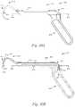
- FIG. 31Ais a perspective view of an example second tunnel member that may be used with the guide of FIGS. 29A-30B ;
- FIG. 31Bis a side elevation view of the second tunnel member of FIG. 31A ;
- FIG. 31Cis a side section view of the second tunnel member of FIG. 31B ;
- FIG. 32is a side section view of a bone with a punch inserted into the bone to form a first bone tunnel;
- FIG. 33is a side elevation view of the guide of FIGS. 29A-31C engaged with the bone of FIG. 32 and a first tunnel member inserted into the first bone tunnel;
- FIG. 34is a side elevation view of the guide of FIGS. 29A-31C engaged with the bone of FIG. 32 and the second tunnel member inserted into the bone;
- FIG. 35is a side elevation view of the guide of FIGS. 29A-31C engaged with the bone of FIG. 32 and a passer inserted into the first tunnel member;
- FIG. 36is a side elevation view of the guide of FIGS. 29A-31C engaged with the bone of FIG. 32 with a passer wire threaded through both tunnel members and protruding from the proximal end of the second tunnel member;
- FIG. 37is a side elevation view of the guide of FIGS. 29A-31C engaged with the bone of FIG. 32 with a first flexible member engaged with the passer wire and pulled through both tunnel members;
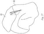
- FIG. 38is a perspective view of a bone with first and second flexible members passed through the bone.
- FIG. 39is a flowchart diagram illustrating a method of placing a flexible member transosseously through first and second transverse, intersecting bone tunnels.
- the following illustrative examplesdepict instruments and methods to form a tunnel through a bone and pass a member through the bone tunnel.
- the illustrative examplesdepict passing a round suture through a bone tunnel to attach soft tissue to the bone.
- the instruments and methods of the present disclosuremay be used to pass other elements through a bone tunnel including, suture passers, suture tapes, cables, soft tissues, grafts, and other elements. Examples of instruments and methods of the present disclosure may be used to pass any member through any bone, at surgical sites anywhere in a patient's body, and for any purpose.
- suture and suture strandare used herein to mean any strand or flexible member, natural or synthetic, able to be passed through a bone tunnel and useful in a surgical procedure.
- transverseis used herein to mean to cross at an angle; i.e. not parallel. The term includes, but is not limited to right angles.
- FIGS. 1-8depict examples of a guide and a passer for forming intersecting bone tunnels in a bone 198 and passing a flexible element through the tunnels.
- the exemplary guide 100includes a guide body 102 defining a first insertion or guide axis 104 and a second insertion or guide axis 106 intersecting at a location 108 spaced from the guide body.
- a first tunnel member 110is engageable with the guide body 102 coaxial with the first guide axis 104 and includes a proximal end 112 , a distal end 114 , and a first longitudinal passage 116 ( FIG. 7 ) at least partway through the first tunnel member 110 .
- a second tunnel member 120is engageable with the guide body 102 coaxial with the second guide axis 106 and includes a proximal end 122 , a distal end 124 , and a second longitudinal passage 126 ( FIG. 7 ) at least partway through the second tunnel member 120 .
- a passer 136( FIG. 2 ) is operable to extend from the proximal end 122 of the second tunnel member 120 , through the distal end 124 of the second tunnel member 120 , through the distal end 114 of the first tunnel member 110 , and to the proximal end 112 of the first tunnel member 110 in one continuous path.
- the passer 136may then be used to pull a flexible member or element such as, for example, a passing suture or a repair suture through the tunnel members 110 , 120 to pass the flexible element through, for example, a bone.
- the guide body 102is made up of first and second arc members 130 , 132 .
- the first and second arc members 130 , 132are joined in sliding relationship along an arc shaped path 134 of constant radius such that the guide 100 is adjustable between a first position (shown in solid lines in FIG. 1 ) in which the first guide axis and the second guide axis define a first angle between them and a second position (shown in dashed lines in FIG. 1 ) in which the first guide axis and the second guide axis define a second, larger angle between them.
- the guideis continuously adjustable over a range of included angles between the first and second guide axes 104 , 106 of from 20 to 110 degrees. More preferably, the range is 60 to 90 degrees.
- the first guide axis 104is defined by a passage in the first arc member 130 and the second guide axis 106 is defined by a passage in the second arc member 132 .
- the first tunnel membermay include a drill guide, a punch guide, a punch, or other suitable member for forming a bone tunnel and/or for inserting into a bone tunnel.
- the first tunnel member 110is a bone punch fixed to the guide body such as by pinning, threading, welding, or other suitable fixation method.
- the first tunnel member 110may be impacted into the bone 198 to form a bone tunnel in the bone.
- the first tunnel member 110includes a cylindrical body having a first, larger diameter 140 near its proximal end 112 and a second, smaller diameter 142 near its distal end with a tapered transition region 144 between the two diameters.
- the cylindrical bodydefines a first outer side wall and a first recess or side opening 146 ( FIG. 7 ) in the first side wall nearer the distal end 114 than the proximal end 112 .
- the second guide axis 106passes through the first side opening 146 for every angle in the range of adjustment of the first and second arc members 130 , 132 .
- the first longitudinal passage 116extends from the proximal end 112 of the first tunnel member 110 toward the distal end 114 and communicates with the first side opening 146 .
- a relief opening 148 in the side wallis positioned opposite the first side opening 146 and communicates with the first longitudinal passage 116 and the first side opening 146 .
- the first tunnel member 110includes indicia 150 ( FIG.
- the indicia 150include two separate marks to indicate the appropriate depth for two different sizes of anchor.
- the first tunnel member 110tapers to a solid, sharp point 152 distal to the first side opening 146 and the relief opening to facilitate driving the first tunnel member 110 into bone.
- the second tunnel membermay include a drill guide, a punch guide, a punch, or other suitable member for forming a bone tunnel and/or inserting into a bone tunnel.
- the second tunnel member 120is a punch engageable with the guide 100 in axial sliding relationship along the second guide axis 106 .
- the second tunnel member 120may be impacted into the bone 198 to form a bone tunnel in the bone.
- the second tunnel member 120includes a body having a “D”-shaped proximal portion 160 and a smaller cylindrical distal portion 162 with a tapered transition region 164 between the two portions.
- the bodydefines a second outer side wall and a second side opening 166 ( FIG. 7 ) in the first side wall nearer the distal end 124 than the proximal end 122 .
- the second longitudinal passage 126extends from the proximal end 122 of the second tunnel member 120 toward the distal end 124 of the second tunnel member 120 and communicates with the second side opening 166 .
- the second tunnel member 120tapers to a solid, sharp point 168 distal to the second side opening 166 to facilitate driving the second tunnel member 120 into bone.
- the second tunnel member 120includes an indicator to indicate when it is engaged with the first tunnel member 110 .
- the second tunnel member 120includes an index mark 170 on the outer surface readable relative to the guide 100 to indicate a depth of penetration of the second tunnel member 120 into the bone.
- the distal portion 162 of the second tunnel member 120is engageable within the first side opening 146 of the first tunnel member with the first side opening 146 and second side opening 166 in communication with one another.
- the index mark 170 on the second tunnel member 120indicates when the distal end of the second tunnel member 120 is seated in the first side opening 146 .
- the second tunnel member 120has an elongated marker such as for example a contrasting surface 171 that is exposed to indicate when the second tunnel member is not properly seated.
- the surface 171extends proximally-distally the distance of the engagement of the second tunnel member 120 with the guide body 102 .
- the surface 171is covered by the guide body 102 . If the second tunnel member 120 is not fully seated, the surface 171 is visible above the guide body. If the second tunnel member is inserted too far, for example if it deflects upon insertion such that it misses the first tunnel member and is driven past the first tunnel member, the surface 171 is visible below the guide body.
- the surface 171includes a colored stripe, for example a red colored stripe, such that if red is visible after inserting the second tunnel member it indicates that the second tunnel member is not properly seated. For example, in FIGS. 1 and 21 the surface 171 is visible above the guide body 102 and in FIGS. 5 and 22 the surface 171 is concealed by the guide body 100 .
- the relief opening 148 in the first tunnel memberallows bone chips or other debris to exit the first tunnel member 110 when the second tunnel member 120 engages it.
- an angled surface 172is formed at the distal end of the second longitudinal passage 126 facing the second side opening 166 .
- the angled surface 172deflects the passer 136 through the second side opening 166 and into the first longitudinal passage 116 when the passer is inserted.
- the “D”-shape of the proximal portion 160 of the second tunnel member 120engages the guide 100 to prevent rotation of the second tunnel member 120 as it axially translates so that the first and second side openings 146 , 166 are aligned when the first and second tunnel members 110 , 120 are engaged.
- the length of the first and second tunnel members 110 , 120 that extends from the guide body to their intersection locationmay be any desired length. However, it has been found by the inventors that for rotator cuff repair surgery on a human shoulder, a length of each member in the range of 2-8 inches is useful. More preferably the length is in the range of 4-6 inches. The length for each member may be the same or different. In the example of FIGS. 1-8 , the length of the first tunnel member extending from the guide body is approximately 5.5 inches and the length of the second tunnel member extending from the guide body is approximately 4.5 inches.
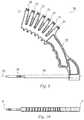
- the passer 136includes a first, or proximal, end 180 and a second, or distal, end 182 defining a loop 188 .
- the passer 136includes a relatively rigid shaft 184 extending away from the first end and a relatively flexible wire 186 attached to the shaft 184 and extending away from the shaft 184 .
- the shaft 184is a tubular member and the wire 186 is crimped, bonded, soldered, welded or otherwise attached to the shaft.
- the wire 186is formed into a loop 188 in a first plane and bent to form a curved profile 190 in a second plane perpendicular to the first plane.
- the curved profile 190 of the wire and the angled surface 172 at the distal end of the second longitudinal passage 126cooperate to facilitate advancing the distal end 182 of the passer from the second longitudinal passage 126 into the first longitudinal passage 116 .
- the passer 136includes a handle 192 at the proximal end 180 .
- the passer, or at least the wire 186is formed of a super elastic material such as nitinol, as one non-limiting example.
- the combined length of the shaft 184 and wire 186is greater than the combined length of the first and second longitudinal passages 116 , 126 such that the passer 136 is insertable through the first and second tunnel members 110 , 120 to extend through the first and second axial passages and out of the proximal end 112 of the first tunnel member 110 and out of the proximal end 122 of the second tunnel member 120 .
- the distal end 182 of the passerreaches the distal end of the second longitudinal passage 126 , it abuts the angled surface 172 and is deflected out through the second side opening 166 , through the first side opening 146 and into the first longitudinal passage 116 ( FIG. 7 ).
- the curved profile 190 of the wire and angled surface 172facilitate the transition of the wire 186 from the second tunnel member 120 to the first tunnel member 110 and promote passage even when the first and second tunnel members 110 , 120 are engaged at an acute angle.
- the passeris further advanced to move the distal end 182 of the passer through the second longitudinal passage and out the proximal end 112 of the first tunnel member 110 ( FIG. 5 ).
- a member 191e.g.
- a suturemay be placed in the loop 188 at the distal end 182 of the passer and the passer 136 may be retrieved to pull the member 191 through the first longitudinal passage 116 , through the first side opening 146 , through the second side opening 166 , through the second longitudinal passage 126 and out the proximal end of the second longitudinal passage 126 .
- the passer handleincludes an indicator, for example a flat surface 197 , to indicate to a user the orientation of the bent loop 188 so that the user can orient it to engage the angled surface 172 .
- the passermay be keyed to the second tunnel member to permit only one orientation.
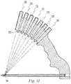
- FIGS. 9-11illustrate another example of a guide instrument 300 similar to that of FIG. 1 but showing a different arrangement of the second guide axis.
- the guide body 302includes a first tunnel member 304 like the first tunnel member in the example of FIG. 1 that defines a first guide axis 306 as with the example of FIG. 1 .
- the guide bodyis a unitary body having a plurality of receivers 308 , 310 , 312 , 314 , 316 , 318 , 320 operable to receive the second tunnel member 120 .
- Each receiverincludes a passage defining a guide axis. Any number of receivers may be included at any desired spacing to provide a desired selection of guide angles relative to the first guide axis. In the example of FIGS.
- each of the second through eighth guide axesintersects the first guide axis 304 at the same location spaced from the guide body and each can selectively receive the second tunnel member.
- each of the second through eighth guide axesintersects a side opening 346 in the first tunnel member like the side opening 146 in the example of FIG. 1 .
- a surface 333 formed at the distal end of each receiverengages the flat side of the “D”-shaped second tunnel member 120 to prevent rotation of the second tunnel member 120 within the receiver so that the first and second side openings 146 , 346 are properly aligned when the first and second tunnel members are engaged.
- the second through eighth guide axesare equally spaced and define angles of 45 degrees to 75 degrees relative to the first guide axis 306 .
- Indicia 350 on the first tunnel member 304indicates an insertion depth range suitable for a fastener, for example a knotless fastener.
- Indicia 351 on each receiverindicates the angle corresponding to each receiver.
- the spacingcan be any desired spacing and can be uniform or non-uniform to provide a range of angles useful to the user. The inventors have found the spacing and range shown in the example to be suitable for typical rotator cuff procedures of the human shoulder.
- first and second tunnel membermay be varied.
- a guide having an angular range of 50 to 80 degreeshas been found suitable with either a sliding adjustable guide like that of FIG. 1 or a unibody guide like that of FIG. 9 .
- a unibody guidefour receivers defining axes at 50, 60, 70 and 80 degrees relative to the first guide axis have been found to be suitable.
- Any length of first and second tunnel membersmay be used.
- first and second tunnel memberseach extending from the guide body a distance in the range of two to three inches has been found suitable.
- FIGS. 12-13illustrate another arrangement for a passer 400 similar to that of FIG. 2 .
- the passer 400includes an outer tube 402 engaged coaxially with the shaft 484 in axial sliding relationship and moveable relative to the shaft from a first position in which the outer tube encloses a portion of the wire length ( FIG. 13 ) and a second position in which the outer tube encloses less of the wire length ( FIG. 12 ).
- the outer tubeis relatively rigid relative to the wire 486 .
- the outer tubeaids in inserting the passer 400 into the second tunnel member by holding the wire 486 in a straight and rigid configuration when the tube is in the first position.
- the outer tubemay enclose any portion of the wire length in the first position to aid in inserting the passer.
- the outer tubein the first position, encloses more than one-half of the wire length; more preferably 60 to 100 percent of the wire length; more preferably 80 to 100 percent of the wire length; more preferably the entire wire length including all of the loop 488 .
- the outer tubein the second position, enough of the wire is exposed to allow it to extend through the side openings in the first and second tunnel members and through the first tunnel member.
- the outer tubeencloses less than one-half of the wire length; more preferably less than 20 percent of the wire length. The tube may be inserted into the second tunnel member while in the first position and then shaft 484 advanced to extend the wire 486 out of the outer tube 402 and through the second and first tunnel members.
- a handle 492 on the shaftmay be pressed toward a handle 493 on the outer tube to advance the wire.
- the loop 488 in the example of FIGS. 12 and 13includes a first bend 487 angled away from the main portion of the wire 486 and a second bend 489 at the distal end forming a small radius. The bends 487 , 489 facilitate the transition of the loop through the side openings of the tunnel members.
- the exemplary guides and methods of the present disclosuremake it possible to form intersecting bone tunnels in a bone and extend, in one motion, a passer through the guide and bone tunnels from a first position external to the bone to a second position external to the bone.
- a first end of a membersuch as a suture, may then be engaged with the passer outside of the bone tunnels.
- the first end of the membermay then be passed, in one motion, through the guide and bone tunnels from the second position external to the bone to a first position external to the bone to thread the member through the intersecting bone tunnels.
- the membermay be used in any desirable manner.
- a member in the form of a suture 194may be so passed and then used to secure soft tissue 196 to the bone 198 as shown in FIGS. 14 and 15 .
- a guide according to examples of the present disclosuremay be used to create three or more intersecting tunnels and pass flexible elements through the tunnels.
- the second tunnel member 120may be withdrawn from the bone.
- the guide 100may be rotated about the first guide axis 104 , as shown at reference numeral 193 , and/or the angle between the guide axes 104 may be adjusted as shown at reference numeral 195 in FIG. 17 .
- a unitary guidesuch as the example of FIG.
- the angle between the guide axesmay be adjusted by inserting the second tunnel member in a different receiver.
- the second tunnel member 120may then be inserted into the bone 198 in a new location and advanced to form a third bone tunnel intersecting the first bone tunnel.
- the second tunnel member 120may be engaged with the first tunnel member 110 and the passer 136 used to pass a second flexible element through the first and third tunnels. This may be repeated as many times as desired to provide a one-to-many relationship between the first bone tunnel and the plurality of additional bone tunnels intersecting the first bone tunnel.
- the third and subsequent bone tunnelsmay be formed and the second and subsequent flexible elements may be passed while the first tunnel member 110 remains in the bone and while the first flexible element remains in the first tunnel member.
- FIGS. 18-27illustrate an example of a surgical method according to the present disclosure.
- instruments and methods of the previous examplesare shown in use to place transosseous sutures to repair a rotator cuff 202 of a shoulder joint.
- any of the examples of instruments and methods of the present disclosuremay be used in any combination to pass a member through a shoulder bone or other bones at a shoulder or other surgical sites and for rotator cuff repair or other surgical purposes.
- the guide 100is positioned with the point 152 of the first tunnel member 110 on the lateral surface of the greater tuberosity 200 of the humerus approximately 30 mm inferior to the superior border of the tuberosity.
- the guide 100is oriented such that it is perpendicular to the long axis of the humerus and perpendicular to the acromion (not shown).
- the first tunnel member 110is impacted into the bone to form a first, or lateral, bone tunnel 210 .
- the location for a second, or medial, tunnelis visualized using a targeting wire 204 in a targeting sleeve 206 to constrain the wire 204 to translation along the second guide axis 106 .
- the position of the targeting wiremay be adjusted in two degrees of freedom.
- the guide 100may be rotated about the first guide axis 104 by twisting the first tunnel member 110 in the lateral bone tunnel 210 .
- the guidemay be repositioned by adjusting the first and second arc members 130 , 132 to change the angle between the guide axes 104 , 106 (or repositioning the targeting sleeve and targeting wire in a different receiver in a unitary guide such as that of FIG. 9 ).
- the targeting wire 204may be inserted through the skin and other soft tissues near the targeted site so that the position may be visualized on the bone.
- the small punctures in the skin and other soft tissues created by the targeting wire 204cause minimal trauma to the tissues and facilitate multiple targeting attempts if needed.
- the targeting wire 204is then used to mark the bone surface with the desired medial tunnel location.
- the targeting sleeve and wireare removed and the second tunnel member 120 is impacted to form a second, or medial, tunnel 212 .
- the second tunnel member 120is engaged with the first tunnel member 110 and the passer 400 inserted into the second tunnel member 120 .
- the wireis advanced through the first and second tunnel members 110 , 120 until it extends from the proximal end of the first tunnel member 110 .
- the end 216 of a first shuttle suture 214is passed through the loop 488 of the passer 400 .
- the end 216 of the shuttle suture 214is retrieved by pulling the passer 136 out the distal end of the second tunnel member 120 .
- the second tunnel member 120is removed leaving the first shuttle suture 214 in place in the first tunnel member 110 and extending out of the second, medial bone tunnel 212 .
- the preceding stepsare repeated to create a third, additional medial, tunnel 218 and place a second shuttle suture 219 while the first tunnel member 110 remains in the bone and while the first shuttle suture 214 remains in the first tunnel member 110 .
- Two limbs 220 , 222 of a first repair sutureare passed through the loop of the first shuttle suture 214 and two limbs 224 , 226 of a second repair suture are passed through the loop of the second shuttle suture 219 .
- the shuttle sutures 214 , 219are pulled to pass the limbs of the repair sutures through the bone.
- the repair suturesare passed through the rotator cuff 202 and used to secure it to the humerus 200 .
- the instruments and methodsmay also be used for other repairs such as, for example, an Achilles tendon repair in which the first and second tunnel members are inserted into the heel bone 500 and one or more sutures are passed and used to secure the Achilles tendon 502 to the bone 500 .
- an Achilles tendon repairin which the first and second tunnel members are inserted into the heel bone 500 and one or more sutures are passed and used to secure the Achilles tendon 502 to the bone 500 .
- bone tunnelsbeing formed by punching instruments into the bone
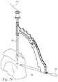
- FIGS. 29A-31Cdepict another example surgical instrument or guide 600 that may be used place a flexible member transosseously through first and second bone tunnels oriented transverse to each other and intersecting one other at a location within a bone.
- FIGS. 32-39depict methods for placing a flexible member transosseously through first and second transverse, intersecting bone tunnels utilizing the guide 600 shown in FIGS. 29A-31C .
- the guide 600may include a guide body 602 .
- the guide body 602may include a first tunnel member 610 , a longitudinal guide body passage 632 ( FIG. 30B ), a guide body handle portion 630 , and a detent mechanism 640 .
- the first tunnel member 610may be engaged with the guide body 602 in a fixed fashion, or in a removably engaged fashion, and may include a proximal end 612 , a distal end 614 , a distal opening 646 , a curved portion 634 that is nearer the distal end 614 than the proximal end 612 of the first tunnel member 610 , and a first longitudinal passage 616 ( FIG. 30B ) that extends through the first tunnel member 610 and communicates with the distal opening 646 .
- the curved portion 634may include a first bend 631 , a second bend 633 , a third bend 635 , a first straight segment 636 and a second straight segment 637 .
- the curved portion 634may include a single continuous bend, or any number of bends and/or any number of straight segments, without departing from the spirit or scope of the present disclosure.
- the distal end 614 of the first tunnel member 610may define a first guide axis 604 and at least a portion of the first longitudinal passage 616 , near the distal end 614 of the first tunnel member 610 , may be coaxial with the first guide axis 604 .
- the longitudinal guide body passage 632may be formed in the guide body 602 and may define a second guide axis 606 .
- the first guide axis 604 and the second guide axismay be configured to intersect each other at a location spaced from the guide body 602 and at least a portion of the first longitudinal passage 616 near the proximal end 612 of the first tunnel member 610 may be parallel with the second guide axis 606 and/or parallel with the longitudinal guide body passage 632 .
- the detent mechanism 640may be formed in the guide body handle portion 630 and may include a spring-biased ball plunger 642 that protrudes into the longitudinal guide body passage 632 , as will be explained in more detail below.
- the guide 600may include a second tunnel member 620 .
- the second tunnel member 620may be a bone punch that is removably engaged with the longitudinal guide body passage 632 .
- the second tunnel member 620may be separable from the guide body 602 and may engage the guide body 602 in an axial sliding relationship along the second guide axis 606 within the longitudinal guide body passage 632 .
- the second tunnel member 620may include a proximal end 622 , a distal end 624 , a second longitudinal passage 626 , a side wall 667 , a side opening 666 , a sharp point 668 , an annular notch 644 , a handle 650 , a first aperture 652 formed in the handle 650 , and a second aperture 654 formed in the handle 650 .
- the second longitudinal passage 626may extend at least partway through the second tunnel member 620 and the second longitudinal passage 626 may be coaxial with the second guide axis 606 when the second tunnel member 620 is engaged within the longitudinal guide body passage 632 .
- the detent mechanism 640may be configured to engage and retain the second tunnel member 620 in a desired axial position relative to the guide body 602 , causing the second tunnel member 620 to resist axial movement along the second guide axis 606 .
- the annular notch 644 that is formed in the side wall 667 of the second tunnel member 620may have a complementary shape that interacts with the spring-biased ball plunger 642 of the detent mechanism 640 to resist axial sliding of the second tunnel member 620 within the longitudinal guide body passage 632 . This feature may help prevent the second tunnel member 620 from accidentally falling out of the longitudinal guide body passage 632 as the guide 600 is moved about during surgical procedures.
- the spring-biased ball plunger 642may achieve this function by engaging within the annular notch 644 and resisting axial sliding of the second tunnel member 620 due to a spring-biased forced that is placed upon the ball plunger. However, the surgeon can still freely rotate the second tunnel member 620 within the longitudinal guide body passage 632 because the spring-biased ball plunger 642 will remain within the annular notch 644 as the second tunnel member 620 is rotated within the longitudinal guide body passage 632 .
- sufficient axial forcemay be applied to the second tunnel member 620 to overcome the force of the spring-biased ball plunger 642 and eject the spring-biased ball plunger 642 from within the annular notch 644 and freely slide the second tunnel member 620 axially within longitudinal guide body passage 632 .
- the side opening 666may be formed in the side wall 667 nearer the distal end 624 of the second tunnel member 620 than the proximal end 622 of the second tunnel member 620 .
- the second longitudinal passage 626may extend from the proximal end 622 of the second tunnel member 620 toward the distal end 624 of the second tunnel member 620 and may communicate with the side opening 666 .
- the side opening 666 formed in the second tunnel member 620 , and the distal opening 646 of the first tunnel member 610may be in communication with each other when the second tunnel member 620 is axially translated such that the first guide axis 604 intersects the side opening 666 of the second tunnel member 620 .
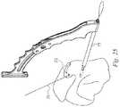
- FIGS. 35-37show how the guide 600 may be used with a passer, such as the passer 400 shown in FIGS. 12-13 .
- the passer 400may be operable to extend from the proximal end 612 of the first tunnel member 610 , through the distal end 614 of the first tunnel member 610 , through the distal end 624 of the second tunnel member 620 , and to the proximal end 622 of the second tunnel member 620 in one continuous path.
- the passer 400may then be used to pull a flexible member 714 such as, for example, a passing suture or a repair suture through the tunnel members 610 , 620 to pass the flexible member 714 through the bone 698 .
- FIGS. 32-38illustrate an example of a surgical method according to the present disclosure.
- instruments and methods of the previous examplesare shown in use to place transosseous sutures to repair a rotator cuff of a shoulder joint.
- any of the examples of instruments and methods of the present disclosuremay be used in any combination to pass a member through a shoulder bone or other bones at a shoulder or other surgical sites and for rotator cuff repair and/or other surgical purposes.
- a tool 800such as a medial bone punch, a bone drill, etc., may be used to form a first bone tunnel in the bone 698 .
- the guide 600may be placed proximal the bone 698 with the distal end 614 of the first tunnel member 610 inserted into the first bone tunnel that was formed by the tool 800 in FIG. 33 .
- the guide 600may be rotated back and forth, and pitched up and down, while the first tunnel member 610 is inserted into the first bone tunnel to position the sharp point 668 of the second tunnel member 620 at the desired location on the surface of the bone 698 before punching the second bone tunnel into the bone 698 using the second tunnel member 620 .
- the desired location of the sharp point 668 of the first tunnel member 110 on the surface of the bone 698may be on the lateral surface of the greater tuberosity 699 of the humerus approximately 30 mm inferior to the superior border of the tuberosity.
- the guide 600may be oriented such that it is perpendicular to the long axis of the humerus and perpendicular to the acromion (not shown).
- the second tunnel member 620may be impacted into the bone 698 to form the second bone tunnel.
- the second tunnel member 620may also be rotated/oriented to engage the distal opening 646 of the first tunnel member 610 with the side opening 666 of the second tunnel member 620 , such that the distal opening 646 of the first tunnel member 610 and the side opening 666 of the second tunnel member 620 are in communication with each other.
- the passer 400may be inserted into the proximal end 612 of the first tunnel member 610 .
- the wire 486 of the passer 400may be advanced through the first tunnel member 610 , into the second tunnel member 620 , and then further advanced until the bent loop 488 on the end of the wire 486 protrudes from the proximal end 622 of the second tunnel member 620 .
- the first flexible member 714may be passed through the bent loop 488 of the wire 486 , to engage the first flexible member 714 with the passer 400 , and the first flexible member 714 may then be threaded through the tunnel members 610 , 620 (and the bone tunnels) by pulling the wire 486 out of the proximal end 612 of the first tunnel member 610 .
- first tunnel member 610 and the second tunnel member 620are removed from the bone tunnels, along with the guide 600 , leaving the first flexible member 714 in place in the bone 698 . Moreover, the preceding steps may be repeated to create additional bone tunnels and place a second flexible member 719 (or more flexible members, as desired), as shown in FIG. 38 .
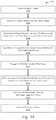
- FIG. 39a flowchart diagram is shown of a method 1000 of placing a flexible member transosseously through first and second transverse, intersecting bone tunnels, according to embodiments of the present disclosure.
- the method 1000may be carried out through the use of any of the surgical instruments of FIGS. 1-37 .
- the method 1000may be carried out with surgical instruments different from those shown in FIGS. 1-37 and/or described elsewhere herein.
- the method 1000may begin with a step 1002 , in which a first bone tunnel may be formed in a bone 698 .
- the first bone tunnelmay be sized and configured to receive a first tunnel member 610 therein.
- the method 1000may then proceed to a step 1004 , in which a first tunnel member 610 may be inserted into the first bone tunnel of the bone 698 along a first insertion axis 604 .
- the first tunnel member 610may include a proximal end 612 , a distal end 614 , and a first longitudinal passage 616 extending through the first tunnel member 610 .
- the method 1000may then proceed to a step 1006 , in which a second tunnel member 620 may be inserted into the bone 698 along a second insertion axis 606 and the second insertion axis 606 may intersect the first insertion axis 604 .
- the second tunnel member 620may be punched into the bone 698 to form a second bone tunnel and insert the second tunnel member 620 into the bone 698 along the second insertion axis 606 after the first tunnel member 610 has been inserted into the first bone tunnel.
- the second tunnel member 620may include a proximal end 622 , a distal end 624 , and a second longitudinal passage 626 extending at least partway through the second tunnel member 620 .
- the method 1000may then proceed to a step 1008 , in which a passer 400 may be inserted through the first and second tunnel members 610 , 620 in one continuous motion until the passer 400 extends through the first longitudinal passage 616 , the second longitudinal passage 626 , out of the proximal end 612 of the first tunnel member 610 , and out of the proximal end 622 of the second tunnel member 620 .
- the passer 400may be inserted through the first and second tunnel members 610 , 620 by inserting the passer 400 so that it extends between the proximal end 612 of the first longitudinal passage 616 , the distal end 614 of the first longitudinal passage 616 , the distal end 624 of the second longitudinal passage 626 , and the proximal end 622 of the second longitudinal passage 626 by advancing the passer 400 into the proximal end 612 of the first tunnel member 610 , along the first longitudinal passage 616 , through a distal opening 646 in the first tunnel member 610 , through a side opening 666 in the second tunnel member 620 , along the second longitudinal passage 626 , and out a proximal end 622 of the second tunnel member 620 in one continuous motion.
- the passer 400may also include a wire 486 forming a loop 488 in a first plane, the loop 488 being bent so that a portion of the loop 488 forms a curved profile in a second plane perpendicular to the first plane and an outer tube 402 that is moveable relative to the wire 486 between a first position in which the outer tube 402 encloses a portion of a length of the wire 486 and a second position in which the outer tube 402 encloses less of the length of the wire 486 .
- the wire 486may be inserted into the first tunnel member 610 while the outer tube 402 is positioned in the first position and the outer tube 402 may be subsequently moved to the second position to pass the loop 488 from the distal opening 646 in the first tunnel member 610 through the side opening 666 in the second tunnel member 620 and out the proximal end 622 of the second tunnel member 620 .
- the method 1000may then proceed to a step 1010 , in which a first flexible member 714 may be engaged with the loop 488 of the passer 400 .
- the method 1000may then proceed to a step 1012 , in which the passer 400 may be withdrawn from the proximal end 612 of the first tunnel member 610 to pass the first flexible member 714 through the first and second tunnel members 610 , 620 and the first and second bone tunnels.
- the method 1000may then proceed to a step 1014 , in which the first flexible member 714 may be passed through soft tissue (not shown) adjacent to the bone 698 .
- the method 1000may then proceed to a step 1016 , in which the first flexible member 714 may then be used to secure the soft tissue to the bone 698 .
- the method 1000may proceed to a step 1018 , in which the soft tissue may be secured to the bone 698 by inserting a knotless anchor (not shown) into the first bone tunnel and securing the first flexible member 714 with the knotless anchor, and the method 1000 may end.
- a knotless anchornot shown
- phrases “connected to,” “coupled to” and “in communication with”refer to any form of interaction between two or more entities, including mechanical, electrical, magnetic, electromagnetic, fluid, and thermal interaction. Two components may be functionally coupled to each other even though they are not in direct contact with each other.
- the term “abutting”refers to items that are in direct physical contact with each other, although the items may not necessarily be attached together.
- the phrase “fluid communication”refers to two features that are connected such that a fluid within one feature is able to pass into the other feature.
Landscapes
- Health & Medical Sciences (AREA)
- Surgery (AREA)
- Life Sciences & Earth Sciences (AREA)
- Orthopedic Medicine & Surgery (AREA)
- Molecular Biology (AREA)
- Medical Informatics (AREA)
- Veterinary Medicine (AREA)
- Public Health (AREA)
- Engineering & Computer Science (AREA)
- Biomedical Technology (AREA)
- Heart & Thoracic Surgery (AREA)
- Nuclear Medicine, Radiotherapy & Molecular Imaging (AREA)
- General Health & Medical Sciences (AREA)
- Animal Behavior & Ethology (AREA)
- Dentistry (AREA)
- Oral & Maxillofacial Surgery (AREA)
- Rheumatology (AREA)
- Surgical Instruments (AREA)
Abstract
Description
Claims (20)
Priority Applications (3)
| Application Number | Priority Date | Filing Date | Title |
|---|---|---|---|
| US15/887,095US10820918B2 (en) | 2015-07-17 | 2018-02-02 | Transosseous guide and method |
| US17/068,909US11504140B2 (en) | 2015-07-17 | 2020-10-13 | Transosseous guide and method |
| US18/057,108US20230083535A1 (en) | 2015-07-17 | 2022-11-18 | Transosseous Guide And Method |
Applications Claiming Priority (4)
| Application Number | Priority Date | Filing Date | Title |
|---|---|---|---|
| US201562193888P | 2015-07-17 | 2015-07-17 | |
| US15/211,673US10154868B2 (en) | 2015-07-17 | 2016-07-15 | Transosseous method |
| US15/211,764US10258401B2 (en) | 2015-07-17 | 2016-07-15 | Transosseous guide |
| US15/887,095US10820918B2 (en) | 2015-07-17 | 2018-02-02 | Transosseous guide and method |
Related Parent Applications (2)
| Application Number | Title | Priority Date | Filing Date |
|---|---|---|---|
| US15/211,673Continuation-In-PartUS10154868B2 (en) | 2015-07-17 | 2016-07-15 | Transosseous method |
| US15/211,764Continuation-In-PartUS10258401B2 (en) | 2015-07-17 | 2016-07-15 | Transosseous guide |
Related Child Applications (1)
| Application Number | Title | Priority Date | Filing Date |
|---|---|---|---|
| US17/068,909DivisionUS11504140B2 (en) | 2015-07-17 | 2020-10-13 | Transosseous guide and method |
Publications (2)
| Publication Number | Publication Date |
|---|---|
| US20180153566A1 US20180153566A1 (en) | 2018-06-07 |
| US10820918B2true US10820918B2 (en) | 2020-11-03 |
Family
ID=62240621
Family Applications (3)
| Application Number | Title | Priority Date | Filing Date |
|---|---|---|---|
| US15/887,095Active2036-12-04US10820918B2 (en) | 2015-07-17 | 2018-02-02 | Transosseous guide and method |
| US17/068,909Active2036-07-16US11504140B2 (en) | 2015-07-17 | 2020-10-13 | Transosseous guide and method |
| US18/057,108AbandonedUS20230083535A1 (en) | 2015-07-17 | 2022-11-18 | Transosseous Guide And Method |
Family Applications After (2)
| Application Number | Title | Priority Date | Filing Date |
|---|---|---|---|
| US17/068,909Active2036-07-16US11504140B2 (en) | 2015-07-17 | 2020-10-13 | Transosseous guide and method |
| US18/057,108AbandonedUS20230083535A1 (en) | 2015-07-17 | 2022-11-18 | Transosseous Guide And Method |
Country Status (1)
| Country | Link |
|---|---|
| US (3) | US10820918B2 (en) |
Families Citing this family (8)
| Publication number | Priority date | Publication date | Assignee | Title |
|---|---|---|---|---|
| SE543049C2 (en)* | 2019-03-28 | 2020-09-29 | Meouchy Wissam El | Instruments for attaching soft tissue to bone |
| US11357517B1 (en) | 2019-04-25 | 2022-06-14 | Nirav H. Amin | System and method for creating graft tunnels in bone |
| IT202000001024A1 (en)* | 2020-01-21 | 2021-07-21 | Ncs Lab S R L | Surgical instrument for orthopedics |
| CZ2020537A3 (en)* | 2020-09-30 | 2022-03-09 | Sportbalance s.r.o. | Rotator cuff suture target and method of its use |
| CN112869797A (en)* | 2021-03-16 | 2021-06-01 | 上海竞微扶生医学科技有限公司 | Conveyor, wire passing device, tunnel type wire passing system and operation method thereof |
| WO2023010151A1 (en)* | 2021-08-04 | 2023-02-09 | Georgius Peter | Arch bar wire applicator |
| US20250017719A1 (en) | 2023-07-12 | 2025-01-16 | Integrity Medical Services Inc. | Tissue repair devices, systems, and methods |
| US12433583B1 (en) | 2024-05-31 | 2025-10-07 | Integrity Medical Services Inc. | Suture passer devices, systems, and methods |
Citations (8)
| Publication number | Priority date | Publication date | Assignee | Title |
|---|---|---|---|---|
| US20070005067A1 (en)* | 2005-06-21 | 2007-01-04 | Brian Dross | Arthoscopic method and apparatus for tissue attachment to bone |
| US20100106194A1 (en)* | 2004-10-26 | 2010-04-29 | P Tech, Llc | Stabilizing a spinal anatomical structure |
| US20110009867A1 (en)* | 2008-02-28 | 2011-01-13 | T.A.G. Medical Products Corporation Ltd. | Medical apparatus and method for attaching a suture to a bone |
| US20110295279A1 (en)* | 2010-05-25 | 2011-12-01 | Biomet Sports Medicine, Llc | Method and Apparatus for Passing a Suture |
| US20130123840A1 (en)* | 2011-11-11 | 2013-05-16 | VentureMD Innovations, LLC | Transosseous attachment |
| US20160015380A1 (en)* | 2013-03-18 | 2016-01-21 | Mininvasive Ltd. | Arthroscopic surgical device |
| US20170014172A1 (en)* | 2015-07-17 | 2017-01-19 | Kator, Llc | Transosseous guide |
| US20180078251A1 (en)* | 2015-03-27 | 2018-03-22 | Paragon Surgical Llc | Suture delivery device |
Family Cites Families (450)
| Publication number | Priority date | Publication date | Assignee | Title |
|---|---|---|---|---|
| US1586721A (en) | 1923-08-28 | 1926-06-01 | William A Tryon | Shackle |
| US1583271A (en) | 1925-01-14 | 1926-05-04 | Biro Ladislaus | Surgical instrument |
| US1856721A (en) | 1931-02-07 | 1932-05-03 | Clemens B Nagelmann | Suturing and ligating instrument |
| US2291413A (en) | 1941-06-13 | 1942-07-28 | John R Siebrandt | Bone clamping and wire adjusting means |
| US4312337A (en) | 1980-09-08 | 1982-01-26 | Donohue Brian T | Cannula and drill guide apparatus |
| US4741330A (en) | 1983-05-19 | 1988-05-03 | Hayhurst John O | Method and apparatus for anchoring and manipulating cartilage |
| US5417691A (en) | 1982-05-20 | 1995-05-23 | Hayhurst; John O. | Apparatus and method for manipulating and anchoring tissue |
| US5601557A (en) | 1982-05-20 | 1997-02-11 | Hayhurst; John O. | Anchoring and manipulating tissue |
| US6656182B1 (en) | 1982-05-20 | 2003-12-02 | John O. Hayhurst | Tissue manipulation |
| US4441497A (en) | 1982-10-21 | 1984-04-10 | Paudler Franklin T | Universal suture passer |
| US4672957A (en) | 1983-10-04 | 1987-06-16 | South African Inventions Development Corporation | Surgical device |
| US4622960A (en) | 1985-06-07 | 1986-11-18 | Tam John W | Instrument for wire manipulation in bone surgery |
| US4738255A (en) | 1986-04-07 | 1988-04-19 | Biotron Labs, Inc. | Suture anchor system |
| US4898156A (en) | 1987-05-18 | 1990-02-06 | Mitek Surgical Products, Inc. | Suture anchor |
| US4809408A (en) | 1987-09-21 | 1989-03-07 | Abrahamson Thomas C | Shielded wedge-type cable clamp |
| US4890615B1 (en) | 1987-11-05 | 1993-11-16 | Linvatec Corporation | Arthroscopic suturing instrument |
| US4959069A (en) | 1989-10-20 | 1990-09-25 | Ethicon, Inc. | Braided surgical sutures |
| US5037422A (en) | 1990-07-02 | 1991-08-06 | Acufex Microsurgical, Inc. | Bone anchor and method of anchoring a suture to a bone |
| US5236445A (en) | 1990-07-02 | 1993-08-17 | American Cyanamid Company | Expandable bone anchor and method of anchoring a suture to a bone |
| US5041129A (en) | 1990-07-02 | 1991-08-20 | Acufex Microsurgical, Inc. | Slotted suture anchor and method of anchoring a suture |
| US5269809A (en) | 1990-07-02 | 1993-12-14 | American Cyanamid Company | Locking mechanism for use with a slotted suture anchor |
| US5224946A (en) | 1990-07-02 | 1993-07-06 | American Cyanamid Company | Bone anchor and method of anchoring a suture to a bone |
| US5100417A (en) | 1990-07-13 | 1992-03-31 | American Cyanamid Company | Suture anchor and driver assembly |
| US5258016A (en) | 1990-07-13 | 1993-11-02 | American Cyanamid Company | Suture anchor and driver assembly |
| US5725529A (en) | 1990-09-25 | 1998-03-10 | Innovasive Devices, Inc. | Bone fastener |
| US5860978A (en) | 1990-09-25 | 1999-01-19 | Innovasive Devices, Inc. | Methods and apparatus for preventing migration of sutures through transosseous tunnels |
| ATE174777T1 (en) | 1990-09-25 | 1999-01-15 | Innovasive Devices Inc | BONE FIXATION DEVICE |
| US7074203B1 (en) | 1990-09-25 | 2006-07-11 | Depuy Mitek, Inc. | Bone anchor and deployment device therefor |
| US5257996A (en) | 1991-12-13 | 1993-11-02 | Mcguire David A | Surgical pin passer |
| DE4106823C1 (en) | 1991-03-04 | 1992-06-25 | Liebscher Kunststofftechnik, 8032 Graefelfing, De | |
| US5480403A (en) | 1991-03-22 | 1996-01-02 | United States Surgical Corporation | Suture anchoring device and method |
| GB2260704B (en) | 1991-09-30 | 1995-08-23 | Philip Richardson | Suturing apparatus |
| US5766221A (en) | 1991-12-03 | 1998-06-16 | Boston Scientific Technology, Inc. | Bone anchor implantation device |
| US5439467A (en) | 1991-12-03 | 1995-08-08 | Vesica Medical, Inc. | Suture passer |
| CA2181674A1 (en) | 1991-12-03 | 1993-10-04 | Theodore V. Benderev | Support structure for supporting and positioning medical equipment |
| US6001104A (en) | 1991-12-03 | 1999-12-14 | Boston Scientific Technology, Inc. | Bone anchor implantation device |
| US5176682A (en) | 1992-06-01 | 1993-01-05 | Chow James C Y | Surgical implement |
| US5637112A (en) | 1992-06-08 | 1997-06-10 | Orthopedic Systems, Inc. | Apparatus for attaching suture to bone |
| US5250055A (en) | 1992-06-08 | 1993-10-05 | Orthopedic Systems Inc. | Method and apparatus for tying suture to bone |
| US5254126A (en) | 1992-06-24 | 1993-10-19 | Ethicon, Inc. | Endoscopic suture punch |
| US5342369A (en) | 1992-09-11 | 1994-08-30 | The Board Of Regents Of The University Of Washington | System for repair of bankart lesions |
| US5624446A (en) | 1992-09-11 | 1997-04-29 | University Of Washington | System for repair of capsulo-labral separations |
| US5354300A (en) | 1993-01-15 | 1994-10-11 | Depuy Inc. | Drill guide apparatus for installing a transverse pin |
| US5350380A (en) | 1993-01-15 | 1994-09-27 | Depuy Inc. | Method for securing a ligament replacement in a bone |
| US5814073A (en) | 1996-12-13 | 1998-09-29 | Bonutti; Peter M. | Method and apparatus for positioning a suture anchor |
| US5417701A (en) | 1993-03-30 | 1995-05-23 | Holmed Corporation | Surgical instrument with magnetic needle holder |
| US5312438A (en) | 1993-05-03 | 1994-05-17 | Lanny L. Johnson | Suture anchor and method of use |
| US5562687A (en) | 1993-07-12 | 1996-10-08 | Mitek Surgical Products, Inc. | Surgical repair kit and its method of use |
| US6629984B1 (en) | 1998-07-07 | 2003-10-07 | Kwan-Ho Chan | Surgical repair kit and its method of use |
| US5330468A (en) | 1993-10-12 | 1994-07-19 | Burkhart Stephen S | Drill guide device for arthroscopic surgery |
| US5545180A (en) | 1993-12-13 | 1996-08-13 | Ethicon, Inc. | Umbrella-shaped suture anchor device with actuating ring member |
| US5690677A (en) | 1994-02-17 | 1997-11-25 | Arthrex, Inc. | Method for installing a suture anchor through a cannulated tissue-shifting guide |
| US5466243A (en) | 1994-02-17 | 1995-11-14 | Arthrex, Inc. | Method and apparatus for installing a suture anchor through a hollow cannulated grasper |
| US5486197A (en) | 1994-03-24 | 1996-01-23 | Ethicon, Inc. | Two-piece suture anchor with barbs |
| US5584836A (en) | 1994-04-07 | 1996-12-17 | Smith & Nephew Richards, Inc. | Cannulated medical suture anchor |
| US5411523A (en) | 1994-04-11 | 1995-05-02 | Mitek Surgical Products, Inc. | Suture anchor and driver combination |
| US5683418A (en) | 1994-04-29 | 1997-11-04 | Mitek Surgical Products, Inc. | Wedge shaped suture anchor and method of implantation |
| US5630824A (en) | 1994-06-01 | 1997-05-20 | Innovasive Devices, Inc. | Suture attachment device |
| US5843127A (en) | 1994-08-22 | 1998-12-01 | Le Medical Technologies, Inc. | Fixation device and method for installing same |
| US5464427A (en) | 1994-10-04 | 1995-11-07 | Synthes (U.S.A.) | Expanding suture anchor |
| US5562684A (en) | 1994-10-11 | 1996-10-08 | Ethicon, Inc. | Surgical knot pusher device and improved method of forming knots |
| US5649963A (en) | 1994-11-10 | 1997-07-22 | Innovasive Devices, Inc. | Suture anchor assembly and methods |
| US5643321A (en) | 1994-11-10 | 1997-07-01 | Innovasive Devices | Suture anchor assembly and methods |
| US5814071A (en) | 1994-11-10 | 1998-09-29 | Innovasive Devices, Inc. | Suture anchor assembly and methods |
| US5584839A (en) | 1994-12-12 | 1996-12-17 | Gieringer; Robert E. | Intraarticular drill guide and arthroscopic methods |
| US5601562A (en) | 1995-02-14 | 1997-02-11 | Arthrex, Inc. | Forked insertion tool and metnod of arthroscopic surgery using the same |
| US5569306A (en) | 1995-06-06 | 1996-10-29 | Thal; Raymond | Knotless suture anchor assembly |
| EP0910287B1 (en) | 1995-06-06 | 2007-12-19 | Raymond Thal | Knotless suture anchor assembly |
| US6086608A (en) | 1996-02-22 | 2000-07-11 | Smith & Nephew, Inc. | Suture collet |
| US5730747A (en) | 1995-06-07 | 1998-03-24 | Smith & Nephew, Inc. | Suture passing forceps |
| US5572770A (en) | 1995-08-18 | 1996-11-12 | Boden; Robert O. | Self locking cord lock |
| US5681333A (en) | 1995-11-08 | 1997-10-28 | Arthrex, Inc. | Method and apparatus for arthroscopic rotator cuff repair utilizing bone tunnels for suture attachment |
| US5645568A (en) | 1995-11-20 | 1997-07-08 | Medicinelodge, Inc. | Expandable body suture |
| US5824009A (en) | 1995-12-06 | 1998-10-20 | Kabushiki Kaisha Matsutani Seisakusho | Guide instrument for a medical needle with thread |
| US5702397A (en) | 1996-02-20 | 1997-12-30 | Medicinelodge, Inc. | Ligament bone anchor and method for its use |
| US5755728A (en) | 1996-03-07 | 1998-05-26 | Maki; Neil J. | Suture apparatus with loop end portions |
| US5733307A (en) | 1996-09-17 | 1998-03-31 | Amei Technologies, Inc. | Bone anchor having a suture trough |
| US5688284A (en) | 1996-09-20 | 1997-11-18 | Medicinelodge, Inc. | Variable angle drill guide and ligament fixation method |
| US5948000A (en) | 1996-10-03 | 1999-09-07 | United States Surgical Corporation | System for suture anchor placement |
| US5891150A (en) | 1996-12-04 | 1999-04-06 | Chan; Kwan-Ho | Apparatus and method for fixing a ligament in a bone tunnel |
| US5800447A (en) | 1997-01-03 | 1998-09-01 | Mitek Surgical Products, Inc. | Suture threader assembly, suture anchor assembly, and method for threading suture |
| US5709708A (en) | 1997-01-31 | 1998-01-20 | Thal; Raymond | Captured-loop knotless suture anchor assembly |
| US7066956B2 (en) | 1997-02-12 | 2006-06-27 | Arthrex, Inc. | Transverse fixation technique for ACL reconstruction using bone-tendon-bone graft |
| US7077863B2 (en) | 1997-02-12 | 2006-07-18 | Arthrex, Inc. | Transverse fixation technique for ACL reconstruction using bone-tendon-bone graft with loop at end |
| US5918604A (en) | 1997-02-12 | 1999-07-06 | Arthrex, Inc. | Method of loading tendons into the knee |
| US5702398A (en) | 1997-02-21 | 1997-12-30 | Tarabishy; Sam | Tension screw |
| US5935129A (en) | 1997-03-07 | 1999-08-10 | Innovasive Devices, Inc. | Methods and apparatus for anchoring objects to bone |
| US5947982A (en) | 1997-04-02 | 1999-09-07 | Smith & Nephew, Inc. | Suture-passing forceps |
| US5782864A (en) | 1997-04-03 | 1998-07-21 | Mitek Surgical Products, Inc. | Knotless suture system and method |
| US5957924A (en) | 1997-05-22 | 1999-09-28 | Bionx Implants Oy | Installation tool for suture anchor |
| US5868762A (en) | 1997-09-25 | 1999-02-09 | Sub-Q, Inc. | Percutaneous hemostatic suturing device and method |
| US5980558A (en) | 1997-09-30 | 1999-11-09 | Biomet Inc. | Suture anchor system |
| US5964783A (en) | 1997-11-07 | 1999-10-12 | Arthrex, Inc. | Suture anchor with insert-molded suture |
| US6120511A (en) | 1997-11-18 | 2000-09-19 | Chan; Kwan-Ho | Drill guide assembly and method for producing a bone tunnel |
| US6024758A (en) | 1998-02-23 | 2000-02-15 | Thal; Raymond | Two-part captured-loop knotless suture anchor assembly |
| US6387129B2 (en) | 1998-03-18 | 2002-05-14 | Arthrex, Inc. | Bicortical tibial fixation of ACL grafts |
| FR2777443B1 (en) | 1998-04-21 | 2000-06-30 | Tornier Sa | ANCILLARY FOR THE PLACEMENT AND REMOVAL OF AN IMPLANT AND MORE PARTICULARLY A SUTURE ANCHOR |
| AU4202099A (en) | 1998-06-08 | 1999-12-30 | Biolectron Inc. | Method and apparatus for deploying a memory working tip member |
| US6029805A (en) | 1998-12-22 | 2000-02-29 | Ethicon, Inc. | Multiple suture retainer and suture package |
| US7226469B2 (en) | 1999-02-02 | 2007-06-05 | Arthrex, Inc. | Insert molded suture anchor |
| US6099538A (en) | 1999-02-02 | 2000-08-08 | T.A.G. Medical Products | Set of surgical tools and surgical method for connecting soft bone parts to one another or to connective tissue |
| US6143017A (en) | 1999-03-17 | 2000-11-07 | Thal; Raymond | Free loop knotless suture anchor assembly |
| US6045574A (en) | 1999-04-01 | 2000-04-04 | Thal; Raymond | Sleeve and loop knotless suture anchor assembly |
| US6723107B1 (en) | 1999-04-19 | 2004-04-20 | Orthopaedic Biosystems Ltd. | Method and apparatus for suturing |
| US7959649B2 (en) | 2003-03-31 | 2011-06-14 | Arthrex, Inc. | Suture anchor device, kit and method |
| US6267766B1 (en) | 1999-05-28 | 2001-07-31 | Stephen S. Burkhart | Suture anchor reel device kit and method |
| US6319252B1 (en) | 1999-07-23 | 2001-11-20 | Mcdevitt Dennis | System and method for attaching soft tissue to bone |
| US6156039A (en) | 1999-08-06 | 2000-12-05 | Thal; Raymond | Snagging knotless suture anchor assembly |
| US6527794B1 (en) | 1999-08-10 | 2003-03-04 | Ethicon, Inc. | Self-locking suture anchor |
| DE60032152T2 (en) | 1999-08-10 | 2007-09-27 | Ethicon, Inc. | DEVICE FOR RESTORING A LIGAMENT |
| US6290711B1 (en) | 1999-08-13 | 2001-09-18 | Innovasive Devices, Inc. | Connector device and method for surgically joining and securing flexible tissue repair members |
| US6547807B2 (en) | 1999-12-03 | 2003-04-15 | Kwan-Ho Chan | Suture relay for surgery |
| US6524317B1 (en) | 1999-12-30 | 2003-02-25 | Opus Medical, Inc. | Method and apparatus for attaching connective tissues to bone using a knotless suture anchoring device |
| US6673094B1 (en) | 2000-02-23 | 2004-01-06 | Ethicon, Inc. | System and method for attaching soft tissue to bone |
| US6514274B1 (en) | 2000-02-25 | 2003-02-04 | Arthrotek, Inc. | Method and apparatus for rotator cuff repair |
| US6296659B1 (en) | 2000-02-29 | 2001-10-02 | Opus Medical, Inc. | Single-tailed suturing method and apparatus |
| US20040088004A1 (en) | 2000-03-13 | 2004-05-06 | Rosch Theodor Gerhard | Suture anchor |
| US6616674B2 (en) | 2000-03-14 | 2003-09-09 | Arthrex, Inc. | Notched suture hook |
| US20040010286A1 (en) | 2000-03-16 | 2004-01-15 | Gieringer Robert E. | Arthroscopic suture thread and method of use |
| US6623524B2 (en) | 2000-06-09 | 2003-09-23 | Arthrex, Inc. | Method for anterior cruciate ligament reconstruction using cross-pin implant with eyelet |
| WO2001097677A2 (en) | 2000-06-22 | 2001-12-27 | Arthrex, Inc. | Graft fixation using a screw or plug against suture or tissue |
| US7329272B2 (en) | 2000-06-22 | 2008-02-12 | Arthrex, Inc. | Graft fixation using a plug against suture |
| US7993369B2 (en) | 2000-06-22 | 2011-08-09 | Arthrex, Inc. | Graft fixation using a plug against suture |
| US6743233B1 (en) | 2000-08-02 | 2004-06-01 | Orthopaedic Biosystems, Ltd., Inc. | Medical screw and method of installation |
| US6878166B2 (en) | 2000-08-28 | 2005-04-12 | Ron Clark | Method and implant for securing ligament replacement into the knee |
| US7530999B2 (en) | 2000-08-28 | 2009-05-12 | Biomet Sports Medicine, Llc | Method and implant for securing ligament replacement into the knee |
| US6585730B1 (en) | 2000-08-30 | 2003-07-01 | Opus Medical, Inc. | Method and apparatus for attaching connective tissues to bone using a knotless suture anchoring device |
| US6517579B1 (en) | 2000-09-06 | 2003-02-11 | Lonnie E. Paulos | Method and apparatus for securing a soft tissue graft to bone during an ACL reconstruction |
| US7037324B2 (en) | 2000-09-15 | 2006-05-02 | United States Surgical Corporation | Knotless tissue anchor |
| US6994725B1 (en) | 2000-10-03 | 2006-02-07 | Medicinelodge, Inc. | Method and apparatus for reconstructing a ligament |
| US6652561B1 (en) | 2000-10-13 | 2003-11-25 | Opus Medical, Inc | Method and apparatus for attaching connective tissues to bone using a perforated suture anchoring device |
| US6527795B1 (en) | 2000-10-18 | 2003-03-04 | Ethicon, Inc. | Knotless suture anchor system and method of use |
| US6641596B1 (en) | 2000-10-18 | 2003-11-04 | Ethicon, Inc. | Knotless bioabsorbable suture anchor system and method |
| US6887259B2 (en) | 2000-10-18 | 2005-05-03 | Depuy Mitek, Inc. | Suture anchor system and method of use |
| US6520980B1 (en) | 2000-11-02 | 2003-02-18 | Opus Medical, Inc. | Method and apparatus for attaching connective tissues to bone using a self-locking knotless suture anchoring device |
| US6733506B1 (en) | 2000-11-16 | 2004-05-11 | Ethicon, Inc. | Apparatus and method for attaching soft tissue to bone |
| US6511487B1 (en) | 2000-11-28 | 2003-01-28 | T. A. G. Medical Products Ltd. | Suturing instrument and method |
| US6692516B2 (en) | 2000-11-28 | 2004-02-17 | Linvatec Corporation | Knotless suture anchor and method for knotlessly securing tissue |
| US6638283B2 (en) | 2001-01-26 | 2003-10-28 | Raymond Thal | Surgical suture passer |
| WO2006130693A2 (en) | 2005-06-01 | 2006-12-07 | Arthrocare Corporation | Knotless suture anchoring device having deforming section to accommodate sutures of various diameters |
| US6770076B2 (en) | 2001-02-12 | 2004-08-03 | Opus Medical, Inc. | Method and apparatus for attaching connective tissues to bone using a knotless suture anchoring device |
| US7083638B2 (en) | 2001-02-12 | 2006-08-01 | Arthrocare Corporation | Method and apparatus for attaching connective tissues to bone using a knotless suture anchoring device |
| US7842050B2 (en) | 2001-02-26 | 2010-11-30 | Diduch David R | Suture passing devices |
| US7594917B2 (en) | 2001-03-13 | 2009-09-29 | Ethicon, Inc. | Method and apparatus for fixing a graft in a bone tunnel |
| US6517546B2 (en) | 2001-03-13 | 2003-02-11 | Gregory R. Whittaker | Method and apparatus for fixing a graft in a bone tunnel |
| US7195642B2 (en) | 2001-03-13 | 2007-03-27 | Mckernan Daniel J | Method and apparatus for fixing a graft in a bone tunnel |
| US6620195B2 (en) | 2001-04-18 | 2003-09-16 | Medicinelodge, Inc. | Apparatus and method for attaching a graft ligament to a bone |
| US6508830B2 (en) | 2001-04-30 | 2003-01-21 | Musculoskeletal Transplant Foundation | Suture anchor |
| US6641597B2 (en) | 2001-05-25 | 2003-11-04 | Arthrex, Inc. | Interference fit knotless suture anchor fixation |
| US6605096B1 (en) | 2001-07-20 | 2003-08-12 | Opus Medical Inc, | Percutaneous suturing apparatus and method |
| US7112208B2 (en) | 2001-08-06 | 2006-09-26 | Morris John K | Compact suture punch with malleable needle |
| US20050033362A1 (en) | 2001-09-13 | 2005-02-10 | Grafton R. Donald | High strength suture with collagen fibers |
| US6716234B2 (en) | 2001-09-13 | 2004-04-06 | Arthrex, Inc. | High strength suture material |
| US7029490B2 (en) | 2001-09-13 | 2006-04-18 | Arthrex, Inc. | High strength suture with coating and colored trace |
| US7892256B2 (en) | 2001-09-13 | 2011-02-22 | Arthrex, Inc. | High strength suture tape |
| US7879046B2 (en) | 2001-10-01 | 2011-02-01 | Depuy Mitek, Inc. | Suturing apparatus and method |
| US6712849B2 (en) | 2001-10-01 | 2004-03-30 | Scandius Biomedical, Inc. | Apparatus and method for reconstructing a ligament |
| EP2392265B2 (en) | 2001-10-01 | 2017-04-26 | DePuy Mitek, Inc. | Suturing apparatus |
| US6860887B1 (en) | 2001-11-05 | 2005-03-01 | Mark A. Frankle | Suture management method and system |
| US7867251B2 (en) | 2001-11-08 | 2011-01-11 | Smith & Nephew, Inc. | Reattachment of tissue to base tissue |
| US6986781B2 (en) | 2001-11-08 | 2006-01-17 | Smith & Nephew, Inc. | Tissue repair system |
| US6645227B2 (en) | 2001-11-21 | 2003-11-11 | Stryker Endoscopy | Suture anchor |
| US6780198B1 (en) | 2001-12-06 | 2004-08-24 | Opus Medical, Inc. | Bone anchor insertion device |
| US20060206206A1 (en) | 2003-06-06 | 2006-09-14 | Peyman Gholam A | Intraocular telescope |
| US7033364B1 (en) | 2002-01-31 | 2006-04-25 | Arthrotek, Inc. | Apparatus and method for manipulating a flexible strand and soft tissue replacement during surgery |
| US7713300B2 (en) | 2002-01-31 | 2010-05-11 | Biomet Sports Medicince, LLC | Apparatus and method for manipulating a flexible strand and soft tissue replacement during surgery |
| US6855157B2 (en) | 2002-02-04 | 2005-02-15 | Arthrocare Corporation | Method and apparatus for attaching connective tissues to bone using a knotless suture anchoring device |
| US7147651B2 (en) | 2002-02-08 | 2006-12-12 | Arthrex, Inc. | Stiff tipped suture |
| US20060074438A1 (en) | 2002-04-09 | 2006-04-06 | Kwan-Ho Chan | Surgical repair kit and its method of use |
| US7585305B2 (en) | 2002-05-15 | 2009-09-08 | Arthrex, Inc. | Suture passing instrument |
| US7175632B2 (en) | 2002-05-15 | 2007-02-13 | Linvatec Corporation | Cross-pin graft fixation instruments and method |
| US6984237B2 (en) | 2002-05-22 | 2006-01-10 | Orthopaedic Biosystems Ltd., Inc. | Suture passing surgical instrument |
| US6942683B2 (en) | 2002-05-24 | 2005-09-13 | 3M Innovative Properties Company | Wound closure system and method |
| US6770084B1 (en) | 2002-06-26 | 2004-08-03 | Opus Medical, Inc. | Suture capture device |
| US6955678B2 (en) | 2002-06-28 | 2005-10-18 | Smith & Nephew, Inc. | Soft tissue repair tool |
| US6991636B2 (en) | 2002-08-26 | 2006-01-31 | Arthrex, Inc. | Nitinol loop suture passer |
| US7588595B2 (en) | 2002-10-29 | 2009-09-15 | Stryker Endoscopy | Graft fixation device and method |
| US7713286B2 (en) | 2002-11-15 | 2010-05-11 | Linvatec Corporation | Knotless suture anchor |
| US7517357B2 (en) | 2003-01-09 | 2009-04-14 | Linvatec Biomaterials | Knotless suture anchor |
| WO2004082724A2 (en) | 2003-03-18 | 2004-09-30 | Opus Medical Inc. | Optimized suture braid |
| US7201756B2 (en) | 2003-03-24 | 2007-04-10 | Herbert Earl Ross | Device and method to assist in arthroscopic repair of detached connective tissue |
| US7465308B2 (en) | 2003-04-10 | 2008-12-16 | Smith & Nephew, Inc. | Fixation device |
| US20040267317A1 (en) | 2003-06-26 | 2004-12-30 | Laurence Higgins | Methods for attaching tissue to bone |
| US20050043805A1 (en) | 2003-08-11 | 2005-02-24 | Chudik Steven C. | Devices and methods used for shoulder replacement |
| US7837710B2 (en) | 2003-09-10 | 2010-11-23 | Linvatec Corporation | Knotless suture anchor |
| US7678134B2 (en) | 2003-10-10 | 2010-03-16 | Arthrex, Inc. | Knotless anchor for tissue repair |
| US7896917B2 (en) | 2003-10-15 | 2011-03-01 | Biomet Sports Medicine, Llc | Method and apparatus for graft fixation |
| US7341592B1 (en) | 2003-10-15 | 2008-03-11 | Biomet Sports Medicine, Inc. | Method and apparatus for graft fixation |
| US7682374B2 (en) | 2003-10-21 | 2010-03-23 | Arthrocare Corporation | Knotless suture lock and bone anchor implant method |
| JP4212494B2 (en) | 2004-03-02 | 2009-01-21 | 日本シャーウッド株式会社 | Medical suture tool |
| US8282659B2 (en) | 2004-03-04 | 2012-10-09 | T.A.G. Medical Devices—Agriculture Cooperative Ltd. | Suture manipulating and cutting implement |
| DE102004018426A1 (en) | 2004-04-07 | 2005-10-27 | Karl Storz Gmbh & Co.Kg | Instrumentation for fixing an implant in a bone |
| US20050245932A1 (en) | 2004-04-16 | 2005-11-03 | Fanton Gary S | Apparatus and methods for securing tissue to bone |
| US7938847B2 (en) | 2006-01-04 | 2011-05-10 | Tornier, Inc. | Ring cinch assembly to attach bone to tissue |
| US20070021751A1 (en) | 2004-05-17 | 2007-01-25 | Arthrocare Corporation | Bone anchor |
| AU2005310320B2 (en) | 2004-06-02 | 2012-02-09 | Kfx Medical Corporation | System and method for attaching soft tissue to bone |
| US8062334B2 (en) | 2004-06-02 | 2011-11-22 | Kfx Medical Corporation | Suture anchor |
| US7819898B2 (en) | 2004-06-09 | 2010-10-26 | Biomet Sports Medicine, Llc | Method and apparatus for soft tissue fixation |
| US8088146B2 (en) | 2004-06-14 | 2012-01-03 | Teleflex Medical Incorporated | High-strength suture |
| EP1607065B1 (en) | 2004-06-18 | 2008-10-22 | Arthrex, Inc. | Knotless anchor for surgical repair |
| EP1768579B1 (en) | 2004-06-24 | 2013-08-14 | T.A.G. Medical Devices - Agriculture Cooperative Ltd. | Apparatus for repairing separations in the capsular labrum structure |
| US7883519B2 (en) | 2004-07-06 | 2011-02-08 | Ran Oren | Suture manipulating instrument particularly useful with endoscopes |
| JP5393980B2 (en) | 2004-09-28 | 2014-01-22 | サージカル ソリューションズ リミテッド ライアビリティ カンパニー | Suture anchor |
| US20060079904A1 (en) | 2004-10-13 | 2006-04-13 | Raymond Thal | Multirow knotless suture anchor assembly |
| US9017381B2 (en) | 2007-04-10 | 2015-04-28 | Biomet Sports Medicine, Llc | Adjustable knotless loops |
| US8298262B2 (en) | 2006-02-03 | 2012-10-30 | Biomet Sports Medicine, Llc | Method for tissue fixation |
| US7905903B2 (en) | 2006-02-03 | 2011-03-15 | Biomet Sports Medicine, Llc | Method for tissue fixation |
| CN101573078B (en) | 2004-11-15 | 2011-10-12 | 斯坎迪乌斯生物医药公司 | Apparatus for the repair of a rotator cuff (RTC) tendon or ligament |
| US8986345B2 (en) | 2004-12-07 | 2015-03-24 | Biomet Sports Medicine, Llc | Expanding suture anchor having an actuator pin |
| US7976565B1 (en) | 2004-12-07 | 2011-07-12 | Biomet Sports Medicine, Llc | Expanding suture anchor having an actuator pin |
| US20060149258A1 (en) | 2004-12-14 | 2006-07-06 | Sousa Joaquim P G | Surgical tool and method for fixation of ligaments |
| US7527648B2 (en) | 2004-12-21 | 2009-05-05 | Mitek Surgical Products Div Of Ethicon, Inc. | Method of replacing an anterior cruciate ligament in the knee |
| US7458975B2 (en) | 2004-12-21 | 2008-12-02 | Johnson & Johnson | Method of replacing an anterior cruciate ligament in the knee |
| US20060142784A1 (en) | 2004-12-28 | 2006-06-29 | Stavros Kontos | Device and method for suturing internal structures puncture wounds |
| US20070005068A1 (en) | 2005-02-07 | 2007-01-04 | Sklar Joseph H | Knotless suture anchor |
| US20120059415A1 (en) | 2005-02-07 | 2012-03-08 | Sklar Joseph H | Knotless suture anchor for securing soft tissue to bone |
| US8012171B2 (en) | 2005-02-09 | 2011-09-06 | Arthrex, Inc. | High strength suture with PBO |
| JP2008535544A (en) | 2005-03-10 | 2008-09-04 | タイコ ヘルスケア グループ リミテッド パートナーシップ | Suture anchor |
| EP2238915B1 (en) | 2005-03-30 | 2012-10-17 | Arthrex, Inc. | Apparatus for knotless tissue fixation |
| US20080208253A1 (en) | 2006-05-18 | 2008-08-28 | Dreyfuss Peter J | Self-punching swivel anchor and method for knotless fixation of tissue |
| US20090187216A1 (en) | 2006-05-18 | 2009-07-23 | Arthrex, Inc. | Fenestrated swivel anchor for knotless fixation of tissue |
| US7981140B2 (en) | 2005-03-30 | 2011-07-19 | Arthrex, Inc. | Knotless fixation of tissue to bone with suture chain |
| US20090192546A1 (en) | 2005-03-30 | 2009-07-30 | Reinhold Schmieding | Fenestrated suture anchor and method for knotless fixation of tissue |
| US8465522B2 (en) | 2005-03-30 | 2013-06-18 | Arthrex, Inc. | Self-reinforcing tissue fixation |
| US7833244B2 (en) | 2005-04-20 | 2010-11-16 | Arthroscopic Innovations Llc | Suture fixation device and method for surgical repair |
| CA2605251C (en) | 2005-04-20 | 2014-09-30 | Arthroscopic Innovations Llc | Suture fixation device and method for surgical repair |
| US20060271060A1 (en) | 2005-05-26 | 2006-11-30 | Arthrocare Corporation | Threaded knotless suture anchoring device and method |
| US20060293691A1 (en) | 2005-06-07 | 2006-12-28 | Avir Mitra | Apparatus and methods for performing cerclage |
| AU2006202427A1 (en) | 2005-07-13 | 2007-02-01 | Tyco Healthcare Group Lp | Monofilament sutures made from a composition containing ultra high molecular weight polyethylene |
| US20070027475A1 (en) | 2005-08-01 | 2007-02-01 | Ancel Surgical R&D, Inc. | Scaled suture thread |
| US7942878B2 (en) | 2005-08-02 | 2011-05-17 | Synthes Usa, Llc | Two members cerclage tool |
| EP1948045A2 (en) | 2005-11-10 | 2008-07-30 | T.A.G. Medical Products a Limited Partnership | Medical implement particularly useful in arthroscopic surgical procedures |
| US8465521B2 (en) | 2005-12-14 | 2013-06-18 | Arthrex, Inc. | Method and suture needle construct for cruciate ligament repair |
| WO2007076018A2 (en) | 2005-12-22 | 2007-07-05 | Kfx Medical Corporation | System and method for attaching soft tissue to bone |
| US20070173845A1 (en) | 2006-01-20 | 2007-07-26 | Kim Andrew C | Self-locking suture anchor, system and method |
| US20090318960A1 (en) | 2006-02-01 | 2009-12-24 | Burkhart Stephen S | Method of knotless tissue fixation with criss-cross suture pattern |
| US8012174B2 (en) | 2006-02-01 | 2011-09-06 | Arthrex, Inc. | Method for double row fixation of tendon to bone |
| US8696688B2 (en) | 2006-02-02 | 2014-04-15 | Biomet Sports Medicine, Llc | Method and apparatus for passing a flexible strand |
| US8652171B2 (en) | 2006-02-03 | 2014-02-18 | Biomet Sports Medicine, Llc | Method and apparatus for soft tissue fixation |
| US7959650B2 (en) | 2006-09-29 | 2011-06-14 | Biomet Sports Medicine, Llc | Adjustable knotless loops |
| DE102006010116A1 (en) | 2006-02-27 | 2007-08-30 | Karl Storz Gmbh & Co.Kg | Anchor element for knot-free fixation of tissue to a bone |
| EP1832238A3 (en) | 2006-03-07 | 2008-03-26 | Arthrex, Inc. | Tapered suture |
| US20070213730A1 (en) | 2006-03-09 | 2007-09-13 | Jonathan Martinek | Cannulated suture anchor system |
| US20070219558A1 (en) | 2006-03-15 | 2007-09-20 | Allen Deutsch | Method and apparatus for arthroscopic surgery using suture anchors |
| US20070219557A1 (en) | 2006-03-17 | 2007-09-20 | Bourque Bernard J | Soft tissue fixation |
| ATE477749T1 (en) | 2006-03-17 | 2010-09-15 | T A G Medical Products A Ltd P | SURGICAL INSTRUMENT FOR ATTACHING SOFT TISSUE TO BONE |
| US20080009904A1 (en) | 2006-03-17 | 2008-01-10 | Bourque Barnard J | Soft Tissue Fixation |
| US7828820B2 (en) | 2006-03-21 | 2010-11-09 | Biomet Sports Medicine, Llc | Method and apparatuses for securing suture |
| WO2007123610A2 (en) | 2006-03-22 | 2007-11-01 | Pierce Instruments, Inc. | Surgical end effector apparatus and method |
| US20070255317A1 (en) | 2006-03-22 | 2007-11-01 | Fanton Gary S | Suture passer devices and uses thereof |
| GB0607958D0 (en) | 2006-04-21 | 2006-05-31 | Imp College Innovations Ltd | Tendon repair |
| AU2007202269B2 (en) | 2006-05-18 | 2013-01-24 | Arthrex, Inc. | Swivel anchor and method for knotless fixation of tissue |
| US20080009900A1 (en) | 2006-06-12 | 2008-01-10 | Kfx Medical Corporation | Surgical grasping device |
| US8202295B2 (en) | 2006-07-20 | 2012-06-19 | Kaplan Lee D | Surgical instruments |
| CA2657619A1 (en) | 2006-07-20 | 2008-01-24 | Lee D. Kaplan | Surgical instruments |
| AU2007280012B2 (en) | 2006-07-31 | 2013-01-31 | T.A.G. Medical Devices - Agriculture Cooperative Ltd. | Arthroscopic bone transplanting procedure, and medical instruments useful therein |
| US8133258B2 (en) | 2006-08-03 | 2012-03-13 | Arthrocare Corporation | Method and apparatus for attaching connective tissues to bone using a knotless suture anchoring device |
| US9788825B2 (en) | 2006-08-04 | 2017-10-17 | Depuy Mitek, Llc | Suture anchor with relief mechanism |
| US20080033487A1 (en) | 2006-08-07 | 2008-02-07 | Bioduct, Llc | Medical device for repair of tissue and method for implantation and fixation |
| US8858560B2 (en) | 2006-08-23 | 2014-10-14 | Arthrex, Inc. | Arthroscopic harvesting and therapeutic application of bone marrow aspirate |
| US20080051835A1 (en) | 2006-08-28 | 2008-02-28 | Mazzocca Augustus D | High strength suture coated with rgd peptide |
| TWM308491U (en) | 2006-09-01 | 2007-03-21 | Innolux Display Corp | Photoresist striping apparatus with internal air circulating system |
| US7674275B2 (en) | 2006-10-05 | 2010-03-09 | Ethicon Endo-Surgery, Inc. | Suture anchor |
| US7942914B2 (en) | 2006-10-17 | 2011-05-17 | Arthroscopic Innovations Llc | Method and apparatus for surgical repair |
| US8491595B2 (en) | 2006-10-30 | 2013-07-23 | Depuy Mitek, Llc | Methods and devices for ligament repair |
| US20100179573A1 (en) | 2006-10-31 | 2010-07-15 | Core Essence Orthopaedics, Llc | Medical device and procedure for attaching tissue to bone |
| US8821542B2 (en) | 2006-10-31 | 2014-09-02 | Depuy Mitek, Llc | Suture management system |
| US8167906B2 (en) | 2006-11-01 | 2012-05-01 | Depuy Mitek, Inc. | Suture anchor with pulley |
| WO2008063915A2 (en) | 2006-11-13 | 2008-05-29 | Kfx Medical Corporation | System and method for attaching soft tissue to bone |
| US8043308B2 (en) | 2006-12-14 | 2011-10-25 | Depuy Mitek, Inc. | Bone suture |
| JP2008167869A (en) | 2007-01-10 | 2008-07-24 | Alfresa Pharma Corp | Bone fixing tape |
| US20090036905A1 (en) | 2007-01-30 | 2009-02-05 | Reinhold Schmieding | Method of tissue fixation using cinch stitching |
| WO2008097901A1 (en) | 2007-02-02 | 2008-08-14 | Tornier, Inc. | System and method for repairing tendons and ligaments |
| WO2008118782A2 (en) | 2007-03-23 | 2008-10-02 | Smith & Nephew, Inc. | Fixation devices and method of repair |
| USD569973S1 (en) | 2007-03-30 | 2008-05-27 | T.A.G. Medical Products A Limited Partnership. | Finger mount for surgical instruments |
| US20080243174A1 (en) | 2007-03-30 | 2008-10-02 | T.A.G. Medical Products A Limited Partnership | Finger mounting for surgical instruments particularly useful in open and endoscopic surgery |
| US20080243177A1 (en) | 2007-03-30 | 2008-10-02 | T.A.G. Medical Products, A Limited Partnership | Surgical instrument usable as a grasper and/or probe |
| USD576277S1 (en) | 2007-03-30 | 2008-09-02 | T.A.G. Medical Products A Limited Partnership. | Finger mounting surgical instrument with spatula retractor |
| US20080243178A1 (en) | 2007-03-30 | 2008-10-02 | T.A.G. Medical Products A Limited Partnership | Surgical instrument particularly useful as tweezers for grasping and holding objects of different thicknesses |
| US8137381B2 (en) | 2007-04-25 | 2012-03-20 | Arthrocare Corporation | Knotless suture anchor having discrete polymer components and related methods |
| US20080287992A1 (en) | 2007-05-09 | 2008-11-20 | Phusis | Surgical method for suturing soft tissue to a bone, in particular the rotator cuff to the humerus |
| GB0710023D0 (en) | 2007-05-25 | 2007-07-04 | Facilities Council | Graft fixation device |
| EP2157924B1 (en) | 2007-05-30 | 2019-11-06 | T.A.G. Medical Devices - Agriculture Cooperative Ltd. | Piercing implement particularly useful as a medical implement for piercing body tissue |
| US8740937B2 (en) | 2007-05-31 | 2014-06-03 | Cook Medical Technologies Llc | Suture lock |
| US8292902B2 (en) | 2007-06-25 | 2012-10-23 | Tornier, Inc. | Double row fixation system, medial row anchor placement system |
| US20090018581A1 (en) | 2007-07-11 | 2009-01-15 | Axya Medical, Inc. | Soft tissue fixation assembly and method |
| US20090149884A1 (en) | 2007-08-02 | 2009-06-11 | Redyns Medical, Llc | System and method for bridge anchor tendon attachment |
| EP2033583B1 (en) | 2007-08-27 | 2013-03-13 | Arthrex, Inc. | In-line suture passer |
| US7963972B2 (en) | 2007-09-12 | 2011-06-21 | Arthrocare Corporation | Implant and delivery system for soft tissue repair |
| US8702754B2 (en) | 2007-09-14 | 2014-04-22 | Depuy Mitek, Llc | Methods for anchoring suture to bone |
| US8882801B2 (en) | 2007-09-14 | 2014-11-11 | Depuy Mitek, Llc | Dual thread cannulated suture anchor |
| AU2008304181B2 (en) | 2007-09-26 | 2013-12-05 | Redyns Medical Llc | Method and apparatus for attaching soft tissue to bone |
| AU2008316604B2 (en) | 2007-10-25 | 2014-11-06 | Smith & Nephew, Inc. | Anchor assembly |
| US8709395B2 (en) | 2007-10-29 | 2014-04-29 | Ayman Boutros | Method for repairing or replacing damaged tissue |
| WO2009076526A1 (en) | 2007-12-13 | 2009-06-18 | Smith & Nephew, Inc. | Anchoring system |
| US9295460B2 (en) | 2007-12-31 | 2016-03-29 | Cayenne Medical, Inc. | Anchors and method for securing suture to bone |
| US8943941B2 (en) | 2008-01-08 | 2015-02-03 | Triaxial Structures, Inc. | Braided tube to braided flat to braided tube with reinforcing material |
| EP3569168B1 (en) | 2008-02-29 | 2020-12-16 | Arthrex Inc | Button cannula |
| EP2098253B1 (en) | 2008-03-03 | 2012-02-22 | Arthrex, Inc. | Suture with biological material |
| US8162978B2 (en) | 2008-03-25 | 2012-04-24 | Linvatec Corporation | Non-metallic knotless suture anchor |
| US7868251B2 (en) | 2008-04-08 | 2011-01-11 | Delphi Technologies, Inc. | Shielded electric cable assembly |
| US20090287246A1 (en) | 2008-05-14 | 2009-11-19 | Depuy Mitek, Inc. | Knotless interface for threaded anchor |
| US9314237B2 (en) | 2008-05-20 | 2016-04-19 | DePuy Synthes Products, Inc. | Knotless suture anchor and receptacle combination |
| US20090312782A1 (en) | 2008-06-13 | 2009-12-17 | Maxwell Choongwon Park | Method and apparatus for repairing tendons |
| WO2010005749A1 (en) | 2008-06-16 | 2010-01-14 | Cayenne Medical, Inc. | Anchors and methods for securing suture to bone |
| US8202296B2 (en) | 2008-06-19 | 2012-06-19 | Arthrex, Inc. | Technique for tissue fixation by capturing and anchoring a link of suture chain attached to tissue |
| US8202297B2 (en) | 2008-06-19 | 2012-06-19 | Arthrex, Inc. | Technique for tissue fixation by reeling in and anchoring suture attached to tissue |
| US8709040B2 (en) | 2008-06-26 | 2014-04-29 | Vitasynergies, Llc | Suture anchor, guide for locating a hole in a bone, and suture anchor delivery tool |
| US8105343B2 (en) | 2008-06-30 | 2012-01-31 | Arthrocare Corporation | Independent suture tensioning and snaring apparatus |
| CN102098968B (en) | 2008-07-17 | 2015-07-22 | 史密夫和内修有限公司 | Anchor |
| US8974494B2 (en) | 2008-07-17 | 2015-03-10 | Smith & Nephew, Inc. | Surgical devices |
| US8936620B2 (en) | 2008-07-21 | 2015-01-20 | Pivot Medical, Inc. | Method and apparatus for securing soft tissue to bone |
| WO2010028324A2 (en) | 2008-09-08 | 2010-03-11 | Revolutionary Surgical Device, Llc | Knotless suture anchors |
| US8777990B2 (en) | 2008-09-08 | 2014-07-15 | Howmedica Osteonics Corp. | Knotless suture anchor for soft tissue repair and method of use |
| US20100198235A1 (en) | 2008-09-29 | 2010-08-05 | Javin Cedric Pierce | Surgical suture passer and method for passing suture |
| AU2009222580B2 (en) | 2008-10-10 | 2014-11-27 | Depuy Mitek, Inc. | Method for replacing a ligament in a knee |
| WO2010048420A1 (en) | 2008-10-22 | 2010-04-29 | Cayenne Medical, Inc. | Arthroscopic suture passing devices and methods |
| US8262675B2 (en) | 2008-10-29 | 2012-09-11 | Ethicon Endo-Surgery, Inc. | Methods and devices for applying multiple suture anchors |
| US9451942B2 (en) | 2008-11-12 | 2016-09-27 | Howmedica Osteonics Corp. | Insertion tool for knotless suture anchor for soft tissue repair and method of use |
| US8361079B2 (en) | 2008-11-13 | 2013-01-29 | Pandya Rajiv D | Method for drilling enlarged sections of angled osteal tunnels |
| US20100121375A1 (en) | 2008-11-13 | 2010-05-13 | Pandya Rajiv D | Suture anchoring system and method |
| US8771315B2 (en) | 2008-12-15 | 2014-07-08 | Smith & Nephew, Inc. | Composite anchor |
| US8834521B2 (en) | 2008-12-23 | 2014-09-16 | Arthrex, Inc. | Suturing construct with spliced tails |
| US8277458B2 (en) | 2009-01-23 | 2012-10-02 | Biomet Sports Medicine, Llc | Apparatus and method for arthroscopic transhumeral rotator cuff repair |
| US8556911B2 (en) | 2009-01-27 | 2013-10-15 | Vishal M. Mehta | Arthroscopic tunnel guide for rotator cuff repair |
| WO2010088561A2 (en) | 2009-01-30 | 2010-08-05 | Kfx Medical Corporation | System and method for attaching soft tissue to bone |
| CA2751735C (en) | 2009-02-17 | 2016-11-08 | T.A.G. Medical Devices - Agriculture Cooperative Ltd. | Medical implement for manipulating sutures particularly useful in arthroscopic surgery |
| US8147505B2 (en) | 2009-03-23 | 2012-04-03 | Arthrocare Corporation | Surgical instrument for manipulating surgical suture and methods of use |
| AU2010228986B2 (en) | 2009-03-23 | 2015-03-26 | Linvatec Corporation | Suture passing apparatus and method |
| US8348975B2 (en) | 2009-03-31 | 2013-01-08 | Arthrex, Inc. | Method for creating knotless double row construct with medial row closure |
| US8231653B2 (en) | 2009-03-31 | 2012-07-31 | Arthrex, Inc. | Method of forming knotless double row construct with graft or patch fixed under repair site |
| US20100262184A1 (en) | 2009-04-08 | 2010-10-14 | Dreyfuss Peter J | Bio-active construct created between fixation device and suture fixed in bone |
| DE102009018136A1 (en) | 2009-04-15 | 2010-10-21 | Karl Storz Gmbh & Co. Kg | Anchoring device for knot-free fixation of tissue to a bone |
| US8961576B2 (en) | 2010-04-18 | 2015-02-24 | Advanced Bone Anchor, Llc | Internal joint bracing system and suture anchoring assembly therefore |
| WO2010123835A1 (en) | 2009-04-19 | 2010-10-28 | Slobodan Tepic | Suture attachment method and apparatus |
| US20100292733A1 (en) | 2009-05-12 | 2010-11-18 | Foundry Newco Xi, Inc. | Knotless suture anchor and methods of use |
| US20110238112A1 (en) | 2009-05-29 | 2011-09-29 | Kim Andrew C | Suture anchor |
| US8449552B2 (en) | 2009-06-04 | 2013-05-28 | Quantum Surgical | Surgical drill guide with awl and method of use |
| US20110106124A1 (en) | 2009-06-16 | 2011-05-05 | Marc Beauchamp | Method and apparatus for arthroscopic rotator cuff repair using transosseous tunnels |
| WO2010144992A1 (en) | 2009-06-16 | 2010-12-23 | Marc Beauchamp | Method and apparatus for arthroscopic rotator cuff repair using transosseous tunnels |
| US8906060B2 (en) | 2009-06-24 | 2014-12-09 | Karl Storz Gmbh & Co. Kg | Method and apparatus for soft tissue fixation to bone |
| US9149268B2 (en) | 2009-07-17 | 2015-10-06 | Pivot Medical, Inc. | Method and apparatus for attaching tissue to bone, including the provision and use of a novel knotless suture anchor system |
| US10238379B2 (en) | 2009-07-17 | 2019-03-26 | Pivot Medical, Inc. | Method and apparatus for attaching tissue to bone, including the provision and use of a novel knotless suture anchor system |
| US9179905B2 (en) | 2009-07-17 | 2015-11-10 | Pivot Medical, Inc. | Method and apparatus for re-attaching the labrum to the acetabulum, including the provision and use of a novel suture anchor system |
| US8475436B1 (en) | 2009-10-05 | 2013-07-02 | Christopher Jordan | Surgical instrument with steerable directional shaft |
| ES3036690T3 (en) | 2009-10-13 | 2025-09-23 | Conmed Corp | System for securing tissue to bone |
| US20120272816A1 (en) | 2009-10-22 | 2012-11-01 | Alfresa Pharma Corporation | Braided flat cable constituted of ultrahigh-molecular polyethylene fibers |
| WO2011056701A1 (en) | 2009-10-28 | 2011-05-12 | Smith & Nephew, Inc. | Threaded suture anchor |
| US8613756B2 (en) | 2009-10-30 | 2013-12-24 | Depuy Mitek, Llc | Knotless suture anchor |
| US8672967B2 (en) | 2009-10-30 | 2014-03-18 | Depuy Mitek, Llc | Partial thickness rotator cuff repair system and method |
| US20110106013A1 (en) | 2009-10-30 | 2011-05-05 | DePuy Mikek, Inc. | Dual cannula system and method for partial thickness rotator cuff repair |
| JP2013510659A (en) | 2009-11-10 | 2013-03-28 | スミス アンド ネフュー インコーポレーテッド | Tissue repair device |
| AU2010319662B2 (en) | 2009-11-10 | 2015-11-19 | Smith & Nephew, Inc. | Locking suture anchor assembly |
| US9113859B2 (en) | 2009-11-16 | 2015-08-25 | Arthrex, Inc. | Suture anchor eyelet with suture loader |
| EP2501299B1 (en) | 2009-11-16 | 2016-03-23 | Tornier, Inc. | Bone implant with convertible suture attachment |
| CN102821708B (en) | 2010-02-09 | 2016-11-09 | 奥多生物技术公司 | suture anchor |
| US9138246B2 (en) | 2010-02-19 | 2015-09-22 | Arthrex, Inc. | Elbow reconstruction instruments and techniques |
| US9308080B2 (en) | 2010-03-10 | 2016-04-12 | Smith & Nephew Inc. | Composite interference screws and drivers |
| US9168034B2 (en) | 2010-03-12 | 2015-10-27 | Linvatec Corporation | Suture anchor |
| US20120041484A1 (en) | 2010-03-23 | 2012-02-16 | Core Essence Orthopaedics, Inc. | Medical device and procedure for attaching tissue to bone |
| WO2011126765A2 (en) | 2010-03-28 | 2011-10-13 | Frank Joshua B | Soft tissue fixation using a looped suture construct |
| JP5881696B2 (en) | 2010-07-11 | 2016-03-09 | ミニンヴェイシヴ リミティッド | Annular bone tunneling device |
| CN103079481B (en) | 2010-08-17 | 2015-11-25 | 雷迪恩斯医药有限责任公司 | For soft tissue being attached to the method and apparatus on bone |
| US8435264B2 (en) | 2010-08-30 | 2013-05-07 | Depuy Mitek, Llc | Knotless suture anchor and driver |
| US8460340B2 (en) | 2010-08-30 | 2013-06-11 | Depuy Mitek, Llc | Knotless suture anchor |
| US8469998B2 (en) | 2010-08-30 | 2013-06-25 | Depuy Mitek, Llc | Knotless suture anchor |
| US8409204B2 (en) | 2010-10-12 | 2013-04-02 | Compagnie Financiere et Medicale SARL | Surgical method for repairing a fractured shoulder joint |
| IT1403113B1 (en) | 2010-10-22 | 2013-10-04 | Ncs Lab S R L | FIXING DEVICE FOR SUTURE WIRES TO BE INSERTED IN BONE FABRIC. |
| US9307979B1 (en) | 2010-10-26 | 2016-04-12 | Ziptek Llc | Surgical suture system, tissue restraints, and tissue anchors |
| US20120265219A1 (en) | 2010-11-08 | 2012-10-18 | Jamal Rushdy | Arthroscopic technique for load sharing with patch and suture assembly |
| EP2452632B1 (en) | 2010-11-11 | 2016-05-11 | Arthrex, Inc. | Wedge knotless suture anchor |
| US8814905B2 (en) | 2010-11-23 | 2014-08-26 | Depuy Mitek, Llc | Surgical filament snare assemblies |
| US8808326B2 (en) | 2010-11-24 | 2014-08-19 | Arthrocare Corporation | Suture |
| US20120158051A1 (en) | 2010-12-17 | 2012-06-21 | Foerster Seth A | Re-tensionable knotless suture system |
| RU2725095C2 (en) | 2011-01-28 | 2020-06-29 | СпортУэлдинг ГмбХ | Suture anchor, a suture anchor in a solid tissue and a surgical device comprising a suture anchor |
| US11116498B2 (en) | 2011-02-02 | 2021-09-14 | Syntorr Inc. | Variable denier yarn and suture |
| EP3835470B1 (en) | 2011-02-02 | 2023-11-15 | Syntorr, Inc. | Variable denier yarn and suture |
| WO2012109475A2 (en) | 2011-02-09 | 2012-08-16 | Redyns Medical Llc | Method and apparatus for attaching an elongated object to bone |
| JP5989759B2 (en) | 2011-03-22 | 2016-09-07 | スミス アンド ネフュー インコーポレーテッド | Mooring system and feeding device for use with the mooring system |
| EP2696780B1 (en) | 2011-04-13 | 2018-08-01 | ConMed Corporation | System for securing tissue to bone |
| AU2012267924B2 (en) | 2011-06-07 | 2016-08-11 | Smith & Nephew, Inc. | Surgical anchor delivery system |
| CA2839521A1 (en) | 2011-06-21 | 2012-12-27 | Microaire Surgical Instruments Llc | Suture passer and subcortical knot placment |
| US9301745B2 (en) | 2011-07-21 | 2016-04-05 | Arthrex, Inc. | Knotless suture constructs |
| US9332979B2 (en) | 2011-07-22 | 2016-05-10 | Arthrex, Inc. | Tensionable knotless acromioclavicular repairs and constructs |
| ITMO20110178A1 (en) | 2011-07-22 | 2013-01-23 | Ncs Lab S R L | DEVICE FOR THE TRANSOSSEAL INSERTION OF SUTURE WIRES. |
| US9192368B2 (en) | 2011-08-04 | 2015-11-24 | Smith & Nephew, Inc. | Suspension device to anchor tissue graft |
| WO2013027210A1 (en) | 2011-08-24 | 2013-02-28 | Mininvasive Ltd. | Circular bone tunneling device employing a stabilizing element |
| US8617176B2 (en) | 2011-08-24 | 2013-12-31 | Depuy Mitek, Llc | Cross pinning guide devices and methods |
| AU2012298197B2 (en) | 2011-08-24 | 2016-12-01 | Mininvasive Ltd. | Arthroscopic surgical device |
| US9636101B2 (en) | 2011-09-01 | 2017-05-02 | Arthrocare Corporation | Bone anchor having an integrated stress isolator |
| US9107653B2 (en) | 2011-09-22 | 2015-08-18 | Arthrex, Inc. | Tensionable knotless anchors with splice and methods of tissue repair |
| US8535350B2 (en) | 2011-09-28 | 2013-09-17 | Depuy Mitek, Llc | Knotless suture anchor |
| EP2763597B1 (en) | 2011-10-03 | 2018-01-24 | Cayenne Medical, Inc. | Suture anchors |
| US8764798B2 (en) | 2011-10-03 | 2014-07-01 | Smith & Nephew, Inc. | Knotless suture anchor |
| US10136883B2 (en) | 2011-11-16 | 2018-11-27 | VentureMD Innovations, LLC | Method of anchoring a suture |
| US8643148B2 (en) | 2011-11-30 | 2014-02-04 | Taiwan Semiconductor Manufacturing Company, Ltd. | Chip-on-Wafer structures and methods for forming the same |
| EP2601894B1 (en) | 2011-12-09 | 2018-08-29 | Arthrex, Inc. | Tensionable knotless anchor systems |
| WO2013102909A2 (en) | 2012-01-08 | 2013-07-11 | Mininvasive Ltd. | Arthroscopic surgical device |
| US9155542B2 (en) | 2012-01-23 | 2015-10-13 | Gregory Markarian | Arthroscopic method and apparatus for rotator cuff repair |
| US9023083B2 (en) | 2012-01-27 | 2015-05-05 | Arthrocare Corporation | Method for soft tissue repair with free floating suture locking member |
| US9198649B2 (en) | 2012-01-27 | 2015-12-01 | Arthrocare Corporation | Rotating locking member suture anchor and method for soft tissue repair |
| US9364210B2 (en) | 2012-01-27 | 2016-06-14 | Arthrocare Corporation | Biased wedge suture anchor and method for soft tissue repair |
| US9226742B2 (en) | 2012-01-27 | 2016-01-05 | Arthrocare Corporation | Restricted wedge suture anchor and method for soft tissue repair |
| US9034014B2 (en) | 2012-01-27 | 2015-05-19 | Arthrocare Corporation | Free floating wedge suture anchor for soft tissue repair |
| US10206712B2 (en) | 2012-02-07 | 2019-02-19 | T.A.G. Medical Devices—Agriculture Cooperative Ltd. | Surgical implement and method for manipulating a bone |
| US9725278B2 (en) | 2012-02-14 | 2017-08-08 | Redyns Medical Llc | Method and apparatus for forming a knot in surgical suture or other filament |
| US8790370B2 (en) | 2012-03-30 | 2014-07-29 | Depuy Mitek, Llc | Surgical filament assemblies |
| US9855028B2 (en) | 2012-04-06 | 2018-01-02 | Arthrocare Corporation | Multi-suture knotless anchor for attaching tissue to bone and related method |
| US9526489B2 (en) | 2012-05-02 | 2016-12-27 | Arthrex, Inc. | Load-sharing rip-stop double row repairs |
| RU2014151155A (en) | 2012-05-29 | 2016-07-20 | Смит Энд Нефью, Инк. | HYBRID ANCHOR LOCK |
| US9186163B2 (en) | 2012-06-04 | 2015-11-17 | Depuy Mitek, Llc | Methods and devices for forming bone tunnels |
| US9737292B2 (en) | 2012-06-22 | 2017-08-22 | Arthrex, Inc. | Knotless suture anchors and methods of tissue repair |
| US9345471B2 (en) | 2012-06-22 | 2016-05-24 | Arthrex, Inc. | Tensionable knotless labral anchor and methods of tissue repair |
| US10058317B2 (en) | 2012-07-26 | 2018-08-28 | Smith & Nephew, Inc. | Knotless anchor for instability repair |
| US9247936B2 (en) | 2012-09-20 | 2016-02-02 | Medos International Sarl | Suture leader |
| AU2013324189B2 (en) | 2012-09-28 | 2017-09-14 | Tensor Surgical, Inc. | Transosseous attachment method and instruments |
| US9144425B2 (en) | 2012-10-03 | 2015-09-29 | Lee D. Kaplan | Suture for soft tissue repair |
| WO2014055678A1 (en) | 2012-10-03 | 2014-04-10 | Kaplan Lee D | Suture for soft tissue repair |
| US9901334B2 (en) | 2012-10-12 | 2018-02-27 | Cayenne Medical, Inc. | Systems and methods for repairing soft tissues using nanofiber material |
| EP2911613B1 (en) | 2012-10-23 | 2017-03-15 | Cayenne Medical, Inc. | Methods and systems for material fixation |
| US9498232B2 (en) | 2012-10-23 | 2016-11-22 | Arthrex, Inc. | Articulating drill guide |
| US20140121467A1 (en) | 2012-10-31 | 2014-05-01 | Invuity, Inc. | Methods and apparatus for simultaneous retraction and distraction of bone and soft tissue |
| WO2014071066A1 (en) | 2012-11-02 | 2014-05-08 | Smith & Nephew, Inc. | Knotless anchor |
| US9642629B2 (en) | 2012-11-20 | 2017-05-09 | Specialty Surgical Instrumentation Inc. | System and method for forming a curved tunnel in bone |
| WO2014116780A1 (en) | 2013-01-25 | 2014-07-31 | Genesee Biomedical, Inc. | Dual diameter, dual density eptfe suture |
| US20140243892A1 (en) | 2013-02-27 | 2014-08-28 | Arthrex, Inc. | Knotless swivel anchor with anchor body advanced over anchor tip |
| US9687222B2 (en) | 2013-03-05 | 2017-06-27 | Arthrex, Inc. | Knotless repair technique using tape/suture hybrid |
| US20140276977A1 (en)* | 2013-03-15 | 2014-09-18 | Reset Medical, Inc. | Uterine Artery Ligation Devices and Methods |
| US9532776B2 (en) | 2013-06-20 | 2017-01-03 | Soteria Industries, Inc. | Suture anchor and associated systems and methods |
| WO2015005951A1 (en) | 2013-07-10 | 2015-01-15 | Smith & Nephew, Inc. | Distal tip two piece external expansion anchor |
| US20150025552A1 (en) | 2013-07-16 | 2015-01-22 | Arthrex, Inc. | Brace for tissue repairs |
| ITMO20130206A1 (en) | 2013-07-17 | 2015-01-18 | Ncs Lab S R L | IMPROVED DEVICE FOR THE TRANSITION OF BONE OF SUTURE. |
| WO2015013385A1 (en) | 2013-07-24 | 2015-01-29 | Arthrex, Inc. | Hybrid suture with monofilament and braided construction |
| EP3027118B1 (en) | 2013-07-29 | 2018-11-21 | Arthrex, Inc. | Suture anchor for knotless tissue fixation |
| US20150066079A1 (en) | 2013-08-27 | 2015-03-05 | Arthrex, Inc. | Suture tape with exterior suture strands |
| US9986999B2 (en) | 2013-08-29 | 2018-06-05 | Teleflex Medical Incorporated | High-strength multi-component suture |
| US20150141998A1 (en) | 2013-11-19 | 2015-05-21 | Symmetry Medical Manufacturing, Inc | System and method for forming a curved tunnel in bone |
| JP5802729B2 (en) | 2013-11-22 | 2015-11-04 | タキロン株式会社 | Guide pin piercing jig |
| WO2015113037A1 (en) | 2014-01-27 | 2015-07-30 | Arthrex, Inc. | Knotless tensionable rotator cuff repair |
| US10206694B2 (en) | 2014-01-31 | 2019-02-19 | Arthrex, Inc. | Proximal biceps tenodesis with biceps button |
| US20150216522A1 (en) | 2014-01-31 | 2015-08-06 | Jonathan Ticker | Suture anchor |
| US20150297274A1 (en) | 2014-02-19 | 2015-10-22 | Arthrex, Inc. | Locking button for tape cerclage |
| CN106456155A (en)* | 2014-04-24 | 2017-02-22 | 史密夫和内修有限公司 | Suture passer |
| US9655612B2 (en) | 2014-05-23 | 2017-05-23 | Riverpoint Medical, Llc | Suture tape assembly having a midpoint mark |
| US9770241B2 (en) | 2014-06-04 | 2017-09-26 | Ethicon, Inc. | Suture with trim formed tip |
| US9839418B2 (en) | 2014-07-16 | 2017-12-12 | Tensor Surgical, Inc. | Passive retrieving interosseous suture passing device |
| US10543075B2 (en) | 2015-03-13 | 2020-01-28 | Smith & Nephew, Inc. | Microanchors for knotless tissue repair |
| US11213334B2 (en) | 2015-10-07 | 2022-01-04 | Stabiliz Orthopaedics, LLC | Bone fracture fixation device with transverse set screw and aiming guide |
| US20180008286A1 (en) | 2016-07-05 | 2018-01-11 | Mortise Medical, LLC | Noncircular broach and methods of use |
| US11723647B2 (en) | 2019-12-17 | 2023-08-15 | Globus Medical, Inc. | Syndesmosis fixation assembly |
- 2018
- 2018-02-02USUS15/887,095patent/US10820918B2/enactiveActive
- 2020
- 2020-10-13USUS17/068,909patent/US11504140B2/enactiveActive
- 2022
- 2022-11-18USUS18/057,108patent/US20230083535A1/ennot_activeAbandoned
Patent Citations (8)
| Publication number | Priority date | Publication date | Assignee | Title |
|---|---|---|---|---|
| US20100106194A1 (en)* | 2004-10-26 | 2010-04-29 | P Tech, Llc | Stabilizing a spinal anatomical structure |
| US20070005067A1 (en)* | 2005-06-21 | 2007-01-04 | Brian Dross | Arthoscopic method and apparatus for tissue attachment to bone |
| US20110009867A1 (en)* | 2008-02-28 | 2011-01-13 | T.A.G. Medical Products Corporation Ltd. | Medical apparatus and method for attaching a suture to a bone |
| US20110295279A1 (en)* | 2010-05-25 | 2011-12-01 | Biomet Sports Medicine, Llc | Method and Apparatus for Passing a Suture |
| US20130123840A1 (en)* | 2011-11-11 | 2013-05-16 | VentureMD Innovations, LLC | Transosseous attachment |
| US20160015380A1 (en)* | 2013-03-18 | 2016-01-21 | Mininvasive Ltd. | Arthroscopic surgical device |
| US20180078251A1 (en)* | 2015-03-27 | 2018-03-22 | Paragon Surgical Llc | Suture delivery device |
| US20170014172A1 (en)* | 2015-07-17 | 2017-01-19 | Kator, Llc | Transosseous guide |
Also Published As
| Publication number | Publication date |
|---|---|
| US20230083535A1 (en) | 2023-03-16 |
| US20180153566A1 (en) | 2018-06-07 |
| US11504140B2 (en) | 2022-11-22 |
| US20210022755A1 (en) | 2021-01-28 |
Similar Documents
| Publication | Publication Date | Title |
|---|---|---|
| US11504140B2 (en) | Transosseous guide and method | |
| US10258401B2 (en) | Transosseous guide | |
| US9724111B2 (en) | Methods and devices for forming bone tunnels | |
| US10849635B2 (en) | System for use in tissue repair | |
| US8361079B2 (en) | Method for drilling enlarged sections of angled osteal tunnels | |
| EP1898812B1 (en) | Arthroscopic apparatus for tissue attachment to bone | |
| JP4896477B2 (en) | Triangular handle surgical drill guide | |
| US8579974B2 (en) | Method for drilling angled osteal tunnels | |
| EP2749230B1 (en) | Multi-piece anchor inserter | |
| US9782165B2 (en) | Transosseous attachment | |
| US20100137872A1 (en) | Drill guide for cruciate ligament repair | |
| US9962174B2 (en) | Transosseous method | |
| US20180289410A1 (en) | Methods and Devices for Surgical Guide Pin Placement |
Legal Events
| Date | Code | Title | Description |
|---|---|---|---|
| AS | Assignment | Owner name:KATOR, LLC, UTAH Free format text:ASSIGNMENT OF ASSIGNORS INTEREST;ASSIGNORS:FALLIN, T. WADE;HELGERSON, JOEL;SIGNING DATES FROM 20180129 TO 20180130;REEL/FRAME:044814/0088 | |
| FEPP | Fee payment procedure | Free format text:ENTITY STATUS SET TO UNDISCOUNTED (ORIGINAL EVENT CODE: BIG.); ENTITY STATUS OF PATENT OWNER: SMALL ENTITY | |
| FEPP | Fee payment procedure | Free format text:ENTITY STATUS SET TO SMALL (ORIGINAL EVENT CODE: SMAL); ENTITY STATUS OF PATENT OWNER: SMALL ENTITY | |
| STPP | Information on status: patent application and granting procedure in general | Free format text:DOCKETED NEW CASE - READY FOR EXAMINATION | |
| STPP | Information on status: patent application and granting procedure in general | Free format text:NON FINAL ACTION MAILED | |
| STPP | Information on status: patent application and granting procedure in general | Free format text:RESPONSE TO NON-FINAL OFFICE ACTION ENTERED AND FORWARDED TO EXAMINER | |
| STPP | Information on status: patent application and granting procedure in general | Free format text:NON FINAL ACTION MAILED | |
| AS | Assignment | Owner name:SF MERGER CORP., NEW YORK Free format text:NUNC PRO TUNC ASSIGNMENT;ASSIGNOR:KATOR, LLC;REEL/FRAME:051819/0932 Effective date:20191120 Owner name:CROSSROADS EXTREMITY SYSTEMS, LLC, TENNESSEE Free format text:NUNC PRO TUNC ASSIGNMENT;ASSIGNOR:SF MERGER CORP.;REEL/FRAME:051821/0043 Effective date:20200213 | |
| STPP | Information on status: patent application and granting procedure in general | Free format text:FINAL REJECTION MAILED | |
| STPP | Information on status: patent application and granting procedure in general | Free format text:NOTICE OF ALLOWANCE MAILED -- APPLICATION RECEIVED IN OFFICE OF PUBLICATIONS | |
| STPP | Information on status: patent application and granting procedure in general | Free format text:PUBLICATIONS -- ISSUE FEE PAYMENT VERIFIED | |
| STCF | Information on status: patent grant | Free format text:PATENTED CASE | |
| AS | Assignment | Owner name:CROSSROADS EXTREMITY SYSTEMS, LLC, TENNESSEE Free format text:ASSIGNMENT OF ASSIGNORS INTEREST;ASSIGNORS:VENTUREMD INNOVATIONS, LLC;VENTUREMD, LLC;SURGICAL FRONTIERS, LLC;AND OTHERS;REEL/FRAME:058568/0154 Effective date:20211208 | |
| FEPP | Fee payment procedure | Free format text:ENTITY STATUS SET TO UNDISCOUNTED (ORIGINAL EVENT CODE: BIG.); ENTITY STATUS OF PATENT OWNER: LARGE ENTITY | |
| MAFP | Maintenance fee payment | Free format text:PAYMENT OF MAINTENANCE FEE, 4TH YEAR, LARGE ENTITY (ORIGINAL EVENT CODE: M1551); ENTITY STATUS OF PATENT OWNER: LARGE ENTITY Year of fee payment:4 |