US10820849B2 - Latch mechanism for preventing lancet oscillation in a lancing device - Google Patents
Latch mechanism for preventing lancet oscillation in a lancing deviceDownload PDFInfo
- Publication number
- US10820849B2 US10820849B2US15/824,443US201715824443AUS10820849B2US 10820849 B2US10820849 B2US 10820849B2US 201715824443 AUS201715824443 AUS 201715824443AUS 10820849 B2US10820849 B2US 10820849B2
- Authority
- US
- United States
- Prior art keywords
- latch
- latch member
- blocking position
- lancing
- lancet
- Prior art date
- Legal status (The legal status is an assumption and is not a legal conclusion. Google has not performed a legal analysis and makes no representation as to the accuracy of the status listed.)
- Active, expires
Links
Images


Classifications
- A—HUMAN NECESSITIES
- A61—MEDICAL OR VETERINARY SCIENCE; HYGIENE
- A61B—DIAGNOSIS; SURGERY; IDENTIFICATION
- A61B5/00—Measuring for diagnostic purposes; Identification of persons
- A61B5/15—Devices for taking samples of blood
- A61B5/151—Devices specially adapted for taking samples of capillary blood, e.g. by lancets, needles or blades
- A61B5/15186—Devices loaded with a single lancet, i.e. a single lancet with or without a casing is loaded into a reusable drive device and then discarded after use; drive devices reloadable for multiple use
- A61B5/15188—Constructional features of reusable driving devices
- A61B5/15192—Constructional features of reusable driving devices comprising driving means, e.g. a spring, for retracting the lancet unit into the driving device housing
- A61B5/15194—Constructional features of reusable driving devices comprising driving means, e.g. a spring, for retracting the lancet unit into the driving device housing fully automatically retracted, i.e. the retraction does not require a deliberate action by the user, e.g. by terminating the contact with the patient's skin
- A—HUMAN NECESSITIES
- A61—MEDICAL OR VETERINARY SCIENCE; HYGIENE
- A61B—DIAGNOSIS; SURGERY; IDENTIFICATION
- A61B5/00—Measuring for diagnostic purposes; Identification of persons
- A61B5/15—Devices for taking samples of blood
- A61B5/150007—Details
- A61B5/150015—Source of blood
- A61B5/150022—Source of blood for capillary blood or interstitial fluid
- A—HUMAN NECESSITIES
- A61—MEDICAL OR VETERINARY SCIENCE; HYGIENE
- A61B—DIAGNOSIS; SURGERY; IDENTIFICATION
- A61B5/00—Measuring for diagnostic purposes; Identification of persons
- A61B5/15—Devices for taking samples of blood
- A61B5/150007—Details
- A61B5/150053—Details for enhanced collection of blood or interstitial fluid at the sample site, e.g. by applying compression, heat, vibration, ultrasound, suction or vacuum to tissue; for reduction of pain or discomfort; Skin piercing elements, e.g. blades, needles, lancets or canulas, with adjustable piercing speed
- A61B5/150106—Means for reducing pain or discomfort applied before puncturing; desensitising the skin at the location where body is to be pierced
- A—HUMAN NECESSITIES
- A61—MEDICAL OR VETERINARY SCIENCE; HYGIENE
- A61B—DIAGNOSIS; SURGERY; IDENTIFICATION
- A61B5/00—Measuring for diagnostic purposes; Identification of persons
- A61B5/15—Devices for taking samples of blood
- A61B5/150007—Details
- A61B5/150175—Adjustment of penetration depth
- A61B5/150183—Depth adjustment mechanism using end caps mounted at the distal end of the sampling device, i.e. the end-caps are adjustably positioned relative to the piercing device housing for example by rotating or screwing
- A—HUMAN NECESSITIES
- A61—MEDICAL OR VETERINARY SCIENCE; HYGIENE
- A61B—DIAGNOSIS; SURGERY; IDENTIFICATION
- A61B5/00—Measuring for diagnostic purposes; Identification of persons
- A61B5/15—Devices for taking samples of blood
- A61B5/150007—Details
- A61B5/150374—Details of piercing elements or protective means for preventing accidental injuries by such piercing elements
- A61B5/150381—Design of piercing elements
- A61B5/150412—Pointed piercing elements, e.g. needles, lancets for piercing the skin
- A—HUMAN NECESSITIES
- A61—MEDICAL OR VETERINARY SCIENCE; HYGIENE
- A61B—DIAGNOSIS; SURGERY; IDENTIFICATION
- A61B5/00—Measuring for diagnostic purposes; Identification of persons
- A61B5/15—Devices for taking samples of blood
- A61B5/150007—Details
- A61B5/150374—Details of piercing elements or protective means for preventing accidental injuries by such piercing elements
- A61B5/150381—Design of piercing elements
- A61B5/150503—Single-ended needles
- A61B5/150519—Details of construction of hub, i.e. element used to attach the single-ended needle to a piercing device or sampling device
- A—HUMAN NECESSITIES
- A61—MEDICAL OR VETERINARY SCIENCE; HYGIENE
- A61B—DIAGNOSIS; SURGERY; IDENTIFICATION
- A61B5/00—Measuring for diagnostic purposes; Identification of persons
- A61B5/15—Devices for taking samples of blood
- A61B5/151—Devices specially adapted for taking samples of capillary blood, e.g. by lancets, needles or blades
- A61B5/15101—Details
- A61B5/15103—Piercing procedure
- A61B5/15107—Piercing being assisted by a triggering mechanism
- A61B5/15113—Manually triggered, i.e. the triggering requires a deliberate action by the user such as pressing a drive button
- A—HUMAN NECESSITIES
- A61—MEDICAL OR VETERINARY SCIENCE; HYGIENE
- A61B—DIAGNOSIS; SURGERY; IDENTIFICATION
- A61B5/00—Measuring for diagnostic purposes; Identification of persons
- A61B5/15—Devices for taking samples of blood
- A61B5/151—Devices specially adapted for taking samples of capillary blood, e.g. by lancets, needles or blades
- A61B5/15101—Details
- A61B5/15115—Driving means for propelling the piercing element to pierce the skin, e.g. comprising mechanisms based on shape memory alloys, magnetism, solenoids, piezoelectric effect, biased elements, resilient elements, vacuum or compressed fluids
- A61B5/15117—Driving means for propelling the piercing element to pierce the skin, e.g. comprising mechanisms based on shape memory alloys, magnetism, solenoids, piezoelectric effect, biased elements, resilient elements, vacuum or compressed fluids comprising biased elements, resilient elements or a spring, e.g. a helical spring, leaf spring, or elastic strap
- A—HUMAN NECESSITIES
- A61—MEDICAL OR VETERINARY SCIENCE; HYGIENE
- A61B—DIAGNOSIS; SURGERY; IDENTIFICATION
- A61B5/00—Measuring for diagnostic purposes; Identification of persons
- A61B5/15—Devices for taking samples of blood
- A61B5/151—Devices specially adapted for taking samples of capillary blood, e.g. by lancets, needles or blades
- A61B5/15101—Details
- A61B5/15126—Means for controlling the lancing movement, e.g. 2D- or 3D-shaped elements, tooth-shaped elements or sliding guides
- A61B5/1513—Means for controlling the lancing movement, e.g. 2D- or 3D-shaped elements, tooth-shaped elements or sliding guides comprising linear sliding guides
- A—HUMAN NECESSITIES
- A61—MEDICAL OR VETERINARY SCIENCE; HYGIENE
- A61B—DIAGNOSIS; SURGERY; IDENTIFICATION
- A61B5/00—Measuring for diagnostic purposes; Identification of persons
- A61B5/15—Devices for taking samples of blood
- A61B5/151—Devices specially adapted for taking samples of capillary blood, e.g. by lancets, needles or blades
- A61B5/15186—Devices loaded with a single lancet, i.e. a single lancet with or without a casing is loaded into a reusable drive device and then discarded after use; drive devices reloadable for multiple use
- A61B5/15188—Constructional features of reusable driving devices
- A61B5/1519—Constructional features of reusable driving devices comprising driving means, e.g. a spring, for propelling the piercing unit
- A—HUMAN NECESSITIES
- A61—MEDICAL OR VETERINARY SCIENCE; HYGIENE
- A61B—DIAGNOSIS; SURGERY; IDENTIFICATION
- A61B5/00—Measuring for diagnostic purposes; Identification of persons
- A61B5/15—Devices for taking samples of blood
- A61B5/150007—Details
- A61B5/150946—Means for varying, regulating, indicating or limiting the speed or time of blood collection
- A—HUMAN NECESSITIES
- A61—MEDICAL OR VETERINARY SCIENCE; HYGIENE
- A61B—DIAGNOSIS; SURGERY; IDENTIFICATION
- A61B5/00—Measuring for diagnostic purposes; Identification of persons
- A61B5/15—Devices for taking samples of blood
- A61B5/151—Devices specially adapted for taking samples of capillary blood, e.g. by lancets, needles or blades
- A61B5/15142—Devices intended for single use, i.e. disposable
- A61B5/15144—Devices intended for single use, i.e. disposable comprising driving means, e.g. a spring, for retracting the piercing unit into the housing
- A—HUMAN NECESSITIES
- A61—MEDICAL OR VETERINARY SCIENCE; HYGIENE
- A61B—DIAGNOSIS; SURGERY; IDENTIFICATION
- A61B5/00—Measuring for diagnostic purposes; Identification of persons
- A61B5/15—Devices for taking samples of blood
- A61B5/151—Devices specially adapted for taking samples of capillary blood, e.g. by lancets, needles or blades
- A61B5/15146—Devices loaded with multiple lancets simultaneously, e.g. for serial firing without reloading, for example by use of stocking means.
Definitions
- the present inventionrelates generally to the field of medical devices, and more particularly to a lancing device for blood sampling and testing with an incorporated mechanism for preventing excess lancet oscillation.
- Lancing devicesare utilized for penetrating the skin of a human or animal subject at a lancing site to obtain a sample of blood or other body fluid for medical testing, as in blood-typing or blood-glucose testing.
- Known lancing devicescommonly include a housing containing a drive mechanism with a drive spring, a charging mechanism for energizing the spring, and a release mechanism for releasing the drive mechanism to propel a lancet through a lancing stroke.
- a lancetis propelled by the drive mechanism from a retracted position within the housing to an extended position where a sharp tip portion of the lancet projects from the housing to prick the subject's skin at a desired lancing site.
- U.S. Patent App. Pub. No. US2011/0196261 and U.S. Patent App. Pub. No. US2010/0160942show example lancing devices and are incorporated herein by reference.
- Many known lancing devicesinclude two springs, a drive spring to drive the lancet along an advancing portion of the lancet stroke toward the lancing site, and a return spring to retract the lancet along a return portion of the lancet stroke back into the housing. Achieving the correct balance of spring forces between the two springs presents design challenges, and incorrect balance can reduce the lancet speed, potentially increasing pain sensation. It has also been discovered that some drive mechanisms can cause or permit the lancet to continue to oscillate after the lancing stroke (one forward and reverse cycle) is completed, possibly pricking the subject's skin unintentionally a second time or more and resulting in a greater sensation of pain for the patient. Friction between device components and/or energy dissipation from the lancing of the skin serves to dampen lancet oscillation in previously known lancing devices to some extent, but not to an entirely effective extent.
- a latch mechanismallows operation of the drive mechanism to carry out the lancing stroke unimpeded, but after a single penetration of the skin at the lancing site the latch is engaged to reduce or prevent further oscillation of the lancet, to thereby prevent the lancet from contacting the skin a second time.
- the latch mechanismoptionally also holds the drive mechanism during ejection of the lancet from the drive mechanism.
- the present inventionrelates to a lancing device including a drive mechanism for advancing and retracting a lancet through a lancing stroke, and a latch mechanism for allowing advancement and retraction of the lancet once (through the lancing stroke) but limiting further/excess/secondary oscillation thereof.
- the latch mechanismincludes a pivotal L-shaped latch member having a leg, a foot extending generally perpendicular to and transversely offset from the leg, and a resilient finger extending generally parallel to and transversely offset from the leg and operably engaged and deflected by a ramp.
- the latch mechanismincludes a pivotal (rotary) tube/sleeve-shaped latch member with an angled guide surface and with an axially extending tooth having a lancet carrier stop projecting transversely therefrom for operable engagement by a resilient finger.
- the inventionin another aspect, relates to a method of preventing secondary oscillation of a lancet in a lancing device.
- the methodcomprises providing a lancing device with a pivotal latch mechanism configured and positioned to permit a first oscillation of the lancet when the latch mechanism is in a non-blocking position, and moving the latch mechanism to a blocking position where subsequent/excess oscillations are prevented.
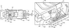
- FIG. 1Ais a side view of a lancing device according to a first example embodiment of the present invention, with a portion of the housing removed to show internal components of the device, showing a latch mechanism for preventing excess lancet oscillation, with the latch in a blocking position.
- FIG. 1Bshows the lancing device of FIG. 1A with the drive mechanism being charged and the latch being pivoted toward an intermediate non-blocking position.
- FIG. 1Cshows the lancing device of FIG. 1B with the latch in the intermediate non-blocking position.
- FIG. 1Dshows the lancing device of FIG. 1C with the lancet traveling along a forward portion of its lancing stroke and the latch pivoted to a press non-blocking position.
- FIG. 1Eshows the lancing device of FIG. 1D with the lancet traveling along a rearward return portion of its lancing stroke and the latch retained in the press non-blocking position.
- FIG. 1Fshows the lancing device of FIG. 1E with the lancet traveling farther along its rearward return portion of its lancing stroke and the latch pivoted back to the blocking position of FIG. 1A .
- FIG. 2Ais a front perspective view of the latch member of the latch mechanism of FIGS. 1A-1F .
- FIG. 2Bis a top view of the latch member of the latch mechanism of FIGS. 1A-1F .
- FIG. 2Cis a rear perspective view of the latch member of the latch mechanism of FIGS. 1A-1F .
- FIG. 3Ashows the lancing device of FIG. 1A with the housing entirely removed to show details of internal components of the latch, charge, and drive mechanisms, with the latch mechanism in the blocking position of FIG. 1A .
- FIG. 3Bis a top view of a portion of the lancing device of FIG. 1A with a top portion of the housing removed to show the internal components, with the latch mechanism in the blocking position of FIG. 1A .
- FIG. 3Cis a front view of the lancing device of FIG. 1A with a front portion of the housing removed to show the internal components, with the latch mechanism in the blocking position of FIG. 1A .
- FIG. 3Dis a front perspective view of the latch mechanism in the blocking position of FIG. 1A , showing details of a detent ramp of the latch mechanism.
- FIG. 3Eis a top view of the latch mechanism of FIG. 3D , showing details of the detent ramp of the latch mechanism.
- FIG. 4is a rear perspective view of the latch member and the detent ramp with the latch mechanism in the position of FIG. 1B .
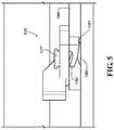
- FIG. 5is a top perspective view of the latch member and the detent ramp with the latch mechanism in the press non-blocking position of FIGS. 1D and 1E .
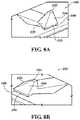
- FIG. 6Ais perspective view of a portion of a latch mechanism according to an alternative embodiment to that shown in FIGS. 1A-5 , with the latch mechanism in the blocking position.
- FIG. 6Bshows the latch mechanism portion of FIG. 6A with the latch mechanism in the intermediate non-blocking position.
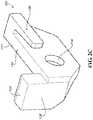
- FIG. 7Ais a front perspective view of a latch member of a latch mechanism of a lancing device according to a second example embodiment of the present invention.
- FIG. 7Bis a rear perspective view of the latch member of FIG. 7A , showing a torsion spring coupled thereto.
- FIG. 7Cis a top view of the latch member of FIG. 7A .
- FIG. 8Ais a rear perspective view of a spring finger of the latch mechanism of FIGS. 7A-7C .
- FIG. 8Bis a front perspective view of the spring finger of FIG. 8A .
- FIG. 9Ais a perspective view of the lancing device with the latch mechanism of FIGS. 7A-8B , with portions removed to show internal components thereof, showing the latch in a blocking position.
- FIG. 9Bshows the lancing device of FIG. 9A with the drive mechanism being charged and the latch pivoted to an intermediate non-blocking position.
- FIG. 9Cshows the lancing device of FIG. 9B with the lancet traveling along a forward portion of its lancing stroke and the latch pivoted to a press non-blocking position.
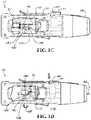
- FIG. 10Ais a side view of the lancing device in the blocking position of FIG. 9A .
- FIG. 10Bis a side view of the lancing device in the intermediate non-blocking position of FIG. 9B .
- FIG. 10Cis a side view of the lancing device in the press non-blocking position of FIG. 9C .
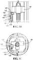
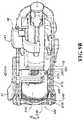
- FIG. 11Ais a cross-sectional view of the lancing device taken at line 11 A- 11 A of FIG. 10A .
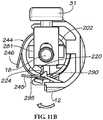
- FIG. 11Bis a cross-sectional view of the lancing device taken at line 11 B- 11 B of FIG. 10B .
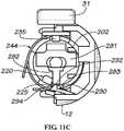
- FIG. 11Cis a cross-sectional view of the lancing device taken at line 11 C- 11 C of FIG. 10C .
- FIGS. 1A-5show a lancing device 10 according to a first example embodiment of the invention.
- the lancing device 10generally includes a drive mechanism 15 , a charging mechanism 30 , a release mechanism 40 , and a housing 12 at least partially enclosing these components.
- the drive mechanism 15includes a drive spring 14 and a return spring 16 for driving a lancet carrier 18 through a lancing stroke.
- the lancet carrier 18removably engages a lancet 20 comprising a lancet body with a sharp lancet tip 22 projecting therefrom.
- the charging mechanism 30operates to retract the lancet carrier 18 from a neutral or normal position to a retracted or charged position to energize the drive spring 14 , and the release mechanism 40 holds the lancet carrier 18 in the retracted position and upon actuation releases the lancet carrier 18 to initiate the lancing stroke.
- the charged drive spring 14propels the lancet carrier 18 and lancet 20 along an advancing/forward portion of the lancing stroke, from the charged position within the housing to an advanced/extended position where at least the sharp lancet tip 22 projects from the housing 12 to penetrate the subject's skin at a lancing site.
- the forward portion of the lancing strokecharges the return spring 16 , and the now-charged return spring then returns the lancet carrier 18 and lancet 20 to the neutral/normal position.
- the housingcan include an endcap or nose-cone portion 50 that provides for adjustment of the penetration depth of the lancet tip 22 . Removal of the endcap 50 also allows access for removal and replacement of the disposal lancet 20 after use, for example, by actuation of a lancet ejection mechanism 60 , in some multi-use designs.
- the lancing device 10includes other conventional drive mechanisms, charging mechanisms, release mechanisms, and/or depth-adjustment mechanisms.
- the drive mechanismcan include a single spring element for driving and retracting
- the charging mechanismcan be provided by a twist-to-charge or push-to-charge mechanism
- the release mechanismcan be provided by a slide or rotary release
- the lancing devicecan include a multi-lancet carrier holding a plurality of lancets for sequential use.
- the lancet carrier 18 and the lancet 20are separates parts, with the lancet being replaceable so that the lancing device 10 can be used multiple times.
- the lancet carrier/holder and the lancetare a single integral component.
- a spring retainer 80 for the drive spring 14 and/or return spring 16is mounted onto and travels with the lancet carrier 18 , and is such considered to be a component of the lancet carrier, even though it could additionally or alternatively be considered to be a component of the drive mechanism.
- reference herein (including the appended claims) to the lancet carrier 18is intended to also refer to the lancet 20 itself as well as to any component of the drive mechanism 15 or another mechanism of the lancing device 10 that travels with the lancet carrier.
- the lancing device 10 of the first embodimentfurther includes a latch mechanism 100 that functions to permit a first oscillation of the lancet carrier 18 and lancet 20 then prevent subsequent (i.e., excess or secondary) oscillations.
- oscillationas used herein is defined as the lancet 20 generally moving from a first/retracted position forward to a second/extended position (i.e., where the lancet tip 22 projects out of the housing 12 to contact the lancing site), and rearward back to or at least toward the first/retracted position (i.e., such that the lancet tip is retracted back into the housing).
- FIGS. 1A-1Fshow details and a sequence of operation of the lancing device 10 with the latch mechanism 100
- FIGS. 2A-5show components of the latch mechanism in greater detail, with FIGS. 3A-3E corresponding to FIGS. 1A and 1 F, with FIG. 4 corresponding to FIG. 1B , and FIG. 5 corresponding to FIGS. 1D and 1E .
- the latch mechanism 100includes a latch member 102 , a latch-pivoting element 135 of the charging mechanism 30 , a latch-engaging element 181 of the lancet carrier 18 , a spring-biased latch retainer 130 of the latch member or other portion of the lancing device 10 , and a ramp 190 of the housing 12 or other portion of the lancing device.
- the latch member 102is pivotally coupled to an element of the lancing device 10 .
- the latch member 102can be pivotally coupled to the housing 12 by a pivot pin 107 with an axis transverse to the angular motion of the latch member 102 , as depicted.
- “pivot”(and other terms with that as the root) includes to rotate or otherwise move angularly.
- the latch member 102 of the depicted embodimentincludes a leg 110 and a foot 120 integrally formed with or attached to the leg and extending at an angle from the leg.
- the foot 120includes at least a portion that extends from the leg 110 in a direction Y that is generally perpendicular to the pivot axis and at least a portion that extends laterally from the leg in a direction X that is generally parallel to the pivot axis.
- the depicted latch member 102is generally L-shaped with the leg 110 having a first end 104 and a second end 105 , and with the foot 120 extending generally perpendicularly and laterally offset from the second end of the leg.
- the foot 120includes a charge-pivot face 122 that is engaged by the latch-pivoting element 135 of the charging mechanism 30 during operation, and a drive-stop face 128 that interferes with the latch-engaging element 181 of the drive mechanism 15 during operation to mechanically block excess oscillation.
- the charge-pivot face 122 and the drive-stop face 128are formed on the portion of the foot 120 that extends in the X and Y direction from the leg 110 and are oppositely facing away from each other.
- the foot 120includes portions that extend in the opposite of the X and Y directions (that is, across the leg faces referenced as 111 and 116 , respectively, in FIG. 2A ) for providing strength and durability.
- the foot 120includes an end face 124 , and a pressing surface 125 typically defined by a corner chamfer extending between the faces 122 and 128 for pressing engagement against the pressed surface 282 of the lancet carrier 18 .
- the spring-biased latch retainer 130is in the form of a resilient finger 130 that is integrally formed with or attached to the leg 110 , the housing 12 , or another element of the lancing device 10 , and that interacts with a rear portion 192 of a ramp 190 (described below).
- the finger 130extends from, and is generally parallel to and laterally offset from the leg 110 on the opposite side from the foot 120 .
- the finger 130extends from the first end 104 of the leg 110 .
- the finger 130includes a contact (e.g., outer) face 132 that engages the ramp 190 when the latch 102 is pivoted through its operating motion.
- the finger 130also includes an opposite (e.g., inner) face 134 that cooperates with a face of the leg 110 to define a slit 136 .
- the finger 130is preferably sufficiently thin and resilient to allow a degree of flexure/deflection toward (as permitted by the slit 136 ) and away from the leg 110 .
- the resilient finger 130functions as a spring to provide a biasing force against the ramp 190 when the two components are moved into engagement with each other.
- the spring-biased latch retaineris in the form of a leaf spring, detent, or other spring-biased element or mechanism.
- the position of the finger 130 and the ramp 190are switched, with the ramp extending outwardly from the latch member 102 and the finger extending inwardly from the housing 12 .
- the leg 110includes a drive-pivot face 111 that is engaged by the latch-engaging element 181 of the drive mechanism 15 during operation.
- the drive-pivot face 111 of the leg 110is laterally offset from and angled relative to the charge-pivot face 122 of the foot 120 , as discussed above.
- the pivotal mounting, and thus the pivot point 107 , of the latch member 102is at the leg 110 .
- the leg 110includes a mounting hole 114 for receiving the pivot pin 107 to attach the latch member 102 to the lancing device 10 and allow the latch member to rotate about an axis A (see FIG. 3E ) generally perpendicular to the advancement and retraction motion of the lancet carrier 18 .
- the pivot pinextends from the latch member and is rotationally received in a mounting hole in the housing 12 or other element of the lancing device 10 .
- the latch-pivoting element 135 of the charging mechanism 30faces generally rearward and moves axially rearward when the charging actuator 31 is actuated to charge the drive mechanism 15 .
- the charging mechanism 30includes an internal member (e.g., the generally wedge-shaped member 37 depicted) extending from the charging actuator 31 and having a surface defining a charging element 33 that engages the drive mechanism 15 to charge the drive spring 14 and also having a surface defining the latch-pivoting element 135 .
- the latch-pivoting element 135is also axially retracted into contact with the charge-pivot face 122 of the foot 120 to pivot the latch member 102 in a first/rearward direction from a blocking position to an intermediate non-blocking position.
- the latch-pivoting element 135is typically ramped, for example it can have an arcuate shape as depicted. Additionally or alternatively, the charge-pivot face 122 of the foot 120 can be ramped, for example arcuate, to induce the latch-pivoting function.
- the latch-engaging element 181 of the lancet carrier 18faces generally forward and moves axially forward with the lancet 20 when the drive mechanism is released/actuated to drive the lancet through the lancing stroke.
- the drive spring 14 and/or return spring 16can be held on the lancet carrier 18 by a spring retainer 80 that is mechanically connected to the lancet carrier, with the spring retainer defining the latch-engaging element 181 (see FIG. 3A ).
- the spring retainer 80has a forward-facing surface defining the latch-engaging element 181 (and also defining a surface that is engaged by the charging element 33 to charge the drive spring 14 ).
- a pressed surface 182 of the lancet carrier 18can be formed for example by a bottom surface of the spring retainer 80 .
- the latch-engaging elementis in the form of a tab or other projection that extends from or attaches to the spring retainer or another element of the drive mechanism.
- the release mechanism 40when the release mechanism 40 is actuated (e.g., by depressing the release actuator 41 ), the lancet carrier 18 is released so it can be propelled by the drive spring 14 through the forward portion of the lancing stroke and at the same time the latch-engaging element 181 is propelled into contact with the drive-pivot face 111 of the leg 110 to pivot the latch member 102 in a second/forward direction from the intermediate non-blocking position back toward the blocking position.
- the release mechanism 40when the release mechanism 40 is actuated (e.g., by depressing the release actuator 41 ), the lancet carrier 18 is released so it can be propelled by the drive spring 14 through the forward portion of the lancing stroke and at the same time the latch-engaging element 181 is propelled into contact with the drive-pivot face 111 of the leg 110 to pivot the latch member 102 in a second/forward direction from the intermediate non-blocking position back toward the blocking position.
- the ramp 190extends inwardly from the housing 12 or other portion of the device 10 .
- the ramp 190has a front ramped portion 191 that is engaged by the deflected resilient finger (or another type of spring-biased latch retainer) 130 when the drive mechanism 15 propels the lancet carrier 18 through the drive/forward portion of the lancing stroke to cooperatively induce the latch 102 to pivot to the blocking position.
- a latch spring biasing the latch 102 from the press non-blocking position to the blocking positionis provided by the resilient finger 130 interacting with the front portion 191 of the ramp 190 . That is, the deflected resilient finger 130 is biased to resiliently return to its neutral position, and as it so discharges it biases against the front ramped portion 191 .
- the ramp 190also includes a rear ramped portion 192 that is engaged by the deflected resilient finger 130 when the charging actuator 31 is axially retracted to cooperatively induce the latch 102 to pivot to and be retained in the intermediate non-blocking position.
- the spring-biased latch retainer 130is provided by the resilient finger interacting with the rear portion 192 of the ramp 190 .
- the ramp 190urges the latch 102 to remain in either the blocked or intermediate non-blocked position when the latch is not in contact with the latch-engaging element 181 or the latch-pivoting element 135 .
- the ramp 190is arcuate and elongated, and it includes a tipping point 193 between the front and rear ramped portions 191 and 192 .
- the ramp 190is outwardly extending/facing from/on an extension (e.g., extending from the housing 12 ) such that it contacts the inner face 134 of the resilient finger 130 and deflects outwardly (away from the latch member) from its neutral state to its charged state, as depicted in FIGS. 6A-6B , respectively.
- the pivot point 107can be located on the extension defining the ramp 190 .
- friction between a feature on the housing 12 or other portion of device 10 and the resilient finger 130may be used to hold the latch member 102 in the blocking or intermediate non-blocking position, or the ramp 190 is eliminated and the latch member is urged to the blocking and intermediate non-blocking positions by gravity or other spring-biased latch retaining mechanisms or elements.
- FIGS. 1A-1FIn a normal (e.g., neutral) state ( FIG. 1A , see also FIGS. 3A-3E ), the latch member 102 is in the blocking (leg-down/foot-up) position with the leg 110 lowered and generally aligned with the axis of translation of the lancet carrier 18 , the blocking foot 120 raised and generally upright relative to the leg, and the finger 130 (and/or the leg) resting on a rib or shelf 194 of the housing 12 . As the charging actuator 31 is retracted (as indicated by the linear-motion arrow in FIG.
- the latch-pivoting element 135 of the charging mechanism 30slides rearwardly against the charge-pivot face 122 of the foot 120 of the latch member 102 , pivoting it (e.g., counter-clockwise as indicated by the angular-motion arrow in FIG. 1B ) about the pivot pin 107 (see also FIG. 4 ).
- Retraction of the charging actuator 31also retracts the lancet carrier 18 and the drive mechanism 15 by contact between the charging element or shoulder 33 (of the internal component 37 of the charging mechanism 30 ) and lancet carrier (e.g., the spring retainer 80 mounted at the distal end of the lancet carrier).
- the latch member 102pivots further, the foot 120 is lowered into a substantially horizontal orientation and the leg 110 is raised to a substantially upright orientation until the latch member is in the intermediate non-blocking (foot-down/leg-up) position ( FIG. 1C ).
- the lancing device 10is now in the charged state with the latch mechanism 100 in the intermediate non-blocking position.
- the outer face 132 of the finger 130is pivoted into contact with the front ramped portion 191 of the ramp 190 (e.g., extending inward from the housing 12 ) to deflect the finger inward (toward the leg 110 ).
- the outer face 132 of the finger 130moves past the tipping point 193 and onto the rear ramped portion 192 of the ramp 190 .
- the biasing force of the deflected finger 130 against the rear ramped portion 192urges the latch member 102 all the way to the intermediate non-blocking position even if it has not been pivoted all the way there by the engagement of the latch-pivoting element 135 and the foot 120 .
- the finger 130has cleared the ramp 190 and resiliently deflected back out to retain the latch member in place.
- the lancing device 10when the lancing device 10 is actuated by operation of the release mechanism 40 , for example by depressing the release actuator 41 (as indicated by the vertical-motion arrow), the discharging of the drive spring 14 drives the lancet carrier 18 and the attached spring retainer 80 forward to propel the lancet carrier through the drive/forward portion of the lancing stroke (as indicated by the horizontal-motion arrow).
- the spring retainer 80As the spring retainer 80 translates forward, it passes over the lowered foot 120 of the latch member 102 until its latch-engaging surface 181 contacts and pushes drive-pivot face 111 of the leg 110 , which causes the latch member to reverse rotate (e.g., clockwise as indicated by the angular-motion arrow in FIG. 1D ), thereby lowering the leg 110 and raising the blocking foot 120 . In this way, the latch member 102 is pivoted from the intermediate non-blocking position back toward the blocking position.
- the lancet carrier 18 and lancet 20come to their fully extended/forward lancing position before the spring retainer 80 has pivoted the latch member 102 all the way back to the blocking position to avoid imparting vibrations to the lancet while puncturing the skin, as shown in FIG. 1D .
- the finger 130remains deflected and engaged on the front ramped portion 191 of the ramp 190 , biasing the latch member 102 toward the blocking position (see also FIG. 5 ).
- the latch member 102is restrained from completing its full pivotal movement and held in this press non-blocking position (between the intermediate non-blocking and blocking positions) because the pressed surface 282 of the lancet carrier (e.g., of the spring retainer 80 or another element of the lancet carrier or drive mechanism 15 ) interferes with pressing surface 125 of the foot 120 (e.g., the latch chamfered face).
- the spring retainer 80has a length such that it does not clear the space above the foot 120 when the lancet carrier 18 and the lancet 20 come to their fully extended/forward lancing position (see FIG. 1D ).
- the return spring 16then returns the lancet carrier 18 from the extended/forward position back through the return/reverse portion of the lancing stroke (as indicated by the linear-motion arrow of FIG. 1E ) toward the normal (e.g., neutral) position, with the spring retainer 80 retracting over the blocking foot 120 in its press non-blocking position ( FIG. 1E ). Because the charging mechanism 30 is not again being actuated, its latch-pivoting element 135 is not retracted to push the latch member 102 back to the intermediate non-blocking position.
- the latch member 102is now free to pivot to the blocking position, and the charged finger 130 discharges against the front ramp surface 191 to return the latch member to its blocking (leg-down/foot-up) position of FIG. 1F (see also FIGS. 1A and 3A-3E ).
- the upright-positioned foot 120then blocks the spring retainer 80 from passing forward again under the force of the drive spring 14 , thereby arresting any further/excess/secondary oscillation of the drive mechanism 15 and preventing the lancet tip 22 from subsequent advancement and potential re-contact with the lancing site.
- a lancet-ejection mechanism 60there is also provided a lancet-ejection mechanism 60 .
- the endcap 50 of the lancing device 10When the endcap 50 of the lancing device 10 is installed on the housing 12 , abutment of an extension 62 of the ejection mechanism 60 against the cap prevents actuation of the ejection mechanism.
- the cap 50To eject the lancet, the cap 50 is removed to allow the ejection mechanism 60 to advance.
- an ejection finger 64 of the ejection mechanismcontacts the lancet 20 through a slot in the lancet carrier 18 to eject the lancet from the lancet carrier in a forward direction (see FIG. 1F ).
- the ejection mechanismis eliminated (i.e., for disposable lancing devices) or provided in another conventional form.
- FIGS. 7A-11Cshow the lancing device 10 as substantially described above, except including a latch mechanism 200 according to a second example embodiment of the present invention.
- the latch mechanism 200includes a latch member 202 , a spring-biased latch retainer 290 , a latch-pivoting element 235 of the charging mechanism 30 , and a latch-engaging element 281 , a pressed surface 282 , and a blocking surface 283 of the lancet carrier 18 , that cooperatively function to produce a substantially similar result to that of the first embodiment.
- a first forward and rearward oscillation of the lancet 20is permitted when the latch member 202 is in intermediate and press non-blocking positions, and subsequent/excess/secondary oscillations are prevented when the latch mechanism is in a blocking position.
- the latch member 202pivots (rotates) between the blocking and non-blocking positions about an axis B ( FIG. 7C ) that is parallel (e.g., coaxial) with the linear advancement and retraction motion of the lancet carrier 18 during the lancing stroke.
- FIGS. 7A-7Cshow details of the sleeve latch member 202 .
- the latch member 202is typically in the form of a cylindrical or tubular sleeve that pivots (rotates) about an axis, though it can be in the form of a curved wall section that does not define a complete circle/cylinder.
- the latch member 202includes a sleeve body 210 extending from a first end 204 to a second end 205 and defining a retainer-biasing surface 223 , an anti-pivot surface 224 , a pressing surface 225 , a drive-stop surface 228 , and a charge-pivot cam surface 222 .
- the latch member 202includes a spring 244 that pivotally (i.e., rotationally) biases it in an angular direction.
- the anti-pivot surface 224is formed on an axial/radial side of the sleeve body 210 and engages the spring-biased latch retainer 290 .
- the sleeve body 210includes a tooth (e.g., a tab, wedge, post, or other projection) 212 that is integrally formed with or attached to it and that has at least a portion extending generally axially therefrom, with the anti-pivot surface 224 formed on an axial/radial side of the tooth.
- the anti-pivot surface 224 of the tooth 212is angled (with respect to a radius line) or otherwise formed to accommodate interaction with the spring-biased latch retainer 290 .
- the anti-pivot surface 224can be angled so that when the sleeve body 210 is pivoted into the non-blocking position, it is flush with the catch surface 295 of the spring biased latch retainer 290 .
- the retainer-biasing surface 223is formed on the sleeve body 210 and engages the spring-biased latch retainer 290 .
- the sleeve body 210includes the tooth 212
- the retainer-biasing surface 223is formed on the outer surface of the tooth of the sleeve body.
- the spring-biased latch retainer 290contacts the retainer-biasing surface 223 when the latch member 202 is in the blocking position and the spring-biased latch retainer is in the charged position, with this contact retaining the latch retainer in the charged position (see FIGS. 9A, 10A, and 11A ).
- the pressing surface 225is formed on an axial/radial side of the sleeve body 210 and engages the pressed surface 282 of the lancet carrier 18 .
- the drive-stop surface 228is formed on the rear side (transverse to the axial/radial side) of the sleeve body 210 and engages the latch-engaging surface 281 of the lancet carrier 18 .
- the sleeve body 210includes a foot (e.g., a tooth, tab, post, wedge, or other projection) 220 that is integrally formed with or attached to it and that extends generally transversely and radially inward therefrom (e.g., from the tooth 212 or adjacent the tooth), with the pressing surface 225 formed on an axial/radial side of the foot and the drive-stop surface 228 is formed on the rear side of the foot.
- the pressing surface 225provides a sufficient contact surface for interference engagement with the pressed surface 282 of the lancet carrier 18 when the latch member 202 is in the press non-blocking angular position (see FIGS. 7C, 9C, 10C , and 11 C).
- the charge-pivot surface 222is formed on an axial/radial surface (transverse to the front and rear sides) of the sleeve body 210 and engages the latch-pivoting element 235 of the charging mechanism 30 .
- the sleeve body 210includes a void 250 formed near the first end 204 of the latch member 202 , with the charge-pivot surface 222 defining a portion of the void.
- the charge-pivot surface 222is angled with respect to the axis of the sleeve body 210 so that when the latch-pivoting element 235 of the charging mechanism 30 is moved longitudinally along it the latch member 212 pivots in an angular direction from the blocking position to the intermediate non-blocking position.
- the charge-pivot surface 222is formed on a wedge extending radially outward from the sleeve body 210 , is non-linear to provide for a non-constant pivoting rate, is non-angled (or less angled) with the latch-pivoting element 235 being angled, or is provided in other configurations for providing the functionality described herein.
- the latch spring 244biases the latch member 202 to pivot from the intermediate and press non-blocking positions toward the blocking position.
- the latch spring 244is a torsion spring that is positioned around the sleeve body 210 and mounted to it by a retaining bracket 240 at the second end 205 of the latch member 202 .
- a first arm 245 of the torsion springcan be retained by the retaining bracket 240 and a second arm 246 can engage the housing 12 or another part of the lancing device 10 .
- the latch springis a compression or tension coil spring, a leaf spring, a resiliently deformable member, or another type of spring element that biases the latch member 202 as described herein.
- the latch-pivoting element 235 of the charging mechanism 30engages the charge-pivot cam surface 222 and thereby pivots the latch member from the blocking position to the intermediate non-blocking position when the charging actuator 31 is operated to charge the drive mechanism 15 .
- the latch-pivoting element 235is a pin that extends radially inward from an internal component of the charging mechanism 30 and slides along the charge-pivot surface 222 .
- the latch-pivoting elementis a post, bar, rod, shaft, panel, finger, boss, or another element that engages the charge-pivot cam surface to pivot the latch member 202 as described herein.
- the latch-engaging element 281 and the blocking surface 283 of the lancet carrier 18engage the spring-biased latch retainer 290 , and the pressed surface 282 of the lancet carrier 18 is engaged by the pressing surface 225 of the latch 202 .
- the latch-engaging element 281 , the pressed surface 282 , and the blocking surface 283are contact surfaces formed on forward, lateral, and bottom faces of a spring retainer 80 of the lancet carrier 18 , with the spring retainer retaining the return spring 16 in place on the lancet carrier for charging and discharging.
- these surfacesare defined by one, two, or three other elements of the lancet carrier 18 , whether dedicated element for use only in the latch mechanism or for shared use in other functions of the lancing device.
- FIGS. 8A-8Bshow details of the spring-biased latch retainer 290 of the depicted embodiment, which is in the form of a resilient finger that is biased from a charged non-latch-retaining position to a discharged latch-retaining position.
- the resilient finger 290extends from a stationary element of the lancing device 10 and includes contact surfaces that selectively engage the latch member 202 and the lancet carrier (or an element coupled thereto) 18 to provide for permitting a first lancet oscillation and preventing subsequent oscillations.
- the resilient finger 290is a cantilevered arm with a head at its free end, the arm projecting inwardly from the housing 12 and the head defining the contact surfaces for engaging the latch member 202 and the lancet carrier 18 .
- the contact surfaces of the resilient finger 290include a first surface 292 , second surface 293 , third surface 294 , and fourth surface 295 .
- the first surface 292contacts the latch member 202 , for example the retainer-biasing surface 223 of the tooth 212 of the sleeve body 210 , when the latch member is in the blocking position and the resilient finger 290 is in the charged non-latch-retaining position, with this contact retaining the resilient finger in position (see FIGS. 9A, 10A, and 11A ).
- the first surface 292can also contact the lancet carrier 18 , for example the blocking surface 283 of the spring retainer 80 , when the latch member is in the press non-blocking position and the resilient finger 290 is in the partially charged (e.g., deflected) non-latch-retaining position, with this contact retaining the resilient finger in position (see FIGS. 9C, 10C, and 11C ).
- the fourth surface 295contacts the latch member 202 , for example the anti-pivot surface 224 , when the latch member is in the intermediate non-blocking position and the resilient finger 290 is in the discharged latch-retaining position, with this contact retaining the latch member in the intermediate non-blocking position (see FIGS. 9B, 10B, and 11B ).
- the third surface 294extends between the first and fourth surfaces 292 and 295 and is ramped (e.g., chamfered or beveled) to facilitate smooth movement across the anti-pivot surface 224 (or portions thereof) when the resilient finger 290 is in partially charged positions moving between the charged non-latch-retaining and discharged latch-retaining positions (see FIGS. 9C, 10C, and 11C ).
- the second surface 293contacts the lancet carrier 18 , for example the latch-engaging surface 281 , and is ramped (e.g., chamfered or beveled) so that when the lancet carrier is being propelled forward through the lancing stroke the latch-engaging surface 281 of the lancet carrier rides along the ramped second surface 293 to deflect the resilient finger 290 and thereby withdraw it from the discharged latch-retaining position toward the charged non-latch-retaining position (in positions between the positions of FIGS. 11B and 11C ).
- rampede.g., chamfered or beveled
- the resilient finger 290is fully discharged in the discharged position (that is, in some embodiments the resilient finger can still have a small charge when in the “discharged” position).
- the spring-biased latch retainerinstead of the cantilevered resilient finger, includes a compression or tension coil spring, a torsion spring, a leaf spring, a resiliently deformable member, or another type of spring element, and still includes the contact surfaces that biasingly engage the lancet carrier 18 and the latch member 202 to provide the functionality described herein.
- the latch retaineris not spring-biased and instead is moved between the non-latch-engaging and latch-engaging positions by an additional mechanism or element.
- the latch retaineris eliminated or formed by an element of the charging mechanism 30 so that the charging mechanism temporarily retains the latch 202 in the intermediate position until the lancet carrier 18 moves far-enough forward that the latch member can be released to reverse-pivot to the press non-blocking position.
- FIGS. 9A-9C, 10A-10C, and 11A-11Cshow the operational use of the latch mechanism 200 .
- a normal (e.g., neutral) stateFIGS. 9A, 10A, and 11A
- the latch member 202In a normal (e.g., neutral) state ( FIGS. 9A, 10A, and 11A ), the latch member 202 is in the blocking position with the foot 220 inserted into the lancing stroke path of the lancet carrier 18 (and/or the lancet 20 ).
- the charging actuator 31is retracted (as indicated by the linear-motion arrow in FIGS.
- the latch-pivoting element 235 of the charging mechanism 30slides rearwardly against the ramped charge-pivot cam face 222 of the latch member 202 , pivoting the latch member (e.g., as indicated by the angular-motion arrow in FIGS. 9B and 10B ) about its axis (e.g., the lancing path axis) from its blocking position to its non-blocking position of FIGS. 9B, 10B, and 11B .
- Retraction of the charging actuator 31also retracts the lancet carrier 18 and the drive mechanism 15 by contact between the charging element or rib 33 (of an internal component 37 of the charging mechanism 30 ) and the lancet carrier (e.g., the spring retainer 80 mounted at the distal end of the lancet carrier).
- the lancet carriere.g., the spring retainer 80 mounted at the distal end of the lancet carrier.
- the spring 244begins to transition from a normal (neutral/uncharged or only slightly charged) state to a charged state to bias the latch member 202 back towards the blocking position.
- the retaining bracket 240follows along the spring first arm 245 , and as a result the spring second arm 246 is engaged with an inner portion (e.g., an inner wall surface) of the housing 12 (or another element of the lancing device 10 ), thus charging the torsional spring to bias the latch member 202 towards the blocking position.
- the lancing device 10is now in the charged state with the latch mechanism 200 retained in the intermediate non-blocking position.
- the pivotal movement of the latch mechanism 202 from the blocking position to intermediate non-blocking positionfrees the spring-biased latch retainer 290 (e.g., the resilient finger) to move from the charged non-latch-retaining position to the discharged latch-retaining position.
- the resilient finger 290can be deflected outward with the first finger surface 292 biased against the retainer-biasing surface 223 of the latch body 210 .
- the first finger surface 292is positioned below the tooth 212 and the finger-blocking surface 223 is defined by the outer wall of the tooth of the latch body 210 ( FIGS.
- the resilient finger 290prevents the latch member 200 in the intermediate non-blocking position from reverse pivoting back toward the blocking position.
- the fourth finger surface 295aligns with the anti-pivot surface 224 of the tooth 212 of the latch member 202 in an interference position to prevent such reverse pivoting ( FIGS. 9B, 10B, and 11B ).
- the release mechanism 40is actuated to release the lancet carrier 18 to be propelled through the lancing stroke by the drive mechanism 15 .
- the release actuator 41is depressed (as indicated by the downward linear arrow of FIGS. 9C and 10C ) to disengage mating elements of the release mechanism 40 and the lancet carrier 18 .
- the released lancet carrier 18is then propelled along the forward portion of the lancing stroke by the discharging drive spring 14 .
- the blocking surface 283 of the lancet carrier 18comes into contact with the second finger surface 293 .
- the second finger surface 293is ramped (and/or the blocking surface 283 can be ramped) so that this engagement deflects the resilient finger 290 from the discharged latch-retaining position to a partially charged non-latch-retaining position ( FIGS. 9C, 10C, and 11C ).
- the lancet carrier 18continues blocking the latch member 202 from further reverse-pivoting as it travels forward to the fully extended position to lance the subject's skin and then begins retracting on the reverse portion of the lancing stroke.
- the pressed surface 282 of the lancet carrier 18has a length sufficient to maintain this interference with the pressing surface 225 of the latch member 202 during these segments of the forward and reverse portions of the lancing stroke. Friction caused by contact between the pressed surface 282 (e.g., of the spring retainer 80 ) and the pressing surface 225 (e.g., of the foot 220 ) is substantially small so that the lancing movement is smooth and easy.
- the latch memberthen further reverse-pivots (in the second/reverse angular direction), under the biasing force of the charged spring 244 , back to the blocking position of FIGS. 9A, 10A, and 11A .
- Thiscauses the anti-pivot surface 224 of the latch member 202 to drive against the ramped third surface 294 of the resilient finger 290 to return/deflect the finger to the charged non-latch-retaining position.
- the drive spring 14may be sufficiently re-charged to initiate a subsequent lancet oscillation.
- the blocking drive-stop surface 228 of the latch member 202e.g., of its tooth 220
- the latch-engaging surface 281 of the lancet carriere.g., of its spring retainer 80
- the latch mechanismdoes not include the spring finger 290 (or the surfaces of the latch and other mechanisms of the lancing device that it engages) and instead includes other types of spring-biased latch retainers that retain the latch member in the intermediate non-blocking position but only until the portion of the lancet carrier that the latch presses against moves into an interference position during the forward portion of the lancing stroke.
- the spring-biased latch retaineris a spring-biased plunger (e.g., a spring-biased pin or projection) extending from the latch member (or the housing) for operating similarly to the resilient finger 290 .
- the plungerextends axially from the second end of the latch where it is biased against a portion of the housing.
- the spring-biased plungerrides along the housing as the latch member pivots until it aligns with an anti-pivot pocket (e.g., formed with the housing) in the intermediate non-blocking position, and then the plunger is extended into the pocket under the biasing influence of its spring force, thereby retaining the latch member in the intermediate non-blocking position.
- a plunger-retraction membere.g., of the lancet carrier
- the latch memberreverse-pivots slightly (in the second angular direction) under the biasing force of the charged spring to the press non-blocking position.
- latch mechanismis the same as described above. It will be understood that included within the scope of the invention are other forms of spring or biasing latch-retaining elements that operate to retain the latch member in the intermediate non-blocking position and then release the latch member to reverse-pivot to the press non-blocking position as a part of the overall operation to permit the first forward and rearward oscillation of the lancet and to then prevent subsequent/excess oscillations after the latch member returns to the blocking position.
- the latch member 202pivots in a first angular direction (counter-clockwise when viewed from behind) and a second opposite angular direction (clockwise when viewed from behind) when functioning to permit the first oscillation of the lancet 20 and prevent subsequent oscillations.
- the latch mechanismis configured so that the latch member pivots in opposite directions or pivots in only one angular direction (whether clockwise or counter-clockwise) when functioning to permit the first oscillation of the lancet and prevent subsequent oscillations.
Landscapes
- Health & Medical Sciences (AREA)
- Life Sciences & Earth Sciences (AREA)
- Engineering & Computer Science (AREA)
- Medical Informatics (AREA)
- Physics & Mathematics (AREA)
- Veterinary Medicine (AREA)
- Biophysics (AREA)
- Pathology (AREA)
- Public Health (AREA)
- Biomedical Technology (AREA)
- Heart & Thoracic Surgery (AREA)
- Hematology (AREA)
- Molecular Biology (AREA)
- Surgery (AREA)
- Animal Behavior & Ethology (AREA)
- General Health & Medical Sciences (AREA)
- Dermatology (AREA)
- Pain & Pain Management (AREA)
- Measurement Of The Respiration, Hearing Ability, Form, And Blood Characteristics Of Living Organisms (AREA)
Abstract
Description
Claims (18)
Priority Applications (6)
| Application Number | Priority Date | Filing Date | Title |
|---|---|---|---|
| US15/824,443US10820849B2 (en) | 2011-12-15 | 2017-11-28 | Latch mechanism for preventing lancet oscillation in a lancing device |
| US17/034,888US20210007652A1 (en) | 2011-12-15 | 2020-09-28 | Latch mechanism for preventing lancet oscillation in a lancing device |
| US17/741,517US11564603B2 (en) | 2011-12-15 | 2022-05-11 | Latch mechanism for preventing lancet oscillation in a lancing device |
| US18/091,986US11883171B2 (en) | 2011-12-15 | 2022-12-30 | Latch mechanism for preventing lancet oscillation in a lancing device |
| US18/424,344US12329524B2 (en) | 2011-12-15 | 2024-01-26 | Latch mechanism for preventing lancet oscillation in a lancing device |
| US19/235,070US20250302351A1 (en) | 2011-12-15 | 2025-06-11 | Latch mechanism for preventing lancet oscillation in a lancing device |
Applications Claiming Priority (3)
| Application Number | Priority Date | Filing Date | Title |
|---|---|---|---|
| US201161570894P | 2011-12-15 | 2011-12-15 | |
| US13/655,168US9844331B2 (en) | 2011-12-15 | 2012-10-18 | Latch mechanism for preventing lancet oscillation in a lancing device |
| US15/824,443US10820849B2 (en) | 2011-12-15 | 2017-11-28 | Latch mechanism for preventing lancet oscillation in a lancing device |
Related Parent Applications (1)
| Application Number | Title | Priority Date | Filing Date |
|---|---|---|---|
| US13/655,168ContinuationUS9844331B2 (en) | 2011-12-15 | 2012-10-18 | Latch mechanism for preventing lancet oscillation in a lancing device |
Related Child Applications (1)
| Application Number | Title | Priority Date | Filing Date |
|---|---|---|---|
| US17/034,888ContinuationUS20210007652A1 (en) | 2011-12-15 | 2020-09-28 | Latch mechanism for preventing lancet oscillation in a lancing device |
Publications (2)
| Publication Number | Publication Date |
|---|---|
| US20180078185A1 US20180078185A1 (en) | 2018-03-22 |
| US10820849B2true US10820849B2 (en) | 2020-11-03 |
Family
ID=47148964
Family Applications (7)
| Application Number | Title | Priority Date | Filing Date |
|---|---|---|---|
| US13/655,168Active2036-02-25US9844331B2 (en) | 2011-12-15 | 2012-10-18 | Latch mechanism for preventing lancet oscillation in a lancing device |
| US15/824,443Active2033-04-13US10820849B2 (en) | 2011-12-15 | 2017-11-28 | Latch mechanism for preventing lancet oscillation in a lancing device |
| US17/034,888AbandonedUS20210007652A1 (en) | 2011-12-15 | 2020-09-28 | Latch mechanism for preventing lancet oscillation in a lancing device |
| US17/741,517ActiveUS11564603B2 (en) | 2011-12-15 | 2022-05-11 | Latch mechanism for preventing lancet oscillation in a lancing device |
| US18/091,986ActiveUS11883171B2 (en) | 2011-12-15 | 2022-12-30 | Latch mechanism for preventing lancet oscillation in a lancing device |
| US18/424,344ActiveUS12329524B2 (en) | 2011-12-15 | 2024-01-26 | Latch mechanism for preventing lancet oscillation in a lancing device |
| US19/235,070PendingUS20250302351A1 (en) | 2011-12-15 | 2025-06-11 | Latch mechanism for preventing lancet oscillation in a lancing device |
Family Applications Before (1)
| Application Number | Title | Priority Date | Filing Date |
|---|---|---|---|
| US13/655,168Active2036-02-25US9844331B2 (en) | 2011-12-15 | 2012-10-18 | Latch mechanism for preventing lancet oscillation in a lancing device |
Family Applications After (5)
| Application Number | Title | Priority Date | Filing Date |
|---|---|---|---|
| US17/034,888AbandonedUS20210007652A1 (en) | 2011-12-15 | 2020-09-28 | Latch mechanism for preventing lancet oscillation in a lancing device |
| US17/741,517ActiveUS11564603B2 (en) | 2011-12-15 | 2022-05-11 | Latch mechanism for preventing lancet oscillation in a lancing device |
| US18/091,986ActiveUS11883171B2 (en) | 2011-12-15 | 2022-12-30 | Latch mechanism for preventing lancet oscillation in a lancing device |
| US18/424,344ActiveUS12329524B2 (en) | 2011-12-15 | 2024-01-26 | Latch mechanism for preventing lancet oscillation in a lancing device |
| US19/235,070PendingUS20250302351A1 (en) | 2011-12-15 | 2025-06-11 | Latch mechanism for preventing lancet oscillation in a lancing device |
Country Status (4)
| Country | Link |
|---|---|
| US (7) | US9844331B2 (en) |
| EP (1) | EP2790581B1 (en) |
| CA (1) | CA2857503C (en) |
| WO (1) | WO2013089917A1 (en) |
Families Citing this family (7)
| Publication number | Priority date | Publication date | Assignee | Title |
|---|---|---|---|---|
| CA2857503C (en) | 2011-12-15 | 2020-10-27 | Facet Technologies, Llc | Latch mechanism for preventing lancet oscillation in a lancing device |
| TWI477256B (en)* | 2012-01-19 | 2015-03-21 | Bionime Corp | Lancing device |
| CA2917866C (en)* | 2013-07-08 | 2022-07-19 | Facet Technologies, Llc | Lancet ejection and advancement mechanism for multi-lancet cartridge |
| GB2533620B (en)* | 2014-12-23 | 2018-06-06 | Owen Mumford Ltd | Skin pricking device |
| JP1627345S (en)* | 2018-05-31 | 2019-03-25 | ||
| US11806143B2 (en)* | 2018-09-21 | 2023-11-07 | Actuated Medical, Inc. | Lancing device having anesthetic feature |
| USD910849S1 (en)* | 2019-05-08 | 2021-02-16 | Sterilance Medical (Suzhou) Inc. | Mini-type safety lancet |
Citations (115)
| Publication number | Priority date | Publication date | Assignee | Title |
|---|---|---|---|---|
| US4203446A (en) | 1976-09-24 | 1980-05-20 | Hellige Gmbh | Precision spring lancet |
| US4841985A (en) | 1986-04-21 | 1989-06-27 | Thomas Wanamaker | Blood drawing apparatus |
| US4895147A (en) | 1988-10-28 | 1990-01-23 | Sherwood Medical Company | Lancet injector |
| US4924879A (en) | 1988-10-07 | 1990-05-15 | Brien Walter J O | Blood lancet device |
| US4976724A (en) | 1989-08-25 | 1990-12-11 | Lifescan, Inc. | Lancet ejector mechanism |
| US5196025A (en) | 1990-05-21 | 1993-03-23 | Ryder International Corporation | Lancet actuator with retractable mechanism |
| USD342573S (en) | 1991-12-13 | 1993-12-21 | Ryder International Corporation | Lancet actuator |
| US5282822A (en) | 1993-01-19 | 1994-02-01 | Sherwood Medical Company | Lancet ejector for lancet injector |
| US5318584A (en) | 1992-04-13 | 1994-06-07 | Boehringer Mannheim Gmbh | Blood lancet device for withdrawing blood for diagnostic purposes |
| US5423847A (en) | 1992-09-25 | 1995-06-13 | Amg Medical, Inc. | Safe lancet injector |
| US5464418A (en) | 1993-12-09 | 1995-11-07 | Schraga; Steven | Reusable lancet device |
| US5518004A (en) | 1994-12-12 | 1996-05-21 | Schraga; Steven | Specimen drawing device |
| US5554166A (en) | 1993-06-21 | 1996-09-10 | Boehringer Mannheim Gmbh | Blood lancet device for withdrawing blood for diagnostic purposes |
| WO1997004707A1 (en) | 1995-07-28 | 1997-02-13 | Apls Co., Ltd. | Assembly for adjusting piercing depth of lancet |
| US5613978A (en) | 1996-06-04 | 1997-03-25 | Palco Laboratories | Adjustable tip for lancet device |
| USD379516S (en) | 1996-03-04 | 1997-05-27 | Bayer Corporation | Lancet |
| EP0898936A2 (en) | 1997-07-31 | 1999-03-03 | Bayer Corporation | Blood sampling device with lancet damping system |
| US5916230A (en) | 1997-06-16 | 1999-06-29 | Bayer Corporation | Blood sampling device with adjustable end cap |
| US5951493A (en) | 1997-05-16 | 1999-09-14 | Mercury Diagnostics, Inc. | Methods and apparatus for expressing body fluid from an incision |
| US5984940A (en) | 1997-05-29 | 1999-11-16 | Atrion Medical Products, Inc. | Lancet device |
| US6022366A (en) | 1998-06-11 | 2000-02-08 | Stat Medical Devices Inc. | Lancet having adjustable penetration depth |
| US6045567A (en) | 1999-02-23 | 2000-04-04 | Lifescan Inc. | Lancing device causing reduced pain |
| USD428150S (en) | 1999-02-23 | 2000-07-11 | Lifescan, Inc. | Lancing device |
| US6168606B1 (en) | 1999-11-10 | 2001-01-02 | Palco Labs, Inc. | Single-use lancet device |
| EP1074219A2 (en) | 1999-08-03 | 2001-02-07 | Becton Dickinson and Company | Lancer |
| US6197040B1 (en) | 1999-02-23 | 2001-03-06 | Lifescan, Inc. | Lancing device having a releasable connector |
| WO2001028423A2 (en) | 1999-10-19 | 2001-04-26 | Therasense Inc. | Lancing device and method of sample collection |
| USD444557S1 (en) | 1999-10-19 | 2001-07-03 | Facet Technologies, Llc | Lancing device |
| US6322575B1 (en) | 2000-01-05 | 2001-11-27 | Steven Schraga | Lancet depth adjustment assembly |
| EP1163879A2 (en) | 2000-06-13 | 2001-12-19 | Bayer Corporation | Lancing mechanism |
| US6332871B1 (en) | 1996-05-17 | 2001-12-25 | Amira Medical | Blood and interstitial fluid sampling device |
| US6409740B1 (en) | 1999-10-09 | 2002-06-25 | Roche Diagnostics Gmbh | Blood lancet system for withdrawing blood for diagnostic purposes |
| US6419661B1 (en) | 1999-03-05 | 2002-07-16 | Roche Diagnostics Gmbh | Device for withdrawing blood for diagnostic applications |
| US6451040B1 (en) | 2000-09-01 | 2002-09-17 | Bayer Corporation | Adjustable endcap for lancing device |
| US6514270B1 (en) | 2000-11-10 | 2003-02-04 | Steven Schraga | Single use lancet device |
| US6530937B1 (en) | 2000-01-28 | 2003-03-11 | Stat Medical Devices, Inc. | Adjustable tip for a lancet device and method |
| US6575939B1 (en) | 1998-02-04 | 2003-06-10 | Sanofi-Synthelabo | Device for automatic injection of a dose of medicinal product |
| US6602268B2 (en) | 2000-06-21 | 2003-08-05 | Roche Diagnostics Corporation | Blood lancet system for blood withdrawal for diagnostic purposes |
| US6645219B2 (en) | 2001-09-07 | 2003-11-11 | Amira Medical | Rotatable penetration depth adjusting arrangement |
| US20030212344A1 (en) | 2002-05-09 | 2003-11-13 | Vadim Yuzhakov | Physiological sample collection devices and methods of using the same |
| US20040039302A1 (en) | 2002-08-23 | 2004-02-26 | Yong Pil Kim | Disposable lancing device |
| USD493532S1 (en) | 2002-12-19 | 2004-07-27 | Facet Technologies, Llc | Lancing device |
| US20040162573A1 (en) | 2003-02-19 | 2004-08-19 | Kheiri Mohammad A. | Endcap for lancing device and method of use |
| US6811557B2 (en) | 1998-06-11 | 2004-11-02 | Stat Medical Devices, Inc. | Adjustable length member such as a cap of a lancet device for adjusting penetration depth |
| US20040249405A1 (en) | 2002-04-04 | 2004-12-09 | Motokazu Watanabe | Lancet device |
| US20040254599A1 (en) | 2003-03-25 | 2004-12-16 | Lipoma Michael V. | Method and apparatus for pre-lancing stimulation of puncture site |
| US6858015B2 (en) | 2001-05-05 | 2005-02-22 | Roche Diagnostics Operations, Inc. | Blood withdrawal system |
| US20050085840A1 (en) | 2003-10-15 | 2005-04-21 | Surgilance Pte Ltd | Lancet assembly |
| US20050125017A1 (en) | 2003-12-05 | 2005-06-09 | Paul Kudrna | Lancet device and method |
| US20050125019A1 (en) | 2003-12-05 | 2005-06-09 | Paul Kudrna | Lancet device and method |
| US20050143771A1 (en) | 2003-12-02 | 2005-06-30 | Stout Jeffrey T. | Lancing device with combination depth and activation control |
| US20050159768A1 (en) | 2004-01-15 | 2005-07-21 | Home Diagnostics, Inc. | Lancing device |
| US6929650B2 (en) | 2001-01-12 | 2005-08-16 | Arkray, Inc. | Lancing device |
| US20050234495A1 (en) | 2003-08-15 | 2005-10-20 | Stat Medical Devices, Inc. | Adjustable lancet device and method |
| US20050234492A1 (en) | 2004-03-15 | 2005-10-20 | Tsai Fu H | Lancet device and method of use |
| US6986777B2 (en) | 2002-04-22 | 2006-01-17 | Yong Pil Kim | Automatic lancing device |
| WO2006031535A2 (en) | 2004-09-09 | 2006-03-23 | Bayer Healthcare Llc | Single puncture lancing fixture with depth adjustment and control of contact force |
| US20060100655A1 (en) | 2004-10-28 | 2006-05-11 | Koon-Wah Leong | Combined lancing and auxiliary device |
| US20060100656A1 (en) | 2004-10-28 | 2006-05-11 | Olson Lorin P | Compact lancing device |
| US7105006B2 (en) | 2003-08-15 | 2006-09-12 | Stat Medical Devices, Inc. | Adjustable lancet device and method |
| US20060224172A1 (en) | 2003-08-20 | 2006-10-05 | Facet Technologies, Llc | Blood sampling device |
| USD530424S1 (en) | 2004-02-17 | 2006-10-17 | Roche Diagnostics Operations, Inc. | Meter with docked lancet device |
| US20060247671A1 (en) | 2005-05-02 | 2006-11-02 | Levaughn Richard W | Compact, multi-use micro-sampling device |
| US20060264996A1 (en) | 2003-08-20 | 2006-11-23 | Facet Technologies, Llc | Lancing device with multi-lancet magazine |
| US7150755B2 (en) | 2002-02-21 | 2006-12-19 | Facet Technologies, Llc | Blood sampling device |
| US7175641B1 (en) | 1998-06-11 | 2007-02-13 | Stat Medical Devices, Inc. | Lancet having adjustable penetration depth |
| US20070055298A1 (en) | 2003-05-21 | 2007-03-08 | Arkray, Inc | Inssertion depth-adjustable needle insertion device |
| US20070083222A1 (en) | 2005-06-16 | 2007-04-12 | Stat Medical Devices, Inc. | Lancet device, removal system for lancet device, and method |
| EP1779781A2 (en) | 2005-10-28 | 2007-05-02 | Lifescan Scotland Ltd | Analyte monitoring system with integrated lancing apparatus |
| US20070100364A1 (en) | 2005-10-28 | 2007-05-03 | Sansom Gordon G | Compact lancing apparatus |
| US7223276B2 (en) | 2002-05-28 | 2007-05-29 | Roche Diagnostics Operations, Inc. | Blood removal system |
| US20070173874A1 (en) | 2006-01-20 | 2007-07-26 | Lifescan, Inc. | Method for dampened lancing |
| US7273484B2 (en) | 2003-08-07 | 2007-09-25 | Roche Diagnostics Operations, Inc. | Blood withdrawal system |
| US7288102B2 (en) | 2003-03-20 | 2007-10-30 | Facet Technologies, Llc | Lancing device with decoupled lancet |
| WO2007130830A2 (en) | 2006-04-25 | 2007-11-15 | Facet Technologies, Llc | Lancing device with independent drive core |
| WO2007146913A2 (en) | 2006-06-15 | 2007-12-21 | Abbott Diabetes Care Inc. | Lancets and methods of use |
| US7322998B2 (en) | 1999-03-05 | 2008-01-29 | Roche Diagnostics Gmbh | Device for withdrawing blood for diagnostic applications |
| USD560805S1 (en) | 2006-06-15 | 2008-01-29 | Abbott Diabetes Care Inc. | Lancing device |
| US20080082117A1 (en) | 2003-11-12 | 2008-04-03 | Facet Technologies, Llc | Lancing device |
| USD569975S1 (en) | 2006-06-07 | 2008-05-27 | Becton Dickinson Co | Lancet device |
| US20080147108A1 (en) | 2002-01-31 | 2008-06-19 | Facet Technologies, Llc | Microsampling device with re-use prevention |
| US20080255598A1 (en) | 2003-08-20 | 2008-10-16 | Facet Technologies, Llc | Lancing Device With Replaceable Multi-Lancet Carousel |
| US7438694B2 (en) | 2006-03-07 | 2008-10-21 | Agamatrix, Inc. | Lancing device |
| USD581533S1 (en) | 2005-04-15 | 2008-11-25 | Facet Technologies, Llc | Multi-lancet lancing device |
| USD586465S1 (en) | 2008-05-09 | 2009-02-10 | Lifescan Scotland Limited | Handheld lancing device |
| USD586916S1 (en) | 2008-05-09 | 2009-02-17 | Lifescan Scotland, Ltd. | Handheld lancing device |
| US7494498B2 (en) | 2003-03-24 | 2009-02-24 | Facet Technologies, Llc | Lancing device with floating lancet |
| US7510564B2 (en) | 2003-06-27 | 2009-03-31 | Abbott Diabetes Care Inc. | Lancing device |
| US7621931B2 (en) | 2003-05-20 | 2009-11-24 | Stat Medical Devices, Inc. | Adjustable lancet device and method |
| US7655019B2 (en) | 2003-08-20 | 2010-02-02 | Facet Technologies, Llc | Blood sampling device |
| US7674232B2 (en) | 2002-04-19 | 2010-03-09 | Pelikan Technologies, Inc. | Method and apparatus for penetrating tissue |
| US7678127B2 (en) | 2003-08-20 | 2010-03-16 | Facet Technologies, Llc | Multi-lancet device with sterility cap repositioning mechanism |
| USD612051S1 (en) | 2008-12-18 | 2010-03-16 | Facet Technologies, Llc | Lancing device |
| US7682318B2 (en) | 2001-06-12 | 2010-03-23 | Pelikan Technologies, Inc. | Blood sampling apparatus and method |
| WO2010080584A1 (en) | 2008-12-18 | 2010-07-15 | Facet Technologies, Llc | Lancing device and lancet |
| US7780610B2 (en) | 2000-05-01 | 2010-08-24 | Terumo Kabushiki Kaisha | Component measuring instrument and chip |
| US7833170B2 (en) | 2002-12-13 | 2010-11-16 | Arkray, Inc. | Needle-insertion device |
| US7842060B2 (en) | 2004-12-10 | 2010-11-30 | Roche Diagnostics Operations, Inc. | Lancet device for generating a puncture wound, and lancet drive assembly |
| WO2011050142A1 (en) | 2009-10-22 | 2011-04-28 | Facet Technologies, Llc. | Lancing device with improved guidance assembly |
| US7998161B2 (en) | 2008-07-09 | 2011-08-16 | Guoping Shi | Disposable incision safety lancet |
| US8016847B2 (en) | 2001-07-11 | 2011-09-13 | Arkray, Inc. | Lancet and lancing apparatus |
| US8043318B2 (en) | 2007-02-08 | 2011-10-25 | Stat Medical Devices, Inc. | Push-button lance device and method |
| US8048097B2 (en) | 2001-08-14 | 2011-11-01 | Steven Schraga | Single use lancet assembly |
| US8048098B2 (en) | 2005-07-14 | 2011-11-01 | Bayer Healthcare Llc | Lancing device for one skin puncture |
| US8062268B2 (en) | 2008-01-28 | 2011-11-22 | Shl Group Ab | Injector with thumb operable scroll wheel |
| US8105347B2 (en) | 2004-11-16 | 2012-01-31 | Stat Medical Devices, Inc. | Adjustable disposable/single-use blade lancet device and method |
| US8211036B2 (en) | 2005-05-27 | 2012-07-03 | Stat Medical Devices, Inc. | Disposable lancet device cap with integral lancet and/or test strip and testing device utilizing the cap |
| US8257380B2 (en) | 2004-06-29 | 2012-09-04 | Stat Medical Devices, Inc. | Adjustabable disposable/single-use lancet device and method |
| US8357107B2 (en) | 2004-04-16 | 2013-01-22 | Becton, Dickinson And Company | Blood glucose meter having integral lancet device and test strip storage vial for single handed use and methods for using same |
| US8388639B2 (en) | 2007-08-14 | 2013-03-05 | Owen Mumford Limited | Lancing devices |
| US20130158586A1 (en) | 2011-12-15 | 2013-06-20 | Facet Technologies, Llc | Latch mechanism for preventing lancet oscillation in a lancing device |
| US8469986B2 (en) | 2007-03-30 | 2013-06-25 | Stat Medical Devices, Inc. | Lancet device with combined trigger and cocking mechanism and method |
| US8932313B2 (en) | 2006-05-04 | 2015-01-13 | Roche Diagnostics Operations, Inc. | Blood collection system for collecting blood from a body part for diagnostic purposes |
| US8971982B2 (en) | 2005-01-18 | 2015-03-03 | Stat Medical Devices, Inc. | Cartridge with lancets and testing device using the cartridge |
| US9282918B2 (en) | 2005-01-28 | 2016-03-15 | Stat Medical Devices, Inc. | Multi-lancet unit, method and lancet device using the multi-lancet unit, and method of assembling and/or making the multi-lancet unit |
Family Cites Families (1)
| Publication number | Priority date | Publication date | Assignee | Title |
|---|---|---|---|---|
| CA2786538A1 (en) | 2010-01-13 | 2011-07-21 | Facet Technologies, Llc | Lancing device with improved guidance mechanism |
- 2012
- 2012-10-18CACA2857503Apatent/CA2857503C/enactiveActive
- 2012-10-18EPEP12784169.0Apatent/EP2790581B1/enactiveActive
- 2012-10-18WOPCT/US2012/060847patent/WO2013089917A1/enactiveApplication Filing
- 2012-10-18USUS13/655,168patent/US9844331B2/enactiveActive
- 2017
- 2017-11-28USUS15/824,443patent/US10820849B2/enactiveActive
- 2020
- 2020-09-28USUS17/034,888patent/US20210007652A1/ennot_activeAbandoned
- 2022
- 2022-05-11USUS17/741,517patent/US11564603B2/enactiveActive
- 2022-12-30USUS18/091,986patent/US11883171B2/enactiveActive
- 2024
- 2024-01-26USUS18/424,344patent/US12329524B2/enactiveActive
- 2025
- 2025-06-11USUS19/235,070patent/US20250302351A1/enactivePending
Patent Citations (149)
| Publication number | Priority date | Publication date | Assignee | Title |
|---|---|---|---|---|
| US4203446A (en) | 1976-09-24 | 1980-05-20 | Hellige Gmbh | Precision spring lancet |
| US4841985A (en) | 1986-04-21 | 1989-06-27 | Thomas Wanamaker | Blood drawing apparatus |
| US4924879A (en) | 1988-10-07 | 1990-05-15 | Brien Walter J O | Blood lancet device |
| US4895147A (en) | 1988-10-28 | 1990-01-23 | Sherwood Medical Company | Lancet injector |
| US4976724A (en) | 1989-08-25 | 1990-12-11 | Lifescan, Inc. | Lancet ejector mechanism |
| US5196025A (en) | 1990-05-21 | 1993-03-23 | Ryder International Corporation | Lancet actuator with retractable mechanism |
| USD342573S (en) | 1991-12-13 | 1993-12-21 | Ryder International Corporation | Lancet actuator |
| US5318584A (en) | 1992-04-13 | 1994-06-07 | Boehringer Mannheim Gmbh | Blood lancet device for withdrawing blood for diagnostic purposes |
| USRE35803E (en) | 1992-04-13 | 1998-05-19 | Boehringer Mannheim Gmbh | Blood lancet device for and method withdrawing blood for diagnostic purposes |
| US5423847A (en) | 1992-09-25 | 1995-06-13 | Amg Medical, Inc. | Safe lancet injector |
| US5282822A (en) | 1993-01-19 | 1994-02-01 | Sherwood Medical Company | Lancet ejector for lancet injector |
| US5554166A (en) | 1993-06-21 | 1996-09-10 | Boehringer Mannheim Gmbh | Blood lancet device for withdrawing blood for diagnostic purposes |
| US5464418A (en) | 1993-12-09 | 1995-11-07 | Schraga; Steven | Reusable lancet device |
| US5518004A (en) | 1994-12-12 | 1996-05-21 | Schraga; Steven | Specimen drawing device |
| WO1997004707A1 (en) | 1995-07-28 | 1997-02-13 | Apls Co., Ltd. | Assembly for adjusting piercing depth of lancet |
| US5730753A (en) | 1995-07-28 | 1998-03-24 | Apls Co., Ltd. | Assembly for adjusting pricking depth of lancet |
| USD379516S (en) | 1996-03-04 | 1997-05-27 | Bayer Corporation | Lancet |
| US6332871B1 (en) | 1996-05-17 | 2001-12-25 | Amira Medical | Blood and interstitial fluid sampling device |
| US5613978A (en) | 1996-06-04 | 1997-03-25 | Palco Laboratories | Adjustable tip for lancet device |
| US5951493A (en) | 1997-05-16 | 1999-09-14 | Mercury Diagnostics, Inc. | Methods and apparatus for expressing body fluid from an incision |
| US5984940A (en) | 1997-05-29 | 1999-11-16 | Atrion Medical Products, Inc. | Lancet device |
| US6156050A (en) | 1997-05-29 | 2000-12-05 | Atrion Medical Products, Inc. | Lancet device |
| US5916230A (en) | 1997-06-16 | 1999-06-29 | Bayer Corporation | Blood sampling device with adjustable end cap |
| US5954738A (en) | 1997-07-31 | 1999-09-21 | Bayer Corporation | Blood sampling device with lancet damping system |
| EP0898936A2 (en) | 1997-07-31 | 1999-03-03 | Bayer Corporation | Blood sampling device with lancet damping system |
| US6575939B1 (en) | 1998-02-04 | 2003-06-10 | Sanofi-Synthelabo | Device for automatic injection of a dose of medicinal product |
| US6022366A (en) | 1998-06-11 | 2000-02-08 | Stat Medical Devices Inc. | Lancet having adjustable penetration depth |
| US6156051A (en) | 1998-06-11 | 2000-12-05 | Stat Medical Devices Inc. | Lancet having adjustable penetration depth |
| US7175641B1 (en) | 1998-06-11 | 2007-02-13 | Stat Medical Devices, Inc. | Lancet having adjustable penetration depth |
| US6811557B2 (en) | 1998-06-11 | 2004-11-02 | Stat Medical Devices, Inc. | Adjustable length member such as a cap of a lancet device for adjusting penetration depth |
| US7947057B2 (en) | 1998-06-11 | 2011-05-24 | Stat Medical Devices, Inc. | Lancet having adjustable penetration depth |
| US7311718B2 (en) | 1998-06-11 | 2007-12-25 | Stat Medical Devices Inc. | Lancet having adjustable penetration depth |
| USD428150S (en) | 1999-02-23 | 2000-07-11 | Lifescan, Inc. | Lancing device |
| US6197040B1 (en) | 1999-02-23 | 2001-03-06 | Lifescan, Inc. | Lancing device having a releasable connector |
| US6045567A (en) | 1999-02-23 | 2000-04-04 | Lifescan Inc. | Lancing device causing reduced pain |
| US7322998B2 (en) | 1999-03-05 | 2008-01-29 | Roche Diagnostics Gmbh | Device for withdrawing blood for diagnostic applications |
| US6419661B1 (en) | 1999-03-05 | 2002-07-16 | Roche Diagnostics Gmbh | Device for withdrawing blood for diagnostic applications |
| US7651512B2 (en) | 1999-08-03 | 2010-01-26 | Becton, Dickinson And Company | Lancer |
| EP1074219A2 (en) | 1999-08-03 | 2001-02-07 | Becton Dickinson and Company | Lancer |
| US6558402B1 (en) | 1999-08-03 | 2003-05-06 | Becton, Dickinson And Company | Lancer |
| US6409740B1 (en) | 1999-10-09 | 2002-06-25 | Roche Diagnostics Gmbh | Blood lancet system for withdrawing blood for diagnostic purposes |
| USD444557S1 (en) | 1999-10-19 | 2001-07-03 | Facet Technologies, Llc | Lancing device |
| US20080146966A1 (en) | 1999-10-19 | 2008-06-19 | Therasense, Inc. | Lancing device and method of sample collection |
| WO2001028423A2 (en) | 1999-10-19 | 2001-04-26 | Therasense Inc. | Lancing device and method of sample collection |
| US6283982B1 (en) | 1999-10-19 | 2001-09-04 | Facet Technologies, Inc. | Lancing device and method of sample collection |
| USD447566S1 (en) | 1999-10-19 | 2001-09-04 | Facet Technologies, Llc | Lancing device with transparent endcap |
| US6749618B2 (en) | 1999-10-19 | 2004-06-15 | Therasense, Inc. | Lancing device and method of sample collection |
| US8366729B2 (en) | 1999-10-19 | 2013-02-05 | Abbott Diabetes Care Inc. | Lancing device and method of sample collection |
| US6168606B1 (en) | 1999-11-10 | 2001-01-02 | Palco Labs, Inc. | Single-use lancet device |
| US6887253B2 (en) | 2000-01-05 | 2005-05-03 | Steve Schraga | Lancet depth adjustment assembly |
| US7678126B2 (en) | 2000-01-05 | 2010-03-16 | Steven Schraga | Lancet depth adjustment assembly |
| US6322575B1 (en) | 2000-01-05 | 2001-11-27 | Steven Schraga | Lancet depth adjustment assembly |
| US6530937B1 (en) | 2000-01-28 | 2003-03-11 | Stat Medical Devices, Inc. | Adjustable tip for a lancet device and method |
| US8709032B2 (en) | 2000-01-28 | 2014-04-29 | Stat Medical Devices, Inc. | Adjustable tip for a lancet device and method |
| US7780610B2 (en) | 2000-05-01 | 2010-08-24 | Terumo Kabushiki Kaisha | Component measuring instrument and chip |
| EP1163879A2 (en) | 2000-06-13 | 2001-12-19 | Bayer Corporation | Lancing mechanism |
| US6602268B2 (en) | 2000-06-21 | 2003-08-05 | Roche Diagnostics Corporation | Blood lancet system for blood withdrawal for diagnostic purposes |
| US6451040B1 (en) | 2000-09-01 | 2002-09-17 | Bayer Corporation | Adjustable endcap for lancing device |
| US6514270B1 (en) | 2000-11-10 | 2003-02-04 | Steven Schraga | Single use lancet device |
| US6929650B2 (en) | 2001-01-12 | 2005-08-16 | Arkray, Inc. | Lancing device |
| US6858015B2 (en) | 2001-05-05 | 2005-02-22 | Roche Diagnostics Operations, Inc. | Blood withdrawal system |
| US7682318B2 (en) | 2001-06-12 | 2010-03-23 | Pelikan Technologies, Inc. | Blood sampling apparatus and method |
| US8016847B2 (en) | 2001-07-11 | 2011-09-13 | Arkray, Inc. | Lancet and lancing apparatus |
| US8048097B2 (en) | 2001-08-14 | 2011-11-01 | Steven Schraga | Single use lancet assembly |
| US6645219B2 (en) | 2001-09-07 | 2003-11-11 | Amira Medical | Rotatable penetration depth adjusting arrangement |
| US20080147108A1 (en) | 2002-01-31 | 2008-06-19 | Facet Technologies, Llc | Microsampling device with re-use prevention |
| US7150755B2 (en) | 2002-02-21 | 2006-12-19 | Facet Technologies, Llc | Blood sampling device |
| US20040249405A1 (en) | 2002-04-04 | 2004-12-09 | Motokazu Watanabe | Lancet device |
| US7674232B2 (en) | 2002-04-19 | 2010-03-09 | Pelikan Technologies, Inc. | Method and apparatus for penetrating tissue |
| US6986777B2 (en) | 2002-04-22 | 2006-01-17 | Yong Pil Kim | Automatic lancing device |
| US20030212344A1 (en) | 2002-05-09 | 2003-11-13 | Vadim Yuzhakov | Physiological sample collection devices and methods of using the same |
| US7223276B2 (en) | 2002-05-28 | 2007-05-29 | Roche Diagnostics Operations, Inc. | Blood removal system |
| US20040039302A1 (en) | 2002-08-23 | 2004-02-26 | Yong Pil Kim | Disposable lancing device |
| US7833170B2 (en) | 2002-12-13 | 2010-11-16 | Arkray, Inc. | Needle-insertion device |
| USD493532S1 (en) | 2002-12-19 | 2004-07-27 | Facet Technologies, Llc | Lancing device |
| US20040162573A1 (en) | 2003-02-19 | 2004-08-19 | Kheiri Mohammad A. | Endcap for lancing device and method of use |
| US7288102B2 (en) | 2003-03-20 | 2007-10-30 | Facet Technologies, Llc | Lancing device with decoupled lancet |
| US7494498B2 (en) | 2003-03-24 | 2009-02-24 | Facet Technologies, Llc | Lancing device with floating lancet |
| US8142466B2 (en) | 2003-03-24 | 2012-03-27 | Facet Technologies, Llc | Lancing device with floating lancet |
| US20040254599A1 (en) | 2003-03-25 | 2004-12-16 | Lipoma Michael V. | Method and apparatus for pre-lancing stimulation of puncture site |
| US7621931B2 (en) | 2003-05-20 | 2009-11-24 | Stat Medical Devices, Inc. | Adjustable lancet device and method |
| US20070055298A1 (en) | 2003-05-21 | 2007-03-08 | Arkray, Inc | Inssertion depth-adjustable needle insertion device |
| US7510564B2 (en) | 2003-06-27 | 2009-03-31 | Abbott Diabetes Care Inc. | Lancing device |
| US7273484B2 (en) | 2003-08-07 | 2007-09-25 | Roche Diagnostics Operations, Inc. | Blood withdrawal system |
| US8152740B2 (en) | 2003-08-07 | 2012-04-10 | Roche Diagnostics Operations, Inc. | Blood withdrawal system |
| US7905898B2 (en) | 2003-08-15 | 2011-03-15 | Stat Medical Devices, Inc. | Adjustable lancet device and method |
| US20050234495A1 (en) | 2003-08-15 | 2005-10-20 | Stat Medical Devices, Inc. | Adjustable lancet device and method |
| US7105006B2 (en) | 2003-08-15 | 2006-09-12 | Stat Medical Devices, Inc. | Adjustable lancet device and method |
| US20060224172A1 (en) | 2003-08-20 | 2006-10-05 | Facet Technologies, Llc | Blood sampling device |
| US7678127B2 (en) | 2003-08-20 | 2010-03-16 | Facet Technologies, Llc | Multi-lancet device with sterility cap repositioning mechanism |
| US20080255598A1 (en) | 2003-08-20 | 2008-10-16 | Facet Technologies, Llc | Lancing Device With Replaceable Multi-Lancet Carousel |
| US20060264996A1 (en) | 2003-08-20 | 2006-11-23 | Facet Technologies, Llc | Lancing device with multi-lancet magazine |
| US7655019B2 (en) | 2003-08-20 | 2010-02-02 | Facet Technologies, Llc | Blood sampling device |
| US20050085840A1 (en) | 2003-10-15 | 2005-04-21 | Surgilance Pte Ltd | Lancet assembly |
| US20080082117A1 (en) | 2003-11-12 | 2008-04-03 | Facet Technologies, Llc | Lancing device |
| US20100234870A1 (en) | 2003-11-12 | 2010-09-16 | Facet Technologies, Llc | Lancing device |
| US20050143771A1 (en) | 2003-12-02 | 2005-06-30 | Stout Jeffrey T. | Lancing device with combination depth and activation control |
| US20050125017A1 (en) | 2003-12-05 | 2005-06-09 | Paul Kudrna | Lancet device and method |
| US20090030441A1 (en) | 2003-12-05 | 2009-01-29 | Virotek, Llc | Lancet device and method |
| US20050125019A1 (en) | 2003-12-05 | 2005-06-09 | Paul Kudrna | Lancet device and method |
| US20050159768A1 (en) | 2004-01-15 | 2005-07-21 | Home Diagnostics, Inc. | Lancing device |
| USD530424S1 (en) | 2004-02-17 | 2006-10-17 | Roche Diagnostics Operations, Inc. | Meter with docked lancet device |
| US20050234492A1 (en) | 2004-03-15 | 2005-10-20 | Tsai Fu H | Lancet device and method of use |
| US8357107B2 (en) | 2004-04-16 | 2013-01-22 | Becton, Dickinson And Company | Blood glucose meter having integral lancet device and test strip storage vial for single handed use and methods for using same |
| US8257380B2 (en) | 2004-06-29 | 2012-09-04 | Stat Medical Devices, Inc. | Adjustabable disposable/single-use lancet device and method |
| WO2006031535A2 (en) | 2004-09-09 | 2006-03-23 | Bayer Healthcare Llc | Single puncture lancing fixture with depth adjustment and control of contact force |
| US20060100655A1 (en) | 2004-10-28 | 2006-05-11 | Koon-Wah Leong | Combined lancing and auxiliary device |
| US20060100656A1 (en) | 2004-10-28 | 2006-05-11 | Olson Lorin P | Compact lancing device |
| US8105347B2 (en) | 2004-11-16 | 2012-01-31 | Stat Medical Devices, Inc. | Adjustable disposable/single-use blade lancet device and method |
| US7842060B2 (en) | 2004-12-10 | 2010-11-30 | Roche Diagnostics Operations, Inc. | Lancet device for generating a puncture wound, and lancet drive assembly |
| US8971982B2 (en) | 2005-01-18 | 2015-03-03 | Stat Medical Devices, Inc. | Cartridge with lancets and testing device using the cartridge |
| US9282918B2 (en) | 2005-01-28 | 2016-03-15 | Stat Medical Devices, Inc. | Multi-lancet unit, method and lancet device using the multi-lancet unit, and method of assembling and/or making the multi-lancet unit |
| US9289161B2 (en) | 2005-01-28 | 2016-03-22 | Stat Medical Divices, Inc. | Multi-lancet unit, method and lancet device using the multi-lancet unit, and method of assembling and/or making the multi-lancet unit |
| USD581533S1 (en) | 2005-04-15 | 2008-11-25 | Facet Technologies, Llc | Multi-lancet lancing device |
| US20060247671A1 (en) | 2005-05-02 | 2006-11-02 | Levaughn Richard W | Compact, multi-use micro-sampling device |
| US8211036B2 (en) | 2005-05-27 | 2012-07-03 | Stat Medical Devices, Inc. | Disposable lancet device cap with integral lancet and/or test strip and testing device utilizing the cap |
| US20070083222A1 (en) | 2005-06-16 | 2007-04-12 | Stat Medical Devices, Inc. | Lancet device, removal system for lancet device, and method |
| US8048098B2 (en) | 2005-07-14 | 2011-11-01 | Bayer Healthcare Llc | Lancing device for one skin puncture |
| US20070100364A1 (en) | 2005-10-28 | 2007-05-03 | Sansom Gordon G | Compact lancing apparatus |
| EP1779781A2 (en) | 2005-10-28 | 2007-05-02 | Lifescan Scotland Ltd | Analyte monitoring system with integrated lancing apparatus |
| US20070173875A1 (en) | 2006-01-20 | 2007-07-26 | Robert Uschold | Lancing device with dampener |
| US20070173874A1 (en) | 2006-01-20 | 2007-07-26 | Lifescan, Inc. | Method for dampened lancing |
| US7438694B2 (en) | 2006-03-07 | 2008-10-21 | Agamatrix, Inc. | Lancing device |
| WO2007130830A2 (en) | 2006-04-25 | 2007-11-15 | Facet Technologies, Llc | Lancing device with independent drive core |
| US8267950B2 (en) | 2006-04-25 | 2012-09-18 | Facet Technologies, Llc | Lancing device with independent drive core |
| US8932313B2 (en) | 2006-05-04 | 2015-01-13 | Roche Diagnostics Operations, Inc. | Blood collection system for collecting blood from a body part for diagnostic purposes |
| USD569975S1 (en) | 2006-06-07 | 2008-05-27 | Becton Dickinson Co | Lancet device |
| USD560805S1 (en) | 2006-06-15 | 2008-01-29 | Abbott Diabetes Care Inc. | Lancing device |
| US8016848B2 (en) | 2006-06-15 | 2011-09-13 | Abbott Diabetes Care Inc. | Lancets and methods of use |
| US7914547B2 (en) | 2006-06-15 | 2011-03-29 | Abbott Diabetes Care Inc. | Adjustable lancing devices and methods |
| US7909842B2 (en) | 2006-06-15 | 2011-03-22 | Abbott Diabetes Care Inc. | Lancing devices having depth adjustment assembly |
| US7867244B2 (en) | 2006-06-15 | 2011-01-11 | Abbott Diabetes Care Inc. | Lancing devices having lancet ejection assembly |
| WO2007146913A2 (en) | 2006-06-15 | 2007-12-21 | Abbott Diabetes Care Inc. | Lancets and methods of use |
| US7955348B2 (en) | 2006-06-15 | 2011-06-07 | Abbott Diabetes Care Inc. | Lancing devices and methods |
| US8043318B2 (en) | 2007-02-08 | 2011-10-25 | Stat Medical Devices, Inc. | Push-button lance device and method |
| US8469986B2 (en) | 2007-03-30 | 2013-06-25 | Stat Medical Devices, Inc. | Lancet device with combined trigger and cocking mechanism and method |
| US8388639B2 (en) | 2007-08-14 | 2013-03-05 | Owen Mumford Limited | Lancing devices |
| US8062268B2 (en) | 2008-01-28 | 2011-11-22 | Shl Group Ab | Injector with thumb operable scroll wheel |
| USD586916S1 (en) | 2008-05-09 | 2009-02-17 | Lifescan Scotland, Ltd. | Handheld lancing device |
| USD586465S1 (en) | 2008-05-09 | 2009-02-10 | Lifescan Scotland Limited | Handheld lancing device |
| US7998161B2 (en) | 2008-07-09 | 2011-08-16 | Guoping Shi | Disposable incision safety lancet |
| WO2010080584A1 (en) | 2008-12-18 | 2010-07-15 | Facet Technologies, Llc | Lancing device and lancet |
| US8398664B2 (en) | 2008-12-18 | 2013-03-19 | Facet Technologies, Llc | Lancing device and lancet |
| WO2010080585A1 (en) | 2008-12-18 | 2010-07-15 | Facet Technologies, Llc | Lancing device and lancet |
| USD612051S1 (en) | 2008-12-18 | 2010-03-16 | Facet Technologies, Llc | Lancing device |
| US9095293B2 (en) | 2008-12-18 | 2015-08-04 | Facet Technologies, Llc | Lancing device and lancet |
| WO2011050142A1 (en) | 2009-10-22 | 2011-04-28 | Facet Technologies, Llc. | Lancing device with improved guidance assembly |
| US9055899B2 (en) | 2009-10-22 | 2015-06-16 | Facet Technologies, Llc | Lancing device with improved guidance assembly |
| US20130158586A1 (en) | 2011-12-15 | 2013-06-20 | Facet Technologies, Llc | Latch mechanism for preventing lancet oscillation in a lancing device |
Non-Patent Citations (1)
| Title |
|---|
| International Search Report & Written Opinion for PCT/US2012/060847; dated Jan. 23, 2013; 11 pgs. |
Also Published As
| Publication number | Publication date |
|---|---|
| US11564603B2 (en) | 2023-01-31 |
| EP2790581B1 (en) | 2016-06-08 |
| WO2013089917A1 (en) | 2013-06-20 |
| CA2857503A1 (en) | 2013-06-20 |
| CA2857503C (en) | 2020-10-27 |
| US12329524B2 (en) | 2025-06-17 |
| US20180078185A1 (en) | 2018-03-22 |
| US11883171B2 (en) | 2024-01-30 |
| US20250302351A1 (en) | 2025-10-02 |
| US20130158586A1 (en) | 2013-06-20 |
| US20220265182A1 (en) | 2022-08-25 |
| US20240206786A1 (en) | 2024-06-27 |
| US20230144482A1 (en) | 2023-05-11 |
| US20210007652A1 (en) | 2021-01-14 |
| EP2790581A1 (en) | 2014-10-22 |
| US9844331B2 (en) | 2017-12-19 |
Similar Documents
| Publication | Publication Date | Title |
|---|---|---|
| US12329524B2 (en) | Latch mechanism for preventing lancet oscillation in a lancing device | |
| KR102454347B1 (en) | Drive unit for drug delivery device | |
| US8858582B2 (en) | Push activation lancet device | |
| CN101912268B (en) | Puncturing needle cartridge | |
| EP2683306B1 (en) | Sleeve for removable lancet of lancing device | |
| EP1031318A1 (en) | Lancing device causing reduced pain | |
| US9386945B2 (en) | Blood lancing device | |
| EP2653103B1 (en) | Percussion structure of lancing device | |
| US9445761B2 (en) | Lancet ejection and advancement mechanism for multi-lancet cartridge | |
| US20110196261A1 (en) | Lancing device with improved guidance mechanism | |
| US10292634B2 (en) | Depth-adjust mechanism for lancing device | |
| KR101521235B1 (en) | Blood lancet device | |
| HK1118438B (en) | Piercing system for removing a bodily fluid |
Legal Events
| Date | Code | Title | Description |
|---|---|---|---|
| FEPP | Fee payment procedure | Free format text:ENTITY STATUS SET TO UNDISCOUNTED (ORIGINAL EVENT CODE: BIG.); ENTITY STATUS OF PATENT OWNER: SMALL ENTITY | |
| AS | Assignment | Owner name:FACET TECHNOLOGIES, LLC, GEORGIA Free format text:ASSIGNMENT OF ASSIGNORS INTEREST;ASSIGNORS:PUSEY, LAUREN R.;LAMPS, GREG;REEL/FRAME:044257/0845 Effective date:20121218 | |
| FEPP | Fee payment procedure | Free format text:ENTITY STATUS SET TO SMALL (ORIGINAL EVENT CODE: SMAL); ENTITY STATUS OF PATENT OWNER: SMALL ENTITY | |
| STPP | Information on status: patent application and granting procedure in general | Free format text:DOCKETED NEW CASE - READY FOR EXAMINATION | |
| AS | Assignment | Owner name:SIENA LENDING GROUP LLC, CONNECTICUT Free format text:SECURITY INTEREST;ASSIGNOR:FACET TECHNOLOGIES, LLC;REEL/FRAME:046694/0941 Effective date:20180720 | |
| STPP | Information on status: patent application and granting procedure in general | Free format text:NON FINAL ACTION MAILED | |
| STPP | Information on status: patent application and granting procedure in general | Free format text:RESPONSE TO NON-FINAL OFFICE ACTION ENTERED AND FORWARDED TO EXAMINER | |
| STPP | Information on status: patent application and granting procedure in general | Free format text:RESPONSE TO NON-FINAL OFFICE ACTION ENTERED AND FORWARDED TO EXAMINER | |
| STPP | Information on status: patent application and granting procedure in general | Free format text:NOTICE OF ALLOWANCE MAILED -- APPLICATION RECEIVED IN OFFICE OF PUBLICATIONS | |
| STPP | Information on status: patent application and granting procedure in general | Free format text:PUBLICATIONS -- ISSUE FEE PAYMENT VERIFIED | |
| STCF | Information on status: patent grant | Free format text:PATENTED CASE | |
| FEPP | Fee payment procedure | Free format text:MAINTENANCE FEE REMINDER MAILED (ORIGINAL EVENT CODE: REM.); ENTITY STATUS OF PATENT OWNER: SMALL ENTITY | |
| FEPP | Fee payment procedure | Free format text:SURCHARGE FOR LATE PAYMENT, SMALL ENTITY (ORIGINAL EVENT CODE: M2554); ENTITY STATUS OF PATENT OWNER: SMALL ENTITY | |
| MAFP | Maintenance fee payment | Free format text:PAYMENT OF MAINTENANCE FEE, 4TH YR, SMALL ENTITY (ORIGINAL EVENT CODE: M2551); ENTITY STATUS OF PATENT OWNER: SMALL ENTITY Year of fee payment:4 |