US10819271B2 - Height adjustable solar panel mounting assembly with an asymmetric lower bracket - Google Patents
Height adjustable solar panel mounting assembly with an asymmetric lower bracketDownload PDFInfo
- Publication number
- US10819271B2 US10819271B2US15/352,494US201615352494AUS10819271B2US 10819271 B2US10819271 B2US 10819271B2US 201615352494 AUS201615352494 AUS 201615352494AUS 10819271 B2US10819271 B2US 10819271B2
- Authority
- US
- United States
- Prior art keywords
- tilted
- box frame
- spring support
- support ledge
- photovoltaic module
- Prior art date
- Legal status (The legal status is an assumption and is not a legal conclusion. Google has not performed a legal analysis and makes no representation as to the accuracy of the status listed.)
- Active
Links
Images


Classifications
- H—ELECTRICITY
- H02—GENERATION; CONVERSION OR DISTRIBUTION OF ELECTRIC POWER
- H02S—GENERATION OF ELECTRIC POWER BY CONVERSION OF INFRARED RADIATION, VISIBLE LIGHT OR ULTRAVIOLET LIGHT, e.g. USING PHOTOVOLTAIC [PV] MODULES
- H02S20/00—Supporting structures for PV modules
- H02S20/20—Supporting structures directly fixed to an immovable object
- H02S20/22—Supporting structures directly fixed to an immovable object specially adapted for buildings
- H02S20/23—Supporting structures directly fixed to an immovable object specially adapted for buildings specially adapted for roof structures
- F—MECHANICAL ENGINEERING; LIGHTING; HEATING; WEAPONS; BLASTING
- F16—ENGINEERING ELEMENTS AND UNITS; GENERAL MEASURES FOR PRODUCING AND MAINTAINING EFFECTIVE FUNCTIONING OF MACHINES OR INSTALLATIONS; THERMAL INSULATION IN GENERAL
- F16M—FRAMES, CASINGS OR BEDS OF ENGINES, MACHINES OR APPARATUS, NOT SPECIFIC TO ENGINES, MACHINES OR APPARATUS PROVIDED FOR ELSEWHERE; STANDS; SUPPORTS
- F16M13/00—Other supports for positioning apparatus or articles; Means for steadying hand-held apparatus or articles
- F16M13/02—Other supports for positioning apparatus or articles; Means for steadying hand-held apparatus or articles for supporting on, or attaching to, an object, e.g. tree, gate, window-frame, cycle
- F—MECHANICAL ENGINEERING; LIGHTING; HEATING; WEAPONS; BLASTING
- F24—HEATING; RANGES; VENTILATING
- F24S—SOLAR HEAT COLLECTORS; SOLAR HEAT SYSTEMS
- F24S25/00—Arrangement of stationary mountings or supports for solar heat collector modules
- F24S25/60—Fixation means, e.g. fasteners, specially adapted for supporting solar heat collector modules
- F24S25/63—Fixation means, e.g. fasteners, specially adapted for supporting solar heat collector modules for fixing modules or their peripheral frames to supporting elements
- F24S25/632—Side connectors; Base connectors
- F—MECHANICAL ENGINEERING; LIGHTING; HEATING; WEAPONS; BLASTING
- F24—HEATING; RANGES; VENTILATING
- F24S—SOLAR HEAT COLLECTORS; SOLAR HEAT SYSTEMS
- F24S25/00—Arrangement of stationary mountings or supports for solar heat collector modules
- F24S25/60—Fixation means, e.g. fasteners, specially adapted for supporting solar heat collector modules
- F24S25/63—Fixation means, e.g. fasteners, specially adapted for supporting solar heat collector modules for fixing modules or their peripheral frames to supporting elements
- F24S25/634—Clamps; Clips
- F24S25/636—Clamps; Clips clamping by screw-threaded elements
- F—MECHANICAL ENGINEERING; LIGHTING; HEATING; WEAPONS; BLASTING
- F16—ENGINEERING ELEMENTS AND UNITS; GENERAL MEASURES FOR PRODUCING AND MAINTAINING EFFECTIVE FUNCTIONING OF MACHINES OR INSTALLATIONS; THERMAL INSULATION IN GENERAL
- F16B—DEVICES FOR FASTENING OR SECURING CONSTRUCTIONAL ELEMENTS OR MACHINE PARTS TOGETHER, e.g. NAILS, BOLTS, CIRCLIPS, CLAMPS, CLIPS OR WEDGES; JOINTS OR JOINTING
- F16B2/00—Friction-grip releasable fastenings
- F16B2/02—Clamps, i.e. with gripping action effected by positive means other than the inherent resistance to deformation of the material of the fastening
- F16B2/06—Clamps, i.e. with gripping action effected by positive means other than the inherent resistance to deformation of the material of the fastening external, i.e. with contracting action
- F16B2/065—Clamps, i.e. with gripping action effected by positive means other than the inherent resistance to deformation of the material of the fastening external, i.e. with contracting action using screw-thread elements
- F—MECHANICAL ENGINEERING; LIGHTING; HEATING; WEAPONS; BLASTING
- F16—ENGINEERING ELEMENTS AND UNITS; GENERAL MEASURES FOR PRODUCING AND MAINTAINING EFFECTIVE FUNCTIONING OF MACHINES OR INSTALLATIONS; THERMAL INSULATION IN GENERAL
- F16H—GEARING
- F16H25/00—Gearings comprising primarily only cams, cam-followers and screw-and-nut mechanisms
- F16H25/18—Gearings comprising primarily only cams, cam-followers and screw-and-nut mechanisms for conveying or interconverting oscillating or reciprocating motions
- F16H25/20—Screw mechanisms
- Y—GENERAL TAGGING OF NEW TECHNOLOGICAL DEVELOPMENTS; GENERAL TAGGING OF CROSS-SECTIONAL TECHNOLOGIES SPANNING OVER SEVERAL SECTIONS OF THE IPC; TECHNICAL SUBJECTS COVERED BY FORMER USPC CROSS-REFERENCE ART COLLECTIONS [XRACs] AND DIGESTS
- Y02—TECHNOLOGIES OR APPLICATIONS FOR MITIGATION OR ADAPTATION AGAINST CLIMATE CHANGE
- Y02B—CLIMATE CHANGE MITIGATION TECHNOLOGIES RELATED TO BUILDINGS, e.g. HOUSING, HOUSE APPLIANCES OR RELATED END-USER APPLICATIONS
- Y02B10/00—Integration of renewable energy sources in buildings
- Y02B10/10—Photovoltaic [PV]
- Y—GENERAL TAGGING OF NEW TECHNOLOGICAL DEVELOPMENTS; GENERAL TAGGING OF CROSS-SECTIONAL TECHNOLOGIES SPANNING OVER SEVERAL SECTIONS OF THE IPC; TECHNICAL SUBJECTS COVERED BY FORMER USPC CROSS-REFERENCE ART COLLECTIONS [XRACs] AND DIGESTS
- Y02—TECHNOLOGIES OR APPLICATIONS FOR MITIGATION OR ADAPTATION AGAINST CLIMATE CHANGE
- Y02B—CLIMATE CHANGE MITIGATION TECHNOLOGIES RELATED TO BUILDINGS, e.g. HOUSING, HOUSE APPLIANCES OR RELATED END-USER APPLICATIONS
- Y02B10/00—Integration of renewable energy sources in buildings
- Y02B10/20—Solar thermal
- Y—GENERAL TAGGING OF NEW TECHNOLOGICAL DEVELOPMENTS; GENERAL TAGGING OF CROSS-SECTIONAL TECHNOLOGIES SPANNING OVER SEVERAL SECTIONS OF THE IPC; TECHNICAL SUBJECTS COVERED BY FORMER USPC CROSS-REFERENCE ART COLLECTIONS [XRACs] AND DIGESTS
- Y02—TECHNOLOGIES OR APPLICATIONS FOR MITIGATION OR ADAPTATION AGAINST CLIMATE CHANGE
- Y02E—REDUCTION OF GREENHOUSE GAS [GHG] EMISSIONS, RELATED TO ENERGY GENERATION, TRANSMISSION OR DISTRIBUTION
- Y02E10/00—Energy generation through renewable energy sources
- Y02E10/40—Solar thermal energy, e.g. solar towers
- Y02E10/47—Mountings or tracking
- Y—GENERAL TAGGING OF NEW TECHNOLOGICAL DEVELOPMENTS; GENERAL TAGGING OF CROSS-SECTIONAL TECHNOLOGIES SPANNING OVER SEVERAL SECTIONS OF THE IPC; TECHNICAL SUBJECTS COVERED BY FORMER USPC CROSS-REFERENCE ART COLLECTIONS [XRACs] AND DIGESTS
- Y02—TECHNOLOGIES OR APPLICATIONS FOR MITIGATION OR ADAPTATION AGAINST CLIMATE CHANGE
- Y02E—REDUCTION OF GREENHOUSE GAS [GHG] EMISSIONS, RELATED TO ENERGY GENERATION, TRANSMISSION OR DISTRIBUTION
- Y02E10/00—Energy generation through renewable energy sources
- Y02E10/50—Photovoltaic [PV] energy
Definitions
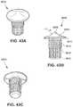
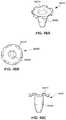
- FIGS. 56A-Cillustrate a twelfth embodiment of a bonding pin in accordance with the principles of the present invention
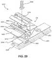
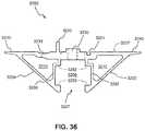
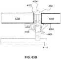
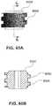
- the lower extension 1332 of the first engagement portion of stanchion 1300engages with an upper extending portion 1531 of bottom plate 1530 .
- the upper extending leg 1333 of stanchion 1300engages with a correspondingly configured lower extending leg 1521 of second ledge 1520 of base 1500 .
- the leg 1334 and ridge 1335 of the second engagement portion of stanchion 1300engages with first ledge 1510 of base 1500 .
- a securement device 1500 Ae.g., a bolt, is threaded through an aperture in the first engagement portion of stanchion 1300 to engage with base 1500 to variably positionably secure the stanchion 1300 at a position along the length of base 1500 .
Landscapes
- Engineering & Computer Science (AREA)
- General Engineering & Computer Science (AREA)
- Mechanical Engineering (AREA)
- Structural Engineering (AREA)
- Civil Engineering (AREA)
- Architecture (AREA)
- Sustainable Development (AREA)
- Combustion & Propulsion (AREA)
- Chemical & Material Sciences (AREA)
- Thermal Sciences (AREA)
- Sustainable Energy (AREA)
- Physics & Mathematics (AREA)
- Life Sciences & Earth Sciences (AREA)
- Photovoltaic Devices (AREA)
- Roof Covering Using Slabs Or Stiff Sheets (AREA)
Abstract
Description
Claims (16)
Priority Applications (1)
| Application Number | Priority Date | Filing Date | Title |
|---|---|---|---|
| US15/352,494US10819271B2 (en) | 2015-08-03 | 2016-11-15 | Height adjustable solar panel mounting assembly with an asymmetric lower bracket |
Applications Claiming Priority (6)
| Application Number | Priority Date | Filing Date | Title |
|---|---|---|---|
| US201562200262P | 2015-08-03 | 2015-08-03 | |
| US201562217580P | 2015-09-11 | 2015-09-11 | |
| US15/138,018US10461682B2 (en) | 2015-08-03 | 2016-04-25 | Height adjustable solar panel mounting assembly |
| US29/580,883USD827157S1 (en) | 2016-10-13 | 2016-10-13 | Base extrusion |
| US29/580,890USD824047S1 (en) | 2016-10-13 | 2016-10-13 | Floating splice extrusion |
| US15/352,494US10819271B2 (en) | 2015-08-03 | 2016-11-15 | Height adjustable solar panel mounting assembly with an asymmetric lower bracket |
Related Parent Applications (1)
| Application Number | Title | Priority Date | Filing Date |
|---|---|---|---|
| US15/138,018Continuation-In-PartUS10461682B2 (en) | 2015-08-03 | 2016-04-25 | Height adjustable solar panel mounting assembly |
Publications (2)
| Publication Number | Publication Date |
|---|---|
| US20170063288A1 US20170063288A1 (en) | 2017-03-02 |
| US10819271B2true US10819271B2 (en) | 2020-10-27 |
Family
ID=58096082
Family Applications (1)
| Application Number | Title | Priority Date | Filing Date |
|---|---|---|---|
| US15/352,494ActiveUS10819271B2 (en) | 2015-08-03 | 2016-11-15 | Height adjustable solar panel mounting assembly with an asymmetric lower bracket |
Country Status (1)
| Country | Link |
|---|---|
| US (1) | US10819271B2 (en) |
Cited By (4)
| Publication number | Priority date | Publication date | Assignee | Title |
|---|---|---|---|---|
| US11336222B1 (en)* | 2021-10-15 | 2022-05-17 | David G. Garza | Universal clamp assembly |
| US20220173692A1 (en)* | 2017-07-25 | 2022-06-02 | Unirac Inc. | Click-On Tower and L-Foot Mount for Attaching Solar Panels to a Roof |
| US11365904B2 (en)* | 2017-06-26 | 2022-06-21 | Unirac Inc. | Multi-level mounting system |
| US12057801B1 (en) | 2023-12-29 | 2024-08-06 | Sunmodo Corporation | Devices and systems for mounting solar panels to metal roofs |
Families Citing this family (15)
| Publication number | Priority date | Publication date | Assignee | Title |
|---|---|---|---|---|
| US10461682B2 (en) | 2015-08-03 | 2019-10-29 | Unirac Inc. | Height adjustable solar panel mounting assembly |
| US10594250B2 (en) | 2015-08-03 | 2020-03-17 | Unirac Inc. | Hybrid solar panel mounting assembly |
| US10819271B2 (en) | 2015-08-03 | 2020-10-27 | Unirac Inc. | Height adjustable solar panel mounting assembly with an asymmetric lower bracket |
| US10211773B2 (en) | 2017-05-24 | 2019-02-19 | Sunmodo Corporation | Height-adjustable solar panel mounting device |
| JP6722924B2 (en)* | 2017-11-01 | 2020-07-15 | 株式会社屋根技術研究所 | Panel member fixing structure and panel member fixing tool |
| US11283395B2 (en) | 2018-03-23 | 2022-03-22 | Nextracker Inc. | Multiple actuator system for solar tracker |
| JP6850010B2 (en)* | 2018-05-30 | 2021-03-31 | 株式会社屋根技術研究所 | Panel member fixing structure and panel member fixing tool |
| US11387771B2 (en) | 2018-06-07 | 2022-07-12 | Nextracker Llc | Helical actuator system for solar tracker |
| WO2020086734A1 (en)* | 2018-10-23 | 2020-04-30 | Pv Solutions, Llc | Devices, methods, and systems for installation of photovoltaic systems |
| US11258400B2 (en)* | 2019-04-16 | 2022-02-22 | Unirac Inc. | Height adjustable solar panel mounting system |
| US11050383B2 (en) | 2019-05-21 | 2021-06-29 | Nextracker Inc | Radial cam helix with 0 degree stow for solar tracker |
| US10797634B1 (en) | 2019-11-27 | 2020-10-06 | Sunmodo Corporation | Height-adjustable rail-less solar panel mounting device for roofs |
| US11441818B2 (en)* | 2020-04-08 | 2022-09-13 | Safeconnect Solar, Inc. | Roof mounted support assembly |
| US11566692B2 (en)* | 2020-12-01 | 2023-01-31 | Gamechange Solar Corp. | Actuator for solar panels |
| WO2025176311A1 (en)* | 2024-02-23 | 2025-08-28 | Eco-Invention Ag | Fastening system for fastening photovoltaic modules, and method for fastening photovoltaic modules using the fastening system |
Citations (87)
| Publication number | Priority date | Publication date | Assignee | Title |
|---|---|---|---|---|
| US3042068A (en) | 1959-04-23 | 1962-07-03 | J E Lonergan Company | Safety relief valve |
| US3269228A (en) | 1964-08-17 | 1966-08-30 | Mack Wilbur | Disc-like socket wrench having laterally pivoting arms |
| US4436005A (en) | 1982-03-10 | 1984-03-13 | Hanson Alan R | Rotary torque adapter |
| USD276879S (en) | 1981-05-11 | 1984-12-25 | Bell Melvin C | Stud adapter for a drill chuck |
| US4822223A (en) | 1987-09-23 | 1989-04-18 | Williams William L | Wood insert |
| US5025750A (en)* | 1987-07-07 | 1991-06-25 | Nylok Fastener Corporation | Apparatus for coating fasteners |
| US5728136A (en) | 1995-06-06 | 1998-03-17 | Thal; Raymond | Knotless suture anchor assembly |
| US5820092A (en) | 1997-02-28 | 1998-10-13 | Thaler; Ken | Modular assembly kit for constructing roof mounted support structures |
| US5927921A (en) | 1997-11-11 | 1999-07-27 | Sps Technologies, Inc. | Enhanced fatigue nut |
| JP2000345664A (en) | 1999-06-08 | 2000-12-12 | Kanegafuchi Chem Ind Co Ltd | Exterior heat insulating structure for roof floor |
| US6361258B1 (en) | 2000-07-06 | 2002-03-26 | Gary V. Heesch | Permanently placeable fasteners, inserter head for fastener placement and related methods |
| US6367258B1 (en) | 1999-07-22 | 2002-04-09 | Bechtel Corporation | Method and apparatus for vaporizing liquid natural gas in a combined cycle power plant |
| US6387129B2 (en) | 1998-03-18 | 2002-05-14 | Arthrex, Inc. | Bicortical tibial fixation of ACL grafts |
| US6457923B1 (en) | 2001-01-17 | 2002-10-01 | Grossman Product Services Sdn. Bhd. | Barrel nut |
| US6478518B1 (en) | 2002-01-31 | 2002-11-12 | Sunny Hwang | Barrel nut |
| US6540750B2 (en) | 1999-05-28 | 2003-04-01 | Stephen S. Burkhart | Suture anchor reel device, kit and method |
| US20060039775A1 (en) | 2002-10-02 | 2006-02-23 | Hiromichi Mizuno | Tapping screw |
| US20080053517A1 (en) | 2006-08-31 | 2008-03-06 | Joshua Reed Plaisted | Technique for electrically bonding solar modules and mounting assemblies |
| US20080067808A1 (en) | 2004-05-28 | 2008-03-20 | Deepak Poddar | Threaded Pipe Joint Coupling With Wire Lock Device |
| USD588893S1 (en) | 2007-02-05 | 2009-03-24 | Gregory John Radich | Drill shroud |
| USD613595S1 (en) | 2008-10-17 | 2010-04-13 | Grand General Accessories Manufacturing | Lug nut cover with a clockwise spiral design |
| USD613594S1 (en) | 2008-10-17 | 2010-04-13 | Grand General Accessories Manufacturing | Lug nut cover with a counterclockwise spiral design |
| US20100192505A1 (en) | 2009-02-05 | 2010-08-05 | D Three Enterprises, Llc | Interlocking Shape For Use in Construction Members |
| US20110000544A1 (en) | 2009-07-02 | 2011-01-06 | West John R | Drop-in connection apparatus, system, and method for photovoltaic arrays |
| US7981143B2 (en) | 2003-09-10 | 2011-07-19 | Spinal Llc | Linear fastener system and method for use |
| US20110203637A1 (en) | 2008-10-11 | 2011-08-25 | Solar Power, Inc. | Efficient Installation Solar Panel Systems |
| US20110260027A1 (en) | 2010-04-23 | 2011-10-27 | Daetwyler-Clean Energy LLC | Solar panel mounting assembly with locking cap |
| US8109048B2 (en) | 2008-02-11 | 2012-02-07 | Zap Solar, Inc. | Apparatus for forming and mounting a photovoltaic array |
| US20120102853A1 (en) | 2010-10-05 | 2012-05-03 | Nathan Rizzo | Mount for pitched roof and method of use |
| US20120102854A1 (en) | 2009-03-27 | 2012-05-03 | Energieburo Ag | Assembly for Fastening a Plurality of Solar Modules to a Building Roof or a Building Facade and Clip for Forming a Stop Element on a Surface |
| US20120192926A1 (en) | 2010-07-20 | 2012-08-02 | Tatsuji Kambara | Solar array |
| US20120234378A1 (en) | 2010-07-02 | 2012-09-20 | John Raymond West | Pivot-Fit Connection Apparatus and System for Photovoltaic Arrays |
| US8272174B2 (en) | 2010-01-25 | 2012-09-25 | Vermont Slate & Copper Services, Inc. | Roofing grommet forming a seal between a roof-mounted structure and a roof |
| US20120301661A1 (en) | 2010-12-09 | 2012-11-29 | John Raymond West | Skirt for Photovoltaic Arrays |
| US20120298817A1 (en)* | 2009-07-02 | 2012-11-29 | John Raymond West | Pivot-Fit Frame, System and Method for Photovoltaic Arrays |
| US20120318322A1 (en) | 2010-02-25 | 2012-12-20 | Empire Technology Development Llc | Solar panel mounting system |
| US8353650B2 (en) | 2006-04-21 | 2013-01-15 | Hubbell Incorporated | Bonding washer |
| US8375645B2 (en) | 2007-03-05 | 2013-02-19 | Niitech Co., Ltd. | Sliding door device |
| US20130048816A1 (en) | 2011-08-31 | 2013-02-28 | Stuart H. Wentworth | Rackless Height Adjustable Mount For Attaching An Article To A Roof |
| US20130048815A1 (en) | 2011-08-30 | 2013-02-28 | General Electric Company | System and method for installation of photovoltaic modules |
| WO2013033404A2 (en) | 2011-09-01 | 2013-03-07 | Sunedison Llc | Solar module mounting bracket and assemblies |
| USD691033S1 (en) | 2012-06-28 | 2013-10-08 | Winzeler Stamping Company | Threaded male collar |
| US8567154B2 (en) | 2012-02-28 | 2013-10-29 | Johns Manville | Apparatus and methods for mounting a photovoltaic module on a roof |
| US8622677B2 (en) | 2007-11-21 | 2014-01-07 | Guangdong Fuwa Engineering Manufacturing Co., Ltd. | Semi-trailer support loading nut |
| USD698637S1 (en) | 2011-11-01 | 2014-02-04 | Cheng-Wei Su | Universal joint |
| US8683761B2 (en) | 2012-06-25 | 2014-04-01 | Sunpower Corporation | Mounting system for solar module array |
| US8695290B1 (en) | 2009-12-07 | 2014-04-15 | Ironridge, Inc. | Systems and methods for splicing solar panel racks |
| US20140109954A1 (en) | 2011-06-03 | 2014-04-24 | Kyocera Corporation | Solar cell array |
| US20140158184A1 (en) | 2011-12-09 | 2014-06-12 | Zep Solar, Inc. | Skirt and Other Devices for Photovoltaic Arrays |
| US8752338B2 (en) | 2012-05-04 | 2014-06-17 | D Three Enterprises, Llc | Adjustable roof mounting system |
| US20140175244A1 (en) | 2011-12-13 | 2014-06-26 | Zep Solar, Inc. | Connecting Components for Photovoltaic Arrays |
| USD713243S1 (en) | 2014-03-07 | 2014-09-16 | Fu-Chuan Hsu | Mounting nut |
| US8935893B2 (en) | 2013-05-31 | 2015-01-20 | Sunmodo Corporation | Direct rooftop mounting apparatus for solar panels |
| US8938932B1 (en) | 2013-12-13 | 2015-01-27 | Quality Product Llc | Rail-less roof mounting system |
| US8943765B2 (en) | 2012-06-25 | 2015-02-03 | Sunpower Corporation | Brace for solar module array |
| US20150034355A1 (en)* | 2013-07-31 | 2015-02-05 | J2L Consulting, LLC | Method and Apparatus For Mounting Solar Panels |
| US20150068590A1 (en) | 2009-10-06 | 2015-03-12 | Zep Solar Llc | Apparatus for forming and mounting a photovoltaic array |
| US9004836B2 (en) | 2010-03-15 | 2015-04-14 | Atomic 22 Limited | Security fastener |
| US9010041B2 (en) | 2012-06-25 | 2015-04-21 | Sunpower Corporation | Leveler for solar module array |
| US20150129517A1 (en) | 2013-11-14 | 2015-05-14 | Ecolibrium Solar, Inc. | Modular Sloped Roof Solar Mounting System |
| US20150188483A1 (en) | 2012-05-31 | 2015-07-02 | Kyocera Corporation | Photovoltaic system and holder unit |
| US9076899B2 (en) | 2013-04-29 | 2015-07-07 | Sunmodo Corporation | Grounding element for solar panel mounting systems |
| US20150204853A1 (en) | 2014-01-06 | 2015-07-23 | Tufts University | Modulators of ion transport proteins or ion channels and methods of identifying and using same |
| US20150204583A1 (en) | 2014-01-22 | 2015-07-23 | Pegasus Solar Inc. | Corner connection bracket for solar energy panels |
| US9097443B2 (en) | 2013-10-15 | 2015-08-04 | Sunmodo Corporation | Solar panel rooftop mounting and grounding device |
| US20150280638A1 (en) | 2014-04-01 | 2015-10-01 | Pegasus Solar Inc. | Mounting assemblies for solar panel systems and methods for using the same |
| US20150288320A1 (en) | 2014-04-07 | 2015-10-08 | Vermont Slate & Copper Services, Inc. | Height adjustment bracket for roof applications |
| USD740866S1 (en) | 2010-04-15 | 2015-10-13 | Eaton Corporation | Face gear |
| US20160111996A1 (en) | 2014-10-20 | 2016-04-21 | Pegasus Solar Inc. | Clamps for securing solar energy panels |
| US20160126884A1 (en) | 2014-10-31 | 2016-05-05 | Vermont Slate & Copper Services, Inc. | Height adjustment bracket for roof applications |
| USD759464S1 (en) | 2010-07-02 | 2016-06-21 | Solarcity Corporation | Leveling foot |
| US20160218661A1 (en) | 2015-01-27 | 2016-07-28 | Ironridge, Inc. | Assembly for locking and grounding solar panel modules to mounting components |
| US20160268958A1 (en) | 2015-03-11 | 2016-09-15 | Ecolibrium Solar, Inc. | Sloped Roof Solar Panel Mounting System |
| US20160268959A1 (en) | 2014-11-19 | 2016-09-15 | Ironridge, Inc. | Rail-Less Solar Panel Assembly and Installation Method |
| US9455662B2 (en) | 2015-01-27 | 2016-09-27 | Ironridge, Inc. | Assembly for locking and grounding solar panel modules to mounting components |
| US20170040931A1 (en) | 2015-08-03 | 2017-02-09 | Unirac, Inc. | Height Adjustable Solar Panel Mounting Assembly |
| USD779308S1 (en) | 2011-12-13 | 2017-02-21 | Solarcity Corporation | Leveling foot |
| US20170063300A1 (en) | 2015-08-31 | 2017-03-02 | Ironridge, Inc. | Apparatus for Securing a Solar Panel Rail Guide to a Support Bracket |
| US20170063288A1 (en) | 2015-08-03 | 2017-03-02 | Unirac Inc. | Height Adjustable Solar Panel Mounting Assembly with an Asymmetric Lower Bracket |
| US20170104442A1 (en) | 2015-03-11 | 2017-04-13 | Ecolibrium Solar, Inc. | Sloped Roof Solar Panel Mounting System |
| US20170155356A1 (en) | 2015-08-03 | 2017-06-01 | Unirac Inc. | Hybrid Solar Panel Mounting Assembly with a Tilted Ledge |
| US20170302221A1 (en) | 2016-04-15 | 2017-10-19 | Sunmodo Corporation | Adjustable End Clamp for Mounting Solar Panels to Roofs |
| US20170299102A1 (en) | 2016-04-14 | 2017-10-19 | Ironridge, Inc. | Conduit Mount Assembly |
| US9800199B2 (en) | 2014-11-19 | 2017-10-24 | Ironridge, Inc. | Roof attachment assembly for solar panels and installation method |
| USD800544S1 (en) | 2016-04-25 | 2017-10-24 | Unirac Inc. | Tri-drive nut |
| US20170366131A1 (en) | 2016-06-21 | 2017-12-21 | Rillito River Solar, Llc | Solar panel mounting system, method and apparatus |
| US20200259448A1 (en) | 2015-08-03 | 2020-08-13 | Unirac Inc. | Hybrid Solar Panel Mounting Assembly |
- 2016
- 2016-11-15USUS15/352,494patent/US10819271B2/enactiveActive
Patent Citations (108)
| Publication number | Priority date | Publication date | Assignee | Title |
|---|---|---|---|---|
| US3042068A (en) | 1959-04-23 | 1962-07-03 | J E Lonergan Company | Safety relief valve |
| US3269228A (en) | 1964-08-17 | 1966-08-30 | Mack Wilbur | Disc-like socket wrench having laterally pivoting arms |
| USD276879S (en) | 1981-05-11 | 1984-12-25 | Bell Melvin C | Stud adapter for a drill chuck |
| US4436005A (en) | 1982-03-10 | 1984-03-13 | Hanson Alan R | Rotary torque adapter |
| US5025750A (en)* | 1987-07-07 | 1991-06-25 | Nylok Fastener Corporation | Apparatus for coating fasteners |
| US4822223A (en) | 1987-09-23 | 1989-04-18 | Williams William L | Wood insert |
| US5728136A (en) | 1995-06-06 | 1998-03-17 | Thal; Raymond | Knotless suture anchor assembly |
| US5820092A (en) | 1997-02-28 | 1998-10-13 | Thaler; Ken | Modular assembly kit for constructing roof mounted support structures |
| US5927921A (en) | 1997-11-11 | 1999-07-27 | Sps Technologies, Inc. | Enhanced fatigue nut |
| US6387129B2 (en) | 1998-03-18 | 2002-05-14 | Arthrex, Inc. | Bicortical tibial fixation of ACL grafts |
| US6540750B2 (en) | 1999-05-28 | 2003-04-01 | Stephen S. Burkhart | Suture anchor reel device, kit and method |
| JP2000345664A (en) | 1999-06-08 | 2000-12-12 | Kanegafuchi Chem Ind Co Ltd | Exterior heat insulating structure for roof floor |
| US6367258B1 (en) | 1999-07-22 | 2002-04-09 | Bechtel Corporation | Method and apparatus for vaporizing liquid natural gas in a combined cycle power plant |
| US6361258B1 (en) | 2000-07-06 | 2002-03-26 | Gary V. Heesch | Permanently placeable fasteners, inserter head for fastener placement and related methods |
| US6457923B1 (en) | 2001-01-17 | 2002-10-01 | Grossman Product Services Sdn. Bhd. | Barrel nut |
| US6478518B1 (en) | 2002-01-31 | 2002-11-12 | Sunny Hwang | Barrel nut |
| US20060039775A1 (en) | 2002-10-02 | 2006-02-23 | Hiromichi Mizuno | Tapping screw |
| US7981143B2 (en) | 2003-09-10 | 2011-07-19 | Spinal Llc | Linear fastener system and method for use |
| US20080067808A1 (en) | 2004-05-28 | 2008-03-20 | Deepak Poddar | Threaded Pipe Joint Coupling With Wire Lock Device |
| US8353650B2 (en) | 2006-04-21 | 2013-01-15 | Hubbell Incorporated | Bonding washer |
| US20080053517A1 (en) | 2006-08-31 | 2008-03-06 | Joshua Reed Plaisted | Technique for electrically bonding solar modules and mounting assemblies |
| US8806813B2 (en) | 2006-08-31 | 2014-08-19 | Pvt Solar, Inc. | Technique for electrically bonding solar modules and mounting assemblies |
| USD588893S1 (en) | 2007-02-05 | 2009-03-24 | Gregory John Radich | Drill shroud |
| US8375645B2 (en) | 2007-03-05 | 2013-02-19 | Niitech Co., Ltd. | Sliding door device |
| US8622677B2 (en) | 2007-11-21 | 2014-01-07 | Guangdong Fuwa Engineering Manufacturing Co., Ltd. | Semi-trailer support loading nut |
| US8109048B2 (en) | 2008-02-11 | 2012-02-07 | Zap Solar, Inc. | Apparatus for forming and mounting a photovoltaic array |
| US20110203637A1 (en) | 2008-10-11 | 2011-08-25 | Solar Power, Inc. | Efficient Installation Solar Panel Systems |
| USD613595S1 (en) | 2008-10-17 | 2010-04-13 | Grand General Accessories Manufacturing | Lug nut cover with a clockwise spiral design |
| USD613594S1 (en) | 2008-10-17 | 2010-04-13 | Grand General Accessories Manufacturing | Lug nut cover with a counterclockwise spiral design |
| US20100192505A1 (en) | 2009-02-05 | 2010-08-05 | D Three Enterprises, Llc | Interlocking Shape For Use in Construction Members |
| US20150013237A1 (en) | 2009-02-05 | 2015-01-15 | D Three Enterprises, Llc | Interlocking shape for use in construction members |
| US20120102854A1 (en) | 2009-03-27 | 2012-05-03 | Energieburo Ag | Assembly for Fastening a Plurality of Solar Modules to a Building Roof or a Building Facade and Clip for Forming a Stop Element on a Surface |
| US8919053B2 (en) | 2009-07-02 | 2014-12-30 | Zep Solar, Llc | Leveling foot apparatus, system, and method for photovoltaic arrays |
| US20110000519A1 (en) | 2009-07-02 | 2011-01-06 | West John R | Pivot-fit connection apparatus, system, and method for photovoltaic modules |
| US20120298817A1 (en)* | 2009-07-02 | 2012-11-29 | John Raymond West | Pivot-Fit Frame, System and Method for Photovoltaic Arrays |
| US20110000544A1 (en) | 2009-07-02 | 2011-01-06 | West John R | Drop-in connection apparatus, system, and method for photovoltaic arrays |
| US20150068590A1 (en) | 2009-10-06 | 2015-03-12 | Zep Solar Llc | Apparatus for forming and mounting a photovoltaic array |
| US8695290B1 (en) | 2009-12-07 | 2014-04-15 | Ironridge, Inc. | Systems and methods for splicing solar panel racks |
| US8272174B2 (en) | 2010-01-25 | 2012-09-25 | Vermont Slate & Copper Services, Inc. | Roofing grommet forming a seal between a roof-mounted structure and a roof |
| US20120318322A1 (en) | 2010-02-25 | 2012-12-20 | Empire Technology Development Llc | Solar panel mounting system |
| US9004836B2 (en) | 2010-03-15 | 2015-04-14 | Atomic 22 Limited | Security fastener |
| USD807419S1 (en) | 2010-04-15 | 2018-01-09 | Eaton Corporation | Face gear |
| USD740866S1 (en) | 2010-04-15 | 2015-10-13 | Eaton Corporation | Face gear |
| US20110260027A1 (en) | 2010-04-23 | 2011-10-27 | Daetwyler-Clean Energy LLC | Solar panel mounting assembly with locking cap |
| US20120234378A1 (en) | 2010-07-02 | 2012-09-20 | John Raymond West | Pivot-Fit Connection Apparatus and System for Photovoltaic Arrays |
| USD759464S1 (en) | 2010-07-02 | 2016-06-21 | Solarcity Corporation | Leveling foot |
| US20120192926A1 (en) | 2010-07-20 | 2012-08-02 | Tatsuji Kambara | Solar array |
| US20120102853A1 (en) | 2010-10-05 | 2012-05-03 | Nathan Rizzo | Mount for pitched roof and method of use |
| US20120301661A1 (en) | 2010-12-09 | 2012-11-29 | John Raymond West | Skirt for Photovoltaic Arrays |
| US20140109954A1 (en) | 2011-06-03 | 2014-04-24 | Kyocera Corporation | Solar cell array |
| US20130048815A1 (en) | 2011-08-30 | 2013-02-28 | General Electric Company | System and method for installation of photovoltaic modules |
| US20130048816A1 (en) | 2011-08-31 | 2013-02-28 | Stuart H. Wentworth | Rackless Height Adjustable Mount For Attaching An Article To A Roof |
| WO2013033404A2 (en) | 2011-09-01 | 2013-03-07 | Sunedison Llc | Solar module mounting bracket and assemblies |
| USD698637S1 (en) | 2011-11-01 | 2014-02-04 | Cheng-Wei Su | Universal joint |
| US20140158184A1 (en) | 2011-12-09 | 2014-06-12 | Zep Solar, Inc. | Skirt and Other Devices for Photovoltaic Arrays |
| USD779308S1 (en) | 2011-12-13 | 2017-02-21 | Solarcity Corporation | Leveling foot |
| US9698724B2 (en) | 2011-12-13 | 2017-07-04 | Solarcity Corporation | Connecting components for photovoltaic arrays |
| US20140175244A1 (en) | 2011-12-13 | 2014-06-26 | Zep Solar, Inc. | Connecting Components for Photovoltaic Arrays |
| US9166524B2 (en) | 2011-12-13 | 2015-10-20 | Solarcity Corporation | Connecting components for photovoltaic arrays |
| USD803664S1 (en) | 2011-12-13 | 2017-11-28 | Solarcity Corporation | Leveling foot |
| US8567154B2 (en) | 2012-02-28 | 2013-10-29 | Johns Manville | Apparatus and methods for mounting a photovoltaic module on a roof |
| US8752338B2 (en) | 2012-05-04 | 2014-06-17 | D Three Enterprises, Llc | Adjustable roof mounting system |
| US20150188483A1 (en) | 2012-05-31 | 2015-07-02 | Kyocera Corporation | Photovoltaic system and holder unit |
| US20160344334A1 (en) | 2012-06-25 | 2016-11-24 | Sunpower Corporation | Leveler for solar module array |
| US9413286B2 (en) | 2012-06-25 | 2016-08-09 | Sunpower Corporation | Leveler for solar module array |
| US8943765B2 (en) | 2012-06-25 | 2015-02-03 | Sunpower Corporation | Brace for solar module array |
| US8683761B2 (en) | 2012-06-25 | 2014-04-01 | Sunpower Corporation | Mounting system for solar module array |
| US9010041B2 (en) | 2012-06-25 | 2015-04-21 | Sunpower Corporation | Leveler for solar module array |
| USD691033S1 (en) | 2012-06-28 | 2013-10-08 | Winzeler Stamping Company | Threaded male collar |
| US9076899B2 (en) | 2013-04-29 | 2015-07-07 | Sunmodo Corporation | Grounding element for solar panel mounting systems |
| US8935893B2 (en) | 2013-05-31 | 2015-01-20 | Sunmodo Corporation | Direct rooftop mounting apparatus for solar panels |
| US9080792B2 (en) | 2013-07-31 | 2015-07-14 | Ironridge, Inc. | Method and apparatus for mounting solar panels |
| US20150244308A1 (en) | 2013-07-31 | 2015-08-27 | Ironridge, Inc. | Lateral Movement Solar Panel Mounting System |
| US20150034355A1 (en)* | 2013-07-31 | 2015-02-05 | J2L Consulting, LLC | Method and Apparatus For Mounting Solar Panels |
| US9097443B2 (en) | 2013-10-15 | 2015-08-04 | Sunmodo Corporation | Solar panel rooftop mounting and grounding device |
| US9825581B2 (en) | 2013-11-14 | 2017-11-21 | Ecolibrium Solar, Inc. | Modular sloped roof solar mounting system |
| US20150129517A1 (en) | 2013-11-14 | 2015-05-14 | Ecolibrium Solar, Inc. | Modular Sloped Roof Solar Mounting System |
| US8938932B1 (en) | 2013-12-13 | 2015-01-27 | Quality Product Llc | Rail-less roof mounting system |
| US9755572B2 (en) | 2013-12-13 | 2017-09-05 | Claudia Wentworth | Rail-less roof mounting system |
| US9712106B2 (en) | 2013-12-13 | 2017-07-18 | Imagineering Plus Plus Llc | Rail-less roof mounting clamp assembly components |
| US20150168021A1 (en) | 2013-12-13 | 2015-06-18 | Quality Product Llc | Rail-less roof mounting clamp assembly |
| US9813012B2 (en) | 2013-12-13 | 2017-11-07 | Quality Product Llc | Rail-less roof mounting clamp assembly |
| US20150204853A1 (en) | 2014-01-06 | 2015-07-23 | Tufts University | Modulators of ion transport proteins or ion channels and methods of identifying and using same |
| US20150204583A1 (en) | 2014-01-22 | 2015-07-23 | Pegasus Solar Inc. | Corner connection bracket for solar energy panels |
| USD713243S1 (en) | 2014-03-07 | 2014-09-16 | Fu-Chuan Hsu | Mounting nut |
| US20150280638A1 (en) | 2014-04-01 | 2015-10-01 | Pegasus Solar Inc. | Mounting assemblies for solar panel systems and methods for using the same |
| US9473066B2 (en) | 2014-04-01 | 2016-10-18 | Pegasus Solar Inc. | Mounting assemblies for solar panel systems and methods for using the same |
| US20150288320A1 (en) | 2014-04-07 | 2015-10-08 | Vermont Slate & Copper Services, Inc. | Height adjustment bracket for roof applications |
| US20160111996A1 (en) | 2014-10-20 | 2016-04-21 | Pegasus Solar Inc. | Clamps for securing solar energy panels |
| US9431953B2 (en) | 2014-10-31 | 2016-08-30 | Rillito River Solar, Llc | Height adjustment bracket for roof applications |
| US20160126884A1 (en) | 2014-10-31 | 2016-05-05 | Vermont Slate & Copper Services, Inc. | Height adjustment bracket for roof applications |
| US9647433B2 (en) | 2014-11-19 | 2017-05-09 | Ironridge, Inc. | Rail-less solar panel assembly and installation method |
| US9800199B2 (en) | 2014-11-19 | 2017-10-24 | Ironridge, Inc. | Roof attachment assembly for solar panels and installation method |
| US20160268959A1 (en) | 2014-11-19 | 2016-09-15 | Ironridge, Inc. | Rail-Less Solar Panel Assembly and Installation Method |
| US20160218661A1 (en) | 2015-01-27 | 2016-07-28 | Ironridge, Inc. | Assembly for locking and grounding solar panel modules to mounting components |
| US9455662B2 (en) | 2015-01-27 | 2016-09-27 | Ironridge, Inc. | Assembly for locking and grounding solar panel modules to mounting components |
| US20160268958A1 (en) | 2015-03-11 | 2016-09-15 | Ecolibrium Solar, Inc. | Sloped Roof Solar Panel Mounting System |
| US20170104442A1 (en) | 2015-03-11 | 2017-04-13 | Ecolibrium Solar, Inc. | Sloped Roof Solar Panel Mounting System |
| US20170155356A1 (en) | 2015-08-03 | 2017-06-01 | Unirac Inc. | Hybrid Solar Panel Mounting Assembly with a Tilted Ledge |
| US20170063288A1 (en) | 2015-08-03 | 2017-03-02 | Unirac Inc. | Height Adjustable Solar Panel Mounting Assembly with an Asymmetric Lower Bracket |
| US20190386602A1 (en) | 2015-08-03 | 2019-12-19 | Unirac Inc. | Height Adjustable Solar Panel Mounting Assembly |
| US20170040931A1 (en) | 2015-08-03 | 2017-02-09 | Unirac, Inc. | Height Adjustable Solar Panel Mounting Assembly |
| US20200259448A1 (en) | 2015-08-03 | 2020-08-13 | Unirac Inc. | Hybrid Solar Panel Mounting Assembly |
| US20170063300A1 (en) | 2015-08-31 | 2017-03-02 | Ironridge, Inc. | Apparatus for Securing a Solar Panel Rail Guide to a Support Bracket |
| US20170299102A1 (en) | 2016-04-14 | 2017-10-19 | Ironridge, Inc. | Conduit Mount Assembly |
| US20170302221A1 (en) | 2016-04-15 | 2017-10-19 | Sunmodo Corporation | Adjustable End Clamp for Mounting Solar Panels to Roofs |
| USD800544S1 (en) | 2016-04-25 | 2017-10-24 | Unirac Inc. | Tri-drive nut |
| US20170366131A1 (en) | 2016-06-21 | 2017-12-21 | Rillito River Solar, Llc | Solar panel mounting system, method and apparatus |
Non-Patent Citations (10)
| Title |
|---|
| http://www.bing.com/images/search?a=security+nut&view=detailv2&&id=4C2424531230A169ADC4DAE0F4EB8EC124253035&selectedIndex=0&ccid=ZLH08zqK&simid=608029617595547726&thid=OIP.M64b1f4f33aBaedc8c63521a0138a6f19o0&ajahist=0, 1 page, retrieved Apr. 1, 2016. |
| http://www.bing.com/images/search?a=square+socket&view=detailv2&&id=1D509F9A8DFCBBB4B007C1E258779F74779A67B&selectedIndex=146&ccid=TiaND%2fol&simid=608049464641849402&thid=OIP.M43568d0ffa089a0070579d68bf010e9bo0&ajaxhist=0, 1 page, retrieved Apr. 1, 2016. |
| http://www.bing.com/images/search?a=tri+drive+nut&view=detailv2&&id=80C4DD5253315F30F57D6691B90DC49F0400179&selectedindex=31&ccid=cbD7XbBT&simid=608041072270839485&thid=OIP.M71b0f5bd053c5ecc513da6b6e2490f0o0&ajaxhist=0, 1 page, retreived Apr. 1, 2016. |
| http://www.bing.com/images/search?a=tri+drive+screw&view=detailv2&&id=DD12BF8073DE72013323056059182C6D86E91F969&selectedindex=30&ccid=j57ZZKxh&simid=607989846202122750&thid=OIP.M8f9ed964ac61774bd32abaf184c076cdo0&ajaxhist=0, 1 page, retrieved Apr. 1, 2016. |
| http://www.bing.com/images/search?a=tri-drive+socket&view=detailv2&&id=6FAC151036BABE696377D989C28380E64C9C21A2&selectedIndex=121&ccid=nm2PL70D&smid=608022930330814765&thid=OIP.M9e6d8fbd03832c834a197be6934bf1o0&ajahist=0, 1 page, retrieved Apr. 1, 2016. |
| https://www.bing.com/images/search?a=tri+drive+nut&view=detailv2&id=80C4DD5253315F30F57D86911690DC49F0400179&selectedindex=31&thid=OIP.M71b0fb5db053c5ecc513dba6b6e2490f0o0&ajaxhist=0&exph=0&expw=0&vt=0&eim=1, 1 page, retrieved Apr. 1, 2016. |
| International Preliminary Report on Patentability issued in PCT Application No. PCT/US2016/045150 dated Feb. 6, 2018 including English translation of document C2 (Japanese-language Written Opinion (PCT/ISA/327 previously filed on (Jan. 4, 2017)) 11 pages. |
| Office Action for U.S. Appl. No. 15/138,030, dated Jun. 27, 2019, Schuit, "Hybrid Solar Panel Mounting Assembly", 10 pages. |
| Office Action for U.S. Appl. No. 15/352,489, dated Oct. 28, 2019, Schuit, "Hybrid Solar Panel Mounting Assembly with a Tilted Ledge", 11 pages. |
| PCT Search Report for corresponding PCT Application No. PCT/US16/45150 dated Dec. 16, 2016, enclosing Written Opinion of the International Searching Authority, 15 pages. |
Cited By (7)
| Publication number | Priority date | Publication date | Assignee | Title |
|---|---|---|---|---|
| US11365904B2 (en)* | 2017-06-26 | 2022-06-21 | Unirac Inc. | Multi-level mounting system |
| US11774144B2 (en) | 2017-06-26 | 2023-10-03 | Unirac Inc. | Multi-level mounting system |
| US12429251B2 (en) | 2017-06-26 | 2025-09-30 | Unirac, Inc. | Multi-level mounting system |
| US20220173692A1 (en)* | 2017-07-25 | 2022-06-02 | Unirac Inc. | Click-On Tower and L-Foot Mount for Attaching Solar Panels to a Roof |
| US12301160B2 (en)* | 2017-07-25 | 2025-05-13 | Unirac, Inc. | Click-on tower and L-foot mount for attaching solar panels to a roof |
| US11336222B1 (en)* | 2021-10-15 | 2022-05-17 | David G. Garza | Universal clamp assembly |
| US12057801B1 (en) | 2023-12-29 | 2024-08-06 | Sunmodo Corporation | Devices and systems for mounting solar panels to metal roofs |
Also Published As
| Publication number | Publication date |
|---|---|
| US20170063288A1 (en) | 2017-03-02 |
Similar Documents
| Publication | Publication Date | Title |
|---|---|---|
| US10819271B2 (en) | Height adjustable solar panel mounting assembly with an asymmetric lower bracket | |
| US11894800B2 (en) | Height adjustable solar panel mounting assembly | |
| US11290053B2 (en) | Solar panel mounting apparatus | |
| US11739785B2 (en) | Trim attachment assembly for mounting solar panel equipment | |
| US12289079B2 (en) | Hybrid solar panel mounting assembly | |
| US11979107B2 (en) | Solar module mounting system | |
| US8752338B2 (en) | Adjustable roof mounting system | |
| US8176693B2 (en) | Photovoltaic mounting system with locking connectors, adjustable rail height and hinge lock | |
| US10340838B2 (en) | Hybrid solar panel mounting assembly with a tilted ledge | |
| US9998065B2 (en) | Trim assembly | |
| US8567030B2 (en) | Apparatus for fastening a mounting rail to a threaded shaft | |
| US8413944B2 (en) | Mounting systems for solar panels | |
| CN106133460A (en) | Mounting assembly for solar panel system and method of using same | |
| EP3336369B1 (en) | Fastening system | |
| US8065843B2 (en) | Cable cleat system | |
| US11106004B2 (en) | Connecting device for focusing lens or aiming lens | |
| US20220349206A1 (en) | Bird Feeder Apparatus | |
| DE102009022780A1 (en) | Stand for solar module, has holder comprising two angle sections that are pivotable opposite to each other around horizontal axis, where one of angle sections has side parts projecting from base, and another section has arms | |
| KR200285519Y1 (en) | Apparatus for readjusting front panel of a sink drawer | |
| GB2474826A (en) | Clamp device | |
| JP5777006B2 (en) | Mounting member, external member mounting structure, and construction method thereof | |
| JP6944261B2 (en) | bracket | |
| WO2024177494A1 (en) | System for securing photovoltaic modules to trapezoidal sheet roofs | |
| JPH11350680A (en) | Coping fixing metal and its fitting method |
Legal Events
| Date | Code | Title | Description |
|---|---|---|---|
| AS | Assignment | Owner name:UNIRAC INC., NEW MEXICO Free format text:ASSIGNMENT OF ASSIGNORS INTEREST;ASSIGNORS:SCHUIT, NATHAN;MAYFIELD, JASON;GALLEGOS, ERNEST;SIGNING DATES FROM 20161108 TO 20161111;REEL/FRAME:040331/0674 | |
| AS | Assignment | Owner name:PNC BANK, NATIONAL ASSOCIATION, AS AGENT, NEW JERSEY Free format text:ASSIGNMENT OF ASSIGNORS INTEREST;ASSIGNOR:UNIRAC, INC., AS GRANTOR;REEL/FRAME:046267/0330 Effective date:20180629 Owner name:PNC BANK, NATIONAL ASSOCIATION, AS AGENT, NEW JERS Free format text:ASSIGNMENT OF ASSIGNORS INTEREST;ASSIGNOR:UNIRAC, INC., AS GRANTOR;REEL/FRAME:046267/0330 Effective date:20180629 | |
| STPP | Information on status: patent application and granting procedure in general | Free format text:RESPONSE TO NON-FINAL OFFICE ACTION ENTERED AND FORWARDED TO EXAMINER | |
| STPP | Information on status: patent application and granting procedure in general | Free format text:FINAL REJECTION MAILED | |
| STPP | Information on status: patent application and granting procedure in general | Free format text:RESPONSE AFTER FINAL ACTION FORWARDED TO EXAMINER | |
| STPP | Information on status: patent application and granting procedure in general | Free format text:ADVISORY ACTION MAILED | |
| STPP | Information on status: patent application and granting procedure in general | Free format text:DOCKETED NEW CASE - READY FOR EXAMINATION | |
| STPP | Information on status: patent application and granting procedure in general | Free format text:NON FINAL ACTION MAILED | |
| STPP | Information on status: patent application and granting procedure in general | Free format text:RESPONSE TO NON-FINAL OFFICE ACTION ENTERED AND FORWARDED TO EXAMINER | |
| STPP | Information on status: patent application and granting procedure in general | Free format text:FINAL REJECTION MAILED | |
| STPP | Information on status: patent application and granting procedure in general | Free format text:NOTICE OF ALLOWANCE MAILED -- APPLICATION RECEIVED IN OFFICE OF PUBLICATIONS | |
| STCF | Information on status: patent grant | Free format text:PATENTED CASE | |
| AS | Assignment | Owner name:LBC CREDIT AGENCY SERVICES, LLC, AS AGENT, PENNSYLVANIA Free format text:SECURITY INTEREST;ASSIGNOR:UNIRAC, INC.;REEL/FRAME:056684/0333 Effective date:20210625 Owner name:UNIRAC, INC., NEW MEXICO Free format text:RELEASE BY SECURED PARTY;ASSIGNOR:PNC BANK, NATIONAL ASSOCIATION, AS AGENT;REEL/FRAME:056684/0379 Effective date:20210625 Owner name:ECOUNI, LLC, NEW MEXICO Free format text:RELEASE BY SECURED PARTY;ASSIGNOR:PNC BANK, NATIONAL ASSOCIATION, AS AGENT;REEL/FRAME:056684/0379 Effective date:20210625 | |
| AS | Assignment | Owner name:LBC CREDIT AGENCY SERVICES, LLC, AS AGENT, PENNSYLVANIA Free format text:SECURITY INTEREST;ASSIGNOR:UNIRAC, INC.;REEL/FRAME:061587/0852 Effective date:20220930 | |
| AS | Assignment | Owner name:UNIRAC, INC., NEW MEXICO Free format text:RELEASE BY SECURED PARTY;ASSIGNOR:LBC CREDIT AGENCY SERVICES, LLC, AS AGENT;REEL/FRAME:061605/0949 Effective date:20220930 | |
| FEPP | Fee payment procedure | Free format text:ENTITY STATUS SET TO UNDISCOUNTED (ORIGINAL EVENT CODE: BIG.); ENTITY STATUS OF PATENT OWNER: LARGE ENTITY | |
| MAFP | Maintenance fee payment | Free format text:PAYMENT OF MAINTENANCE FEE, 4TH YEAR, LARGE ENTITY (ORIGINAL EVENT CODE: M1551); ENTITY STATUS OF PATENT OWNER: LARGE ENTITY Year of fee payment:4 |