US10819174B2 - System and apparatus for segmented axial field rotary energy device - Google Patents
System and apparatus for segmented axial field rotary energy deviceDownload PDFInfo
- Publication number
- US10819174B2 US10819174B2US16/365,120US201916365120AUS10819174B2US 10819174 B2US10819174 B2US 10819174B2US 201916365120 AUS201916365120 AUS 201916365120AUS 10819174 B2US10819174 B2US 10819174B2
- Authority
- US
- United States
- Prior art keywords
- pcb
- stator
- energy device
- axial field
- layer
- Prior art date
- Legal status (The legal status is an assumption and is not a legal conclusion. Google has not performed a legal analysis and makes no representation as to the accuracy of the status listed.)
- Active
Links
Images


Classifications
- H—ELECTRICITY
- H02—GENERATION; CONVERSION OR DISTRIBUTION OF ELECTRIC POWER
- H02K—DYNAMO-ELECTRIC MACHINES
- H02K16/00—Machines with more than one rotor or stator
- H—ELECTRICITY
- H02—GENERATION; CONVERSION OR DISTRIBUTION OF ELECTRIC POWER
- H02K—DYNAMO-ELECTRIC MACHINES
- H02K1/00—Details of the magnetic circuit
- H02K1/06—Details of the magnetic circuit characterised by the shape, form or construction
- H02K1/12—Stationary parts of the magnetic circuit
- H02K1/18—Means for mounting or fastening magnetic stationary parts on to, or to, the stator structures
- H02K1/182—Means for mounting or fastening magnetic stationary parts on to, or to, the stator structures to stators axially facing the rotor, i.e. with axial or conical air gap
- H—ELECTRICITY
- H02—GENERATION; CONVERSION OR DISTRIBUTION OF ELECTRIC POWER
- H02K—DYNAMO-ELECTRIC MACHINES
- H02K1/00—Details of the magnetic circuit
- H02K1/06—Details of the magnetic circuit characterised by the shape, form or construction
- H02K1/22—Rotating parts of the magnetic circuit
- H02K1/27—Rotor cores with permanent magnets
- H02K1/2793—Rotors axially facing stators
- H—ELECTRICITY
- H02—GENERATION; CONVERSION OR DISTRIBUTION OF ELECTRIC POWER
- H02K—DYNAMO-ELECTRIC MACHINES
- H02K3/00—Details of windings
- H02K3/04—Windings characterised by the conductor shape, form or construction, e.g. with bar conductors
- H02K3/26—Windings characterised by the conductor shape, form or construction, e.g. with bar conductors consisting of printed conductors
- H—ELECTRICITY
- H02—GENERATION; CONVERSION OR DISTRIBUTION OF ELECTRIC POWER
- H02K—DYNAMO-ELECTRIC MACHINES
- H02K3/00—Details of windings
- H02K3/04—Windings characterised by the conductor shape, form or construction, e.g. with bar conductors
- H02K3/28—Layout of windings or of connections between windings
- H—ELECTRICITY
- H02—GENERATION; CONVERSION OR DISTRIBUTION OF ELECTRIC POWER
- H02K—DYNAMO-ELECTRIC MACHINES
- H02K3/00—Details of windings
- H02K3/46—Fastening of windings on the stator or rotor structure
- H02K3/47—Air-gap windings, i.e. iron-free windings
- H—ELECTRICITY
- H02—GENERATION; CONVERSION OR DISTRIBUTION OF ELECTRIC POWER
- H02P—CONTROL OR REGULATION OF ELECTRIC MOTORS, ELECTRIC GENERATORS OR DYNAMO-ELECTRIC CONVERTERS; CONTROLLING TRANSFORMERS, REACTORS OR CHOKE COILS
- H02P31/00—Arrangements for regulating or controlling electric motors not provided for in groups H02P1/00 - H02P5/00, H02P7/00 or H02P21/00 - H02P29/00
- H—ELECTRICITY
- H02—GENERATION; CONVERSION OR DISTRIBUTION OF ELECTRIC POWER
- H02K—DYNAMO-ELECTRIC MACHINES
- H02K1/00—Details of the magnetic circuit
- H02K1/06—Details of the magnetic circuit characterised by the shape, form or construction
- H02K1/12—Stationary parts of the magnetic circuit
- H—ELECTRICITY
- H02—GENERATION; CONVERSION OR DISTRIBUTION OF ELECTRIC POWER
- H02K—DYNAMO-ELECTRIC MACHINES
- H02K1/00—Details of the magnetic circuit
- H02K1/06—Details of the magnetic circuit characterised by the shape, form or construction
- H02K1/22—Rotating parts of the magnetic circuit
- H02K1/27—Rotor cores with permanent magnets
- H02K1/2706—Inner rotors
- H02K1/272—Inner rotors the magnetisation axis of the magnets being perpendicular to the rotor axis
- H02K1/274—Inner rotors the magnetisation axis of the magnets being perpendicular to the rotor axis the rotor consisting of two or more circumferentially positioned magnets
- H02K1/2753—Inner rotors the magnetisation axis of the magnets being perpendicular to the rotor axis the rotor consisting of two or more circumferentially positioned magnets the rotor consisting of magnets or groups of magnets arranged with alternating polarity
- H02K1/276—Magnets embedded in the magnetic core, e.g. interior permanent magnets [IPM]
- H02K1/2766—Magnets embedded in the magnetic core, e.g. interior permanent magnets [IPM] having a flux concentration effect
- H02K1/2773—Magnets embedded in the magnetic core, e.g. interior permanent magnets [IPM] having a flux concentration effect consisting of tangentially magnetized radial magnets
- H—ELECTRICITY
- H02—GENERATION; CONVERSION OR DISTRIBUTION OF ELECTRIC POWER
- H02K—DYNAMO-ELECTRIC MACHINES
- H02K1/00—Details of the magnetic circuit
- H02K1/06—Details of the magnetic circuit characterised by the shape, form or construction
- H02K1/22—Rotating parts of the magnetic circuit
- H02K1/27—Rotor cores with permanent magnets
- H02K1/2793—Rotors axially facing stators
- H02K1/2795—Rotors axially facing stators the rotor consisting of two or more circumferentially positioned magnets
- H—ELECTRICITY
- H02—GENERATION; CONVERSION OR DISTRIBUTION OF ELECTRIC POWER
- H02K—DYNAMO-ELECTRIC MACHINES
- H02K1/00—Details of the magnetic circuit
- H02K1/06—Details of the magnetic circuit characterised by the shape, form or construction
- H02K1/22—Rotating parts of the magnetic circuit
- H02K1/32—Rotating parts of the magnetic circuit with channels or ducts for flow of cooling medium
- H—ELECTRICITY
- H02—GENERATION; CONVERSION OR DISTRIBUTION OF ELECTRIC POWER
- H02K—DYNAMO-ELECTRIC MACHINES
- H02K11/00—Structural association of dynamo-electric machines with electric components or with devices for shielding, monitoring or protection
- H02K11/20—Structural association of dynamo-electric machines with electric components or with devices for shielding, monitoring or protection for measuring, monitoring, testing, protecting or switching
- H—ELECTRICITY
- H02—GENERATION; CONVERSION OR DISTRIBUTION OF ELECTRIC POWER
- H02K—DYNAMO-ELECTRIC MACHINES
- H02K15/00—Processes or apparatus specially adapted for manufacturing, assembling, maintaining or repairing of dynamo-electric machines
- H02K15/02—Processes or apparatus specially adapted for manufacturing, assembling, maintaining or repairing of dynamo-electric machines of stator or rotor bodies
- H02K15/03—Processes or apparatus specially adapted for manufacturing, assembling, maintaining or repairing of dynamo-electric machines of stator or rotor bodies having permanent magnets
- H—ELECTRICITY
- H02—GENERATION; CONVERSION OR DISTRIBUTION OF ELECTRIC POWER
- H02K—DYNAMO-ELECTRIC MACHINES
- H02K21/00—Synchronous motors having permanent magnets; Synchronous generators having permanent magnets
- H02K21/12—Synchronous motors having permanent magnets; Synchronous generators having permanent magnets with stationary armatures and rotating magnets
- H02K21/24—Synchronous motors having permanent magnets; Synchronous generators having permanent magnets with stationary armatures and rotating magnets with magnets axially facing the armatures, e.g. hub-type cycle dynamos
- H—ELECTRICITY
- H02—GENERATION; CONVERSION OR DISTRIBUTION OF ELECTRIC POWER
- H02K—DYNAMO-ELECTRIC MACHINES
- H02K2201/00—Specific aspects not provided for in the other groups of this subclass relating to the magnetic circuits
- H02K2201/03—Machines characterised by aspects of the air-gap between rotor and stator
- H—ELECTRICITY
- H02—GENERATION; CONVERSION OR DISTRIBUTION OF ELECTRIC POWER
- H02K—DYNAMO-ELECTRIC MACHINES
- H02K2203/00—Specific aspects not provided for in the other groups of this subclass relating to the windings
- H02K2203/03—Machines characterised by the wiring boards, i.e. printed circuit boards or similar structures for connecting the winding terminations
- H—ELECTRICITY
- H02—GENERATION; CONVERSION OR DISTRIBUTION OF ELECTRIC POWER
- H02K—DYNAMO-ELECTRIC MACHINES
- H02K2211/00—Specific aspects not provided for in the other groups of this subclass relating to measuring or protective devices or electric components
- H02K2211/03—Machines characterised by circuit boards, e.g. pcb
- H—ELECTRICITY
- H02—GENERATION; CONVERSION OR DISTRIBUTION OF ELECTRIC POWER
- H02K—DYNAMO-ELECTRIC MACHINES
- H02K3/00—Details of windings
- H02K3/04—Windings characterised by the conductor shape, form or construction, e.g. with bar conductors
- H02K3/12—Windings characterised by the conductor shape, form or construction, e.g. with bar conductors arranged in slots
- H—ELECTRICITY
- H02—GENERATION; CONVERSION OR DISTRIBUTION OF ELECTRIC POWER
- H02K—DYNAMO-ELECTRIC MACHINES
- H02K3/00—Details of windings
- H02K3/46—Fastening of windings on the stator or rotor structure
- H02K3/52—Fastening salient pole windings or connections thereto
- H02K3/521—Fastening salient pole windings or connections thereto applicable to stators only
- H—ELECTRICITY
- H02—GENERATION; CONVERSION OR DISTRIBUTION OF ELECTRIC POWER
- H02K—DYNAMO-ELECTRIC MACHINES
- H02K35/00—Generators with reciprocating, oscillating or vibrating coil system, magnet, armature or other part of the magnetic circuit
- H02K35/02—Generators with reciprocating, oscillating or vibrating coil system, magnet, armature or other part of the magnetic circuit with moving magnets and stationary coil systems
- H—ELECTRICITY
- H02—GENERATION; CONVERSION OR DISTRIBUTION OF ELECTRIC POWER
- H02K—DYNAMO-ELECTRIC MACHINES
- H02K9/00—Arrangements for cooling or ventilating
- H02K9/10—Arrangements for cooling or ventilating by gaseous cooling medium flowing in closed circuit, a part of which is external to the machine casing
- H02K9/12—Arrangements for cooling or ventilating by gaseous cooling medium flowing in closed circuit, a part of which is external to the machine casing wherein the cooling medium circulates freely within the casing
- Y—GENERAL TAGGING OF NEW TECHNOLOGICAL DEVELOPMENTS; GENERAL TAGGING OF CROSS-SECTIONAL TECHNOLOGIES SPANNING OVER SEVERAL SECTIONS OF THE IPC; TECHNICAL SUBJECTS COVERED BY FORMER USPC CROSS-REFERENCE ART COLLECTIONS [XRACs] AND DIGESTS
- Y02—TECHNOLOGIES OR APPLICATIONS FOR MITIGATION OR ADAPTATION AGAINST CLIMATE CHANGE
- Y02B—CLIMATE CHANGE MITIGATION TECHNOLOGIES RELATED TO BUILDINGS, e.g. HOUSING, HOUSE APPLIANCES OR RELATED END-USER APPLICATIONS
- Y02B10/00—Integration of renewable energy sources in buildings
- Y02B10/30—Wind power
- Y—GENERAL TAGGING OF NEW TECHNOLOGICAL DEVELOPMENTS; GENERAL TAGGING OF CROSS-SECTIONAL TECHNOLOGIES SPANNING OVER SEVERAL SECTIONS OF THE IPC; TECHNICAL SUBJECTS COVERED BY FORMER USPC CROSS-REFERENCE ART COLLECTIONS [XRACs] AND DIGESTS
- Y02—TECHNOLOGIES OR APPLICATIONS FOR MITIGATION OR ADAPTATION AGAINST CLIMATE CHANGE
- Y02E—REDUCTION OF GREENHOUSE GAS [GHG] EMISSIONS, RELATED TO ENERGY GENERATION, TRANSMISSION OR DISTRIBUTION
- Y02E10/00—Energy generation through renewable energy sources
- Y02E10/70—Wind energy
- Y02E10/72—Wind turbines with rotation axis in wind direction
- Y02E10/725—
Definitions
- the present inventionrelates in general to an axial field rotary energy device and, in particular, to a system, method and apparatus for modular motors and generators having one or more printed circuit board (PCB) stators.
- PCBprinted circuit board
- an axial field rotary energy devicecan include a rotor comprising an axis of rotation and a magnet; and a stator coaxial with the rotor, the stator comprises a plurality of stator segments coupled together about the axis, each stator segment comprises a printed circuit board (PCB) having a PCB layer comprising a coil, and each stator segment comprises only one electrical phase.
- PCBprinted circuit board
- an axial field rotary energy devicecan include a rotor comprising an axis of rotation and a magnet; and a stator coaxial with the rotor, the stator comprises a plurality of stator segments coupled together about the axis, each stator segment comprises a printed circuit board (PCB) having a plurality of PCB layers each comprising a coil, the PCB layers are spaced apart from each other in an axial direction, each of the PCBs has an even number of PCB layers, the PCB layers comprise layer pairs, each layer pair is defined as two PCB layers that are electrically coupled together with a via, and each layer pair is coupled to another layer pair with another via.
- PCBprinted circuit board
- Still another axial field rotary energy devicecan include a rotor comprising an axis of rotation and a magnet; and a stator coaxial with the rotor, the stator comprises a plurality of stator segments and a plurality of electrical phases, each stator segment comprises a printed circuit board (PCB) having at least one PCB layer with a coil, and each stator segment comprises only one electrical phase.
- PCBprinted circuit board
- FIG. 1is a top view of an embodiment of an axial field rotary energy device.
- FIG. 2is a sectional side view of the device of FIG. 1 , taken along the line 2 - 2 of FIG. 1 .
- FIG. 3is an exploded isometric view of an embodiment of the device of FIGS. 1 and 2 .
- FIG. 4is a top view of an embodiment of a single phase stator having a printed circuit board (PCB).
- PCBprinted circuit board
- FIG. 5is an enlarged isometric view of an embodiment of only the coil layers of a stator.
- FIG. 6Ais an enlarged, exploded, isometric view of another embodiment of only the coil layers of a stator.
- FIG. 6Bis an enlarged isometric view of a portion of the stator shown in FIG. 5 .
- FIG. 6Cis an enlarged, exploded, isometric view of a portion of the stator shown in FIG. 5 .
- FIG. 6Dis an enlarged isometric view of a portion of the stator shown in FIG. 5 .
- FIG. 7is a schematic, partially exploded side view of an embodiment of the traces on the layers of a stator.
- FIG. 8is a top view of an embodiment of a multi-phase stator having a PCB.
- FIG. 9is a top view of an alternate embodiment of the top coil layer of a stator and magnets of the vertically adjacent rotors.
- FIG. 10is a simplified top view of an embodiment of another embodiment of an axial field rotary energy device.
- FIG. 11is a simplified sectional side view of the device of FIG. 10 .
- FIG. 12is a simplified, exploded, isometric view of an embodiment of the device of FIGS. 10 and 11 .
- FIG. 13is a simplified top view of an embodiment of a segmented stator.
- FIG. 14is a simplified top view of another embodiment of a segmented stator.
- FIG. 15is a simplified top view of an embodiment of traces for a PCB.
- FIG. 16is a simplified isometric view of the embodiment of FIG. 15 .
- FIG. 17is a schematic, exploded, isometric view of an embodiment of trace layers of the PCB of FIGS. 15 and 16 .
- FIG. 18is a top view of an embodiment of a module.
- FIG. 19is a sectional side view of the module of FIG. 18 , taken along the line 19 - 19 of FIG. 18 .
- FIG. 20Ais an exploded isometric view of an embodiment of the module of FIGS. 18 and 19 .
- FIGS. 20B-20Hare isometric and sectional side views of embodiments of the module of FIG. 20A .
- FIG. 21is an exploded isometric view of another embodiment of a module.
- FIG. 22is an assembled isometric view of an embodiment of the module of FIG. 21 .
- FIGS. 23 and 24are isometric views of an embodiment of stacked modules with latches open and closed, respectively.
- FIG. 25is a top, interior view of an embodiment of a module.
- FIG. 26is an exploded isometric view of an embodiment of a body for modules.
- FIG. 27is a top view of an embodiment of a PCB stator for an axial field rotary energy device.
- FIG. 28is an enlarged top view of a portion of an embodiment of the PCB stator of FIG. 27 .
- FIG. 29is an isometric view of an embodiment of a stator that includes attached sensors.
- FIG. 30is an isometric view of an embodiment of a stator that includes embedded sensors.
- FIG. 31is an isometric view of an embodiment of an assembly for stator segments.
- FIG. 32is an opposite isometric view of an embodiment of an assembly for stator segments.
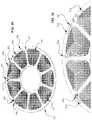
- FIGS. 1-3depict various views of an embodiment of a device 31 comprising an axial field rotary energy device (AFRED).
- device 31can comprise a motor that converts electrical energy to mechanical power, or a generator that converts mechanical power to electrical energy.
- Embodiments of device 31can include at least one rotor 33 comprising an axis 35 of rotation and a magnet (i.e., at least one magnet 37 ).
- a plurality of magnets 37are shown in the embodiment of FIG. 3 .
- Each magnet 37can include at least one magnet pole.
- Device 31also can include a stator 41 that is coaxial with the rotor 33 .
- Rotor 33can be coupled on a shaft 43 and with other hardware, such as one or more of the following items: a mount plate, fastener, washer, bearing, spacer or alignment element.
- Embodiments of the stator 41can include a single unitary panel, such as the printed circuit board (PCB) 45 shown in FIG. 4 .
- PCB 45can include at least one PCB layer 47 .
- certain embodiments described hereininclude twelve PCB layers 47 .
- PCB layers 47can be parallel and spaced apart in the axial direction.
- Each PCB layer 47can include at least one conductive trace 49 .
- Each trace 49is a separate conductive feature formed on a given PCB layer 47 .
- eight traces 49are shown in FIG. 4 . Traces 49 can be configured in a desired pattern, such as the coils illustrated in FIG. 4 .
- FIG. 4depicts an embodiment of one PCB layer 47 within a twelve-layer PCB 45 .
- the other eleven PCB layersare similar, with differences described below in regards to subsequent figures.
- each trace 49(forming a single coil) includes a first terminal 51 at the outer edge of the coil, and a second terminal 53 in the center of coil. Traces 49 are connected to other traces 49 using vias 55 .
- a first set of vias 55is disposed adjacent to the first terminal 51 at the outer edge of each coil, and a second set of vias 55 is disposed adjacent to the second terminal in the center of each coil.
- traces 49 on the illustrated PCB layer 47are not directly connected to an adjacent trace 49 on this illustrated PCB layer 47 , but rather are each directly connected to a corresponding trace 49 on another PCB layer 47 , as more thoroughly explained in regards to FIG. 5 and FIGS. 6A-6D .
- each trace 49is continuous and uninterrupted from its first terminal 51 to its second terminal 53 , and connections to such trace 49 are made only to the first and second terminals 51 , 53 .
- Each trace 49includes no other terminals for electrical connections.
- each trace 49can be seamlessly continuous with no other electrical connections, including no additional vias 55 , between the first and second terminals 51 , 53 .
- the width of a given trace 49can be not uniform. For example width 171 corresponding to an outer trace corner can be wider than width 173 corresponding to an inner trace corner.
- Gap 175 between adjacent concentric trace portions forming a single coilcan be the same or different than the gap 177 between adjacent traces (i.e., separate coils).
- a given tracecan comprise an outer width that is adjacent an outer diameter of the PCB and in a plane that is perpendicular to the axis 35 , and an inner width that is adjacent an inner diameter of the PCB and in the plane.
- the outer widthcan be greater than the inner width.
- a given tracecan comprise inner and outer opposing edges that are not parallel to each other.
- FIG. 5depicts an embodiment of a twelve-layer PCB 45 incorporating the PCB layer 47 shown in FIG. 4 .
- Each of the twelve PCB layers 47are closely spaced and form a “sandwich” of PCB layers 47 , labeled as 47 . 1 - 12 .
- a first trace 49 . 11(also described herein as “coil 49 . 11 ”) is shown whose first terminal 51 . 1 is coupled to an external terminal 61 for the device 31 .
- a trace 49 . 128is shown whose first terminal 51 . 12 is coupled to an external terminal 63 for the device 31 .
- traces 49there are eight traces 49 (coils) on each of twelve PCB layers 47 . 1 - 12 . These traces are coupled together (as more fully described below) such that current flowing into the external terminal 61 will flow through the ninety-six coils, then flow out the external terminal 63 (or conversely flow into external terminal 63 and out external terminal 61 ).
- only one trace 49e.g., coil 49 . 11
- only one trace 49e.g., coil 49 . 128
- each PCB layerincludes a plurality of coils that are co-planar and angularly and symmetrically spaced apart from each other about the axis, and the coils in adjacent PCB layers, relative to the axis, are circumferentially aligned with each other relative to the axis to define symmetric stacks of coils in the axial direction.
- FIG. 6Ais an exploded view of a portion of the twelve-layer PCB 45 shown in FIG. 5 , which is labeled to better illustrate how the coils are coupled together by vias 55 , 59 , and thus to better illustrate how current flows into the external terminal 61 , through the ninety-six coils, then flows out the external terminal 63 .
- input current 81 . 1flows into external terminal 61 .
- This currentflows “spirally” around coil 49 . 11 (on PCB layer 47 . 1 ) as current 81 . 2 and 81 . 3 , and reaches the second terminal 53 of coil 49 . 11 .
- a via 55 . 1couples the second terminal 53 of coil 49 .
- the currentflows through via 55 . 1 as current 81 . 4 , then flows spirally around coil 49 . 21 as current 81 . 5 until it reaches the first terminal 51 for coil 49 . 21 .
- a via 55 . 2couples the first terminal 51 of coil 49 . 21 to the first terminal of coil 49 . 12 on PCB layer 47 . 1 , which is adjacent to the first coil 49 . 11 .
- the traces 49 on the first PCB layer 47 . 1are generally reversed (mirror-imaged) relative to those on the second PCB layer 47 . 2 , so that the via 55 .
- the currentflows through coils 49 . 12 and 49 . 22 similarly to that described for coils 49 . 11 and 49 . 21 .
- the currentflows around coil 49 . 21 (on PCB layer 47 . 1 ) as current 82 . 2 and 82 . 3 to the second terminal 53 of coil 49 . 21 , flows through via 55 . 3 as current 82 . 4 to the second terminal 53 of coil 49 . 22 , then flows as current 82 . 5 and 82 . 6 around coil 49 . 22 until it reaches the first terminal 51 for coil 49 . 22 .
- a via 55 . 4couples the first terminal 51 of coil 49 . 22 to the first terminal 51 of coil 49 . 13 on PCB layer 47 .
- the vias 55 between the third and fourth PCB layers 47 . 3 , 47 . 4are configured identically as those between the first and second PCB layers 47 . 1 , 47 . 2 described above, and thus the via configuration and the corresponding current flow need not be repeated. This continues downward through the PCB layer “sandwich” until reaching the lowermost PCB layer 47 . 12 (not shown here). As described above, the first terminal 51 for trace (coil) 49 . 128 is coupled to the external terminal 63 . Consequently, the current that flows inward through external terminal 61 , after flowing through all ninety-six coils, flows outward through external terminal 63 .
- FIG. 6Bis an enlarged view of a group of vias 55 shown in FIG. 5 .
- This via groupis adjacent to the respective second terminal 53 for each of a group of vertically aligned coils 49 . 1 - 12 on each of the twelve PCB layers 47 . 1 - 12 .
- the traces 49 on the second PCB layer 47 . 2are generally reversed (mirror-imaged) relative to those on the first PCB layer 47 . 1 , so that the via 55 overlaps with both “tabs” on the respective second terminal 53 of these vertically adjacent coils.
- the second terminal 53 . 18includes a tab extending to the side of the trace.
- the second terminal 53 . 28includes a tab extending in the opposite direction to the side of the trace, so that these two tabs overlap.
- a via 55couples together these two overlapping tabs.
- each of five additional vias 55respectively couples overlapping terminals 53 . 38 and 53 . 48 , overlapping terminals 53 . 58 and 53 . 68 , overlapping terminals 53 . 78 and 53 . 88 , overlapping terminals 53 . 98 and 53 . 108 , and overlapping terminals 53 . 118 and 53 . 128 .
- FIG. 6Cshows two of these vias 55 in an exploded format.
- Terminal 53 . 38 of coil 49 . 38overlaps with terminal 53 . 48 of coil 49 . 48 , and are coupled together by a first via 55 .
- Terminal 53 . 58 of coil 49 . 58overlaps with terminal 53 . 68 of coil 49 . 68 , and are coupled together by a second via 55 .
- these pairs of overlapping tabs, together with their corresponding vias 55are staggered in a radial direction so that such vias 55 can be implemented using plated through-hole vias.
- such vias 55can be implemented as buried vias, in which case the vias need not be staggered, but rather can be vertically aligned.
- FIG. 6Dis an enlarged view of a group of vias 59 also shown in FIG. 5 .
- these vias 59are disposed in the gap between one specific adjacent pair of vertically aligned coils 49 (e.g., between uppermost layer coil 49 . 11 and 49 . 18 ), whereas vias 55 are disposed in the other gaps between other adjacent pairs of vertically aligned coils 49 .
- the vias 59are shown as plated through-hole vias. Vias 55 , 59 overlap with both “tabs” on the respective first terminal 51 of the corresponding coils.
- Vias 55couple horizontally adjacent coils on vertically adjacent layers, while vias 59 couple horizontally aligned coils on vertically adjacent layers, both as shown in FIG. 6A .
- the innermost via 59 . 5couples a respective coil on PCB layer 47 . 10 to a respective coil on PCB layer 47 . 11 .
- each trace 49can be electrically coupled to another trace 49 with at least one via 55 .
- each PCB layer 47has eight traces 49 and only one via 55 between traces 49 .
- every trace 49is electrically coupled to another trace 49 .
- two traces 49define a trace pair 57 .
- FIG. 7there are twelve PCB layers 47 . 1 - 12 , and there are six trace pairs 57 . 1 - 6 .
- Each trace pair 57can be electrically coupled to another trace pair 57 with at least one other via 59 (e.g., such as only one via 59 ).
- the traces 49 (e.g., coils) in each trace pair 57can be located on different PCB layers 47 , as shown in FIG. 6A . In other versions, however, the traces 49 in each trace pair 57 can be co-planar and located on the same PCB layer 47 .
- At least two of the traces 49are electrically coupled in series. In other versions, at least two of the traces 49 (e.g., coils) are electrically coupled in parallel. In still other versions, at least two of the traces 49 are electrically coupled in parallel, and at least two other traces 49 are electrically coupled in series.
- Embodiments of the device 31can include at least two of the trace pairs 57 electrically coupled in parallel. In other versions, at least two of the trace pairs 57 are electrically coupled in series. In still other versions, at least two of the trace pairs 57 are electrically coupled in parallel, and at least two other trace pairs 57 are electrically coupled in series.
- each PCB layer 47(only the top PCB layer 47 is shown in the top views) comprises a PCB layer surface area (LSA) that is the total surface area (TSA) of the entire (top) surface of the PCB 45 .
- the TSAdoes not include the holes in the PCB 45 , such as the center hole and the mounting holes that are illustrated.
- the one or more traces 49 (eight coils shown in FIG. 4 ) on the PCB layer 47can comprise a coils surface area (CSA).
- the CSAincludes the entire footprints of the coils (i.e., within their perimeters), not just their “copper surface area”.
- the CSAcan be in a range of at least about 50% of the PCB layer surface area, such as at least about 55%, at least about 60%, at least about 65%, at least about 70%, at least about 75%, at least about 80%, at least about 85%, at least about 90%, at least about 95%, at least about 97%, or even at least about 99% of the PCB layer surface area.
- the coils surface areacan be not greater than 99% of the PCB layer surface area, such as not greater than about 95%, not greater than about 90%, not greater than about 85%, not greater than about 80%, not greater than about 75%, or even not greater than about 70% of the PCB layer surface area.
- the coils surface areacan be in a range between any of these values.
- the CSAalso can be calculated with respect to any sensors or circuitry (such as IOT elements) on or in the PCB.
- IOT elementscan be limited to not greater than 50% of the TSA. Additionally, the IOT elements can be embedded within the CSA or embedded in at least part of the TSA this is not included in the CSA.
- each trace that forms a coili.e., including the conductive traces, but cannot necessarily include the spaces between the conductive traces
- the total area of each trace that forms a coilcan be viewed as a coil surface area. It is believed that performance of the device 31 is improved with increasing aggregate coil surface area, relative to the underlying PCB layer surface area on which the coil(s) is formed.
- the device 31can comprise a stator 41 comprising a single electrical phase. Versions of the stator 41 can consist of a single electrical phase.
- Each PCB layer 47can comprise a plurality of coils that are co-planar and symmetrically spaced apart about the axis 35 ( FIGS. 2 and 3 ). In one example, each coil consists of a single electrical phase.
- FIG. 8depicts an embodiment of the stator 41 comprising at least two electrical phases (e.g., three phases shown).
- Each PCB layer 47can include a plurality of coils (such as traces 49 ) as shown for each electrical phase.
- FIG. 8illustrates coils corresponding to three phases A, B and C.
- the coils for each electrical phase A, B, Ccan be angularly offset from each other with respect to the axis 35 ( FIGS. 2 and 3 ) within each PCB layer 47 to define a desired phase angle shift between the electrical phases A, B, C.
- there are nine traces 49 on each PCB layer 47since the embodiment of stator 41 in FIG.
- each trace 49 in phase Ais 120 electrical degrees apart from other traces 49 for phase A, and 40 electrical degrees apart from adjacent traces 49 for phases B and C.
- the traces 49 for phase B (relative to phases A and C) and for phase C (relative top phases A and B)are spaced likewise.
- each coile.g., trace 49
- the coilscan be configured to enable the stator 41 with two or more electrical phases (e.g., three phases shown in FIG. 8 ).
- FIG. 9is a simplified view of only some interior components of an embodiment of device 31 .
- Each of the magnets 37can include a magnet radial edge or element 67 (also referred to herein as a “magnet radial edge 67 ”), and each of the traces 49 can include a trace radial edge or element 69 (also referred to herein as a “coil radial edge 69 ”).
- the magnets 37are part of the rotor 33 ( FIG. 2 ) and rotate about the axis 35 with respect to the stationary stator 41 .
- At least portions of the radial elements 67 , 69can be skewed (i.e., not parallel) relative to each other.
- the magnet radial edges and coil radial edgesare not parallel and are angularly skewed relative to each other.
- the radial elements 67 , 69can be leading radial edges or trailing radial edges of the magnets 37 and traces 49 .
- the magnet and trace radial edges or elements 67 , 69can be linear as shown, and no portions of the magnet and trace radial elements 67 , 69 are parallel when the magnets 37 and traces 49 rotationally align in the axial direction.
- the magnet radial elements 67can be angularly skewed relative to the trace radial elements 69 , and the angular skew can be greater than 0 degrees, such as greater than 0.1 degrees, at least about 1 degree, at least about 2 degrees, at least about 3 degrees, at least about 4 degrees, or even at least about 5 degrees.
- the angular skewcan be not greater than about 90 degrees, such as not greater than about 60 degrees, not greater than about 45 degrees, not greater than about 30 degrees, not greater than about 25 degrees, not greater than about 15 degrees, not greater than about 10 degrees, or even not greater than about 5 degrees.
- the angular skewcan be in a range between any of these values.
- At least portions of the radial elements 67 , 69can be parallel to each other during rotational alignment.
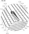
- FIGS. 10-12depict a simplified version of a device 131 with only some elements shown for ease of understanding.
- Device 131can include a stator 141 that is coaxial with a rotor 133 .
- each rotor 133can include one or more slits or slots 136 ( FIG. 10 ) that extend therethrough.
- the slots 136are angled with respect to axis 135 ( FIG. 12 ) and, thus, are not merely vertical.
- the angles of the slots 136can be provided at constant slopes, and can facilitate a cooling air flow within the device 131 . Slots 136 can enable air flow to be pulled or pushed through and/or around the rotors 133 and effectively cool the stators 141 . Additional slots can be provided in rotor spacers, such as rotor spacer 143 ( FIG. 12 ), particularly in embodiments having a plurality of stator segments, and particularly in embodiments having an inner diameter R-INT of the stator assembly ( FIG. 14 ) irrespective of the outer diameter R-EXT.
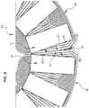
- the stator 141can include a plurality of stator segments 142 , each of which can be a separate PCB 145 .
- the stator segments 142can be coupled together, such as mechanically and electrically coupled together.
- Each stator segment 142can include a printed circuit board (PCB) having one or more PCB layers 147 ( FIG. 13 ) as described elsewhere herein.
- PCBprinted circuit board
- each PCB 145can have an even number of PCB layers 147 .
- the PCB 145can have an odd number of PCB layers 147 .
- Embodiments of the stator segments 142can comprise or correspond to only one electrical phase. Moreover, the stator 141 of device 131 can consist of or correspond to only one electrical phase. In other versions, the stator 141 can comprise or correspond to a plurality of electrical phases. As shown in FIG. 13 , each stator segment 142 includes at least one PCB layer 147 having at least one conductive trace 149 , such as the coil illustrated. In some versions ( FIG. 14 ), each stator segment 142 can have at least one PCB layer 147 having a plurality of traces 149 (e.g., coils) that are co-planar and angularly spaced apart from each other relative to the axis 135 ( FIGS. 11 and 12 ).
- traces 149e.g., coils
- each trace 149can comprise a single electrical phase.
- each stator segment 142can include a plurality of PCB layers 147 , each of which can be configured to correspond to only one electrical phase.
- each PCB layer 147 on each stator segment 142can include a plurality of axially co-planar traces 149 that are configured to correspond to only one electrical phase.
- each PCB layer 147can include at least one radial trace 150 that extends from about an inner diameter (ID) of the PCB 145 to about an outer diameter (OD) of the PCB 145 .
- each PCB layer 147can include a trace 149 that is continuous from an outermost trace portion 152 to a concentric innermost trace portion 154 .
- the traces 149can include radial traces 150 having linear sides and chamfered corners 156 .
- the linear sides of the radial tracescan be tapered, having an increasing trace width with increasing radial distance.
- Inner end turn traces 146 and outer end turn traces 148extend between the radial traces 150 to form a concentric coil.
- the taperscan improve the amount of conductive material (e.g., copper) that can be included in a PCB stator. Since many motors and generators comprise a round shape, the coils can be generally circular and, to fit together collectively on a stator, the perimeters of the coils can be somewhat pie-slice-shaped or triangular. In some versions, the coils can have a same width in a plane perpendicular to the axis, and in other versions the coils can be tapered to increase the conductor (e.g., copper) densities of the coils. Improving copper density can have significant value to reduce electrical resistance, I 2 R losses and heat generation, and increase the ability to carry a higher electrical current to provide a machine with higher efficiency.
- conductive materiale.g., copper
- each PCB layer 147can include only linear traces 149 ( FIGS. 15-17 ).
- Linear traces 149can be continuous from an outermost trace 152 to a concentric innermost trace 154 .
- no trace 149 of the PCB layers 147is non-linear.
- embodiments of the only linear traces 149can include turns, such as, for example, rounded corners or chamfered corners.
- a “turn”includes a trace portion connecting a radial trace to an end turn trace.
- the PCB layer 147can include one or more non-linear, such as curvilinear traces.
- the PCB 145can include a plurality of PCB layers 147 that are spaced apart from each other in the axial direction.
- the PCB layers 147can comprise layer pairs 157 ( FIG. 17 ; see pairs 157 . 1 to 157 . 4 ).
- Each layer pair 157can be defined as two PCB layers that are electrically coupled together.
- at least one of the PCB layers 147is electrically coupled to another PCB layer 147 in series or in parallel.
- at least one layer pair 157is electrically coupled to another layer pair 157 in series or in parallel.
- at least one of the layer pairs 157comprises two PCB layers 147 . 6 and 147 . 7 that are axially adjacent to each other.
- At least one of the layer pairs 157comprises two PCB layers 147 . 1 and 147 . 3 that are not axially adjacent to each other.
- at least one of the layer pairs 157can be axially adjacent to the layer pair 157 to which said at least one of the layer pairs is electrically coupled.
- at least one of the layer pairs 157can be not axially adjacent to the layer pair 157 to which said at least one of the layer pairs 157 is electrically coupled.
- Embodiments of the PCB layers 147can include at least one layer set 181 ( FIG. 17 ).
- layer set 181can include a first layer 147 . 1 , a second layer 147 . 2 , a third layer 147 . 3 and a fourth layer 147 . 4 .
- a first via 159can couple the first layer 147 . 1 to the third layer 147 . 3
- a second via 155can couple the third layer 147 . 3 to the second layer 147 . 2
- a third via 159can couple the second layer 147 . 2 to the fourth layer 147 . 4 .
- the first, second and third vias 159 , 155 , 159are the only vias that intra-couple the layer set 181 .
- the two, directly axially adjacent PCB layers 147 . 1 and 147 . 2are not directly electrically coupled to each other.
- each of the vias 159couples a pair of non-adjacent PCB layers 147 while bypassing (i.e., making no contact to) the intervening PCB layer 147 .
- via 159 . 1couples PCB layer 147 . 1 to PCB layer 147 . 3 , and makes no contact with PCB layer 147 . 2 .
- each of the vias 155couples a pair of adjacent PCB layers 147 .
- via 155 . 2couples PCB layer 147 . 2 to PCB layer 147 . 3 .
- layer pair 157 . 1includes PCB layer 147 . 1 and PCB layer 147 . 3 .
- Layer pair 157 . 2includes PCB layer 147 . 2 and PCB layer 147 . 3 .
- Layer pair 157 . 3includes PCB layer 147 . 2 and PCB layer 147 . 4 .
- Layer pair 157 . 4includes PCB layer 147 . 4 and PCB layer 147 .
- Layer pair 157 . 5includes PCB layer 147 . 5 and PCB layer 147 . 7 .
- Layer pair 157 . 6includes PCB layer 147 . 6 and PCB layer 147 . 7 .
- Layer pair 157 . 7includes PCB layer 147 . 6 and PCB layer 147 . 8 .
- each viais shown having a blunt end and a pointed end. This shape is not intended to imply any structural difference between the two ends of each via, but rather is intended to provide a consistent indication of the direction of current flow through each via.
- each viais also shown as extending vertically only as far as necessary to couple the corresponding pair of PCB layers 147
- each viacan be implemented as a plated through-hole via extending through the entire PCB (e.g., see vias 59 in FIG. 6D ).
- Each of such plated through-hole viascan make contact with any PCB layer 147 having a trace 149 that overlaps such a via.
- FIG. 17each via is shown having a blunt end and a pointed end. This shape is not intended to imply any structural difference between the two ends of each via, but rather is intended to provide a consistent indication of the direction of current flow through each via.
- each viais also shown as extending vertically only as far as necessary to couple the corresponding pair of PCB layers 147
- each viacan be
- a given through-hole viaoverlaps and makes a connection with only two PCB layers 147 , while the traces 149 of all remaining PCB layers 147 do not overlap the given via and are not connected to the given via.
- some embodimentscan include buried vias that vertically extend only between the corresponding PCB layers 147 to be connected.
- FIGS. 18, 19, 20A-20Hdisclose embodiments of a module 201 for one or more axial field rotary energy devices 231 .
- Device(s) 231can comprise any of the axial field rotary energy device embodiments disclosed herein.
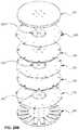
- the module 201includes a housing 203 having a side wall 211 , three stators (shown as PCB stator panel 245 ), and four rotor assemblies 242 , 244 .
- Each rotor assembly 244is vertically disposed between two stators 245 , and includes a pair of identical rotor panels 236 and a group of rotor permanent magnets 237 .
- Each rotor panel 236includes a set of recessed indentations to position each of the rotor magnets 237 , and the two rotor panels 236 are secured together to sandwich each of the group of rotor magnets between the opposing upper and lower rotor panels 236 .
- Each rotor assembly 242is vertically disposed between a stator 245 and a housing 203 , and includes a torque plate 233 , a rotor panel 234 , and a group of rotor permanent magnets 237 .
- the vertical spacing between rotor assembliesis maintained by spacers (e.g., 262 , 263 ) that extend from one rotor assembly to the adjacent rotor assembly through a hole in the intervening stator panel 245 .
- the rotor spacingcorresponds to the thickness of the stator panel 245 and the desired air gap spacing (such as above and/or below) the stator panel 245 .
- Each rotor spacercan define the air gap between the rotor assembly and the stator (and also can define the height 215 of the side wall slots, as noted below).
- Each rotor spaceris positioned between two rotor assemblies.
- rotor spacer 262is positioned between the uppermost rotor assembly 242 and the adjacent inner rotor assembly 244 (and likewise for the lowermost rotor assembly 242 ).
- Each rotor spacer 263is positioned between adjacent inner rotor assemblies 244 .
- such rotor spacer 263can have a different thickness as rotor spacer 262 , due to mechanical differences in the uppermost and lowermost rotor assemblies 242 relative to the inner rotor assemblies 244 , to define the same air gap spacing between all rotors and stators.
- the use of the rotor spacers 262 , 263enables stacking multiple rotors (e.g., rotor assemblies 242 , 244 ), which can provide significant flexibility in the configuration of module 201 .
- Embodiments of the housing 203can include a side wall 211 ( FIGS. 20A-20H and 21 ).
- Side wall 211can be configured to orient the stator (e.g., stator panel 245 ) at a desired angular orientation with respect to the axis 235 .
- the side wall 211can comprise a plurality of side wall segments 212 .
- the side wall segments 212can be configured to angularly offset the plurality of stators 245 at desired electric phase angles (see, e.g., FIGS. 20C and 25 ) for the module 201 , relative to the axis.
- the side wall 211can include a radial inner surface having one or more slots 214 formed therein.
- Each slot 214can be configured to receive and hold the outer edge of the stator 245 to maintain the desired angular orientation of the stator 245 with respect to the axis 235 .
- each side wall 211includes three slots 214 formed between mating pairs of side wall segments 212 .
- the upper and lower sidewall segments 212 of such mating pairare identical and thus can be used interchangeably, but in other contemplated embodiments the upper and lower side wall segments 212 can be different due to asymmetrical slots 214 , differences in mounting hole placement, or some other aspect.
- the slots 214can be configured to axially, such as vertically, position the outer edge of each stator 245 at prescribed axial positions with respect to other stators 41 . Since the rotor spacers 262 , 263 determine the axial spacing between each stator 245 (at the innermost extent thereof) and the corresponding rotor assembly (e.g., 242 , 244 in FIGS.
- each side wall segment 212can be configured to provide one side wall slot 214 .
- the group of side wall segments 212together provide numerous slots 214 (e.g., eight such slots 214 ) radially spaced around the module 201 .
- Collectively such side wall slots 214can be viewed as facilitating the air gap spacing between the stator and the adjacent rotor.
- Versions of the module 201can include a housing 203 having mechanical features (e.g., keyed shafts 209 in FIG. 21 ) configured to mechanically couple the housing 203 to a second housing 203 of a second module 201 .
- housing 203can be configured with electrical elements (e.g., electrical connector couplings 204 in FIGS. 21 and 22 ) to electrically couple the housing 203 to the second housing 203 .
- the module 201is air cooled and is not liquid cooled. In other versions, liquid-cooled embodiments can be employed.
- the module 201can be configured to be indirectly coupled to the second module 201 with an intervening structure, such as a frame 205 ( FIGS. 21-22 ).
- the module 201can be configured to be directly coupled to the frame 205 , such that the module 201 is configured to be indirectly coupled to the second module 201 with other components depending on the application.
- the module 201can be configured to be directly coupled to the second module 201 without a frame, chassis or other intervening structure.
- At least one rotor 233 , at least one magnet 237 and at least one stator 241 having at least one PCB 245 with at least one PCB layer 147 having at least one trace 149can be located inside and surrounded by the housing 203 .
- each module 201consists of a single electrical phase. In other versions each module 201 comprises a plurality of electrical phases. Examples of each module 201 can include a plurality of PCB panels 245 ( FIGS. 20A-20H ). Each PCB panel 245 can comprise a single electrical phase or a plurality of electrical phases. The PCB panels can be unitary panels or can comprise stator segments as described elsewhere herein.
- the module 201 and the second module 201can be configured to be identical to each other. In another version, the module 201 and the second module 201 can differ.
- the module 201can differ from the second module 201 by at least one of the following variables: power input or output, number of rotors 233 , number of magnets 237 , number of stators 41 (see previous drawings), number of PCBs 245 , number of PCB layers 47 (see previous drawings), number of traces 49 (see previous drawings), and angular orientation with respect to the axis 235 .
- one or more of these variablescan be modified to achieve differences in power efficiency, torque, achievable revolutions per minute (RPM), so that different modules 201 can be utilized to better tailor operation as a function of the load or other desired operating parameter.
- RPMrevolutions per minute
- the module 201can include at least one latch 207 ( FIGS. 23 and 24 ) configured to mechanically secure the modules together.
- FIG. 23depicts modules nested together with the latches 207 open
- FIG. 24depicts modules nested together with the latches 207 closed.
- the latches 207can be symmetrically arrayed with respect to the axis 235 .
- a top module(not shown) can be configured to be axially on top of another module, and the top module can differ structurally from the second module.
- the top module 201can include latches 207 only on its bottom side, and omit such latches 207 on its top side.
- the shaft 209can extend from the bottom module 201 , but not from the top module 201 .
- the module 201can include a keyed shaft 209 .
- Module 201can be mounted to the keyed shaft which can be configured to mechanically couple to another module 201 .
- Some embodimentscan further comprise a body 213 ( FIG. 26 ) (also referred to herein as an “enclosure”).
- Body 213can be configured to contain and coaxially mount a plurality of the modules 201 within the body 213 .
- the body 213comprises two halves that are coupled together with fasteners.
- each module 201comprises a single electrical phase
- the body 213can be configured to maintain the modules 201 at a desired electrical phase angle with respect to the axis 235 .
- the body 213comprises a plurality of electrical phases
- the body 213can be configured to maintain the modules 201 at desired electrical phase angles with respect to the axis 235 .
- each body 213can include mechanical features such as coupling structures configured to mechanically couple each body 213 to at least one other body 213 , and electrical elements configured to electrically couple each body 213 to at least one other body 213 .
- Each body 213can be configured to directly or indirectly couple to at least one other body 213 .
- a body(or more than one intercoupled bodies) can include a number of electrical phases (such as about 4 to 99; e.g., at least 10, 11, 12, 13, 14, 15 or more) electrical phases of alternating current output.
- the AC current outputcan act like a DC-like output ripple without being rectified or requiring a power conversion. In other versions, such AC current output can be rectified.
- Embodiments of a system for providing energyalso are disclosed.
- the systemcan include a plurality of modules 201 comprising axial field rotary energy devices.
- the modules 201can be interchangeably connectable to each other to configure the system for a desired power output.
- Each modulecan be configured based on any of the embodiments described herein.
- the systemcan comprise a generator or a motor.
- Embodiments of the systemcan include at least two of the modules 201 configured to differ.
- the modules 201can differ from each other by at least one of the following variables: power output or input, number of rotors, number of magnets, number of stators, number of PCBs, number of PCB layers, number of coils, and angular orientation with respect to the axis.
- Embodiments of a method of repairing an axial field rotary energy deviceare disclosed as well.
- the methodcan include the following steps: providing a body 213 having a plurality of modules 201 .
- Each module 201can be configured as described for any of the embodiments disclosed herein.
- the methodalso can include mechanically and electrically coupling the modules 201 such that the modules 201 are coaxial; operating the axial field energy device; detecting a problem with one of the modules 201 and stopping operation of the axial field energy device; opening the body 213 and de-attaching the problem module 201 from all other modules 201 to which the problem module 201 is attached; installing a replacement module 201 in the body 213 in place of the problem module 201 and attaching the replacement module 201 to the other modules 201 to which the problem module 201 was attached; and then re-operating the axial field energy device.
- the methodinclude angularly aligning the modules to at least one desired electrical phase angle with respect to the axis.
- the methodcan include providing a plurality of bodies 213 , and mechanically and electrically coupling the bodies 213 .
- Still other embodiments of a method of operating an axial field rotary energy devicecan include providing an enclosure having a plurality of modules, each module comprises a housing, rotors rotatably mounted to the housing, each rotor comprises an axis and a magnet, stators mounted to the housing coaxially with the rotors, each stator comprises a printed circuit board (PCB) having a coil, each stator consists of a single electrical phase, and selected ones of the stators are set at desired phase angles with respect to the axis; mechanically and electrically coupling the modules such that the modules are coaxial within the enclosure; and then operating the axial field energy device.
- PCBprinted circuit board
- the enclosure and each modulecan comprise a single electrical phase
- the methodcan comprise angularly aligning the modules at a desired electrical phase angle with respect to the axis.
- the methodcan include the enclosure with a plurality of electrical phases, each module comprises a single electrical phase, and angularly orienting the modules at desired electrical phase angles with respect to the axis.
- the enclosure and each modulecan include a plurality of electrical phases, and angularly misaligning the modules at desired electrical phase angles with respect to the axis.
- Some versions of the methodcan include providing a plurality of bodies, and the method further comprises mechanically and electrically coupling the bodies to form an integrated system.
- Each modulecan include a plurality of stators that are angularly offset from each other with respect to the axis at desired electrical phase angles.
- each statorconsists of only one PCB.
- each statorcomprises two or more PCBs that are coupled together to form each stator.
- the enclosurecan have a number electrical phases of alternating current (AC) output that is substantially equivalent to a clean direct current (DC)-like ripple without a power conversion, as described herein.
- ACalternating current
- DCdirect current
- a method of repairing an axial field rotary energy devicecan include providing a plurality of bodies that are coupled together, each enclosure having a plurality of modules, each module comprising a housing, a rotor rotatably mounted to the housing, the rotor comprises an axis and a magnet, a stator mounted to the housing coaxially with the rotor, and the stator comprises a printed circuit board (PCB); mechanically and electrically coupling the modules; operating the axial field rotary energy device; detecting an issue with a first module in a first enclosure and stopping operation of the axial field rotary energy device; opening the first enclosure and disassembling the first module from the first enclosure and any other module to which the first module is attached; installing a second module in the first enclosure in place of the first module and attaching the second module to said any other module to which the first module was attached; and then re-operating the axial field rotary energy device.
- PCBprinted circuit board
- Embodiments of each modulecan have only one orientation within the enclosure, such that each module can be installed or uninstalled relative to the enclosure in singular manners.
- the purpose of such designsis so the person doing work on the system cannot re-install new modules into an existing system the wrong position. It can only be done in only one orientation.
- the methodcan occur while operation of the AFRED is suspended, and treatment of the first module occurs without interrupting said any other module, and without modifying or impacting said any other module.
- FIG. 27depicts another embodiment of a PCB stator 311 for an axial field rotary energy device, such as those disclosed herein.
- PCB stator 311comprises a substrate having one or more traces 313 that are electrically conductive.
- PCB stator 311comprises eight coils of traces 313 .
- PCB stator 311can comprise more than one layer of traces 313 .
- the traces 313 on each layerare co-planar with the layer.
- the traces 313are arrayed about a central axis 315 of the PCB stator.
- FIG. 28is an enlarged top view of a portion of the PCB stator of FIG. 27 .
- each trace 313comprises radial portions 317 (relative to axis 315 ) and end turns 319 extending between the radial portions 317 .
- Each trace 313can be split with a slit 321 .
- only radial portions 317comprise slits 321 .
- Slits 321can help reduce eddy current losses during operation. Eddy currents oppose the magnetic field during operation. Reducing eddy currents increases magnetic strength and increases efficiency of the system.
- wide tracescan allow eddy currents to build.
- the slits in the traces 313can reduce the opportunity for eddy currents to form.
- the slitscan force the current to flow through the traces 313 more effectively.
- the axial field rotary energy devicecan comprise a “smart machine” that includes one or more sensors integrated therewith.
- a sensorcan be configured to monitor, detect, or generate data regarding operation of the axial field rotary energy device.
- the operational datacan include at least one of power, temperature, rate of rotation, rotor position, or vibration data.
- Versions of the axial field rotary energy devicecan comprise an integrated machine that includes one or more control circuits integrated therewith.
- Other versions of the axial field rotary energy devicecan comprise a fully integrated machine that includes one or more sensors and one or more control circuits integrated therewith.
- one or more sensors and/or control circuitscan be integrated with the PCB and/or integrated with the housing.
- these control circuitscan be used to drive or propel the machine.
- such a control circuitcan include an input coupled to receive an external power source, and can also include an output coupled to provide a current flowing through one or more stator coils.
- the control circuitis configured to supply torque and/or torque commands to the machine.
- such a control circuitcan include an input coupled to receive the current flowing through the coil, and can also include an output coupled to generate an external power source.
- FIG. 29shows another exemplary stator 340 having integrated sensors (e.g., 342 , 346 ) that are attached to its uppermost PCB layer 47 .
- One such sensor 342is coupled to a secondary coil 344 that can be used to transmit/receive data to/from an external device, and can be also used to couple power to the sensor 342 .
- the secondary coilcan be configured to utilize magnetic flux developed during operation to provide power for the sensor 342 .
- the secondary coilcan be configured to receive inductively coupled power from an external coil (not shown).
- the secondary coil 344may also be referred to herein as a micro-coil, or a miniature coil, as in certain embodiments such a secondary coil can be much smaller than a stator coil 49 , but no relative size inference is intended. Rather, such a secondary coil 344 is distinct from the stator coils 49 that cooperate with the rotor magnets, as described above.
- a secondary coil integrated with the PCB stator 311can, in certain embodiments, be disposed on the PCB stator 311 (e.g., fabricated on, or attached to, its uppermost PCB layer 47 ).
- Such a secondary coil integrated with the PCB stator 311can, in certain embodiments, be disposed within (i.e., embedded within) the PCB stator 311 .
- the secondary coil 344provides power to a sensor connected thereto. Such coupled power can be primary or auxiliary power for the sensor.
- Sensor 346is coupled to the first terminal 51 for one of the traces 49 on the upper PCB layer 47 , and can sense an operating parameter such as voltage, temperature at that location, and can also be powered by the attached coil (e.g., one of the coils 49 ).
- Sensor 348is coupled to an external terminal 350 , and likewise can sense an operating parameter such as voltage, temperature at that location, and can also be powered by the voltage coupled to the external terminal 350 .
- Sensor 350is disposed at an outer edge of the PCB stator 340 , but is coupled to no conductor on the PCB layer 47 .
- such a sensorcan be embedded directly in one of the coils 49 and can be electrically powered directly by the coil 49 .
- such a sensorcan be powered and connected to the coil 49 through a separate connection that is disposed on or within the PCB layer 47 , such as the connection between the first terminal 51 and sensor 346 .
- a connectioncan be disposed on the PCB layer 47 or disposed within the PCB (e.g., on an internal layer of the PCB).
- the sensor and/or circuitrycan get power from an external power source.
- one type of external power sourcecan be a conventional wall electrical socket which can be coupled to the housing of the motor or generator.
- the sensorscan provide operators of generator or motor products with real time operational data as well as, in certain embodiments, predictive data on various parameters of the product. This can include how the equipment is operating, and how and when to schedule maintenance. Such information can reduce product downtime and increase product life.
- the sensorcan be integrated within the housing.
- the sensorscan be embedded within the PCB stator 340 , as is shown in FIG. 30 (e.g., sensors 362 , 366 , 368 , 372 , and coil 364 ).
- Hall effect sensorsare used for proximity switching, positioning, speed detection, and current sensing applications.
- the Hall effect sensoroperates as an analog transducer, directly returning a voltage.
- a sensoris an optical sensor.
- Optical sensorscan measure the intensity of electromagnetic waves in a wavelength range between UV light and near infrared light.
- the basic measurement deviceis a photodiode. Combining a photodiode with electronics makes a pixel.
- the optical sensorcan include an optical encoder that uses optics to measure or detect the positions of the magnetic rotor.
- thermocouple sensorto measure temperature.
- Thermocouplescomprise two wire legs made from different metals. The wires legs are welded together at one end, creating a junction. The junction is where the temperature is measured. When the junction experiences a change in temperature, a voltage is created.
- Accelerometersare an electromechanical device used to measure acceleration forces. Such forces can be static, like the continuous force of gravity or, as is the case with many mobile devices, dynamic to sense movement or vibrations. Acceleration is the measurement of the change in velocity, or speed divided by time.
- a gyro sensorwhich functions like a gyroscope, also can be employed in these systems.
- Gyro sensorscan be used to provide stability or maintain a reference direction in navigation systems, automatic pilots, and stabilizers.
- the PCB stator 340also can include a torque sensor.
- a torque sensor, torque transducer or torque meteris a device for measuring and recording the torque on a rotating system, such as the axial field rotary energy device.
- Vibration sensorscan measure, display and analyze linear velocity, displacement and proximity, or acceleration. Vibration, even minor vibration, can be a telltale sign of the condition of a machine.
- the sensors depicted in FIG. 29 and FIG. 30can also represent control circuits integrated with the PCB stator 345 .
- Such control circuitscan be disposed on a surface of the PCB (analogously to the sensors depicted in FIG. 29 ), disposed within (i.e., embedded within) the PCB (analogously to the sensors depicted in FIG. 30 ), and/or integrated with or within the housing (e.g., housing 203 in FIG. 18 ).
- the control circuitcan implement power conversion from an AC voltage developed in the stator coils to an external desired power source (e.g., an AC voltage having a different magnitude than the coils voltage, a DC voltage developed by rectifying the coils voltage).
- the control circuitcan implement an integrated drive circuitry that can provide desired AC current waveforms to the stator coils to drive the motor.
- the integrated drivecan be a variable frequency drive (VFD), and can be integrated with the same housing as the motor.
- VFDvariable frequency drive
- the sensors and/or circuitry disclosed hereincan be wirelessly or hard-wired to any element of, on or in the housing. Alternatively, the sensors and/or circuitry can be located remotely relative to the housing.
- Each of these sensors and control circuitscan include a wireless communication circuit configured to communicate with an external device through a wireless network environment.
- Such wireless communicationcan be unidirectional or bidirectional, and can be useful for monitoring a status of the system, operating the system, communicating predictive data, etc.
- the wireless communication via the networkcan be conducted using, for example, at least one of long term evolution (LTE), LTE-advanced (LTE-A), code division multiple access (CDMA), wideband CDMA (WCDMA), universal mobile telecommunication system (UMTS), wireless broadband (WiBro), or global system for mobile communications (GSM), as a cellular communication protocol.
- LTElong term evolution
- LTE-ALTE-advanced
- CDMAcode division multiple access
- WCDMAwideband CDMA
- UMTSuniversal mobile telecommunication system
- WiBrowireless broadband
- GSMglobal system for mobile communications
- the wireless communicationcan include, for example, short-range communication.
- the short-range communicationcan be conducted by, for example, at least one of wireless fidelity (WiFi), Bluetooth®, near field communication (NFC), or GNSS.
- GNSScan include, for example, at least one of global positioning system (GPS), Glonass® global navigation satellite system, Beidou® navigation satellite system, or Galileo®, the European global satellite-based navigation system.
- GPSglobal positioning system
- Beidou® navigation satellite systemBeidou® navigation satellite system
- Galileo®the European global satellite-based navigation system.
- the networkcan be a communication network, for example, at least one of a computer network (for example, local area network (LAN) or wide area network (WAN)), the Internet, or a telephone network.
- such a wireless communication circuitcan be coupled to a secondary coil (e.g., secondary coil 344 ) to communicate telemetry information, such as the operational data described above.
- a secondary coile.g., secondary coil 344
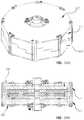
- FIGS. 31 and 32show an embodiment of an assembly for mechanically coupling together stator segments 380 to form a stator.
- a clasp 382slides over portions of a mounting pad 381 on two adjacent stator segments 380 , which is secured by a pair of nuts on each of two bolts (e.g., bolt 384 ).
- the clasp 382includes an alignment tab 392 that can be positioned into a side wall slot 214 as described above.
- the inner diameter edge of the two adjacent stator segments 380slides into a channeled rotor spacer 390 in the shape of an annular ring.
- this rotor spacer 390can ride on a thrust bearing with the rotor to allow the rotor spacer 390 and stator to remain stationary while the rotor rotates.
- a rotor spacer as described abovee.g., FIGS. 18, 20A-20H
- Circuit 386can connect to a trace on the upper layer (or another layer using a via) of the stator segment 380 .
- circuit 388can connect to a trace on any layer of the stator segment 381 .
- Such circuits 386 , 388can include any of the sensors described above ( FIGS. 29-30 ), but can also merely provide an electrical connection from the respective PCB to the wire 387 .
- electrical connectionalso can be made via the mounting surface of the PCB being a conductive material and connected to the coil and then coupling those components through the clasp, which also can include conductive material on the inner surface thereof.
- Electrical connectioncan also be implemented using the clasp 382 in combination with an electrically conductive mounting pad 383 . If the mounting pad 383 is continuous and unbroken, the clasps 382 can provide a common electrical connection around the circumference of the stator. If such mounting pads are discontinuous and broken into two pieces (as shown by the dash lines, with each piece coupled to a respective terminal of a trace on that segment, the clasps 382 can serially connect such stator segments.
- the axial field rotary energy deviceis suitable for many applications.
- the PCB stator 340can be configured for a desired power criteria and form factor for devices such as permanent magnet-type generators and motors. Such designs are lighter in weight, easier to produce, easier to maintain and more capable of higher efficiency.
- Examples of permanent magnet generator (PMG) applicationscan include a wind turbine generator, micro-generator application, permanent magnet direct drive generator, steam turbine generator, hydro generator, thermal generator, gas generator, wood-fire generator, coal generator, high frequency generator (e.g., frequency over 60 Hz), portable generator, auxiliary power unit, automobiles, alternator, regenerative braking device, PCB stator for regenerative braking device, back-up or standby power generation, PMG for back up or standby power generation, PMG for military usage and a PMG for aerospace usage.
- PMGpermanent magnet generator
- examples of a permanent magnet motorcan include an AC motor, DC motor, servo motor, stepper motor, drone motor, household appliance, fan motor, microwave oven, vacuum machine, automobile, drivetrain for electric vehicle, industrial machinery, production line motor, internet of things sensors (IOT) enabled, heating, ventilation and air conditioning (HVAC), HVAC fan motor, lab equipment, precision motors, military, motors for autonomous vehicles, aerospace and aircraft motors.
- IOTinternet of things sensors
- HVACheating, ventilation and air conditioning
- HVACheating, ventilation and air conditioning
- An axial field rotary energy devicecomprising:
- a rotorcomprising an axis of rotation and a magnet
- statorcoaxial with the rotor, the stator comprising a printed circuit board (PCB) having a plurality of PCB layers that are spaced apart in an axial direction, each PCB layer comprises a coil having only two terminals for electrical connections, each coil is continuous and uninterrupted between its only two terminals, each coil consists of a single electrical phase, and one of the two terminals of each coil is electrically coupled to another coil with a via to define a coil pair; and
- PCBprinted circuit board
- each coil pairis electrically coupled to another coil pair with another via.
- each PCB layercomprises a plurality of coils, and the coils in each coil pair are co-planar and located on a same PCB layer.
- each PCB layercomprises a PCB layer surface area
- the coil on each PCB layercomprises a plurality of coils having a coils surface area that is in a range of at least about 75% to about 99% of the PCB layer surface area.
- each PCB layercomprises a plurality of coils that are co-planar and symmetrically spaced apart about the axis, and the coils in adjacent PCB layers, relative to the axis, are circumferentially aligned with each other relative to the axis to define symmetric stacks of coils in the axial direction.
- statorcomprises at least two electrical phases.
- each PCB layercomprises a plurality of coils for each electrical phase, and the coils for each electrical phase are angularly offset from each other with respect to the axis within each PCB layer to define a desired phase angle shift between the electrical phases.
- statorcomprises a single unitary panel.
- each coilis coupled to another coil with only one via.
- each coil pairis coupled to another coil pair with only one via.
- An axial field rotary energy devicecomprising:
- a rotorcomprising an axis of rotation and a magnet
- statorcoaxial with the rotor, the stator comprising a printed circuit board (PCB) having a plurality of PCB layers that are spaced apart in an axial direction, each PCB layer comprises a coil, and the plurality of PCB layers comprise:
- the coils in each coil layer pairare on different PCB layers, at least two of the coil layer pairs are coupled together in parallel, and at least another two of the coil layer pairs are coupled together in series.
- statorcomprises at least two electrical phases.
- each PCB layercomprises a plurality of coils for each electrical phase, and the coils for each electrical phase are angularly offset from each other with respect to the axis within each PCB layer to define a desired phase angle shift between the electrical phases.
- each coilconsists of a single electrical phase.
- An axial field rotary energy devicecomprising:
- a rotorcomprising an axis of rotation and a magnet
- statorcoaxial with the rotor, the stator comprising a printed circuit board (PCB) having a first PCB layer and a second PCB layer that are spaced apart from each other in an axial direction, each PCB layer comprises a coil that is continuous, and each coil has only two terminals for electrical connections; and
- PCBprinted circuit board
- An axial field rotary energy devicecomprising:
- a rotorcomprising an axis of rotation and a magnet
- the statorcomprises a printed circuit board (PCB) consisting of a single unitary panel having at least two electrical phases, the PCB comprises a plurality of PCB layers that are spaced apart in an axial direction, each PCB layer comprises a plurality of coils, each coil has only two terminals for electrical connections, each coil is continuous and uninterrupted between its only two terminals, each coil consists of a single electrical phase, and one of the two terminals of each coil is electrically coupled to another coil with only one via to define a coil pair, each coil pair is electrically coupled to another coil pair with another only one via;
- PCBprinted circuit board
- the coils in each PCB layerare co-planar and symmetrically spaced apart about the axis, and the coils in adjacent PCB layers are circumferentially aligned with each other to define symmetric stacks of coils in the axial direction;
- each PCB layercomprises a plurality of coils for each electrical phase, and the coils for each electrical phase are angularly offset from each other with respect to the axis within each PCB layer to define a desired phase angle shift between the electrical phases.
- An axial field rotary energy devicecomprising:
- a rotorcomprising an axis of rotation and a magnet
- statorcoaxial with the rotor, the stator comprises a plurality of stator segments coupled together about the axis, each stator segment comprises a printed circuit board (PCB) having a PCB layer comprising a coil, and each stator segment comprises only one electrical phase.
- PCBprinted circuit board
- statorcomprises a plurality of electrical phases.
- each PCB layercomprises a plurality of coils that are co-planar and angularly spaced apart from each other relative to the axis.
- each stator segmentcomprises a plurality of PCB layers, each of which is configured to provide said only one electrical phase.
- each PCB layer on each stator segmentcomprises a plurality of coils that are co-planar and configured to provide said only one electrical phase.
- each coilcomprises radial traces that extend from about an inner diameter of the PCB to about an outer diameter of the PCB.
- each coilcomprises a trace that is continuous from an outermost trace portion to a concentric innermost trace portion, and the coils comprise radial elements having linear sides and turns.
- each coilcomprises only linear traces that are continuous from an outermost trace to a concentric innermost trace, no trace of the PCB layers is non-linear, and said each coil comprises corners to join the only linear traces.
- each PCB layercomprises a PCB layer surface area
- the coil on each PCB layercomprises a plurality of coils having a coils surface area that is in a range of at least about 75% to about 99% of the PCB layer surface area.
- each PCB layercomprises a plurality of coils that are co-planar and symmetrically spaced apart about the axis, and the coils in adjacent PCB layers are circumferentially aligned with each other relative to the axis to define symmetric stacks of coils in an axial direction.
- An axial field rotary energy devicecomprising:
- a rotorcomprising an axis of rotation and a magnet
- statorcoaxial with the rotor
- statorcomprises a plurality of stator segments coupled together about the axis
- each stator segmentcomprises a printed circuit board (PCB) having a plurality of PCB layers each comprising a coil
- the PCB layersare spaced apart from each other in an axial direction
- each of the PCBshas an even number of PCB layers
- the PCB layerscomprise layer pairs
- each layer pairis defined as two PCB layers that are electrically coupled together with a via
- each layer pairis coupled to another layer pair with another via.
- An axial field rotary energy devicecomprising:
- a rotorcomprising an axis of rotation and a magnet
- statorcoaxial with the rotor, the stator comprises a plurality of stator segments and a plurality of electrical phases, each stator segment comprises a printed circuit board (PCB) having at least one PCB layer with a coil, and each stator segment comprises only one electrical phase.
- PCBprinted circuit board
- An axial field rotary energy devicecomprising:
- a rotorcomprising an axis of rotation and a magnet
- statorcoaxial with the rotor, the stator comprises a plurality of stator segments coupled together about the axis, each stator segment comprises a printed circuit board (PCB) having a plurality of PCB layers each comprising coils, the PCB layers are spaced apart from each other in an axial direction, each of the PCBs has an even number of PCB layers, the PCB layers comprise layer pairs, and each layer pair is defined as two PCB layers that are electrically coupled together; and
- PCBprinted circuit board
- the coils in each PCB layerare co-planar and angularly and symmetrically spaced apart from each other about the axis, and the coils in adjacent PCB layers are circumferentially aligned with each other to define symmetric stacks of coils in the axial direction.
- each PCB layeris configured to provide only one electrical phase.
- a module for an axial field rotary energy devicecomprising:
- a housinghaving coupling structures configured to mechanically couple the housing to a second housing of a second module, and electrical elements configured to electrically couple the housing to the second housing;
- a rotorrotatably mounted to the housing, and the rotor comprises an axis and a magnet;
- statormounted to the housing coaxially with the rotor, and the stator comprises a printed circuit board (PCB) having a PCB layer comprising a coil.
- PCBprinted circuit board
- the rotorcomprises a plurality of rotors
- the magnetcomprises a plurality of magnets
- the statorcomprises a plurality of stators
- each of the statorscomprises a plurality of PCB layers
- each PCB layercomprises a plurality of coils.
- statorcomprises a plurality of stators
- side wallcomprises a plurality of side wall segments that angularly offset the plurality of stators at desired angular orientations with respect to the axis.
- each side wall segmentcomprises a radial inner surface having a slot formed therein, the slot receives and maintains the desired angular orientation of the stator with respect to the axis, and the slots, collectively, hold outer edges of the stator at an air gap spacing between the stator and the rotor.
- the PCB layercomprises a plurality of PCB layers, each having a plurality of coils, each coil has only two terminals, each coil is continuous and uninterrupted between its only two terminals, and each coil is electrically coupled to another coil with a via.
- each coilis coupled to another coil with only one via, and each coil pair is coupled to another coil pair with only one another via.
- statorcomprises a plurality of stator segments, each of which comprises a PCB.
- statorcomprises a plurality of electrical phases.
- a module for an axial field rotary energy devicecomprising:
- a housinghaving coupling structures configured to mechanically couple the housing to a second housing of a second module, and electrical elements configured to electrically couple the housing to the second housing;
- each statorcomprises a printed circuit board (PCB) having a PCB layer comprising a coil, the stators are electrically coupled together inside the housing.
- PCBprinted circuit board
- a module for an axial field rotary energy devicecomprising:
- a housinghaving coupling structures configured to mechanically couple the housing to a second housing of a second module, and electrical elements configured to electrically couple the housing to the second housing;
- each the rotorcomprises magnets
- each of the statorscomprises a printed circuit board (PCB) having PCB layers, and each PCB layer comprises coils; and
- PCBprinted circuit board
- the housingcomprises a plurality of side wall segments that orient the stators at desired angular orientations with respect to the axis, and angularly offset the stators at desired phase angles, wherein the side wall segments comprise radial inner surfaces having slots formed therein, the slots maintain the desired angular orientation and axial spacing of respective ones of the stators, and the slots, collectively, hold outer edges of the stators at desired air gap spacings between the stators and rotors.
- the moduleis configured to be directly coupled to the frame, and the module is configured to be indirectly coupled to the second module.
- each coilhas only two terminals, each coil is continuous and uninterrupted between its only two terminals, and each coil is electrically coupled to another coil with a via.
- each coilis coupled to another coil with only one via.
- the coils in each coil pairare located on different PCB layers;
- each coil pairis coupled to another coil pair with only one via.
- each statorcomprises a plurality of stator segments, and each of the stator segments comprises a PCB.
- each statorconsists of only one electrical phase.
- each statorcomprises a plurality of electrical phases.
- a module for an axial field rotary energy devicecomprising:
- a housinghaving an axis
- each rotorcomprises a magnet
- each statorcomprises a printed circuit board (PCB) having a PCB layer comprising a coil, and each stator consists of a single electrical phase; and wherein
- PCBprinted circuit board
- selected ones of the statorsare angularly offset from each other with respect to the axis at desired phase angles, such that the module comprises more than one electrical phase.
- each side wall segmentcomprises a slot in an inner surface thereof, the side wall segments engage and orient the stators at desired angular orientations with respect to the axis, each stator is angularly offset with respect to other ones of stators at the desired phase angles, the stators seat in the slots in the side wall segments, and the slots, collectively, hold outer edges of the stators at desired air gap spacings between the stators and rotors.
- each statorcomprises two or more PCBs that are coupled together to form each stator.
- a systemcomprising:
- each modulecomprises:
- a housinghaving an axis, the housing is mechanically coupled to at least one other module, and the housing is electrically coupled to said at least one other module;
- each rotorrotatably mounted to the housing and each rotor comprises magnets
- statorseach comprising a printed circuit board (PCB) having PCB layers comprising coils.
- PCBprinted circuit board
- each modulecomprises latches that mechanically secure the modules, and the latches are symmetrically arrayed with respect to the axis.
- one of the modulescomprises a first module that is axially connected to another module, and the first module differs structurally from said another module.
- the enclosurecomprises a plurality of enclosures, each mechanically coupled to at least one other enclosure, and electrically coupled to said at least one other enclosure.
- each statorconsists of a single electrical phase, and selected ones of the stators are offset from each other at desired electrical phase angles with respect to the axis.
- each statorcomprises a plurality of electrical phases.
- each modulecomprises a single electrical phase
- the modulesare angularly offset from each other at desired electrical phase angles with respect to the axis.
- each modulecomprises a plurality of electrical phases
- the modulesare angularly offset from each other at desired electrical phase angles with respect to the axis.
- An assemblycomprising:
- modulescomprising axial field rotary energy devices, the modules are mechanically and electrically connected to each other for a desired power input or output, and each module consists of a single electrical phase;
- each modulecomprises:
- a housinghaving an axis and mechanically coupled to at least one other module, and electrically coupled to said at least one other module;
- each statorcomprises a printed circuit board (PCB) having PCB layers, and each PCB layer comprises coils.
- PCBprinted circuit board
- each modulecomprises latches that mechanically secure the module to another module, and the latches are symmetrically arrayed with respect to the axis.
- one of the modulescomprises a first module that is axially connected to another module, and the first module differs structurally from said another module.
- the enclosurecomprises a plurality of enclosures, each having coupling structures that mechanically couple the enclosure to at least one other enclosure, and electrical elements that electrically couple the enclosure to said at least one other enclosure.
- An assemblycomprising:
- modulescomprising axial field rotary energy devices, the modules are identical and interchangeably connectable to each other for a desired power input or output, and the assembly is a generator or a motor that consists of a single electrical phase;
- each modulecomprises:
- a housinghaving an axis, coupling structures that mechanically couple the housing to at least one other module, and electrical elements that electrically couple the housing to at least one other module;
- a plurality of rotors rotatably mounted to the housing and the rotorscomprise magnets
- eachcomprising a printed circuit board (PCB) having a plurality of PCB layers, and each PCB layer comprises a plurality of coils.
- PCBprinted circuit board
- the enclosurecomprises a plurality of enclosures, each having coupling structures that mechanically couple the enclosure to at least one other enclosure, and electrical elements that electrically couple the enclosure to said at least one other enclosure.
- a method of maintaining an axial field rotary energy devicecomprising:
- each modulecomprising a housing, a rotor rotatably mounted to the housing, the rotor comprises an axis and a magnet, a stator mounted to the housing coaxially with the rotor, and the stator comprises a printed circuit board (PCB);
- PCBprinted circuit board
- An axial field rotary energy devicecomprising:
- a rotormounted inside the housing, the rotor having an axis of rotation and a magnet;
- statormounted inside the housing coaxial with the rotor, the stator comprising a printed circuit board (PCB) having a PCB layer with a coil; and
- PCBprinted circuit board
- a sensorintegrated within the housing, wherein the sensor is configured to monitor, detect or generate data regarding operation of the axial field rotary energy device.
- the axial field rotary energy deviceof any of these embodiments, wherein the sensor comprises at least one of a Hall effect sensor, encoder, optical sensor, thermocouple, accelerometer, gyroscope or vibration sensor.
- the axial field rotary energy deviceis a motor
- the senoris configured to provide information regarding a position of the rotor in the motor
- the senoris mounted to the housing.
- the axial field rotary energy device of any of these embodimentsfurther comprising a secondary coil integrated with the PCB that is coupled to the sensor.
- An axial field rotary energy devicecomprising:
- a rotormounted inside the housing, the rotor having an axis of rotation and a magnet;
- statormounted inside the housing coaxial with the rotor, the stator comprising a printed circuit board (PCB) having a PCB layer with a coil; and
- PCBprinted circuit board
- control circuitmounted within the housing, wherein the control circuit is coupled to the coil and comprises at least one of an input coupled to receive a current flowing through the coil, or an output coupled to provide the current flowing through the coil.
- the axial field rotary energy deviceis a generator
- control circuitcomprises an input coupled to receive the current flowing through the coil, and further comprises an output coupled to generate an external power source.
- the axial field rotary energy deviceis a motor
- control circuitcomprises an input coupled to receive an external power source, and further comprises an output coupled to provide the current flowing through the coil.
- the senoris configured to provide information regarding a position of the rotor in the motor
- the senoris mounted to the housing.
- An axial field rotary energy devicecomprising:
- a rotormounted inside the housing, the rotor having an axis of rotation and a magnet;
- statormounted inside the housing coaxial with the rotor, the stator comprising a printed circuit board (PCB) having a PCB layer with a coil;
- PCBprinted circuit board
- a secondary coildisposed on or within the PCB and coupled to the sensor.
- the axial field rotary energy deviceof any of these embodiments, wherein the sensor is configured to be powered and connected to the coil through a separate electrical connection that is disposed on or within the PCB; and the sensor is configured to transmit operational data of the axial field rotary energy device to an external device using the secondary coil.
- the senorcomprises at least one of a Hall effect sensor, encoder, optical sensor, thermocouple, accelerometer, gyroscope or vibration sensor; and
- the senorincludes a wireless communication circuit.
- An axial field rotary energy devicecomprising:
- a rotorcomprising an axis of rotation and a plurality of magnets, each magnet extends in a radial direction relative to the axis, and each magnet comprises a magnet radial edge;
- statorcoaxial with the rotor, the stator comprises a plurality of printed circuit board (PCB) layers each having a plurality of coils, and each coil comprises a coil radial edge; and
- PCBprinted circuit board
- the magnet radial edges and coil radial edgesare not parallel and are angularly skewed relative to each other.
- each of the magnet radial edges and coil radial edgesare linear, and no portions of the magnet radial edges and coil radial edges are parallel when the radial edge portions of the magnets and coils rotationally align with respect to the axis.
- An axial field rotary energy devicecomprising:
- a rotorcomprising an axis of rotation and magnets, and each magnet has a magnet radial edge
- statorcoaxial with the rotor, the stator comprises a plurality of stator segments coupled together about the axis, each stator segment comprises a printed circuit board (PCB) having a PCB layer comprising a coil, and each coil has a coil radial edge; and
- PCBprinted circuit board
- the magnet radial edges and coil radial edgesare not parallel and are angularly skewed relative to each other.
- each of the magnet radial edges and coil radial edgesare linear, and no portions of the magnet radial edges and coil radial edges are parallel when said at least portions of the magnets and coils rotationally align.
- a module for an axial field rotary energy devicecomprising:
- a housingconfigured to mechanically couple the housing to a second housing of a second module, and electrically couple the housing to the second housing;
- a rotor rotatably mounted to the housingthe rotor comprises an axis and a magnet, and the magnet has a magnet radial edge;
- statormounted to the housing coaxially with the rotor, the stator comprises a printed circuit board (PCB) having a PCB layer with a coil, and the coil has a coil radial edge; and
- PCBprinted circuit board
- An axial field rotary energy devicecomprising:
- a rotormounted inside the housing, the rotor having an axis of rotation and a magnet;
- statormounted inside the housing coaxial with the rotor, the stator comprising a printed circuit board (PCB) having a PCB layer with a trace that is electrically conductive, the trace comprises radial traces that extend in a radial direction relative to the axis and end turn traces that extend between the radial traces, and the trace comprises slits that extends through at least some portions of the trace.
- PCBprinted circuit board
- each of the slitsis only linear, and the slits comprise no non-linear portions.
- the tracecomprises an outer width that is adjacent an outer diameter of the PCB and in a plane that is perpendicular to the axis
- the tracecomprises an inner width that is adjacent an inner diameter of the PCB and in the plane
- the outer widthis greater than the inner width
- the trace on the PCB layercomprises a trace surface area that is in a range of at least about 75% to about 99% of the PCB layer surface area.
- An axial field rotary energy devicecomprising:
- a rotormounted inside the housing, the rotor having an axis of rotation and a magnet;
- statormounted inside the housing coaxial with the rotor, the stator comprising a printed circuit board (PCB) having a PCB layer with coils, each coil comprises traces, at least some of the traces are tapered with inner and outer opposing edges that are not parallel to each other, and the traces comprise an outer width that is adjacent an outer diameter of the PCB and in a plane that is perpendicular to the axis, the traces comprise an inner width that is adjacent an inner diameter of the PCB and in the plane, and the outer width is greater than an inner width.
- PCBprinted circuit board
- the coilscomprise slits that extend through at least some portions of the traces.
- the tracescomprise radial traces that extend in a radial direction relative to the axis and end turn traces that extend between the radial traces.
- each of the slitsis only linear, and the slits comprise no non-linear portions.
- An axial field rotary energy devicecomprising:
- a rotormounted inside the housing, the rotor having an axis of rotation and a magnet;
- statormounted inside the housing coaxial with the rotor, the stator comprising a printed circuit board (PCB) having a PCB layer with coils, each coil comprises traces, at least some of the traces are tapered, the traces comprise radial traces that extend in a radial direction relative to the axis and end turn traces that extend between the radial traces, and only the radial traces are tapered.
- PCBprinted circuit board
- the tapered radial tracescomprise inner and outer opposing edges that are not parallel to each other, the traces comprise an outer width that is adjacent an outer diameter of the PCB and in a plane that is perpendicular to the axis, the traces comprise an inner width that is adjacent an inner diameter of the PCB and in the plane, and the outer width is greater than an inner width.
- the term “communicate,” as well as derivatives thereof,encompasses both direct and indirect communication.
- the term “or”is inclusive, meaning and/or.
- the phrase “associated with,” as well as derivatives thereof,can mean to include, be included within, interconnect with, contain, be contained within, connect to or with, couple to or with, be communicable with, cooperate with, interleave, juxtapose, be proximate to, be bound to or with, have, have a property of, have a relationship to or with, or the like.
- phrases “at least one of,” when used with a list of items,means that different combinations of one or more of the listed items can be used, and only one item in the list can be needed.
- “at least one of: A, B, and C”includes any of the following combinations: A, B, C, A and B, A and C, B and C, and A and B and C.
- PCBprinted circuit board
- PWBprinted wiring board
- a coil on a PCBis an electrically conductive coil.
- a component or object “integrated with” a structurecan be disposed on or within the structure. Such a component or object can be mounted, attached to, or added to the structure after the structure itself is manufactured, or the component or object can be embedded within or fabricated with the structure.
- Some embodiments described hereinutilize one via to couple together two coils. In other embodiments a plurality of vias can be provided instead of a single via to couple together such coils.
Landscapes
- Engineering & Computer Science (AREA)
- Power Engineering (AREA)
- Manufacturing & Machinery (AREA)
- Windings For Motors And Generators (AREA)
- Permanent Magnet Type Synchronous Machine (AREA)
- Superconductive Dynamoelectric Machines (AREA)
Abstract
Description
Claims (16)
Priority Applications (6)
| Application Number | Priority Date | Filing Date | Title |
|---|---|---|---|
| US16/365,120US10819174B2 (en) | 2017-01-11 | 2019-03-26 | System and apparatus for segmented axial field rotary energy device |
| US17/075,341US11881751B2 (en) | 2017-01-11 | 2020-10-20 | System and apparatus for segmented axial field rotary energy device |
| US17/528,781US12255493B2 (en) | 2017-01-11 | 2021-11-17 | System and apparatus for segmented axial field rotary energy device |
| US18/404,150US20240146135A1 (en) | 2017-01-11 | 2024-01-04 | System and apparatus for segmented axial field rotary energy device |
| US18/967,810US20250096624A1 (en) | 2017-01-11 | 2024-12-04 | System and apparatus for segmented axial field rotary energy device |
| US19/059,711US20250192623A1 (en) | 2017-01-11 | 2025-02-21 | System and apparatus for segmented axial field rotary energy device |
Applications Claiming Priority (7)
| Application Number | Priority Date | Filing Date | Title |
|---|---|---|---|
| US201762445091P | 2017-01-11 | 2017-01-11 | |
| US201762445211P | 2017-01-11 | 2017-01-11 | |
| US201762445289P | 2017-01-12 | 2017-01-12 | |
| US201762457696P | 2017-02-10 | 2017-02-10 | |
| US201762609900P | 2017-12-22 | 2017-12-22 | |
| US15/864,604US10340760B2 (en) | 2017-01-11 | 2018-01-08 | System and apparatus for segmented axial field rotary energy device |
| US16/365,120US10819174B2 (en) | 2017-01-11 | 2019-03-26 | System and apparatus for segmented axial field rotary energy device |
Related Parent Applications (1)
| Application Number | Title | Priority Date | Filing Date |
|---|---|---|---|
| US15/864,604ContinuationUS10340760B2 (en) | 2017-01-11 | 2018-01-08 | System and apparatus for segmented axial field rotary energy device |
Related Child Applications (1)
| Application Number | Title | Priority Date | Filing Date |
|---|---|---|---|
| US17/075,341DivisionUS11881751B2 (en) | 2017-01-11 | 2020-10-20 | System and apparatus for segmented axial field rotary energy device |
Publications (2)
| Publication Number | Publication Date |
|---|---|
| US20190238018A1 US20190238018A1 (en) | 2019-08-01 |
| US10819174B2true US10819174B2 (en) | 2020-10-27 |
Family
ID=62783505
Family Applications (16)
| Application Number | Title | Priority Date | Filing Date |
|---|---|---|---|
| US15/864,663ActiveUS10135310B2 (en) | 2017-01-11 | 2018-01-08 | System and apparatus for modular axial field rotary energy device |
| US15/864,604ActiveUS10340760B2 (en) | 2017-01-11 | 2018-01-08 | System and apparatus for segmented axial field rotary energy device |
| US15/864,709ActiveUS10141804B2 (en) | 2017-01-11 | 2018-01-08 | System, method and apparatus for modular axial field rotary energy device |
| US15/864,544ActiveUS10141803B2 (en) | 2017-01-11 | 2018-01-08 | System and apparatus for axial field rotary energy device |
| US15/866,157AbandonedUS20180198342A1 (en) | 2017-01-11 | 2018-01-09 | System and apparatus for axial field rotary energy device with alternative coil configuration |
| US15/866,093AbandonedUS20180198340A1 (en) | 2017-01-11 | 2018-01-09 | System and apparatus for axial field rotary energy device with alternative circuits |
| US15/866,128AbandonedUS20180198341A1 (en) | 2017-01-11 | 2018-01-09 | System and apparatus for axial field rotary energy device with alternative magnet configuration |
| US16/171,256ActiveUS10680479B2 (en) | 2017-01-11 | 2018-10-25 | System and apparatus for axial field rotary energy device |
| US16/176,564AbandonedUS20200204025A9 (en) | 2017-01-11 | 2018-10-31 | System and apparatus for modular axial field rotary energy device |
| US16/178,250AbandonedUS20190074746A1 (en) | 2017-01-11 | 2018-11-01 | System, method and apparatus for modular axial field rotary energy device |
| US16/365,120ActiveUS10819174B2 (en) | 2017-01-11 | 2019-03-26 | System and apparatus for segmented axial field rotary energy device |
| US17/075,341Active2039-10-07US11881751B2 (en) | 2017-01-11 | 2020-10-20 | System and apparatus for segmented axial field rotary energy device |
| US17/528,781Active2039-08-27US12255493B2 (en) | 2017-01-11 | 2021-11-17 | System and apparatus for segmented axial field rotary energy device |
| US18/404,150PendingUS20240146135A1 (en) | 2017-01-11 | 2024-01-04 | System and apparatus for segmented axial field rotary energy device |
| US18/967,810PendingUS20250096624A1 (en) | 2017-01-11 | 2024-12-04 | System and apparatus for segmented axial field rotary energy device |
| US19/059,711PendingUS20250192623A1 (en) | 2017-01-11 | 2025-02-21 | System and apparatus for segmented axial field rotary energy device |
Family Applications Before (10)
| Application Number | Title | Priority Date | Filing Date |
|---|---|---|---|
| US15/864,663ActiveUS10135310B2 (en) | 2017-01-11 | 2018-01-08 | System and apparatus for modular axial field rotary energy device |
| US15/864,604ActiveUS10340760B2 (en) | 2017-01-11 | 2018-01-08 | System and apparatus for segmented axial field rotary energy device |
| US15/864,709ActiveUS10141804B2 (en) | 2017-01-11 | 2018-01-08 | System, method and apparatus for modular axial field rotary energy device |
| US15/864,544ActiveUS10141803B2 (en) | 2017-01-11 | 2018-01-08 | System and apparatus for axial field rotary energy device |
| US15/866,157AbandonedUS20180198342A1 (en) | 2017-01-11 | 2018-01-09 | System and apparatus for axial field rotary energy device with alternative coil configuration |
| US15/866,093AbandonedUS20180198340A1 (en) | 2017-01-11 | 2018-01-09 | System and apparatus for axial field rotary energy device with alternative circuits |
| US15/866,128AbandonedUS20180198341A1 (en) | 2017-01-11 | 2018-01-09 | System and apparatus for axial field rotary energy device with alternative magnet configuration |
| US16/171,256ActiveUS10680479B2 (en) | 2017-01-11 | 2018-10-25 | System and apparatus for axial field rotary energy device |
| US16/176,564AbandonedUS20200204025A9 (en) | 2017-01-11 | 2018-10-31 | System and apparatus for modular axial field rotary energy device |
| US16/178,250AbandonedUS20190074746A1 (en) | 2017-01-11 | 2018-11-01 | System, method and apparatus for modular axial field rotary energy device |
Family Applications After (5)
| Application Number | Title | Priority Date | Filing Date |
|---|---|---|---|
| US17/075,341Active2039-10-07US11881751B2 (en) | 2017-01-11 | 2020-10-20 | System and apparatus for segmented axial field rotary energy device |
| US17/528,781Active2039-08-27US12255493B2 (en) | 2017-01-11 | 2021-11-17 | System and apparatus for segmented axial field rotary energy device |
| US18/404,150PendingUS20240146135A1 (en) | 2017-01-11 | 2024-01-04 | System and apparatus for segmented axial field rotary energy device |
| US18/967,810PendingUS20250096624A1 (en) | 2017-01-11 | 2024-12-04 | System and apparatus for segmented axial field rotary energy device |
| US19/059,711PendingUS20250192623A1 (en) | 2017-01-11 | 2025-02-21 | System and apparatus for segmented axial field rotary energy device |
Country Status (10)
| Country | Link |
|---|---|
| US (16) | US10135310B2 (en) |
| EP (3) | EP4120514A1 (en) |
| JP (4) | JP7086088B2 (en) |
| CN (4) | CN110192328B (en) |
| AU (3) | AU2018208599A1 (en) |
| BR (3) | BR112019013471B1 (en) |
| CA (3) | CA3049970C (en) |
| DE (2) | DE112018000357B4 (en) |
| GB (2) | GB2574523B (en) |
| WO (7) | WO2018132469A1 (en) |
Cited By (9)
| Publication number | Priority date | Publication date | Assignee | Title |
|---|---|---|---|---|
| US11527933B2 (en) | 2015-10-02 | 2022-12-13 | E-Circuit Motors, Inc. | Stator and rotor design for periodic torque requirements |
| US11626779B2 (en) | 2021-02-17 | 2023-04-11 | E-Circuit Motors, Inc. | Planar stator having discrete segments with different winding characteristics |
| US11751330B2 (en) | 2021-07-30 | 2023-09-05 | E-Circuit Motors, Inc. | Magnetic material filled printed circuit boards and printed circuit board stators |
| US11800640B1 (en)* | 2023-03-28 | 2023-10-24 | Infinitum Electric, Inc. | Printed circuit board dielectric molding and electrolytic metallization |
| US11831211B2 (en) | 2017-06-05 | 2023-11-28 | E-Circuit Motors, Inc. | Stator and rotor design for periodic torque requirements |
| US11855484B2 (en) | 2017-06-05 | 2023-12-26 | E-Circuit Motors, Inc. | Rotor assemblies for axial flux machines |
| US11962209B2 (en) | 2019-03-27 | 2024-04-16 | Torev Corporation | Axial flux induction motor or generator |
| US12278089B2 (en) | 2023-01-31 | 2025-04-15 | Applied Materials, Inc. | Plasma uniformity control system and methods |
| US12336113B2 (en) | 2023-03-28 | 2025-06-17 | Infinitum Electric Inc. | Method of printed circuit board dielectric molding or machining and electrolytic metallization |
Families Citing this family (46)
| Publication number | Priority date | Publication date | Assignee | Title |
|---|---|---|---|---|
| US10718339B2 (en)* | 2015-09-03 | 2020-07-21 | Apple Inc. | Peripheral drive centrifugal fan |
| CN109072929B (en)* | 2016-03-25 | 2021-02-02 | 阿莫泰克有限公司 | Laminated stator using multilayer printed circuit board, and single-phase motor and cooling fan using the same |
| WO2018015293A1 (en)* | 2016-07-18 | 2018-01-25 | Universiteit Gent | Stator for an axial flux machine and method for producing the same |
| US11177726B2 (en) | 2017-01-11 | 2021-11-16 | Infinitum Electric, Inc. | System and apparatus for axial field rotary energy device |
| US10135310B2 (en)* | 2017-01-11 | 2018-11-20 | Infinitum Electric Inc. | System and apparatus for modular axial field rotary energy device |
| US10186922B2 (en)* | 2017-01-11 | 2019-01-22 | Infinitum Electric Inc. | System and apparatus for axial field rotary energy device |
| WO2019190959A1 (en) | 2018-03-26 | 2019-10-03 | Infinitum Electric Inc. | System and apparatus for axial field rotary energy device |
| WO2020014299A1 (en)* | 2018-07-10 | 2020-01-16 | Infinitum Electric Inc. | System and apparatus for axial field rotary energy device |
| US20200038952A1 (en)* | 2018-08-02 | 2020-02-06 | American Axle & Manufacturing, Inc. | System And Method For Additive Manufacturing |
| CA3116171A1 (en)* | 2018-11-01 | 2020-05-07 | E-Circuit Motors, Inc. | Stator and rotor design for periodic torque requirements |
| DE112019006096T5 (en)* | 2018-12-05 | 2021-08-26 | Sumitomo Electric Industries, Ltd. | Core, stator and rotating electrical machine |
| MX2021013243A (en)* | 2019-05-10 | 2022-01-24 | Deublin Company Llc | Through bore slip ring condition monitoring system and method. |
| IT201900006398A1 (en) | 2019-05-28 | 2020-11-28 | Navis S R L | AXIAL FLOW MULTISTAGE ROTATING MACHINE WITH PERMANENT MAGNETS AND "SLOT-LESS" STATORS, WITH INNOVATIVE STRUCTURE FOR ROTOR AND STATOR DISCS |
| CN113544951B (en)* | 2019-07-05 | 2024-02-02 | 余仁伟 | Disc motor multi-layer coil flat stator |
| US11081934B2 (en)* | 2019-10-30 | 2021-08-03 | Maxwell Motors, Inc. | Fin-cooled axial flux rotating electrical machine, and applications thereof |
| DE102019216861A1 (en)* | 2019-10-31 | 2021-05-06 | Robert Bosch Gmbh | Axial flux machine for an electrical processing device and electrical processing device with an axial flux machine |
| US11283319B2 (en)* | 2019-11-11 | 2022-03-22 | Infinitum Electric, Inc. | Axial field rotary energy device with PCB stator having interleaved PCBS |
| CN111010008B (en)* | 2019-12-13 | 2020-11-06 | 南京理工大学 | A surface-mounted permanent magnet rotor disk for a high-strength axial magnetic field motor |
| US20210218304A1 (en)* | 2020-01-14 | 2021-07-15 | Infinitum Electric, Inc. | Axial field rotary energy device having pcb stator and variable frequency drive |
| US11799342B2 (en) | 2020-02-20 | 2023-10-24 | Kohler Co. | Printed circuit board electrical machine |
| US11916450B2 (en)* | 2020-04-08 | 2024-02-27 | Halliburton Energy Services, Inc. | Axial flux submersible electric motor |
| DE102020119589A1 (en) | 2020-07-24 | 2022-01-27 | Intrasys Gmbh Innovative Transportsysteme | Winding arrangement for a linear motor with pairs of coils arranged in parallel and made from a continuous electrical conductor |
| WO2022036464A1 (en)* | 2020-08-21 | 2022-02-24 | Litens Automotive Partnership | Actuator with reduced axial length and accessory incorporating same |
| AU2020483987B2 (en)* | 2020-12-31 | 2024-06-06 | Renwei YU | Disc-type motor stator and winding method therefor |
| US11777376B2 (en) | 2021-01-07 | 2023-10-03 | Kohler Co. | Reluctance sensor for detection of position of a rotor in an electric machine |
| GB2617986B (en) | 2021-01-22 | 2025-09-03 | Infinitum Electric Inc | System, method and apparatus for cooling PCB stator |
| US11424666B1 (en) | 2021-03-18 | 2022-08-23 | Maxxwell Motors, Inc. | Manufactured coil for an electrical machine |
| US11482908B1 (en) | 2021-04-12 | 2022-10-25 | Infinitum Electric, Inc. | System, method and apparatus for direct liquid-cooled axial flux electric machine with PCB stator |
| US11770087B2 (en) | 2021-04-23 | 2023-09-26 | Trane International Inc. | Mode switching for a centrifugal compressor |
| DE102021114131A1 (en) | 2021-06-01 | 2022-12-01 | Schaeffler Technologies AG & Co. KG | Stator for an axial flux machine and axial flux machine |
| CN113241925B (en)* | 2021-07-12 | 2021-10-15 | 峰岹科技(深圳)股份有限公司 | Linear AC Permanent Magnet Synchronous Motor |
| US11336130B1 (en)* | 2021-08-17 | 2022-05-17 | E-Circuit Motors, Inc. | Low-loss planar winding configurations for an axial flux machine |
| US12166393B2 (en)* | 2022-01-03 | 2024-12-10 | Nodal Film Systems, LLC | Virtual mass systems and methods |
| US11750071B1 (en) | 2022-03-07 | 2023-09-05 | Infinitum Electric, Inc. | Printed circuit board stator winding enhancements for axial field rotary energy device |
| US11502583B1 (en) | 2022-03-07 | 2022-11-15 | Infinitum Electric, Inc. | Printed circuit board stator winding enhancements for axial field rotary energy device |
| US11990810B2 (en) | 2022-05-02 | 2024-05-21 | Infinitum Electric Inc. | Printed circuit board stator axial field rotary energy device with ferromagnetic yoke and cooling plate |
| US12224635B2 (en) | 2022-05-02 | 2025-02-11 | Infinitum Electric Inc. | Printed circuit board stator axial field rotary energy device with ferromagnetic yoke |
| US12224624B2 (en) | 2022-05-03 | 2025-02-11 | Infinitum Electric Inc. | Printed circuit board stator axial field rotary energy device with rotor disks and ferromagnetic yoke |
| CN117240033A (en)* | 2022-06-07 | 2023-12-15 | 通用汽车环球科技运作有限责任公司 | Axial flux motor assembly with integrated power electronics and double sided cooling |
| WO2024018819A1 (en)* | 2022-07-20 | 2024-01-25 | パナソニックIpマネジメント株式会社 | Motor and ceiling fan |
| JP2024033621A (en)* | 2022-08-30 | 2024-03-13 | 株式会社デンソー | rotating electric machine |
| US12004306B1 (en) | 2023-03-28 | 2024-06-04 | Infinitum Electric Inc. | Method of printed circuit board dielectric molding and electrolytic metallization |
| US20250047183A1 (en)* | 2023-08-04 | 2025-02-06 | Infinitum Electric, Inc. | Printed circuit board stator winding enhancements for axial field rotary energy device |
| US11929657B1 (en) | 2023-09-27 | 2024-03-12 | Infinitum Electric Inc. | Modular axial field rotary energy device with PCB stator and enhanced variable frequency drive system |
| US11936253B1 (en) | 2023-09-27 | 2024-03-19 | Infinitum Electric Inc. | Modular axial field rotary energy device with PCB stator and variable frequency drive system |
| EP4554058A1 (en)* | 2023-11-09 | 2025-05-14 | Airbus S.A.S. | Stator system for an axial flux machine for an aircraft, as well as drive train and aircraft equipped therewith |
Citations (163)
| Publication number | Priority date | Publication date | Assignee | Title |
|---|---|---|---|---|
| US3230406A (en) | 1959-05-12 | 1966-01-18 | Printed Motors Inc | High frequency electromechanical generator |
| GB1317092A (en) | 1970-03-10 | 1973-05-16 | Breuer Elektronik Gmbh Co Kg | Electrical conductor arrangements |
| US3944857A (en) | 1974-02-28 | 1976-03-16 | Retobina Handelsanstalt | Air-core armature |
| US4578608A (en) | 1984-04-02 | 1986-03-25 | Alsthom-Atlantique | Coupling for electric motors |
| JPS6253146A (en) | 1985-08-29 | 1987-03-07 | Fanuc Ltd | Stator manufacturing method for disk type synchronous motor |
| US4707645A (en) | 1986-07-25 | 1987-11-17 | Shicoh Engineering Co., Ltd. | Single-phase brushless motor |
| US4760294A (en) | 1982-09-13 | 1988-07-26 | Hansen Thomas C | Linear motor with independently controlled coils |
| US4982130A (en) | 1986-05-21 | 1991-01-01 | Papst-Motoren Gmbh & Co. K.G. | Electric motor with a stator and a rotor made from laminated layers of plates |
| US5021698A (en) | 1988-07-26 | 1991-06-04 | Rolls Royce Plc | Axial field electrical generator |
| US5099162A (en)* | 1987-07-22 | 1992-03-24 | Canon Kabushiki Kaisha | Coil of superconducting material for electric appliance and motor utilizing said coil |
| US5176509A (en) | 1990-08-22 | 1993-01-05 | Papst Motoren Gmbh & Co. Kg | Axially compact small fan |
| US5334899A (en) | 1991-09-30 | 1994-08-02 | Dymytro Skybyk | Polyphase brushless DC and AC synchronous machines |
| JPH06311682A (en) | 1993-04-16 | 1994-11-04 | Teac Corp | Sheet coil motor and its manufacture |
| US5392176A (en) | 1993-07-26 | 1995-02-21 | Hewlett-Packard Company | Recording/reproducing device employing device housing and printed circuit board and electronics as structural and functional part of media drive motor and the media drive motor |
| JPH0865935A (en) | 1994-08-24 | 1996-03-08 | Asahi Chem Ind Co Ltd | Opposed face type brushless motor |
| US5644183A (en) | 1994-06-15 | 1997-07-01 | U.S. Philips Corporation | Flat electric motor having a stator formed from a folded stack of flat electrically insulating support elements with printed conductor windings |
| US5666011A (en) | 1995-09-08 | 1997-09-09 | Hong; Ching-Shen | Miniature fan motor assembly |
| US5789841A (en) | 1995-06-07 | 1998-08-04 | Kollmorgen Corporation | Axial air gap brushless motor with layered disk stator |
| JPH10248224A (en) | 1997-03-03 | 1998-09-14 | Matsushita Electric Ind Co Ltd | Motor for hard disk drive |
| US5969909A (en) | 1998-04-30 | 1999-10-19 | Daewoo Electronics Co., Ltd. | Print motor assembly for use in a magnetic recording/reproducing apparatus |
| US5982074A (en) | 1996-12-11 | 1999-11-09 | Advanced Technologies Int., Ltd. | Axial field motor/generator |
| GB2338117A (en) | 1998-04-23 | 1999-12-08 | Turbo Genset Company Ltd | Variable axial airgap rotary electric machines |
| US6005324A (en) | 1997-06-25 | 1999-12-21 | Daewoo Electronics Co., Ltd. | Brushless motor and method of manufacturing a stator of the brushless motor |
| US6348751B1 (en) | 1997-12-12 | 2002-02-19 | New Generation Motors Corporation | Electric motor with active hysteresis-based control of winding currents and/or having an efficient stator winding arrangement and/or adjustable air gap |
| US6369470B1 (en) | 1996-11-04 | 2002-04-09 | Abb Ab | Axial cooling of a rotor |
| US6411002B1 (en) | 1996-12-11 | 2002-06-25 | Smith Technology Development | Axial field electric machine |
| US20030020353A1 (en) | 2001-06-26 | 2003-01-30 | Edward Lopatinsky | Brushless DC electric motor |
| US20030042570A1 (en) | 2001-09-04 | 2003-03-06 | Hanks Darwin Mitchel | Electromagnetic stator |
| US20030067234A1 (en) | 2001-10-10 | 2003-04-10 | White Chris D. | Apparatus and method for a dual drive axle |
| US6664673B2 (en) | 2001-08-27 | 2003-12-16 | Advanced Rotary Systems Llc | Cooler for electronic devices |
| US6700252B2 (en) | 2000-12-21 | 2004-03-02 | Schlumberger Technology Corp. | Field configurable modular motor |
| US6707221B2 (en) | 2002-04-08 | 2004-03-16 | General Electric Company | Axial flux machine, stator and fabrication method |
| JP2004088997A (en) | 2002-08-07 | 2004-03-18 | Hitachi Metals Ltd | Stacked coil and brushless electric motor using it |
| JP2004088969A (en) | 2002-08-29 | 2004-03-18 | Hitachi Metals Ltd | Ceramic coil for brushless motor |
| JP2004096872A (en) | 2002-08-30 | 2004-03-25 | Hitachi Metals Ltd | Laminated coil |
| US6713911B2 (en) | 2000-08-11 | 2004-03-30 | Tokyo Parts Industrial Co., Ltd. | Disc-shaped eccentric rotor and flat type vibrator motor having the rotor |
| US20040108789A1 (en) | 2002-12-09 | 2004-06-10 | Marshall Eric Giles | High torque brushless DC motors and generators |
| US6787965B1 (en) | 2003-02-14 | 2004-09-07 | Sunonwealth Electric Machine Industry Co., Ltd. | Single magnetic conductive plate structure for forming a single pole plate brushless dc motor |
| US20040245878A1 (en) | 2002-06-26 | 2004-12-09 | Kim Pyung Kyu | Brushless direct-current motor of radial core type having a structure of double rotors and method for making the same |
| US6836039B2 (en) | 2002-12-30 | 2004-12-28 | Samsung Electro-Mechanics Co., Ltd. | Brushless vibration motor |
| US6909215B2 (en) | 2000-01-28 | 2005-06-21 | John Graham Bryant | Electric motor |
| US6923619B2 (en) | 2003-08-05 | 2005-08-02 | Rotys Inc. | Integrated blade cooler for electronic components |
| CN1675815A (en) | 2002-08-07 | 2005-09-28 | 日立金属株式会社 | Laminated coil and brushless motor using same |
| US20050218746A1 (en) | 2004-03-31 | 2005-10-06 | Hiroshi Fukasaku | Rotary electric machine and method for mounting coil on core for rotary electric machine |
| US20060022543A1 (en) | 2002-11-18 | 2006-02-02 | Seiko Epson Corporation | Stator of brushless motor brushless motor having same, and coil structure |
| US6998751B2 (en) | 2003-09-16 | 2006-02-14 | Rotys Inc. | High reliability electric drive |
| JP2006066527A (en) | 2004-08-25 | 2006-03-09 | Matsushita Electric Ind Co Ltd | Multilayer coil and motor using the same |
| US20060055265A1 (en) | 2004-09-16 | 2006-03-16 | Zalusky James T | Printed circuit board motor |
| US7036205B2 (en) | 1998-03-25 | 2006-05-02 | Matsushita Electric Industrial Co., Ltd. | Method of manufacturing stator for brushless motors |
| US7081698B1 (en) | 2003-07-31 | 2006-07-25 | Black & Decker Inc. | Efficient motor |
| US20060202584A1 (en) | 2003-02-07 | 2006-09-14 | Jore Lincoln M | Conductor optimized axial field rotary energy device |
| US20070296369A1 (en) | 2005-09-16 | 2007-12-27 | Showway Yeh | Thin linear, rotary, and step motor and electromagnet driver using printed coil board |
| US20080018187A1 (en) | 2006-07-20 | 2008-01-24 | Tadao Yamaguchi | Thin stator, eccentric motor and axial air-gap brushless vibration motor equipped with the same |
| US20080042515A1 (en) | 2006-08-17 | 2008-02-21 | Paul Butterfield | Optimized modular electrical machine using permanent magnets |
| US20080101966A1 (en) | 2006-10-27 | 2008-05-01 | Industrial Design Laboratories Inc. | High efficient compact radial blower |
| US20080100166A1 (en) | 2006-10-26 | 2008-05-01 | Deere & Company | Motor having stator with generally planar windings |
| US7402934B1 (en) | 2005-08-18 | 2008-07-22 | Revolution Motor Company, Inc. | High performance air core motor-generator winding |
| US20080272666A1 (en) | 2007-05-02 | 2008-11-06 | Richard Halstead | Arcuate coil winding and assembly for axial gap Electro-Dynamo Machines (EDM) |
| US20080278010A1 (en) | 2007-05-10 | 2008-11-13 | Denso Corporation | Switched reluctance motor |
| WO2009001917A1 (en) | 2007-06-28 | 2008-12-31 | Shin-Etsu Chemical Co., Ltd. | Axial gap type rotating machine |
| US20090051317A1 (en) | 2007-08-20 | 2009-02-26 | Michael Fridhendler | Man-powered slim charger |
| US20090140600A1 (en) | 2007-10-22 | 2009-06-04 | Metal Industries Research & Development Centre | Winding module of permanent magnet electric machinery |
| US7573173B1 (en) | 2007-09-28 | 2009-08-11 | Aximet Technology, Inc. | Apparatus for axial magnetic field electric motor |
| US20090200890A1 (en) | 2008-02-10 | 2009-08-13 | Empire Magnetics Inc. | Winding For An Axial Gap Electric Dynamo Machine |
| US7608964B2 (en) | 2004-03-31 | 2009-10-27 | Daikin Industries, Ltd. | Motor, blower, compressor, and air conditioner |
| US7663269B2 (en) | 2006-12-13 | 2010-02-16 | A-Tech Corporation | High bandwidth linear actuator for steering mirror applications |
| US7663279B2 (en) | 2006-12-20 | 2010-02-16 | Metal Industries Research & Development Centre | Motor module |
| US20100090553A1 (en) | 2006-06-08 | 2010-04-15 | Exro Technologies Inc. | Polyphasic multi-coil generator |
| US20100119385A1 (en) | 2008-11-11 | 2010-05-13 | Nidec Corporation | Serial axial fan |
| JP2010130818A (en) | 2008-11-28 | 2010-06-10 | Daikin Ind Ltd | Method for manufacturing field element |
| US20100156401A1 (en) | 2006-04-13 | 2010-06-24 | Masayuki Nishiguchi | Magnetic resolver and method of manufacturing the same |
| JP2010172094A (en) | 2009-01-22 | 2010-08-05 | Daihatsu Motor Co Ltd | Motor |
| JP2010528581A (en) | 2007-05-25 | 2010-08-19 | エイジェンシー フォア サイエンス テクノロジー アンド リサーチ | Thin spindle motor |
| US20100277025A1 (en) | 2009-02-26 | 2010-11-04 | Shin-Etsu Chemical Co., Ltd. | Rotary table for permanent magnet rotating machine and method for manufacturing permanent magnet rotating machine |
| US20100283252A1 (en) | 2009-05-08 | 2010-11-11 | Fradella Richard B | Broad speed range generator |
| US20100314974A1 (en) | 2009-06-12 | 2010-12-16 | Alex Horng | Miniature Motor |
| US20110057536A1 (en) | 2009-09-07 | 2011-03-10 | Alex Horng | Coil Unit for Motor Stator |
| US20110140558A1 (en) | 2009-12-11 | 2011-06-16 | Minebea Co., Ltd. | Stepping motor |
| US8035267B2 (en) | 2008-07-10 | 2011-10-11 | Minebea Co., Ltd. | Motor with sheet-like coil |
| US20110253310A1 (en) | 2010-04-20 | 2011-10-20 | Neil Martin Paul Benjamin | Methods and apparatus for an induction coil arrangement in a plasma processing system |
| US20110273048A1 (en) | 2009-01-16 | 2011-11-10 | Jore Matthew B | Segmented stator for an axial field device |
| US20110291511A1 (en) | 2008-12-16 | 2011-12-01 | Scimar Engineering Ltd. | Axial flux motor and generator assemblies |
| US20120001523A1 (en) | 2010-07-01 | 2012-01-05 | Powertec Industrial Motors, Inc. | Low voltage high horsepower brushless motor assembly |
| US8115361B2 (en) | 2008-01-31 | 2012-02-14 | Honda Motor Co., Ltd. | Coil assembly for electrical rotating machine, stator for electrical rotating machine, and electrical rotating machine |
| US8148870B2 (en) | 2006-08-30 | 2012-04-03 | Honda Motor Co., Ltd. | Coil assembly for rotating electric machine |
| GB2485185A (en) | 2010-11-04 | 2012-05-09 | Pipera Technologies Ltd | Axial gap electrical machine having integrated stator |
| US8193781B2 (en) | 2009-09-04 | 2012-06-05 | Apple Inc. | Harnessing power through electromagnetic induction utilizing printed coils |
| US20120169154A1 (en) | 2009-06-23 | 2012-07-05 | Odomotion, Inc. | Axial-flux brushless electric motor |
| JP4996712B2 (en) | 2010-04-26 | 2012-08-08 | 本田技研工業株式会社 | Stator coil of axial gap type rotating electrical machine |
| JP2012161135A (en) | 2011-01-31 | 2012-08-23 | Hitachi Koki Co Ltd | Disk motor and electric working machine |
| US20120228972A1 (en) | 2009-09-08 | 2012-09-13 | Green Ray Technologies Llc | Arbitrary phase relationship for electrical connections in n-phase electric machines |
| US20120256585A1 (en) | 2006-01-31 | 2012-10-11 | Mojo Mobility, Inc. | System and method for inductive charging of portable devices |
| US20120256422A1 (en) | 2011-04-05 | 2012-10-11 | Fradella Richard B | Broad-speed-range generator variations |
| US20130049500A1 (en) | 2011-08-31 | 2013-02-28 | Duo-Nian Shan | Motor Stator |
| JP2013051880A (en) | 2007-04-26 | 2013-03-14 | Seiko Epson Corp | Brushless electrical machine and device, mobile object, electric generator, and robot including the same |
| US20130066194A1 (en) | 2011-09-14 | 2013-03-14 | Dan Seter | Method for producing a miniature electromagnetic coil using flexible printed circuitry |
| US20130069473A1 (en) | 2008-03-11 | 2013-03-21 | Hitachi, Ltd. | Electric Rotating Machine |
| US20130076192A1 (en) | 2011-09-28 | 2013-03-28 | Hitachi Koki Co., Ltd. | Disk motor and electric working machine including the same |
| US8536747B1 (en) | 2011-01-03 | 2013-09-17 | Thomas E. Baggett | Direct current multi-stage motor |
| US8558425B2 (en) | 2006-10-26 | 2013-10-15 | Deere & Company | Motor having stator with generally planar windings |
| US20130307366A1 (en) | 2011-01-25 | 2013-11-21 | Coriolis Power Systems Ltd. | Axial-flux electric machine |
| CN203377758U (en) | 2012-11-05 | 2014-01-01 | 蔡桓 | Novel wind generator with axial-magnetic-flux multiple stator/rotor structure |
| US8624463B2 (en) | 2008-10-30 | 2014-01-07 | Leantec Motor Gmbh & Co. Kg | Transverse flux motor as an external rotor motor and drive method |
| US20140042842A1 (en) | 2012-08-09 | 2014-02-13 | Hitachi, Ltd. | Axial Gap Rotating-Electric Machine |
| US8736133B1 (en) | 2013-03-14 | 2014-05-27 | Boulder Wind Power, Inc. | Methods and apparatus for overlapping windings |
| US8785784B1 (en) | 2013-03-13 | 2014-07-22 | Boulder Wind Power, Inc. | Methods and apparatus for optimizing structural layout of multi-circuit laminated composite assembly |
| US20140210285A1 (en) | 2013-01-25 | 2014-07-31 | Everette Energy, LLC | Single phase switched reluctance machine with short flux path |
| US20140306565A1 (en) | 2013-03-15 | 2014-10-16 | Harry K. James | Coaxial Motor |
| US20140319949A1 (en) | 2010-03-25 | 2014-10-30 | Gerald K. Langreck | High acceleration rotary actuator |
| US20150015102A1 (en) | 2012-02-13 | 2015-01-15 | Agency For Science, Technology And Research | Motor and a method of assembling the same |
| US20150048713A1 (en) | 2012-02-03 | 2015-02-19 | Green Ray Technologies Llc | Electric machines and methods of making same |
| US20150076929A1 (en) | 2013-09-13 | 2015-03-19 | Resonant Systems, Inc. | Printed-circuit board coil and motor |
| US20150084446A1 (en) | 2013-09-24 | 2015-03-26 | Electro-Motor Dynamics, LLC | Direct drive stacked motor acuator |
| US20150111752A1 (en) | 2011-12-16 | 2015-04-23 | Heron Energy Pte Ltd | High speed turbine |
| JP2015136201A (en) | 2014-01-16 | 2015-07-27 | アスモ株式会社 | Motor and method for manufacturing stator |
| US20150214801A1 (en) | 2012-07-27 | 2015-07-30 | David Libault | Axial-flow electric motor |
| US20150244213A1 (en) | 2014-02-27 | 2015-08-27 | Cooler Master Co., Ltd. | Thin axial gap motor |
| US9154024B2 (en) | 2010-06-02 | 2015-10-06 | Boulder Wind Power, Inc. | Systems and methods for improved direct drive generators |
| US20150318751A1 (en) | 2014-05-05 | 2015-11-05 | Boulder Wind Power, Inc. | Methods and apparatus for segmenting a machine |
| US20150318772A1 (en) | 2012-12-10 | 2015-11-05 | Axiflux Holdings Pty Ltd | Electric Motor/Generator with Integrated Differential |
| US20150349609A1 (en) | 2014-05-30 | 2015-12-03 | Abb Technology Ag | Fan assembly for cooling electric machine and electric machine incorporating same |
| US20150369216A1 (en) | 2013-01-26 | 2015-12-24 | Equipments Wind Will Inc. | Wind turbine system |
| US20160036308A1 (en) | 2014-08-01 | 2016-02-04 | Falcon Power, LLC | Variable torque motor/generator/transmission |
| WO2016021852A1 (en) | 2014-08-04 | 2016-02-11 | 주식회사 지이티코리아 | Single phase brushless direct current motor |
| WO2016034570A1 (en) | 2014-09-02 | 2016-03-10 | Höganäs Ab (Publ) | Stator assembly for an axial flux machine |
| US9287739B2 (en) | 2009-07-30 | 2016-03-15 | Bison Gear & Engineering Corp. | Axial flux stator and method of manufacture thereof |
| CN105490476A (en) | 2016-01-21 | 2016-04-13 | 峰岹科技(深圳)有限公司 | Single-phase winding coiling method used for p axial magnetic field motors and winding structures thereof, printed circuit board and motor |
| US20160126794A1 (en) | 2014-09-16 | 2016-05-05 | Greentech Motors Corporation | Electric Motor With Laminated Sheet Windings |
| US20160163445A1 (en) | 2013-07-09 | 2016-06-09 | Eco-Logical Enterprises B.V. | Compact Electrical Device and Electrodynamic Loudspeaker, Electric Motor, Stirring Device and Adjustable Clutch Based Thereon |
| EP3034763A1 (en) | 2014-12-17 | 2016-06-22 | DORMA Deutschland GmbH | Revolving door |
| US20160218577A1 (en)* | 2015-01-27 | 2016-07-28 | Sunonwealth Electric Machine Industry Co., Ltd. | Motor Winding Structure |
| US9407117B2 (en) | 2012-04-12 | 2016-08-02 | Eastman Kodak Company | Shaped electrical conductor |
| US20160233751A1 (en) | 2014-10-09 | 2016-08-11 | Adam Theuret | Electrical Generation |
| WO2016127207A1 (en) | 2015-02-13 | 2016-08-18 | Electric Vehicle Systems And Technology Pty Ltd | Electric motor |
| CN105896760A (en) | 2016-05-27 | 2016-08-24 | 天津大学 | Disc-type coreless permanent magnet motor employing modular PCB stator |
| US9431875B2 (en) | 2014-03-28 | 2016-08-30 | Scaled Power Corp. | Gas turbine generator with a pre-combustion power turbine |
| US20160285323A1 (en) | 2015-03-27 | 2016-09-29 | Cooler Master Co., Ltd. | Axial air-gap motor stator and fan thereof |
| US20160301275A1 (en) | 2013-11-15 | 2016-10-13 | COREteQ Systems Ltd. | Very high temperature stator construction |
| WO2016169332A1 (en) | 2015-04-24 | 2016-10-27 | Zhejiang Shenghui Lighting Co., Ltd. | Mechanical energy collecting device, wireless control terminal containing the same, and method for operating the same |
| US20160322884A1 (en) | 2013-12-20 | 2016-11-03 | Save Innovations | Electromagnetic machine with optimized electromagnetic circuit elements integrated in tracks formed as crenellated annular lines |
| US20160329796A1 (en) | 2014-01-21 | 2016-11-10 | Manabu Yagi | Power generation device, armature structure for power generation device, and method for manufacturing armature |
| US20160336824A1 (en) | 2013-12-20 | 2016-11-17 | Hubei Haishan Technology Co., Ltd. | Stator Disc and Axial Flux Permanent Magnet Apparatus |
| US20160336836A1 (en) | 2013-12-18 | 2016-11-17 | Gyo Gym Limited | Improvements in or Relating to Generating Your Own Power |
| WO2016185218A1 (en) | 2015-05-19 | 2016-11-24 | Greenspur Renewables Limited | Improved rotor for permanent magnet generator |
| US20160341202A1 (en) | 2015-05-18 | 2016-11-24 | Johnson Electric S.A. | Electric motor and electric pump |
| WO2016185216A1 (en) | 2015-05-19 | 2016-11-24 | Greenspur Renewables Limited | Method of construction for permanent magnet generator |
| EP3104504A1 (en) | 2015-06-12 | 2016-12-14 | Höganäs AB (publ) | Stator for an electrical machine |
| CN106374643A (en) | 2016-11-09 | 2017-02-01 | 中国矿业大学 | printed AC motor |
| US9570945B2 (en) | 2010-11-11 | 2017-02-14 | Grundfos Holding A/S | Electric motor |
| US20170047792A1 (en) | 2015-08-11 | 2017-02-16 | Genesis Robotics Llp | Electric machine |
| WO2017032501A1 (en) | 2015-08-25 | 2017-03-02 | Nestec S.A. | Appliance for foaming beverage or foodstuff |
| US20170098973A1 (en) | 2015-10-02 | 2017-04-06 | E-Circuit Motors, Inc. | Structures and methods for controlling losses in printed circuit boards |
| WO2017088082A1 (en) | 2015-11-25 | 2017-06-01 | 巨铠实业股份有限公司 | Motor structure |
| US20170155291A1 (en) | 2015-11-30 | 2017-06-01 | Baumueller Nuernberg Gmbh | Electrical machine |
| US9673684B2 (en) | 2015-10-02 | 2017-06-06 | E-Circuit Motors, Inc. | Structures and methods for thermal management in printed circuit board stators |
| US9673688B2 (en) | 2015-10-02 | 2017-06-06 | E-Circuit Motors, Inc. | Apparatus and method for forming a magnet assembly |
| US20170194823A1 (en) | 2014-04-14 | 2017-07-06 | Hitachi Industrial Equipment Systems Co., Ltd. | Axial-Gap Dynamo-Electric Machine |
| US20170317558A1 (en) | 2016-04-30 | 2017-11-02 | Blue Canyon Technologies Inc. | Axial flux motor |
| US9859763B2 (en) | 2015-10-02 | 2018-01-02 | E-Circuit Motors, Inc. | Structures and methods for controlling losses in printed circuit boards |
| US10135310B2 (en) | 2017-01-11 | 2018-11-20 | Infinitum Electric Inc. | System and apparatus for modular axial field rotary energy device |
| US10170953B2 (en) | 2015-10-02 | 2019-01-01 | E-Circuit Motors, Inc. | Planar composite structures and assemblies for axial flux motors and generators |
| US10186922B2 (en) | 2017-01-11 | 2019-01-22 | Infinitum Electric Inc. | System and apparatus for axial field rotary energy device |
| US20190393749A1 (en) | 2018-06-22 | 2019-12-26 | Hyundai Motor Company | Motor using printed circuit board and method for manufacturing the same |
Family Cites Families (165)
| Publication number | Priority date | Publication date | Assignee | Title |
|---|---|---|---|---|
| JPS4996712U (en) | 1972-12-08 | 1974-08-21 | ||
| JPS5097803A (en)* | 1973-12-31 | 1975-08-04 | ||
| JPS5678342A (en)* | 1979-11-26 | 1981-06-27 | Kangiyou Denki Kiki Kk | Printed circuit |
| JPS6031150U (en)* | 1983-08-06 | 1985-03-02 | アルプス電気株式会社 | coil parts |
| CA1244867A (en)* | 1984-04-27 | 1988-11-15 | Sanyo Electric Co., Ltd. | Brushless motor |
| DE3526166C2 (en)* | 1984-07-23 | 1996-05-02 | Asahi Chemical Ind | Brushless electric motor and method of manufacturing a coil unit therefor |
| CH660542A5 (en)* | 1984-08-31 | 1987-04-30 | Asgalium Sa | ELECTRIC MOTOR. |
| JPS6244056A (en)* | 1985-08-20 | 1987-02-26 | Kiyonori Fujisaki | Dc motor |
| JPS6283146A (en) | 1985-10-08 | 1987-04-16 | 朝日ウッドテック株式会社 | Abrasion-resistant decorative board |
| JPH0669005B2 (en)* | 1986-02-13 | 1994-08-31 | ソニー株式会社 | Multi-layer sheet coil |
| JPS6323539A (en) | 1986-04-04 | 1988-01-30 | Nippon Electric Ind Co Ltd | Induction motor |
| JPS63173017A (en)* | 1987-01-13 | 1988-07-16 | Matsushita Electric Ind Co Ltd | rotary drive device |
| US4961017A (en)* | 1987-09-28 | 1990-10-02 | Akai Electric Co., Ltd. | Stator for use in a brushless motor |
| EP0374805B1 (en)* | 1988-12-18 | 1994-11-02 | Buck Werke GmbH & Co | Electronically commutated synchronous driving motor |
| US4933584A (en)* | 1988-12-22 | 1990-06-12 | General Electric Company | Electronically commutated motor having skewed magnetics |
| JPH0429547A (en) | 1990-05-23 | 1992-01-31 | Nippondenso Co Ltd | Ac generator for vehicle |
| US5369344A (en) | 1992-02-28 | 1994-11-29 | Mezzatesta, Jr.; Frank | Tachometer for determining the speed of a motor |
| JP3207251B2 (en)* | 1992-07-10 | 2001-09-10 | 株式会社東芝 | Axial gap rotating electric machine |
| US5589722A (en)* | 1993-04-16 | 1996-12-31 | Teac Corporation | Sheet coil motor and method of fabricating the same |
| BE1007168A3 (en)* | 1993-05-13 | 1995-04-11 | Philips Electronics Nv | ELECTRODYNAMIC DEVICE. |
| US5887145A (en) | 1993-09-01 | 1999-03-23 | Sandisk Corporation | Removable mother/daughter peripheral card |
| JP3524179B2 (en)* | 1994-11-17 | 2004-05-10 | キヤノン株式会社 | Capstan motor |
| DE29622874U1 (en)* | 1996-04-22 | 1997-07-17 | Berger Lahr Gmbh | Electric motor |
| JPH11313465A (en) | 1998-04-28 | 1999-11-09 | Toshiba Corp | Motor with control device |
| US6031738A (en) | 1998-06-16 | 2000-02-29 | Wisconsin Alumni Research Foundation | DC bus voltage balancing and control in multilevel inverters |
| US6498409B1 (en)* | 1999-09-16 | 2002-12-24 | Delphi Technologies, Inc. | Tachometer apparatus and method for motor velocity measurement |
| DE19958682A1 (en)* | 1999-12-06 | 2001-06-28 | Siemens Ag | Permanently stimulated synchronous motor has stator with special 4-pole dual layer winding with cyclically repeating winding factors, rotor stimulated by permanent magnet |
| WO2003016718A1 (en)* | 2001-08-21 | 2003-02-27 | Advanced Rotary Systems, Llc | Integrated motorized pump |
| US7071587B2 (en)* | 2001-09-07 | 2006-07-04 | Rotys Inc. | Integrated cooler for electronic devices |
| KR200268109Y1 (en)* | 2001-12-06 | 2002-03-15 | 김정훈 | Flat noncommutator vibration motor |
| US6892587B2 (en)* | 2002-03-08 | 2005-05-17 | Ntn Corporation | Rotation detecting device and wheel support bearing assembly utilizing the same |
| JP4273744B2 (en)* | 2002-10-28 | 2009-06-03 | 日立金属株式会社 | Disc type stator for brushless motor |
| EP1653087B1 (en)* | 2003-03-13 | 2016-06-15 | Sanyo Denki Co., Ltd. | Counterrotating axial blower |
| JP2004304968A (en) | 2003-03-31 | 2004-10-28 | Tdk Corp | Permanent magnet member for voice coil motor and voice coil motor |
| US7262536B2 (en)* | 2003-08-11 | 2007-08-28 | General Motors Corporation | Gearless wheel motor drive system |
| JP4225204B2 (en)* | 2004-01-19 | 2009-02-18 | セイコーエプソン株式会社 | Design data providing method and design data providing system |
| JP4796048B2 (en)* | 2004-03-14 | 2011-10-19 | レボリューション・エレクトリック・モーター・カンパニー・インコーポレーテッド | Commercially low cost and high efficiency motor / generator |
| US7607220B2 (en)* | 2004-03-22 | 2009-10-27 | Gm Global Technology Operations, Inc. | Method for establishing electrical connections in a hybrid electro-mechanical transmission |
| DE102004030500A1 (en)* | 2004-06-24 | 2006-01-12 | Dr. Johannes Heidenhain Gmbh | Voice coil motor and positioning device equipped with it |
| US7165413B2 (en) | 2004-07-09 | 2007-01-23 | Symons Robert S | Integrated liquid cooling device with immersed electronic components |
| US7081696B2 (en)* | 2004-08-12 | 2006-07-25 | Exro Technologies Inc. | Polyphasic multi-coil generator |
| US7514833B2 (en)* | 2004-09-03 | 2009-04-07 | Ut-Battelle Llc | Axial gap permanent-magnet machine with reluctance poles and PM element covers |
| JP2006157985A (en)* | 2004-11-25 | 2006-06-15 | Hitachi Metals Ltd | Lamination coil substrate |
| US7180216B2 (en)* | 2004-12-18 | 2007-02-20 | Light Engineering, Inc. | High-intensity discharge lighting system and alternator power supply |
| US8058762B2 (en)* | 2005-01-19 | 2011-11-15 | Daikin Industries, Ltd. | Rotor, axial gap type motor, method of driving motor, and compressor |
| DE102005023493A1 (en)* | 2005-05-18 | 2006-11-30 | Brose Fahrzeugteile Gmbh & Co. Kommanditgesellschaft, Coburg | Flat motor for driving an adjusting device of a motor vehicle |
| US8186975B2 (en) | 2005-08-24 | 2012-05-29 | Metropolitan Industries, Inc. | Low profile pump with first and second rotor arrangement |
| EP2022983A3 (en)* | 2006-03-27 | 2017-09-06 | Daikin Industries, Ltd. | Armature core, motor using it, and its manufacturing method |
| US7689286B2 (en) | 2006-05-02 | 2010-03-30 | Cardiac Pacemakers, Inc. | Myocardium conditioning using myocardial and parasympathetic stimulation |
| JP4844877B2 (en)* | 2006-05-29 | 2011-12-28 | 日本電産株式会社 | Series axial fan and axial fan |
| TW200806160A (en) | 2006-07-07 | 2008-01-16 | Integrated Module Technology Inc | High heat conductive substrate and manufacturing method thereof |
| GB0617989D0 (en)* | 2006-09-13 | 2006-10-18 | Denne Phillip R M | Improvements in electrical machines |
| US7781927B2 (en)* | 2006-10-13 | 2010-08-24 | Lg Innotek Co., Ltd. | Vibration motor |
| JP5157138B2 (en)* | 2006-11-24 | 2013-03-06 | 株式会社日立製作所 | Permanent magnet rotating electrical machine and wind power generation system |
| EP2097888A4 (en) | 2006-12-13 | 2014-09-10 | Ed Development Pty Ltd Web | Electronic system, methods and apparatus for teaching and examining music |
| KR100859072B1 (en)* | 2007-01-10 | 2008-09-17 | 주식회사 대우일렉트로닉스 | Welded DC motor with printed circuit coil |
| JP2008252979A (en)* | 2007-03-29 | 2008-10-16 | Daikin Ind Ltd | Axial gap type rotating machine |
| GB2439411B (en)* | 2007-04-27 | 2008-07-23 | Perpetuum Ltd | An electromechanical generator for converting mechanical vibrational energy into electrical energy |
| JP4715832B2 (en)* | 2007-10-24 | 2011-07-06 | ダイキン工業株式会社 | Motor, motor manufacturing method and compressor |
| US7738249B2 (en) | 2007-10-25 | 2010-06-15 | Endicott Interconnect Technologies, Inc. | Circuitized substrate with internal cooling structure and electrical assembly utilizing same |
| WO2009068079A1 (en) | 2007-11-27 | 2009-06-04 | Ina Drives & Mechatronics Gmbh & Co. Ohg | Electronically commutated disc rotor motor with a large number of composite printed circuit boards which comprise conductor layers |
| HUE049223T2 (en)* | 2008-08-15 | 2020-09-28 | Millennial Res Corporation | Regenerative motor and coil |
| US10038349B2 (en)* | 2008-08-15 | 2018-07-31 | Millennial Research Corporation | Multi-phase modular coil element for electric motor and generator |
| CN101741153B (en)* | 2008-11-10 | 2013-07-31 | 株式会社日立产机系统 | Armature core, motor and axial gap electrical rotating machine using same and method for making same |
| US8024944B2 (en)* | 2009-05-11 | 2011-09-27 | Owens-Brockway Glass Container Inc. | Threadless nut |
| JP5585004B2 (en) | 2009-05-29 | 2014-09-10 | 日本電産株式会社 | Centrifugal fan |
| JP5590520B2 (en)* | 2009-06-01 | 2014-09-17 | 国立大学法人茨城大学 | Axial maglev motor and axial maglev centrifugal pump with axial maglev motor |
| JP5410162B2 (en)* | 2009-06-02 | 2014-02-05 | 本田技研工業株式会社 | Axial gap type motor and manufacturing method thereof |
| EP2284979A1 (en) | 2009-08-13 | 2011-02-16 | Sunonwealth Electric Machine Industry Co., Ltd. | Miniature motor with axial air gap and printed windings |
| CN102341996B (en)* | 2009-12-22 | 2013-09-04 | 株式会社Cosmomechanics | Disc-type coil |
| US8154161B2 (en)* | 2009-12-23 | 2012-04-10 | Sunonwealth Electric Machine Industry Co., Ltd. | Miniature motor |
| US8319595B2 (en)* | 2010-01-13 | 2012-11-27 | Cosmo Mechanics Co., Ltd. | Coil apparatus |
| JP5534338B2 (en)* | 2010-09-30 | 2014-06-25 | 日立工機株式会社 | Disc motor and electric working machine |
| JP5534337B2 (en)* | 2010-09-30 | 2014-06-25 | 日立工機株式会社 | Disc motor and electric working machine |
| US8362661B2 (en)* | 2010-10-06 | 2013-01-29 | General Electric Company | Ventilated rotor and stator for dynamoelectric machine |
| CN201860218U (en) | 2010-11-29 | 2011-06-08 | 中山大洋电机股份有限公司 | A DC brushless motor structure |
| KR20120068356A (en)* | 2010-12-17 | 2012-06-27 | 주식회사 성진로얄모션 | Linear motor |
| KR101865354B1 (en)* | 2011-07-13 | 2018-06-07 | 주식회사 코베리 | Motor |
| CN103066859A (en) | 2011-10-19 | 2013-04-24 | 台达电子企业管理(上海)有限公司 | High-power high-voltage frequency inverter power unit |
| KR101537916B1 (en)* | 2011-11-22 | 2015-07-17 | 혼다 기켄 고교 가부시키가이샤 | Mechanism for connecting electric motors |
| US20140368079A1 (en)* | 2012-02-13 | 2014-12-18 | Agency For Science, Technology And Research | Motor and method for assembling the same |
| US9793049B2 (en) | 2012-04-25 | 2017-10-17 | Mjg Innovations, Llc | Protected capacitor system and method |
| CN202696381U (en) | 2012-05-23 | 2013-01-23 | 熊泰原 | Frequency conversion motor device for feeder |
| US9484791B2 (en)* | 2012-08-08 | 2016-11-01 | Infineon Technologies Ag | Remote rotor parameter sensor for electric drives |
| EP2728713A1 (en) | 2012-10-31 | 2014-05-07 | Openhydro IP Limited | An electrical machine |
| US9160207B2 (en) | 2012-12-25 | 2015-10-13 | Zhongshan Broad-Ocean Motor Co., Ltd. | High power brushless DC motor and control box structure with heat dissipation arrangement |
| EP2755293A1 (en) | 2013-01-11 | 2014-07-16 | Siemens Aktiengesellschaft | Hot standby power supply for a variable frequency drive |
| WO2014125725A1 (en)* | 2013-02-12 | 2014-08-21 | 株式会社村田製作所 | Rotary electric machine |
| US9467030B2 (en) | 2013-03-15 | 2016-10-11 | Regal Beloit Australia Pty Ltd | Air-cooled electric machine and method of assembling the same |
| US9431881B2 (en) | 2013-03-15 | 2016-08-30 | Regal Beloit America, Inc. | Electric machine housing |
| US9325212B2 (en)* | 2013-06-14 | 2016-04-26 | Hamilton Sundstrand Corporation | Motor including flexible printed circuit board stator |
| DE102013216224A1 (en) | 2013-08-15 | 2015-02-19 | Robert Bosch Gmbh | Method and device for determining phase currents and an exciter current of an electrical machine and motor system |
| US9240733B2 (en) | 2013-10-01 | 2016-01-19 | Rockwell Automation Technologies, Inc. | High dynamic control apparatus for current source converter |
| CA2926957A1 (en)* | 2013-10-14 | 2015-04-23 | Sunrising Eco-Friendly Tech. Co., Ltd. | Mobile induction and power generation device |
| EP2863524A1 (en) | 2013-10-15 | 2015-04-22 | ABB Oy | Stator for an axial flux machine and method for cooling a stator of an axial flux machine |
| US9083207B1 (en)* | 2014-01-10 | 2015-07-14 | Temporal Power Ltd. | High-voltage flywheel energy storage system |
| JP6223835B2 (en)* | 2014-01-10 | 2017-11-01 | 日立オートモティブシステムズ株式会社 | Axial gap type motor |
| FR3016933B1 (en) | 2014-01-29 | 2016-02-19 | Leroy Somer Moteurs | HYDROCARBON PUMPING INSTALLATION, MODULE AND METHOD. |
| US9275674B2 (en)* | 2014-03-11 | 2016-03-01 | Marvell International Ltd. | Spindle motor for hard disk drive and method of fabrication thereof |
| US9935514B1 (en) | 2014-06-14 | 2018-04-03 | Waymo Llc | Printed circuit board layout |
| US9985494B2 (en) | 2014-09-08 | 2018-05-29 | Regal Beloit America, Inc. | Electrical machine and controller and methods of assembling the same |
| US10230290B2 (en) | 2014-09-08 | 2019-03-12 | Regal Beloit America, Inc. | Electrical machine and methods of assembling the same |
| US9812920B2 (en) | 2014-09-15 | 2017-11-07 | Regal Beloit America, Inc. | Air-cooled electric machine and method of assembling the same |
| JP6222032B2 (en) | 2014-10-14 | 2017-11-01 | 株式会社デンソー | Rotating electric machine |
| JP6397571B2 (en)* | 2014-10-17 | 2018-09-26 | コリア エレクトロニクス テクノロジ インスティチュート | Flat motor stator and flat motor using the same |
| US10256758B2 (en)* | 2014-11-26 | 2019-04-09 | Kohler Co. | Printed circuit board based exciter |
| US9337762B1 (en) | 2014-12-15 | 2016-05-10 | Eaton Corporation | System and method for magnetizing a transformer in an electrical system prior to energizing the electrical system |
| CN111900814B (en) | 2015-01-07 | 2023-03-21 | 卢万天主教大学 | Winding for an electric machine |
| DE102015206697A1 (en) | 2015-04-15 | 2016-10-20 | Schaeffler Technologies AG & Co. KG | Primary part of an electrical machine, electrical machine and method for producing a primary part |
| DE102015006298B4 (en)* | 2015-05-16 | 2022-01-27 | Audi Ag | Charging station for motor vehicles and method for operating a charging station |
| DE102015211852A1 (en) | 2015-06-25 | 2016-12-29 | Schaeffler Technologies AG & Co. KG | Multilayer board and method for its production |
| CN105071573B (en)* | 2015-07-16 | 2017-05-31 | 擎声自动化科技(上海)有限公司 | A kind of stator structure with printed circuit board (PCB) winding |
| CN204794438U (en)* | 2015-07-16 | 2015-11-18 | 擎声自动化科技(上海)有限公司 | Stator structure with printed circuit board winding |
| WO2017039656A1 (en) | 2015-09-02 | 2017-03-09 | Halliburton Energy Services, Inc. | Variable frequency drive motor control |
| US10718339B2 (en) | 2015-09-03 | 2020-07-21 | Apple Inc. | Peripheral drive centrifugal fan |
| DE102016000930B4 (en)* | 2015-09-04 | 2024-07-18 | Dehn Se | Method for recording lightning current parameters at wind turbines |
| DE102015218852A1 (en) | 2015-09-30 | 2017-03-30 | Siemens Healthcare Gmbh | Improved process for acquiring measurement data while manipulating spatially separated sub-volumes |
| US11527933B2 (en) | 2015-10-02 | 2022-12-13 | E-Circuit Motors, Inc. | Stator and rotor design for periodic torque requirements |
| US11121614B2 (en) | 2017-06-05 | 2021-09-14 | E-Circuit Motors, Inc. | Pre-warped rotors for control of magnet-stator gap in axial flux machines |
| KR101764496B1 (en)* | 2015-11-02 | 2017-08-02 | 현대자동차주식회사 | Active rectifier for wireless power transfer system and vehicle assembly using same and operating method thereof |
| DE102015222482A1 (en) | 2015-11-13 | 2017-05-18 | Physik Instrumente (Pi) Gmbh & Co. Kg | Planar positioning device and positioning table |
| KR102520720B1 (en) | 2015-11-30 | 2023-05-02 | 삼성전자주식회사 | Device and control method for driving sensorless bldc motor |
| DE102017104076A1 (en)* | 2016-02-26 | 2017-08-31 | Kongsberg Automotive Inc. | Blower unit for a vehicle seat |
| BR122022019305B1 (en) | 2016-03-11 | 2023-04-18 | Itt Manufacturing Enterprises Llc | APPLIANCE INCLUDING A ENGINE ASSEMBLY |
| CN105703510A (en)* | 2016-03-15 | 2016-06-22 | 江苏河谷矿业科技发展有限公司 | Axial magnetic field printed circuit board permanent magnet brushless DC motor |
| CN109072929B (en) | 2016-03-25 | 2021-02-02 | 阿莫泰克有限公司 | Laminated stator using multilayer printed circuit board, and single-phase motor and cooling fan using the same |
| CN105871089B (en)* | 2016-04-01 | 2018-03-09 | 擎声自动化科技(上海)有限公司 | A kind of printed circuit board stator |
| KR101916265B1 (en) | 2016-04-07 | 2018-11-07 | 주식회사 아모텍 | Slim Type Stator, Sensorless Type Single Phase Motor and Cooling Fan Using the Same |
| DE102016004694B4 (en) | 2016-04-19 | 2020-03-12 | eMoSys GmbH | Electronically controlled automatic seat belt system of a vehicle occupant restraint system |
| EP3468011B1 (en) | 2016-06-01 | 2022-04-13 | Hitachi, Ltd. | Motor apparatus |
| US10778049B2 (en)* | 2016-06-07 | 2020-09-15 | Sapphire Motors | Stator assembly with stack of coated conductors |
| JP2018014786A (en)* | 2016-07-19 | 2018-01-25 | ファナック株式会社 | Electric motor with power generation and power supply function at coil end part |
| US10804789B2 (en) | 2016-08-16 | 2020-10-13 | Yuzen Sustainable Energy Co., Ltd. | Coaxial electromagnetic apparatus |
| CN106300856A (en)* | 2016-08-31 | 2017-01-04 | 长沙益高汽车有限公司 | A kind of magneto multilayer board motor |
| GB2553856A (en) | 2016-09-20 | 2018-03-21 | Johnson Electric Sa | Actuator |
| US10778071B2 (en)* | 2016-10-26 | 2020-09-15 | Amotech Co., Ltd. | Stacking-type stator using multi-layered substrate, and in-car sensor using same |
| DE102017220662A1 (en) | 2016-11-30 | 2018-05-30 | Aktiebolaget Skf | Bearing arrangement with an integrated generator |
| JP2018091247A (en) | 2016-12-05 | 2018-06-14 | 日本電産コパル電子株式会社 | Blower |
| US10263485B2 (en) | 2016-12-21 | 2019-04-16 | Briggs & Stratton Corporation | Alternator with integrated engine controller |
| KR102622474B1 (en) | 2016-12-22 | 2024-01-05 | 주식회사 아모텍 | Integrated Type Stator Using Multiple PCBs, Motor for Vehicle Air Purifier System and Blower Using the Same |
| US11177726B2 (en) | 2017-01-11 | 2021-11-16 | Infinitum Electric, Inc. | System and apparatus for axial field rotary energy device |
| US10141823B2 (en)* | 2017-02-27 | 2018-11-27 | Autel Robotics Co., Ltd. | Motor, gimbal, and mechanical arm having the same |
| JP6855845B2 (en) | 2017-03-03 | 2021-04-07 | 日本電産トーソク株式会社 | Motor and electric oil pump |
| US10153712B2 (en) | 2017-05-15 | 2018-12-11 | Virginia Tech Intellectual Properties, Inc. | Circulating current injection control |
| CN207251339U (en) | 2017-08-18 | 2018-04-17 | 深圳市道通智能航空技术有限公司 | Stator module, motor and the unmanned plane of motor |
| JP7056070B2 (en)* | 2017-10-13 | 2022-04-19 | 株式会社アイシン | Rotating electric machine |
| DE102017130724A1 (en) | 2017-12-20 | 2019-06-27 | Physik Instrumente (Pi) Gmbh & Co. Kg | electric motor |
| EP3518385B1 (en) | 2018-01-12 | 2023-03-01 | Carrier Corporation | Coreless electromagnetic machine with dual rotor |
| US20190260325A1 (en) | 2018-02-21 | 2019-08-22 | Jiangbo TIAN | Electric motor drive with gallium nitride power switches |
| US10530239B2 (en) | 2018-03-05 | 2020-01-07 | Regal Beloit America, Inc. | Filter systems for reducing bearing current in high-frequency motor control systems |
| WO2019190959A1 (en) | 2018-03-26 | 2019-10-03 | Infinitum Electric Inc. | System and apparatus for axial field rotary energy device |
| DE102018210163A1 (en) | 2018-06-22 | 2019-12-24 | Hs Products Engineering Gmbh | Stator device, flat electric motor and method for producing a stator device |
| DE102018115654A1 (en) | 2018-06-28 | 2020-01-02 | Schaeffler Technologies AG & Co. KG | Actively cooled coil |
| US11632015B2 (en) | 2018-08-28 | 2023-04-18 | Boston Scientific Scimed, Inc. | Axial flux motor for percutaneous circulatory support device |
| CN110970207A (en) | 2018-09-30 | 2020-04-07 | 广东德昌电机有限公司 | Printed circuit board and motor using the same |
| US10931175B2 (en) | 2018-10-31 | 2021-02-23 | Waymo Llc | Magnet ring with jittered poles |
| US10667439B1 (en) | 2018-11-01 | 2020-05-26 | Franklin Electric Company, Inc. | Discrete power component assembly |
| CA3116171A1 (en) | 2018-11-01 | 2020-05-07 | E-Circuit Motors, Inc. | Stator and rotor design for periodic torque requirements |
| EP3888228A4 (en) | 2018-11-29 | 2022-09-14 | Milwaukee Electric Tool Corporation | Motor winding design for an electric motor |
| US11605993B2 (en) | 2019-03-22 | 2023-03-14 | Superior Essex Inc. | Rotary motors incorporating flexible printed circuit boards |
| CN109995153B (en) | 2019-04-30 | 2021-02-19 | 天津大学 | Stator structure of multi-combination adjustable PCB concentrated winding |
| TWI719585B (en) | 2019-08-14 | 2021-02-21 | 張量科技股份有限公司 | Motor and driving method the same |
| CN111010008B (en) | 2019-12-13 | 2020-11-06 | 南京理工大学 | A surface-mounted permanent magnet rotor disk for a high-strength axial magnetic field motor |
| US11435001B2 (en) | 2020-01-15 | 2022-09-06 | Worldwide Oilfield Machine, Inc. | Gate valve |
| US10896271B1 (en) | 2020-03-31 | 2021-01-19 | Mirmex Motor Sa | Optimized development of electro-mechanical devices |
- 2018
- 2018-01-08USUS15/864,663patent/US10135310B2/enactiveActive
- 2018-01-08USUS15/864,604patent/US10340760B2/enactiveActive
- 2018-01-08USUS15/864,709patent/US10141804B2/enactiveActive
- 2018-01-08USUS15/864,544patent/US10141803B2/enactiveActive
- 2018-01-09USUS15/866,157patent/US20180198342A1/ennot_activeAbandoned
- 2018-01-09USUS15/866,093patent/US20180198340A1/ennot_activeAbandoned
- 2018-01-09USUS15/866,128patent/US20180198341A1/ennot_activeAbandoned
- 2018-01-10WOPCT/US2018/013162patent/WO2018132469A1/ennot_activeCeased
- 2018-01-10EPEP22193630.5Apatent/EP4120514A1/enactivePending
- 2018-01-10WOPCT/US2018/013154patent/WO2018132464A1/ennot_activeCeased
- 2018-01-10EPEP18739228.7Apatent/EP3568899B1/enactiveActive
- 2018-01-10CNCN201880006674.9Apatent/CN110192328B/enactiveActive
- 2018-01-10JPJP2019544059Apatent/JP7086088B2/enactiveActive
- 2018-01-10CNCN201880006676.8Apatent/CN110192329B/enactiveActive
- 2018-01-10JPJP2019538400Apatent/JP2020507299A/enactivePending
- 2018-01-10AUAU2018208599Apatent/AU2018208599A1/ennot_activeAbandoned
- 2018-01-10AUAU2018208595Apatent/AU2018208595B2/enactiveActive
- 2018-01-10WOPCT/US2018/013189patent/WO2018132488A1/ennot_activeCeased
- 2018-01-10CNCN201880006669.8Apatent/CN110235338B/enactiveActive
- 2018-01-10CNCN202010912566.7Apatent/CN112003405B/enactiveActive
- 2018-01-10JPJP2019538321Apatent/JP2020507298A/enactivePending
- 2018-01-10WOPCT/US2018/013145patent/WO2018132460A1/ennot_activeCeased
- 2018-01-10GBGB1911456.0Apatent/GB2574523B/enactiveActive
- 2018-01-10WOPCT/US2018/013167patent/WO2018132473A1/ennot_activeCeased
- 2018-01-10CACA3049970Apatent/CA3049970C/enactiveActive
- 2018-01-10DEDE112018000357.4Tpatent/DE112018000357B4/enactiveActive
- 2018-01-10DEDE112018000356.6Tpatent/DE112018000356B4/enactiveActive
- 2018-01-10BRBR112019013471-9Apatent/BR112019013471B1/enactiveIP Right Grant
- 2018-01-10CACA3049979Apatent/CA3049979C/enactiveActive
- 2018-01-10WOPCT/US2018/013194patent/WO2018132492A1/ennot_activeCeased
- 2018-01-10BRBR112019014251-7Apatent/BR112019014251B1/enactiveIP Right Grant
- 2018-01-10EPEP22151089.4Apatent/EP4007123B1/enactiveActive
- 2018-01-10WOPCT/US2018/013183patent/WO2018132484A1/ennot_activeCeased
- 2018-01-10AUAU2018208604Apatent/AU2018208604A1/ennot_activeAbandoned
- 2018-01-10BRBR112019014253-3Apatent/BR112019014253B1/enactiveIP Right Grant
- 2018-01-10GBGB1911426.3Apatent/GB2576828B/enactiveActive
- 2018-01-10CACA3049983Apatent/CA3049983C/enactiveActive
- 2018-10-25USUS16/171,256patent/US10680479B2/enactiveActive
- 2018-10-31USUS16/176,564patent/US20200204025A9/ennot_activeAbandoned
- 2018-11-01USUS16/178,250patent/US20190074746A1/ennot_activeAbandoned
- 2019
- 2019-03-26USUS16/365,120patent/US10819174B2/enactiveActive
- 2020
- 2020-10-20USUS17/075,341patent/US11881751B2/enactiveActive
- 2021
- 2021-02-25JPJP2021028448Apatent/JP7152546B2/enactiveActive
- 2021-11-17USUS17/528,781patent/US12255493B2/enactiveActive
- 2024
- 2024-01-04USUS18/404,150patent/US20240146135A1/enactivePending
- 2024-12-04USUS18/967,810patent/US20250096624A1/enactivePending
- 2025
- 2025-02-21USUS19/059,711patent/US20250192623A1/enactivePending
Patent Citations (198)
| Publication number | Priority date | Publication date | Assignee | Title |
|---|---|---|---|---|
| US3230406A (en) | 1959-05-12 | 1966-01-18 | Printed Motors Inc | High frequency electromechanical generator |
| GB1317092A (en) | 1970-03-10 | 1973-05-16 | Breuer Elektronik Gmbh Co Kg | Electrical conductor arrangements |
| US3944857A (en) | 1974-02-28 | 1976-03-16 | Retobina Handelsanstalt | Air-core armature |
| US4760294A (en) | 1982-09-13 | 1988-07-26 | Hansen Thomas C | Linear motor with independently controlled coils |
| US4578608A (en) | 1984-04-02 | 1986-03-25 | Alsthom-Atlantique | Coupling for electric motors |
| JPS6253146A (en) | 1985-08-29 | 1987-03-07 | Fanuc Ltd | Stator manufacturing method for disk type synchronous motor |
| US4982130A (en) | 1986-05-21 | 1991-01-01 | Papst-Motoren Gmbh & Co. K.G. | Electric motor with a stator and a rotor made from laminated layers of plates |
| US4707645A (en) | 1986-07-25 | 1987-11-17 | Shicoh Engineering Co., Ltd. | Single-phase brushless motor |
| US5099162A (en)* | 1987-07-22 | 1992-03-24 | Canon Kabushiki Kaisha | Coil of superconducting material for electric appliance and motor utilizing said coil |
| US5021698A (en) | 1988-07-26 | 1991-06-04 | Rolls Royce Plc | Axial field electrical generator |
| US5176509A (en) | 1990-08-22 | 1993-01-05 | Papst Motoren Gmbh & Co. Kg | Axially compact small fan |
| US5334899A (en) | 1991-09-30 | 1994-08-02 | Dymytro Skybyk | Polyphase brushless DC and AC synchronous machines |
| JPH06311682A (en) | 1993-04-16 | 1994-11-04 | Teac Corp | Sheet coil motor and its manufacture |
| US5392176A (en) | 1993-07-26 | 1995-02-21 | Hewlett-Packard Company | Recording/reproducing device employing device housing and printed circuit board and electronics as structural and functional part of media drive motor and the media drive motor |
| US5644183A (en) | 1994-06-15 | 1997-07-01 | U.S. Philips Corporation | Flat electric motor having a stator formed from a folded stack of flat electrically insulating support elements with printed conductor windings |
| JPH0865935A (en) | 1994-08-24 | 1996-03-08 | Asahi Chem Ind Co Ltd | Opposed face type brushless motor |
| US5789841A (en) | 1995-06-07 | 1998-08-04 | Kollmorgen Corporation | Axial air gap brushless motor with layered disk stator |
| US5666011A (en) | 1995-09-08 | 1997-09-09 | Hong; Ching-Shen | Miniature fan motor assembly |
| US6369470B1 (en) | 1996-11-04 | 2002-04-09 | Abb Ab | Axial cooling of a rotor |
| US5982074A (en) | 1996-12-11 | 1999-11-09 | Advanced Technologies Int., Ltd. | Axial field motor/generator |
| US6411002B1 (en) | 1996-12-11 | 2002-06-25 | Smith Technology Development | Axial field electric machine |
| JPH10248224A (en) | 1997-03-03 | 1998-09-14 | Matsushita Electric Ind Co Ltd | Motor for hard disk drive |
| US6005324A (en) | 1997-06-25 | 1999-12-21 | Daewoo Electronics Co., Ltd. | Brushless motor and method of manufacturing a stator of the brushless motor |
| US6348751B1 (en) | 1997-12-12 | 2002-02-19 | New Generation Motors Corporation | Electric motor with active hysteresis-based control of winding currents and/or having an efficient stator winding arrangement and/or adjustable air gap |
| US7036205B2 (en) | 1998-03-25 | 2006-05-02 | Matsushita Electric Industrial Co., Ltd. | Method of manufacturing stator for brushless motors |
| GB2338117A (en) | 1998-04-23 | 1999-12-08 | Turbo Genset Company Ltd | Variable axial airgap rotary electric machines |
| US5969909A (en) | 1998-04-30 | 1999-10-19 | Daewoo Electronics Co., Ltd. | Print motor assembly for use in a magnetic recording/reproducing apparatus |
| US6909215B2 (en) | 2000-01-28 | 2005-06-21 | John Graham Bryant | Electric motor |
| US6713911B2 (en) | 2000-08-11 | 2004-03-30 | Tokyo Parts Industrial Co., Ltd. | Disc-shaped eccentric rotor and flat type vibrator motor having the rotor |
| US6700252B2 (en) | 2000-12-21 | 2004-03-02 | Schlumberger Technology Corp. | Field configurable modular motor |
| JP2005502291A (en) | 2001-06-26 | 2005-01-20 | ローティス インコーポレイティド | Brushless DC electric motor |
| US7112910B2 (en) | 2001-06-26 | 2006-09-26 | Rotys Inc. | Brushless DC electric motor |
| US20030020353A1 (en) | 2001-06-26 | 2003-01-30 | Edward Lopatinsky | Brushless DC electric motor |
| US6664673B2 (en) | 2001-08-27 | 2003-12-16 | Advanced Rotary Systems Llc | Cooler for electronic devices |
| US20030042570A1 (en) | 2001-09-04 | 2003-03-06 | Hanks Darwin Mitchel | Electromagnetic stator |
| US20030067234A1 (en) | 2001-10-10 | 2003-04-10 | White Chris D. | Apparatus and method for a dual drive axle |
| US6707221B2 (en) | 2002-04-08 | 2004-03-16 | General Electric Company | Axial flux machine, stator and fabrication method |
| JP2005521378A (en) | 2002-06-26 | 2005-07-14 | アモテック・カンパニー・リミテッド | Radial core type double rotor type BLDC motor and manufacturing method thereof (BrushlessDirectCurrentMotorofRadioCoreTypeHavingaStructureofDoubleRotorMandformMakingTheSame) |
| US20040245878A1 (en) | 2002-06-26 | 2004-12-09 | Kim Pyung Kyu | Brushless direct-current motor of radial core type having a structure of double rotors and method for making the same |
| US7291956B2 (en) | 2002-08-07 | 2007-11-06 | Hitachi Metals, Ltd. | Laminate coil and brushless motor using same |
| CN1675815A (en) | 2002-08-07 | 2005-09-28 | 日立金属株式会社 | Laminated coil and brushless motor using same |
| JP2004088997A (en) | 2002-08-07 | 2004-03-18 | Hitachi Metals Ltd | Stacked coil and brushless electric motor using it |
| JP2004088969A (en) | 2002-08-29 | 2004-03-18 | Hitachi Metals Ltd | Ceramic coil for brushless motor |
| JP2004096872A (en) | 2002-08-30 | 2004-03-25 | Hitachi Metals Ltd | Laminated coil |
| US7282828B2 (en) | 2002-11-18 | 2007-10-16 | Seiko Epson Corporation | Brushless motor stator, brushless motor having same and coil structure |
| US20060022543A1 (en) | 2002-11-18 | 2006-02-02 | Seiko Epson Corporation | Stator of brushless motor brushless motor having same, and coil structure |
| US20040108789A1 (en) | 2002-12-09 | 2004-06-10 | Marshall Eric Giles | High torque brushless DC motors and generators |
| US6836039B2 (en) | 2002-12-30 | 2004-12-28 | Samsung Electro-Mechanics Co., Ltd. | Brushless vibration motor |
| US7109625B1 (en) | 2003-02-07 | 2006-09-19 | Jore Lincoln M | Conductor optimized axial field rotary energy device |
| US20060202584A1 (en) | 2003-02-07 | 2006-09-14 | Jore Lincoln M | Conductor optimized axial field rotary energy device |
| US6787965B1 (en) | 2003-02-14 | 2004-09-07 | Sunonwealth Electric Machine Industry Co., Ltd. | Single magnetic conductive plate structure for forming a single pole plate brushless dc motor |
| US7081698B1 (en) | 2003-07-31 | 2006-07-25 | Black & Decker Inc. | Efficient motor |
| US6923619B2 (en) | 2003-08-05 | 2005-08-02 | Rotys Inc. | Integrated blade cooler for electronic components |
| US6998751B2 (en) | 2003-09-16 | 2006-02-14 | Rotys Inc. | High reliability electric drive |
| US20050218746A1 (en) | 2004-03-31 | 2005-10-06 | Hiroshi Fukasaku | Rotary electric machine and method for mounting coil on core for rotary electric machine |
| US7608964B2 (en) | 2004-03-31 | 2009-10-27 | Daikin Industries, Ltd. | Motor, blower, compressor, and air conditioner |
| JP2006066527A (en) | 2004-08-25 | 2006-03-09 | Matsushita Electric Ind Co Ltd | Multilayer coil and motor using the same |
| US20060055265A1 (en) | 2004-09-16 | 2006-03-16 | Zalusky James T | Printed circuit board motor |
| US7402934B1 (en) | 2005-08-18 | 2008-07-22 | Revolution Motor Company, Inc. | High performance air core motor-generator winding |
| US20070296369A1 (en) | 2005-09-16 | 2007-12-27 | Showway Yeh | Thin linear, rotary, and step motor and electromagnet driver using printed coil board |
| US20120256585A1 (en) | 2006-01-31 | 2012-10-11 | Mojo Mobility, Inc. | System and method for inductive charging of portable devices |
| US20100156401A1 (en) | 2006-04-13 | 2010-06-24 | Masayuki Nishiguchi | Magnetic resolver and method of manufacturing the same |
| US20100090553A1 (en) | 2006-06-08 | 2010-04-15 | Exro Technologies Inc. | Polyphasic multi-coil generator |
| US20080018187A1 (en) | 2006-07-20 | 2008-01-24 | Tadao Yamaguchi | Thin stator, eccentric motor and axial air-gap brushless vibration motor equipped with the same |
| US7800274B2 (en) | 2006-07-20 | 2010-09-21 | Tokyo Parts Industrial Co., Ltd. | Thin stator, eccentric motor and axial air-gap brushless vibration motor equipped with the same |
| US7375449B2 (en) | 2006-08-17 | 2008-05-20 | Butterfield Paul D | Optimized modular electrical machine using permanent magnets |
| US20080042515A1 (en) | 2006-08-17 | 2008-02-21 | Paul Butterfield | Optimized modular electrical machine using permanent magnets |
| US8148870B2 (en) | 2006-08-30 | 2012-04-03 | Honda Motor Co., Ltd. | Coil assembly for rotating electric machine |
| US20080100166A1 (en) | 2006-10-26 | 2008-05-01 | Deere & Company | Motor having stator with generally planar windings |
| US8558425B2 (en) | 2006-10-26 | 2013-10-15 | Deere & Company | Motor having stator with generally planar windings |
| US20080101966A1 (en) | 2006-10-27 | 2008-05-01 | Industrial Design Laboratories Inc. | High efficient compact radial blower |
| US7663269B2 (en) | 2006-12-13 | 2010-02-16 | A-Tech Corporation | High bandwidth linear actuator for steering mirror applications |
| US7663279B2 (en) | 2006-12-20 | 2010-02-16 | Metal Industries Research & Development Centre | Motor module |
| US7888834B2 (en) | 2006-12-20 | 2011-02-15 | Metal Industries Research & Development Centre | Motor module |
| JP2013051880A (en) | 2007-04-26 | 2013-03-14 | Seiko Epson Corp | Brushless electrical machine and device, mobile object, electric generator, and robot including the same |
| US20080272666A1 (en) | 2007-05-02 | 2008-11-06 | Richard Halstead | Arcuate coil winding and assembly for axial gap Electro-Dynamo Machines (EDM) |
| US20080278010A1 (en) | 2007-05-10 | 2008-11-13 | Denso Corporation | Switched reluctance motor |
| JP2010528581A (en) | 2007-05-25 | 2010-08-19 | エイジェンシー フォア サイエンス テクノロジー アンド リサーチ | Thin spindle motor |
| US20100253170A1 (en) | 2007-05-25 | 2010-10-07 | Agency For Science, Technology And Research | Low profile spindle motor |
| WO2009001917A1 (en) | 2007-06-28 | 2008-12-31 | Shin-Etsu Chemical Co., Ltd. | Axial gap type rotating machine |
| US7741804B2 (en) | 2007-08-20 | 2010-06-22 | Easy Energy Inc. | Man-powered slim charger |
| CN101861693A (en) | 2007-08-20 | 2010-10-13 | 易能源公司 | Man powered slim charger with axial flux alternator |
| US20090051317A1 (en) | 2007-08-20 | 2009-02-26 | Michael Fridhendler | Man-powered slim charger |
| US7573173B1 (en) | 2007-09-28 | 2009-08-11 | Aximet Technology, Inc. | Apparatus for axial magnetic field electric motor |
| US20090140600A1 (en) | 2007-10-22 | 2009-06-04 | Metal Industries Research & Development Centre | Winding module of permanent magnet electric machinery |
| US8115361B2 (en) | 2008-01-31 | 2012-02-14 | Honda Motor Co., Ltd. | Coil assembly for electrical rotating machine, stator for electrical rotating machine, and electrical rotating machine |
| US20090200890A1 (en) | 2008-02-10 | 2009-08-13 | Empire Magnetics Inc. | Winding For An Axial Gap Electric Dynamo Machine |
| US20130069473A1 (en) | 2008-03-11 | 2013-03-21 | Hitachi, Ltd. | Electric Rotating Machine |
| US8035267B2 (en) | 2008-07-10 | 2011-10-11 | Minebea Co., Ltd. | Motor with sheet-like coil |
| US8624463B2 (en) | 2008-10-30 | 2014-01-07 | Leantec Motor Gmbh & Co. Kg | Transverse flux motor as an external rotor motor and drive method |
| US20100119385A1 (en) | 2008-11-11 | 2010-05-13 | Nidec Corporation | Serial axial fan |
| JP2010130818A (en) | 2008-11-28 | 2010-06-10 | Daikin Ind Ltd | Method for manufacturing field element |
| US20110291511A1 (en) | 2008-12-16 | 2011-12-01 | Scimar Engineering Ltd. | Axial flux motor and generator assemblies |
| US20110273048A1 (en) | 2009-01-16 | 2011-11-10 | Jore Matthew B | Segmented stator for an axial field device |
| US8823241B2 (en) | 2009-01-16 | 2014-09-02 | Boulder Wind Power, Inc. | Segmented stator for an axial field device |
| US9762099B2 (en) | 2009-01-16 | 2017-09-12 | Boulder Wind Power, Inc. | Segmented stator for an axial field device |
| US20140175922A1 (en) | 2009-01-16 | 2014-06-26 | Boulder Wind Power, Inc. | Segmented stator for an axial field device |
| US20180219445A1 (en) | 2009-01-16 | 2018-08-02 | Boulder Wind Power, Inc. | Segmented stator for an axial field device |
| JP2010172094A (en) | 2009-01-22 | 2010-08-05 | Daihatsu Motor Co Ltd | Motor |
| US20100277025A1 (en) | 2009-02-26 | 2010-11-04 | Shin-Etsu Chemical Co., Ltd. | Rotary table for permanent magnet rotating machine and method for manufacturing permanent magnet rotating machine |
| US20100283252A1 (en) | 2009-05-08 | 2010-11-11 | Fradella Richard B | Broad speed range generator |
| US20100314974A1 (en) | 2009-06-12 | 2010-12-16 | Alex Horng | Miniature Motor |
| US20120169154A1 (en) | 2009-06-23 | 2012-07-05 | Odomotion, Inc. | Axial-flux brushless electric motor |
| US9583982B2 (en) | 2009-07-30 | 2017-02-28 | Bison Gear & Engineering Corp. | Axial flux stator and method of manufacture thereof |
| US9287739B2 (en) | 2009-07-30 | 2016-03-15 | Bison Gear & Engineering Corp. | Axial flux stator and method of manufacture thereof |
| US8193781B2 (en) | 2009-09-04 | 2012-06-05 | Apple Inc. | Harnessing power through electromagnetic induction utilizing printed coils |
| US8362751B2 (en) | 2009-09-04 | 2013-01-29 | Apple Inc. | Harnessing power through electromagnetic induction utilizing printed coils |
| US8193678B2 (en) | 2009-09-07 | 2012-06-05 | Sunonwealth Electric Machine Industry Co., Ltd. | Coil unit for motor stator |
| US20110057536A1 (en) | 2009-09-07 | 2011-03-10 | Alex Horng | Coil Unit for Motor Stator |
| US20120235523A1 (en) | 2009-09-08 | 2012-09-20 | Green Ray Technologies Llc | Bus bar module for an electric machine |
| US20120235530A1 (en) | 2009-09-08 | 2012-09-20 | Green Ray Technologies Llc | Electric machines including stator modules |
| US20120228972A1 (en) | 2009-09-08 | 2012-09-13 | Green Ray Technologies Llc | Arbitrary phase relationship for electrical connections in n-phase electric machines |
| US8384261B2 (en) | 2009-12-11 | 2013-02-26 | Minebea Co., Ltd. | Stepping motor including a connection structure of a stator yoke and a front plate |
| US20110140558A1 (en) | 2009-12-11 | 2011-06-16 | Minebea Co., Ltd. | Stepping motor |
| US20140319949A1 (en) | 2010-03-25 | 2014-10-30 | Gerald K. Langreck | High acceleration rotary actuator |
| US20110253310A1 (en) | 2010-04-20 | 2011-10-20 | Neil Martin Paul Benjamin | Methods and apparatus for an induction coil arrangement in a plasma processing system |
| JP4996712B2 (en) | 2010-04-26 | 2012-08-08 | 本田技研工業株式会社 | Stator coil of axial gap type rotating electrical machine |
| US9154024B2 (en) | 2010-06-02 | 2015-10-06 | Boulder Wind Power, Inc. | Systems and methods for improved direct drive generators |
| US20120001523A1 (en) | 2010-07-01 | 2012-01-05 | Powertec Industrial Motors, Inc. | Low voltage high horsepower brushless motor assembly |
| GB2485185A (en) | 2010-11-04 | 2012-05-09 | Pipera Technologies Ltd | Axial gap electrical machine having integrated stator |
| US9570945B2 (en) | 2010-11-11 | 2017-02-14 | Grundfos Holding A/S | Electric motor |
| US8536747B1 (en) | 2011-01-03 | 2013-09-17 | Thomas E. Baggett | Direct current multi-stage motor |
| US20130307366A1 (en) | 2011-01-25 | 2013-11-21 | Coriolis Power Systems Ltd. | Axial-flux electric machine |
| JP2012161135A (en) | 2011-01-31 | 2012-08-23 | Hitachi Koki Co Ltd | Disk motor and electric working machine |
| US20130307356A1 (en) | 2011-01-31 | 2013-11-21 | Hitachi Koki Co., Ltd. | Disk motor and electric-powered working machine |
| US20120256422A1 (en) | 2011-04-05 | 2012-10-11 | Fradella Richard B | Broad-speed-range generator variations |
| US20130049500A1 (en) | 2011-08-31 | 2013-02-28 | Duo-Nian Shan | Motor Stator |
| CN103930024A (en) | 2011-09-14 | 2014-07-16 | 麦迪盖德有限公司 | Method for producing a miniature electromagnetic coil using flexible printed circuitry |
| US20130066194A1 (en) | 2011-09-14 | 2013-03-14 | Dan Seter | Method for producing a miniature electromagnetic coil using flexible printed circuitry |
| US20130076192A1 (en) | 2011-09-28 | 2013-03-28 | Hitachi Koki Co., Ltd. | Disk motor and electric working machine including the same |
| US20150111752A1 (en) | 2011-12-16 | 2015-04-23 | Heron Energy Pte Ltd | High speed turbine |
| US20150048713A1 (en) | 2012-02-03 | 2015-02-19 | Green Ray Technologies Llc | Electric machines and methods of making same |
| US20150015102A1 (en) | 2012-02-13 | 2015-01-15 | Agency For Science, Technology And Research | Motor and a method of assembling the same |
| US9407117B2 (en) | 2012-04-12 | 2016-08-02 | Eastman Kodak Company | Shaped electrical conductor |
| US20150214801A1 (en) | 2012-07-27 | 2015-07-30 | David Libault | Axial-flow electric motor |
| US20140042842A1 (en) | 2012-08-09 | 2014-02-13 | Hitachi, Ltd. | Axial Gap Rotating-Electric Machine |
| CN203377758U (en) | 2012-11-05 | 2014-01-01 | 蔡桓 | Novel wind generator with axial-magnetic-flux multiple stator/rotor structure |
| US9509198B2 (en) | 2012-12-10 | 2016-11-29 | Axiflux Holdings Pty Ltd | Electric motor/generator with integrated differential |
| US20150318772A1 (en) | 2012-12-10 | 2015-11-05 | Axiflux Holdings Pty Ltd | Electric Motor/Generator with Integrated Differential |
| US20140210285A1 (en) | 2013-01-25 | 2014-07-31 | Everette Energy, LLC | Single phase switched reluctance machine with short flux path |
| US20150369216A1 (en) | 2013-01-26 | 2015-12-24 | Equipments Wind Will Inc. | Wind turbine system |
| US8785784B1 (en) | 2013-03-13 | 2014-07-22 | Boulder Wind Power, Inc. | Methods and apparatus for optimizing structural layout of multi-circuit laminated composite assembly |
| WO2014164334A1 (en) | 2013-03-13 | 2014-10-09 | Boulder Wind Power, Inc. | Methods and apparatus for optimizing structural layout of multi-circuit laminated composite assembly |
| US8736133B1 (en) | 2013-03-14 | 2014-05-27 | Boulder Wind Power, Inc. | Methods and apparatus for overlapping windings |
| US20140306565A1 (en) | 2013-03-15 | 2014-10-16 | Harry K. James | Coaxial Motor |
| US20160163445A1 (en) | 2013-07-09 | 2016-06-09 | Eco-Logical Enterprises B.V. | Compact Electrical Device and Electrodynamic Loudspeaker, Electric Motor, Stirring Device and Adjustable Clutch Based Thereon |
| US20150076929A1 (en) | 2013-09-13 | 2015-03-19 | Resonant Systems, Inc. | Printed-circuit board coil and motor |
| US20150084446A1 (en) | 2013-09-24 | 2015-03-26 | Electro-Motor Dynamics, LLC | Direct drive stacked motor acuator |
| US20160301275A1 (en) | 2013-11-15 | 2016-10-13 | COREteQ Systems Ltd. | Very high temperature stator construction |
| US20160336835A1 (en) | 2013-12-18 | 2016-11-17 | Gyo Gym Limited | Improvements in or Relating to Generating Your Own Power |
| US20160336836A1 (en) | 2013-12-18 | 2016-11-17 | Gyo Gym Limited | Improvements in or Relating to Generating Your Own Power |
| US20160336824A1 (en) | 2013-12-20 | 2016-11-17 | Hubei Haishan Technology Co., Ltd. | Stator Disc and Axial Flux Permanent Magnet Apparatus |
| US20160322884A1 (en) | 2013-12-20 | 2016-11-03 | Save Innovations | Electromagnetic machine with optimized electromagnetic circuit elements integrated in tracks formed as crenellated annular lines |
| JP2015136201A (en) | 2014-01-16 | 2015-07-27 | アスモ株式会社 | Motor and method for manufacturing stator |
| US20160329796A1 (en) | 2014-01-21 | 2016-11-10 | Manabu Yagi | Power generation device, armature structure for power generation device, and method for manufacturing armature |
| US20150244213A1 (en) | 2014-02-27 | 2015-08-27 | Cooler Master Co., Ltd. | Thin axial gap motor |
| US9431875B2 (en) | 2014-03-28 | 2016-08-30 | Scaled Power Corp. | Gas turbine generator with a pre-combustion power turbine |
| US20170194823A1 (en) | 2014-04-14 | 2017-07-06 | Hitachi Industrial Equipment Systems Co., Ltd. | Axial-Gap Dynamo-Electric Machine |
| US20150318751A1 (en) | 2014-05-05 | 2015-11-05 | Boulder Wind Power, Inc. | Methods and apparatus for segmenting a machine |
| US20150349609A1 (en) | 2014-05-30 | 2015-12-03 | Abb Technology Ag | Fan assembly for cooling electric machine and electric machine incorporating same |
| US20160036308A1 (en) | 2014-08-01 | 2016-02-04 | Falcon Power, LLC | Variable torque motor/generator/transmission |
| US20170229949A1 (en) | 2014-08-04 | 2017-08-10 | G.E.T. Korea Co., Ltd. | Single phase brushless direct current motor |
| WO2016021852A1 (en) | 2014-08-04 | 2016-02-11 | 주식회사 지이티코리아 | Single phase brushless direct current motor |
| WO2016034570A1 (en) | 2014-09-02 | 2016-03-10 | Höganäs Ab (Publ) | Stator assembly for an axial flux machine |
| US20160126794A1 (en) | 2014-09-16 | 2016-05-05 | Greentech Motors Corporation | Electric Motor With Laminated Sheet Windings |
| US20160233751A1 (en) | 2014-10-09 | 2016-08-11 | Adam Theuret | Electrical Generation |
| CN105720717A (en) | 2014-12-17 | 2016-06-29 | 多玛德国有限公司 | Revolving door |
| EP3034763A1 (en) | 2014-12-17 | 2016-06-22 | DORMA Deutschland GmbH | Revolving door |
| US20160218577A1 (en)* | 2015-01-27 | 2016-07-28 | Sunonwealth Electric Machine Industry Co., Ltd. | Motor Winding Structure |
| WO2016127207A1 (en) | 2015-02-13 | 2016-08-18 | Electric Vehicle Systems And Technology Pty Ltd | Electric motor |
| US20160285323A1 (en) | 2015-03-27 | 2016-09-29 | Cooler Master Co., Ltd. | Axial air-gap motor stator and fan thereof |
| WO2016169332A1 (en) | 2015-04-24 | 2016-10-27 | Zhejiang Shenghui Lighting Co., Ltd. | Mechanical energy collecting device, wireless control terminal containing the same, and method for operating the same |
| US20160341202A1 (en) | 2015-05-18 | 2016-11-24 | Johnson Electric S.A. | Electric motor and electric pump |
| WO2016185218A1 (en) | 2015-05-19 | 2016-11-24 | Greenspur Renewables Limited | Improved rotor for permanent magnet generator |
| WO2016185216A1 (en) | 2015-05-19 | 2016-11-24 | Greenspur Renewables Limited | Method of construction for permanent magnet generator |
| EP3104504A1 (en) | 2015-06-12 | 2016-12-14 | Höganäs AB (publ) | Stator for an electrical machine |
| US20170047792A1 (en) | 2015-08-11 | 2017-02-16 | Genesis Robotics Llp | Electric machine |
| US20170047793A1 (en) | 2015-08-11 | 2017-02-16 | Genesis Robotics Llp | Electric machine |
| WO2017032501A1 (en) | 2015-08-25 | 2017-03-02 | Nestec S.A. | Appliance for foaming beverage or foodstuff |
| US9673684B2 (en) | 2015-10-02 | 2017-06-06 | E-Circuit Motors, Inc. | Structures and methods for thermal management in printed circuit board stators |
| US10170953B2 (en) | 2015-10-02 | 2019-01-01 | E-Circuit Motors, Inc. | Planar composite structures and assemblies for axial flux motors and generators |
| US10256690B2 (en) | 2015-10-02 | 2019-04-09 | E-Circuit Motors, Inc. | Structures and methods for controlling losses in printed circuit boards |
| US9673688B2 (en) | 2015-10-02 | 2017-06-06 | E-Circuit Motors, Inc. | Apparatus and method for forming a magnet assembly |
| US20170098973A1 (en) | 2015-10-02 | 2017-04-06 | E-Circuit Motors, Inc. | Structures and methods for controlling losses in printed circuit boards |
| US10211694B1 (en) | 2015-10-02 | 2019-02-19 | E-Circuit Motors, Inc. | Structures and methods for thermal management in printed circuit board stators |
| US9859763B2 (en) | 2015-10-02 | 2018-01-02 | E-Circuit Motors, Inc. | Structures and methods for controlling losses in printed circuit boards |
| US9800109B2 (en) | 2015-10-02 | 2017-10-24 | E-Circuit Motors, Inc. | Structures and methods for controlling losses in printed circuit boards |
| WO2017088082A1 (en) | 2015-11-25 | 2017-06-01 | 巨铠实业股份有限公司 | Motor structure |
| US20170155291A1 (en) | 2015-11-30 | 2017-06-01 | Baumueller Nuernberg Gmbh | Electrical machine |
| CN105490476A (en) | 2016-01-21 | 2016-04-13 | 峰岹科技(深圳)有限公司 | Single-phase winding coiling method used for p axial magnetic field motors and winding structures thereof, printed circuit board and motor |
| US20170317558A1 (en) | 2016-04-30 | 2017-11-02 | Blue Canyon Technologies Inc. | Axial flux motor |
| CN105896760A (en) | 2016-05-27 | 2016-08-24 | 天津大学 | Disc-type coreless permanent magnet motor employing modular PCB stator |
| CN106374643A (en) | 2016-11-09 | 2017-02-01 | 中国矿业大学 | printed AC motor |
| US10135310B2 (en) | 2017-01-11 | 2018-11-20 | Infinitum Electric Inc. | System and apparatus for modular axial field rotary energy device |
| US10141804B2 (en) | 2017-01-11 | 2018-11-27 | Infinitum Electric Inc. | System, method and apparatus for modular axial field rotary energy device |
| US10186922B2 (en) | 2017-01-11 | 2019-01-22 | Infinitum Electric Inc. | System and apparatus for axial field rotary energy device |
| US20190074746A1 (en) | 2017-01-11 | 2019-03-07 | Infinitum Electric Inc. | System, method and apparatus for modular axial field rotary energy device |
| US20190393749A1 (en) | 2018-06-22 | 2019-12-26 | Hyundai Motor Company | Motor using printed circuit board and method for manufacturing the same |
Non-Patent Citations (14)
| Title |
|---|
| China National Intellectual Property Administration, Chinese Office Action in related CN Patent App No. 201880006674.9, dated Mar. 10, 2020; 6 pages. |
| International Search Report and Written Opinion of the International Searching Authority for PCT Patent Application No. PCT/US18/13145 dated Mar. 15, 2018; 8 pages. |
| International Search Report and Written Opinion of the International Searching Authority for PCT Patent Application No. PCT/US18/13154 dated Mar. 16, 2018; 8 pages. |
| International Search Report and Written Opinion of the International Searching Authority for PCT Patent Application No. PCT/US18/13162 dated Mar. 23, 2018; 7 pages. |
| International Search Report and Written Opinion of the International Searching Authority for PCT Patent Application No. PCT/US18/13167 dated May 4, 2018; 8 pages. |
| International Searching Authority, Search Report and Written Opinion in related PCT/US2019/023828, dated Jun. 14, 2019; 10 pages. |
| Japanese Notice of Rejection 2019-544059, dated Feb. 10 2020; 20 pages. |
| Japanese Patent Office, Notice of Reasons for Rejection dated Feb. 4, 2020 in Japanese Patent Application No. 2019-538321, 16 pages. |
| Japanese Patent Office, Notice of Reasons for Rejection dated Jan. 29, 2020 in Japanese Patent Application No. 2019-538400, 12 pages. |
| Office Action for U.S. Appl. No. 15/864,544 dated Apr. 19, 2018; 19 pages. |
| Office Action for U.S. Appl. No. 15/864,604 dated May 31, 2018; 16 pages. |
| Office Action for U.S. Appl. No. 15/864,663 dated May 16, 2018; 15 pages. |
| Office Action for U.S. Appl. No. 15/864,709 dated Apr. 12, 2018; 23 pages. |
| The International Searching Authority, Notification of Transmittal of the International Search Report and Written Opinion of the International Searching Authority dated Oct. 23, 2019 in International Application No. PCT/US2019/041114, 11 pages. |
Cited By (12)
| Publication number | Priority date | Publication date | Assignee | Title |
|---|---|---|---|---|
| US11527933B2 (en) | 2015-10-02 | 2022-12-13 | E-Circuit Motors, Inc. | Stator and rotor design for periodic torque requirements |
| US11831211B2 (en) | 2017-06-05 | 2023-11-28 | E-Circuit Motors, Inc. | Stator and rotor design for periodic torque requirements |
| US11855484B2 (en) | 2017-06-05 | 2023-12-26 | E-Circuit Motors, Inc. | Rotor assemblies for axial flux machines |
| US11962209B2 (en) | 2019-03-27 | 2024-04-16 | Torev Corporation | Axial flux induction motor or generator |
| US11626779B2 (en) | 2021-02-17 | 2023-04-11 | E-Circuit Motors, Inc. | Planar stator having discrete segments with different winding characteristics |
| US12424901B2 (en) | 2021-02-17 | 2025-09-23 | E-Circuit Motors, Inc. | Planar stator configurations for axial flux machines |
| US11751330B2 (en) | 2021-07-30 | 2023-09-05 | E-Circuit Motors, Inc. | Magnetic material filled printed circuit boards and printed circuit board stators |
| US12278089B2 (en) | 2023-01-31 | 2025-04-15 | Applied Materials, Inc. | Plasma uniformity control system and methods |
| US11800640B1 (en)* | 2023-03-28 | 2023-10-24 | Infinitum Electric, Inc. | Printed circuit board dielectric molding and electrolytic metallization |
| US20240334594A1 (en)* | 2023-03-28 | 2024-10-03 | Infinitum Electric, Inc. | Printed circuit board dielectric molding, machining and electrolytic metallization |
| US12219698B2 (en)* | 2023-03-28 | 2025-02-04 | Infinitum Electric Inc. | Printed circuit board dielectric molding, machining and electrolytic metallization |
| US12336113B2 (en) | 2023-03-28 | 2025-06-17 | Infinitum Electric Inc. | Method of printed circuit board dielectric molding or machining and electrolytic metallization |
Also Published As
Similar Documents
| Publication | Publication Date | Title |
|---|---|---|
| US12255493B2 (en) | System and apparatus for segmented axial field rotary energy device | |
| US10727712B2 (en) | System and apparatus for axial field rotary energy device | |
| US20220094225A1 (en) | System and apparatus for axial field rotary energy device |
Legal Events
| Date | Code | Title | Description |
|---|---|---|---|
| FEPP | Fee payment procedure | Free format text:ENTITY STATUS SET TO UNDISCOUNTED (ORIGINAL EVENT CODE: BIG.); ENTITY STATUS OF PATENT OWNER: SMALL ENTITY | |
| FEPP | Fee payment procedure | Free format text:ENTITY STATUS SET TO SMALL (ORIGINAL EVENT CODE: SMAL); ENTITY STATUS OF PATENT OWNER: SMALL ENTITY | |
| AS | Assignment | Owner name:INFINITUM ELECRIC INC., TEXAS Free format text:ASSIGNMENT OF ASSIGNORS INTEREST;ASSIGNORS:SCHULER, BERNHARD L.;LEE, RICH;RASMUSSEN, JORGEN;SIGNING DATES FROM 20180724 TO 20180725;REEL/FRAME:049444/0252 | |
| STPP | Information on status: patent application and granting procedure in general | Free format text:NON FINAL ACTION MAILED | |
| STPP | Information on status: patent application and granting procedure in general | Free format text:RESPONSE TO NON-FINAL OFFICE ACTION ENTERED AND FORWARDED TO EXAMINER | |
| AS | Assignment | Owner name:SILICON VALLEY BANK, CALIFORNIA Free format text:SECURITY INTEREST;ASSIGNOR:INFINITUM ELECTRIC INC.;REEL/FRAME:052452/0584 Effective date:20200420 | |
| STPP | Information on status: patent application and granting procedure in general | Free format text:NOTICE OF ALLOWANCE MAILED -- APPLICATION RECEIVED IN OFFICE OF PUBLICATIONS | |
| STCF | Information on status: patent grant | Free format text:PATENTED CASE | |
| AS | Assignment | Owner name:INFINITUM ELECTRIC, INC., TEXAS Free format text:CORRECTIVE ASSIGNMENT TO CORRECT THE SPELLING OF THE RECEIVING PARTY DATA NAME PREVIOUSLY RECORDED ON REEL 049444 FRAME 0252. ASSIGNOR(S) HEREBY CONFIRMS THE ASSIGNMENT;ASSIGNORS:SCHULER, BERNHARD L.;LEE, RICH;RASMUSSEN, JORGEN;SIGNING DATES FROM 20180724 TO 20180725;REEL/FRAME:056156/0234 | |
| AS | Assignment | Owner name:INFINITUM ELECTRIC INC., TEXAS Free format text:RELEASE BY SECURED PARTY;ASSIGNOR:FIRST-CITIZENS BANK & TRUST COMPANY (SUCCESSOR BY PURCHASE TO THE FEDERAL DEPOSIT INSURANCE CORPORATION AS RECEIVER FOR SILICON VALLEY BRIDGE BANK, N.A. (AS SUCCESSOR TO SILICON VALLEY BANK));REEL/FRAME:065871/0964 Effective date:20231207 Owner name:INFINITUM ELECTRIC INC., TEXAS Free format text:RELEASE BY SECURED PARTY;ASSIGNOR:FIRST-CITIZENS BANK & TRUST COMPANY (SUCCESSOR BY PURCHASE TO THE FEDERAL DEPOSIT INSURANCE CORPORATION AS RECEIVER FOR SILICON VALLEY BRIDGE BANK, N.A. (AS SUCCESSOR TO SILICON VALLEY BANK));REEL/FRAME:065872/0104 Effective date:20231207 | |
| MAFP | Maintenance fee payment | Free format text:PAYMENT OF MAINTENANCE FEE, 4TH YR, SMALL ENTITY (ORIGINAL EVENT CODE: M2551); ENTITY STATUS OF PATENT OWNER: SMALL ENTITY Year of fee payment:4 |