US10817502B2 - Persistent memory management - Google Patents
Persistent memory managementDownload PDFInfo
- Publication number
- US10817502B2 US10817502B2US14/207,093US201414207093AUS10817502B2US 10817502 B2US10817502 B2US 10817502B2US 201414207093 AUS201414207093 AUS 201414207093AUS 10817502 B2US10817502 B2US 10817502B2
- Authority
- US
- United States
- Prior art keywords
- acm
- data
- commit
- data structure
- auto
- Prior art date
- Legal status (The legal status is an assumption and is not a legal conclusion. Google has not performed a legal analysis and makes no representation as to the accuracy of the status listed.)
- Active
Links
Images


Classifications
- G—PHYSICS
- G06—COMPUTING OR CALCULATING; COUNTING
- G06F—ELECTRIC DIGITAL DATA PROCESSING
- G06F16/00—Information retrieval; Database structures therefor; File system structures therefor
- G06F16/20—Information retrieval; Database structures therefor; File system structures therefor of structured data, e.g. relational data
- G06F16/23—Updating
- G06F16/2365—Ensuring data consistency and integrity
- G—PHYSICS
- G06—COMPUTING OR CALCULATING; COUNTING
- G06F—ELECTRIC DIGITAL DATA PROCESSING
- G06F11/00—Error detection; Error correction; Monitoring
- G06F11/07—Responding to the occurrence of a fault, e.g. fault tolerance
- G06F11/14—Error detection or correction of the data by redundancy in operation
- G06F11/1402—Saving, restoring, recovering or retrying
- G06F11/1415—Saving, restoring, recovering or retrying at system level
- G06F11/1441—Resetting or repowering
- G—PHYSICS
- G06—COMPUTING OR CALCULATING; COUNTING
- G06F—ELECTRIC DIGITAL DATA PROCESSING
- G06F12/00—Accessing, addressing or allocating within memory systems or architectures
- G06F12/02—Addressing or allocation; Relocation
- G06F12/08—Addressing or allocation; Relocation in hierarchically structured memory systems, e.g. virtual memory systems
- G06F12/0802—Addressing of a memory level in which the access to the desired data or data block requires associative addressing means, e.g. caches
- G06F12/0804—Addressing of a memory level in which the access to the desired data or data block requires associative addressing means, e.g. caches with main memory updating
- G—PHYSICS
- G06—COMPUTING OR CALCULATING; COUNTING
- G06F—ELECTRIC DIGITAL DATA PROCESSING
- G06F11/00—Error detection; Error correction; Monitoring
- G06F11/07—Responding to the occurrence of a fault, e.g. fault tolerance
- G06F11/16—Error detection or correction of the data by redundancy in hardware
- G06F11/1666—Error detection or correction of the data by redundancy in hardware where the redundant component is memory or memory area
- G—PHYSICS
- G06—COMPUTING OR CALCULATING; COUNTING
- G06F—ELECTRIC DIGITAL DATA PROCESSING
- G06F11/00—Error detection; Error correction; Monitoring
- G06F11/07—Responding to the occurrence of a fault, e.g. fault tolerance
- G06F11/16—Error detection or correction of the data by redundancy in hardware
- G06F11/20—Error detection or correction of the data by redundancy in hardware using active fault-masking, e.g. by switching out faulty elements or by switching in spare elements
- G—PHYSICS
- G06—COMPUTING OR CALCULATING; COUNTING
- G06F—ELECTRIC DIGITAL DATA PROCESSING
- G06F12/00—Accessing, addressing or allocating within memory systems or architectures
- G06F12/02—Addressing or allocation; Relocation
- G06F12/0223—User address space allocation, e.g. contiguous or non contiguous base addressing
- G06F12/023—Free address space management
- G06F12/0238—Memory management in non-volatile memory, e.g. resistive RAM or ferroelectric memory
- G—PHYSICS
- G06—COMPUTING OR CALCULATING; COUNTING
- G06F—ELECTRIC DIGITAL DATA PROCESSING
- G06F2212/00—Indexing scheme relating to accessing, addressing or allocation within memory systems or architectures
- G06F2212/20—Employing a main memory using a specific memory technology
- G06F2212/202—Non-volatile memory
Definitions
- Data structuresare often used by applications to organize and track data as the applications execute.
- the data structuresare usually volatile and are simply re-declared each time an application runs. Because of their traditionally volatile nature, little care is taken to ensure that data structures are protected and not inadvertently overwritten.
- an erroneous write using the wrong pointermay overwrite a data structure or portion of a data structure in volatile memory.
- an applicationmay do little or nothing to protect integrity of the data structure.
- applicationsmay benefit from the data of a data structure during a subsequent execution. If a volatile data structure is lost, especially due to a power failure or improper shutdown, the execution state or other data of an application may also be lost.
- a clientmay use backups of data to prevent data loss, to rollback failed data transactions, to access data from multiple locations, or the like.
- Creating a backup of datacan be a time and resource intensive process, as large portions of data are copied for the backup.
- a backup processcan prevent or slow other access to the data while the backup is being made.
- backups of dataare often made at busy, high-use times. For example, prior to a large transaction on data, a storage client may first create a backup of the data in case the transaction fails. Performing backups of data during busy, high-use times may magnify the negative effects the backup process has on other access to the data.
- the methodincludes writing data for a first end of a data structure to a volatile memory module.
- a volatile memory modulein one embodiment, is configured to ensure that data is preserved in a non-volatile memory medium in response to a trigger.
- the methodin certain embodiments, includes storing at least a portion of data of a data structure in a non-volatile memory medium.
- the methodincludes loading data of a second end of a data structure from a non-volatile memory medium into volatile memory for access by a client.
- a persistent data structure moduleis configured to store at least a portion of a data structure in a first volatile memory buffer within an isolation zone of a first non-volatile storage device.
- a replication modulein certain embodiments, is configured to copy data of a data structure to a second volatile memory buffer within an isolation zone of a second non-volatile storage device so that both first and second non-volatile storage devices ensure persistence of the data structure.
- a hardware controller for a volatile memory associated with a non-volatile storage mediumincludes a barrier completion module and a checkpoint module.
- a barrier completion modulein certain embodiments, is configured to determine completion of a barrier operation for a first page of a volatile memory.
- a checkpoint moduleis configured to preserve a snapshot copy of data of a first page in response to a barrier completion module determining completion of a barrier operation.
- an interface moduleis configured to determine which of a memory interface and a peripheral interface is to be used to flush data from a processor complex.
- a memory flush modulein certain embodiments, is configured to issue a memory serializing instruction that flushes data from a processor complex using a memory interface in response to an interface module determining that the memory interface is to be used to flush the data.
- a peripheral flush moduleis configured to issue a peripheral serializing instruction that flushes data from a processor complex using a peripheral interface in response to an interface module determining that the peripheral interface is to be used to flush the data.
- FIG. 1is a schematic block diagram illustrating one embodiment of a system for persistent memory management
- FIG. 2is a block diagram illustrating another embodiment of a system for persistent memory management
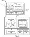
- FIG. 3is a block diagram of a further embodiment of a system for persistent memory management
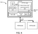
- FIG. 4is a block diagram of a system comprising a plurality of auto-commit memories
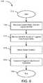
- FIG. 5is a block diagram of an auto-commit memory implemented with a commit management apparatus
- FIG. 6is a block diagram of another embodiment of a system for persistent memory management
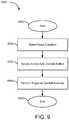
- FIG. 7is a flow diagram of one embodiment of a method for auto-commit memory
- FIG. 8is a flow diagram of another embodiment of a method for auto-commit memory
- FIG. 9is a flow diagram of another embodiment of a method for auto-commit memory
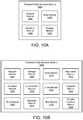
- FIG. 10Ais a schematic block diagram illustrating one embodiment of a persistent data structure module
- FIG. 10Bis a schematic block diagram illustrating another embodiment of a persistent data structure module
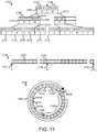
- FIG. 11is a schematic block diagram illustrating one embodiment of a mapping structure, a sparse logical address space, and a log-based writing structure
- FIG. 12is a schematic flow chart diagram illustrating one embodiment of a method for a persistent data structure
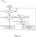
- FIG. 13is a schematic flow chart diagram illustrating another embodiment of a method for a persistent data structure
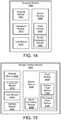
- FIG. 14is a schematic block diagram illustrating one embodiment of a snapshot module
- FIG. 15is a schematic block diagram illustrating one embodiment of a multiple interface module
- FIG. 16is a schematic flow chart diagram illustrating one embodiment of a method for a persistent queue data structure
- FIG. 17is a schematic flow chart diagram illustrating one embodiment of a method for replicating a persistent data structure
- FIG. 18is a schematic flow chart diagram illustrating one embodiment of a method for a barrier operation.
- FIG. 19is a schematic flow chart diagram illustrating one embodiment of a method for multiple serializing interfaces.
- modulesmay be implemented as a hardware circuit comprising custom VLSI circuits or gate arrays, off-the-shelf semiconductors such as logic chips, transistors, or other discrete components.
- a modulemay also be implemented in programmable hardware devices such as field programmable gate arrays, programmable array logic, programmable logic devices or the like.
- Modulesmay also be implemented in software for execution by various types of processors.
- An identified module of executable codemay, for instance, comprise one or more physical or logical blocks of computer instructions which may, for instance, be organized as an object, procedure, or function. Nevertheless, the executables of an identified module need not be physically located together, but may comprise disparate instructions stored in different locations which, when joined logically together, comprise the module and achieve the stated purpose for the module.
- a module of executable codemay be a single instruction, or many instructions, and may even be distributed over several different code segments, among different programs, and across several memory devices.
- operational datamay be identified and illustrated herein within modules, and may be embodied in any suitable form and organized within any suitable type of data structure. The operational data may be collected as a single data set, or may be distributed over different locations including over different storage devices, and may exist, at least partially, merely as electronic signals on a system or network.
- the software portionsare stored on one or more computer readable media.
- the depicted componentsare part of the storage device 102
- at least a portion of one or more of the storage controller 104 , the persistent data structure module 1009 , the auto-commit memory 1011 , or the likemay be located on the host 114 , as computer executable code, a device driver, an operating system, or the like.
- non-volatile memory 110is referred to herein as “memory media,” in various embodiments, the non-volatile memory 110 may more generally comprise a non-volatile recording media capable of recording data, the non-volatile recording media may be referred to as a non-volatile memory media, a non-volatile storage media, or the like. Further, the non-volatile storage device 102 , in various embodiments, may comprise a non-volatile recording device, a non-volatile memory device, a non-volatile storage device, or the like.
- the storage device 102implements a write data pipeline 106 and a read data pipeline 108 , an example of which is described in greater detail below with regard to FIG. 3 .
- the write data pipeline 106may perform certain operations on data as the data is transferred from the host 114 into the non-volatile memory 110 . These operations may include, for example, error correction code (ECC) generation, encryption, compression, and others.
- ECCerror correction code
- the read data pipeline 108may perform similar and potentially inverse operations on data that is being read out of non-volatile memory 110 and sent to the host 114 .
- the secondary power supply 124may include one or more batteries, one or more capacitors, a bank of capacitors, a separate connection to a power supply, or the like. In one embodiment, the secondary power supply 124 provides power to the storage device 102 for at least a power hold-up time during a power disruption or other reduction in power from the primary power connection 130 . The secondary power supply 124 , in a further embodiment, provides a power hold-up time long enough to enable the storage device 102 to flush data that is not in non-volatile memory 110 into the non-volatile memory 110 . As a result, the storage device 102 can preserve the data that is not permanently stored in the storage device 102 before the lack of power causes the storage device 102 to stop functioning.
- the secondary power supply 124may comprise the smallest capacitors possible that are capable of providing a predefined power hold-up time to preserve space, reduce cost, and simplify the storage device 102 .
- one or more banks of capacitorsare used to implement the secondary power supply 124 as capacitors are generally more reliable, require less maintenance, and have a longer life than other options for providing secondary power.
- the storage device 102sends an acknowledgement to the host 114 at some point after the storage device 102 receives data to be stored in the non-volatile memory 110 .
- the write data pipeline 106may generate the acknowledgement. It is advantageous for the storage device 102 to send the acknowledgement as soon as possible after receiving the data.
- the write data pipeline 106sends the acknowledgement before data is actually stored in the non-volatile memory 110 .
- the write data pipeline 106may send the acknowledgement while the data is still in transit through the write data pipeline 106 to the non-volatile memory 110 .
- PCI-eindicates that, in the event that a power disruption is signaled, data should be assumed corrupted and not stored in certain circumstances. Similar potential corruption may occur for storage devices 102 connected to hosts 114 using other connection types, such as PCI, serial advanced technology attachment (serial ATA or SATA), parallel ATA (PATA), small computer system interface (SCSI), IEEE 1394 (FireWire), Fiber Channel, universal serial bus (USB), PCIe-AS, or the like.
- SATAserial advanced technology attachment
- PATAparallel ATA
- SCSIsmall computer system interface
- IEEE 1394FireWire
- Fiber Channelfiber Channel
- USBuniversal serial bus
- PCIe-ASPCIe-AS
- the lag between the power disruption occurring and the auto-commit memory 1011 discovering the power disruptioncan allow corrupt data to enter the write data pipeline 106 .
- this corrupt datashould be identified and not stored to the non-volatile memory 110 .
- this corrupt datacan be stored in the non-volatile memory 110 and marked as corrupt as described below.
- identifying corrupt data and not storing the data to the non-volatile memory 110will be primarily used to describe the functions and features herein.
- the host 114should be aware that this data was not stored, or alternatively data for which integrity is a question is not acknowledged until data integrity can be verified. As a result, corrupt data should not be acknowledged.
- the storage device 102also includes the auto-commit memory 1011 .
- the auto-commit memory 1011is in communication with, managed by, or at least partially integrated with the storage controller 104 .
- the auto-commit memory 1011may, for instance, cooperate with a software driver and/or firmware for the storage device 102 .
- at least a portion of the auto-commit memory 1011is implemented on the storage device 102 , so that the auto-commit memory 1011 continues to function during a partial or complete power loss using power from the secondary power supply 124 , even if the host 114 is no longer functioning.
- the auto-commit memory 1011initiates a power loss mode in the storage device 102 in response to a reduction in power from the primary power connection 130 .
- the auto-commit memory 1011flushes data that is in the storage device 102 that is not yet stored in non-volatile memory 110 into the non-volatile memory 110 .
- the auto-commit memory 1011flushes the data that has been acknowledged and is in the storage device 102 that is not yet stored in non-volatile memory 110 into the non-volatile memory 110 .
- the auto-commit memory 1011may adjust execution of data operations on the storage device 102 to ensure that essential operations complete before the secondary power supply 124 loses sufficient power to complete the essential operations, i.e. during the power hold-up time that the secondary power supply 124 provides.
- the essential operationscomprise those operations for data that has been acknowledged as having been stored, such as acknowledged write operations. In other embodiments, the essential operations comprise those operations for data that has been acknowledged as having been stored and erased. In other embodiments, the essential operations comprise those operations for data that have been acknowledged as having been stored, read, and erased.
- the auto-commit memory 1011may also terminate non-essential operations to ensure that those non-essential operations do not consume power unnecessarily and/or do not block essential operations from executing; for example, the auto-commit memory 1011 may terminate erase operations, read operations, unacknowledged write operations, and the like.
- the auto-commit memory 1011may also be responsible for determining what data was corrupted by the power disruption, preventing the corrupt data from being stored in non-volatile memory 110 , and ensuring that the host 114 is aware that the corrupted data was never actually stored on the storage device 102 . This prevents corruption of data in the storage device 102 resulting from the power disruption.
- the system 100includes a plurality of storage devices 102 .
- the auto-commit memory 1011manages power loss modes for each storage device 102 in the plurality of storage devices 102 , providing a system-wide power loss mode for the plurality of storage devices 102 .
- each storage device 102 in the plurality of storage devices 102includes a separate auto-commit memory 1011 that manages a separate power loss mode for each individual storage device 102 .
- the auto-commit memory 1011may quiesce or otherwise shut down one or more storage devices 102 of the plurality of storage devices 102 to conserve power from the secondary power supply 124 for executing essential operations on one or more other storage devices 102 .
- the system 100includes one or more adapters for providing electrical connections between the host 114 and the plurality of storage devices 102 .
- An adapterin various embodiments, may include a slot or port that receives a single storage device 102 , an expansion card or daughter card that receives two or more storage devices 102 , or the like.
- the plurality of storage devices 102may each be coupled to separate ports or slots of the host 114 .
- one or more adapters, such as daughter cards or the likemay be electrically coupled to the host 114 (i.e. connected to one or more slots or ports of the host 114 ) and the one or more adapters may each provide connections for two or more storage devices 102 .
- the system 100includes a circuit board, such as a motherboard or the like, that receives two or more adapters, such as daughter cards or the like, and each adapter receives two or more storage devices 102 .
- the adaptersare coupled to the circuit board using PCI-e slots of the circuit board and the storage devices 102 are coupled to the adapters using PCI-e slots of the adapters.
- the storage devices 102each comprise a dual in-line memory module (DIMM) of non-volatile solid-state storage, such as Flash memory, or the like.
- the circuit board, the adapters, and the storage devices 102may be external to the host 114 , and may include a separate primary power connection 130 .
- the secondary power supply 124provides electric power to each of a plurality of storage devices 102 .
- the secondary power supply 124may be disposed in a circuit on a main circuit board or motherboard and may provide power to several adapters.
- the system 100includes a plurality of secondary power supplies that each provide electric power to a subset of a plurality of storage devices 102 .
- each adaptermay include a secondary power supply 124 for storage devices 102 of the adapter.
- each storage device 102may include a secondary power supply 124 for the storage device 102 .
- one of skill in the artwill recognize different arrangements of secondary power supplies 124 for providing power to a plurality of storage devices 102 .
- the systems, methods, and apparatus described abovemay be leveraged to implement an auto-commit memory capable of implementing memory semantic write operations (e.g., persistent writes) at CPU memory write granularity and speed.
- memory semantic write operationse.g., persistent writes
- volatile memorysuch as DRAM, SRAM, BRAM, or the like, may be used as, considered, or represented as non-volatile.
- the auto-commit memory described hereinmay be configured to ensure or guarantee that data is preserved or persisted, even while the data is stored in a volatile auto-commit memory buffer.
- the volatile auto-commit memory buffers, elements, modules, or devices described hereinmay be armed or associated with auto-commit metadata defining a commit action for the auto-commit memory module 1011 to perform in response to a trigger.
- memory semantic operationsrefers to operations having a granularity, synchronicity, and access semantics of volatile memory accesses, using manipulatable memory pointers, or the like.
- Memory semantic operationsmay include, but are not limited to: load, store, peek, poke, write, read, set, clear, and so on.
- Memory semantic operationsmay operate at a CPU-level of granularity (e.g., single bytes, words, cache lines, or the like), and may be synchronous (e.g., the CPU waits for the operation to complete).
- providing access at a larger sized granularity, such as cache linesmay increase access rates, provide more efficient write combining, or the like than smaller sized granularity access.
- the ACM 1011may be available to computing devices and/or applications (both local and remote) using one or more of a variety of memory mapping technologies, including, but not limited to, memory mapped I/O (MMIO), port I/O, port-mapped IO (PMIO), Memory mapped file I/O, and the like.
- MMIOmemory mapped I/O
- PMIOport-mapped IO
- BARPCI-e Base Address Register
- ACM 1011may also be directly accessible via a memory bus of a CPU, using an interface such as a double data rate (DDR) memory interface, HyperTransport, QuickPath Interconnect (QPI), or the like.
- DDRdouble data rate
- QPIQuickPath Interconnect
- the ACM 1011may be accessible using memory access semantics, such as CPU load/store, direct memory access (DMA), 3 rd party DMA, remote DMA (RDMA), atomic test and set, and so on.
- DMAdirect memory access
- RDMAremote DMA
- the direct, memory semantic access to the ACM 1011 disclosed hereinallows many of the system and/or virtualization layer calls typically required to implement committed operations to be bypassed, (e.g., call backs via asynchronous Input/Output interfaces may be bypassed).
- an ACM 1011may be mapped to one or more virtual ranges (e.g., virtual BAR ranges, virtual memory addresses, or the like).
- the virtual mappingmay allow multiple computing devices and/or applications to share a single ACM address range 1021 (e.g., access the same ACM simultaneously, within different virtual address ranges).
- An ACM 1011may be mapped into an address range of a physical memory address space addressable by a CPU so that the CPU may use load/store instructions to read and write data directly to the ACM 1011 using memory semantic accesses.
- a CPUin a further embodiment, may map the physically mapped ACM 1011 into a virtual memory address space, making the ACM 1011 available to user-space processes or the like as virtual memory.
- the ACM 1011may be pre-configured to commit its contents upon detection of a restart condition (or other pre-determined triggering event) and, as such, operations performed on the ACM 1011 may be viewed as being “instantly committed.”
- an applicationmay perform a “write-commit” operation on the ACM 1011 using memory semantic writes that operate at CPU memory granularity and speed, without the need for separate corresponding “commit” commands, which may significantly increase the performance of applications affected by write-commit latencies.
- a write-commit operationis an operation in which an application writes data to a memory location (e.g., using a memory semantic access), and then issues a subsequent commit command to commit the operation (e.g., to persistent storage or other commit mechanism).
- each write-commit operationmay comprise its own separate commit command. For example, in a database logging application, each log transaction must be written and committed before a next transaction is logged. Similarly, messaging systems (e.g., store and forward systems) must write and commit each incoming message, before receipt of the message can be acknowledged.
- a virtual memory systeme.g., using a memory backed file.
- the applicationperforms high-performance memory semantic write operations in system RAM, but, in order to commit the operations, must perform subsequent “commit” commands to persist each write operation to the backing file (or other persistent storage).
- each write-commit operationmay comprise its own separate commit command. For example, in a database logging application, each log transaction must be written and committed before a next transaction is logged. Similarly, messaging systems (e.g., store and forward systems) must write and commit each incoming message, before receipt of the message can be acknowledged.
- the write-commit latencytherefore, comprises a relatively fast memory semantic write followed by a much slower operation to commit the data to persistent storage.
- Write-commit latencymay include several factors including, access times to persistent storage, system call overhead (e.g., translations between RAM addresses, backing store LBA, etc.), and so on.
- Examples of applications that may benefit from reduced write-commit latencyinclude, but are not limited to: database logging applications, file system logging, messaging applications (e.g., store and forward), semaphore primitives, and so on.
- the systems, apparatus, and methods for persistent data structures using auto-commit memory disclosed hereinmay be used to significantly increase the performance of write-commit latency bound applications by providing direct access to a memory region at any suitable level of addressing granularity including byte level, page level, cache-line level, or other memory region level, that is guaranteed to be committed in the event of a system failure or other restart event, without the application issuing a commit command. Accordingly, the write-commit latency of an application may be reduced to the latency of a memory semantic access (a single write over a system bus).
- the persistent data structure module 1009may use or cooperate with the auto-commit memory 1011 , as described herein, to provide persistent data structures to clients (e.g., an operating system, virtual operating platform, guest operating system, application, database system, process, thread, entity, utility, user, or the like) with many of the benefits and speed of volatile memory and the persistence of the non-volatile memory medium 110 .
- clientse.g., an operating system, virtual operating platform, guest operating system, application, database system, process, thread, entity, utility, user, or the like
- a data structurecomprises an organized arrangement, group, or set of data.
- a data structuremay be organized according to a predefined pattern or schema, may comprise metadata such as pointers, sequence numbers, labels, identifiers, or the like to facilitate organization of and access to the included data.
- Data structuresmay include, but are not limited to, a log (e.g., a sequential log, a transaction log, an application log), a queue (e.g., a first-in-first-out or FIFO queue, a buffer, a priority queue), a stack (e.g.
- a last-in-first-out or LIFO stack, a priority stacke.g., a tree (e.g., a binary tree, B ⁇ tree, B+ tree, B* tree, ternary tree, K-ary tree, space-partitioning tree, decision tree), a linked-list (e.g., singly linked list, doubly linked list, self-organizing list, doubly connected edge list), a hash (e.g., a hash list, hash table, hash tree, hash array), an array (e.g., a table, map, bit array, bit field, bitmap, matrix, sparse array), a heap (e.g., a binary heap, binomial heap, Fibonacci heap, ternary heap, D-ary heap), a graph (e.g., directed graph, directed acyclic graph, binary decision diagram, graph-structured stack, multigraph, hypergraph, adjacency list), or the like.
- a hashe.g., has
- a transaction log(e.g., a transaction journal, a database log, a binary log, an audit trail, a sequential log, an application log), in certain embodiments, includes sequential, historical, or chronological entries, such as a history or list of updates made to a database or database table, transactions executed by a database or other application, or the like.
- a transaction logmay include enough information regarding each transaction to either rollback or undo the transaction, or to redo or reapply the transaction.
- a transaction logmay include sequence information for each entry or transaction, such as a timestamp, a sequence number, a link to a previous or next entry, or the like.
- a transaction logmay also include other types of metadata, such as a transaction identifier (e.g., a reference to a database transaction that generated the log record), a type (e.g., a label describing the type of database log record), or the like. While a persistent transaction log is primarily described herein with regard to the persistent data structure module 1009 , the description is equally applicable to other types of data structures, such as the example data structures listed above.
- a transaction identifiere.g., a reference to a database transaction that generated the log record
- typee.g., a label describing the type of database log record
- the persistent data structure module 1009may provide an interface, such as an application programming interface (API), shared library, hardware interface, a communications bus, one or more IO control (IOCTL) commands, or the like, over which a client may create, update, delete, or otherwise access one or more types of persistent data structures.
- APIapplication programming interface
- IOCTLIO control
- a data structure, as used herein,is persistent if the data structure remains accessible to a client in some form after a restart event, which may be ensured or guaranteed by the auto-commit memory 1011 , as described herein.
- the persistent data structure module 1009may associate a persistent logical identifier with a persistent data structure, which a client may use to access the persistent data structure both before and after a restart event.
- a persistent data structure module 1009may cooperate with a file system module 1558 as described below with regard to FIG. 6 to provide access to a persistent data structure as a file system file with a filename, a filename and an offset, or the like.
- a persistent logical identifiermay comprise a logical unit number (LUN) identifier (ID) from a LUN namespace, a LUN ID and an offset, a logical identifier for a persistent memory namespace for the ACM 1011 as described below, a logical block address (LBA) or LBA range from a namespace of the non-volatile memory device 102 , or another persistent logical identifier.
- LUNlogical unit number
- LBAlogical block address
- LBAlogical block address
- the persistent data structure module 1009may cooperate with the ACM 1011 to destage, copy, transfer, migrate, and/or move data from ACM buffers of the ACM 1011 to the non-volatile memory medium 110 (e.g., in the background) at a transfer rate that matches or exceeds the input rate over time, so that the data does not overrun the one or more ACM buffers allocated to the data structure.
- the persistent data structure module 1009may block, delay, throttle, govern, or otherwise limit the input rate at which a client writes data to a data structure. In this manner, the persistent data structure module 1009 may mask or hide the ACM 1011 and/or non-volatile memory medium 110 from a client such that the client perceives the access speed and benefits of the ACM 1011 and the persistence of the non-volatile memory medium 110 , without being aware of the complexities of the tiered architecture that the persistent data structure module 1009 uses to provide these benefits.
- the persistent data structure module 1009may enforce one or more rules for a data structure.
- each different type of data structuremay be defined or structured by a set of one or more rules, restrictions, definitions, or the like.
- the rulesmay define one or more allowed or acceptable data operations for a data structure.
- the rulesmay include that entries must be sequential, that data entries may not be overwritten or updated once written, or the like.
- Different types of data structuresmay have different rules.
- a queuemay have a strict FIFO rule
- a stackmay have a strict LIFO rule
- a treemay have a rule defining a strict order or hierarchy for data entries or nodes
- a data structuremay have a rule requiring certain data types or required fields or entries, or the like.
- the persistent data structure module 1009may prevent an application or other client from inadvertently or accidently overwriting or otherwise violating the integrity of a persistent data structure, ensuring that the persistent data structure satisfies the data structure's strict definition, or the like.
- the persistent data structure module 1009provides data structures that are non-volatile or persistent, errors in data structure integrity (e.g., an overwritten data structure, an improper entry in a data structure, or the like) would otherwise persist after a restart event or reboot, and would not be cleared or reset as would errors in a volatile data structure.
- errors in data structure integritye.g., an overwritten data structure, an improper entry in a data structure, or the like
- the persistent data structure module 1009may provide an interface or library that integrates with and/or provides an operating system, a file system, one or more applications or other clients, or the like access to the hardware capabilities of the ACM 1011 and/or the non-volatile memory medium 110 in a substantially transparent manner, thereby providing persistent data structures accessible via a library, a filename or other persistent logical identifier, or the like.
- the persistent data structure module 1009manages the tiered hierarchy of the ACM 1011 , the non-volatile memory medium 110 (e.g., the storage management layer described below), a file system (e.g., the file system module 1558 described below), in one embodiment, the persistent data structure module 1009 may provide the benefits of the ACM 1011 for persistent data structures, even with a small amount of volatile memory for the ACM 1011 (e.g., ACM buffers) relative to storage capacity of the non-volatile memory medium 110 .
- a small amount of volatile memory for the ACM 1011e.g., ACM buffers
- FIG. 2is a block diagram of a system 1000 comprising one embodiment of a persistent data structure module 1009 and an auto-commit memory (ACM) 1011 .
- an auto-commit memorycomprises low-latency, high reliability memory media, exposed to the persistent data structure module 1009 and/or other ACM users for direct memory semantic access, at a memory semantic access and address granularity level of at least byte level, combined with logic and components together configured to restore the same state of data stored in the ACM 1011 that existed prior to the restart event and the same level of memory semantic access to data stored in the auto-commit memory after a restart event.
- the ACM 1011guarantees that data stored in the ACM 1011 will be accessible after a restart event.
- the ACM 1011when data is written to the ACM 1011 , it may not initially be “committed” per se (is not necessarily stored on a persistent memory media and/or state); rather, a pre-configured process is setup to preserve the ACM data and its state, if a restart event occurs while the ACM data is stored in the ACM 1011 .
- the pre-configuring of this restart survival processis referred to herein as “arming.”
- the ACM 1011may be capable of performing the pre-configured commit action autonomously and with a high degree of assurance, despite the system 1000 experiencing failure conditions or another restart event.
- an entity that stores data on the ACM 1011may consider the data to be “instantaneously committed” or safe from loss or corruption, at least as safe as if the data were stored in a non-volatile storage device such as a hard disk drive, tape storage media, or the like.
- the ACM 1011may be accessible to one or more computing devices, such as the host 1014 .
- a computing devicerefers to a computing device capable of accessing an ACM.
- the host 1014may be a computing device that houses the ACM 1011 as a peripheral; the ACM 1011 may be attached to a system bus 1040 of the host 1014 ; the ACM 1011 may be in communication with the host 1014 over a data network; and/or the ACM 1011 may otherwise be in communication with the host 1014 .
- the host 1014in certain embodiments, may access the ACM 1011 hosted by another computing device.
- the accessmay be implemented using any suitable communication mechanism, including, but not limited to: CPU programmed IO (CPIO), port-mapped IO (PMIO), memory-mapped IO (MMIO), a Block interface, a PCI-e bus, Infiniband, RDMA, or the like.
- the host 1014may comprise one or more ACM users 1016 .
- an ACM user 1016refers to any operating system (OS), virtual operating platform (e.g., an OS with a hypervisor), a guest OS, application, process, thread, entity, utility, user, or the like, that is configured to access the ACM 1011 .
- OSoperating system
- virtual operating platforme.g., an OS with a hypervisor
- guest OSapplication, process, thread, entity, utility, user, or the like
- the ACM 1011may be physically located at one or more levels of the host 1014 .
- the ACM 1011may be connected to a PCI-e bus and may be accessible to the host 1014 with MMIO.
- the ACM 1011may be directly accessible to a CPU of the host 1014 via a memory controller.
- the ACM 1011may be directly attached to and/or directly (e.g., Quick Path Interconnect (QPI)) in communication with a CPU of the host 1014 or the like.
- QPIQuick Path Interconnect
- Volatile media of the ACM 1011 and non-volatile backing media of the ACM 1011may not be physically co-located within the same apparatus, but may be in communication over a communications bus, a data network, or the like.
- hardware components of the ACM 1011may be tightly coupled, and integrated in a single physical hardware apparatus.
- Volatile memory media and/or non-volatile memory media of the ACM 1011in one embodiment, may be integrated with, or may otherwise cooperate with, a CPU cache hierarchy of the host 1014 , to take advantage of CPU caching technologies such as write combining or the like.
- One or more ACM buffers 1013may be mapped into an address range of a physical memory address space addressable by a CPU, a kernel, or the like of the host device 1014 , such as the memory system 1018 described below.
- one or more ACM buffers 1013may be mapped as directly attached physical memory, as MMIO addressable physical memory over a PCI-e bus, or otherwise mapped as one or more pages of physical memory.
- At least a portion of the physically mapped ACM buffers 1013in a further embodiment, may be mapped into a virtual memory address space, accessible to user-space processes or the like as virtual memory.
- Allowing ACM users 1016 to directly address the ACM buffers 1013bypasses one or more layers of the traditional operating system memory stack of the host device 1014 , providing direct load/store operation access to kernel-space and/or user-space applications.
- An operating systemusing a kernel module, an application programming interface, the storage management layer (SML) 1050 described below, or the like, in one embodiment, maps and unmaps ACM buffers 1013 to and from the memory system 1018 for one or more ACM users 1016 , and the ACM users 1016 may directly access an ACM buffer 1013 once the operating system maps the ACM buffer 1013 into the memory system 1018 .
- the operating systemmay also service system flush calls for the ACM buffers 1013 , or the like.
- the ACM 1011may perform a commit action for each ACM buffer 1013 associated with the flush request.
- Each ACM buffer 1013is committed as indicated by the ACM metadata 1015 of the associated ACM buffer 1013 .
- a flush functionin various embodiments, may be specific to one or more ACM buffers 1013 , system-wide for all ACM buffers 1013 , or the like.
- a CPU, an operating system, or the like for the host 1014may request an ACM flush operation in response to, or as part of a CPU cache flush, a system-wide data flush for the host 1014 , or another general flush operation.
- An ACM user 1016may request a flush operation to maintain data consistency prior to performing a maintenance operation, such as a data snapshot or a backup, to commit ACM data prior to reallocating an ACM buffer 1013 , to prepare for a scheduled restart event, or for other circumstances where flushing data from an ACM buffer 1013 may be beneficial.
- a maintenance operationsuch as a data snapshot or a backup
- An ACM user 1016may request that the ACM 1011 map and/or unmap one or more ACM buffers 1013 to perform memory management for the ACM buffers 1013 ; to reallocate the ACM buffers 1013 between applications or processes; to allocate ACM buffers 1013 for new data, applications, or processes; to transfer use of the ACM buffers 1013 to a different host 1014 (in shared ACM 1011 embodiments); or to otherwise manipulate the memory mapping of the ACM buffers 1013 .
- the storage management module 1050may dynamically allocate, map, and/or unmap ACM buffers 1013 using a resource management agent as described below.
- the host 1014may view data written to the ACM 1011 as being instantaneously “committed” or non-volatile, as the host 1014 or ACM user 1016 may access the data both before and after the trigger event.
- the restart eventmay cause the ACM user 1016 to be re-started or re-initialized the data stored in the ACM 1011 is in the same state/condition after the restart event as it was before the restart event.
- the host 1014may, therefore, write to the ACM 1011 using memory write semantics (and at CPU speeds and granularity), without the need for explicit commit commands by relying on the pre-configured trigger of the ACM 1011 to commit the data in the event of a restart (or other trigger event).
- the ACM 1011may comprise a plurality of auto-commit buffers 1013 , each comprising respective ACM metadata 1015 .
- the ACM metadata 1015may include data to facilitate committing of ACM data in response to a triggering event for the auto-commit buffer 1013 , such as a logical identifier for data in the ACM buffer 1013 , an identifier of a commit agent 1020 , instructions for a commit process or other processing procedure, security data, or the like.
- the auto-commit buffers 1013may be of any suitable size, from a single sector, page, byte, or the like, to a virtual or logical page size (e.g., 80 to 400 kb).
- the size of the auto-commit buffers 1013may be adapted according to the storage capacity of the underlying non-volatile storage media 110 , 1110 , 1510 , and or hold-up time available from the secondary power supply 1024 .
- the ACM buffers 1013may comprise volatile memory backed by the non-volatile memory media 110 , 1110 , 1510 or may comprise natively non-volatile memory media.
- Volatile memory, volatile memory buffers, volatile memory modules, volatile memory elements, or the like, as used herein,may refer to just the volatile memory media of the ACM buffers 1013 (e.g., chips, dies, DIMMs, or the like of volatile memory) or to the ACM 1011 as a whole, including one or more of the ACM buffers 1013 , the storage controller 104 , 1004 , 1104 or other logic, and/or the secondary power supply 124 , 1024 , 1324 .
- the ACM buffer 1013may comprise independent memory media (e.g., chips, dies, DIMMs, or the like of volatile memory) or may be integrated with the storage controller 104 , 1004 , 1104 .
- the storage controller 104 , 1004 , 1104comprises a field programmable gate array (FPGA) or other programmable logic
- one or more of the ACM buffers 1013may comprise dedicated RAM or other volatile memory of the programmable logic, may comprise logic gates of the programmable logic configured as volatile memory, or the like.
- the ACM 1011may dynamically move the ACM data and ACM metadata 1015 from the ACM buffers 1013 to the associated LBAs of the non-volatile memory 110 , freeing storage capacity of the ACM buffers 1013 to provide a larger storage capacity.
- the ACM 1011may further return the ACM data and ACM metadata 1015 back to one or more ACM buffers 1013 as ACM buffers become available, certain addresses outside the data of currently loaded ACM buffers 1013 is requested, or the like, managing storage capacity of the ACM buffers 1013 .
- the ACM 1011is pre-configured or “armed” to implement one or more “triggered commit actions” in response to a restart condition (or other, pre-determined condition).
- a restart condition or eventmay include, but is not limited to a software or hardware shutdown/restart of a host 1014 , a failure in a host 1014 computing device, a failure of a component of the host 1014 (e.g., failure of the bus 1040 ), a software fault (e.g., an fault in software running on the host 1014 or other computing device), a loss of the primary power connection 1030 , an invalid shutdown, or another event that may cause the loss of data stored in a volatile memory.
- a restart eventcomprises the act of the host 1014 commencing processing after an event that can cause the loss of data stored within a volatile memory of the host 1014 or a component in the host 1014 .
- the host 1014may commence/resume processing once the restart condition or event has finished, a primary power source is available, and the like.
- the ACM 1011is configured to detect that a restart event/condition has occurred and/or respond to a restart event by initiating a recovery stage. During a recovery stage, the ACM 1011 may restore the data of the ACM 1011 to the state prior to the restart event. Alternatively, or in addition, during the recovery stage, the ACM 1011 may complete processing of ACM data or ACM metadata 1015 needed to satisfy a guarantee that data in the ACM 1011 is available to ACM users after the restart event. Alternatively, or in addition, during the recovery stage, the ACM 1011 may complete processing of ACM data or ACM metadata 1015 needed to satisfy a guarantee that data in the ACM 1011 is committed after the restart event.
- “commit”means data in the ACM 1011 is protected from loss or corruption even after the restart event and is persisted as required per the arming information associated with the data.
- the recovery stageincludes processing ACM data and ACM metadata 1015 such that the ACM data is persisted, even though the restart event occurred.
- a triggered commit actionis a pre-configured commit action that is armed to be performed by the ACM 1011 in response to a triggering event (e.g., a restart event, a flush command, or other pre-determined event).
- a triggering evente.g., a restart event, a flush command, or other pre-determined event.
- the triggered commit actionpersists at least enough ACM data and/or ACM metadata 1015 to make data of the ACM 1011 available after a system restart, to satisfy a guarantee of the ACM 1011 that the data will be accessible to an ACM user after a restart event, in certain embodiments, this guarantee is satisfied, at least in part, by committing and/or persisting data of the ACM 1011 to non-volatile memory media.
- a triggered commit actionmay be completed before, during, and/or after a restart event.
- the ACM 1011may write ACM data and ACM metadata 1015 to a predefined temporary location in the non-volatile memory 110 during a hold-up time after a restart event, and may copy the ACM data back into the ACM buffers 1013 , to an intended location in the non-volatile memory 110 , or perform other processing once the restart event is complete.
- a triggered commit actionmay be “armed” when the ACM 1011 is requested and/or a particular ACM buffer 1013 is allocated for use by a host 1014 .
- an ACM 1011may be configured to implement a triggered commit action in response to other, non-restart conditions. For example, an operation directed to a particular logical address (e.g., a poke), may trigger the ACM 1011 , a flush operation may trigger the ACM 1011 , or the like. This type of triggering may be used to commit the data of the ACM 1011 during normal operation (e.g., non-restart or non-failure conditions).
- the armingmay occur when an auto-commit buffer 1013 is mapped into the memory system 1018 of the host 1014 . Alternatively, arming may occur as a separate operation. As used herein, arming an auto-commit buffer 1013 comprises performing the necessary configuration steps needed to complete the triggered action when the action is triggered. Arming may include, for example, providing the ACM metadata 1015 to the ACM 1011 or the like. In certain embodiments, arming further includes performing the necessary configuration steps needed to complete a minimal set of steps for the triggered action, such that the triggered action is capable of completing after a trigger event.
- armingfurther includes verifying the arming data (e.g., verifying that the contents of the auto-commit buffer 1013 , or portion thereof, can be committed as specified in the ACM metadata 1015 ) and verifying that the ACM 1011 is capable and configured to properly perform the triggered action without error or interruption.
- verifying the arming datae.g., verifying that the contents of the auto-commit buffer 1013 , or portion thereof, can be committed as specified in the ACM metadata 1015 .
- the verificationmay ensure that once armed, the ACM 1011 can implement the triggered commit action when required. If the ACM metadata 1015 cannot be verified (e.g., the logical identifier or other ACM metadata 1015 is invalid, corrupt, unavailable, or the like), the arming operation may fail; memory semantic operations on the auto-commit buffer 1013 may not be allowed unit the auto-commit buffer 1013 is successfully armed with valid ACM metadata 1015 .
- an auto-commit buffer 1013that is backed by a hard disk having a one-to-one mapping between LBA and physical address, may fail to arm if the LBA provided for the arming operation does not map to a valid (and operational) physical address on the disk. Verification in this case may comprise querying the disk to determine whether the LBA has a valid, corresponding physical address and/or using the physical address as the ACM metadata 1015 of the auto-commit buffer 1013 .
- the armed triggered commit actionsare implemented in response to the ACM 1011 (or other entity) detecting and/or receiving notification of a triggering event, such as a restart condition.
- a triggering eventsuch as a restart condition.
- an armed commit actionis a commit action that can be performed by the ACM 1011 , and that requires no further communication with the host 1014 or other devices external to the “isolation zone” of the ACM 1011 (discussed below).
- the ACM 1011may be configured to implement triggered commit actions autonomously of the host 1014 and/or other components thereof.
- the ACM 1011may guarantee that triggered commit actions can be committed without errors and/or despite external error conditions.
- the triggered commit actions of the ACM 1011do not comprise and/or require potentially error-introducing logic, computations, and/or calculations.
- a triggered commit actioncomprises committing data stored on the volatile ACM 1011 to a persistent storage location.
- a triggered commit actionmay comprise additional processing of committed data, before, during, and/or after a triggering event, as described below.
- the ACM 1011may implement pre-configured triggered commit actions autonomously; the ACM 1011 may be capable of implementing triggered commit actions despite failure or restart conditions in the host 1014 , loss of primary power, or the like.
- the ACM 1011can implement triggered commit actions independently due to arming the ACM 1011 as described above.
- Each level of metadatamay be associated with a different commit agent 1020 , or the like.
- the ACM metadata 1015may include security data, such as a signature for an owner of the associated ACM data, a pre-shared key, a nonce, or the like, which the ACM 1011 may use during recovery to verify that a commit agent 1020 , an ACM user 1016 , or the like is authorized to access committed ACM metadata 1015 and/or associated ACM data. In this manner, the ACM 1011 may prevent ownership spoofing or other unauthorized access. In one embodiment, the ACM 1011 does not release ACM metadata 1015 and/or associated ACM data until a requesting commit agent 1020 , ACM user 1016 , or the like provides valid authentication, such as a matching signature or the like.
- One or more commit agents 1020process ACM data based on the associated ACM metadata 1015 to execute a triggered commit action.
- a commit agent 1020may comprise software, such as a device driver, a kernel module, the storage management module 1050 , a thread, a user space application, or the like, and/or hardware, such as the controller 1004 described below, that is configured to interpret ACM metadata 1015 and to process the associated ACM data according to the ACM metadata 1015 .
- the ACM metadata 1015may identify one or more commit agents 1020 to process the associated ACM data.
- the ACM metadata 1015may identify a commit agent 1020 , in various embodiments, by identifying a program/function of the commit agent 1020 to invoke (e.g., a file path of the program), by including computer executable code of the commit agent 1020 (e.g., binary code or scripts), by including a unique identifier indicating which of a set of registered commit agents 1020 to use, and/or by otherwise indicating a commit agent 1020 associated with committed ACM metadata 1015 .
- the ACM metadata 1015in certain embodiments, may be a functor or envelope which contains the information, such as function pointer and bound parameters for a commit agent 1020 , to commit the ACM data upon restart recovery.
- a primary commit agent 1020processes ACM metadata 1015 , and hands-off or transfers ACM metadata 1015 and/or ACM data to one or more secondary commit agents 1020 identified by the ACM metadata 1015 .
- a primary commit agent 1020may be integrated with the ACM 1011 , the controller 1004 , or the like.
- An ACM user 1016 or other third partymay provide a secondary commit agent 1020 for ACM data that the ACM user 1016 or other third party owns, and the primary commit agent 1020 may cooperate with the provided secondary commit agent 1020 to process the ACM data.
- the one or more commit agents 1020 for ACM dataensure and/or guarantee that the ACM data remains accessible to an owner of the ACM data after a restart event.
- a commit agent 1020may process ACM metadata 1015 and associated ACM data to perform one or more triggered commit actions before, during, and/or after a trigger event, such as a failure or other restart event.
- a commit agent 1020in cooperation with the ACM 1011 or the like, may store the ACM metadata 1015 in a persistent or non-volatile location in response to a restart or other trigger event.
- the commit agent 1020may store the ACM metadata 1015 at a known location, may store pointers to the ACM metadata 1015 at a known location, may provide the ACM metadata 1015 to an external agent or data store, or the like so that the commit agent 1020 may process the ACM metadata 1015 and associated ACM data once the restart or other trigger event has completed.
- the known locationmay include one or more predefined logical block addresses or physical addresses of the non-volatile memory 110 , a predefined file, or the like.
- hardware of the ACM 1011is configured to cooperate to write the ACM metadata 1015 and/or pointers to the ACM metadata 1015 at a known location.
- the known locationmay be a temporary location that stores the ACM data and ACM metadata 1015 until the host 1014 has recovered from a restart event and the commit agent 1020 may continue to process the ACM data and ACM metadata 1015 .
- the locationmay be a persistent location associated with the ACM metadata 1015 .
- a commit agent 1020may locate and retrieve the ACM metadata 1015 from the non-volatile memory 110 , from a predefined location or the like.
- the commit agent 1020in response to locating and retrieving the ACM metadata 1015 , locates the ACM data associated with the retrieved ACM metadata 1015 .
- the commit agent 1020in certain embodiments, may locate the ACM data in a substantially similar manner as the commit agent 1020 locates the ACM metadata 1015 , retrieving ACM data from a predefined location, retrieving pointers to the ACM data from a predefined location, receiving the ACM data from an external agent or data store, or the like.
- the ACM metadata 1015identifies the associated ACM data and the commit agent 1020 uses the ACM metadata 1015 to locate and retrieve the associated ACM data.
- the commit agent 1020may use a predefined mapping to associate ACM data with ACM metadata 1015 (e.g., the Nth piece of ACM data may be associated with the Nth piece of ACM metadata 1015 or the like), the ACM metadata 1015 may include a pointer or index for the associated ACM data, or another predefined relationship may exist between committed ACM metadata 1015 and associated ACM data.
- an external agentmay indicate to the commit agent 1020 where associated ACM data is located.
- the commit agent 1020interprets the ACM metadata 1015 and processes the associated ACM data based on the ACM metadata 1015 .
- the ACM metadata 1015may identify a block storage volume and LBA(s) where the commit agent 1020 is to write the ACM data upon recovery.
- the ACM metadata 1015may identify an offset within a file within a file system where the commit agent 1020 is to write the ACM data upon recovery.
- the ACM metadata 1015may identify an application specific persistent object where the commit agent 1020 is to place the ACM data upon recovery, such as a database record or the like.
- the ACM metadata 1015may indicate a procedure for the commit agent 1020 to call to process the ACM data, such as a delayed procedure call or the like.
- the ACM metadata 1013may identify an ACM buffer 1013 where the commit agent 1020 is to write the ACM data upon recovery.
- the ACM metadata 1015may identify one or more secondary commit agents 1020 to further process the ACM metadata 1015 and/or associated ACM data.
- a secondary commit agent 1020may process ACM metadata 1015 and associated ACM data in a substantially similar manner to the commit agent 1020 described above.
- Each commit agent 1020may process ACM data in accordance with a different level or subset of the ACM metadata 1015 , or the like.
- the ACM metadata 1015may identify a secondary commit agent 1020 , in various embodiments, by identifying a program/function of the secondary commit agent 1020 to invoke (e.g., a file path of the program), by including computer executable code of the secondary commit agent 1020 , by including a unique identifier indicating which of a set of registered secondary commit agents 1020 to use, and/or by otherwise indicating a secondary commit agent 1020 associated with committed ACM metadata 1015 .
- the ACM 1011may guarantee persistence of the ACM data and/or performance of the triggered commit action(s) defined by the ACM metadata 1015 .
- solid-state storage devicessuch as certain embodiments of the non-volatile storage device 1102
- the disclosureis not limited in this regard, and could be adapted to use any suitable recording/memory/storage device 1102 and/or recording/memory/storage media 1110 .
- the ACM 1011may be tightly coupled to the device used to perform the triggered commit actions.
- the ACM 1011may be implemented on the same device, peripheral, card, or within the same “isolation zone” as the controller 1004 and/or secondary power source 1024 .
- the tight coupling of the ACM 1011 to the components used to implement the triggered commit actionsdefines an “isolation zone,” which may provide an acceptable level of assurance (based on industry standards or other metric) that the ACM 1011 is capable of implementing the triggered auto-commit actions in the event of a restart condition.
- the isolation zone of the ACM 1011is provided by the tight coupling of the ACM 1011 with the autonomous controller 1004 and secondary power supply 1024 (discussed below).
- a globally unique identifier namespacemay be used as an ACM namespace for logical identifiers.
- the ACM 1011may process committed ACM data according to a logical identifier for the data once a restart event has completed. For example, the ACM 1011 may commit the ACM data to a logical identifier associated with a temporary location in response to a restart event, and may write the ACM data to a persistent location identified by another logical identifier during recovery after the restart event.
- the ACM 1011may be tightly coupled with the components used to implement the triggered commit actions (e.g., the ACM 1011 is implemented within an “isolation zone”), which ensures that the data on the ACM 1011 will be committed in the event of a restart condition.
- a “tight coupling”refers to a configuration wherein the components used to implement the triggered commit actions of the ACM 1011 are within the same “isolation zone,” or two or more distinct trusted “isolation zones,” and are configured to operate despite external failure or restart conditions, such as the loss of power, invalid shutdown, host 1014 failures, or the like.
- FIG. 2illustrates a tight coupling between the ACM 1011 , the auto-commit buffers 1013 , the controller 1004 , which is configured to operate independently of the host 1014 , and the secondary power source 1024 , which is configured to power the controller 1004 and the ACM 1011 (including the auto-commit buffers 1013 ) while the triggered commit actions are completed.
- Examples of a tight couplinginclude but are not limited to including the controller 1004 , the secondary power source 1024 , and the auto-commit buffers 1013 on a single printed circuit board (PCB), within a separate peripheral in electronic communication with the host 1014 , and the like.
- the ACM 1011may be tightly coupled to other a different set of components (e.g., redundant host devices, redundant communication buses, redundant controllers, alternative power supplies, and so on).
- ACM users 1016 running on the host 1014may access the ACM 1011 via a memory system 1018 of the host 1014 .
- the memory system 1018may comprise a memory management unit, virtual memory system, virtual memory manager, virtual memory subsystem (or similar memory address space) implemented by an operating system, a virtualization system (e.g., hypervisor), an application, or the like.
- a portion of the ACM 1011e.g., one or more auto-commit buffers 1013
- may be mapped into the memory system 1018such that memory semantic operations implemented within the mapped memory address range (ACM address range 1021 ) are performed on the ACM 1011 .
- the storage management module 1050may provide a SML API 1019 comprising, inter alia, an API for mapping portions of the auto-commit memory 1011 into the memory system 1018 of the host 1014 , for unmapping portions of the auto-commit memory 1011 from the memory system 1018 of the host 1014 , for flushing the ACM buffers 1013 , for accessing and managing persistent data structures using the persistent data structure module 1009 , or the like.
- the storage management module 1050may be configured to maintain metadata 1051 , which may include a forward index 1053 comprising associations between logical identifiers of a logical address space and physical storage locations on the auto-commit memory 1011 and/or persistent storage media.
- the SML API 1019may comprise interfaces for mapping an auto-commit buffer 1013 into the memory system 1018 .
- the SML API 1019may extend existing memory management interfaces, such as malloc, calloc, or the like, to map auto-commit buffers 1013 into the virtual memory range of ACM user applications 1016 (e.g., a malloc call through the SML API 1019 may map one or more auto-commit buffers 1013 into the memory system 1018 ).
- the SML API 1019may comprise one or more explicit auto-commit mapping functions, such as “ACM_alloc,” “ACM_free,” or the like.
- the association between the ACM address range 1021 within the host memory system 1018 and the ACM 1011may be such that memory semantic operations performed within a mapped ACM address range 1021 are implemented directly on the ACM 1011 (without intervening system RAM, or other intermediate memory, in a typical write commit operation, additional layers of system calls, or the like).
- a memory semantic write operation implemented within the ACM address range 1021may cause data to be written to the ACM 1011 (on one or more of the auto-commit buffers 1013 ).
- mapping the ACM address range 1021may comprise disabling caching of memory operations within the ACM address range 1021 , such that memory operations are performed on an ACM 1011 and are not cached by the host (e.g., cached in a CPU cache, in host volatile memory, or the like).
- Disabling caching within the ACM address range 1021may comprise setting a “non-cacheable” flag attribute associated with the ACM range 1021 , when the ACM range 1021 is defined.
- establishing an association between the host memory system 1018 and the ACM 1011may comprise “arming” the ACM 1011 to implement a pre-determined triggered commit action.
- the armingmay comprise providing the ACM 1011 with a logical identifier (e.g., a logical block address, a file name, a network address, a stripe or mirroring pattern, or the like).
- the ACM 1011may use the logical identifier to arm the triggered commit action.
- the ACM 1011may be triggered to commit data to a persistent storage medium using the logical identifier (e.g., the data may be stored at a physical address corresponding to the logical identifier and/or the logical identifier may be stored with the data in a log-based data structure). Arming the ACM 1011 allows the host 1014 to view subsequent operations performed within the ACM address range 1021 (and on the ACM 1011 ) as being “instantly committed,” enabling memory semantic write granularity (e.g., byte level operations) and speed with instant commit semantics.
- memory semantic write granularitye.g., byte level operations
- Memory semantic writes such as a “store” operation for a CPUare typically synchronous operations such that the CPU completes the operation before handling a subsequent operation. Accordingly, memory semantic write operations performed in the ACM memory range 1021 can be viewed as “instantly committed,” obviating the need for a corresponding “commit” operation in the write-commit operation, which may significantly increase the performance of ACM users 1016 affected by write-commit latency.
- the memory semantic operations performed within the ACM memory range 1021may be synchronous. Accordingly, ACM 1011 may be configured to prevent the memory semantic operations from blocking (e.g., waiting for an acknowledgement from other layers, such as the bus 1040 , or the like). Moreover, the association between ACM address range 1021 and the ACM 1011 allow memory semantic operations to bypass system calls (e.g., separate write and commit commands and their corresponding system calls) that are typically included in write-commit operations.
- system callse.g., separate write and commit commands and their corresponding system calls
- Data transfer between the host 1014 and the ACM 1011may be implemented using any suitable data transfer mechanism including, but not limited to: the host 1014 performing processor JO operations (PIO) with the ACM 1011 via the bus 1040 ; the ACM 1011 (or other device) providing one or more DMA engines or agents (data movers) to transfer data between the host 1014 and the ACM 1011 ; the host 1014 performing processor cache write/flush operations; or the like.
- PIOprocessor JO operations
- an ACMmay be configured to automatically perform a pre-configured triggered commit action in response to detecting certain conditions (e.g., restart or failure conditions).
- the triggered commit actionmay comprise committing data stored on the ACM 1014 to a persistent storage media.
- an ACMsuch as the ACM 1011 described above, may be comprise persistent storage media.
- FIG. 3is a block diagram of a system 1100 depicting an embodiment of a persistent data structure module 1009 and an ACM 1111 configured to implement triggered commit actions, which may include committing data structures to a persistent, solid-state, and/or non-volatile storage.
- the ACM 1111 of the FIG. 3 examplemay be tightly coupled to the non-volatile storage device 1102 , which comprises a controller 1104 .
- the controller 1104may comprise a write data pipeline 1106 and a read data pipeline 1108 , which may operate as described above.
- the non-volatile storage device 1102may be capable of persisting data on a non-volatile memory 1110 , such as solid-state storage media.
- a commit management apparatus 1122is used to commit data to the non-volatile memory 1110 in response to a trigger event, such as loss of primary power connection, or other pre-determined trigger event. Accordingly, the commit management apparatus 1122 may comprise and/or be configured to perform the functions of the auto-commit memory 1011 described above. The commit management apparatus 1122 may be further configured to commit data on the ACM 1111 (e.g., the contents of the auto-commit buffers 1013 ) to the non-volatile memory 1110 in response to a restart condition (or on request from the host 1014 and/or ACM users 1016 ) and in accordance with the ACM metadata 1015 . The commit management apparatus 1122 is one embodiment of a commit agent 1020 .
- the data on the ACM 1111may be committed to the persistent storage 1110 in accordance with the ACM metadata 1015 , such as a logical identifier or the like.
- the ACM 1111may commit the data to a temporary location for further processing after a restart event, may commit the data to a final intended location, or the like as, described above. If the non-volatile memory 1110 is sequential storage device, committing the data may comprise storing the logical identifier or other ACM metadata 1015 with the contents of the auto-commit buffer 1013 (e.g., in a packet or container header).
- the non-volatile memory 1110comprises a hard disk having a 1:1 mapping between logical identifier and physical address
- the contents of the auto-commit buffer 1013may be committed to the storage location to which the logical identifier maps. Since the logical identifier or other ACM metadata 1015 associated with the data is pre-configured (e.g., armed), the ACM 1111 implements the triggered commit action independently of the host 1014 .
- the secondary power supply 1024supplies power to the volatile auto-commit buffers 1013 of the ACM 1111 until the triggered commit actions are completed (and/or confirmed to be completed), or until the triggered commit actions are performed to a point at which the ACM 1111 may complete the triggered commit actions during recovery after a restart event.
- the ACM 1111commits data in a way that maintains an association between the data and its corresponding logical identifier (per the ACM metadata 1015 ). If the non-volatile memory 1110 comprises a hard disk, the data may be committed to a storage location corresponding to the logical identifier, which may be outside of the isolation zone 1301 (e.g., using a logical identifier to physical address conversion). In other embodiments in which the non-volatile memory 1110 comprises a sequential media, such as solid-state storage media, the data may be stored sequentially and/or in a log-based format as described in above and/or in U.S. Provisional Patent Application Publication No.
- the sequential storage operationmay comprise storing the contents of an auto-commit buffer 1013 with a corresponding logical identifier (as indicated by the ACM metadata 1015 ).
- the data of the auto-commit buffer 1013 and the corresponding logical identifierare stored together on the media according to a predetermined pattern.
- the logical identifieris stored before the contents of the auto-commit buffer 1013 .
- the logical identifiermay be included in a header of a packet comprising the data, or in another sequential and/or log-based format. The association between the data and logical identifier may allow a data index to be reconstructed as described above.
- the auto-commit buffers 1013 of the ACM 1011may be mapped into the memory system 1018 of the host 1014 , enabling the ACM users 1016 of access these buffers 1013 using memory access semantics.
- the mappings between logical identifiers and auto-commit buffers 1013may leverage a virtual memory system of the host 1014 .
- an address range within the memory system 1018may be associated with a “memory mapped file.”
- a memory mapped fileis a virtual memory abstraction in which a file, portion of a file, or block device is mapped into the memory system 1018 address space for more efficient memory semantic operations on data of the non-volatile storage device 1102 .
- An auto-commit buffer 1013may be mapped into the host memory system 1018 using a similar abstraction.
- the ACM memory range 1021may, therefore, be represented by a memory mapped file.
- the backing filemust be stored on the non-volatile memory 1110 within the isolation zone 1301 (See FIG. 5 below) or another network attached non-volatile storage device 1102 also protected by an isolation zone 1301 .
- the auto-commit buffers 1013may correspond to only a portion of the file (the file itself may be very large, exceeding the capacity of the auto-commit buffers 1013 and/or the non-volatile memory 1110 ).
- the ACM user 1016(or other entity) may identify a desired offset within the file and the range of blocks in the file that will operate with ACM characteristics (e.g., have ACM semantics). This offset will have a predefined logical identifier and the logical identifier and range may be used to trigger committing the auto-commit buffer(s) 1013 mapped within the file.
- a separate offset for a block (or range of blocks) into the filemay serve as a trigger for committing the auto-commit buffer(s) 1013 mapped to the file. For example, anytime a memory operation (load, store, poke, etc.) is performed on data in the separate offset or range of blocks may result in a trigger event that causes the auto-commit buffer(s) 1013 mapped to the file to be committed.
- a memory operationload, store, poke, etc.
- the underlying logical identifiermay change, however (e.g., due to changes to other portions of the file, file size changes, etc.).
- the storage management module 1050via the SML API 1019 , an ACM user 1016 , the persistent data structure module 1009 , or other entity) may update the ACM metadata 1015 of the corresponding auto-commit buffers 1013 .
- the storage management module 1050may be configured to query the host 1014 (operating system, hypervisor, or other application) for updates to the logical identifier of files associated with auto-commit buffers 1013 . The queries may be initiated by the SML API 1019 and/or may be provided as a hook (callback mechanism) into the host 1014 .
- the storage management module 1050may de-allocate the buffer 1013 as described above. De-allocation may further comprise informing the host 1014 that updates to the logical identifier are no longer needed.
- a filemay be mapped across multiple storage devices (e.g., the storage devices may be formed into a RAID group, may comprise a virtual storage device, or the like). Associations between auto-commit buffers 1013 and the file may be updated to reflect the file mapping. This allows the auto-commit buffers 1013 to commit the data to the proper storage device.
- the ACM metadata 1015 of the auto-commit buffers 1013may be updated in response to changes to the underlying file mapping and/or partitioning as described above. Alternatively, the file may be “locked” to a particular mapping or partition while the auto-commit buffers 1013 are in use.
- the corresponding auto-commit buffers 1013may commit data to the file, and then be re-associated with the file under the new mapping/partitioning scheme.
- the SML API 1019may comprise interfaces and/or commands for using the storage management module 1050 to lock a file, release a file, and/or update ACM metadata 1015 in accordance with changes to a file.
- non-volatile storage 1110may comprise the storage controller 1104 accessing data from the ACM 1111 auto-commit buffers 1013 , associating the data with the corresponding logical identifier (e.g., labeling the data), and injecting the labeled data into the write data pipeline 1106 as described above.
- the storage controller 1104maintains two or more pending page programs during operation.
- the ACM datamay be committed to the non-volatile memory 1110 before writing the power loss identifier (power-cut fill pattern) described above.
- FIG. 4depicts one embodiment of a system 1200 comprising a persistent data structure module 1009 and a plurality of auto-commit memories 1011 .
- memory semantic accesses implemented by the host 1014may be stored on a plurality of ACMs, including 1011 A and 1011 B.
- host datamay be mirrored between the ACMs 1011 A and 1011 B. The mirroring may be implemented using a multi-cast bus 1040 .
- one of the ACMs(AM 1011 A) may be configured to rebroadcast data to the ACM 1011 B.
- the ACMs 1011 A and 1011 Bmay be local to one another (e.g., on the same local bus).
- the ACMs 1011 A and 1011 Bmay located on different systems, and may be communicatively coupled via a bus that supports remove data access, such as Infiniband, a remote PCI bus, RDMA, or the like.
- the ACMs 1011 A and 1011 Bmay implement a striping scheme (e.g., a RAID scheme). In this case, different portions of the host data may be sent to different ACMs 1011 A and/or 1011 B.
- Driver level softwaresuch as a volume manager implemented by the storage management module 1050 and/or operating system 1018 may map host data to the proper ACM per the striping pattern.
- the memory access semantics provided by the ACMsmay be adapted according to a particular storage striping pattern. For example, if host data is mirrored from the ACM 1011 A to the ACM 1011 B, a memory semantic write may not complete (and/or an acknowledgement may not be returned) until the ACM 1011 A verifies that the data was sent to the ACM 1011 B (under the “instant commit” semantic). Similar adaptations may be implemented when ACMs are used in a striping pattern (e.g., a memory semantic write may be not return and/or be acknowledged, until the striping pattern for a particular operation is complete).
- the ACM 1011 Amay store the data of an auto-commit buffer, and then cause the data to be copied to the ACM 1011 B.
- the ACM 1011 Amay not return an acknowledgment for the write operation (or allow the data to be read) until the data is copied to the ACM 1011 B.
- mirrored ACM devices 1011 A and 1011 Bmay be used in a high-availability configuration.
- the ACM devices 1011 A and 1011 Bmay be implemented in separate host computing devices.
- Memory semantic accesses to the devices 1011 A and 1011 Bare mirrored between the devices as described above (e.g., using PCI-e access).
- the devicesmay be configured to operate in high-availability mode, such that device proxying may not be required. Accordingly, trigger operations (as well as other memory semantic accesses) may be mirrored across both devices 1011 A and 1011 B, but the devices 1011 A and 1011 B may not have to wait for a “acknowledge” from the other before proceeding, which removes the other device from the write-commit latency path.
- FIG. 5is a block diagram of a one embodiment 1300 of a commit management apparatus 1122 .
- the commit management apparatus 1122may be tightly coupled (e.g., within an isolation zone 1301 ) to the auto-commit memory 1011 , the non-volatile storage controller 1304 , the non-volatile storage media 1310 , and/or the secondary power supply 1324 , one or more of which may be in communication with and/or may cooperate with the persistent data structure module 1009 to provide persistent data structures.
- the tight couplingmay comprise implementing these components 132 , 1011 , 1304 , 1310 , and/or 1324 on the same die, the same peripheral device, on the same card (e.g., the same PCB), within a pre-defined isolation zone, or the like.
- the tight couplingmay ensure that the triggered commit actions of the ACM buffers 1013 are committed in the event of a restart condition.
- the commit management apparatus 1122includes a monitor module 1310 , which may be configured to detect restart conditions, such as power loss or the like.
- the monitor module 1310may be configured to sense triggering events, such as restart conditions (e.g., shutdown, restart, power failures, communication failures, host or application failures, and so on) and, in response, to initiate the commit module 1320 to initiate the commit loss mode of the apparatus 1122 (failure loss mode) and/or to trigger the operations of other modules, such as modules 1312 , 1314 , 1316 , 1317 , and/or 1318 .
- the commit module 1320includes an identification module 1312 , terminate module 1314 , corruption module 1316 , and completion module 1318 , which may operate as described above.
- the identification module 1312may be further configured to identify triggered commit actions to be performed for each ACM buffer 1013 of the ACM 1011 . As discussed above, the identification module 1312 may prioritize operations based on relative importance, with acknowledged operations being given a higher priority than non-acknowledged operations.
- the contents of auto-commit buffers 1013 that are armed to be committedmay be assigned a high priority due to the “instant commit” semantics supported thereby.
- the ACM triggered commit actionsmay be given a higher priority than the acknowledged contents of the write data pipeline 1306 .
- the contents of armed auto-commit buffers 1013may be assigned the “next-highest” priority.
- the priority assignmentmay be user configurable (via an API, IO control (IOCTL), or the like).
- the termination module 1314terminates non-essential operations to allow “essential” to continue as described above.
- the termination module 1314may be configured to hold up portions of the ACM 1011 that are “armed” to be committed (e.g., armed auto-commit buffers), and may terminate power to non-armed (unused) portions of the auto-commit memory 1011 .
- the termination module 1314may be further configured to terminate power to portions of the ACM 1011 (individual auto-commit buffers 1013 ) as the contents of those buffers are committed.
- the corruption module 1316identifies corrupt (or potentially corrupt) data in the write data pipeline 1306 as described above.
- the module 1316may be further configured to identify corrupt ACM data 1011 (data that was written to the ACM 1011 during a power disturbance or other restart condition).
- the corruption module 1316may be configured to prevent corrupt data on the ACM 1011 from being committed in a triggered commit action.
- An ACM module 1317is configured to access armed auto-commit buffers in the auto-commit memory 1011 , identify the ACM metadata 1015 associated therewith (e.g., label the data with the corresponding logical identifier per the ACM metadata 1015 ), and inject the data (and metadata) into the write data pipeline of the non-volatile storage controller 1304 .
- the logical identifier (or other ACM metadata 1015 ) of the auto-commit buffer 1013may be stored in the buffer 1013 itself. In this case, the contents of the auto-commit buffer 1013 may be streamed directly into a sequential and/or log-based storage device without first identifying and/or labeling the data.
- the ACM module 1317may inject data before or after data currently in the write data pipeline 1306 .
- data committed from the ACM 1011is used to “fill out” the remainder of a write buffer of the write data pipeline 1306 (after removing potentially corrupt data). If the remaining capacity of the write buffer is insufficient, the write buffer is written to the non-volatile storage 1310 , and a next write buffer is filled with the remaining ACM data.
- the non-volatile storage controller 1304may maintain an armed write operation (logical page write) to store the contents of the write data pipeline 1306 in the event of power loss.
- armed write operationslogical page writes
- two (or more) armed write operationslogical page writes
- all the armed buffers 1013 of the ACM 1011can be committed in the event of a restart condition.
- the write bufferis sized to hold at least one more logical page of data than the total of all the data stored in all ACM buffers 1013 of the ACM 1011 and the capacity of data in the write data pipeline that has been acknowledged as persisted. In this manner, there will be sufficient capacity in the write buffer to complete the persistence of the ACM 1011 in response to a trigger event. Accordingly, the auto-commit buffers 1013 may be sized according to the amount of data the ACM 1011 is capable of committing. Once this threshold is met, the storage management module 1050 may reject requests to use ACM buffers 1013 until more become available.
- the completion module 1318is configured to flush the write data pipeline regardless of whether the certain buffers, packets, and/or pages are completely filled.
- the completion module 1318is configured to perform the flush (and insert the related padding data) after data on the ACM 1011 (if any) has been injected into the write data pipeline 1306 .
- the completion module 1318may be further configured to inject completion indicator into the write data pipeline, which may be used to indicate that a restart condition occurred (e.g., a restart condition fill pattern). This fill pattern may be included in the write data pipeline 1306 after injecting the triggered data from the ACM 1011 .
- the secondary power supply 1324may be configured to provide sufficient power to store the contents of the ACM 1011 as well as data in the write data pipeline 1306 . Storing this data may comprise one or more write operations (e.g., page program operations), in which data is persistently stored on the non-volatile storage media 1310 . In the event a write operation fails, another write operation, on a different storage location, may be attempted. The attempts may continue until the data is successfully persisted on the non-volatile storage media 1310 .
- the secondary power supply 1324may be configured to provide sufficient power for each of a plurality of such page program operations to complete. Accordingly, the secondary power supply 1324 may be configured to provide sufficient power to complete double (or more) page program write operations as required to store the data of the ACM 1011 and/or write data pipeline 1306 .
- FIG. 6is a block diagram 1500 depicting a host computing device 1014 with a persistent data structure module 1009 accessing an ACM 1011 using memory access semantics, providing persistent data structures in cooperation with a file system module 1558 and/or an storage management module 1050 (e.g., the storage management module 1050 described above).
- the host computing device 1014may comprise a processor complex/CPU 1012 , which may include, but is not limited to, one or more of a general purpose processor, an application-specific processor, a reconfigurable processor (FPGA), a processor core, a combination of processors, a processor cache, a processor cache hierarchy, or the like.
- a processor complex/CPU 1012may include, but is not limited to, one or more of a general purpose processor, an application-specific processor, a reconfigurable processor (FPGA), a processor core, a combination of processors, a processor cache, a processor cache hierarchy, or the like.
- FPGAreconfigurable processor
- the processor complex 1012comprises a processor cache
- the processor cachemay include one or more of a write combine buffer, an L1 processor cache, an L2 processor cache, an L3 processor cache, a processor cache hierarchy, and other types of processor cache.
- One or more ACM users 1016(e.g., operating systems, applications, and so on) operate on the host 1014 .
- the host 1014may be communicatively coupled to the ACM 1011 via a bus 1040 , which may comprise a PCI-e bus, or the like. Portions of the ACM 1011 are made accessible to the host 1014 may mapping in auto-commit buffers 1013 into the host 1014 . In some embodiments, mapping comprises associating an address range within the host memory system 1018 with an auto-commit buffer 1013 of the ACM 1011 . These associations may be enabled using the SML API 1019 and/or storage management module 1050 available on the host 1014 .
- the storage management module 1050may comprise libraries and/or provide interfaces (e.g., SML API 1019 ) to implement the memory access semantics described above.
- the API 1019may be used to access the ACM 1011 using memory access semantics via a memory semantic access module 1522 .
- Other types of access, such as access to the non-volatile storage 1502may be provided via a block device interface 1520 .
- the storage management module 1050may be configured to memory map auto-commit buffers 1013 of the ACM 1011 into the memory system 1018 (via the SML API 1019 ).
- the memory mapmay use a virtual memory abstraction of the memory system 1018 .
- a memory mapmay be implemented using a memory mapped file abstraction.
- the operating system (or application) 1016designates a file to be mapped into the memory system 1018 .
- the fileis associated with a logical identifier (LID) 1025 (e.g., logical block address), which may be maintained by a file system, an operating system 1016 , or the like.
- LIDlogical identifier
- the memory mapped filemay be associated with an auto-commit buffer 1013 of the ACM 1013 .
- the associationmay be implemented by the storage management module 1050 using the bus 1040 .
- the storage management module 1050associates the address range of the memory mapped file (in the memory system 1018 ) with a device address of an auto-commit buffer 1013 on the ACM 1011 .
- the associationmay comprise mapping a PCI-e BAR into the memory system 1018 .
- the ACM address range 1021 in the memory system 1018is associated with the auto-commit buffer 1013 .
- providing memory access semantics to the ACM 1011may comprise “arming” the ACM 1011 to commit data stored thereon in the event of failure or other restart.
- the pre-configured armingensures that, in the event of a restart, data stored on the ACM 1011 will be committed to the proper logical identifier.
- the pre-configuration of the trigger conditionenables applications 1016 to access the auto-commit buffer 1013 using “instant-commit” memory access semantics.
- the logical identifier used to arm the auto-commit buffermay be obtained from an operating system, the memory system 1018 (e.g., virtual memory system), or the like.
- the storage management module 1050may be configured to arm the auto-commit buffers 1013 with a logical identifier (e.g., automatically, by callback, and/or via the SML API 1019 ).
- Each auto-commit buffer 1013may be armed to commit data to a different logical identifier (different LBA, persistent identifier, or the like), which may allow the ACM 1011 to provide memory semantic access to a number of different, concurrent ACM users 1016 .
- arming an auto-commit buffer 1013comprises setting the ACM metadata 1015 with a logical identifier.
- the ACM address range 1021is associated with the logical identifier 1025
- the ACM metadata 1015 of the associated auto-commit bufferis armed with the corresponding logical identifier 1025 .
- the ACM user 1016may access the resource using memory access semantics, and may consider the memory accesses to be “logically” committed as soon as the memory access has completed.
- the ACM user 1016may view the memory semantic accesses to the ACM address range 1021 to be “instantly committed” because the ACM 1011 is configured to commit the contents of the auto-commit buffer (to the logical identifier 1025 ) regardless of experiencing restart conditions. Accordingly, the ACM user 1016 may not be required to perform separate write and commit commands (e.g., a single memory semantic write is sufficient to implement a write-commit).
- mapping between the auto-commit buffer 1013 and the ACM 1011 disclosed hereinremoves overhead due to function calls, system calls, and even a hypervisor (if the ACM user 1016 is running in a virtual machine) that typically introduce latency into the write-commit path.
- the write-commit latency time of the ACM user 1016may therefore be reduced to the time required to access the ACM 1011 itself.
- the host 1014may include a virtual machine hypervisor, host operating system, or the like that maps the physically mapped ACM buffers 1013 into an address space for a virtual machine or guest operating system.
- the physically mapped ACM buffers 1013may appear to the virtual machine or guest operating system as physically mapped memory pages, with the virtual machine hypervisor or host operating system spoofing physical memory using the ACM buffers 1013 .
- a resource management agentas described above, may allocate/arbitrate storage capacity of the ACM buffers 1013 among multiple virtual machines, guest operating systems, or the like.
- the hypervisormay access the SML API 1019 to associate logical identifiers with auto-commit buffers 1013 of the ACM 1011 , as described above.
- the hypervisormay then provide one or more armed auto-commit buffers 1013 to the ACM users 1016 (e.g., by mapping an ACM address range 1021 within the virtual machine memory system to the one or more auto-commit buffers 1013 ).
- the ACM user 1016may then access the ACM 1011 using memory access semantics (e.g., efficient write-commit operations), without incurring overheads due to, inter alia, hypervisor and other system calls.
- the ACM user 1016may be adapted to operate with the “instant commit” memory access semantics provided by the ACM 1013 .
- the armed auto-commit buffers 1013are triggered to commit in the event of a restart (without an explicit commit command)
- the order in which the ACM user 1016 performs memory access to the ACM 1011may become a consideration.
- the ACM user 1016may employ memory barriers, complier flags, and the like to ensure the proper ordering of memory access operations.
- read before write hazardsmay occur where an ACM user 1016 attempts to read data through the block device interface 1520 that is stored on the ACM 1011 (via the memory semantic interface 1522 ).
- the storage management module 1050may maintain metadata tracking the associations between logical identifiers and/or address ranges in the memory system 1018 and auto-commit buffers 1013 .
- the storage management module 1050directs the request to the ACM 1011 (via the memory semantic interface 1522 ), preventing a read before write hazard.
- the storage management module 1050may be configured to provide a “consistency” mechanism for obtaining a consistent state of the ACM 1011 (e.g., a barrier, snapshot, or logical copy).
- the consistency mechanismmay be implemented using metadata maintained by the storage management module 1050 , which, as described above, may track the triggered auto-commit buffers 1013 in the ACM 1011 .
- a consistency mechanismmay comprise the storage management module 1050 committing the contents of all triggered auto-commit buffers 1013 , such that the state of the persistent storage is maintained (e.g., store the contents of the auto-commit buffers 1013 on the non-volatile storage 1502 , or other persistent storage).
- ACM users 1016may access the ACM 1011 using memory access semantics, at RAM granularity, with the assurance that the operations will be committed if necessary (in the event of restart, failure, power loss, or the like).
- Thisis enabled by, inter alia, a mapping between the memory system 1018 of the host 1014 and corresponding auto-commit buffers 1013 ; memory semantic operations implemented within an ACM memory range 1021 mapped to an auto-commit buffer 1013 are implemented directly on the buffer 1013 .
- data transfer between the host 1041 and the ACM 1011may be implemented using any suitable data transfer mechanism including, but not limited to: the host 1014 performing processor IO operations (PIO) with the ACM 1011 via the bus 1040 (e.g., MMIO, PMIO, and the like); the ACM 1011 (or other device) providing one or more DMA engines or agents (data movers) to transfer data between the host 1014 and the ACM 1011 ; the host 1014 performing processor cache write/flush operations; or the like.
- Transferring data on the bus 1040may comprise issuing a bus “write” operation followed by a “read.” The subsequent “read” may be required where the bus 1040 (e.g., PCI bus) does not provide an explicit write acknowledgement.
- an ACM usermay wish to transfer data to the ACM 1011 in bulk as opposed to a plurality of small transactions.
- Bulk transfersmay be implemented using any suitable bulk transfer mechanism.
- the bulk transfer mechanismmay be predicated on the features of the bus 1040 .
- bulk transfer operationsmay be implemented using bulk register store CPU instructions.
- certain data intended for the ACM 1011may be cached in processor cache of the processor complex 1012 .
- Data that is cached in a processor cachemay be explicitly flushed to the ACM 1011 (to particular auto-commit buffers 1013 ) using a CPU cache flush instruction, or the like, such as the serializing instruction described below.
- the DMA engines described abovemay also be used to perform bulk data transfers between an ACM user 1016 and the ACM 1011 .
- the ACM 1011may implement one or more of the DMA engines, which may be allocated and/or accessed by ACM users 1016 using the storage management module 1050 (through the SML API 1019 ).
- the DMA enginesmay comprise local DMA transfer engines for transferring data on a local, system bus as well as RDMA transfer engines for transferring data using a network bus, network interface, or the like.
- the ACM 1011may be used in caching applications.
- the non-volatile storage device 1502may be used as cache for other backing store, such as a hard disk, network-attached storage, or the like (not shown).
- One or more of the ACM 1011 auto-commit buffers 1013may be used as a front-end to the non-volatile storage 1502 cache (a write-back cache) by configuring one or more of the auto-commit buffers 1013 of the ACM 1011 to commit data to the appropriate logical identifiers in the non-volatile storage 1502 .
- the triggered buffers 1013are accessible to ACM users 1016 as described above (e.g., by mapping the buffers 1013 into the memory system 1018 of the host 1014 ).
- a restart conditioncauses the contents of the buffers 1013 to be committed to the non-volatile storage 1502 cache.
- the restart conditionis cleared, the cached data in the non-volatile storage 1502 (committed by the auto-commit buffers 1013 on the restart condition) will be viewed as “dirty” in the write cache and available for use and/or migration to the backing store.
- the use of the ACM 1011 as a cache front-endmay increase performance and/or reduce wear on the cache device.
- the storage management module 1050may comprise libraries and/or publish APIs adapted to a particular set of ACM users 1016 .
- the storage management module 1050may provide or cooperate with the persistent data structure module 1009 , which may be adapted for applications whose performance is tied to write-commit latency, such as transaction logs (database, file system, and other transaction logs), store and forward messaging systems, persistent object caching, storage device metadata, and the like.
- the persistent data structure module 1009may provide an Instant Committed Log Library or the like for a persistent transaction log, or another interface for a different persistent data structure.
- the persistent data structure module 1009provides mechanisms for mapping auto-commit buffers 1013 of the ACM 1011 into the memory system 1018 of an ACM user 1016 as described above.
- ACM users 1016may implement an efficient “supplier/consumer” paradigm for auto-commit buffer 1013 allocation, arming, and access.
- a “supplier” thread or processin the application space of the ACM users 1016 ) may be used to allocate and/or arm auto-commit buffers 1013 for the ACM user 1016 (e.g., map auto-commit buffers 1013 to address ranges within the memory system 1018 of the host 1014 , arm the auto-commit buffers 1013 with a logical identifier, and so on).
- a “consumer” thread or process of the ACM user 1016may then accesses the pre-allocated auto-commit buffers 1013 .
- allocation and/or arming stepsare taken out of the write-commit latency path of the consumer thread.
- the consumer thread of the ACM user 1016may consider memory semantic accesses to the memory range mapped to the triggered auto-commit buffers (the ACM memory range 1021 ) as being “instantly committed” as described above.
- Performance of the consumer thread(s) of the ACM user 1016may be enhanced by configuring the supplier threads of the persistent data structure module 1009 (or ACM user 1016 ) to allocate and/or arm auto-commit buffers 1013 in advance.
- the ACM user 1016have access a pre-allocated/armed buffer from a pool maintained by the supplier.
- the suppliermay also perform cleanup and/or commit operations when needed. For example, if data written to an auto-commit buffer is to be committed to persistent storage, a supplier thread (or another thread outside of the write-commit path) may cause the data to be committed (using the SML API 1019 ).
- Committing the datamay comprise re-allocating and/or re-arming the auto-commit buffer 1013 for a consumer thread of the ACM user 1016 as described above.
- An ACM user 1016may implement an application that uses a pre-determined amount of “rolling” data. For example, an ACM user 1016 may implement a message queue that stores the “last 20 inbound messages” and/or the ACM user 1016 may manage directives for a non-volatile storage device (e.g., persistent trim directives or the like).
- a supplier threadmay allocate auto-commit buffers 1013 having at least enough capacity to hold the “rolling data” needed by the ACM user 1016 (e.g., enough capacity to hold the last 20 inbound messages).
- a consumer threadmay access the buffers using memory access semantics (load and store calls) as described above.
- the SML API 1019may monitor the use of the auto-commit buffers 1013 .
- the supplier threadmay re-initialize the “head” of the buffers 1013 , by causing the data to be committed (if necessary), mapping the data to another range within the memory system 1018 , and arming the auto-commit buffer 1013 with a corresponding logical identifier.
- the consumercontinues to access the buffers 1013 , the consumer stores new data at a new location that “rolls over” to the auto-commit buffer 1013 that was re-initialized by the supplier thread, and continues to operate.
- data written to the rolling buffers described abovemay never be committed to persistent storage (unless a restart condition or other triggering condition occurs).
- the supplier threadsmay not have to perform re-initialize/re-arming described above. Instead, the supplier threads may simply re-map auto-commit buffers 1013 that comprise data that has “rolled over” (and/or discard the “rolled over” data therein).
- a rolling buffermay comprise two ACM buffers 1013 , and the storage management module 1050 may write to one ACM buffer 1013 for an ACM user 1016 while destaging previously written data from the other ACM buffer 1013 to a storage location, such as the non-volatile memory 1110 or the like.
- the storage management module 1050may transparently switch the two ACM buffers such that the ACM user 1016 writes to the other ACM buffer 1013 during destaging of the one ACM buffer 1013 , in a ping-pong fashion.
- the storage management module 1050may implement a similar rolling process with more than two ACM buffers 1013 .
- the persistent data structure module 1009includes and/or supports one or more transaction log API functions. An ACM user 1016 may use the persistent data structure module 1009 , in these embodiments, to declare or initialize a transaction log data structure.
- the persistent data structure module 1009receives a storage location, such as a location in a namespace and/or address space of the non-volatile storage 1502 or the like, to which the storage management module 1050 may commit, empty, and/or destage data of the transaction log from two or more ACM buffers 1013 in a rolling or circular manner as described above.
- a storage locationsuch as a location in a namespace and/or address space of the non-volatile storage 1502 or the like
- the storage management module 1050may commit, empty, and/or destage data of the transaction log from two or more ACM buffers 1013 in a rolling or circular manner as described above.
- the use of two or more ACM buffers 1013is transparent when the destage rate for the two or more ACM buffers 1013 is greater than or equal to the rate at which the ACM user 1016 writes to the two or more ACM buffers 1013 .
- the persistent data structure module 1009in one embodiment, provides byte-level writes to a transaction log data structure using two or more ACM buffers 1013 .
- a supplier threadmay maintain four (4) or more ACM buffers 1013 .
- a first ACM buffer 1013may be armed and ready to accept data from the consumer, as described above.
- a second ACM buffer 1013may be actively accessed (e.g., filled) by a consumer thread, as described above.
- a third ACM buffer 1013may be in a pre-arming process (e.g., re-initializing, as described above), and a fourth ACM buffer 1013 may be “emptying” or “destaging” (e.g., committing to persistent storage, as described above).
- the persistent data structure module 1009 and/or rolling log mechanisms described abovemay be used to implement an Intent Log for Synchronous Writes for a file system (e.g., the ZFS file system).
- the log data (ZIL)may be fairly small (1 to 4 gigabytes) and is typically “write only.” Reads may only be performed for file system recovery.
- One or more auto-commit buffers 1013may be used to store file system data using a rolling log and/or demand paging mechanism as described above.
- the persistent data structure module 1009may be configured to operate in a high-availability mode as described above in conjunction with FIG. 4 .
- the storage management module 1050 and/or bus 1040sends commands pertaining to memory semantic accesses to two or more ACM 1011 , each of which may implement the requested operations and/or be triggered to commit data in the event of a restart condition.
- the persistent data structure module 1009may provide access to persistent data structures as files in a file system, such as the depicted file system module 1558 .
- the file system module 1558may comprise a file system of the host device 1014 , and may be provided by an operating system, a storage subsystem, or the like.
- the file system module 1558may comprise a direct file system (DFS) for the ACM 1011 and/or the non-volatile memory medium 110 , 1110 , 1502 , bypassing one or more operating system or storage subsystem layers or the like to provide efficient, streamlined access to persistent data structures directly.
- DFSdirect file system
- the file system module 1558may lay out files directly in a sparse logical address space provided by the storage management module 1050 , which the storage management module 1050 , the file system module 1558 , the metadata module 1912 described below, or the like may map directly to physical locations in the ACM buffers 1013 and/or the non-volatile memory medium 110 , 1110 , 1502 .
- the file system module 1558may use or cooperate with the storage management module 1050 and/or the ACM 1011 to perform block allocations, ACM buffer 1013 allocations, and/or atomic data updates, each for the persistent data structure module 1009 or other storage clients.
- the file system module 1558may support one or more file system interfaces or APIs such as open, close, read, write, pread, pwrite, lseek, mmap, or other requests or commands.
- the file system module 1558may comprise a kernel module in kernel-space, a user module in user-space, or a combination of modules in both kernel-space and user-space.
- the file system module 1558in certain embodiments, may be integrated with the storage management module 1050 , a storage controller 104 , 1004 , 1104 , or the like, or may be an independent module of computer executable program code and/or logic hardware.
- the auto-commit memory module 1011may be configured to commit, copy, transfer, synchronize, destage, persist, or preserve data from the volatile ACM buffers 1013 to the non-volatile memory medium 110 , 1110 , 1502 , in response to a trigger such as a commit event, a restart event, a synchronize or destage request, a change in state, a change in condition, a change in a factor, a change in an attribute, a region of an auto-commit buffer 1013 becoming full, or the like based on ACM metadata 1015 .
- a triggersuch as a commit event, a restart event, a synchronize or destage request, a change in state, a change in condition, a change in a factor, a change in an attribute, a region of an auto-commit buffer 1013 becoming full, or the like based on ACM metadata 1015 .
- Committing datamay comprise copying or transferring the data from an ACM buffer 1013 to a location in the non-volatile memory medium 110 , 1110 , 1502 .
- datais considered committed as soon as an ACM buffer 1013 has been armed or configured with ACM metadata 1015 defining or indicating a commit action for the data, due to the auto-commit memory module 1011 's guarantee of persistence.
- the persistent data structure module 1009may be configured to provide data for a persistent data structure (e.g., input data for a data structure from a client) to the auto-commit memory module 1011 for writing to one or more ACM buffers 1013 so that the persistent data structure is committed and/or ensured to be persisted in the non-volatile memory medium 110 , 1110 , 1502 of the non-volatile storage device 102 , 1102 .
- the persistent data structure module 1009may use one or more ACM primitive operations to manage persistent data structures using the auto-commit memory module 1011 .
- the persistent data structure module 1009may use an ACM populate operation to load data of a persistent data structure into an ACM buffer 1013 , may use an ACM destage operation to destage, copy, transfer, and/or move data of a persistent data structure from an ACM buffer 1013 to the non-volatile memory medium 110 , 1110 , 1502 , may use an ACM barrier or ACM checkpoint operation to ensure consistency of data of a persistent data structure stored in an ACM buffer 1013 , or the like.
- one or more ACM buffers 1013may be mapped into virtual memory of the host device 1014 or the like, and the persistent data structure module 1009 may write, store, or load data into an ACM buffer 1013 using memory semantic operations, as described above.
- the storage management module 1050may be configured to store data in the non-volatile memory medium 110 , 1110 , 1502 sequentially, in a sequential or chronological log-based writing structure 2140 as described below with regard to FIG. 11 .
- the storage management module 1050(e.g., storage management module 1050 ) may map logical addresses of data to physical locations storing the data in the non-volatile memory medium 110 , 1110 , 1502 using a logical-to-physical address mapping structure 2000 as described below with regard to FIG. 11 .
- Persistent data structures of the persistent data structure module 1009may be accessible as files of the file system module 1558 using file names.
- Persistent data structures, files of the file system module 1558 , or the likemay be associated with logical identifiers (e.g., LBAs) in a logical address space provided by the storage management module 1050 (e.g., storage management module 1050 ), which may comprise a sparse logical address space that is larger than a physical storage capacity of the non-volatile storage device 102 , 1102 .
- the 10Bmay track which portions of a persistent data structure, a file, or the like are stored in the ACM buffers 1013 and which portions are stored in the non-volatile memory medium 110 , 1110 , 1502 , maintaining such mappings in file system metadata for the file system module 1558 or the like.
- the file system module 1558may provide access to a plurality of files using filenames, offsets, or the like and the files (e.g., persistent data structures or other files) may be stored in the ACM buffers 1013 , the non-volatile memory medium 110 , 1110 , 1502 , and/or in both the ACM buffers 1013 and the non-volatile memory medium 110 , 1110 , 1502 .
- the filese.g., persistent data structures or other files
- Such cooperation between the persistent data structure module 1009 , the file system module 1558 , the storage management module 1050 , and/or the auto-commit memory module 1011may be hidden or masked from applications or other clients, who may receive the access speed of the volatile ACM buffers 1013 , the persistence of the non-volatile memory medium 110 , 1110 , 1502 , and the convenience of file system access to persistent data structures without managing or awareness of the underlying complexities.
- the file system module 1559is configured to provide access to files physically located in the ACM buffers 1013 and/or the non-volatile memory medium 110 , 1110 , 1502 .
- persistent data structures that are associated with filenames and accessible as files through the file system module 1558may be accessed (e.g., written to and/or read from) using the block device interface 1520 , the memory semantic interface 1522 , and/or file system operations provided by the file system module 1558 .
- the file system module 1558opens a file as an ACM container, with each block of data mapped to a location either in the ACM buffers 1013 or the non-volatile memory medium 110 , 1110 , 1502 , and the mapping is updated as new data of the file is written, as data of the file is destaged from an ACM buffer 1013 to the non-volatile memory medium 110 , 1110 , 1502 , or the like.
- ACM 1011 disclosed hereinmay be used to enable other types of applications, such as durable synchronization primitives.
- a synchronization primitivemay include, but is not limited to: a semaphore, mutex, atomic counter, test and set, or the like.
- a synchronization primitivemay be implemented on an auto-commit buffer 1013 .
- ACM users 1016(or other entities) that wish to access the synchronization primitive may map the auto-commit buffer 1013 into the memory system 1018 .
- each ACM user 1016may map the synchronization primitive auto-commit buffer 1013 into its own, respective address range in the memory system 1018 . Since the different address ranges are all mapped to the same auto-commit buffer 1013 , all will show the same state of the synchronization primitive.
- ACM users 1016 on remote computing devicesmay map the synchronization primitive auto-commit buffer 1013 into their memory system using an RDMA network or other remote access mechanism (e.g., Infiniband, remote PCI, etc.).
- the storage management module 1050may comprise a Durable Synchronization Primitive Library (DSL) 1554 to facilitate the creation of and/or access to synchronization primitives on the ACM 1011 .
- the DSL 1554may be configured to facilitate one-to-many mappings as described above (one auto-commit buffer 1030 -to-many address ranges in the memory system 1018 ).
- the ACM users 1016 accessing the semaphore primitivemay consider their accesses to be “durable,” since if a restart condition occurs while the synchronization primitive is in use, the state of the synchronization primitive will be persisted as described above (the auto-commit buffer 1013 of the synchronization primitive will be committed to the non-volatile storage 1502 , or other persistent storage).
- the storage management module 1050may be used to map a file into the memory system 1018 (virtual address space) of the host 1014 .
- the filemay be mapped in an “Instant Committed Memory” (ICM) mode.
- ICMInstant Committed Memory
- This guaranteemay be made by configuring the demand paging system to use an auto-commit buffer 1013 of the ACM 1011 for all “dirty” pages of the ICM file. Accordingly, when a restart condition occurs, the dirty page will be committed to the file, and no data will be lost.
- the ICML 1556may be configured to commit the auto-commit buffers 1013 of the memory mapped file when restart conditions occur and/or when the demand paging system of the host 1014 needs to use the auto-commit buffer 1013 for another purpose.
- the determination of whether to “detach” the auto-commit buffer 1013 from a dirty pagemay be made by the demand paging system, by the storage management module 1050 (e.g., using a least recently used (LRU) metric, or the like), or by some other entity (e.g., an ACM user 1016 ).
- LRUleast recently used
- the storage management module 1050may cause its contents to be committed.
- the contents of the auto-commit buffer 1013may be transferred to system RAM at which point the virtual memory mapping of the file may transition to use a RAM mapping mechanisms.
- the storage management module 1050may be configured to provide a mechanism to notify the operating system (virtual memory system or the like) that a page of a memory mapped file is about to become dirty in advance of an ACM user 1016 writing the data.
- This notificationmay allow the operating system to prepare an auto-commit buffer 1013 for the dirty page in advance, and prevent stalling when the write actually occurs (while the auto-commit buffer is mapped and armed).
- the notification and preparation of the auto-commit buffer 1013may implemented in a separate thread (e.g., a supplier thread as described above).
- the mechanisms for memory mapping a file to the ACM 1011may be used in log-type applications, or for other persistent data structures provided by the persistent data structure module 1009 .
- the persistent data structure module 1009may be configured to memory map a log file to one or more auto-commit buffers 1013 as described above.
- a supplier threadmay provide notifications to the operating system regarding which pages are about to become dirty and/or to identify pages that do not comprise valid data.
- the ICML 1556may be implemented without integration into an operating system of the host 1014 .
- the ICML 1556may be configured to monitor and/or trap system signals, such as mprotect, mmap, and manual segmentation fault signals to emulate the demand paging operations typically performed by an operating system.
- FIG. 7is a flow diagram of one embodiment of a method 1600 for providing an auto-commit memory.
- the method 1600may start and be initialized.
- Step 1610may comprise the method 1600 initiating communication with an ACM over a bus (e.g., initiating communication with ACM 1011 via bus 1040 ).
- an auto-commit buffer of the ACMmay be mapped into the memory system of a computing device (e.g., the host 1014 ).
- the mappingmay comprise associating a BAR address of the auto-commit buffer with an address range in the memory system.
- the auto-commit buffermay be armed with ACM metadata configured to cause the auto-commit buffer to be committed to a particular persistent storage and/or at a particular location in the persistent storage in the event of a restart condition.
- the ACM metadatamay comprise a logical identifier such as a LBA, object identifier, or the like.
- Step 1630may comprise verifying that the ACM metadata is valid and/or can be used to commit the contents of the auto-commit buffer.
- an ACM usersuch as an operating system, application, or the like, may access the armed auto-commit buffer using memory access semantics.
- the ACM usermay consider the accesses to be “instantly committed” due to the arming of step 1630 . Accordingly, the ACM user may implement “instant committed” writes that omit a separate and/or explicit commit command.
- the memory semantic accessessince the memory semantic accesses are directly mapped to the auto-commit buffer (via the mapping of step 1620 ), the memory semantic accesses may bypass systems calls typically required in virtual memory systems.
- step 1650the method 1600 ends until a next auto-commit buffer is mapped and/or armed.
- FIG. 8is a flow diagram of another embodiment of a method 1700 for providing an auto-commit memory. At step 1710 the method 1700 starts and is initialized as described above.
- an ACM useraccesses the auto-commit buffer using memory access semantics (e.g., by implementing memory semantic operations within the memory range mapped to the auto-commit buffer at step 1720 ).
- a restart conditionis detected.
- the restart conditionmay be a system shutdown, a system restart, a loss of power, a loss of communication between the ACM and the host computing device, a software fault, or any other restart condition that precludes continued operation of the ACM and/or the host computing device.
- the ACMimplements the armed triggered commit actions on the auto-commit buffer.
- the triggered commit actionmay comprise committing the contents of the auto-commit buffer to persistent storage, such as a solid-state or other non-volatile storage or the like.
- FIG. 9is a flow diagram of another embodiment for providing an auto-commit memory.
- the method 1800starts and is initialized as described above.
- a restart conditionis detected.
- the method 1800accesses armed auto-commit buffers on the ACM (if any). Accessing the armed auto-commit buffer may comprise the method 1800 determining whether an auto-commit buffer has been armed by inspecting the triggered ACM metadata thereof. If no triggered ACM metadata exists, or the ACM metadata is invalid, the method 1800 may determine that the auto-commit buffer is not armed. If valid triggered ACM metadata does exist for a particular auto-commit buffer, the method 1800 identifies the auto-commit buffer as an armed buffer and continues to step 1840 .
- the triggered commit action for the armed auto-commit buffersis performed.
- Performing the triggered commit actionmay comprise persisting the contents of the auto-commit buffer to a sequential and/or log-based storage media, such as a solid-state or other non-volatile storage media.
- the triggered commit actionmay comprise accessing a logical identifier of the auto-commit buffer, labeling the data with the logical identifier, and injecting the labeled data into a write data pipeline.
- the triggered commit actionmay comprise storing the data on a persistent storage having a one-to-one mapping between logical identifier and physical storage address (e.g., a hard disk).
- the triggered commit actionmay comprise storing the contents of the armed auto-commit buffer to the specified physical address.
- Performing the triggered commit action at step 1840may comprise using a secondary power supply to power the ACM, solid-state storage medium, and/or other persistent, non-volatile storage medium, until the triggered commit actions are completed.
- one or more commit agents 1020may implement an independent persistent memory namespace for the ACM 1011 .
- a volatile memory namespacewhich is typically accessed using an offset in physical and/or virtual memory, is not persistent or available after a restart event such as a reboot, failure event, or the like and a process that owned the data in physical and/or virtual memory prior to the restart event typically no longer exists after the restart event.
- a storage namespaceis typically accessed using a file name and an offset, a LUN ID and an offset, or the like. While a storage namespace may be available after a restart event, a storage namespace may have too much overhead for use with the ACM 1011 . For example, saving a state for each executing process using a file system storage namespace may result in a separate file for each executing process, which may not be an efficient use of the ACM 1011 .
- the unique identifiermay be assigned to an ACM user 1016 by a commit agent 1020 , the controller 1004 , or the like. In another embodiment, an ACM user 1016 may determine its own unique identifier. In certain embodiments, the persistent memory namespace is sufficiently large and/or ACM users 1016 determine a unique identifier in a predefined, known manner (e.g., based on a sufficiently unique seed value, nonce, or the like) to reduce, limit, and/or eliminate collisions between unique identifiers. In one embodiment, the ACM metadata 1015 includes a persistent memory namespace unique identifier associated with an owner of an ACM buffer 1013 , an owner of one or more pages of an ACM buffer 1013 , or the like.
- the one or more commit agents 1020 and/or the controller 1004provide a persistent memory namespace API to ACM users 1016 , over which the ACM users 1016 may access the ACM 1011 using the persistent memory namespace.
- the one or more commit agents 1020 and/or the controller 1004may provide a persistent memory namespace API function to transition, convert, map, and/or copy data from an existing namespace, such as a volatile memory namespace or a storage namespace, to a persistent memory namespace; a persistent memory namespace API function to transition, convert, map, and/or copy data from a persistent memory namespace to an existing namespace, such as a volatile memory namespace or a storage namespace; a persistent memory namespace API function to assign a unique identifier such as a GUID, a UUID, or the like; a persistent memory namespace API function to list or enumerate ACM buffers 1013 associated with a unique identifier; a persistent memory namespace API function to export or migrate data associated with
- an ACM user 1016may use a persistent memory namespace API function to map one or more ACM buffers 1013 of a persistent memory namespace into virtual memory of an operating system of the host 1014 , or the like, and the mapping into the virtual memory may end in response to a restart event while the ACM user 1016 may continue to access the one or more ACM buffers 1013 after the restart event using the persistent memory namespace.
- the storage management module 1050may provide the persistent memory namespace API in cooperation with the one or more commit agents 1020 and/or the controller 1004 .
- the persistent memory namespacein certain embodiments, is a flat non-hierarchical namespace of ACM buffers 1013 (and/or associated ACM pages), indexed by the ACM metadata 1015 .
- the one or more commit agents 1020 and/or the controller 1004allow the ACM buffers 1013 to be queried by ACM metadata 1015 .
- an ACM user 1016may query or search the ACM buffers 1013 by unique identifier to locate ACM buffers 1013 (and/or stored data) associated with a unique identifier.
- an ACM buffer 1013may be a member of a persistent memory namespace and one or more additional namespaces, such as a volatile namespace, a storage namespace or the like.
- the one or more commit agents 1020 and/or the controller 1004may provide multiple ACM users 1016 with simultaneous access to the same ACM buffers 103 .
- multiple ACM users 1016 of the same type and/or with the same unique identifier, multiple instances of a single type of ACM user 1016 , multiple processes of a single ACM user 1016 , or the likemay share one or more ACM buffers 1013 .
- Multiple ACM users 1016 accessing the same ACM buffers 1013may provide their own access control for the shared ACM buffers 1013 , such as a locking control, turn-based control, moderator-based control, or the like.
- a new ACM user 1016 , an updated ACM user 1016 , or the like on the host 1014may access
- the ACM 1011may comprise a plurality of independent access channels, buses, and/or ports, and may be at least dual ported (e.g., dual ported, triple ported, quadruple ported). In embodiments where the ACM 1011 is at least dual ported, the ACM 1011 is accessible over a plurality of independent buses 1040 . For example, the ACM 1011 may be accessible over redundant bus 1040 connections with a single host 1014 , may be accessible to a plurality of hosts 1014 over separate buses 104 with the different hosts 1014 , or the like.
- the ACM 1011comprises a PCI-e attached dual port device, and the ACM 1011 may be connected to and in communication with two hosts 1014 over independent PCI-e buses 1040 .
- the ACM 1011may comprise a plurality of PCI-e edge connectors for connecting to a plurality of PCI-e slot connectors, or the like.
- the power connection 1030may also be redundant, with one power connection 1030 per bus 1040 or the like.
- At least one of the plurality of connectionsin certain embodiments, may comprise a data network connection such as a NIC or the like.
- the ACM 1011may comprise one or more PCI-e connections and one or more data network connections.
- the controller 1004may arbitrate between a plurality of hosts 1014 to which the ACM 1011 is coupled, such that one host 1014 may access the ACM buffers 1013 at a time.
- the controller 1004may accept a reservation request from a host 1014 and may provide the requesting host 1014 with access to the ACM buffers 1013 in response to receiving the reservation request.
- the ACM 1011may natively support a reservation request as an atomic operation of the ACM 1011 .
- the controller 1004 , the one or more commit agents 1020 , and/or other elements of the ACM 1011may be dual-headed, split-brained, or the like, each head or brain being configured to communicate with a host 1014 and with each other to provide redundant functions for the ACM 1011 .
- the ACM 1011may be redundantly accessible, without the overhead of replication, duplication, or the like which would otherwise reduce I/O speeds of the ACM 1011 , especially if such replication, duplication, were performed over a data network or the like.
- the persistent data structure module 1009services persistent data structure requests from an ACM user 1016 or other client for the ACM 1011 , in cooperation with a file system such as the file system module 1558 , or the like.
- a clientmay comprise one or more of an application, operating system (OS), virtual operating platform (e.g., an OS with a hypervisor), guest OS, database system, process, thread, entity, utility, user, or the like, that is configured to access or use the persistent data structure module 1009 and/or the ACM 1011 .
- the persistent data structure module 1009includes a request module 1902 , an allocation module 1904 , a write module 1906 , and a destage module 1908 .
- the volatile memory modulese.g., the ACM buffers 1013
- the non-volatile memory medium 110 , 1110 , 1502may be block addressable, using the block device interface 1520 described above or the like.
- the persistent data structure module 1009may use the ACM 1011 to expose persistent data structures to applications or other clients using an API, shared library, file system namespace or other persistent logical identifiers, or the like as described above.
- the persistent data structure module 1009may bypass one or more operating system and/or kernel layers, which may otherwise reduce performance of the ACM 1011 , complicate access to persistent data structures, or the like, increasing access times, introducing delays, or the like.
- the persistent data structure module 1009may provide access to persistent data structures using an existing I/O interface or namespace, such as a standard read/write API, a file system namespace, a LUN namespace, or the like or may provide a custom persistent data structure interface.
- the persistent data structure module 1009 and/or its sub-modulesmay at least partially be integrated with a device driver executing on the processor 1012 of the host computing device 1014 such as the storage management module 1050 , may at least partially be integrated with a hardware controller 1004 , 1104 of the ACM 1011 and/or non-volatile storage device 1102 , as microcode, firmware, logic circuits, or the like, or may be divided between a device driver and a hardware controller 1004 , 1104 , or the like.
- the request module 1902is configured to monitor, detect, intercept, or otherwise receive requests for persistent data structures from applications or other clients, such as the ACM users 1016 described above, another module, a host computing device 1014 , or the like.
- the request module 1902may receive data requests over an API, a shared library, a communications bus, the SML interface 1019 , or another interface.
- a data requestmay comprise a storage request, a memory request, a file request, a persistent data structure request, an auto-commit request, or the like to access a data structure, such as the open, write/append, synchronize, close, map, and allocation persistent data structure requests described below.
- the request module 1902may receive data requests using an existing or standard I/O interface, such as read and write requests over the block device interface 1520 , load and store commands over the memory semantic interface 1522 , file system requests from the file system module 1558 , a custom persistent data structure interface, or the like.
- an existing or standard I/O interfacesuch as read and write requests over the block device interface 1520 , load and store commands over the memory semantic interface 1522 , file system requests from the file system module 1558 , a custom persistent data structure interface, or the like.
- the request module 1902may allow applications or other clients to access the ACM 1011 for persistent data structures transparently, with little or no knowledge of the underlying tiers of ACM 1011 , non-volatile memory medium 110 , or the like.
- an application or other clientmay send persistent data structure requests to the request module 1902 with little or no knowledge of whether the persistent data structure module 1009 services or satisfies the request using the auto-commit buffers 1013 or the non-volatile memory media 1110 , while receiving the benefit of both.
- the request module 1902may intercept or otherwise receive data requests using an existing or standard interface, using a filter driver, overloading an interface, using LD PRELOAD, intercepting or trapping a segmentation fault, using an IOCTL command, using a custom persistent data structure interface, or the like.
- a persistent data structuremay be associated with a persistent logical identifier.
- a persistent data structure requestmay include a persistent logical identifier of the associated persistent data structure.
- a logical identifierin one embodiment, is a member of a namespace.
- a namespacecomprises a container or range of logical or physical identifiers that index or identify data, data locations, data structures, or the like.
- examples of namespacesmay include a file system namespace, a LUN namespace, a logical address space, a storage namespace, a virtual memory namespace, a persistent ACM namespace, a volatile memory namespace, an object namespace, a network namespace, a global or universal namespace, a BAR namespace, or the like.
- a logical identifiermay indicate a namespace to which a data structure belongs.
- a logical identifiermay comprise a file name or other file identifier and/or an offset from a file system namespace, a LUN ID and an offset from a LUN namespace, an LBA or LBA range from a storage namespace, one or more virtual memory addresses from a virtual memory namespace, an ACM address from a persistent ACM namespace, a volatile memory address from a volatile memory namespace of the host device 1014 , an object identifier, a network address, a GUID, UUID, or the like, a BAR address or address range from a BAR namespace, or another logical identifier.
- a logical identifiermay comprise a label or a name for a namespace, such as a directory, a file path, a device identifier, or the like.
- a logical identifiermay comprise a physical address or location for a data structure. As described above, certain namespaces, and therefore namespace identifiers, may be temporary or volatile, and may not be available to an ACM user 1016 or other client after a restart event.
- namespaces, and associated logical identifiersmay be persistent, such as a file system namespace, a LUN namespace, a persistent ACM namespace, or the like, and data structures associated with the persistent namespace may be accessible to an ACM user 1016 or other client after a restart event using the persistent logical identifier.
- the request module 1902may receive an open request from a client to open or initialize a persistent data structure.
- the request module 1902may receive a write request (e.g., for a transaction log data structure, an append request) from a client to write and/or append data to a persistent data structure, using the ACM buffers 1013 or the like.
- the request module 1902in another embodiment, may receive a synchronize request, a destage request, or the like to trigger copying, destaging, transferring, migrating, or synchronization of a data structure from an ACM buffer 1013 to the non-volatile memory medium 110 .
- the request module 1902may receive a close request from a client to close, lock, delete, clear, or otherwise finish a data structure.
- the request module 1902may receive a map request to map a region of ACM 1011 (e.g., one or more ACM buffers 1013 , pages, cache lines, memory locations, ranges of memory locations, or the like) into virtual memory of the client on the host device 1014 .
- the request module 1902in another embodiment, may receive an allocation request to allocate one or more regions of the ACM 1011 for storing a data structure, a portion of a data structure, or the like.
- kernel-spacemay comprise an area of memory (e.g., volatile memory, virtual memory, main memory) of the host computing device 1014 ; a set of privileges, libraries, or functions; a level of execution; or the like reserved for a kernel, operating system, or other privileged or trusted processes or applications.
- User-spacemay comprise an area of memory (e.g., volatile memory, virtual memory, main memory) of the host computing device 1014 ; a set of privileges, libraries, or functions; a level of execution; or the like available to untrusted, unprivileged processes or applications.
- kernel-spaceDue to access control restrictions, privilege requirements, or the like for kernel-space, providing a device driver, library, API, or the like for the ACM 1011 in kernel-space may have greater delays than in user-space. Further, use of a storage stack of a kernel or operating system, in certain embodiments, may introduce additional delays.
- An operating system or kernel storage stackmay comprise one or more layers of device drivers, translation layers, file systems, caches, and/or interfaces provided in kernel-space, for accessing a data storage device.
- the persistent data structure module 1009may provide direct access to persistent data structures and/or to the ACM 1011 by bypassing and/or replacing one or more layers of an operating system or kernel storage stack, reading and writing data structures directly between the ACM buffers 1013 and/or the non-volatile memory medium 110 and user-space or the like.
- the request module 1902may receive persistent data structure requests in user-space from user-space applications or other clients and in kernel-space from kernel-space applications or other clients.
- the allocation module 1904is configured to initialize or open a new persistent data structure (e.g., a persistent transaction log). For example, the allocation module 1904 may initialize or open a persistent data structure in response to a request received by the request module 1902 , such as an open request or the like. The allocation module 1904 , in certain embodiments, may associate a logical identifier with an opened or initialized persistent data structure.
- a new persistent data structuree.g., a persistent transaction log.
- the allocation module 1904may initialize or open a persistent data structure in response to a request received by the request module 1902 , such as an open request or the like.
- the allocation module 1904may associate a logical identifier with an opened or initialized persistent data structure.
- the allocation module 1904may cooperate with the file system module 1558 to assign a filename to a persistent data structure, may cooperate with the storage management module 1050 to assign a range of logical identifiers such as LBAs to a persistent data structure, may cooperate with the auto-commit memory module 1011 to assign a persistent ACM identifier to a persistent data structure, or the like.
- the request module 1902may receive a logical identifier, such as a filename, a range of LBAs, a LUN ID, or the like for a persistent data structure as a parameter of an open request, or the like.
- the allocation module 1904 , the file system module 1558 , the storage management module 1050 , the auto-commit memory module 1011 , or the likemay assign a next available logical identifier to a persistent data structure or may use another predetermined or known method to assign a logical identifier.
- the allocation module 1904may allocate a region of memory of the auto-commit memory module 1011 for storing a persistent data structure.
- a region of memorymay comprise a memory page, a memory buffer, a range of memory addresses, a memory element, a memory module, and/or another subset of one or more ACM buffers 1013 available to the auto-commit memory module 1011 .
- the allocation module 1904may allocate a region of memory of the ACM buffers 1013 for each requested persistent data structure.
- the write module 1906is configured to receive, retrieve, transfer, or otherwise process input data from a client for writing, updating, or appending to a persistent data structure.
- a write request or append request received by the request module 1902may include or reference data to be written or appended to a persistent data structure identified by the request, which the write module 1906 may use to write the data to the ACM buffers 1013 .
- the write module 1906may write data of write requests to the ACM buffers 1013 itself.
- the write module 1906may monitor one or more regions of the ACM buffers 1013 or may receive an alert/notification that a client has written data to the one or more regions of the ACM buffers 1013 , or the like.
- a persistent transaction logmay be strictly append only, while entries in a persistent linked-list may be overwritten, or the like.
- a write requestmay indicate where in a persistent data structure the associated data is to be written (e.g., to which node, field, row, column, entry, or the like).
- a location for datamay be defined by a rule, definition, or schema for a type of persistent data structure, such as an append-only persistent transaction log or the like.
- a write request, append request, or the likemay include data structure metadata to be written with the associated write data (e.g., a timestamp, a sequence number, a label, an identifier, a pointer, or the like.
- the write module 1906may determine data structure metadata to be written with associated write data based on a state of a persistent data structure, based on metadata for a persistent data structure from the metadata module 1912 , by incrementing a pointer, a sequence number, or an identifier for a persistent data structure, or the like.
- the write module 1906may write data to a data structure, store data in a data structure, append data to a data structure, or the like by writing or storing the data into a region of the ACM buffers 1013 , which may guarantee or ensure persistence of the data should a failure condition or restart event occur.
- the write module 1906may write data of a persistent data structure to the non-volatile memory medium 110 , 1110 , 1502 .
- the write module 1906may cooperate with the allocation module 1904 and/or the auto-commit memory module 1011 to allocate a memory region of the ACM buffers 1013 to a persistent data structure in response to a write request, an append request, or the like for the persistent data structure.
- the write module 1906may cooperate with the metadata module 1912 , the file system module 1558 , the storage management module 1050 , and/or the auto-commit memory module 1011 to update logical-to-physical mappings, file system metadata, or the like for one or more logical identifiers of an updated persistent data structure, as described below with regard to the metadata module 1912 .
- the write module 1906 and/or the metadata module 1912may extend a file length associated with a file of the persistent transaction log by the file system module 1558 , add an entry in a logical-to-physical mapping structure mapping a range of LBAs for the updated data to a location in the ACM buffers 1013 storing the data, increment a pointer identifying an append point of the persistent transaction log, or the like.
- the write module 1906may cooperate with the destage module 1908 described below to use memory regions of the ACM buffers 1013 as a ring buffer, a ping-pong buffer, a rolling buffer, a sliding window, or the like, alternating between different memory regions of the ACM buffers 1013 for writing data of a persistent data structure, while the destage module 1908 destages, copies, or transfers data from a memory region not being written to.
- the write module 1906may reuse or overwrite a region of memory of the ACM buffers 1013 only after the destage module 1908 has already destaged, copied, transferred, committed, or otherwise persisted the previously written data, providing efficient use of the ACM buffers 1013 while still ensuring persistence.
- the write module 1906may receive data from a client and/or may write data at a different rate than the destage module 1908 destages, copies, or transfers data to the non-volatile memory media 110 , 1110 , 1502 .
- an input ratecomprises a rate at which the write module 1906 receives and/or writes data for one or more persistent data structures.
- a transfer ratecomprises a rate at which the destage module 1908 transfers, copies, cleans, moves, synchronizes, or otherwise destages data of one or more persistent data structures to the non-volatile memory medium 110 , 1110 , 1502 .
- the write module 1906may cooperate with the destage module 1908 to limit the input rate for a persistent data structure based on the transfer rate for the persistent data structure, so that the write module 1906 does not overrun a region of memory allocated to the persistent data structure.
- the destage module 1908may cause data to be copied, transferred, destaged, moved, or written from the ACM buffers 1013 to the non-volatile memory medium 110 , 1110 , 1502 , by triggering the auto-commit memory module 1011 , a commit management apparatus 1122 , a commit agent 1020 , or the like to perform a commit action for the data identified or defined by ACM metadata 1015 for the data.
- the auto-commit buffers 1013may be armed with ACM metadata 1015 to perform a commit action for preserving or persisting stored data.
- the destage module 1908may utilize this pre-arming for destaging, committing, or transferring data from the auto-commit buffers 1013 to the non-volatile memory medium 110 , 1110 , 1502 .
- the destage module 1908in certain embodiments, may comprise, be in cooperation with, or be integrated with the auto-commit memory module 1011 , a commit management apparatus 1122 , a commit agent 1020 , or the like.
- the destage module 1908may operate as a background process.
- the destage module 1908may destage, copy, transfer, move, or synchronize data periodically, lazily, during system downtime, during a period of low traffic, or the like.
- the destage module 1908may destage, copy, transfer, move, or synchronize data in response to a trigger.
- the triggermay be the same or substantially similar to the trigger for a commit action described above with regard to the ACM metadata 1015 .
- the write module 1906may trigger the destage module 1908 based on an input rate, thereby controlling a transfer rate of the destage module 1908 .
- the destage module 1908may be triggered in response to the write module 1906 writing an amount of data equal to a page size or other region size of the non-volatile memory medium 1906 , based on an architecture of the non-volatile memory medium 1906 or the like. In a further embodiment, the destage module 1908 may be triggered periodically, in response to an elapsed time period since a previous trigger or the like. In one embodiment, the destage module 1908 may be triggered by a monitoring device or monitoring module associated with the memory of the ACM buffers 1013 , such as the write module 1906 , the auto-commit memory module 1011 , or another module.
- the destage module 1908may be triggered by a synchronization request, a destage request, or the like that the request module 1902 receives from a client.
- the destage module 1908in further embodiments, may be triggered by another determined change in state, change in condition, factor, or attribute of memory of the one or more ACM buffers 1013 .
- the destage module 1908may copy, destage, transfer, or write data from a memory region of the ACM buffers 1013 to the non-volatile memory medium 110 , 1110 , 1502 in a manner that preserves an association of the data with a logical identifier of the persistent data structure.
- the destage module 1908may write a filename, a range of logical addresses, or another logical identifier to the non-volatile memory medium 110 , 1110 , 1502 with the data, may update a logical-to-physical mapping structure with a new physical location for the data, may provide a new physical location for the data to the metadata module 1912 , may update file system metadata indicating that the data is stored in the non-volatile memory medium 110 , 1110 , 1502 , or the like.
- the destage module 1908ensures that the persistent data structure remains accessible to a client using the persistent logical identifier.
- the destage module 1908transfers, copies, or destages data from one or more auto-commit buffers 1013 to another location, such as the non-volatile memory medium 110 , 1110 , 1502 or the like, that may have a larger capacity, a slower response time, or the like than the one or more auto-commit buffers 1013 .
- the destage module 1908may transfer or destage the data from the ACM 1011 , 1111 to a location external to the non-volatile storage device 1102 , using a PIO operation, a DMA operation, a 3 rd party DMA operation, an RDMA operation, a block device interface, an operating system storage stack, or the like, transferring the data over a system communications bus 1040 , using a processor 1012 of the host device 1014 , or the like.
- the destage module 1908may delete, remove, trim, invalidate, erase, or otherwise clear the data from the ACM 1011 and reuse the storage capacity associated with the data in the one or more auto-commit buffers 1013 .
- the destage module 1908may issue a serializing instruction that flushes data from the processor complex 1012 to the one or more auto-commit buffers 1013 , may place a destage identifier or other marker in the processor complex 1012 associated with the non-volatile storage device 1102 (e.g., storing the destage identifier or other marker to a virtual memory address mapped to a control status register or other predefined location within the non-volatile storage device 1102 ), may issuing a second serializing instruction to flush the destage identifier or other marker from the processor complex 1012 , or the like.
- a serializing instructionthat flushes data from the processor complex 1012 to the one or more auto-commit buffers 1013 , may place a destage identifier or other marker in the processor complex 1012 associated with the non-volatile storage device 1102 (e.g., storing the destage identifier or other marker to a virtual memory address mapped to a control status register or other predefined location within the non-vol
- the destage module 1908may transfer, destage, or otherwise write data from the ACM buffers 1013 to a destination location in response to receiving a destage identifier or other marker in the non-volatile storage device 1102 , indicating successful completion of the first serializing instruction and consistency of the data to be destaged.
- the destage module 1908 and the write module 1906may cooperate to use two or more regions of the ACM buffers 1013 as a ring buffer, a ping-pong buffer, a rolling buffer, a sliding window, or the like, alternating between different memory regions of the ACM buffers 1013 for destaging data of a persistent data structure, while the write module 1906 writes data to a memory region from which the destage module 1908 is not currently destaging data, making efficient use of the ACM buffers 1013 while still ensuring persistence.
- the destage module 1908may cooperate with the write module 1906 , as described above, to ensure that a transfer rate for a persistent data structure, for the ACM buffers 1013 , or the like, at least on average or over time, matches or exceeds an input rate for the persistent data structure, for the ACM buffers 1013 , or the like.
- the write module 1906in various embodiments, may limit an input rate as described above.
- the destage module 1908may increase the transfer rate for a persistent data structure, in response to an increase in the input rate for the persistent data structure, or the like.
- the write module 1906 and/or the destage module 1908may manage an input rate and/or a transfer rate for an individual persistent data structure, for a set of persistent data structures, for one or more regions of the ACM buffers 1013 , for the entire ACM 1011 , or at another granularity.
- the destage module 1908may increase a transfer rate by increasing a quantity or size of data copied, transferred, or destaged from the ACM buffers 1013 to the non-volatile memory medium 110 , 1110 , 1502 at a time, in a single transaction, or the like.
- the destage module 1908may initially copy, transfer, or destage data a page at a time, and may increase a quantity or size of data to two pages, three pages, four pages, or the like over time in response to an increasing input rate.
- the destage module 1908may increase a transfer rate by increasing a number of parallel destage processes or threads executing at a time to copy, transfer, or destage data.
- the destage module 1908may increase both a transfer size and a number of parallel destage processes or threads to increase a transfer rate.
- the manner in which the destage module 1908 increases a transfer ratemay depend on a magnitude of the input rate that the destage module 1908 is trying to track or match. For example, increasing a size quantity of data copied to the non-volatile memory medium 110 , 1110 , 1502 per transfer operation may be more effective for the destage module 1908 below a threshold input rate, transfer rate, or destage size but increasing a number of parallel transfer processes copying data may be more effective for the destage module 1908 above the threshold input rate, transfer rate, or destage size.
- the destage module 1908 and/or the write module 1906may manage an input rate and/or a transfer rate so that at least a predefined amount of extra or spare memory capacity remains for a persistent data structure, acting as padding or a buffer between the write module 1906 and the destage module 1908 .
- the write module 1906 and/or the destage module 1908may manage an input rate and a transfer rate so that about one third of the allocated memory capacity remains as padding or a buffer, while about one third of the allocated memory capacity is used by the write module 1906 and one third of the allocated memory capacity is used by the destage module 1908 , or the like.
- the write module 1906 and/or the destage module 1908may manage the input rate and/or the transfer rate accordingly.
- the destage module 1908may allow the persistent data structure to become out of synchronization or transactionally inconsistent, until an owner or other client issues a synchronization request to the request module 1902 .
- the destage module 1908may further destage, copy, or transfer data to manage an available storage capacity for the ACM buffers 1013 , even if an owner or client of a persistent data structure has not sent a synchronization request.
- an application or other clientcan write data to a persistent data structure as fast as they desire, up to architectural or physical constraints of the ACM buffers 1013 , without the write module 1906 limiting the input rate, and may simply issue a synchronization request to the request module 1902 to synchronize or checkpoint the persistent data structure as desired.
- FIG. 10Bdepicts another embodiment of a persistent data structure module 1009 .
- the persistent data structure module 1009may be substantially similar to one or more of the persistent data structure modules 1009 described above.
- the persistent data structure module 1009 of FIG. 10Bincludes a request module 1902 , a write module 1906 , a destage module 1908 and further includes an enforcement module 1910 , a metadata module 1912 , a read module 1914 , a close module 1916 , a map module 1918 , a replication module 1920 , a snapshot module 1922 , and a multiple interface module 1924 .
- the enforcement module 1910is configured to enforce one or more rules for a persistent data structure and/or a persistent data structure type.
- each different type of data structuremay be defined or structured by a set of one or more rules, restrictions, definitions, or the like.
- the rulesmay define one or more allowed or acceptable data operations for a data structure.
- the enforcement module 1910may enforce one or more rules such as that entries must be sequential, that data entries may not be overwritten or updated once written, or the like.
- the enforcement module 1910may enforce different rules for different types of data structures.
- the enforcement module 1910may enforce a strict FIFO rule for a persistent queue data structure, may enforce a strict LIFO rule for a persistent stack data structure, may enforce a strict order or hierarchy for data entries or nodes for a persistent tree data structure, may enforce a rule requiring certain data types or required fields or entries for a certain persistent data structure, or the like.
- the enforcement module 1910cooperates with the request module 1902 to provide an interface, such as an API, a shared library, a communications protocol, or the like that enforces or requires satisfaction of one or more rules for a persistent data structure.
- the enforcement module 1910 and the request module 1902instead of supporting a write request with parameters for a logical identifier and an offset to which data is to be written relative to the logical identifier, may support an append request for a persistent transaction log with a logical identifier parameter but without an offset or address parameter, so that the write module 1906 appends the data to the identified persistent transaction log, and no offset or address within the persistent transaction log may be specified, enforcing the rules of the persistent transaction log.
- the enforcement module 1910may enforce one or more rules for a persistent data structure passively, by way of an interface.
- the write module 1906may write data for a first end of the persistent data structure (e.g., a back or tail for a queue, a front or head for a stack, or the like) to volatile memory of one or more ACM buffers 1013 .
- the destage module 1908may destage, copy, or transfer data of the persistent data structure to the non-volatile memory medium 110 , 1110 , 1510 .
- a middle section between the ends of the persistent queuemay be stored in the non-volatile memory medium 110 , 1110 , 1510 .
- all but one or more data elements toward the head or front of the stackmay be stored in the non-volatile memory medium 110 , 1110 , 1510 .
- the read module 1914may load or copy the next data to be accessed from the non-volatile memory medium 110 , 1110 , 1510 into volatile memory (e.g., an ACM buffer 1013 , host memory of the host device 1014 ) in anticipation for access of the data structure by an ACM user 1016 .
- volatile memorye.g., an ACM buffer 1013 , host memory of the host device 1014
- the read module 1914may read data of the front or head of the queue from the non-volatile memory medium 110 , 1110 , 1510 and load or store the data in an ACM buffer 1013 , in volatile memory of the host device 1014 , or the like.
- the destage module 1908may leave one or more most recent data elements (e.g., a front or head of the stack) in the ACM buffers 1013 , or the read module 1914 may load the front or head of the stack from the non-volatile memory medium 110 , 1110 , 1510 if the destage module 1908 has already destaged the one or more most recent data elements.
- the one or more ACM buffers 1013may be used to store data written to and read from a persistent queue, persistent stack, or other persistent data structure, while other data of the persistent data structure is stored in the non-volatile memory medium 110 , 1110 , 1510 .
- the enforcement module 1910may enforce one or more rules for the persistent queue, such as enforcing that the queue be sequential and append-only, requiring that data be written only to a first end (e.g., a back or tail) of the queue data structure, that data be read only from a second end (e.g., a front or head) of the queue data structure, so that the persistent queue remains a FIFO data structure.
- the enforcement module 1910may enforce a rule requiring that data be written to and read from the same end (e.g., a front or head) of the stack, so that the persistent stack remains a LIFO data structure.
- each data element or node of a persistent data structuremay be associated with a priority, which may be assigned by an ACM user 1016 or the like, so that the persistent data structure comprises a priority queue, a priority stack, or the like.
- the read module 1914may load data for access by an ACM user 1016 or other client in a highest-to-lowest priority order.
- the read module 1914may load data for access by an ACM user 1016 or other client in a lowest-to-highest priority order.
- the enforcement module 1910may enforce a highest-to-lowest access order for a persistent priority queue, may enforce a lowest-to-highest priority order for a persistent priority stack, or the like.
- the enforcement module 1910may enforce one or more rules for a persistent data structure by actively blocking, intercepting, or stopping execution of requests or operations that violate the one or more rules. For example, the enforcement module 1910 may actively monitor a region of memory allocated to a persistent transaction log, and may actively block or otherwise prevent writes to anywhere but a location of an append point, so that data may not be overwritten. In one embodiment, the enforcement module 1910 may enforce one or more rules or definitions for a persistent data structure using a combination of both passive interface definitions and active blocking.
- the metadata module 1912maintains and/or provides access to metadata tracking which data of one or more persistent data structures is stored in or resides in volatile memory of the ACM buffers 1013 and which data is stored in or resides in the non-volatile memory medium 110 , 1110 , 1502 .
- the metadata module 1912may maintain a clean/dirty bitmap, table, or other data structure indicating which data is stored in the ACM buffers 1013 but not yet stored by the non-volatile memory medium 110 , 1110 , 1502 , using flags or other indicators representing a state of the associated data.
- the metadata module 1912may track which data is stored in the ACM buffers 1013 and which data is stored in the non-volatile memory medium 110 , 1110 , 1502 using one or more logical-to-physical mapping structures, mapping logical identifiers for persistent data structures to physical locations in either the ACM buffers 1013 or the non-volatile memory medium 110 , 1110 , 1502 .
- the metadata module 1912may update the metadata in response to the write module 1906 , a client, or the like writing data to the ACM buffers 1013 , in response to the destage module 1908 destaging, cleaning, copying, writing, or otherwise storing data from the ACM buffers 1013 to the non-volatile memory medium 110 , 1110 , 1502 , or the like.
- the read module 1914provides data of a persistent data structure to a requesting client.
- the read module 1914may copy or load a persistent data structure or a requested portion of the persistent data structure into an ACM buffer 1013 mapped into virtual memory of a client on the host device 1014 , directly into volatile memory of the host device 1014 itself, may provide a persistent data structure or portion thereof over the block device interface 1520 , the memory semantic interface 1522 , the SML API 1019 , a persistent data structure interface, or the like.
- the read module 1914may provide access to a persistent data structure residing in both volatile memory of the ACM buffers 1013 and in the non-volatile memory medium 110 , 1110 , 1502 by looking up a logical identifier for the persistent data structure in metadata from the metadata module 1912 , and retrieving the different portions of the persistent data structure to provide to a requesting client.
- the close module 1916is configured to close a persistent data structure in response to the request module 1902 receiving a close request for the persistent data structure from a client.
- Closing a persistent data structurecomprises locking the persistent data structure, rendering it read-only.
- the close module 1916may close a persistent data structure by invalidating, deleting, erasing, trimming, removing, or otherwise clearing the data of a persistent data structure from the ACM buffers 1013 and/or the non-volatile memory medium 110 , 1110 , 1502 .
- the close module 1916may check metadata maintained by the metadata module 1912 , using a logical identifier from a close request for a persistent data structure, to determine locations for the persistent data structure being closed in the ACM buffers 1013 and/or the non-volatile memory medium 110 , 1110 , 1502 .
- a separate garbage collection or storage capacity recovery processmay reclaim storage capacity of the closed persistent data structure at a later time.
- the replication module 1920may transfer, copy, or replicate data between ACM 1011 devices installed on or in communication with different host computing devices 1014 , over an external network interface 1040 , such as a local area network (LAN), a wide area network (WAN), a storage area network (SAN), an Ethernet protocol network interface, a fibre channel network interface, or the like.
- LANlocal area network
- WANwide area network
- SANstorage area network
- Ethernet protocol network interfaceEthernet protocol network interface
- fibre channel network interfaceor the like.
- the replication module 1920may replicate or copy data between ACM buffers 1013 of different ACM 1011 devices at one or more other granularities, such as a bit level, a byte level, an ECC codeword level, a page level, a file level, a full ACM buffer 1013 level, or other level of granularity.
- the replication module 1920replicates or copies one or more persistent data structures, mirroring the one or more persistent data structures between two ACM 1011 devices. In this manner, the replication module 1920 may make a persistent data structure available and accessible to different applications or other ACM users 1016 on different host computing devices 1014 or the like.
- a persistent data structuremay be available to ACM users 1016 as a file, which may be stored in a combination of one or more ACM buffers 1013 and/or the non-volatile storage media 110 , 1110 , 1310 , 1502 .
- a persistent data structure or other data copied or replicated by the replication module 1920may, in cooperation with the file system module 1558 , be available as a file in a file system from multiple ACM 1011 devices on multiple host computing devices 1014 .
- Each ACM device 1011 that stores a replicated copy of a persistent data structure or other datamay independently ensure persistence of the persistent data structure or other data as described above (e.g., maintain ACM metadata 1015 , perform a triggered commit action, copy or destage data to a non-volatile memory medium 110 , 1110 , 1310 , 1502 in response to a trigger, or the like).
- the replication module 1920may copy or replicate data synchronously, in response to a write request or other update for the data. For example, the replication module 1920 may copy or replicate each byte of data written to a persistent data structure, or the like, from a first ACM 1011 device to a second ACM 1011 device.
- the replication module 1920may copy or replicate data asynchronously, at predefined intervals, in response to receiving a predefined amount of data (e.g., filling an ACM buffer 1013 or the like), during a low-peak or low-load time, in response to a restart event, or in response to another trigger or at another granularity.
- a predefined amount of datae.g., filling an ACM buffer 1013 or the like
- Each of the different ACM 1011 devicesmay be within a different isolation zone 1301 for each associated non-volatile storage device 102 , 1102 , 1502 to independently preserve separate copies of replicated data.
- the snapshot module 1922preserves a snapshot copy, checkpoint, or state of data in association with a barrier operation, so that a consistent, synchronous state is preserved for an ACM user 1016 to access at a later time, such as after recovery from a restart event or the like.
- the snapshot module 1922is described in greater detail below with regard to FIG. 14 .
- a CPU or processor complex 1012may lazily flush or destage data from a processor cache to the underlying memory or storage media, and may not guarantee or enforce an order for data, data operations, or the like. This means that the ACM 1011 may receive data or data operations in a different order than an order in which the data was originally written.
- the snapshot module 1922in response to a request from an ACM user 1016 or other client, may perform a barrier operation, synchronization operation, or the like to flush data from the processor complex 1012 to the ACM 1011 .
- the snapshot module 1922may preserve a snapshot copy or checkpoint of data (e.g., a page of data, an ACM buffer 1013 of data, a file, all data of the ACM 1011 , or another segment or region of data) before the CPU or processor complex 1012 may destage or copy any subsequent data to the ACM 1011 causing it to become un-synchronized.
- the snapshot module 1922may operate in hardware, as part of a hardware controller 104 , 1004 , 1104 , 1304 for the ACM 1011 or the like, so that it may preserve a snapshot copy or checkpoint with minimal delay or impact on subsequent data operations for the ACM 1011 .
- the snapshot module 1922may dynamically switch which page or which ACM buffer 1013 is being used for data operations in response to completion of a barrier operation.
- the snapshot module 1922may maintain or create a second, spare, “hot” copy of a page of data of the ACM buffers 1013 and may switch data operations to the second page of data in response to completion of a barrier operation for the first page of data, preserving the first page of data as a snapshot copy or checkpoint until the first page of data may be destaged or copied from the ACM buffers 1013 to the non-volatile memory medium 110 , 1110 , 1502 .
- the snapshot module 1922may switch data operations to a blank or empty page of the ACM buffers 1013 in response to completion of a barrier operation for a first page of data, writing or storing updates to the first page of data in the blank or empty page after completion of the barrier operation.
- the snapshot module 1922may create a snapshot copy or checkpoint very quickly, under a microsecond or the like, instead of using a longer, more complicated backup process.
- the snapshot module 1922may cooperate with a commit agent 1020 to make a most recent snapshot copy or checkpoint of data available to an ACM user 1016 after a restart event, so that the ACM user 1016 has a consistent, synchronized version of the data, even if certain inconsistent updates or changes to the data performed after the most recent snapshot copy was created, may be lost.
- a commit agent 1020may provide an ACM user 1016 with a most recent or current version of data, even if the version may be inconsistent or unsynchronized.
- An ACM user 1016in certain embodiments, may selectively determine which version, which snapshot copy or checkpoint, or the like to access after a restart event, based on a request to a commit agent 1020 , a request parameter, or another interface.
- the multiple interface module 1924is configured to manage write ordering or barrier functionality (e.g., serialization) for two or more different write ordering interfaces, such as the memory bus interface 1038 and the peripheral bus interface 1040 or the like.
- the ACM 1011e.g., volatile ACM buffers 1013 and/or a non-volatile memory medium 110 , 1110 , 1510
- a peripheral bus 1040such as a PCI bus, a PCIe bus, or another peripheral bus
- the ACM 1011may be disposed or located on a memory bus 1038 for a processor complex 1012 or the like.
- the ACM 1011may use a block device interface 1520 , a memory semantic interface 1522 , or another type of interface.
- the ACM buffers 1013as described above, whether disposed on a peripheral bus 1040 or a memory bus 1038 , may comprise volatile memory, non-volatile memory, or both.
- a device driver, a storage controller 104 , 1004 , 1104 , 1304 , the SML 1050 , or the likemay support barrier operations, synchronization operations, or the like for multiple types of interfaces (e.g., a memory bus interface 1038 , a peripheral bus interface 1040 , a block device interface 1520 , a memory semantic interface 1522 ).
- a device driver, storage controller 104 , 1004 , 1104 , 1304 , and/or SML 1050may be used for ACM 1011 which may be configured differently, installed in different locations relative to the CPU 1012 , or the like, with little or no modification.
- one make, model, or type of ACM 1011may be installed on a memory bus 1038 which connects the main memory to the memory controller while another make, model, or type of ACM 1011 may be installed on a storage or peripheral bus 1040 and the multiple interface module 1924 may support barrier, synchronization, or serialization operations over either a memory bus 1038 or a peripheral bus 1040 .
- One interfacemay be a synchronous interface while another interface may be an asynchronous interface, and the multiple interface module 1924 may support both synchronous and asynchronous interfaces.
- a processor complex 1012may use different commands or operations for serializing or flushing data over different interfaces, such as the memory bus interface 1038 and the peripheral bus interface 1040 .
- a different command or operationmay include commands or operations with different identifiers, codes, and/or names or similar command or operations using different parameters.
- the multiple interface module 1924may use one command or operation for a first interface 1038 and a second command or operation for a second interface 1040 , such as a cache line flush (CLFLUSH) instruction, an MFENCE instruction, an SFENCE instruction, an LFENCE instruction, an xchg instruction (e.g., compare and swap, compare and swap double, CMPXCHG, CMPXCHNG8B, CMPXCHNG16B, and/or CMP8XCHG16), or the like.
- CLFLUSHcache line flush
- the multiple interface module 1924may use the same command or operation for serializing or flushing data over both the memory bus 1038 and the peripheral bus 1040 , but with different addresses or identifiers for the different busses 1038 , 1040 .
- the multiple interface module 1924is described in greater detail below with regard to FIG. 15 .
- the ACM 1011preserves or persists the data in non-volatile memory media 110 , 1110 , 1110 , 1502 and provides the data from the non-volatile memory media 110 , 1110 , 1502 to clients, such as ACM users 1016 , after recovery from the restart event.
- the persistent data structure module 1009 and its various sub-modules 1902 , 1904 , 1906 , 1908 , 1910 , 1912 , 1914 , 1916 , 1918 , 1920 , 1922 as described above,may be disposed in a device driver for the ACM 1011 executing on a processor 1012 of the host device 1014 , such as the storage management module 1050 , may be disposed in a storage controller 104 , 1004 , 1104 , 1304 for the ACM 1011 , and/or may comprise portions in each of a device driver and a storage controller 104 , 1004 , 1104 , 1304 , or the like.
- FIG. 11depicts one embodiment of an address mapping structure 2000 , a logical address space 2120 , and a sequential, log-based, append-only writing structure 2140 .
- the address mapping structure 2000in one embodiment, is maintained by the metadata module 1912 , the storage controller 104 , 1004 , 1104 , 1304 , the storage management layer 1050 , a logical-to-physical translation layer or address mapping structure, or the like to map LBAs or other logical addresses to physical locations on the non-volatile storage media 1110 , in the ACM 1011 , or the like.
- the metadata module 1912may use the address mapping structure 2000 to determine and track which portions of persistent data structures are stored in volatile ACM buffers 1013 and which portions of persistent data structures are stored in the non-volatile memory medium 1110 , with each discrete portion of a persistent data structure associated with a range of logical addresses.
- the address mapping structure 2000may map other logical identifiers of persistent data structures to locations in the auto-commit buffers 1013 and/or the non-volatile storage media 110 , or the like.
- the address mapping structure 2000in the depicted embodiment, is a B-tree with several entries.
- the nodes of the address mapping structure 2000include direct references to physical locations in the non-volatile storage device 1102 .
- the address mapping structure 2000may include links that map to entries in a reverse map, or the like.
- the address mapping structure 2000in various embodiments, may be used either with or without a reverse map.
- the references in the address mapping structure 2000may include alpha-numerical characters, hexadecimal characters, pointers, links, and the like.
- the address mapping structure 2000includes a plurality of nodes. Each node, in the depicted embodiment, is capable of storing two entries. In other embodiments, each node may be capable of storing a greater number of entries, the number of entries at each level may change as the address mapping structure 2000 grows or shrinks through use, or the like.
- Each entrymaps a variable length range of LBAs of the non-volatile storage device 1102 to a physical location in the storage media 1110 for the non-volatile storage device 1102 .
- variable length ranges of LBAsin the depicted embodiment, are represented by a starting address and an ending address, in other embodiments, a variable length range of LBAs may be represented by a starting address and a length, or the like.
- the capital letters ‘A’ through ‘M’represent a logical or physical erase block in the physical storage media 1110 of the non-volatile storage device 1102 that stores the data of the corresponding range of LBAs.
- the capital lettersmay represent other physical addresses or locations of the non-volatile storage device 1102 .
- the capital letters ‘A’ through ‘M’are also depicted in the log-based writing structure 2140 which represents the physical storage media 1110 of the non-volatile storage device 1102 .
- membership in the address mapping structure 2000denotes membership (or storage) in the non-volatile storage device 1102 .
- an entrymay further include an indicator of whether the non-volatile storage device 1102 stores data corresponding to a logical block within the range of LBAs, data of a reverse map, and/or other data.
- a “hole,” in one embodiment,may be the result of a single block I/O request with two or more noncontiguous ranges of LBAs. In a further embodiment, a “hole” may be the result of several different block I/O requests with LBA ranges bordering the “hole.”
- similar “holes” or noncontiguous ranges of LBAsexist between the entries 2106 , 2108 of the node 2014 , between the entries 2110 , 2112 of the left child node of the node 2014 , between entries 2114 , 2116 of the node 2018 , and between entries of the node 2118 .
- similar “holes”may also exist between entries in parent nodes and child nodes.
- a “hole” of LBAs “060-071”exists between the left entry 2106 of the node 2014 and the right entry 2112 of the left child node of the node 2014 .
- the “hole” at LBA “003,” in the depicted embodiment,can also be seen in the logical address space 2120 of the non-volatile storage device 1102 at logical address “003” 2130 .
- the hash marks at LBA “003” 2140represent an empty location, or a location for which the non-volatile storage device 1102 does not store data.
- the “hole” at LBA 2134 in the logical address space 2120is due to one or more block I/O requests with noncontiguous ranges, a trim or other deallocation command to the non-volatile storage device 1102 , or the like.
- the address mapping structure 2000supports “holes,” noncontiguous ranges of LBAs, and the like due to the sparse and/or thinly provisioned nature of the logical address space 2120 .
- the logical address space 2120 of the non-volatile storage device 1102in the depicted embodiment, is sparse and/or thinly provisioned, and is larger than the physical storage capacity and corresponding storage device address space of the non-volatile storage device 1102 .
- the non-volatile storage device 1102has a 64 bit logical address space 2120 beginning at logical address “0” 2122 and extending to logical address “264-1” 2126 . Because the storage device address space corresponds to only a subset of the logical address space 2120 of the non-volatile storage device 1102 , the rest of the logical address space 2120 may be allocated, mapped, and used for other functions of the non-volatile storage device 1102 .
- the sequential, log-based, append-only writing structure 2140is a logical representation of the physical storage media 1110 of the non-volatile storage device 1102 .
- the non-volatile storage device 1102stores data sequentially, appending data to the log-based writing structure 2140 at an append point 2144 .
- the non-volatile storage device 1102uses a storage space recovery process, such as a garbage collection module or other storage space recovery module that re-uses non-volatile storage media 1110 storing deallocated/unused logical blocks.
- Non-volatile storage media 1110 storing deallocated/unused logical blocksis added to an available storage pool 2146 for the non-volatile storage device 1102 .
- the log-based writing structure 2140is cyclic, ring-like, and has a theoretically infinite capacity.
- the append point 2144progresses around the log-based, append-only writing structure 2140 in a circular pattern 2142 .
- the circular pattern 2142wear balances the non-volatile storage media 122 , increasing a usable life of the non-volatile storage media 1110 .
- a garbage collection module or other storage capacity recovery processhas marked several blocks 2148 , 2150 , 2152 , 2154 as invalid, represented by an “X” marking on the blocks 2148 , 2150 , 2152 , 2154 .
- FIG. 12depicts one embodiment of a method 2200 for persistent data structures.
- the method 2200begins, and the allocation module 1904 associates 2202 a logical identifier with a data structure.
- the write module 1906writes 2204 data of the data structure to a first region of a volatile memory module 1013 , which is configured to ensure that the data is preserved in response to a trigger, as described above.
- the destage module 1908copies 2206 the data of the data structure from the volatile memory module 1013 to a non-volatile storage medium 110 , 1110 , 1502 so that the data of the data structure remains associated 2202 with the logical identifier and the method 2200 ends.
- FIG. 13depicts another embodiment of a method 2300 for persistent data structures.
- the method 2300begins, and the request module 1902 determines 2302 whether a persistent data structure request has been received. If no persistent data structure request has been received, the request module 1902 continues to monitor 2302 requests. If the request module 1902 has received 2304 an open request, the allocation module 1904 initializes and/or opens a persistent data structure, associating the initialized 2308 persistent data structure with a logical identifier or the like.
- the write module 1906writes data of the received write request 2306 to an allocated region of the ACM buffers 1013 , where the destage module 1908 may copy the data to the non-volatile memory medium 110 , 1110 , 1502 .
- the snapshot module 1922may be part of or may cooperate with a hardware controller 104 , 1004 , 1104 , 1304 for the volatile ACM buffers 1013 and/or the non-volatile storage medium 110 , 1110 , 1310 , 1510 .
- the hardware storage controller 104 , 1004 , 1104 , 1304may include one or more of the request module 2402 , the checkpoint module 2410 , the lock module 2412 , the barrier module 2408 , the flush module 2404 , the barrier completion module 2406 , or the like.
- the checkpoint module 2410may switch data operations to a blank or empty page of the ACM buffers 1013 in response to completion of a barrier operation for a first page of data, writing or storing updates to the first page of data in the blank or empty page after completion of the barrier operation.
- the checkpoint module 2410may create a snapshot copy or checkpoint very quickly, under a microsecond or the like, instead of using a longer, more complicated backup process.
- the checkpoint module 2410may cooperate with a commit agent 1020 to make a most recent snapshot copy or checkpoint of data available to an ACM user 1016 after a restart event, so that the ACM user 1016 has a consistent, synchronized version of the data, even if certain inconsistent updates or changes to the data performed after the most recent snapshot copy was created, may be lost.
- a commit agent 1020may provide an ACM user 1016 with a most recent or current version of data, even if the version may be inconsistent or unsynchronized.
- An ACM user 1016in certain embodiments, may selectively determine which version, which snapshot copy or checkpoint, or the like to access after a restart event, based on a request to a commit agent 1020 , a request parameter, or another interface.
- the snapshot module 1922supports one or more auto-commit memory synchronization operations, such as a barrier operation, a checkpoint operation or the like.
- the snapshot module 1922may support a barrier operation, a snapshot operation and/or checkpoint operation, both a barrier operation and a snapshot/checkpoint operation, and/or other auto-commit memory synchronization operations.
- the snapshot module 1922provides an interface whereby an ACM user 1016 or other client may manage or ensure persistence and consistency for the byte addressable ACM buffers 1013 , whether the ACM buffers 1013 are natively volatile or non-volatile, regardless of the type of media used for the ACM buffers 1013 .
- Caching data of the ACM buffers 1013 in a processor cachemay improve performance (e.g. decrease an amount of time it takes for the processor complex 1012 to access data of the ACM buffers 1013 ).
- caching data of the ACM buffers 1013may increase a risk of losing updates to the data in response to a restart event such as a power failure of the host 1014 .
- a processor cachemay be weakly ordered, not guaranteeing or ensuring that the processor cache will maintain an order of operations for cached data, but instead trickling data down to the auto-commit buffers 1013 arbitrarily, without a guaranteed order or timeframe.
- the snapshot module 1922may provide persistence and/or consistency for data of the auto-commit buffers 1013 , despite the weak ordering of a processor cache of the processor complex 1012 .
- the snapshot module 1922may guarantee or ensure that application data residing in processor caches of the processor complex 1012 has been flushed or destaged to the ACM 1011 and will be persisted across restart events as described above.
- ACM users 1016may perceive consistency across multiple updates to data of the auto-commit buffers 1013 .
- a transaction of an ACM user 1016may change multiple attributes within a data structure, and the snapshot module 1922 may atomically update each change to preserve application consistency for the ACM user 1016 .
- the snapshot module 1922may obviate the need for ACM users 1016 to manage consistency themselves, thereby simplifying application development, use of the ACM 1011 , and the like.
- the snapshot module 1922may provide, guarantee, or otherwise manage persistence and/or consistency using one or more synchronization operations, such as a barrier operation, a snapshot/checkpoint operation, or the like.
- a barrier operationcomprises an ACM operation that synchronizes, flushes, and/or destages dirty data from one or more processor caches to one or more auto-commit buffers 1013 of the ACM 1011 .
- a snapshot or checkpoint operationas used herein, comprises an ACM operation that creates a copy or snapshot of the data contents of one or more pages of the auto-commit buffers 1013 .
- a snapshot/checkpoint operationsynchronizes, flushes, and/or destages dirty data from one or more processor caches to the auto-commit buffers 1013 (e.g. performs a barrier operation) prior to copying the data contents of the pages of the auto-commit buffers 1013 to create a snapshot.
- the snapshot module 1922may use the request module 2402 , the flush module 2404 , and/or the barrier completion module 2406 to execute barrier operations, snapshot/checkpoint operations, and/or other synchronization operations for the ACM 1011 .
- the request module 2402is configured to monitor, detect, or otherwise receive auto-commit requests from clients, such as the ACM users 1016 described above, another module, a host computing device 1014 , or the like.
- the request module 2402receives auto-commit requests from clients over an ACM API, such as the SML API 1019 described above.
- An auto-commit requestmay comprise a barrier request, a snapshot/checkpoint request, or another synchronization request.
- the request module 2402determines a request type for a received auto-commit request, for example, determining whether a received auto-commit request is a barrier request or a snapshot/checkpoint request, so that the ACM module 1317 and/or the snapshot module 1922 can service the received auto-commit request.
- the flush module 2404to service a barrier request, a snapshot/checkpoint request, or the like, is configured to issue, perform, or otherwise execute a serializing instruction for a processor cache in response to the request module 2402 receiving an auto-commit request.
- a serializing instructionflushes, destages, or otherwise synchronizes data from a processor cache of the processor complex 1012 and/or the memory system 1018 to underlying memory, such as an auto-commit buffer 1013 .
- One or more auto-commit buffers 1013receive data that the flush module 2404 flushes or destages from the processor complex 1012 .
- An auto-commit buffer 1013or other underlying memory device, to which data is flushed or destaged from the processor complex 1012 in response to a serializing instruction, in one embodiment, is selected by a memory manager for the processor complex 1012 or the like, based on which underlying memory device is mapped into a logical address range for the data in virtual memory of the processor complex 1012 .
- serializing instructionsinclude a CLFLUSH instruction, an MFENCE instruction, an SFENCE instruction, an LFENCE instruction, an xchg instruction (e.g., compare and swap, compare and swap double, CMPXCHG, CMPXCHNG8B, CMPXCHNG16B, and/or CMP8XCHG16), or the like.
- a serializing instructionensures and/or guarantees that operations, such as memory semantic load and store operations, that precede the serializing instruction, are flushed, destaged, or otherwise synchronized prior to operations that follow the serializing instruction.
- the flush module 2404issues, performs, or otherwise executes a serializing instruction for an entire processor cache or set of processor caches in response to an auto-commit request.
- the flush module 2404may issue, perform, or otherwise execute a serializing instruction just for data of one or more auto-commit buffers 1013 stored in a processor cache or set of processor caches, so that data associated with other memory devices is not necessarily flushed, destaged, and/or synchronized.
- the flush module 2404may include a memory address range 1021 for pages of one or more auto-commit buffers 1013 in the serializing instruction, so that the processor cache or set of caches flushes, destages, or otherwise synchronizes just the indicated memory address range 1021 .
- the barrier completion module 2406is configured to determine completion of the serializing instruction flushing, destaging, or otherwise synchronizing data to one or more auto-commit buffers 1013 .
- the barrier completion module 2406determines that a serializing instruction has completed by placing a predefined completion identifier in the processor cache after the flush module 2404 issues the serializing instruction, issuing a second serializing instruction, and determining that the serializing instruction is complete once the completion identifier is received at the non-volatile storage device 102 of the ACM 1011 .
- the synchronization of the completion identifier to the ACM 1011 in response to the second serializing instructionindicates that the first serializing instruction has completed.
- the barrier completion module 2406may determine completion of the serializing instruction without issuing a second serializing instruction.
- the processor complex 1012may notify the barrier completion module 2406 of completion of the serializing instruction by sending an interrupt, writing a completion identifier to a control status register which the barrier completion module 2406 may poll, or the like.
- the barrier completion module 2406may place a completion identifier in the processor cache by writing or storing the completion identifier to a virtual memory address of the host device 1014 mapped to a control status register of the ACM 1011 . In another embodiment, the barrier completion module 2406 may place a completion identifier in the processor cache by writing or storing the completion identifier to a virtual memory address mapped to a page of an auto-commit buffer 1013 , or the like.
- the barrier completion module 2406may detect arrival of a completion identifier in the ACM 1011 by polling a control status register of the ACM 1011 , by polling a predefined location in the auto-commit buffers 1013 , by receiving an interrupt from the ACM 1011 , or the like.
- the barrier completion module 2406may use different completion identifiers depending on the type of the auto-commit request. For example, the barrier completion module 2406 may write a BARRIER COMPLETE completion identifier for a barrier request, may write a CHECKPOINT BEGIN completion identifier for a snapshot/checkpoint request, or the like.
- a completion identifierin one embodiment, comprises a predefined sequence, string, pattern, flag, or other indicator that the barrier completion module 2406 may write or store to a processor cache, to the ACM 1011 , or the like.
- the checkpoint module 2410may create a snapshot copy of one or more pages of the auto-commit buffers 1013 .
- the barrier completion module 2406 and/or the checkpoint module 2410may write a CHECKPOINT COMPLETE completion identifier to a control status register of the ACM 1011 in response to the checkpoint module 2410 completing the snapshot copy.
- the barrier completion module 2406indicates, to a requesting client, completion of an auto-commit request.
- the barrier completion module 2406may indicate or notify a client of completion of an auto-commit request by returning execution control to the client, by sending a return value to the client, by sending an interrupt to the client, by writing a completion identifier to a control status register polled or poked by the client, or the like.
- the snapshot module 1922may guarantee or ensure persistence of data flushed to one or more auto-commit buffers 1013 in response to the barrier completion module 2406 determining that a serializing instruction for the flushed data has completed. In a further embodiment, the snapshot module 1922 may guarantee or ensure persistence of operations received for one or more auto-commit buffers 1013 prior to a received auto-commit request in response to the barrier completion module 2406 determining completion of a serializing instruction for the auto-commit request.
- the ACM 1011preserves or persists the data in non-volatile memory media 110 , 1110 and provides the data from the non-volatile memory media 110 , 1110 to clients, such as ACM users 1016 , after recovery from the restart event.
- the snapshot module 1922can provide persistence and consistency of data for ACM users 1016 even if a processor cache does not guarantee an order of data, an order of operations, or the like.
- the ACM 1011is coupled to the host device 1014 using a communications bus 1040 such as a PCI-e bus 1040 or the like.
- the communications bus 1040supports strong operation ordering, at least for transactions within a similar traffic class or the like, so that the communications bus 1040 maintains an order in which data is flushed from the processor cache to one or more auto-commit buffers 1013 .
- PCI-e 2.0, PCI-e 3.0, and the likesupport strong ordering semantics for transactions within the same traffic class.
- the barrier completion module 2406may ensure that a serializing instruction has actually completed in response to receiving a completion identifier at the ACM 1011 because the data of the serializing instruction and the completion identifier are received in operation order.
- the flush module 2404may act as an intermediary between the processor complex 1012 and the communications bus 1040 , coordinating with the controller 1004 to provide strong operation ordering over the communications bus 1040 or the like.
- the flush module 2404may queue commands in a FIFO queue and manage and confirm the exchange of each command with the controller 1004 , or the like to enforce strong or strict operation ordering.
- the communications bus 1040may be in communication with the processor complex 1012 through a Northbridge device, a root complex, or the like of the processor complex 1012 .
- the barrier module 2408services barrier auto-commit requests using the flush module 2404 and the barrier completion module 2406 .
- the checkpoint module 2410cooperates with the barrier module 2408 to service snapshot/checkpoint requests for one or more pages of the auto-commit buffers 1013 .
- a snapshot/checkpoint operationin certain embodiments, comprises a barrier operation to ensure that pending writes residing in processor caches for the auto-commit buffers 1013 are written back to the auto-commit buffers 1013 , followed by a snapshot operation to create a copy of one or more pages of data.
- the checkpoint module 2410sends, to the ACM 1011 , a checkpoint indicator identifying one or more pages of the auto-commit buffers 1013 to be checkpointed (e.g. the one or more pages that are to comprise the requested snapshot copy).
- the request module 2402may receive a checkpoint indicator with a snapshot/checkpoint request from a client, or the like, and may provide the checkpoint indicator to the checkpoint module 2410 .
- a checkpoint indicatorin various embodiments, may comprise a set, a list, a bitmap, an array, an address range, a page index, or another data structure indicating which pages of the one or more auto-commit buffers 1013 the checkpoint module 2410 is to checkpoint.
- the checkpoint module 2410sends a checkpoint indicator to the ACM 1011 by writing, storing, or otherwise placing the checkpoint indicator in a processor cache of the processor complex 1012 prior to the flush module 2404 issuing a first serializing instruction, so that the first serializing instruction flushes or destages the checkpoint indicator to the ACM 1011 .
- the checkpoint module 2410may store a checkpoint indicator to a virtual memory address that is mapped to a predefined control status register of the ACM 1011 , that is mapped to a predefined location within an auto-commit buffer 1013 , or the like.
- the checkpoint module 2410comprises a driver checkpoint module 2410 disposed in a device driver on the host computing device 1014 , such as the SML 1050 , which places a checkpoint indicator in a processor cache of the processor complex 1012 , and a cooperating controller checkpoint module 2410 disposed in a storage controller 104 , 1004 , 1104 , 1304 to receive, directly or indirectly, the checkpoint indicator at the ACM 1011 .
- the checkpoint module 2410may ensure that the checkpoint indicator reaches the ACM 1011 prior to a completion identifier from the barrier completion module 2406 .
- the checkpoint module 2410copies one or more pages of the auto-commit buffers 1013 , creating a snapshot of the one or more pages or the like.
- the checkpoint module 2410may copy the one or more pages in response to a completion identifier from the barrier completion module 2406 comprising a checkpoint indicator, such as CHECKPOINT BEGIN or the like.
- the checkpoint module 2410copies the one or more pages to a second location within the auto-commit buffers 1013 , so that the snapshot copy is separately preserved in response to a restart event.
- the checkpoint module 2410copies the one or more pages directly to non-volatile memory media 110 , 1110 of the ACM 1011 , creating the snapshot in the non-volatile memory media 110 , 1110 .
- the checkpoint module 2410may copy the one or more pages to a separate non-volatile memory device, to a separate ACM 1011 B, or the like that is independent from the ACM 1011 , copying the one or more pages over a communications bus 1040 , over a data network, or the like.
- a commit agent 1020 of the ACM 1011makes the snapshot copy of the one or more pages available to an ACM user 1016 after recovery from a restart event.
- the ACM 1011only makes snapshot copies of checkpointed data available to ACM users 1016 after recovery from a restart event, to provide the ACM users 1016 with a consistent, known state or the like. Writes or other changes to ACM data that occur between a snapshot/checkpoint operation and a restart event, in certain embodiments, may be lost and unavailable after the restart event.
- a commit agent 1020 of the ACM 1011may make a raw, un-checkpointed version of data available to ACM users 1016 in addition to one or more snapshot copies or checkpointed versions of the data after a restart event.
- the lock module 2412is configured to stall operations for one or more auto-commit buffers 1013 during execution of an auto-commit request, so that the snapshot module 1922 can guarantee or ensure persistence and/or consistency of data after the auto-commit request or the like.
- the lock module 2412may stall operations between the flush module 2404 issuing a serializing instruction and the barrier completion module 2406 determining completion of the serializing instruction.
- the lock module 2412may stall operations by unmapping one or more auto-commit buffers 1013 from the virtual address space of an ACM user 1016 in response to an auto-commit request, and remapping the one or more auto-commit buffers 1013 into the virtual address space in response to completion of the auto-commit request.
- the checkpoint module 2410may track the progress of a snapshot/checkpoint operation and the lock module 2412 may allow operations on portions of auto-commit buffers 1013 that have already been copied.
- the checkpoint module 2410in a further embodiment, may cooperate with the lock module 2412 to copy or move existing data from an auto-commit buffer 1013 to a snapshot, so that the lock module 2412 can allow a pending operation for the auto-commit buffer 1013 to execute.
- the snapshot module 1922 and its various sub-modules 1902 , 1904 , 1906 , 1908 , 1910 , 1912 , as described above,may be disposed in a device driver for the ACM 1011 executing on a processor 1012 of the host device 1014 , such as the SML 1050 , may be disposed in a storage controller 104 , 1004 , 1104 , 1304 for the ACM 1011 , and/or may comprise portions in each of a device driver and a storage controller 104 , 1004 , 1104 , 1304 , or the like.
- a device driver for a non-volatile storage device 102 , 1102comprises the request module 2402 and the flush module 2404 and a storage controller 104 , 1004 , 1104 , 1304 of the non-volatile storage device 102 , 1102 comprises at least a portion of the barrier completion module 2406 and/or the checkpoint module 2410 , or the like.
- the barrier completion module 2406comprises two portions, a driver barrier completion module 2406 disposed in a device driver on the host device 1014 and a controller barrier completion module 2406 disposed in a storage controller 104 , 1004 , 1104 , 1304 .
- the driver barrier completion module 2406may store a completion identifier to a processor cache and issue a second serializing instruction from the host 1014 , while the controller barrier completion module 2406 may determine completion of the serializing instruction in response to receiving the completion identifier flushed or destaged from the processor cache to the non-volatile storage device 102 , 1011 , 1102 , or the like, in response to a second serializing instruction.
- FIG. 15depicts one embodiment of a multiple interface module 1924 .
- the multiple interface module 1924in certain embodiments, is substantially similar to the multiple interface module 1924 described above with regard to FIG. 10B .
- the multiple interface module 1924in the depicted embodiment, is substantially similar to the snapshot module 1922 of FIG. 14 , but further includes an interface module 2502 and the flush module 1404 further includes a memory flush module 2504 and a peripheral flush module 2506 .
- the multiple interface module 1924is configured to manage write ordering or barrier functionality (e.g., serialization) for two or more different write ordering interfaces, such as the memory bus interface 1038 , the peripheral bus interface 1040 , the block device interface 1520 , the memory semantic interface 1522 , or the like.
- the ACM 1011e.g., volatile ACM buffers 1013 and/or a non-volatile memory medium 110 , 1110 , 1510
- the ACM 1011may be disposed or located on a peripheral bus 1040 , such as a PCI bus, a PCIe bus, or another peripheral bus, or the ACM 1011 may be disposed or located on a memory bus 1038 for a processor complex 1012 or the like.
- the ACM buffers 1013as described above, whether disposed on a peripheral bus 1040 or a memory bus 1038 , may comprise volatile memory, non-volatile memory, or both.
- a device driver, a storage controller 104 , 1004 , 1104 , 1304 , the SML 1050 , or the likemay support barrier operations, synchronization operations, or the like for multiple types of interfaces (e.g., a memory bus interface 1038 , a peripheral bus interface 1040 , a block device interface 1520 , a memory semantic interface 1522 ) using the multiple interface module 1924 .
- multiple types of interfacese.g., a memory bus interface 1038 , a peripheral bus interface 1040 , a block device interface 1520 , a memory semantic interface 1522 .
- the same device driver, storage controller 104 , 1004 , 1104 , 1304 , and/or SML 1050may be used for ACM 1011 which may be configured differently, installed in different locations relative to the CPU 1012 , or the like, with little or no modification.
- one make, model, or type of ACM 1011may be installed on a memory bus 1038 which connects the main memory to the memory controller while another make, model, or type of ACM 1011 may be installed on a storage or peripheral bus 1040 and the multiple interface module 1924 may support barrier, synchronization, or serialization operations over either a memory bus 1038 or a peripheral bus 1040 .
- One interfacemay be a synchronous interface while another interface may be an asynchronous interface, and the multiple interface module 1924 may support both synchronous and asynchronous interfaces.
- a processor complex 1012may use different commands or operations for serializing or flushing data over different interfaces, such as the memory bus interface 1038 and the peripheral bus interface 1040 .
- a different command or operationmay include commands or operations with different identifiers, codes, and/or names or similar command or operations using different parameters.
- the memory flush module 2504may use one command or operation for a first interface 1038 and the peripheral flush module 2506 may use a second command or operation for a second interface 1040 , each using a different one of a CLFLUSH instruction, an MFENCE instruction, an SFENCE instruction, an LFENCE instruction, an xchg instruction (e.g., compare and swap, compare and swap double, CMPXCHG, CMPXCHNG8B, CMPXCHNG16B, and/or CMP8XCHG16), or the like.
- the memory flush module 2504 and the peripheral flush module 2506may use the same command or operation for serializing or flushing data over both the memory bus 1038 and the peripheral bus 1040 , but with different addresses or identifiers for the different busses 1038 , 1040 .
- the interface module 2502is configured to determine which interface of a plurality of supported interfaces (e.g., a memory bus interface 1038 , a peripheral bus interface 1040 , a block device interface 1520 , and/or a memory semantic interface 1522 ) is to be used to flush data from a processor complex 1012 to one or more ACM buffers 1013 .
- the interface module 2502may determine which interface is associated with an ACM 1011 device by polling the ACM 1011 device over one or more interfaces, based on a model number or identifier for the ACM 1011 device, using a look-up table or other index of supported ACM 1011 devices, or the like.
- a barrier request for an ACM 1011 devicemay specify an interface to be used for the barrier operation, an address or other location of the ACM 1011 device, or the like.
- the flush module 2404may be configured to perform barrier operations to flush data over different types of interfaces, such as a block device interface 1520 and a memory semantic interface 1522 , a synchronous interface and an asynchronous interface, or the like.
- the interface module 2502 , the memory flush module 2504 , and/or the peripheral flush module 2506may comprise at least a portion of a device driver executing on a host computing device 1014 (e.g., the SML 1050 or the like) which supports multiple interfaces for performing barrier operations to flush data, such as the memory interface 1038 , the peripheral interface 1040 , the block device interface 1520 , and/or the memory semantic interface 1522 .
- a host computing device 1014e.g., the SML 1050 or the like
- the interface module 2502 , the memory flush module 2504 , and/or the peripheral flush module 2506may comprise at least a portion of a device driver executing on a host computing device 1014 (e.g., the SML 1050 or the like) which supports multiple interfaces for performing barrier operations to flush data, such as the memory interface 1038 , the peripheral interface 1040 , the block device interface 1520 , and/or the memory semantic interface 1522 .
- FIG. 16depicts one embodiment of a method 2600 for a persistent queue data structure.
- the method 2600begins and the write module 1906 writes 2602 data for a first end of a data structure to a volatile memory module 1013 , which may be configured to ensure that the data is preserved in a non-volatile memory medium 110 , 1110 , 1310 , 1502 , in response to a trigger as described above.
- the destage module 1908stores 2604 at least a portion of the data of the data structure in the non-volatile memory medium 110 , 1110 , 1310 , 1502 .
- FIG. 18depicts one embodiment of a method 2800 for a barrier operation.
- the method 2800begins and a barrier completion module 2406 , as part of a hardware controller 104 , 1004 , 1104 , 1304 for a volatile memory 1013 associated with a non-volatile storage medium 110 , 1110 , 1310 , 1502 or the like, determines 2802 completion of a barrier operation for a first page of the volatile memory 1013 . If the barrier completion module 2406 determines 2802 that the barrier operation has not yet completed, the barrier completion module 2406 continues to monitor 2802 the barrier operation.
- a checkpoint module 2410in response to the barrier completion module 2406 determining 2802 that the barrier operation has completed, preserves 2804 a snapshot copy of data of the first page and the method 2800 ends.
Landscapes
- Engineering & Computer Science (AREA)
- Theoretical Computer Science (AREA)
- Physics & Mathematics (AREA)
- General Engineering & Computer Science (AREA)
- General Physics & Mathematics (AREA)
- Quality & Reliability (AREA)
- Computer Security & Cryptography (AREA)
- Data Mining & Analysis (AREA)
- Databases & Information Systems (AREA)
- Techniques For Improving Reliability Of Storages (AREA)
- Retry When Errors Occur (AREA)
Abstract
Description
Claims (22)
Priority Applications (3)
| Application Number | Priority Date | Filing Date | Title |
|---|---|---|---|
| US14/207,093US10817502B2 (en) | 2010-12-13 | 2014-03-12 | Persistent memory management |
| US17/037,445US11907200B2 (en) | 2010-12-13 | 2020-09-29 | Persistent memory management |
| US18/523,671US20240095233A1 (en) | 2010-12-13 | 2023-11-29 | Persistent memory management |
Applications Claiming Priority (13)
| Application Number | Priority Date | Filing Date | Title |
|---|---|---|---|
| US42263510P | 2010-12-13 | 2010-12-13 | |
| US13/324,942US8527693B2 (en) | 2010-12-13 | 2011-12-13 | Apparatus, system, and method for auto-commit memory |
| US201261583133P | 2012-01-04 | 2012-01-04 | |
| US201261637257P | 2012-04-23 | 2012-04-23 | |
| US201261661742P | 2012-06-19 | 2012-06-19 | |
| US201261691221P | 2012-08-20 | 2012-08-20 | |
| US201261705058P | 2012-09-24 | 2012-09-24 | |
| US13/694,000US9047178B2 (en) | 2010-12-13 | 2012-12-04 | Auto-commit memory synchronization |
| US13/838,070US9218278B2 (en) | 2010-12-13 | 2013-03-15 | Auto-commit memory |
| US13/836,826US9208071B2 (en) | 2010-12-13 | 2013-03-15 | Apparatus, system, and method for accessing memory |
| US201361864514P | 2013-08-09 | 2013-08-09 | |
| US201361878031P | 2013-09-15 | 2013-09-15 | |
| US14/207,093US10817502B2 (en) | 2010-12-13 | 2014-03-12 | Persistent memory management |
Related Parent Applications (1)
| Application Number | Title | Priority Date | Filing Date |
|---|---|---|---|
| US13/836,826Continuation-In-PartUS9208071B2 (en) | 2010-12-13 | 2013-03-15 | Apparatus, system, and method for accessing memory |
Related Child Applications (1)
| Application Number | Title | Priority Date | Filing Date |
|---|---|---|---|
| US17/037,445DivisionUS11907200B2 (en) | 2010-12-13 | 2020-09-29 | Persistent memory management |
Publications (2)
| Publication Number | Publication Date |
|---|---|
| US20140195480A1 US20140195480A1 (en) | 2014-07-10 |
| US10817502B2true US10817502B2 (en) | 2020-10-27 |
Family
ID=51061779
Family Applications (3)
| Application Number | Title | Priority Date | Filing Date |
|---|---|---|---|
| US14/207,093ActiveUS10817502B2 (en) | 2010-12-13 | 2014-03-12 | Persistent memory management |
| US17/037,445Active2032-01-20US11907200B2 (en) | 2010-12-13 | 2020-09-29 | Persistent memory management |
| US18/523,671PendingUS20240095233A1 (en) | 2010-12-13 | 2023-11-29 | Persistent memory management |
Family Applications After (2)
| Application Number | Title | Priority Date | Filing Date |
|---|---|---|---|
| US17/037,445Active2032-01-20US11907200B2 (en) | 2010-12-13 | 2020-09-29 | Persistent memory management |
| US18/523,671PendingUS20240095233A1 (en) | 2010-12-13 | 2023-11-29 | Persistent memory management |
Country Status (1)
| Country | Link |
|---|---|
| US (3) | US10817502B2 (en) |
Cited By (12)
| Publication number | Priority date | Publication date | Assignee | Title |
|---|---|---|---|---|
| US20210350031A1 (en)* | 2017-04-17 | 2021-11-11 | EMC IP Holding Company LLC | Method and device for managing storage system |
| US11210099B2 (en)* | 2015-06-26 | 2021-12-28 | Intel Corporation | Persistent commit processors, methods, systems, and instructions |
| US20220197845A1 (en)* | 2019-05-23 | 2022-06-23 | Hewlett Packard Enterprise Development Lp | System and method for facilitating operation management in a network interface controller (nic) for accelerators |
| US11379408B2 (en) | 2020-05-04 | 2022-07-05 | International Business Machines Corporation | Pointer-based dynamic data structures in key-value stores |
| US11544197B2 (en) | 2020-09-18 | 2023-01-03 | Alibaba Group Holding Limited | Random-access performance for persistent memory |
| US11586266B1 (en) | 2021-07-28 | 2023-02-21 | International Business Machines Corporation | Persistent power enabled on-chip data processor |
| US11847100B2 (en) | 2020-11-19 | 2023-12-19 | Alibaba Group Holding Limited | Distributed file system servicing random-access operations |
| US11853605B2 (en) | 2021-09-17 | 2023-12-26 | Micron Technology, Inc. | Database persistence |
| US20240126475A1 (en)* | 2016-01-19 | 2024-04-18 | Lodestar Licensing Group, Llc | Non-volatile memory module architecture to support memory error correction |
| US12277341B2 (en) | 2022-11-02 | 2025-04-15 | T-Head (Shanghai) Semiconductor Co., Ltd. | Software-hardware combination method for internal mapping address query of zoned namespace |
| US12353302B1 (en)* | 2024-02-23 | 2025-07-08 | Dell Products L.P. | Growing and splitting raid clusters with wide distribution and assignment of spare capacity for fast parallel data recovery |
| US12443546B2 (en) | 2020-03-23 | 2025-10-14 | Hewlett Packard Enterprise Development Lp | System and method for facilitating data request management in a network interface controller (NIC) |
Families Citing this family (104)
| Publication number | Priority date | Publication date | Assignee | Title |
|---|---|---|---|---|
| US8819208B2 (en) | 2010-03-05 | 2014-08-26 | Solidfire, Inc. | Data deletion in a distributed data storage system |
| US8782434B1 (en) | 2010-07-15 | 2014-07-15 | The Research Foundation For The State University Of New York | System and method for validating program execution at run-time |
| US20120185642A1 (en)* | 2011-01-18 | 2012-07-19 | International Business Machines Corporation | Assigning a data item to a storage location in a computing environment |
| US9054992B2 (en) | 2011-12-27 | 2015-06-09 | Solidfire, Inc. | Quality of service policy sets |
| US9838269B2 (en) | 2011-12-27 | 2017-12-05 | Netapp, Inc. | Proportional quality of service based on client usage and system metrics |
| US9122873B2 (en) | 2012-09-14 | 2015-09-01 | The Research Foundation For The State University Of New York | Continuous run-time validation of program execution: a practical approach |
| US9069782B2 (en) | 2012-10-01 | 2015-06-30 | The Research Foundation For The State University Of New York | System and method for security and privacy aware virtual machine checkpointing |
| US9684686B1 (en)* | 2013-09-04 | 2017-06-20 | Amazon Technologies, Inc. | Database system recovery using non-volatile system memory |
| US9164856B2 (en)* | 2013-11-11 | 2015-10-20 | International Business Machines Corporation | Persistent messaging mechanism |
| EP2905706B1 (en)* | 2013-12-02 | 2017-04-05 | Huawei Technologies Co., Ltd. | Data processing device and data processing method |
| US9348713B2 (en)* | 2013-12-13 | 2016-05-24 | Netapp, Inc. | Techniques for importation of information to a storage system |
| US9152330B2 (en)* | 2014-01-09 | 2015-10-06 | Netapp, Inc. | NVRAM data organization using self-describing entities for predictable recovery after power-loss |
| US9489392B2 (en)* | 2014-01-24 | 2016-11-08 | Ca, Inc. | High availability data replication |
| US20150244795A1 (en) | 2014-02-21 | 2015-08-27 | Solidfire, Inc. | Data syncing in a distributed system |
| US9569459B1 (en)* | 2014-03-31 | 2017-02-14 | Amazon Technologies, Inc. | Conditional writes at distributed storage services |
| US9798728B2 (en) | 2014-07-24 | 2017-10-24 | Netapp, Inc. | System performing data deduplication using a dense tree data structure |
| US9671960B2 (en) | 2014-09-12 | 2017-06-06 | Netapp, Inc. | Rate matching technique for balancing segment cleaning and I/O workload |
| US10133511B2 (en) | 2014-09-12 | 2018-11-20 | Netapp, Inc | Optimized segment cleaning technique |
| US9535800B1 (en)* | 2014-09-30 | 2017-01-03 | EMC IP Holding Company LLC | Concurrent data recovery and input/output processing |
| EP3213324B1 (en)* | 2014-10-31 | 2021-12-01 | Hewlett-Packard Development Company, L.P. | Power-loss protection |
| US9836229B2 (en) | 2014-11-18 | 2017-12-05 | Netapp, Inc. | N-way merge technique for updating volume metadata in a storage I/O stack |
| KR20160061703A (en) | 2014-11-24 | 2016-06-01 | 삼성전자주식회사 | Memory device with internal copy operation |
| CN113742139A (en)* | 2015-01-04 | 2021-12-03 | 伊姆西Ip控股有限责任公司 | Method and system for providing access to resources |
| US9720601B2 (en) | 2015-02-11 | 2017-08-01 | Netapp, Inc. | Load balancing technique for a storage array |
| US9762460B2 (en) | 2015-03-24 | 2017-09-12 | Netapp, Inc. | Providing continuous context for operational information of a storage system |
| US9710317B2 (en) | 2015-03-30 | 2017-07-18 | Netapp, Inc. | Methods to identify, handle and recover from suspect SSDS in a clustered flash array |
| US10009438B2 (en)* | 2015-05-20 | 2018-06-26 | Sandisk Technologies Llc | Transaction log acceleration |
| US20160350231A1 (en)* | 2015-06-01 | 2016-12-01 | Kabushiki Kaisha Toshiba | Magnetic disk device and method for executing synchronize command |
| US10152413B2 (en) | 2015-06-08 | 2018-12-11 | Samsung Electronics Co. Ltd. | Nonvolatile memory module and operation method thereof |
| US10248610B2 (en)* | 2015-06-23 | 2019-04-02 | Mellanox Technologies, Ltd. | Enforcing transaction order in peer-to-peer interactions |
| US9767037B2 (en)* | 2015-06-26 | 2017-09-19 | Intel Corporation | Technologies for position-independent persistent memory pointers |
| US10078448B2 (en) | 2015-07-08 | 2018-09-18 | Samsung Electronics Co., Ltd. | Electronic devices and memory management methods thereof |
| US10303647B2 (en) | 2015-07-15 | 2019-05-28 | Mellanox Technologies, Ltd. | Access control in peer-to-peer transactions over a peripheral component bus |
| US9740566B2 (en) | 2015-07-31 | 2017-08-22 | Netapp, Inc. | Snapshot creation workflow |
| KR20170019762A (en)* | 2015-08-12 | 2017-02-22 | 삼성전자주식회사 | Electronic device for controlling file sysytem and operating method thereof |
| US10021217B2 (en)* | 2015-08-24 | 2018-07-10 | Dell Products L.P. | Protocol independent way to selectively restrict write-access for redirected USB mass storage devices |
| US10209891B2 (en)* | 2015-08-24 | 2019-02-19 | Western Digital Technologies, Inc. | Methods and systems for improving flash memory flushing |
| US10725689B2 (en)* | 2015-08-31 | 2020-07-28 | Hewlett Packard Enterprise Development Lp | Physical memory region backup of a volatile memory to a non-volatile memory |
| US11093109B2 (en)* | 2015-09-25 | 2021-08-17 | Intel Corporation | Technologies for computing context replay with visual searching |
| US9928196B2 (en) | 2015-09-30 | 2018-03-27 | International Business Machines Corporation | Programming interface operations in a driver in communication with a port for reinitialization of storage controller elements |
| US10083144B2 (en) | 2015-09-30 | 2018-09-25 | International Business Machines Corporation | Programming interface operations in a port in communication with a driver for reinitialization of storage controller elements |
| US9747174B2 (en)* | 2015-12-11 | 2017-08-29 | Microsoft Technology Licensing, Llc | Tail of logs in persistent main memory |
| US10152527B1 (en)* | 2015-12-28 | 2018-12-11 | EMC IP Holding Company LLC | Increment resynchronization in hash-based replication |
| US10949309B2 (en)* | 2015-12-28 | 2021-03-16 | Netapp Inc. | Snapshot creation with synchronous replication |
| US11636122B2 (en)* | 2015-12-30 | 2023-04-25 | Futurewei Technologies, Inc. | Method and apparatus for data mining from core traces |
| US20170242822A1 (en)* | 2016-02-18 | 2017-08-24 | Samsung Electronics Co., Ltd. | Dram appliance for data persistence |
| US10776272B2 (en) | 2016-03-02 | 2020-09-15 | Mellanox Technologies, Ltd. | Control of persistent memory via a computer bus |
| US10929022B2 (en) | 2016-04-25 | 2021-02-23 | Netapp. Inc. | Space savings reporting for storage system supporting snapshot and clones |
| US10162918B1 (en)* | 2016-04-27 | 2018-12-25 | Altera Corporation | Integrated circuit retiming with selective modeling of flip-flop secondary signals |
| US9841921B2 (en)* | 2016-04-27 | 2017-12-12 | Pure Storage, Inc. | Migrating data in a storage array that includes a plurality of storage devices |
| US10691559B2 (en)* | 2016-08-15 | 2020-06-23 | Oracle International Corporation | Persistent memory transactions with undo logging |
| CN106294170B (en)* | 2016-08-17 | 2018-10-19 | 厦门科灿信息技术有限公司 | The test method of embedded control system initialization of variable |
| US10642763B2 (en) | 2016-09-20 | 2020-05-05 | Netapp, Inc. | Quality of service policy sets |
| WO2018057039A1 (en)* | 2016-09-26 | 2018-03-29 | Hewlett-Packard Development Company, L. | Update memory management information to boot an electronic device from a reduced power mode |
| WO2018118040A1 (en) | 2016-12-21 | 2018-06-28 | Hewlett-Packard Development Company, L.P. | Persistent memory updating |
| US10360149B2 (en)* | 2017-03-10 | 2019-07-23 | Oracle International Corporation | Data structure store in persistent memory |
| US11010401B2 (en)* | 2017-04-25 | 2021-05-18 | Microsoft Technology Licensing, Llc | Efficient snapshot generation of data tables |
| US10496443B2 (en) | 2017-05-03 | 2019-12-03 | Vmware, Inc. | OS/hypervisor-based persistent memory |
| US10474550B2 (en) | 2017-05-03 | 2019-11-12 | Vmware, Inc. | High availability for persistent memory |
| CN110062922B (en)* | 2017-09-21 | 2021-12-14 | 华为技术有限公司 | Stream Processing System and Method |
| KR102427323B1 (en)* | 2017-11-08 | 2022-08-01 | 삼성전자주식회사 | Semiconductor memory module, semiconductor memory system, and access method of accessing semiconductor memory module |
| US10776267B2 (en) | 2017-12-11 | 2020-09-15 | Red Hat, Inc. | Mirrored byte addressable storage |
| US11144638B1 (en)* | 2018-01-18 | 2021-10-12 | Pure Storage, Inc. | Method for storage system detection and alerting on potential malicious action |
| CN108347476B (en)* | 2018-01-22 | 2020-01-14 | Oppo广东移动通信有限公司 | Cross-machine-room data synchronization method and device and server |
| US10776208B2 (en)* | 2018-07-18 | 2020-09-15 | EMC IP Holding Company LLC | Distributed memory checkpointing using storage class memory systems |
| US11803468B2 (en) | 2018-09-19 | 2023-10-31 | Seagate Technology Llc | Data storage system with write back cache |
| US20200285574A1 (en)* | 2018-09-26 | 2020-09-10 | Tegze P. Haraszti | Method of using a symbol transformer machine, and symbol transformer machine, for performing information storage and memory functions |
| KR102730075B1 (en)* | 2018-12-12 | 2024-11-15 | 에스케이하이닉스 주식회사 | Memory system and operating method thereof |
| CN111435331B (en)* | 2019-01-14 | 2022-08-26 | 杭州宏杉科技股份有限公司 | Data writing method and device for storage volume, electronic equipment and machine-readable storage medium |
| CN111726379B (en)* | 2019-03-20 | 2021-11-19 | 华为技术有限公司 | Communication method and device |
| US11036431B2 (en) | 2019-06-26 | 2021-06-15 | International Business Machines Corporation | Accessing persistent memory via load and store |
| US11068165B2 (en) | 2019-06-27 | 2021-07-20 | Western Digital Technologies, Inc. | Non-volatile memory data write management |
| WO2021041915A1 (en)* | 2019-08-28 | 2021-03-04 | Sparta Systems, Inc. | Method, apparatus, and computer readable medium for generating an audit trail of an electronic data record |
| US11281396B2 (en)* | 2019-09-23 | 2022-03-22 | Microsoft Technology Licensing, Llc | Storage system with a partial replica |
| US11645174B2 (en)* | 2019-10-28 | 2023-05-09 | Dell Products L.P. | Recovery flow with reduced address lock contention in a content addressable storage system |
| US11693772B2 (en) | 2020-01-08 | 2023-07-04 | Samsung Electronics Co., Ltd. | System and method of using persistent memory to support small-sized data append for object store |
| US11782610B2 (en)* | 2020-01-30 | 2023-10-10 | Seagate Technology Llc | Write and compare only data storage |
| US11288134B2 (en)* | 2020-03-10 | 2022-03-29 | EMC IP Holding Company LLC | Pausing and resuming copying of snapshots from a local snapshot lineage to at least one cloud snapshot lineage |
| TWI791966B (en)* | 2020-03-27 | 2023-02-11 | 瑞昱半導體股份有限公司 | Data processing method and memory controller utilizing the same |
| EP3974954A1 (en) | 2020-09-29 | 2022-03-30 | Samsung Electronics Co., Ltd. | Storage device, operating method of storage device, and operating method of computing device including storage device |
| US11327909B1 (en) | 2020-10-26 | 2022-05-10 | Mellanox Technologies, Ltd. | System for improving input / output performance |
| US11249907B1 (en) | 2020-12-08 | 2022-02-15 | Micron Technology, Inc. | Write-back cache policy to limit data transfer time to a memory device |
| US11429544B2 (en)* | 2020-12-18 | 2022-08-30 | Micron Technology, Inc. | Enabling devices with enhanced persistent memory region access |
| US11704060B2 (en)* | 2020-12-18 | 2023-07-18 | Micron Technology, Inc. | Split protocol approaches for enabling devices with enhanced persistent memory region access |
| US12204441B2 (en) | 2020-12-24 | 2025-01-21 | Altera Corporation | Flushing cache lines involving persistent memory |
| US11630601B2 (en)* | 2021-03-02 | 2023-04-18 | Silicon Motion, Inc. | Memory and apparatus for performing access control with aid of multi-phase memory-mapped queue |
| US11544007B2 (en) | 2021-03-30 | 2023-01-03 | Netapp, Inc. | Forwarding operations to bypass persistent memory |
| US11714782B2 (en)* | 2021-03-30 | 2023-08-01 | Netapp, Inc. | Coordinating snapshot operations across multiple file systems |
| US11886741B2 (en) | 2021-04-16 | 2024-01-30 | Samsung Electronics Co., Ltd. | Method and storage device for improving NAND flash memory performance for intensive read workloads |
| US11899630B2 (en)* | 2021-04-23 | 2024-02-13 | EMC IP Holding Company, LLC | System and method for non-disruptive upgrade for metadata log with minimal hiccup |
| US12131163B2 (en) | 2021-04-30 | 2024-10-29 | Oracle International Corporation | Processor supporting self-relative addressing modes |
| CN112905391B (en)* | 2021-05-07 | 2021-11-26 | 南京云信达科技有限公司 | Data synchronization method and system based on page copy-on-write |
| US12204907B2 (en) | 2021-06-01 | 2025-01-21 | Oracle International Corporation | Processor supporting position-independent addressing |
| US11609700B2 (en) | 2021-08-11 | 2023-03-21 | Mellanox Technologies, Ltd. | Pacing in a storage sub-system |
| TWI802035B (en)* | 2021-10-06 | 2023-05-11 | 神雲科技股份有限公司 | Server data backup control method |
| US20230289242A1 (en)* | 2022-03-10 | 2023-09-14 | Nvidia Corporation | Hardware accelerated synchronization with asynchronous transaction support |
| CN116775264A (en)* | 2022-03-11 | 2023-09-19 | 华为技术有限公司 | Process management method and electronic equipment |
| US12210466B2 (en) | 2022-03-21 | 2025-01-28 | Micron Technology, Inc. | Compute Express Link memory and storage module |
| US12093568B1 (en)* | 2022-04-21 | 2024-09-17 | Seagate Technology Llc | Segregated filesystem metadata operations using buffered atomic write interface |
| US12236125B2 (en)* | 2022-04-28 | 2025-02-25 | Micron Technology, Inc. | Performance monitoring for a memory system |
| US12373401B2 (en)* | 2022-12-22 | 2025-07-29 | Huawei Cloud Computing Technologies Co., Ltd. | Methods and apparatus using locks to throttle a distributed cloud database workload |
| US12079119B1 (en) | 2023-03-16 | 2024-09-03 | Bank Of America Corporation | Systems, methods, and apparatuses for auto-scaling volatile memory allocation in an electronic network |
| US12298914B2 (en)* | 2023-08-22 | 2025-05-13 | Dell Products L.P. | Multi-log checkpoint-based retirement transaction order in multi-chunk log |
| US12360954B2 (en) | 2023-08-22 | 2025-07-15 | Dell Products L.P. | Multiple bitmap single head/tail retirement transaction order |
Citations (400)
| Publication number | Priority date | Publication date | Assignee | Title |
|---|---|---|---|---|
| GB123416A (en) | 1918-02-28 | 1919-02-27 | John Buchanan | Composite Valve for all Classes of Internal Combustion Engines. |
| US4980861A (en) | 1987-01-16 | 1990-12-25 | Microchip Technology Incorporated | NAND stack ROM |
| US5193184A (en) | 1990-06-18 | 1993-03-09 | Storage Technology Corporation | Deleted data file space release system for a dynamically mapped virtual data storage subsystem |
| US5261068A (en) | 1990-05-25 | 1993-11-09 | Dell Usa L.P. | Dual path memory retrieval system for an interleaved dynamic RAM memory unit |
| US5325509A (en) | 1991-03-05 | 1994-06-28 | Zitel Corporation | Method of operating a cache memory including determining desirability of cache ahead or cache behind based on a number of available I/O operations |
| US5404485A (en) | 1993-03-08 | 1995-04-04 | M-Systems Flash Disk Pioneers Ltd. | Flash file system |
| US5438671A (en) | 1991-07-19 | 1995-08-01 | Dell U.S.A., L.P. | Method and system for transferring compressed bytes of information between separate hard disk drive units |
| US5479630A (en) | 1991-04-03 | 1995-12-26 | Silicon Graphics Inc. | Hybrid cache having physical-cache and virtual-cache characteristics and method for accessing same |
| US5502833A (en)* | 1994-03-30 | 1996-03-26 | International Business Machines Corporation | System and method for management of a predictive split cache for supporting FIFO queues |
| US5504882A (en) | 1994-06-20 | 1996-04-02 | International Business Machines Corporation | Fault tolerant data storage subsystem employing hierarchically arranged controllers |
| US5535399A (en) | 1993-09-30 | 1996-07-09 | Quantum Corporation | Solid state disk drive unit having on-board backup non-volatile memory |
| US5548757A (en) | 1993-10-14 | 1996-08-20 | Fujitsu Limited | Method and apparatus for appending information to data files, ensuring proper end-of-file indication |
| US5553261A (en) | 1994-04-01 | 1996-09-03 | Intel Corporation | Method of performing clean-up of a solid state disk while executing a read command |
| EP0747822A2 (en) | 1995-06-07 | 1996-12-11 | Hitachi, Ltd. | External storage system with redundant storage controllers |
| US5590304A (en)* | 1994-06-13 | 1996-12-31 | Covex Computer Corporation | Circuits, systems and methods for preventing queue overflow in data processing systems |
| US5594883A (en) | 1993-04-14 | 1997-01-14 | International Business Machines Corporation | Hierarchical data storage system employing contemporaneous transfer of designated data pages to long write and short read cycle memory |
| US5598370A (en) | 1993-02-24 | 1997-01-28 | International Business Machines Corporation | Nonvolatile memory with cluster-erase flash capability and solid state file apparatus using the same |
| US5638289A (en) | 1994-03-18 | 1997-06-10 | Fujitsu Limited | Method and apparatus allowing hot replacement of circuit boards |
| US5651133A (en) | 1995-02-01 | 1997-07-22 | Hewlett-Packard Company | Methods for avoiding over-commitment of virtual capacity in a redundant hierarchic data storage system |
| US5682499A (en) | 1995-06-06 | 1997-10-28 | International Business Machines Corporation | Directory rebuild method and apparatus for maintaining and rebuilding directory information for compressed data on direct access storage device (DASD) |
| US5682497A (en) | 1993-09-28 | 1997-10-28 | Intel Corporation | Managing file structures for a flash memory file system in a computer |
| US5701434A (en) | 1995-03-16 | 1997-12-23 | Hitachi, Ltd. | Interleave memory controller with a common access queue |
| US5721874A (en) | 1995-06-16 | 1998-02-24 | International Business Machines Corporation | Configurable cache with variable, dynamically addressable line sizes |
| US5742787A (en) | 1995-04-10 | 1998-04-21 | Intel Corporation | Hardware reset of a write state machine for flash memory |
| US5754563A (en) | 1995-09-11 | 1998-05-19 | Ecc Technologies, Inc. | Byte-parallel system for implementing reed-solomon error-correcting codes |
| US5799200A (en) | 1995-09-28 | 1998-08-25 | Emc Corporation | Power failure responsive apparatus and method having a shadow dram, a flash ROM, an auxiliary battery, and a controller |
| US5799140A (en) | 1995-04-21 | 1998-08-25 | International Business Machines Corporation | Disk array system and method for storing data |
| US5802602A (en) | 1997-01-17 | 1998-09-01 | Intel Corporation | Method and apparatus for performing reads of related data from a set-associative cache memory |
| US5805501A (en) | 1996-05-22 | 1998-09-08 | Macronix International Co., Ltd. | Flash memory device with multiple checkpoint erase suspend logic |
| US5812457A (en) | 1996-09-09 | 1998-09-22 | Sony Corporation | Semiconductor NAND type flash memory with incremental step pulse programming |
| US5845329A (en) | 1993-01-29 | 1998-12-01 | Sanyo Electric Co., Ltd. | Parallel computer |
| JPH10320270A (en) | 1997-05-15 | 1998-12-04 | Matsushita Electric Ind Co Ltd | Memory module |
| US5893086A (en) | 1997-07-11 | 1999-04-06 | International Business Machines Corporation | Parallel file system and method with extensible hashing |
| US5915124A (en) | 1997-01-03 | 1999-06-22 | Ncr Corporation | Method and apparatus for a first device accessing computer memory and a second device detecting the access and responding by performing sequence of actions |
| US5960462A (en) | 1996-09-26 | 1999-09-28 | Intel Corporation | Method and apparatus for analyzing a main memory configuration to program a memory controller |
| US6000019A (en) | 1995-06-06 | 1999-12-07 | Hewlett-Packard Company | SDRAM data allocation system and method utilizing dual bank storage and retrieval |
| US6006323A (en)* | 1998-05-20 | 1999-12-21 | Industrial Technology Research Institute | Intelligent multiple stack management unit |
| US6014724A (en) | 1995-10-27 | 2000-01-11 | Scm Microsystems (U.S.) Inc. | Flash translation layer block indication map revision system and method |
| KR20000026300A (en) | 1998-10-20 | 2000-05-15 | 윤덕용 | Data storing device using flash memory |
| US6125072A (en) | 1998-07-21 | 2000-09-26 | Seagate Technology, Inc. | Method and apparatus for contiguously addressing a memory system having vertically expanded multiple memory arrays |
| US6128630A (en) | 1997-12-18 | 2000-10-03 | International Business Machines Corporation | Journal space release for log-structured storage systems |
| US6148377A (en) | 1996-11-22 | 2000-11-14 | Mangosoft Corporation | Shared memory computer networks |
| US6170047B1 (en) | 1994-11-16 | 2001-01-02 | Interactive Silicon, Inc. | System and method for managing system memory and/or non-volatile memory using a memory controller with integrated compression and decompression capabilities |
| US6170039B1 (en) | 1997-05-16 | 2001-01-02 | Nec Corporation | Memory controller for interchanging memory against memory error in interleave memory system |
| US6173381B1 (en) | 1994-11-16 | 2001-01-09 | Interactive Silicon, Inc. | Memory controller including embedded data compression and decompression engines |
| US6181630B1 (en)* | 1999-02-23 | 2001-01-30 | Genatek, Inc. | Method of stabilizing data stored in volatile memory |
| US6185654B1 (en) | 1998-07-17 | 2001-02-06 | Compaq Computer Corporation | Phantom resource memory address mapping system |
| US6205521B1 (en) | 1997-11-03 | 2001-03-20 | Compaq Computer Corporation | Inclusion map for accelerated cache flush |
| KR20010034476A (en) | 1998-02-12 | 2001-04-25 | 밀러 제리 에이 | Media storage device with embedded data filter for dynamically processing data during read and write operations |
| WO2001031512A2 (en) | 1999-10-25 | 2001-05-03 | Infolibria, Inc. | Fast indexing of web objects |
| US6236593B1 (en) | 1999-04-27 | 2001-05-22 | Samsung Electronics Co., Ltd. | Method for simultaneously programming plural flash memories having invalid blocks |
| US6240040B1 (en) | 2000-03-15 | 2001-05-29 | Advanced Micro Devices, Inc. | Multiple bank simultaneous operation for a flash memory |
| US6256642B1 (en) | 1992-01-29 | 2001-07-03 | Microsoft Corporation | Method and system for file system management using a flash-erasable, programmable, read-only memory |
| US6278633B1 (en) | 1999-11-05 | 2001-08-21 | Multi Level Memory Technology | High bandwidth flash memory that selects programming parameters according to measurements of previous programming operations |
| US6295571B1 (en) | 1999-03-19 | 2001-09-25 | Times N Systems, Inc. | Shared memory apparatus and method for multiprocessor systems |
| US6295581B1 (en) | 1998-02-20 | 2001-09-25 | Ati Technologies, Inc. | Method and apparatus for assuring cache coherency |
| US6298354B1 (en)* | 1999-02-19 | 2001-10-02 | Sun Microsystems, Inc. | Mechanism and process to transform a grammar-derived intermediate form to an object-oriented configuration database |
| GB0123416D0 (en) | 2001-09-28 | 2001-11-21 | Memquest Ltd | Non-volatile memory control |
| US6330688B1 (en) | 1995-10-31 | 2001-12-11 | Intel Corporation | On chip error correction for devices in a solid state drive |
| US6336174B1 (en) | 1999-08-09 | 2002-01-01 | Maxtor Corporation | Hardware assisted memory backup system and method |
| WO2002001365A2 (en) | 2000-06-23 | 2002-01-03 | Intel Corporation | Non-volatile cache |
| US6385688B1 (en) | 1994-06-03 | 2002-05-07 | Intel Corporation | Asynchronous interface for a nonvolatile memory |
| US6385710B1 (en) | 1996-02-23 | 2002-05-07 | Sun Microsystems, Inc. | Multiple-mode external cache subsystem |
| US20020066047A1 (en) | 2000-11-30 | 2002-05-30 | Olarig Sompong P. | Memory controller with temperature sensors |
| US20020069318A1 (en) | 2000-12-01 | 2002-06-06 | Chow Yan Chiew | Real time application accelerator and method of operating the same |
| US6404647B1 (en) | 2000-08-24 | 2002-06-11 | Hewlett-Packard Co. | Solid-state mass memory storage device |
| US6412080B1 (en) | 1999-02-23 | 2002-06-25 | Microsoft Corporation | Lightweight persistent storage system for flash memory devices |
| US6418478B1 (en) | 1997-10-30 | 2002-07-09 | Commvault Systems, Inc. | Pipelined high speed data transfer mechanism |
| US20020091903A1 (en)* | 2001-01-09 | 2002-07-11 | Kabushiki Kaisha Toshiba | Disk control system and method |
| US20020103819A1 (en) | 2000-12-12 | 2002-08-01 | Fresher Information Corporation | Technique for stabilizing data in a non-log based information storage and retrieval system |
| US20020133743A1 (en) | 2001-03-15 | 2002-09-19 | Oldfield Barry J. | Redundant controller data storage system having hot insertion system and method |
| US20020138686A1 (en) | 2001-01-12 | 2002-09-26 | Liuxi Yang | Method for programming memory controller in a high performance microprocessor |
| US6470238B1 (en) | 1997-11-26 | 2002-10-22 | Intel Corporation | Method and apparatus to control device temperature |
| US20020181134A1 (en) | 2001-06-04 | 2002-12-05 | Xerox Corporation | Secure data file erasure |
| US20020199056A1 (en) | 2001-06-20 | 2002-12-26 | Hitachi, Ltd. And Hitachi Ulsi Systems Co., Ltd. | Semiconductor device with non-volatile memory and random access memory |
| US6507911B1 (en) | 1998-07-22 | 2003-01-14 | Entrust Technologies Limited | System and method for securely deleting plaintext data |
| US6515909B1 (en) | 2001-10-05 | 2003-02-04 | Micron Technology Inc. | Flash memory device with a variable erase pulse |
| US6515928B2 (en) | 2000-11-30 | 2003-02-04 | Fujitsu Limited | Semiconductor memory device having a plurality of low power consumption modes |
| US20030028704A1 (en) | 2000-12-06 | 2003-02-06 | Naoki Mukaida | Memory controller, flash memory system having memory controller and method for controlling flash memory device |
| US20030028726A1 (en) | 2001-08-06 | 2003-02-06 | Gaertner Mark A. | Synchronized mirrored data in a data storage device |
| US6523102B1 (en) | 2000-04-14 | 2003-02-18 | Interactive Silicon, Inc. | Parallel compression/decompression system and method for implementation of in-memory compressed cache improving storage density and access speed for industry standard memory subsystems and in-line memory modules |
| US20030061296A1 (en) | 2001-09-24 | 2003-03-27 | International Business Machines Corporation | Memory semantic storage I/O |
| US6552955B1 (en) | 2001-10-30 | 2003-04-22 | Mitsubishi Denki Kabushiki Kaisha | Semiconductor memory device with reduced power consumption |
| US20030115405A1 (en) | 1999-06-10 | 2003-06-19 | Fujitsu Limited | Semiconductor memory device and electronic apparatus |
| US6587915B1 (en) | 1999-09-29 | 2003-07-01 | Samsung Electronics Co., Ltd. | Flash memory having data blocks, spare blocks, a map block and a header block and a method for controlling the same |
| US20030126475A1 (en) | 2002-01-02 | 2003-07-03 | Bodas Devadatta V. | Method and apparatus to manage use of system power within a given specification |
| US6601211B1 (en) | 1996-10-15 | 2003-07-29 | Micron Technology, Inc. | Write reduction in flash memory systems through ECC usage |
| US20030145230A1 (en) | 2002-01-31 | 2003-07-31 | Huimin Chiu | System for exchanging data utilizing remote direct memory access |
| US6608793B2 (en) | 2000-05-02 | 2003-08-19 | Korea Advanced Institute Of Science And Technology | Efficient management method of memory cell array |
| US20030163663A1 (en) | 2002-02-27 | 2003-08-28 | Aasheim Jered Donald | Dynamic data structures for tracking file system free space in a flash memory device |
| US20030163630A1 (en) | 2002-02-27 | 2003-08-28 | Aasheim Jered Donald | Dynamic data structures for tracking data stored in a flash memory device |
| US6625685B1 (en) | 2000-09-20 | 2003-09-23 | Broadcom Corporation | Memory controller with programmable configuration |
| US6629112B1 (en) | 1998-12-31 | 2003-09-30 | Nortel Networks Limited | Resource management for CORBA-based applications |
| US6633956B1 (en) | 2000-04-14 | 2003-10-14 | Mitsubishi Denki Kabushiki Kaisha | Memory card with task registers storing physical addresses |
| US6633950B1 (en) | 1996-09-20 | 2003-10-14 | Intel Corporation | Nonvolatile writeable memory with preemption pin |
| US20030198084A1 (en) | 2002-04-18 | 2003-10-23 | Hitachi, Ltd. | Nonvolatile semiconductor memory |
| US6643181B2 (en) | 2001-10-24 | 2003-11-04 | Saifun Semiconductors Ltd. | Method for erasing a memory cell |
| US20030210601A1 (en) | 2002-05-07 | 2003-11-13 | Yu-Chuan Lin | Back up power embodied non-volatile memory device |
| US6655758B2 (en) | 2000-12-29 | 2003-12-02 | Stmicroelectronics S.R.L. | Method for storing data in a nonvolatile memory |
| US6658438B1 (en) | 2000-08-14 | 2003-12-02 | Matrix Semiconductor, Inc. | Method for deleting stored digital data from write-once memory device |
| US6671757B1 (en) | 2000-01-26 | 2003-12-30 | Fusionone, Inc. | Data transfer and synchronization system |
| US20040003002A1 (en) | 2002-06-26 | 2004-01-01 | Adelmann Todd Christopher | Systems and methods for storing information to allow users to manage files |
| US6683810B2 (en) | 2000-09-28 | 2004-01-27 | Renesas Technology Corporation | Non-volatile memory and method of non-volatile memory programming |
| US6694453B1 (en) | 2000-11-14 | 2004-02-17 | Hewlett-Packard Development Company, L.P. | Apparatus and method to handle power supply failures for a peripheral device |
| US6715027B2 (en) | 2000-12-27 | 2004-03-30 | Electronics And Telecommunications Research Institute | Ranked cleaning policy and error recovery method for file systems using flash memory |
| US6715046B1 (en) | 2001-11-29 | 2004-03-30 | Cisco Technology, Inc. | Method and apparatus for reading from and writing to storage using acknowledged phases of sets of data |
| US20040064647A1 (en) | 2002-06-27 | 2004-04-01 | Microsoft Corporation | Method and apparatus to reduce power consumption and improve read/write performance of hard disk drives using non-volatile memory |
| US6735546B2 (en) | 2001-08-31 | 2004-05-11 | Matrix Semiconductor, Inc. | Memory device and method for temperature-based control over write and/or read operations |
| US20040103238A1 (en) | 2002-11-26 | 2004-05-27 | M-Systems Flash Disk Pioneers Ltd. | Appliance, including a flash memory, that is robust under power failure |
| US6754774B2 (en) | 2001-07-06 | 2004-06-22 | Juniper Networks, Inc. | Streaming output engine facilitating data transfers between application engines and memory |
| US6760806B2 (en) | 2001-09-20 | 2004-07-06 | Hynix Semiconductor Inc. | Low power semiconductor memory device having a normal mode and a partial array self refresh mode |
| US20040148360A1 (en) | 2003-01-24 | 2004-07-29 | Hewlett-Packard Development Company | Communication-link-attached persistent memory device |
| US6779088B1 (en) | 2000-10-24 | 2004-08-17 | International Business Machines Corporation | Virtual uncompressed cache size control in compressed memory systems |
| US6785785B2 (en) | 2000-01-25 | 2004-08-31 | Hewlett-Packard Development Company, L.P. | Method for supporting multi-level stripping of non-homogeneous memory to maximize concurrency |
| US20040177054A1 (en) | 2003-03-03 | 2004-09-09 | M-Systems Flash Disk Pioneers, Ltd. | Efficient flash memory device driver |
| WO2004077219A2 (en) | 2003-01-30 | 2004-09-10 | Vaman Technologies (R & D) Limited | System and method of mapping patterns of data, optimising disk read and write, verifying data integrity across clients and servers of different functionality having shared resources |
| US20040186946A1 (en) | 2003-03-19 | 2004-09-23 | Jinaeon Lee | Flash file system |
| US6807097B2 (en) | 2000-12-11 | 2004-10-19 | Kabushiki Kaisha Toshiba | Non-volatile semiconductor memory device |
| US20040225719A1 (en) | 2003-05-07 | 2004-11-11 | International Business Machines Corporation | Distributed file serving architecture system with metadata storage virtualization and data access at the data server connection speed |
| US20040268359A1 (en) | 2003-06-27 | 2004-12-30 | Hanes David H. | Computer-readable medium, method and computer system for processing input/output requests |
| US20050002263A1 (en) | 2003-05-20 | 2005-01-06 | Yasuaki Iwase | Writing control method and writing control system of semiconductor storage device, and portable electronic apparatus |
| US6845053B2 (en) | 2002-11-15 | 2005-01-18 | Micron Technology, Inc. | Power throughput adjustment in flash memory |
| US20050015539A1 (en) | 2002-01-09 | 2005-01-20 | Takashi Horii | Memory system and memory card |
| US6849480B1 (en) | 1999-05-07 | 2005-02-01 | Seagate Technology Llc | Surface mount IC stacking method and device |
| US20050050191A1 (en)* | 1999-12-10 | 2005-03-03 | Hubis Walter A. | Storage network and method for storage network device mapping |
| US6865657B1 (en) | 2000-06-02 | 2005-03-08 | Sun Microsystems, Inc. | Garbage collector for a virtual heap |
| KR20050024278A (en) | 2002-05-21 | 2005-03-10 | 샌디스크 코포레이션 | Efficient, write method for pipeline memory |
| US6871257B2 (en) | 2002-02-22 | 2005-03-22 | Sandisk Corporation | Pipelined parallel programming operation in a non-volatile memory system |
| US6883079B1 (en) | 2000-09-01 | 2005-04-19 | Maxtor Corporation | Method and apparatus for using data compression as a means of increasing buffer bandwidth |
| US6887058B2 (en) | 2003-03-17 | 2005-05-03 | Toshiba Carrier Corporation | Fluid machinery |
| US6892298B2 (en) | 2000-07-26 | 2005-05-10 | Times N Systems, Inc. | Load/store micropacket handling system |
| US20050144361A1 (en) | 2003-12-30 | 2005-06-30 | Gonzalez Carlos J. | Adaptive mode switching of flash memory address mapping based on host usage characteristics |
| US20050141313A1 (en) | 2003-12-30 | 2005-06-30 | Gorobets Sergey A. | Non-volatile memory and method with memory planes alignment |
| US20050172099A1 (en) | 2004-01-17 | 2005-08-04 | Sun Microsystems, Inc. | Method and apparatus for memory management in a multi-processor computer system |
| US6938133B2 (en) | 2001-09-28 | 2005-08-30 | Hewlett-Packard Development Company, L.P. | Memory latency and bandwidth optimizations |
| US20050210323A1 (en) | 2004-03-05 | 2005-09-22 | Batchelor Gary W | Scanning modified data during power loss |
| US20050216653A1 (en) | 2002-02-27 | 2005-09-29 | Microsoft Corporation | Transactional file system for flash memory |
| US6957158B1 (en) | 2002-12-23 | 2005-10-18 | Power Measurement Ltd. | High density random access memory in an intelligent electric device |
| US6959369B1 (en) | 2003-03-06 | 2005-10-25 | International Business Machines Corporation | Method, system, and program for data backup |
| US20050240713A1 (en) | 2004-04-22 | 2005-10-27 | V-Da Technology | Flash memory device with ATA/ATAPI/SCSI or proprietary programming interface on PCI express |
| WO2005103878A2 (en) | 2004-04-26 | 2005-11-03 | Storewiz, Inc. | Method and system for compression of files for storage and operation on compressed files |
| US20050246510A1 (en) | 2003-11-13 | 2005-11-03 | Retnamma Manoj V | System and method for combining data streams in pipelined storage operations in a storage network |
| US20050246558A1 (en) | 2004-04-29 | 2005-11-03 | Ku Joseph W | Power management using a pre-determined thermal characteristic of a memory module |
| US20050257213A1 (en) | 2004-05-14 | 2005-11-17 | International Business Machines Corporation | Management module failover across multiple blade center chassis |
| US20050257017A1 (en) | 2004-05-14 | 2005-11-17 | Hideki Yagi | Method and apparatus to erase hidden memory in a memory card |
| US20050262150A1 (en) | 2004-05-21 | 2005-11-24 | Computer Associates Think, Inc. | Object-based storage |
| US20050267882A1 (en) | 2004-06-01 | 2005-12-01 | Eric Aupperlee | Model for communication between manufacturing and enterprise levels |
| US6973551B1 (en) | 2002-12-30 | 2005-12-06 | Emc Corporation | Data storage system having atomic memory operation |
| US20050273476A1 (en) | 2004-05-18 | 2005-12-08 | Oracle International Corporation | Automated disk-oriented backups |
| US20050270927A1 (en) | 2004-06-02 | 2005-12-08 | Katsunori Hayashi | Disk array device and battery output control method for disk array device |
| US6977847B2 (en) | 2001-11-23 | 2005-12-20 | M-Systems Flash Disk Pioneers Ltd. | Detecting partially erased units in flash devices |
| US6981070B1 (en) | 2000-07-12 | 2005-12-27 | Shun Hang Luk | Network storage device having solid-state non-volatile memory |
| US20060004955A1 (en) | 2002-06-20 | 2006-01-05 | Rambus Inc. | Dynamic memory supporting simultaneous refresh and data-access transactions |
| US6990547B2 (en) | 2001-01-29 | 2006-01-24 | Adaptec, Inc. | Replacing file system processors by hot swapping |
| US20060020744A1 (en) | 2004-07-21 | 2006-01-26 | Sandisk Corporation | Method and apparatus for maintaining data on non-volatile memory systems |
| US20060026221A1 (en) | 2004-07-30 | 2006-02-02 | Cheng-Che Chen | Method and apparatus for recording data with pseudo-merge |
| US6996676B2 (en) | 2002-11-14 | 2006-02-07 | International Business Machines Corporation | System and method for implementing an adaptive replacement cache policy |
| US20060059326A1 (en) | 2002-11-21 | 2006-03-16 | Microsoft Corporation | Dynamic data structures for tracking file system free space in a flash memory device |
| US20060069870A1 (en) | 2004-09-24 | 2006-03-30 | Microsoft Corporation | Method and system for improved reliability in storage devices |
| US20060075057A1 (en) | 2004-08-30 | 2006-04-06 | International Business Machines Corporation | Remote direct memory access system and method |
| US20060074877A1 (en) | 2004-10-01 | 2006-04-06 | Ralf Kuersch | System and method for optimizing transaction termination |
| US20060085471A1 (en) | 2004-10-15 | 2006-04-20 | Vijayan Rajan | System and method for reclaiming unused space from a thinly provisioned data container |
| US20060095659A1 (en) | 2004-10-29 | 2006-05-04 | Hitachi Global Storage Technologies Netherlands, B.V. | Hard disk drive with support for atomic transactions |
| US7042664B2 (en) | 2004-01-26 | 2006-05-09 | Seagate Technology Llc | Method and system for host programmable data storage device self-testing |
| US20060106990A1 (en) | 2004-11-18 | 2006-05-18 | Benhase Michael T | Apparatus, system, and method for flushing cache data |
| US20060117056A1 (en) | 2004-11-30 | 2006-06-01 | Microsoft Corporation | Method and system of detecting file system namespace changes and restoring consistency |
| US7058769B1 (en) | 2002-08-07 | 2006-06-06 | Nvidia Corporation | Method and system of improving disk access time by compression |
| US7057936B2 (en) | 2002-06-20 | 2006-06-06 | Kabushiki Kaisha Toshiba | Nonvolatile semiconductor memory device |
| WO2006062511A1 (en) | 2004-12-06 | 2006-06-15 | Teac Aerospace Technologies, Inc. | System and method of erasing non-volatile recording media |
| US7064994B1 (en) | 2004-01-30 | 2006-06-20 | Sun Microsystems, Inc. | Dynamic memory throttling for power and thermal limitations |
| US20060136464A1 (en) | 2004-12-17 | 2006-06-22 | Rossmann Albert P | System and method for object persistence |
| WO2006065626A1 (en) | 2004-12-14 | 2006-06-22 | Network Appliance, Inc. | Rendering disk data unrecoverable using encryption |
| US20060136779A1 (en) | 2004-12-20 | 2006-06-22 | Lee Sang-Min | Object-based storage device with low process load and control method thereof |
| US20060139069A1 (en) | 2004-12-22 | 2006-06-29 | Microsoft Corporation | System and method for maintaining persistent state data |
| US20060149893A1 (en) | 2004-12-30 | 2006-07-06 | Barfuss Dale C | Data storage management for flash memory devices |
| US20060149916A1 (en) | 2003-01-03 | 2006-07-06 | Austria Card Plastikkarten Und Ausweissysteme Gmbh | Method and apparatus for block-oriented memory management provided in smart card controllers |
| US7089391B2 (en) | 2000-04-14 | 2006-08-08 | Quickshift, Inc. | Managing a codec engine for memory compression/decompression operations using a data movement engine |
| US20060179263A1 (en) | 2005-02-04 | 2006-08-10 | Dong-Hyun Song | Flash memory device and associated data merge method |
| US20060184736A1 (en) | 2005-02-17 | 2006-08-17 | Benhase Michael T | Apparatus, system, and method for storing modified data |
| US20060184722A1 (en) | 2005-02-16 | 2006-08-17 | Sinclair Alan W | Direct data file storage implementation techniques in flash memories |
| US7096321B2 (en) | 2003-10-21 | 2006-08-22 | International Business Machines Corporation | Method and system for a cache replacement technique with adaptive skipping |
| US20060190552A1 (en) | 2005-02-24 | 2006-08-24 | Henze Richard H | Data retention system with a plurality of access protocols |
| US20060212644A1 (en) | 2005-03-21 | 2006-09-21 | Acton John D | Non-volatile backup for data cache |
| US20060224634A1 (en) | 2005-03-31 | 2006-10-05 | Uwe Hahn | Multiple log queues in a database management system |
| US20060230295A1 (en) | 2005-04-08 | 2006-10-12 | Schumacher Derek S | Memory module with on-board power-consumption monitoring |
| KR20060107728A (en) | 2005-04-11 | 2006-10-16 | 엘지전자 주식회사 | Home network control system and data flow control method in the home network control system |
| US7127507B1 (en)* | 2001-09-27 | 2006-10-24 | Sprint Communications Company L.P. | Method and apparatus for network-level monitoring of queue-based messaging systems |
| US20060248387A1 (en) | 2005-04-15 | 2006-11-02 | Microsoft Corporation | In-line non volatile memory disk read cache and write buffer |
| US20060265635A1 (en) | 2005-05-17 | 2006-11-23 | Fujitsu Limited | Method of maximum a posterior probability decoding and decoding apparatus |
| US20060265624A1 (en) | 2000-12-22 | 2006-11-23 | Simple Tech, Inc. | Protection against data corruption due to power failure in solid-state memory device |
| US20060265636A1 (en) | 2005-05-19 | 2006-11-23 | Klaus Hummler | Optimized testing of on-chip error correction circuit |
| US20060280048A1 (en) | 2005-05-26 | 2006-12-14 | Samsung Electronics Co., Ltd. | Information storage medium including application for providing metadata, and apparatus for and method of providing metadata |
| US20060294300A1 (en) | 2005-06-22 | 2006-12-28 | Seagate Technology Llc | Atomic cache transactions in a distributed storage system |
| US20070016699A1 (en) | 2005-07-14 | 2007-01-18 | Canon Kabushiki Kaisha | Memory control apparatus and method |
| US7167944B1 (en) | 2000-07-21 | 2007-01-23 | Lexar Media, Inc. | Block management for mass storage |
| US7173852B2 (en) | 2003-10-03 | 2007-02-06 | Sandisk Corporation | Corrected data storage and handling methods |
| US20070033362A1 (en) | 2005-02-04 | 2007-02-08 | Sinclair Alan W | Mass data storage system |
| US20070033326A1 (en) | 2005-08-03 | 2007-02-08 | Sinclair Alan W | Enhanced host interfacing methods |
| US7177197B2 (en) | 2001-09-17 | 2007-02-13 | Sandisk Corporation | Latched programming of memory and method |
| US7181572B2 (en) | 2002-12-02 | 2007-02-20 | Silverbrook Research Pty Ltd | Cache updating method and apparatus |
| US20070043900A1 (en) | 2005-08-20 | 2007-02-22 | Samsung Electronics Co., Ltd. | Flash memory management method and flash memory system |
| US7185162B1 (en) | 2000-10-26 | 2007-02-27 | Cypress Semiconductor Corporation | Method and apparatus for programming a flash memory |
| US20070050571A1 (en) | 2005-09-01 | 2007-03-01 | Shuji Nakamura | Storage system, storage device, and control method thereof |
| US20070061508A1 (en) | 2005-09-13 | 2007-03-15 | Quantum Corporation | Data storage cartridge with built-in tamper-resistant clock |
| US7194740B1 (en) | 1999-05-28 | 2007-03-20 | Oracle International Corporation | System for extending an addressable range of memory |
| US20070083530A1 (en) | 2005-10-10 | 2007-04-12 | Oracle International Corporation | Recoverable execution |
| US20070086260A1 (en) | 2005-10-13 | 2007-04-19 | Sinclair Alan W | Method of storing transformed units of data in a memory system having fixed sized storage blocks |
| US20070088666A1 (en) | 2003-11-18 | 2007-04-19 | Hiroshi Saito | File recording apparatus |
| US7219238B2 (en) | 2002-03-20 | 2007-05-15 | Seiko Epson Corporation | Data transfer control device, electronic instrument, and data transfer control method |
| US20070118713A1 (en) | 2005-11-22 | 2007-05-24 | Guterman Daniel C | Memory system for legacy hosts |
| US7227777B2 (en) | 2002-11-21 | 2007-06-05 | Micron Technology, Inc. | Mode selection in a flash memory device |
| US20070143566A1 (en) | 2005-12-21 | 2007-06-21 | Gorobets Sergey A | Non-volatile memories with data alignment in a directly mapped file storage system |
| US20070143560A1 (en) | 2005-12-21 | 2007-06-21 | Gorobets Sergey A | Non-volatile memories with memory allocation for a directly mapped file storage system |
| US20070147356A1 (en) | 2005-12-22 | 2007-06-28 | Level 3 Communications, Inc. | Registration of multiple VoIP devices |
| US20070156998A1 (en) | 2005-12-21 | 2007-07-05 | Gorobets Sergey A | Methods for memory allocation in non-volatile memories with a directly mapped file storage system |
| US7243203B2 (en) | 2003-06-13 | 2007-07-10 | Sandisk 3D Llc | Pipeline circuit for low latency memory |
| US7246179B2 (en) | 2000-10-17 | 2007-07-17 | Microsoft Corporation | System and method for controlling mass storage class digital imaging devices |
| US20070168698A1 (en) | 2005-11-03 | 2007-07-19 | Coulson Richard L | Recovering from a non-volatile memory failure |
| US20070168641A1 (en) | 2006-01-17 | 2007-07-19 | Hummel Mark D | Virtualizing an IOMMU |
| US20070174574A1 (en) | 2005-04-21 | 2007-07-26 | Yoshiki Kano | System and method for managing disk space in a thin-provisioned storage subsystem |
| US20070179995A1 (en) | 2005-11-28 | 2007-08-02 | Anand Prahlad | Metabase for facilitating data classification |
| US7257129B2 (en) | 2000-11-22 | 2007-08-14 | Silicon Image | Memory architecture with multiple serial communications ports |
| US7257690B1 (en) | 2004-10-15 | 2007-08-14 | Veritas Operating Corporation | Log-structured temporal shadow store |
| US7263591B2 (en) | 1995-07-31 | 2007-08-28 | Lexar Media, Inc. | Increasing the memory performance of flash memory devices by writing sectors simultaneously to multiple flash memory devices |
| US20070204270A1 (en) | 2006-02-28 | 2007-08-30 | Samsung Electronics Co., Ltd. | Apparatus and method for processing operations of nonvolatile memory in order of priority |
| US20070208790A1 (en) | 2006-03-06 | 2007-09-06 | Reuter James M | Distributed data-storage system |
| US20070220227A1 (en) | 2006-03-17 | 2007-09-20 | Emc Corporation | Techniques for managing data within a data storage system utilizing a flash-based memory vault |
| US7275135B2 (en) | 2001-08-31 | 2007-09-25 | Intel Corporation | Hardware updated metadata for non-volatile mass storage cache |
| US20070233937A1 (en) | 2006-03-31 | 2007-10-04 | Coulson Richard L | Reliability of write operations to a non-volatile memory |
| US20070233938A1 (en) | 2006-03-30 | 2007-10-04 | Silicon Image, Inc. | Shared nonvolatile memory architecture |
| US20070234021A1 (en) | 2006-03-30 | 2007-10-04 | Silicon Image, Inc. | Inter-port communication in a multi-port memory device |
| US20070230253A1 (en) | 2006-03-29 | 2007-10-04 | Jin-Ki Kim | Non-volatile semiconductor memory with page erase |
| US20070239728A1 (en) | 2006-03-29 | 2007-10-11 | Thomas Smits | System and method for transactional session management |
| US20070239926A1 (en) | 2006-03-28 | 2007-10-11 | Yevgen Gyl | Method and device for reduced read latency of non-volatile memory |
| US20070245076A1 (en) | 2006-04-12 | 2007-10-18 | Giga-Byte Technology Co., Ltd. | Volatile storage device and serial mixed storage system having the same |
| US20070260608A1 (en) | 2006-05-02 | 2007-11-08 | Ben Hertzberg | System and method for allocating and deallocating memory within transactional code |
| US20070260813A1 (en) | 2006-01-23 | 2007-11-08 | Chih-Jung Lin | Apparatus for controlling access to non-volatile memory |
| US20070260821A1 (en) | 2006-05-04 | 2007-11-08 | Sun Microsystems, Inc. | DRAM remote access cache in local memory in a distributed shared memory system |
| US20070266037A1 (en) | 2004-11-05 | 2007-11-15 | Data Robotics Incorporated | Filesystem-Aware Block Storage System, Apparatus, and Method |
| US20070276994A1 (en) | 2006-05-23 | 2007-11-29 | Jason Caulkins | Methods for managing data writes and reads to a hybrid solid-state disk drive |
| US7305520B2 (en) | 2004-01-30 | 2007-12-04 | Hewlett-Packard Development Company, L.P. | Storage system with capability to allocate virtual storage segments among a plurality of controllers |
| US20070300008A1 (en) | 2006-06-23 | 2007-12-27 | Microsoft Corporation | Flash management techniques |
| US20080010395A1 (en) | 2006-07-06 | 2008-01-10 | Nokia Corporation | Performance optimization in solid-state media |
| US20080016295A1 (en) | 2006-07-14 | 2008-01-17 | Sun Microsystems, Inc. | Reducing bitmap management overhead |
| US20080025126A1 (en) | 2003-08-28 | 2008-01-31 | Jewell Colin R | Data Storage Systems |
| US7328307B2 (en) | 2004-01-22 | 2008-02-05 | Tquist, Llc | Method and apparatus for improving update performance of non-uniform access time persistent storage media |
| US20080052483A1 (en) | 2006-08-25 | 2008-02-28 | Dell Products L.P. | Thermal control of memory modules using proximity information |
| US20080052477A1 (en) | 2006-08-23 | 2008-02-28 | Lg Electronics, Inc. | Controlling access to non-volatile memory |
| US7340581B2 (en) | 2001-09-28 | 2008-03-04 | Lexar Media, Inc. | Method of writing data to non-volatile memory |
| US7340566B2 (en) | 2002-10-21 | 2008-03-04 | Microsoft Corporation | System and method for initializing a memory device from block oriented NAND flash |
| US20080059820A1 (en) | 2006-08-29 | 2008-03-06 | Vaden Thomas L | Method of reducing power consumption of a computing system by evacuating selective platform memory components thereof |
| US20080080243A1 (en) | 2006-09-29 | 2008-04-03 | Kabushiki Kaisha Toshiba | Semiconductor memory device |
| US20080104344A1 (en) | 2006-10-25 | 2008-05-01 | Norio Shimozono | Storage system comprising volatile cache memory and nonvolatile memory |
| US20080117686A1 (en) | 2006-11-16 | 2008-05-22 | Micron Technology, Inc. | Method and system for selectively limiting peak power consumption during programming or erase of non-volatile memory devices |
| US7380081B2 (en) | 2003-06-06 | 2008-05-27 | Hewlett-Packard Development Company, L.P. | Asynchronous data redundancy technique |
| US20080126507A1 (en) | 2006-08-31 | 2008-05-29 | Keith Iain Wilkinson | Shared memory message switch and cache |
| US20080126686A1 (en) | 2006-11-28 | 2008-05-29 | Anobit Technologies Ltd. | Memory power and performance management |
| US20080141043A1 (en) | 2006-12-06 | 2008-06-12 | David Flynn | Apparatus, system, and method for managing data using a data pipeline |
| US20080140737A1 (en) | 2006-12-08 | 2008-06-12 | Apple Computer, Inc. | Dynamic memory management |
| TW200825696A (en) | 2006-12-15 | 2008-06-16 | Inventec Corp | Power management system |
| US20080162590A1 (en) | 2007-01-03 | 2008-07-03 | Oracle International Corporation | Method and apparatus for data rollback |
| US7398348B2 (en) | 2004-08-24 | 2008-07-08 | Sandisk 3D Llc | Method and apparatus for using a one-time or few-time programmable memory with a host device designed for erasable/rewritable memory |
| US7400537B2 (en) | 2005-03-31 | 2008-07-15 | Sandisk Corporation | Systems for erasing non-volatile memory using individual verification and additional erasing of subsets of memory cells |
| US20080228992A1 (en) | 2007-03-01 | 2008-09-18 | Douglas Dumitru | System, method and apparatus for accelerating fast block devices |
| US20080243966A1 (en) | 2007-04-02 | 2008-10-02 | Croisettier Ramanakumari M | System and method for managing temporary storage space of a database management system |
| US20080256316A1 (en) | 2005-10-28 | 2008-10-16 | International Business Machines Corporation | Mirroring System Memory In Non-Volatile Random Access Memory (NVRAM) For Fast Power On/Off Cycling |
| US7441090B2 (en) | 1995-07-31 | 2008-10-21 | Lexar Media, Inc. | System and method for updating data sectors in a non-volatile memory using logical block addressing |
| US20080263305A1 (en) | 2007-04-19 | 2008-10-23 | Microsoft Corporation | Remove-on-delete technologies for solid state drive optimization |
| US20080263569A1 (en) | 2007-04-19 | 2008-10-23 | Microsoft Corporation | Composite solid state drive identification and optimization technologies |
| US20080263259A1 (en) | 2007-04-23 | 2008-10-23 | Microsoft Corporation | Hints model for optimization of storage devices connected to host and write optimization schema for storage devices |
| US20080266973A1 (en) | 2007-04-25 | 2008-10-30 | Deepak Chandra Sekar | Reducing power consumption during read operations in non-volatile storage |
| US7451344B1 (en) | 2005-04-08 | 2008-11-11 | Western Digital Technologies, Inc. | Optimizing order of error recovery steps in a disk drive |
| US20080282031A1 (en) | 2007-03-30 | 2008-11-13 | Nec Corporation | Storage medium control unit, data storage device, data storage system, method, and control program |
| WO2008138799A1 (en) | 2007-05-15 | 2008-11-20 | Lapp Engineering & Co. | Cable |
| US7457166B2 (en) | 2005-03-31 | 2008-11-25 | Sandisk Corporation | Erase voltage manipulation in non-volatile memory for controlled shifts in threshold voltage |
| US7460432B2 (en) | 2004-08-20 | 2008-12-02 | Micron Technology, Inc. | Sequential access memory with system and method |
| US20080301475A1 (en) | 2005-06-16 | 2008-12-04 | International Business Machines Corporation | Performance conserving method for reducing power consumption in a server system |
| US7464240B2 (en) | 2006-05-23 | 2008-12-09 | Data Ram, Inc. | Hybrid solid state disk drive with controller |
| US7463521B2 (en) | 2005-04-01 | 2008-12-09 | Sandisk Corporation | Method for non-volatile memory with managed execution of cached data |
| US7463532B2 (en) | 2004-05-28 | 2008-12-09 | Sandisk Corporation | Comprehensive erase verification for non-volatile memory |
| US20080320323A1 (en) | 2005-02-09 | 2008-12-25 | International Business Machines Corporation | Power management via dimm read operation limiter |
| US7480766B2 (en) | 2005-08-03 | 2009-01-20 | Sandisk Corporation | Interfacing systems operating through a logical address space and on a direct data file basis |
| US20090031098A1 (en) | 2007-07-25 | 2009-01-29 | Simtek | Variable partitioning in a hybrid memory subsystem |
| US20090031072A1 (en) | 2007-07-25 | 2009-01-29 | Simtek | Hybrid nonvolatile RAM |
| US7487320B2 (en) | 2004-12-15 | 2009-02-03 | International Business Machines Corporation | Apparatus and system for dynamically allocating main memory among a plurality of applications |
| US20090037778A1 (en) | 2007-07-30 | 2009-02-05 | Micron Technology, Inc. | Devices, methods, and apparatuses for detection, sensing, and reporting functionality for semiconductor memory |
| US7495954B2 (en) | 2006-10-13 | 2009-02-24 | Sandisk Corporation | Method for partitioned erase and erase verification to compensate for capacitive coupling effects in non-volatile memory |
| US7499338B2 (en) | 2006-10-13 | 2009-03-03 | Sandisk Corporation | Partitioned soft programming in non-volatile memory |
| US7499317B2 (en) | 2006-10-13 | 2009-03-03 | Sandisk Corporation | System for partitioned erase and erase verification in a non-volatile memory to compensate for capacitive coupling |
| US20090091996A1 (en) | 2007-10-09 | 2009-04-09 | Ming-Dar Chen | Solid state semiconductor storage device with temperature control function, application system thereof and control element thereof |
| US20090094676A1 (en) | 2007-10-09 | 2009-04-09 | International Business Machines Corporation | Method for reducing the time to diagnose the cause of unexpected changes to system files |
| US20090091979A1 (en) | 2007-10-08 | 2009-04-09 | Anobit Technologies | Reliable data storage in analog memory cells in the presence of temperature variations |
| US7522457B2 (en) | 2005-03-31 | 2009-04-21 | Sandisk Corporation | Systems for erase voltage manipulation in non-volatile memory for controlled shifts in threshold voltage |
| US20090106479A1 (en) | 2007-10-19 | 2009-04-23 | Virident Systems Inc. | Managing memory systems containing components with asymmetric characteristics |
| US7532537B2 (en) | 2004-03-05 | 2009-05-12 | Netlist, Inc. | Memory module with a circuit providing load isolation and memory domain translation |
| US20090125700A1 (en) | 2007-09-11 | 2009-05-14 | Michael Kisel | Processing system having memory partitioning |
| US7535766B2 (en) | 2006-10-13 | 2009-05-19 | Sandisk Corporation | Systems for partitioned soft programming in non-volatile memory |
| US20090136144A1 (en) | 2007-11-28 | 2009-05-28 | Samsung Techwin Co., Ltd. | Method and apparatus for controlling a compression rate for a file |
| US20090144818A1 (en) | 2008-11-10 | 2009-06-04 | Applied Identity | System and method for using variable security tag location in network communications |
| US20090150621A1 (en) | 2007-12-06 | 2009-06-11 | Silicon Image, Inc. | Bank sharing and refresh in a shared multi-port memory device |
| US20090150599A1 (en) | 2005-04-21 | 2009-06-11 | Bennett Jon C R | Method and system for storage of data in non-volatile media |
| US20090150605A1 (en) | 2007-12-06 | 2009-06-11 | David Flynn | Apparatus, system, and method for converting a storage request into an append data storage command |
| US7548464B2 (en) | 2006-11-03 | 2009-06-16 | Hynix Semiconductor Inc. | Method for setting programming start bias for flash memory device and programming method using the same |
| US20090157989A1 (en) | 2007-12-14 | 2009-06-18 | Virident Systems Inc. | Distributing Metadata Across Multiple Different Disruption Regions Within an Asymmetric Memory System |
| US7552271B2 (en) | 2005-08-03 | 2009-06-23 | Sandisk Corporation | Nonvolatile memory with block management |
| US20090172253A1 (en) | 2007-12-28 | 2009-07-02 | Rothman Michael A | Methods and apparatuses for nonvolatile memory wear leveling |
| US20090193183A1 (en) | 2006-07-31 | 2009-07-30 | Kabushiki Kaisha Toshiba | Nonvolatile memory system, and data read/write method for nonvolatile memory system |
| US20090204649A1 (en) | 2007-11-12 | 2009-08-13 | Attune Systems, Inc. | File Deduplication Using Storage Tiers |
| US20090207649A1 (en) | 2004-08-30 | 2009-08-20 | Tang Sanh D | Vertical wrap-around-gate field-effect-transistor for high density, low voltage logic and memory array |
| US20090239468A1 (en) | 2008-03-18 | 2009-09-24 | Spansion Llc | Wireless mass storage flash memory |
| US7599967B2 (en) | 2007-03-20 | 2009-10-06 | Oracle International Corporation | No data loss system with reduced commit latency |
| US20090276654A1 (en) | 2008-05-02 | 2009-11-05 | International Business Machines Corporation | Systems and methods for implementing fault tolerant data processing services |
| US7619912B2 (en) | 2004-03-05 | 2009-11-17 | Netlist, Inc. | Memory module decoder |
| US20090287887A1 (en) | 2008-05-14 | 2009-11-19 | Hitachi, Ltd. | Storage system and method of managing a storage system using a management apparatus |
| US20090292861A1 (en) | 2008-05-23 | 2009-11-26 | Netapp, Inc. | Use of rdma to access non-volatile solid-state memory in a network storage system |
| US20090300312A1 (en) | 2008-05-30 | 2009-12-03 | Spansion Llc | Instant hardware erase for content reset and pseudo-random number generation |
| US7630255B2 (en) | 2006-12-28 | 2009-12-08 | Hynix Semiconductor Inc. | Method for erasing data of NAND flash memory device |
| US7644239B2 (en) | 2004-05-03 | 2010-01-05 | Microsoft Corporation | Non-volatile memory cache performance improvement |
| US20100005228A1 (en) | 2008-07-07 | 2010-01-07 | Kabushiki Kaisha Toshiba | Data control apparatus, storage system, and computer program product |
| US20100005259A1 (en) | 2008-07-03 | 2010-01-07 | Anand Prahlad | Continuous data protection over intermittent connections, such as continuous data backup for laptops or wireless devices |
| US7652922B2 (en) | 2005-09-30 | 2010-01-26 | Mosaid Technologies Incorporated | Multiple independent serial link memory |
| US7653836B1 (en) | 2005-06-10 | 2010-01-26 | American Megatrends, Inc | Logging metadata modifications in a data storage system |
| US20100023682A1 (en) | 2007-10-11 | 2010-01-28 | Super Talent Electronics Inc. | Flash-Memory System with Enhanced Smart-Storage Switch and Packed Meta-Data Cache for Mitigating Write Amplification by Delaying and Merging Writes until a Host Read |
| US20100049913A1 (en) | 2008-08-25 | 2010-02-25 | Sandisk Il Ltd. | Managing multiple concurrent operations with various priority levels in a local storage device |
| US20100082529A1 (en) | 2008-05-08 | 2010-04-01 | Riverbed Technology, Inc. | Log Structured Content Addressable Deduplicating Storage |
| US7694191B1 (en) | 2007-06-30 | 2010-04-06 | Emc Corporation | Self healing file system |
| US20100102999A1 (en) | 2008-10-29 | 2010-04-29 | Seung-Jong Lee | Coding system for memory systems employing high-speed serial links |
| US20100106754A1 (en) | 2008-10-24 | 2010-04-29 | Microsoft Corporation | Hardware and Operating System Support for Persistent Memory On A Memory Bus |
| US20100106917A1 (en) | 2008-10-29 | 2010-04-29 | Alan Ruberg | Method and system for improving serial port memory communication latency and reliability |
| US20100110748A1 (en) | 2007-04-17 | 2010-05-06 | Best Scott C | Hybrid volatile and non-volatile memory device |
| US20100122017A1 (en) | 2007-03-28 | 2010-05-13 | Masayuki Toyama | Memory controller, non-volatile memory system, and host device |
| US20100124123A1 (en) | 2008-11-19 | 2010-05-20 | Seung Won Lee | Nonvolatile Memory Device with Incremental Step Pulse Programming |
| US7725628B1 (en) | 2004-04-20 | 2010-05-25 | Lexar Media, Inc. | Direct secondary device interface by a host |
| US20100131826A1 (en) | 2006-08-27 | 2010-05-27 | Anobit Technologies Ltd. | Estimation of non-linear distortion in memory devices |
| US20100145915A1 (en) | 2008-12-09 | 2010-06-10 | Fujitsu Limited | Storage apparatus and data restoring method used therein |
| US20100146187A1 (en) | 2008-12-05 | 2010-06-10 | Grimsrud Knut S | Endurance management technique |
| US20100153680A1 (en) | 2008-12-17 | 2010-06-17 | Seagate Technology Llc | Intelligent storage device controller |
| US7743210B1 (en) | 2005-04-29 | 2010-06-22 | Netapp, Inc. | System and method for implementing atomic cross-stripe write operations in a striped volume set |
| US7752360B2 (en) | 2007-05-16 | 2010-07-06 | Nuova Systems, Inc. | Method and system to map virtual PCIe I/O devices and resources to a standard I/O bus |
| US7761625B2 (en) | 2006-09-28 | 2010-07-20 | Virident Systems, Inc. | Methods for main memory with non-volatile type memory modules, and related technologies |
| US20100191898A1 (en) | 2009-01-23 | 2010-07-29 | Jin-Kyu Kim | Complex memory device and i/o processing method using the same |
| US20100199020A1 (en) | 2009-02-04 | 2010-08-05 | Silicon Storage Technology, Inc. | Non-volatile memory subsystem and a memory controller therefor |
| US7773521B2 (en) | 2004-04-30 | 2010-08-10 | Emc Corporation | Storage switch traffic bandwidth control |
| US7778092B2 (en) | 2007-01-22 | 2010-08-17 | Micron Technology, Inc. | Memory system and method having volatile and non-volatile memory devices at same hierarchical level |
| US20100211737A1 (en) | 2006-12-06 | 2010-08-19 | David Flynn | Apparatus, system, and method for data block usage information synchronization for a non-volatile storage volume |
| US20100217924A1 (en) | 2006-06-07 | 2010-08-26 | Microsoft Corporation | Hybrid memory device with single interface |
| US7793061B1 (en) | 2007-06-29 | 2010-09-07 | Emc Corporation | Techniques for using flash-based memory as a write cache and a vault |
| US20100228936A1 (en) | 2009-03-05 | 2010-09-09 | Sun Microsystems, Inc. | Accessing memory locations for paged memory objects in an object-addressed memory system |
| US20100228912A1 (en) | 2009-03-04 | 2010-09-09 | Seagate Technology Llc | Non-Volatile Memory With Hybrid Index Tag Array |
| US20100235831A1 (en) | 2009-03-12 | 2010-09-16 | Arend Erich Dittmer | Method for dynamic configuration of virtual machine |
| US20100250831A1 (en) | 2009-03-30 | 2010-09-30 | Sun Microsystems, Inc. | Data storage system manager and method for managing a data storage system |
| US20100257304A1 (en) | 2006-07-31 | 2010-10-07 | Google Inc. | Apparatus and method for power management of memory circuits by a system or component thereof |
| US20100262894A1 (en) | 2009-04-08 | 2010-10-14 | Google Inc. | Error correction for a data storage device |
| US20100262766A1 (en) | 2009-04-08 | 2010-10-14 | Google Inc. | Garbage collection for failure prediction and repartitioning |
| US20100262979A1 (en) | 2009-04-08 | 2010-10-14 | Google Inc. | Circular command queues for communication between a host and a data storage device |
| US7818525B1 (en) | 2009-08-12 | 2010-10-19 | Texas Memory Systems, Inc. | Efficient reduction of read disturb errors in NAND FLASH memory |
| US20100268974A1 (en) | 2009-04-15 | 2010-10-21 | International Business Machines Corporation | Using Power Proxies Combined with On-Chip Actuators to Meet a Defined Power Target |
| US20100287347A1 (en) | 2009-05-08 | 2010-11-11 | Sun Microsystems, Inc. | Method and system for mapping data to a process |
| US7856528B1 (en) | 2009-08-11 | 2010-12-21 | Texas Memory Systems, Inc. | Method and apparatus for protecting data using variable size page stripes in a FLASH-based storage system |
| US20100332716A1 (en) | 2009-06-26 | 2010-12-30 | Microsoft Corporation | Metaphysically addressed cache metadata |
| US20100332897A1 (en) | 2009-06-26 | 2010-12-30 | Dean Clark Wilson | Systems, methods and devices for controlling backup power provided to memory devices and used for storing of sensitive data |
| US20100332871A1 (en) | 2009-06-30 | 2010-12-30 | International Buisness Machines Corporation | Capping power consumption in a data storage system |
| US20110004722A1 (en) | 2009-07-06 | 2011-01-06 | Micron Technology, Inc. | Data transfer management |
| US20110035562A1 (en) | 2009-08-10 | 2011-02-10 | Hewlett-Packard Development Company, L.P. | Providing mirroring write data |
| US7898867B2 (en) | 2002-09-30 | 2011-03-01 | Kabushiki Kaisha Toshiba | Nonvolatile semiconductor memory device including plural memory cells and a dummy cell coupled to an end of a memory cell |
| US7903468B2 (en) | 2007-04-23 | 2011-03-08 | Ramot At Telaviv University Ltd. | Adaptive dynamic reading of flash memories |
| US7908501B2 (en) | 2007-03-23 | 2011-03-15 | Silicon Image, Inc. | Progressive power control of a multi-port memory device |
| US7930326B2 (en) | 2000-08-18 | 2011-04-19 | Network Appliance, Inc. | Space allocation in a write anywhere file system |
| US7970770B2 (en) | 2004-04-30 | 2011-06-28 | Netapp, Inc. | Extension of write anywhere file layout write allocation |
| US7978541B2 (en) | 2007-01-02 | 2011-07-12 | Marvell World Trade Ltd. | High speed interface for multi-level memory |
| US8001434B1 (en) | 2008-04-14 | 2011-08-16 | Netlist, Inc. | Memory board with self-testing capability |
| US20110208911A1 (en) | 2009-08-04 | 2011-08-25 | Hitachi, Ltd. | Storage system, control method thereof, and program |
| US8010738B1 (en) | 2008-06-27 | 2011-08-30 | Emc Corporation | Techniques for obtaining a specified lifetime for a data storage device |
| US8010758B1 (en) | 2005-05-20 | 2011-08-30 | Symantec Operating Corporation | System and method for performing secondary site synchronization based on a single change map |
| CN102193846A (en) | 2011-06-13 | 2011-09-21 | 锐骐(厦门)电子科技有限公司 | Method for backing up and recovering non-volatile (NV) data |
| US8046551B1 (en) | 2008-08-14 | 2011-10-25 | Emc Corporation | Techniques for processing I/O requests |
| US8074041B2 (en) | 2004-12-09 | 2011-12-06 | International Business Machines Corporation | Apparatus, system, and method for managing storage space allocation |
| US8081536B1 (en) | 2004-03-05 | 2011-12-20 | Netlist, Inc. | Circuit for memory module |
| US20120030408A1 (en) | 2010-07-28 | 2012-02-02 | Fusion-Io, Inc. | Apparatus, system, and method for atomic storage operations |
| US8130551B2 (en) | 2010-03-31 | 2012-03-06 | Sandisk Technologies Inc. | Extra dummy erase pulses after shallow erase-verify to avoid sensing deep erased threshold voltage |
| US20120096217A1 (en) | 2010-10-15 | 2012-04-19 | Kyquang Son | File system-aware solid-state storage management system |
| WO2012050934A2 (en) | 2010-09-28 | 2012-04-19 | Fusion-Io, Inc. | Apparatus, system, and method for a direct interface between a memory controller and non-volatile memory using a command protocol |
| US20120151118A1 (en) | 2010-12-13 | 2012-06-14 | Fusion-Io, Inc. | Apparatus, system, and method for auto-commit memory |
| CN102567146A (en) | 2011-12-29 | 2012-07-11 | 北京握奇数据系统有限公司 | Log backup method and device and smart card |
| US8250295B2 (en) | 2004-01-05 | 2012-08-21 | Smart Modular Technologies, Inc. | Multi-rank memory module that emulates a memory module having a different number of ranks |
| US20120239860A1 (en) | 2010-12-17 | 2012-09-20 | Fusion-Io, Inc. | Apparatus, system, and method for persistent data management on a non-volatile storage media |
| US20120239868A1 (en) | 2009-09-23 | 2012-09-20 | National Digital Research Centre Limited | Flash Memory Device and Control Method |
| US20120254515A1 (en) | 2011-02-03 | 2012-10-04 | Stec, Inc. | Erase-suspend system and method |
| US8289801B2 (en) | 2009-09-09 | 2012-10-16 | Fusion-Io, Inc. | Apparatus, system, and method for power reduction management in a storage device |
| US8301833B1 (en) | 2007-06-01 | 2012-10-30 | Netlist, Inc. | Non-volatile memory module |
| US8397013B1 (en) | 2006-10-05 | 2013-03-12 | Google Inc. | Hybrid memory module |
| US8423710B1 (en) | 2009-03-23 | 2013-04-16 | Marvell International Ltd. | Sequential writes to flash memory |
| US8516185B2 (en) | 2009-07-16 | 2013-08-20 | Netlist, Inc. | System and method utilizing distributed byte-wise buffers on a memory module |
| US8549230B1 (en) | 2005-06-10 | 2013-10-01 | American Megatrends, Inc. | Method, system, apparatus, and computer-readable medium for implementing caching in a storage system |
| US20140143505A1 (en)* | 2012-11-19 | 2014-05-22 | Advanced Micro Devices, Inc. | Dynamically Configuring Regions of a Main Memory in a Write-Back Mode or a Write-Through Mode |
| US20140365707A1 (en) | 2010-12-13 | 2014-12-11 | Fusion-Io, Inc. | Memory device with volatile and non-volatile media |
| US9047178B2 (en) | 2010-12-13 | 2015-06-02 | SanDisk Technologies, Inc. | Auto-commit memory synchronization |
| US9218278B2 (en) | 2010-12-13 | 2015-12-22 | SanDisk Technologies, Inc. | Auto-commit memory |
| CN105612503A (en) | 2013-08-09 | 2016-05-25 | 桑迪士克科技股份有限公司 | Virtual retry queue |
| US9489305B2 (en)* | 2014-12-16 | 2016-11-08 | Qualcomm Incorporated | System and method for managing bandwidth and power consumption through data filtering |
Family Cites Families (12)
| Publication number | Priority date | Publication date | Assignee | Title |
|---|---|---|---|---|
| US5761705A (en)* | 1996-04-04 | 1998-06-02 | Symbios, Inc. | Methods and structure for maintaining cache consistency in a RAID controller having redundant caches |
| US5895488A (en)* | 1997-02-24 | 1999-04-20 | Eccs, Inc. | Cache flushing methods and apparatus |
| TW501037B (en)* | 2001-05-01 | 2002-09-01 | Benq Corp | Interactive update method for parameter data |
| US7165145B2 (en)* | 2003-07-02 | 2007-01-16 | Falconstor Software, Inc. | System and method to protect data stored in a storage system |
| US7555504B2 (en)* | 2003-09-23 | 2009-06-30 | Emc Corporation | Maintenance of a file version set including read-only and read-write snapshot copies of a production file |
| US7266653B2 (en)* | 2003-09-29 | 2007-09-04 | International Business Machines Corporation | Remote data mirroring with acknowledgment upon writing copied data to volatile cache memory |
| US7475186B2 (en)* | 2003-10-31 | 2009-01-06 | Superspeed Software | System and method for persistent RAM disk |
| JP4237648B2 (en)* | 2004-01-30 | 2009-03-11 | 株式会社東芝 | Nonvolatile semiconductor memory device |
| US7657701B2 (en)* | 2007-01-03 | 2010-02-02 | The General Electric Company | System and method of flash memory wear leveling using distributed write cycles |
| US8032707B2 (en)* | 2008-09-15 | 2011-10-04 | Microsoft Corporation | Managing cache data and metadata |
| US8762642B2 (en)* | 2009-01-30 | 2014-06-24 | Twinstrata Inc | System and method for secure and reliable multi-cloud data replication |
| US9560130B2 (en)* | 2010-09-30 | 2017-01-31 | Microsoft Technology Licensing, Llc | Presenting availability statuses of synchronized objects |
- 2014
- 2014-03-12USUS14/207,093patent/US10817502B2/enactiveActive
- 2020
- 2020-09-29USUS17/037,445patent/US11907200B2/enactiveActive
- 2023
- 2023-11-29USUS18/523,671patent/US20240095233A1/enactivePending
Patent Citations (468)
| Publication number | Priority date | Publication date | Assignee | Title |
|---|---|---|---|---|
| GB123416A (en) | 1918-02-28 | 1919-02-27 | John Buchanan | Composite Valve for all Classes of Internal Combustion Engines. |
| US4980861A (en) | 1987-01-16 | 1990-12-25 | Microchip Technology Incorporated | NAND stack ROM |
| US5261068A (en) | 1990-05-25 | 1993-11-09 | Dell Usa L.P. | Dual path memory retrieval system for an interleaved dynamic RAM memory unit |
| US5193184A (en) | 1990-06-18 | 1993-03-09 | Storage Technology Corporation | Deleted data file space release system for a dynamically mapped virtual data storage subsystem |
| US5325509A (en) | 1991-03-05 | 1994-06-28 | Zitel Corporation | Method of operating a cache memory including determining desirability of cache ahead or cache behind based on a number of available I/O operations |
| US5479630A (en) | 1991-04-03 | 1995-12-26 | Silicon Graphics Inc. | Hybrid cache having physical-cache and virtual-cache characteristics and method for accessing same |
| US5438671A (en) | 1991-07-19 | 1995-08-01 | Dell U.S.A., L.P. | Method and system for transferring compressed bytes of information between separate hard disk drive units |
| US6256642B1 (en) | 1992-01-29 | 2001-07-03 | Microsoft Corporation | Method and system for file system management using a flash-erasable, programmable, read-only memory |
| US5845329A (en) | 1993-01-29 | 1998-12-01 | Sanyo Electric Co., Ltd. | Parallel computer |
| US5598370A (en) | 1993-02-24 | 1997-01-28 | International Business Machines Corporation | Nonvolatile memory with cluster-erase flash capability and solid state file apparatus using the same |
| US5404485A (en) | 1993-03-08 | 1995-04-04 | M-Systems Flash Disk Pioneers Ltd. | Flash file system |
| US5594883A (en) | 1993-04-14 | 1997-01-14 | International Business Machines Corporation | Hierarchical data storage system employing contemporaneous transfer of designated data pages to long write and short read cycle memory |
| US5682497A (en) | 1993-09-28 | 1997-10-28 | Intel Corporation | Managing file structures for a flash memory file system in a computer |
| US5535399A (en) | 1993-09-30 | 1996-07-09 | Quantum Corporation | Solid state disk drive unit having on-board backup non-volatile memory |
| US5548757A (en) | 1993-10-14 | 1996-08-20 | Fujitsu Limited | Method and apparatus for appending information to data files, ensuring proper end-of-file indication |
| US5638289A (en) | 1994-03-18 | 1997-06-10 | Fujitsu Limited | Method and apparatus allowing hot replacement of circuit boards |
| US5502833A (en)* | 1994-03-30 | 1996-03-26 | International Business Machines Corporation | System and method for management of a predictive split cache for supporting FIFO queues |
| US5553261A (en) | 1994-04-01 | 1996-09-03 | Intel Corporation | Method of performing clean-up of a solid state disk while executing a read command |
| US6385688B1 (en) | 1994-06-03 | 2002-05-07 | Intel Corporation | Asynchronous interface for a nonvolatile memory |
| US6564285B1 (en) | 1994-06-03 | 2003-05-13 | Intel Corporation | Synchronous interface for a nonvolatile memory |
| US5590304A (en)* | 1994-06-13 | 1996-12-31 | Covex Computer Corporation | Circuits, systems and methods for preventing queue overflow in data processing systems |
| US5504882A (en) | 1994-06-20 | 1996-04-02 | International Business Machines Corporation | Fault tolerant data storage subsystem employing hierarchically arranged controllers |
| US6173381B1 (en) | 1994-11-16 | 2001-01-09 | Interactive Silicon, Inc. | Memory controller including embedded data compression and decompression engines |
| US6170047B1 (en) | 1994-11-16 | 2001-01-02 | Interactive Silicon, Inc. | System and method for managing system memory and/or non-volatile memory using a memory controller with integrated compression and decompression capabilities |
| US6370631B1 (en) | 1994-11-16 | 2002-04-09 | Interactive Silicon, Inc. | Memory controller including compression/decompression capabilities for improved data access |
| US5651133A (en) | 1995-02-01 | 1997-07-22 | Hewlett-Packard Company | Methods for avoiding over-commitment of virtual capacity in a redundant hierarchic data storage system |
| US5701434A (en) | 1995-03-16 | 1997-12-23 | Hitachi, Ltd. | Interleave memory controller with a common access queue |
| US5742787A (en) | 1995-04-10 | 1998-04-21 | Intel Corporation | Hardware reset of a write state machine for flash memory |
| US5799140A (en) | 1995-04-21 | 1998-08-25 | International Business Machines Corporation | Disk array system and method for storing data |
| US6000019A (en) | 1995-06-06 | 1999-12-07 | Hewlett-Packard Company | SDRAM data allocation system and method utilizing dual bank storage and retrieval |
| US5682499A (en) | 1995-06-06 | 1997-10-28 | International Business Machines Corporation | Directory rebuild method and apparatus for maintaining and rebuilding directory information for compressed data on direct access storage device (DASD) |
| EP0747822A2 (en) | 1995-06-07 | 1996-12-11 | Hitachi, Ltd. | External storage system with redundant storage controllers |
| US5721874A (en) | 1995-06-16 | 1998-02-24 | International Business Machines Corporation | Configurable cache with variable, dynamically addressable line sizes |
| US7263591B2 (en) | 1995-07-31 | 2007-08-28 | Lexar Media, Inc. | Increasing the memory performance of flash memory devices by writing sectors simultaneously to multiple flash memory devices |
| US7441090B2 (en) | 1995-07-31 | 2008-10-21 | Lexar Media, Inc. | System and method for updating data sectors in a non-volatile memory using logical block addressing |
| US7424593B2 (en) | 1995-07-31 | 2008-09-09 | Micron Technology, Inc. | Increasing the memory performance of flash memory devices by writing sectors simultaneously to multiple flash memory devices |
| US5754563A (en) | 1995-09-11 | 1998-05-19 | Ecc Technologies, Inc. | Byte-parallel system for implementing reed-solomon error-correcting codes |
| US5799200A (en) | 1995-09-28 | 1998-08-25 | Emc Corporation | Power failure responsive apparatus and method having a shadow dram, a flash ROM, an auxiliary battery, and a controller |
| US6014724A (en) | 1995-10-27 | 2000-01-11 | Scm Microsystems (U.S.) Inc. | Flash translation layer block indication map revision system and method |
| US6330688B1 (en) | 1995-10-31 | 2001-12-11 | Intel Corporation | On chip error correction for devices in a solid state drive |
| US6385710B1 (en) | 1996-02-23 | 2002-05-07 | Sun Microsystems, Inc. | Multiple-mode external cache subsystem |
| US5805501A (en) | 1996-05-22 | 1998-09-08 | Macronix International Co., Ltd. | Flash memory device with multiple checkpoint erase suspend logic |
| US5812457A (en) | 1996-09-09 | 1998-09-22 | Sony Corporation | Semiconductor NAND type flash memory with incremental step pulse programming |
| US6633950B1 (en) | 1996-09-20 | 2003-10-14 | Intel Corporation | Nonvolatile writeable memory with preemption pin |
| US6356986B1 (en) | 1996-09-26 | 2002-03-12 | Intel Corporation | Method and apparatus for analyzing a main memory configuration |
| US5960462A (en) | 1996-09-26 | 1999-09-28 | Intel Corporation | Method and apparatus for analyzing a main memory configuration to program a memory controller |
| US6601211B1 (en) | 1996-10-15 | 2003-07-29 | Micron Technology, Inc. | Write reduction in flash memory systems through ECC usage |
| US6148377A (en) | 1996-11-22 | 2000-11-14 | Mangosoft Corporation | Shared memory computer networks |
| US5915124A (en) | 1997-01-03 | 1999-06-22 | Ncr Corporation | Method and apparatus for a first device accessing computer memory and a second device detecting the access and responding by performing sequence of actions |
| US5802602A (en) | 1997-01-17 | 1998-09-01 | Intel Corporation | Method and apparatus for performing reads of related data from a set-associative cache memory |
| JPH10320270A (en) | 1997-05-15 | 1998-12-04 | Matsushita Electric Ind Co Ltd | Memory module |
| US6170039B1 (en) | 1997-05-16 | 2001-01-02 | Nec Corporation | Memory controller for interchanging memory against memory error in interleave memory system |
| US5893086A (en) | 1997-07-11 | 1999-04-06 | International Business Machines Corporation | Parallel file system and method with extensible hashing |
| US6418478B1 (en) | 1997-10-30 | 2002-07-09 | Commvault Systems, Inc. | Pipelined high speed data transfer mechanism |
| US6205521B1 (en) | 1997-11-03 | 2001-03-20 | Compaq Computer Corporation | Inclusion map for accelerated cache flush |
| US6470238B1 (en) | 1997-11-26 | 2002-10-22 | Intel Corporation | Method and apparatus to control device temperature |
| US6128630A (en) | 1997-12-18 | 2000-10-03 | International Business Machines Corporation | Journal space release for log-structured storage systems |
| KR20010034476A (en) | 1998-02-12 | 2001-04-25 | 밀러 제리 에이 | Media storage device with embedded data filter for dynamically processing data during read and write operations |
| US6295581B1 (en) | 1998-02-20 | 2001-09-25 | Ati Technologies, Inc. | Method and apparatus for assuring cache coherency |
| US6006323A (en)* | 1998-05-20 | 1999-12-21 | Industrial Technology Research Institute | Intelligent multiple stack management unit |
| US6185654B1 (en) | 1998-07-17 | 2001-02-06 | Compaq Computer Corporation | Phantom resource memory address mapping system |
| US6125072A (en) | 1998-07-21 | 2000-09-26 | Seagate Technology, Inc. | Method and apparatus for contiguously addressing a memory system having vertically expanded multiple memory arrays |
| US6507911B1 (en) | 1998-07-22 | 2003-01-14 | Entrust Technologies Limited | System and method for securely deleting plaintext data |
| KR20000026300A (en) | 1998-10-20 | 2000-05-15 | 윤덕용 | Data storing device using flash memory |
| US6629112B1 (en) | 1998-12-31 | 2003-09-30 | Nortel Networks Limited | Resource management for CORBA-based applications |
| US6298354B1 (en)* | 1999-02-19 | 2001-10-02 | Sun Microsystems, Inc. | Mechanism and process to transform a grammar-derived intermediate form to an object-oriented configuration database |
| US6412080B1 (en) | 1999-02-23 | 2002-06-25 | Microsoft Corporation | Lightweight persistent storage system for flash memory devices |
| US6181630B1 (en)* | 1999-02-23 | 2001-01-30 | Genatek, Inc. | Method of stabilizing data stored in volatile memory |
| US6467011B2 (en) | 1999-03-19 | 2002-10-15 | Times N Systems, Inc. | Shared memory apparatus and method for multiprocessor systems |
| US6295571B1 (en) | 1999-03-19 | 2001-09-25 | Times N Systems, Inc. | Shared memory apparatus and method for multiprocessor systems |
| US6236593B1 (en) | 1999-04-27 | 2001-05-22 | Samsung Electronics Co., Ltd. | Method for simultaneously programming plural flash memories having invalid blocks |
| US6849480B1 (en) | 1999-05-07 | 2005-02-01 | Seagate Technology Llc | Surface mount IC stacking method and device |
| US7194740B1 (en) | 1999-05-28 | 2007-03-20 | Oracle International Corporation | System for extending an addressable range of memory |
| US20030115405A1 (en) | 1999-06-10 | 2003-06-19 | Fujitsu Limited | Semiconductor memory device and electronic apparatus |
| US6336174B1 (en) | 1999-08-09 | 2002-01-01 | Maxtor Corporation | Hardware assisted memory backup system and method |
| US6587915B1 (en) | 1999-09-29 | 2003-07-01 | Samsung Electronics Co., Ltd. | Flash memory having data blocks, spare blocks, a map block and a header block and a method for controlling the same |
| WO2001031512A2 (en) | 1999-10-25 | 2001-05-03 | Infolibria, Inc. | Fast indexing of web objects |
| US6278633B1 (en) | 1999-11-05 | 2001-08-21 | Multi Level Memory Technology | High bandwidth flash memory that selects programming parameters according to measurements of previous programming operations |
| US20050050191A1 (en)* | 1999-12-10 | 2005-03-03 | Hubis Walter A. | Storage network and method for storage network device mapping |
| US20050027951A1 (en) | 2000-01-25 | 2005-02-03 | Piccirillo Gary J. | Method for supporting multi-level striping of non-homogeneous memory to maximize concurrency |
| US7010652B2 (en) | 2000-01-25 | 2006-03-07 | Hewlett-Packard Development Company, L.P. | Method for supporting multi-level striping of non-homogeneous memory to maximize concurrency |
| US6785785B2 (en) | 2000-01-25 | 2004-08-31 | Hewlett-Packard Development Company, L.P. | Method for supporting multi-level stripping of non-homogeneous memory to maximize concurrency |
| US6671757B1 (en) | 2000-01-26 | 2003-12-30 | Fusionone, Inc. | Data transfer and synchronization system |
| US6240040B1 (en) | 2000-03-15 | 2001-05-29 | Advanced Micro Devices, Inc. | Multiple bank simultaneous operation for a flash memory |
| US7089391B2 (en) | 2000-04-14 | 2006-08-08 | Quickshift, Inc. | Managing a codec engine for memory compression/decompression operations using a data movement engine |
| US6523102B1 (en) | 2000-04-14 | 2003-02-18 | Interactive Silicon, Inc. | Parallel compression/decompression system and method for implementation of in-memory compressed cache improving storage density and access speed for industry standard memory subsystems and in-line memory modules |
| US6633956B1 (en) | 2000-04-14 | 2003-10-14 | Mitsubishi Denki Kabushiki Kaisha | Memory card with task registers storing physical addresses |
| US6608793B2 (en) | 2000-05-02 | 2003-08-19 | Korea Advanced Institute Of Science And Technology | Efficient management method of memory cell array |
| US6865657B1 (en) | 2000-06-02 | 2005-03-08 | Sun Microsystems, Inc. | Garbage collector for a virtual heap |
| WO2002001365A2 (en) | 2000-06-23 | 2002-01-03 | Intel Corporation | Non-volatile cache |
| US6981070B1 (en) | 2000-07-12 | 2005-12-27 | Shun Hang Luk | Network storage device having solid-state non-volatile memory |
| US7167944B1 (en) | 2000-07-21 | 2007-01-23 | Lexar Media, Inc. | Block management for mass storage |
| US6892298B2 (en) | 2000-07-26 | 2005-05-10 | Times N Systems, Inc. | Load/store micropacket handling system |
| US6658438B1 (en) | 2000-08-14 | 2003-12-02 | Matrix Semiconductor, Inc. | Method for deleting stored digital data from write-once memory device |
| US7930326B2 (en) | 2000-08-18 | 2011-04-19 | Network Appliance, Inc. | Space allocation in a write anywhere file system |
| US6404647B1 (en) | 2000-08-24 | 2002-06-11 | Hewlett-Packard Co. | Solid-state mass memory storage device |
| US6883079B1 (en) | 2000-09-01 | 2005-04-19 | Maxtor Corporation | Method and apparatus for using data compression as a means of increasing buffer bandwidth |
| US6625685B1 (en) | 2000-09-20 | 2003-09-23 | Broadcom Corporation | Memory controller with programmable configuration |
| US6877076B1 (en) | 2000-09-20 | 2005-04-05 | Broadcom Corporation | Memory controller with programmable configuration |
| US6683810B2 (en) | 2000-09-28 | 2004-01-27 | Renesas Technology Corporation | Non-volatile memory and method of non-volatile memory programming |
| US7246179B2 (en) | 2000-10-17 | 2007-07-17 | Microsoft Corporation | System and method for controlling mass storage class digital imaging devices |
| US6779088B1 (en) | 2000-10-24 | 2004-08-17 | International Business Machines Corporation | Virtual uncompressed cache size control in compressed memory systems |
| US7185162B1 (en) | 2000-10-26 | 2007-02-27 | Cypress Semiconductor Corporation | Method and apparatus for programming a flash memory |
| US6694453B1 (en) | 2000-11-14 | 2004-02-17 | Hewlett-Packard Development Company, L.P. | Apparatus and method to handle power supply failures for a peripheral device |
| US7257129B2 (en) | 2000-11-22 | 2007-08-14 | Silicon Image | Memory architecture with multiple serial communications ports |
| US7340558B2 (en) | 2000-11-22 | 2008-03-04 | Silicon Image, Inc. | Multisection memory bank system |
| US6515928B2 (en) | 2000-11-30 | 2003-02-04 | Fujitsu Limited | Semiconductor memory device having a plurality of low power consumption modes |
| US20020066047A1 (en) | 2000-11-30 | 2002-05-30 | Olarig Sompong P. | Memory controller with temperature sensors |
| US20020069318A1 (en) | 2000-12-01 | 2002-06-06 | Chow Yan Chiew | Real time application accelerator and method of operating the same |
| US20030028704A1 (en) | 2000-12-06 | 2003-02-06 | Naoki Mukaida | Memory controller, flash memory system having memory controller and method for controlling flash memory device |
| US6807097B2 (en) | 2000-12-11 | 2004-10-19 | Kabushiki Kaisha Toshiba | Non-volatile semiconductor memory device |
| US20020103819A1 (en) | 2000-12-12 | 2002-08-01 | Fresher Information Corporation | Technique for stabilizing data in a non-log based information storage and retrieval system |
| US20060265624A1 (en) | 2000-12-22 | 2006-11-23 | Simple Tech, Inc. | Protection against data corruption due to power failure in solid-state memory device |
| US6715027B2 (en) | 2000-12-27 | 2004-03-30 | Electronics And Telecommunications Research Institute | Ranked cleaning policy and error recovery method for file systems using flash memory |
| US6655758B2 (en) | 2000-12-29 | 2003-12-02 | Stmicroelectronics S.R.L. | Method for storing data in a nonvolatile memory |
| US20020091903A1 (en)* | 2001-01-09 | 2002-07-11 | Kabushiki Kaisha Toshiba | Disk control system and method |
| US20020138686A1 (en) | 2001-01-12 | 2002-09-26 | Liuxi Yang | Method for programming memory controller in a high performance microprocessor |
| US6990547B2 (en) | 2001-01-29 | 2006-01-24 | Adaptec, Inc. | Replacing file system processors by hot swapping |
| US20020133743A1 (en) | 2001-03-15 | 2002-09-19 | Oldfield Barry J. | Redundant controller data storage system having hot insertion system and method |
| US20020181134A1 (en) | 2001-06-04 | 2002-12-05 | Xerox Corporation | Secure data file erasure |
| US20020199056A1 (en) | 2001-06-20 | 2002-12-26 | Hitachi, Ltd. And Hitachi Ulsi Systems Co., Ltd. | Semiconductor device with non-volatile memory and random access memory |
| US6754774B2 (en) | 2001-07-06 | 2004-06-22 | Juniper Networks, Inc. | Streaming output engine facilitating data transfers between application engines and memory |
| US6880049B2 (en) | 2001-07-06 | 2005-04-12 | Juniper Networks, Inc. | Sharing a second tier cache memory in a multi-processor |
| US20030028726A1 (en) | 2001-08-06 | 2003-02-06 | Gaertner Mark A. | Synchronized mirrored data in a data storage device |
| US7275135B2 (en) | 2001-08-31 | 2007-09-25 | Intel Corporation | Hardware updated metadata for non-volatile mass storage cache |
| US6735546B2 (en) | 2001-08-31 | 2004-05-11 | Matrix Semiconductor, Inc. | Memory device and method for temperature-based control over write and/or read operations |
| US7177197B2 (en) | 2001-09-17 | 2007-02-13 | Sandisk Corporation | Latched programming of memory and method |
| US6760806B2 (en) | 2001-09-20 | 2004-07-06 | Hynix Semiconductor Inc. | Low power semiconductor memory device having a normal mode and a partial array self refresh mode |
| US20030061296A1 (en) | 2001-09-24 | 2003-03-27 | International Business Machines Corporation | Memory semantic storage I/O |
| US7127507B1 (en)* | 2001-09-27 | 2006-10-24 | Sprint Communications Company L.P. | Method and apparatus for network-level monitoring of queue-based messaging systems |
| US7340581B2 (en) | 2001-09-28 | 2008-03-04 | Lexar Media, Inc. | Method of writing data to non-volatile memory |
| GB0123416D0 (en) | 2001-09-28 | 2001-11-21 | Memquest Ltd | Non-volatile memory control |
| US20050193166A1 (en) | 2001-09-28 | 2005-09-01 | Johnson Jerome J. | Memory latency and bandwidth optimizations |
| US6938133B2 (en) | 2001-09-28 | 2005-08-30 | Hewlett-Packard Development Company, L.P. | Memory latency and bandwidth optimizations |
| US7944762B2 (en) | 2001-09-28 | 2011-05-17 | Micron Technology, Inc. | Non-volatile memory control |
| US20070274150A1 (en) | 2001-09-28 | 2007-11-29 | Lexar Media, Inc. | Non-volatile memory control |
| US6751155B2 (en) | 2001-09-28 | 2004-06-15 | Lexar Media, Inc. | Non-volatile memory control |
| US20050018527A1 (en) | 2001-09-28 | 2005-01-27 | Gorobets Sergey Anatolievich | Non-volatile memory control |
| US7194577B2 (en) | 2001-09-28 | 2007-03-20 | Hewlett-Packard Development Company, L.P. | Memory latency and bandwidth optimizations |
| US6515909B1 (en) | 2001-10-05 | 2003-02-04 | Micron Technology Inc. | Flash memory device with a variable erase pulse |
| US6643181B2 (en) | 2001-10-24 | 2003-11-04 | Saifun Semiconductors Ltd. | Method for erasing a memory cell |
| US6552955B1 (en) | 2001-10-30 | 2003-04-22 | Mitsubishi Denki Kabushiki Kaisha | Semiconductor memory device with reduced power consumption |
| US6977847B2 (en) | 2001-11-23 | 2005-12-20 | M-Systems Flash Disk Pioneers Ltd. | Detecting partially erased units in flash devices |
| US6715046B1 (en) | 2001-11-29 | 2004-03-30 | Cisco Technology, Inc. | Method and apparatus for reading from and writing to storage using acknowledged phases of sets of data |
| US20030126475A1 (en) | 2002-01-02 | 2003-07-03 | Bodas Devadatta V. | Method and apparatus to manage use of system power within a given specification |
| US20070198770A1 (en) | 2002-01-09 | 2007-08-23 | Takashi Horii | Memory system and memory card |
| US20050015539A1 (en) | 2002-01-09 | 2005-01-20 | Takashi Horii | Memory system and memory card |
| US20030145230A1 (en) | 2002-01-31 | 2003-07-31 | Huimin Chiu | System for exchanging data utilizing remote direct memory access |
| US6871257B2 (en) | 2002-02-22 | 2005-03-22 | Sandisk Corporation | Pipelined parallel programming operation in a non-volatile memory system |
| US20050216653A1 (en) | 2002-02-27 | 2005-09-29 | Microsoft Corporation | Transactional file system for flash memory |
| US20030163663A1 (en) | 2002-02-27 | 2003-08-28 | Aasheim Jered Donald | Dynamic data structures for tracking file system free space in a flash memory device |
| US20030163630A1 (en) | 2002-02-27 | 2003-08-28 | Aasheim Jered Donald | Dynamic data structures for tracking data stored in a flash memory device |
| US7219238B2 (en) | 2002-03-20 | 2007-05-15 | Seiko Epson Corporation | Data transfer control device, electronic instrument, and data transfer control method |
| US6775185B2 (en) | 2002-04-18 | 2004-08-10 | Renesas Technology Corp. | Nonvolatile semiconductor memory |
| US20030198084A1 (en) | 2002-04-18 | 2003-10-23 | Hitachi, Ltd. | Nonvolatile semiconductor memory |
| US20030210601A1 (en) | 2002-05-07 | 2003-11-13 | Yu-Chuan Lin | Back up power embodied non-volatile memory device |
| KR20050024278A (en) | 2002-05-21 | 2005-03-10 | 샌디스크 코포레이션 | Efficient, write method for pipeline memory |
| US20060004955A1 (en) | 2002-06-20 | 2006-01-05 | Rambus Inc. | Dynamic memory supporting simultaneous refresh and data-access transactions |
| US7057936B2 (en) | 2002-06-20 | 2006-06-06 | Kabushiki Kaisha Toshiba | Nonvolatile semiconductor memory device |
| US7043599B1 (en) | 2002-06-20 | 2006-05-09 | Rambus Inc. | Dynamic memory supporting simultaneous refresh and data-access transactions |
| US20040003002A1 (en) | 2002-06-26 | 2004-01-01 | Adelmann Todd Christopher | Systems and methods for storing information to allow users to manage files |
| US20040064647A1 (en) | 2002-06-27 | 2004-04-01 | Microsoft Corporation | Method and apparatus to reduce power consumption and improve read/write performance of hard disk drives using non-volatile memory |
| US7058769B1 (en) | 2002-08-07 | 2006-06-06 | Nvidia Corporation | Method and system of improving disk access time by compression |
| US7898867B2 (en) | 2002-09-30 | 2011-03-01 | Kabushiki Kaisha Toshiba | Nonvolatile semiconductor memory device including plural memory cells and a dummy cell coupled to an end of a memory cell |
| US7340566B2 (en) | 2002-10-21 | 2008-03-04 | Microsoft Corporation | System and method for initializing a memory device from block oriented NAND flash |
| US6996676B2 (en) | 2002-11-14 | 2006-02-07 | International Business Machines Corporation | System and method for implementing an adaptive replacement cache policy |
| US7167953B2 (en) | 2002-11-14 | 2007-01-23 | International Business Machines Corporation | System and method for adaptively managing pages in a memory |
| US6845053B2 (en) | 2002-11-15 | 2005-01-18 | Micron Technology, Inc. | Power throughput adjustment in flash memory |
| US20060059326A1 (en) | 2002-11-21 | 2006-03-16 | Microsoft Corporation | Dynamic data structures for tracking file system free space in a flash memory device |
| US20060064556A1 (en) | 2002-11-21 | 2006-03-23 | Microsoft Corporation | Dynamic data structures for tracking file system free space in a flash memory device |
| US7227777B2 (en) | 2002-11-21 | 2007-06-05 | Micron Technology, Inc. | Mode selection in a flash memory device |
| US20040103238A1 (en) | 2002-11-26 | 2004-05-27 | M-Systems Flash Disk Pioneers Ltd. | Appliance, including a flash memory, that is robust under power failure |
| KR20040047584A (en) | 2002-11-26 | 2004-06-05 | 엠-시스템스 플래쉬 디스크 파이오니어스 리미티드 | Appliance, including a flash memory, that is robust under power failure |
| US7181572B2 (en) | 2002-12-02 | 2007-02-20 | Silverbrook Research Pty Ltd | Cache updating method and apparatus |
| US6957158B1 (en) | 2002-12-23 | 2005-10-18 | Power Measurement Ltd. | High density random access memory in an intelligent electric device |
| US6973551B1 (en) | 2002-12-30 | 2005-12-06 | Emc Corporation | Data storage system having atomic memory operation |
| US20060149916A1 (en) | 2003-01-03 | 2006-07-06 | Austria Card Plastikkarten Und Ausweissysteme Gmbh | Method and apparatus for block-oriented memory management provided in smart card controllers |
| US20040148360A1 (en) | 2003-01-24 | 2004-07-29 | Hewlett-Packard Development Company | Communication-link-attached persistent memory device |
| WO2004077219A2 (en) | 2003-01-30 | 2004-09-10 | Vaman Technologies (R & D) Limited | System and method of mapping patterns of data, optimising disk read and write, verifying data integrity across clients and servers of different functionality having shared resources |
| US20040177054A1 (en) | 2003-03-03 | 2004-09-09 | M-Systems Flash Disk Pioneers, Ltd. | Efficient flash memory device driver |
| US6959369B1 (en) | 2003-03-06 | 2005-10-25 | International Business Machines Corporation | Method, system, and program for data backup |
| US6887058B2 (en) | 2003-03-17 | 2005-05-03 | Toshiba Carrier Corporation | Fluid machinery |
| US20040186946A1 (en) | 2003-03-19 | 2004-09-23 | Jinaeon Lee | Flash file system |
| US20100095059A1 (en) | 2003-05-07 | 2010-04-15 | International Business Machines Corporation | Distributed file serving architecture system with metadata storage virtualization and data access at the data server connection speed |
| WO2004099989A2 (en) | 2003-05-07 | 2004-11-18 | International Business Machines Corporation | Distributed file serving architecture system |
| US20040225719A1 (en) | 2003-05-07 | 2004-11-11 | International Business Machines Corporation | Distributed file serving architecture system with metadata storage virtualization and data access at the data server connection speed |
| CN1771495A (en) | 2003-05-07 | 2006-05-10 | 国际商业机器公司 | Distributed File Service Architecture System |
| US20050002263A1 (en) | 2003-05-20 | 2005-01-06 | Yasuaki Iwase | Writing control method and writing control system of semiconductor storage device, and portable electronic apparatus |
| US7050337B2 (en) | 2003-05-20 | 2006-05-23 | Sharp Kabushiki Kaisha | Writing control method and writing control system of semiconductor storage device, and portable electronic apparatus |
| US7380081B2 (en) | 2003-06-06 | 2008-05-27 | Hewlett-Packard Development Company, L.P. | Asynchronous data redundancy technique |
| US7243203B2 (en) | 2003-06-13 | 2007-07-10 | Sandisk 3D Llc | Pipeline circuit for low latency memory |
| US20040268359A1 (en) | 2003-06-27 | 2004-12-30 | Hanes David H. | Computer-readable medium, method and computer system for processing input/output requests |
| US20080025126A1 (en) | 2003-08-28 | 2008-01-31 | Jewell Colin R | Data Storage Systems |
| US7173852B2 (en) | 2003-10-03 | 2007-02-06 | Sandisk Corporation | Corrected data storage and handling methods |
| US7096321B2 (en) | 2003-10-21 | 2006-08-22 | International Business Machines Corporation | Method and system for a cache replacement technique with adaptive skipping |
| US20050246510A1 (en) | 2003-11-13 | 2005-11-03 | Retnamma Manoj V | System and method for combining data streams in pipelined storage operations in a storage network |
| US20070088666A1 (en) | 2003-11-18 | 2007-04-19 | Hiroshi Saito | File recording apparatus |
| US20050144361A1 (en) | 2003-12-30 | 2005-06-30 | Gonzalez Carlos J. | Adaptive mode switching of flash memory address mapping based on host usage characteristics |
| US20050141313A1 (en) | 2003-12-30 | 2005-06-30 | Gorobets Sergey A. | Non-volatile memory and method with memory planes alignment |
| US7631138B2 (en) | 2003-12-30 | 2009-12-08 | Sandisk Corporation | Adaptive mode switching of flash memory address mapping based on host usage characteristics |
| US8250295B2 (en) | 2004-01-05 | 2012-08-21 | Smart Modular Technologies, Inc. | Multi-rank memory module that emulates a memory module having a different number of ranks |
| US20050172099A1 (en) | 2004-01-17 | 2005-08-04 | Sun Microsystems, Inc. | Method and apparatus for memory management in a multi-processor computer system |
| US7328307B2 (en) | 2004-01-22 | 2008-02-05 | Tquist, Llc | Method and apparatus for improving update performance of non-uniform access time persistent storage media |
| US7042664B2 (en) | 2004-01-26 | 2006-05-09 | Seagate Technology Llc | Method and system for host programmable data storage device self-testing |
| US7064994B1 (en) | 2004-01-30 | 2006-06-20 | Sun Microsystems, Inc. | Dynamic memory throttling for power and thermal limitations |
| US7305520B2 (en) | 2004-01-30 | 2007-12-04 | Hewlett-Packard Development Company, L.P. | Storage system with capability to allocate virtual storage segments among a plurality of controllers |
| US7881150B2 (en) | 2004-03-05 | 2011-02-01 | Netlist, Inc. | Circuit providing load isolation and memory domain translation for memory module |
| US20050210323A1 (en) | 2004-03-05 | 2005-09-22 | Batchelor Gary W | Scanning modified data during power loss |
| US8081536B1 (en) | 2004-03-05 | 2011-12-20 | Netlist, Inc. | Circuit for memory module |
| US7532537B2 (en) | 2004-03-05 | 2009-05-12 | Netlist, Inc. | Memory module with a circuit providing load isolation and memory domain translation |
| US7619912B2 (en) | 2004-03-05 | 2009-11-17 | Netlist, Inc. | Memory module decoder |
| US7725628B1 (en) | 2004-04-20 | 2010-05-25 | Lexar Media, Inc. | Direct secondary device interface by a host |
| US20100205335A1 (en) | 2004-04-20 | 2010-08-12 | Lexar Media Inc. | Direct secondary device interface by a host |
| US20050240713A1 (en) | 2004-04-22 | 2005-10-27 | V-Da Technology | Flash memory device with ATA/ATAPI/SCSI or proprietary programming interface on PCI express |
| WO2005103878A2 (en) | 2004-04-26 | 2005-11-03 | Storewiz, Inc. | Method and system for compression of files for storage and operation on compressed files |
| US20050246558A1 (en) | 2004-04-29 | 2005-11-03 | Ku Joseph W | Power management using a pre-determined thermal characteristic of a memory module |
| US7773521B2 (en) | 2004-04-30 | 2010-08-10 | Emc Corporation | Storage switch traffic bandwidth control |
| US20110225364A1 (en) | 2004-04-30 | 2011-09-15 | Edwards John K | Extension of write anywhere file layout write allocation |
| US7970770B2 (en) | 2004-04-30 | 2011-06-28 | Netapp, Inc. | Extension of write anywhere file layout write allocation |
| US7644239B2 (en) | 2004-05-03 | 2010-01-05 | Microsoft Corporation | Non-volatile memory cache performance improvement |
| US20050257213A1 (en) | 2004-05-14 | 2005-11-17 | International Business Machines Corporation | Management module failover across multiple blade center chassis |
| US20050257017A1 (en) | 2004-05-14 | 2005-11-17 | Hideki Yagi | Method and apparatus to erase hidden memory in a memory card |
| US20050273476A1 (en) | 2004-05-18 | 2005-12-08 | Oracle International Corporation | Automated disk-oriented backups |
| US20050262150A1 (en) | 2004-05-21 | 2005-11-24 | Computer Associates Think, Inc. | Object-based storage |
| US7463532B2 (en) | 2004-05-28 | 2008-12-09 | Sandisk Corporation | Comprehensive erase verification for non-volatile memory |
| US20050267882A1 (en) | 2004-06-01 | 2005-12-01 | Eric Aupperlee | Model for communication between manufacturing and enterprise levels |
| US20050270927A1 (en) | 2004-06-02 | 2005-12-08 | Katsunori Hayashi | Disk array device and battery output control method for disk array device |
| US20060020744A1 (en) | 2004-07-21 | 2006-01-26 | Sandisk Corporation | Method and apparatus for maintaining data on non-volatile memory systems |
| US20060026221A1 (en) | 2004-07-30 | 2006-02-02 | Cheng-Che Chen | Method and apparatus for recording data with pseudo-merge |
| US7460432B2 (en) | 2004-08-20 | 2008-12-02 | Micron Technology, Inc. | Sequential access memory with system and method |
| US7398348B2 (en) | 2004-08-24 | 2008-07-08 | Sandisk 3D Llc | Method and apparatus for using a one-time or few-time programmable memory with a host device designed for erasable/rewritable memory |
| US20060075057A1 (en) | 2004-08-30 | 2006-04-06 | International Business Machines Corporation | Remote direct memory access system and method |
| US20090207649A1 (en) | 2004-08-30 | 2009-08-20 | Tang Sanh D | Vertical wrap-around-gate field-effect-transistor for high density, low voltage logic and memory array |
| US20060069870A1 (en) | 2004-09-24 | 2006-03-30 | Microsoft Corporation | Method and system for improved reliability in storage devices |
| US20060074877A1 (en) | 2004-10-01 | 2006-04-06 | Ralf Kuersch | System and method for optimizing transaction termination |
| US20060085471A1 (en) | 2004-10-15 | 2006-04-20 | Vijayan Rajan | System and method for reclaiming unused space from a thinly provisioned data container |
| US20090248763A1 (en) | 2004-10-15 | 2009-10-01 | Vijayan Rajan | System and method for reclaiming unused space from a thinly provisioned data container |
| US7257690B1 (en) | 2004-10-15 | 2007-08-14 | Veritas Operating Corporation | Log-structured temporal shadow store |
| US20060095659A1 (en) | 2004-10-29 | 2006-05-04 | Hitachi Global Storage Technologies Netherlands, B.V. | Hard disk drive with support for atomic transactions |
| US7310711B2 (en) | 2004-10-29 | 2007-12-18 | Hitachi Global Storage Technologies Netherlands B.V. | Hard disk drive with support for atomic transactions |
| US20070266037A1 (en) | 2004-11-05 | 2007-11-15 | Data Robotics Incorporated | Filesystem-Aware Block Storage System, Apparatus, and Method |
| US7873782B2 (en) | 2004-11-05 | 2011-01-18 | Data Robotics, Inc. | Filesystem-aware block storage system, apparatus, and method |
| US20060106990A1 (en) | 2004-11-18 | 2006-05-18 | Benhase Michael T | Apparatus, system, and method for flushing cache data |
| US20060117056A1 (en) | 2004-11-30 | 2006-06-01 | Microsoft Corporation | Method and system of detecting file system namespace changes and restoring consistency |
| WO2006062511A1 (en) | 2004-12-06 | 2006-06-15 | Teac Aerospace Technologies, Inc. | System and method of erasing non-volatile recording media |
| US8074041B2 (en) | 2004-12-09 | 2011-12-06 | International Business Machines Corporation | Apparatus, system, and method for managing storage space allocation |
| WO2006065626A1 (en) | 2004-12-14 | 2006-06-22 | Network Appliance, Inc. | Rendering disk data unrecoverable using encryption |
| US7487320B2 (en) | 2004-12-15 | 2009-02-03 | International Business Machines Corporation | Apparatus and system for dynamically allocating main memory among a plurality of applications |
| US20060136464A1 (en) | 2004-12-17 | 2006-06-22 | Rossmann Albert P | System and method for object persistence |
| US20060136779A1 (en) | 2004-12-20 | 2006-06-22 | Lee Sang-Min | Object-based storage device with low process load and control method thereof |
| US7392429B2 (en)* | 2004-12-22 | 2008-06-24 | Microsoft Corporation | System and method for maintaining persistent state data |
| US20060139069A1 (en) | 2004-12-22 | 2006-06-29 | Microsoft Corporation | System and method for maintaining persistent state data |
| US20060149893A1 (en) | 2004-12-30 | 2006-07-06 | Barfuss Dale C | Data storage management for flash memory devices |
| US20070033362A1 (en) | 2005-02-04 | 2007-02-08 | Sinclair Alan W | Mass data storage system |
| US20060179263A1 (en) | 2005-02-04 | 2006-08-10 | Dong-Hyun Song | Flash memory device and associated data merge method |
| US8055922B2 (en) | 2005-02-09 | 2011-11-08 | International Business Machines Corporation | Power management via DIMM read operation limiter |
| US20080320323A1 (en) | 2005-02-09 | 2008-12-25 | International Business Machines Corporation | Power management via dimm read operation limiter |
| US20060184722A1 (en) | 2005-02-16 | 2006-08-17 | Sinclair Alan W | Direct data file storage implementation techniques in flash memories |
| US20060184736A1 (en) | 2005-02-17 | 2006-08-17 | Benhase Michael T | Apparatus, system, and method for storing modified data |
| US20060190552A1 (en) | 2005-02-24 | 2006-08-24 | Henze Richard H | Data retention system with a plurality of access protocols |
| US20060212644A1 (en) | 2005-03-21 | 2006-09-21 | Acton John D | Non-volatile backup for data cache |
| US7457166B2 (en) | 2005-03-31 | 2008-11-25 | Sandisk Corporation | Erase voltage manipulation in non-volatile memory for controlled shifts in threshold voltage |
| US7403424B2 (en) | 2005-03-31 | 2008-07-22 | Sandisk Corporation | Erasing non-volatile memory using individual verification and additional erasing of subsets of memory cells |
| US20060224634A1 (en) | 2005-03-31 | 2006-10-05 | Uwe Hahn | Multiple log queues in a database management system |
| US7400537B2 (en) | 2005-03-31 | 2008-07-15 | Sandisk Corporation | Systems for erasing non-volatile memory using individual verification and additional erasing of subsets of memory cells |
| US7522457B2 (en) | 2005-03-31 | 2009-04-21 | Sandisk Corporation | Systems for erase voltage manipulation in non-volatile memory for controlled shifts in threshold voltage |
| US7463521B2 (en) | 2005-04-01 | 2008-12-09 | Sandisk Corporation | Method for non-volatile memory with managed execution of cached data |
| US7451344B1 (en) | 2005-04-08 | 2008-11-11 | Western Digital Technologies, Inc. | Optimizing order of error recovery steps in a disk drive |
| US20060230295A1 (en) | 2005-04-08 | 2006-10-12 | Schumacher Derek S | Memory module with on-board power-consumption monitoring |
| KR20060107728A (en) | 2005-04-11 | 2006-10-16 | 엘지전자 주식회사 | Home network control system and data flow control method in the home network control system |
| US20060248387A1 (en) | 2005-04-15 | 2006-11-02 | Microsoft Corporation | In-line non volatile memory disk read cache and write buffer |
| US20090150599A1 (en) | 2005-04-21 | 2009-06-11 | Bennett Jon C R | Method and system for storage of data in non-volatile media |
| US20070174574A1 (en) | 2005-04-21 | 2007-07-26 | Yoshiki Kano | System and method for managing disk space in a thin-provisioned storage subsystem |
| US7743210B1 (en) | 2005-04-29 | 2010-06-22 | Netapp, Inc. | System and method for implementing atomic cross-stripe write operations in a striped volume set |
| US20060265635A1 (en) | 2005-05-17 | 2006-11-23 | Fujitsu Limited | Method of maximum a posterior probability decoding and decoding apparatus |
| US20060265636A1 (en) | 2005-05-19 | 2006-11-23 | Klaus Hummler | Optimized testing of on-chip error correction circuit |
| US8010758B1 (en) | 2005-05-20 | 2011-08-30 | Symantec Operating Corporation | System and method for performing secondary site synchronization based on a single change map |
| US20060280048A1 (en) | 2005-05-26 | 2006-12-14 | Samsung Electronics Co., Ltd. | Information storage medium including application for providing metadata, and apparatus for and method of providing metadata |
| US7653836B1 (en) | 2005-06-10 | 2010-01-26 | American Megatrends, Inc | Logging metadata modifications in a data storage system |
| US8549230B1 (en) | 2005-06-10 | 2013-10-01 | American Megatrends, Inc. | Method, system, apparatus, and computer-readable medium for implementing caching in a storage system |
| US20080301475A1 (en) | 2005-06-16 | 2008-12-04 | International Business Machines Corporation | Performance conserving method for reducing power consumption in a server system |
| US20060294300A1 (en) | 2005-06-22 | 2006-12-28 | Seagate Technology Llc | Atomic cache transactions in a distributed storage system |
| US20070016699A1 (en) | 2005-07-14 | 2007-01-18 | Canon Kabushiki Kaisha | Memory control apparatus and method |
| US7480766B2 (en) | 2005-08-03 | 2009-01-20 | Sandisk Corporation | Interfacing systems operating through a logical address space and on a direct data file basis |
| US7552271B2 (en) | 2005-08-03 | 2009-06-23 | Sandisk Corporation | Nonvolatile memory with block management |
| US20070033326A1 (en) | 2005-08-03 | 2007-02-08 | Sinclair Alan W | Enhanced host interfacing methods |
| US20070033325A1 (en) | 2005-08-03 | 2007-02-08 | Sinclair Alan W | Non-volatile memory with scheduled reclaim operations |
| US7450420B2 (en) | 2005-08-03 | 2008-11-11 | Sandisk Corporation | Reclaiming data storage capacity in flash memories |
| US20070033327A1 (en) | 2005-08-03 | 2007-02-08 | Sinclair Alan W | Enhanced host interface |
| US20070043900A1 (en) | 2005-08-20 | 2007-02-22 | Samsung Electronics Co., Ltd. | Flash memory management method and flash memory system |
| US20070050571A1 (en) | 2005-09-01 | 2007-03-01 | Shuji Nakamura | Storage system, storage device, and control method thereof |
| US20070061508A1 (en) | 2005-09-13 | 2007-03-15 | Quantum Corporation | Data storage cartridge with built-in tamper-resistant clock |
| US7652922B2 (en) | 2005-09-30 | 2010-01-26 | Mosaid Technologies Incorporated | Multiple independent serial link memory |
| US20070083530A1 (en) | 2005-10-10 | 2007-04-12 | Oracle International Corporation | Recoverable execution |
| US20070086260A1 (en) | 2005-10-13 | 2007-04-19 | Sinclair Alan W | Method of storing transformed units of data in a memory system having fixed sized storage blocks |
| US20080256316A1 (en) | 2005-10-28 | 2008-10-16 | International Business Machines Corporation | Mirroring System Memory In Non-Volatile Random Access Memory (NVRAM) For Fast Power On/Off Cycling |
| US20070168698A1 (en) | 2005-11-03 | 2007-07-19 | Coulson Richard L | Recovering from a non-volatile memory failure |
| US20070118713A1 (en) | 2005-11-22 | 2007-05-24 | Guterman Daniel C | Memory system for legacy hosts |
| US20070179995A1 (en) | 2005-11-28 | 2007-08-02 | Anand Prahlad | Metabase for facilitating data classification |
| US20070143560A1 (en) | 2005-12-21 | 2007-06-21 | Gorobets Sergey A | Non-volatile memories with memory allocation for a directly mapped file storage system |
| US20070143566A1 (en) | 2005-12-21 | 2007-06-21 | Gorobets Sergey A | Non-volatile memories with data alignment in a directly mapped file storage system |
| US20070156998A1 (en) | 2005-12-21 | 2007-07-05 | Gorobets Sergey A | Methods for memory allocation in non-volatile memories with a directly mapped file storage system |
| US20070147356A1 (en) | 2005-12-22 | 2007-06-28 | Level 3 Communications, Inc. | Registration of multiple VoIP devices |
| US20070168641A1 (en) | 2006-01-17 | 2007-07-19 | Hummel Mark D | Virtualizing an IOMMU |
| US20070260813A1 (en) | 2006-01-23 | 2007-11-08 | Chih-Jung Lin | Apparatus for controlling access to non-volatile memory |
| US20070204270A1 (en) | 2006-02-28 | 2007-08-30 | Samsung Electronics Co., Ltd. | Apparatus and method for processing operations of nonvolatile memory in order of priority |
| US20070208790A1 (en) | 2006-03-06 | 2007-09-06 | Reuter James M | Distributed data-storage system |
| US20070220227A1 (en) | 2006-03-17 | 2007-09-20 | Emc Corporation | Techniques for managing data within a data storage system utilizing a flash-based memory vault |
| US20070239926A1 (en) | 2006-03-28 | 2007-10-11 | Yevgen Gyl | Method and device for reduced read latency of non-volatile memory |
| US20070230253A1 (en) | 2006-03-29 | 2007-10-04 | Jin-Ki Kim | Non-volatile semiconductor memory with page erase |
| US20070239728A1 (en) | 2006-03-29 | 2007-10-11 | Thomas Smits | System and method for transactional session management |
| US20070233938A1 (en) | 2006-03-30 | 2007-10-04 | Silicon Image, Inc. | Shared nonvolatile memory architecture |
| US20070234021A1 (en) | 2006-03-30 | 2007-10-04 | Silicon Image, Inc. | Inter-port communication in a multi-port memory device |
| US20070245094A1 (en) | 2006-03-30 | 2007-10-18 | Silicon Image, Inc. | Multi-port memory device having variable port speeds |
| US20070233937A1 (en) | 2006-03-31 | 2007-10-04 | Coulson Richard L | Reliability of write operations to a non-volatile memory |
| US20070245076A1 (en) | 2006-04-12 | 2007-10-18 | Giga-Byte Technology Co., Ltd. | Volatile storage device and serial mixed storage system having the same |
| US20070260608A1 (en) | 2006-05-02 | 2007-11-08 | Ben Hertzberg | System and method for allocating and deallocating memory within transactional code |
| US20070260821A1 (en) | 2006-05-04 | 2007-11-08 | Sun Microsystems, Inc. | DRAM remote access cache in local memory in a distributed shared memory system |
| US20070276994A1 (en) | 2006-05-23 | 2007-11-29 | Jason Caulkins | Methods for managing data writes and reads to a hybrid solid-state disk drive |
| US7464240B2 (en) | 2006-05-23 | 2008-12-09 | Data Ram, Inc. | Hybrid solid state disk drive with controller |
| US20100217924A1 (en) | 2006-06-07 | 2010-08-26 | Microsoft Corporation | Hybrid memory device with single interface |
| US20070300008A1 (en) | 2006-06-23 | 2007-12-27 | Microsoft Corporation | Flash management techniques |
| US20080010395A1 (en) | 2006-07-06 | 2008-01-10 | Nokia Corporation | Performance optimization in solid-state media |
| US20080016295A1 (en) | 2006-07-14 | 2008-01-17 | Sun Microsystems, Inc. | Reducing bitmap management overhead |
| US20090193183A1 (en) | 2006-07-31 | 2009-07-30 | Kabushiki Kaisha Toshiba | Nonvolatile memory system, and data read/write method for nonvolatile memory system |
| US20100257304A1 (en) | 2006-07-31 | 2010-10-07 | Google Inc. | Apparatus and method for power management of memory circuits by a system or component thereof |
| US20080052477A1 (en) | 2006-08-23 | 2008-02-28 | Lg Electronics, Inc. | Controlling access to non-volatile memory |
| US20080052483A1 (en) | 2006-08-25 | 2008-02-28 | Dell Products L.P. | Thermal control of memory modules using proximity information |
| US20100131826A1 (en) | 2006-08-27 | 2010-05-27 | Anobit Technologies Ltd. | Estimation of non-linear distortion in memory devices |
| US20080059820A1 (en) | 2006-08-29 | 2008-03-06 | Vaden Thomas L | Method of reducing power consumption of a computing system by evacuating selective platform memory components thereof |
| US20080126507A1 (en) | 2006-08-31 | 2008-05-29 | Keith Iain Wilkinson | Shared memory message switch and cache |
| US7761625B2 (en) | 2006-09-28 | 2010-07-20 | Virident Systems, Inc. | Methods for main memory with non-volatile type memory modules, and related technologies |
| US20080080243A1 (en) | 2006-09-29 | 2008-04-03 | Kabushiki Kaisha Toshiba | Semiconductor memory device |
| US8397013B1 (en) | 2006-10-05 | 2013-03-12 | Google Inc. | Hybrid memory module |
| US7495954B2 (en) | 2006-10-13 | 2009-02-24 | Sandisk Corporation | Method for partitioned erase and erase verification to compensate for capacitive coupling effects in non-volatile memory |
| US7535766B2 (en) | 2006-10-13 | 2009-05-19 | Sandisk Corporation | Systems for partitioned soft programming in non-volatile memory |
| US7499317B2 (en) | 2006-10-13 | 2009-03-03 | Sandisk Corporation | System for partitioned erase and erase verification in a non-volatile memory to compensate for capacitive coupling |
| US7499338B2 (en) | 2006-10-13 | 2009-03-03 | Sandisk Corporation | Partitioned soft programming in non-volatile memory |
| US20080104344A1 (en) | 2006-10-25 | 2008-05-01 | Norio Shimozono | Storage system comprising volatile cache memory and nonvolatile memory |
| US7548464B2 (en) | 2006-11-03 | 2009-06-16 | Hynix Semiconductor Inc. | Method for setting programming start bias for flash memory device and programming method using the same |
| US20080117686A1 (en) | 2006-11-16 | 2008-05-22 | Micron Technology, Inc. | Method and system for selectively limiting peak power consumption during programming or erase of non-volatile memory devices |
| US20080126686A1 (en) | 2006-11-28 | 2008-05-29 | Anobit Technologies Ltd. | Memory power and performance management |
| US20080141043A1 (en) | 2006-12-06 | 2008-06-12 | David Flynn | Apparatus, system, and method for managing data using a data pipeline |
| WO2008070799A2 (en) | 2006-12-06 | 2008-06-12 | Fusion Multisystems, Inc. | Apparatus, system, and method for servicing object requests within a storage controller |
| US20100211737A1 (en) | 2006-12-06 | 2010-08-19 | David Flynn | Apparatus, system, and method for data block usage information synchronization for a non-volatile storage volume |
| US20080140737A1 (en) | 2006-12-08 | 2008-06-12 | Apple Computer, Inc. | Dynamic memory management |
| TW200825696A (en) | 2006-12-15 | 2008-06-16 | Inventec Corp | Power management system |
| US7630255B2 (en) | 2006-12-28 | 2009-12-08 | Hynix Semiconductor Inc. | Method for erasing data of NAND flash memory device |
| US7978541B2 (en) | 2007-01-02 | 2011-07-12 | Marvell World Trade Ltd. | High speed interface for multi-level memory |
| US20080162590A1 (en) | 2007-01-03 | 2008-07-03 | Oracle International Corporation | Method and apparatus for data rollback |
| US7778092B2 (en) | 2007-01-22 | 2010-08-17 | Micron Technology, Inc. | Memory system and method having volatile and non-volatile memory devices at same hierarchical level |
| US20080228992A1 (en) | 2007-03-01 | 2008-09-18 | Douglas Dumitru | System, method and apparatus for accelerating fast block devices |
| US7599967B2 (en) | 2007-03-20 | 2009-10-06 | Oracle International Corporation | No data loss system with reduced commit latency |
| US7908501B2 (en) | 2007-03-23 | 2011-03-15 | Silicon Image, Inc. | Progressive power control of a multi-port memory device |
| US20100122017A1 (en) | 2007-03-28 | 2010-05-13 | Masayuki Toyama | Memory controller, non-volatile memory system, and host device |
| US20080282031A1 (en) | 2007-03-30 | 2008-11-13 | Nec Corporation | Storage medium control unit, data storage device, data storage system, method, and control program |
| US20080243966A1 (en) | 2007-04-02 | 2008-10-02 | Croisettier Ramanakumari M | System and method for managing temporary storage space of a database management system |
| US20100110748A1 (en) | 2007-04-17 | 2010-05-06 | Best Scott C | Hybrid volatile and non-volatile memory device |
| WO2008130799A1 (en) | 2007-04-19 | 2008-10-30 | Microsoft Corporation | Remove-on-delete technologies for solid state drive optimization |
| US20080263305A1 (en) | 2007-04-19 | 2008-10-23 | Microsoft Corporation | Remove-on-delete technologies for solid state drive optimization |
| US20080263569A1 (en) | 2007-04-19 | 2008-10-23 | Microsoft Corporation | Composite solid state drive identification and optimization technologies |
| US7903468B2 (en) | 2007-04-23 | 2011-03-08 | Ramot At Telaviv University Ltd. | Adaptive dynamic reading of flash memories |
| US20080263259A1 (en) | 2007-04-23 | 2008-10-23 | Microsoft Corporation | Hints model for optimization of storage devices connected to host and write optimization schema for storage devices |
| US20080266973A1 (en) | 2007-04-25 | 2008-10-30 | Deepak Chandra Sekar | Reducing power consumption during read operations in non-volatile storage |
| WO2008138799A1 (en) | 2007-05-15 | 2008-11-20 | Lapp Engineering & Co. | Cable |
| US7752360B2 (en) | 2007-05-16 | 2010-07-06 | Nuova Systems, Inc. | Method and system to map virtual PCIe I/O devices and resources to a standard I/O bus |
| US8516187B2 (en) | 2007-06-01 | 2013-08-20 | Netlist, Inc. | Data transfer scheme for non-volatile memory module |
| US8301833B1 (en) | 2007-06-01 | 2012-10-30 | Netlist, Inc. | Non-volatile memory module |
| US7793061B1 (en) | 2007-06-29 | 2010-09-07 | Emc Corporation | Techniques for using flash-based memory as a write cache and a vault |
| US7694191B1 (en) | 2007-06-30 | 2010-04-06 | Emc Corporation | Self healing file system |
| US20090031072A1 (en) | 2007-07-25 | 2009-01-29 | Simtek | Hybrid nonvolatile RAM |
| US20090031098A1 (en) | 2007-07-25 | 2009-01-29 | Simtek | Variable partitioning in a hybrid memory subsystem |
| US20090037778A1 (en) | 2007-07-30 | 2009-02-05 | Micron Technology, Inc. | Devices, methods, and apparatuses for detection, sensing, and reporting functionality for semiconductor memory |
| US20090125700A1 (en) | 2007-09-11 | 2009-05-14 | Michael Kisel | Processing system having memory partitioning |
| US20090091979A1 (en) | 2007-10-08 | 2009-04-09 | Anobit Technologies | Reliable data storage in analog memory cells in the presence of temperature variations |
| US20090091996A1 (en) | 2007-10-09 | 2009-04-09 | Ming-Dar Chen | Solid state semiconductor storage device with temperature control function, application system thereof and control element thereof |
| US20090094676A1 (en) | 2007-10-09 | 2009-04-09 | International Business Machines Corporation | Method for reducing the time to diagnose the cause of unexpected changes to system files |
| US20100023682A1 (en) | 2007-10-11 | 2010-01-28 | Super Talent Electronics Inc. | Flash-Memory System with Enhanced Smart-Storage Switch and Packed Meta-Data Cache for Mitigating Write Amplification by Delaying and Merging Writes until a Host Read |
| US20090106479A1 (en) | 2007-10-19 | 2009-04-23 | Virident Systems Inc. | Managing memory systems containing components with asymmetric characteristics |
| US20090204649A1 (en) | 2007-11-12 | 2009-08-13 | Attune Systems, Inc. | File Deduplication Using Storage Tiers |
| US20090136144A1 (en) | 2007-11-28 | 2009-05-28 | Samsung Techwin Co., Ltd. | Method and apparatus for controlling a compression rate for a file |
| US20090150605A1 (en) | 2007-12-06 | 2009-06-11 | David Flynn | Apparatus, system, and method for converting a storage request into an append data storage command |
| US20090150621A1 (en) | 2007-12-06 | 2009-06-11 | Silicon Image, Inc. | Bank sharing and refresh in a shared multi-port memory device |
| US8001334B2 (en) | 2007-12-06 | 2011-08-16 | Silicon Image, Inc. | Bank sharing and refresh in a shared multi-port memory device |
| US20090157989A1 (en) | 2007-12-14 | 2009-06-18 | Virident Systems Inc. | Distributing Metadata Across Multiple Different Disruption Regions Within an Asymmetric Memory System |
| US20090172253A1 (en) | 2007-12-28 | 2009-07-02 | Rothman Michael A | Methods and apparatuses for nonvolatile memory wear leveling |
| US20090239468A1 (en) | 2008-03-18 | 2009-09-24 | Spansion Llc | Wireless mass storage flash memory |
| US8359501B1 (en) | 2008-04-14 | 2013-01-22 | Netlist, Inc. | Memory board with self-testing capability |
| US8001434B1 (en) | 2008-04-14 | 2011-08-16 | Netlist, Inc. | Memory board with self-testing capability |
| US20090276654A1 (en) | 2008-05-02 | 2009-11-05 | International Business Machines Corporation | Systems and methods for implementing fault tolerant data processing services |
| US20100082529A1 (en) | 2008-05-08 | 2010-04-01 | Riverbed Technology, Inc. | Log Structured Content Addressable Deduplicating Storage |
| US20090287887A1 (en) | 2008-05-14 | 2009-11-19 | Hitachi, Ltd. | Storage system and method of managing a storage system using a management apparatus |
| US20090292861A1 (en) | 2008-05-23 | 2009-11-26 | Netapp, Inc. | Use of rdma to access non-volatile solid-state memory in a network storage system |
| US20090300312A1 (en) | 2008-05-30 | 2009-12-03 | Spansion Llc | Instant hardware erase for content reset and pseudo-random number generation |
| US8010738B1 (en) | 2008-06-27 | 2011-08-30 | Emc Corporation | Techniques for obtaining a specified lifetime for a data storage device |
| US20100005259A1 (en) | 2008-07-03 | 2010-01-07 | Anand Prahlad | Continuous data protection over intermittent connections, such as continuous data backup for laptops or wireless devices |
| US20100005228A1 (en) | 2008-07-07 | 2010-01-07 | Kabushiki Kaisha Toshiba | Data control apparatus, storage system, and computer program product |
| US8046551B1 (en) | 2008-08-14 | 2011-10-25 | Emc Corporation | Techniques for processing I/O requests |
| US20100049913A1 (en) | 2008-08-25 | 2010-02-25 | Sandisk Il Ltd. | Managing multiple concurrent operations with various priority levels in a local storage device |
| US20100106754A1 (en) | 2008-10-24 | 2010-04-29 | Microsoft Corporation | Hardware and Operating System Support for Persistent Memory On A Memory Bus |
| WO2010053756A2 (en) | 2008-10-29 | 2010-05-14 | Silicon Image, Inc. | Method and system for improving serial port memory communication latency and reliability |
| US20100106917A1 (en) | 2008-10-29 | 2010-04-29 | Alan Ruberg | Method and system for improving serial port memory communication latency and reliability |
| US20100102999A1 (en) | 2008-10-29 | 2010-04-29 | Seung-Jong Lee | Coding system for memory systems employing high-speed serial links |
| US7777652B2 (en) | 2008-10-29 | 2010-08-17 | Silicon Image, Inc. | Coding system for memory systems employing high-speed serial links |
| US20090144818A1 (en) | 2008-11-10 | 2009-06-04 | Applied Identity | System and method for using variable security tag location in network communications |
| US20100124123A1 (en) | 2008-11-19 | 2010-05-20 | Seung Won Lee | Nonvolatile Memory Device with Incremental Step Pulse Programming |
| US20100146187A1 (en) | 2008-12-05 | 2010-06-10 | Grimsrud Knut S | Endurance management technique |
| US20100145915A1 (en) | 2008-12-09 | 2010-06-10 | Fujitsu Limited | Storage apparatus and data restoring method used therein |
| US20100153680A1 (en) | 2008-12-17 | 2010-06-17 | Seagate Technology Llc | Intelligent storage device controller |
| US20100191898A1 (en) | 2009-01-23 | 2010-07-29 | Jin-Kyu Kim | Complex memory device and i/o processing method using the same |
| US20100199020A1 (en) | 2009-02-04 | 2010-08-05 | Silicon Storage Technology, Inc. | Non-volatile memory subsystem and a memory controller therefor |
| US20100228912A1 (en) | 2009-03-04 | 2010-09-09 | Seagate Technology Llc | Non-Volatile Memory With Hybrid Index Tag Array |
| US20100228936A1 (en) | 2009-03-05 | 2010-09-09 | Sun Microsystems, Inc. | Accessing memory locations for paged memory objects in an object-addressed memory system |
| US20100235831A1 (en) | 2009-03-12 | 2010-09-16 | Arend Erich Dittmer | Method for dynamic configuration of virtual machine |
| US8423710B1 (en) | 2009-03-23 | 2013-04-16 | Marvell International Ltd. | Sequential writes to flash memory |
| US20100250831A1 (en) | 2009-03-30 | 2010-09-30 | Sun Microsystems, Inc. | Data storage system manager and method for managing a data storage system |
| US20100262757A1 (en) | 2009-04-08 | 2010-10-14 | Google Inc. | Data storage device |
| US20100262894A1 (en) | 2009-04-08 | 2010-10-14 | Google Inc. | Error correction for a data storage device |
| US20100262773A1 (en) | 2009-04-08 | 2010-10-14 | Google Inc. | Data striping in a flash memory data storage device |
| US20100262760A1 (en) | 2009-04-08 | 2010-10-14 | Google Inc. | Command processor for a data storage device |
| US20100262761A1 (en) | 2009-04-08 | 2010-10-14 | Google Inc. | Partitioning a flash memory data storage device |
| US20100262738A1 (en) | 2009-04-08 | 2010-10-14 | Google Inc. | Command and interrupt grouping for a data storage device |
| US20100262759A1 (en) | 2009-04-08 | 2010-10-14 | Google Inc. | Data storage device |
| US20100262766A1 (en) | 2009-04-08 | 2010-10-14 | Google Inc. | Garbage collection for failure prediction and repartitioning |
| US20100262762A1 (en) | 2009-04-08 | 2010-10-14 | Google Inc. | Raid configuration in a flash memory data storage device |
| US20100262979A1 (en) | 2009-04-08 | 2010-10-14 | Google Inc. | Circular command queues for communication between a host and a data storage device |
| US20100262740A1 (en) | 2009-04-08 | 2010-10-14 | Google Inc. | Multiple command queues having separate interrupts |
| US20100262767A1 (en) | 2009-04-08 | 2010-10-14 | Google Inc. | Data storage device |
| US20100262758A1 (en) | 2009-04-08 | 2010-10-14 | Google Inc. | Data storage device |
| US20100268974A1 (en) | 2009-04-15 | 2010-10-21 | International Business Machines Corporation | Using Power Proxies Combined with On-Chip Actuators to Meet a Defined Power Target |
| US20100287347A1 (en) | 2009-05-08 | 2010-11-11 | Sun Microsystems, Inc. | Method and system for mapping data to a process |
| US20100332897A1 (en) | 2009-06-26 | 2010-12-30 | Dean Clark Wilson | Systems, methods and devices for controlling backup power provided to memory devices and used for storing of sensitive data |
| US20100332716A1 (en) | 2009-06-26 | 2010-12-30 | Microsoft Corporation | Metaphysically addressed cache metadata |
| US20100332871A1 (en) | 2009-06-30 | 2010-12-30 | International Buisness Machines Corporation | Capping power consumption in a data storage system |
| US20110004722A1 (en) | 2009-07-06 | 2011-01-06 | Micron Technology, Inc. | Data transfer management |
| US8516185B2 (en) | 2009-07-16 | 2013-08-20 | Netlist, Inc. | System and method utilizing distributed byte-wise buffers on a memory module |
| US20110208911A1 (en) | 2009-08-04 | 2011-08-25 | Hitachi, Ltd. | Storage system, control method thereof, and program |
| US20110035562A1 (en) | 2009-08-10 | 2011-02-10 | Hewlett-Packard Development Company, L.P. | Providing mirroring write data |
| US7856528B1 (en) | 2009-08-11 | 2010-12-21 | Texas Memory Systems, Inc. | Method and apparatus for protecting data using variable size page stripes in a FLASH-based storage system |
| US7818525B1 (en) | 2009-08-12 | 2010-10-19 | Texas Memory Systems, Inc. | Efficient reduction of read disturb errors in NAND FLASH memory |
| US9305610B2 (en) | 2009-09-09 | 2016-04-05 | SanDisk Technologies, Inc. | Apparatus, system, and method for power reduction management in a storage device |
| US8429436B2 (en) | 2009-09-09 | 2013-04-23 | Fusion-Io, Inc. | Apparatus, system, and method for power reduction in a storage device |
| US8289801B2 (en) | 2009-09-09 | 2012-10-16 | Fusion-Io, Inc. | Apparatus, system, and method for power reduction management in a storage device |
| US20120239868A1 (en) | 2009-09-23 | 2012-09-20 | National Digital Research Centre Limited | Flash Memory Device and Control Method |
| WO2011106394A2 (en) | 2010-02-23 | 2011-09-01 | Fusion-Io, Inc. | Apparatus, system, and method for data block usage information synchronization for a non-volatile storage volume |
| US8130551B2 (en) | 2010-03-31 | 2012-03-06 | Sandisk Technologies Inc. | Extra dummy erase pulses after shallow erase-verify to avoid sensing deep erased threshold voltage |
| US20120030408A1 (en) | 2010-07-28 | 2012-02-02 | Fusion-Io, Inc. | Apparatus, system, and method for atomic storage operations |
| WO2012050934A2 (en) | 2010-09-28 | 2012-04-19 | Fusion-Io, Inc. | Apparatus, system, and method for a direct interface between a memory controller and non-volatile memory using a command protocol |
| US20120096217A1 (en) | 2010-10-15 | 2012-04-19 | Kyquang Son | File system-aware solid-state storage management system |
| US9047178B2 (en) | 2010-12-13 | 2015-06-02 | SanDisk Technologies, Inc. | Auto-commit memory synchronization |
| WO2012082792A2 (en) | 2010-12-13 | 2012-06-21 | Fusion-Io, Inc. | Apparatus, system, and method for auto-commit memory |
| US9772938B2 (en) | 2010-12-13 | 2017-09-26 | Sandisk Technologies Llc | Auto-commit memory metadata and resetting the metadata by writing to special address in free space of page storing the metadata |
| US9767017B2 (en) | 2010-12-13 | 2017-09-19 | Sandisk Technologies Llc | Memory device with volatile and non-volatile media |
| US20120151118A1 (en) | 2010-12-13 | 2012-06-14 | Fusion-Io, Inc. | Apparatus, system, and method for auto-commit memory |
| US8527693B2 (en) | 2010-12-13 | 2013-09-03 | Fusion IO, Inc. | Apparatus, system, and method for auto-commit memory |
| US9223662B2 (en) | 2010-12-13 | 2015-12-29 | SanDisk Technologies, Inc. | Preserving data of a volatile memory |
| US9218278B2 (en) | 2010-12-13 | 2015-12-22 | SanDisk Technologies, Inc. | Auto-commit memory |
| US20140365707A1 (en) | 2010-12-13 | 2014-12-11 | Fusion-Io, Inc. | Memory device with volatile and non-volatile media |
| US9208071B2 (en) | 2010-12-13 | 2015-12-08 | SanDisk Technologies, Inc. | Apparatus, system, and method for accessing memory |
| US20120239860A1 (en) | 2010-12-17 | 2012-09-20 | Fusion-Io, Inc. | Apparatus, system, and method for persistent data management on a non-volatile storage media |
| US8364888B2 (en) | 2011-02-03 | 2013-01-29 | Stec, Inc. | Erase-suspend system and method |
| US20120254515A1 (en) | 2011-02-03 | 2012-10-04 | Stec, Inc. | Erase-suspend system and method |
| CN102193846A (en) | 2011-06-13 | 2011-09-21 | 锐骐(厦门)电子科技有限公司 | Method for backing up and recovering non-volatile (NV) data |
| CN102567146A (en) | 2011-12-29 | 2012-07-11 | 北京握奇数据系统有限公司 | Log backup method and device and smart card |
| US20140143505A1 (en)* | 2012-11-19 | 2014-05-22 | Advanced Micro Devices, Inc. | Dynamically Configuring Regions of a Main Memory in a Write-Back Mode or a Write-Through Mode |
| CN105612503A (en) | 2013-08-09 | 2016-05-25 | 桑迪士克科技股份有限公司 | Virtual retry queue |
| CN105612503B (en) | 2013-08-09 | 2018-10-23 | 桑迪士克科技有限责任公司 | Persistent data structure |
| US9489305B2 (en)* | 2014-12-16 | 2016-11-08 | Qualcomm Incorporated | System and method for managing bandwidth and power consumption through data filtering |
Non-Patent Citations (168)
| Title |
|---|
| "Actel Fusion FPGAs Supporting Intelligent Peripheral Management Interface (IPMI) Applications", ACTEL, Oct. 1, 2006, pp. 17, http://www.actel.com/documents/Fusion_IPMI_AN.pdf. |
| "ASPMC-660 Rugged IDE Flash Drive PMC Module", ASINE, downloaded Nov. 8, 2009, pp. 3, http://www.asinegroup.com/products/aspmc660.html. |
| "BiTMICRO Introduces E-Disk PMC Flash Disk Module", BiTMICRO, May 18, 2004, pp. 2, Military & Aerospace Electronics East 2004, http://www.bitmicro.com/press_news_releases_20040518_prt.php. |
| "Data Management Software (DMS) for AMD Simultaneous Read/Write Flash Memory Devices", Spansion, Jul. 7, 2003, pp. 10. |
| "File Level Caching", ADABAS Caching Facility, May 11, 2004, pp. 9, PCF0002,1-4244-0753. |
| "Finding the Perfect Memory", AGIGATech, Sep. 3, 2009, pp. 15, Agiga Tech White Paper. |
| "Internet Backbone and Colocation Provider", Hurricane Electric Internet Services, downloaded Sep. 28, 2011, pp. 1, Fremont, California, US. |
| "Introduction to Samsung's Linux Flash File System-RFS", Samsung Electronics, Nov. 2006, pp. 6, Application Note, Version 1.0. |
| "Method for Fault Tolerance on Nonvolatile Storage", PriorArtDatabase, 2005, pp. 6, IPCOM000042269D, http://ip.com, Feb. 2005. |
| "NAND Flash Memories and Programming NAND Flash Memories Using ELNEC Device Programmers", ELNEC, Mar. 1, 2007, pp. 44, Application Note. |
| "Pivot3 Raige Storage Cluster", Pivot3, Jun. 2007, pp. 17, Technology Review, White Paper. |
| "Problem: Non-Volatile RAMs Today", AGIGATech, downloaded Feb. 17, 2010, pp. 11, San Diego, California, US. |
| "SCSI Object-Based Storage Device Commands (OSD)", ANSI, Jul. 30, 2004, pp. 187, Information Technology, Revision 10, Reference No. ISO/IEC 14776-391. |
| AgigaRAM Company review, downloaded Feb. 17, 2010, p. 1. |
| Ajanovic, Jasmin, "PCI Express* (PCIe*) 3.0 Accelerator Features", Intel Corporation, Aug. 2008, pp. 10. |
| Am29DL322D/323D/324D Data Sheet, Spansion, Jul. 2003, pp. 57, Publication No. 21534 Revision D, Amendment +7, Issue Date Oct. 7, 2004. |
| Application No. 07865334.2, Examination Report, dated Jan. 30, 2012. |
| Application No. 07865334.2, Office Action, dated Nov. 17, 2010. |
| Application No. 07865345.8, Office Action, dated Jan. 30, 2012. |
| Application No. 07865345.8, Office Action, dated Nov. 17, 2010. |
| Application No. 10-2012-0080003, Office Action, dated May 30, 2014. |
| Application No. 10816108.4, Examination Report, dated Feb. 4, 2014. |
| Application No. 11848174.6, Examination Report, dated Jun. 30, 2015. |
| Application No. 11848174.6, Office Action, dated Apr. 22, 2014. |
| Application No. 11848174.6, Search Report, dated Apr. 2, 2014. |
| Application No. 12176826.1, Search Report, dated Dec. 10, 2012. |
| Application No. 200780050970.0, Office Action, dated Jan. 5, 2012. |
| Application No. 200780050970.0, Office Action, dated Jun. 29, 2011. |
| Application No. 200780050970.0, Office Action, dated Oct. 28, 2010. |
| Application No. 200780050983.8, Office Action, dated May 18, 2011. |
| Application No. 200780051020.X, Office Action, dated Jul. 6, 2011. |
| Application No. 200780051020.X, Office Action, dated Nov. 11, 2010. |
| Application No. 200780051020.X, Office Action, dated Nov. 7, 2011. |
| Application No. 201080050702.0, Office Action, dated Feb. 20, 2014. |
| Application No. 201080050702.0, Office Action, dated Sep. 19, 2014. |
| Application No. 201180059862.6, Office Action dated Apr. 1, 2015. |
| Application No. EP11813216, Search Report, dated Nov. 7, 2013. |
| Application No. PCT/US2007/025048, International Preliminary Report on Patentability, dated Jun. 18, 2009. |
| Application No. PCT/US2007/025048, International Search Report and Written Opinion, dated May 27, 2008. |
| Application No. PCT/US2007/025049, International Preliminary Report on Patentability, dated Mar. 11, 2009. |
| Application No. PCT/US2007/025049, International Search Report, dated May 14, 2008. |
| Application No. PCT/US2007/086687, International Preliminary Report on Patentability, dated Mar. 18, 2009. |
| Application No. PCT/US2007/086687, International Search Report and Written Opinion, dated Sep. 5, 2008. |
| Application No. PCT/US2007/086688, International Preliminary Report on Patentability, dated Mar. 16, 2009. |
| Application No. PCT/US2007/086688, International Search Report and Written Opinion, dated Apr. 28, 2008. |
| Application No. PCT/US2007/086691, International Preliminary Report on Patentability, dated Feb. 16, 2009. |
| Application No. PCT/US2007/086691, International Search Report and Written Opinion, dated May 8, 2008. |
| Application No. PCT/US2007/086701, International Preliminary Report on Patentability, dated Mar. 16, 2009. |
| Application No. PCT/US2007/086701, International Search Report and Written Opinion, dated Jun. 5, 2008. |
| Application No. PCT/US2007/086702, International Preliminary Report on Patentability, dated Nov. 19, 2009. |
| Application No. PCT/US2007/086702, International Search Report and Written Opinion, dated Nov. 4, 2009. |
| Application No. PCT/US2008/059048, International Search Report and Written Opinion, dated Aug. 25, 2008. |
| Application No. PCT/US2009/063938, International Search Report, dated Jun. 23, 2010. |
| Application No. PCT/US2010/048320, International Search Report and Written Opinion, dated Apr. 28, 2011. |
| Application No. PCT/US2010/048321, International Search Report and Written Opinion, dated Apr. 28, 2011. |
| Application No. PCT/US2011/025885, International Preliminary Report on Patentability, dated Sep. 7, 2012. |
| Application No. PCT/US2011/025885, International Search Report and Written Opinion, dated Sep. 28, 2011. |
| Application No. PCT/US2011/036539, International preliminary Report on Patentability, dated Nov. 13, 2012. |
| Application No. PCT/US2011/045801, International Preliminary Report on Patentability, dated Apr. 6, 2012. |
| Application No. PCT/US2011/045801, International Search Report, dated Apr. 6, 2012. |
| Application No. PCT/US2011/053792, International Preliminary Report on Patentability, dated Apr. 11, 2013. |
| Application No. PCT/US2011/053792, International Search Report and Written Opinion, dated May 4, 2012. |
| Application No. PCT/US2011/053795, International Search Report and Written Opinion, dated May 4, 2012. |
| Application No. PCT/US2011/064728, International Search Report and Written Opinion, dated Jul. 31, 2012. |
| Application No. PCT/US2011/065927, International Search Report, dated Aug. 28, 2012. |
| Application No. PCT/US2012/024927, International Preliminary Report on Patentability, dated Aug. 13, 2013. |
| Application No. PCT/US2012/024927, International Search Report, dated Oct. 12, 2012. |
| Application No. PCT/US2012/024927, Written Opinion, dated Oct. 12, 2012. |
| Application No. PCT/US2014/048129, International Preliminary Report on Patentability, dated Feb. 18, 2016. |
| Application No. PCT/US2014/048129, International Search Report and Written Opinion, dated Nov. 7, 2014. |
| Ari, Ismail, "Performance Boosting and Workload Isolation in Storage Area Networks with SanCache", Hewlett Packard Laboratories, May 2006, pp. 11, Proceedings of the 23rd IEEE/14th NASA Goddard Conference on Mass Storage Systems and Technologies. |
| Arpaci-Duseau, Andrea C., "Removing the Costs of Indirection in Flash-based SSDs with Nameless Writes", University of Wisconsin-Madison, Microsoft Research, Jun. 2010, pp. 5. |
| Brandon, Daniel, Jr., "Sparse Matrices in CS Education" Journal of Computing Sciences in Colleges, May 2009, pp. 6, vol. 24, Issue 5. |
| CN Application No. 201480055747.5 Notice of Allowance dated Jul. 11, 2018. |
| CN Application No. 201480055747.5 Office Action dated Dec. 15, 2017. |
| Coburn, Joel, "From Aries to Mars: Reengineering Transaction Management for Next-Generation, Solid-State Drives", University of California, downloaded Jul. 11, 2013, pp. 17, San Diego, California, US. |
| Coburn, Joel, "NV-Heaps: Making Persistennt Objects Fast and Safe with Next-Generation, Non-Volatile Memories", Mar. 5, 2011, pp. 13, ACM 978-1-4503-0266-1/11/0. |
| Condit, Jeremy, "Better I/O Through Byte-Addressable, Persistent Memory", Microsoft Research, UCLA, Oct. 11-14, 2009, pp. 14. |
| Dan, Raz, "Implementing MLC NAND Flash for Cost-Effective, High-Capacity Memory", M-Systems, Sep. 2003, pp. 13, White Paper, 91-SR-014-02-8L, Rev. 1.1. |
| EP Application No. 11 848 174.6 Examination Report dated Mar. 16, 2016. |
| Gal, Eran, "A Transactional Flash File System for Microcontrollers", USENIX Annual Technical Conference, Apr. 10, 2009, pp. 16. |
| Garfinkel, Simson L., "One Big File is Not Enough: A Critical Evaluation of the Dominant Free-Space Sanitization Technique", 6th Workshop on Privacy Enhancing Technologies, Jun. 1, 2006, pp. 31, Cambridge, United Kingdom. |
| Guerra, Jorge, "Software Persistent Memory", Florida International University, downloaded Jul. 11, 2013, pp. 13. |
| Gutmann, Peter, "Secure Deletion of Data from Magnetic and Solid-State Memory", Usenix, Jul. 1, 1996, pp. 18, San Jose, California, US. |
| Hutsell, Woody, "An In-Depth Look at the RamSan-500 Cached Flash Solid State Disk", Texas Memory Systems, Mar. 2008, pp. 16. |
| Korean Patent Application No. 10-2012-7009151 Notice of Allowance dated Sep. 21, 2016. |
| Korean Patent Application No. 10-2012-7009151 Preliminary Rejection, dated Apr. 21, 2016. |
| Leventhal, Adam, "Flash Storage Memory", Communications of the ACM, Jul. 2008, pp. 5, vol. 51, No. 7. |
| Lottiaux, Renaud, OpenMosix, OpenSSI and Kerrighed: A Comparative Study, Inria, Nov. 2004, pp. 23, Institut National De Recherche en Informatique et en Automatique. |
| Macko, Peter, "Tracking Back References in Write-Anywhere File System", 8th USENIX Conference on File and Storage Technologies, Feb. 23-26, 2010, pp. 15, San Jose, California, US. |
| Magenheimer, Dan, "(Take 2): Transcendent Memory ("tmem") for Linux", LWN Merchandise, Jul. 7, 2009, http://lwn.net/Articles/340409/. |
| Malventano, Allyn, "DDRdrive Hits the Ground Running-PCI-E RAM-based SSD", PC Perspective, May 4, 2009, pp. 2, http://www.pcper.com/article.php?aid=704. |
| Megiddo, Nimrod, "ARC: A Self-Tuning, Low Overhead Replacement Cache", 2nd USENIX Conference on File and Storage Technologies, Mar. 31-Apr. 2, 2003, pp. 17, San Francisco, California, US. |
| Mellor, Chris, "New RAM Shunts Data Into Flash in Power Cuts", Oct. 19, 2011, pp. 3, http://www.channelregister.co.uk/2011/10/19/viking_hybrid_dram_nand/. |
| Mesnier, Mike, "Object-Based Storage", IEEE Communications, Aug. 2003, pp. 7. |
| Morgenstern, David, "Is There a Flash Memory RAID in Your Future?", Ziff Davis Enterprise Holdings Inc., Nov. 8, 2006, pp. 4, http://www.eweek.com. |
| NAND Flash 101: An Introduction to NAND Flash and How to Design It in to Your Next Product, Micron Technology, Inc., downloaded May 10, 2010, pp. 28, TN-29-19, http://www.micron.com/˜/media/Documents/Products/Technical%20Note/NAND%20Flash/145tn2919_nand_101. |
| Plank, James S., "A Tutorial on Reed-Solomon Coding for Fault Tolerance in RAID-like System", Department of Computer Science, University of Tennessee, Sep. 1997, pp. 19. |
| Porter, Donald E., "Operating System Transactions", ACM, Oct. 1, 2009, pp. 20, 978-1-60558-752-3/09/10. |
| Rose, Mike, "FPGA PCIe Bandwidth", University of San Diego, Jun. 9, 2010, pp. 7. |
| Rosenblum, Mendel, "The Design and Implementation of a Log-Structured File System", ACM Transactions on Computer Systems, Feb. 1992, pp. 27, vol. 10, Issue 1. |
| Sears, Russell C., "Stasis: Flexible Transactional Storage", OSDI '06: 7th USENIX Symposium on Operating Systems Design and Implementation, Nov. 6, 2006, pp. 176. |
| Seltzer, Margo I., "Transaction Support in a Log-Structured File System", Harvard University Division of Applied Sciences, Jan. 1, 1993, pp. 8. |
| Seltzer, Margo Ilene, "File System Performance and Transaction Support", University of California at Berkeley, Jan. 1, 1992, pp. 131. |
| Seltzer, Margo, "Transaction Support in Read Optimized and write Optimized File Systems", Proceedings of the 16th VLDB Conference, Jan. 1, 1990, pp. 12, Brisbane, Australia. |
| Shrout, Ryan, "Gigabyte iRAM Solid State SATA Storage Review", PC Perspective, Apr. 5, 2006, pp. 2, http://www.pcper.com/article.php?aid=224&type=expert. |
| Shrout, Ryan, "Gigabyte iRAM Solid State SATA Storage Review", PC Perspective, Apr. 5, 2006, pp. 4, http://www.pcper.com/article.php?aid=224&type=expert&type=expert&pid=3. |
| Spillane, Richard P., "Enabling Transactional File Access via Lightweight Kernel Extensions", Stony Rook University, IBM T. J. Watson Research Center, Feb. 25, 2009, pp. 23. |
| Suh, Kang-Deog, "A 3.3 V 32 Mb NAND Flash Memory with Incremental Step Pulse Programming Scheme", IEEE Journal of Solid-State Circuits, Nov. 30, 1995, pp. 8, No. 11, New York, US. |
| Tal, Arie, "NAND vs. NOR Flash Technology", M-Systems, downloaded Nov. 22, 2010, www.2electronicproducts.com/PrintArticle.aspx?ArticleURL=FEBMSY1.feb2002,html. |
| U.S. Appl. No. 11/952,098, Office Action, dated Jan. 13, 2012. |
| U.S. Appl. No. 11/952,098, Office Action, dated Jan. 7, 2011. |
| U.S. Appl. No. 11/952,098, Office Action, dated Oct. 8, 2013. |
| U.S. Appl. No. 11/952,098, Office Action, dated Sep. 18, 2012. |
| U.S. Appl. No. 11/952,101, Office Action, dated Jan. 6, 2011. |
| U.S. Appl. No. 11/952,109, Office Action, dated Jul. 1, 2011. |
| U.S. Appl. No. 11/952,109, Office Action, dated Mar. 17, 2011. |
| U.S. Appl. No. 11/952,109, Office Action, dated May 1, 2012. |
| U.S. Appl. No. 11/952,109, Office Action, dated Nov. 29, 2011. |
| U.S. Appl. No. 11/952,113, Office Action, dated Dec. 15, 2010. |
| U.S. Appl. No. 11/952,113, Office Action, dated Mar. 6, 2012. |
| U.S. Appl. No. 12/878,981, Notice of Allowance, dated Aug. 28, 2012. |
| U.S. Appl. No. 12/878,987, Notice of Allowance, dated Mar. 21, 2013. |
| U.S. Appl. No. 12/878,987, Office Action, dated Oct. 18, 2012. |
| U.S. Appl. No. 13/015,458, Office Action, dated Sep. 7, 2012. |
| U.S. Appl. No. 13/015,458,Notice of Allowance, dated Sep. 19, 2012. |
| U.S. Appl. No. 13/174,449, Office Action, dated Sep. 11, 2012. |
| U.S. Appl. No. 13/174,449, Office Action, dated Sep. 6, 2011. |
| U.S. Appl. No. 13/189,402, Notice of Allowance, dated Nov. 15, 2012. |
| U.S. Appl. No. 13/248,006, Notice of Allowance, dated Nov. 8, 2013. |
| U.S. Appl. No. 13/324,942, Notice of Allowance, dated May 2, 2013. |
| U.S. Appl. No. 13/372,430, Advisory Action, dated Aug. 6, 2014. |
| U.S. Appl. No. 13/372,430, Office Action, dated Apr. 21, 2014. |
| U.S. Appl. No. 13/372,430, Office Action, dated Nov. 7, 2013. |
| U.S. Appl. No. 13/694,000, Notice of Allowance, dated Feb. 4, 2015. |
| U.S. Appl. No. 13/834,955, Final Office Action, dated Sep. 8, 2014. |
| U.S. Appl. No. 13/834,955, Office Action, dated Apr. 4, 2014. |
| U.S. Appl. No. 13/836,826, Notice of Allowance, dated Jul. 30, 2015. |
| U.S. Appl. No. 13/836,826, Office Action, dated Feb. 24, 2015. |
| U.S. Appl. No. 13/838,070, Notice of Allowance, dated Aug. 26, 2015. |
| U.S. Appl. No. 14/011,395, Final Office Action, dated Jun. 26, 2014. |
| U.S. Appl. No. 14/011,395, Final Office Action, dated May 18, 2015. |
| U.S. Appl. No. 14/011,395, Notice of Allowance, dated Aug. 19, 2015. |
| U.S. Appl. No. 14/011,395, Office Action, dated Jan. 16, 2014. |
| U.S. Appl. No. 14/011,395, Office Action, dated Oct. 31, 2014. |
| U.S. Appl. No. 14/042,189 Final Rejection dated Dec. 1, 2016. |
| U.S. Appl. No. 14/042,189 Office Action dated Jun. 30, 2016. |
| U.S. Appl. No. 14/042,189, Final Office Action, dated Sep. 25, 2015. |
| U.S. Appl. No. 14/042,189, Notice of Allowance, dated May 30, 2017. |
| U.S. Appl. No. 14/042,189, Office Action, dated Jun. 4, 2015. |
| U.S. Appl. No. 14/207,002 Advisory Action dated Dec. 12, 2018. |
| U.S. Appl. No. 14/207,002 Advisory Action dated Sep. 8, 2017. |
| U.S. Appl. No. 14/207,002 Final Office Action dated Aug. 8, 2018. |
| U.S. Appl. No. 14/207,002 Non-Final Rejection dated Aug. 2, 2016. |
| U.S. Appl. No. 14/207,002 Office Action dated Jan. 3, 2018. |
| U.S. Appl. No. 14/207,002 Office Action dated Jun. 14, 2019. |
| U.S. Appl. No. 14/207,002, Final Office Action, dated Dec. 31, 2019. |
| U.S. Appl. No. 14/207,002, Final Office Action, dated May 5, 2017. |
| U.S. Appl. No. 14/465,631 Final Office Action dated Sep. 26, 2016. |
| U.S. Appl. No. 14/465,631 Non-Final Rejection dated Feb. 7, 2017. |
| U.S. Appl. No. 14/465,631 Office Action dated May 31, 2016. |
| U.S. Appl. No. 14/465,631, Notice of Allowance, dated May 17, 2017. |
| U.S. Appl. No. 6/718,768, filed Aug. 20, 2005. |
| U.S. Appl. No. 60/625,495, filed Nov. 6, 2004. |
| U.S. Appl. No. 60/797,127, filed May 3, 2006. |
| Van Hensbergen, Eric, "Dynamic Policy Disk Caching for Storage Networking", IBM Research Division, Nov. 2006, p. 13, RC24123 (W0611-189). |
| Volos, Haris, "Mnemosyne: Lightweight Persistent Memory", ASPLOS 2011, Mar. 5-11, 2011, pp. 13, Newport Beach, California, US. |
| Wright, Charles P., "Extending ACID Semantics to the File System", ACM Transactions on Storage, May 2007, pp. 40, vol. 3, No. 2. |
Cited By (53)
| Publication number | Priority date | Publication date | Assignee | Title |
|---|---|---|---|---|
| US11210099B2 (en)* | 2015-06-26 | 2021-12-28 | Intel Corporation | Persistent commit processors, methods, systems, and instructions |
| US12153827B2 (en)* | 2016-01-19 | 2024-11-26 | Lodestar Licensing Group, Llc | Non-volatile memory module architecture to support memory error correction |
| US20240126475A1 (en)* | 2016-01-19 | 2024-04-18 | Lodestar Licensing Group, Llc | Non-volatile memory module architecture to support memory error correction |
| US11907410B2 (en)* | 2017-04-17 | 2024-02-20 | EMC IP Holding Company LLC | Method and device for managing storage system |
| US20210350031A1 (en)* | 2017-04-17 | 2021-11-11 | EMC IP Holding Company LLC | Method and device for managing storage system |
| US11916781B2 (en) | 2019-05-23 | 2024-02-27 | Hewlett Packard Enterprise Development Lp | System and method for facilitating efficient utilization of an output buffer in a network interface controller (NIC) |
| US12058032B2 (en) | 2019-05-23 | 2024-08-06 | Hewlett Packard Enterprise Development Lp | Weighting routing |
| US11777843B2 (en) | 2019-05-23 | 2023-10-03 | Hewlett Packard Enterprise Development Lp | System and method for facilitating data-driven intelligent network |
| US11784920B2 (en) | 2019-05-23 | 2023-10-10 | Hewlett Packard Enterprise Development Lp | Algorithms for use of load information from neighboring nodes in adaptive routing |
| US11792114B2 (en) | 2019-05-23 | 2023-10-17 | Hewlett Packard Enterprise Development Lp | System and method for facilitating efficient management of non-idempotent operations in a network interface controller (NIC) |
| US11799764B2 (en) | 2019-05-23 | 2023-10-24 | Hewlett Packard Enterprise Development Lp | System and method for facilitating efficient packet injection into an output buffer in a network interface controller (NIC) |
| US11818037B2 (en) | 2019-05-23 | 2023-11-14 | Hewlett Packard Enterprise Development Lp | Switch device for facilitating switching in data-driven intelligent network |
| US11848859B2 (en) | 2019-05-23 | 2023-12-19 | Hewlett Packard Enterprise Development Lp | System and method for facilitating on-demand paging in a network interface controller (NIC) |
| US12393530B2 (en) | 2019-05-23 | 2025-08-19 | Hewlett Packard Enterprise Development Lp | System and method for dynamic allocation of reduction engines |
| US11962490B2 (en) | 2019-05-23 | 2024-04-16 | Hewlett Packard Enterprise Development Lp | Systems and methods for per traffic class routing |
| US11929919B2 (en) | 2019-05-23 | 2024-03-12 | Hewlett Packard Enterprise Development Lp | System and method for facilitating self-managing reduction engines |
| US12360923B2 (en) | 2019-05-23 | 2025-07-15 | Hewlett Packard Enterprise Development Lp | System and method for facilitating data-driven intelligent network with ingress port injection limits |
| US12267229B2 (en) | 2019-05-23 | 2025-04-01 | Hewlett Packard Enterprise Development Lp | System and method for facilitating data-driven intelligent network with endpoint congestion detection and control |
| US12244489B2 (en) | 2019-05-23 | 2025-03-04 | Hewlett Packard Enterprise Development Lp | System and method for performing on-the-fly reduction in a network |
| US11863431B2 (en) | 2019-05-23 | 2024-01-02 | Hewlett Packard Enterprise Development Lp | System and method for facilitating fine-grain flow control in a network interface controller (NIC) |
| US11876702B2 (en) | 2019-05-23 | 2024-01-16 | Hewlett Packard Enterprise Development Lp | System and method for facilitating efficient address translation in a network interface controller (NIC) |
| US11876701B2 (en)* | 2019-05-23 | 2024-01-16 | Hewlett Packard Enterprise Development Lp | System and method for facilitating operation management in a network interface controller (NIC) for accelerators |
| US11882025B2 (en) | 2019-05-23 | 2024-01-23 | Hewlett Packard Enterprise Development Lp | System and method for facilitating efficient message matching in a network interface controller (NIC) |
| US11902150B2 (en) | 2019-05-23 | 2024-02-13 | Hewlett Packard Enterprise Development Lp | Systems and methods for adaptive routing in the presence of persistent flows |
| US11899596B2 (en) | 2019-05-23 | 2024-02-13 | Hewlett Packard Enterprise Development Lp | System and method for facilitating dynamic command management in a network interface controller (NIC) |
| US11757763B2 (en) | 2019-05-23 | 2023-09-12 | Hewlett Packard Enterprise Development Lp | System and method for facilitating efficient host memory access from a network interface controller (NIC) |
| US11757764B2 (en) | 2019-05-23 | 2023-09-12 | Hewlett Packard Enterprise Development Lp | Optimized adaptive routing to reduce number of hops |
| US11765074B2 (en) | 2019-05-23 | 2023-09-19 | Hewlett Packard Enterprise Development Lp | System and method for facilitating hybrid message matching in a network interface controller (NIC) |
| US11855881B2 (en) | 2019-05-23 | 2023-12-26 | Hewlett Packard Enterprise Development Lp | System and method for facilitating efficient packet forwarding using a message state table in a network interface controller (NIC) |
| US12218829B2 (en) | 2019-05-23 | 2025-02-04 | Hewlett Packard Enterprise Development Lp | System and method for facilitating data-driven intelligent network with per-flow credit-based flow control |
| US11750504B2 (en) | 2019-05-23 | 2023-09-05 | Hewlett Packard Enterprise Development Lp | Method and system for providing network egress fairness between applications |
| US11968116B2 (en) | 2019-05-23 | 2024-04-23 | Hewlett Packard Enterprise Development Lp | Method and system for facilitating lossy dropping and ECN marking |
| US11973685B2 (en) | 2019-05-23 | 2024-04-30 | Hewlett Packard Enterprise Development Lp | Fat tree adaptive routing |
| US11985060B2 (en) | 2019-05-23 | 2024-05-14 | Hewlett Packard Enterprise Development Lp | Dragonfly routing with incomplete group connectivity |
| US11991072B2 (en) | 2019-05-23 | 2024-05-21 | Hewlett Packard Enterprise Development Lp | System and method for facilitating efficient event notification management for a network interface controller (NIC) |
| US12003411B2 (en) | 2019-05-23 | 2024-06-04 | Hewlett Packard Enterprise Development Lp | Systems and methods for on the fly routing in the presence of errors |
| US12021738B2 (en) | 2019-05-23 | 2024-06-25 | Hewlett Packard Enterprise Development Lp | Deadlock-free multicast routing on a dragonfly network |
| US12034633B2 (en) | 2019-05-23 | 2024-07-09 | Hewlett Packard Enterprise Development Lp | System and method for facilitating tracer packets in a data-driven intelligent network |
| US12040969B2 (en) | 2019-05-23 | 2024-07-16 | Hewlett Packard Enterprise Development Lp | System and method for facilitating data-driven intelligent network with flow control of individual applications and traffic flows |
| US11916782B2 (en) | 2019-05-23 | 2024-02-27 | Hewlett Packard Enterprise Development Lp | System and method for facilitating global fairness in a network |
| US12058033B2 (en) | 2019-05-23 | 2024-08-06 | Hewlett Packard Enterprise Development Lp | Method and system for providing network ingress fairness between applications |
| US12132648B2 (en) | 2019-05-23 | 2024-10-29 | Hewlett Packard Enterprise Development Lp | System and method for facilitating efficient load balancing in a network interface controller (NIC) |
| US20220197845A1 (en)* | 2019-05-23 | 2022-06-23 | Hewlett Packard Enterprise Development Lp | System and method for facilitating operation management in a network interface controller (nic) for accelerators |
| US12218828B2 (en) | 2019-05-23 | 2025-02-04 | Hewlett Packard Enterprise Development Lp | System and method for facilitating efficient packet forwarding in a network interface controller (NIC) |
| US12443546B2 (en) | 2020-03-23 | 2025-10-14 | Hewlett Packard Enterprise Development Lp | System and method for facilitating data request management in a network interface controller (NIC) |
| US12443545B2 (en) | 2020-03-23 | 2025-10-14 | Hewlett Packard Enterprise Development Lp | Methods for distributing software-determined global load information |
| US11379408B2 (en) | 2020-05-04 | 2022-07-05 | International Business Machines Corporation | Pointer-based dynamic data structures in key-value stores |
| US11544197B2 (en) | 2020-09-18 | 2023-01-03 | Alibaba Group Holding Limited | Random-access performance for persistent memory |
| US11847100B2 (en) | 2020-11-19 | 2023-12-19 | Alibaba Group Holding Limited | Distributed file system servicing random-access operations |
| US11586266B1 (en) | 2021-07-28 | 2023-02-21 | International Business Machines Corporation | Persistent power enabled on-chip data processor |
| US11853605B2 (en) | 2021-09-17 | 2023-12-26 | Micron Technology, Inc. | Database persistence |
| US12277341B2 (en) | 2022-11-02 | 2025-04-15 | T-Head (Shanghai) Semiconductor Co., Ltd. | Software-hardware combination method for internal mapping address query of zoned namespace |
| US12353302B1 (en)* | 2024-02-23 | 2025-07-08 | Dell Products L.P. | Growing and splitting raid clusters with wide distribution and assignment of spare capacity for fast parallel data recovery |
Also Published As
| Publication number | Publication date |
|---|---|
| US20240095233A1 (en) | 2024-03-21 |
| US11907200B2 (en) | 2024-02-20 |
| US20210026837A1 (en) | 2021-01-28 |
| US20140195480A1 (en) | 2014-07-10 |
Similar Documents
| Publication | Publication Date | Title |
|---|---|---|
| US11907200B2 (en) | Persistent memory management | |
| US10834224B2 (en) | Transaction log acceleration | |
| US10817421B2 (en) | Persistent data structures | |
| US9772938B2 (en) | Auto-commit memory metadata and resetting the metadata by writing to special address in free space of page storing the metadata | |
| US9218278B2 (en) | Auto-commit memory | |
| CN105612503B (en) | Persistent data structure | |
| US11762817B2 (en) | Time sequence data management | |
| US10289545B2 (en) | Hybrid checkpointed memory | |
| US9047178B2 (en) | Auto-commit memory synchronization | |
| US10509776B2 (en) | Time sequence data management | |
| US10360149B2 (en) | Data structure store in persistent memory | |
| US9047351B2 (en) | Cluster of processing nodes with distributed global flash memory using commodity server technology | |
| US10073656B2 (en) | Systems and methods for storage virtualization | |
| US10275164B2 (en) | Enforcing persistency for battery-backed mobile devices | |
| US10223208B2 (en) | Annotated atomic write | |
| US20180285198A1 (en) | Recovery mechanism for low latency metadata log | |
| US9990150B2 (en) | Method to provide transactional semantics for updates to data structures stored in a non-volatile memory | |
| Wei et al. | Extending SSD lifetime with persistent in-memory metadata management | |
| WO2015130799A1 (en) | System and method for storage virtualization |
Legal Events
| Date | Code | Title | Description |
|---|---|---|---|
| AS | Assignment | Owner name:FUSION-IO, INC., UTAH Free format text:ASSIGNMENT OF ASSIGNORS INTEREST;ASSIGNORS:TALAGALA, NISHA;SUNDARARAMAN, SWAMINATHAN;FLYNN, DAVID;SIGNING DATES FROM 20131007 TO 20140307;REEL/FRAME:032420/0482 | |
| AS | Assignment | Owner name:FUSION-IO, LLC, DELAWARE Free format text:CHANGE OF NAME;ASSIGNOR:FUSION-IO, INC;REEL/FRAME:034838/0091 Effective date:20141217 | |
| AS | Assignment | Owner name:SANDISK TECHNOLOGIES, INC., TEXAS Free format text:ASSIGNMENT OF ASSIGNORS INTEREST;ASSIGNOR:FUSION-IO, LLC;REEL/FRAME:035168/0366 Effective date:20150219 | |
| AS | Assignment | Owner name:SANDISK TECHNOLOGIES, INC., TEXAS Free format text:CORRECTIVE ASSIGNMENT TO REMOVE APPL. NO'S 13/925,410 AND 61/663,464 PREVIOUSLY RECORDED AT REEL: 035168 FRAME: 0366. ASSIGNOR(S) HEREBY CONFIRMS THE ASSIGNMENT;ASSIGNOR:FUSION-IO, LLC;REEL/FRAME:035603/0582 Effective date:20150219 Owner name:FUSION-IO, LLC, DELAWARE Free format text:CORRECTIVE ASSIGNMENT TO REMOVE APPL. NO'S 13/925,410 AND 61/663,464 PREVIOUSLY RECORDED AT REEL: 034838 FRAME: 0091. ASSIGNOR(S) HEREBY CONFIRMS THE CHANGE OF NAME;ASSIGNOR:FUSION-IO, INC;REEL/FRAME:035603/0748 Effective date:20141217 | |
| AS | Assignment | Owner name:SANDISK TECHNOLOGIES LLC, TEXAS Free format text:CHANGE OF NAME;ASSIGNOR:SANDISK TECHNOLOGIES INC;REEL/FRAME:038807/0807 Effective date:20160516 | |
| STPP | Information on status: patent application and granting procedure in general | Free format text:DOCKETED NEW CASE - READY FOR EXAMINATION | |
| STPP | Information on status: patent application and granting procedure in general | Free format text:NON FINAL ACTION MAILED | |
| STPP | Information on status: patent application and granting procedure in general | Free format text:RESPONSE TO NON-FINAL OFFICE ACTION ENTERED AND FORWARDED TO EXAMINER | |
| STPP | Information on status: patent application and granting procedure in general | Free format text:FINAL REJECTION MAILED | |
| STPP | Information on status: patent application and granting procedure in general | Free format text:DOCKETED NEW CASE - READY FOR EXAMINATION | |
| STPP | Information on status: patent application and granting procedure in general | Free format text:NOTICE OF ALLOWANCE MAILED -- APPLICATION RECEIVED IN OFFICE OF PUBLICATIONS | |
| STCF | Information on status: patent grant | Free format text:PATENTED CASE | |
| FEPP | Fee payment procedure | Free format text:MAINTENANCE FEE REMINDER MAILED (ORIGINAL EVENT CODE: REM.); ENTITY STATUS OF PATENT OWNER: LARGE ENTITY | |
| FEPP | Fee payment procedure | Free format text:SURCHARGE FOR LATE PAYMENT, LARGE ENTITY (ORIGINAL EVENT CODE: M1554); ENTITY STATUS OF PATENT OWNER: LARGE ENTITY | |
| MAFP | Maintenance fee payment | Free format text:PAYMENT OF MAINTENANCE FEE, 4TH YEAR, LARGE ENTITY (ORIGINAL EVENT CODE: M1551); ENTITY STATUS OF PATENT OWNER: LARGE ENTITY Year of fee payment:4 | |
| AS | Assignment | Owner name:SANDISK TECHNOLOGIES, INC., CALIFORNIA Free format text:ASSIGNMENT OF ASSIGNORS INTEREST;ASSIGNOR:SANDISK TECHNOLOGIES LLC;REEL/FRAME:069796/0423 Effective date:20241227 | |
| AS | Assignment | Owner name:SANDISK TECHNOLOGIES, INC., CALIFORNIA Free format text:PARTIAL RELEASE OF SECURITY INTERESTS;ASSIGNOR:JPMORGAN CHASE BANK, N.A., AS AGENT;REEL/FRAME:071382/0001 Effective date:20250424 Owner name:JPMORGAN CHASE BANK, N.A., AS COLLATERAL AGENT, ILLINOIS Free format text:SECURITY AGREEMENT;ASSIGNOR:SANDISK TECHNOLOGIES, INC.;REEL/FRAME:071050/0001 Effective date:20250424 |